AS12-49-7318 (19-20 Nov. 1969) --- One of the Apollo 12 crew members is photographed with the tools and carrier of the Apollo Lunar Hand Tools (ALHT) during extravehicular activity (EVA) on the surface of the moon. Several footprints made by the two crew members during their EVA are seen in the foreground. While astronauts Charles Conrad Jr., commander, and Alan L. Bean, lunar module pilot, descended in the Lunar Module (LM) "Intrepid" to explore the Ocean of Storms region of the moon, astronaut Richard F. Gordon Jr., command module pilot, remained with the Command and Service Modules (CSM) "Yankee Clipper" in lunar orbit.
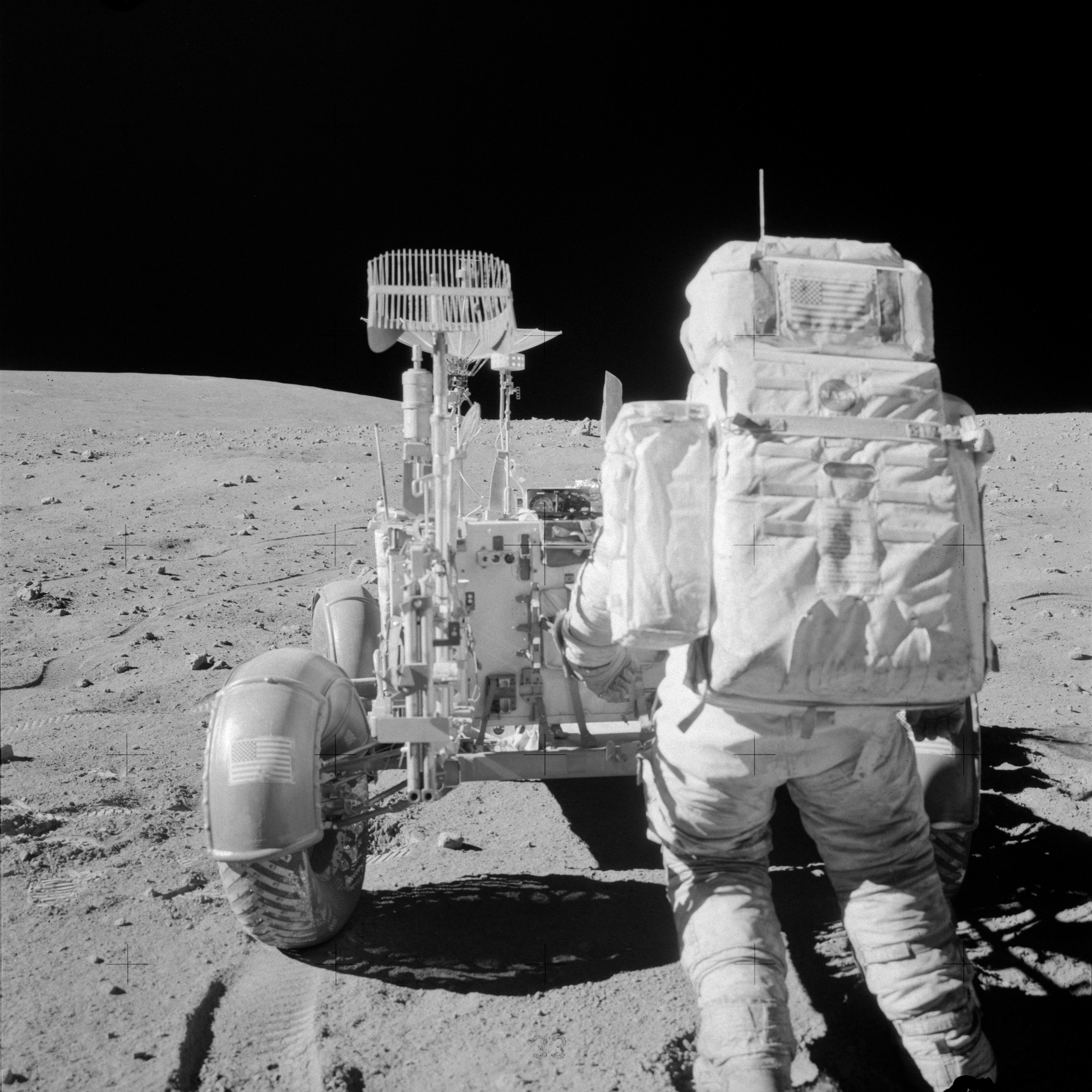
AS16-108-17622 (22 April 1972) --- Astronaut John W. Young, commander of the Apollo 16 lunar landing mission, reaches for tools in the Apollo Lunar Hand Tool Carrier at the aft end of the Lunar Roving Vehicle (LRV) during the second Apollo 16 extravehicular activity (EVA) at the Descartes landing site. This photograph was taken by astronaut Charles M. Duke Jr., lunar module pilot. This view is looking south from the base of Stone Mountain. While astronauts Young and Duke descended in the Lunar Module (LM) "Orion" to explore the Descartes highlands region of the moon, astronaut Thomas K. Mattingly II, command module pilot, remained with the Command and Service Modules (CSM) "Casper" in lunar orbit.

AS16-110-17960 (22 April 1972) --- Astronaut John W. Young, commander, replaces tools in the Apollo Lunar Hand Tool (ALHT) carrier at the aft end of the Lunar Roving Vehicle (LRV) during the second Apollo 16 extravehicular activity (EVA) on the high side of Stone Mountain at the Descartes landing site. Astronaut Charles M. Duke Jr., lunar module pilot, took this photograph near the conclusion of Station 4 activities. Smoky Mountain, with the large Ravine Crater on its flank, is in the left background. This view is looking northeast. While astronauts Young and Duke descended in the Apollo 16 Lunar Module (LM) "Orion" to explore the Descartes highlands landing site on the moon, astronaut Thomas K. Mattingly II, command module pilot, remained with the Command and Service Modules (CSM) "Casper" in lunar orbit.
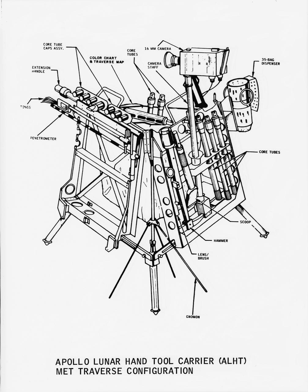
Line drawing of the Apollo Lunar Hand Tool Carrier (ALHT) MET Traverse Configuration for use during the Apollo 14 lunar landing mission
AS12-47-6932 (19 Nov. 1969) --- Close-up view of a set of tongs, an Apollo Lunar Hand Tool, being used by astronaut Charles Conrad Jr., commander, to pick up lunar samples during the Apollo 12 extravehicular activity. This photograph shows Conrad's legs and a good view of the lunar soil.
S70-20272 (December 1969) --- Astronaut James A. Lovell Jr., commander of the upcoming Apollo 13 lunar landing mission, uses a scoop from the Apollo Lunar Hand Tools (ALHT) during a simulated lunar surface traverse at the Kapoho, Hawaii training site. While at the Hawaii training sites, Lovell and Haise are participating in thorough rehearsals of their extravehicular activity (EVA). Photo credit: NASA
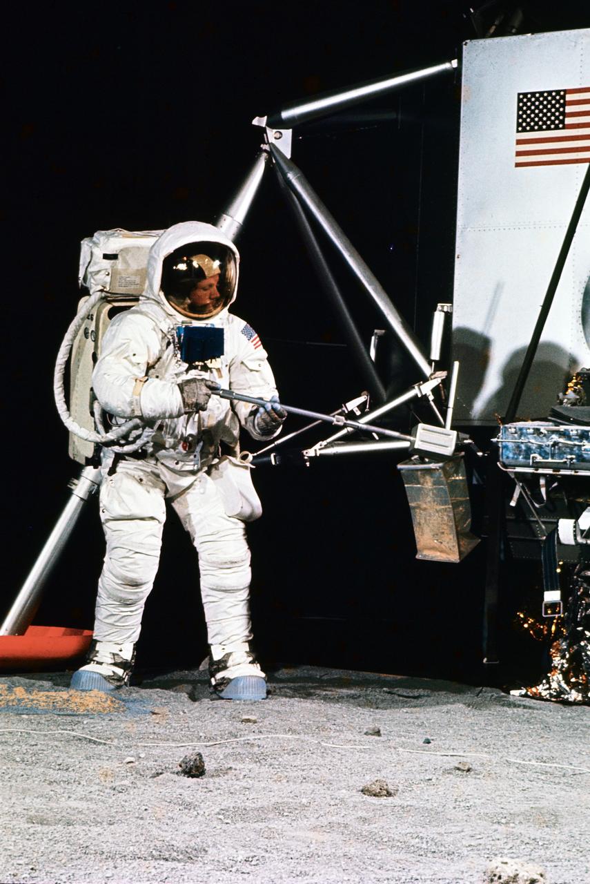
AS12-48-7149 (20 Nov. 1969) --- A close-up view of astronaut Charles Conrad Jr., commander of the Apollo 12 lunar landing mission, photographed during the extravehicular activity (EVA) on the surface of the moon. An EVA checklist is on Conrad's left wrist. A set of tongs, an Apollo Lunar Hand Tool (ALHT), is held in his right hand. Several footprints can be seen. Astronaut Richard F. Gordon Jr., command module pilot, remained with the Command and Service Modules (CSM) in lunar orbit while astronauts Conrad and Alan L. Bean, lunar module pilot, descended in the LM to explore the moon. Note lunar soil on the suit of Conrad, especially around the knees and below.

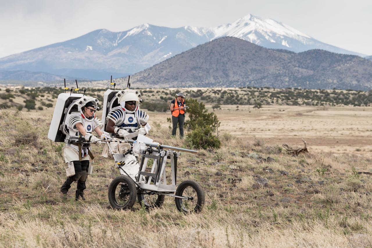
jsc2023e041422 --- Artemis II science trainers push a lunar tool cart across the lunar-like landscape of Iceland during an Artemis II crew geology field training.

S70-56433 (December 1970) --- Astronaut James B. Irwin, lunar module pilot of the Apollo 15 lunar landing mission, participates in lunar surface extravehicular activity (EVA) training during a visit to Hawaii. He is simulating using lunar surface geological tools to collect a core sample.
AS16-116-18671 (23 April 1972) --- Astronaut Charles M. Duke Jr., lunar module pilot, works at the "Shadow Rock", discovered during the missions third extravehicular activity (EVA) in the area of North Ray Crater (Station 13), April 23, 1972. The scoop, a geological hand tool, leans against the rock. This view was exposed by astronaut John W. Young, commander. The two moon-exploring crew men sampled this rock, which got its name because of a permanently shadowed area it protected. While astronauts Young and Duke descended in the Apollo 16 Lunar Module (LM) "Orion" to explore the Descartes highlands landing site on the moon, astronaut Thomas K. Mattingly II, command module pilot, remained with the Command and Service Modules (CSM) "Casper" in lunar orbit.
AS16-117-18728 (23 April 1972) --- Astronaut Charles M. Duke Jr., lunar module pilot, exposed this view of the huge "Shadow Rock" with his 70mm Hasselblad camera during the mission's third and final extravehicular activity (EVA), on April 23, 1972. This particular stop was referenced as Station 13. The scoop, a geological hand tool, leans against the rock and helps to give an idea of the size. Station 13 is a little southeast of North Ray Crater at the Descartes area. While astronauts John W. Young, commander; and Duke descended in the Apollo 16 Lunar Module (LM) "Orion" to explore the Descartes highlands landing site on the moon, astronaut Thomas K. Mattingly II, command module pilot, remained with the Command and Service Modules (CSM) "Casper" in lunar orbit.
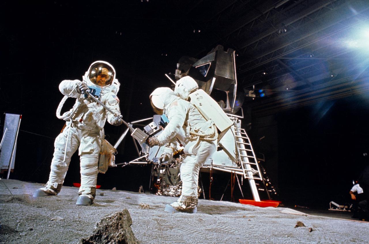
S71-16101 (January 1971) --- A Grumman Aerospace Corporation artist's concept of Apollo 14 crewmen, astronauts Alan B. Shepard Jr., commander, and Edgar D. Mitchell, lunar module pilot, as they set out on their first traverse. Shepard is pulling the Modularized Equipment Transporter (MET) which contains cameras, lunar sample bags, tools and other paraphernalia. Shepard has the Laser Ranging Retro-Reflector (LR-3) in his other hand. Mitchell is carrying the Apollo Lunar Surface Experiments Package (ALSEP) barbell mode.
Two members of the Apollo 11 lunar landing mission participate in a simulation of deploying and using lunar tools on the surface of the moon during a training exercise in bldg 9 on April 22, 1969. Astronaut Edwin E. Aldrin Jr. (on left), lunar module pilot, uses scoop and tongs to pick up sample. Astronaut Neil A. Armstrong, Apollo 11 commander, holds bag to receive sample. In the background is a Lunar Module mockup. Both men are wearing Extravehicular Mobility Units (EMU).
NASA astronaut Jessica Meir grabs a lunar geology tool from a tool rack on Lunar Outpost’s Eagle lunar terrain vehicle during testing at NASA’s Johnson Space Center. Image Credit: NASA/James Blair
S72-48890 (September 1972) --- Scientist-astronaut Harrison H. Schmitt, lunar module pilot of the Apollo 17 lunar landing mission, procures a geological hand tool from the tool carrier at the aft end of the Lunar Roving Vehicle during lunar surface extravehicular activity simulation training at the Kennedy Space Center (KSC), Florida. Schmitt grasps a scoop with extension handle in his right hand.
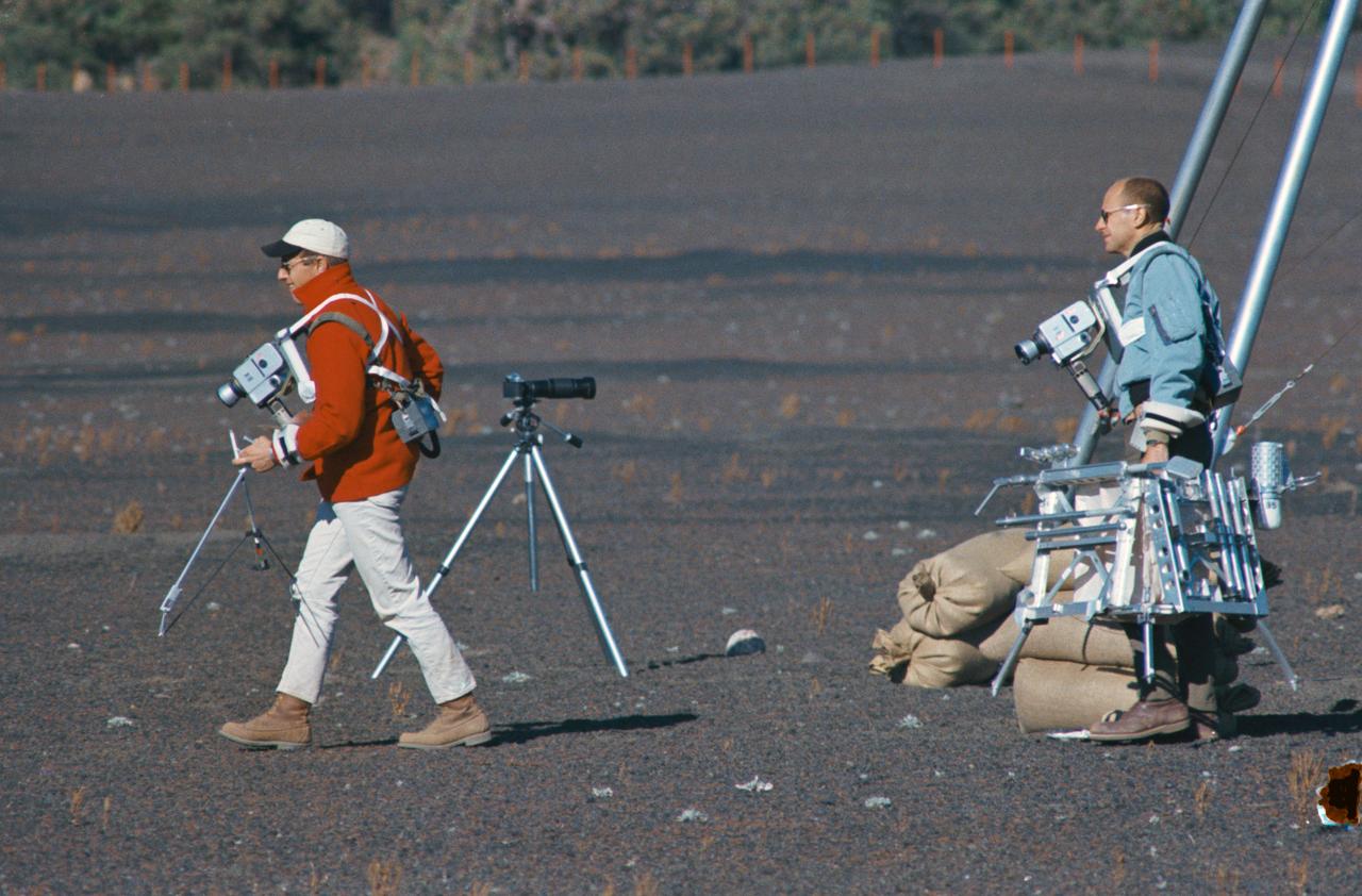
S69-55667 (10 Oct. 1969) --- Astronauts Charles Conrad Jr. and Alan L. Bean train for their upcoming Apollo 12 lunar landing mission. Here they are entering a simulated lunar surface area near Flagstaff, Arizona. Both are wearing lunar surface cameras strapped to their bodies. Conrad (left), the Apollo 12 mission commander, is carrying some of the tools from the geological tool container. The geological tool container, being carried here by Bean, the lunar module pilot, is similar to the one which will be used during scheduled extravehicular activity (EVA) periods on Nov. 19 and 20, 1969, on the lunar surface. While astronauts Conrad and Bean conduct their scheduled EVA on the moon's surface, astronaut Richard F. Gordon Jr., command module pilot, will man the Command and Service Modules (CSM) in lunar orbit.
S70-27037 (4 Feb. 1970) --- Astronaut James A. Lovell Jr., commander of the Apollo 13 lunar landing mission, simulates lunar surface extravehicular activity during training exercises in the Kennedy Space Center’s Flight Crew Training Building. Lovell, wearing an Extravehicular Mobility Unit (EMU), is holding an Apollo Lunar Hand Tool (a set of tongs) in his left hand. A gnomon is in front of his right foot. A tool carrier is in the right background.
AS17-147-22523 (11 Dec. 1972) --- Astronaut Eugene A. Cernan is seen test driving the "stripped down" Lunar Rover Vehicle (LRV) prior to loading the LRV up. Equipment later loaded onto the LRV included the ground controlled television assembly, the lunar communications relay unit, the hi-gain antenna, the low-gain antenna, aft tool pallet, and lunar tools and scientific gear.

NASA astronaut Jessica Watkins picks up a lunar geology tool from a stowage drawer on Astrolab’s FLEX lunar terrain vehicle during testing at NASA’s Johnson Space Center. Image Credit: NASA/Robert Markowitz
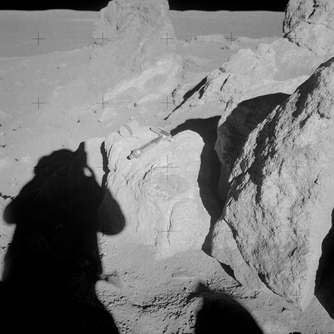
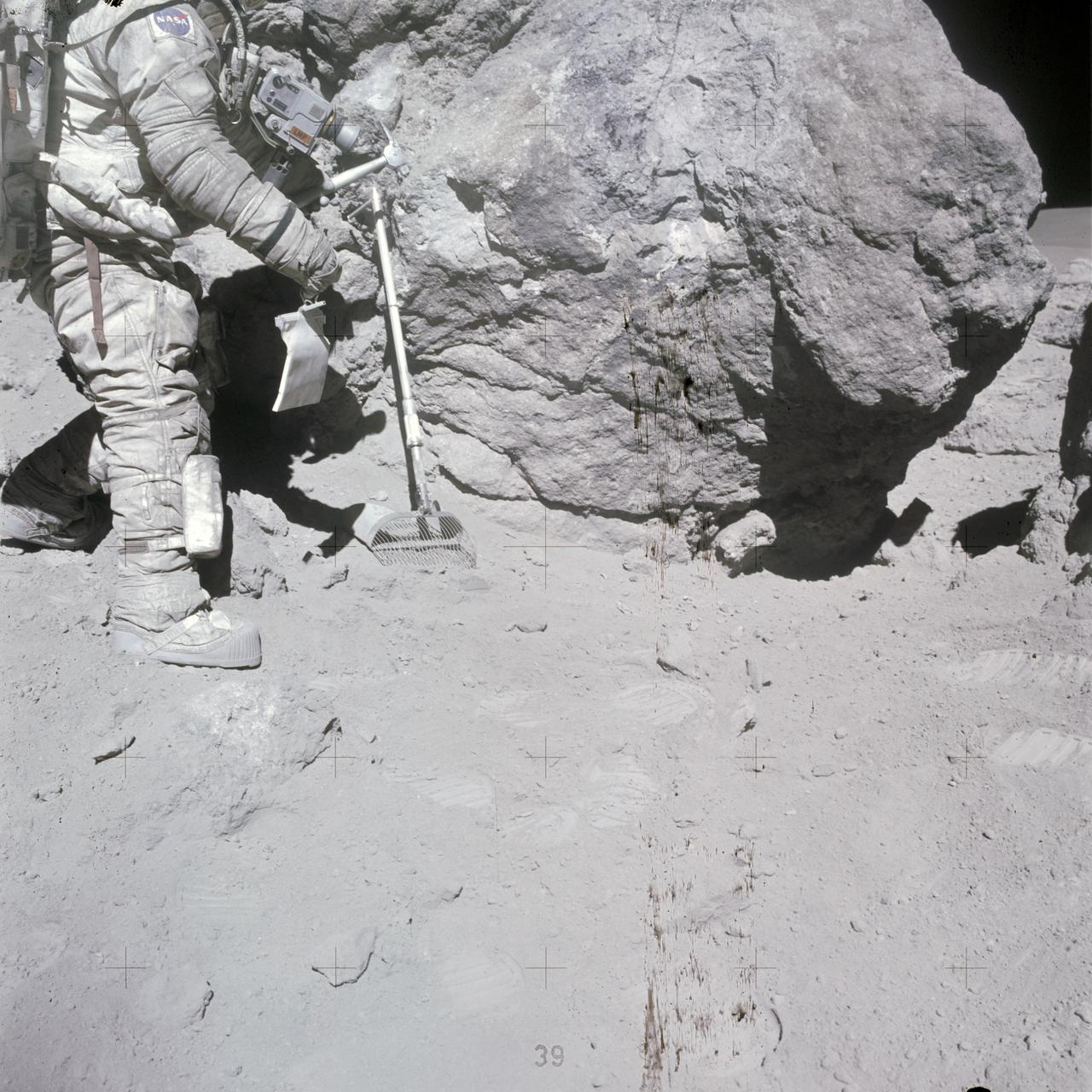
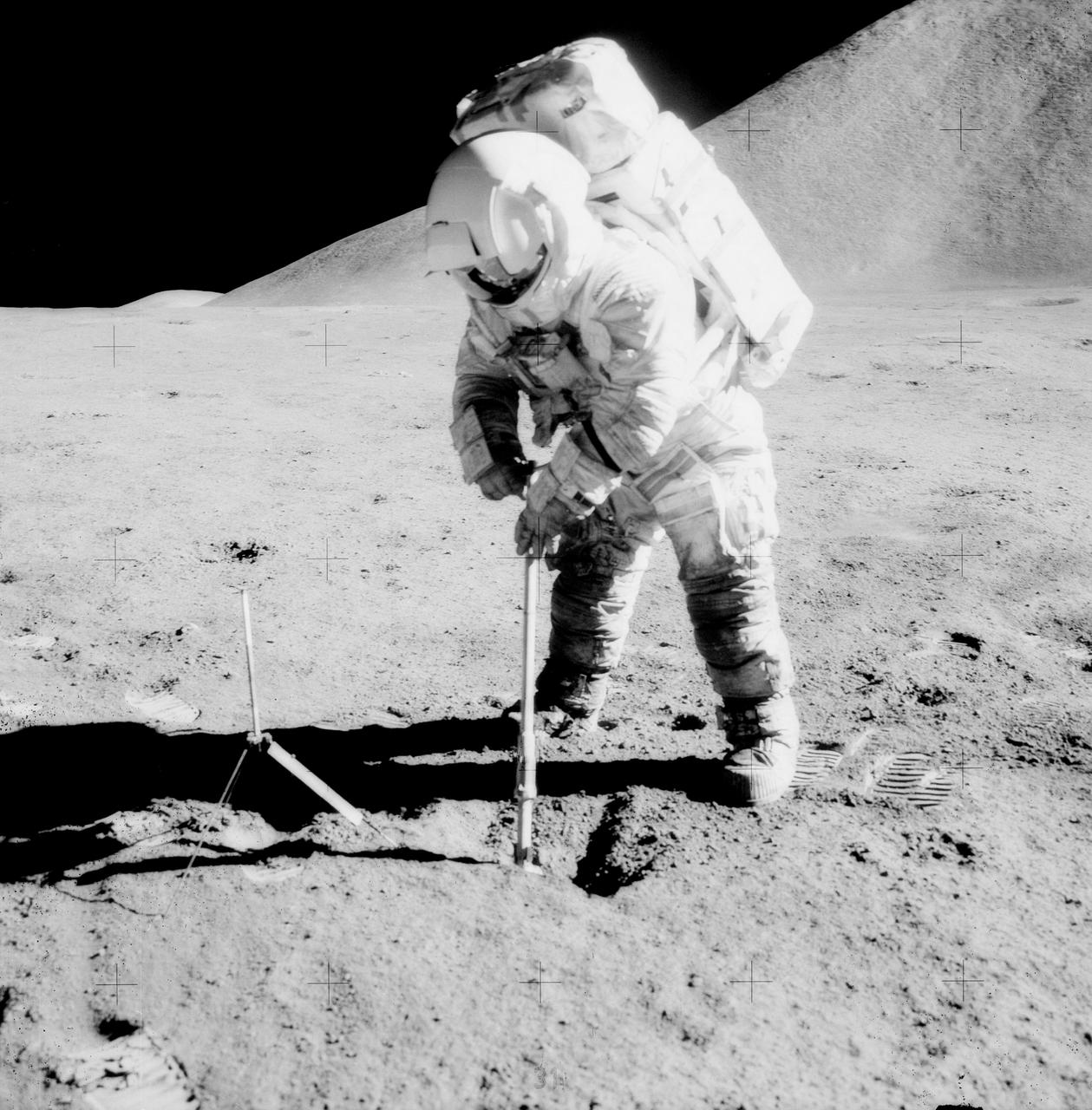
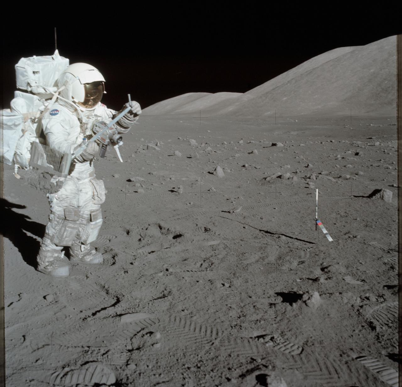
AS14-68-9453 (6 Feb. 1971) --- Astronaut Edgar D. Mitchell, lunar module pilot, whose shadow is in the foreground, photographs a group of large boulders near the rim of Cone Crater. An interesting feature is the white and brown rock in the boulder. Mitchell removed a sample where the hammer is lying. While astronauts Alan B. Shepard Jr., commander, and Mitchell descended in the Lunar Module (LM) "Antares" to explore the Fra Mauro region of the moon, astronaut Stuart A. Roosa, command module pilot, remained with the Command and Service Modules (CSM) "Kitty Hawk" in lunar orbit.
AS16-116-18653 (23 April 1972) --- Astronaut Charles M. Duke Jr., Apollo 16 lunar module pilot, stands at a big rock adjacent (south) to the huge "House Rock" (barely out of view at right edge). Note shadow at extreme right center where the two moon-exploring crew members of the mission sampled what they referred to as the "east-by-west split of House Rock" or the open space between this rock and "House Rock". At their post-mission press conference, the crewmen expressed the opinion that this rock was once a part of "House Rock" which had broken away. The two sampled the big boulder seen here also. Duke has a sample bag in his hand, and a lunar surface rake leans against the large boulder. Astronaut John W. Young, commander, exposed this view with a color magazine in his 70mm Hasselblad camera. While astronauts Young and Duke descended in the Apollo 16 Lunar Module (LM) "Orion" to explore the Descartes highlands landing site on the moon, astronaut Thomas K. Mattingly II, command module pilot, remained with the Command and Service Modules (CSM) "Casper" in lunar orbit.
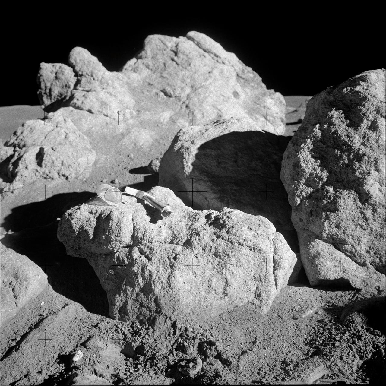
AS14-68-9452 (5-6 Feb. 1971) --- A hammer and a small collection bag lie atop a lunar boulder to give some indication of size in this view of several boulders clustered together. This is one of the white rocks from which samples were taken by the two moon-exploring crew men of the Apollo 14 lunar landing mission. While astronauts Alan B. Shepard Jr., commander, and Edgar D. Mitchell, lunar module pilot, were exploring the moon, astronaut Stuart A. Roosa, command module pilot, remained with the Command and Service Modules (CSM) in lunar orbit.
S69-32240 (22 April 1969) --- Astronaut Neil A. Armstrong, wearing an Extravehicular Mobility Unit, participates in a simulation of deploying and using lunar tools on the surface of the moon during a training exercise in Building 9 on April 22, 1969. Armstrong is the commander of the Apollo 11 lunar landing mission. In the background is a Lunar Module mock-up.
S70-28229 (16 Jan. 1970) --- Astronaut James A. Lovell Jr., commander of the Apollo 13 lunar landing mission, participates in lunar surface simulation training at the Manned Spacecraft Center. Lovell is attached to a Six Degrees of Freedom Simulator. He is carrying an Apollo Lunar Hand Tools carrier in his right hand.
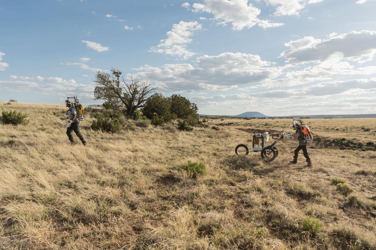
NASA astronauts Kate Rubins and Andre Douglas push a tool cart loaded with lunar tools through the San Francisco Volcanic Field north of Flagstaff, Arizona, as they practice moonwalking operations for Artemis III on May 13, 2024. Credit: NASA/Josh Valcarcel
AS17-147-22526 (11 Dec. 1972) --- Astronaut Eugene A. Cernan, commander, makes a short checkout of the Lunar Roving Vehicle (LRV) during the early part of the first Apollo 17 extravehicular activity (EVA) at the Taurus-Littrow landing site. This view of the "stripped down" LRV is prior to loading up. Equipment later loaded onto the LRV included the ground-controlled television assembly, the lunar communications relay unit, hi-gain antenna, low-gain antenna, aft tool pallet, lunar tools and scientific gear. This photograph was taken by scientist-astronaut Harrison H. Schmitt, lunar module pilot. The mountain in the right background is the east end of South Massif. While astronauts Cernan and Schmitt descended in the Lunar Module (LM) "Challenger" to explore the moon, astronaut Ronald E. Evans, command module pilot, remained with the Command and Service Modules (CSM) "America" in lunar orbit.
S70-34415 (April 1970) --- Astronaut Alan B. Shepard Jr., prime crew commander of the Apollo 14 mission, uses a trenching tool during a simulation of a traverse on the lunar surface. Members of the Apollo 14 prime and backup crews were in Hawaii to train for the extravehicular activity of their upcoming mission. Features of the terrain at Kapoho and other Hawaiian sites are very similar to those found on the lunar surface. A modular equipment transporter (MET), nicknamed the "Rickshaw" because of its appearance and method of propulsion, is behind Shepard, and a gnomon, one of the Apollo lunar hand tools (ALHT) is at extreme left.
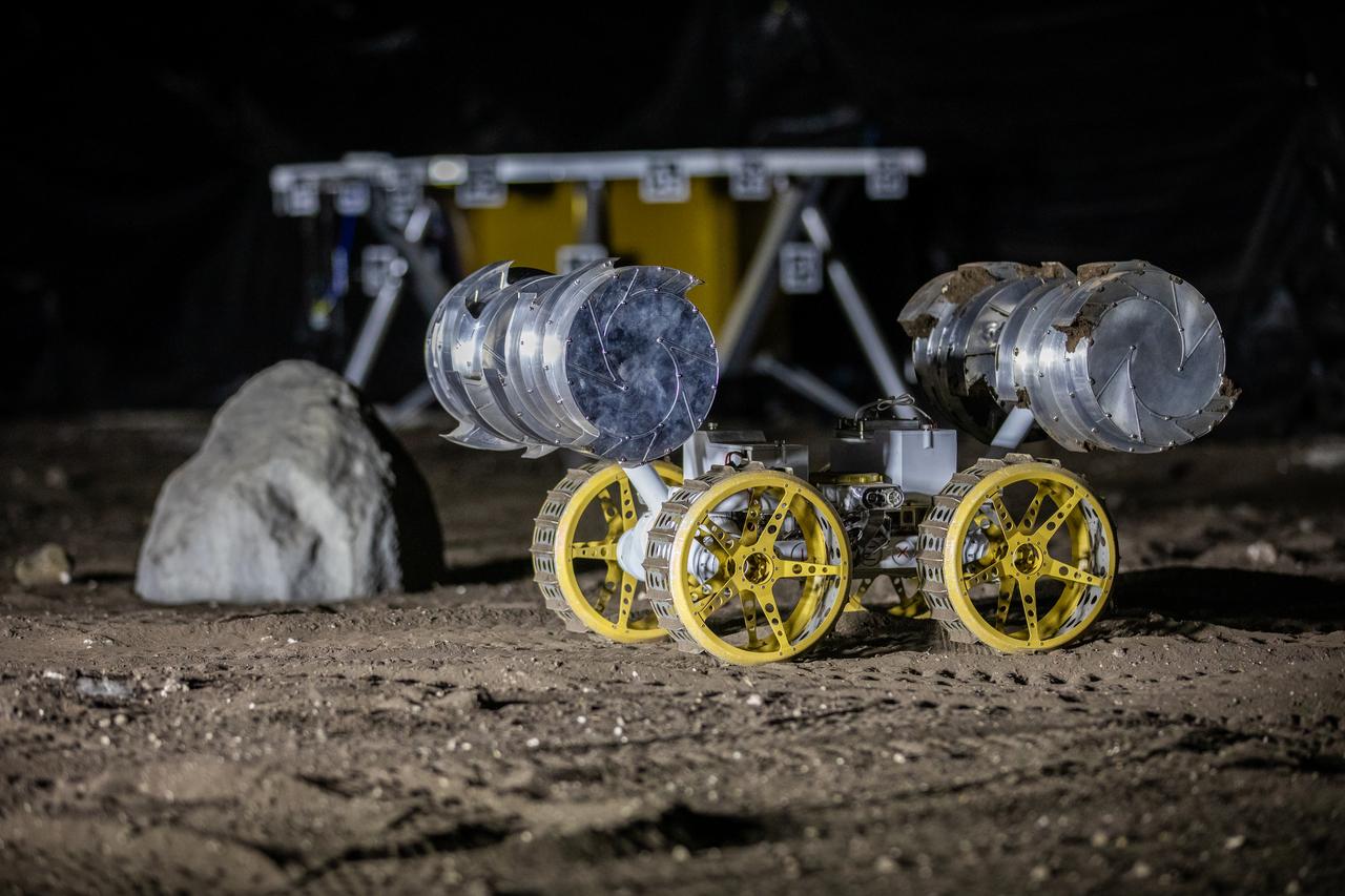
NASA’s ISRU Pilot Excavator (IPEx) performs a simulated lunar mission in a testbed at the agency’s Kennedy Space Center on Friday, Aug. 30, 2024. IPEx functions as both an excavator and a dump truck to mine and transport lunar regolith, the loose rocky material on the Moon’s surface, which is crucial for future lunar missions and In-Situ Resource Utilization (ISRU) processes. This dual capability makes IPEx an indispensable tool for sustainable lunar exploration.
NASA’s ISRU Pilot Excavator (IPEx) performs a simulated lunar mission in a testbed at the agency’s Kennedy Space Center on Friday, Aug. 30, 2024. IPEx functions as both an excavator and a dump truck to mine and transport lunar regolith, the loose rocky material on the Moon’s surface, which is crucial for future lunar missions and In-Situ Resource Utilization (ISRU) processes. This dual capability makes IPEx an indispensable tool for sustainable lunar exploration.
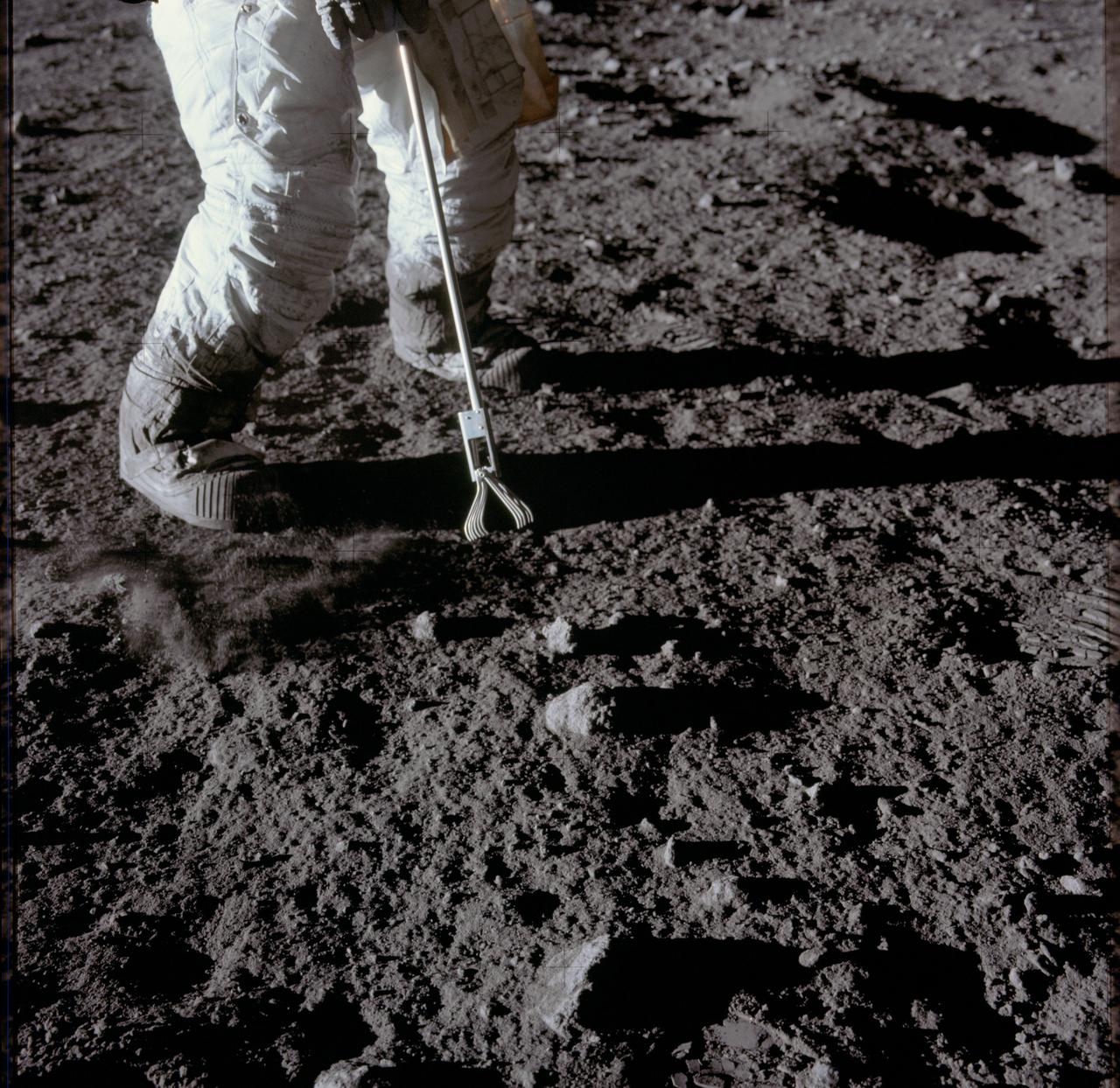
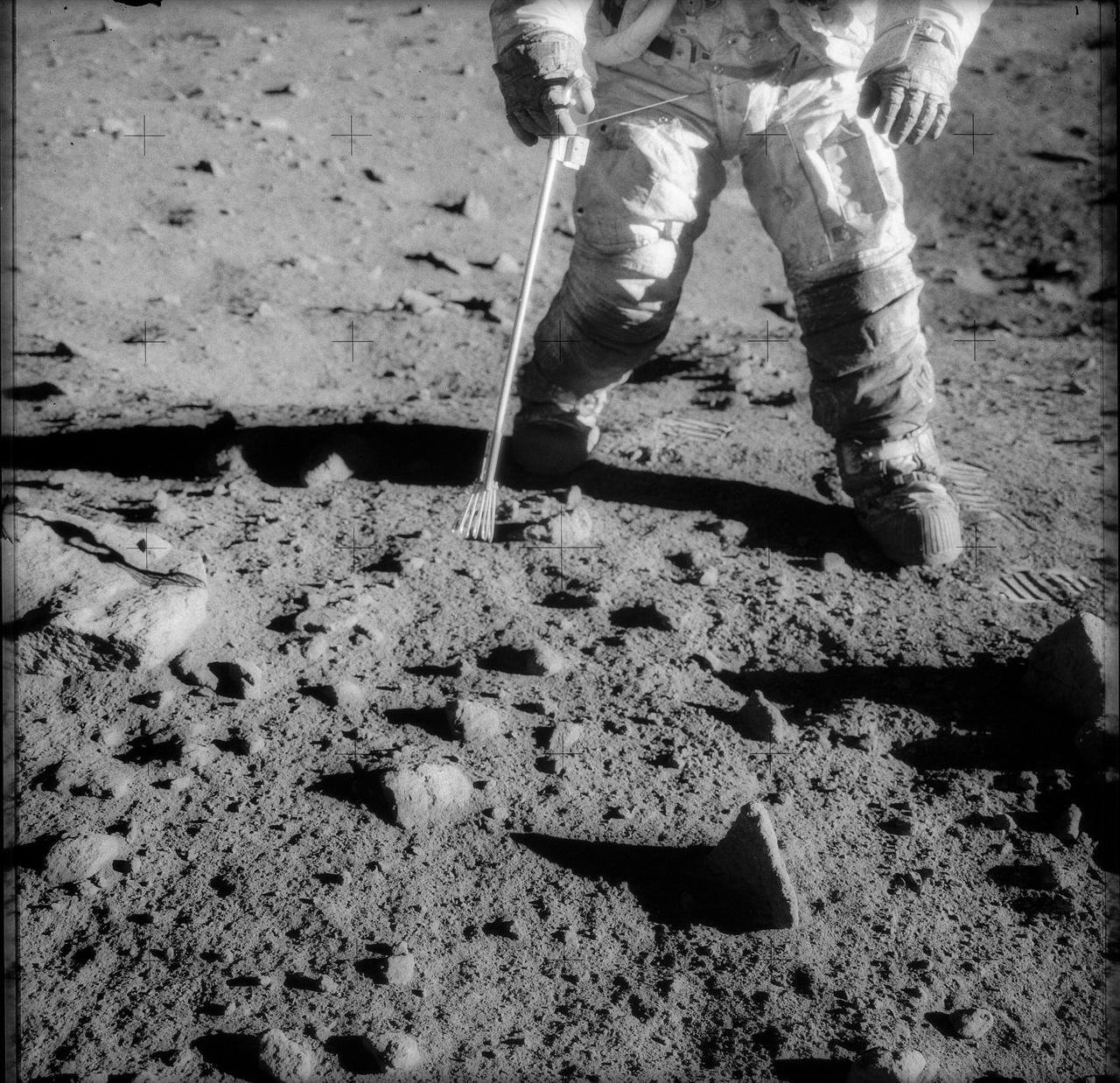
AS17-134-20425 (11 Dec. 1972) --- Scientist-astronaut Harrison H. Schmitt, lunar module pilot, collects lunar rake samples at Station 1 during the first Apollo 17 extravehicular activity (EVA) at the Taurus-Littrow landing site. This picture was taken by astronaut Eugene Cernan, commander. The lunar rake, an Apollo lunar geology hand tool, is used to collect discrete samples of rocks and rock chips ranging in size from one-half inch (1.3 centimeter) to one inch (2.5 centimeter).
S69-32233 (22 April 1969) --- Two members of the Apollo 11 lunar landing mission participate in a simulation of deploying and using lunar tools on the surface of the moon. The rehearsal took place during a training exercise in building 9 on April 22, 1969. Astronaut Edwin E. Aldrin Jr. (on left), lunar module pilot, uses a scoop and tongs to pick up samples. Astronaut Neil A. Armstrong, Apollo 11 commander, holds the bag to receive the sample. In the background is a Lunar Module (LM) mock-up.
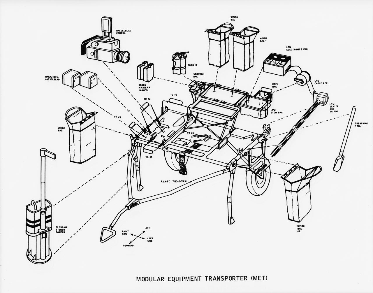
S70-50762 (November 1970) --- A line drawing illustrating layout view of the modular equipment transporter (MET) and its equipment. A MET (or Rickshaw, as it has been nicknamed) will be used on the lunar surface for the first time during the Apollo 14 lunar landing mission. The Rickshaw will serve as a portable workbench with a place for the Apollo lunar hand tools (ALHT) and their carrier, three cameras, two sample container bags, a special environment sample container (SESC), a lunar portable magnetometer (LPM) and spare film magazines.
AS12-47-6988 (19 Nov. 1969) --- Astronaut Charles Conrad Jr., commander of the Apollo 12 lunar landing mission, stands at the Module Equipment Stowage Assembly (MESA) on the Lunar Module (LM) following the first Apollo 12 extravehicular activity (EVA) on the lunar surface. The erectable S-band antenna is already deployed at right. The carrier for the Apollo Lunar Hand Tools (ALHT) is near Conrad. While astronauts Conrad and Alan L. Bean, lunar module pilot, descended in the LM to explore the lunar surface, astronaut Richard F. Gordon Jr., command module pilot, remained with the Command and Service Modules (CSM) in lunar orbit.
AS15-92-12424 (31 July-2 Aug. 1971) --- Astronaut James B. Irwin, lunar module pilot, uses a scoop in making a trench in the lunar soil during Apollo 15 extravehicular activity (EVA) on the moon. Mount Hadley, which rises approximately 14,765 feet (about 4,500 meters) above the plain, is in the background. Its base is some 14 kilometers (about 8.4 miles) away. The gnomon is at left. While astronauts Irwin, and David R. Scott, commander, descended in the Lunar Module (LM) to explore the moon, astronaut Alfred M. Worden, command module pilot, remained with the Command and Service Modules (CSM) in lunar orbit.
A team from the Granular Mechanics and Regolith Operations lab who developed and tested NASA’s ISRU Pilot Excavator (IPEx) pose for a photo on Friday, Aug. 30, 2024, in a testbed located at NASA’s Kennedy Space Center in Florida. IPEx functions as both an excavator and a dump truck to mine and transport lunar regolith, the loose rocky material on the Moon’s surface, which is crucial for future lunar missions and In-Situ Resource Utilization (ISRU) processes. This dual capability makes IPEx an indispensable tool for sustainable lunar exploration.
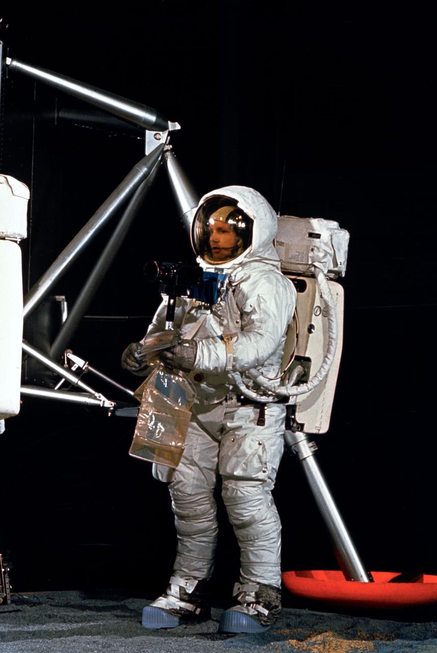
S69-32242 (22 April 1969) --- Astronaut Neil A. Armstrong, wearing an Extravehicular Mobility Unit (EMU), participates in a simulation of deploying and using lunar tools, on the surface of the moon, during a training exercise in Building 9 on April 22, 1969. Armstrong, commander of the Apollo 11 lunar landing mission, is holding sample bags. On the left is the Lunar Module (LM) mock-up.
S69-32248 (22 April 1969) --- Astronaut Neil A. Armstrong, wearing an Extravehicular Mobility Unit (EMU), participates in a simulation of deploying and using lunar tools, on the surface of the moon, during a training exercise in Building 9 on April 22, 1969. Armstrong is the commander of the Apollo 11 lunar landing mission. He is using a scoop to place the sample into bag. On the right is a Lunar Module (LM) mock-up.
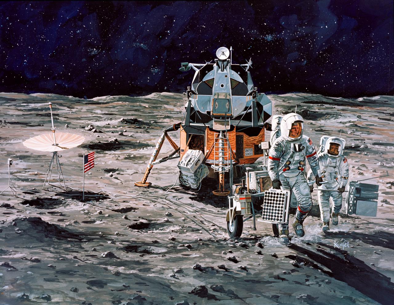
S71-16102 (January 1971) --- A Grumman Aerospace Corporation artist's concept of Apollo 14 crewmen, astronauts Alan B. Shepard Jr., commander, and Edgar D. Mitchell, lunar module pilot, as they set out on their first traverse. Shepard is pulling the Modularized Equipment Transporter (MET) which contains cameras, lunar sample bags, tools and other paraphernalia. Shepard has the Laser Ranging Retro-Reflector (LR3) in his other hand. Mitchell is carrying the Apollo Lunar Surface Experiments Package (ALSEP) barbell mode.
AS17-146-22296 (13 Dec. 1972) --- Astronaut Harrison H. Schmitt, lunar module pilot, works near the Lunar Roving Vehicle (LRV) during the third Apollo 17 extravehicular activity (EVA) at the Taurus-Littrow site on the lunar surface. The front part of the LRV is out of frame at left, but the seats and several geological tools can be seen. The photo was taken by astronaut Eugene A. Cernan, mission commander.
Apollo-era technology spurred the development of cordless products that we take for granted everyday. In the 1960s, NASA asked Black Decker to develop a special drill that would be powerful enough to cut through hard layers of the lunar surface and be lightweight, compact, and operate under its own power source, allowing Apollo astronauts to collect lunar samples further away from the Lunar Experiment Module. In response, Black Decker developed a computer program that analyzed and optimized drill motor operations. From their analysis, engineers were able to design a motor that was powerful yet required minimal battery power to operate. Since those first days of cordless products, Black Decker has continued to refine this technology and they now sell their rechargeable products worldwide (i.e. the Dustbuster, cordless tools for home and industrial use, and medical tools.)
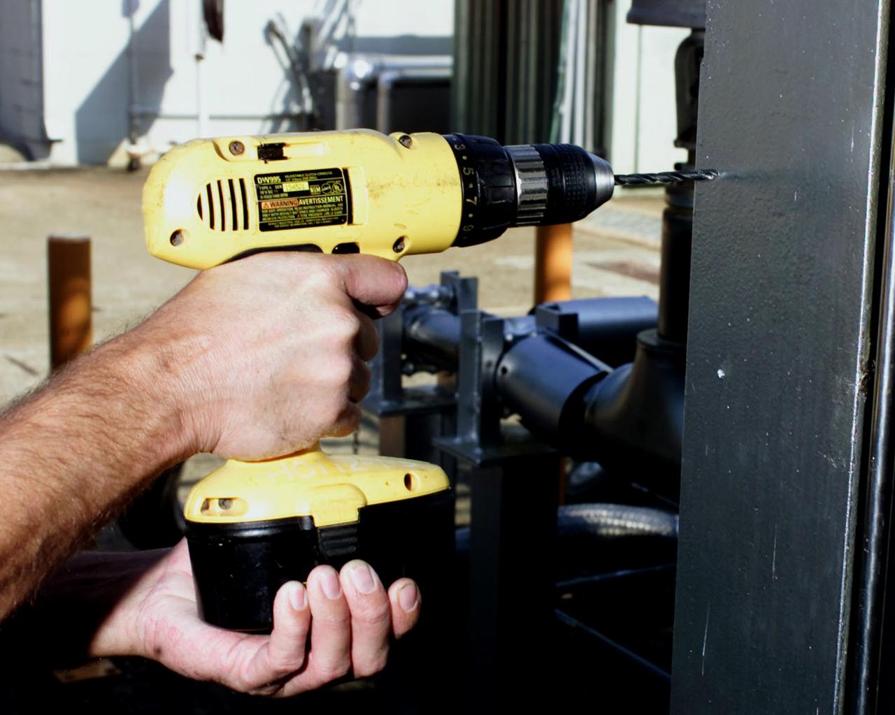
Apollo-era technology spurred the development of cordless products that we take for granted everyday. In the 1960s, NASA asked Black Decker to develop a special drill that would be powerful enough to cut through hard layers of the lunar surface and be lightweight, compact, and operate under its own power source, allowing Apollo astronauts to collect lunar samples further away from the Lunar Experiment Module. In response, Black Decker developed a computer program that analyzed and optimized drill motor operations. From their analysis, engineers were able to design a motor that was powerful yet required minimal battery power to operate. Since those first days of cordless products, Black Decker has continued to refine this technology and they now sell their rechargeable products worldwide (i.e. the Dustbuster, cordless tools for home and industrial use, and medical tools.)
S69-32243 (22 April 1969) --- Two members of the Apollo 11 lunar landing mission participate in a simulation of deploying and using lunar tools, on the surface of the moon, during a training exercise in Building 9 on April 22, 1969. Astronaut Edwin E. Aldrin Jr. (on left), lunar module pilot, uses a scoop to pick up a sample. Astronaut Neil A. Armstrong, Apollo 11 commander, holds bag to receive sample. In the background is a Lunar Module (LM) mock-up. Both crewmembers are wearing Extravehicular Mobility Units (EMU).
AS17-134-20426 (11 Dec. 1972) --- Scientist-astronaut Harrison H. Schmitt collects lunar rake samples at Station 1 during the first Apollo 17 extravehicular activity (EVA) at the Taurus-Littrow landing site. This picture was taken by astronaut Eugene A. Cernan, Apollo 17 commander. Schmitt is the lunar module pilot. The Lunar Rake, an Apollo Lunar Geology Hand Tool, is used to collect discrete samples of rocks and rock chips ranging in size from one-half inch (1.3 cm) to one inch (2.5 cm).
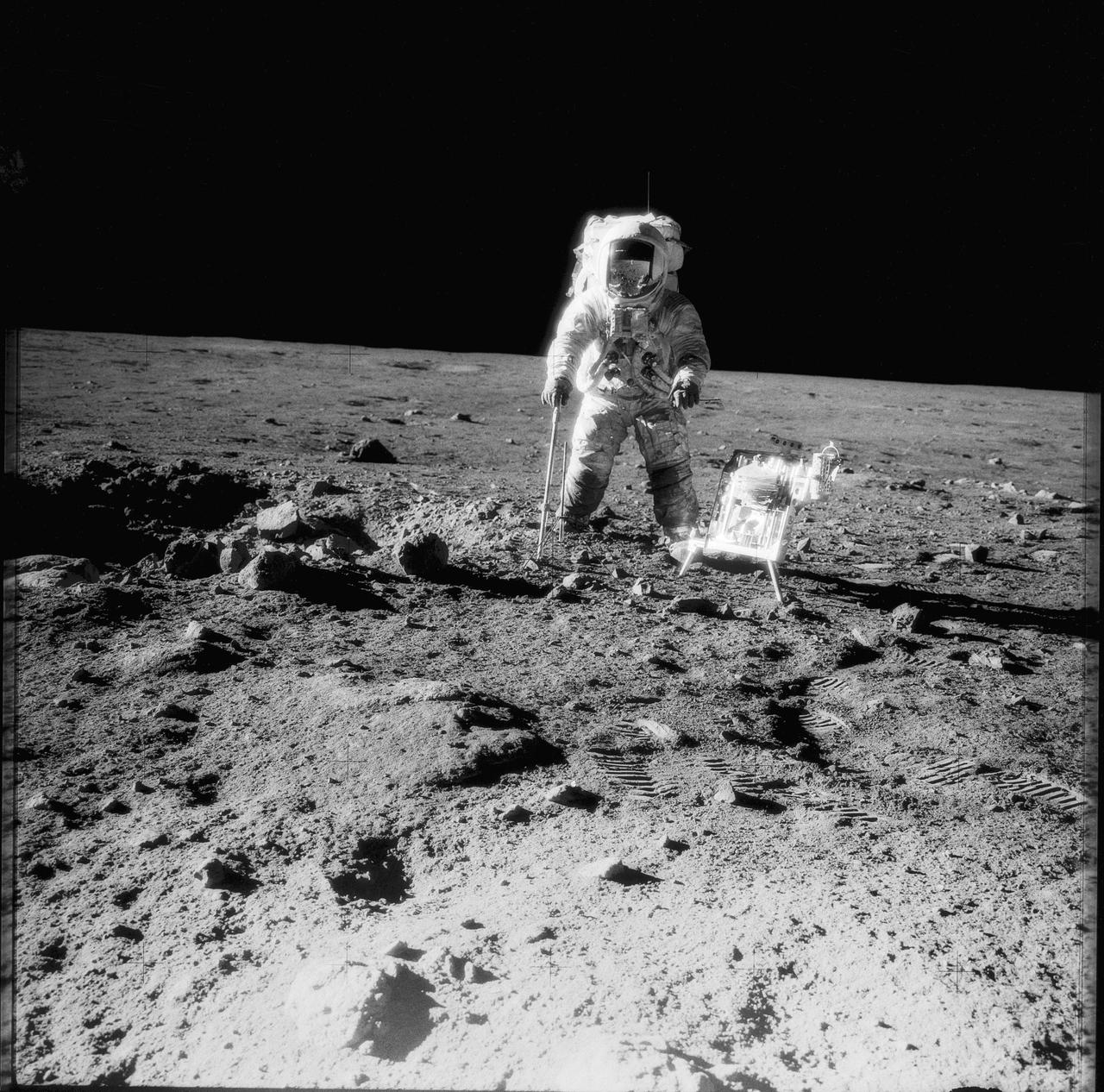
AS12-49-7281 (19-20 Nov 1969) --- Astronaut Alan L. Bean, lunar module pilot, pauses near a tool carrier during extravehicular activity (EVA) on the Moon's surface. Astronaut Charles Conrad, Jr., commander, who took the black and white photo, is reflected in Bean's helmet visor. Conrad and Bean had descended in the Apollo 12 Lunar Module (LM) "Intrepid" to explore the lunar surface while Astronaut Richard F. Gordon, Jr., command module pilot, remained with the Command and Service Modules (CSM) "Yankee Clipper" in lunar orbit. Photo credit: NASA
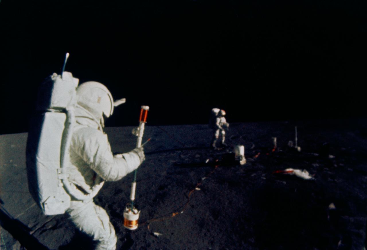
S71-19509 (5 Feb. 1971) --- Astronaut Edgar D. Mitchell, lunar module pilot, operates the Active Seismic Experiment's (ASE) thumper during the first Apollo 14 extravehicular activity (EVA) on the moon. Astronaut Alan B. Shepard Jr., commander, walks near deployed components of the Apollo Lunar Surface Experiments Package (ALSEP) in the background. This photograph was taken by an automatic 16mm camera mounted on the Apollo lunar hand tool carrier aboard the Modularized Equipment Transporter (MET). While astronauts Shepard and Mitchell descended in the LM to explore the moon, astronaut Stuart A. Roosa, command module pilot, remained with the Command and Service Modules (CSM) in lunar orbit.
S70-46191 (July 1970) --- Astronaut Alan B. Shepard Jr., commander of the Apollo 14 lunar landing mission, participates in lunar surface training at the Kennedy Space Center (KSC). Shepard is adjusting a camera mounted to the modular equipment transporter (MET). The MET, nicknamed the "Rickshaw", will serve as a portable work bench with a place for the Apollo lunar hand tools and their carrier, three cameras, two sample container bags, a special environment sample container, spare magazines, and a lunar surface Penetrometer. Shepard is wearing an Extravehicular Mobility Unit (EMU).
S70-46157 (July 1970) --- Astronaut Alan B. Shepard Jr., commander of the Apollo 14 lunar landing mission, participates in lunar surface simulation training at the Kennedy Space Center (KSC). The modular equipment transporter (MET) is in the left background, in the center foreground is a gnomon. The MET, nicknamed the "Rickshaw", will serve as a portable work bench with a place for the Apollo lunar hand tools and their carrier, three cameras, two sample container bags, a special environment sample container, spare magazines, and a lunar surface Penetrometer. Shepard is wearing an Extravehicular Mobility Unit (EMU).
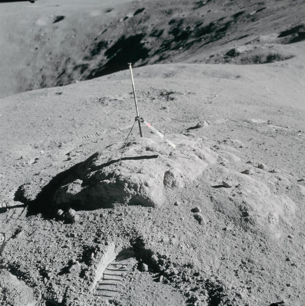
AS16-114-18412 (16-27 April 1972) --- The gnomon and color patch, one of the Apollo Lunar Hand Tools (ALHT), is deployed atop a lunar rock, in this photograph taken by one of the Apollo 16 astronauts during their lunar surface extravehicular activity (EVA) at the Descartes landing site. The gnomon is used as a photographic reference to establish local vertical sun angle, scale, and lunar color. The color patch, mounted on one of the legs of the tripod, provides a larger target for accurately determining colors in color photography. A portion of Flag Crater can be seen in the background. While astronauts John W. Young, commander; and Charles M. Duke Jr., lunar module pilot; descended in the Apollo 16 Lunar Module (LM) "Orion" to explore the Descartes highlands landing site on the moon, astronaut Thomas K. Mattingly II, command module pilot, remained with the Command and Service Modules (CSM) "Casper" in lunar orbit.
An Axiom Space engineer kneels down to collect simulated lunar samples using a geology tool while wearing the AxEMU (Axiom Extravehicular Mobility Unit) spacesuit during testing at NASA’s Johnson Space Center. Image Credit: Axiom Space
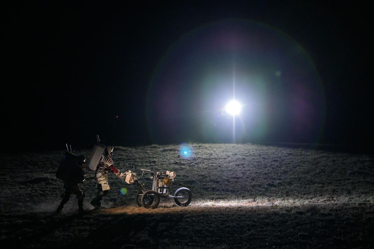
NASA astronaut Andre Douglas pushes a tool cart across the lunar-like landscape while NASA astronaut Kate Rubins follows close behind during a¬¬ nighttime simulated moonwalk in the San Francisco Volcanic Field in Northern Arizona on May 16, 2024. Credit: NASA/Josh Valcarcel
NASA astronaut Andre Douglas leads the way while NASA astronaut Kate Rubins follows behind with a lunar tool cart during a simulated moonwalk in the San Francisco Volcanic Field in Northern Arizona on May 17, 2024. Credit: NASA/Josh Valcarcel
A NASA crew member practices using lunar tools to collect geology samples at NASA’s Johnson Space Center during an elevated suit pressure test where teams evaluate how well crew perform tasks in different suit pressure levels while wearing the Artemis III lunar spacesuit developed by Axiom Space called the AxEMU (Axiom Extravehicular Mobility Unit).
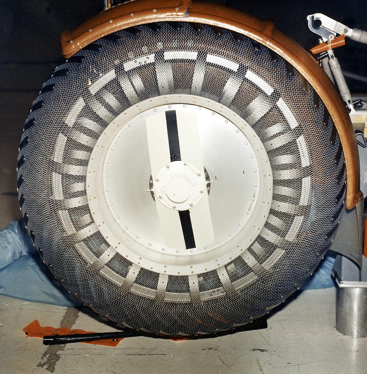
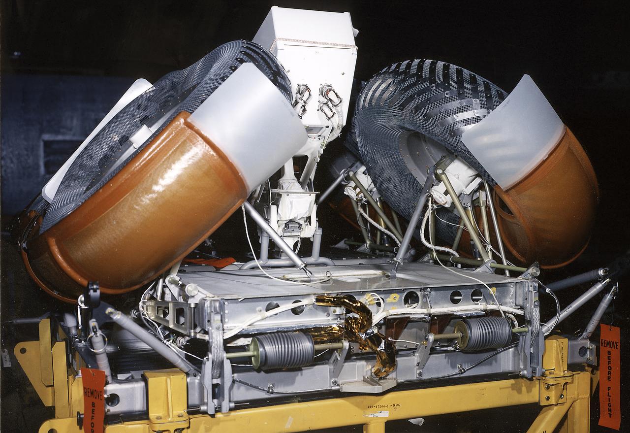
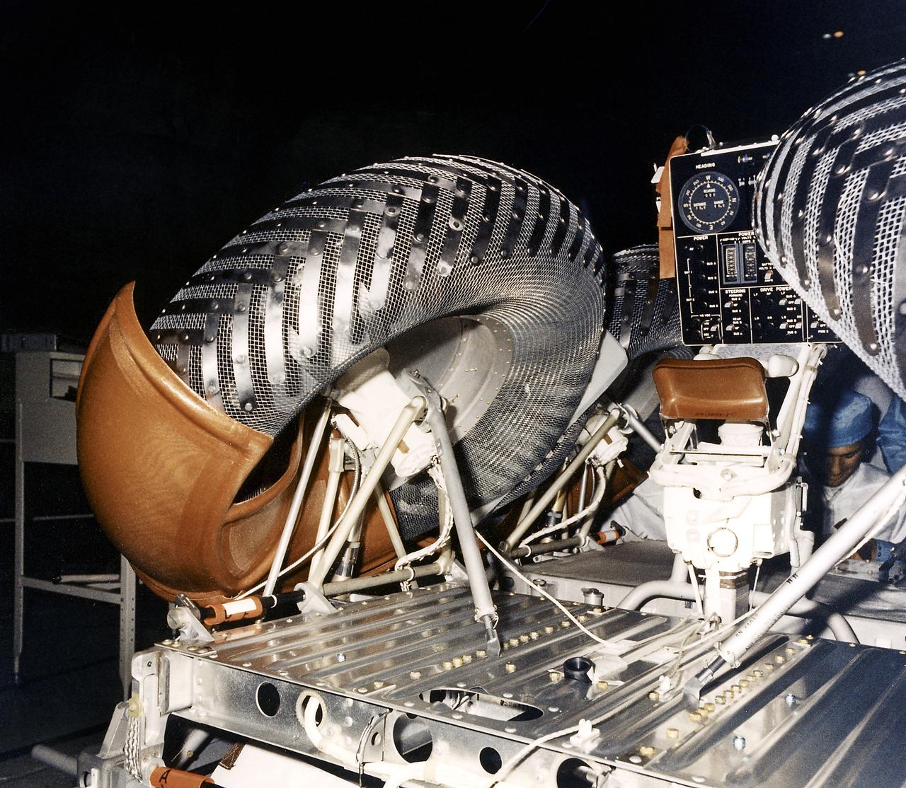
This is a close-up view of a left front wheel of the Lunar Roving Vehicle (LRV) No. 1. The LRV was built to give Apollo astronauts a greater range of mobility during lunar exploration. It was an open-space and collapsible vehicle about 10 feet long with large mesh wheels, anterna, appendages, tool caddies, and camera. An LRV was used on each of the last three Apollo missions; Apollo 15, Apollo 16, and Apollo 17. It was built by the Boeing Company under the direction of the Marshall Space Flight Center.
This is a close-up inboard view of a left front wheel of the Lunar Roving Vehicle (LRV) No. 1. The LRV was built to give Apollo astronauts a greater Range of mobility during lunar exploration. It was an open-space and collapsible vehicle about 10 feet long with large mesh wheels, anterna, appendages, tool caddies, and camera. An LRV was used on each of the last three Apollo missions; Apollo 15, Apollo 16, and Apollo 17. It was built by the Boeing Company under the direction of the Marshall Space Flight Center.
A NASA crew member practices using lunar tools to collect geology samples at NASA’s Johnson Space Center during an elevated suit pressure test where teams evaluate how well crew perform tasks in different suit pressure levels while wearing the Artemis III lunar spacesuit developed by Axiom Space called the AxEMU (Axiom Extravehicular Mobility Unit).
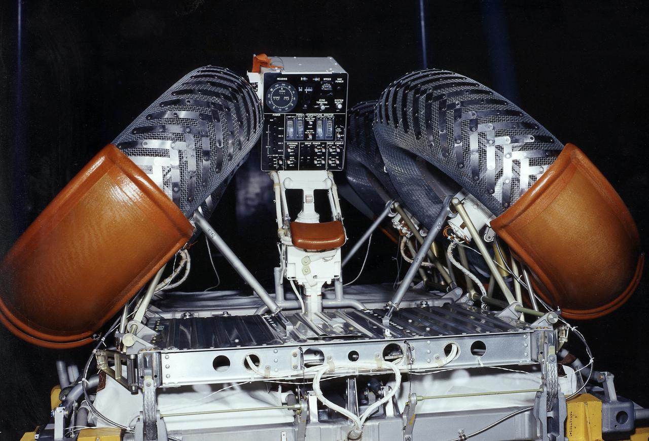
This photograph shows a rear view of a folded configuration of the Lunar Roving Vehicle (LRV) No. 2. The LRV was built to give Apollo astronauts a greater range of mobility during lunar exploration. It was an open-space and collapsible vehicle about 10 feet long with large mesh wheels, anterna, appendages, tool caddies, and camera. An LRV was used on each of the last three Apollo missions; Apollo 15, Apollo 16, and Apollo 17. It was built by the Boeing Company under the direction of the Marshall Space Flight Center.
This photograph shows a front view of a folded configuration of the Lunar Roving Vehicle (LRV) No. 2. The LRV was built to give Apollo astronauts a greater range of mobility during lunar exploration. It was an open-space and collapsible vehicle about 10 feet long with large mesh wheels, anterna, appendages, tool caddies, and camera. An LRV was used on each of the last three Apollo missions; Apollo 15, Apollo 16, and Apollo 17. It was built by the Boeing Company under the direction of the Marshall Space Flight Center.
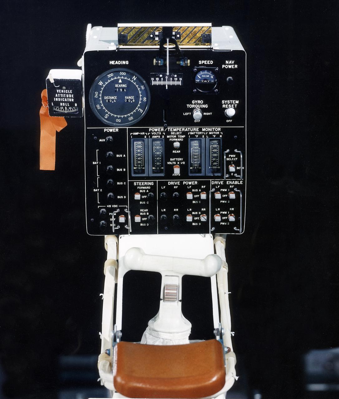
This photograph is a view of a display, control console, and hand controller for the Lunar Roving Vehicle (LRV) No. 2. The LRV was built to give Apollo astronauts a greater range of mobility during lunar exploration. It was an open-space and collapsible vehicle about 10 feet long with large mesh wheels, anterna, appendages, tool caddies, and camera. An LRV was used on each of the last three Apollo missions; Apollo 15, Apollo 16, and Apollo 17. It was built by the Boeing Company under the direction of the Marshall Space Flight Center.
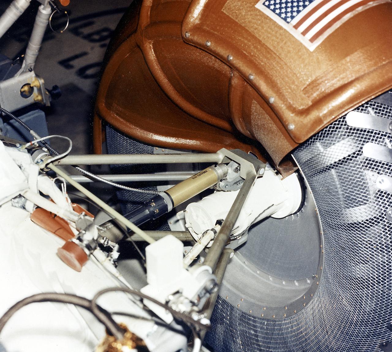
This is a close-up view of a right rear wheel strut of the Lunar Roving Vehicle (LRV) No. 1. The LRV was built to give Apollo astronauts a greater range of mobility during lunar exploration. It was an open-space and collapsible vehicle about 10 feet long with large mesh wheels, anterna, appendages, tool caddies, and camera. An LRV was used on each of the last three Apollo missions; Apollo 15, Apollo 16, and Apollo 17. It was built by the Boeing Company under the direction of the Marshall Space Flight Center.
S70-20253 (December 1969) --- Astronauts James A. Lovell Jr. (left) commander, and Fred W. Haise Jr., lunar module pilot, carry out a simulation of a lunar traverse at Kilauea, Hawaii, site. Both crew members of NASA's third team of moon explorers were carrying cameras and communications equipment during the simulated traverse. They maintained contact with men in the roles of spacecraft throughout the traverse. Lovell holds a scoop for the Apollo Lunar Hand Tools (ALHT) and a gnomon, also for the ALHT is deployed in front of Haise. The ALHT carrier is at left background, (almost obscured by Lovell).
S70-29505 (13-18 Feb. 1970) --- A prototype of the modular equipment transporter (MET), nicknamed the "Rickshaw" after its shape and method of propulsion. This equipment was used by the Apollo 14 astronauts during their geological and lunar surface simulation training in the Pinacate volcanic area of northwestern Sonora, Mexico. The Apollo 14 crew will be the first one to use the MET. It will be a portable workbench with a place for the lunar hand tools and their carrier, three cameras, two sample container bags, a special environmental sample container, spare film magazines, and a lunar surface Penetrometer.
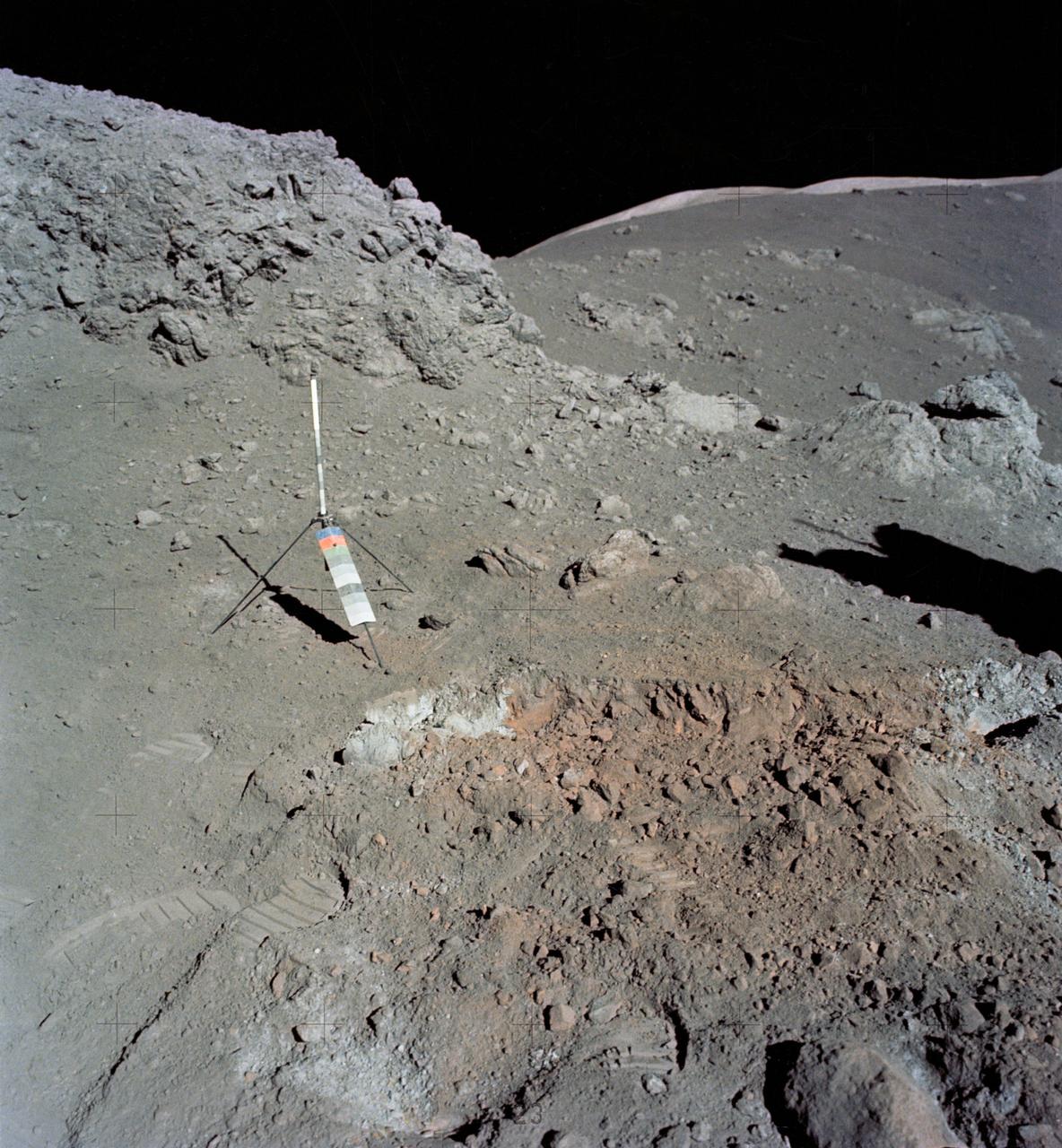
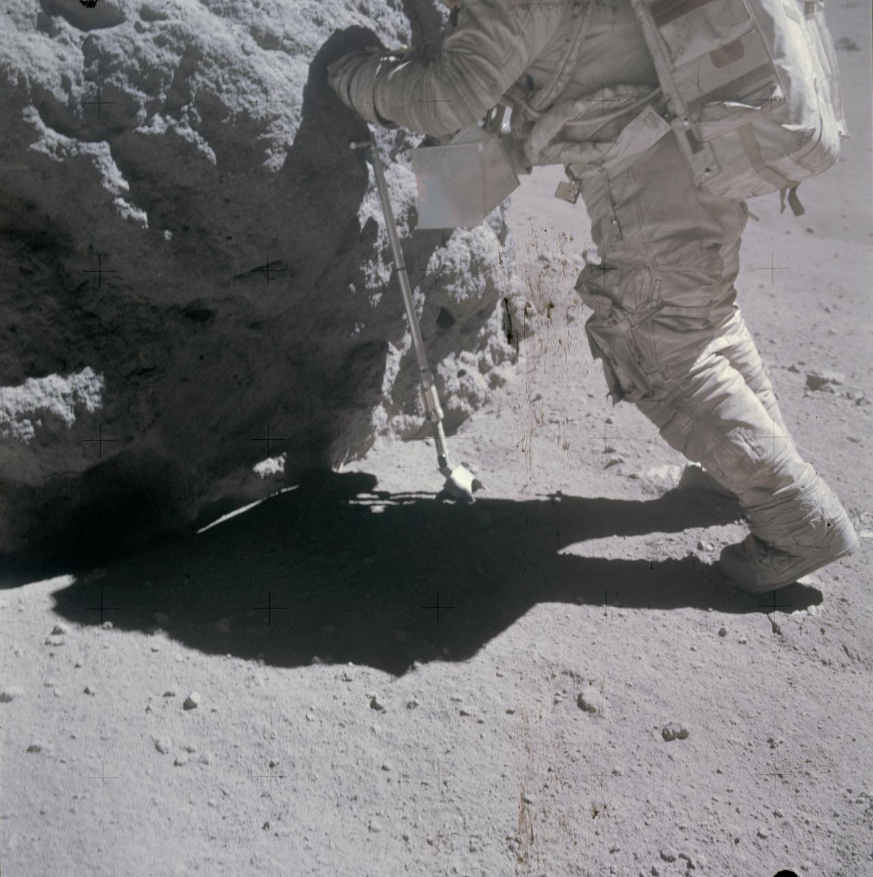
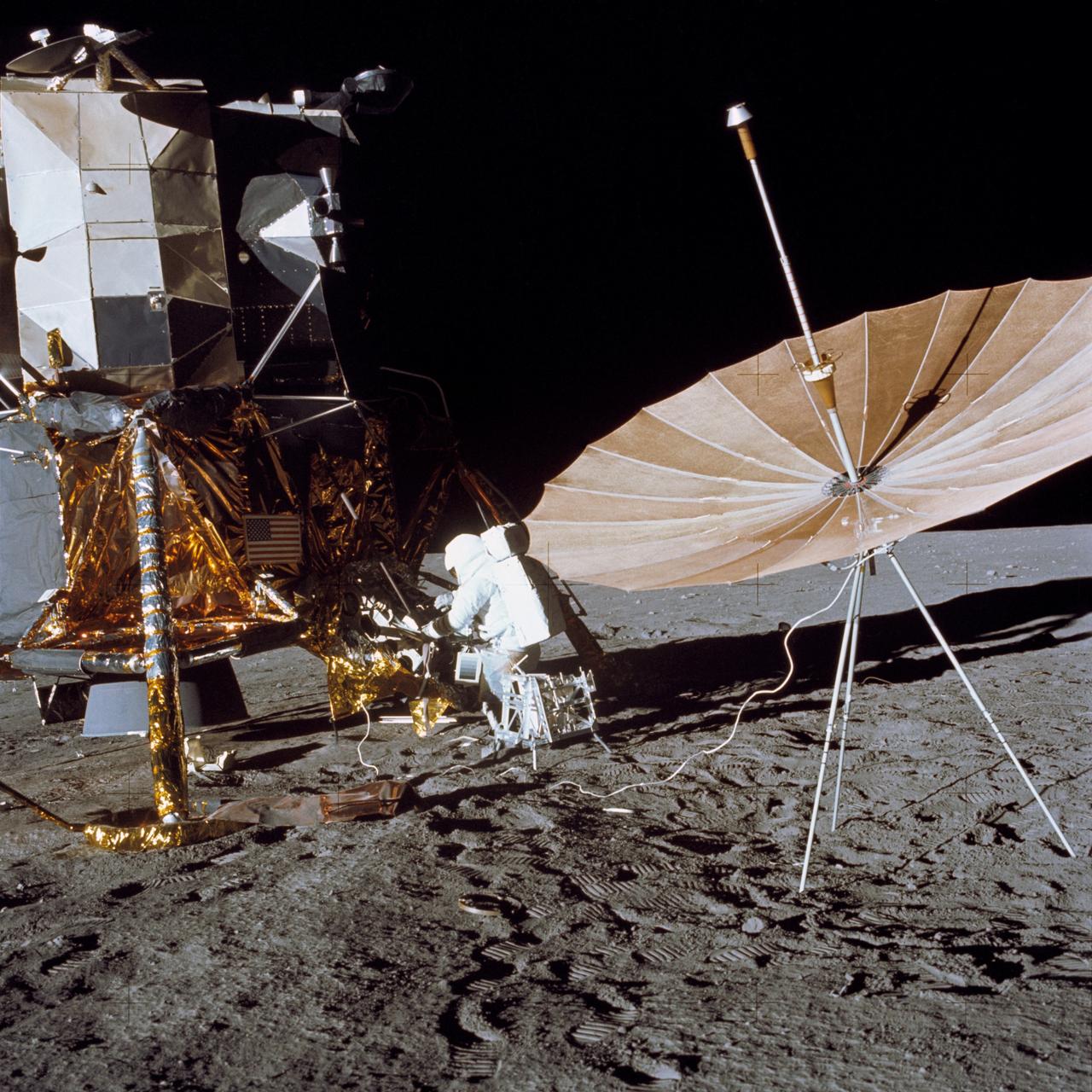
AS17-137-20990 (12 Dec. 1972) --- A view of the area at Station 4 (Shorty Crater) showing the now highly-publicized orange soil which the Apollo 17 crew members found on the moon during the second Apollo 17 extravehicular activity (EVA) at the Taurus-Littrow landing site. The tripod-like object is the gnomon and photometric chart assembly which is used as a photographic reference to establish local vertical sun angle, scale and lunar color. The gnomon is one of the Apollo lunar geology hand tools. While astronauts Eugene A. Cernan, commander, and Harrison H. Schmitt, lunar module pilot, descended in the Lunar Module (LM) "Challenger" to explore the Taurus-Littrow region of the moon, astronaut Ronald E. Evans, command module pilot, remained with the Command and Service Modules (CSM) "America" in lunar orbit. Schmitt was the crew man who first spotted the orange soil.
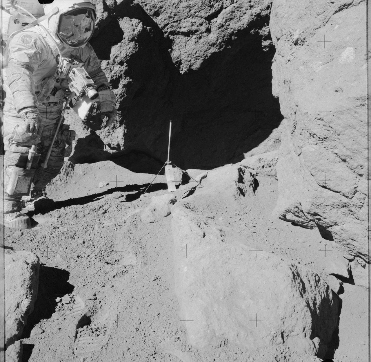
AS17-141-21608 (13 Dec. 1972) --- Astronaut Eugene A. Cernan stands near an over-hanging rock during the third Apollo 17 lunar surface extravehicular activity (EVA) at the Taurus-Littrow landing site. Scientist-astronaut Harrison H. Schmitt took this photograph. The tripod-like object just outside the shaded area is the gnomon and photometric chart assembly which is used as a photographic reference to establish local vertical sun angle, scale and lunar color. The gnomon is one of the Apollo Lunar Geology Hand Tools. While astronauts Cernan and Schmitt descended in the Lunar Module "Challenger" to explore the moon, astronaut Ronald E. Evans remained with the Apollo 17 Command and Service Modules in lunar orbit.

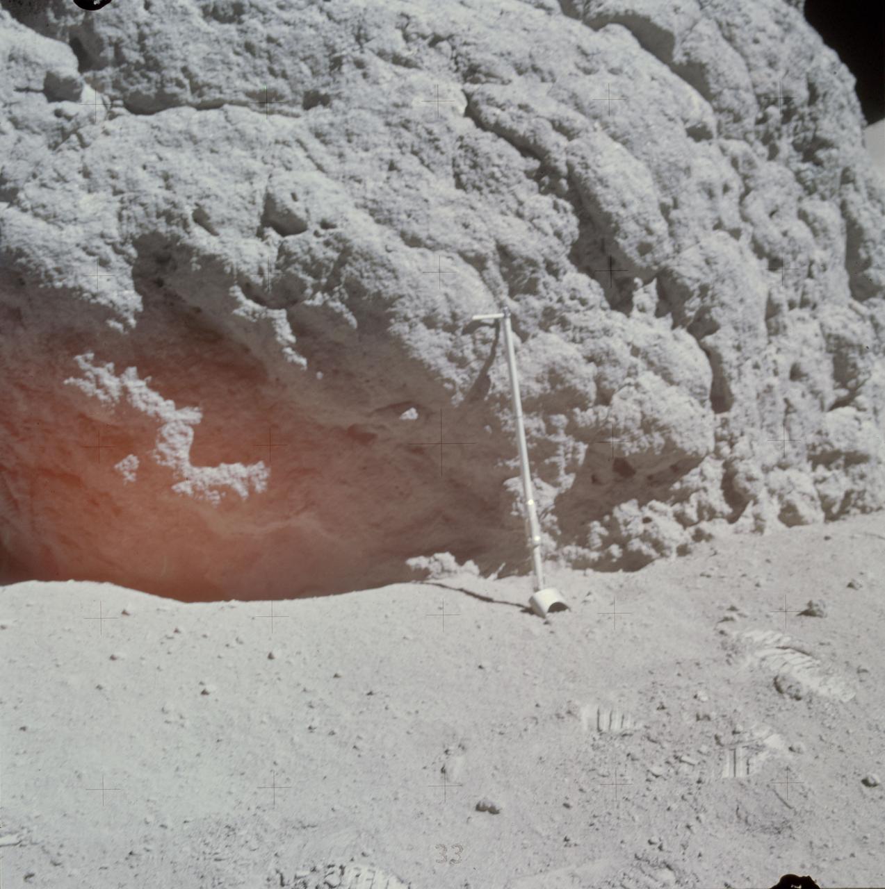
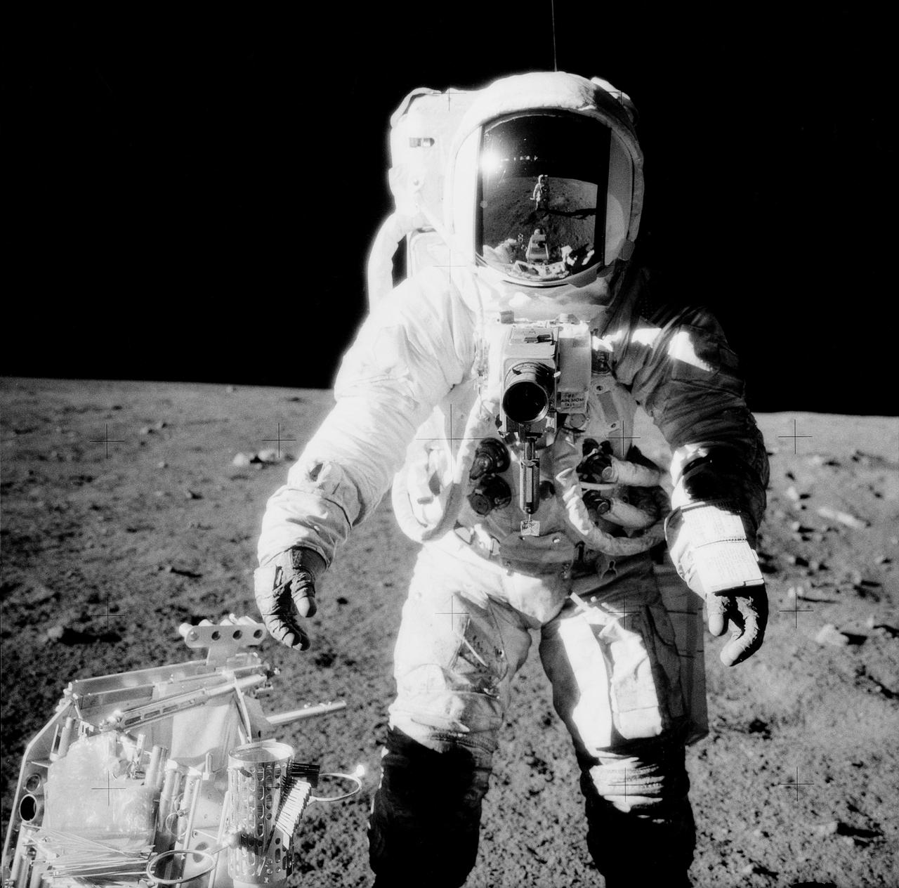
AS17-145-22157 (12 Dec. 1972) --- Scientist-astronaut Harrison Schmitt, Apollo 17 lunar module pilot, uses an adjustable sampling scoop to retrieve lunar samples during the second Apollo 17 extravehicular activity (EVA), at Station 5 at the Taurus-Littrow landing site. A gnomon is atop the large rock in the foreground. The gnomon is a stadia rod mounted on a tripod, and serves as an indicator of the gravitational vector and provides accurate vertical reference and calibrated length for determining size and position of objects in near-field photographs. The color scale of blue, orange and green is used to accurately determine color for photography. The rod of it is 18 inches long. The scoop Dr. Schmitt is using is 11 3/4 inches long and is attached to a tool extension which adds a potential 30 inches of length to the scoop. The pan portion, obscured in this view, has a flat bottom, flanged on both sides with a partial cover on the top. It is used to retrieve sand, dust and lunar samples too small for the tongs, another geological tool used by the astronauts. The pan and the adjusting mechanism are made of stainless steel and the handle is made of aluminum. Within the foreground of this scene, three lunar samples were taken--numbers 75060, 75075 and 75080. Astronaut Eugene A. Cernan, crew commander, was using a 60mm lens on the 70mm Hasselblad camera and type SO-368 film to take this photograph.
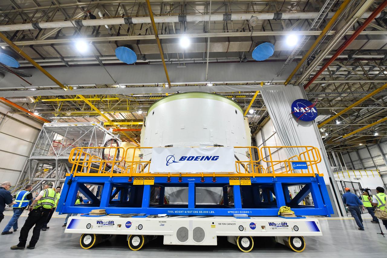
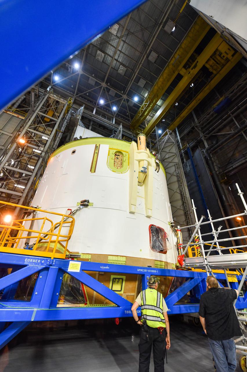
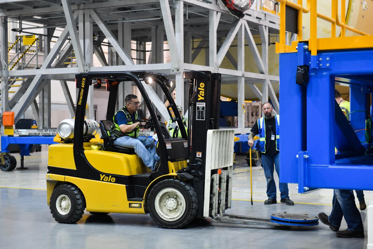
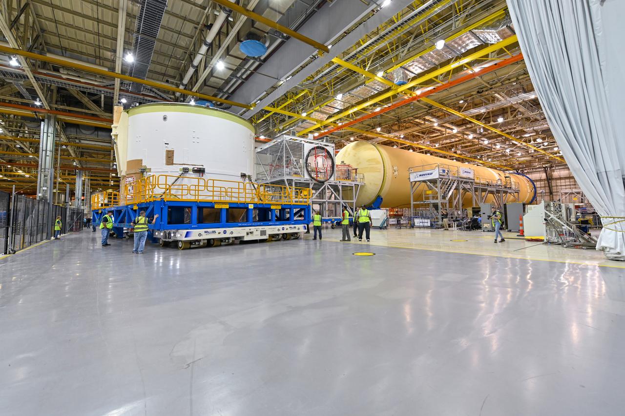
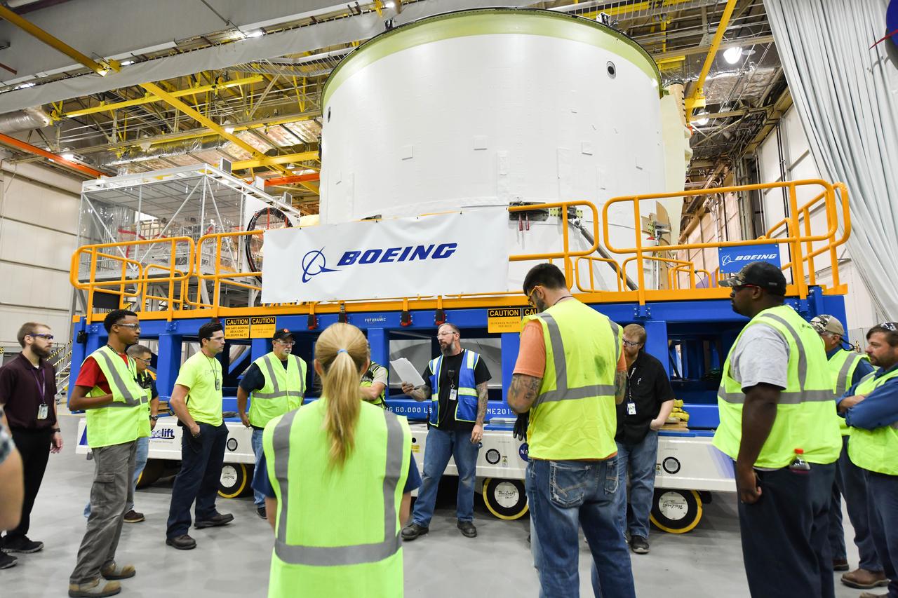
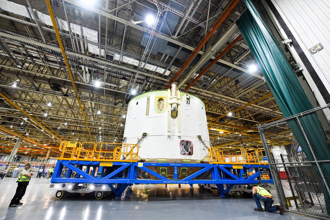
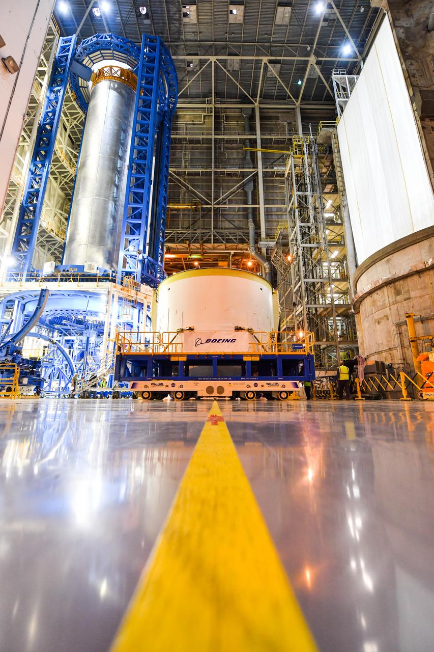
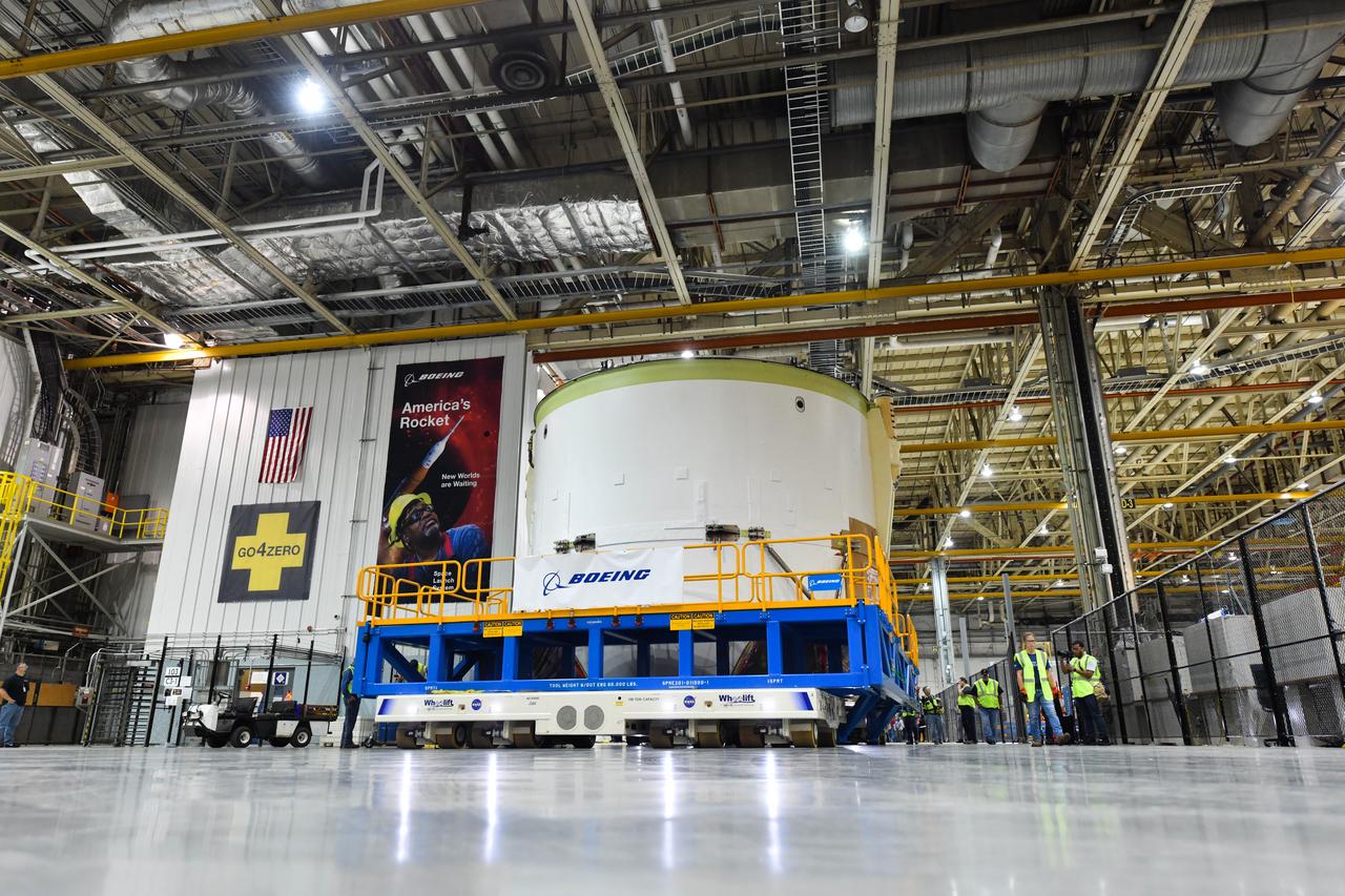
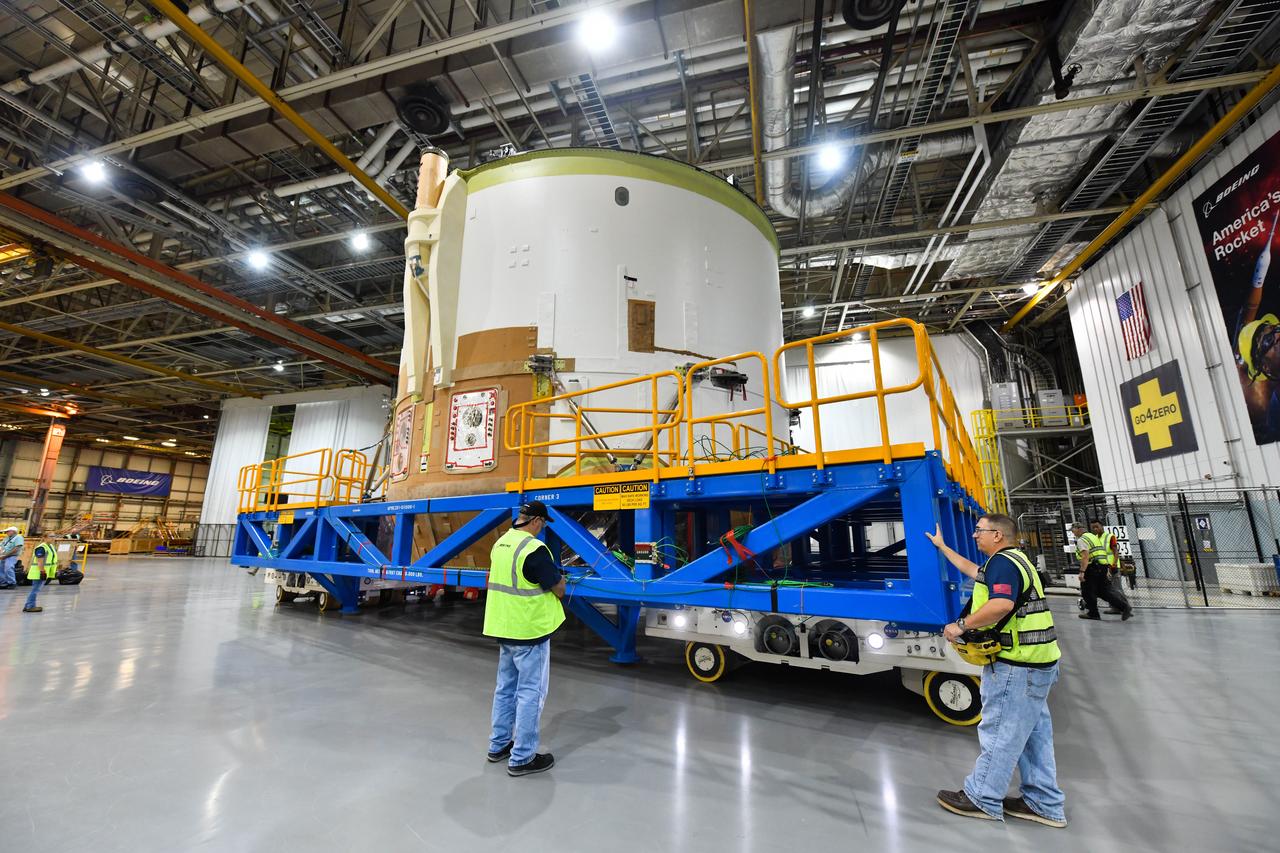
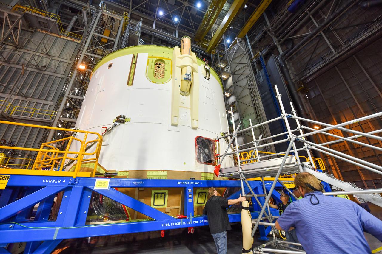
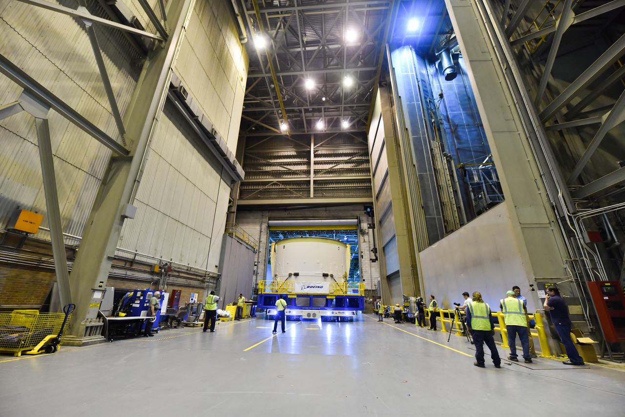
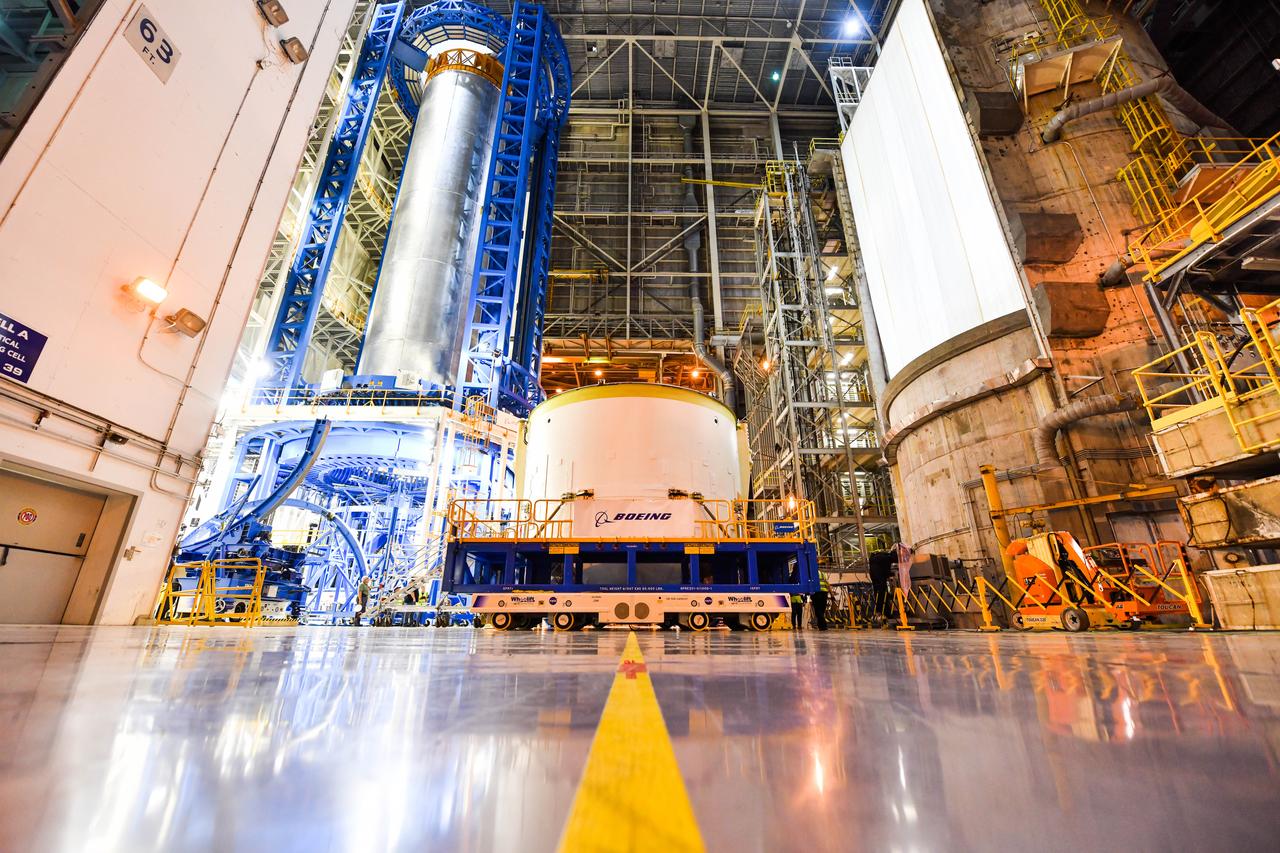
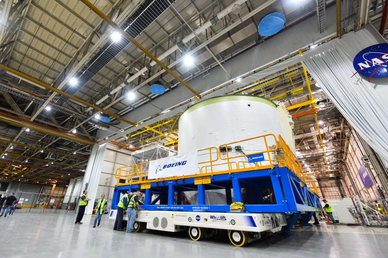
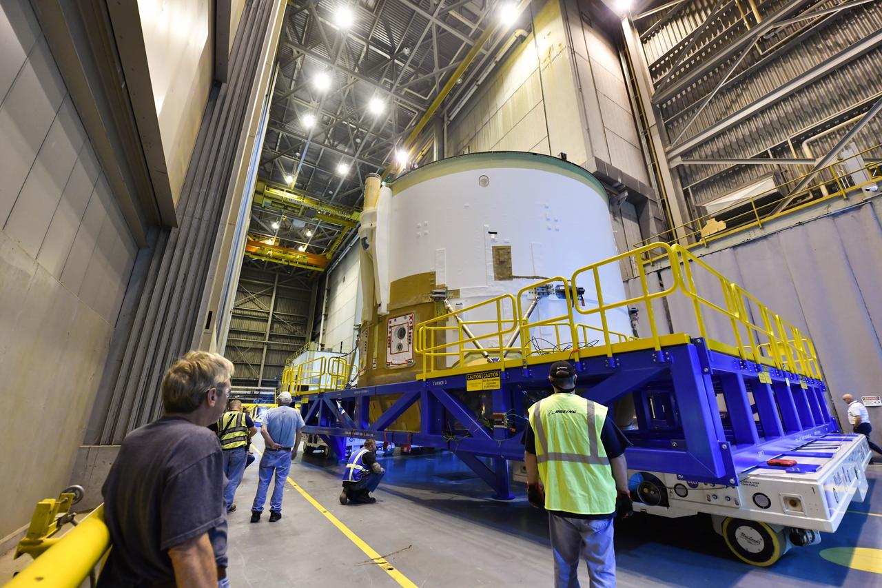
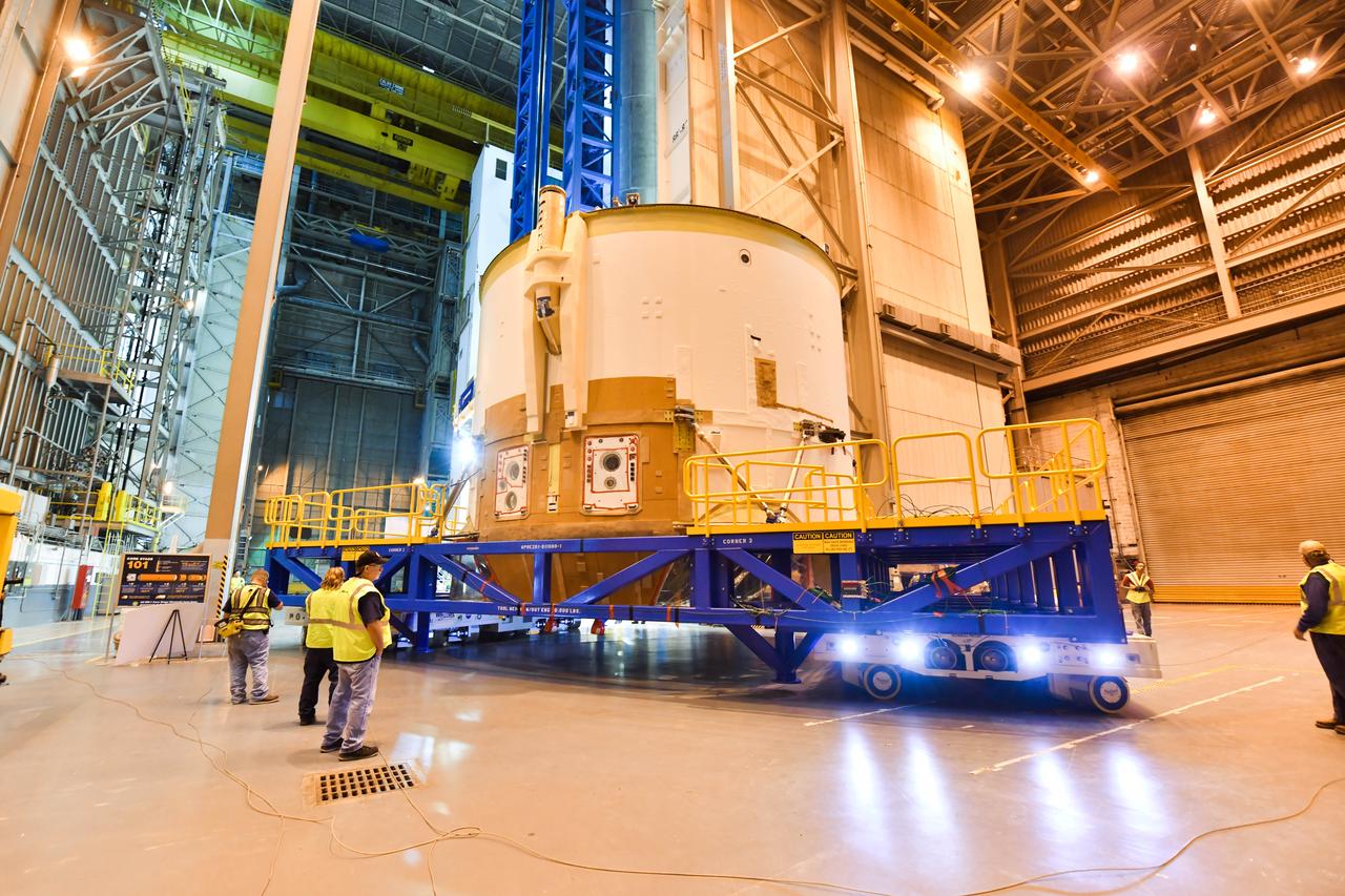
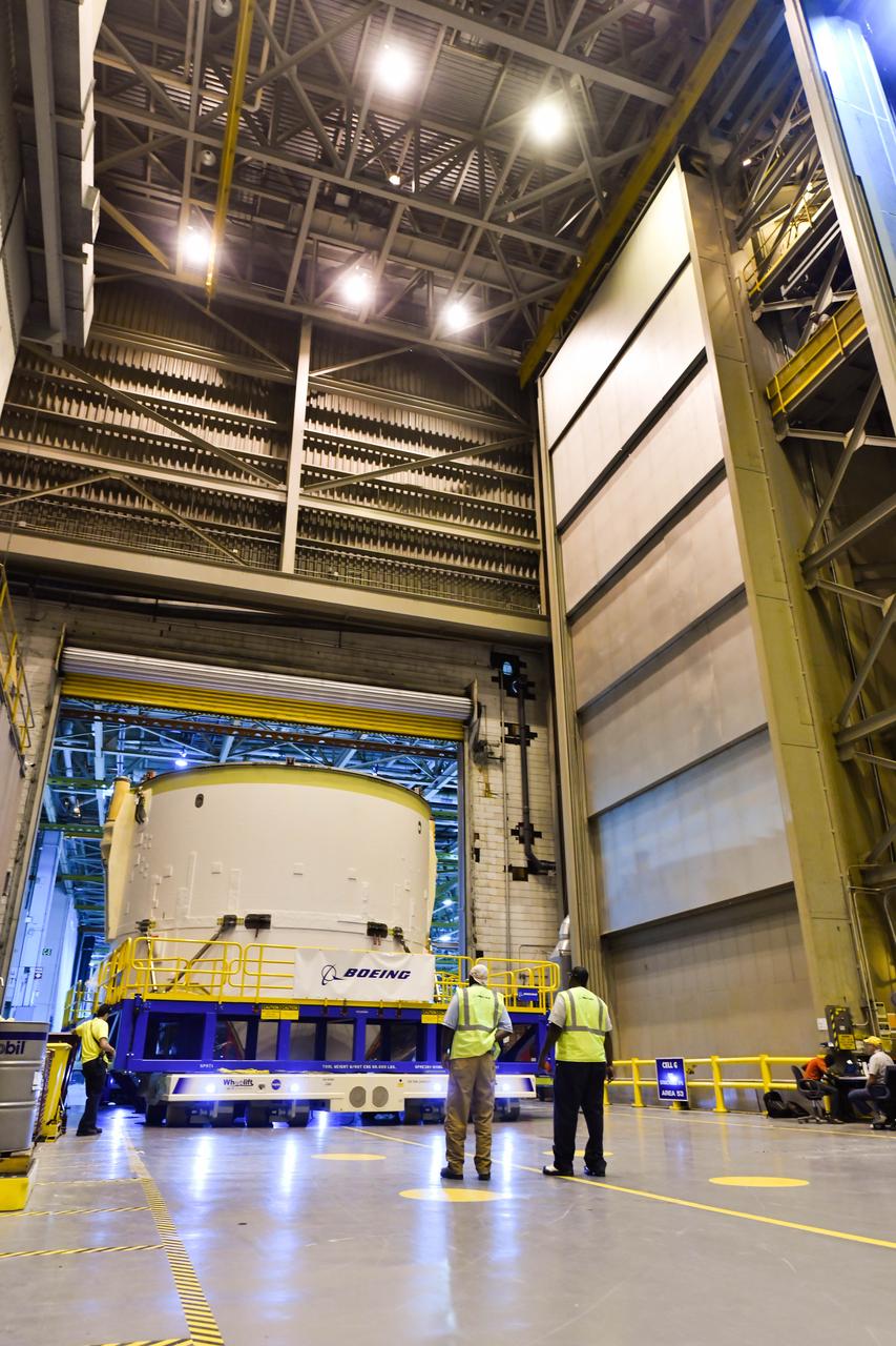
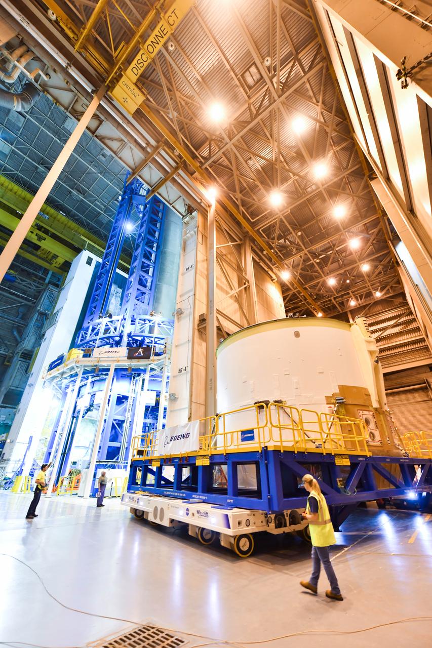
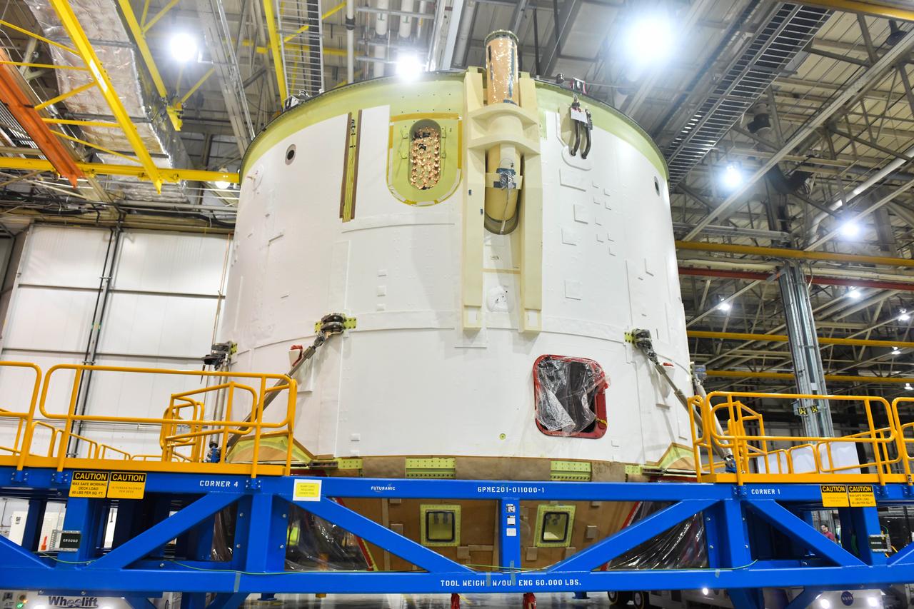
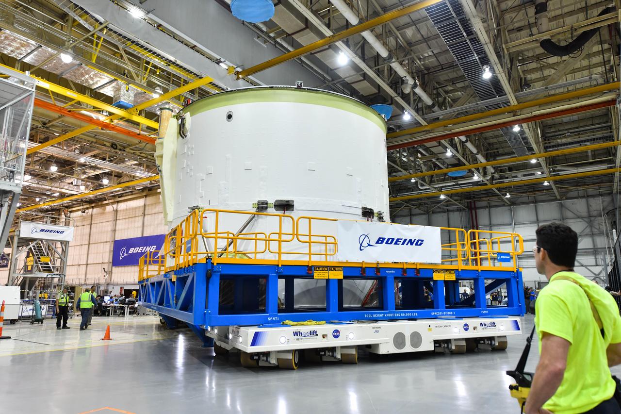
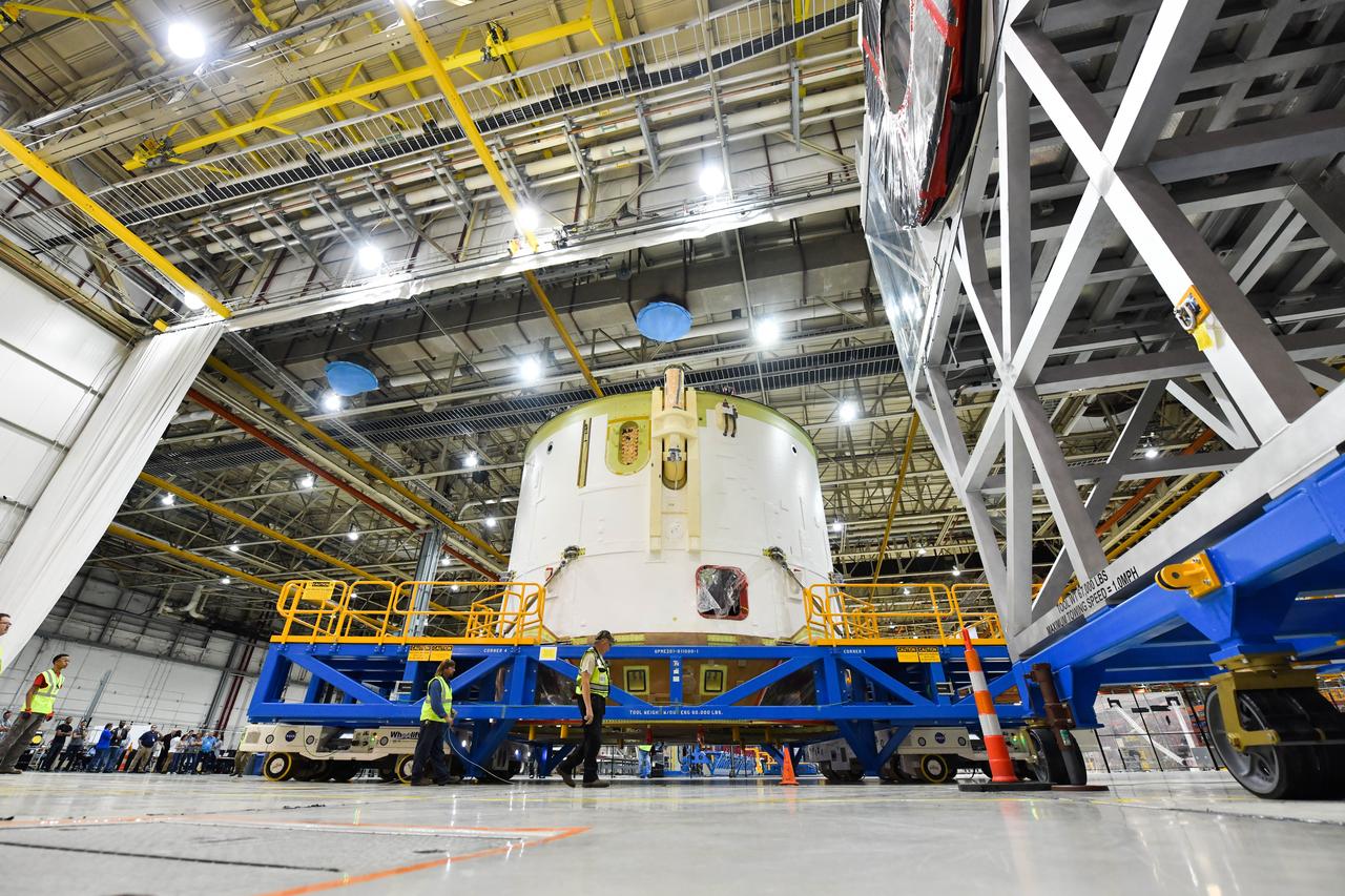
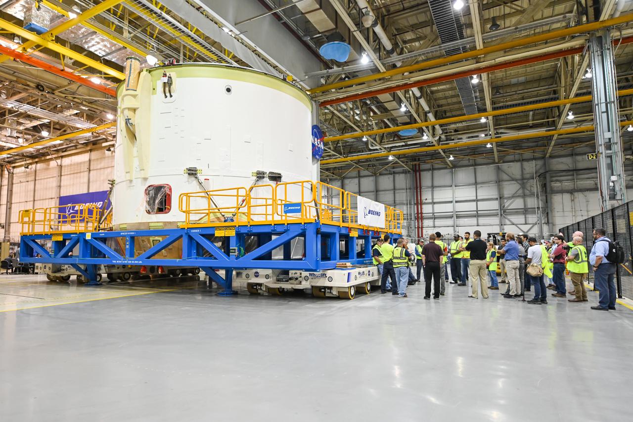
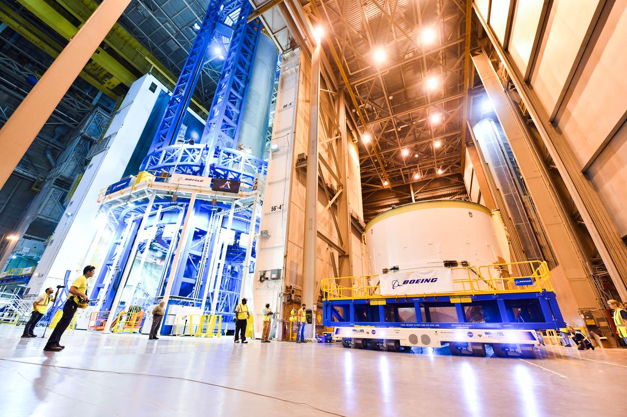
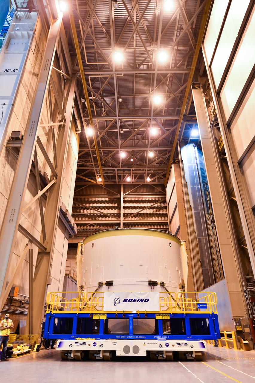
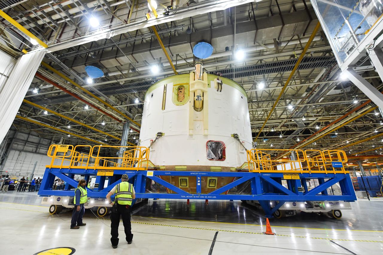
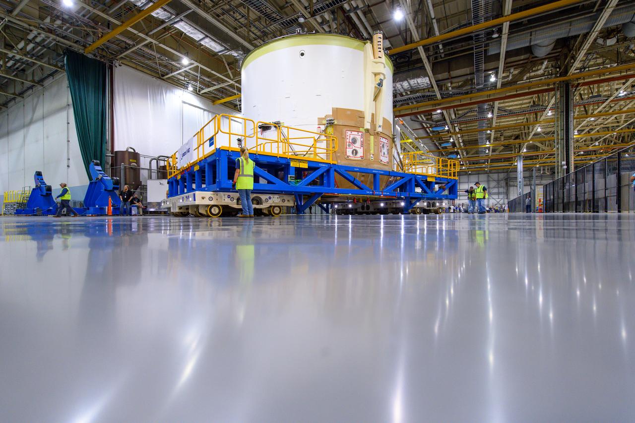
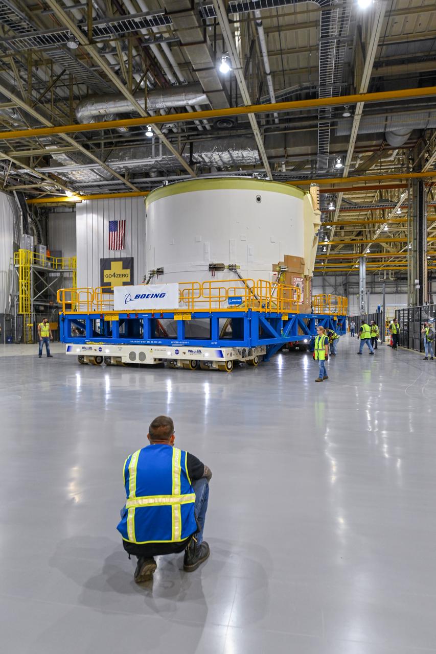
Technicians at NASA’s Michoud Assembly Facility in New Orleans moved the engine section for NASA’s Space Launch System (SLS) rocket to another part of the facility on Sept. 3 to prepare it for joining to the rest of the rocket’s core stage. The engine section, which comprises the lowest portion of the 212-foot-tall stage, is the last major component to be horizontally integrated to the core stage. Michoud crews completed assembly on the flight hardware that will be used for Artemis I, the first lunar mission of SLS and NASA’s Orion spacecraft, on Aug. 29. NASA and Boeing engineers removed the scaffolding surrounding the hardware to use a special tool to properly position the engine section for its attachment to the rest of the stage. The core stage’s two liquid propellant tanks and four RS-25 engines will produce more than 2 million pounds of thrust to send the SLS rocket and Orion on the Artemis lunar missions. The engine section houses the four RS-25 engines and includes vital systems for mounting, controlling and delivering fuel form the propellant tanks to the rocket’s engines. Offering more payload mass, volume capability and energy to speed missions through space, the SLS rocket, along with NASA’s Gateway in lunar orbit and Orion, is part of NASA’s backbone for deep space exploration and the Artemis lunar program. No other rocket is capable of carrying astronauts in Orion around the Moon in a single mission.
Technicians at NASA’s Michoud Assembly Facility in New Orleans moved the engine section for NASA’s Space Launch System (SLS) rocket to another part of the facility on Sept. 3 to prepare it for joining to the rest of the rocket’s core stage. The engine section, which comprises the lowest portion of the 212-foot-tall stage, is the last major component to be horizontally integrated to the core stage. Michoud crews completed assembly on the flight hardware that will be used for Artemis I, the first lunar mission of SLS and NASA’s Orion spacecraft, on Aug. 29. NASA and Boeing engineers removed the scaffolding surrounding the hardware to use a special tool to properly position the engine section for its attachment to the rest of the stage. The core stage’s two liquid propellant tanks and four RS-25 engines will produce more than 2 million pounds of thrust to send the SLS rocket and Orion on the Artemis lunar missions. The engine section houses the four RS-25 engines and includes vital systems for mounting, controlling and delivering fuel form the propellant tanks to the rocket’s engines. Offering more payload mass, volume capability and energy to speed missions through space, the SLS rocket, along with NASA’s Gateway in lunar orbit and Orion, is part of NASA’s backbone for deep space exploration and the Artemis lunar program. No other rocket is capable of carrying astronauts in Orion around the Moon in a single mission.
Technicians at NASA’s Michoud Assembly Facility in New Orleans moved the engine section for NASA’s Space Launch System (SLS) rocket to another part of the facility on Sept. 3 to prepare it for joining to the rest of the rocket’s core stage. The engine section, which comprises the lowest portion of the 212-foot-tall stage, is the last major component to be horizontally integrated to the core stage. Michoud crews completed assembly on the flight hardware that will be used for Artemis I, the first lunar mission of SLS and NASA’s Orion spacecraft, on Aug. 29. NASA and Boeing engineers removed the scaffolding surrounding the hardware to use a special tool to properly position the engine section for its attachment to the rest of the stage. The core stage’s two liquid propellant tanks and four RS-25 engines will produce more than 2 million pounds of thrust to send the SLS rocket and Orion on the Artemis lunar missions. The engine section houses the four RS-25 engines and includes vital systems for mounting, controlling and delivering fuel form the propellant tanks to the rocket’s engines. Offering more payload mass, volume capability and energy to speed missions through space, the SLS rocket, along with NASA’s Gateway in lunar orbit and Orion, is part of NASA’s backbone for deep space exploration and the Artemis lunar program. No other rocket is capable of carrying astronauts in Orion around the Moon in a single mission.
Technicians at NASA’s Michoud Assembly Facility in New Orleans moved the engine section for NASA’s Space Launch System (SLS) rocket to another part of the facility on Sept. 3 to prepare it for joining to the rest of the rocket’s core stage. The engine section, which comprises the lowest portion of the 212-foot-tall stage, is the last major component to be horizontally integrated to the core stage. Michoud crews completed assembly on the flight hardware that will be used for Artemis I, the first lunar mission of SLS and NASA’s Orion spacecraft, on Aug. 29. NASA and Boeing engineers removed the scaffolding surrounding the hardware to use a special tool to properly position the engine section for its attachment to the rest of the stage. The core stage’s two liquid propellant tanks and four RS-25 engines will produce more than 2 million pounds of thrust to send the SLS rocket and Orion on the Artemis lunar missions. The engine section houses the four RS-25 engines and includes vital systems for mounting, controlling and delivering fuel form the propellant tanks to the rocket’s engines. Offering more payload mass, volume capability and energy to speed missions through space, the SLS rocket, along with NASA’s Gateway in lunar orbit and Orion, is part of NASA’s backbone for deep space exploration and the Artemis lunar program. No other rocket is capable of carrying astronauts in Orion around the Moon in a single mission.
Technicians at NASA’s Michoud Assembly Facility in New Orleans moved the engine section for NASA’s Space Launch System (SLS) rocket to another part of the facility on Sept. 3 to prepare it for joining to the rest of the rocket’s core stage. The engine section, which comprises the lowest portion of the 212-foot-tall stage, is the last major component to be horizontally integrated to the core stage. Michoud crews completed assembly on the flight hardware that will be used for Artemis I, the first lunar mission of SLS and NASA’s Orion spacecraft, on Aug. 29. NASA and Boeing engineers removed the scaffolding surrounding the hardware to use a special tool to properly position the engine section for its attachment to the rest of the stage. The core stage’s two liquid propellant tanks and four RS-25 engines will produce more than 2 million pounds of thrust to send the SLS rocket and Orion on the Artemis lunar missions. The engine section houses the four RS-25 engines and includes vital systems for mounting, controlling and delivering fuel form the propellant tanks to the rocket’s engines. Offering more payload mass, volume capability and energy to speed missions through space, the SLS rocket, along with NASA’s Gateway in lunar orbit and Orion, is part of NASA’s backbone for deep space exploration and the Artemis lunar program. No other rocket is capable of carrying astronauts in Orion around the Moon in a single mission.
Technicians at NASA’s Michoud Assembly Facility in New Orleans moved the engine section for NASA’s Space Launch System (SLS) rocket to another part of the facility on Sept. 3 to prepare it for joining to the rest of the rocket’s core stage. The engine section, which comprises the lowest portion of the 212-foot-tall stage, is the last major component to be horizontally integrated to the core stage. Michoud crews completed assembly on the flight hardware that will be used for Artemis I, the first lunar mission of SLS and NASA’s Orion spacecraft, on Aug. 29. NASA and Boeing engineers removed the scaffolding surrounding the hardware to use a special tool to properly position the engine section for its attachment to the rest of the stage. The core stage’s two liquid propellant tanks and four RS-25 engines will produce more than 2 million pounds of thrust to send the SLS rocket and Orion on the Artemis lunar missions. The engine section houses the four RS-25 engines and includes vital systems for mounting, controlling and delivering fuel form the propellant tanks to the rocket’s engines. Offering more payload mass, volume capability and energy to speed missions through space, the SLS rocket, along with NASA’s Gateway in lunar orbit and Orion, is part of NASA’s backbone for deep space exploration and the Artemis lunar program. No other rocket is capable of carrying astronauts in Orion around the Moon in a single mission.
Technicians at NASA’s Michoud Assembly Facility in New Orleans moved the engine section for NASA’s Space Launch System (SLS) rocket to another part of the facility on Sept. 3 to prepare it for joining to the rest of the rocket’s core stage. The engine section, which comprises the lowest portion of the 212-foot-tall stage, is the last major component to be horizontally integrated to the core stage. Michoud crews completed assembly on the flight hardware that will be used for Artemis I, the first lunar mission of SLS and NASA’s Orion spacecraft, on Aug. 29. NASA and Boeing engineers removed the scaffolding surrounding the hardware to use a special tool to properly position the engine section for its attachment to the rest of the stage. The core stage’s two liquid propellant tanks and four RS-25 engines will produce more than 2 million pounds of thrust to send the SLS rocket and Orion on the Artemis lunar missions. The engine section houses the four RS-25 engines and includes vital systems for mounting, controlling and delivering fuel form the propellant tanks to the rocket’s engines. Offering more payload mass, volume capability and energy to speed missions through space, the SLS rocket, along with NASA’s Gateway in lunar orbit and Orion, is part of NASA’s backbone for deep space exploration and the Artemis lunar program. No other rocket is capable of carrying astronauts in Orion around the Moon in a single mission.
Technicians at NASA’s Michoud Assembly Facility in New Orleans moved the engine section for NASA’s Space Launch System (SLS) rocket to another part of the facility on Sept. 3 to prepare it for joining to the rest of the rocket’s core stage. The engine section, which comprises the lowest portion of the 212-foot-tall stage, is the last major component to be horizontally integrated to the core stage. Michoud crews completed assembly on the flight hardware that will be used for Artemis I, the first lunar mission of SLS and NASA’s Orion spacecraft, on Aug. 29. NASA and Boeing engineers removed the scaffolding surrounding the hardware to use a special tool to properly position the engine section for its attachment to the rest of the stage. The core stage’s two liquid propellant tanks and four RS-25 engines will produce more than 2 million pounds of thrust to send the SLS rocket and Orion on the Artemis lunar missions. The engine section houses the four RS-25 engines and includes vital systems for mounting, controlling and delivering fuel form the propellant tanks to the rocket’s engines. Offering more payload mass, volume capability and energy to speed missions through space, the SLS rocket, along with NASA’s Gateway in lunar orbit and Orion, is part of NASA’s backbone for deep space exploration and the Artemis lunar program. No other rocket is capable of carrying astronauts in Orion around the Moon in a single mission.
Technicians at NASA’s Michoud Assembly Facility in New Orleans moved the engine section for NASA’s Space Launch System (SLS) rocket to another part of the facility on Sept. 3 to prepare it for joining to the rest of the rocket’s core stage. The engine section, which comprises the lowest portion of the 212-foot-tall stage, is the last major component to be horizontally integrated to the core stage. Michoud crews completed assembly on the flight hardware that will be used for Artemis I, the first lunar mission of SLS and NASA’s Orion spacecraft, on Aug. 29. NASA and Boeing engineers removed the scaffolding surrounding the hardware to use a special tool to properly position the engine section for its attachment to the rest of the stage. The core stage’s two liquid propellant tanks and four RS-25 engines will produce more than 2 million pounds of thrust to send the SLS rocket and Orion on the Artemis lunar missions. The engine section houses the four RS-25 engines and includes vital systems for mounting, controlling and delivering fuel form the propellant tanks to the rocket’s engines. Offering more payload mass, volume capability and energy to speed missions through space, the SLS rocket, along with NASA’s Gateway in lunar orbit and Orion, is part of NASA’s backbone for deep space exploration and the Artemis lunar program. No other rocket is capable of carrying astronauts in Orion around the Moon in a single mission.
Technicians at NASA’s Michoud Assembly Facility in New Orleans moved the engine section for NASA’s Space Launch System (SLS) rocket to another part of the facility on Sept. 3 to prepare it for joining to the rest of the rocket’s core stage. The engine section, which comprises the lowest portion of the 212-foot-tall stage, is the last major component to be horizontally integrated to the core stage. Michoud crews completed assembly on the flight hardware that will be used for Artemis I, the first lunar mission of SLS and NASA’s Orion spacecraft, on Aug. 29. NASA and Boeing engineers removed the scaffolding surrounding the hardware to use a special tool to properly position the engine section for its attachment to the rest of the stage. The core stage’s two liquid propellant tanks and four RS-25 engines will produce more than 2 million pounds of thrust to send the SLS rocket and Orion on the Artemis lunar missions. The engine section houses the four RS-25 engines and includes vital systems for mounting, controlling and delivering fuel form the propellant tanks to the rocket’s engines. Offering more payload mass, volume capability and energy to speed missions through space, the SLS rocket, along with NASA’s Gateway in lunar orbit and Orion, is part of NASA’s backbone for deep space exploration and the Artemis lunar program. No other rocket is capable of carrying astronauts in Orion around the Moon in a single mission.
Technicians at NASA’s Michoud Assembly Facility in New Orleans moved the engine section for NASA’s Space Launch System (SLS) rocket to another part of the facility on Sept. 3 to prepare it for joining to the rest of the rocket’s core stage. The engine section, which comprises the lowest portion of the 212-foot-tall stage, is the last major component to be horizontally integrated to the core stage. Michoud crews completed assembly on the flight hardware that will be used for Artemis I, the first lunar mission of SLS and NASA’s Orion spacecraft, on Aug. 29. NASA and Boeing engineers removed the scaffolding surrounding the hardware to use a special tool to properly position the engine section for its attachment to the rest of the stage. The core stage’s two liquid propellant tanks and four RS-25 engines will produce more than 2 million pounds of thrust to send the SLS rocket and Orion on the Artemis lunar missions. The engine section houses the four RS-25 engines and includes vital systems for mounting, controlling and delivering fuel form the propellant tanks to the rocket’s engines. Offering more payload mass, volume capability and energy to speed missions through space, the SLS rocket, along with NASA’s Gateway in lunar orbit and Orion, is part of NASA’s backbone for deep space exploration and the Artemis lunar program. No other rocket is capable of carrying astronauts in Orion around the Moon in a single mission.
Technicians at NASA’s Michoud Assembly Facility in New Orleans moved the engine section for NASA’s Space Launch System (SLS) rocket to another part of the facility on Sept. 3 to prepare it for joining to the rest of the rocket’s core stage. The engine section, which comprises the lowest portion of the 212-foot-tall stage, is the last major component to be horizontally integrated to the core stage. Michoud crews completed assembly on the flight hardware that will be used for Artemis I, the first lunar mission of SLS and NASA’s Orion spacecraft, on Aug. 29. NASA and Boeing engineers removed the scaffolding surrounding the hardware to use a special tool to properly position the engine section for its attachment to the rest of the stage. The core stage’s two liquid propellant tanks and four RS-25 engines will produce more than 2 million pounds of thrust to send the SLS rocket and Orion on the Artemis lunar missions. The engine section houses the four RS-25 engines and includes vital systems for mounting, controlling and delivering fuel form the propellant tanks to the rocket’s engines. Offering more payload mass, volume capability and energy to speed missions through space, the SLS rocket, along with NASA’s Gateway in lunar orbit and Orion, is part of NASA’s backbone for deep space exploration and the Artemis lunar program. No other rocket is capable of carrying astronauts in Orion around the Moon in a single mission.
Technicians at NASA’s Michoud Assembly Facility in New Orleans moved the engine section for NASA’s Space Launch System (SLS) rocket to another part of the facility on Sept. 3 to prepare it for joining to the rest of the rocket’s core stage. The engine section, which comprises the lowest portion of the 212-foot-tall stage, is the last major component to be horizontally integrated to the core stage. Michoud crews completed assembly on the flight hardware that will be used for Artemis I, the first lunar mission of SLS and NASA’s Orion spacecraft, on Aug. 29. NASA and Boeing engineers removed the scaffolding surrounding the hardware to use a special tool to properly position the engine section for its attachment to the rest of the stage. The core stage’s two liquid propellant tanks and four RS-25 engines will produce more than 2 million pounds of thrust to send the SLS rocket and Orion on the Artemis lunar missions. The engine section houses the four RS-25 engines and includes vital systems for mounting, controlling and delivering fuel form the propellant tanks to the rocket’s engines. Offering more payload mass, volume capability and energy to speed missions through space, the SLS rocket, along with NASA’s Gateway in lunar orbit and Orion, is part of NASA’s backbone for deep space exploration and the Artemis lunar program. No other rocket is capable of carrying astronauts in Orion around the Moon in a single mission.
Technicians at NASA’s Michoud Assembly Facility in New Orleans moved the engine section for NASA’s Space Launch System (SLS) rocket to another part of the facility on Sept. 3 to prepare it for joining to the rest of the rocket’s core stage. The engine section, which comprises the lowest portion of the 212-foot-tall stage, is the last major component to be horizontally integrated to the core stage. Michoud crews completed assembly on the flight hardware that will be used for Artemis I, the first lunar mission of SLS and NASA’s Orion spacecraft, on Aug. 29. NASA and Boeing engineers removed the scaffolding surrounding the hardware to use a special tool to properly position the engine section for its attachment to the rest of the stage. The core stage’s two liquid propellant tanks and four RS-25 engines will produce more than 2 million pounds of thrust to send the SLS rocket and Orion on the Artemis lunar missions. The engine section houses the four RS-25 engines and includes vital systems for mounting, controlling and delivering fuel form the propellant tanks to the rocket’s engines. Offering more payload mass, volume capability and energy to speed missions through space, the SLS rocket, along with NASA’s Gateway in lunar orbit and Orion, is part of NASA’s backbone for deep space exploration and the Artemis lunar program. No other rocket is capable of carrying astronauts in Orion around the Moon in a single mission.
Technicians at NASA’s Michoud Assembly Facility in New Orleans moved the engine section for NASA’s Space Launch System (SLS) rocket to another part of the facility on Sept. 3 to prepare it for joining to the rest of the rocket’s core stage. The engine section, which comprises the lowest portion of the 212-foot-tall stage, is the last major component to be horizontally integrated to the core stage. Michoud crews completed assembly on the flight hardware that will be used for Artemis I, the first lunar mission of SLS and NASA’s Orion spacecraft, on Aug. 29. NASA and Boeing engineers removed the scaffolding surrounding the hardware to use a special tool to properly position the engine section for its attachment to the rest of the stage. The core stage’s two liquid propellant tanks and four RS-25 engines will produce more than 2 million pounds of thrust to send the SLS rocket and Orion on the Artemis lunar missions. The engine section houses the four RS-25 engines and includes vital systems for mounting, controlling and delivering fuel form the propellant tanks to the rocket’s engines. Offering more payload mass, volume capability and energy to speed missions through space, the SLS rocket, along with NASA’s Gateway in lunar orbit and Orion, is part of NASA’s backbone for deep space exploration and the Artemis lunar program. No other rocket is capable of carrying astronauts in Orion around the Moon in a single mission.
Technicians at NASA’s Michoud Assembly Facility in New Orleans moved the engine section for NASA’s Space Launch System (SLS) rocket to another part of the facility on Sept. 3 to prepare it for joining to the rest of the rocket’s core stage. The engine section, which comprises the lowest portion of the 212-foot-tall stage, is the last major component to be horizontally integrated to the core stage. Michoud crews completed assembly on the flight hardware that will be used for Artemis I, the first lunar mission of SLS and NASA’s Orion spacecraft, on Aug. 29. NASA and Boeing engineers removed the scaffolding surrounding the hardware to use a special tool to properly position the engine section for its attachment to the rest of the stage. The core stage’s two liquid propellant tanks and four RS-25 engines will produce more than 2 million pounds of thrust to send the SLS rocket and Orion on the Artemis lunar missions. The engine section houses the four RS-25 engines and includes vital systems for mounting, controlling and delivering fuel form the propellant tanks to the rocket’s engines. Offering more payload mass, volume capability and energy to speed missions through space, the SLS rocket, along with NASA’s Gateway in lunar orbit and Orion, is part of NASA’s backbone for deep space exploration and the Artemis lunar program. No other rocket is capable of carrying astronauts in Orion around the Moon in a single mission.
Technicians at NASA’s Michoud Assembly Facility in New Orleans moved the engine section for NASA’s Space Launch System (SLS) rocket to another part of the facility on Sept. 3 to prepare it for joining to the rest of the rocket’s core stage. The engine section, which comprises the lowest portion of the 212-foot-tall stage, is the last major component to be horizontally integrated to the core stage. Michoud crews completed assembly on the flight hardware that will be used for Artemis I, the first lunar mission of SLS and NASA’s Orion spacecraft, on Aug. 29. NASA and Boeing engineers removed the scaffolding surrounding the hardware to use a special tool to properly position the engine section for its attachment to the rest of the stage. The core stage’s two liquid propellant tanks and four RS-25 engines will produce more than 2 million pounds of thrust to send the SLS rocket and Orion on the Artemis lunar missions. The engine section houses the four RS-25 engines and includes vital systems for mounting, controlling and delivering fuel form the propellant tanks to the rocket’s engines. Offering more payload mass, volume capability and energy to speed missions through space, the SLS rocket, along with NASA’s Gateway in lunar orbit and Orion, is part of NASA’s backbone for deep space exploration and the Artemis lunar program. No other rocket is capable of carrying astronauts in Orion around the Moon in a single mission.
Technicians at NASA’s Michoud Assembly Facility in New Orleans moved the engine section for NASA’s Space Launch System (SLS) rocket to another part of the facility on Sept. 3 to prepare it for joining to the rest of the rocket’s core stage. The engine section, which comprises the lowest portion of the 212-foot-tall stage, is the last major component to be horizontally integrated to the core stage. Michoud crews completed assembly on the flight hardware that will be used for Artemis I, the first lunar mission of SLS and NASA’s Orion spacecraft, on Aug. 29. NASA and Boeing engineers removed the scaffolding surrounding the hardware to use a special tool to properly position the engine section for its attachment to the rest of the stage. The core stage’s two liquid propellant tanks and four RS-25 engines will produce more than 2 million pounds of thrust to send the SLS rocket and Orion on the Artemis lunar missions. The engine section houses the four RS-25 engines and includes vital systems for mounting, controlling and delivering fuel form the propellant tanks to the rocket’s engines. Offering more payload mass, volume capability and energy to speed missions through space, the SLS rocket, along with NASA’s Gateway in lunar orbit and Orion, is part of NASA’s backbone for deep space exploration and the Artemis lunar program. No other rocket is capable of carrying astronauts in Orion around the Moon in a single mission.
Technicians at NASA’s Michoud Assembly Facility in New Orleans moved the engine section for NASA’s Space Launch System (SLS) rocket to another part of the facility on Sept. 3 to prepare it for joining to the rest of the rocket’s core stage. The engine section, which comprises the lowest portion of the 212-foot-tall stage, is the last major component to be horizontally integrated to the core stage. Michoud crews completed assembly on the flight hardware that will be used for Artemis I, the first lunar mission of SLS and NASA’s Orion spacecraft, on Aug. 29. NASA and Boeing engineers removed the scaffolding surrounding the hardware to use a special tool to properly position the engine section for its attachment to the rest of the stage. The core stage’s two liquid propellant tanks and four RS-25 engines will produce more than 2 million pounds of thrust to send the SLS rocket and Orion on the Artemis lunar missions. The engine section houses the four RS-25 engines and includes vital systems for mounting, controlling and delivering fuel form the propellant tanks to the rocket’s engines. Offering more payload mass, volume capability and energy to speed missions through space, the SLS rocket, along with NASA’s Gateway in lunar orbit and Orion, is part of NASA’s backbone for deep space exploration and the Artemis lunar program. No other rocket is capable of carrying astronauts in Orion around the Moon in a single mission.
Technicians at NASA’s Michoud Assembly Facility in New Orleans moved the engine section for NASA’s Space Launch System (SLS) rocket to another part of the facility on Sept. 3 to prepare it for joining to the rest of the rocket’s core stage. The engine section, which comprises the lowest portion of the 212-foot-tall stage, is the last major component to be horizontally integrated to the core stage. Michoud crews completed assembly on the flight hardware that will be used for Artemis I, the first lunar mission of SLS and NASA’s Orion spacecraft, on Aug. 29. NASA and Boeing engineers removed the scaffolding surrounding the hardware to use a special tool to properly position the engine section for its attachment to the rest of the stage. The core stage’s two liquid propellant tanks and four RS-25 engines will produce more than 2 million pounds of thrust to send the SLS rocket and Orion on the Artemis lunar missions. The engine section houses the four RS-25 engines and includes vital systems for mounting, controlling and delivering fuel form the propellant tanks to the rocket’s engines. Offering more payload mass, volume capability and energy to speed missions through space, the SLS rocket, along with NASA’s Gateway in lunar orbit and Orion, is part of NASA’s backbone for deep space exploration and the Artemis lunar program. No other rocket is capable of carrying astronauts in Orion around the Moon in a single mission.
Technicians at NASA’s Michoud Assembly Facility in New Orleans moved the engine section for NASA’s Space Launch System (SLS) rocket to another part of the facility on Sept. 3 to prepare it for joining to the rest of the rocket’s core stage. The engine section, which comprises the lowest portion of the 212-foot-tall stage, is the last major component to be horizontally integrated to the core stage. Michoud crews completed assembly on the flight hardware that will be used for Artemis I, the first lunar mission of SLS and NASA’s Orion spacecraft, on Aug. 29. NASA and Boeing engineers removed the scaffolding surrounding the hardware to use a special tool to properly position the engine section for its attachment to the rest of the stage. The core stage’s two liquid propellant tanks and four RS-25 engines will produce more than 2 million pounds of thrust to send the SLS rocket and Orion on the Artemis lunar missions. The engine section houses the four RS-25 engines and includes vital systems for mounting, controlling and delivering fuel form the propellant tanks to the rocket’s engines. Offering more payload mass, volume capability and energy to speed missions through space, the SLS rocket, along with NASA’s Gateway in lunar orbit and Orion, is part of NASA’s backbone for deep space exploration and the Artemis lunar program. No other rocket is capable of carrying astronauts in Orion around the Moon in a single mission.
Technicians at NASA’s Michoud Assembly Facility in New Orleans moved the engine section for NASA’s Space Launch System (SLS) rocket to another part of the facility on Sept. 3 to prepare it for joining to the rest of the rocket’s core stage. The engine section, which comprises the lowest portion of the 212-foot-tall stage, is the last major component to be horizontally integrated to the core stage. Michoud crews completed assembly on the flight hardware that will be used for Artemis I, the first lunar mission of SLS and NASA’s Orion spacecraft, on Aug. 29. NASA and Boeing engineers removed the scaffolding surrounding the hardware to use a special tool to properly position the engine section for its attachment to the rest of the stage. The core stage’s two liquid propellant tanks and four RS-25 engines will produce more than 2 million pounds of thrust to send the SLS rocket and Orion on the Artemis lunar missions. The engine section houses the four RS-25 engines and includes vital systems for mounting, controlling and delivering fuel form the propellant tanks to the rocket’s engines. Offering more payload mass, volume capability and energy to speed missions through space, the SLS rocket, along with NASA’s Gateway in lunar orbit and Orion, is part of NASA’s backbone for deep space exploration and the Artemis lunar program. No other rocket is capable of carrying astronauts in Orion around the Moon in a single mission.
Technicians at NASA’s Michoud Assembly Facility in New Orleans moved the engine section for NASA’s Space Launch System (SLS) rocket to another part of the facility on Sept. 3 to prepare it for joining to the rest of the rocket’s core stage. The engine section, which comprises the lowest portion of the 212-foot-tall stage, is the last major component to be horizontally integrated to the core stage. Michoud crews completed assembly on the flight hardware that will be used for Artemis I, the first lunar mission of SLS and NASA’s Orion spacecraft, on Aug. 29. NASA and Boeing engineers removed the scaffolding surrounding the hardware to use a special tool to properly position the engine section for its attachment to the rest of the stage. The core stage’s two liquid propellant tanks and four RS-25 engines will produce more than 2 million pounds of thrust to send the SLS rocket and Orion on the Artemis lunar missions. The engine section houses the four RS-25 engines and includes vital systems for mounting, controlling and delivering fuel form the propellant tanks to the rocket’s engines. Offering more payload mass, volume capability and energy to speed missions through space, the SLS rocket, along with NASA’s Gateway in lunar orbit and Orion, is part of NASA’s backbone for deep space exploration and the Artemis lunar program. No other rocket is capable of carrying astronauts in Orion around the Moon in a single mission.
Technicians at NASA’s Michoud Assembly Facility in New Orleans moved the engine section for NASA’s Space Launch System (SLS) rocket to another part of the facility on Sept. 3 to prepare it for joining to the rest of the rocket’s core stage. The engine section, which comprises the lowest portion of the 212-foot-tall stage, is the last major component to be horizontally integrated to the core stage. Michoud crews completed assembly on the flight hardware that will be used for Artemis I, the first lunar mission of SLS and NASA’s Orion spacecraft, on Aug. 29. NASA and Boeing engineers removed the scaffolding surrounding the hardware to use a special tool to properly position the engine section for its attachment to the rest of the stage. The core stage’s two liquid propellant tanks and four RS-25 engines will produce more than 2 million pounds of thrust to send the SLS rocket and Orion on the Artemis lunar missions. The engine section houses the four RS-25 engines and includes vital systems for mounting, controlling and delivering fuel form the propellant tanks to the rocket’s engines. Offering more payload mass, volume capability and energy to speed missions through space, the SLS rocket, along with NASA’s Gateway in lunar orbit and Orion, is part of NASA’s backbone for deep space exploration and the Artemis lunar program. No other rocket is capable of carrying astronauts in Orion around the Moon in a single mission.
Technicians at NASA’s Michoud Assembly Facility in New Orleans moved the engine section for NASA’s Space Launch System (SLS) rocket to another part of the facility on Sept. 3 to prepare it for joining to the rest of the rocket’s core stage. The engine section, which comprises the lowest portion of the 212-foot-tall stage, is the last major component to be horizontally integrated to the core stage. Michoud crews completed assembly on the flight hardware that will be used for Artemis I, the first lunar mission of SLS and NASA’s Orion spacecraft, on Aug. 29. NASA and Boeing engineers removed the scaffolding surrounding the hardware to use a special tool to properly position the engine section for its attachment to the rest of the stage. The core stage’s two liquid propellant tanks and four RS-25 engines will produce more than 2 million pounds of thrust to send the SLS rocket and Orion on the Artemis lunar missions. The engine section houses the four RS-25 engines and includes vital systems for mounting, controlling and delivering fuel form the propellant tanks to the rocket’s engines. Offering more payload mass, volume capability and energy to speed missions through space, the SLS rocket, along with NASA’s Gateway in lunar orbit and Orion, is part of NASA’s backbone for deep space exploration and the Artemis lunar program. No other rocket is capable of carrying astronauts in Orion around the Moon in a single mission.
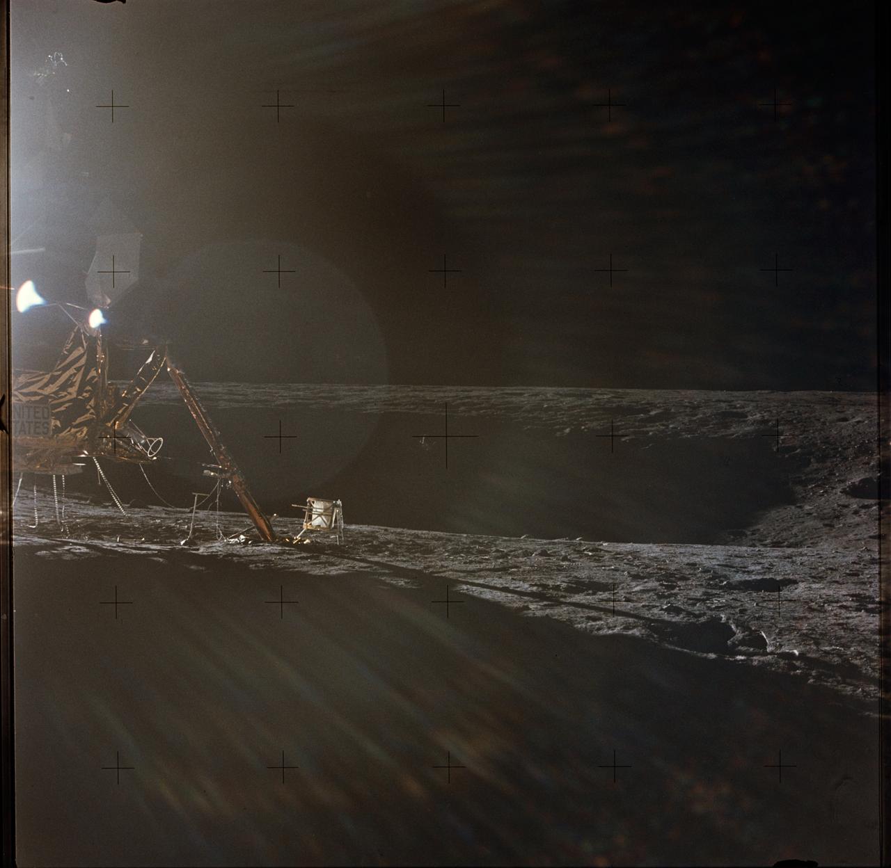
AS12-47-6949 (19-20 Nov. 1969) --- A photograph of the Apollo 12 lunar landing site taken during the extravehicular activity (EVA) of astronauts Charles Conrad Jr., commander; and Alan L. Bean, lunar module pilot. The Apollo 12 Lunar Module (LM) is on the left. Barely visible in the center of the picture, in the shadows on the farside of the crater, is the Surveyor 3 spacecraft. The two spacecraft are about 600 feet apart. Conrad and Bean walked over to Surveyor 3 during their second EVA. The television camera and several other pieces were taken from Surveyor 3 and brought back to Earth for scientific examination. Astronaut Richard F. Gordon Jr., command module pilot, remained with the Command and Service Modules (CSM) in lunar orbit, while astronauts Conrad and Bean descended in the LM to explore the moon. The considerable glare in the picture is caused by the position of the sun. The Apollo tool carrier is the object next to the LM footpad.

AS12-46-6790 (19 Nov. 1969) --- Astronaut Alan L. Bean, lunar module pilot, is photographed at quadrant II of the Lunar Module (LM) during the first Apollo 12 extravehicular activity (EVA) on the moon. This picture was taken by astronaut Charles Conrad Jr., commander. Here, Bean is using a fuel transfer tool to remove the fuel element from the fuel cask mounted on the LM's descent stage. The fuel element was then placed in the Radioisotope Thermoelectric Generator (RTG), the power source for the Apollo Lunar Surface Experiments Package (ALSEP) which was deployed on the moon by the two astronauts. The RTG is next to Bean's right leg. While astronauts Conrad and Bean descended in the LM "Intrepid" to explore the Ocean of Storms region of the moon, astronaut Richard F. Gordon Jr., command module pilot, remained with the Command and Service Modules (CSM) "Yankee Clipper" in lunar orbit.
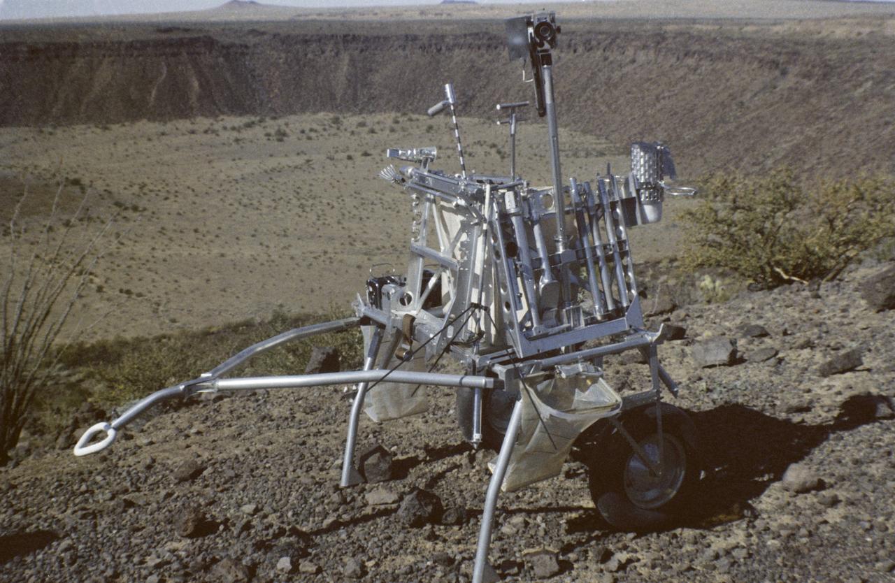
CAPE CANAVERAL, Fla. - Fred W. Haise Jr., Apollo 13 lunar module pilot, participated in a walk-through of the extravehicular activity timeline near the Flight Crew Training Building here today. In the foreground is the lunar surface tool carrier topped by auger-like pipes to be used with a motorized device to obtain soil sample cores in the moon's rugged Fra Mauro region. Apollo 13 is scheduled for launch from Complex 39A no earlier than April 11. The other crew members are James A. Lovell Jr., commander, and Thomas K. Mattingly II, command module pilot. Photo credit: NASA
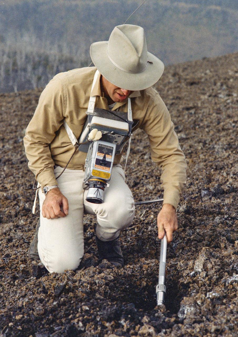
In this photograph, Apollo 11 astronauts Edwin (Buzz) Aldrin (left) and Neil A. Armstrong prepare for the first Lunar landing as they practice gathering rock specimens during a geological field trip to the Quitman Mountains area near the Fort Quitman ruins in far west Texas. They used special lunar geological tools to pick up samples and place them in bags.Their practice paid off in July of the same year. Aboard the Marshall Space Fight center (MSFC) developed Saturn V launch vehicle, the Apollo 11 mission launched from the Kennedy Space Center, Florida on July 16, 1969 and safely returned to Earth on July 24, 1969. The 3-man crew aboard the flight consisted of Armstrong, commander; Aldrin, Lunar Module pilot; and a third astronaut Michael Collins, Command Module pilot. Armstrong was the first human to ever stand on the lunar surface, followed by Aldrin, while Collins remained in lunar orbit. The crew collected 47 pounds of lunar surface material which was returned to Earth for analysis. The lunar surface exploration was concluded in 2½ hours.
In this photograph, Apollo 11 astronaut Neil A. Armstrong uses a geologist’s hammer in selecting rock specimens during a geological field trip to the Quitman Mountains area near the Fort Quitman ruins in far west Texas. Armstrong, alongside astronaut Edwin (Buzz) Aldrin, practiced gathering rock specimens using special lunar geological tools in preparation for the first Lunar landing. Mission was accomplished in July of the same year. Aboard the Marshall Space Fight center (MSFC) developed Saturn V launch vehicle, the Apollo 11 mission launched from The Kennedy Space Center, Florida on July 16, 1969 and safely returned to Earth on July 24, 1969. The 3-man crew aboard the flight consisted of Armstrong, commander; Aldrin, Lunar Module pilot; and a third astronaut Michael Collins, Command Module pilot. Armstrong was the first human to ever stand on the lunar surface, followed by Aldrin, while Collins remained in lunar orbit. The crew collected 47 pounds of lunar surface material which was returned to Earth for analysis. The lunar surface exploration was concluded in 2½ hours.
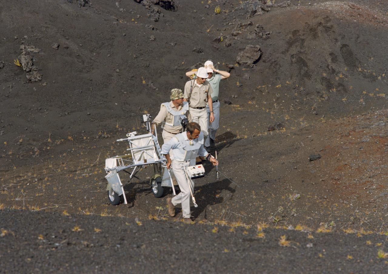
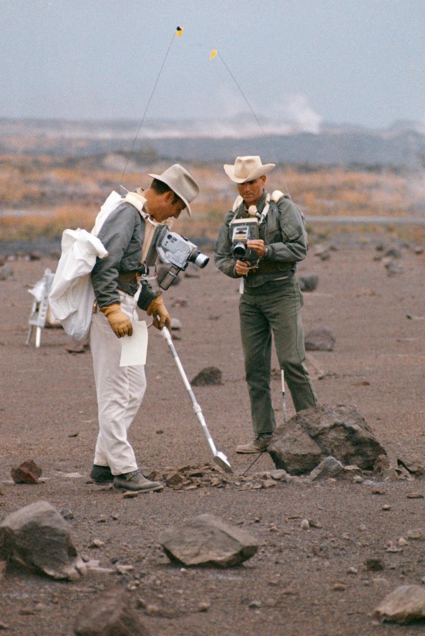
S70-34416 (April 1970) --- At Kapoho, Hawaii, two Apollo 14 prime crew members take part in a simulation of a lunar traverse while two persons from the Manned Spacecraft Center (MSC) observe. The prime and backup crews of the Apollo 14 mission were in Hawaii for several days in April 1970 to visit various sites having features similar to those on the lunar surface. Astronaut Alan B. Shepard Jr. (front), prime crew commander, carries a gnomon (from the Apollo Lunar Hand Tools - ALHT) in his left hand while pulling the Modular Equipment Transporter (MET) with his right hand. He is followed by astronaut Edgar D. Mitchell, prime lunar module pilot, with a Hasselblad lunar surface camera. Michael C. McEwen (second from rear) of the Geology Branch, Lunar and Earth Sciences Division, MSC; and Major William J. Wood of the Lunar Surface Operations Office observe the training activity. Photo credit: NASA
Technicians at NASA’s Michoud Assembly Facility in New Orleans moved the engine section for NASA’s Space Launch System (SLS) rocket to another part of the facility on Sept. 3 to prepare it for joining to the rest of the rocket’s core stage. The engine section, which comprises the lowest portion of the 212-foot-tall stage, is the last major component to be horizontally integrated to the core stage. Michoud crews completed assembly on the flight hardware that will be used for Artemis I, the first lunar mission of SLS and NASA’s Orion spacecraft, on Aug. 29. NASA and Boeing engineers removed the scaffolding surrounding the hardware to use a special tool to properly position the engine section for its attachment to the rest of the stage. The core stage’s two liquid propellant tanks and four RS-25 engines will produce more than 2 million pounds of thrust to send the SLS rocket and Orion on the Artemis lunar missions. The engine section houses the four RS-25 engines and includes vital systems for mounting, controlling and delivering fuel form the propellant tanks to the rocket’s engines. Offering more payload mass, volume capability and energy to speed missions through space, the SLS rocket, along with NASA’s Gateway in lunar orbit and Orion, is part of NASA’s backbone for deep space exploration and the Artemis lunar program. No other rocket is capable of carrying astronauts in Orion around the Moon in a single mission.
Technicians at NASA’s Michoud Assembly Facility in New Orleans moved the engine section for NASA’s Space Launch System (SLS) rocket to another part of the facility on Sept. 3 to prepare it for joining to the rest of the rocket’s core stage. The engine section, which comprises the lowest portion of the 212-foot-tall stage, is the last major component to be horizontally integrated to the core stage. Michoud crews completed assembly on the flight hardware that will be used for Artemis I, the first lunar mission of SLS and NASA’s Orion spacecraft, on Aug. 29. NASA and Boeing engineers removed the scaffolding surrounding the hardware to use a special tool to properly position the engine section for its attachment to the rest of the stage. The core stage’s two liquid propellant tanks and four RS-25 engines will produce more than 2 million pounds of thrust to send the SLS rocket and Orion on the Artemis lunar missions. The engine section houses the four RS-25 engines and includes vital systems for mounting, controlling and delivering fuel form the propellant tanks to the rocket’s engines. Offering more payload mass, volume capability and energy to speed missions through space, the SLS rocket, along with NASA’s Gateway in lunar orbit and Orion, is part of NASA’s backbone for deep space exploration and the Artemis lunar program. No other rocket is capable of carrying astronauts in Orion around the Moon in a single mission.
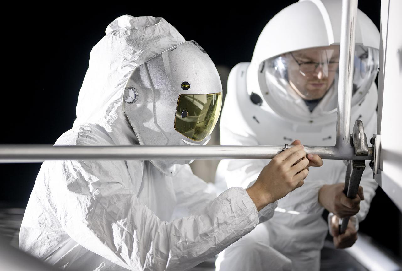
These photos show how teams at NASA’s Marshall Space Flight Center in Huntsville, Alabama, are using the Flat Floor Facility (Building 4619) to understand the lunar lighting environment in preparation for the Artemis III crewed lunar landing mission, slated for 2027. The Flat Floor Facility is an air-bearing floor, providing full-scale simulation capabilities for lunar surface systems by simulating zero gravity in two dimensions. Wearing low-fidelity materials, test engineers can understand how the extreme lighting of the Moon’s South Pole could affect surface operations during Artemis III. High-intensity lights are positioned at a low angle to replicate the strong shadows that are cast across the lunar South Pole by the Sun. Data and analysis from testing at NASA Marshall are improving models Artemis astronauts will use in preparation for lander and surface operations on the Moon during Artemis III. Testing in the facility is also helping cross-agency teams evaluate various tools astronauts may use. NASA Marshall manages the Human Landing System (HLS) Program. For more information, contact NASA Marshall’s Office of Communications at 256-544-0034.
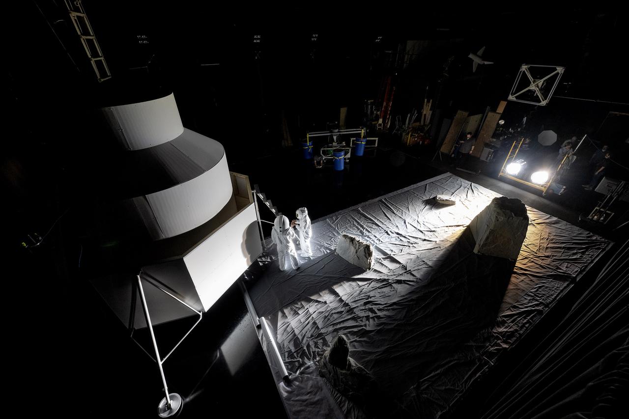
These photos show how teams at NASA’s Marshall Space Flight Center in Huntsville, Alabama, are using the Flat Floor Facility (Building 4619) to understand the lunar lighting environment in preparation for the Artemis III crewed lunar landing mission, slated for 2027. The Flat Floor Facility is an air-bearing floor, providing full-scale simulation capabilities for lunar surface systems by simulating zero gravity in two dimensions. Wearing low-fidelity materials, test engineers can understand how the extreme lighting of the Moon’s South Pole could affect surface operations during Artemis III. High-intensity lights are positioned at a low angle to replicate the strong shadows that are cast across the lunar South Pole by the Sun. Data and analysis from testing at NASA Marshall are improving models Artemis astronauts will use in preparation for lander and surface operations on the Moon during Artemis III. Testing in the facility is also helping cross-agency teams evaluate various tools astronauts may use. NASA Marshall manages the Human Landing System (HLS) Program. For more information, contact NASA Marshall’s Office of Communications at 256-544-0034.
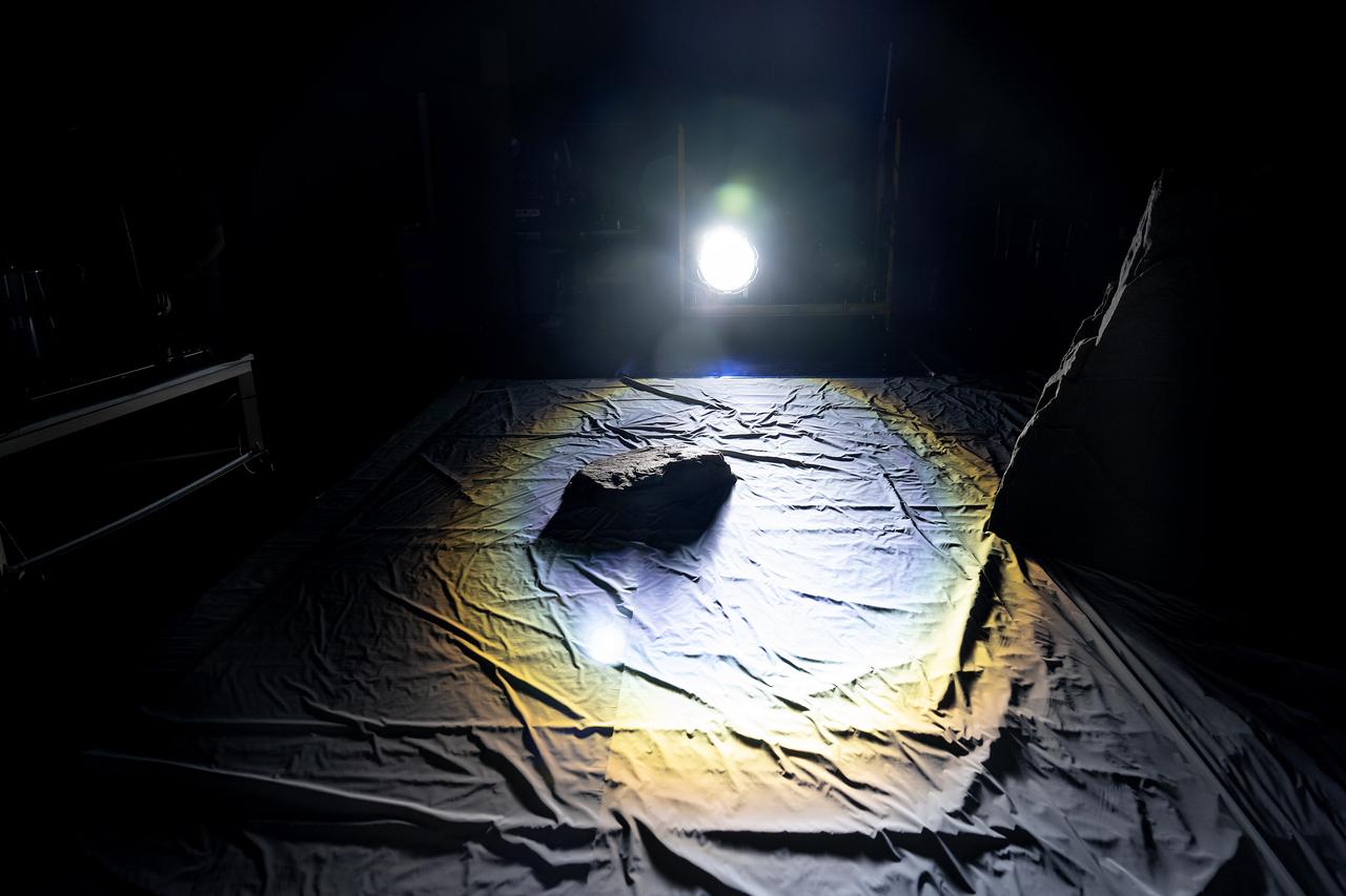
These photos show how teams at NASA’s Marshall Space Flight Center in Huntsville, Alabama, are using the Flat Floor Facility (Building 4619) to understand the lunar lighting environment in preparation for the Artemis III crewed lunar landing mission, slated for 2027. The Flat Floor Facility is an air-bearing floor, providing full-scale simulation capabilities for lunar surface systems by simulating zero gravity in two dimensions. Wearing low-fidelity materials, test engineers can understand how the extreme lighting of the Moon’s South Pole could affect surface operations during Artemis III. High-intensity lights are positioned at a low angle to replicate the strong shadows that are cast across the lunar South Pole by the Sun. Data and analysis from testing at NASA Marshall are improving models Artemis astronauts will use in preparation for lander and surface operations on the Moon during Artemis III. Testing in the facility is also helping cross-agency teams evaluate various tools astronauts may use. NASA Marshall manages the Human Landing System (HLS) Program. For more information, contact NASA Marshall’s Office of Communications at 256-544-0034.