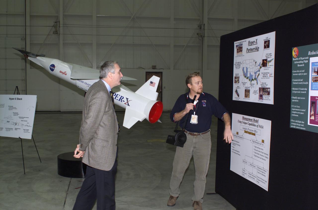
NASA Administrator Sean O'Keefe left, learned about the Mach 10 X-43 research vehicle from manager, Joel Sitz during O'Keefe's visit to the NASA Dryden Flight Research Center, Edwards, California, January 31, 2002.
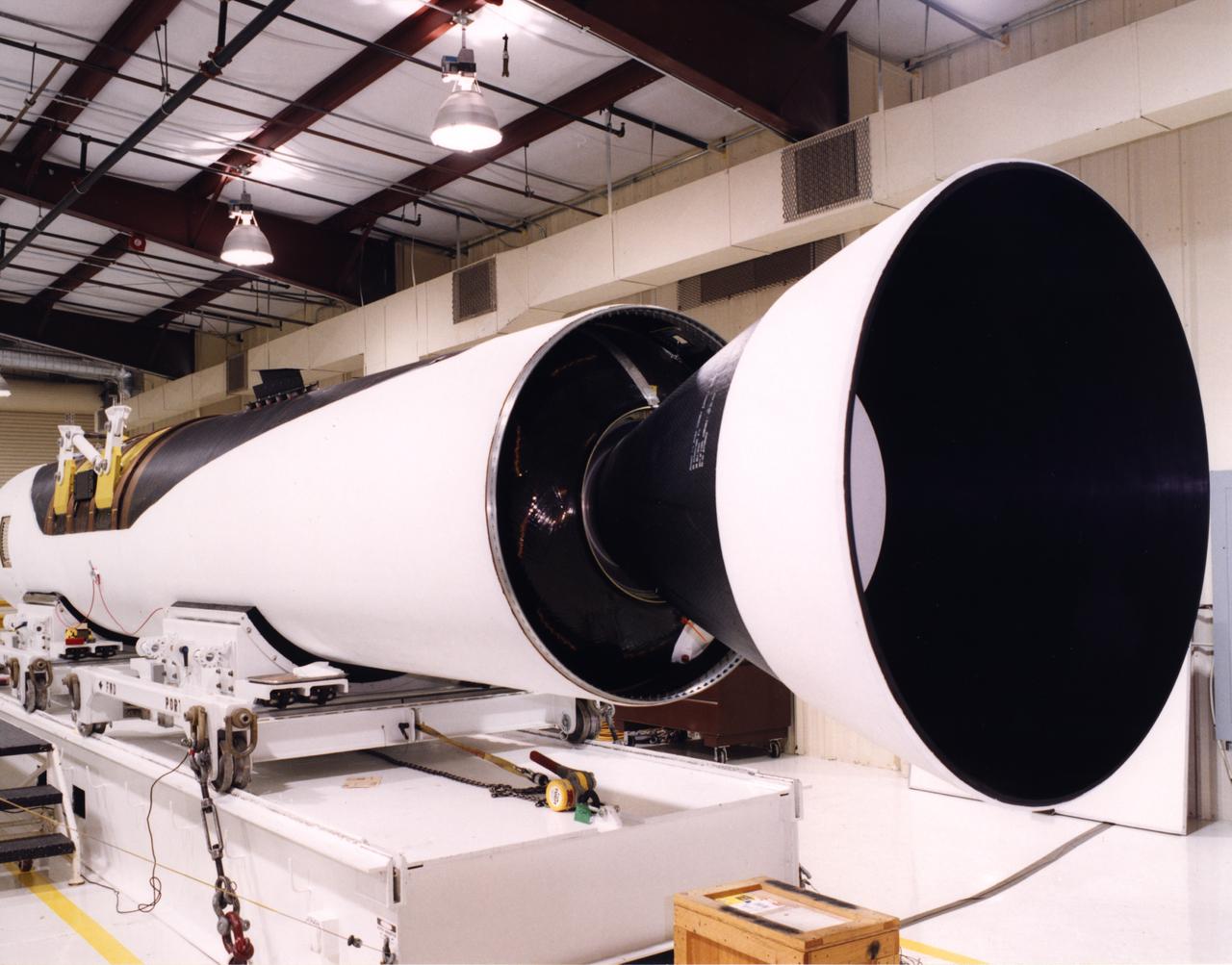
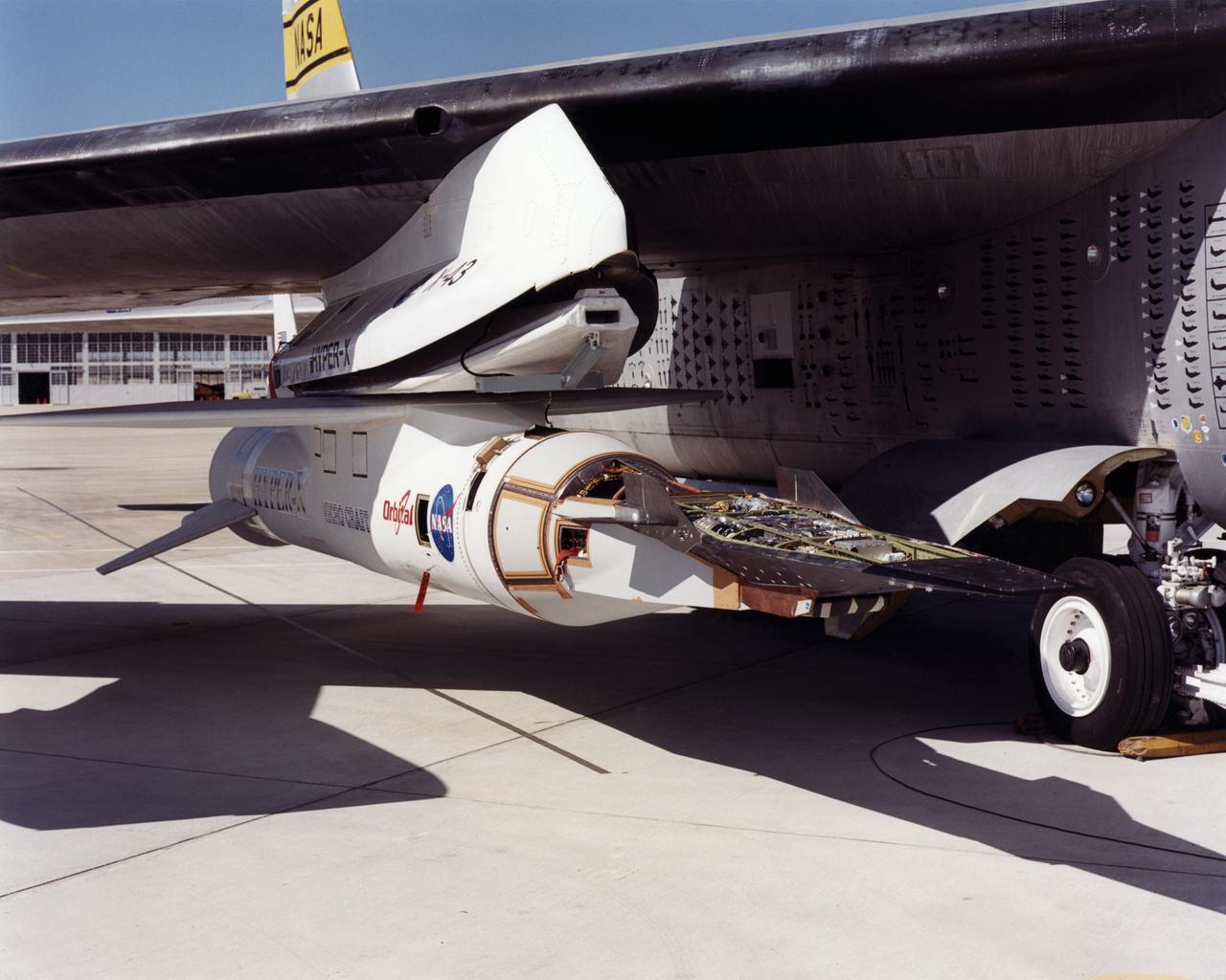
A close-up view of the front end of a Pegasus rocket booster being prepared by technicians at the Dryden Flight Research Center for flight tests with the X-43A "Hypersonic Experimental Vehicle," or "Hyper-X." The X-43A, which will be attached to the Pegasus booster and drop launched from NASA's B-52 mothership, was developed to research dual-mode ramjet/scramjet propulsion system at speeds from Mach 7 up to Mach 10 (7 to 10 times the speed of sound, which varies with temperature and altitude).
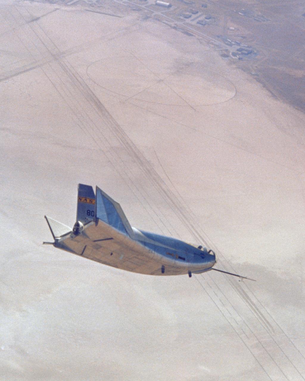
This photo shows the HL-10 in flight, turning to line up with lakebed runway 18. The pilot for this flight, the 29th of the HL-10 series, was Bill Dana. The HL-10 reached a peak altitude of 64,590 feet and a top speed of Mach 1.59 on this particular flight.
Technicians prepare a Pegasus rocket booster for flight tests with the X-43A "Hypersonic Experimental Vehicle," or "Hyper-X." The X-43A, which will be attached to the Pegasus booster and drop launched from NASA's B-52 mothership, was developed to research dual-mode ramjet/scramjet propulsion system at speeds from Mach 7 up to Mach 10 (7 to 10 times the speed of sound, which varies with temperature and altitude).
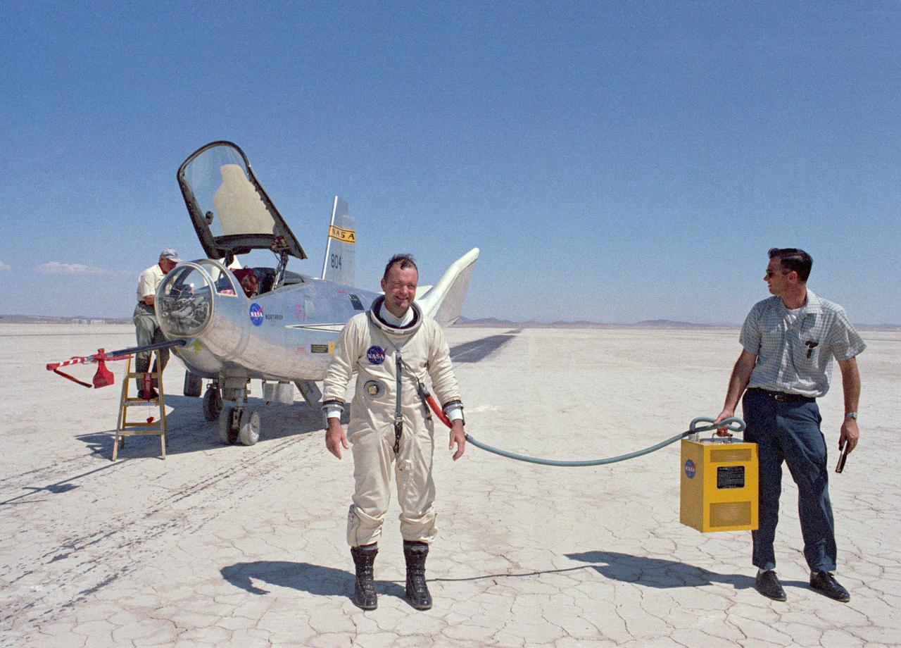
Air Force Major Peter Hoag stands in front of the HL-10 Lifting Body. Maj. Hoag joined the HL-10 program in 1969 and made his first glide flight on June 6, 1969. He made a total of 8 flights in the HL-10. They included the fastest lifting-body flight, which reached Mach 1.861 on Feb. 18, 1970.
A researcher examines a model being installed in the test section of the 10- by 10-Foot Supersonic Wind Tunnel during the 1957 Inspection of the National Advisory Committee for Aeronautics (NACA) Lewis Flight Propulsion Laboratory. The NACA held its annual Inspection at one of its three research laboratories. Representatives from the military, aeronautical industry, universities, and the press were invited to the laboratory to be briefed on the NACA’s latest research efforts and tour the state- of- the- art test facilities. Over 1700 people visited the NACA Lewis in Cleveland, Ohio during the October 7 - 10, 1957 Inspection. NACA researchers Leonard Obery, seen here, James Connors, Leonard, Stitt, David Bowditch gave presentations on high Mach number turbojets at the 10- by 10 tunnel. It had been only 15 years since a jet aircraft had first flown in the US. Since then the sound barrier had been broken and speeds of Mach 2.5 had been achieved. In the late 1950s NACA researchers sought to create an engine that could achieve Mach 4. This type of engine would require an extremely long inlet and nozzle which would have to be capable of adjusting their diameter for different speeds. A Mach 4 engine would require new composite materials to withstand the severe conditions, modified airframes to hold the longer engines, and high temperature seals and lubricants. The 10- by 10-foot tunnel, which had only been in operation for a year and a half, would play a critical role in these studies. NACA researchers at other facilities discussed high energy aircraft fuels and rocket propellants, aircraft noise reduction, hypersonic flight, nuclear propulsion, and high temperature materials.
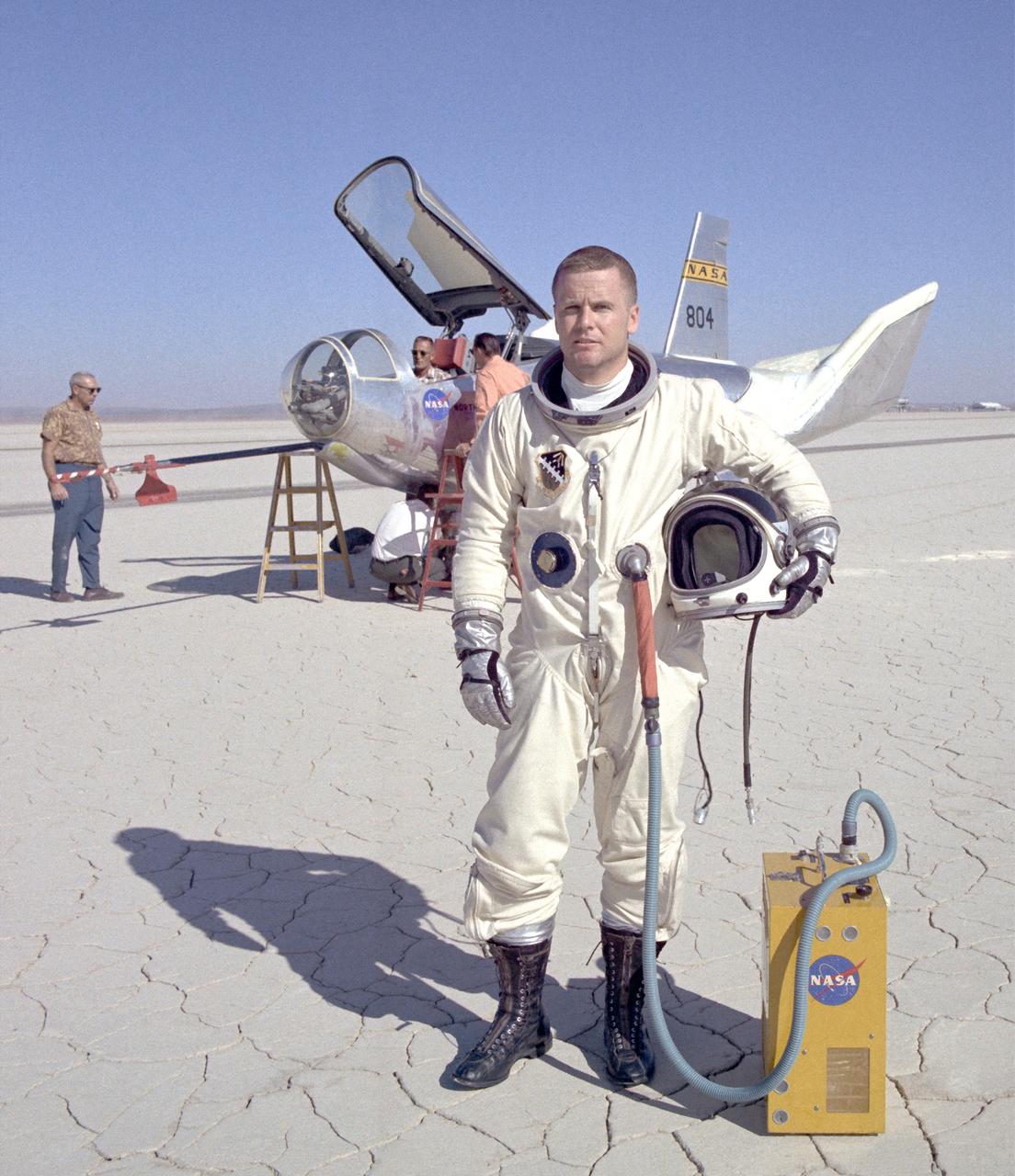
NASA research pilot Bill Dana after his fourth free flight (1 glide and 3 powered) in the HL-10. This particular flight reached a maximum speed of Mach 1.45. Dana made a total of nine HL-10 flights (1 glide and 8 powered), and his lifting body experience as a whole included several car tow and 1 air tow flights in the M2-F1; 4 glide and 15 powered flights in the M2-F3; and 2 powered flights in the X-24B. He is wearing a pressure suit for protection against the cockpit depressurizing at high altitudes. The air conditioner box held by the ground crewman provides cool air to prevent overheating.
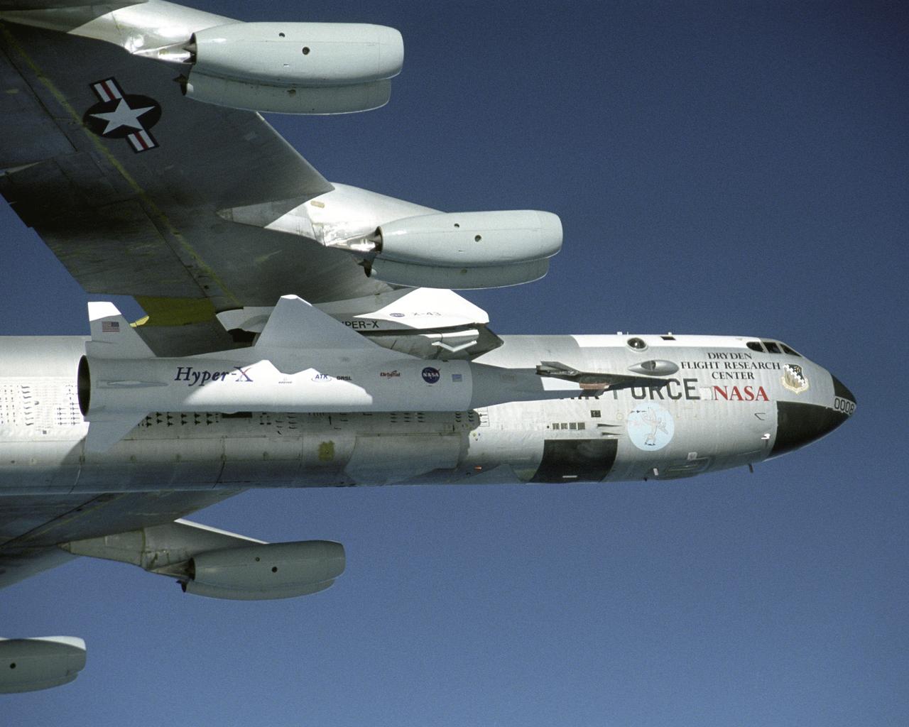
The X-43A hypersonic research aircraft and its modified Pegasus® booster rocket are nestled under the wing of NASA's NB-52B carrier aircraft during pre-flight systems testing at the Dryden Flight Research Center, Edwards, Calif. The combined systems test was one of the last major milestones in the Hyper-X research program before the first X-43A flight. The X-43A flights will be the first actual flight tests of an aircraft powered by a revolutionary supersonic-combustion ramjet ("scramjet") engine capable of operating at hypersonic speeds (above Mach 5, or five times the speed of sound). The 12-foot, unpiloted research vehicle was developed and built by MicroCraft Inc., Tullahoma, Tenn., under NASA contract. The booster was built by Orbital Sciences Corp., Dulles, Va. After being air-launched from NASA's venerable NB-52 mothership, the booster will accelerate the X-43A to test speed and altitude. The X-43A will then separate from the rocket and fly a pre-programmed trajectory, conducting aerodynamic and propulsion experiments until it descends into the Pacific Ocean. Three research flights are planned, two at Mach 7 and one at Mach 10.
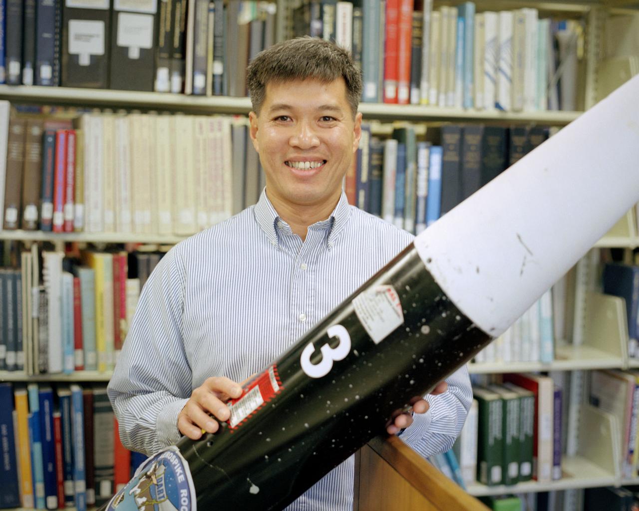
Trong Bui, NASA Dryden's principal investigator for the aerospike rocket tests, holds the first of two 10-ft. long rockets that were flown at speeds up to Mach 1.5, the first known supersonic tests of rockets with aerospike nozzles. The goals of the flight research project were to obtain aerospike rocket nozzle performance data in flight and to investigate the effects of transonic flow and transient flight conditions on aerospike nozzle performance.
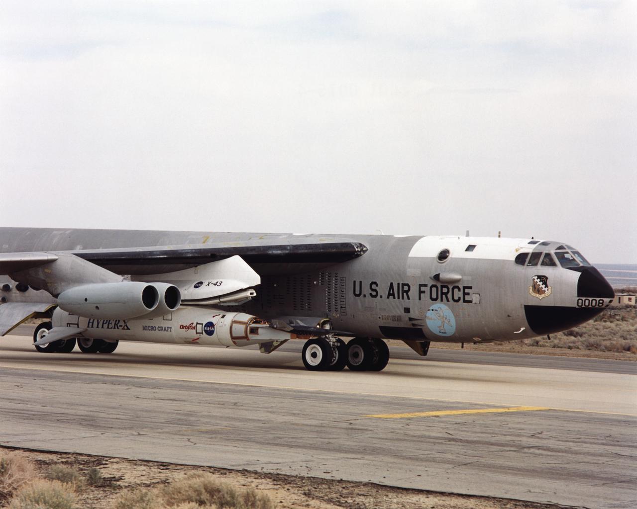
As part of a combined systems test conducted by NASA Dryden Flight Research Center, NASA's NB-52B carrier aircraft rolls down a taxiway at Edwards Air Force Base with the X-43A hypersonic research aircraft and its modified Pegasus® booster rocket attached to a pylon under its right wing. The taxi test was one of the last major milestones in the Hyper-X research program before the first X-43A flight. The X-43A flights will be the first actual flight tests of an aircraft powered by a revolutionary supersonic-combustion ramjet ("scramjet") engine capable of operating at hypersonic speeds (above Mach 5, or five times the speed of sound). The 12-foot, unpiloted research vehicle was developed and built by MicroCraft Inc., Tullahoma, Tenn., under NASA contract. The booster was built by Orbital Sciences Corp., Dulles, Va. After being air-launched from NASA's venerable NB-52 mothership, the booster will accelerate the X-43A to test speed and altitude. The X-43A will then separate from the rocket and fly a pre-programmed trajectory, conducting aerodynamic and propulsion experiments until it descends into the Pacific Ocean. Three research flights are planned, two at Mach 7 and one at Mach 10.
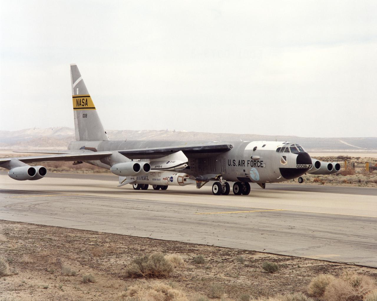
NASA's NB-52B carrier aircraft rolls down a taxiway at Edwards Air Force Base with the X-43A hypersonic research aircraft and its modified Pegasus® booster rocket slung from a pylon under its right wing. Part of a combined systems test conducted by NASA's Dryden Flight Research Center at Edwards, the taxi test was one of the last major milestones in the Hyper-X research program before the first X-43A flight. The X-43A flights will be the first actual flight tests of an aircraft powered by a revolutionary supersonic-combustion ramjet ("scramjet") engine capable of operating at hypersonic speeds (above Mach 5, or five times the speed of sound). The 12-foot, unpiloted research vehicle was developed and built by MicroCraft Inc., Tullahoma, Tenn., under NASA contract. The booster was built by Orbital Sciences Corp., Dulles, Va.,After being air-launched from NASA's venerable NB-52 mothership, the booster will accelerate the X-43A to test speed and altitude. The X-43A will then separate from the rocket and fly a pre-programmed trajectory, conducting aerodynamic and propulsion experiments until it descends into the Pacific Ocean. Three research flights are planned, two at Mach 7 and one at Mach 10, with the first tentatively scheduled for late spring to early summer, 2001.

The first of three X-43A hypersonic research aircraft and its modified Pegasus® booster rocket recently underwent combined systems testing while mounted to NASA's NB-52B carrier aircraft at the Dryden Flight Research Center, Edwards, Calif. The combined systems test was one of the last major milestones in the Hyper-X research program before the first X-43A flight. The X-43A flights will be the first actual flight tests of an aircraft powered by a revolutionary supersonic-combustion ramjet ("scramjet") engine capable of operating at hypersonic speeds (above Mach 5, or five times the speed of sound). The 12-foot, unpiloted research vehicle was developed and built by MicroCraft Inc., Tullahoma, Tenn., under NASA contract. The booster was built by Orbital Sciences Corp., Dulles, Va.,After being air-launched from NASA's venerable NB-52 mothership, the booster will accelerate the X-43A to test speed and altitude. The X-43A will then separate from the rocket and fly a pre-programmed trajectory, conducting aerodynamic and propulsion experiments until it descends into the Pacific Ocean. Three research flights are planned, two at Mach 7 and one at Mach 10.
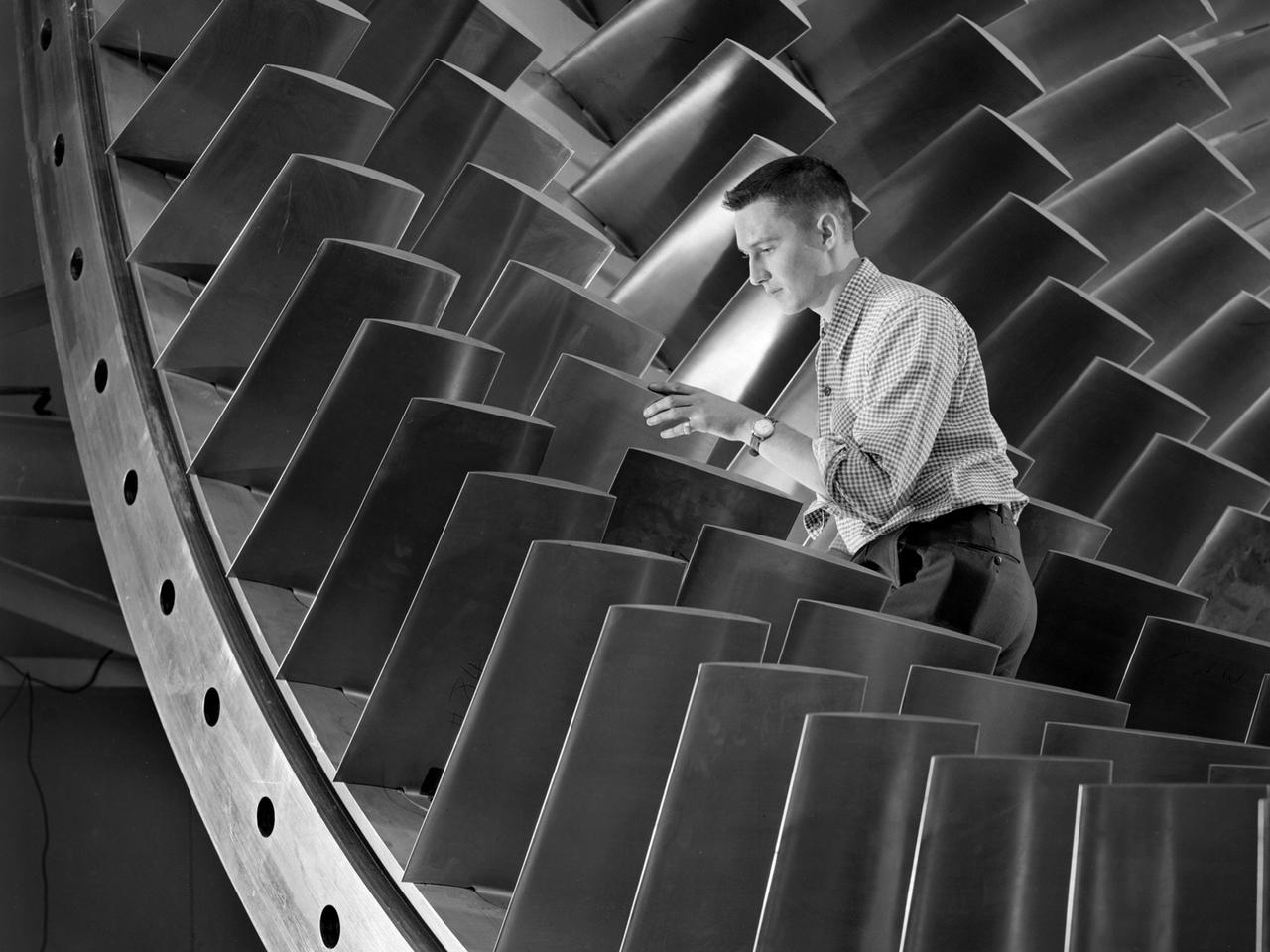
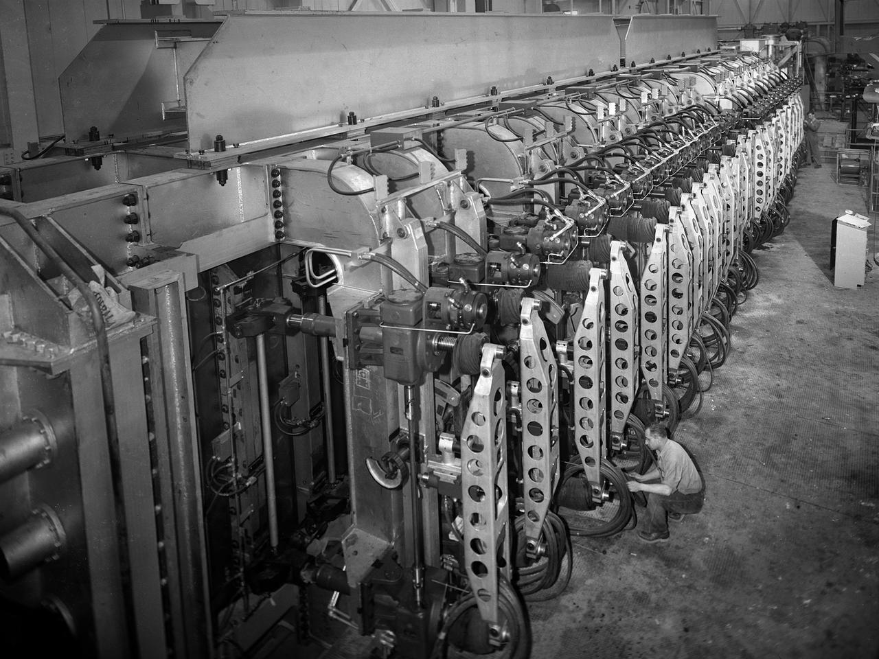
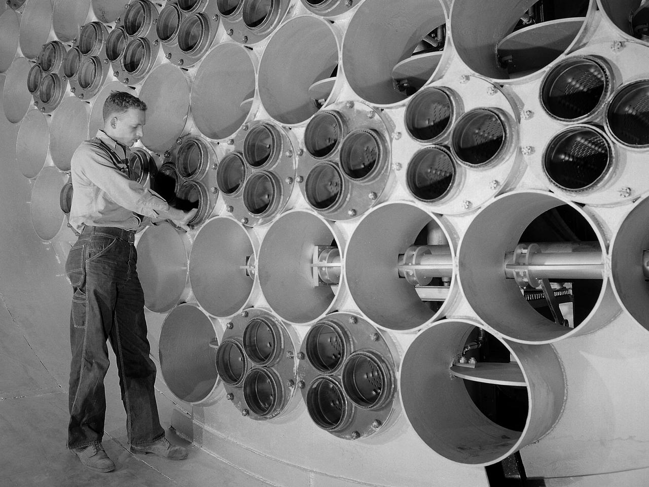
An engineer examines the main compressor for the 10- by 10-Foot Supersonic Wind Tunnel at the National Advisory Committee for Aeronautics (NACA) Lewis Flight Propulsion Laboratory. The engineers were preparing the new wind tunnel for its initial runs in early 1956. The 10- by 10 was the most powerful propulsion wind tunnel in the nation. The facility was part of Congress’ Unitary Plan Act which coordinated wind tunnel construction at the NACA, Air Force, industry, and universities. The 10- by 10 was the largest of the three NACA tunnels built under the act. The 20-foot diameter eight-stage axial flow compressor, seen in this photograph, could generate air flows up to Mach 2.5 through the test section. The stainless steel compressor had 584 blades ranging from 1.8 to 3.25 feet in length. This main compressor was complemented by a secondary axial flow compressor. Working in tandem the two could generate wind streams up to Mach 3.5. The Cleveland Chamber of Commerce presented NACA Lewis photographer Bill Bowles with a second place award for this photograph in their Business and Professional category. The photograph was published in October 1955 edition of its periodical, The Clevelander, which highlighted local professional photographers. Fellow Lewis photographer Gene Giczy won second place in another category for a photograph of Cleveland Municipal Airport.
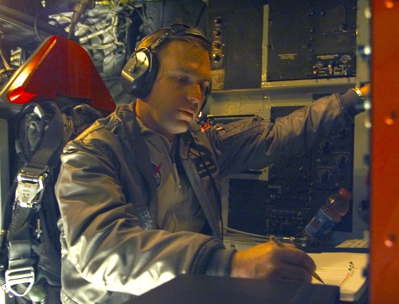
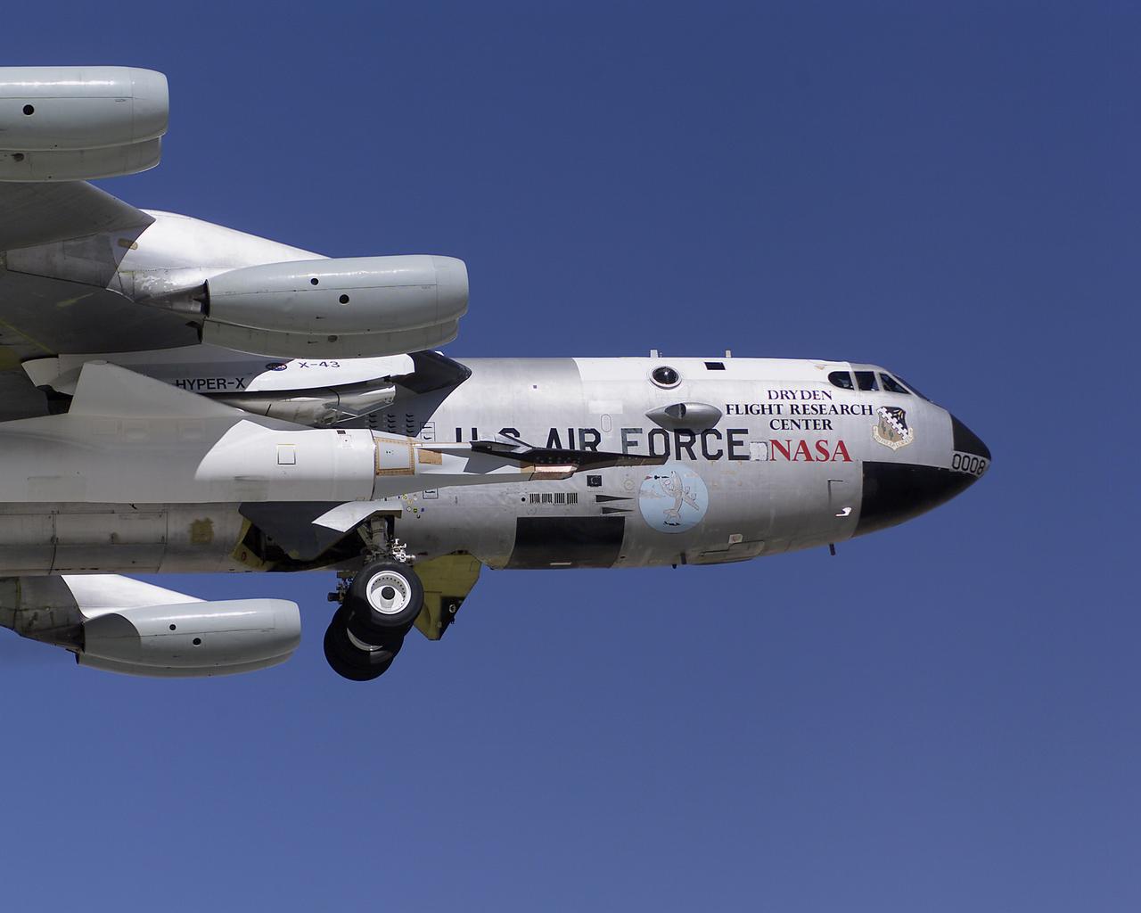
NASA X-43A Monitor Station Operator Brad Neal performs final checks and pre-flight preparations aboard the B-52 for the third X-43A research vehicle Mach 10 flight on November 16, 2004. Takeoff of the B-52B mothership carrying the X-43A took place at 1 p.m., PST, with launch of the booster rocket/X-43A approximately an hour later.
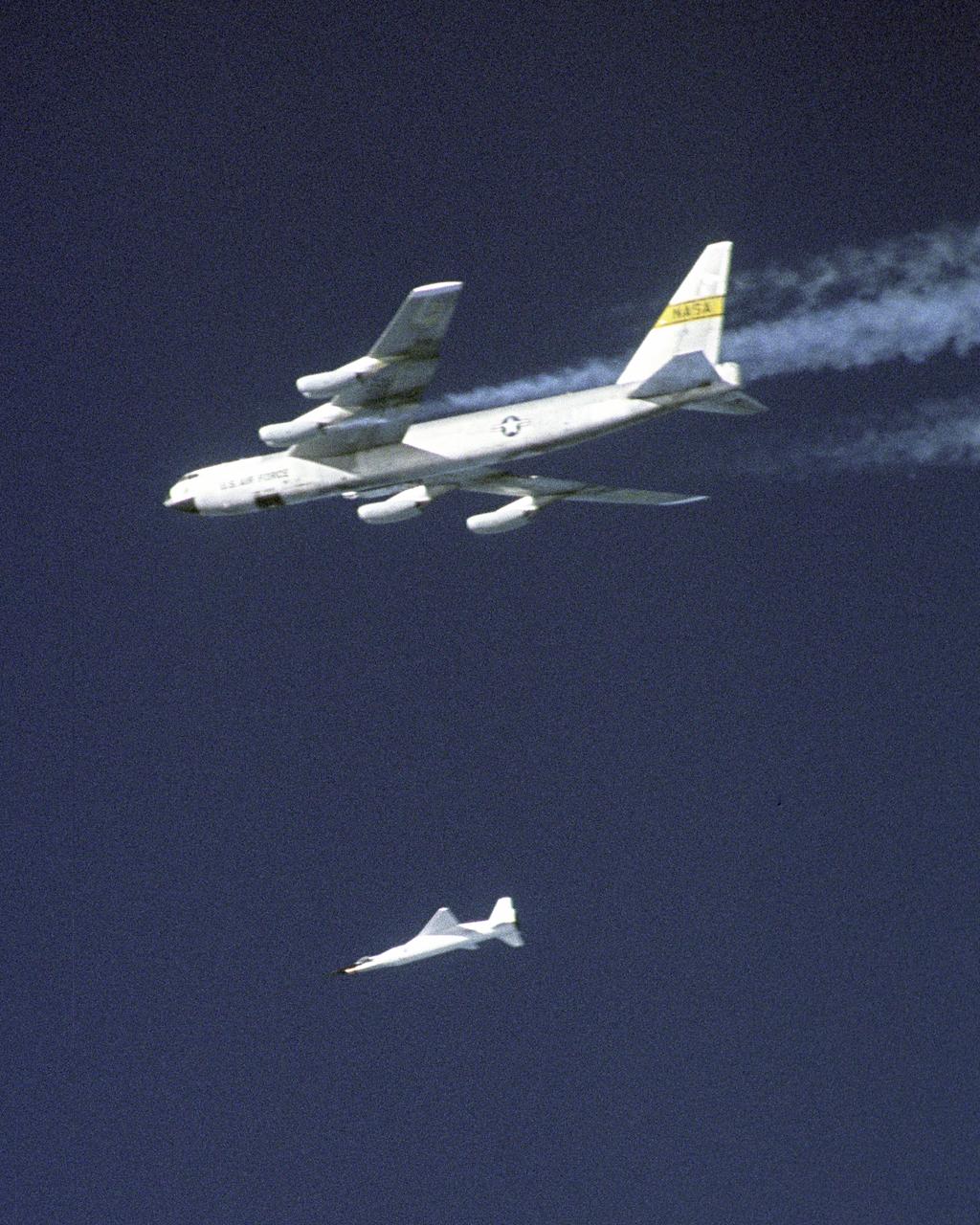
The third X-43A hypersonic research aircraft and its modified Pegasus booster rocket drop away from NASA's B-52B launch aircraft over the Pacific Ocean on November 16, 2004. The mission originated from the NASA Dryden Flight Research Center at Edwards Air Force Base, California. Moments later the Pegasus booster ignited to accelerate the X-43A to its intended speed of Mach 10.
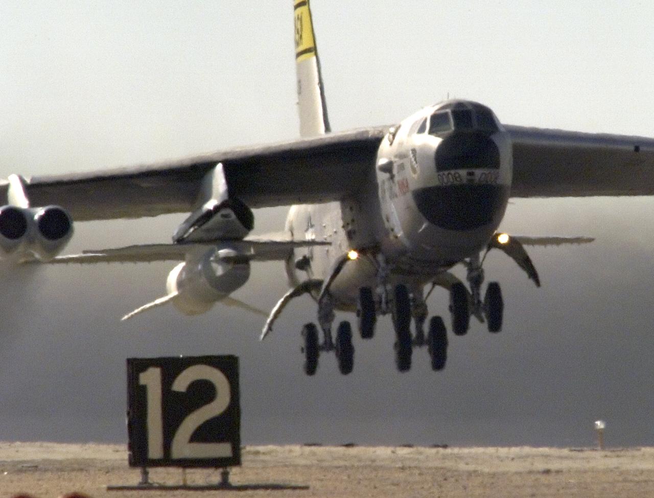
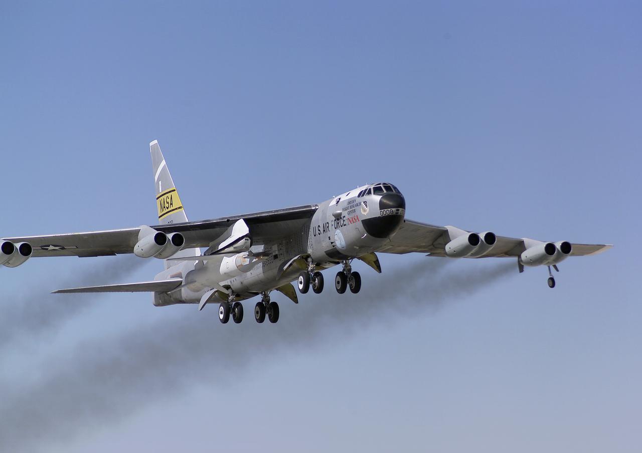
The third X-43A hypersonic research aircraft and its modified Pegasus booster rocket left the runway, carried aloft by NASA's B-52B launch aircraft from the NASA Dryden Flight Research Center at Edwards Air Force Base, California, on November 16, 2004. About an hour later the Pegasus booster was launched from the B-52 to accelerate the X-43A to its intended speed of Mach 10.
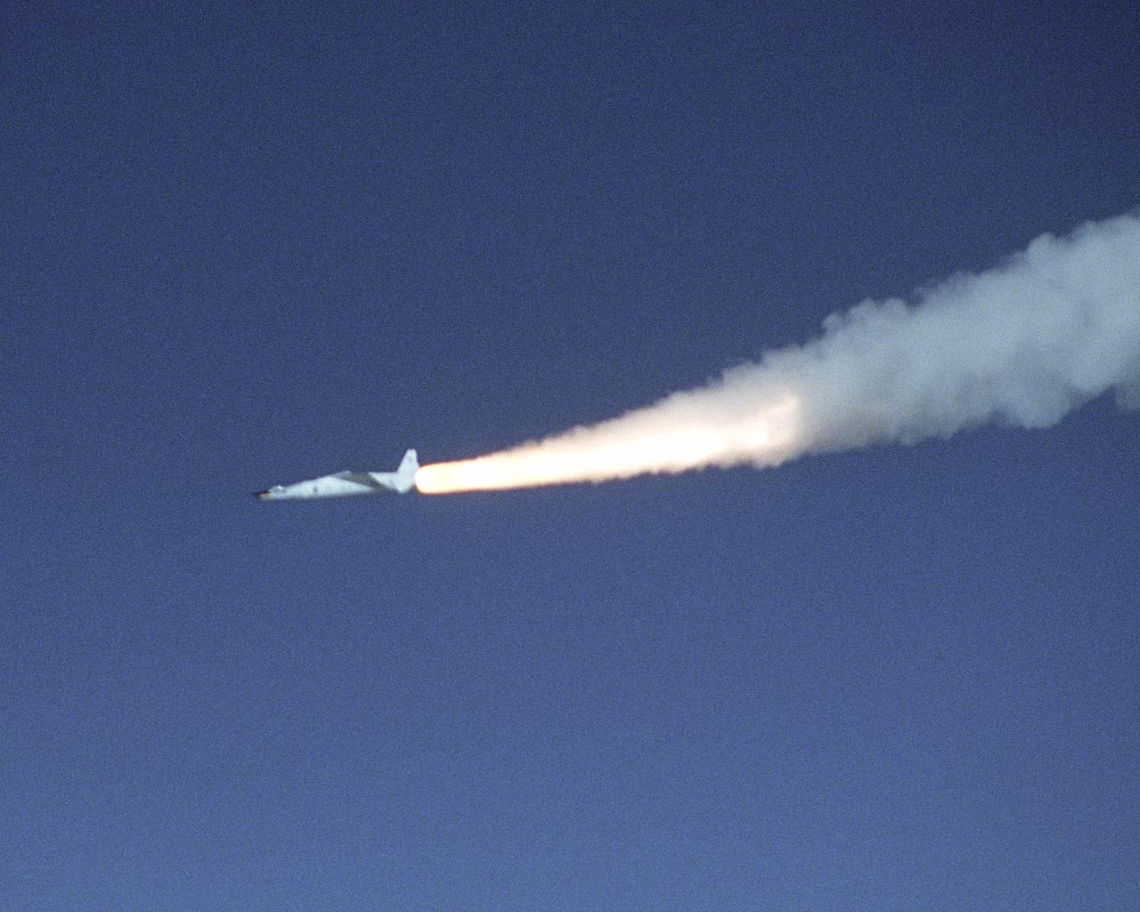
The third X-43A hypersonic research aircraft and its modified Pegasus booster rocket accelerate after launch from NASA's B-52B launch aircraft over the Pacific Ocean on November 16, 2004. The mission originated from the NASA Dryden Flight Research Center at Edwards Air Force Base, California. Minutes later the X-43A separated from the Pegasus booster and accelerated to its intended speed of Mach 10.
The third X-43A hypersonic research aircraft, attached to a modified Pegasus booster rocket, was taken to launch altitude by NASA's B-52B launch aircraft from the NASA Dryden Flight Research Center at Edwards Air Force Base, California, on November 16, 2004. About an hour later the Pegasus booster was released from the B-52 to accelerate the X-43A to its intended speed of Mach 10.
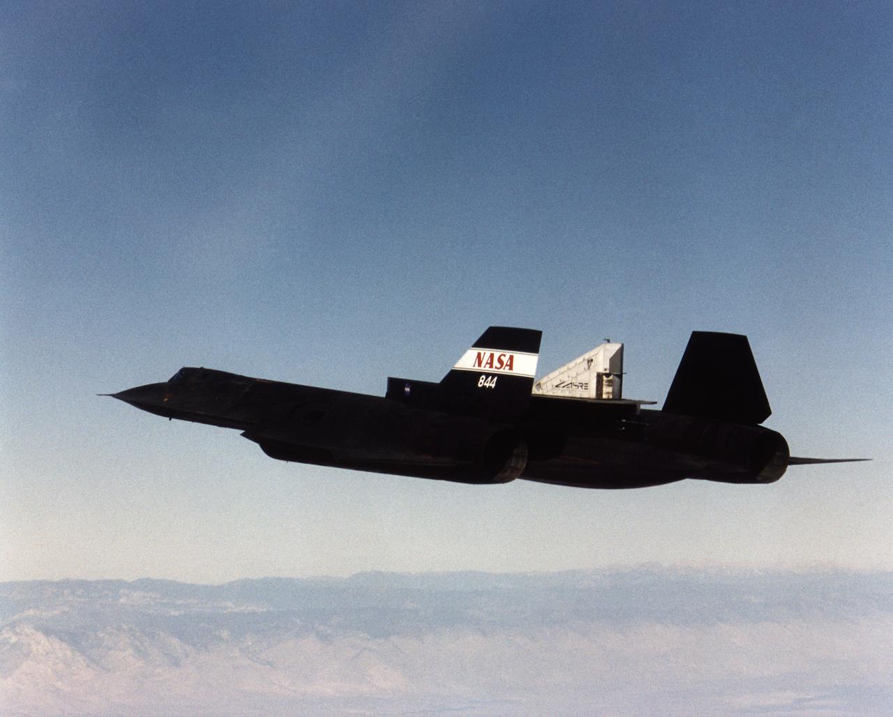
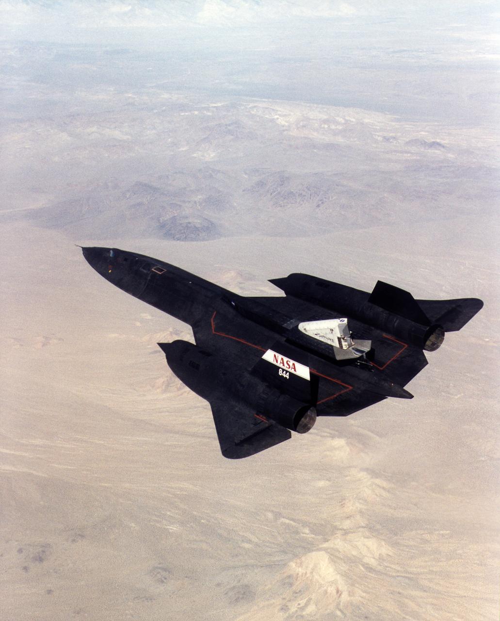
A NASA SR-71 successfully completed its first flight 31 October 1997 as part of the NASA/Rocketdyne/Lockheed Martin Linear Aerospike SR-71 Experiment (LASRE) at NASA's Dryden Flight Research Center, Edwards, California. The SR-71 took off at 8:31 a.m. PST. The aircraft flew for one hour and fifty minutes, reaching a maximum speed of Mach 1.2 before landing at Edwards at 10:21 a.m. PST, successfully validating the SR-71/linear aerospike experiment configuration. The goal of the first flight was to evaluate the aerodynamic characteristics and the handling of the SR-71/linear aerospike experiment configuration. The engine was not fired during the flight.
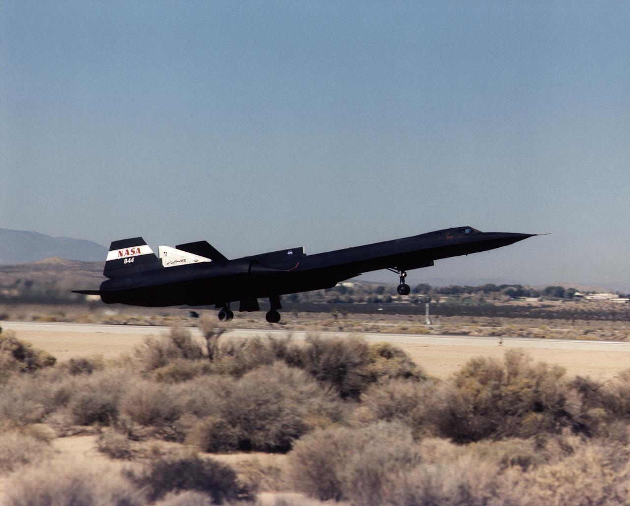
A NASA SR-71 takes off Oct. 31, making its first flight as part of the NASA/Rocketdyne/Lockheed Martin Linear Aerospike SR-71 Experiment (LASRE) at NASA's Dryden Flight Research Center, Edwards, California. The SR-71 took off at 8:31 a.m. PST. The aircraft flew for one hour and fifty minutes, reaching a maximum speed of Mach 1.2 before landing at Edwards at 10:21 a.m. PST, successfully validating the SR-71/linear aerospike experiment configuration. The goal of the first flight was to evaluate the aerodynamic characteristics and the handling of the SR-71/linear aerospike experiment configuration. The engine was not fired during the flight.
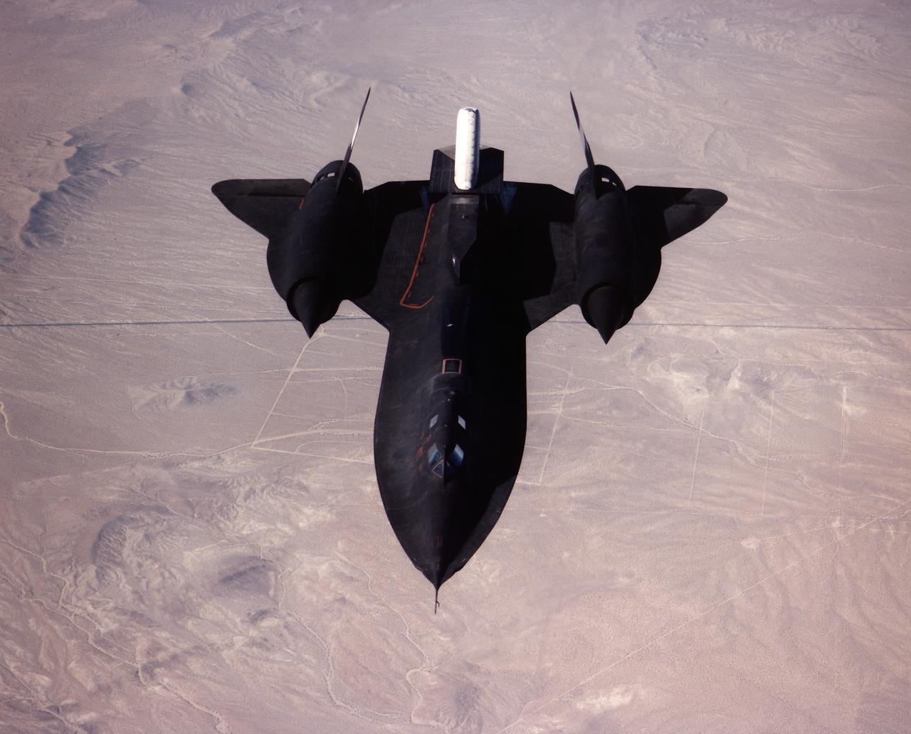
A NASA SR-71 made its successful first flight Oct. 31 as part of the NASA/Rocketdyne/Lockheed Martin Linear Aerospike SR-71 Experiment (LASRE) at NASA's Dryden Flight Research Center, Edwards, California. The SR-71 took off at 8:31 a.m. PST. The aircraft flew for one hour and fifty minutes, reaching a maximum speed of Mach 1.2 before landing at Edwards at 10:21 a.m. PST, successfully validating the SR-71/linear aerospike experiment configuration. The goal of the first flight was to evaluate the aerodynamic characteristics and the handling of the SR-71/linear aerospike experiment configuration. The engine was not fired during the flight.
A NASA SR-71 successfully completed its first flight 31 October 1997 as part of the NASA/Rocketdyne/Lockheed Martin Linear Aerospike SR-71 Experiment (LASRE) at NASA's Dryden Flight Research Center, Edwards, California. The SR-71 took off at 8:31 a.m. PST. The aircraft flew for one hour and fifty minutes, reaching a maximum speed of Mach 1.2 before landing at Edwards at 10:21 a.m. PST, successfully validating the SR-71/linear aerospike experiment configuration. The goal of the first flight was to evaluate the aerodynamic characteristics and the handling of the SR-71/linear aerospike experiment configuration. The engine was not fired during the flight.
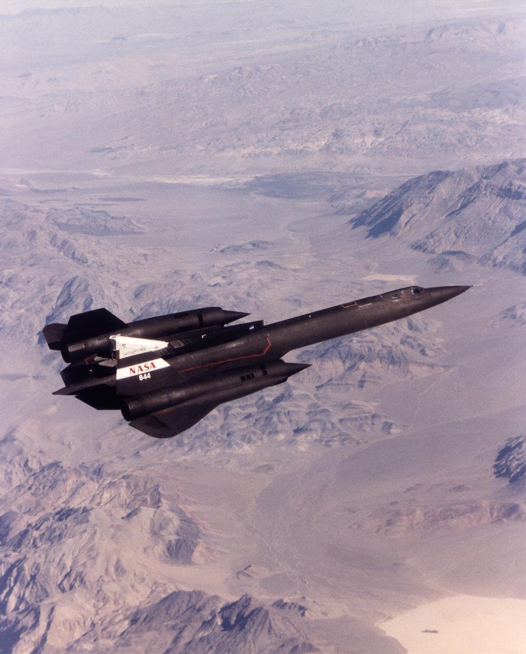
A NASA SR-71 made its successful first flight Oct. 31 as part of the NASA/Rocketdyne/ Lockheed Martin Linear Aerospike SR-71 Experiment (LASRE) at NASA's Dryden Flight Research Center, Edwards, California. The SR-71 took off at 8:31 a.m. PST. The aircraft flew for one hour and fifty minutes, reaching a maximum speed of Mach 1.2 before landing at Edwards at 10:21 a.m. PST, successfully validating the SR-71/linear aerospike experiment configuration. The goal of the first flight was to evaluate the aerodynamic characteristics and the handling of the SR-71/linear aerospike experiment configuration. The engine was not fired during the flight.
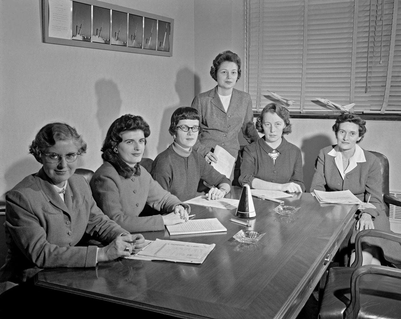
Women Scientists: Lucille Coltrane, Jean Clark Keating, Katherine Cullie Speegle, Doris 'Dot' Lee, Ruth Whitman, and Emily Stephens Mueller,Lucille Coltrane is at the far left. She was a computer and worked for Norm Crabill who provided positive identification. Lucille authored a NACA Research Memorandum, Investigation of Two Bluff Shapes in Axial Free Flight Over a Mach Number Range From 0.35 to 2.15 in 1958. Next to Lucille is Jean Clark Keating. Jean was identified by Mary Woerner who said that both Jean and her husband Jerry are now deceased. The third woman from the left is Katherine Cullie Speegle. Katherine co-authored two research papers: Preliminary Results From a Free-Flight Investigation of Boundary-Layer Transition and Heat Transfer on a Highly Polished 8-Inch-Diameter Hemisphere-Cylinder at Mach Numbers up to 3 and Reynolds Numbers Based on a Length of 1 Foot up to 17.7 x 10 to the 6th and Heat Transfer For Mach Numbers Up to 2.2 and Pressure Distributions for Mach Numbers Up to 4.7 From Flight Investigations of a Flat-Face Cone and a Hemisphere-Cone. Norm remembered the woman standing as Doris. Mary Alice identified her as Doris 'Dot' Lee, who worked with Katherine Speegle. Dot was married to a NASA engineer named John Lee. Next to Doris is Ruth Whitman. Norm remembered she and her husband owned a Howard DGA 15 at the airport in WEst Point. That prompted Mary Alice to remember her name and that her husband was Jim. The woman seated on the right is Emily Stephens Mueller. Norm remembers that Emily went to Houston as part of the Space Task Group, but retired back here on the peninsula. In 2008, Emily attended the NACA Reunion X11. She walked over to a table of books about the history of NACA, former NACA facilities and the organization's aviation pioneers and saw a book about women of flight from the Dryden Research Center and paused, then pointed somewhat in amazement. "That’s me," she said of a picture on the cover of her on the far left of a li
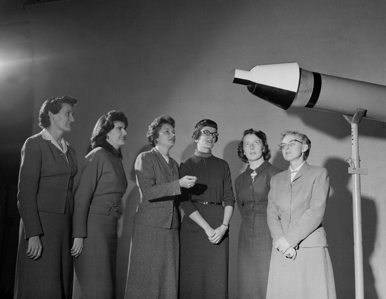
Women Scientists: Lucille Coltrane, Jean Clark Keating, Katherine Cullie Speegle, Doris 'Dot' Lee, Ruth Whitman, and Emily Stephens Mueller,Lucille Coltrane is at the far left. She was a computer and worked for Norm Crabill who provided positive identification. Lucille authored a NACA Research Memorandum, Investigation of Two Bluff Shapes in Axial Free Flight Over a Mach Number Range From 0.35 to 2.15 in 1958. Next to Lucille is Jean Clark Keating. Jean was identified by Mary Woerner who said that both Jean and her husband Jerry are now deceased. The third woman from the left is Katherine Cullie Speegle. Katherine co-authored two research papers: Preliminary Results From a Free-Flight Investigation of Boundary-Layer Transition and Heat Transfer on a Highly Polished 8-Inch-Diameter Hemisphere-Cylinder at Mach Numbers up to 3 and Reynolds Numbers Based on a Length of 1 Foot up to 17.7 x 10 to the 6th and Heat Transfer For Mach Numbers Up to 2.2 and Pressure Distributions for Mach Numbers Up to 4.7 From Flight Investigations of a Flat-Face Cone and a Hemisphere-Cone. Norm remembered the woman standing as Doris. Mary Alice identified her as Doris 'Dot' Lee, who worked with Katherine Speegle. Dot was married to a NASA engineer named John Lee. Next to Doris is Ruth Whitman. Norm remembered she and her husband owned a Howard DGA 15 at the airport in WEst Point. That prompted Mary Alice to remember her name and that her husband was Jim. The woman seated on the right is Emily Stephens Mueller. Norm remembers that Emily went to Houston as part of the Space Task Group, but retired back here on the peninsula. In 2008, Emily attended the NACA Reunion X11. She walked over to a table of books about the history of NACA, former NACA facilities and the organization's aviation pioneers and saw a book about women of flight from the Dryden Research Center and paused, then pointed somewhat in amazement. "That’s me," she said of a picture on the cover of her on the far left of a li
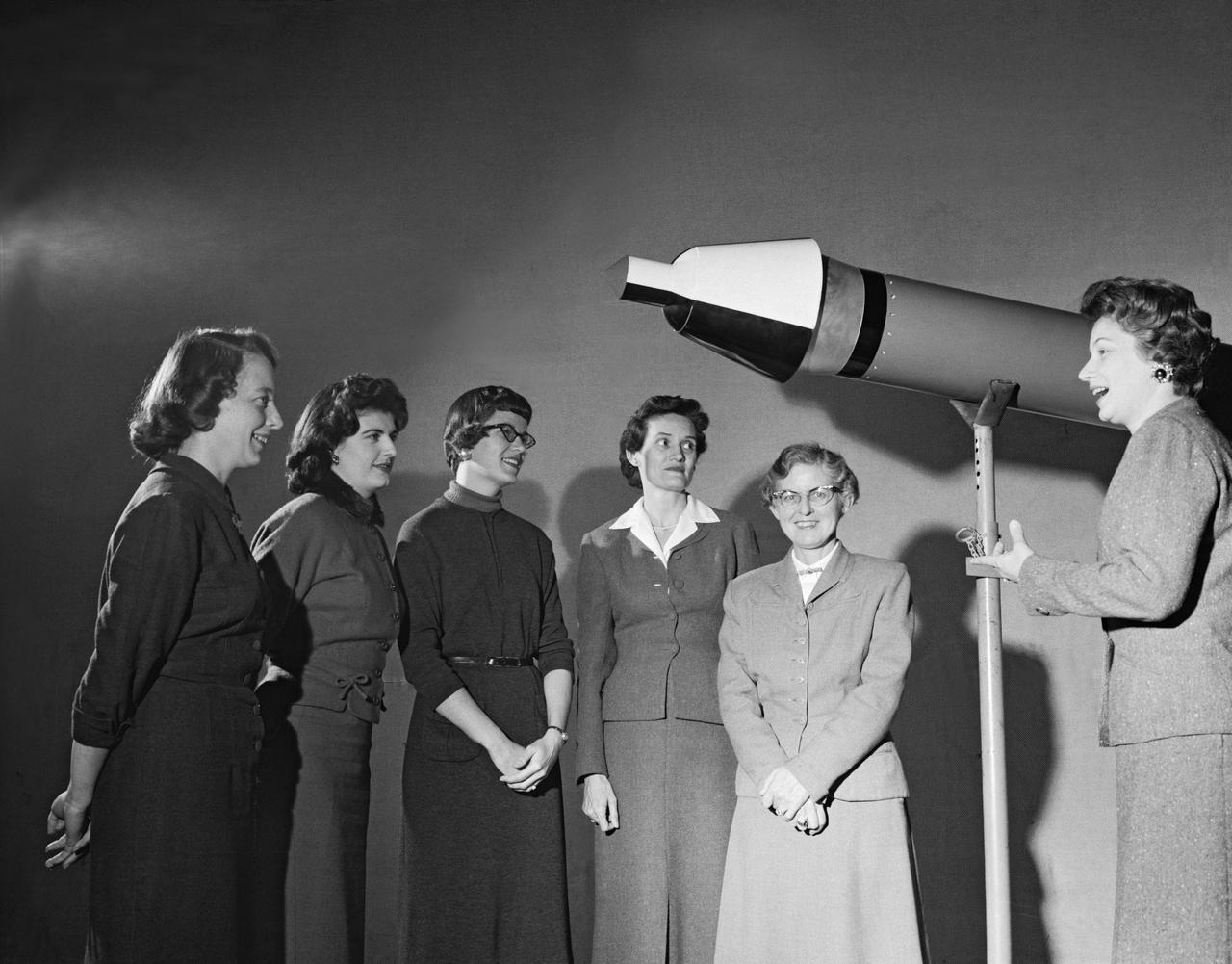
Women Scientists: Lucille Coltrane, Jean Clark Keating, Katherine Cullie Speegle, Doris "Dot" Lee, Ruth Whitman, and Emily Stephens Mueller,Lucille Coltrane is at the far left. She was a computer and worked for Norm Crabill who provided positive identification. Lucille authored a NACA Research Memorandum, Investigation of Two Bluff Shapes in Axial Free Flight Over a Mach Number Range From 0.35 to 2.15 in 1958. Next to Lucille is Jean Clark Keating. Jean was identified by Mary Woerner who said that both Jean and her husband Jerry are now deceased. The third woman from the left is Katherine Cullie Speegle. Katherine co-authored two research papers: Preliminary Results From a Free-Flight Investigation of Boundary-Layer Transition and Heat Transfer on a Highly Polished 8-Inch-Diameter Hemisphere-Cylinder at Mach Numbers up to 3 and Reynolds Numbers Based on a Length of 1 Foot up to 17.7 x 10 to the 6th and Heat Transfer For Mach Numbers Up to 2.2 and Pressure Distributions for Mach Numbers Up to 4.7 From Flight Investigations of a Flat-Face Cone and a Hemisphere-Cone. Norm remembered the woman standing as Doris. Mary Alice identified her as Doris 'Dot' Lee, who worked with Katherine Speegle. Dot was married to a NASA engineer named John Lee. Next to Doris is Ruth Whitman. Norm remembered she and her husband owned a Howard DGA 15 at the airport in WEst Point. That prompted Mary Alice to remember her name and that her husband was Jim. The woman seated on the right is Emily Stephens Mueller. Norm remembers that Emily went to Houston as part of the Space Task Group, but retired back here on the peninsula. In 2008, Emily attended the NACA Reunion X11. She walked over to a table of books about the history of NACA, former NACA facilities and the organization's aviation pioneers and saw a book about women of flight from the Dryden Research Center and paused, then pointed somewhat in amazement. "ThatÕs me," she said of a picture on the cover of her on the far left of a line of women. She was at Dryden from 1948-49.
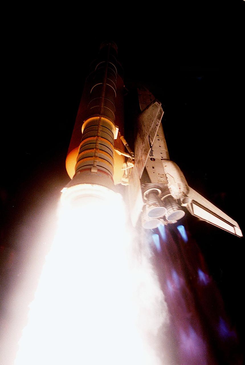
KENNEDY SPACE CENTER, Fla. -- Space Shuttle Discovery roars through the sky trailing fire and blue mach diamonds from the engines. The perfect on-time liftoff at 7:17 p.m. EDT sends a crew of seven on a construction flight to the International Space Station on mission STS-92, the 100th in the history of the Shuttle program. Discovery also carries a payload that includes the Integrated Truss Structure Z-1, first of 10 trusses that will form the backbone of the Space Station, and the third Pressurized Mating Adapter that will provide a Shuttle docking port for solar array installation on the sixth Station flight and Lab installation on the seventh Station flight. Discovery’s landing is expected Oct. 22 at 2:10 p.m. EDT
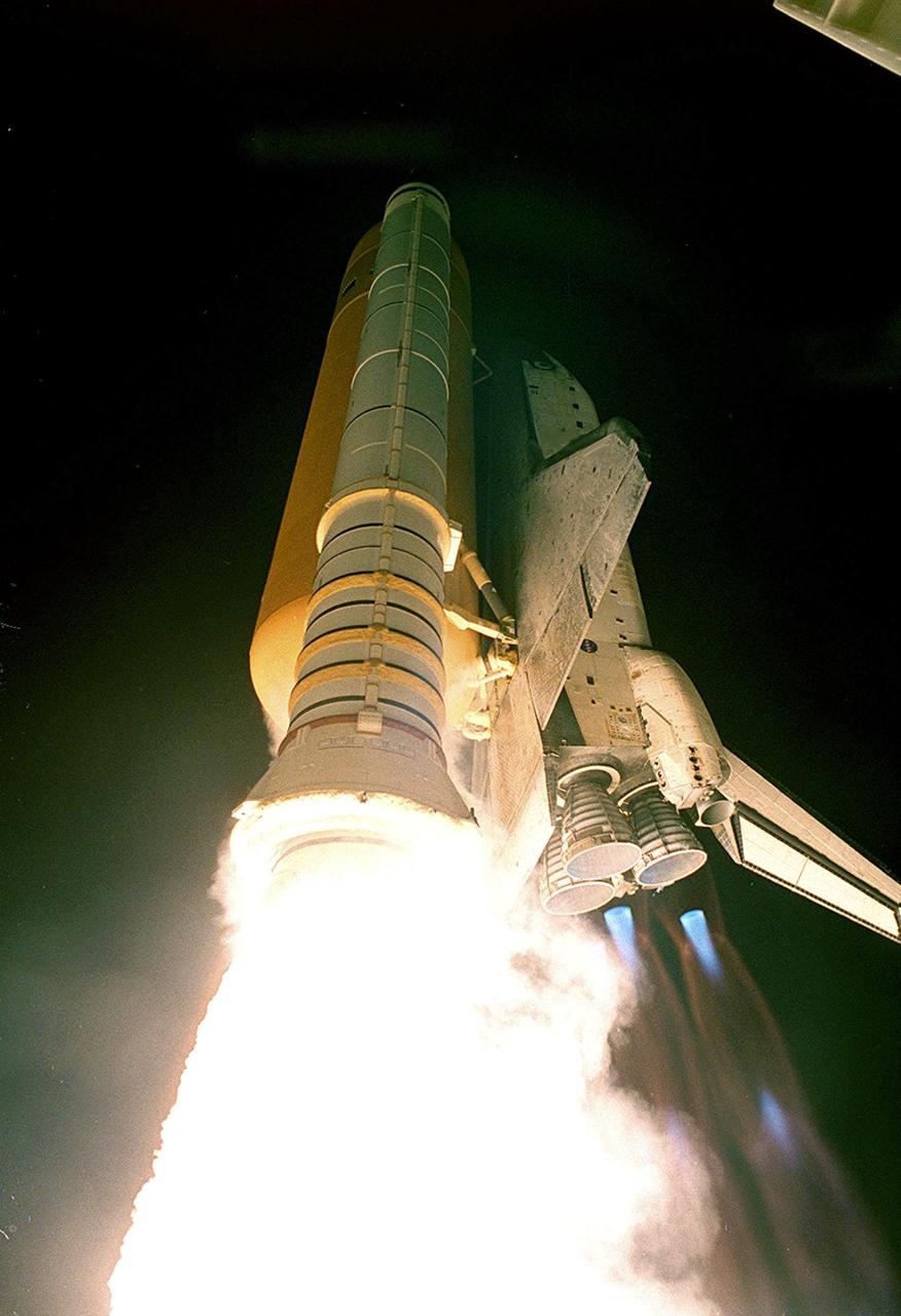
KENNEDY SPACE CENTER, Fla. -- The brilliant exhaust from the solid rocket boosters (left) and blue mach diamonds from the main engine nozzles (right) mark the perfect launch of Space Shuttle Atlantis on mission STS-101. Liftoff occurred on time at 6:11:10 a.m. EDT. The mission is taking the crew of seven to the International Space Station to deliver logistics and supplies as well as to prepare the Station for the arrival of the Zvezda Service Module, expected to be launched by Russia in July 2000. Also, the crew will conduct one space walk and will reboost the space station from 230 statute miles to 250 statute miles. This will be the third assembly flight to the Space Station. After a 10-day mission, landing is targeted for May 29 at 2:19 a.m. EDT. This is the 98th Shuttle flight and the 21st flight for Shuttle Atlantis

KENNEDY SPACE CENTER, Fla. -- The brilliant exhaust from the solid rocket boosters (left) and blue mach diamonds from the main engine nozzles (right) mark the perfect launch of Space Shuttle Atlantis on mission STS-101. Liftoff occurred on time at 6:11:10 a.m. EDT. The mission is taking the crew of seven to the International Space Station to deliver logistics and supplies as well as to prepare the Station for the arrival of the Zvezda Service Module, expected to be launched by Russia in July 2000. Also, the crew will conduct one space walk and will reboost the space station from 230 statute miles to 250 statute miles. This will be the third assembly flight to the Space Station. After a 10-day mission, landing is targeted for May 29 at 2:19 a.m. EDT. This is the 98th Shuttle flight and the 21st flight for Shuttle Atlantis

KENNEDY SPACE CENTER, Fla. -- Space Shuttle Discovery roars through the sky trailing fire and blue mach diamonds from the engines. The perfect on-time liftoff at 7:17 p.m. EDT sends a crew of seven on a construction flight to the International Space Station on mission STS-92, the 100th in the history of the Shuttle program. Discovery also carries a payload that includes the Integrated Truss Structure Z-1, first of 10 trusses that will form the backbone of the Space Station, and the third Pressurized Mating Adapter that will provide a Shuttle docking port for solar array installation on the sixth Station flight and Lab installation on the seventh Station flight. Discovery’s landing is expected Oct. 22 at 2:10 p.m. EDT
A mechanic checks the tubing on one of the many jacks which control the nozzle section of the 10- by 10-Foot Supersonic Wind Tunnel at the National Advisory Committee for Aeronautics (NACA) Lewis Flight Propulsion Laboratory. The 10- by 10-foot tunnel, which had its official opening in May 1956, was built under the Congressional Unitary Plan Act which coordinated wind tunnel construction at the NACA, Air Force, industry, and universities. The 10- by 10 was the largest of the three NACA tunnels built under the act. The 10- by 10 wind tunnel can be operated as a closed circuit for aerodynamic tests or as an open circuit for propulsion investigations. The 10-foot tall and 76-foot long stainless steel nozzle section just upstream from the test section can be adjusted to change the speed and composition of the air flow. Hydraulic jacks, seen in this photograph, flex the 1.37-inch thick walls of the tunnel nozzle. The size of the nozzle’s opening controls the velocity of the air through the test section. Seven General Electric motors capable of generating 25,000 horsepower produce the Mach 2.5 and 2.5 airflows. The facility was mostly operated at night due to its large power load requirements.
The first of three X-43A hypersonic research aircraft and its modified Pegasus® booster rocket recently underwent combined systems testing while mounted to NASA's NB-52B carrier aircraft at the Dryden Flight Research Center, Edwards, California. The combined systems test was one of the last major milestones in the Hyper-X research program before the first X-43A flight. One of the major goals of the Hyper-X program is flight validation of airframe-integrated, air-breathing propulsion system, which so far have only been tested in ground facilities, such as wind tunnels. The X-43A flights will be the first actual flight tests of an aircraft powered by a revolutionary supersonic-combustion ramjet ("scramjet") engine capable of operating at hypersonic speeds above Mach 5 (five times the speed of sound). The X-43A design uses the underbody of the aircraft to form critical elements of the engine. The forebody shape helps compress the intake airflow, while the aft section acts as a nozzle to direct thrust. The 12-foot, unpiloted research vehicle was developed and built by MicroCraft Inc., Tullahoma, Tenn., under NASA contract. The booster, built by Orbital Sciences Corp., Dulles, Va., will accelerate the X-43A after the X-43A/booster "stack" is air-launched from NASA's venerable NB-52 mothership. The X-43A will separate from the rocket at a predetermined altitude and speed and fly a pre-programmed trajectory, conducting aerodynamic and propulsion experiments until it descends into the Pacific Ocean. Three research flights are planned, two at Mach 7 and one at Mach 10.
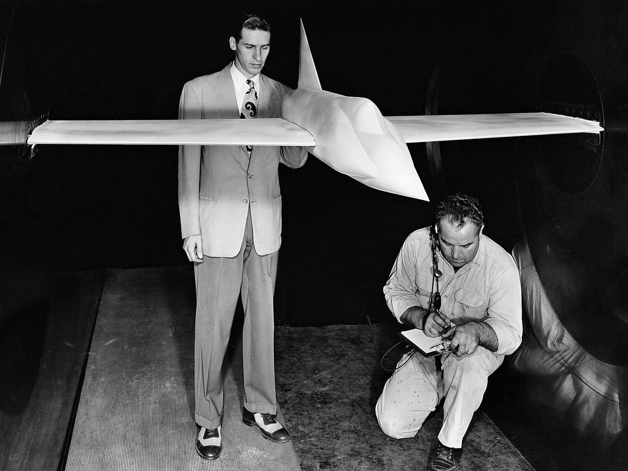
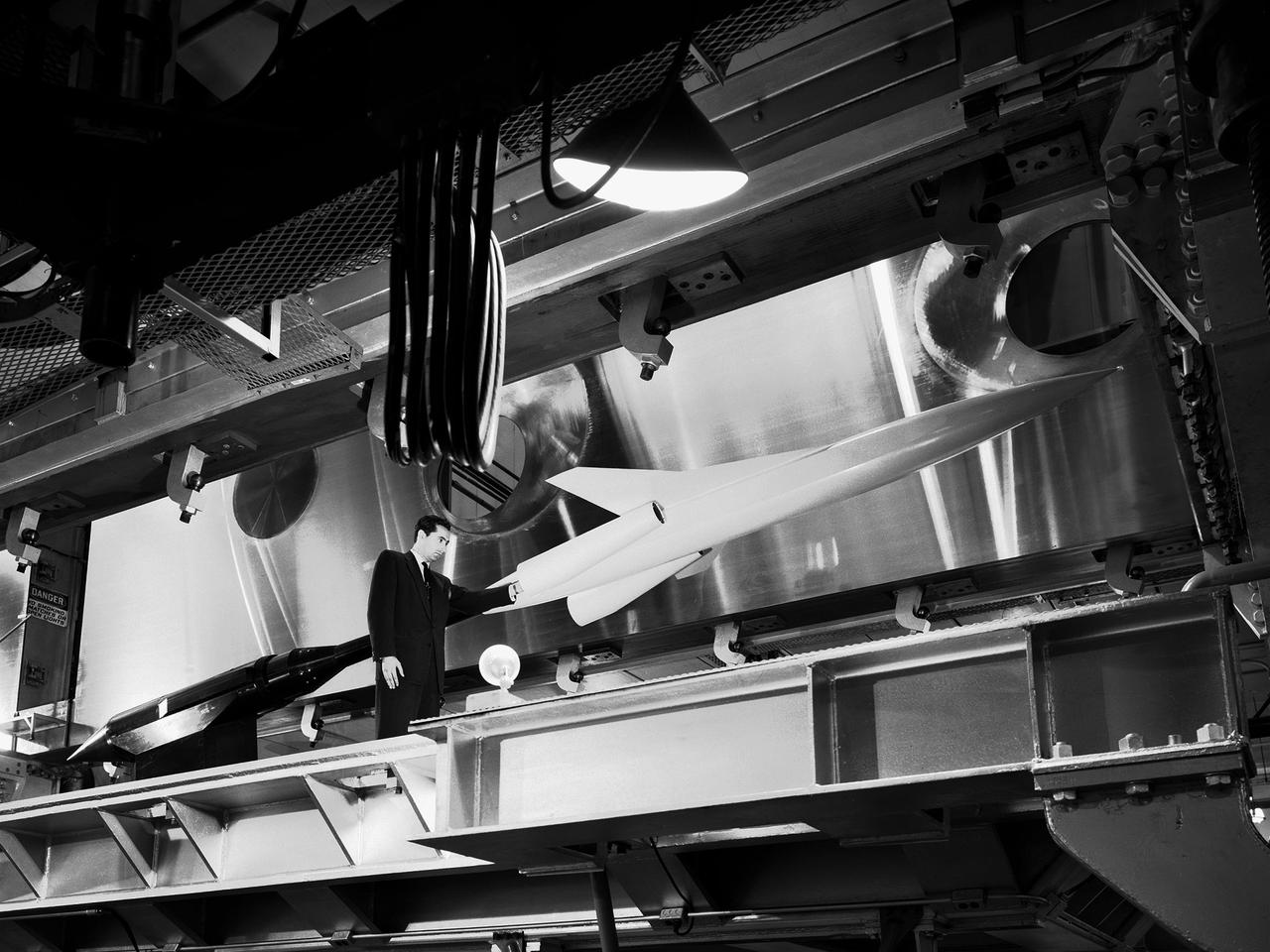
A .10-scale model of Convair’s XF-102 in the 8- by 6-Foot Supersonic Wind Tunnel at the National Advisory Committee for Aeronautics (NACA) Lewis Flight Propulsion Laboratory for jet exit studies. The XF-102 was a prototype of the F-102 Delta Dagger. The F-102 served as an interceptor against long range bombers from the Soviet Union. The aircraft was powered by a Pratt and Whitney J57 turbojet. The first prototype crashed two weeks after is first flight on October 24, 1953, just months after this photograph. Engineers then incorporated the fixed-wing design to reduce drag at supersonic speeds. The production model F-102 became the first delta-wing supersonic aircraft in operation. The 8- by 6-Foot Supersonic Wind Tunnel is used to study propulsion systems, including inlets and exit nozzles, combustion fuel injectors, flame holders, exit nozzles, and controls on ramjet and turbojet engines. Flexible sidewalls alter the tunnel’s nozzle shape to vary the Mach number during operation. A seven-stage axial compressor, driven by three electric motors that yield a total of 87,000 horsepower, generates air speeds from Mach 0.36 to 2.0.
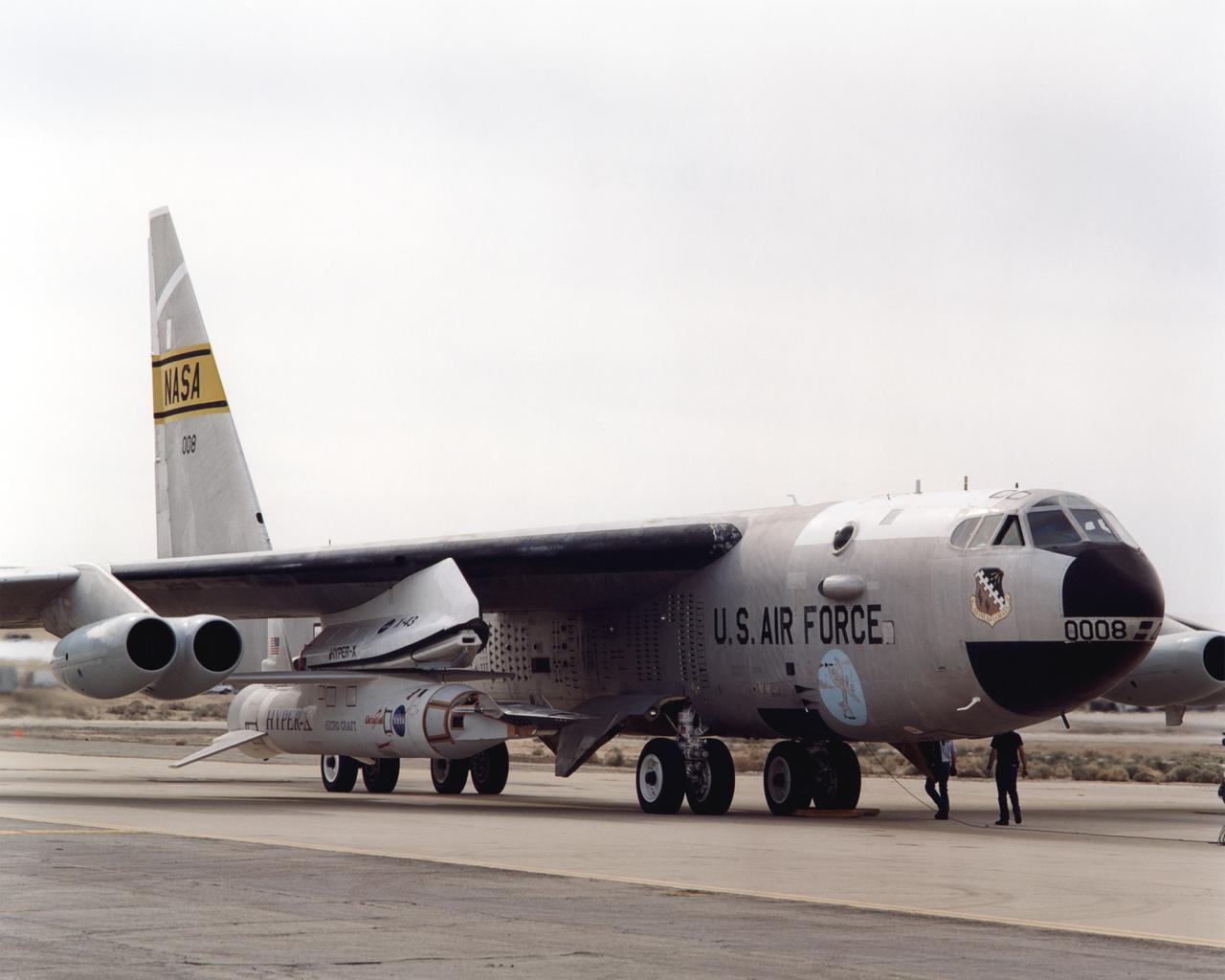
Attached to the same B-52B mothership that once launched X-15 research aircraft in the 1960s, NASA's third X-43A performed a captive carry evaluation flight from Edwards Air Force Base, California on September 27, 2004. The X-43 remained mated to the B-52 throughout this mission, intended to check its readiness for launch scheduled later in the fall.
Attached to the same B-52B mothership that once launched X-15 research aircraft in the 1960s, NASA's third X-43A performed a captive carry evaluation flight from Edwards Air Force Base, California on September 27, 2004. The X-43 remained mated to the B-52 throughout this mission, intended to check its readiness for launch scheduled later in the fall.
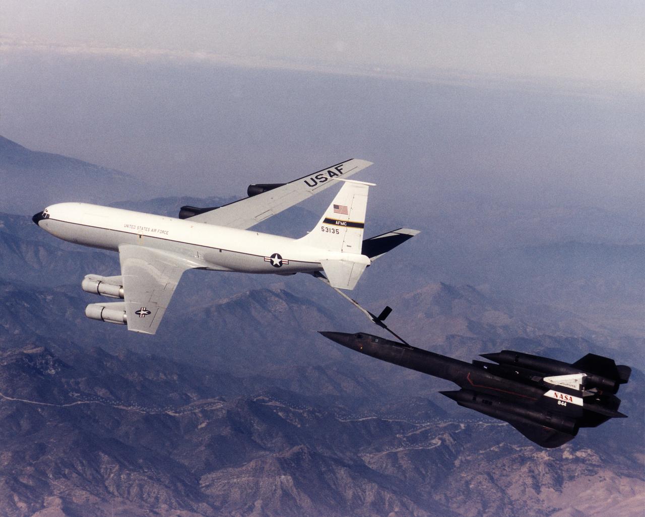
A NASA SR-71 refuels with an Edwards Air Force Base KC-135 during the first flight of the NASA/Rocketdyne/ Lockheed Martin Linear Aerospike SR-71 Experiment (LASRE). The flight took place Oct. 31 at NASA's Dryden Flight Research Center, Edwards, California. The SR-71 took off at 8:31 a.m. PST. The aircraft flew for one hour and fifty minutes, reaching a maximum speed of Mach 1.2 before landing at Edwards at 10:21 a.m. PST, successfully validating the SR-71/linear aerospike experiment configuration. The goal of the first flight was to evaluate the aerodynamic characteristics and the handling of the SR-71/linear aerospike experiment configuration. The engine was not fired during the flight.
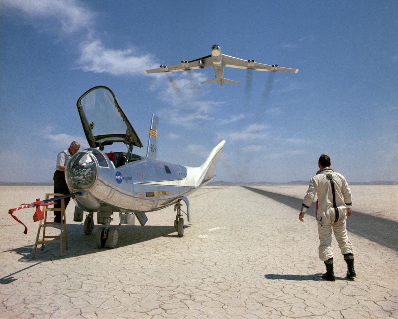
The HL-10 was one of five heavyweight lifting-body designs flown at NASA's Flight Research Center (FRC--later Dryden Flight Research Center), Edwards, California, from July 1966 to November 1975 to study and validate the concept of safely maneuvering and landing a low lift-over-drag vehicle designed for reentry from space. Northrop Corporation built the HL-10 and M2-F2, the first two of the fleet of "heavy" lifting bodies flown by the NASA Flight Research Center. The contract for construction of the HL-10 and the M2-F2 was $1.8 million. "HL" stands for horizontal landing, and "10" refers to the tenth design studied by engineers at NASA's Langley Research Center, Hampton, Va. After delivery to NASA in January 1966, the HL-10 made its first flight on Dec. 22, 1966, with research pilot Bruce Peterson in the cockpit. Although an XLR-11 rocket engine was installed in the vehicle, the first 11 drop flights from the B-52 launch aircraft were powerless glide flights to assess handling qualities, stability, and control. In the end, the HL-10 was judged to be the best handling of the three original heavy-weight lifting bodies (M2-F2/F3, HL-10, X-24A). The HL-10 was flown 37 times during the lifting body research program and logged the highest altitude and fastest speed in the Lifting Body program. On Feb. 18, 1970, Air Force test pilot Peter Hoag piloted the HL-10 to Mach 1.86 (1,228 mph). Nine days later, NASA pilot Bill Dana flew the vehicle to 90,030 feet, which became the highest altitude reached in the program. Some new and different lessons were learned through the successful flight testing of the HL-10. These lessons, when combined with information from it's sister ship, the M2-F2/F3, provided an excellent starting point for designers of future entry vehicles, including the Space Shuttle.
The 10- by 10-Foot Supersonic Wind Tunnel at the NACA Lewis Flight Propulsion Laboratory was built under the Congressional Unitary Plan Act which coordinated wind tunnel construction at the NACA, Air Force, industry, and universities. The 10- by 10, which began operation in 1956, was the largest of the three NACA tunnels built under the act. Researchers could test engines up to five feet in diameter in the 10- by 10-foot test section. A 250,000-horsepower axial-flow compressor fan can generate airflows up to Mach 3.5 through the test section. The incoming air must be dehumidified and cooled so that the proper conditions are present for the test. A large air dryer with 1,890 tons of activated alumina soaks up 1.5 tons of water per minute from the airflow. A cooling apparatus equivalent to 250,000 household air conditioners is used to cool the air. The air heater is located just upstream from the test section. Natural gas is combusted in the tunnel to increase the air temperature. The system could only be employed when the tunnel was run in its closed-circuit propulsion mode.
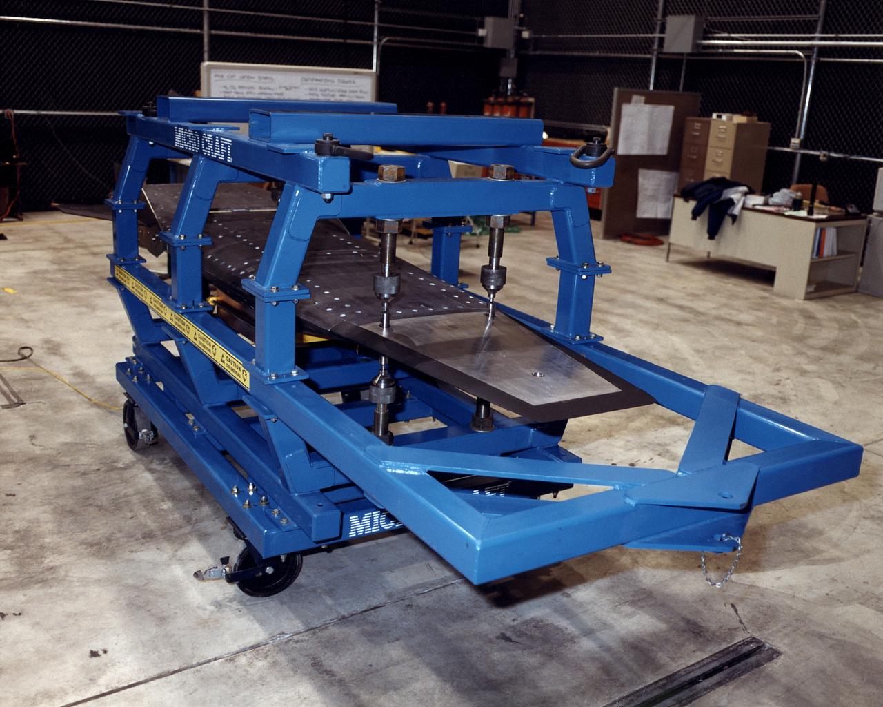
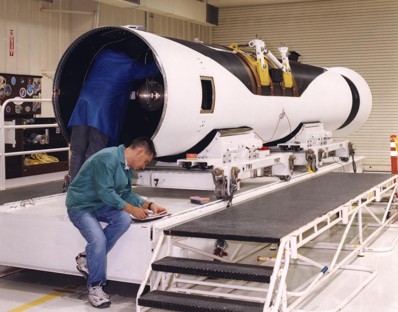
The second of three X-43A hypersonic research aircraft, shown here in its protective shipping jig, arrived at NASA's Dryden Flight Research Center, Edwards, California, on January 31, 2001. The arrival of the second X-43A from its manufacturer, MicroCraft, Inc., of Tullahoma, Tenn., followed by only a few days the mating of the first X-43A and its specially-designed adapter to the first stage of a modified Pegasus® booster rocket. The booster, built by Orbital Sciences Corp., Dulles, Va., will accelerate the 12-foot-long, unpiloted research aircraft to a predetermined altitude and speed after the X-43A/booster "stack" is air-launched from NASA's venerable NB-52 mothership. The X-43A will then separate from the rocket and fly a pre-programmed trajectory, conducting aerodynamic and propulsion experiments until it impacts into the Pacific Ocean. Three research flights are planned, two at Mach 7 and one at Mach 10 (seven and 10 times the speed of sound respectively) with the first tentatively scheduled for early summer, 2001. The X-43A is powered by a revolutionary supersonic-combustion ramjet ("scramjet") engine, and will use the underbody of the aircraft to form critical elements of the engine. The forebody shape helps compress the intake airflow, while the aft section acts as a nozzle to direct thrust. The X-43A flights will be the first actual flight tests of an aircraft powered by an air-breathing scramjet engine.
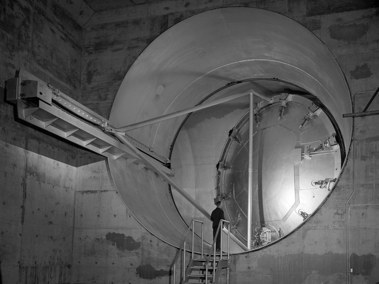
A 24-foot diameter swing valve is seen in an open position inside the new 10- by 10-Foot Supersonic Wind Tunnel at the National Advisory Committee for Aeronautics (NACA) Lewis Flight Propulsion Laboratory. The 10- by 10 was the most powerful propulsion wind tunnel in the nation. After over three years of construction the tunnel was ready to conduct its first tests in early 1956. The 10- by 10-foot tunnel was part of Congress’ Unitary Plan Act which coordinated wind tunnel construction at the NACA, Air Force, industry, and universities. The 10- by 10 was the largest of the three NACA tunnels built under the act. This large swinging valve is critical to the operation of the facility. In one position the valve seals off the tunnel exhaust, making the tunnel a closed circuit, which is used for aerodynamic testing of models. In its other position, the valve acts as a seal across the tunnel and leaves the tunnel exhaust open. This arrangement is used when engines are fired. The air going through the tunnel is taken from the atmosphere and returned to the atmosphere after one pass through the tunnel. Engines up to five feet in diameter can be tested in the 10- by 10-foot test section. Air flows up to Mach 3.5 can be fed through the test section by a 250,000-horsepower axial-flow compressor fan. The incoming air must be dehumidified and cooled so that the proper conditions are present for the test. A large air dryer with 1,890 tons of activated alumina soaks up 1.5 tons of water per minute from the air flow. A cooling apparatus equivalent to 250,000 household air conditioners is used to cool the air.
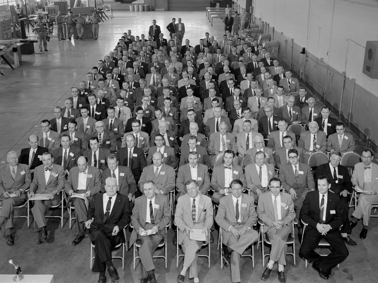
Attendees listen during the May 22, 1956 Inspection of the new 10- by 10-Foot Supersonic Wind Tunnel at the National Advisory Committee for Aeronautics (NACA) Lewis Flight Propulsion Laboratory. The facility, known at the time as the Lewis Unitary Plan Tunnel, was in its initial stages of operation. The $33 million 10- by 10 was the most powerful wind tunnel in the nation. Over 150 guests from industry, other NACA laboratories, and the media attended the event. The speakers, from left to right in the front row, addressed the crowd before the tour. Lewis Director Raymond Sharp began the event by welcoming the visitors to the laboratory. NACA Director Hugh Dryden discussed Congress’ Unitary Plan Act and its effect on the creation of the facility. Lewis Associate Director Abe Silverstein discussed the need for research tools and the 10- by 10’s place among the NACA’s other research facilities. Lewis Assistant Director Eugene Wasielewski described the detailed design work that went into the facility. Carl Schueller, Chief of the 10- by 10, described the tunnel’s components and how the facility operated. Robert Godman led the tour afterwards. The 10- by 10 can test engines up to five feet in diameter at supersonic speeds and simulated altitudes of 30 miles. Its main purpose is to investigate problems relating to engine inlet and outlet geometry, engine matching and interference effects, and overall drag. The tunnel’s 250,000-horsepower electric motor drive, the most powerful of its kind in the world, creates air speeds between Mach 2.0 and 3.5.
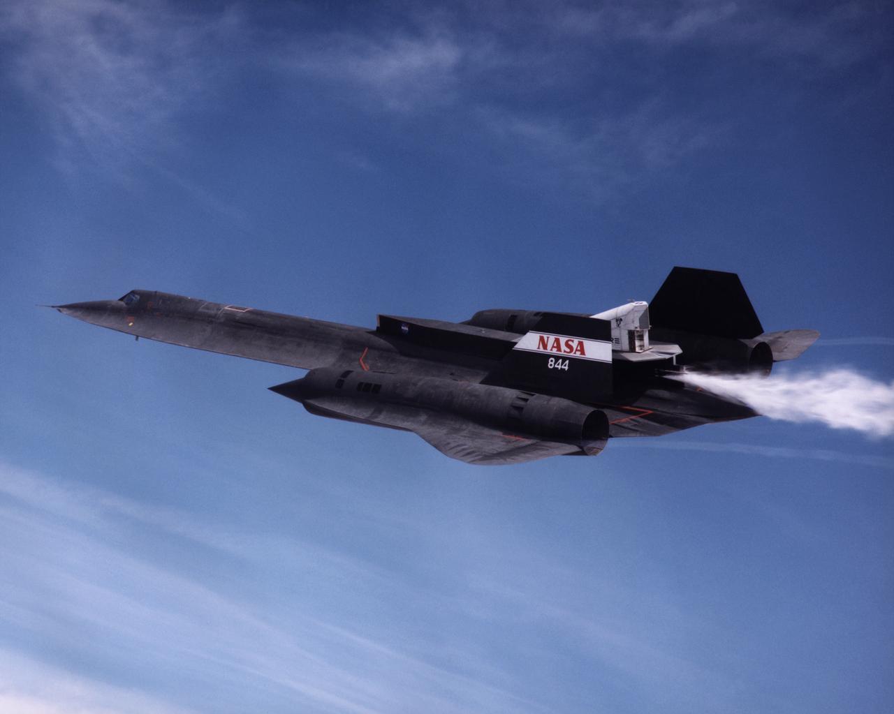
The NASA SR-71A successfully completed its first cold flow flight as part of the NASA/Rocketdyne/Lockheed Martin Linear Aerospike SR-71 Experiment (LASRE) at NASA's Dryden Flight Research Center, Edwards, California on March 4, 1998. During a cold flow flight, gaseous helium and liquid nitrogen are cycled through the linear aerospike engine to check the engine's plumbing system for leaks and to check the engine operating characterisitics. Cold-flow tests must be accomplished successfully before firing the rocket engine experiment in flight. The SR-71 took off at 10:16 a.m. PST. The aircraft flew for one hour and fifty-seven minutes, reaching a maximum speed of Mach 1.58 before landing at Edwards at 12:13 p.m. PST. "I think all in all we had a good mission today," Dryden LASRE Project Manager Dave Lux said. Flight crew member Bob Meyer agreed, saying the crew "thought it was a really good flight." Dryden Research Pilot Ed Schneider piloted the SR-71 during the mission. Lockheed Martin LASRE Project Manager Carl Meade added, "We are extremely pleased with today's results. This will help pave the way for the first in-flight engine data-collection flight of the LASRE."

An artist's rendering of the air-breathing, hypersonic X-43B, the third and largest of NASA's Hyper-X series flight demonstrators, which could fly later this decade. Revolutionizing the way we gain access to space is NASA's primary goal for the Hypersonic Investment Area, managed for NASA by the Advanced Space Transportation Program at the Marshall Space Flight Center in Huntsville, Alabama. The Hypersonic Investment area, which includes leading-edge partners in industry and academia, will support future generation reusable vehicles and improved access to space. These technology demonstrators, intended for flight testing by decade's end, are expected to yield a new generation of vehicles that routinely fly about 100,000 feet above Earth's surface and reach sustained speeds in excess of Mach 5 (3,750 mph), the point at which "supersonic" flight becomes "hypersonic" flight. The flight demonstrators, the Hyper-X series, will be powered by air-breathing rocket or turbine-based engines, and ram/scramjets. Air-breathing engines, known as combined-cycle systems, achieve their efficiency gains over rocket systems by getting their oxygen for combustion from the atmosphere, as opposed to a rocket that must carry its oxygen. Once a hypersonic vehicle has accelerated to more than twice the speed of sound, the turbine or rockets are turned off, and the engine relies solely on oxygen in the atmosphere to burn fuel. When the vehicle has accelerated to more than 10 to 15 times the speed of sound, the engine converts to a conventional rocket-powered system to propel the craft into orbit or sustain it to suborbital flight speed. NASA's series of hypersonic flight demonstrators includes three air-breathing vehicles: the X-43A, X-43B and X-43C.