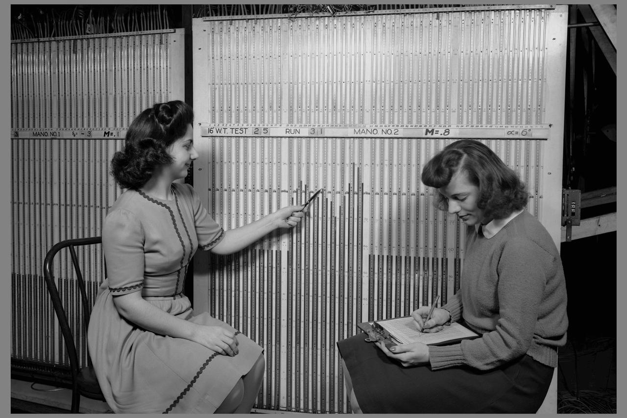
Computers' at work in 16ft wind tunnel - calculating test data - reading manometer board
Instrumentation in 16 Foot Wind Tunnel manometer boards
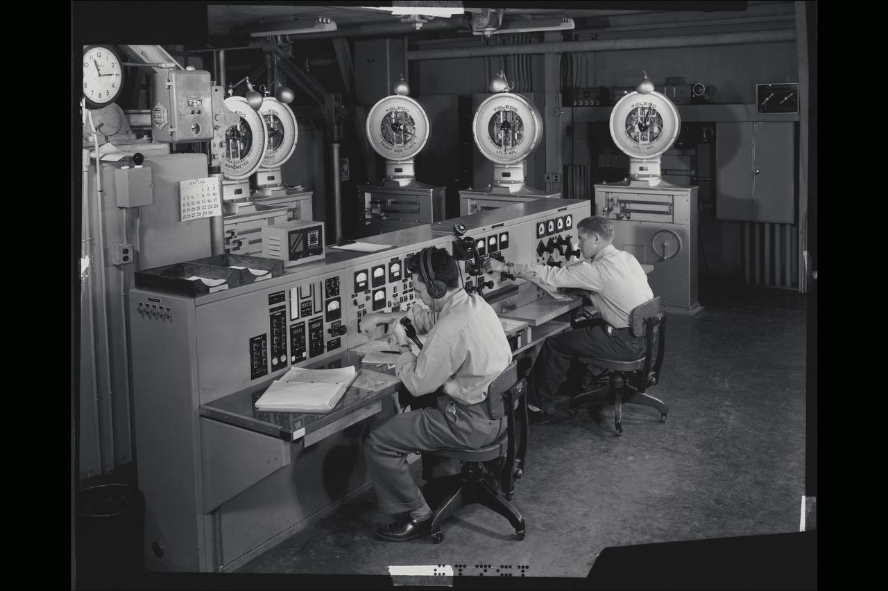
40x80 wind tunnel manometers control room at NACA's Ames Research Center. Control panel (called the bench board) showing five of the seven scale heads which measured the forces on the model (ie. Lift, drag, side force etc.)
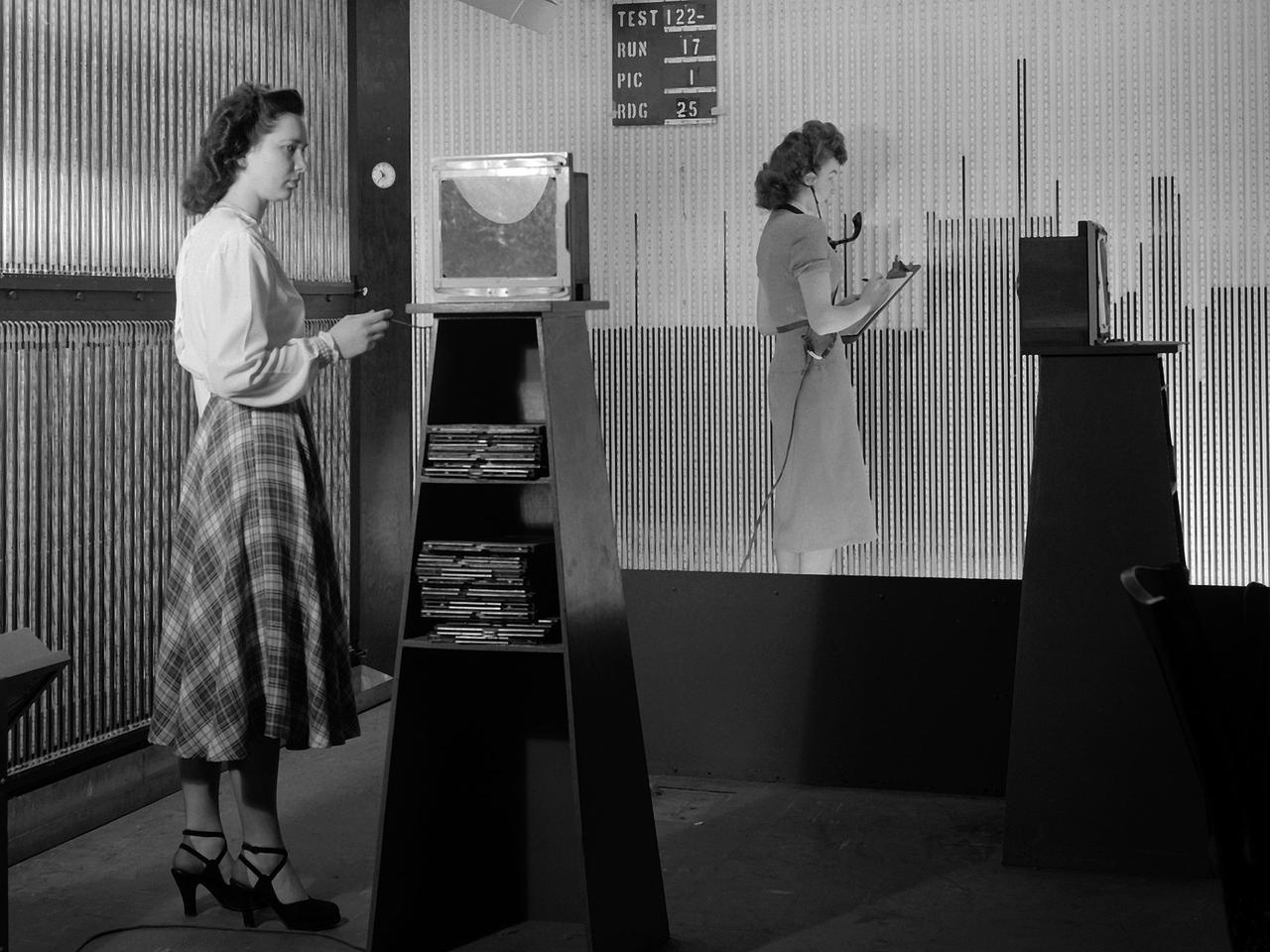
Female computers at the National Advisory Committee for Aeronautics (NACA) Lewis Flight Propulsion Laboratory copy pressure readings from rows of manometers below the 18- by 18-inch Supersonic Wind Tunnel. The computers obtained test data from the manometers and other instruments, made the initial computations, and plotted the information graphically. Based on these computations, the researchers planned their next test or summarized their findings in a report. Manometers were mercury-filled glass tubes that were used to indicate different pressure levels from inside the test facility or from the test article. Manometers look and function very similarly to thermometers. Dozens of pressure sensing instruments were installed for each test. Each was connected to a manometer tube located inside the control room. The mercury inside the manometer rose and fell with the pressure levels. The dark mercury can be seen in this photograph at different levels within the tubes. Since this activity was dynamic, it was necessary to note the levels at given points during the test. This was done using both computer notations and photography.
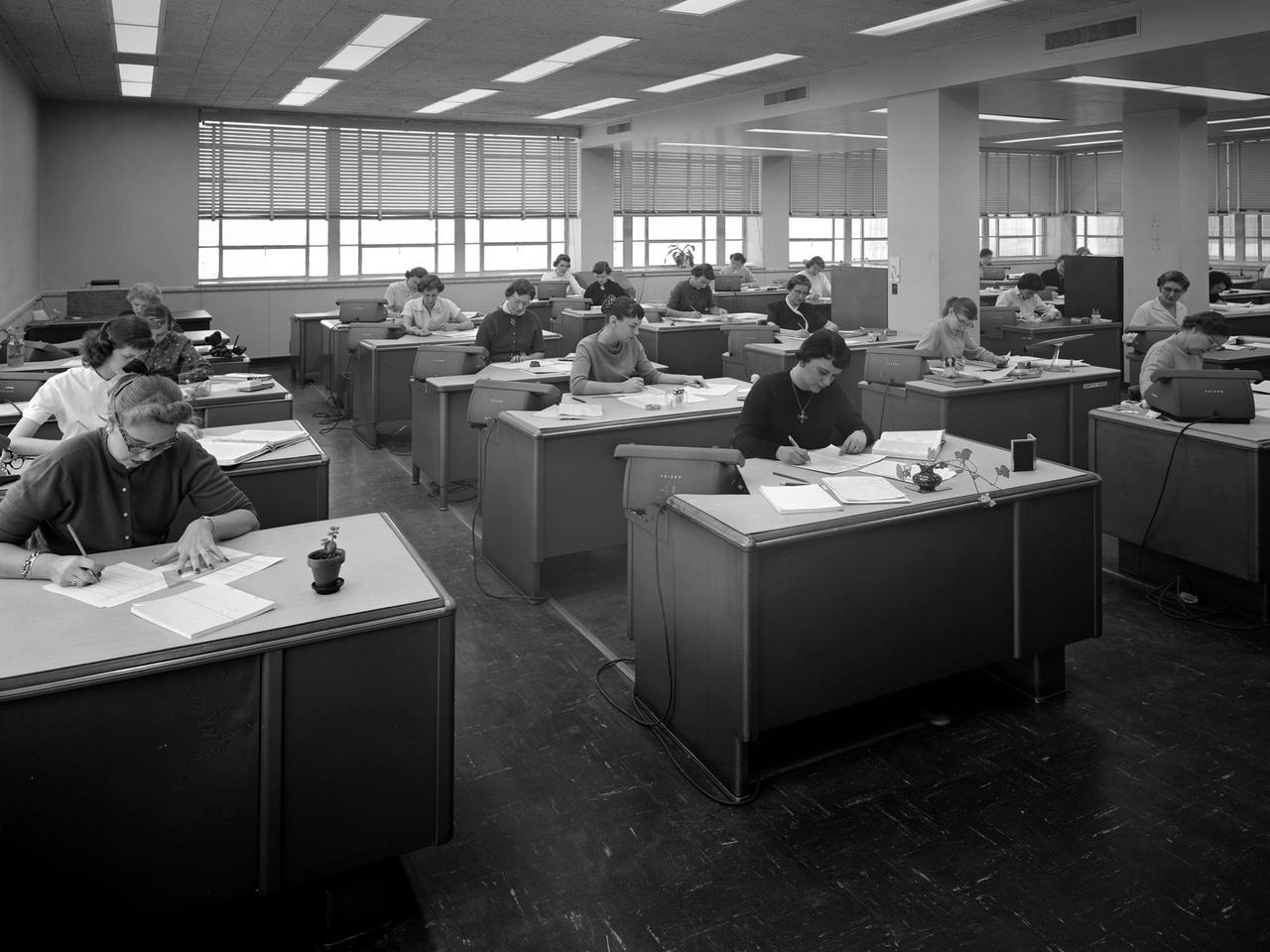
The staff of female computers at work in the 8- by 6-Foot Supersonic Wind Tunnel at the National Advisory Committee for Aeronautics (NACA) Lewis Flight Propulsion Laboratory. The lab’s Computer Section occupied three offices on the second story of the office building at the 8- by 6 facility. The largest office, seen in this photograph, contained approximately 35 women with advanced mathematical skills, a second office housed 20 to 25, and a third 10. Each major test facility at the laboratory had banks of mercury-filled manometer boards which measured pressure levels at various locations inside the facility’s test section. Often, one board consisting of 100 tubes produced a single data point. There could be scores of data points for each test run. Cameras were set up in front of the manometer boards to capture the readings throughout the test. The following day the computers, seen in this photograph, would receive the photographs and plot the data points on a graph. The process often took days. It might be weeks before the researchers received the results of their tests. The Friden adding machines can be seen on some of the desks.
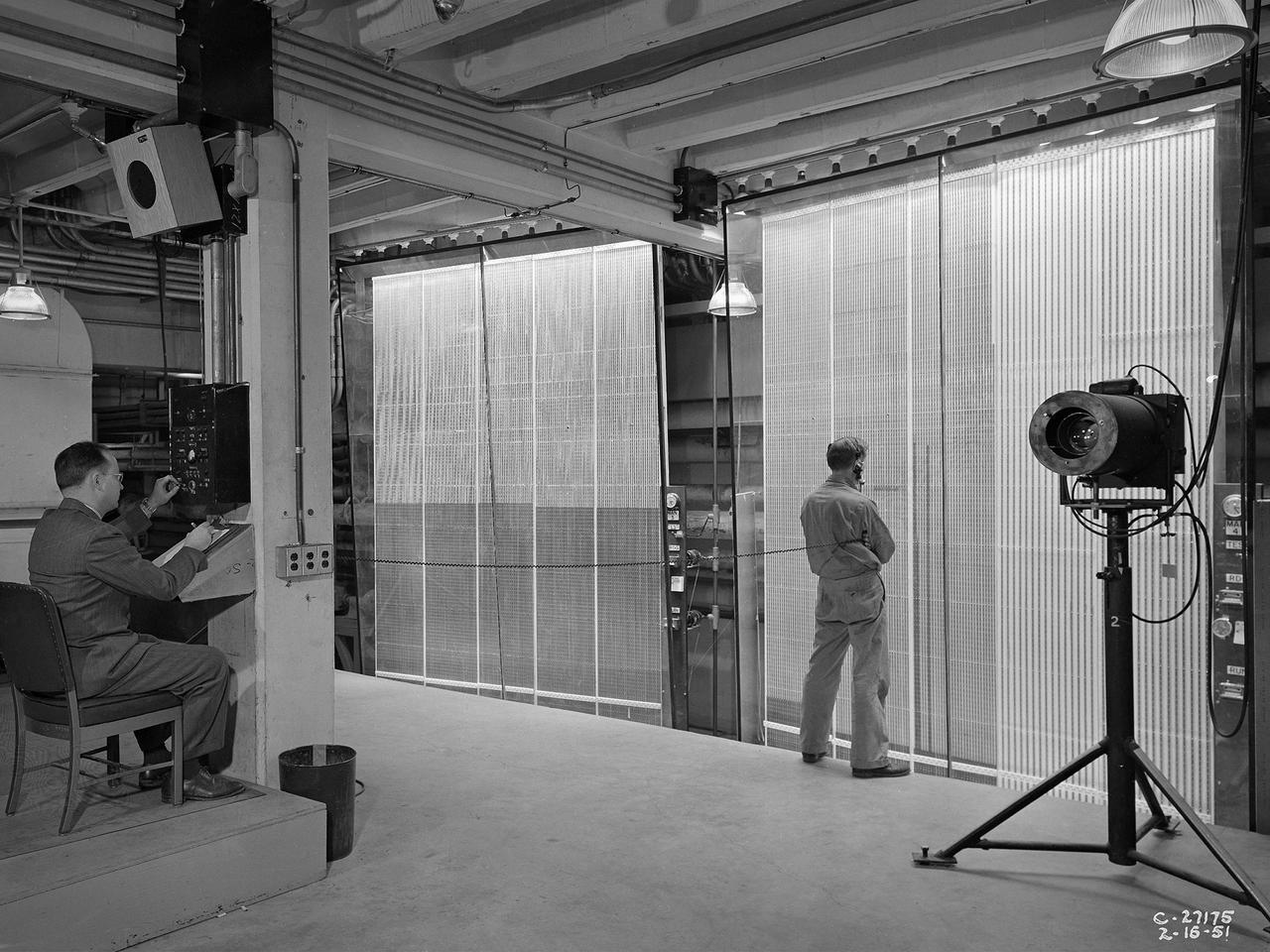
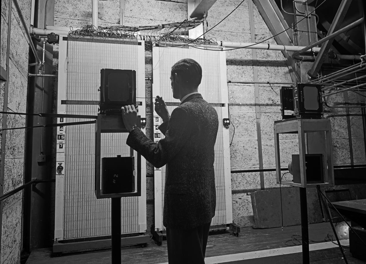
Analysts at the National Advisory Committee for Aeronautics (NACA) Lewis Flight Propulsion Laboratory take data readings from rows of manometers in the basement of the 8- by 6-Foot Supersonic Wind Tunnel. Manometers were mercury-filled glass tubes that indicated different pressure levels in the test section. Manometers look and function very similarly to thermometers. Pressure sensing instruments were installed on the test article inside the wind tunnel or other test facility. Each test could have dozens of such instruments installed and connected to a remotely located manometer tube. The mercury inside the manometer rose and fell with the pressure levels. The dark mercury can be seen at different levels within the tubes. Since the pressure readings were dynamic, it was necessary to note the levels at given points during the test. This was done using both female computers and photography. A camera is seen on a stand to the right in this photograph.

An inlet duct lowered into the 20-foot diameter test section of the Altitude Wind Tunnel at the National Advisory Committee for Aeronautics (NACA) Lewis Flight Propulsion Laboratory. Engines and hardware were prepared in the facility’s shop area. The test articles were lifted by a two-rail Shaw box crane through the high-bay and the second-story test chamber before being lowered into the test section. Technicians then spent days or weeks hooking up the supply lines and data recording telemetry. The engines were mounted on wingspans that stretched across the test section. The wingtips attached to the balance frame’s trunnions, which could adjust the angle of attack. The balance frame included six devices that recorded data and controlled the engine. The measurements were visible in banks of manometer boards next to the control room. Photographs recorded the pressure levels in the manometer tubes, and the computing staff manually converted the data into useful measurements. A mechanical pulley system was used to raise and lower the tunnel’s large clamshell lid into place. The lid was sealed into place using hand-turned locks accessible from the viewing platform. The lid had viewing windows above and below the test article, which permitted the filming and visual inspection of the tests.
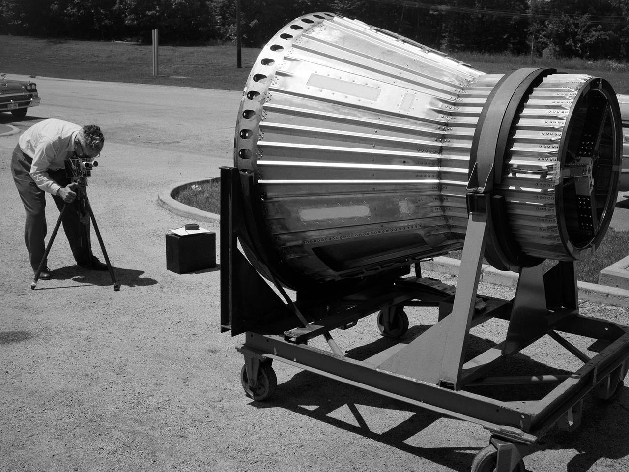
National Aeronautics and Space Administration (NASA) photographer Arthur Laufman sets up a camera to film a Mercury capsule that was constructed by the Lewis Research Center staff. Lewis engineers and mechanics built two of the capsules for the upcoming Big Joe launches in September 1959. Big Joe was an attempt early in Project Mercury to use a full-scale Atlas booster to simulate the reentry of a mock-up Mercury capsule without actually placing it in orbit. The Photographic Branch, referred to as the Photo Lab, was part of the center’s Technical Reports Division. Originally the group performed normal and high-speed still image and motion picture photography. The photographers documented construction, performed publicity work, created images for reports, photographed data on manometer boards, and recorded test footage. Laufman joined the Photo Lab staff in 1948 and began producing full-length technical films as a tool to educate those outside of the agency on the research being conducted at Lewis. He worked with engineers to determine proper subjects for these films and develop a script. Laufman not only filmed tests, but also supporting footage of facilities, models, and staff members. He then edited the footage and added audio, visuals, and narration. The film masters were assigned standard identification numbers and add to the Photo Lab’s catalogue.