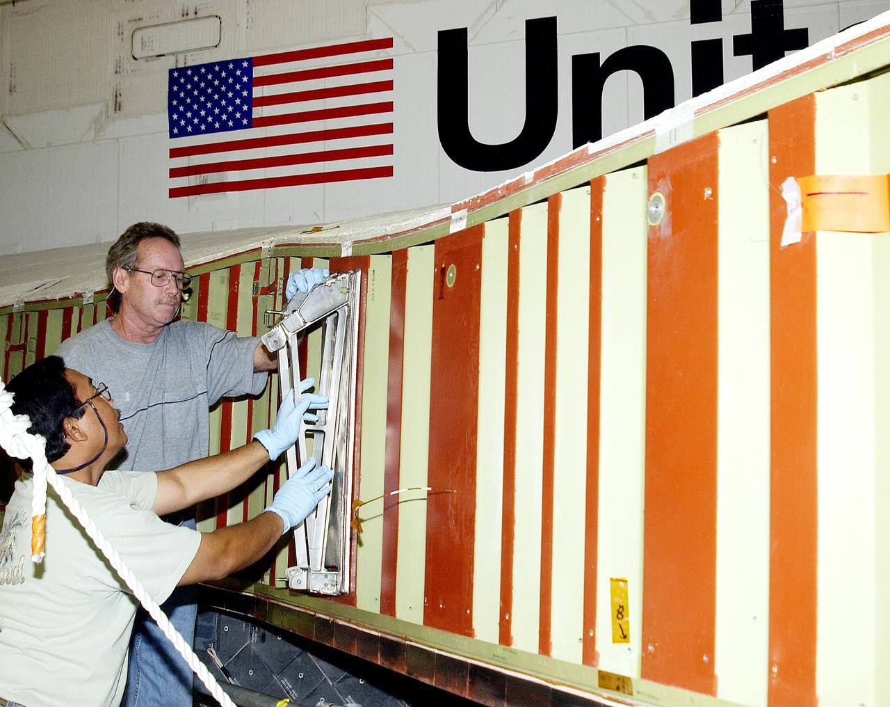
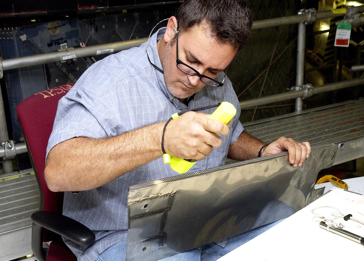
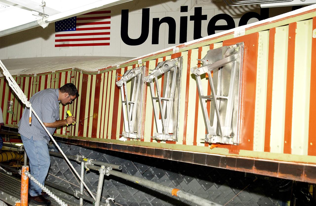
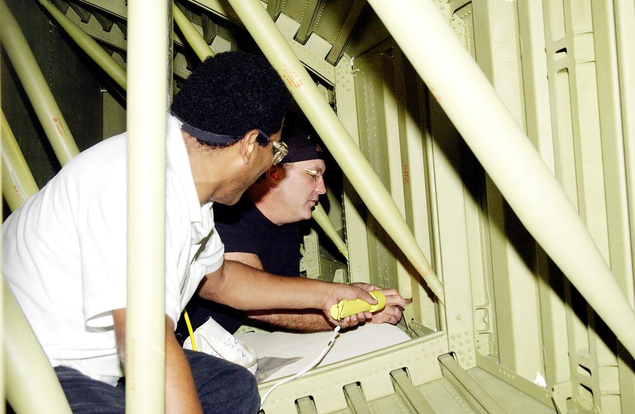
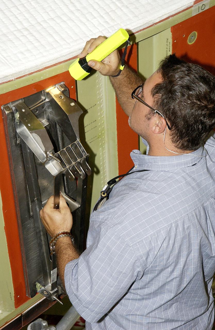
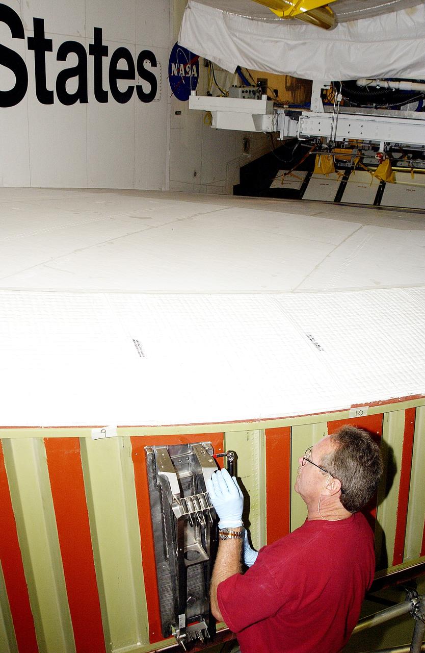
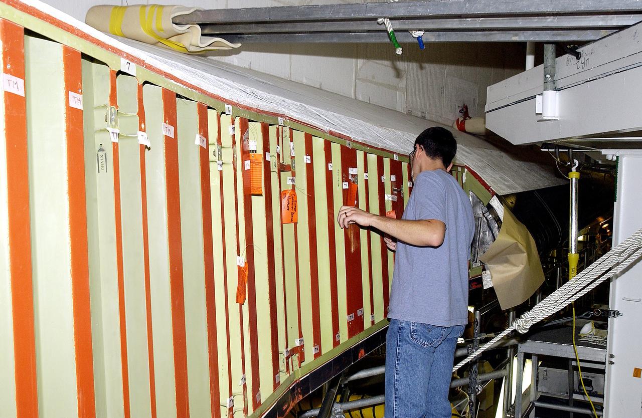
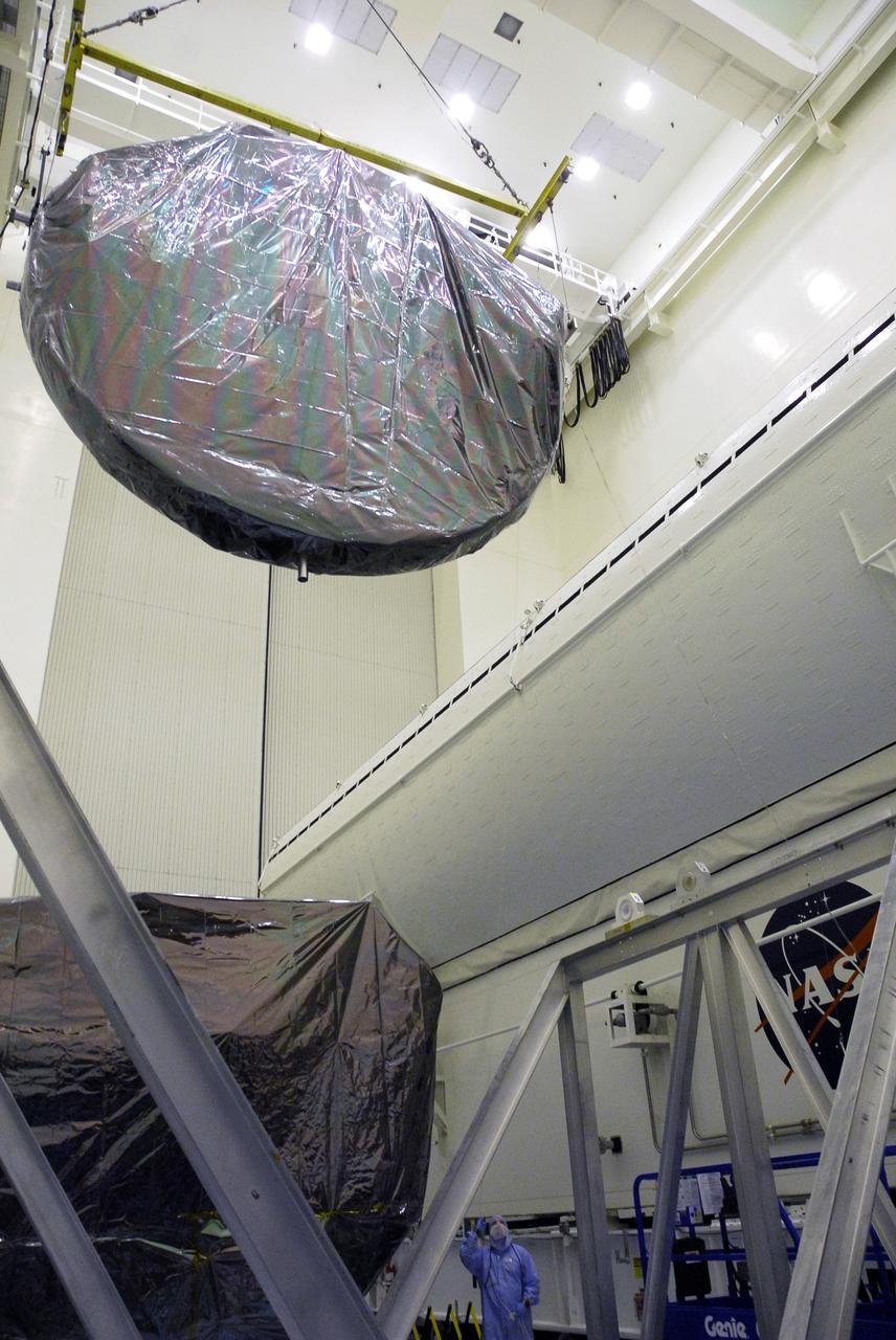
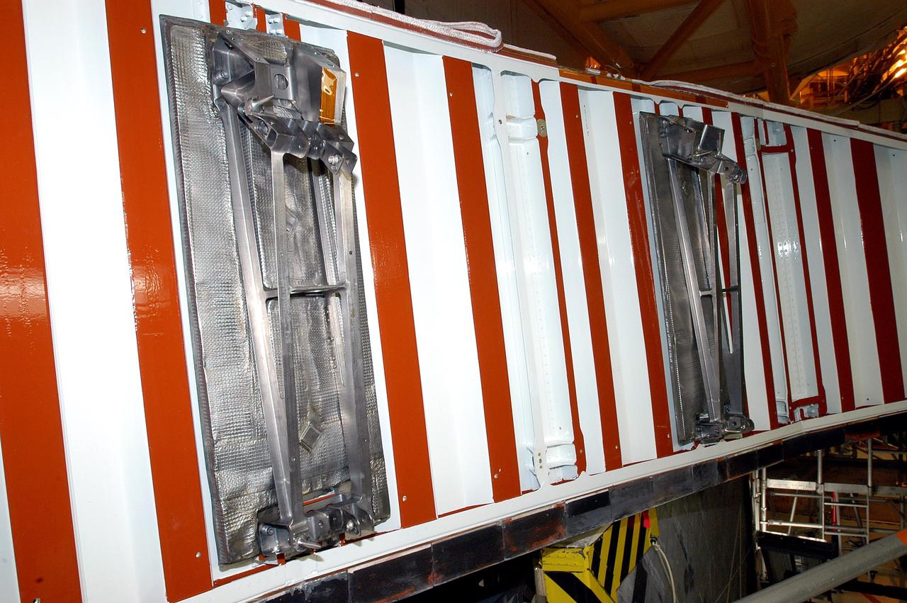
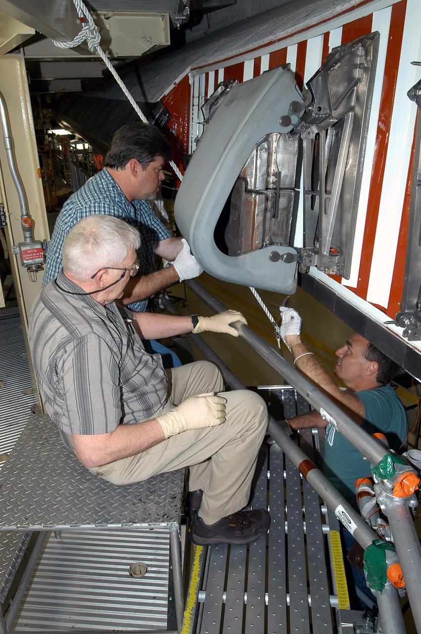
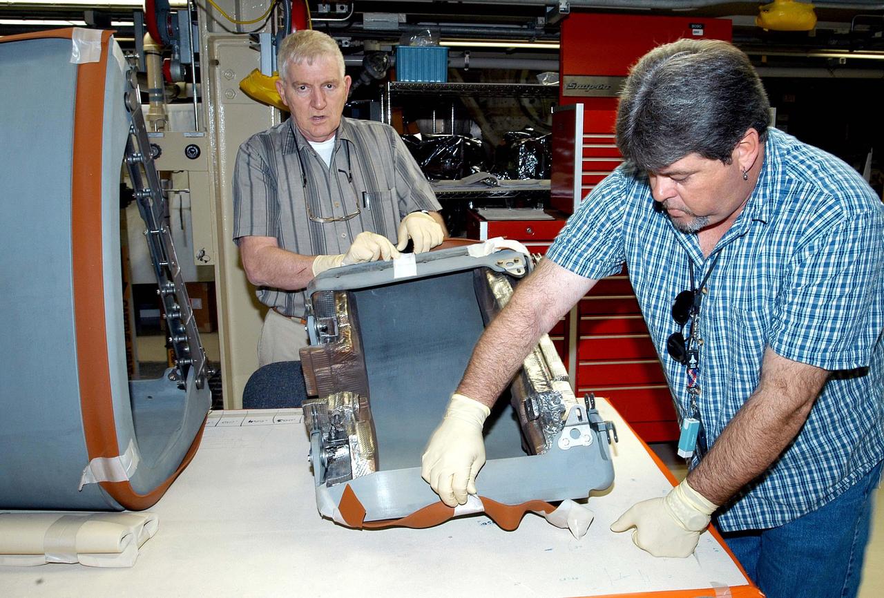
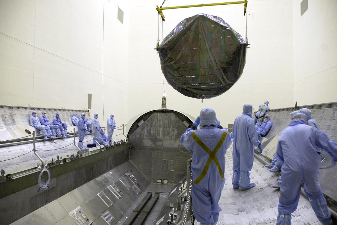
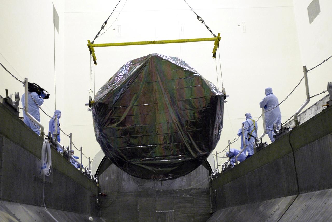
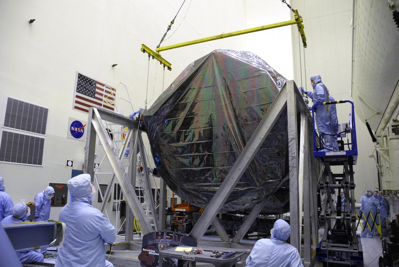
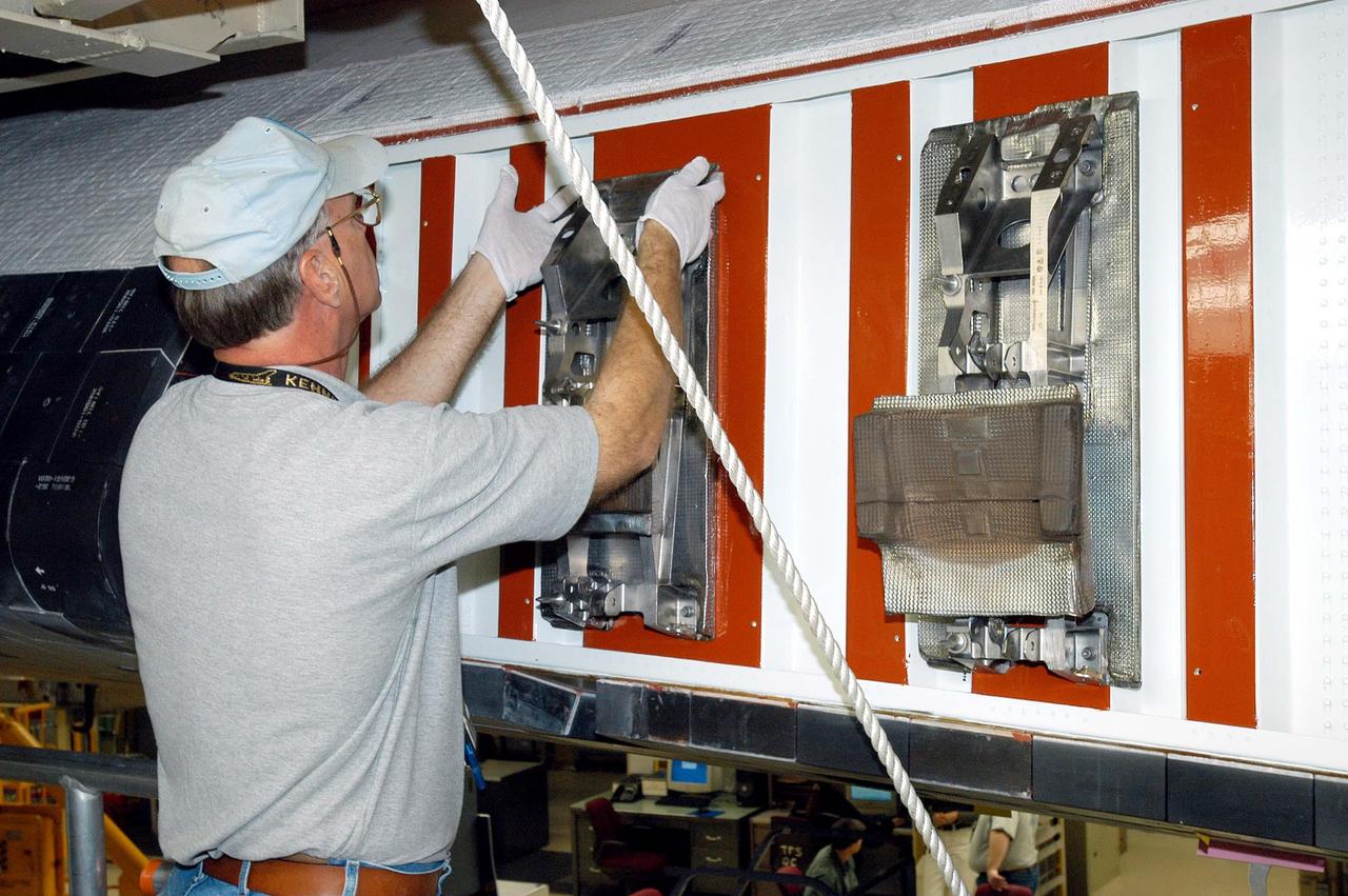
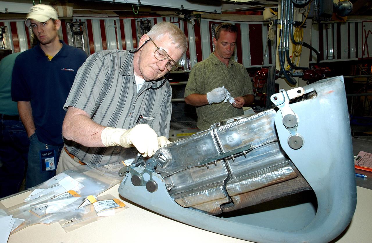
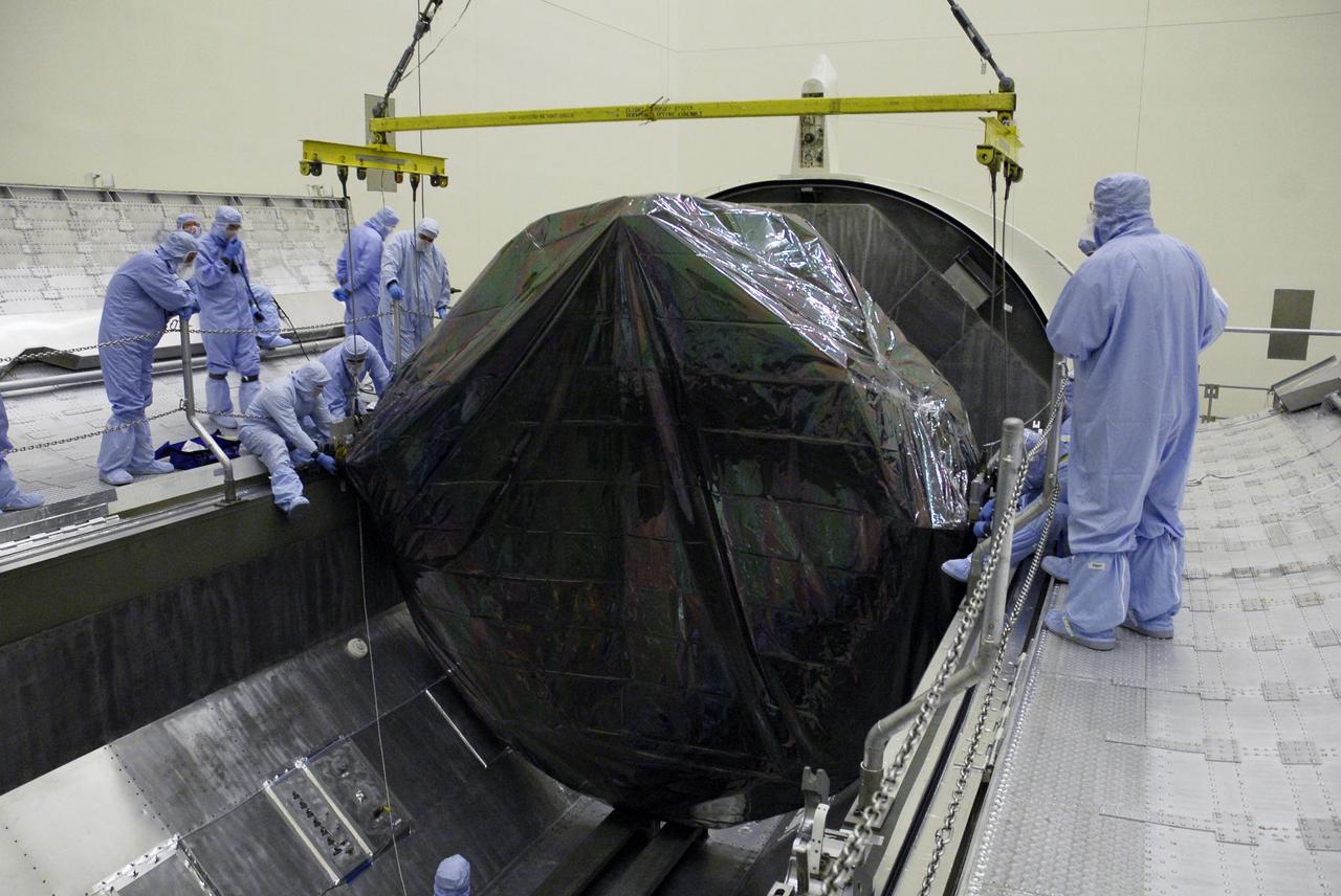
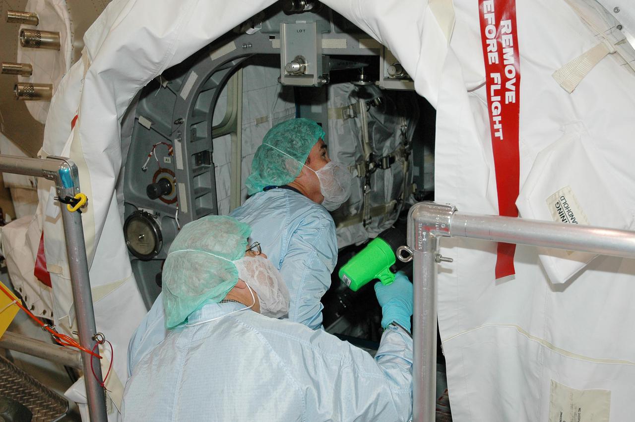
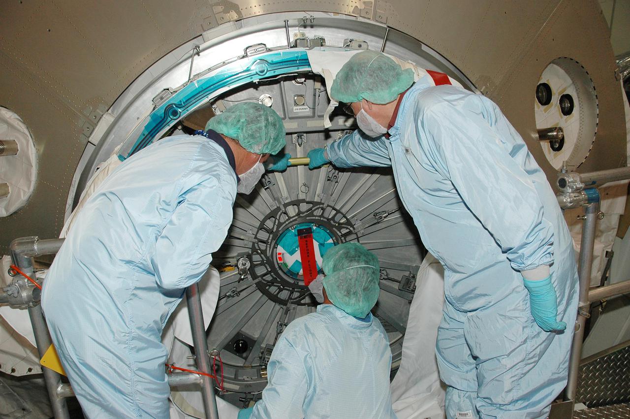
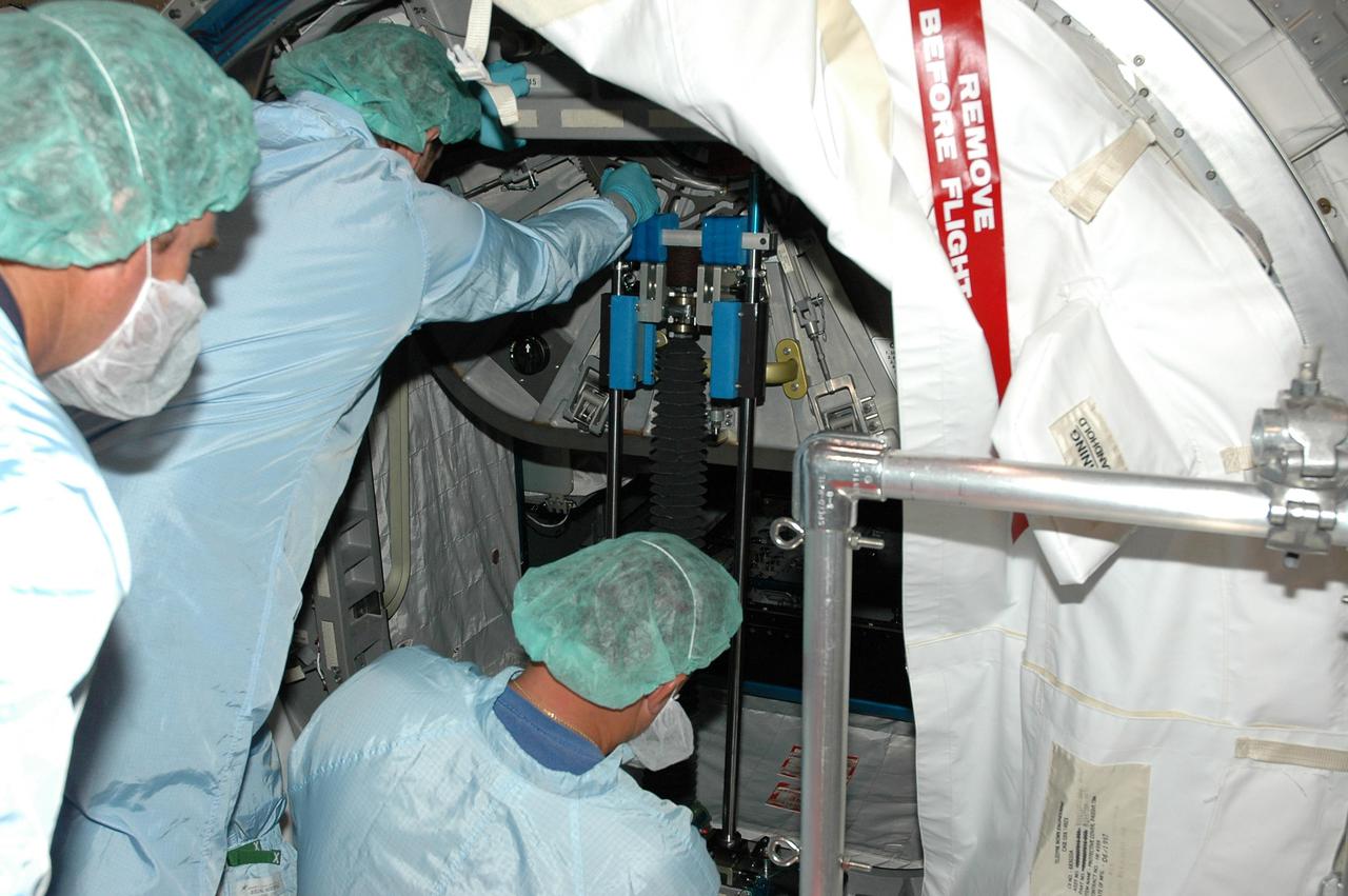
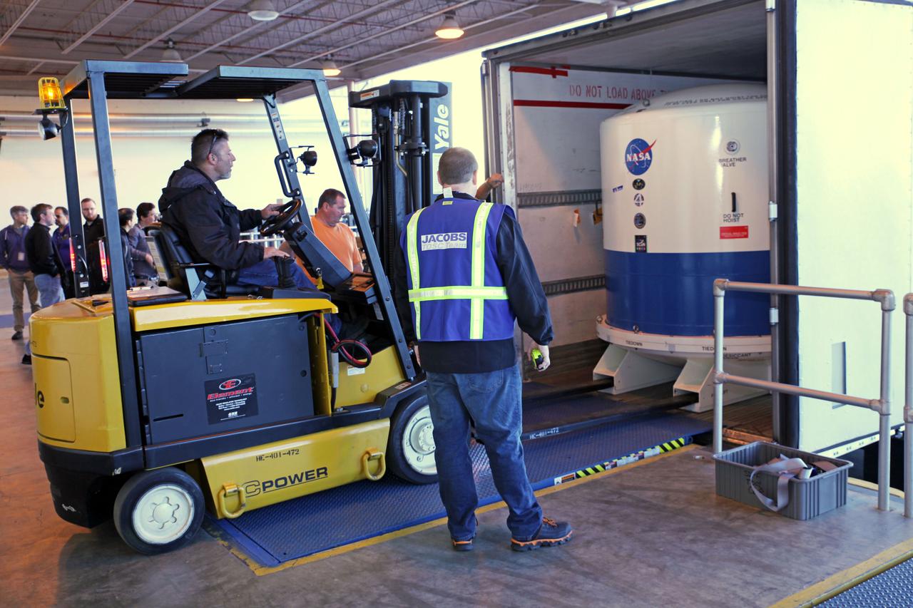
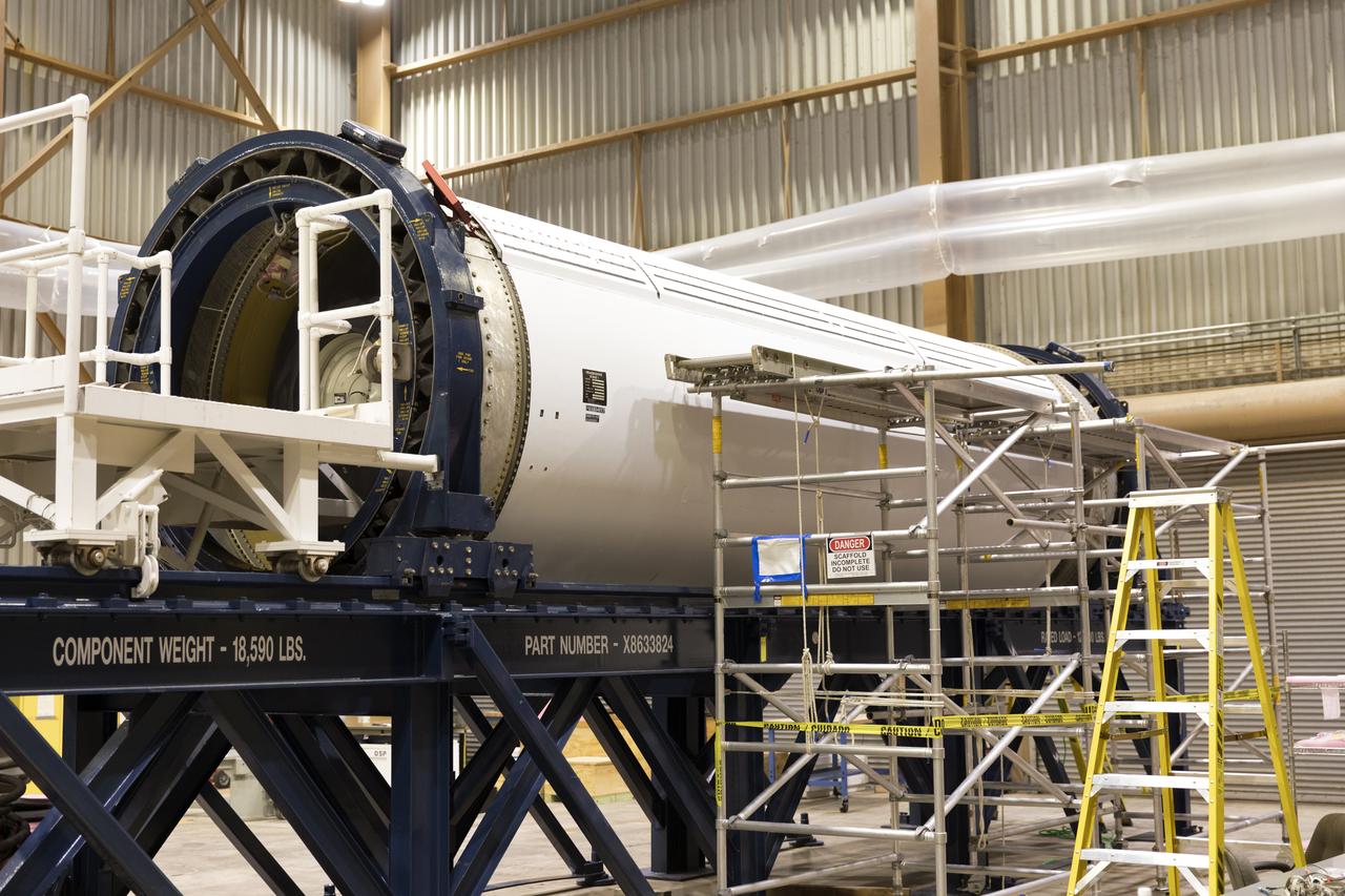
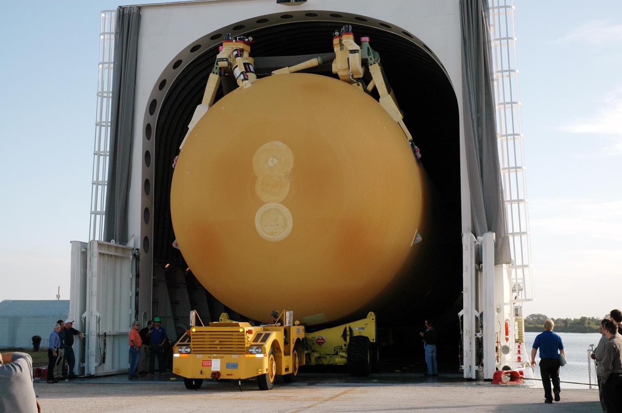
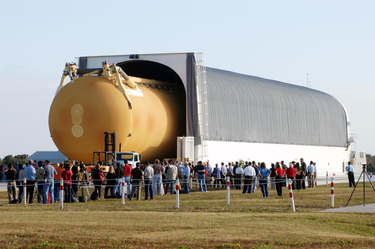
NASA Administrator Bridenstine talks with Armstrong's Larry Hudson about the capabilities of the Flight Loads Lab to conduct mechanical-load and thermal studies of structural components and complete flight vehicles.
NASA Administrator Bridenstine is inside Armstrong Flight Research Center's Flight Loads Lab, which is capable of conducting mechanical-load and thermal studies of structural components and complete flight vehicles.
This is a photo of an engineering model of the Thermal and Evolved-Gas Analyzer TEGA instrument on board NASA Phoenix Mars Lander. This view shows a TEGA oven-loading mechanism beneath the input screen.
TEGA Whirligig Model
Mechanical engineering and integration technician Ivan Pratt installs brackets onto the static load testing platform in preparation of an OSAM-1 ground support equipment proof test at Goddard Space Flight Center, Greenbelt Md., July 19, 2023. This photo has been reviewed by OSAM1 project management and the Export Control Office and is released for public view. NASA/Mike Guinto
GSFC_20230719_OSAM1_006753
KENNEDY SPACE CENTER, FLA. -  William Gaetjens (background), with the Vehicle Integration Test Team (VITT) directs Japanese astronaut Koichi Wakata’s attention to the spars installed on the wing of the orbiter Atlantis.  Reinforced Carbon Carbon (RCC) panels are mechanically attached to the wing via the spars - a series of floating joints - to reduce loading on the panels caused by wing deflections. The aluminum and the metallic attachments are protected from exceeding temperature limits by internal insulation.
KENNEDY SPACE CENTER, FLA. - William Gaetjens (background), with the Vehicle Integration Test Team (VITT) directs Japanese astronaut Koichi Wakata’s attention to the spars installed on the wing of the orbiter Atlantis. Reinforced Carbon Carbon (RCC) panels are mechanically attached to the wing via the spars - a series of floating joints - to reduce loading on the panels caused by wing deflections. The aluminum and the metallic attachments are protected from exceeding temperature limits by internal insulation.
KENNEDY SPACE CENTER, FLA. -  In the Orbiter Processing Facility, Mike Hyatt, with United Space Alliance, installs a spar on the wing of the orbiter Atlantis.  Reinforced Carbon Carbon (RCC) panels are mechanically attached to the wing with a series of floating joints - spars - to reduce loading on the panels caused by wing deflections. The aluminum and the metallic attachments are protected from exceeding temperature limits by internal insulation.
KENNEDY SPACE CENTER, FLA. - In the Orbiter Processing Facility, Mike Hyatt, with United Space Alliance, installs a spar on the wing of the orbiter Atlantis. Reinforced Carbon Carbon (RCC) panels are mechanically attached to the wing with a series of floating joints - spars - to reduce loading on the panels caused by wing deflections. The aluminum and the metallic attachments are protected from exceeding temperature limits by internal insulation.
KENNEDY SPACE CENTER, FLA. - In the Orbiter Processing Facility, John Newport, with United Space Alliance, inspects a spar to be installed on the wing of the orbiter Atlantis.  Reinforced Carbon Carbon (RCC) panels are mechanically attached to the wing with a series of floating joints - spars - to reduce loading on the panels caused by wing deflections. The aluminum and the metallic attachments are protected from exceeding temperature limits by internal insulation.
KENNEDY SPACE CENTER, FLA. - In the Orbiter Processing Facility, John Newport, with United Space Alliance, inspects a spar to be installed on the wing of the orbiter Atlantis. Reinforced Carbon Carbon (RCC) panels are mechanically attached to the wing with a series of floating joints - spars - to reduce loading on the panels caused by wing deflections. The aluminum and the metallic attachments are protected from exceeding temperature limits by internal insulation.
KENNEDY SPACE CENTER, FLA. - Japanese astronaut Koichi Wakata gestures as he examines the spar installation (behind him) on the wing of the orbiter Atlantis.  Reinforced Carbon Carbon (RCC) panels are mechanically attached to the wing via the spars - a series of floating joints - to reduce loading on the panels caused by wing deflections. The aluminum and the metallic attachments are protected from exceeding temperature limits by internal insulation.
KENNEDY SPACE CENTER, FLA. - Japanese astronaut Koichi Wakata gestures as he examines the spar installation (behind him) on the wing of the orbiter Atlantis. Reinforced Carbon Carbon (RCC) panels are mechanically attached to the wing via the spars - a series of floating joints - to reduce loading on the panels caused by wing deflections. The aluminum and the metallic attachments are protected from exceeding temperature limits by internal insulation.
KENNEDY SPACE CENTER, FLA. - In the Orbiter Processing Facility, John Newport, with United Space Alliance, inspects spar installation on the wing of the orbiter Atlantis.  Reinforced Carbon Carbon (RCC) panels are mechanically attached to the wing with a series of floating joints - spars - to reduce loading on the panels caused by wing deflections. The aluminum and the metallic attachments are protected from exceeding temperature limits by internal insulation.
KENNEDY SPACE CENTER, FLA. - In the Orbiter Processing Facility, John Newport, with United Space Alliance, inspects spar installation on the wing of the orbiter Atlantis. Reinforced Carbon Carbon (RCC) panels are mechanically attached to the wing with a series of floating joints - spars - to reduce loading on the panels caused by wing deflections. The aluminum and the metallic attachments are protected from exceeding temperature limits by internal insulation.
KENNEDY SPACE CENTER, FLA. - In the Orbiter Processing Facility, Mike Hyatt (left) and Saul Ngy (right), with United Space Alliance, finish installing a spar on the wing of the orbiter Atlantis.  Reinforced Carbon Carbon (RCC) panels are mechanically attached to the wing with a series of floating joints - spars - to reduce loading on the panels caused by wing deflections. The aluminum and the metallic attachments are protected from exceeding temperature limits by internal insulation.
KENNEDY SPACE CENTER, FLA. - In the Orbiter Processing Facility, Mike Hyatt (left) and Saul Ngy (right), with United Space Alliance, finish installing a spar on the wing of the orbiter Atlantis. Reinforced Carbon Carbon (RCC) panels are mechanically attached to the wing with a series of floating joints - spars - to reduce loading on the panels caused by wing deflections. The aluminum and the metallic attachments are protected from exceeding temperature limits by internal insulation.
KENNEDY SPACE CENTER, FLA. - In the Orbiter Processing Facility (OPF), a United Space Alliance technician examines the attachment points for the spars on the exterior of a wing of Space Shuttle Atlantis. Reinforced Carbon Carbon (RCC) panels are mechanically attached to the wing with a series of floating joints - spars - to reduce loading on the panels caused by wing deflections. The aluminum and the metallic attachments are protected from exceeding temperature limits by internal insulation.  The next launch of Atlantis will be on mission STS-114, a utilization and logistics flight to the International Space Station.
KENNEDY SPACE CENTER, FLA. - In the Orbiter Processing Facility (OPF), a United Space Alliance technician examines the attachment points for the spars on the exterior of a wing of Space Shuttle Atlantis. Reinforced Carbon Carbon (RCC) panels are mechanically attached to the wing with a series of floating joints - spars - to reduce loading on the panels caused by wing deflections. The aluminum and the metallic attachments are protected from exceeding temperature limits by internal insulation. The next launch of Atlantis will be on mission STS-114, a utilization and logistics flight to the International Space Station.
KENNEDY SPACE CENTER, FLA. - In the Orbiter Processing Facility, John Newport, with United Space Alliance, inspects a piece of equipment for spar installation on the wing of the orbiter Atlantis.  Reinforced Carbon Carbon (RCC) panels are mechanically attached to the wing with a series of floating joints - spars - to reduce loading on the panels caused by wing deflections. The aluminum and the metallic attachments are protected from exceeding temperature limits by internal insulation.
KENNEDY SPACE CENTER, FLA. - In the Orbiter Processing Facility, John Newport, with United Space Alliance, inspects a piece of equipment for spar installation on the wing of the orbiter Atlantis. Reinforced Carbon Carbon (RCC) panels are mechanically attached to the wing with a series of floating joints - spars - to reduce loading on the panels caused by wing deflections. The aluminum and the metallic attachments are protected from exceeding temperature limits by internal insulation.
KENNEDY SPACE CENTER, FLA. - In the Orbiter Processing Facility (OPF), a United Space Alliance technician examines the attachment points for the spars on the exterior of a wing of Space Shuttle Atlantis. Reinforced Carbon Carbon (RCC) panels are mechanically attached to the wing with a series of floating joints - spars - to reduce loading on the panels caused by wing deflections. The aluminum and the metallic attachments are protected from exceeding temperature limits by internal insulation.  The next launch of Atlantis will be on mission STS-114, a utilization and logistics flight to the International Space Station.
KENNEDY SPACE CENTER, FLA. - In the Orbiter Processing Facility (OPF), a United Space Alliance technician examines the attachment points for the spars on the exterior of a wing of Space Shuttle Atlantis. Reinforced Carbon Carbon (RCC) panels are mechanically attached to the wing with a series of floating joints - spars - to reduce loading on the panels caused by wing deflections. The aluminum and the metallic attachments are protected from exceeding temperature limits by internal insulation. The next launch of Atlantis will be on mission STS-114, a utilization and logistics flight to the International Space Station.
KENNEDY SPACE CENTER, FLA. -  Mike Hyatt (left) and Saul Ngy, technicians with United Space Alliance, install a spar on the wing of the orbiter Atlantis.  The Reinforced Carbon Carbon (RCC) panels are mechanically attached to the wing with a series of floating joints - spars - to reduce loading on the panels caused by wing deflections. The aluminum and the metallic attachments are protected from exceeding temperature limits by internal insulation.
KENNEDY SPACE CENTER, FLA. - Mike Hyatt (left) and Saul Ngy, technicians with United Space Alliance, install a spar on the wing of the orbiter Atlantis. The Reinforced Carbon Carbon (RCC) panels are mechanically attached to the wing with a series of floating joints - spars - to reduce loading on the panels caused by wing deflections. The aluminum and the metallic attachments are protected from exceeding temperature limits by internal insulation.
KENNEDY SPACE CENTER, FLA. - In the Orbiter Processing Facility, Mike Hyatt (above) and Saul Ngy (below), with United Space Alliance, install a spar on the wing of the orbiter Atlantis.  Reinforced Carbon Carbon (RCC) panels are mechanically attached to the wing with a series of floating joints - spars - to reduce loading on the panels caused by wing deflections. The aluminum and the metallic attachments are protected from exceeding temperature limits by internal insulation.
KENNEDY SPACE CENTER, FLA. - In the Orbiter Processing Facility, Mike Hyatt (above) and Saul Ngy (below), with United Space Alliance, install a spar on the wing of the orbiter Atlantis. Reinforced Carbon Carbon (RCC) panels are mechanically attached to the wing with a series of floating joints - spars - to reduce loading on the panels caused by wing deflections. The aluminum and the metallic attachments are protected from exceeding temperature limits by internal insulation.
KENNEDY SPACE CENTER, FLA. - Japanese astronaut Koichi Wakata looks at the spars installed on the wing of the orbiter Atlantis.  Reinforced Carbon Carbon (RCC) panels are mechanically attached to the wing via the spars - a series of floating joints - to reduce loading on the panels caused by wing deflections. The aluminum and the metallic attachments are protected from exceeding temperature limits by internal insulation.
KENNEDY SPACE CENTER, FLA. - Japanese astronaut Koichi Wakata looks at the spars installed on the wing of the orbiter Atlantis. Reinforced Carbon Carbon (RCC) panels are mechanically attached to the wing via the spars - a series of floating joints - to reduce loading on the panels caused by wing deflections. The aluminum and the metallic attachments are protected from exceeding temperature limits by internal insulation.
KENNEDY SPACE CENTER, FLA. - Technician Saul Ngy, with United Space Alliance, prepares to install a spar on the wing of the orbiter Atlantis.  The Reinforced Carbon Carbon (RCC) panels are mechanically attached to the wing with a series of floating joints - spars - to reduce loading on the panels caused by wing deflections. The aluminum and the metallic attachments are protected from exceeding temperature limits by internal insulation.
KENNEDY SPACE CENTER, FLA. - Technician Saul Ngy, with United Space Alliance, prepares to install a spar on the wing of the orbiter Atlantis. The Reinforced Carbon Carbon (RCC) panels are mechanically attached to the wing with a series of floating joints - spars - to reduce loading on the panels caused by wing deflections. The aluminum and the metallic attachments are protected from exceeding temperature limits by internal insulation.
KENNEDY SPACE CENTER, FLA. -  Mike Hyatt (left) and Saul Ngy, technicians with United Space Alliance, prepare to install a spar on the wing of the orbiter Atlantis.  The Reinforced Carbon Carbon (RCC) panels are mechanically attached to the wing with a series of floating joints - spars - to reduce loading on the panels caused by wing deflections. The aluminum and the metallic attachments are protected from exceeding temperature limits by internal insulation.
KENNEDY SPACE CENTER, FLA. - Mike Hyatt (left) and Saul Ngy, technicians with United Space Alliance, prepare to install a spar on the wing of the orbiter Atlantis. The Reinforced Carbon Carbon (RCC) panels are mechanically attached to the wing with a series of floating joints - spars - to reduce loading on the panels caused by wing deflections. The aluminum and the metallic attachments are protected from exceeding temperature limits by internal insulation.
KENNEDY SPACE CENTER, FLA. - In the Orbiter Processing Facility, John Newport, with United Space Alliance, inspects the wing of the orbiter Atlantis before installing a spar. Reinforced Carbon Carbon (RCC) panels are mechanically attached to the wing with a series of floating joints - spars - to reduce loading on the panels caused by wing deflections. The aluminum and the metallic attachments are protected from exceeding temperature limits by internal insulation.
KENNEDY SPACE CENTER, FLA. -In the Orbiter Processing Facility (OPF), a United Space Alliance technician examines the attachment points for the spars on the exterior of a wing of Space Shuttle Atlantis. Reinforced Carbon Carbon (RCC) panels are mechanically attached to the wing with a series of floating joints - spars - to reduce loading on the panels caused by wing deflections. The aluminum and the metallic attachments are protected from exceeding temperature limits by internal insulation.  The next launch of Atlantis will be on mission STS-114, a utilization and logistics flight to the International Space Station.
KENNEDY SPACE CENTER, FLA. -In the Orbiter Processing Facility (OPF), a United Space Alliance technician examines the attachment points for the spars on the exterior of a wing of Space Shuttle Atlantis. Reinforced Carbon Carbon (RCC) panels are mechanically attached to the wing with a series of floating joints - spars - to reduce loading on the panels caused by wing deflections. The aluminum and the metallic attachments are protected from exceeding temperature limits by internal insulation. The next launch of Atlantis will be on mission STS-114, a utilization and logistics flight to the International Space Station.
KENNEDY SPACE CENTER, FLA. - In the Orbiter Processing Facility (OPF), United Space Alliance technicians replace the attachment points for the spars on the interior of a wing of Space Shuttle Atlantis. Reinforced Carbon Carbon (RCC) panels are mechanically attached to the wing with a series of floating joints - spars - to reduce loading on the panels caused by wing deflections. The aluminum and the metallic attachments are protected from exceeding temperature limits by internal insulation.  The next launch of Atlantis will be on mission STS-114, a utilization and logistics flight to the International Space Station.
KENNEDY SPACE CENTER, FLA. - In the Orbiter Processing Facility (OPF), United Space Alliance technicians replace the attachment points for the spars on the interior of a wing of Space Shuttle Atlantis. Reinforced Carbon Carbon (RCC) panels are mechanically attached to the wing with a series of floating joints - spars - to reduce loading on the panels caused by wing deflections. The aluminum and the metallic attachments are protected from exceeding temperature limits by internal insulation. The next launch of Atlantis will be on mission STS-114, a utilization and logistics flight to the International Space Station.
KENNEDY SPACE CENTER, FLA. - Japanese astronaut Koichi Wakata (right) listens to William Gaetjens, with the Vehicle Integration Test Team (VITT), who is providing details about the spar installation (left) on the wing of the orbiter Atlantis.  Reinforced Carbon Carbon (RCC) panels are mechanically attached to the wing via the spars - a series of floating joints - to reduce loading on the panels caused by wing deflections. The aluminum and the metallic attachments are protected from exceeding temperature limits by internal insulation.
KENNEDY SPACE CENTER, FLA. - Japanese astronaut Koichi Wakata (right) listens to William Gaetjens, with the Vehicle Integration Test Team (VITT), who is providing details about the spar installation (left) on the wing of the orbiter Atlantis. Reinforced Carbon Carbon (RCC) panels are mechanically attached to the wing via the spars - a series of floating joints - to reduce loading on the panels caused by wing deflections. The aluminum and the metallic attachments are protected from exceeding temperature limits by internal insulation.
KENNEDY SPACE CENTER, FLA. - Japanese astronaut Koichi Wakata (front) listens to William Gaetjens, with the Vehicle Integration Test Team (VITT), who is providing details about the spar installation (left) on the wing of the orbiter Atlantis.  Reinforced Carbon Carbon (RCC) panels are mechanically attached to the wing via the spars - a series of floating joints - to reduce loading on the panels caused by wing deflections. The aluminum and the metallic attachments are protected from exceeding temperature limits by internal insulation.
KENNEDY SPACE CENTER, FLA. - Japanese astronaut Koichi Wakata (front) listens to William Gaetjens, with the Vehicle Integration Test Team (VITT), who is providing details about the spar installation (left) on the wing of the orbiter Atlantis. Reinforced Carbon Carbon (RCC) panels are mechanically attached to the wing via the spars - a series of floating joints - to reduce loading on the panels caused by wing deflections. The aluminum and the metallic attachments are protected from exceeding temperature limits by internal insulation.
DEVELOPMENT TESTING BEING CONDUCTED AT THE REQUEST OF THE MSFC DYNAMICS, LOADS, AND STRENGTH BRANCH (EV31) TO STUDY THE FAILURE BEHAVIOR OF FASTENERS SUBJECTED TO COMBINED SHEAR AND TENSION LOADING.  THE DATA FROM THIS TESTING WILL BE USED TO DEVELOP APPROPRIATE STRUCTURAL ANALYSIS METHODS AS PART OF A FASTENER STANDARDS EFFORT SPONSORED BY THE NASA ENGINEERING SAFETY CENTER (NESC).  THE TEST FIXTURE WAS DESIGNED AND FABRICATED THROUGH THE MSFC MECHANICAL FABRICATION BRANCH (ES23).  THE TESTING ORGANIZATION IS THE MSFC MATERIALS TEST BRANCH (EM10).
1001518
DEVELOPMENT TESTING BEING CONDUCTED AT THE REQUEST OF THE MSFC DYNAMICS, LOADS, AND STRENGTH BRANCH (EV31) TO STUDY THE FAILURE BEHAVIOR OF FASTENERS SUBJECTED TO COMBINED SHEAR AND TENSION LOADING.  THE DATA FROM THIS TESTING WILL BE USED TO DEVELOP APPROPRIATE STRUCTURAL ANALYSIS METHODS AS PART OF A FASTENER STANDARDS EFFORT SPONSORED BY THE NASA ENGINEERING SAFETY CENTER (NESC).  THE TEST FIXTURE WAS DESIGNED AND FABRICATED THROUGH THE MSFC MECHANICAL FABRICATION BRANCH (ES23).  THE TESTING ORGANIZATION IS THE MSFC MATERIALS TEST BRANCH (EM10).
1001521
DEVELOPMENT TESTING BEING CONDUCTED AT THE REQUEST OF THE MSFC DYNAMICS, LOADS, AND STRENGTH BRANCH (EV31) TO STUDY THE FAILURE BEHAVIOR OF FASTENERS SUBJECTED TO COMBINED SHEAR AND TENSION LOADING.  THE DATA FROM THIS TESTING WILL BE USED TO DEVELOP APPROPRIATE STRUCTURAL ANALYSIS METHODS AS PART OF A FASTENER STANDARDS EFFORT SPONSORED BY THE NASA ENGINEERING SAFETY CENTER (NESC).  THE TEST FIXTURE WAS DESIGNED AND FABRICATED THROUGH THE MSFC MECHANICAL FABRICATION BRANCH (ES23).  THE TESTING ORGANIZATION IS THE MSFC MATERIALS TEST BRANCH (EM10).
1001520
DEVELOPMENT TESTING BEING CONDUCTED AT THE REQUEST OF THE MSFC DYNAMICS, LOADS, AND STRENGTH BRANCH (EV31) TO STUDY THE FAILURE BEHAVIOR OF FASTENERS SUBJECTED TO COMBINED SHEAR AND TENSION LOADING.  THE DATA FROM THIS TESTING WILL BE USED TO DEVELOP APPROPRIATE STRUCTURAL ANALYSIS METHODS AS PART OF A FASTENER STANDARDS EFFORT SPONSORED BY THE NASA ENGINEERING SAFETY CENTER (NESC).  THE TEST FIXTURE WAS DESIGNED AND FABRICATED THROUGH THE MSFC MECHANICAL FABRICATION BRANCH (ES23).  THE TESTING ORGANIZATION IS THE MSFC MATERIALS TEST BRANCH (EM10).
1001519
Computed tomography (CT) images of resin-impregnated Mechanics of Granular Materials (MGM) specimens are assembled to provide 3-D volume renderings of density patterns formed by dislocation under the external loading stress profile applied during the experiments. Experiments flown on STS-79 and STS-89. Principal Investigator: Dr. Stein Sture
Microgravity
30 calibabor Vertical Gun Range in horizontal loading position. Dr. William Quaide and Donald Gault of Ames planetology branch used this gun range to study the formation of impact craters on the Moon. N-204A Verticle Gun is used to simulate the physics and mechanics of planetaryimpact cratering phenomena.
ARC-1965-A-33996
CAPE CANAVERAL, Fla. -  In the Payload Hazardous Servicing Facility at NASA’s Kennedy Space Center, an overhead crane lifts the Flight Support System carrier with the Soft Capture Mechanism under protective cover.  The carrier is one of four associated with the STS-125 mission to service the Hubble Space Telescope.  It will be installed in the payload canister for transfer to Launch Pad 39A.   At the pad, all the carriers will be loaded into space shuttle Atlantis’ payload bay.  Launch of Atlantis is targeted for Oct. 10. Photo credit: NASA/Cory Huston
KSC-08pd2627
CAPE CANAVERAL, Fla. -   In the Payload Hazardous Servicing Facility at NASA’s Kennedy Space Center, an overhead crane lifts the Flight Support System carrier with the Soft Capture Mechanism under protective cover.  The carrier is one of four associated with the STS-125 mission to service the Hubble Space Telescope.  It will be installed in the payload canister for transfer to Launch Pad 39A.  At the pad, all the carriers will be loaded into space shuttle Atlantis’ payload bay.  Launch of Atlantis is targeted for Oct. 10. Photo credit: NASA/Cory Huston
KSC-08pd2628
KENNEDY SPACE CENTER, FLA. -  In the Orbiter Processing Facility, United Space Alliance technician Jim Burgess (right) works on the first Reinforced Carbon-Carbon panel to be installed on the left wing leading edge on Discovery.  At left is USA technician Dave Fuller.  The RCC panels are mechanically attached to the wing with spars, a series of floating joints to reduce loading on the panels caused by wing deflections.  Discovery has been named as the orbiter to fly on the first Return to Flight mission, STS-114.
KSC-04pd0530
CAPE CANAVERAL, Fla. -  In the Payload Hazardous Servicing Facility at NASA’s Kennedy Space Center, engineers control the movement of the overhead crane lifting the Flight Support System carrier with the Soft Capture Mechanism. It will be installed in the payload canister for transfer to Launch Pad 39A.  The carrier is one of four associated with the STS-125 mission to service the Hubble Space Telescope.  At the pad, all the carriers will be loaded into space shuttle Atlantis’ payload bay.  Launch of Atlantis is targeted for Oct. 10. Photo credit: NASA/Cory Huston
KSC-08pd2630
KENNEDY SPACE CENTER, FLA. -- Technicians facilitate the transfer the STS-106 payload to Atlantis on Launch Pad 39-B using the Payload Ground Handling Mechanism (PGHM). The payload within the SPACEHAB module is shown just after being loaded in the payload bay of Atlantis. The PGHM (pronounced pigem) is located inside the Payload Changeout Room (PCR) of each shuttle launch pad Rotating Service Structure. The PGHM removes payloads from a transportation canister and installs them into the orbiter. It is essentially NASA’s largest fork-lift
KSC-00pp1163
KENNEDY SPACE CENTER, FLA. -  In the Orbiter Processing Facility, United Space Alliance technicians Jim Burgess (left) and Dave Fuller (right) prepare the first Reinforced Carbon-Carbon panel for installation on the left wing leading edge on Discovery. The RCC panels are mechanically attached to the wing with spars, a series of floating joints to reduce loading on the panels caused by wing deflections. Discovery has been named as the orbiter to fly on the first Return to Flight mission, STS-114.
KSC-04pd0528
CAPE CANAVERAL, Fla. -  In the Payload Hazardous Servicing Facility at NASA’s Kennedy Space Center,  the overhead crane lowers the Flight Support System carrier with the Soft Capture Mechanism into the payload canister.  The canister will transfer the carrier to Launch Pad 39A. The carrier is one of four associated with the STS-125 mission to service the Hubble Space Telescope.  At the pad, all the carriers will be loaded into space shuttle Atlantis’ payload bay.  Launch of Atlantis is targeted for Oct. 10. Photo credit: NASA/Cory Huston
KSC-08pd2632
KENNEDY SPACE CENTER, FLA. -  In the Orbiter Processing Facility, United Space Alliance technicians Dave Fuller (left) and Jim Burgess (right) lift the first Reinforced Carbon-Carbon panel toward the left wing leading edge of Discovery for installation. The RCC panels are mechanically attached to the wing with spars, a series of floating joints to reduce loading on the panels caused by wing deflections.  Discovery has been named as the orbiter to fly on the first Return to Flight mission, STS-114.
KSC-04pd0536
CAPE CANAVERAL, Fla. -  In the Payload Hazardous Servicing Facility at NASA’s Kennedy Space Center, an overhead crane moves the Flight Support System carrier with the Soft Capture Mechanism toward the payload canister for transfer to Launch Pad 39A. The carrier is one of four associated with the STS-125 mission to service the Hubble Space Telescope.  At the pad, all the carriers will be loaded into space shuttle Atlantis’ payload bay.  Launch of Atlantis is targeted for Oct. 10. Photo credit: NASA/Cory Huston
KSC-08pd2629
iss038e003689 (11/19/2013) --- A close-up view of the Motocard hardware. The Mechanisms of Sensory-Motor Coordination in Weightlessness (Motocard) investigation is carried out on the treadmill and involves locomotion in various modes of running and walking during various modes of operation of the treadmill. During the test, electromyography of the thigh and calf muscles, support structure response, heart rate, and treadmill load parameters (actual speed, time elapsed, distance, integrated indicators for support structure response) are recorded.
Motocard Hardware
KENNEDY SPACE CENTER, FLA. -  In the Orbiter Processing Facility, United Space Alliance technicians Jim Burgess (left)  and Dave Fuller (right) carry the first Reinforced Carbon-Carbon panel toward the left wing leading edge of Discovery for installation.  The RCC panels are mechanically attached to the wing with spars, a series of floating joints to reduce loading on the panels caused by wing deflections. Discovery has been named as the orbiter to fly on the first Return to Flight mission, STS-114.
KSC-04pd0535
CAPE CANAVERAL, Fla. -  In the Payload Hazardous Servicing Facility at NASA’s Kennedy Space Center, workers begin securing the Flight Support System carrier with the Soft Capture Mechanism in the payload canister.  The canister will transfer the carrier to Launch Pad 39A.  The carrier is one of four associated with the STS-125 mission to service the Hubble Space Telescope.  At the pad, all the carriers will be loaded into space shuttle Atlantis’ payload bay.  Launch of Atlantis is targeted for Oct. 10. Photo credit: NASA/Cory Huston
KSC-08pd2634
KENNEDY SPACE CENTER, FLA. -- The STS-106 payload within the SPACEHAB Module is shown after being loaded onto Atlantis on Launch Pad 39-B using the Payload Ground Handling Mechanism (PGHM). The PGHM (pronounced pigem) is located inside the Payload Changeout Room (PCR) of each shuttle launch pad’s Rotating Service Structure. The PGHM removes payloads from a transportation canister and installs them into the orbiter. It is essentially NASA’s largest fork-lift
KSC-00pp1164
KENNEDY SPACE CENTER, FLA. -- The STS-106 payload within the SPACEHAB Module is shown after being loaded onto Atlantis on Launch Pad 39-B using the Payload Ground Handling Mechanism (PGHM). The PGHM (pronounced pigem) is located inside the Payload Changeout Room (PCR) of each shuttle launch pad’s Rotating Service Structure. The PGHM removes payloads from a transportation canister and installs them into the orbiter. It is essentially NASA’s largest fork-lift
KSC00pp1164
KENNEDY SPACE CENTER, FLA. -  In the Orbiter Processing Facility, United Space Alliance technician Dave Fuller installs the first Reinforced Carbon-Carbon panel on the left wing leading edge of Discovery. The RCC panels are mechanically attached to the wing with spars, a series of floating joints to reduce loading on the panels caused by wing deflections.  Discovery has been named as the orbiter to fly on the first Return to Flight mission, STS-114.
KSC-04pd0538
KENNEDY SPACE CENTER, FLA. -  In the Orbiter Processing Facility, the first Reinforced Carbon-Carbon panel is ready for installation on the left wing leading edge on Discovery.  The RCC panels are mechanically attached to the wing with spars, a series of floating joints to reduce loading on the panels caused by wing deflections. Discovery has been named as the orbiter to fly on the first Return to Flight mission, STS-114.
KSC-04pd0527
KENNEDY SPACE CENTER, FLA. -  In the Orbiter Processing Facility, Danny Wyatt, NASA Quality Assurance specialist, and John Legere (right), NASA Quality Assurance specialist, examine the first Reinforced Carbon-Carbon panel to be installed on the left wing leading edge on Discovery. The RCC panels are mechanically attached to the wing with spars, a series of floating joints to reduce loading on the panels caused by wing deflections. Discovery has been named as the orbiter to fly on the first Return to Flight mission, STS-114.
KSC-04pd0532
KENNEDY SPACE CENTER, FLA. -  In the Orbiter Processing Facility, United Space Alliance technicians Dave Fuller (left) and Jim Burgess (right) lift into place the first Reinforced Carbon-Carbon panel toward the left wing leading edge of Discovery for installation. The RCC panels are mechanically attached to the wing with spars, a series of floating joints to reduce loading on the panels caused by wing deflections. Discovery has been named as the orbiter to fly on the first Return to Flight mission, STS-114.
KSC-04pd0537
KENNEDY SPACE CENTER, FLA. -  In the Orbiter Processing Facility, United Space Alliance technician Jim Burgess installs the first Reinforced Carbon-Carbon panel on the left wing leading edge of Discovery. The RCC panels are mechanically attached to the wing with spars, a series of floating joints to reduce loading on the panels caused by wing deflections. Discovery has been named as the orbiter to fly on the first Return to Flight mission, STS-114.
KSC-04pd0539
KENNEDY SPACE CENTER, FLA. -  In the Orbiter Processing Facility, United Space Alliance technicians Dave Fuller (rear) and Jim Burgess (front) continue installing the first Reinforced Carbon-Carbon panel on the left wing leading edge of Discovery. The RCC panels are mechanically attached to the wing with spars, a series of floating joints to reduce loading on the panels caused by wing deflections. Discovery has been named as the orbiter to fly on the first Return to Flight mission, STS-114.
KSC-04pd0540
KENNEDY SPACE CENTER, FLA. -  In the Orbiter Processing Facility, United Space Alliance technician Jim Burgess (right) works on the first Reinforced Carbon-Carbon panel to be installed on the left wing leading edge on Discovery.  At left is USA technician Dave Fuller.  The RCC panels are mechanically attached to the wing with spars, a series of floating joints to reduce loading on the panels caused by wing deflections. Discovery has been named as the orbiter to fly on the first Return to Flight mission, STS-114.
KSC-04pd0529
KENNEDY SPACE CENTER, FLA. -  In the Orbiter Processing Facility, the left wing leading edge on Discovery is ready for installation of the first Reinforced Carbon-Carbon panel.  The RCC panels are mechanically attached to the wing with spars, a series of floating joints to reduce loading on the panels caused by wing deflections. Discovery has been named as the orbiter to fly on the first Return to Flight mission, STS-114.
KSC-04pd0526
KENNEDY SPACE CENTER, FLA. -- Technicians facilitate the transfer the STS-106 payload to Atlantis on Launch Pad 39-B using the Payload Ground Handling Mechanism (PGHM). The payload within the SPACEHAB module is shown just after being loaded in the payload bay of Atlantis. The PGHM (pronounced pigem) is located inside the Payload Changeout Room (PCR) of each shuttle launch pad Rotating Service Structure. The PGHM removes payloads from a transportation canister and installs them into the orbiter. It is essentially NASA’s largest fork-lift
KSC00pp1163
CAPE CANAVERAL, Fla. -  In the Payload Hazardous Servicing Facility at NASA’s Kennedy Space Center, workers observe the movement of the crane holding the Flight Support System carrier with the Soft Capture Mechanism. It will be installed in the payload canister for transfer to Launch Pad 39A.  The carrier is one of four associated with the STS-125 mission to service the Hubble Space Telescope.  At the pad, all the carriers will be loaded into space shuttle Atlantis’ payload bay.  Launch of Atlantis is targeted for Oct. 10. Photo credit: NASA/Cory Huston
KSC-08pd2631
KENNEDY SPACE CENTER, FLA. -  In the Orbiter Processing Facility, John Legere, NASA Quality Assurance specialist, examines the attachment point for the first Reinforced Carbon-Carbon panel to be installed on the left wing leading edge of Discovery.  The RCC panels are mechanically attached to the wing with spars, a series of floating joints to reduce loading on the panels caused by wing deflections. Discovery has been named as the orbiter to fly on the first Return to Flight mission, STS-114.
KSC-04pd0534
KENNEDY SPACE CENTER, FLA. -  In the Orbiter Processing Facility, Danny Wyatt, NASA Quality Assurance specialist, examines the attachment point for the first Reinforced Carbon-Carbon panel to be installed on the left wing leading edge of Discovery.  The RCC panels are mechanically attached to the wing with spars, a series of floating joints to reduce loading on the panels caused by wing deflections. Discovery has been named as the orbiter to fly on the first Return to Flight mission, STS-114.
KSC-04pd0533
KENNEDY SPACE CENTER, FLA.  -   On Orbiter Atlantis in NASA’s Orbiter Processing Facility, bay 1, Charles Wassen, orbiter inspector, on steps in the open door of the main landing gear helps with boroscope inspection on the retract link assembly.  At left in the chair, Dave Rumpf, materials and processing engineer, observes results on a monitor.  At right are Jessie McEnulty (in hat), mechanisms engineer, and Tony Glass, orbiter inspector, a member of the micro inspection team. To lower the main landing gear, a mechanical linkage released by each gear actuates the doors to the open position.  The landing gear reach the full-down and extended position with 10 seconds and are locked in the down position by spring-loaded downlock bungees  Atlantis is scheduled to launch in September 2005 on the second Return to Flight mission, STS-121.
KSC-05pd-1093
Tom Clark, standing, a manager with contractor ERC, works with Quentin Jones and Emily Hadley, both mechanical engineers for the liquid oxygen system, with ERC, during a countdown demonstration event of cryogenic propellant loading April 12, 2019, inside Firing Room 2 in the Launch Control Center at NASA’s Kennedy Space Center in Florida. The practice simulation involved loading of liquid hydrogen and liquid oxygen into the Space Launch System rocket’s core and upper stages to prepare for Exploration Mission-1 (EM-1). During the tanking exercise, the team worked through surprise issues in real-time. The practice countdown events are training opportunities coordinated by EM-1 Launch Director Charlie Blackwell-Thompson with Exploration Ground Systems.
Countdown Demonstration & Cryogenic Loading
KENNEDY SPACE CENTER, FLA.  -  In the Space Station Processing Facility, workers close the hatch opening on the Multi-Purpose Logistics Module Raffaello.  Previously loaded into the Payload Canister Transporter,  Raffaello was moved back to its work stand to allow the processing team access to address concerns with mechanical fasteners inside the module that do not incorporate an adequate secondary locking feature.  The assessment and additional work was conducted to ensure that the fasteners do not disengage during ascent.  Raffaello is scheduled to launch on Discovery’s Return to Flight mission STS-114.  The launch window extends July 13 to July 31.
KSC-05pd-1254
iss045e082558 (10/28/2015) --- Roscosmos cosmonaut Oleg Kononenko, wearing a harness and electrodes, is photographed during Motocard experiment operations in the Zvezda Service Module (SM) aboard the International Space Station (ISS). The Mechanisms of Sensory-Motor Coordination in Weightlessness (Motocard) investigation is carried out on the treadmill and involves locomotion in various modes of running and walking during various modes of operation of the treadmill. During the test, electromyography of the thigh and calf muscles, support structure response, heart rate, and treadmill load parameters (actual speed, time elapsed, distance, integrated indicators for support structure response) are recorded.
Kononenko during Motocard Experiment
KENNEDY SPACE CENTER, FLA.  -  Inside the wheel well behind Atlantis’ right-hand main landing gear shown here, a replacement retract link is being installed.  A small crack was found recently on the retract link assembly. To lower the main landing gear, a mechanical linkage released by each gear actuates the doors to the open position.  The landing gear reach the full-down and extended position with 10 seconds and are locked in the down position by spring-loaded downlock bungees  Atlantis is scheduled to launch in September 2005 on the second Return to Flight mission, STS-121.
KSC-05pd-1162
KENNEDY SPACE CENTER, FLA.  -  Inside the wheel well behind Atlantis’ right-hand main landing gear, workers (left) install a new retract link (at right is a reflection). The link replaces one in which a small crack was recently found.  To lower the main landing gear, a mechanical linkage released by each gear actuates the doors to the open position.  The landing gear reach the full-down and extended position with 10 seconds and are locked in the down position by spring-loaded downlock bungees  Atlantis is scheduled to launch in September 2005 on the second Return to Flight mission, STS-121.
KSC-05pd-1164
As part of Underway Recovery Test 6 on Jan. 18, 2018, the Orion test article is pulled in by a winch line at the rear of the USS Anchorage’s well deck that brings the capsule into the ship, along with four manned LLAMAs (Line Load Attenuation Mechanism Assembly) that control the capsule’s side-to-side movement and a tending line attached to a rigid hull inflatable boat for controlling Orion’s movement behind the ship. The testing with Kennedy Space Center's NASA Recovery Team and the U.S. Navy will provide important data that is being used to improve recovery procedures and hardware ahead of Orion's next flight, Artemis I, when it splashes down in the Pacific Ocean.
Underway Recovery Test 6 (URT-6) - Day 2 Activites
KENNEDY SPACE CENTER, FLA.  -   On Orbiter Atlantis in NASA’s Orbiter Processing Facility, bay 1, Scott Minnick, lead inspector for micro inspection team, inspects the area where the retract link assembly would be installed on the right-hand main landing gear.  Last week a small crack was found on the right-hand assembly.  To lower the main landing gear, a mechanical linkage released by each gear actuates the doors to the open position.  The landing gear reach the full-down and extended position with 10 seconds and are locked in the down position by spring-loaded downlock bungees  Atlantis is scheduled to launch in September 2005 on the second Return to Flight mission, STS-121.
KSC-05pd-1092
KENNEDY SPACE CENTER, FLA.  -  In the Orbiter Processing Facility at NASA’s Kennedy Space Center, this replacement retract link will be installed on orbiter Atlantis’ right-hand main landing gear.  A small crack was found recently on the retract link assembly.  To lower the main landing gear, a mechanical linkage released by each gear actuates the doors to the open position.  The landing gear reach the full-down and extended position with 10 seconds and are locked in the down position by spring-loaded downlock bungees  Atlantis is scheduled to launch in September 2005 on the second Return to Flight mission, STS-121.
KSC-05pd-1159
KENNEDY SPACE CENTER, FLA.  -  In the Space Station Processing Facility, workers check the hatch opening on the Multi-Purpose Logistics Module Raffaello before closing the hatch.  Previously loaded into the Payload Canister Transporter,  Raffaello was moved back to its work stand to allow the processing team access to address concerns with mechanical fasteners inside the module that do not incorporate an adequate secondary locking feature.  The assessment and additional work was conducted to ensure that the fasteners do not disengage during ascent.  Raffaello is scheduled to launch on Discovery’s Return to Flight mission STS-114.  The launch window extends July 13 to July 31.
KSC-05pd-1253
As part of Underway Recovery Test 6, the Orion test article is pulled in by a winch line at the rear of the USS Anchorage’s well deck that brings the capsule into the ship, along with four manned LLAMAs (Line Load Attenuation Mechanism Assembly) that control the capsule’s side-to-side movement and a tending line attached to a rigid hull inflatable boat for controlling Orion’s movement behind the ship. The testing with Kennedy Space Center's NASA Recovery Team and the U.S. Navy will provide important data that is being used to improve recovery procedures and hardware ahead of Orion's next flight, Exploration Mission-1, when it splashes down in the Pacific Ocean.
Underway Recovery Test 6 (URT-6) - Day 2 Activites
KENNEDY SPACE CENTER, FLA.  -  In the Space Station Processing Facility, workers make a final check inside the hatch of the Multi-Purpose Logistics Module Raffaello before it is closed.  Previously loaded into the Payload Canister Transporter,  Raffaello was moved back to its work stand to allow the processing team access to address concerns with mechanical fasteners inside the module that do not incorporate an adequate secondary locking feature.  The assessment and additional work was conducted to ensure that the fasteners do not disengage during ascent.  Raffaello is scheduled to launch on Discovery’s Return to Flight mission STS-114.  The launch window extends July 13 to July 31.
KSC-05pd-1252
As part of Underway Recovery Test 6, the Orion test article is pulled in by a winch line at the rear of the USS Anchorage’s well deck that brings the capsule into the ship, along with four manned LLAMAs (Line Load Attenuation Mechanism Assembly) that control the capsule’s side-to-side movement and a tending line attached to a rigid hull inflatable boat for controlling Orion’s movement behind the ship. The testing with Kennedy Space Center's NASA Recovery Team and the U.S. Navy will provide important data that is being used to improve recovery procedures and hardware ahead of Orion's next flight, Exploration Mission-1, when it splashes down in the Pacific Ocean.
Underway Recovery Test 6 (URT-6) - Day 2 Activites
As part of Underway Recovery Test 6 on Jan. 18, 2018, the Orion test article is pulled in by a winch line at the rear of the USS Anchorage’s well deck that brings the capsule into the ship, along with four manned LLAMAs (Line Load Attenuation Mechanism Assembly) that control the capsule’s side-to-side movement and a tending line attached to a rigid hull inflatable boat for controlling Orion’s movement behind the ship. The testing with Kennedy Space Center's NASA Recovery Team and the U.S. Navy will provide important data that is being used to improve recovery procedures and hardware ahead of Orion's next flight, Artemis I, when it splashes down in the Pacific Ocean.
Underway Recovery Test 6 (URT-6) - Day 2 Activites
KENNEDY SPACE CENTER, FLA.  -  In the Orbiter Processing Facility at NASA’s Kennedy Space Center, a replacement retract link (left) is being installed because a small crack was found recently on the retract link assembly.  One end of the link is tethered until it is attached.  At right is a blurred reflection on a plastic barrier. To lower the main landing gear, a mechanical linkage released by each gear actuates the doors to the open position.  The landing gear reach the full-down and extended position with 10 seconds and are locked in the down position by spring-loaded downlock bungees  Atlantis is scheduled to launch in September 2005 on the second Return to Flight mission, STS-121.
KSC-05pd-1165
iss045e082560 (10/28/2015) --- Roscosmos cosmonaut Oleg Kononenko, wearing a harness and electrodes, is photographed during Motocard experiment operations in the Zvezda Service Module (SM) aboard the International Space Station (ISS). The Mechanisms of Sensory-Motor Coordination in Weightlessness (Motocard) investigation is carried out on the treadmill and involves locomotion in various modes of running and walking during various modes of operation of the treadmill. During the test, electromyography of the thigh and calf muscles, support structure response, heart rate, and treadmill load parameters (actual speed, time elapsed, distance, integrated indicators for support structure response) are recorded.
Kononenko during Motocard Experiment
KENNEDY SPACE CENTER, FLA.  -  In the Space Station Processing Facility, the Multi-Purpose Logistics Module Raffaello (background) sits on a work stand.  It is ready for hatch closure after recent testing. Previously loaded into the Payload Canister Transporter,  Raffaello was moved back to its work stand to allow the processing team access to address concerns with mechanical fasteners inside the module that do not incorporate an adequate secondary locking feature.  The assessment and additional work was conducted to ensure that the fasteners do not disengage during ascent.  Raffaello is scheduled to launch on Discovery’s Return to Flight mission STS-114.  The launch window extends July 13 to July 31.
KSC-05pd-1251
KENNEDY SPACE CENTER, FLA.  -  In the Orbiter Processing Facility at NASA’s Kennedy Space Center, workers prepare a replacement retract link for installation on orbiter Atlantis’ right-hand main landing gear.  A small crack was found recently on the retract link assembly. To lower the main landing gear, a mechanical linkage released by each gear actuates the doors to the open position.  The landing gear reach the full-down and extended position with 10 seconds and are locked in the down position by spring-loaded downlock bungees  Atlantis is scheduled to launch in September 2005 on the second Return to Flight mission, STS-121.
KSC-05pd-1161
CAPE CANAVERAL, Fla. -  In the Payload Hazardous Servicing Facility at NASA’s Kennedy Space Center, workers monitor the movement of the Flight Support System carrier with the Soft Capture Mechanism as it is lowered into the payload canister.  The carrier is associated with the STS-125 mission to service the Hubble Space Telescope.  The canister will transfer the carrier to Launch Pad 39A.  The carrier is one of four associated with the STS-125 mission to service the Hubble Space Telescope.  At the pad, all the carriers will be loaded into space shuttle Atlantis’ payload bay.  Launch of Atlantis is targeted for Oct. 10. Photo credit: NASA/Cory Huston
KSC-08pd2633
Off the rear of the USS Anchorage, the Orion test article is pulled in by a winch line at the rear of the USS Anchorage’s well deck that brings the capsule into the ship, along with four manned LLAMAs (Line Load Attenuation Mechanism Assembly) that control the capsule’s side-to-side movement and a tending line attached to a rigid hull inflatable boat for controlling Orion’s movement behind the ship. The Underway Recovery Test 6 (URT-6) is spearheaded by Kennedy Space Center's NASA Recovery Team. In partnership with the U.S. Navy, the testing will provide important data that is being used to improve recovery procedures and hardware ahead of Orion's next flight, Exploration Mission-1, when it splashes down in the Pacific Ocean.
Underway Recovery Test 6 (URT-6) - Day 2 Activites
iss038e003641 (11/18/2014) --- A View of Cosmonaut Sergey Ryaznskiy (lower body only), setting up the Motocard experiment in the Service Module (SM) aboard the International Space Station (ISS). The Mechanisms of Sensory-Motor Coordination in Weightlessness (Motocard) investigation is carried out on the treadmill and involves locomotion in various modes of running and walking during various modes of operation of the treadmill. During the test, electromyography of the thigh and calf muscles, support structure response, heart rate, and treadmill load parameters (actual speed, time elapsed, distance, integrated indicators for support structure response) are recorded.
Ryazanskiy sets up Motocard Experiment in the SM
KENNEDY SPACE CENTER, FLA.  -  In the Orbiter Processing Facility at NASA’s Kennedy Space Center, workers prepare a replacement retract link for installation on orbiter Atlantis’ right-hand main landing gear.  A small crack was found recently on the retract link assembly. To lower the main landing gear, a mechanical linkage released by each gear actuates the doors to the open position.  The landing gear reach the full-down and extended position with 10 seconds and are locked in the down position by spring-loaded downlock bungees  Atlantis is scheduled to launch in September 2005 on the second Return to Flight mission, STS-121.
KSC-05pd-1160
KENNEDY SPACE CENTER, FLA.  -   On Orbiter Atlantis in NASA’s Orbiter Processing Facility, bay 1, a retract link assembly (upper and lower white rods) is on the left-hand main landing gear. Last week a small crack was found on the right-hand assembly.  To lower the main landing gear, a mechanical linkage released by each gear actuates the doors to the open position.  The landing gear reach the full-down and extended position with 10 seconds and are locked in the down position by spring-loaded downlock bungees  Atlantis is scheduled to launch in September 2005 on the second Return to Flight mission, STS-121.
KSC-05pd-1090
ISS038-E-003646 (18 Nov. 2013) --- Russian cosmonaut Sergey Ryazanskiy, wearing a harness and electrodes, is photographed during Motocard experiment operations in the Zvezda Service Module (SM) aboard the International Space Station (ISS). The Mechanisms of Sensory-Motor Coordination in Weightlessness (Motocard) investigation is carried out on the treadmill and involves locomotion in various modes of running and walking during various modes of operation of the treadmill. During the test, electromyography of the thigh and calf muscles, support structure response, heart rate, and treadmill load parameters (actual speed, time elapsed, distance, integrated indicators for support structure response) are recorded.
Ryazanskiy conducts Motocard Experiment on the TVIS
KENNEDY SPACE CENTER, FLA.  -  Inside the wheel well behind Atlantis’ right-hand main landing gear, workers attaches one end of a retract link.  It replaces one in which a small crack was recently found.  To lower the main landing gear, a mechanical linkage released by each gear actuates the doors to the open position.  The landing gear reach the full-down and extended position with 10 seconds and are locked in the down position by spring-loaded downlock bungees  Atlantis is scheduled to launch in September 2005 on the second Return to Flight mission, STS-121.
KSC-05pd-1163
Engineers test the mechanical landing system for the proposed Europa Lander project at NASA's Jet Propulsion Laboratory on Sept. 15, 2022. This test, using the Europa Lander landing gear testbed, fully exercises the Europa Lander landing gear mechanism through a simulated dynamic landing.  Europa Lander is a concept for a potential future mission that would look for signs of life in the icy surface material of Jupiter's moon Europa. The moon is thought to contain a global ocean of salty water beneath its frozen crust. If life exists in that ocean, signs of its existence called biosignatures could potentially find their way to the surface. In this mission concept, a spacecraft would land on Europa and collect and study samples from about 4 inches (10 centimeters) beneath the surface, looking for signs of life.  The Europa Lander landing gear testbed was developed to test and inform the design of the landing gear for the spacecraft: It mimics the landing loads and ground interaction forces that a single flight landing gear would experience when touching down on the Europan surface. It does this by using gravity offloading to simulate the reduced gravity on Europa, and by replicating the mass and inertial properties of a flight lander as well as all the degrees of freedom that the landing gear would experience.  Video available at https://photojournal.jpl.nasa.gov/catalog/PIA26199
Testing a Landing Gear for Potential Future Landing on Europa
KENNEDY SPACE CENTER, FLA. -  In the Orbiter Processing Facility, several workers check out the first Reinforced Carbon-Carbon panel to be installed on the left wing leading edge on Discovery.  Second from right is Danny Wyatt, NASA Quality Assurance specialist; on the left is Dave Fuller, technician; behind Wyatt is John Legere, NASA Quality Assurance specialist.   The RCC panels are mechanically attached to the wing with spars, a series of floating joints to reduce loading on the panels caused by wing deflections. The T-seals between each wing leading edge panel allow for lateral motion and thermal expansion differences between the RCC and the orbiter wing.  Discovery has been named as the orbiter to fly on the first Return to Flight mission, STS-114.
KSC-04pd0531
Launch team members are seated at the Mechanisms and Ignition Over Pressure and Sound Suppression System consoles inside Firing Room 1 of the Launch Control Center at NASA’s Kennedy Space Center in Florida on Dec. 13, 2021. They are participating in a joint integrated simulation for the Artemis I launch that covered both cryogenic loading and terminal countdown portions of prelaunch activities. Members of NASA’s mission management team and launch team conducted the simulation together. The Kennedy team was certified for the Artemis I launch. During Artemis I, the agency’s Orion spacecraft will lift off from Kennedy aboard NASA’s most powerful rocket – the Space Launch System – to fly farther than any spacecraft built for humans has ever flown. Through NASA’s Artemis missions, the agency, along with commercial and international partners, will establish a sustainable human presence on the Moon to prepare for missions to Mars.
Artemis I - EGS Launch Team Simulation
NASA’s RASSOR (Regolith Advanced Surface Systems Operations Robot) manipulates simulated regolith, or lunar dust found on the Moon’s surface, to create a three-foot berm during a site preparation test inside of the Granular Mechanics and Regolith Operations Lab at the agency’s Kennedy Space Center in Florida on Tuesday, June 3, 2025. The opposing motion of the bucket drums helps RASSOR grip the surface in low-gravity environments like the Moon or Mars. With this unique capability, RASSOR can traverse the rough surface to dig, load, haul, and dump regolith that could be used in construction or broken down into hydrogen, oxygen, or water, resources critical for sustaining human presence. RASSOR represents an earlier generation technology that informed the development of NASA’s IPEx (In-Situ Resource Utilization Pilot Excavator), serving as a precursor and foundational platform for the advanced excavation systems and autonomous capabilities now being demonstrated by this Moon-mining robot.
RASSOR Excavation Testing Swamp Works
KENNEDY SPACE CENTER, FLA.  -   On Orbiter Atlantis in NASA’s Orbiter Processing Facility, bay 1, the retract link assembly on the right-hand main landing gear has been removed and will be replaced.  Performing boroscope inspection are Charles Wassen, orbiter inspector, and Scott Minnick, lead inspector for micro inspection team.  Last week a small crack was found on the right-hand assembly.  To lower the main landing gear, a mechanical linkage released by each gear actuates the doors to the open position.  The landing gear reach the full-down and extended position with 10 seconds and are locked in the down position by spring-loaded downlock bungees  Atlantis is scheduled to launch in September 2005 on the second Return to Flight mission, STS-121.
KSC-05pd-1091
Off the rear of the USS Anchorage on Jan. 18, 2018, the Orion test article is pulled in by a winch line at the rear of the USS Anchorage’s well deck that brings the capsule into the ship, along with four manned LLAMAs (Line Load Attenuation Mechanism Assembly) that control the capsule’s side-to-side movement and a tending line attached to a rigid hull inflatable boat for controlling Orion’s movement behind the ship. The Underway Recovery Test 6 (URT-6) is spearheaded by Kennedy Space Center's NASA Recovery Team. In partnership with the U.S. Navy, the testing will provide important data that is being used to improve recovery procedures and hardware ahead of Orion's next flight, Artemis I, when it splashes down in the Pacific Ocean.
Underway Recovery Test 6 (URT-6) - Day 2 Activites
Inside the Space Station Processing Facility high bay at NASA's Kennedy Space Center in Florida, the Neutron star Interior Composition Explorer, or NICER, payload is secured inside a protective container and loaded onto a truck outside the high bay. NICER will be delivered to the International Space Station aboard the SpaceX Dragon cargo carrier on the company’s 11th commercial resupply services mission to the space station. NICER will study neutron stars through soft X-ray timing. NICER will enable rotation-resolved spectroscopy of the thermal and non-thermal emissions of neutron stars in the soft X-ray band with unprecedented sensitivity, probing interior structure, the origins of dynamic phenomena and the mechanisms that underlie the most powerful cosmic particle accelerators known.
NICER Transfer (for SpaceX CRS-11)
Bill Harrison and Bud Meilander check the setup of an Apollo Contour rocket nozzle in the Propulsion Systems Laboratory at the National Aeronautics and Space Administration (NASA) Lewis Research Center. The Propulsion Systems Laboratory contained two 14-foot diameter test chambers that could simulate conditions found at very high altitudes. The facility was used in the 1960s to study complex rocket engines such as the Pratt and Whitney RL-10 and rocket components such as the Apollo Contour nozzle, seen here. Meilander oversaw the facility’s mechanics and the installation of test articles into the chambers. Harrison was head of the Supersonic Tunnels Branch in the Test Installations Division.    Researchers sought to determine the impulse value of the storable propellant mix, classify and improve the internal engine performance, and compare the results with analytical tools. A special setup was installed in the chamber that included a device to measure the thrust load and a calibration stand. Both cylindrical and conical combustion chambers were examined with the conical large area ratio nozzles. In addition, two contour nozzles were tested, one based on the Apollo Service Propulsion System and the other on the Air Force’s Titan transtage engine. Three types of injectors were investigated, including a Lewis-designed model that produced 98-percent efficiency. It was determined that combustion instability did not affect the nozzle performance. Although much valuable information was obtained during the tests, attempts to improve the engine performance were not successful.
Apollo Contour Rocket Nozzle in the Propulsion Systems Laboratory
A mechanic checks the tubing on one of the many jacks which control the nozzle section of the 10- by 10-Foot Supersonic Wind Tunnel at the National Advisory Committee for Aeronautics (NACA) Lewis Flight Propulsion Laboratory. The 10- by 10-foot tunnel, which had its official opening in May 1956, was built under the Congressional Unitary Plan Act which coordinated wind tunnel construction at the NACA, Air Force, industry, and universities. The 10- by 10 was the largest of the three NACA tunnels built under the act.      The 10- by 10 wind tunnel can be operated as a closed circuit for aerodynamic tests or as an open circuit for propulsion investigations. The 10-foot tall and 76-foot long stainless steel nozzle section just upstream from the test section can be adjusted to change the speed and composition of the air flow. Hydraulic jacks, seen in this photograph, flex the 1.37-inch thick walls of the tunnel nozzle. The size of the nozzle’s opening controls the velocity of the air through the test section.     Seven General Electric motors capable of generating 25,000 horsepower produce the Mach 2.5 and 2.5 airflows. The facility was mostly operated at night due to its large power load requirements.
Exterior of Flexible Wall at the 10- by 10-Foot Supersonic Wind Tunnel
Secured on a flatbed transporter in its shipping container, the ground test motor for Orion's Launch Abort System (LAS) arrives at the Rotation, Processing and Surge Facility (RPSF) on July 20, 2018, at NASA's Kennedy Space Center in Florida. In the RPSF the motor will be inspected and prepared for transport to Space Launch Complex 46 (SLC-46) at Cape Canaveral Air Force Station for mechanical fit testing. This inert motor will not be used for flight, but will be used to certify flight hardware assembly in preparation for a full-stress test of the LAS, called Ascent Abort-2 (AA-2) flight test, scheduled for April 2019. During the test, the booster will launch from SLC 46, carrying a fully functional LAS and a 22,000-pound Orion test vehicle to an altitude of 31,000 feet and traveling at more than 1,000 miles an hour. The test will verify the LAS can steer the crew module and astronauts aboard to safety in the event of an issue with the Space Launch System (SLS) rocket when the spacecraft is under the highest aerodynamic loads it will experience during a rapid climb into space. NASA's Orion and Exploration Ground Systems programs and their contractors from Jacob's and Northrup Grumman in conjunction with the Air Force Space and Missile Center's Launch Operations branch SMC/LEXO, are performing the pathfinding exercises and flight operations for AA-2.
Ascent Abort 2 (AA-2) Ground Test Motor Arrival
Secured on a flatbed transporter in its shipping container, the ground test motor for Orion's Launch Abort System (LAS) is moved to the Rotation, Processing and Surge Facility (RPSF) on July 20, 2018, at NASA's Kennedy Space Center in Florida. In the RPSF the motor will be inspected and prepared for transport to Space Launch Complex 46 (SLC-46) at Cape Canaveral Air Force Station for mechanical fit testing. This inert motor will not be used for flight, but will be used to certify flight hardware assembly in preparation for a full-stress test of the LAS, called Ascent Abort-2 (AA-2) flight test, scheduled for April 2019. During the test, the booster will launch from SLC 46, carrying a fully functional LAS and a 22,000-pound Orion test vehicle to an altitude of 31,000 feet and traveling at more than 1,000 miles an hour. The test will verify the LAS can steer the crew module and astronauts aboard to safety in the event of an issue with the Space Launch System (SLS) rocket when the spacecraft is under the highest aerodynamic loads it will experience during a rapid climb into space. NASA's Orion and Exploration Ground Systems programs and their contractors from Jacob's and Northrup Grumman in conjunction with the Air Force Space and Missile Center's Launch Operations branch SMC/LEXO, are performing the pathfinding exercises and flight operations for AA-2.
Ascent Abort 2 (AA-2) Ground Test Motor Arrival
KENNEDY SPACE CENTER, FLA. - Media view the newly redesigned External Tank as it is off-loaded from the barge that carried it from the Michoud Assembly Facility in New Orleans.  The tank is being transported to the Vehicle Assembly Building.  The tank arrived Jan. 5 after a 900-mile sea voyage aboard NASA’s specially designed barge, Pegasus, from the Michoud Assembly Facility in New Orleans.  In the transfer aisle of the VAB, the tank will be raised from a horizontal to a vertical position, then lifted high up into a storage cell, or “checkout cell,” where it will undergo inspections of the mechanical, electrical and thermal protection systems.  New processing activities resulting from re-design of the tank include inspection of the bipod heater and External Tank separation camera, which includes charging the camera batteries.  The tank will be then prepared for mating to the Solid Rocket Boosters.  When preparations are complete, the tank will be lifted from the checkout cell, moved across the transfer aisle and into High Bay 1, where it will be lowered and attached to the boosters, which are sitting on the Mobile Launch Platform.  The tank is designated for the Return to Flight mission, STS-114,  targeted for a launch opportunity beginning in May. The seven-member Discovery crew will fly to the International Space Station primarily to test and evaluate new procedures for flight safety, including Space Shuttle inspection and repair techniques.
KSC-05pd-0039
The ground test motor for Orion's Launch Abort System (LAS) arrives by flatbed truck in its shipping container in the transfer aisle of the Vehicle Assembly Building on July 20, 2018, at NASA's Kennedy Space Center in Florida. It will be transferred to the Rotation, Processing and Surge Facility where it will be inspected and prepared for transport to Space Launch Complex 46 (SLC-46) at Cape Canaveral Air Force Station for mechanical fit testing. This inert motor will not be used for flight, but will be used to certify flight hardware assembly in preparation for a full-stress test of the LAS, called Ascent Abort-2 (AA-2) flight test, scheduled for April 2019. During the test, the booster will launch from SLC 46, carrying a fully functional LAS and a 22,000-pound Orion test vehicle to an altitude of 31,000 feet and traveling at more than 1,000 miles an hour. The test will verify the LAS can steer the crew module and astronauts aboard to safety in the event of an issue with the Space Launch System (SLS) rocket when the spacecraft is under the highest aerodynamic loads it will experience during a rapid climb into space. NASA's Orion and Exploration Ground Systems programs and their contractors from Jacob's and Northrup Grumman in conjunction with the Air Force Space and Missile Center's Launch Operations branch SMC/LEXO, are performing the pathfinding exercises and flight operations for AA-2.
Ascent Abort 2 (AA-2) Ground Test Motor Arrival
Secured on a flatbed transporter in its shipping container, the ground test motor for Orion's Launch Abort System (LAS) will be moved from the transfer aisle of the Vehicle Assembly Building to the Rotation, Processing and Surge Facility (RPSF) on July 20, 2018, at NASA's Kennedy Space Center in Florida. In the RPSF the motor will be inspected and prepared for transport to Space Launch Complex 46 (SLC-46) at Cape Canaveral Air Force Station for mechanical fit testing. This inert motor will not be used for flight, but will be used to certify flight hardware assembly in preparation for a full-stress test of the LAS, called Ascent Abort-2 (AA-2) flight test, scheduled for April 2019. During the test, the booster will launch from SLC 46, carrying a fully functional LAS and a 22,000-pound Orion test vehicle to an altitude of 31,000 feet and traveling at more than 1,000 miles an hour. The test will verify the LAS can steer the crew module and astronauts aboard to safety in the event of an issue with the Space Launch System (SLS) rocket when the spacecraft is under the highest aerodynamic loads it will experience during a rapid climb into space. NASA's Orion and Exploration Ground Systems programs and their contractors from Jacob's and Northrup Grumman in conjunction with the Air Force Space and Missile Center's Launch Operations branch SMC/LEXO, are performing the pathfinding exercises and flight operations for AA-2.
Ascent Abort 2 (AA-2) Ground Test Motor Arrival