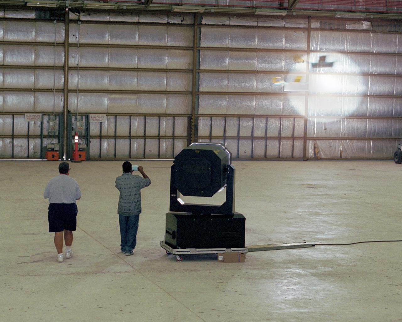
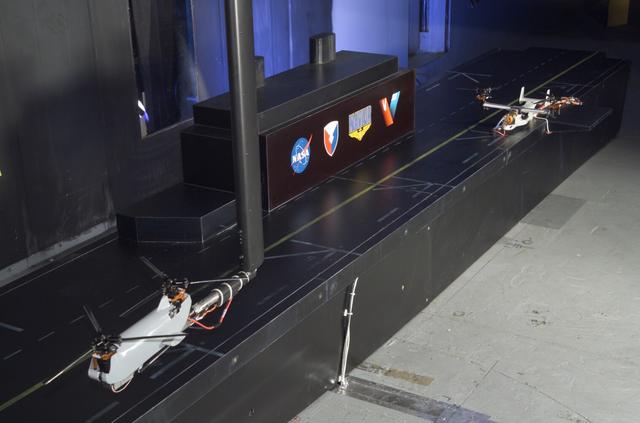
Dryden Model Shop's Tony Frakowiak remotely flies an experimental model aircraft being powered by a spotlight operated by student intern Derrick Barrett.
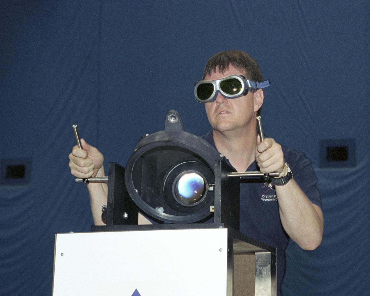
NASA Dryden project engineer Dave Bushman carefully aims the optics of a laser device at a solar cell panel on a model aircraft during the first flight demonstration of an aircraft powered by laser light.
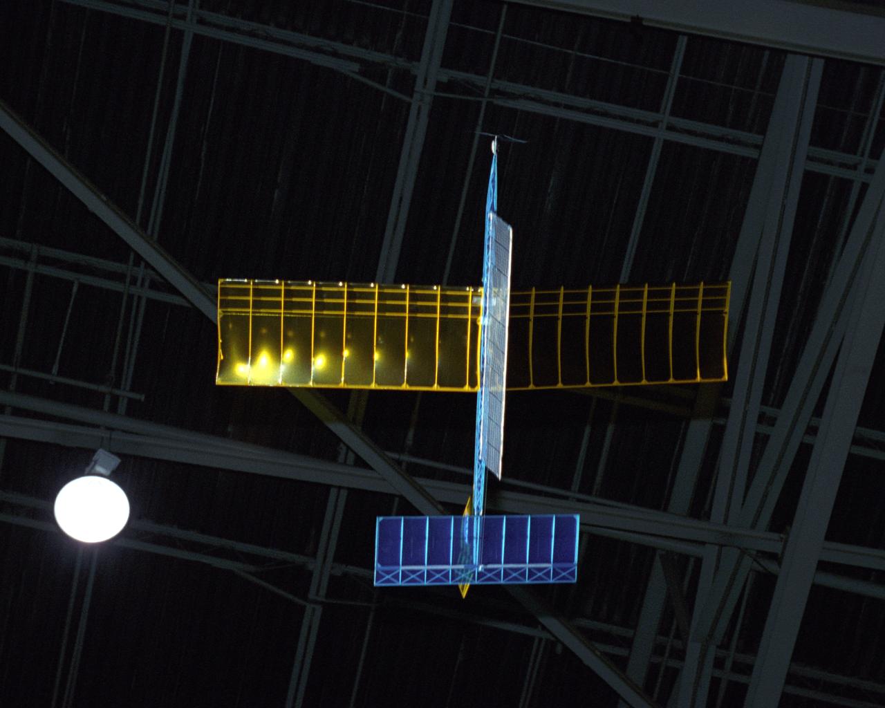
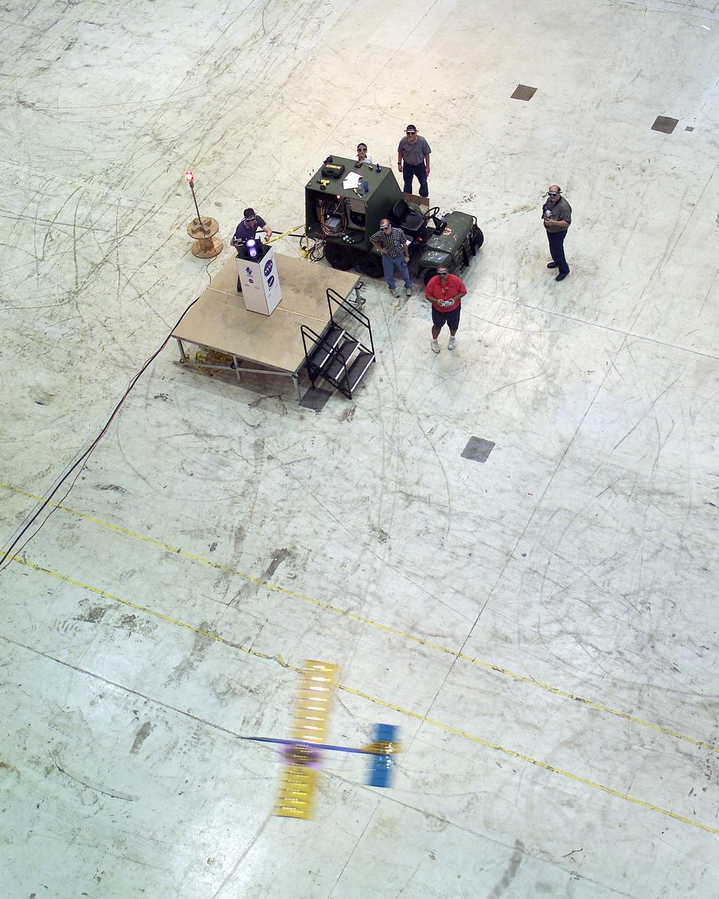
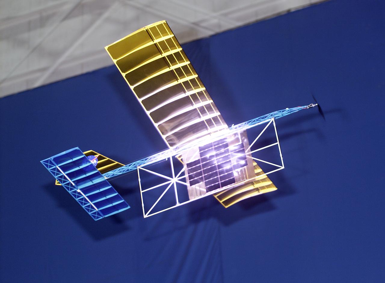
An experimental radio-controlled model aircraft is seen here in flight powered only by light energy beamed to it by a spotlight.
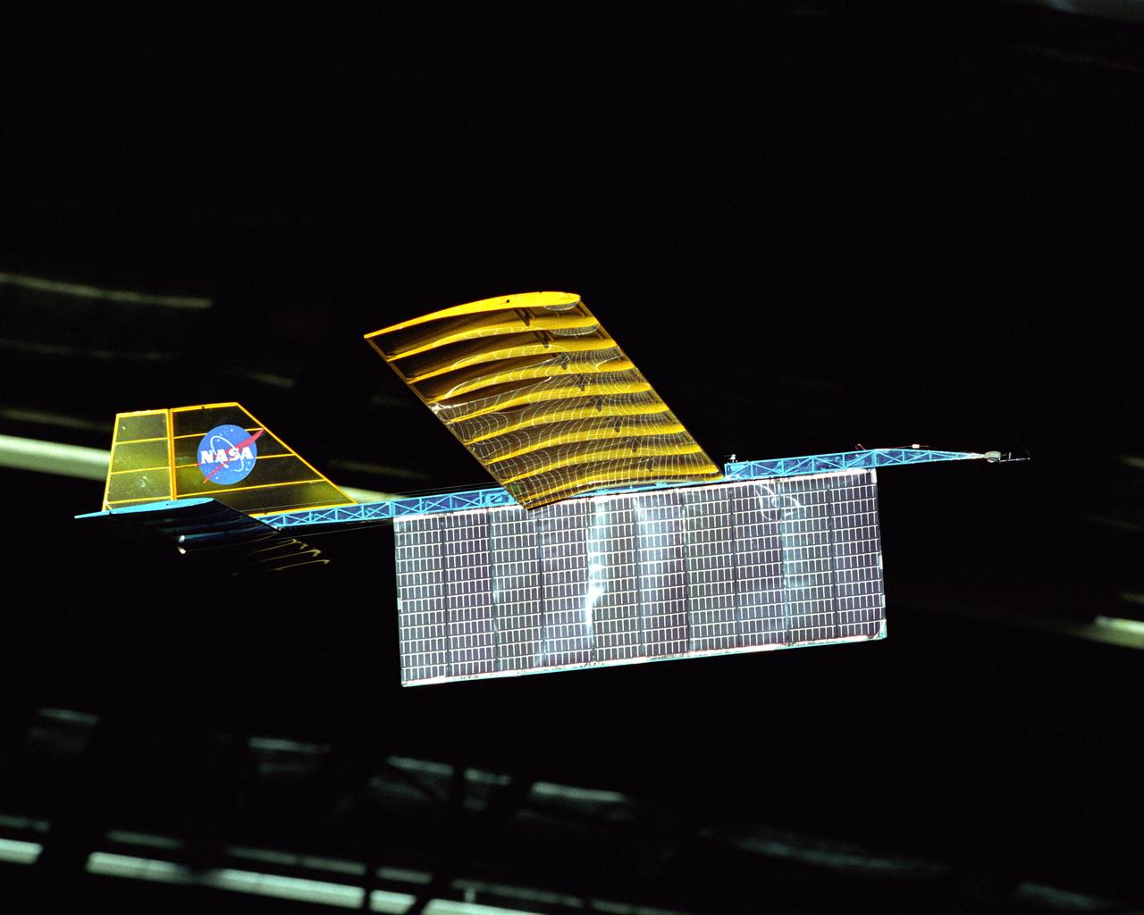
An experimental radio-controlled model aircraft is seen here in flight, powered only by light energy beamed to it by a spotlight.
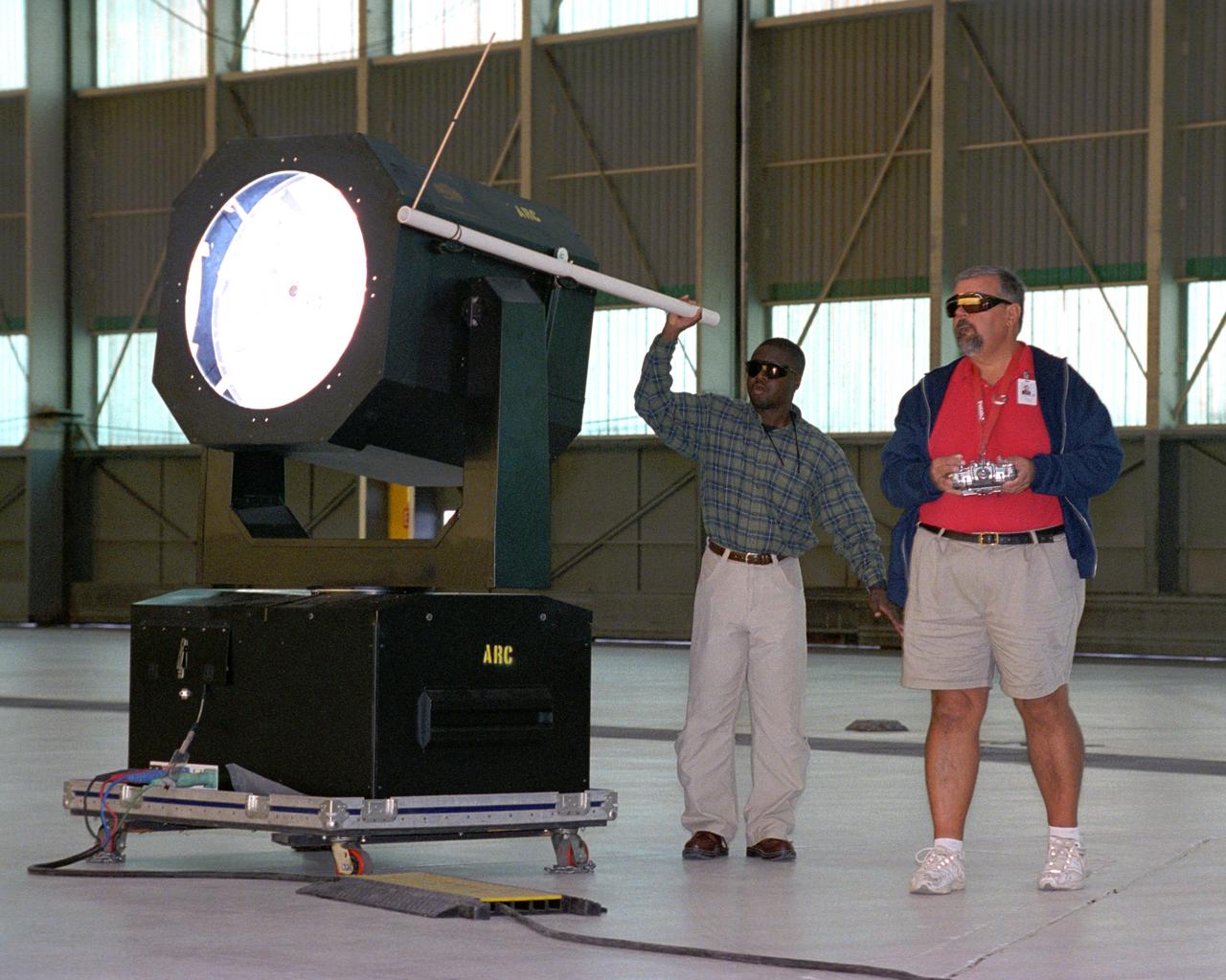
Dryden Model Shop's Tony Frakowiak remotely flies an experimental model aircraft being powered by a spotlight operated by Dryden aerospace engineer (code RA) Ryan Warner.

An experimental radio-controlled model aircraft is seen here in flight powered only by light energy beamed to it by a spotlight.
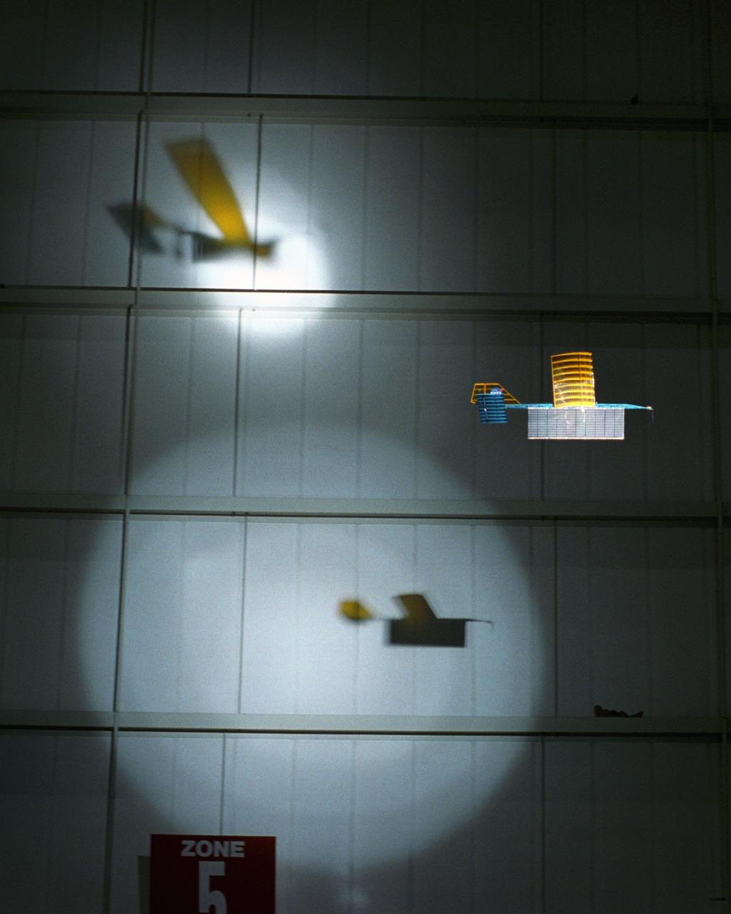
An experimental radio-controlled model aircraft casts two unique shadows as it flies inside a Dryden hangar using two spotlights as energy sources. This phase of testing was used to develop procedures and operations for "handing off" the aircraft between different sources of power.
Powered by a laser beam directed at it from a center pedestal, a lightweight model plane makes the first flight of an aircraft powered by laser energy inside a building at NASA's Marshall Space Flight Center.
With a laser beam centered on its panel of photovoltaic cells, a lightweight model plane makes the first flight of an aircraft powered by a laser beam inside a building at NASA Marshall Space Flight Center.
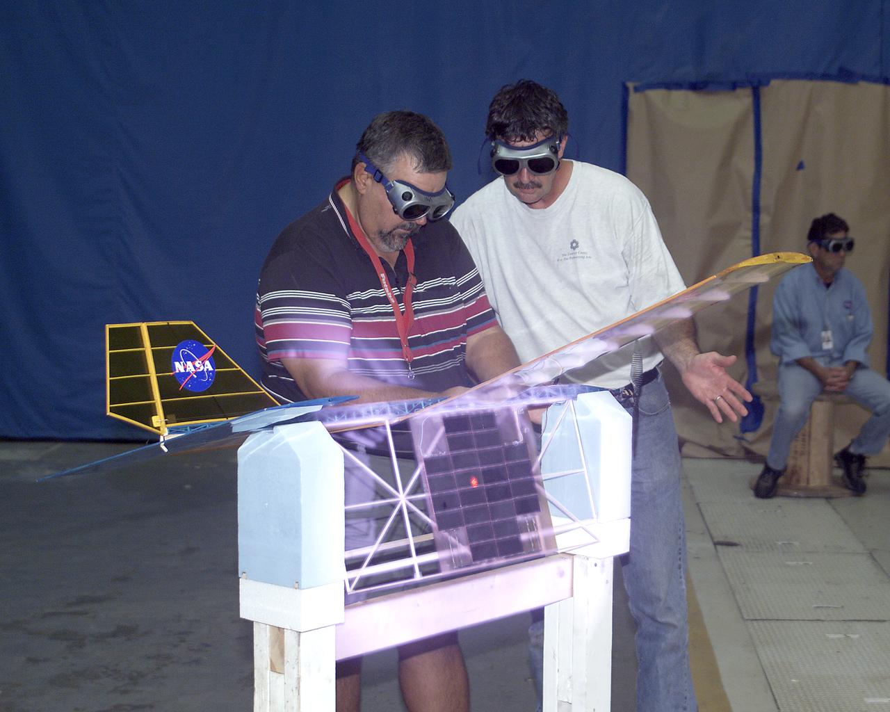
With a laser beam centered on its solar panel, a lightweight model aircraft is checked out by technician Tony Frakowiak and researcher Tim Blackwell before its power-beamed demonstration flight.
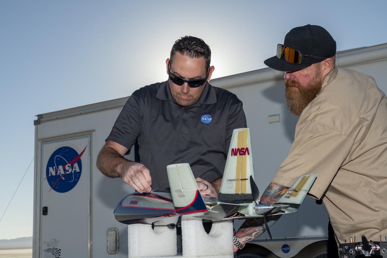
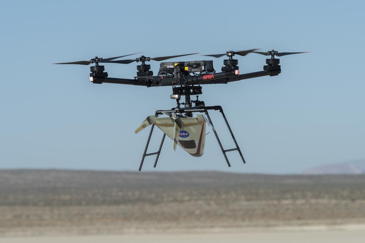
Justin Link, left, small unmanned aircraft systems pilot, and Justin Hall, chief pilot of small unmanned aircraft systems, prepare an atmospheric probe model for flight on Oct. 22, 2024. A quad rotor remotely piloted aircraft released the probe above Rogers Dry Lake, a flight area adjacent NASA’s Armstrong Flight Research Center in Edwards, California. The probe was designed and built at the center.
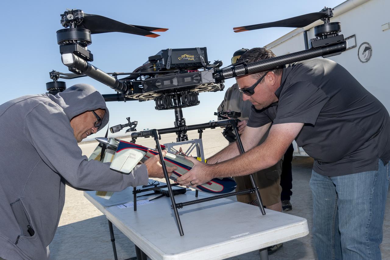
Derek Abramson, left, chief engineer for the Dale Reed Subscale Flight Research Laboratory, and Justin Link, small unmanned aircraft systems pilot, prepare an atmospheric probe model for flight on Oct. 22, 2024. A quad rotor remotely piloted aircraft released the probe above Rogers Dry Lake, a flight area adjacent to NASA’s Armstrong Flight Research Center in Edwards, California. The probe was designed and built at the center.
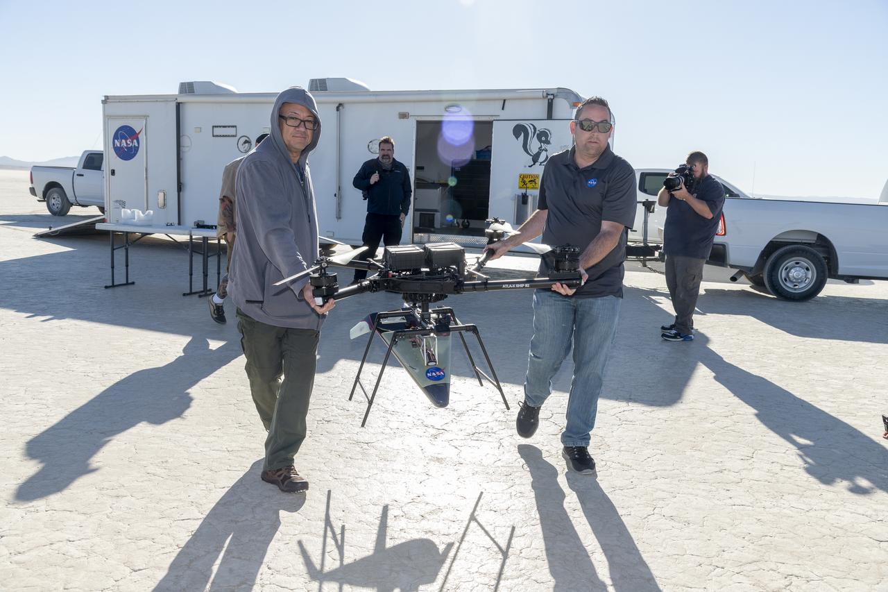
Derek Abramson, left, chief engineer for the Dale Reed Subscale Flight Research Laboratory, and Justin Link, small unmanned aircraft system pilot, carry the atmospheric probe model and a quad rotor remotely piloted aircraft to position it for flight on Oct. 24, 2024. John Bodylski, probe principal investigator, right, and videographer Jacob Shaw watch the preparations. Once at altitude, the quad rotor aircraft released the probe above Rogers Dry Lake, a flight area adjacent to NASA’s Armstrong Flight Research Center in Edwards, California. The probe was designed and built at the center.

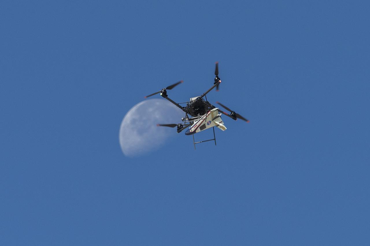
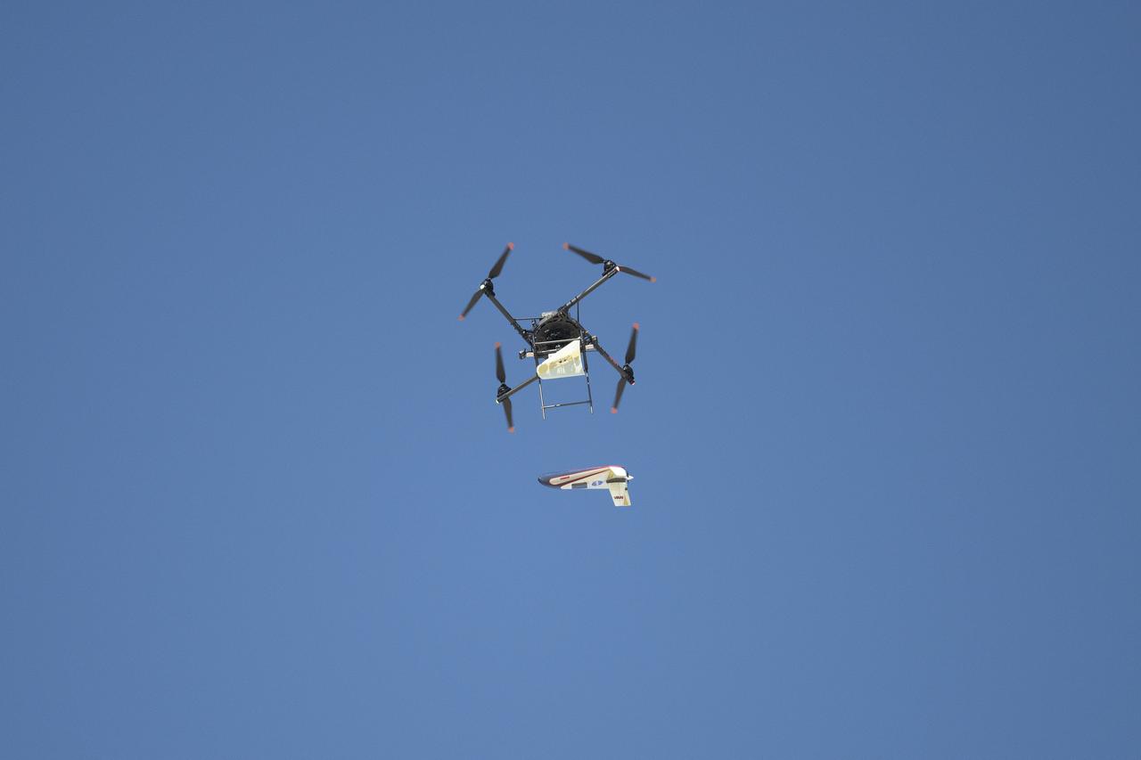
An atmospheric probe model attached upside down to a quad rotor remotely piloted aircraft ascends with the Moon visible on Oct. 22, 2024. The quad rotor aircraft released the probe above Rogers Dry Lake, a flight area adjacent NASA’s Armstrong Flight Research Center in Edwards, California. The probe was designed and built at the center.
An atmospheric probe model attached upside down to a quad rotor remotely piloted aircraft ascends with the Moon visible on Oct. 22, 2024. The quad rotor aircraft released the probe above Rogers Dry Lake, a flight area adjacent NASA’s Armstrong Flight Research Center in Edwards, California. The probe was designed and built at the center.
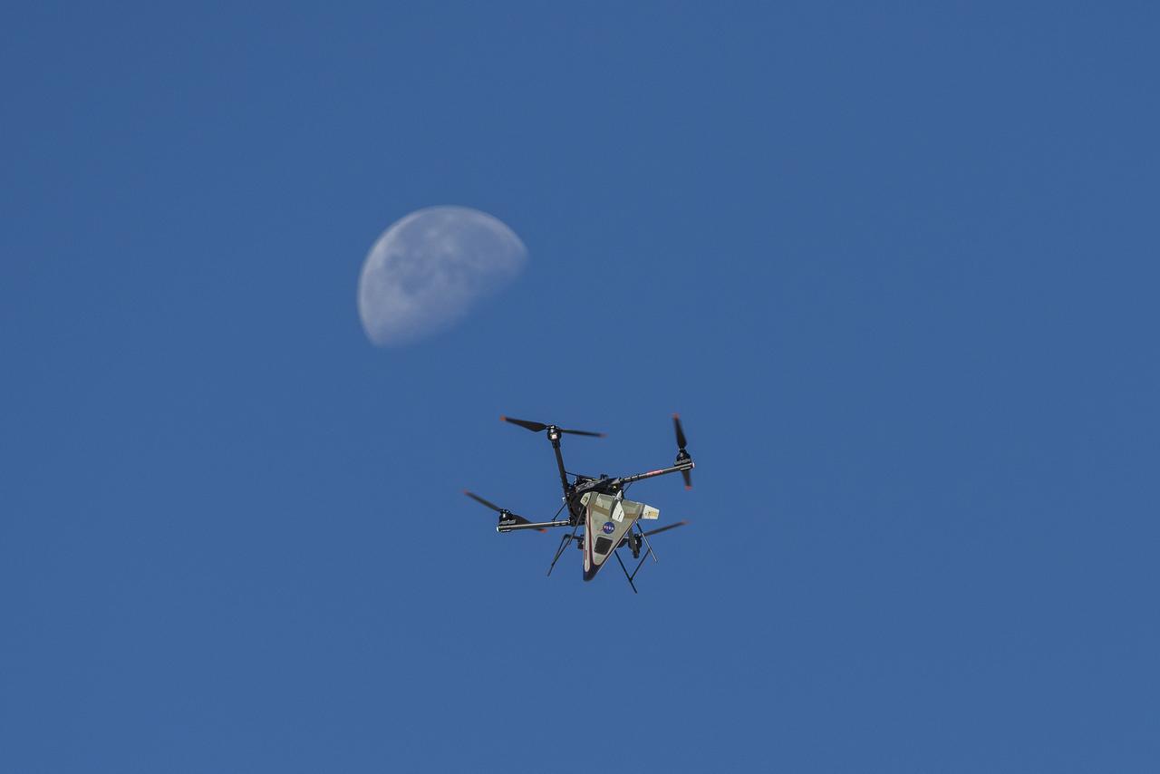
An atmospheric probe model attached upside down to a quad rotor remotely piloted aircraft ascends with the Moon visible on Oct. 22, 2024. The quad rotor aircraft released the probe above Rogers Dry Lake, a flight area adjacent NASA’s Armstrong Flight Research Center in Edwards, California. The probe was designed and built at the center.
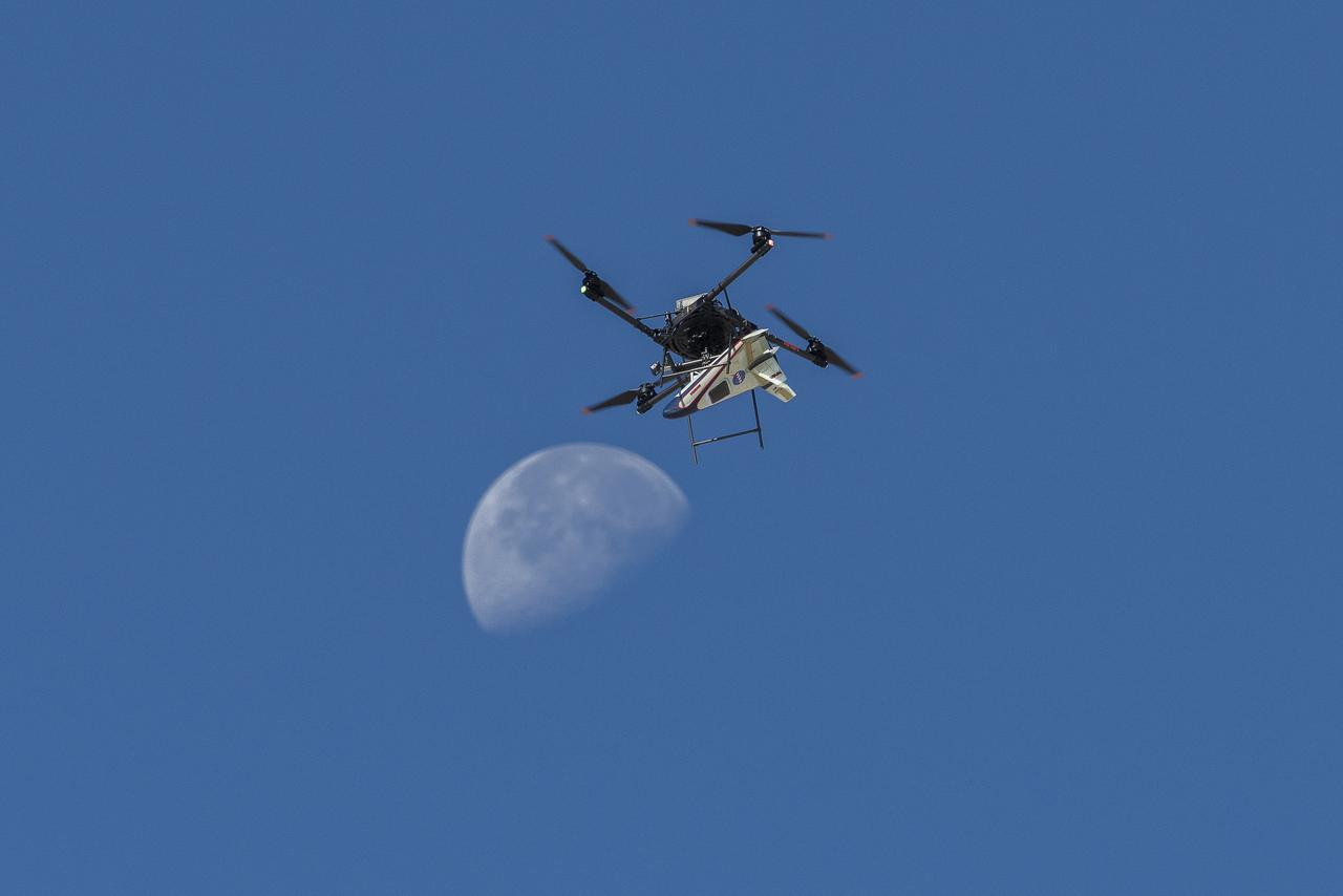
An atmospheric probe model attached upside down to a quad rotor remotely piloted aircraft ascends with the Moon visible on Oct. 22, 2024. The quad rotor aircraft released the probe above Rogers Dry Lake, a flight area adjacent NASA’s Armstrong Flight Research Center in Edwards, California. The probe was designed and built at the center.

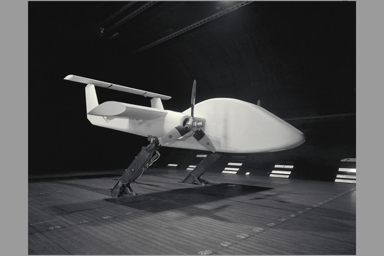
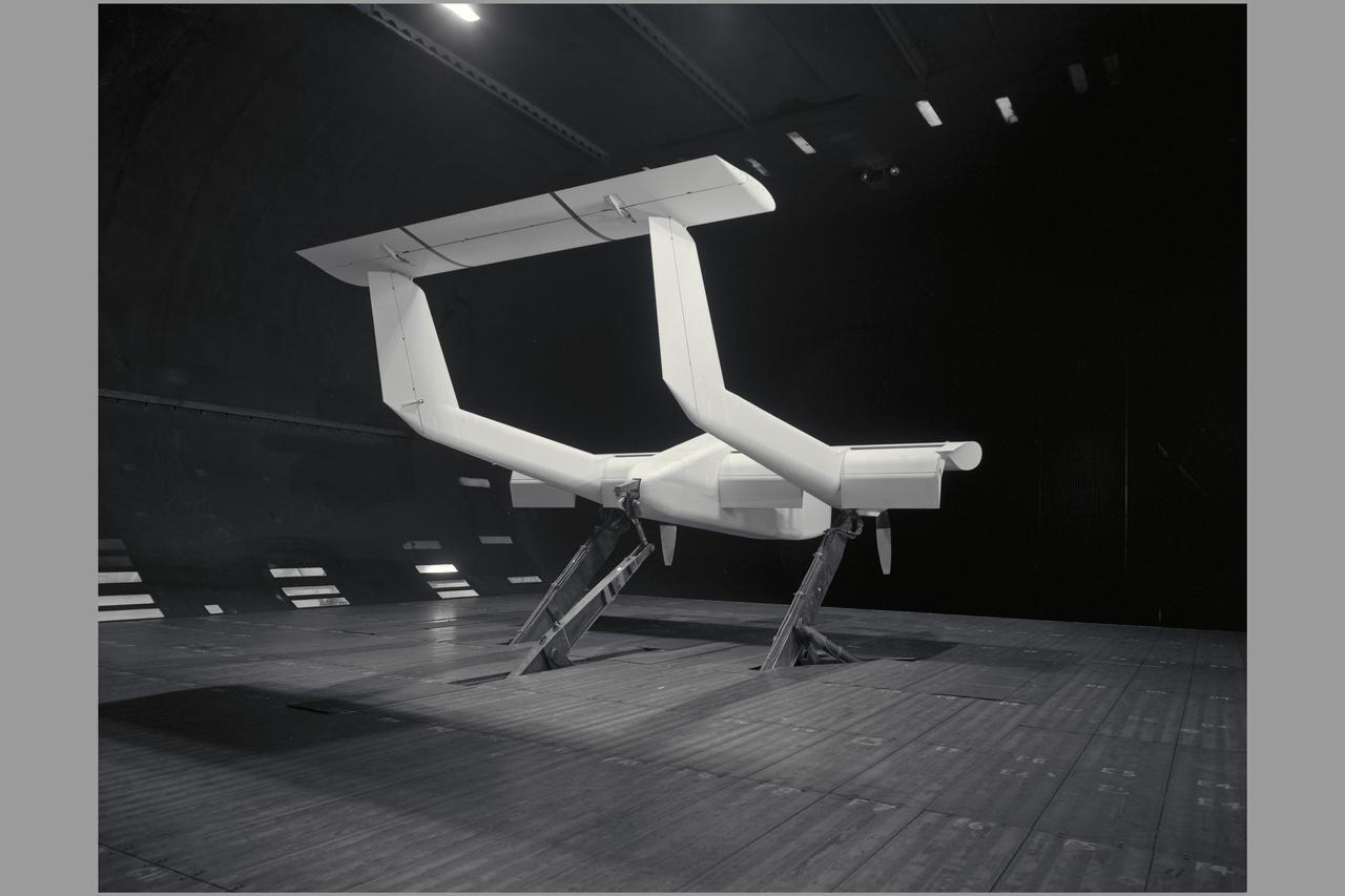
National Aeronautics and Space Administration (NASA) researcher John Carpenter inspects an aircraft model with a four-fan thrust reverser which would be studied in the 9- by 15-Foot Low Speed Wind Tunnel at the Lewis Research Center. Thrust reversers were introduced in the 1950s as a means for slowing high-speed jet aircraft during landing. Engineers sought to apply the technology to Vertical and Short Takeoff and Landing (VSTOL) aircraft in the 1970s. The new designs would have to take into account shorter landing areas, noise levels, and decreased thrust levels. A balance was needed between the thrust reverser’s efficiency, its noise generation, and the engine’s power setting. This model underwent a series of four tests in the 9- by 15-foot tunnel during April and May 1974. The model, with a high-wing configuration and no tail, was equipped with four thrust-reverser engines. The investigations included static internal aerodynamic tests on a single fan/reverser, wind tunnel isolated fan/reverser thrust tests, installation effects on a four-fan airplane model in a wind tunnel, and single reverser acoustic tests. The 9-by 15 was built inside the return leg of the 8- by 6-Foot Supersonic Wind Tunnel in 1968. The facility generates airspeeds from 0 to 175 miles per hour to evaluate the aerodynamic performance and acoustic characteristics of nozzles, inlets, and propellers, and investigate hot gas re-ingestion of advanced VSTOL concepts. John Carpenter was a technician in the Wind Tunnels Service Section of the Test Installations Division.
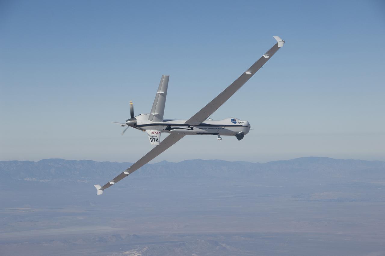
The Ikhana aircraft is flying a TAMDAR Edge probe that could significantly improve weather models and forecasts.
A quad rotor remotely piloted aircraft releases the atmospheric probe model above Rogers Dry Lake, a flight area adjacent NASA’s Armstrong Flight Research Center in Edwards, California, on Oct. 22, 2024. The probe was designed and built at the center.
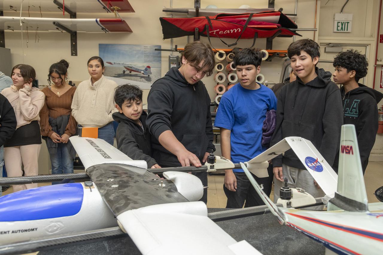
A group of middle school students engage with a model aircraft while learning from NASA experts in the model lab at NASA’s Armstrong Flight Research Center in Edwards, California during an event hosted by NASA’s California Office of STEM Engagement.
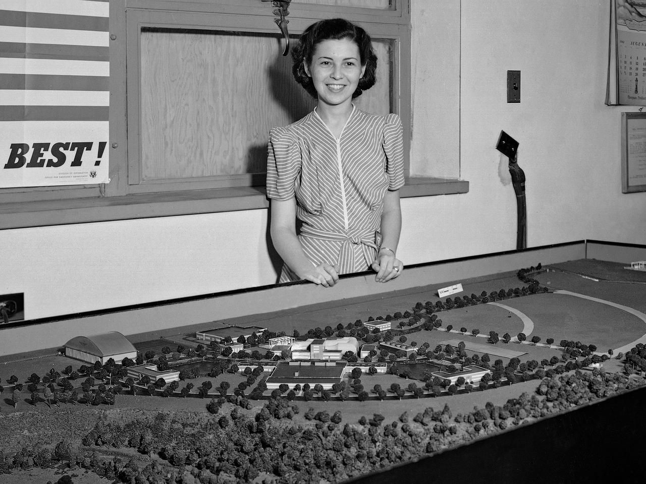
Zella Morewitz poses with a model of the National Advisory Committee for Aeronautics (NACA) Aircraft Engine Research Laboratory, currently the NASA Glenn Research Center. The model was displayed in the Administration Building during the construction of the laboratory in the early 1940s. Detailed models of the individual test facilities were also fabricated and displayed in the facilities. The laboratory was built on a wedge of land between the Cleveland Municipal Airport on the far side and the deep curving valley etched by the Rocky River on the near end. Roughly only a third of the laboratory's semicircle footprint was initially utilized. Additional facilities were added to the remaining areas in the years after World War II. In the late 1950s the site was supplemented by the acquisition of additional adjacent land. Morewitz joined the NACA in 1935 as a secretary in the main office at the Langley Memorial Aeronautical Laboratory. In September 1940 she took on the task of setting up and guiding an office dedicated to the design of the NACA’s new engine research laboratory. Morewitz and the others in the design office transferred to Cleveland in December 1941 to expedite the construction. Morewitz served as Manager Ray Sharp’s secretary for six years and was a popular figure at the new laboratory. In December 1947 Morewitz announced her engagement to Langley researcher Sidney Batterson and moved back to Virginia.
An atmospheric probe model attached upside down to a host quad rotor remotely piloted aircraft lifts off on Oct. 22, 2024. The quad rotor aircraft released the probe above Rogers Dry Lake, a flight area adjacent NASA’s Armstrong Flight Research Center in Edwards, California. The probe was designed and built at the center.
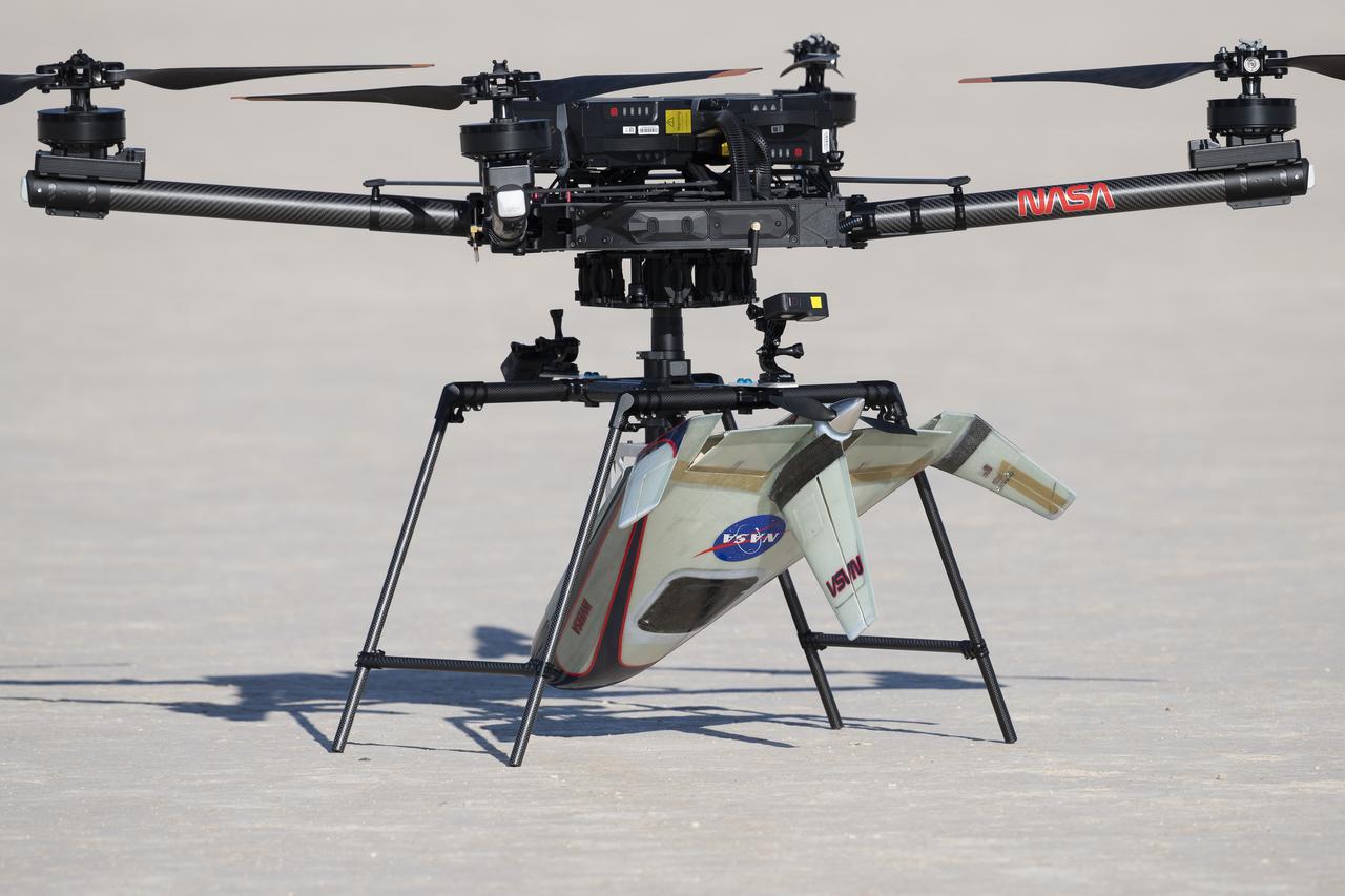
An atmospheric probe model is attached upside down to a quad rotor remotely piloted aircraft on Oct. 22, 2024. The quad rotor aircraft released the probe above Rogers Dry Lake, a flight area adjacent NASA’s Armstrong Flight Research Center in Edwards, California. The probe was designed and built at the center.
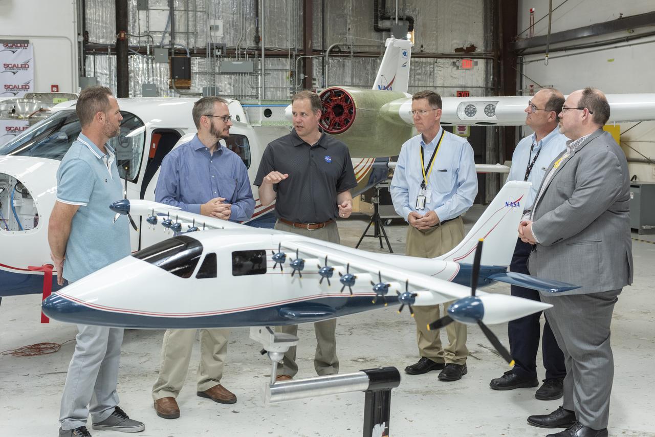
Administrator Bridenstine hears about the progress to modify the Tecnam P2006T from a combustion aircraft to an all-electric aircraft. Armstrong's X-57 team and ESAero, the prime contractor for the plane, are doing the briefing. The final configuration model of X-57 stands in front of group.
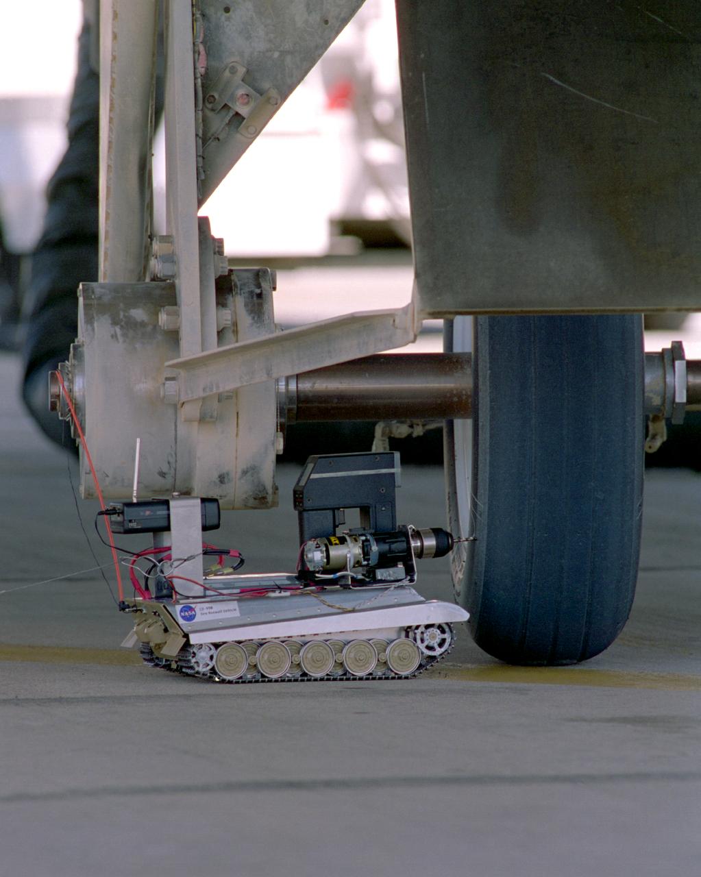
Created from a 1/16th model of a German World War II tank, the TAV (Tire Assault Vehicle) was an important safety feature for the Convair 990 Landing System Research Aircraft, which tested space shuttle tires. It was imperative to know the extreme conditions the shuttle tires could tolerate at landing without putting the shuttle and its crew at risk. In addition, the CV990 was able to land repeatedly to test the tires. The TAV was built from a kit and modified into a radio controlled, video-equipped machine to drill holes in aircraft test tires that were in imminent danger of exploding because of one or more conditions: high air pressure, high temperatures, and cord wear. An exploding test tire releases energy equivalent to two and one-half sticks of dynamite and can cause severe injuries to anyone within 50 ft. of the explosion, as well as ear injury - possibly permanent hearing loss - to anyone within 100 ft. The degree of danger is also determined by the temperature pressure and cord wear of a test tire. The TAV was developed by David Carrott, a PRC employee under contract to NASA.
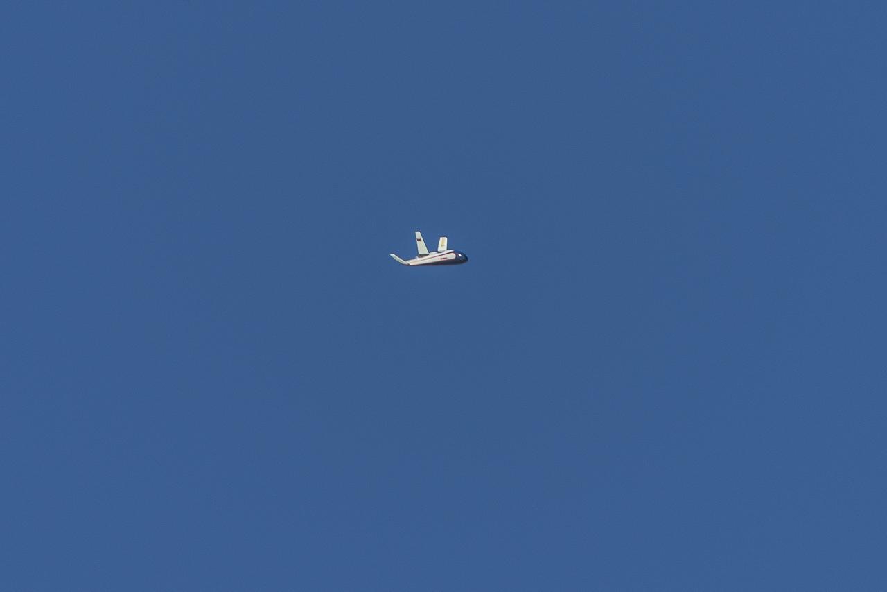
The atmospheric probe model flies free after release from a quad rotor remotely piloted aircraft above Rogers Dry Lake, a flight area adjacent NASA’s Armstrong Flight Research Center in Edwards, California, on Oct. 22, 2024. The probe was designed and built at the center.
The atmospheric probe model flies free after release from a quad rotor remotely piloted aircraft above Rogers Dry Lake, a flight area adjacent NASA’s Armstrong Flight Research Center in Edwards, California, on Oct. 22, 2024. The probe was designed and built at the center.
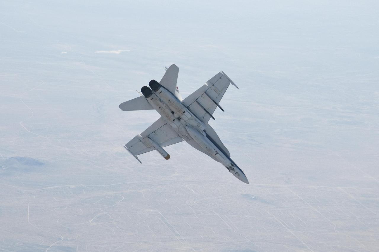
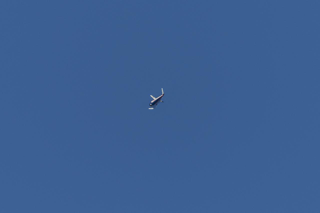
A NASA Dryden Flight Research Center F/A-18 852 aircraft performs a roll during June 2011 flight tests of a Mars landing radar. A test model of the landing radar for NASA Mars Science Laboratory mission is inside a pod under the aircraft left wing.

Photographed on 06/20/79. -- NASA airframe crash test #17. Model aircraft suspended at crash facility. Model aircraft shown on fire. Shown before and after crash.
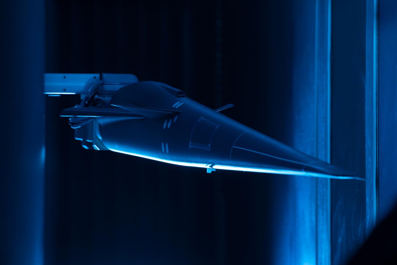
Event: Forebody and Nose - Windtunnel Testing A model of the X-59 forebody is shown in the Lockheed Martin Skunk Works’ wind tunnel in Palmdale, California. These tests gave the team measurements of wind flow angle around the aircraft’s nose and confirmed computer predictions made using computational fluid dynamics (CFD) software tools. The data will be fed into the aircraft flight control system to tell the pilot the aircraft’s altitude, speed and angle. This is part of NASA’s Quesst mission which plans to help enable supersonic air travel over land.
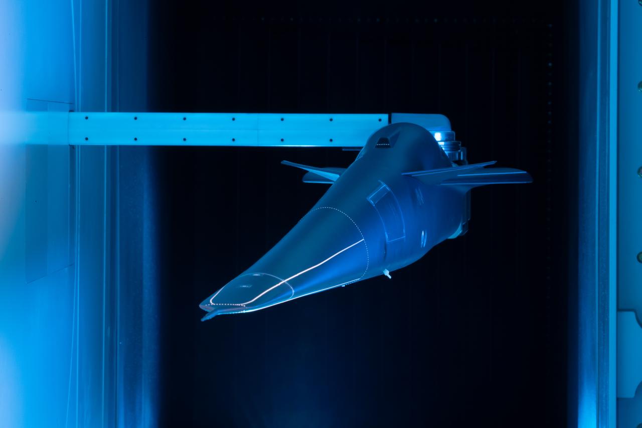
Event: Forebody and Nose - Windtunnel Testing A model of the X-59 forebody is shown in the Lockheed Martin Skunk Works’ wind tunnel in Palmdale, California. These tests gave the team measurements of wind flow angle around the aircraft’s nose and confirmed computer predictions made using computational fluid dynamics (CFD) software tools. The data will be fed into the aircraft flight control system to tell the pilot the aircraft’s altitude, speed and angle. This is part of NASA’s Quesst mission which plans to help enable supersonic air travel over land.

Wings for large scale model aircraft.
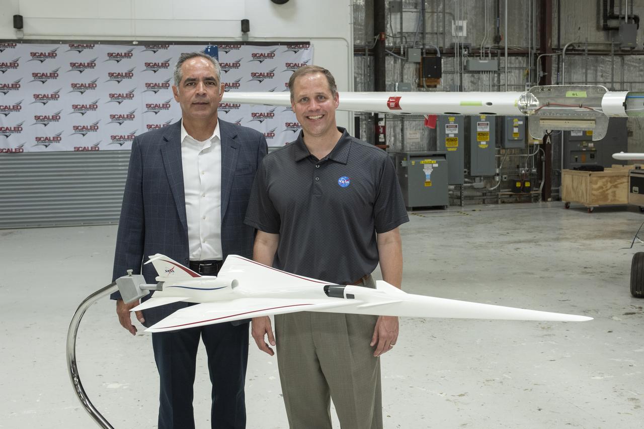
NASA Administrator Bridenstine stands with AFRC center director McBride by model NASA's Supersonic X-Plane, X-59 Quiet Supersonic Technology or QueSST. Bridenstine spoke at press event at Mojave Air and Space Port in California. The goal of X-59 is to quiet the sound when aircraft pierce the speed of sound and make a loud sonic boom on the ground.
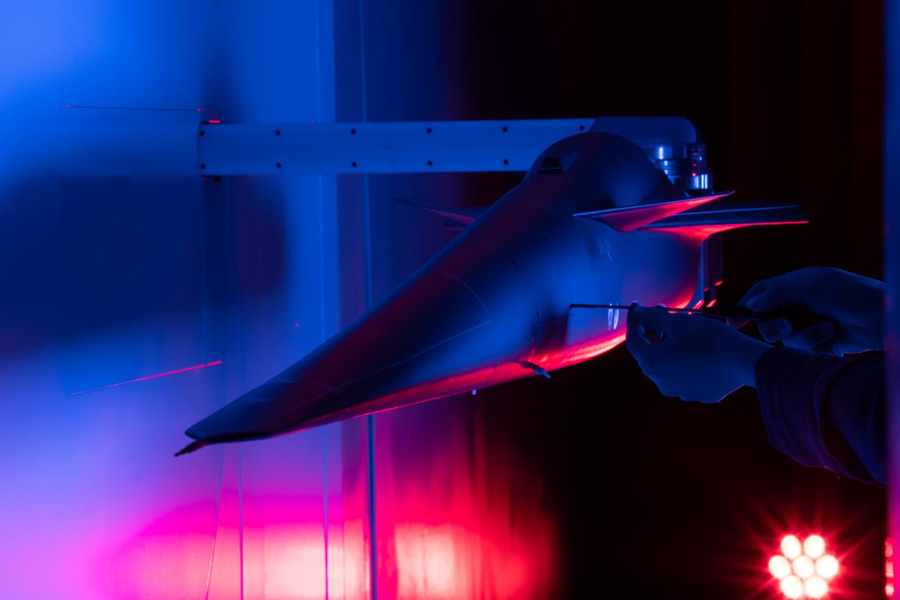
Event: Forebody and Nose - Windtunnel Testing A technician works on the X-59 model during testing in the low-speed wind tunnel at Lockheed Martin Skunk Works in Palmdale, California. These tests gave the team measurements of wind flow angle around the aircraft’s nose and confirmed computer predictions made using computational fluid dynamics (CFD) software tools. The data will be fed into the aircraft flight control system to tell the pilot the aircraft’s altitude, speed, and angle. This is part of NASA’s Quesst mission which plans to help enable supersonic air travel over land.
VSHAIP test in 7x10ft#1 W.T. (multiple model configruations) V-22 helicopter shipboard aerodynamic interaction program: SH-3G and Osprey models fix with V-22 Blades on deck of aircraft carrier
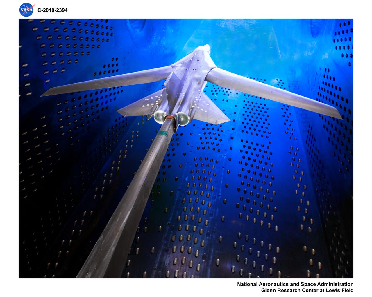
Truss-Braced Wind Model installed in the Ames 11x11 Foot Wind Tunnel for testing. The Truss-Braced model is part of the Subsonic Ultra Green Aircraft Research Project (SUGAR)
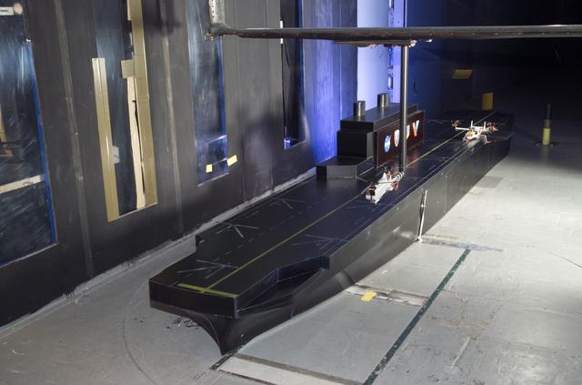
VSHAIP test in 7x10ft#1 W.T. (multiple model configruations) V-22 helicopter shipboard aerodynamic interaction program: SH-3G and Osprey models fix with V-22 Blades on deck of aircraft carrier
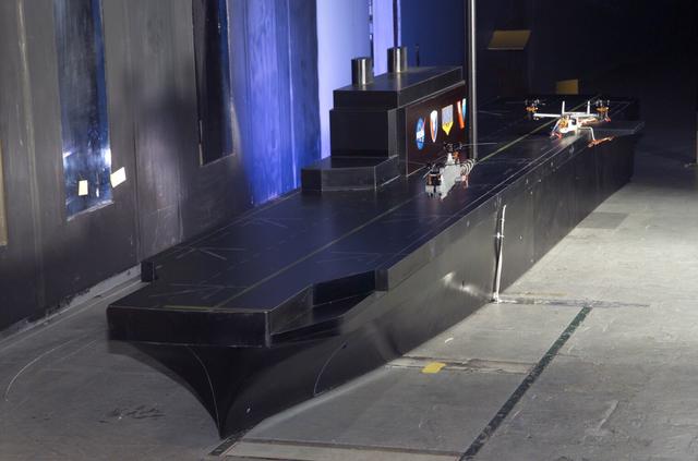
VSHAIP test in 7x10ft#1 W.T. (multiple model configruations) V-22 helicopter shipboard aerodynamic interaction program: SH-3G and Osprey models fix with V-22 Blades on deck of aircraft carrier
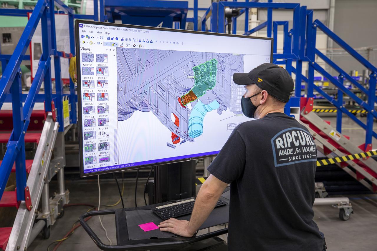
A Lockheed Martin technician looks at the connector installation on the cad model of the X-59 airplane. The aircraft, under construction at Lockheed Martin Skunk Works in Palmdale, California, will demonstrate the ability to fly supersonic while reducing the loud sonic boom to a quiet sonic thump.
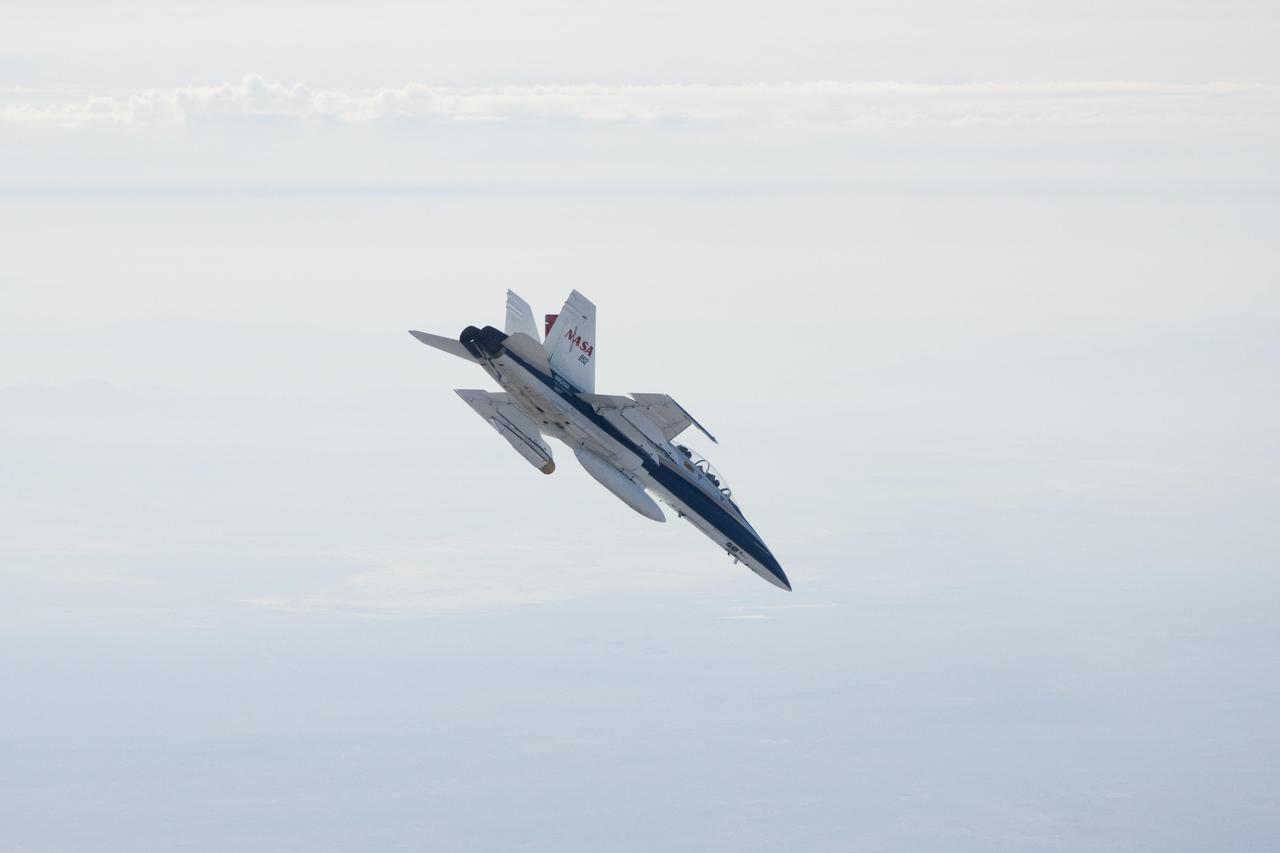
A NASA Dryden Flight Research Center F/A-18 852 aircraft makes a 40-degree dive during June 2011 flight tests of a Mars landing radar. A test model of the landing radar for NASA Mars Science Laboratory mission is inside a pod under the left wing.

Photographed on: 01/12/78. -- Various views of a model aircraft at the Lunar Landing Facility.
7x10ft#1 W. T. aircraft carrier (model ship) installation for oil flow tests
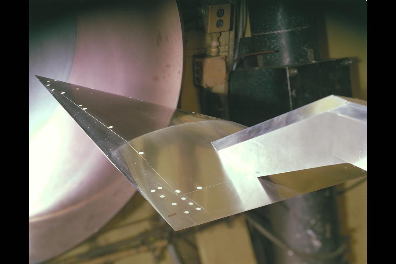
Brimmer All Body Hypersonic Aircraft Model 3.5ft W.T. Test-260 Flow Visualization
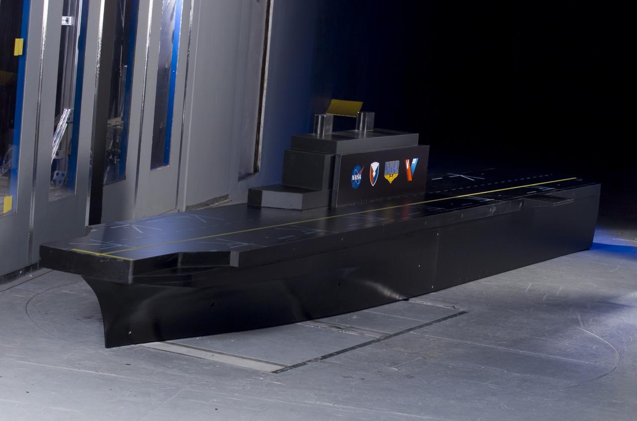
Facility Aerodynamic Validation and Operational Research (FAVOR) aircraft model hardware in 8x6 Supersonic Wind Tunnel (SWT)
Facility Aerodynamic Validation and Operational Research (FAVOR) aircraft model hardware in 8x6 Supersonic Wind Tunnel (SWT)
7x10ft#1 W. T. aircraft carrier (model ship) installation for oil flow tests with Bill Warmbrodt
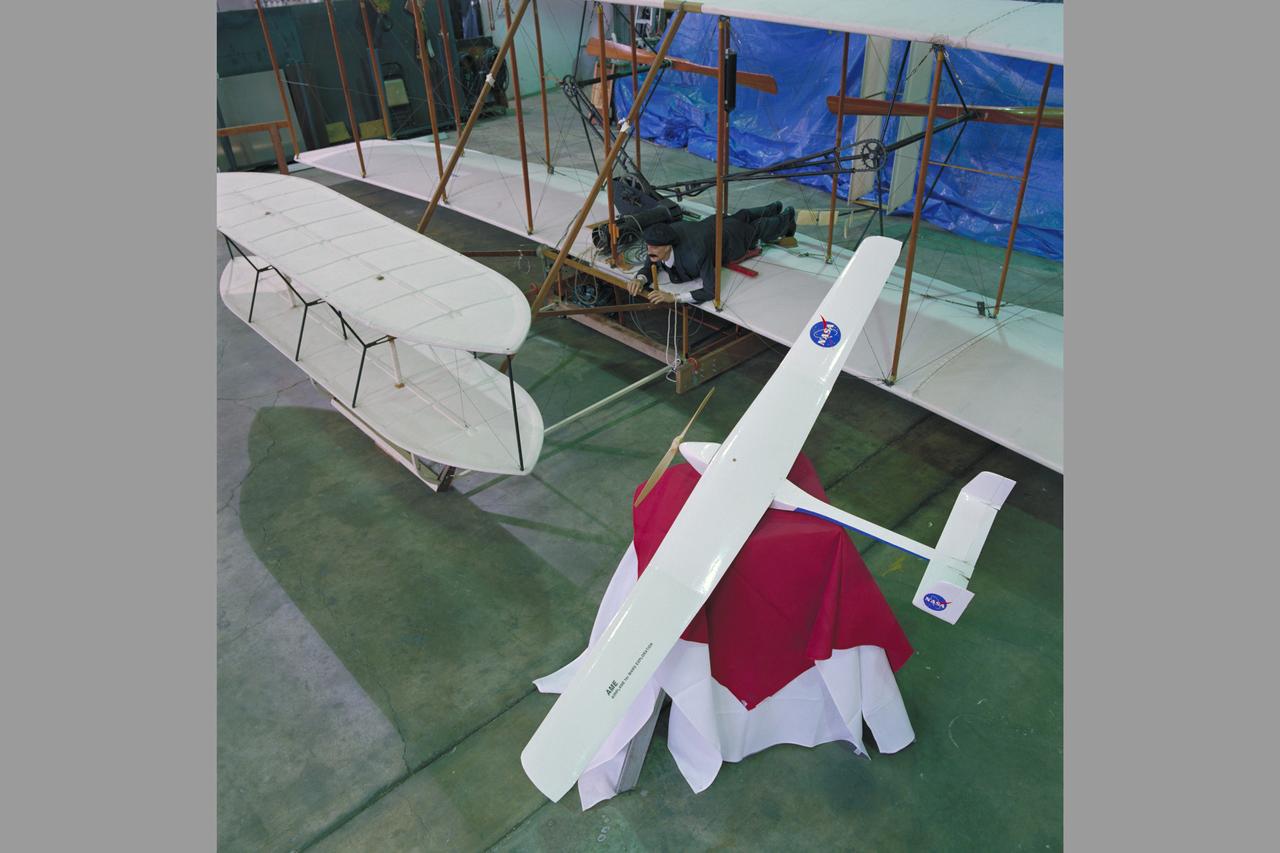
A model of the Ames Mars micromission concept aircraft is shown beside the Wright Flyer replica in the high bay of Ames 40x80ft. wind tunnel
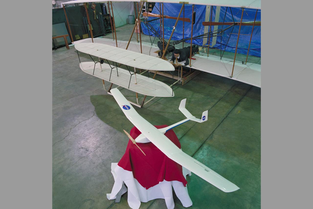
A model of the Ames Mars micromission concept aircraft is shown beside the Wright Flyer replica in the high bay of Ames 40x80ft. wind tunnel
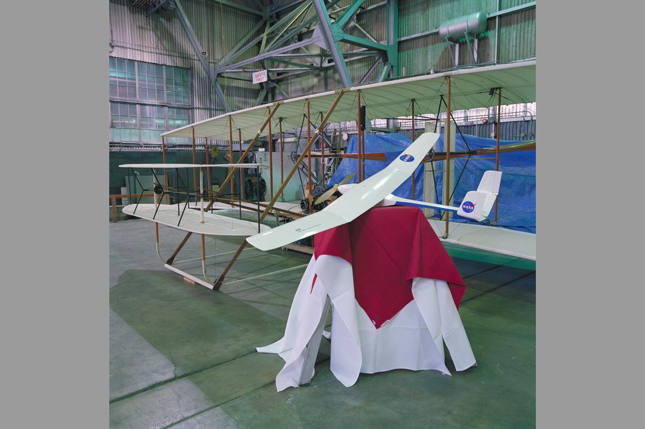
A model of the Ames Mars micromission concept aircraft is shown beside the Wright Flyer replica in the high bay of Ames 40x80ft. wind tunnel
Truss-braced wind model installed in the Ames 11x11 Foot Wind Tunnel for testing as part of the Subsonic Ultra Green Aircraft Research Project (SUGAR)
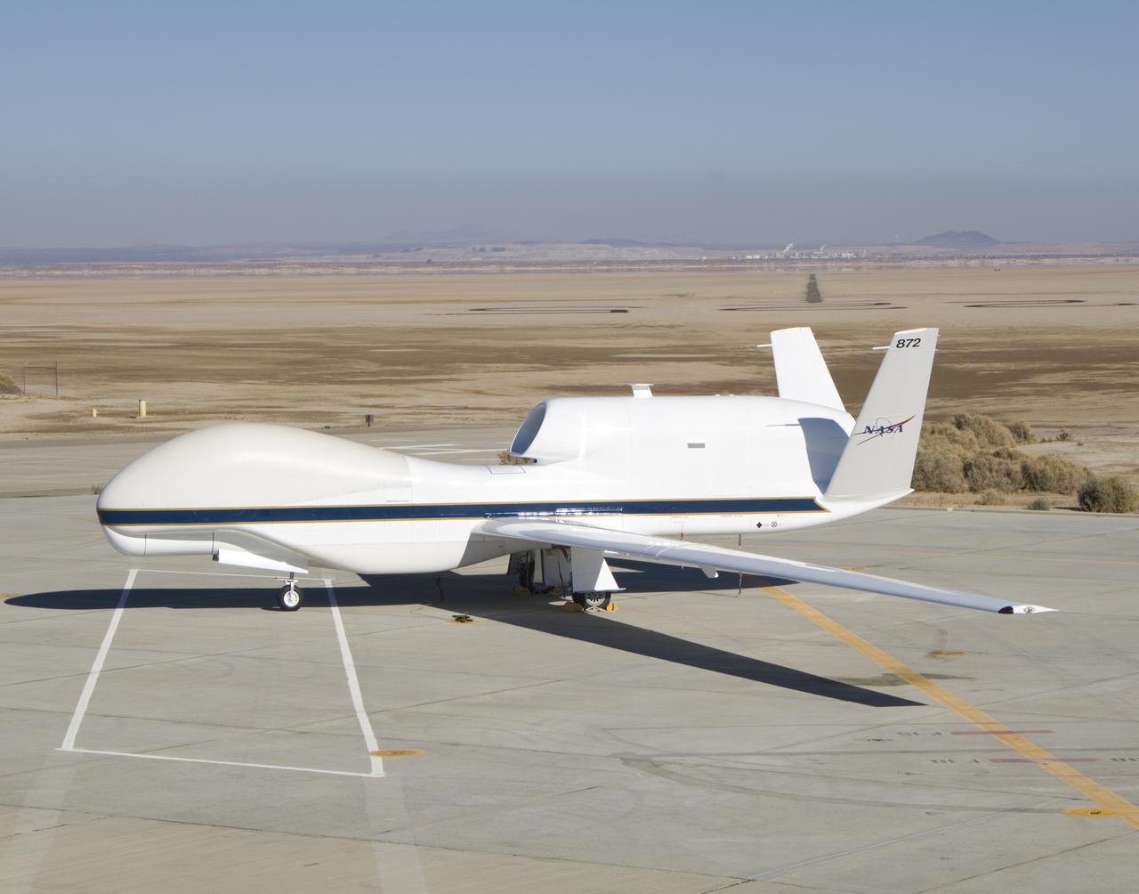
In its new white-and-blue NASA livery, an early development model of the Global Hawk unmanned aircraft rests on the ramp at the Dryden Flight Research Center.
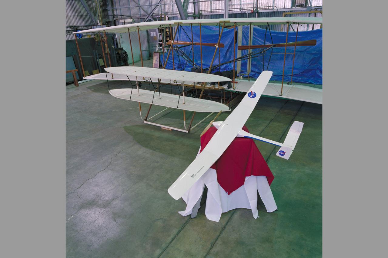
A model of the Ames Mars micromission concept aircraft is shown beside the Wright Flyer replica in the high bay of Ames 40x80ft. wind tunnel
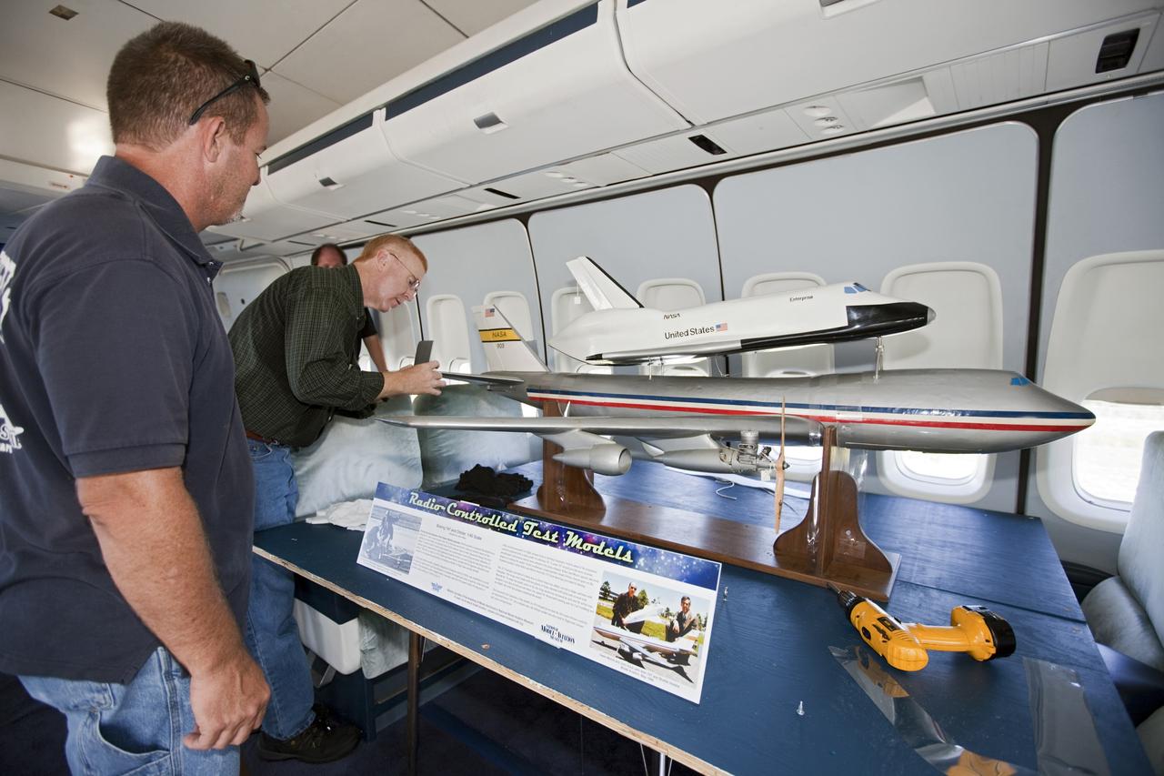
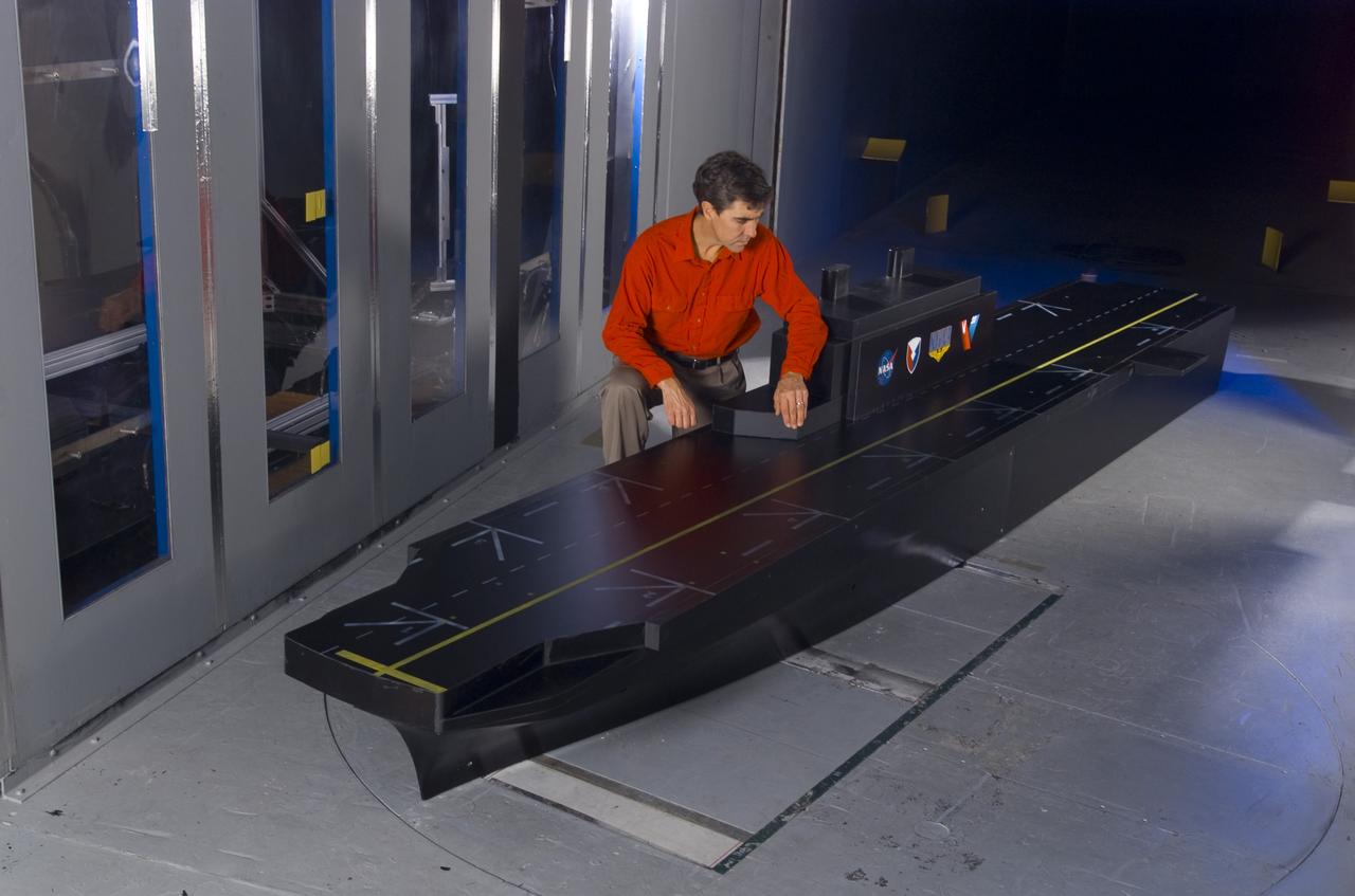
CAPE CANAVERAL, Fla. – Reporters look over a model of the Shuttle Carrier Aircraft, or SCA, and a space shuttle during a tour of the real Shuttle Carrier Aircraft. The model is a radio-controlled scale version of the modified 747 that was used to test theories for how the space shuttle would separate from the SCA during approach and landing tests. Photo credit: NASA/Kim Shiflett
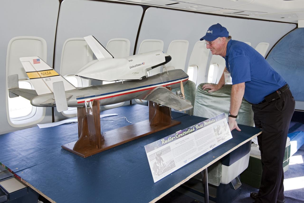
CAPE CANAVERAL, Fla. – A visitor looks over a model of the Shuttle Carrier Aircraft, or SCA, and a space shuttle during a tour of the real Shuttle Carrier Aircraft. The model is a radio-controlled scale version of the modified 747 that was used to test theories for how the space shuttle would separate from the SCA during approach and landing tests. Photo credit: NASA/Kim Shiflett
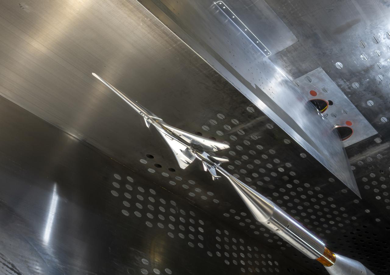
The X-59 Commercial Supersonic Transport model is installed upside down in the test section of the GRC 8x6 Supersonic wind tunnel. The blade hanging from the top of the tunnel will be measuring the shock waves coming from the bottom of the model during testing. The shock waves coming from the bottom of the model represent the sonic boom reaching the ground during flight. The shape of the model is designed so as to greatly reduce the shock waves to prevent the typical boom coming from a supersonic aircraft. Commercial Supersonic Transport, CST Project, X-59 Sonic Boom Test Model, in the 8x6-foot Supersonic Wind Tunnel, SWT
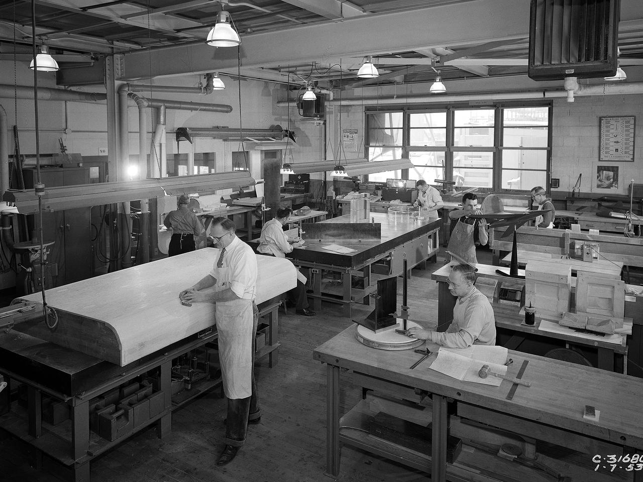
Craftsmen work in the wood model shop at the National Advisory Committee for Aeronautics (NACA) Lewis Flight Propulsion Laboratory. The Fabrication Division created almost all of the equipment and models used at the laboratory. The Fabrication Shop building contained a number of specialized shops in the 1940s and 1950s. These included a Machine Shop, Sheet Metal Shop, Wood Model and Pattern Shop, Instrument Shop, Thermocouple Shop, Heat Treating Shop, Metallurgical Laboratory, and Fabrication Office. The Wood Model and Pattern Shop created everything from control panels and cabinets to aircraft models molds for sheet metal work.

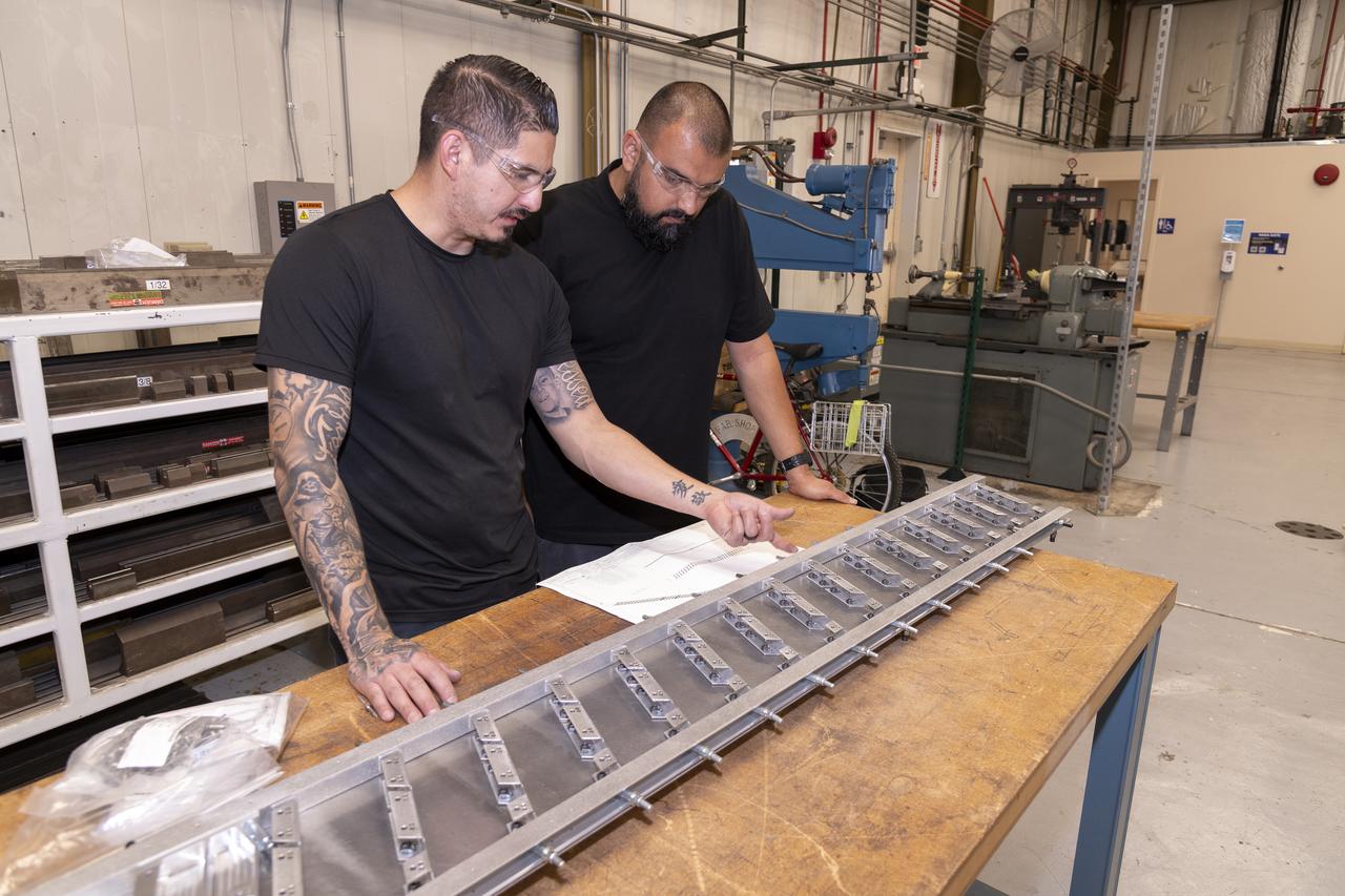
Matthew Sanchez attaches the strut and the wing to ensure they fit together as intended for a 10-foot model of the Transonic Truss-Braced Wing at NASA’s Armstrong Flight Research Center, in Edwards, California. The aircraft concept involves a wing braced on an aircraft using diagonal struts that also add lift and could result in significantly improved aerodynamics.
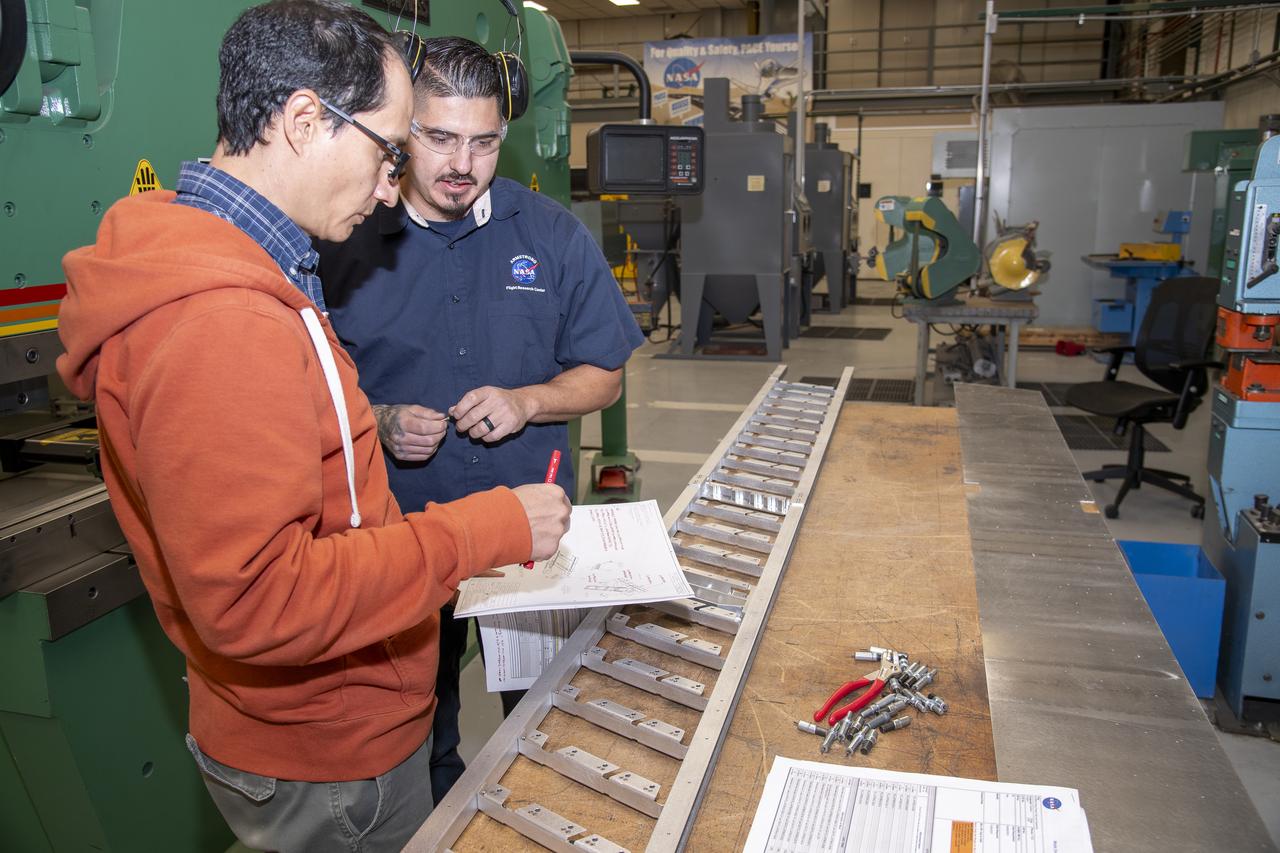
Matthew Sanchez consults with Andrew Holguin on the strut for a 10-foot model of the Transonic Truss-Braced Wing at NASA’s Armstrong Flight Research Center, in Edwards, California. The aircraft concept involves a wing braced on an aircraft using diagonal struts that also add lift and could result in significantly improved aerodynamics.
German Escobar works on milling the strut frame assembly for a 10-foot model of the Transonic Truss-Braced Wing at NASA’s Armstrong Flight Research Center, in Edwards, California. The aircraft concept involves a wing braced on an aircraft using diagonal struts that also add lift and could result in significantly improved aerodynamics.
Matthew Sanchez assembles wing ribs for a 10-foot model of the Transonic Truss-Braced Wing at NASA’s Armstrong Flight Research Center, in Edwards, California. The aircraft concept involves a wing braced on an aircraft using diagonal struts that also add lift and could result in significantly improved aerodynamics.
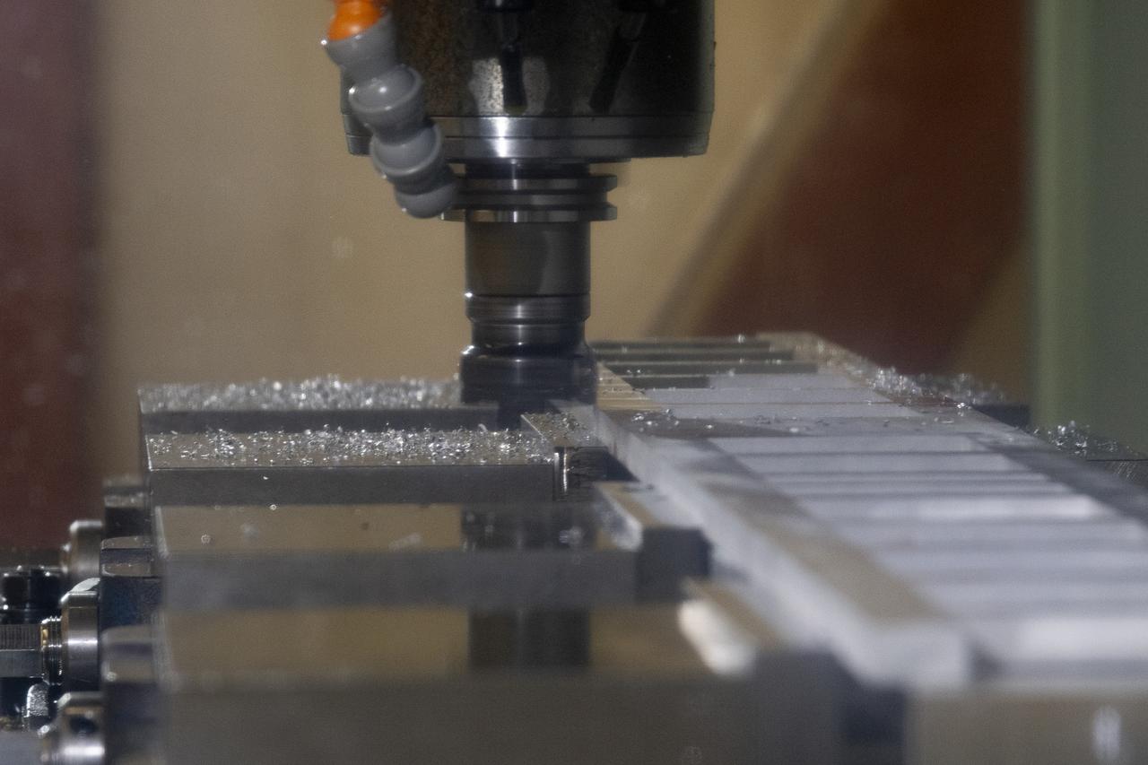
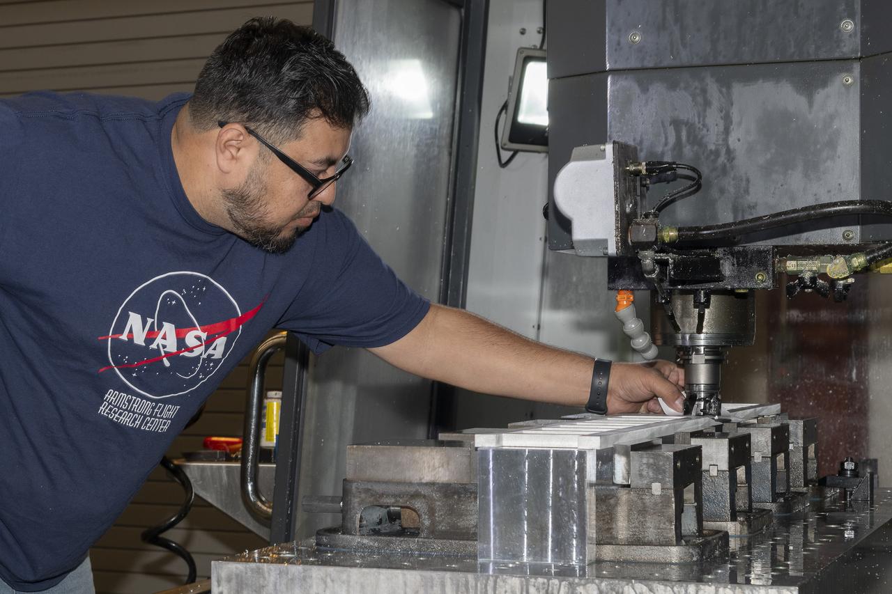
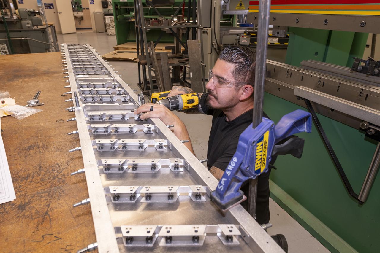
A milling machine drills holes in the strut frame assembly for a 10-foot model of the Transonic Truss-Braced Wing at NASA’s Armstrong Flight Research Center, in Edwards, California. The aircraft concept involves a wing braced on an aircraft using diagonal struts that also add lift and could result in significantly improved aerodynamics.
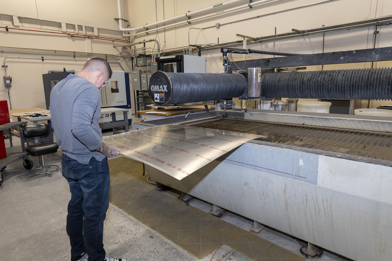
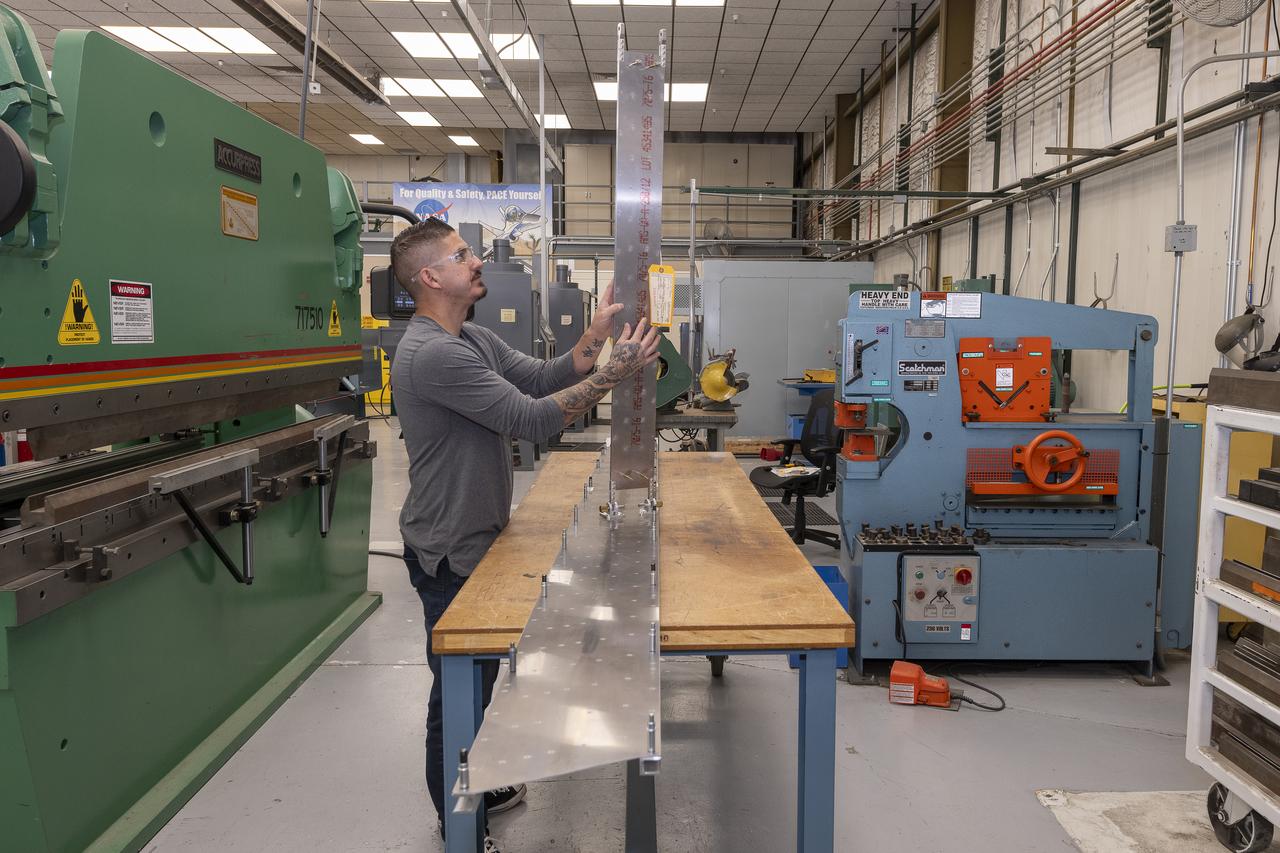
Matthew Sanchez prepares a sheet of aluminum that will be cut into the outer layer of the strut for the 10-foot model of the Transonic Truss-Braced Wing at NASA’s Armstrong Flight Research Center, in Edwards, California. The aircraft concept involves a wing braced on an aircraft using diagonal struts that also add lift and could result in significantly improved aerodynamics.
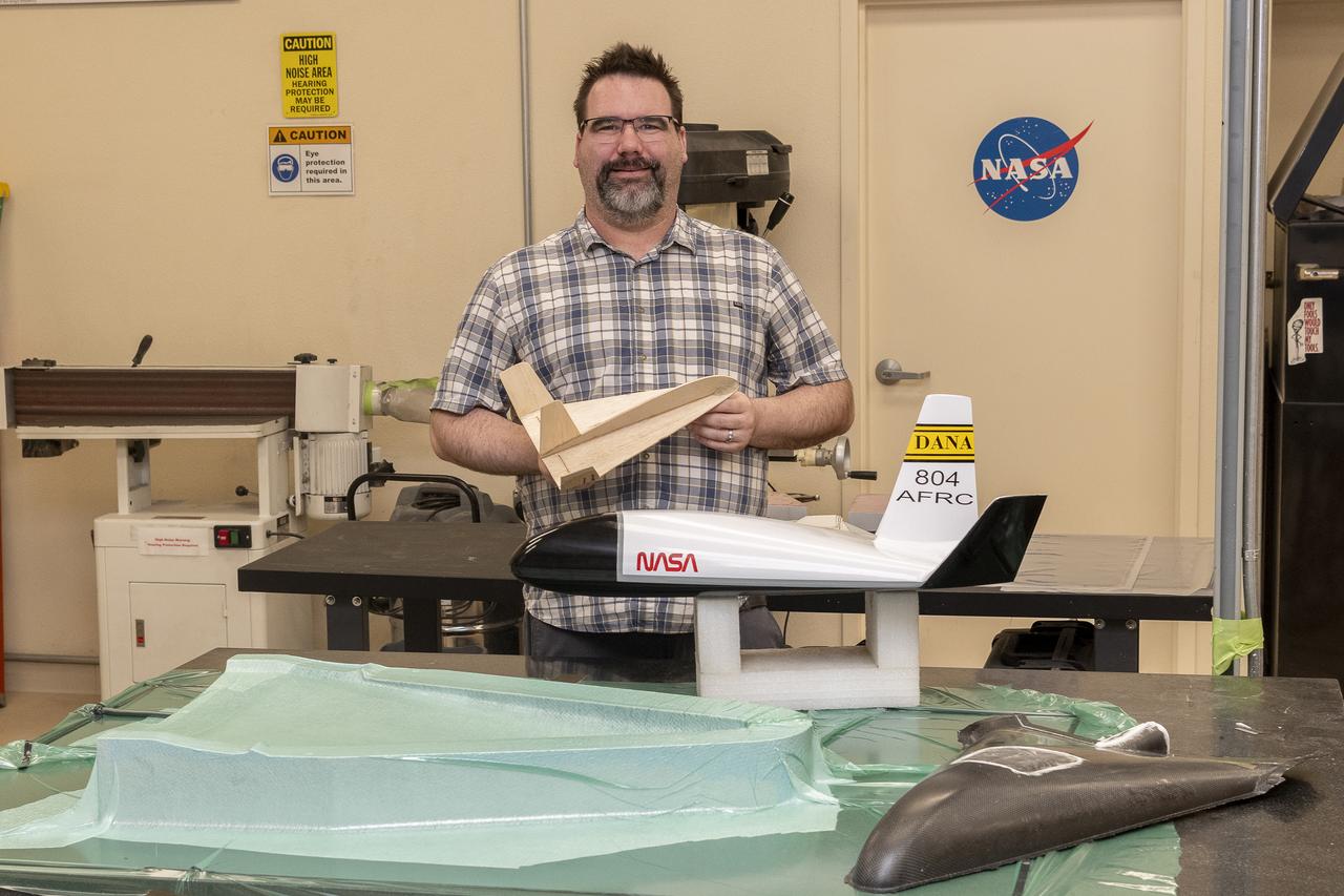
John Bodylski holds a balsa wood model of his proposed aircraft that could be an atmospheric probe. Directly in front of him is a fully assembled version of the aircraft and a large section of a second prototype at NASA’s Armstrong Flight Research Center in Edwards, California.
Matthew Sanchez assembles wing ribs to the 10-foot model of the Transonic Truss-Braced Wing at NASA’s Armstrong Flight Research Center, in Edwards, California. The aircraft concept involves a wing braced on an aircraft using diagonal struts that also add lift and could result in significantly improved aerodynamics.
Matthew Sanchez attaches the strut and the wing to ensure they fit together as intended for a 10-foot model of the Transonic Truss-Braced Wing at NASA’s Armstrong Flight Research Center, in Edwards, California. The aircraft concept involves a wing braced on an aircraft using diagonal struts that also add lift and could result in significantly improved aerodynamics.
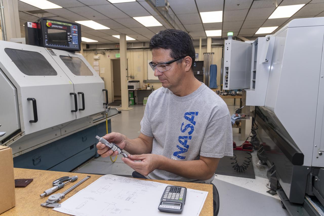
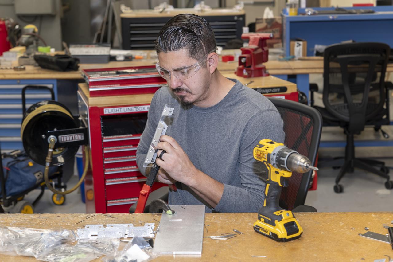
Jose Vasquez verifies a jury strut adaptor created for a 10-foot model of the Transonic Truss-Braced Wing at NASA’s Armstrong Flight Research Center, in Edwards, California. The aircraft concept involves a wing braced on an aircraft using diagonal struts that also add lift and could result in significantly improved aerodynamics.

Aaron Rumsey and Beto Hinojos carefully add weight to a 6-foot model of the Transonic Truss-Braced Wing at NASA’s Armstrong Flight Research Center, in Edwards, California. The aircraft concept involves a wing braced on an aircraft using diagonal struts that also add lift and could result in significantly improved aerodynamics.

A jury strut adaptor is created for a 10-foot model of the Transonic Truss-Braced Wing at NASA’s Armstrong Flight Research Center, in Edwards, California. The aircraft concept involves a wing braced on an aircraft using diagonal struts that also add lift and could result in significantly improved aerodynamics.
Matthew Sanchez, left, consults with Sal Navarro on assembling wing ribs to the 10-foot model of the Transonic Truss-Braced Wing at NASA’s Armstrong Flight Research Center, in Edwards, California. The aircraft concept involves a wing braced on an aircraft using diagonal struts that also add lift and could result in significantly improved aerodynamics.

An aerospace research engineer and technicians inspect the X-59 Commercial Supersonic Transport model’s installation and alignment before testing. The blade hanging from the top of the tunnel will be measuring the shock waves coming from the model during testing. The intent is to develop a supersonic aircraft with less sonic boom. Commercial Supersonic Transport, CST Project, X-59 Sonic Boom Test Model, in the 8x6-foot Supersonic Wind Tunnel, SWT
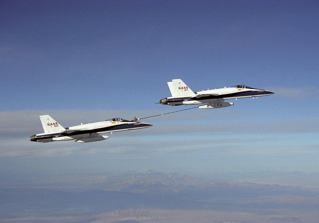
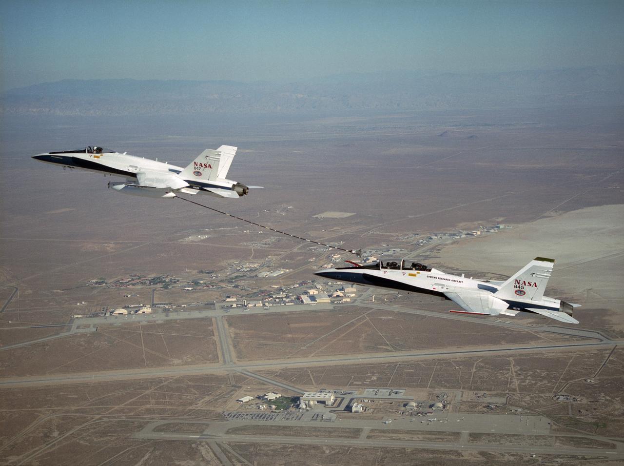
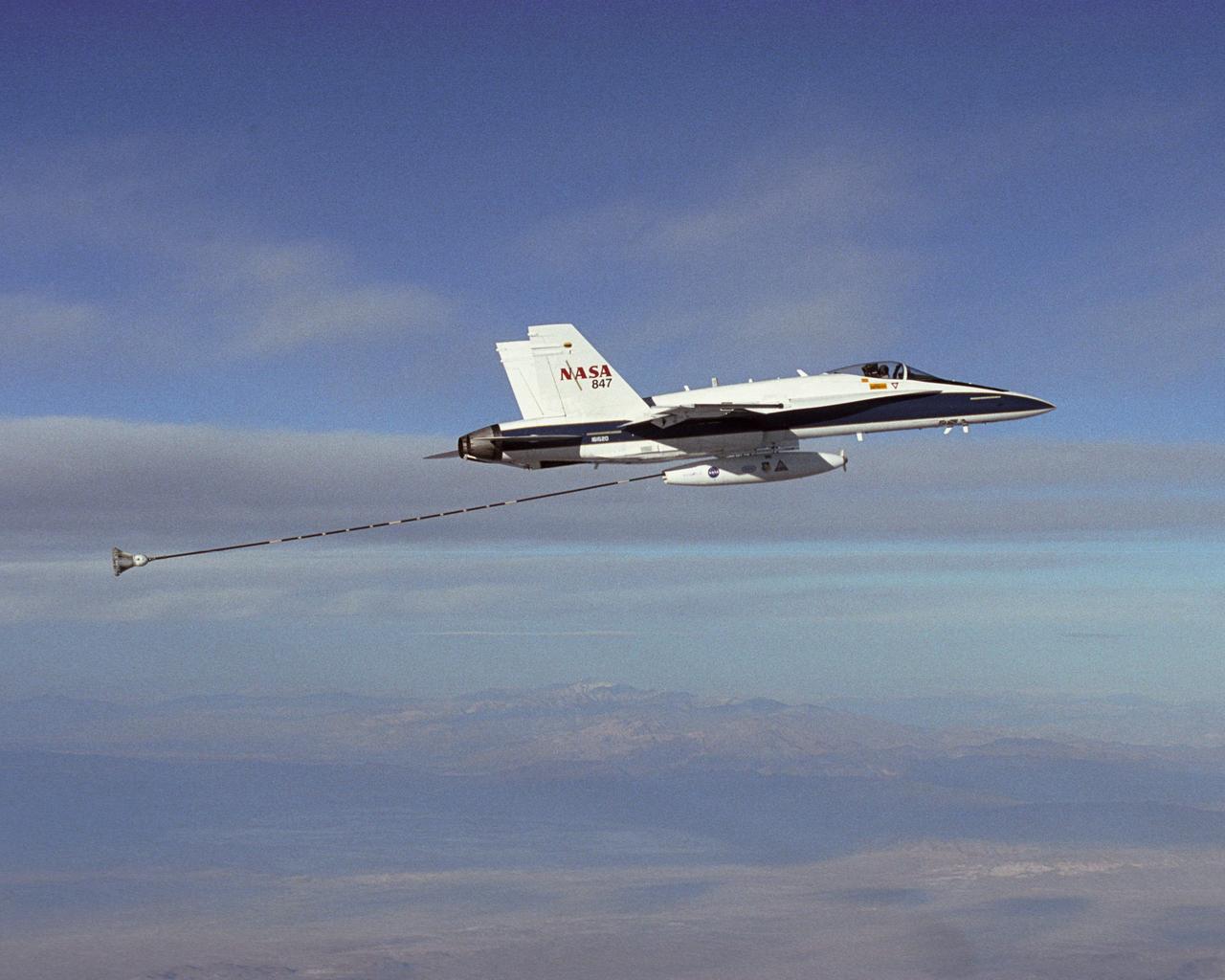
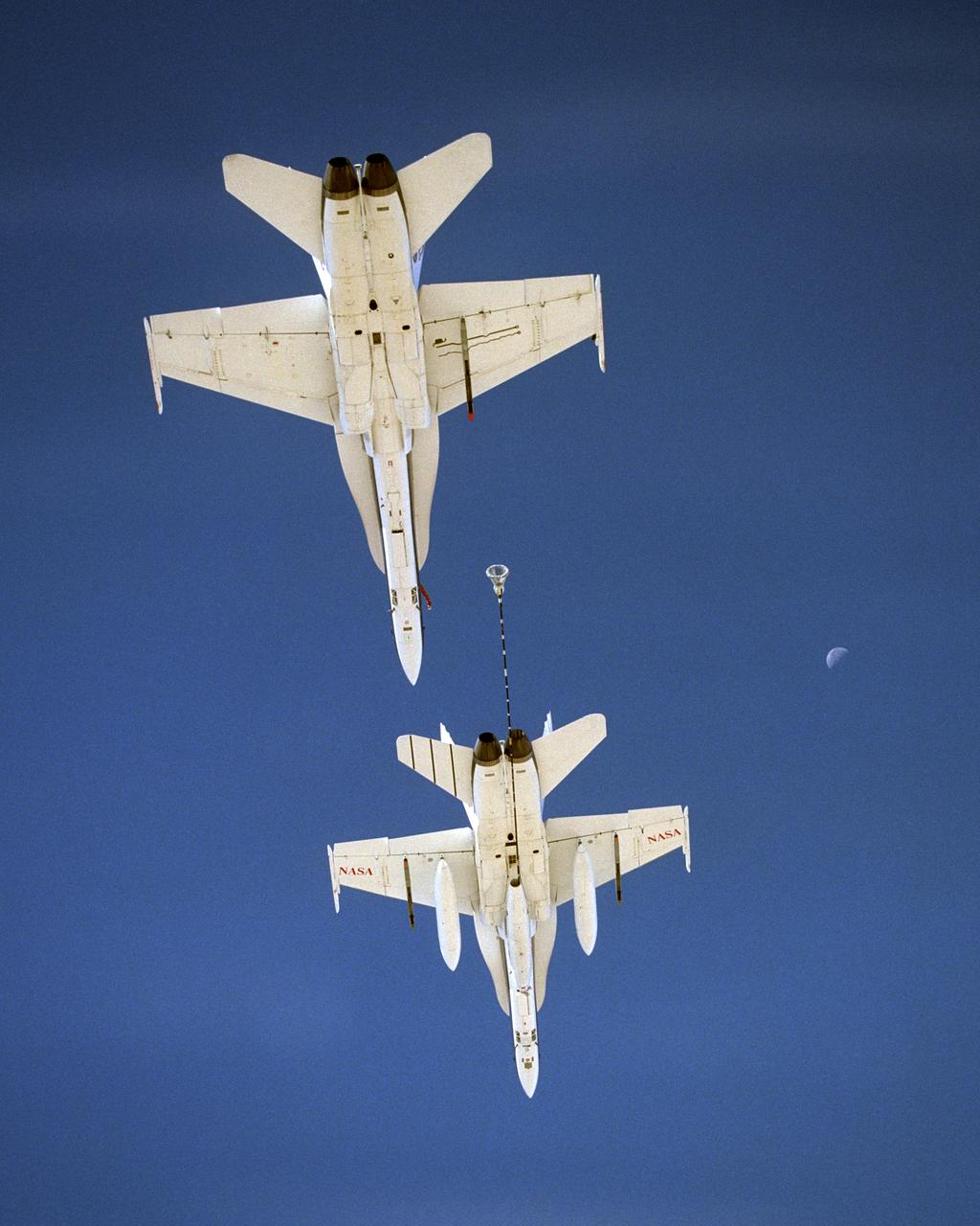
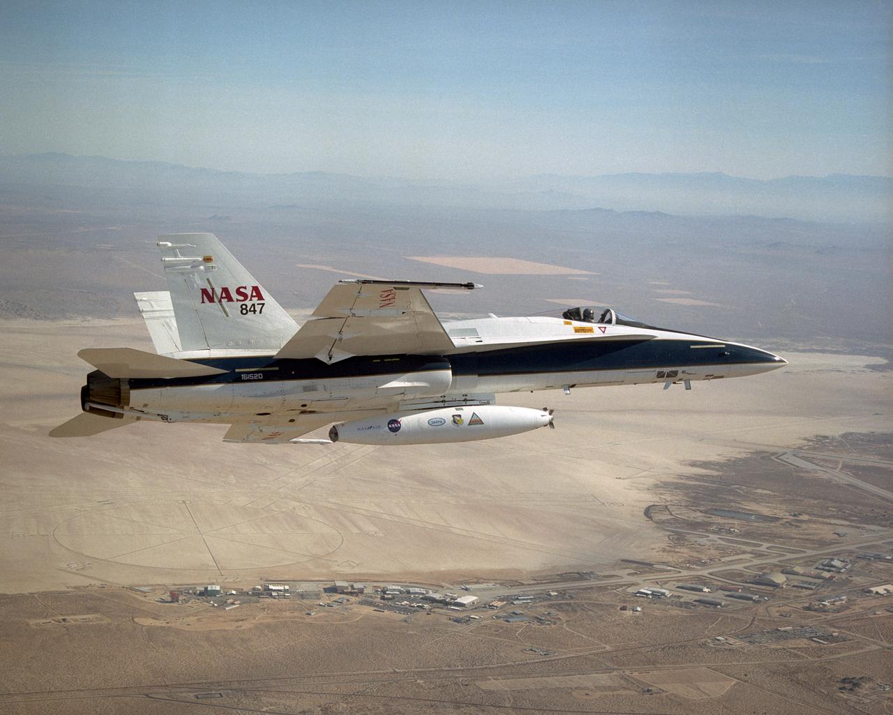
NASA Dryden's Automated Aerial Refueling (AAR) project evaluated the capability of an F/A-18A aircraft as an in-flight refueling tanker with the objective of developing analytical models for an automated aerial refueling system for unmanned air vehicles. The F/A-18 "tanker" aircraft (No. 847) underwent flight test envelope expansion with an aerodynamic pod containing air-refueling equipment carried beneath the fuselage. The second aircraft (No. 843) flew as the receiver aircraft during the study to assess the free-stream hose and drogue dynamics on the F/A-18A.
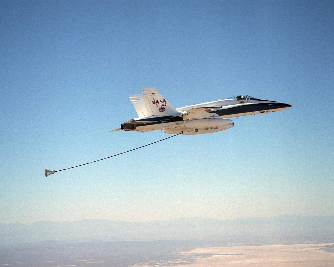
NASA Dryden's Automated Aerial Refueling (AAR) project evaluated the capability of an F/A-18A aircraft as an in-flight refueling tanker with the objective of developing analytical models for an automated aerial refueling system for unmanned air vehicles. The F/A-18 "tanker" aircraft (No. 847) underwent flight test envelope expansion with an aerodynamic pod containing air-refueling equipment carried beneath the fuselage. The second aircraft flew as the receiver aircraft during the study to assess the free-stream hose and drogue dynamics on the F/A-18A.
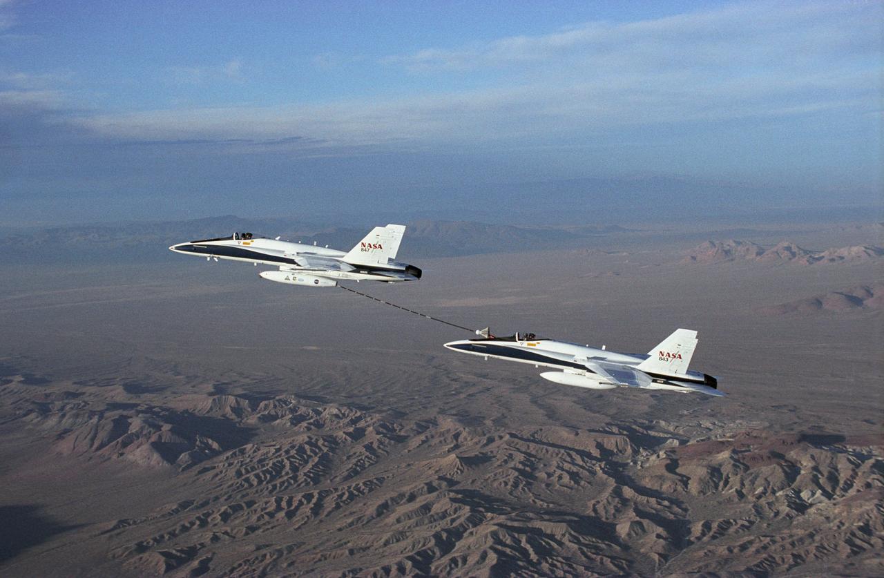
NASA Dryden's Automated Aerial Refueling (AAR) project evaluated the capability of an F/A-18A aircraft as an in-flight refueling tanker with the objective of developing analytical models for an automated aerial refueling system for unmanned air vehicles. The F/A-18 "tanker" aircraft (No. 847) underwent flight test envelope expansion with an aerodynamic pod containing air-refueling equipment carried beneath the fuselage. The second aircraft (No. 843) flew as the receiver aircraft during the study to assess the free-stream hose and drogue dynamics on the F/A-18A.
NASA Dryden's Automated Aerial Refueling (AAR) project evaluated the capability of an F/A-18A aircraft as an in-flight refueling tanker with the objective of developing analytical models for an automated aerial refueling system for unmanned air vehicles. The F/A-18 "tanker" aircraft (No. 847) underwent flight test envelope expansion with an aerodynamic pod containing air-refueling equipment carried beneath the fuselage. The second aircraft flew as the receiver aircraft during the study to assess the free-stream hose and drogue dynamics on the F/A-18A.
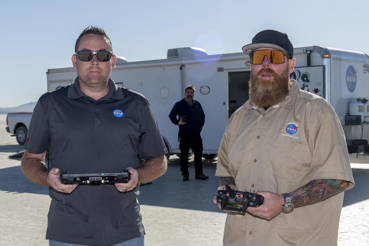
Justin Link, left, unmanned aircraft systems pilot, and Justin Hall, chief pilot for small unmanned aircraft systems, prepare to fly a quad rotor remotely piloted aircraft and an atmospheric probe model on Oct. 22, 2024. John Bodylski, probe principal investigator, watches the preparation for flight. The quad rotor aircraft released the probe above Rogers Dry Lake, a flight area adjacent NASA’s Armstrong Flight Research Center in Edwards, California. The probe was designed and built at the center.
NASA Dryden's Automated Aerial Refueling (AAR) project evaluated the capability of an F/A-18A aircraft as an in-flight refueling tanker with the objective of developing analytical models for an automated aerial refueling system for unmanned air vehicles. The F/A-18 "tanker" aircraft (No. 847) underwent flight test envelope expansion with an aerodynamic pod containing air-refueling equipment carried beneath the fuselage. The second aircraft (No. 843) flew as the receiver aircraft during the study to assess the free-stream hose and drogue dynamics on the F/A-18A.
NASA Dryden's Automated Aerial Refueling (AAR) project evaluated the capability of an F/A-18A aircraft as an in-flight refueling tanker with the objective of developing analytical models for an automated aerial refueling system for unmanned air vehicles. The F/A-18 "tanker" aircraft (No. 847) underwent flight test envelope expansion with an aerodynamic pod containing air-refueling equipment carried beneath the fuselage. The second aircraft flew as the receiver aircraft during the study to assess the free-stream hose and drogue dynamics on the F/A-18A.
3/4 front view of model with flaps up. V/STOL Aircraft: Wind tunnel investigation of rotating cylinder applied to training edge flaps for high lift & low-speed control.

3/4 rear view of model with flaps down with Cecil E. MacDonald. V/STOL Aircraft: Wind tunnel investigation of rotating cylinder applied to training edge flaps for high lift & low-speed control.
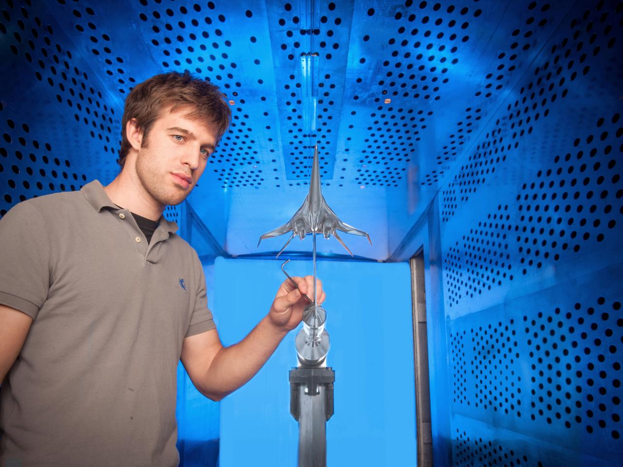
NASA Glenn engineer Gary Williamson with a small model of a future low-boom supersonic aircraft used for testing in the 8' x 6' Supersonic Wind Tunnel at NASA Glenn Research Center.
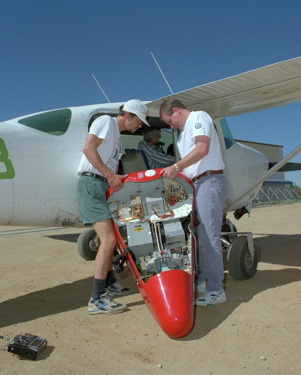
Crew members load a Spacewedge subscale research model into a Cessna aircraft for flight testing in 1996. The Spacewedge was drop-launched from the Cessna and then glided back to a soft landing under a steerable parafoil.
3/4 rear view of model with flaps down. V/STOL Aircraft: Wind tunnel investigation of rotating cylinder applied to training edge flaps for high lift & low-speed control.
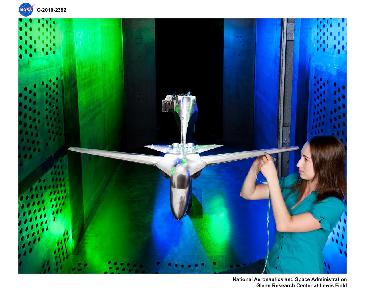
Truss-braced wind model installed in the Ames 11x11 Foot Wind Tunnel for testing as part of the Subsonic Ultra Green Aircraft Research Project (SUGAR) Shown here with test engineer Greg Gatlin, Langley Research Center.
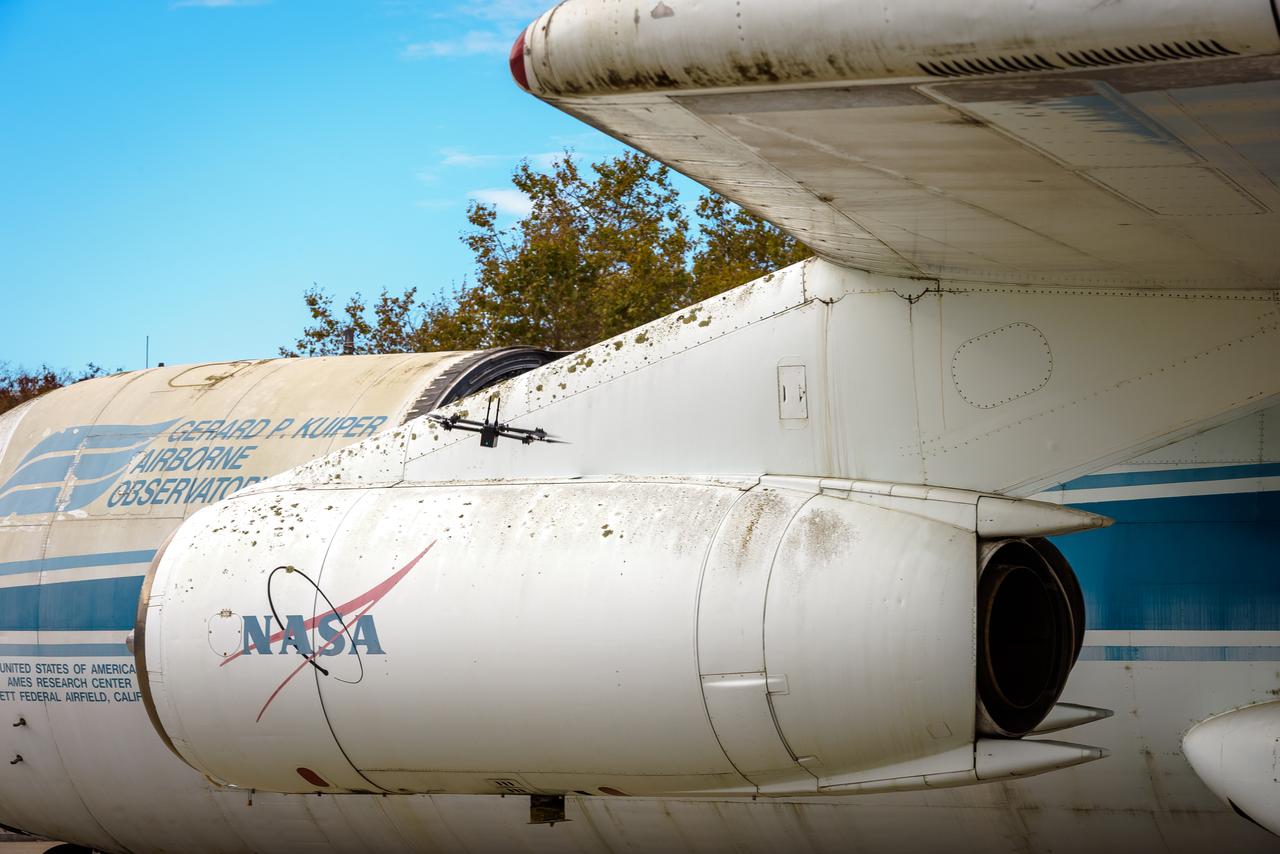
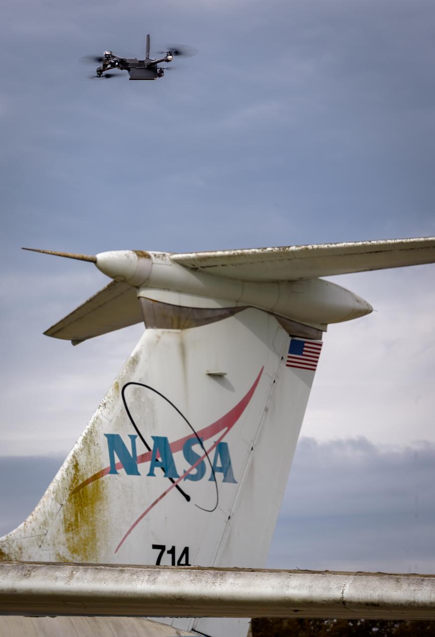
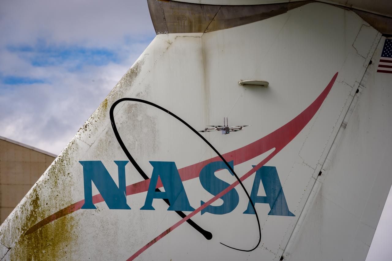
The drone follows an autonomously defined path around the modified C-141 Kuiper Airborne Observatory, (KAO) (NASA-714), on the N211 apron. The drone photographs the aircraft with a visible and infrared camera which are processed using a photogrammetry software package called Pix4D that converts them into a 3D model. Scanning the aircraft is the first phase of documenting the aircraft demolition as well as an opportunity to train pilots to operate the Pix4D software.
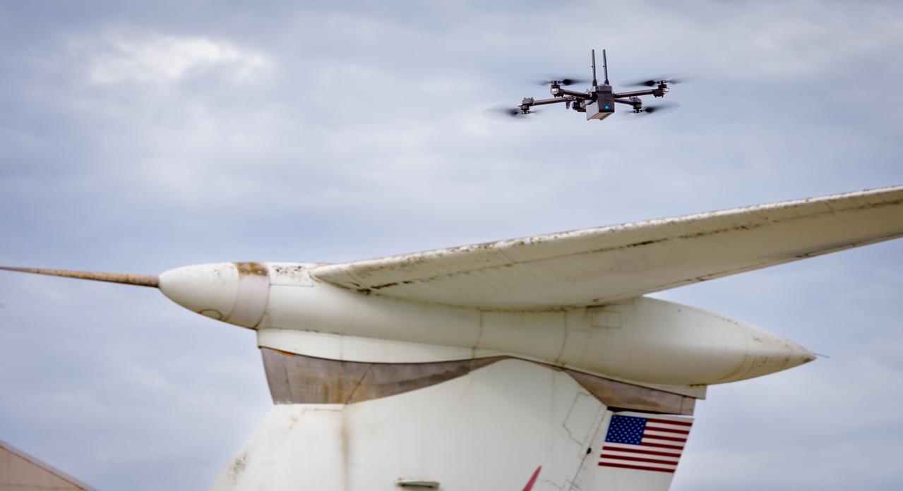
The drone follows an autonomously defined path around the modified C-141 Kuiper Airborne Observatory, (KAO) (NASA-714), on the N211 apron. The drone photographs the aircraft with a visible and infrared camera which are processed using a photogrammetry software package called Pix4D that converts them into a 3D model. Scanning the aircraft is the first phase of documenting the aircraft demolition as well as an opportunity to train pilots to operate the Pix4D software.
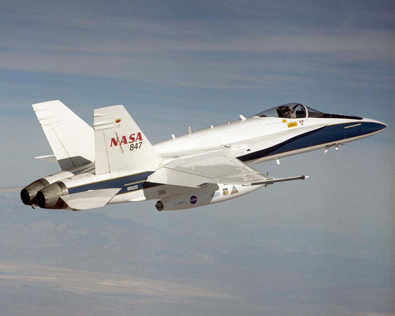
A NASA F/A-18 flies over the Dryden Flight Research Center and Rogers Dry Lake on December 11, 2002. The aircraft participated in the Automated Aerial Refueling (AAR) project. The 300-gallon aerial refueling store seen on the belly of the aircraft carries fuel and a refueling drogue. This aircraft acted as a tanker in the study to develop an aerodynamic model for future automated aerial refueling, especially of unmanned vehicles.
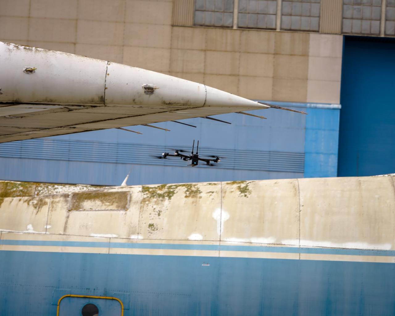
The drone follows an autonomously defined path around the modified C-141 Kuiper Airborne Observatory, (KAO) (NASA-714), on the N211 apron. The drone photographs the aircraft with a visible and infrared camera which are processed using a photogrammetry software package called Pix4D that converts them into a 3D model. Scanning the aircraft is the first phase of documenting the aircraft demolition as well as an opportunity to train pilots to operate the Pix4D software.
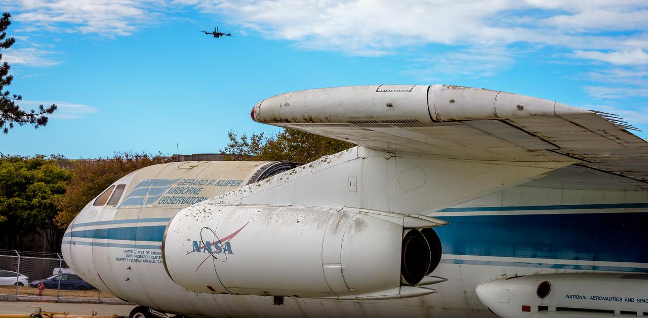
The drone follows an autonomously defined path around the modified C-141 Kuiper Airborne Observatory, (KAO) (NASA-714), on the N211 apron. The drone photographs the aircraft with a visible and infrared camera which are processed using a photogrammetry software package called Pix4D that converts them into a 3D model. Scanning the aircraft is the first phase of documenting the aircraft demolition as well as an opportunity to train pilots to operate the Pix4D software.
A NASA F/A-18 flies over the Dryden Flight Research Center and Rogers Dry Lake on December 11, 2002. The aircraft participated in the Automated Aerial Refueling (AAR) project. The 300-gallon aerial refueling store seen on the belly of the aircraft carries fuel and a refueling drogue. This aircraft acted as a tanker in the study to develop an aerodynamic model for future automated aerial refueling, especially of unmanned vehicles.
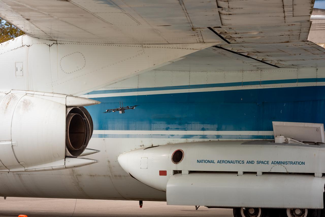
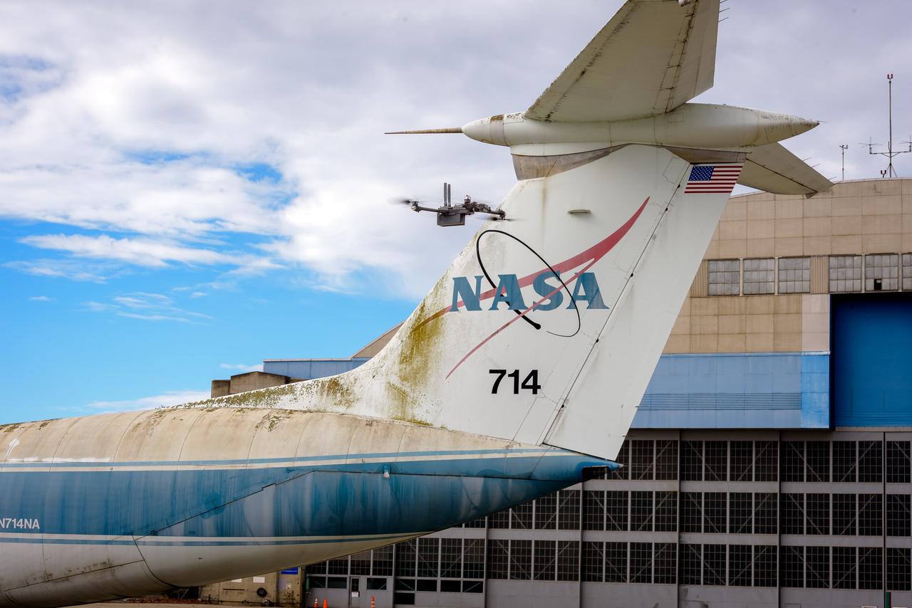
The drone follows an autonomously defined path around the modified C-141 Kuiper Airborne Observatory, (KAO) (NASA-714), on the N211 apron. The drone photographs the aircraft with a visible and infrared camera which are processed using a photogrammetry software package called Pix4D that converts them into a 3D model. Scanning the aircraft is the first phase of documenting the aircraft demolition as well as an opportunity to train pilots to operate the Pix4D software.
The drone follows an autonomously defined path around the modified C-141 Kuiper Airborne Observatory, (KAO) (NASA-714), on the N211 apron. The drone photographs the aircraft with a visible and infrared camera which are processed using a photogrammetry software package called Pix4D that converts them into a 3D model. Scanning the aircraft is the first phase of documenting the aircraft demolition as well as an opportunity to train pilots to operate the Pix4D software.

A NASA F/A-18 flies over the Dryden Flight Research Center and Rogers Dry Lake on December 11, 2002. The aircraft participated in the Automated Aerial Refueling (AAR) project. The 300-gallon aerial refueling store seen on the belly of the aircraft carries fuel and a refueling drogue. This aircraft acted as a tanker in the study to develop an aerodynamic model for future automated aerial refueling, especially of unmanned vehicles.
The drone follows an autonomously defined path around the modified C-141 Kuiper Airborne Observatory, (KAO) (NASA-714), on the N211 apron. The drone photographs the aircraft with a visible and infrared camera which are processed using a photogrammetry software package called Pix4D that converts them into a 3D model. Scanning the aircraft is the first phase of documenting the aircraft demolition as well as an opportunity to train pilots to operate the Pix4D software.
The drone follows an autonomously defined path around the modified C-141 Kuiper Airborne Observatory, (KAO) (NASA-714), on the N211 apron. The drone photographs the aircraft with a visible and infrared camera which are processed using a photogrammetry software package called Pix4D that converts them into a 3D model. Scanning the aircraft is the first phase of documenting the aircraft demolition as well as an opportunity to train pilots to operate the Pix4D software.
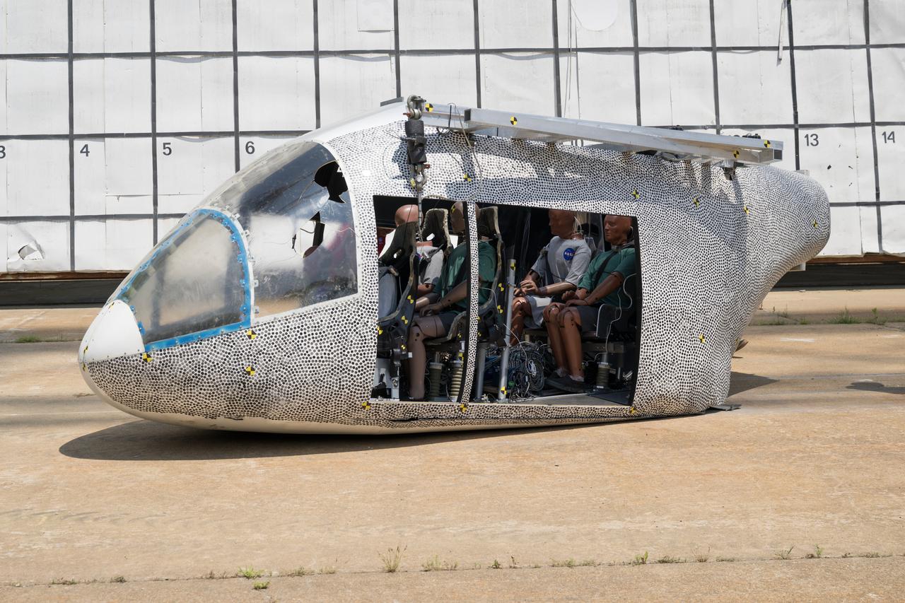
An aircraft body modeled after an air taxi with weighted test dummies inside is shown after a drop test at NASA’s Langley Research Center in Hampton, Virginia. The test was completed June 26 at Langley’s Landing and Impact Research Facility. The aircraft was dropped from a tall steel structure, known as a gantry, after being hoisted about 35 feet in the air by cables. NASA researchers are investigating aircraft materials that best absorb impact forces in a crash.

An aircraft body modeled after an air taxi with weighted test dummies inside is being prepared for a drop test by researchers at NASA’s Langley Research Center in Hampton, Virginia. The test was completed June 26 at Langley’s Landing and Impact Research Facility. The aircraft was dropped from a tall steel structure, known as a gantry, after being hoisted about 35 feet in the air by cables. NASA researchers are investigating aircraft materials that best absorb impact forces in a crash.
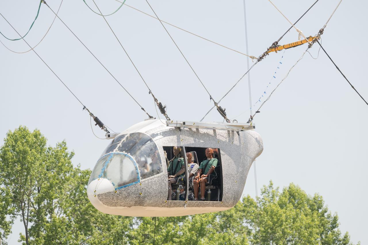
An aircraft body modeled after an air taxi with weighted test dummies inside is hoisted about 35 feet in the air by cables at NASA’s Langley Research Center in Hampton, Virginia. The aircraft was dropped from a tall steel structure, known as a gantry, on June 26 at Langley’s Landing and Impact Research Facility. NASA researchers are investigating aircraft materials that best absorb impact forces in a crash.
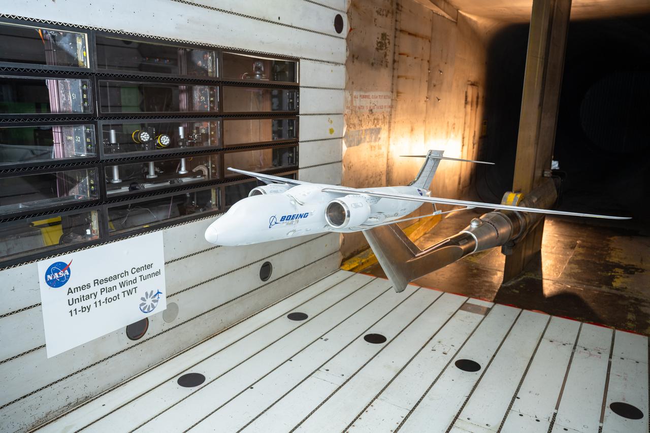
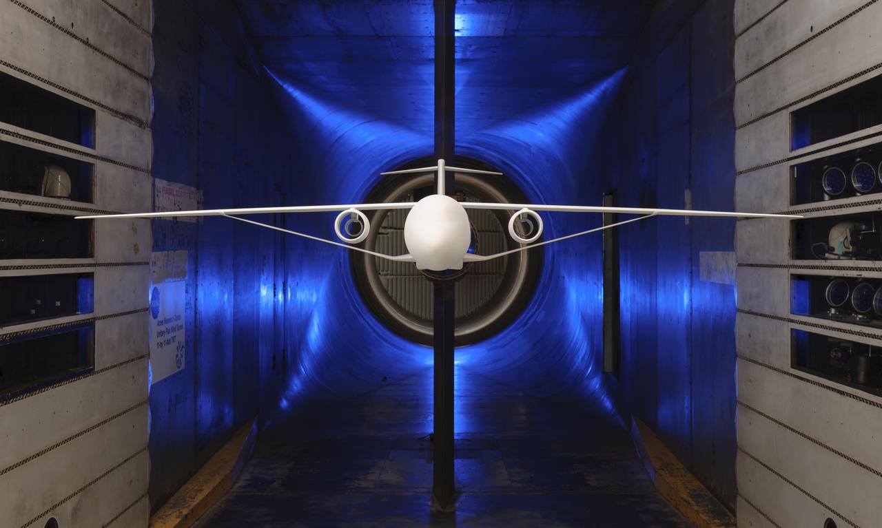
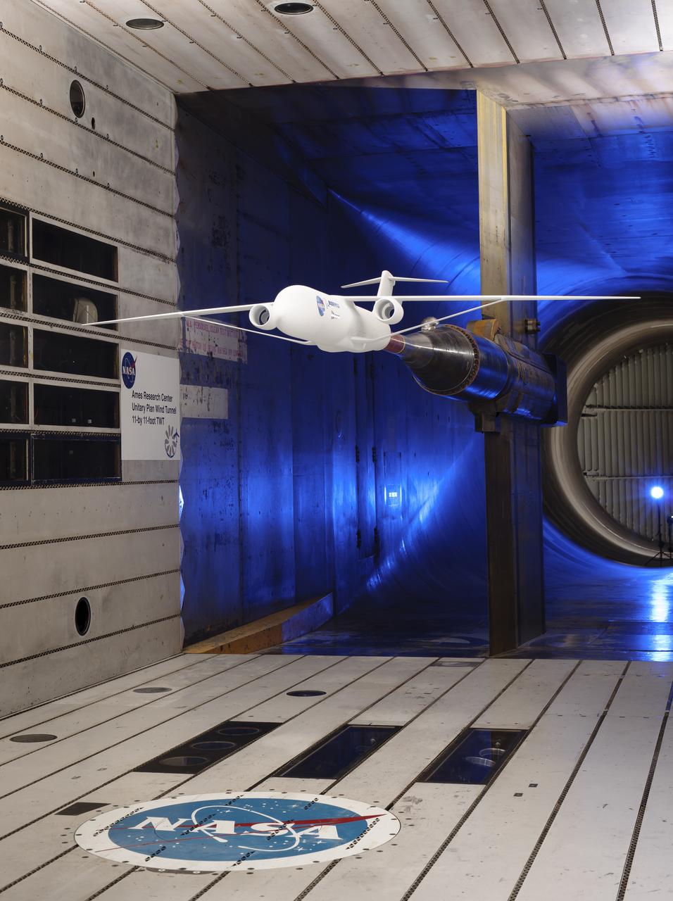
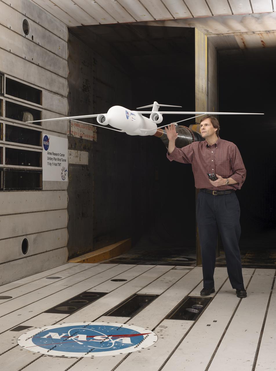
NASA’s Sustainable Flight Demonstrator project completed wind tunnel tests on a Boeing-built X-66 full-span model during a 13-week campaign between January and March 2025. The tests were completed in the 11-Foot Transonic Unitary Plan Facility at NASA’s Ames Research Center in California’s Silicon Valley. The model underwent tests in expected flight conditions to obtain engineering data to help improve the aircraft’s design and flight simulators.
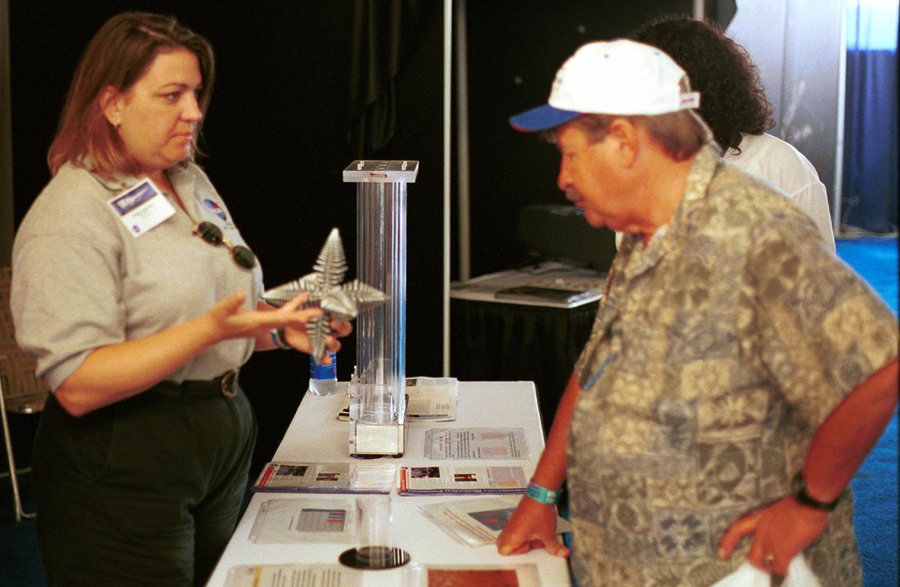
Angie Jackman, a NASA project manager in microgravity research, explains a model of a dendrite to a visitor to the NASA exhibit at AirVenture 2000 sponsored by the Experimental Aircraft Association in Oshkosh, WI. The model depicts microscopic dendrites that grow as molten metals solidify. NASA sponsored three experiments aboard the Space Shuttle that used the microgravity environment to study the formation of large (1 to 4 mm) dendrites without Earth's gravity disrupting their growth. Three advanced follow-on experiments, managed by Jackman, are being developed for the International Space Station (ISS).