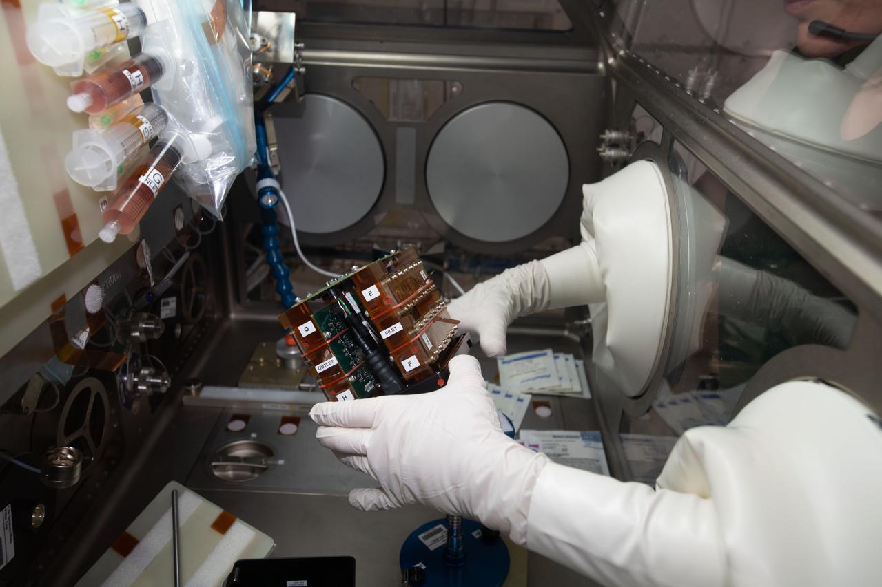
iss062e115367 (3/26/2020) --- Tissue chambers shown during media exchanges and tissue fixations of the Human iPSC-based 3D Microphysiological System for Modeling Cardiac Dysfunction in Microgravity (Engineered Heart Tissue) investigation inside the Life Sciences Glovebox (LSG) in the Japanese Experiment Module (JEM) aboard the International Space Station (ISS). The Engineered Heart Tissues research model could be an effective tool for better understanding cardiac function in response to external factors which would be useful for drug development and other applications related to cardiac dysfunction on Earth.
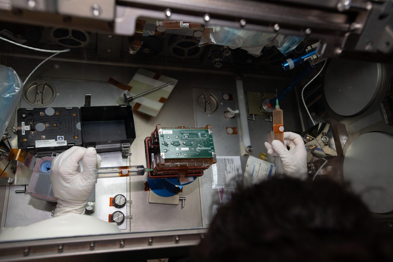
iss062e115350 (3/26/2020) --- Tissue chambers shown during media exchanges and tissue fixations of the Human iPSC-based 3D Microphysiological System for Modeling Cardiac Dysfunction in Microgravity (Engineered Heart Tissue) investigation inside the Life Sciences Glovebox (LSG) in the Japanese Experiment Module (JEM) aboard the International Space Station (ISS). The Engineered Heart Tissues research model could be an effective tool for better understanding cardiac function in response to external factors which would be useful for drug development and other applications related to cardiac dysfunction on Earth.
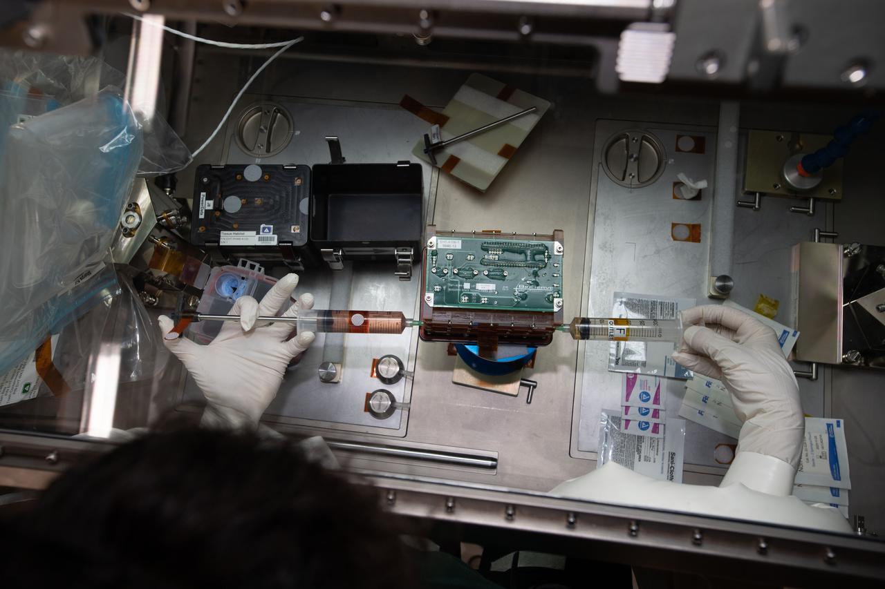
iss062e115333 (3/26/2020) --- Tissue chambers shown during media exchanges and tissue fixations of the Human iPSC-based 3D Microphysiological System for Modeling Cardiac Dysfunction in Microgravity (Engineered Heart Tissue) investigation inside the Life Sciences Glovebox (LSG) in the Japanese Experiment Module (JEM) aboard the International Space Station (ISS). The Engineered Heart Tissues research model could be an effective tool for better understanding cardiac function in response to external factors which would be useful for drug development and other applications related to cardiac dysfunction on Earth.
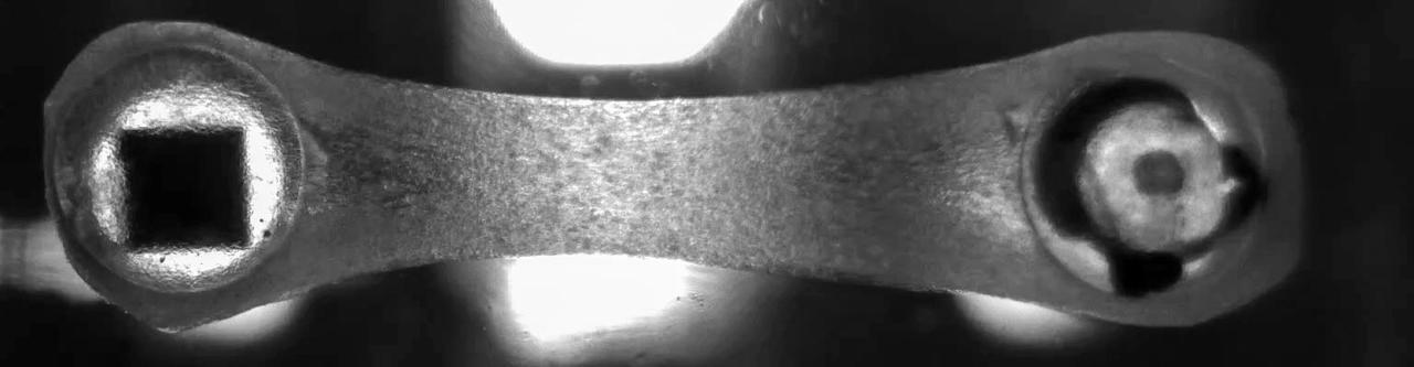
jsc2022e083014 (10/26/2022) --- A preflight image of a beating Engineered Heart Tissue (EHT) for A Human iPSC-based 3D Microphysiological System for Modeling Cardiac Dysfunction in Microgravity (Engineered Heart Tissues-2) investigation. The tissue is fabricated between two posts, one flexible and one rigid. In the flexible post, a square magnet is seen. This magnet enables researchers to measure tissue function using an underlying magnetic sensor, giving real time tissue function data. Image courtesy of Johns Hopkins University.
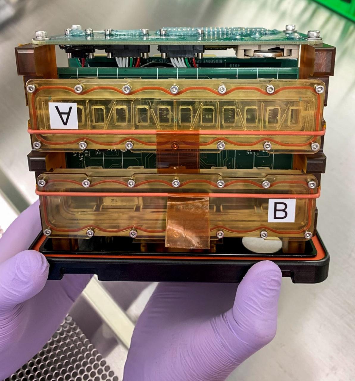
jsc2022e083015 (10/26/2022) --- A preflight image of tissue chambers loaded into the plate habitat (pHAB) for A Human iPSC-based 3D Microphysiological System for Modeling Cardiac Dysfunction in Microgravity (Engineered Heart Tissues-2) investigation. Each tissue chamber contains six tissues and is placed over magnetic sensors on a circuit board to measure contractile function of the Engineered Heart Tissues (EHTs). Image courtesy of Johns Hopkins University.
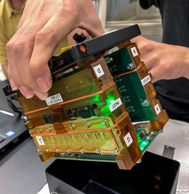
jsc2022e083016 (10/26/2022) --- A preflight image of tissue chambers loaded into the plate habitat (pHAB) for A Human iPSC-based 3D Microphysiological System for Modeling Cardiac Dysfunction in Microgravity (Engineered Heart Tissues-2) investigation. The tissue chambers are placed inside the pHAB lid, creating a fully enclosed system for functional measurements and long-term tissue culture in microgravity. Image courtesy of Johns Hopkins University.
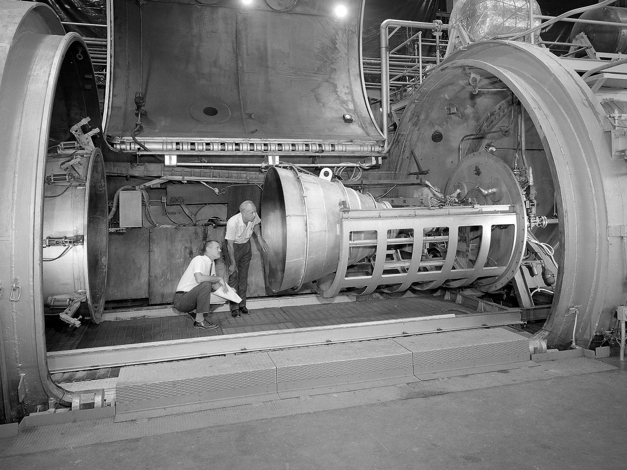
Bill Harrison and Bud Meilander check the setup of an Apollo Contour rocket nozzle in the Propulsion Systems Laboratory at the National Aeronautics and Space Administration (NASA) Lewis Research Center. The Propulsion Systems Laboratory contained two 14-foot diameter test chambers that could simulate conditions found at very high altitudes. The facility was used in the 1960s to study complex rocket engines such as the Pratt and Whitney RL-10 and rocket components such as the Apollo Contour nozzle, seen here. Meilander oversaw the facility’s mechanics and the installation of test articles into the chambers. Harrison was head of the Supersonic Tunnels Branch in the Test Installations Division. Researchers sought to determine the impulse value of the storable propellant mix, classify and improve the internal engine performance, and compare the results with analytical tools. A special setup was installed in the chamber that included a device to measure the thrust load and a calibration stand. Both cylindrical and conical combustion chambers were examined with the conical large area ratio nozzles. In addition, two contour nozzles were tested, one based on the Apollo Service Propulsion System and the other on the Air Force’s Titan transtage engine. Three types of injectors were investigated, including a Lewis-designed model that produced 98-percent efficiency. It was determined that combustion instability did not affect the nozzle performance. Although much valuable information was obtained during the tests, attempts to improve the engine performance were not successful.
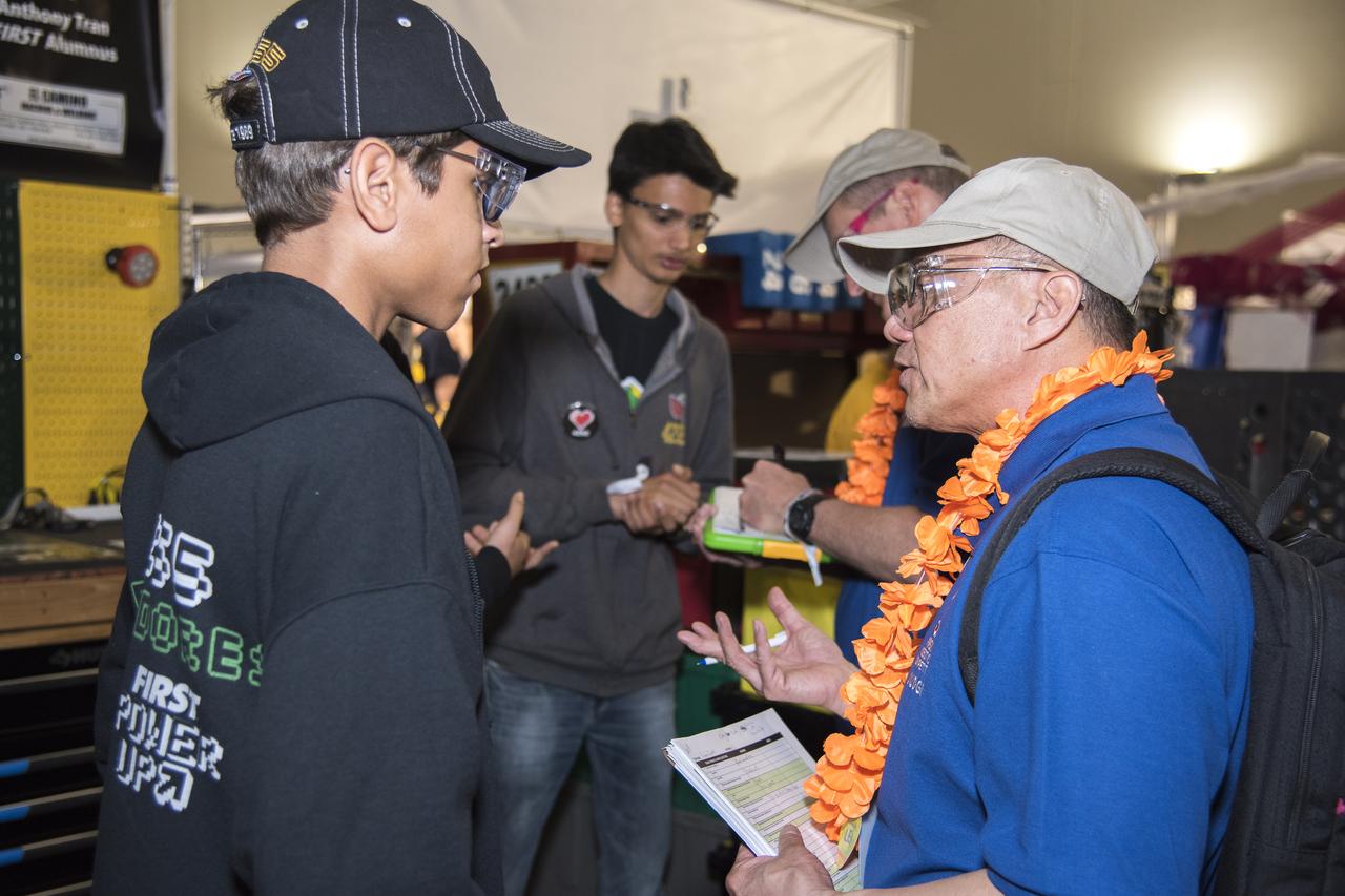
NASA systems engineer, Daniel Eng, right, talks with student participants at the 2019 Aerospace Valley Robotics Competition at the Palmdale Aerospace Academy in Palmdale, California.
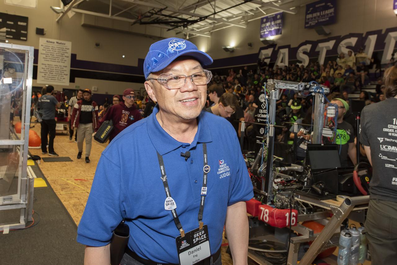
NASA Systems Engineer Daniel Eng serves his second year as a judge for the Aerospace Valley Robotics Competition at the Palmdale Aerospace Academy in Palmdale, California, in 2019.
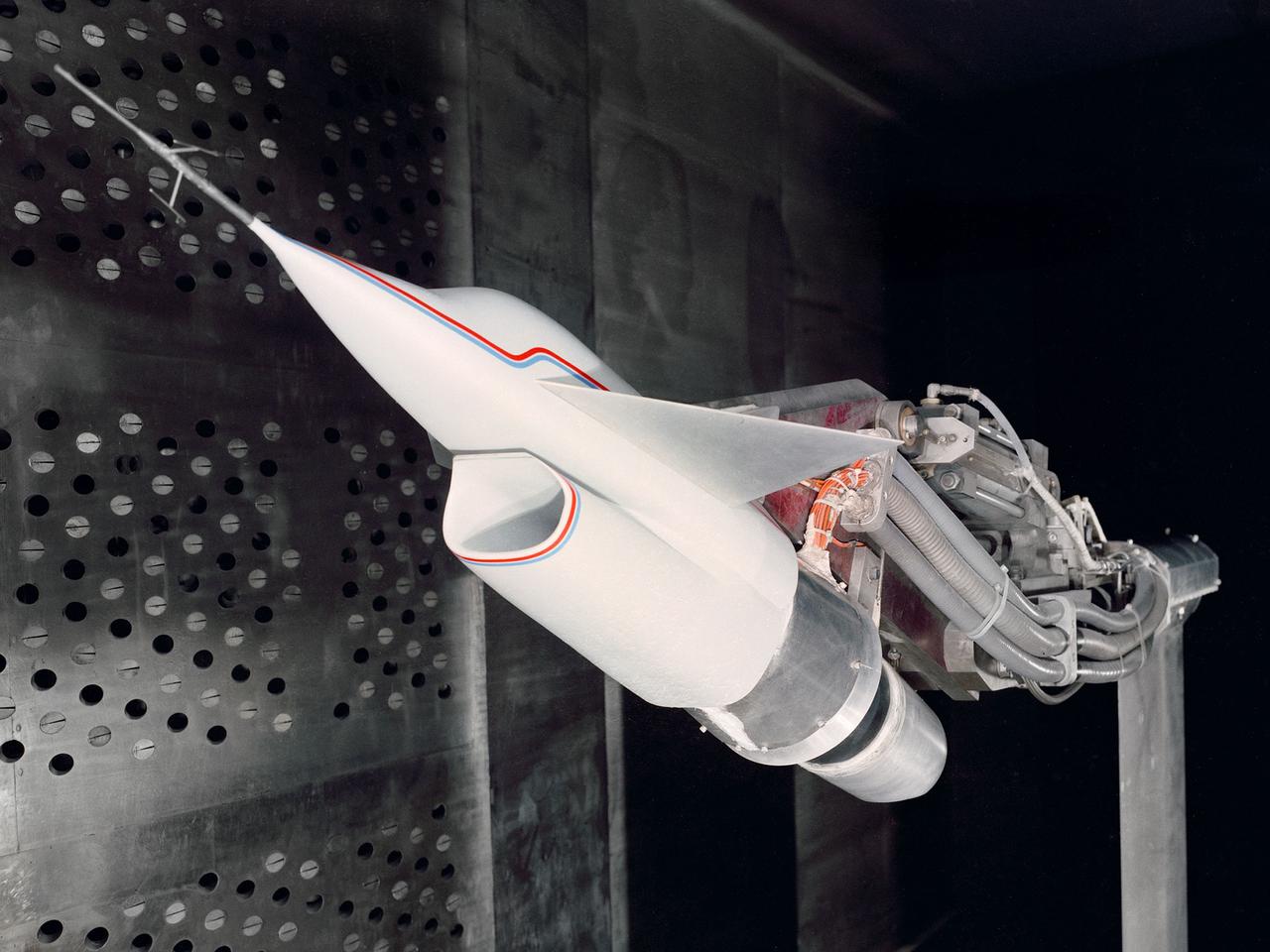
A Highly Maneuverable Aircraft Technology (HiMAT) inlet model installed in the test section of the 8- by 6-Foot Supersonic Wind Tunnel at the National Aeronautics and Space Administration (NASA) Lewis Research Center. Engineers at the Ames Research Center, Dryden Flight Research Center, and Rockwell International designed two pilotless subscale HiMAT vehicles in the mid-1970s to study new design concepts for fighter aircraft in the transonic realm without risking the lives of test pilots. The aircraft used sophisticated technologies such as advanced aerodynamics, composite materials, digital integrated propulsion control, and digital fly-by-wire control systems. In late 1977 NASA Lewis studied the HiMAT’s General Electric J85-21 jet engine in the Propulsion Systems Laboratory. The researchers charted the inlet quality with various combinations anti-distortion screens. HiMAT employed a relatively short and curved inlet compared to actual fighter jets. In the spring of 1979, Larry Smith led an in-depth analysis of the HiMAT inlet in the 8- by 6 tunnel. The researchers installed vortex generators to battle flow separation in the diffuser. The two HiMAT aircraft performed 11 hours of flying over the course of 26 missions from mid-1979 to January 1983 at Dryden and Ames. Although the HiMAT vehicles were considered to be overly complex and expensive, the program yielded a wealth of data that would validate computer-based design tools.
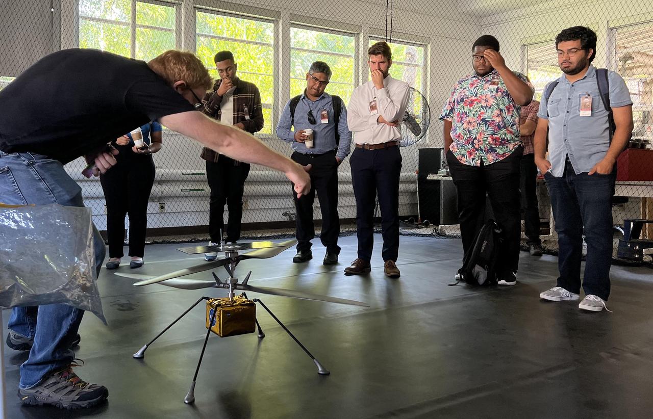
Participants in NASA's Minority Serving Institutions Space Accelerator program surround a full-scale model of NASA's Mars Ingenuity Helicopter as engineer Michael Starch discusses the mission. The group was visiting NASA's Jet Propulsion Laboratory on Aug. 18, 2022. These participants were members of three teams named as awardees in the first-of-its-kind accelerator program, a competition to advance the NASA's goals and meet its needs in the areas of machine learning, artificial intelligence, and development of autonomous systems while also engaging underrepresented academic institutions and reducing barriers for them to submit ideas to the agency. The program provides funding, business training through a 10-week accelerator course, and mentorship to help the teams develop ideas for systems that can operate without human oversight for future science missions in space and on Earth. The teams were made up of professors and students from Fayetteville State University in North Carolina, University of Massachusetts Boston, and California State University, Northridge. At the conclusion of the accelerator, participants arrived in Southern California for a variety of events, including two days at JPL. The program is a partnership between NASA's Science Mission Directorate, its Earth Science Technology Office, the Minority University Research Education Project within the agency's Office of STEM Engagement, JPL, and Starburst, a global aerospace accelerator company based in Los Angeles. https://photojournal.jpl.nasa.gov/catalog/PIA25315
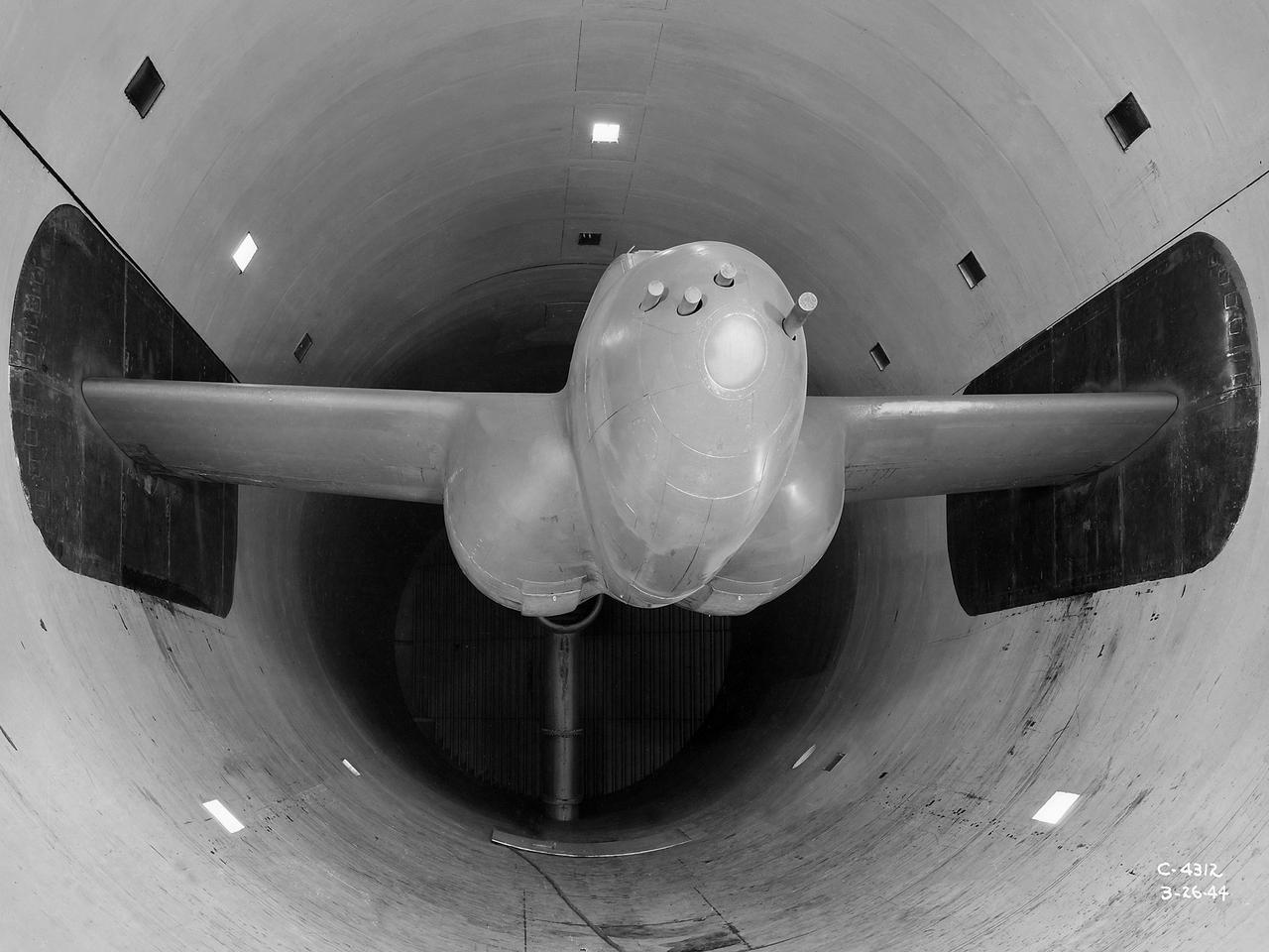
The Altitude Wind Tunnel (AWT) was the National Advisory Committee for Aeronautics (NACA) Aircraft Engine Research Laboratory’s largest and most important test facility in the 1940s. The AWT employed massive cooling and exhaust systems to simulate conditions found at high altitudes. The facility was originally designed to test large piston engines in a simulated flight environment. The introduction of the turbojet during the tunnel’s construction, however, changed the facility’s focus before it became operational. Its first test program was a study of the Bell YP–59A Airacomet and its General Electric I–16 turbojets. The Airacomet was the United States’ first attempt to build a jet aircraft. 1600-horsepower centrifugal engines based on an early design by British engineer Frank Whittle were incorporated into an existing Bell airframe. In October 1942 the Airacomet was secretly test flown in the California desert. The aircraft’s performance was limited, however, and the NACA was asked to study the engines in the AWT. The wind tunnel’s 20-foot-diameter test section was large enough to accommodate entire aircraft with its wing tips and tail removed. The I-16 engines were studied exhaustively in early 1944. They first analyzed the engines in their original configuration and then implemented a boundary layer removal duct, a new nacelle inlet, and new cooling seals. Tests of the modified version showed that the improved distribution of airflow increased the I–16’s performance by 25 percent. The Airacomet never overcame some of its inherent design issues, but the AWT went on to study nearly every emerging US turbojet model during the next decade.
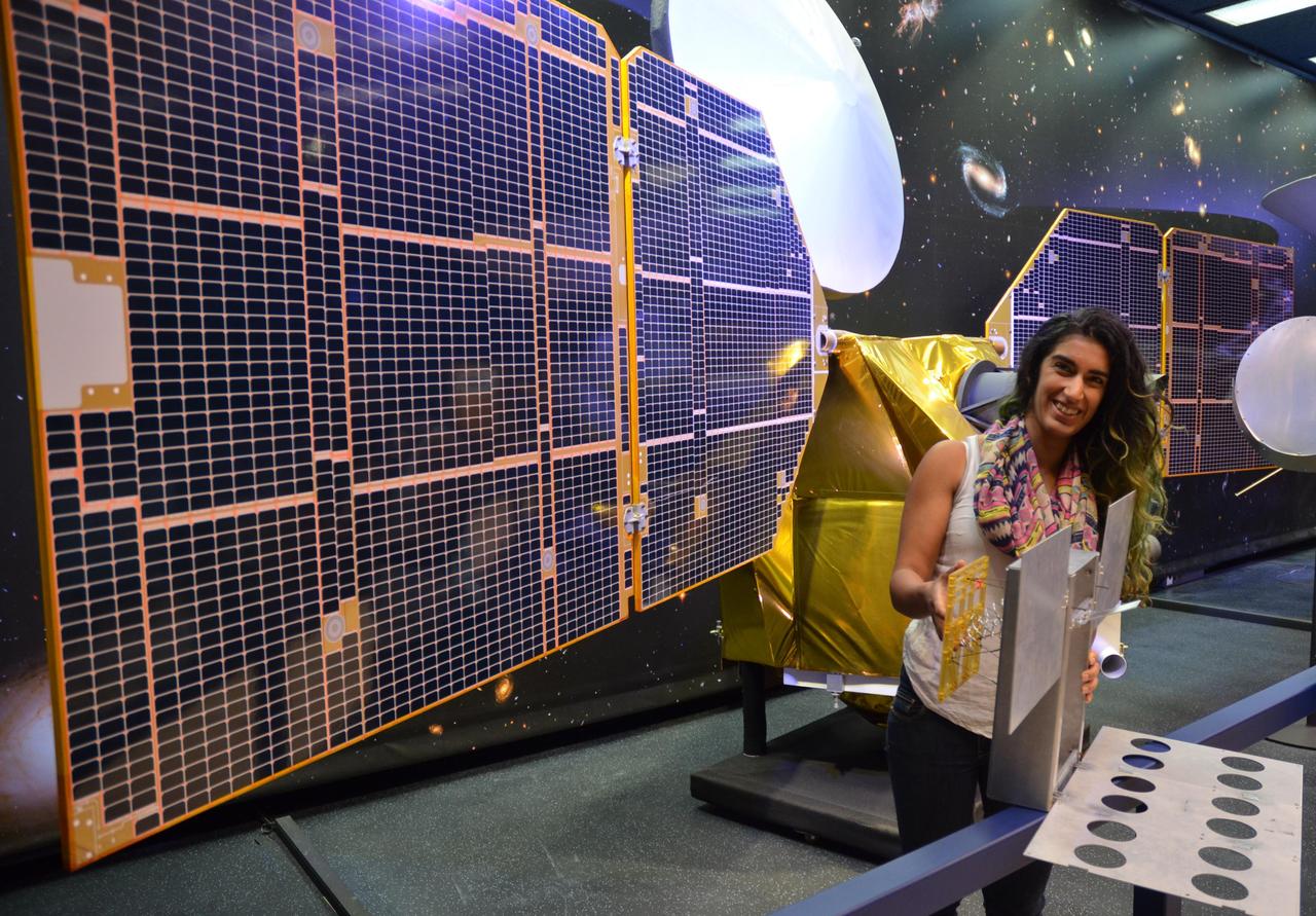
The full-scale mock-up of NASA's MarCO CubeSat held by Farah Alibay, a systems engineer at NASA's Jet Propulsion Laboratory, is dwarfed by the one-half-scale model of NASA's Mars Reconnaissance Orbiter behind her. MarCO, short for Mars Cube One, is the first interplanetary use of CubeSat technologies for small spacecraft. JPL is preparing two MarCO twins for launch in March 2016. They will ride along on an Atlas V launch vehicle lifting off from Vandenberg Air Force Base, California, with NASA's next Mars lander, InSight. MarCO is a technology demonstration aspect of the InSight mission. The mock-up in the photo is in a configuration to show the deployed position of components that correspond to MarCO's two solar panels and two antennas. During launch, those components will be stowed for a total vehicle size of about 14.4 inches (36.6 centimeters) by 9.5 inches (24.3 centimeters) by 4.6 inches (11.8 centimeters). After launch, the two MarCO CubeSats and InSight will be navigated separately to Mars. The MarCO twins will fly past the planet in September 2016 just as InSight is descending through the atmosphere and landing on the surface. MarCO is a technology demonstration to relay communications from InSight to Earth during InSight's descent and landing. InSight communications during that critical period will also be recorded by NASA's Mars Reconnaissance Orbiter for delayed transmission to Earth. InSight -- an acronym for Interior Exploration using Seismic Investigations, Geodesy and Heat Transport -- will study the interior of Mars to improve understanding of the processes that formed and shaped rocky planets, including Earth. Note: After thorough examination, NASA managers have decided to suspend the planned March 2016 launch of the Interior Exploration using Seismic Investigations Geodesy and Heat Transport (InSight) mission. The decision follows unsuccessful attempts to repair a leak in a section of the prime instrument in the science payload. http://photojournal.jpl.nasa.gov/catalog/PIA19671

Matthew Mullin and Bobby Meazell, Orbital ATK/Columbia Scientific Balloon Facility technicians, conduct compatibility testing on NASA Langley Research Center’s Radiation Dosimetry Experiment payload Wednesday, Sept. 9, at Fort Sumner, N.M. The successful compatibility test was a key milestone in ensuring the flight readiness of RaD-X, which is scheduled to launch on an 11-million-cubic-foot NASA scientific balloon no earlier than Friday, Sept. 11, from the agency’s balloon launching facility in Fort Sumner. RaD-X will measure cosmic ray energy at two separate altitude regions in the stratosphere—above 110,000 feet and between 69,000 to 88,500 feet. The data is key to confirming Langley’s Nowcast of Atmospheric Ionizing Radiation for Aviation Safety (NAIRAS) model, which is a physics-based model that determines solar radiation and galactic cosmic ray exposure globally in real-time. The NAIRAS modeling tool will be used to help enhance aircraft safety as well as safety procedures for the International Space Station. In addition to the primary payload, 100 small student experiments will fly on the RaD-X mission as part of the Cubes in Space program. The program provides 11- to 18-year-old middle and high school students a no-cost opportunity to design and compete to launch an experiment into space or into the near-space environment. The cubes measure just 4 centimeters by 4 centimeters. NASA’s scientific balloons offer low-cost, near-space access for scientific payloads weighing up to 8,000 pounds for conducting scientific investigations in fields such as astrophysics, heliophysics and atmospheric research. NASA’s Wallops Flight Facility in Virginia manages the agency’s scientific balloon program with 10 to 15 flights each year from launch sites worldwide. Orbital ATK provides program management, mission planning, engineering services and field operations for NASA’s scientific balloon program. The program is executed from the Columbia Scientific Balloon Facility in Palestine, Texas. The Columbia team has launched more than 1,700 scientific balloons in over 35 years of operation. Anyone may track the progress of the Fort Sumner flights, which includes a map showing the balloon’s real-time location, at: <a href="http://towerfts.csbf.nasa.gov/" rel="nofollow">towerfts.csbf.nasa.gov/</a> For more information on the balloon program, see: <a href="http://www.nasa.gov/scientificballoons" rel="nofollow">www.nasa.gov/scientificballoons</a> <b><a href="http://www.nasa.gov/audience/formedia/features/MP_Photo_Guidelines.html" rel="nofollow">NASA image use policy.</a></b> <b><a href="http://www.nasa.gov/centers/goddard/home/index.html" rel="nofollow">NASA Goddard Space Flight Center</a></b> enables NASA’s mission through four scientific endeavors: Earth Science, Heliophysics, Solar System Exploration, and Astrophysics. Goddard plays a leading role in NASA’s accomplishments by contributing compelling scientific knowledge to advance the Agency’s mission. <b>Follow us on <a href="http://twitter.com/NASAGoddardPix" rel="nofollow">Twitter</a></b> <b>Like us on <a href="http://www.facebook.com/pages/Greenbelt-MD/NASA-Goddard/395013845897?ref=tsd" rel="nofollow">Facebook</a></b> <b>Find us on <a href="http://instagrid.me/nasagoddard/?vm=grid" rel="nofollow">Instagram</a></b>

Photographs documenting International Space Station (ISS) Phase One activities at the Russian Space Agency's (RSA) Gagarin Cosmonaut Training Center, Korolov Mission Control Center and Zvezda; and ISS and Soyuz manufacturing at RSA's Khrunichev Design Center and RSC Energiya in Moscow, Russia, the French Space Agency's (CNES) INTESPACE facility in Toulouse, France, and the Italian Space Agency's (ASI) Alenia Spazio facility in Torino, Italy. Photographs were taken by Johnson Space Center Imagery and Publications Office contractors travelling from October 7 to November 4, 1996. Includes: VIEWS FROM RSC ENERGIYA'S SPACE MUSEUM: Room with a Buran model and photographic displays (17372-374). Salyut Space Station mock-up (17376). Russian propulsion engines on display (17377-378). Russian spacecraft on display (17375, 17387-398). Graphic displays (17399-405). VIEWS FROM RSC ENERGIYA MANUFACTURING FACILITIES: Unidentified facility (17379). Mir 24 crew member Michael C. Foale, suited in a Soyuz pressure suit, ingresses the Soyuz TM-26 flight article at RSC Energiya for a fit check (17380-381). Closeups of Foale inside the Soyuz during the fit check (17382-383, 17466-467). Overhead views of RSC Energiya's Building 444 manufacturing floor where docking modules and Soyuz TM spacecraft are built (17495-498). Technicians on the Building 444 manufacturing floor assembling probe and drogue docking modules (17499-500, 17504). Technicians assembling Soyuz spacecraft (17437-439). Views of other Soyuz spacecraft (17440-441). Androgynous Peripheral Docking System (APDS) mock-up (17501-503). Closeups of a control panel, possibly for the APDS mock-up (17519-528). VIEWS FROM ZVEZDA, RSA CONTRACTOR FOR SUIT DESIGN AND SOYUZ SEAT LINERS: Mir 24 crew member Foale dons a "penguin" flight suit for a fit check (17454-456). Zvezda personnel adjust Foale's Soyuz seat and seat liner (17442). Closeup of Foale, suited in a Soyuz pressure suit, sitting on a chair (17444). Zvezda personnel strap pressure-suited Foale into his Soyuz seat (17443, 17445, 17450). Views of Foale in his Soyuz seat during a pressurized pressure suit fit check (17451-453). Views looking into a vacuum chamber where Foale, wearing pressure suit, is strapped into his Soyuz seat (17466-467). Views of Zvezda personnel working at the vacuum chamber control station during the vacuum chamber suit test (17468-471). VIEWS FROM KHRUNICHEV DESIGN CENTER: Views of a green ISS Functional Cargo Block (FGB) test article on the manufacturing floor (17529, 17532-536, 17540-544). Views of an ISS Service Module (SM) test article on the manufacturing floor (17530-531, 17537, 17539). Closeup of the SM test article docking sphere (17538). Views of the FGB flight article on the manufacturing floor during systems tests (17545-548, 17550-567). Views of technicians conducting the FGB systems tests (17549, 17557). VIEWS FROM GAGARIN COSMONAUT TRAINING CENTER: NASA astronauts work out in the cosmonaut gym at Gagarin: Closeup of ISS 2R Expedition Commander William Shepherd on a weight machine (17384). Shepherd and an unidentified man with back to camera work out with dumbbells (17386). Shepherd does pull-ups (17447). Closeup of Foale on an exercise machine (17385). Closeups of Foale exercising arms on a cycle ergometer and a weight machine (17415, 17448-449). Foale exercises on a Nordic Track (17416). Closeup of Mir 23 crew member Jerry Linenger exercising arms (17417). Wendy Lawrence exercises with dumbbells (17418). Closeup of Lawrence in a handstand position (17419). David Wolf works out on a leg press machine (17446). Views of the Mir Space Station mock-up at Gagarin: Interior views of the Mir Base Module mock-up looking toward the transfer compartment (17421-425). Mir Base Module living area mock-up (17420). Overall views of the Base Module mock-up central control station (17426-427, 17505). Closeups of switch panels on the central control station (17428-436, 17506-518). Other views from Gagarin: Personnel work at an unidentified test/trainer control station (17472-473). Linenger sits at a table next to an RSA trainer during a Mir 23 meeting (17475-476). Out-of-focus view of two subjects in the Soyuz trainer (17474). Foale examines a Mir Complex EVA Suit (Orlan) with RSA trainers during an EVA suit training class (17492-494). VIEWS FROM KOROLOV MISSION CONTROL CENTER: Various views of personnel working in the NASA Consulting Room and/or PAO Consulting Room at Korolov Mission Control Center (17457-463). VIEWS FROM INTESPACE: Exterior views of an ISS Mini Pressurized Logistics Module (MPLM) structural test article (STA) during testing at INTESPACE (17406-409, 17477, 17482-484). Technicians install hatch on the MPLM STA (17410-414). Interior views of the MPLM STA (17478-481). VIEWS FROM ALENIA SPAZIO: Closeups of MPLM flight article #1 side panels during milling and refining at Alenia Spazio (17485-488). Workers process MPLM parts at milling machines (17489-491).