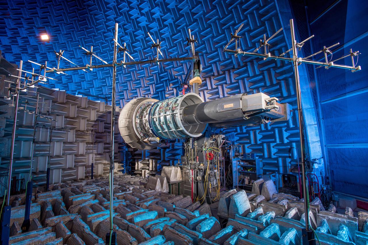
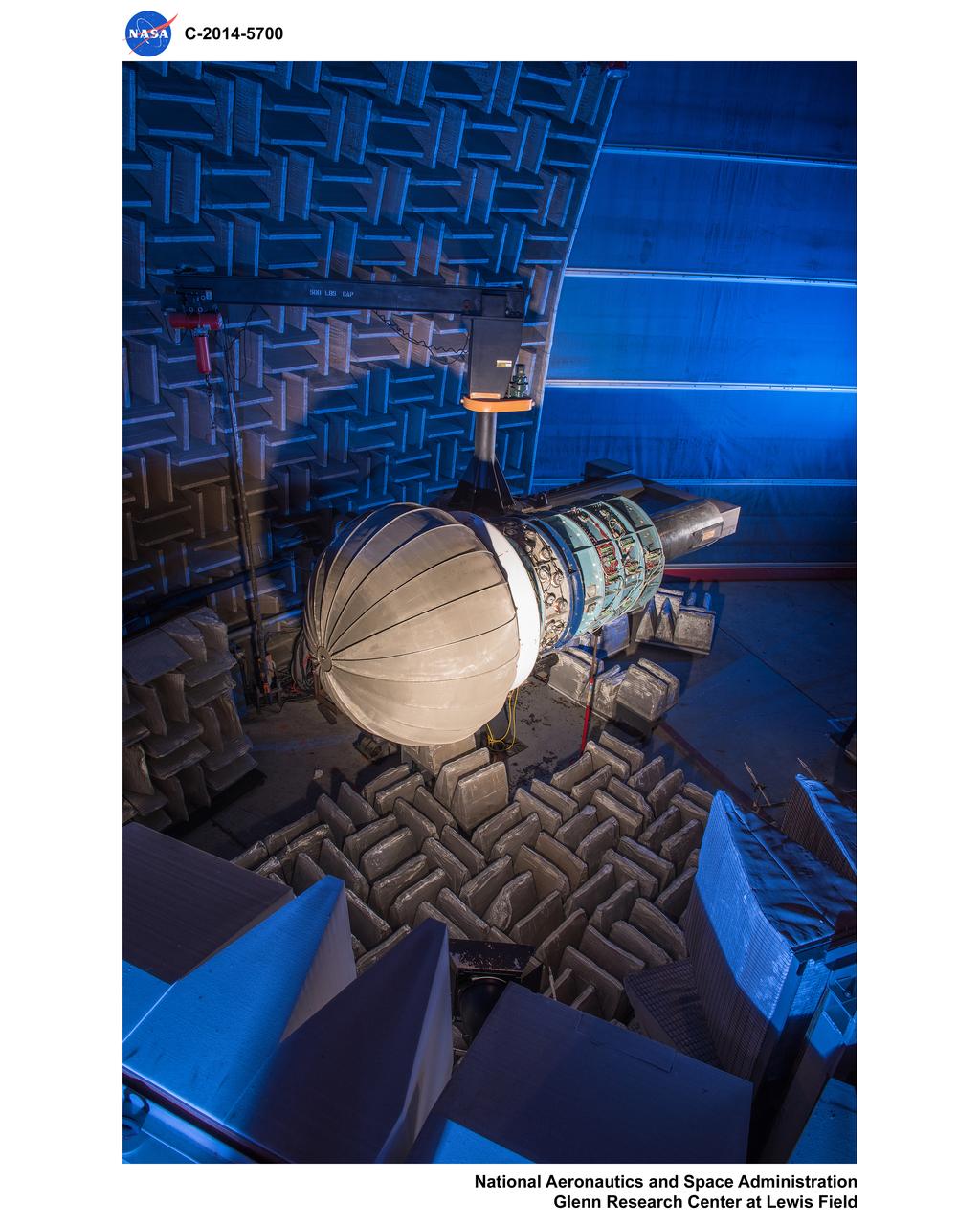
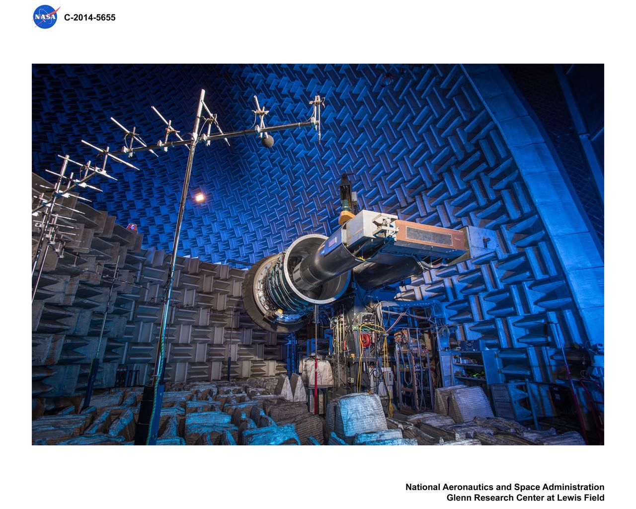
The Advanced Noise Control Fan shown here is located in NASA Glenn’s Aero-Acoustic Propulsion Laboratory. The 4-foot diameter fan is used to evaluate innovate aircraft engine noise reduction concepts less expensively and more quickly.
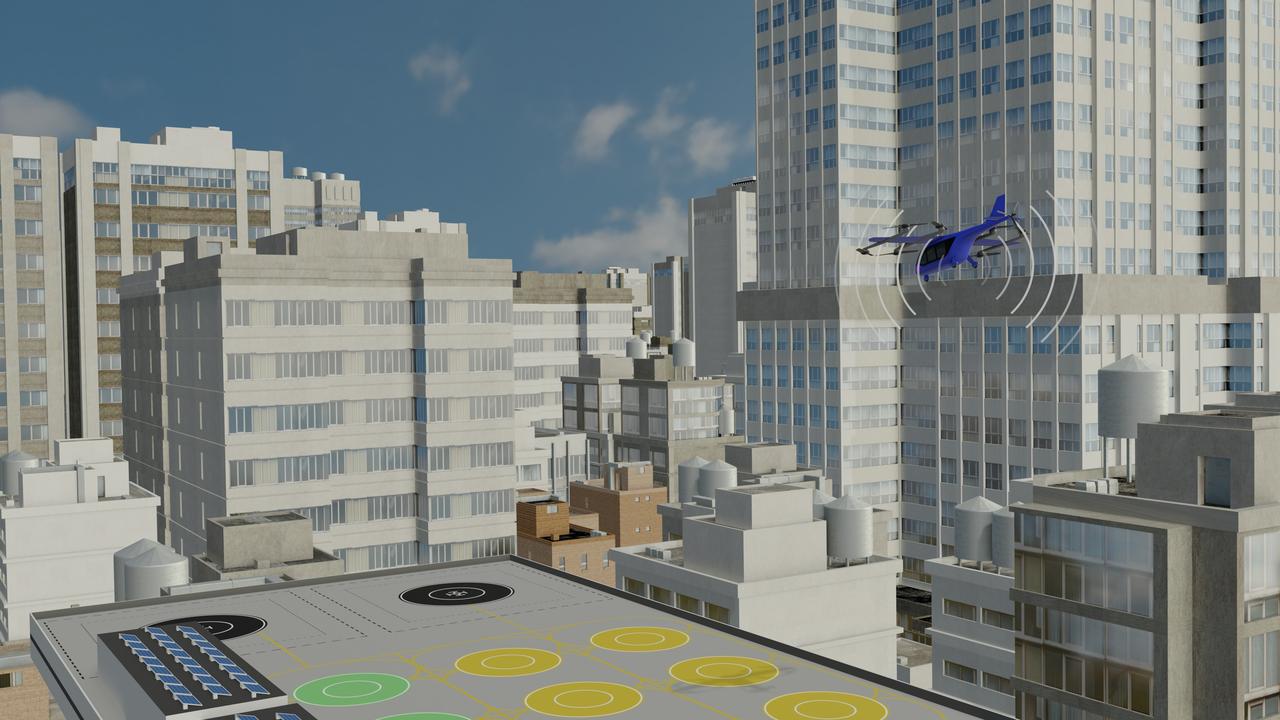
Several projects supporting NASA's Advanced Air Mobility, or AAM mission, are working on different elements to help make AAM a reality. One focus area is developing design tools manufacturers can use to reduce noise impacts.
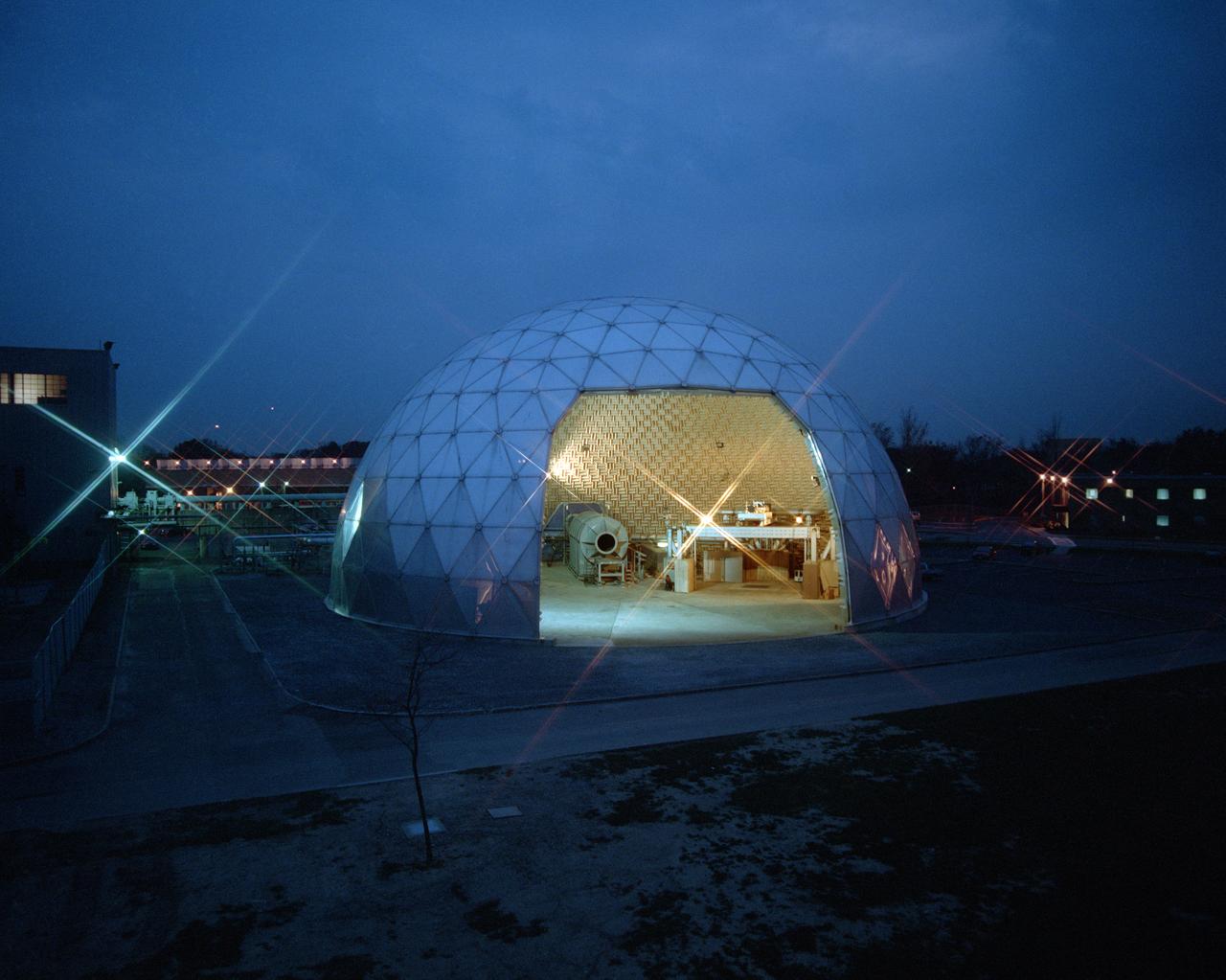
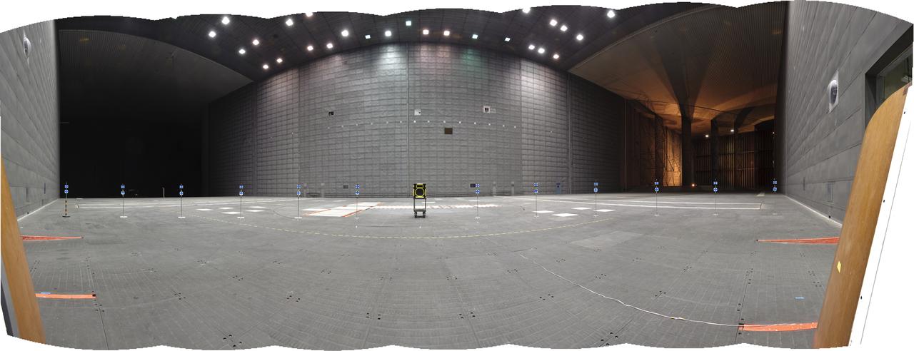
Modern jet engines are loud, but they used to be much louder. NASA’s Glenn Research Center has been at the forefront of the nation’s efforts to reduce aircraft engine noise for over 70 years. During this time, the center has built an array of test facilities to carry out this work, culminating in the Aero-Acoustic Propulsion Laboratory (AAPL), a world-class noise-reduction research facility. The AAPL, referred to as “the dome,” contains multiple test rigs enclosed in a large, echo-free chamber. The unique 130-foot diameter and 65-foot-high hemispherical structure stands out on Glenn’s campus. Its triangular sections make it appear like a golf ball rising from the ground. The interior is covered in spiky, fiberglass sound-dampening wedges and an overhead array of microphones that capture engine noise data.
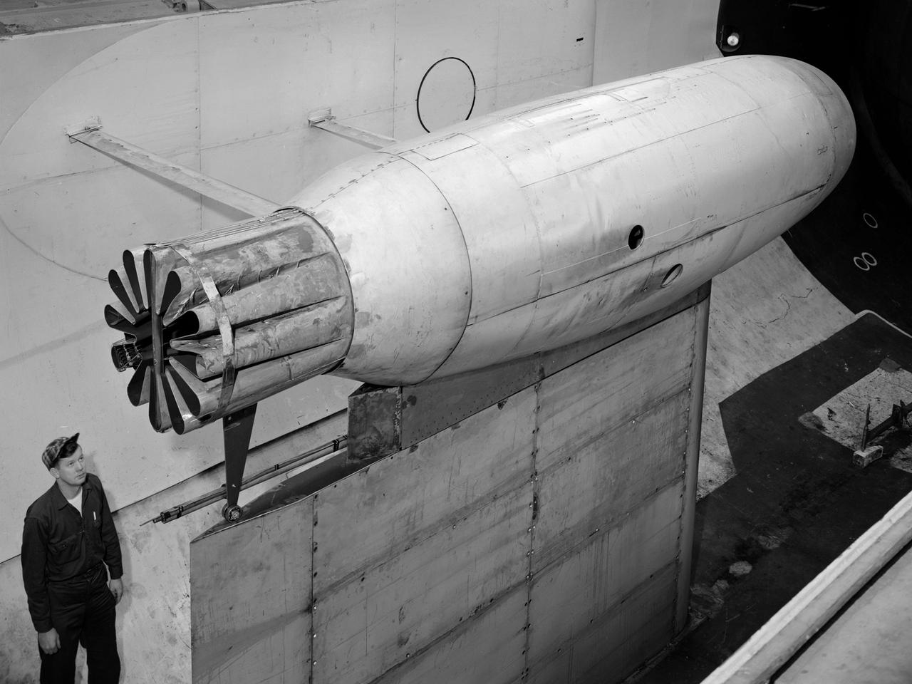
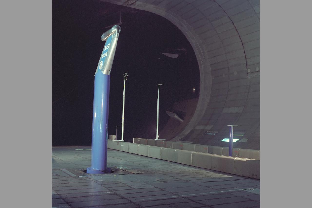
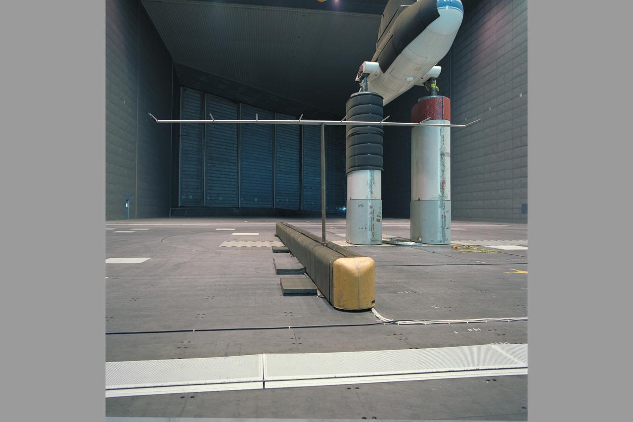
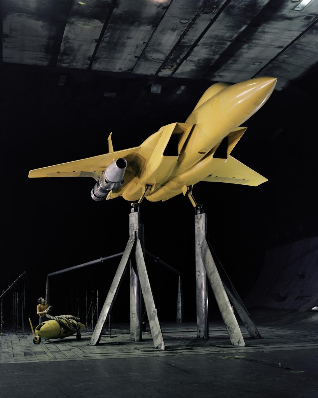
Horizontal view (side) of model, Ray Schmoranc in photo. Test #452
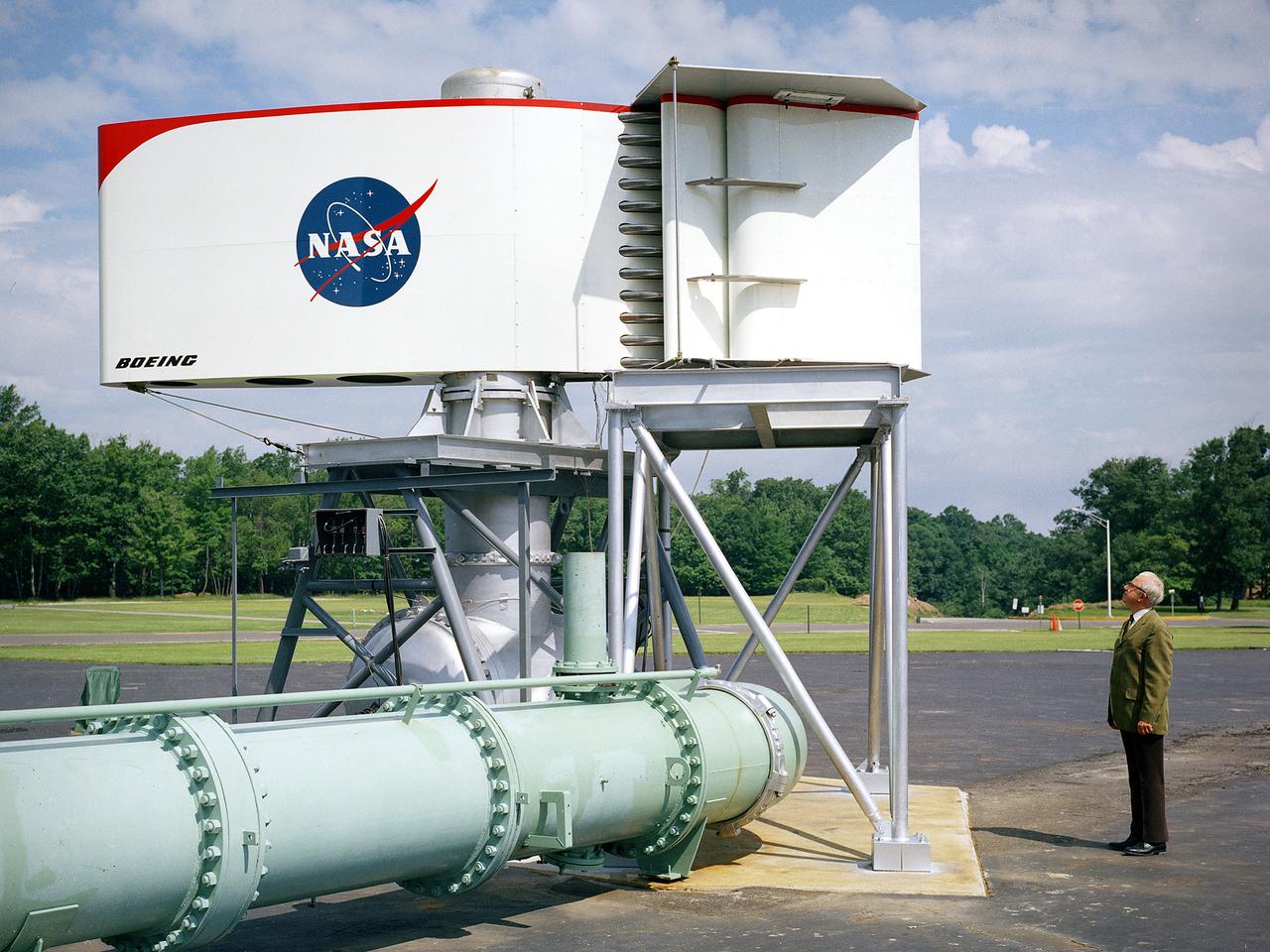
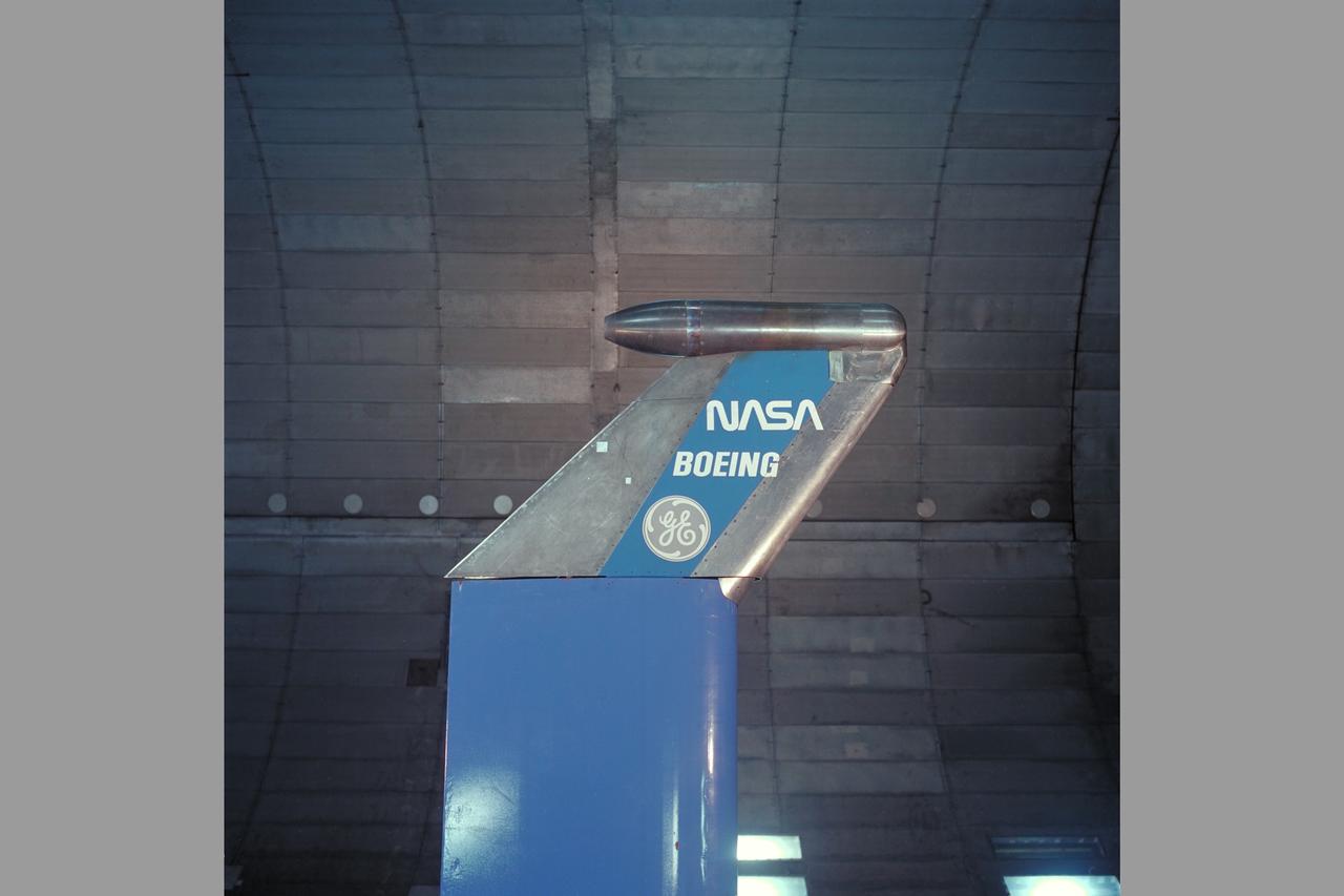
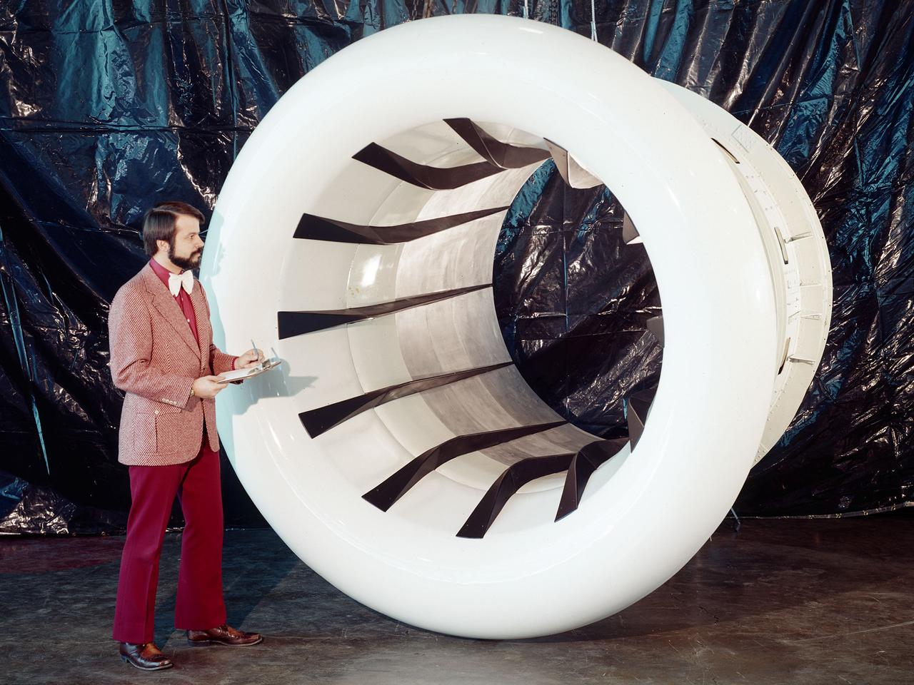
The Fan Noise Test Facility built at the Lewis Research Center to obtain far-field noise data for the National Aeronautics and Space Administration (NASA) and General Electric Quiet Engine Program. The engine incorporated existing noise reduction methods into an engine of similar power to those that propelled the Boeing 707 or McDonnell-Douglas DC-8 airliner. The new the low-bypass ratio turbofan engines of the 1960s were inherently quieter than their turbojet counterparts, researchers had a better grasp of the noise generation problem, and new acoustic technologies had emerged. Lewis contracted General Electric in 1969 to build and aerodynamically test three experimental engines with 72-inch diameter fans. The engines were then brought to Lewis and tested with an acoustically treated nacelle. This Fan Noise Test Facility was built off of the 10- by 10-Foot Supersonic Wind Tunnel’s Main Compressor and Drive Building. Lewis researchers were able to isolate the fan’s noise during these initial tests by removing the core of the engine. The Lewis test rig drove engines to takeoff tip speeds of 1160 feet per second. The facility was later used to test a series of full-scale model fans and fan noise suppressors to be used with the quiet engine. NASA researchers predicted low-speed single-stage fans without inlet guide vanes and with large spacing between rotors and stators would be quieter. General Electric modified a TF39 turbofan engine by removing the the outer protion of the fan and spacing the blade rows of the inner portion. The tests revealed that the untreated version of the engine generated less noise than was anticipated, and the acoustically treated nacelle substantially reduced engine noise.
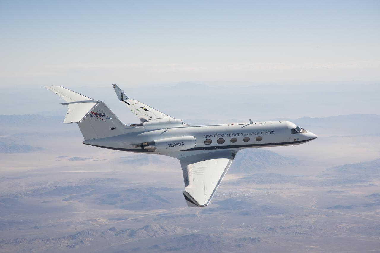
An Armstrong G-III aircraft carrying the Flexys© Adaptive Compliant Trailing Edge flap. The smooth transition between the flaps and wing reduced drag and noise.
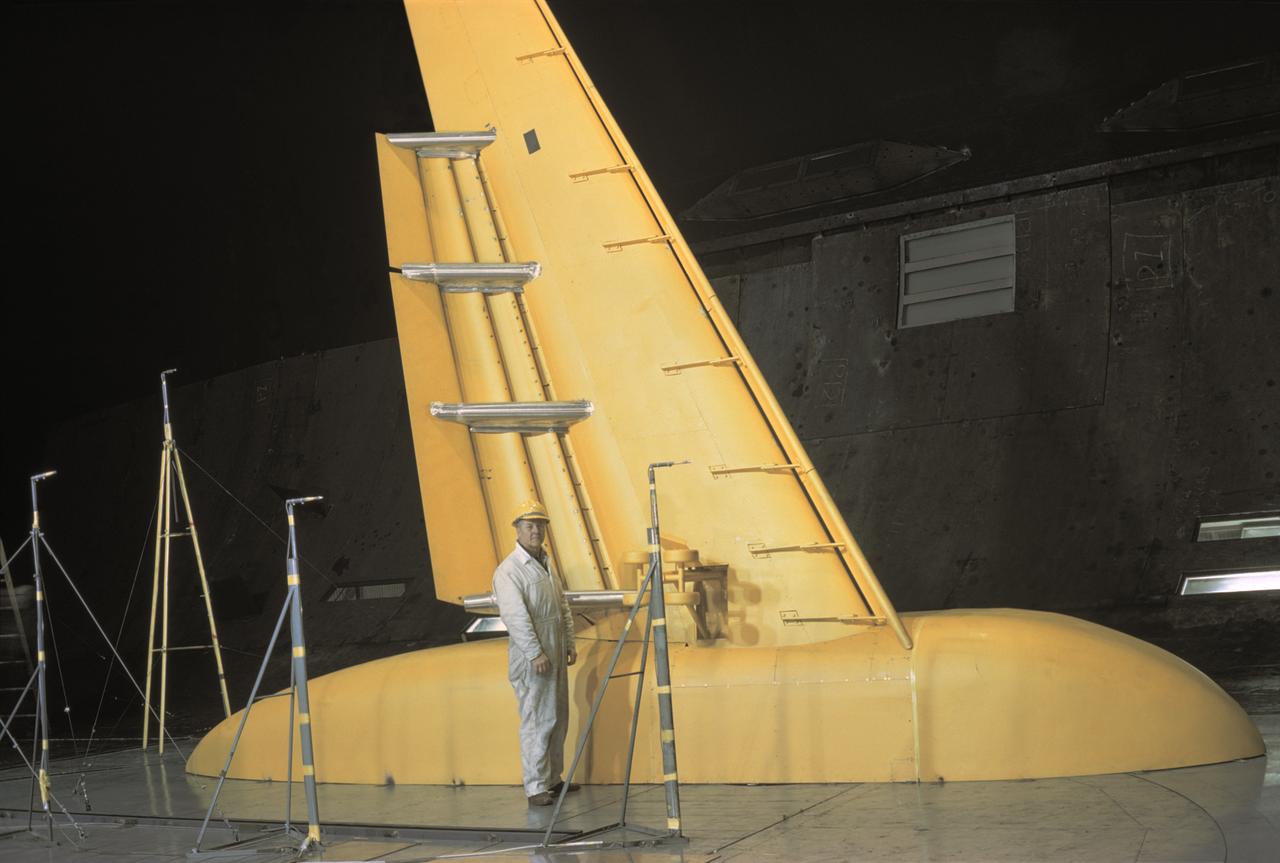
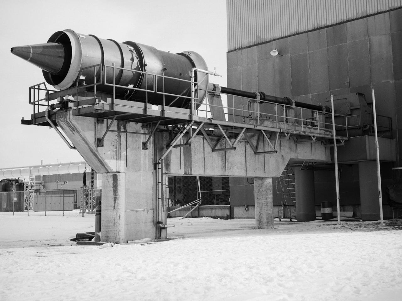
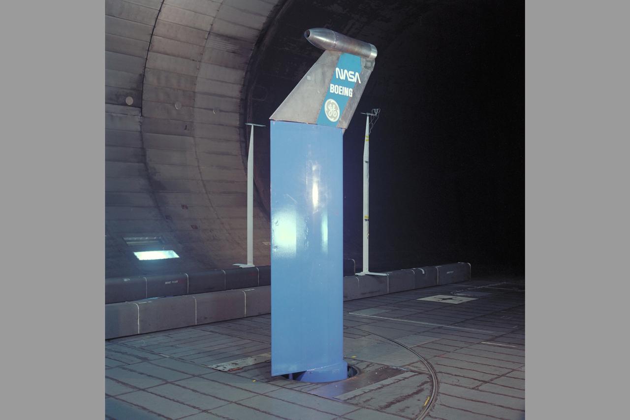
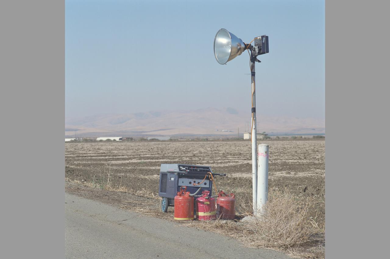
The augmentor wing concept was introduced during the early 1960s to enhance the performance of vertical and short takeoff (VSTOL) aircraft. The leading edge of the wing has full-span vertical flaps, and the trailing edge has double-slotted flaps. This provides aircraft with more control in takeoff and landing conditions. The augmentor wing also produced lower noise levels than other VSTOL designs. In the early 1970s Boeing Corporation built a Buffalo C-8A augmentor wing research aircraft for Ames Research Center. Researches at Lewis Research Center concentrated their efforts on reducing the noise levels of the wing. They initially used small-scale models to develop optimal nozzle screening methods. They then examined the nozzle designs on a large-scale model, seen here on an external test stand. This test stand included an airflow system, nozzle, the augmentor wing, and a muffler system below to reduce the atmospheric noise levels. The augmentor was lined with noise-reducing acoustic panels. The Lewis researchers were able to adjust the airflow to simulate conditions at takeoff and landing. Once the conditions were stabilized they took noise measurements from microphones placed in all directions from the wing, including an aircraft flying over. They found that the results coincided with the earlier small-scale studies for landing situations but not takeoffs. The acoustic panels were found to be successful.
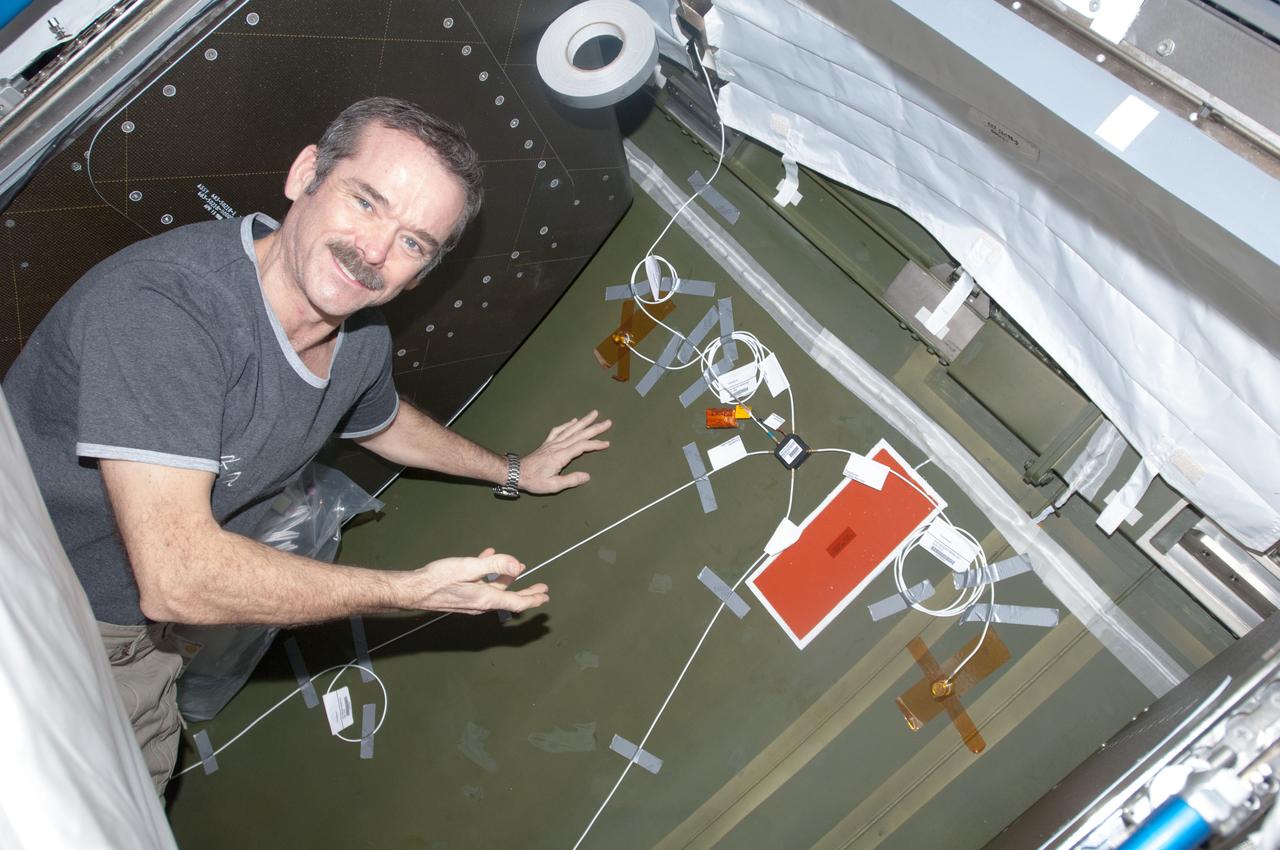
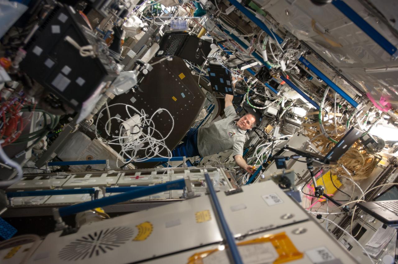
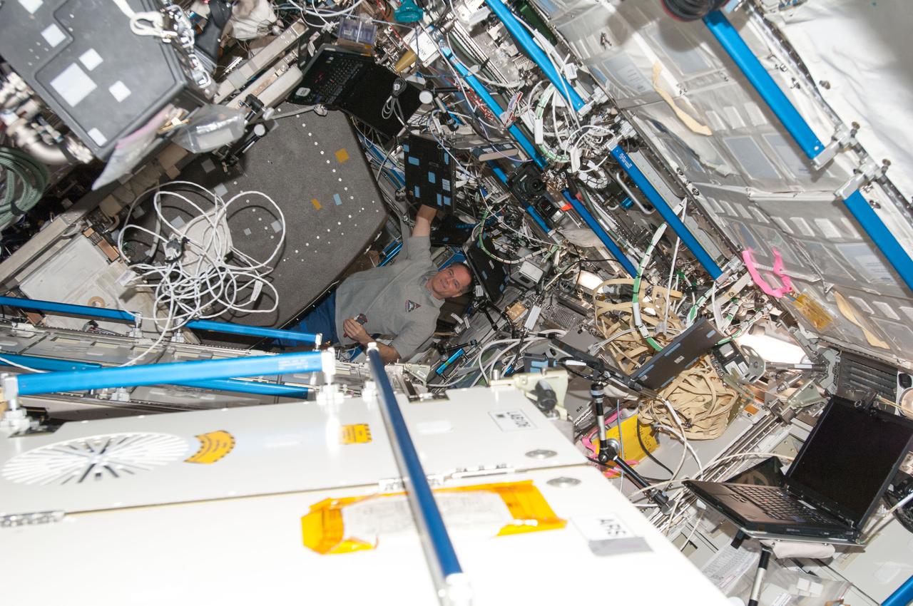
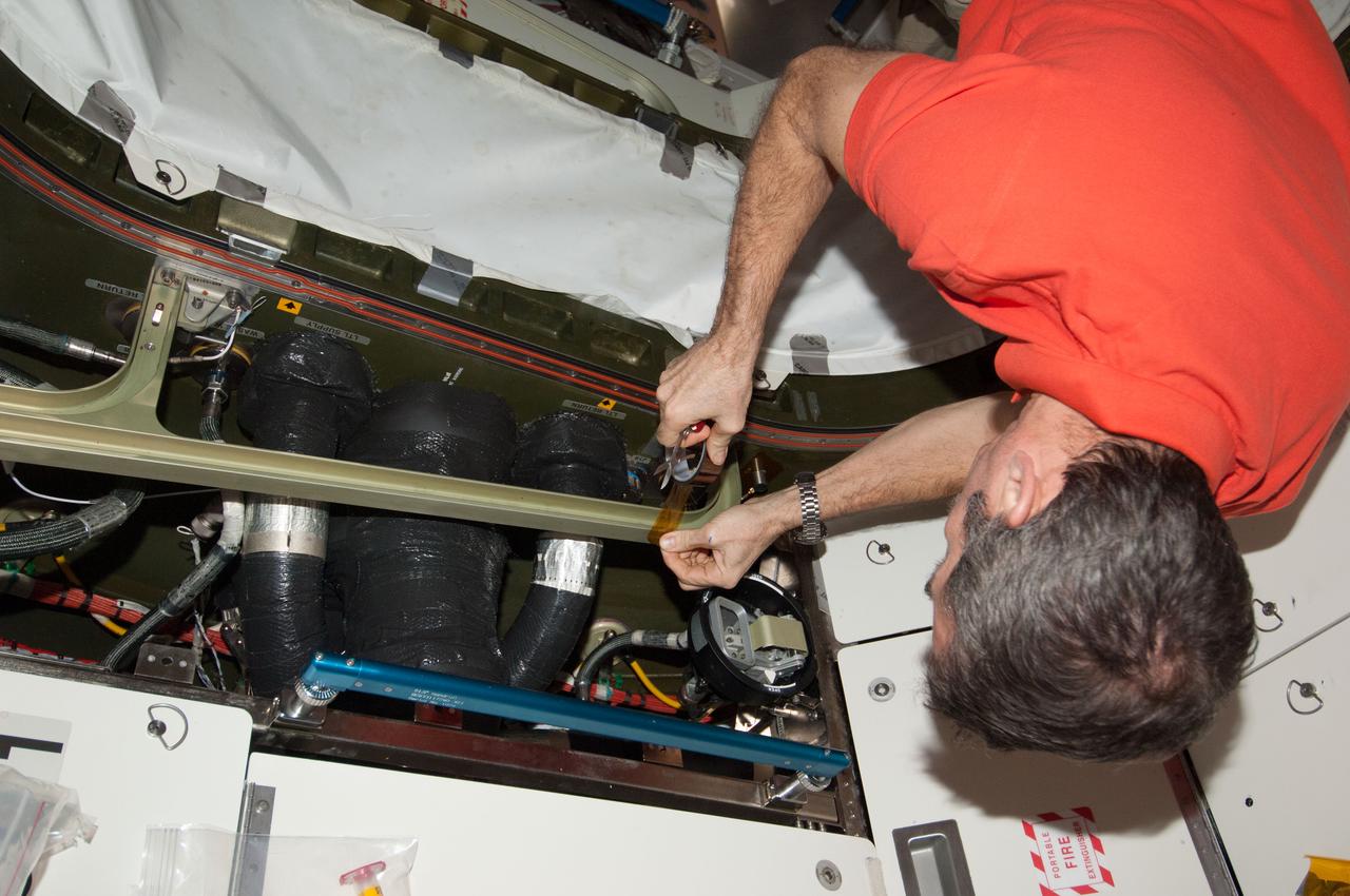
View of Canadian Space Agency (CSA) Chris Hadfield,Expedition 34 Flight Engineer (FE),installing Ultra-Sonic Background Noise Tests (UBNT) sensors behind rack in the U.S. Laboratory using the International Space Station (ISS) as Testbed for Analog Research (ISTAR) procedures. These sensors detect high frequency noise levels generated by ISS hardware and equipment operating within the U.S. Laboratory. Photo was taken during Expedition 34.
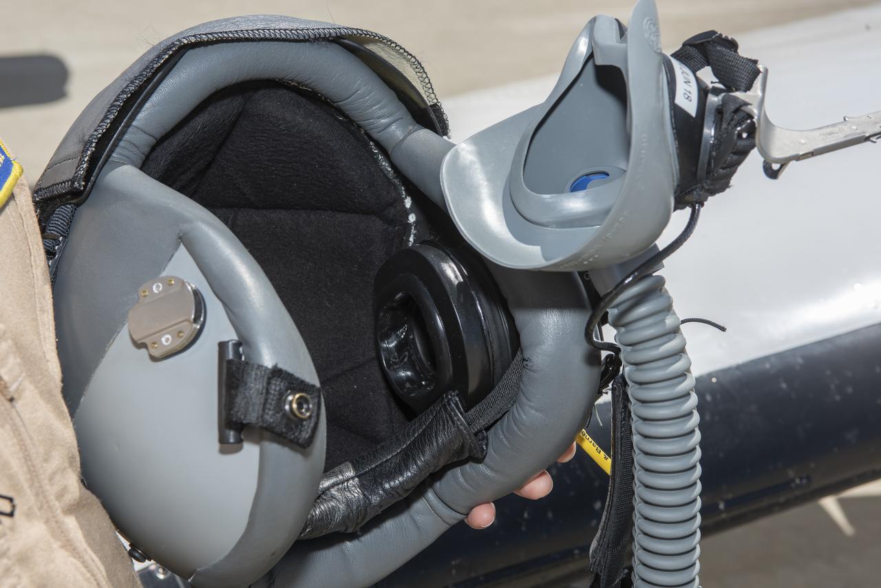
The black circle inside the helmet on the right contains some of the new elements of a noise reduction headphone that is part of an Active Noise Reduction system. It helps pilots hear better and improve communication during flight research missions.
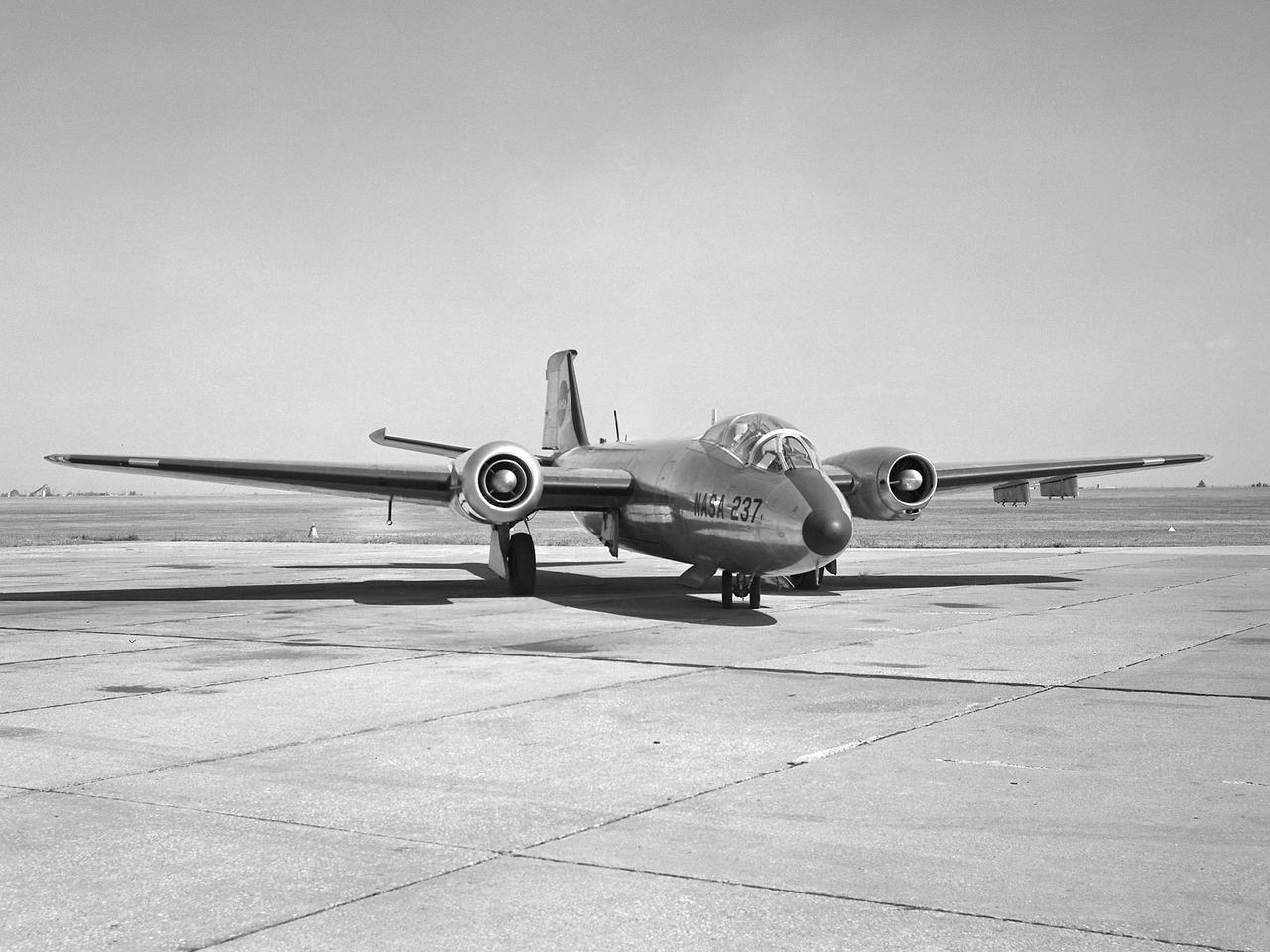
A Martin B-57B Canberra outfitted with a noise suppressor on its right engine at the National Aeronautics and Space Administration (NASA) Lewis Research Center. The aircraft was being prepared for the October 1966 Inspection of the center. The Inspection also marked Lewis’ twentieth anniversary. Lewis researchers had been studying engine noise for almost a decade, but the problem seemed to be increasing in the mid-1960s with heavier airline traffic and larger engines. Researchers discovered early on that the majority of the noise did not emanate from the engine itself, but from the mixing of the hot exhaust gasses with the atmosphere. Attempts to reduce the turbulence using new exhaust nozzles were successful but often resulted in decreased engine performance. The researchers decided to try to lower the jet nozzle exit velocity without decreasing its thrust. The inlet mass air flow had to be increased to accomplish this. The Lewis B-57B was powered by two Wright Aeronautical J65 turbojets. Lewis engineers modified the stators on the two engines to simulate the noise levels from more-modern turbofan engines. A noise suppressor was added to only one of the two engines, seen here on the left. The engines were run one at a time at power levels similar to landing while the aircraft sat on the Lewis hangar apron. A microphone and recording equipment was setup to capture the noise levels. The engine with the suppressor produced 13 fewer decibels than the standard engine.
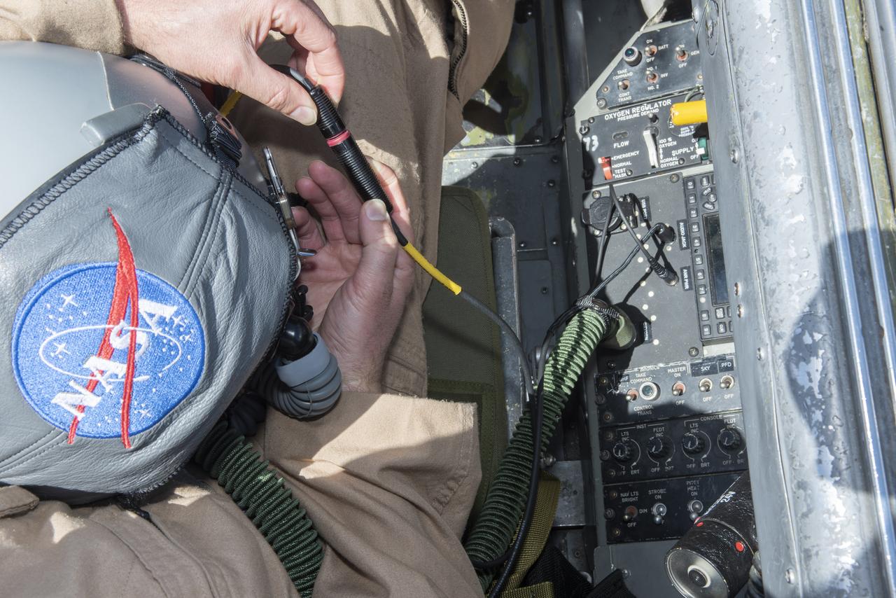
The new Active Noise Reduction system plugs directly from the helmet to a panel inside the aircraft.
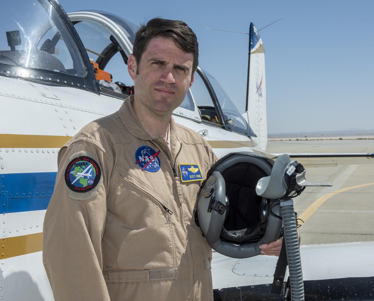
T-34 lead pilot Scott Howe said the new Active Noise Reduction system makes it easier to hear in the aircraft's loud cockpit.
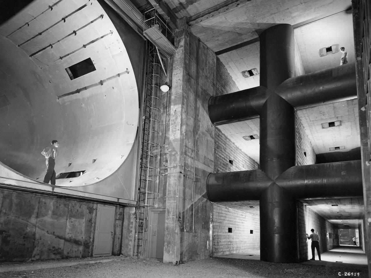
The 8- by 6-Foot Supersonic Wind Tunnel at the National Advisory Committee for Aeronautics (NACA) Lewis Flight Propulsion Laboratory was the largest supersonic wind tunnel in the nation at the time and the only one able to test full-scale engines at supersonic speeds. The 8- by 6 was designed as a non-return and open-throat tunnel. A large compressor created the air flow at one end of the tunnel, squeezed the flow to increase its velocity just before the test section, then reduced the velocity, and expelled it into the atmosphere at the other end of the tunnel. This design worked well for initial aerodynamic testing, but the local community was literally rattled by the noise and vibrations when researchers began running engines in the test section in January 1950. The NACA’s most modern wind tunnel was referred to as “an 87,000-horsepower bugle aimed at the heart of Cleveland.” NACA Lewis responded to the complaints by adding an acoustic housing at the end of the tunnel to dampen the noise. The structure included resonator chambers and a reinforced concrete muffler structure. Modifications continued over the years. A return leg was added, and a second test section, 9 -by 15-foot, was incorporated in the return leg in the 1960s. Since its initial operation in 1948, the 8- by 6-foot tunnel has been aggressively used to support the nation's aeronautics and space programs for the military, industry, and academia.
A ghostly view of Enceladus reveals the specter of the moon icy plume of fine particles. Scientists continue to monitor the plume, where mission planning allows, using the Cassini spacecraft imaging cameras
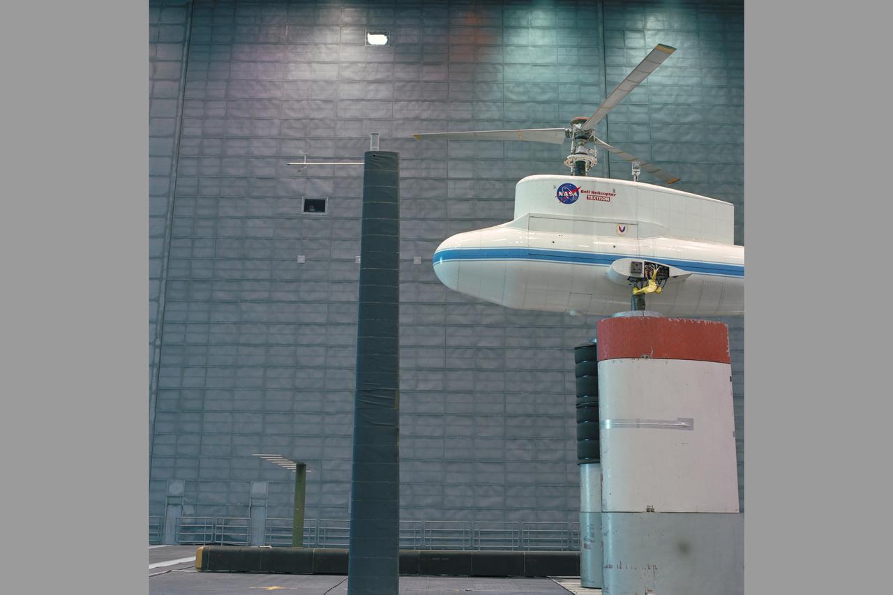
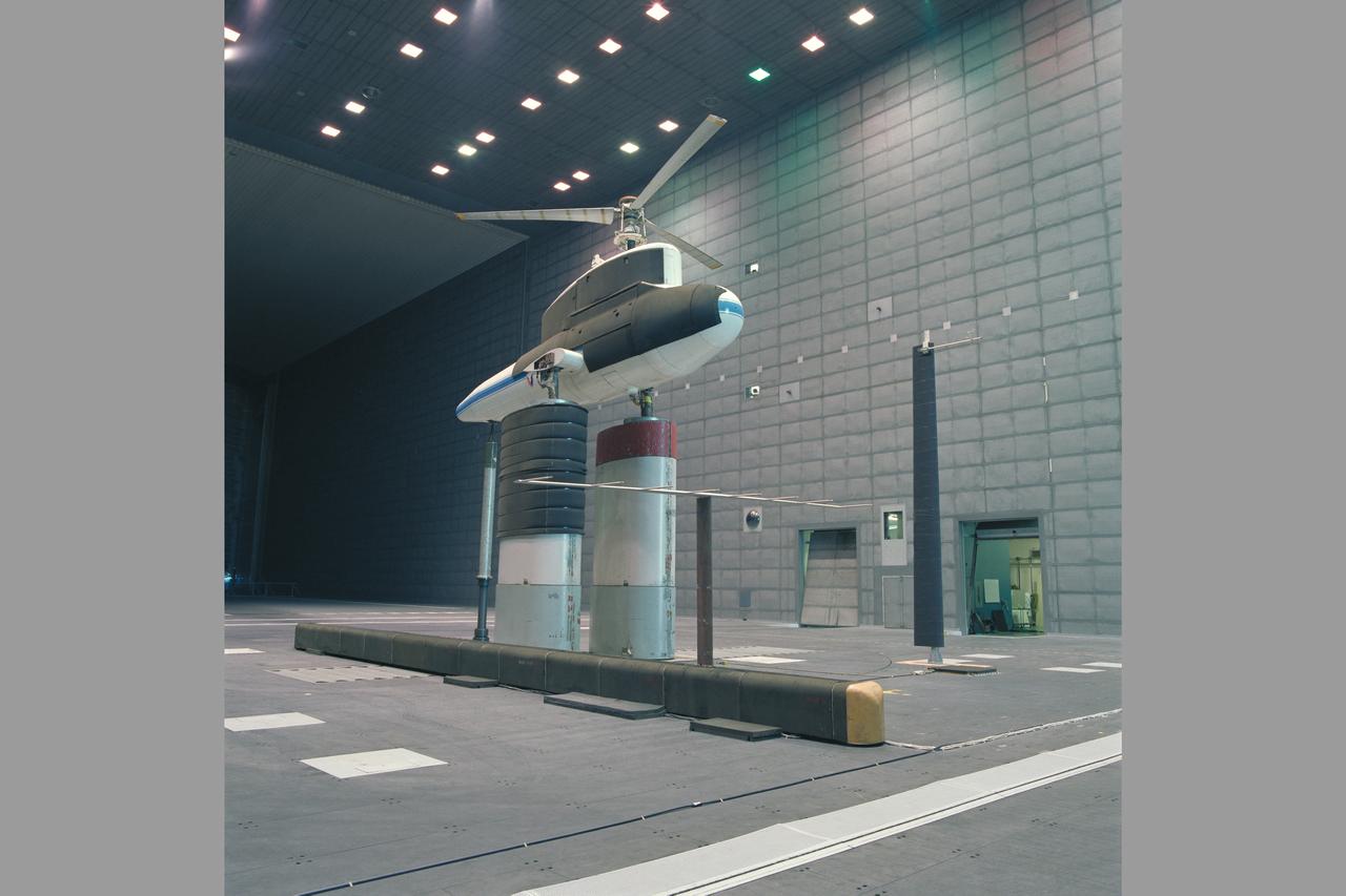
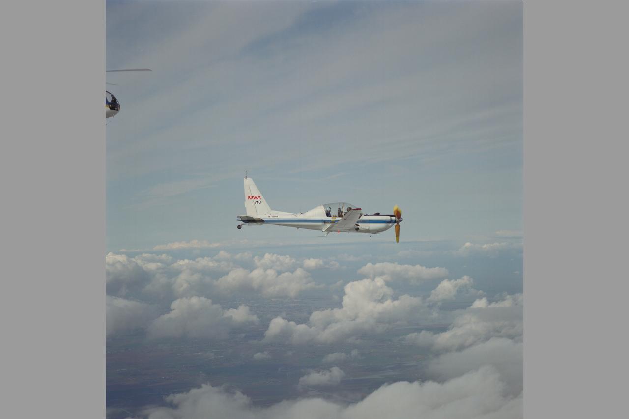
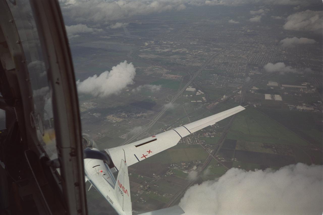
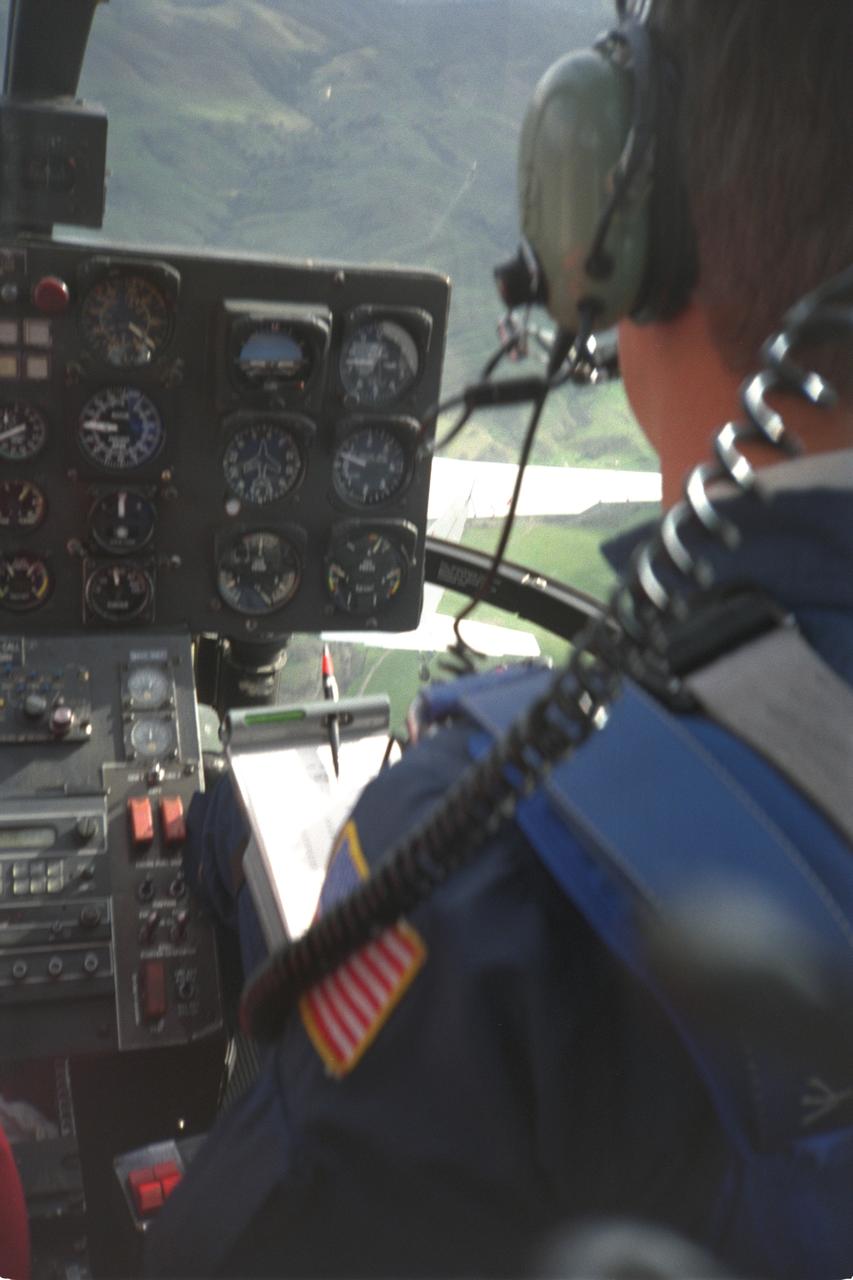
YO-3A (NASA-718) Flying Acoustic Platform: The Quiet Plane is used as a flying microphone platform to study aircraft noise, especially helicopter noise.
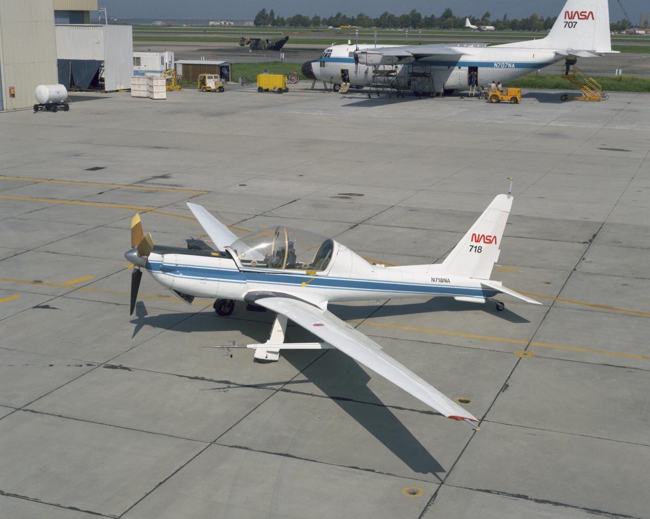
YO-3A Quiet Plane (NASA-718) parked on ramp This aircraft is a flying acoustic platform used as a microphone to study aircraft noise, especially helicopter noise.
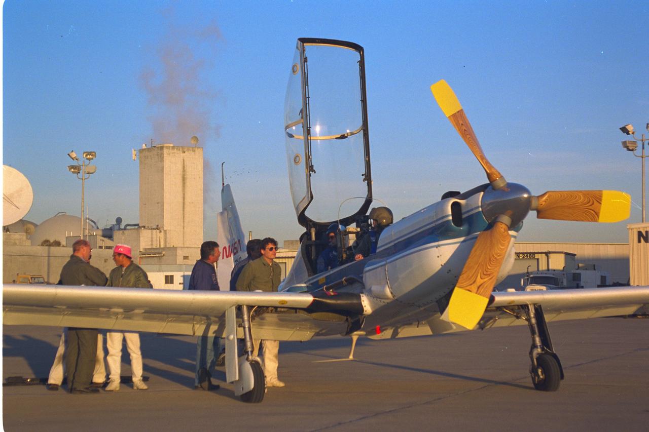
YO-3A (NASA-718) Flying Acoustic Platform: The Quiet Plane is used as a flying microphone platform to study aircraft noise, especially helicopter noise.
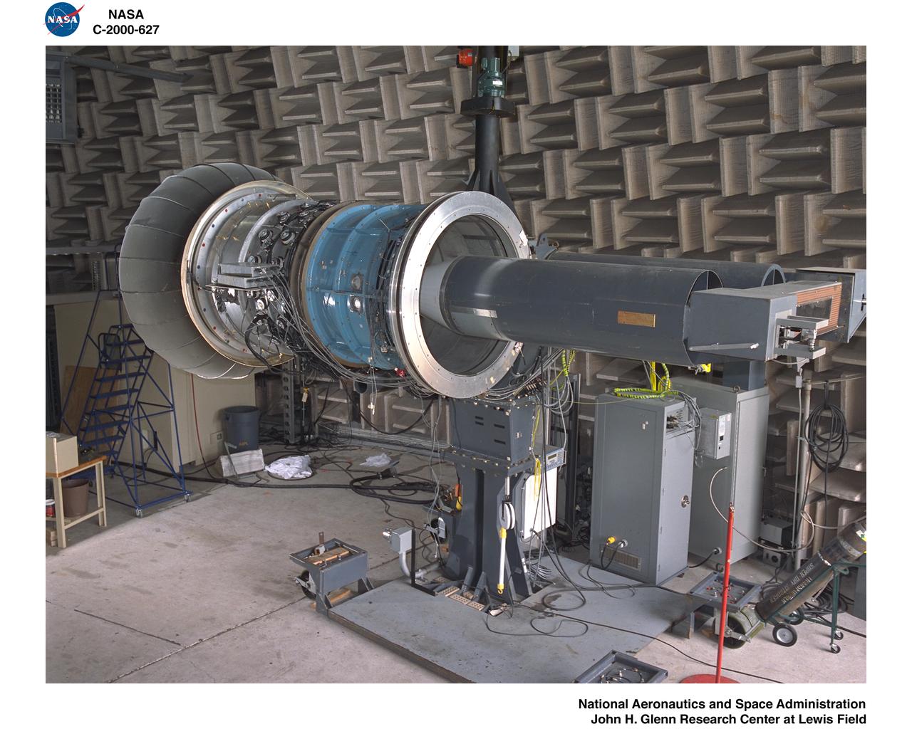
ACTIVE NOISE CONTROL FAN
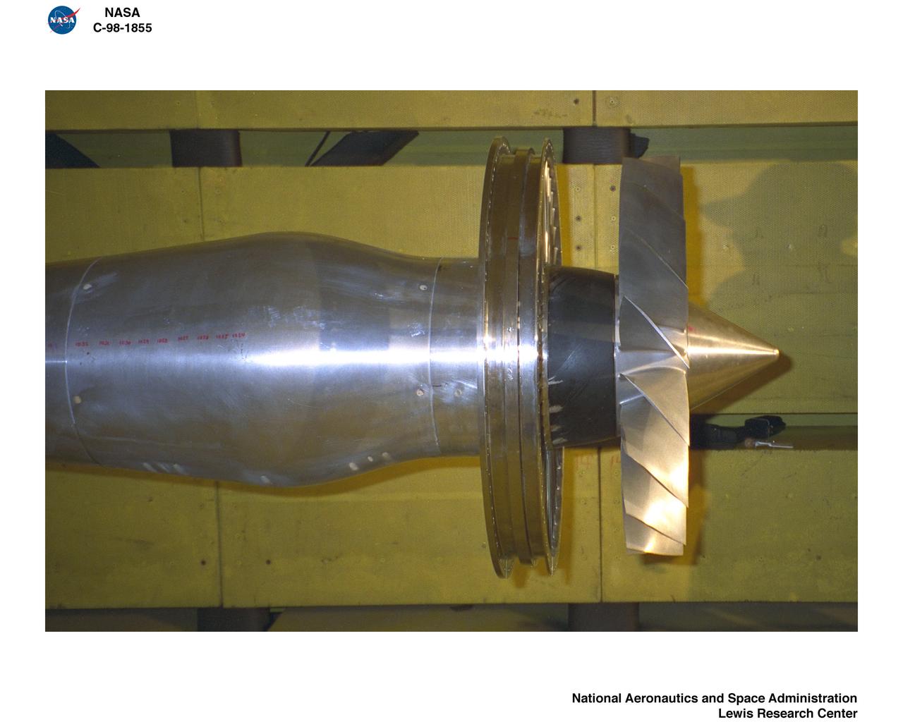
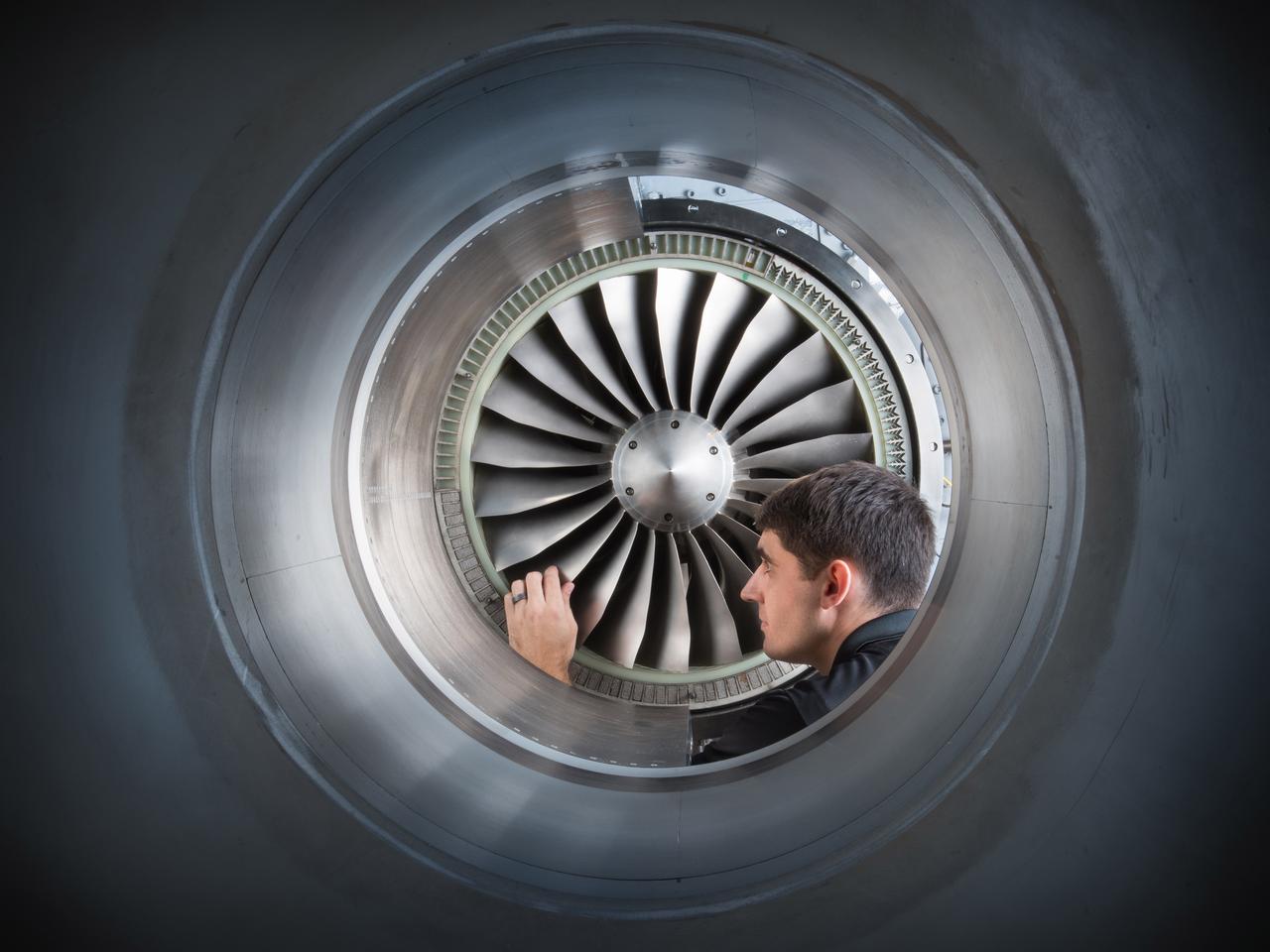
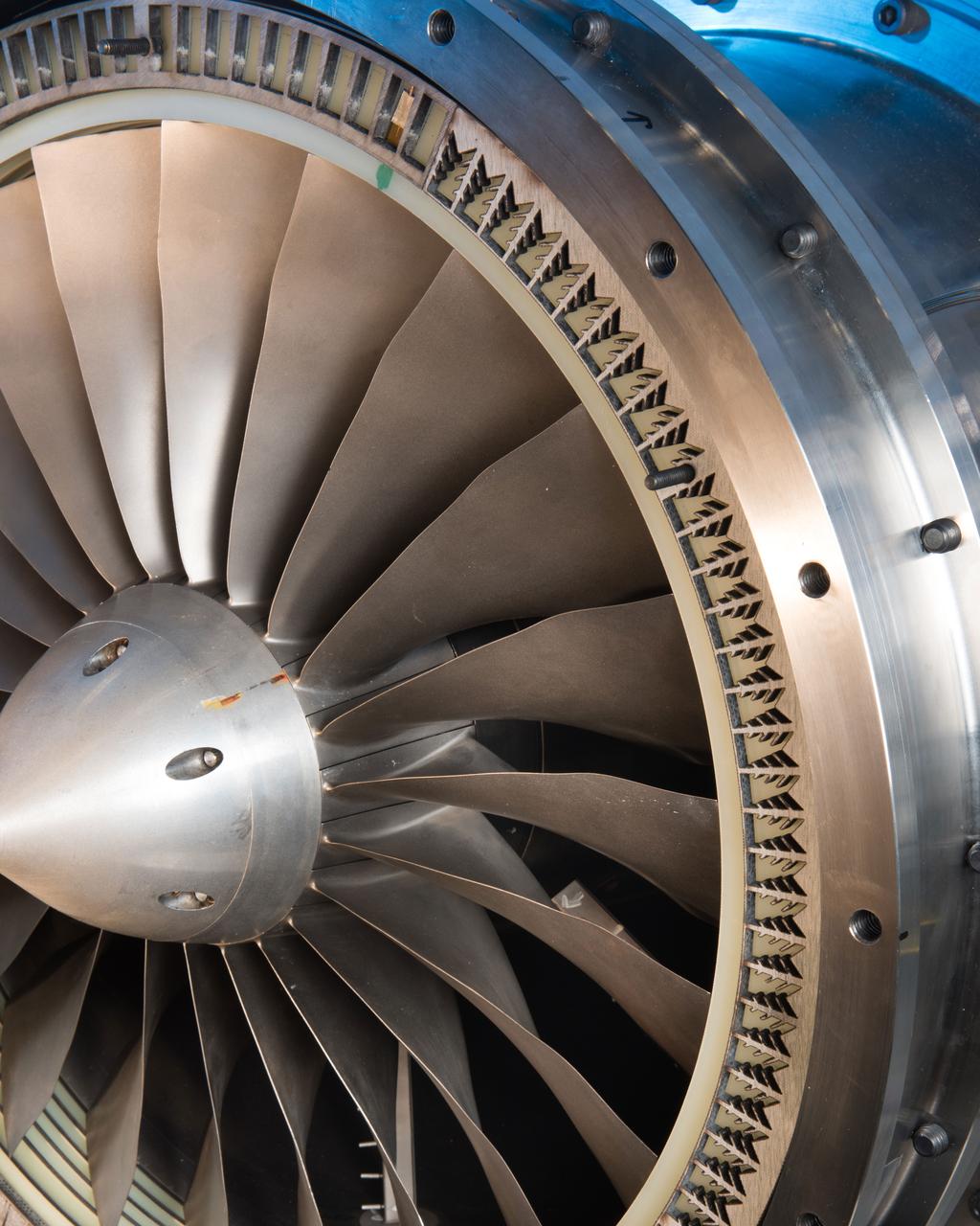
ALLISON LOW NOISE FAN
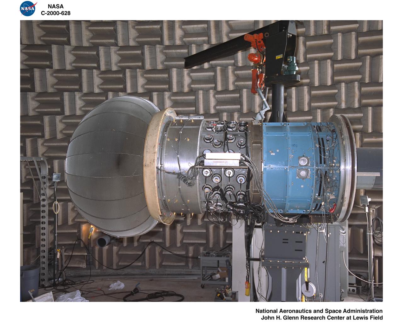
ACTIVE NOISE CONTROL FAN
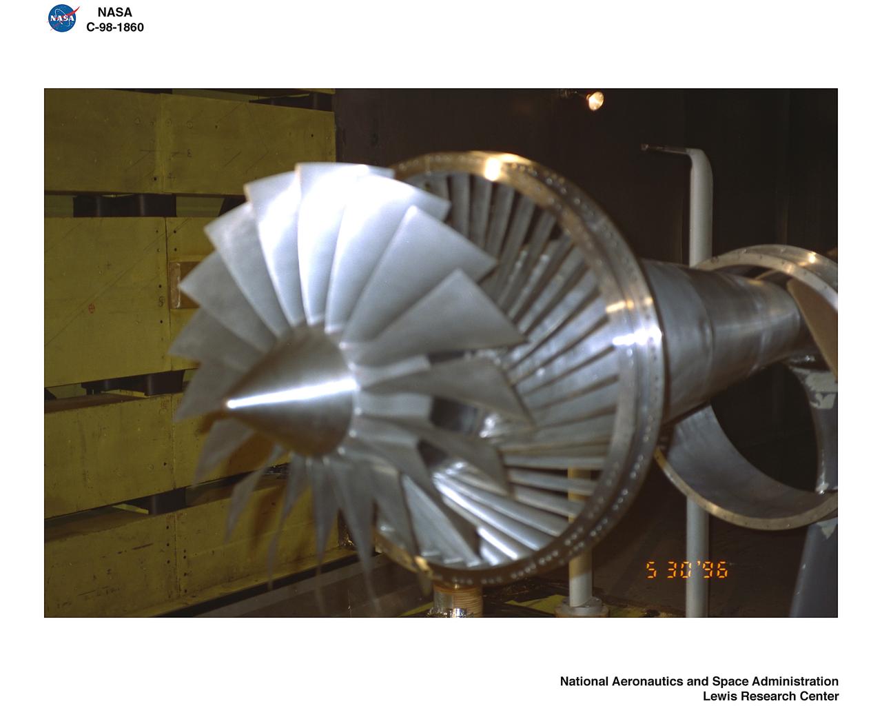
ALLISON LOW NOISE FAN
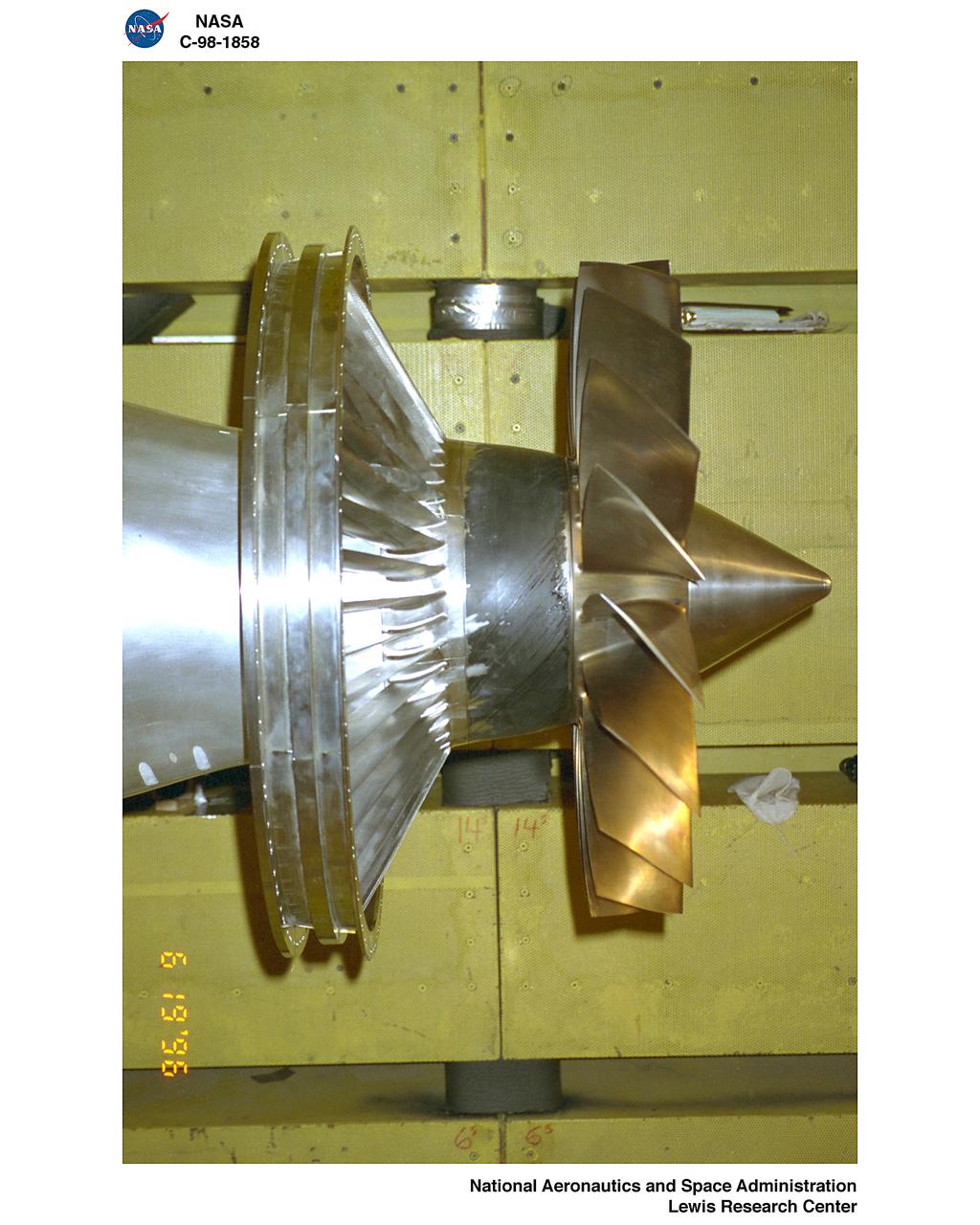
ALLISON LOW NOISE FAN
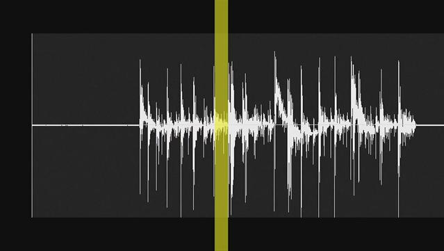
This video demonstrates the hiss-like radio noise generated by electrons moving along magnetic field lines from the Saturnian moon Enceladus to a glowing patch of ultraviolet light on Saturn.
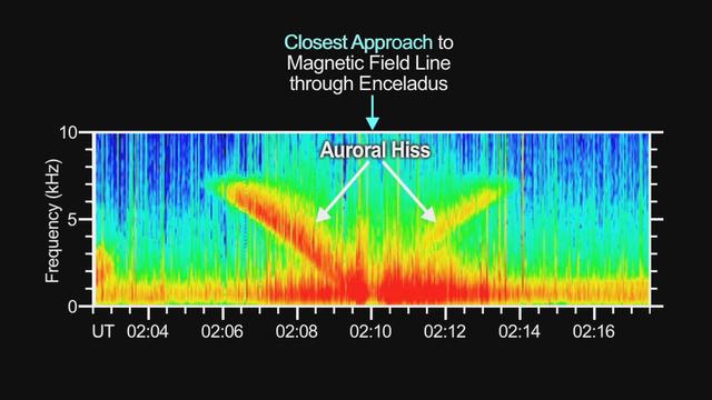
This graphic demonstrates the hiss-like radio noise generated by electrons moving along magnetic field lines from the Saturnian moon Enceladus to a glowing patch of ultraviolet light on Saturn.
A Pratt and Whitney J57 engine is tested with a Greatex No.1 nozzle in the Altitude Wind Tunnel at the National Advisory Committee for Aeronautics (NACA) Lewis Flight Propulsion Laboratory. At the time the aircraft industry was preparing to introduce jet airliners to the nation’s airways. The noise produced by the large jet engines, however, posed a considerable problem for communities near airports. The NACA had formed a Special Subcommittee on Aircraft Noise to coordinate research on the issue. Preliminary tests showed that the source of the loudest noise was not the engine itself, but the mixing of the engine’s exhaust with the surrounding air in the atmosphere. The pressures resulting from this turbulence produced sound waves. Lewis researchers undertook a variety of noise-reduction studies involving engine design, throttling procedures, and noise suppressors. One of their first efforts focused on new types of nozzles to mix the exhaust with the surrounding air. The nozzles had a variety of shapes designed to slow down exhaust velocity before it combined with the air and thus decrease the noise. From January to May 1957 a Pratt and Whitney J57 engine was equipped with various shaped nozzles, as seen in this photograph, and run in simulated flight conditions in the Altitude Wind Tunnel. A number of nozzle configurations, including several multi-exit “organ pipe” designs, were created. It was found that the various nozzle types did reduce the noise levels, but they also reduced the aircraft’s thrust.
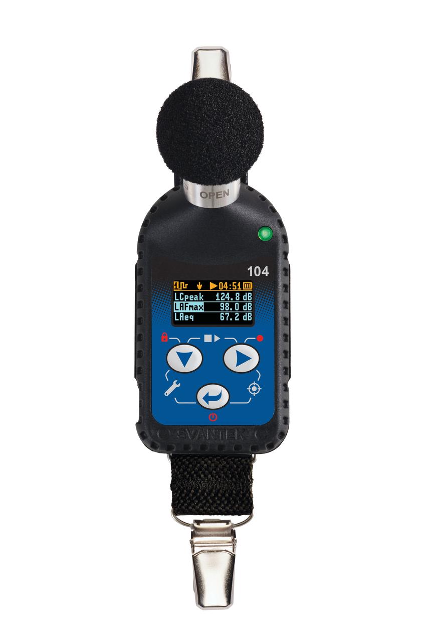
jsc2025e044837 2/19/2019) --- Shown is the SV104A noise dosimeter that measures noise dose and noise levels in the large measurement range of 55 dB to 140 dB aboard the International Space Station. This dosimeter is part of A Next Generation Crew Health & Performance Acoustic Monitoring Capability for Exploration: An International Space Station Technology Demonstration (Wireless Acoustics) investigation. Image courtesy of SVANTEK.
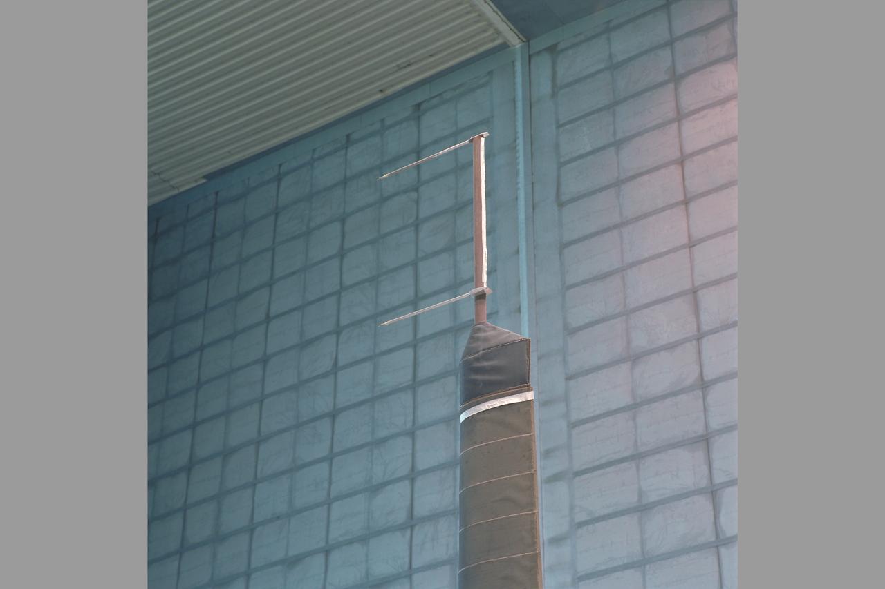
MD-900 (N900MH) Helicopter Noise Abatement Test - Crows Landing, Microphones
High Speed Research (HSR) Source Noise Test-592, 40x80ft w.t.
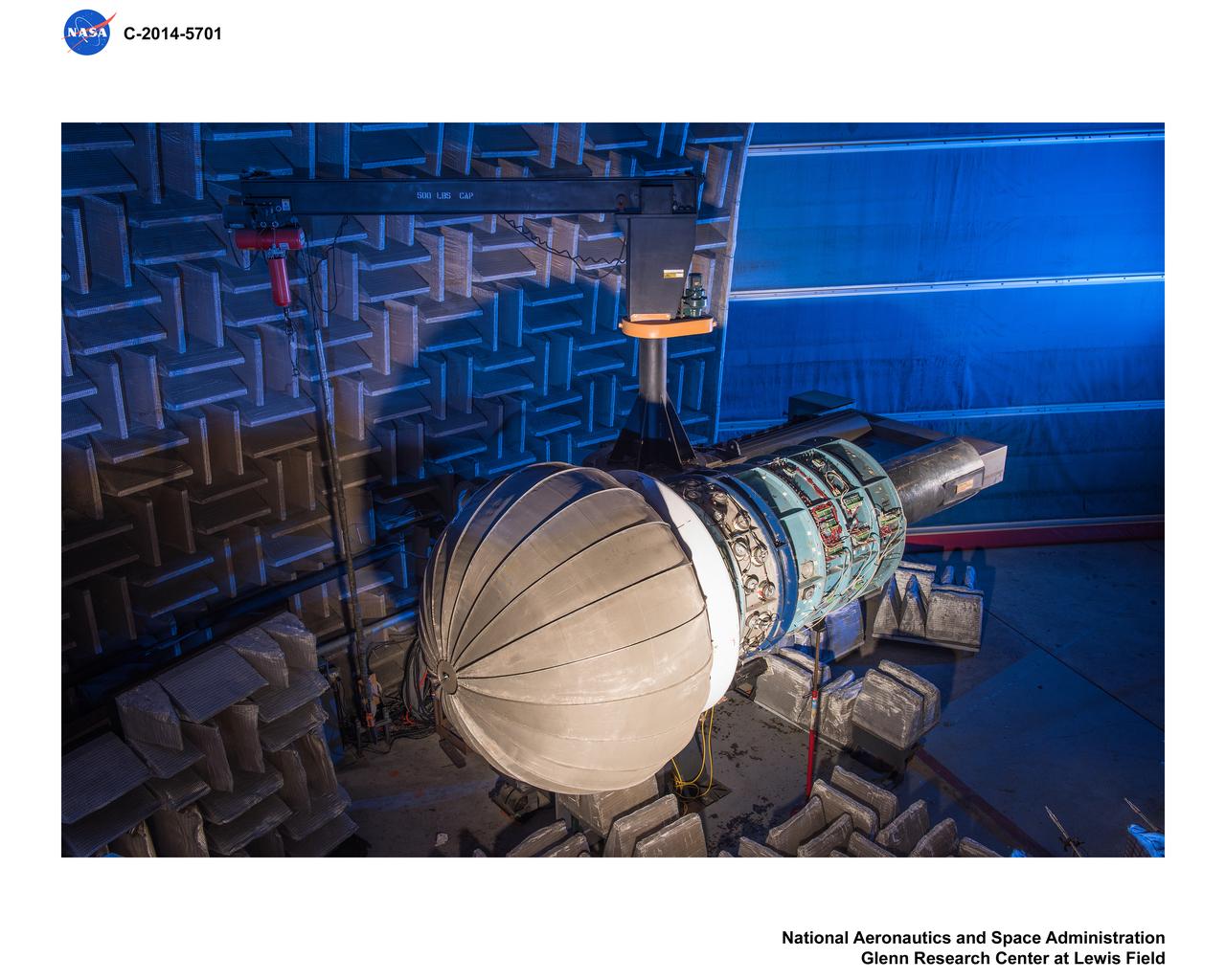
Advanced Noise Control Fan, ANCF, in the Aero-Acoustic Propulsion Laboratory, AAPL
High Speed Research (HSR) Source Noise Test-592, 40x80ft w.t.
MD-900 (N900MH) Helicopter Noise Abatement Test - Crows Landing, Microphones,
Advanced Noise Control Fan, ANCF, in the Aero-Acoustic Propulsion Laboratory, AAPL
Advanced Noise Control Fan, ANCF, in the Aero-Acoustic Propulsion Laboratory, AAPL
High Speed Research (HSR) Source Noise Test-592, 40x80ft w.t.
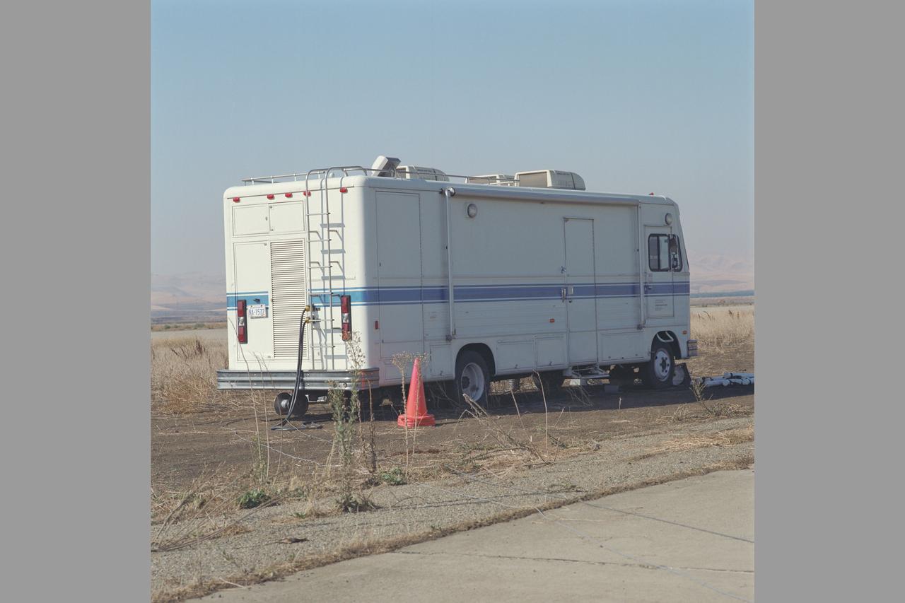
MD-900 (N900MH) Helicopter Noise Abatement Test - Crows Landing, Van
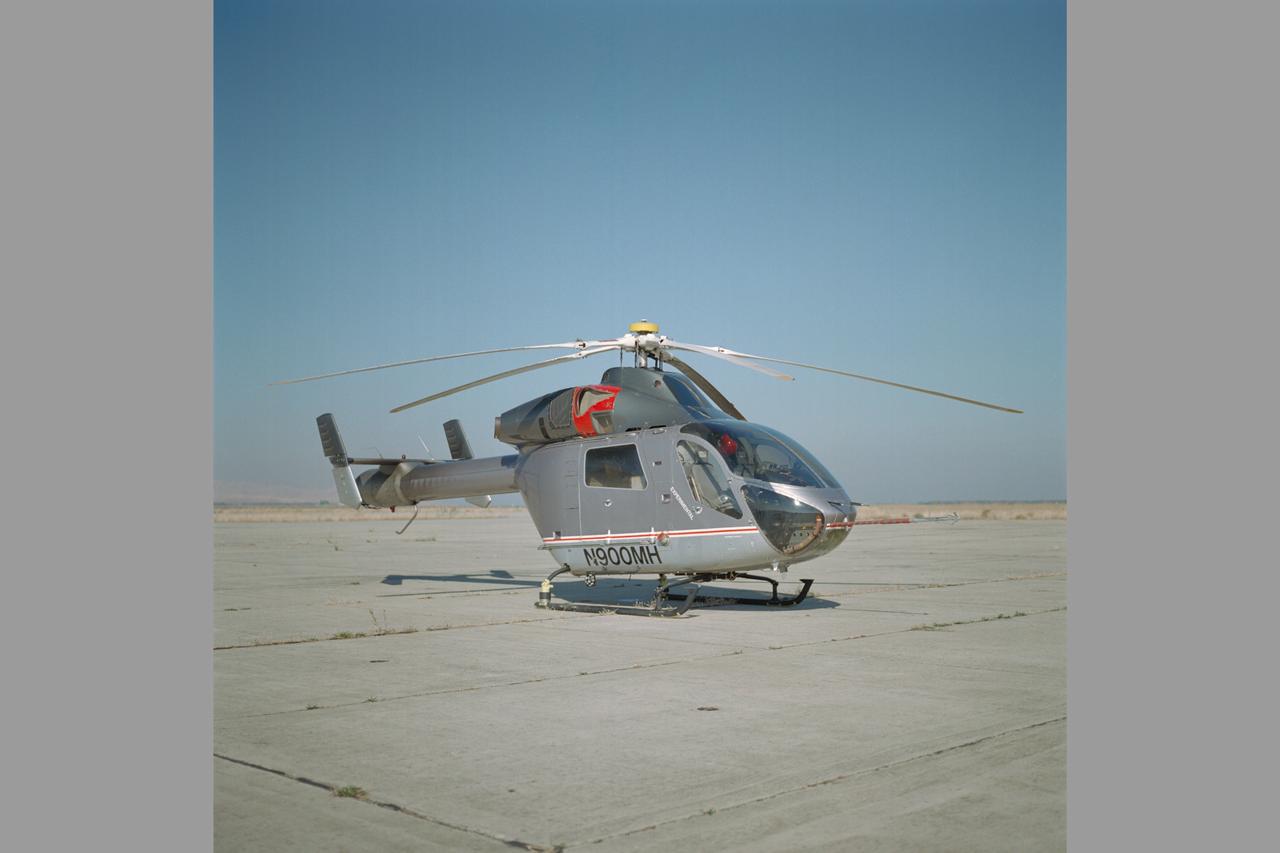
MD-900 (N900MH) Helicopter Noise Abatement Test - Crows Landing
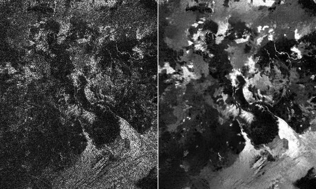
Presented here are side-by-side comparisons of a traditional Cassini Synthetic Aperture Radar (SAR) view, at left, and one made using a new technique for handling electronic noise that results in clearer views of Titan's surface, at right. The technique, called despeckling, produces images that can be easier for researchers to interpret. The terrain seen here is in the flow region named Leilah Fluctus (55 degrees north, 80 degrees west). With the speckle noise suppressed, the overall pattern of bright and dark in the scene becomes more apparent. In particular, cone-shaped features near lower right stand out, which could be alluvial analogues on Titan -- features produced by the action of rivers or floods. North is toward right in this image, which shows an area about 50 miles (80 kilometers) wide. http://photojournal.jpl.nasa.gov/catalog/PIA19054
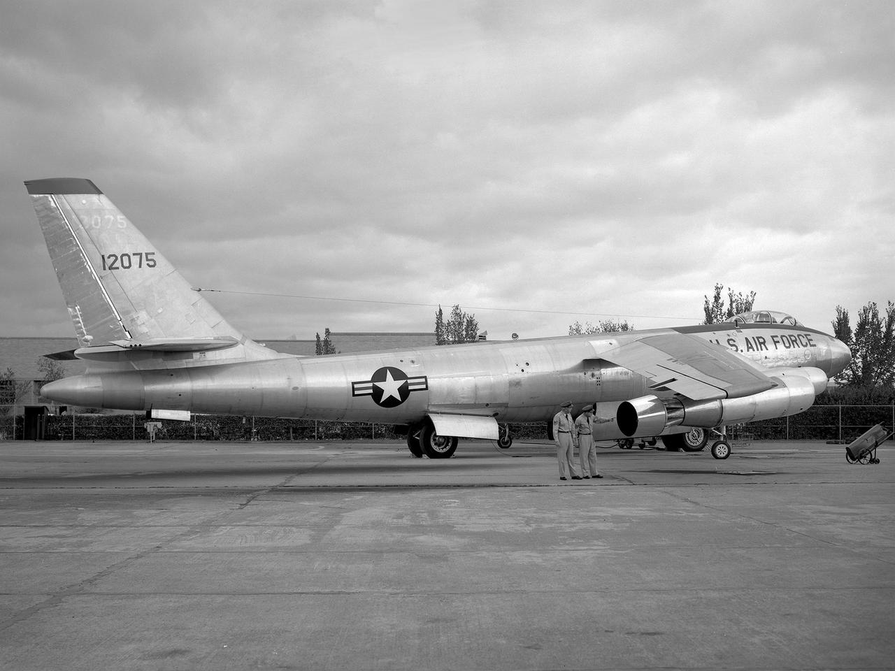
A Boeing B-47 Stratojet bomber with a noise-reducing ejector on its engine at the 1957 Inspection of the National Advisory Committee for Aeronautics (NACA) Lewis Flight Propulsion Laboratory. Representatives from the military, aeronautical industry, universities, and the press were invited to the laboratory to be briefed on the NACA’s latest research efforts and tour the state- of- the- art test facilities. Over 1700 people visited the NACA Lewis in Cleveland, Ohio during October 7 - 10, 1957. By the mid-1950s, the aircraft industry was close to introducing jet airliners to the nation’s airways. The noise produced by the large jet engines, however, would pose a considerable problem for communities near airports. This problem was demonstrated at the 1957 Inspection by an NACA Lewis researcher who played longplay (LP) audio records of military jet engines for an audience. Tests showed that the source of the loudest noise was not the engine itself, but the mixing of the engine’s exhaust with the surrounding air in the atmosphere. The pressures resulting from this turbulence produced sound waves. One of Lewis’ first studies sought to design an exhaust nozzle that reduced the turbulence. A Pratt and Whitney J57 was tested in the Altitude Wind Tunnel with many of these nozzle configurations from January to May 1957. Researchers found that the various nozzle types did reduce the noise levels but also reduced the aircraft’s thrust. Afterwards, they determined that the addition of an NACA-developed ejector reduced the noise levels without diminishing thrust.
XV-15 Rotor Installation in 80X120 ft. Wind Tunnel Test-0048. Noise Reduction
XV-15 Rotor Installation in 80X120 ft. Wind Tunnel Test-0048. Noise Reduction
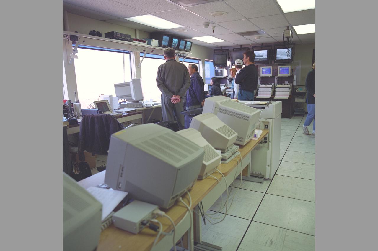
MD-900 (N900MH) Helicopter Noise Abatement Test - Crows Landing, Control Room with test evaluation crew
XV-15 Rotor Installation in 80X120 ft. Wind Tunnel Test-0048. Noise Reduction
OVERHEAD VIEW OF NOZZLE ACOUSTIC TEST RIG POWERED LIFT RIG AND ACTIVE NOISE CONTROL FAN
ACOUSTIC NOISE CONTROL FAN RIG INLET CONTROL DEVICE BOEING ICED TEAM
XV-15 Rotor Installation in 80X120 ft. Wind Tunnel Test-0048. Noise Reduction
XV-15 Rotor Installation in 80X120 ft. Wind Tunnel Test-0048. (microphone set up) Noise Reduction
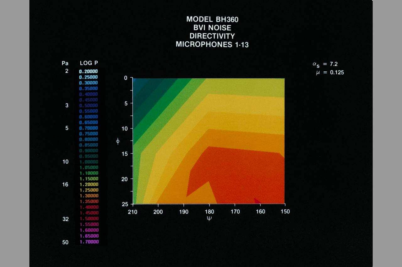
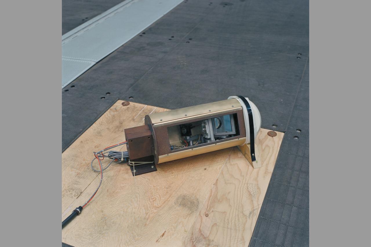
Photo by Dunn Camera System Model BH-360: Conditions for Maximum BVI Noise.
XV-15 Rotor Installation in 80X120 ft. Wind Tunnel Test-0048. Noise Reduction
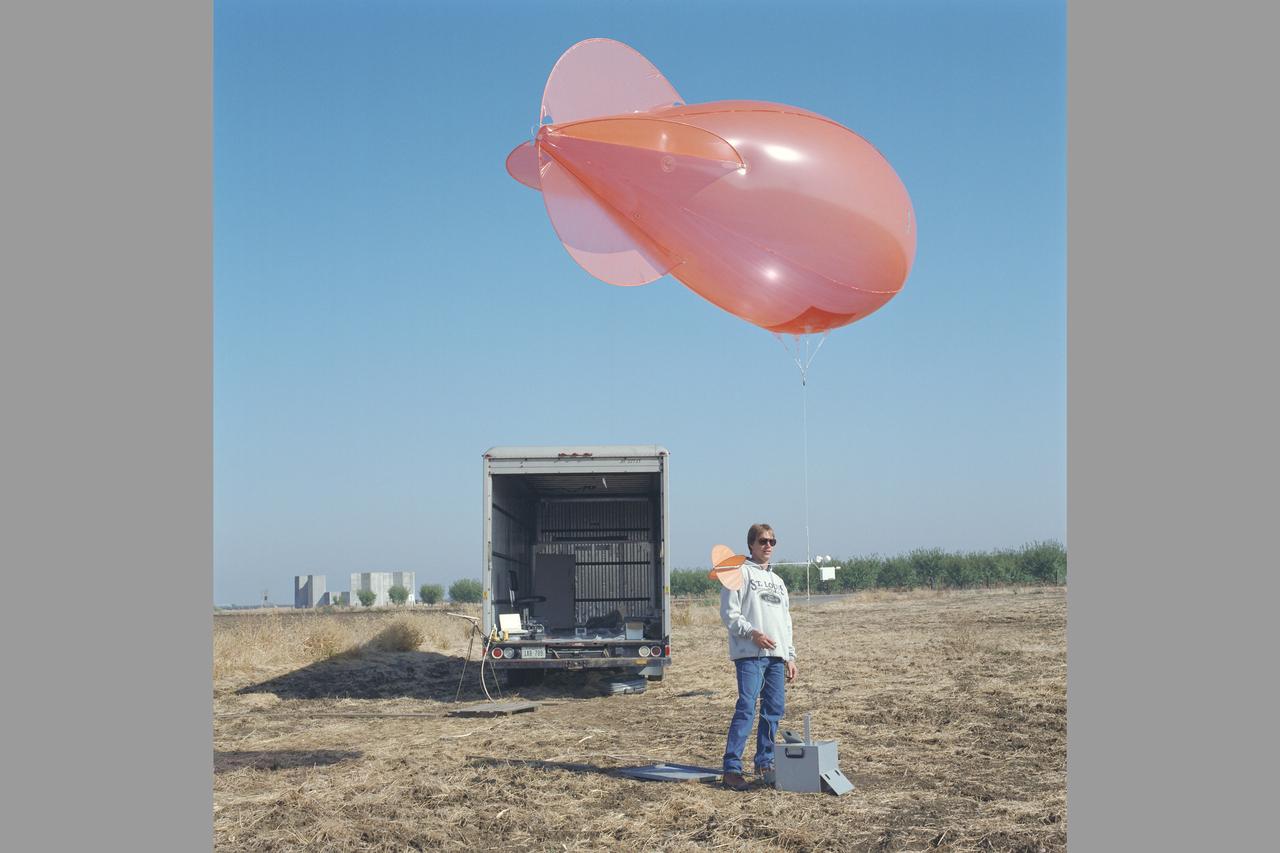
MD-900 (N900MH) Helicopter Noise Abatement Test - Crows Landing, Microphones, Van and balloon blimp (wind indicator)
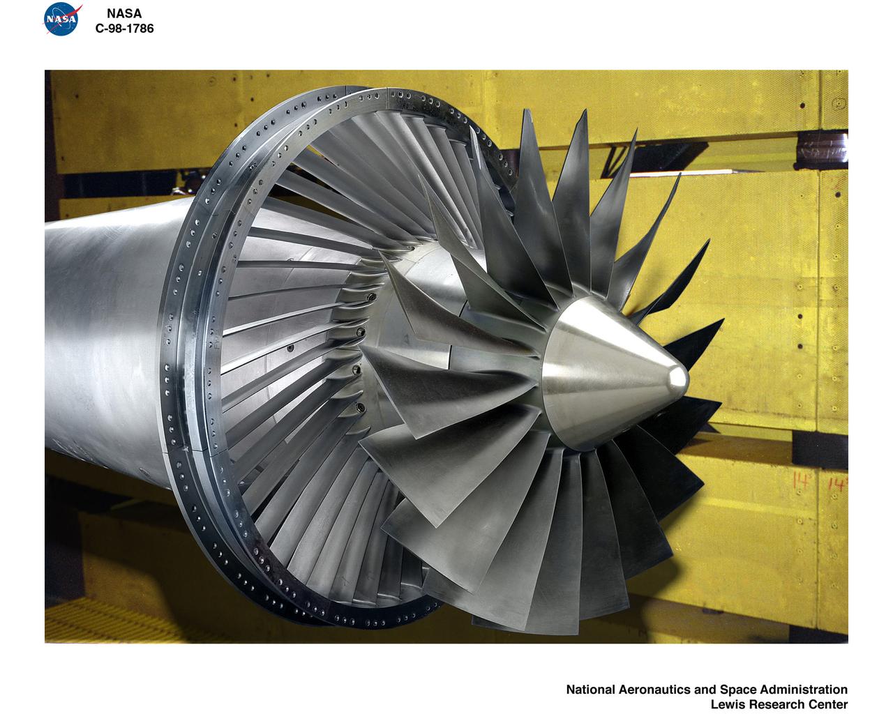
ALLISON LOW SPEED NOISE FAN WITH SWEPT / LEANED STATORS IN 9X15 FOOT LOW SPEED WIND TUNNEL
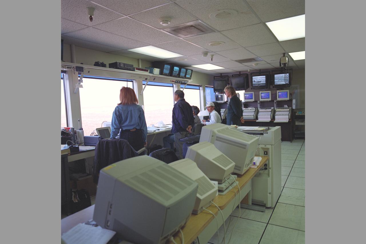
MD-900 (N900MH) Helicopter Noise Abatement Test - Crows Landing, Control Room with test evaluation crew
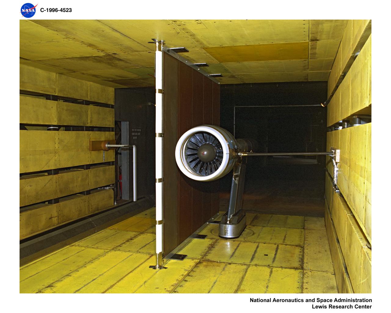
NORTHROP GRUMMAN NOISE REDUCTION TEST 1996 9X15 FOOT WIND TUNNEL ENTRY
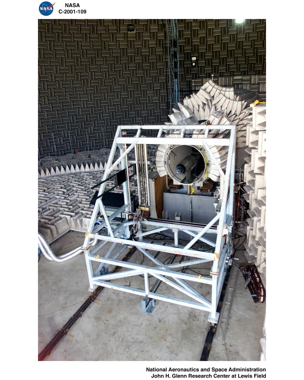
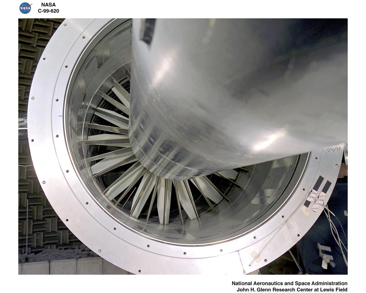
Acoustic Casing Treatment Testing Completed in the W-8 Single Stage Axial Compressor Facility at NASA Glenn. Four different over-the-rotor acoustic casing treatment concepts were tested along with two baseline configurations. Testing included steady-aerodynamic measurements of fan performance, hotfilm turbulence measurements, and inlet acoustic measurements with an in-duct array.
Acoustic Casing Treatment Testing Completed in the W-8 Single Stage Axial Compressor Facility at NASA Glenn. Four different over-the-rotor acoustic casing treatment concepts were tested along with two baseline configurations. Testing included steady-aerodynamic measurements of fan performance, hotfilm turbulence measurements, and inlet acoustic measurements with an in-duct array.
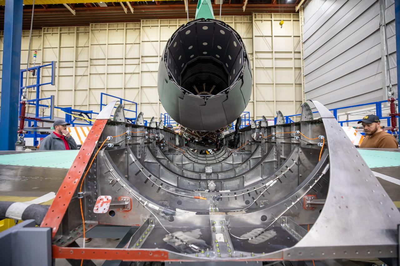
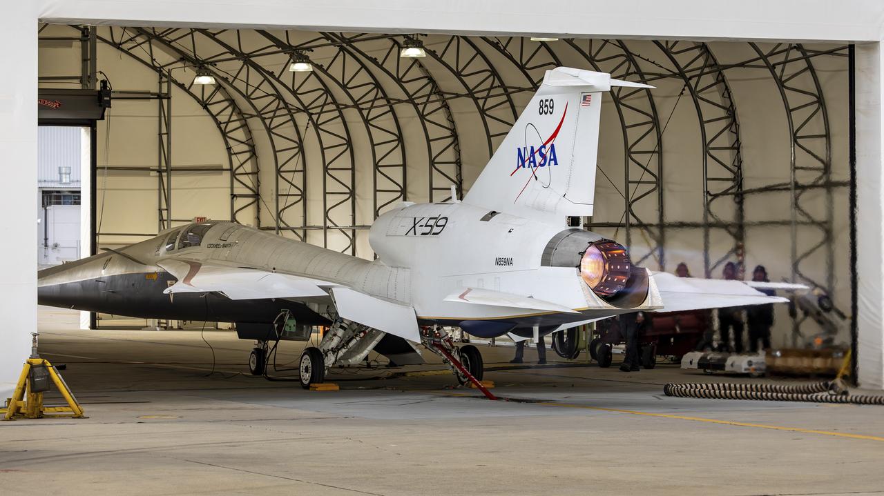
Here is a close-up of the GE F414 engine, from the aft deck or rear, before the tail section of the X-59 is lifted into place and attached to the aircraft. The aft deck helps control the shockwaves at the end of the aircraft and reduce the noise of a sonic boom to more of a sonic thump.
YO-3A during in flight rotorcraft acoustics program Distance Versus Noise Calibration test on BO-105 over Livermore - Central Valley, CA
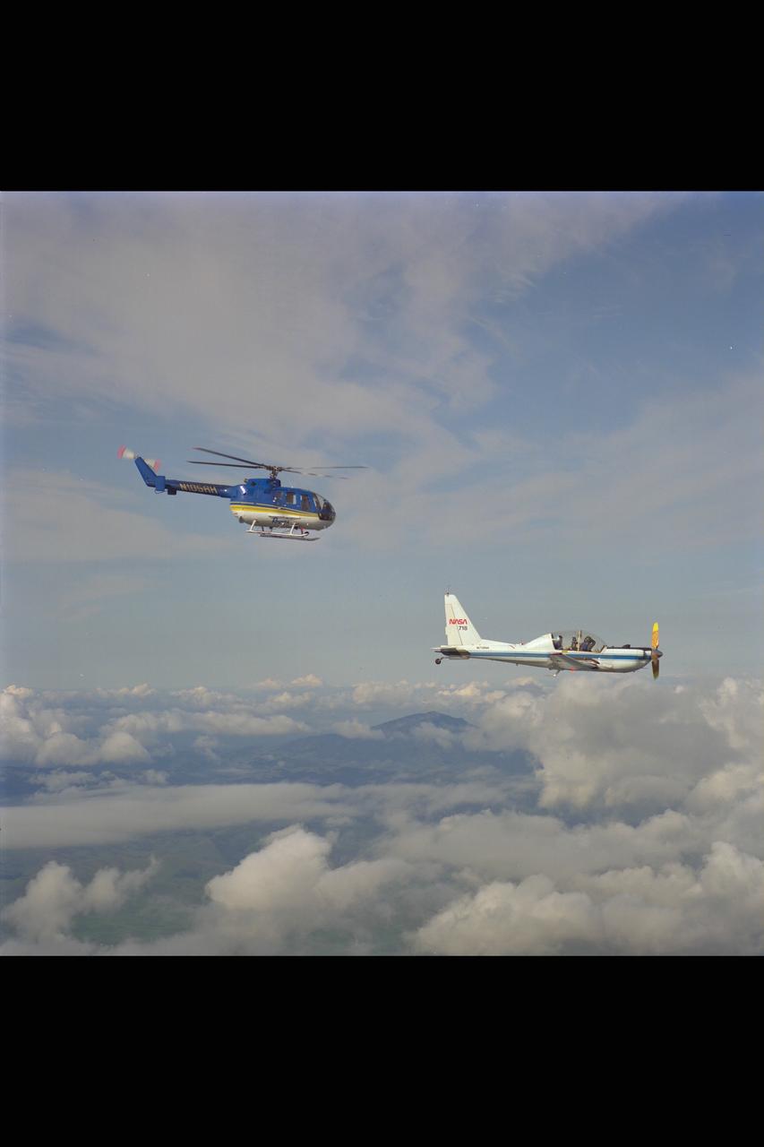
YO-3A (NASA-718) & BO-105 helicopter over Livermore Valley for in flight Rotorcraft Acoustics Program - distance versus noise calibration
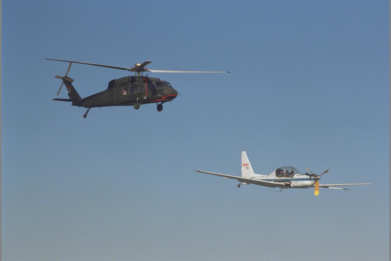
UH-60 Blackhawk (NASA 748) and YO-3A (NASA-718) inflight over Altamont Pass, CA - Blade Vortex Interaction Noise experiment
National Full Scale Aerodynamic Complex (NFAC) located at the NASA Ames Research Center 80x20ft. wind tunnel microphone array background noise test
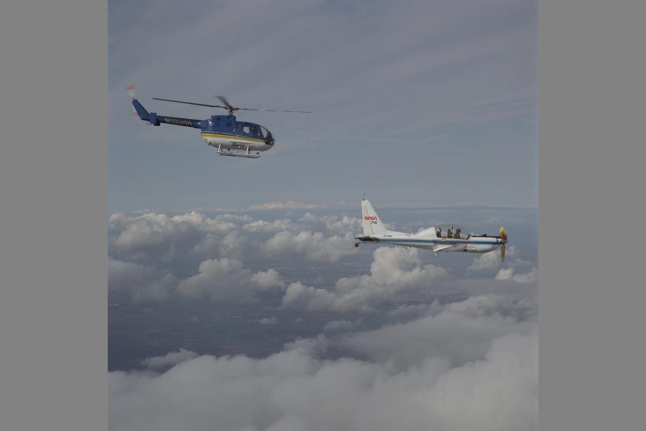
YO-3A (NASA 718) and BO-105 helicopter over Livermore Valley, CA: In-flight rotorcraft acoustics program (distance versus noise calibration)
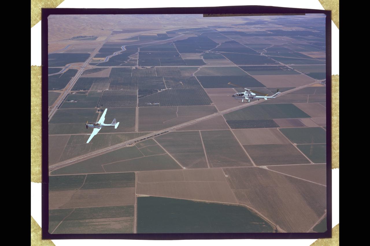
Y0-3A (NASA-718) Quiet Plane and AH-1G (NASA-736) helicopter during noise abatement flight test at Crow Landing facility
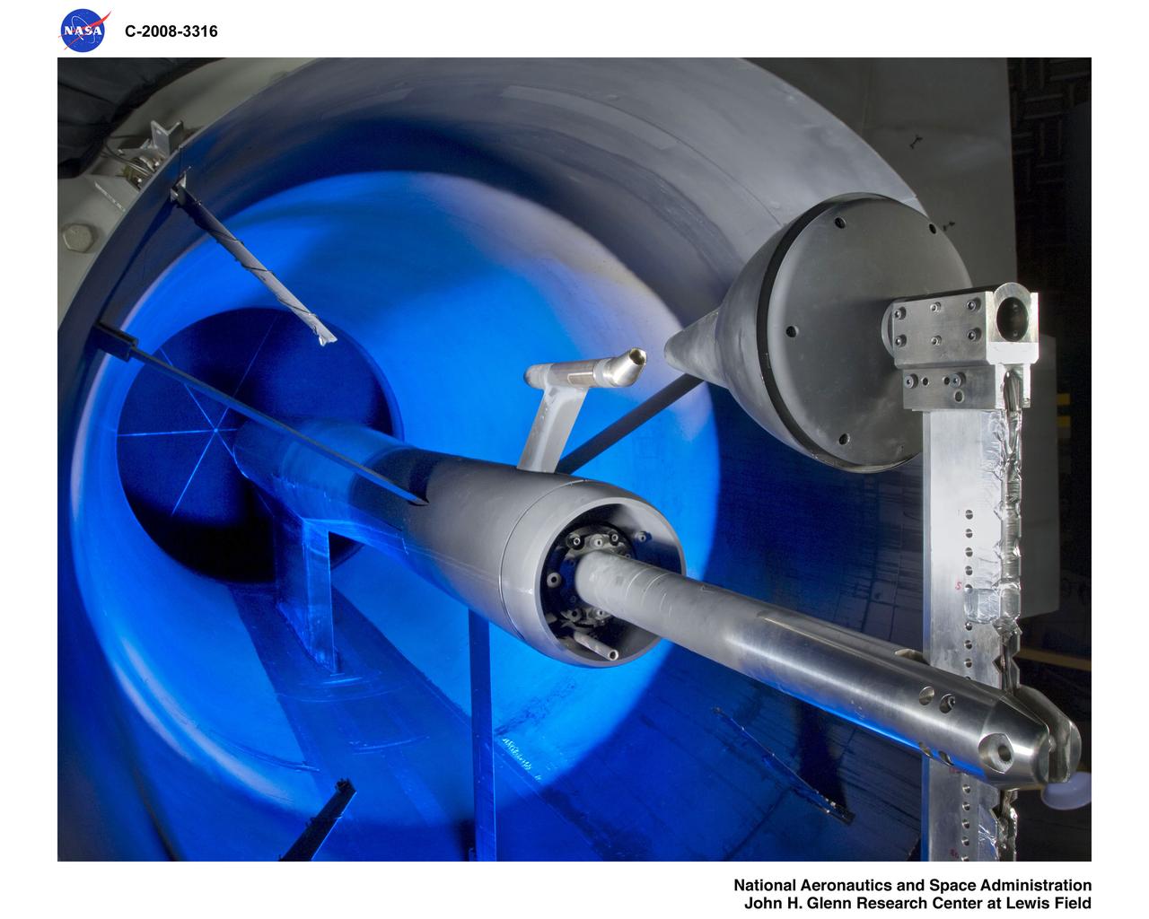
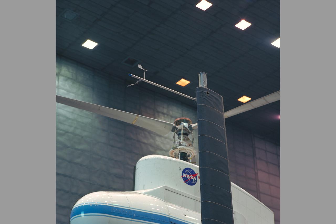
Noise Accoustical Test Rig (NATR) Crew Exploration Vehicle (CEV) 85-AA-Constellation, Orion Capsule and nozzle on front of NATR
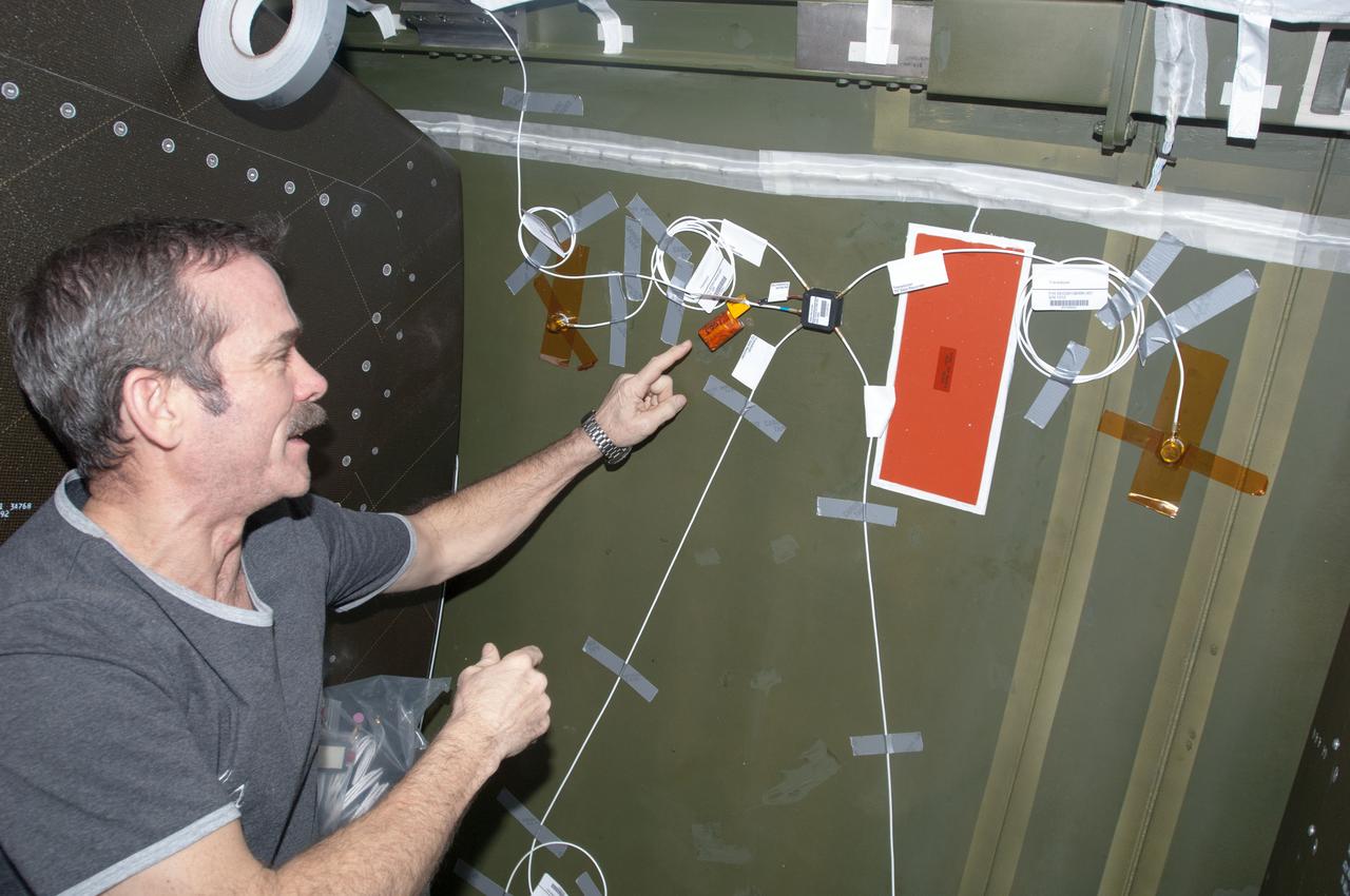
ISS034-E-038211 (1 Feb. 2013) --- Canadian Space Agency astronaut Chris Hadfield, Expedition 34 flight engineer, installs Ultra-Sonic Background Noise Tests (UBNT) sensors behind a rack in the Destiny laboratory, using the International Space Station (ISS) as Testbed for Analog Research (ISTAR) procedures. These sensors detect high frequency noise levels generated by ISS hardware and equipment operating within Destiny.
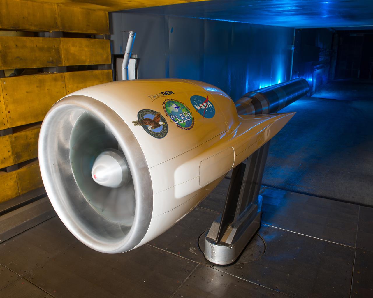
Ultra High Bypass Integrated System Test Testing of an Ultra High Bypass Ratio Turbofan model in the 9-by 15-Foot Low Speed Wind Tunnel. Pratt & Whitney designed the experimental engine to meet new efficiency and noise reduction targets for commercial aircraft set by NASA and the Federal Aviation Administration. The 9-by 15 tests analyzed two noise reduction technologies.
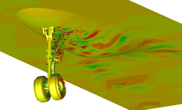
Snapshot from a simulation run on the Pleiades supercomputer. It depicts a fluctuating pressure field on aircraft nose landing gear and fuselage surfaces. The simulation helped scientists better understand the effects of landing gear and acoustic noise. The goal of the study was to improve the current understanding of aircraft nose landing gear noise, which will lead to quieter, more efficient airframe components for future aircraft designs. The visualization was produced with help from the NAS Data Analysis & Visualization group. Investigator: Mehdi Khorrami, NASA Langley Research Center.

NASA’s 2017 astronaut candidates (L to R) Jessica Watkins, Zena Cardman, Kayla Barron toured aircraft hangar at Armstrong Flight Research Center, in Southern California where they were briefed on the use of Armstrong's F-15 and F-18 aircraft for studying sonic booms. The aircraft will be used during the development of the low-boom X-59 aircraft that is planned to fly supersonically over land, which is not allowed at this time because of the loud noise created when flying beyond the speed of sound.

A Republic F-84 Thunderjet dramatically modified at the NASA Lewis Research Center to investigate the use of slotted nozzles to reduce exhaust noise. The F-84 was a single-seat fighter-bomber powered by an Allison J35 turbojet. It was the Air Force’s first post-World War II tactical aircraft and was used extensively in the Korean War. The laboratory had acquired the aircraft in 1954 and modified it in order to demonstrate the reverse thruster. The tail end of the aircraft was then removed for a series of large nozzle investigations. Lewis researchers launched an extensive program in the mid-1950s to develop methods of reducing engine noise as the airline industry was preparing to introduce the first turbojet-powered passenger aircraft. The early NACA investigations determined that the primary source of noise was the mixing of the engine’s hot exhaust with the cool surrounding air. Lewis researchers studied many different nozzles designed to facilitate this mixing. Nozzles with elongated exit sections, as seen in this photograph, produced lower noise levels. These long slot nozzles were also considered for Short Take-off and Landing aircraft because their long flat surfaces provided lift. In 1958 Lewis tested several full-scale slot nozzles on the F-84. The researchers, led by Willard Cole, sought to determine the noise-generation characteristics for nozzles having large a width-to-height ratio. The nozzle in this photograph has a 100 to 1 width-to-height ratio. Cole determined that the experimental nozzles produced the same levels of sound as the standard nozzle, but the changes in the directional noise were substantial.
Brent Miller, of the V/STOL and Noise Division at the National Aeronautics and Space Administration (NASA) Lewis Research Center, poses with a sonic inlet for the NASA Quiet Engine Program. NASA Lewis had first investigated methods for reducing aircraft engine noise in the mid-1950s. Those efforts were resurrected and expanded in the late 1960s. The researchers found that the use of a sonic, or high-throat-Mach-number, inlet was effective at reducing the noise from the engine inlet. The device accelerated the inlet air to near-sonic speeds which kept the forward moving sound waves away from the inlet. The device also deflected the sound waves into the wall to further reduce the noise. NASA Lewis researchers tested models of the sonic inlet in their 9- by 15-Foot Low Speed Wind Tunnel. They found that the general level of aerodynamic performance was good. The tests during simulated takeoff and landing conditions demonstrated the sonic inlet’s ability to provide good aerodynamic and acoustic performance The researchers then successfully tested two full-scale sonic inlet designs, one from Pratt and Whitney and one from General Electric, with fans. A full-scale engine was installed on a thrust stand to determine the sonic inlet’s effect on the engine’s performance. The amount of noise reduction increased as the inlet flow velocity increased, but the full-scale tests did not produce as great a decrease in noise as the earlier small-scale tests.
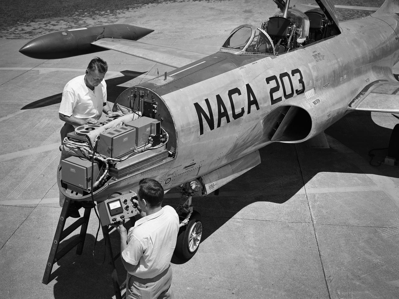
A Lockheed F-94B Starfire being equipped with an audio recording machine and sensors at the National Advisory Committee for Aeronautics (NACA) Lewis Flight Propulsion Laboratory. The NACA was investigating the acoustic effects caused by the engine’s nozzle and the air flowing along the fuselage. Airline manufacturers would soon be introducing jet engines on their passenger aircraft, and there was concern regarding the noise levels for both the passengers and public on the ground. NACA Lewis conducted a variety of noise reduction studies in its wind tunnels, laboratories, and on a F2H-2B Banshee aircraft. The F2H-2B Banshee’s initial test flights in 1955 and 1956 measured the noise emanating directly from airflow over the aircraft’s surfaces, particularly the wings. This problem was particularly pronounced at high subsonic speeds. The researchers found the majority of the noise occurred in the low and middle octaves. These investigations were enhanced with a series of flights using the F-94B Starfire. The missions measured wall-pressure, turbulence fluctuations, and mean velocity profiles. Mach 0.3 to 0.8 flights were flown at altitudes of 10,000, 20,000, and 30,000 feet with microphones mounted near the forward fuselage and on a wing. The results substantiated the wind tunnel findings. This photograph shows the tape recorder being installed in the F-94B’s nose.
ISS034-E-030218 (16 Jan. 2013) --- NASA astronaut Kevin Ford, Expedition 34 commander, installs a Ultra-Sonic Background Noise Tests (UBNT) sensor kit behind a rack in the Destiny of the International Space Station.

Oblique Wing model mounted in 11ft W. T. with R. T. Jones, Designer/Engineer. The asymmetrical design allows the plane to fly much faster, yet consume the same fuel and generate less noise.
view of YO-3A from cockpit of BO-105 helicopter during in flight rotorcraft acoustics program Distance Versus Noise Calibration over Livermore - Central Valley, CA
ISS034-E-030216 (16 Jan. 2013) --- NASA astronaut Kevin Ford, Expedition 34 commander, installs a Ultra-Sonic Background Noise Tests (UBNT) sensor kit behind a rack in the Destiny of the International Space Station.
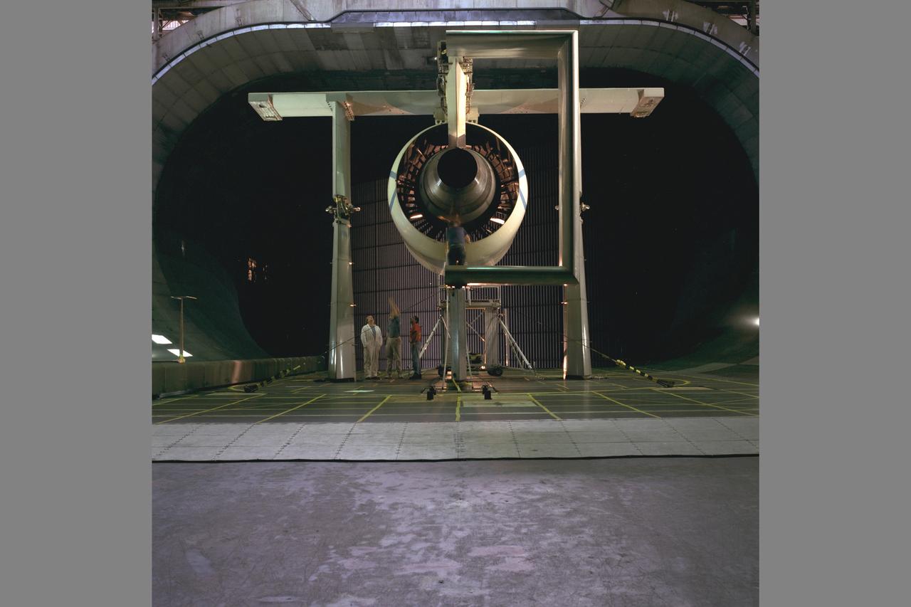
AST (Advanced Supersonic Technology) Propulsion Noise Research test on the F-15 model with nacelle in the 40x80ft Subsonic Wind Tunnel at Ames Research Center, Mt View, CA
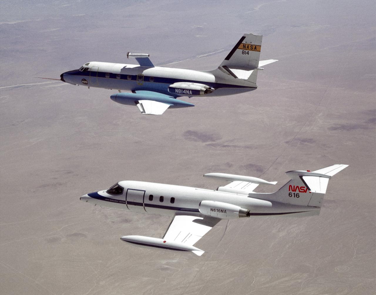
The NASA C-140 JetStar research aircraft (top) is followed by a NASA Learjet equipped with acoustic sensors during one of several tests of advanced propellors mounted on the vertical pylon atop the JetStar's fuselage. Several advanced prop designs were tested on the JetStar in 1982 by NASA's Dryden Flight Research Facility (DFRF), Edwards, California, to study the effects of noise created by propellors on aircraft structures and cabin interiors. To assess possible noise problems with the subscale turbofan, DFRF technicians mounted microphones on both the JetStar and the Learjet chase plane. DFRF then made measurements at close range and at longer distances. The data enabled structural changes and flightpath modifications.
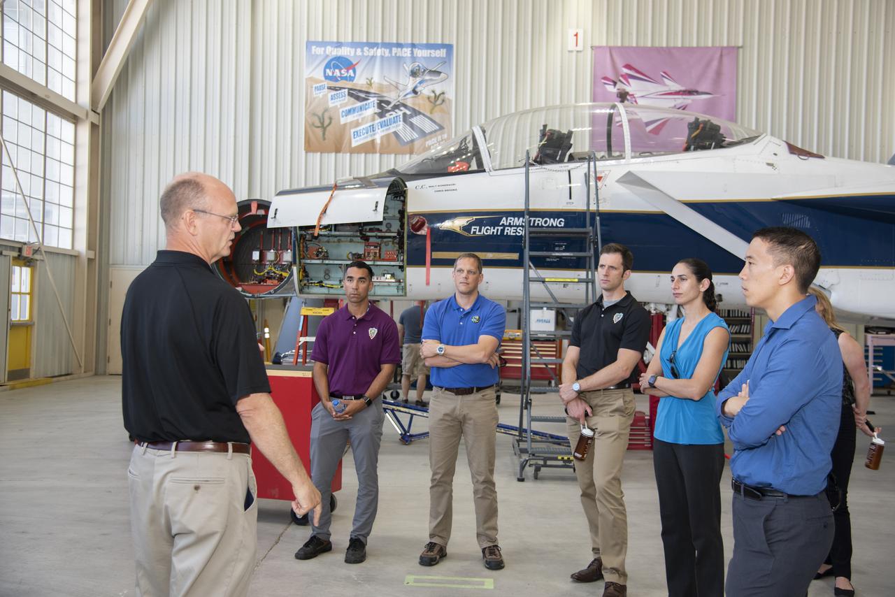
NASA’s 2017 astronaut candidates (L to R) Raja Chari, Bob Hines, Joshua Kutryk, Jasmin Moghbeli, Jonny Kim, and Jessica Watkins toured aircraft hangar at Armstrong Flight Research Center, in Southern California. On the left, NASA’s, X-59 pilot, briefs them on use of F-15 for studying sonic booms during the development of the low-boom X-59 aircraft that is planned to fly supersonically over land. Low-level supersonic flight is not allowed at this time because of the loud noise levels generated when flying beyond the speed of sound.

Presented here are side-by-side comparisons of a traditional Cassini Synthetic Aperture Radar (SAR) view and one made using a new technique for handling electronic noise that results in clearer views of Titan's surface. The technique, called despeckling, produces images that can be easier for researchers to interpret. The view is a mosaic of SAR swaths over Ligeia Mare, one of the large hydrocarbons seas on Titan. In particular, despeckling improves the visibility of channels flowing down to the sea. http://photojournal.jpl.nasa.gov/catalog/PIA19052
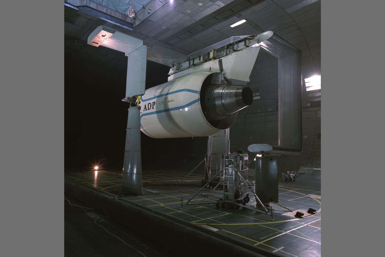
Pratt & Whitney Advanced Ducted Propulsor (ADP) Engine Test-590 in the NASA Ames 40x80ft Subsonic Wind Tunnel. The Pratt & Whitney Advanced Ducted Prop (ADP) demonstrator undergoing acoustic and fan performance testing. ADP technology could lead to decreased fuel consumption and noise.
Pratt & Whitney Advanced Ducted Propulsor (ADP) Engine Test-590 in NASA Ames 40x80ft Subsonic Wind Tunnel. The Pratt & Whitney advanced ducted prop (ADP) demonstrator undergoing acoustic and fan performance testing. ADP technology could lead to decreased fuel consumption and noise.
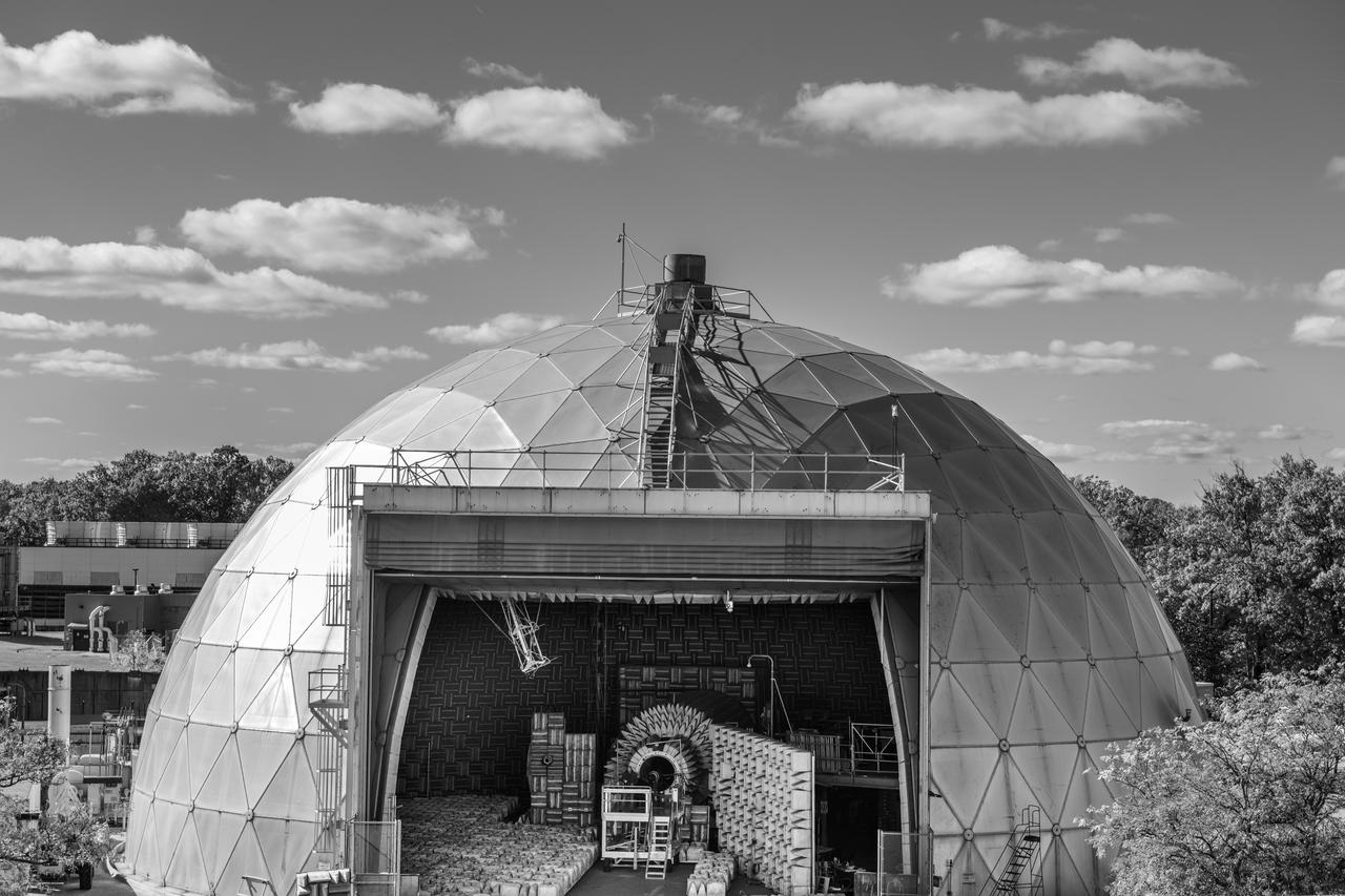
The Aero-Acoustic Propulsion Laboratory (AAPL) photographed on October 24, 2024 as seen from above. This facility provides world class testing for aircraft propulsion acoustic noise reduction and is 65 ft high by 130 ft in diameter. Photo Credit: (NASA/Sara Lowthian-Hanna)
ISS034-E-037330 (31 Jan. 2013) --- Canadian Space Agency astronaut Chris Hadfield, Expedition 34 flight engineer, installs a Ultra-Sonic Background Noise Tests (UBNT) sensor kit behind a rack in the Destiny of the International Space Station.
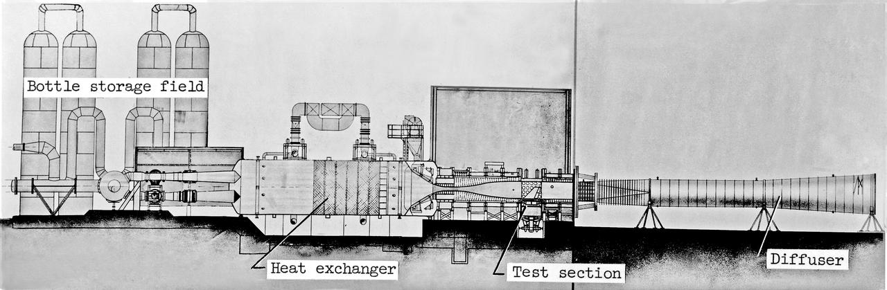
Scale Model of 9x6 Thermal Structures Tunnel: Image L-7256.01 is a Drawing Figure 12 in NASA Document L-1265. The Major components of the 9-by6-Foot Thermal Structures Tunnel. The 97 foot-long diffuser was added in 1960 to reduce noise.
Claudia Sales, NASA’s acting X-59 deputy chief engineer and airworthiness certification lead for the quiet supersonic research aircraft, supports ground testing for Acoustic Research Measurements (ARM) flights. The test campaign to evaluate technologies that reduce aircraft noise was conducted at NASA’s Armstrong Flight Research Center in Edwards, California, in 2018.
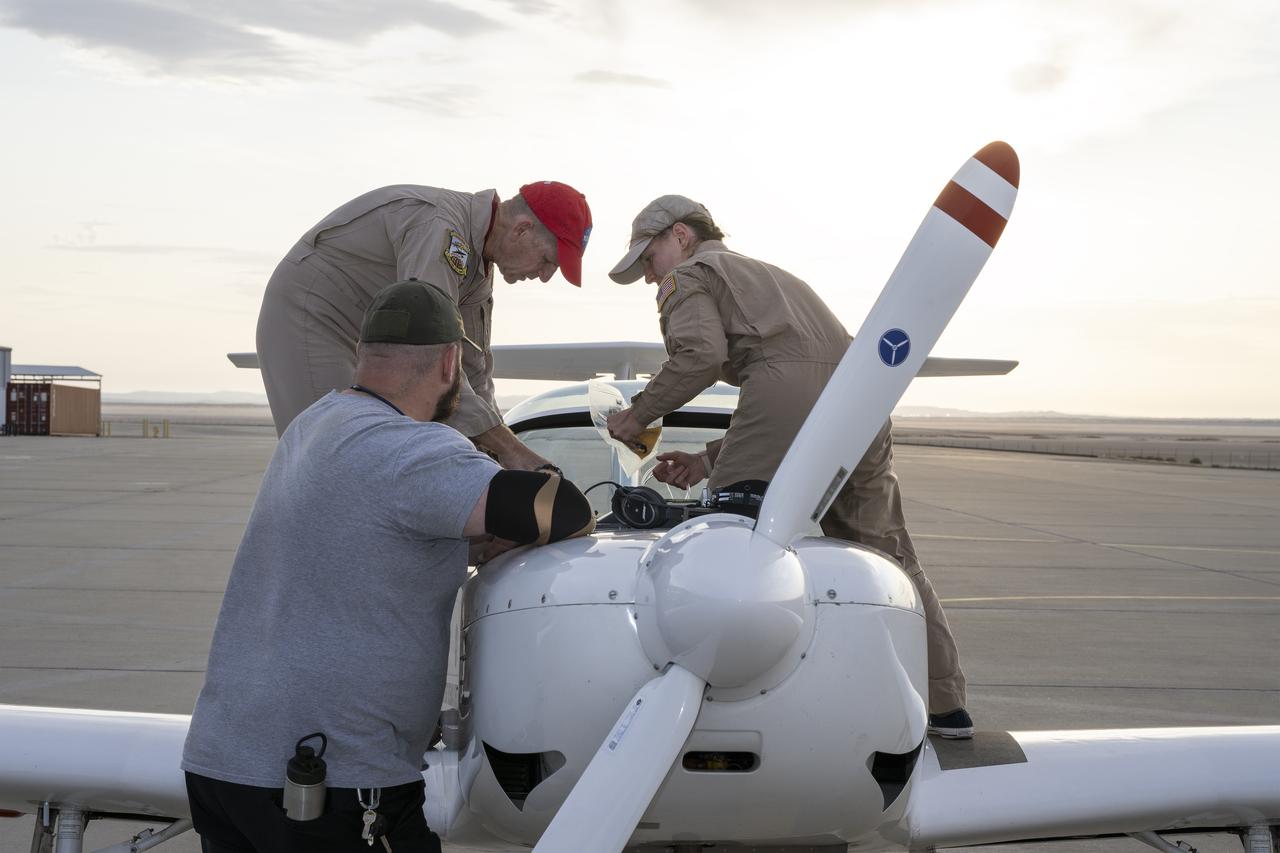
A NASA TG-14 glider aircraft is prepared for flight at NASA’s Armstrong Flight Research Center in Edwards, California, in support of the agency’s Quesst mission. The aircraft is equipped with onboard microphones to capture sonic boom noise generated during rehearsal flights, helping researchers measure the acoustic signature of supersonic aircraft closer to the ground.
BO-105 helicopter pilot & cockpit during in flight rotorcraft acoustics program Distance Versus Noise Calibration over Livermore - Central Valley, CA. The YO-3A flying the acoustics test can just be seen through cockpit window.
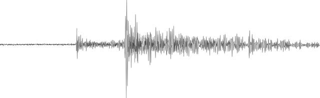
NASA's InSight lander detected a marsquake, represented here as a seismogram, on July 25, 2019, the 235th Martian day, or sol, of its mission. Seismologists study the wiggles in seismograms in order to confirm whether they're really seeing a quake or noise caused by wind. https://photojournal.jpl.nasa.gov/catalog/PIA24761
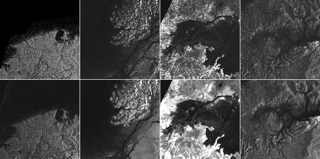
This montage of Cassini Synthetic Aperture Radar (SAR) images of the surface of Titan shows four examples of how a newly developed technique for handling noise results in clearer, easier to interpret views. The top row of images was produced in the manner used since the mission arrived in the Saturn system a decade ago; the row at bottom was produced using the new technique. The three leftmost image pairs show bays and spits of land in Ligea Mare, one of Titan's large hydrocarbon seas. The rightmost pair shows a valley network along Jingpo Lacus, one of Titan's larger northern lakes. North is toward the left in these images. Each thumbnail represents an area 70 miles (112 kilometers) wide. http://photojournal.jpl.nasa.gov/catalog/PIA19053
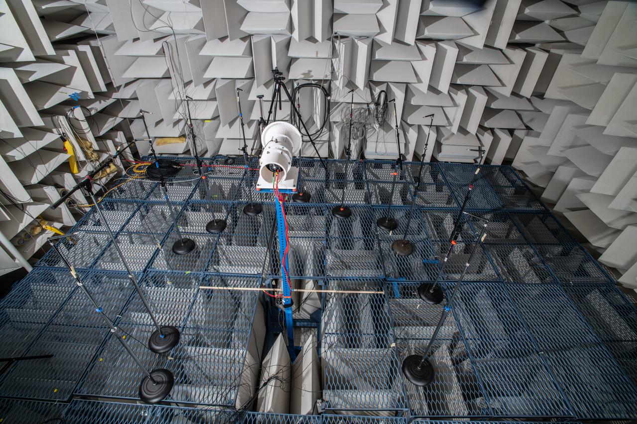
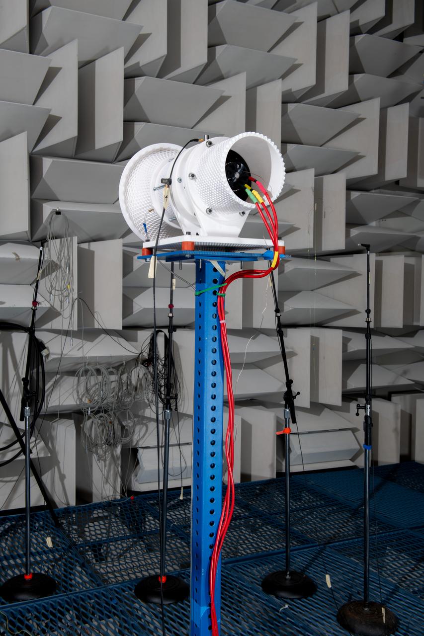
The Quiet Electric Engine V1 (QUEEN V1) experiment that was performed in the NASA GRC Acoustical Testing Laboratory (ATL). Equipment is installed in the anechoic chamber and in the adjacent control room. In response to the pervasive health and environmental problems associated with aviation noise and air pollution, NASA’s Quiet Electric Engine (QUEEN) team is working to increase the peace and quiet in the world by researching ways to make engines for large single-aisle aircraft safer, cleaner, and quieter.
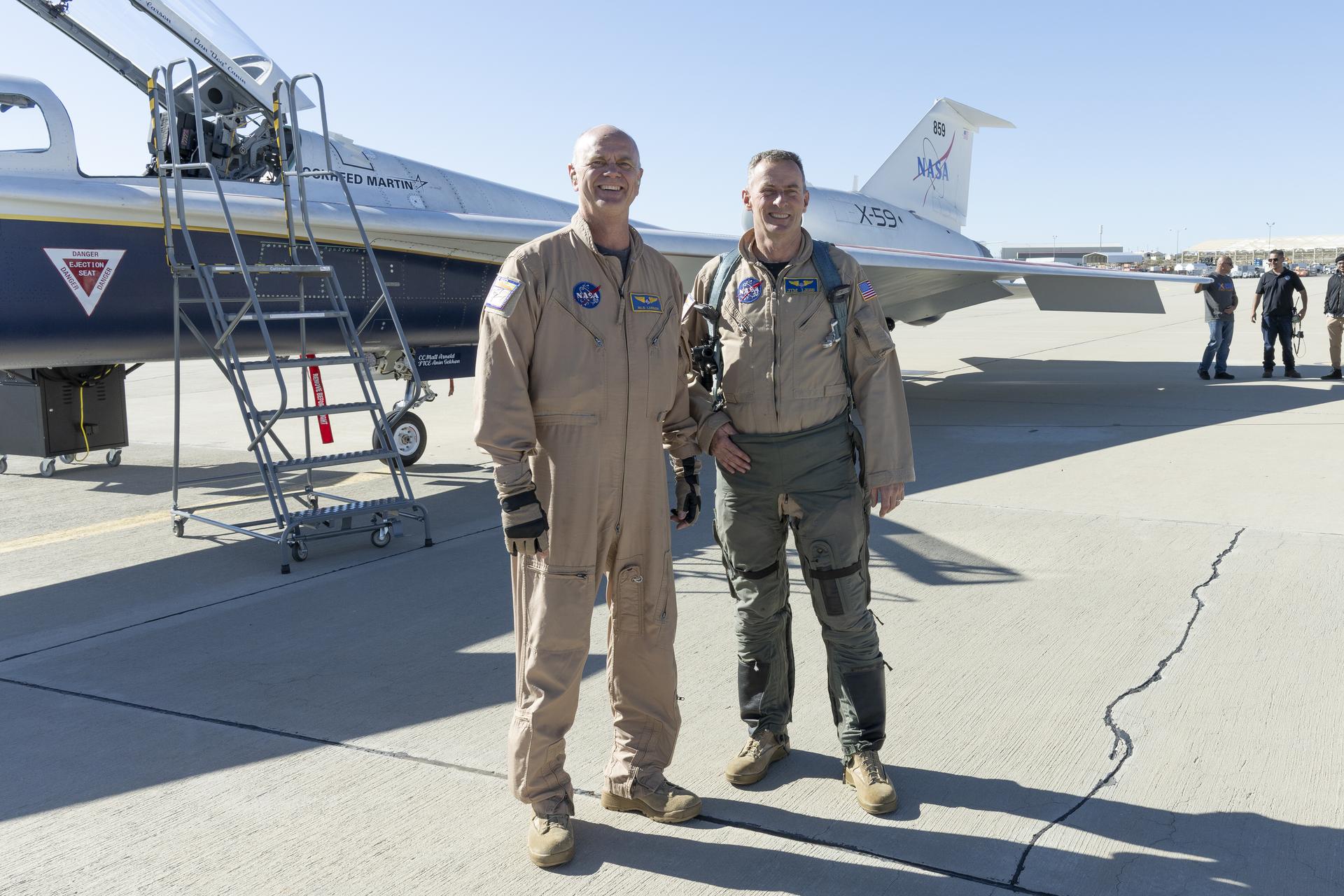
NASA chase pilot Jim “Clue” Less congratulates Nils Larson after completing the X-59’s first flight on Tuesday, Oct. 28, 2025. The milestone marks a major step toward demonstrating quiet supersonic technology that could enable future air travel over land without the disruptive noise of traditional sonic booms.
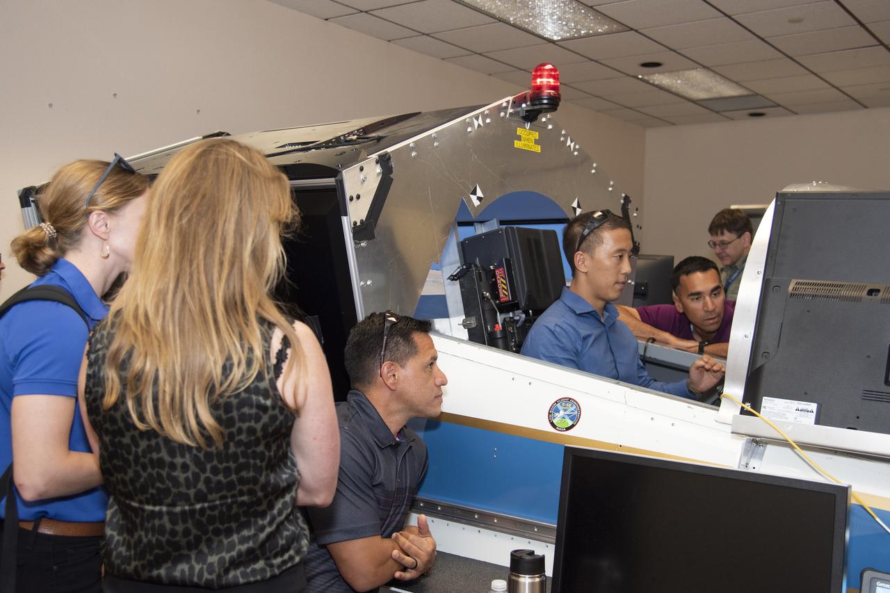
NASA's 2017 astronaut candidates (L to R) Zena Cardman, Loral O'Hara, Frank Rubio, Jonny Kim, Raja Chari practice flying in an X-59 QueSST simulator at Armstrong Flight Research Center, in Southern California. The low boom flight demonstrator, X-59, being built at Lockheed Martin and was designed to fly at supersonic speeds over land without the loud noise of breaking the sound barrier and disturbing communities.
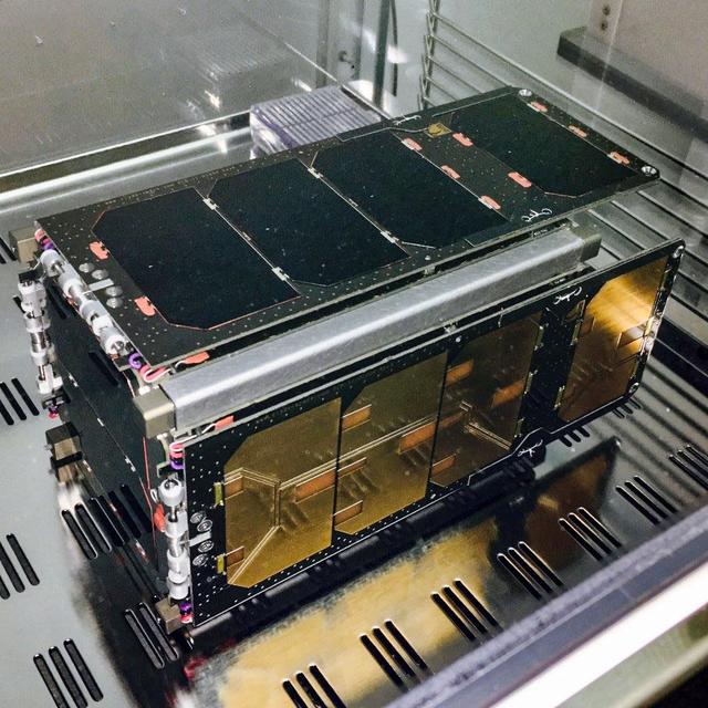
Jsc2020e004942(2/7/2020) — A preflight view of the CryoCube BUS. CryoCube demonstrates on-orbit thermal management technology. Such technology has a variety of potential applications, including storing rocket propellants in space, cooling instruments to improve their signal-to-noise ratios, and supporting future cryogenic experiments in microgravity. The small satellite uses a deployable shield to block radiation from the Sun and Earth and an attitude control system to point its experiment into deep space. Image courtesy of: Sierra Lobo Inc.
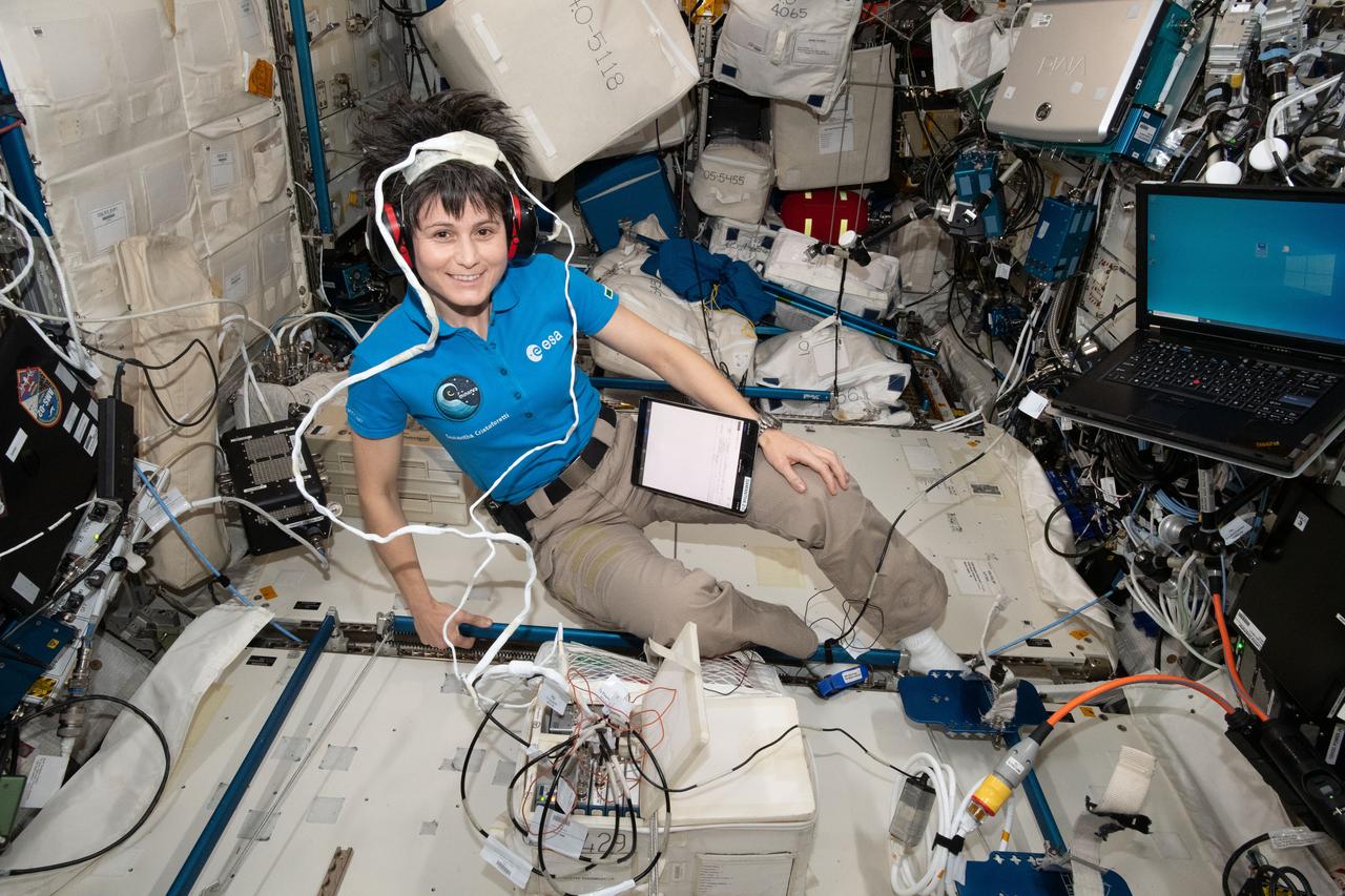
iss067e183752_alt (July 8, 2022) --- Expedition 67 Flight Engineer and ESA (European Space Agency) astronaut Samantha Cristoforetti participates in the Acoustic Diagnostics study. The investigation explores whether equipment noise levels and the microgravity environment may create possible adverse effects on astronaut hearing. The acoustic data will help researchers understand the International Space Station’s sound environment and may inform countermeasures to protect crew hearing.
NASA’s X-59 quiet supersonic research aircraft completed its first maximum afterburner test at Lockheed Martin’s Skunk Works facility in Palmdale, California. This full-power test, during which the engine generates additional thrust, validates the additional power needed for meeting the testing conditions of the aircraft. The X-59 is the centerpiece of NASA’s Quesst mission, which aims to overcome a major barrier to supersonic flight over land by reducing the noise of sonic booms.

The Quiet Electric Engine V1 (QUEEN V1) experiment that was performed in the NASA GRC Acoustical Testing Laboratory (ATL). Equipment is installed in the anechoic chamber and in the adjacent control room. In response to the pervasive health and environmental problems associated with aviation noise and air pollution, NASA’s Quiet Electric Engine (QUEEN) team is working to increase the peace and quiet in the world by researching ways to make engines for large single-aisle aircraft safer, cleaner, and quieter.
The Quiet Electric Engine V1 (QUEEN V1) experiment that was performed in the NASA GRC Acoustical Testing Laboratory (ATL). Equipment is installed in the anechoic chamber and in the adjacent control room. In response to the pervasive health and environmental problems associated with aviation noise and air pollution, NASA’s Quiet Electric Engine (QUEEN) team is working to increase the peace and quiet in the world by researching ways to make engines for large single-aisle aircraft safer, cleaner, and quieter.
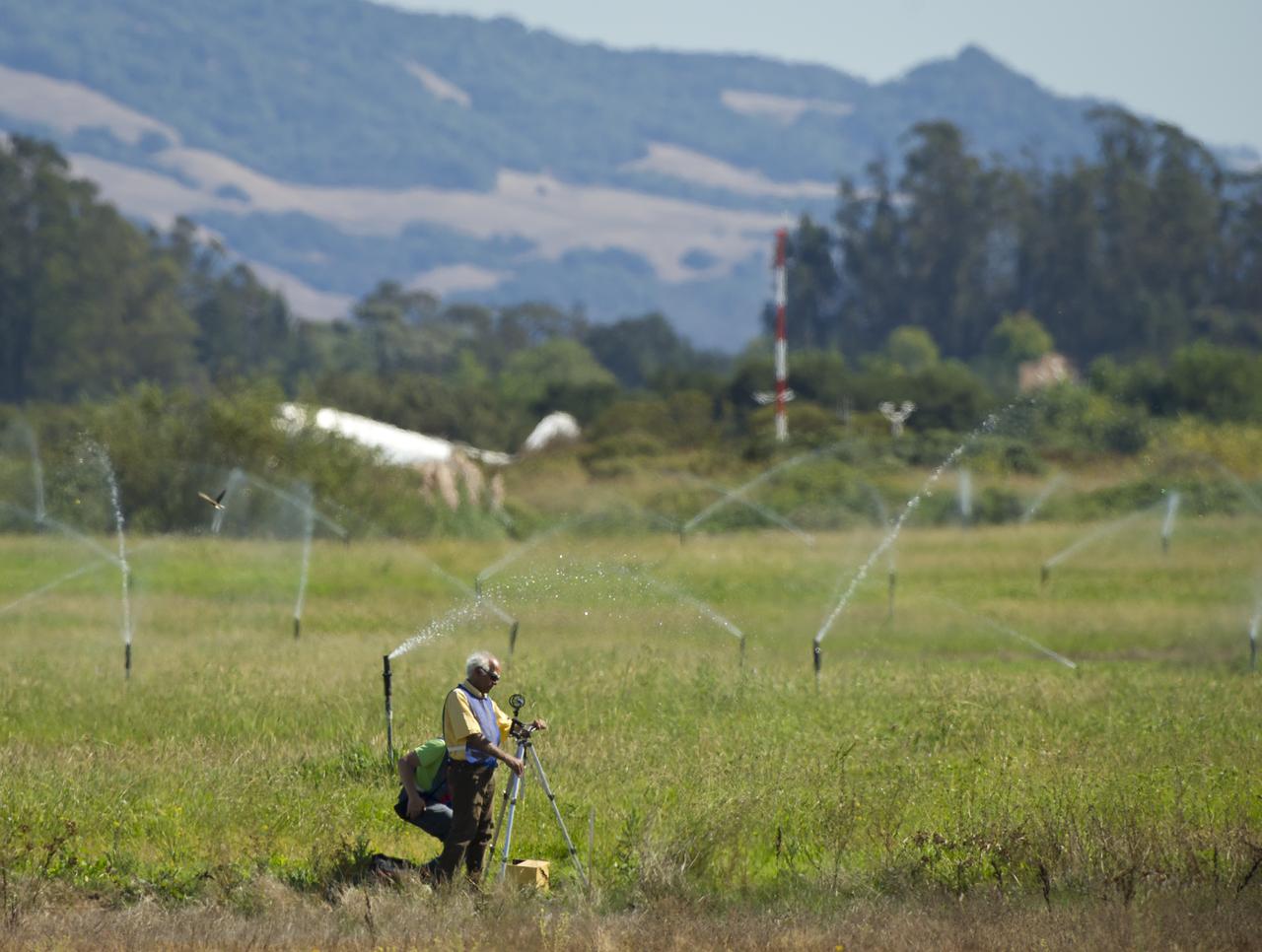
Support personnel prepare noise level measuring equipment along the runway for the 2011 Green Flight Challenge, sponsored by Google, at the Charles M. Schulz Sonoma County Airport in Santa Rosa, Calif. on Monday, Sept. 26, 2011. NASA and the Comparative Aircraft Flight Efficiency (CAFE) Foundation are having the challenge with the goal to advance technologies in fuel efficiency and reduced emissions with cleaner renewable fuels and electric aircraft. Photo Credit: (NASA/Bill Ingalls)
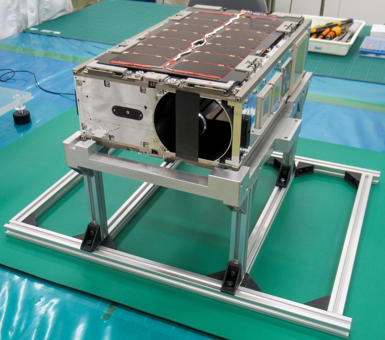
jsc2024e081750 (12/17/2024) --- ONboard Globe-Looking And Imaging Satellite (ONGLAISAT) is a 6U size CubeSat aiming for high signal-to-noise ratio image capture using Time Delay Integration (TDI) technology as its mission. ONGLAISAT is deployed from the International Space Station as part of the JEM Small Satellite Orbital Deployer-30 (J-SSOD-30) CubeSat deployment mission. Image courtesy of Space BD Inc.
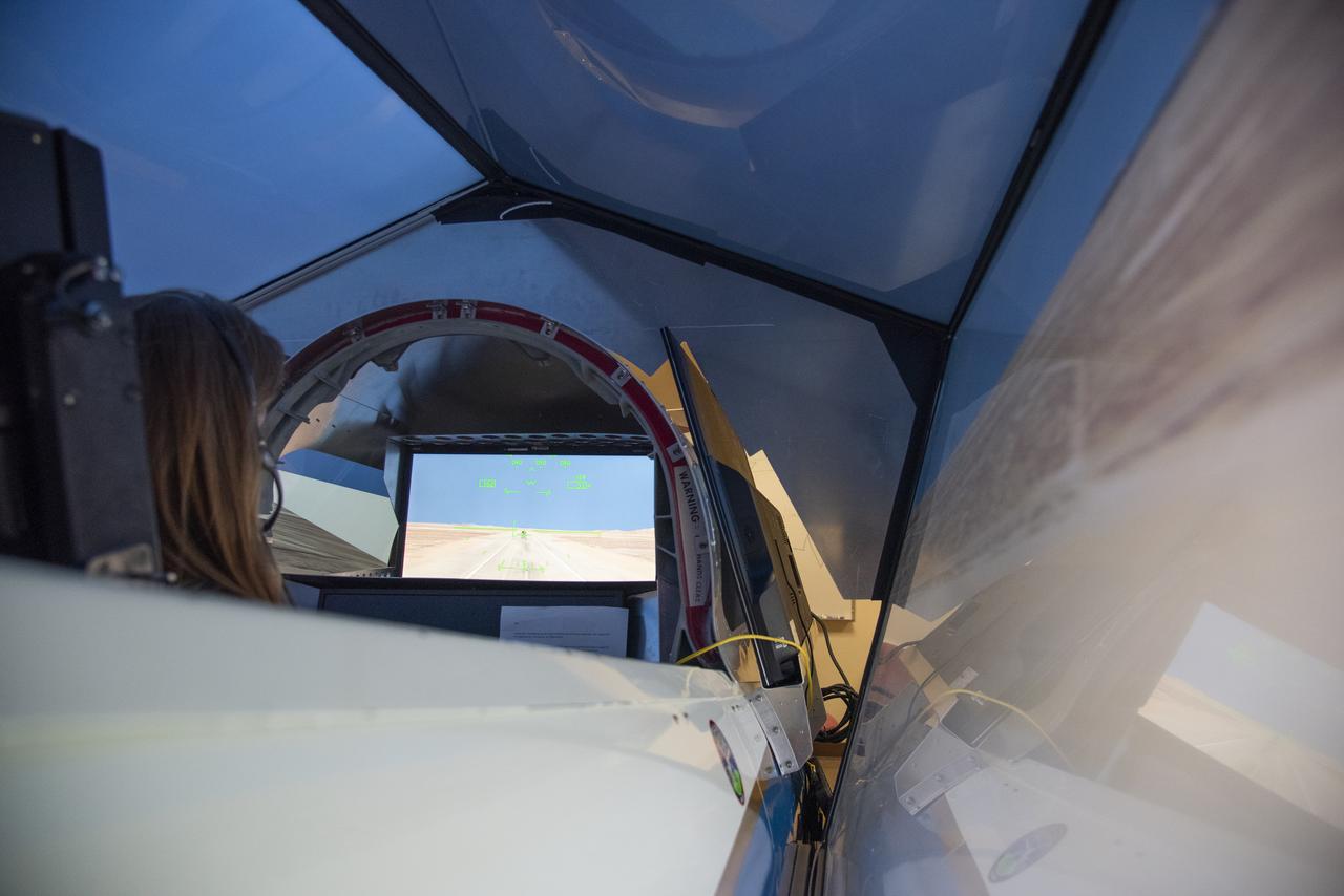
NASA's 2017 astronaut candidate Kayla Barron practices flying in an X-59 QueSST simulator at Armstrong Flight Research Center, in Southern California. The low boom flight demonstrator, X-59, being built at Lockheed Martin and was designed to fly at supersonic speeds over land without the loud noise of breaking the sound barrier and disturbing communities.
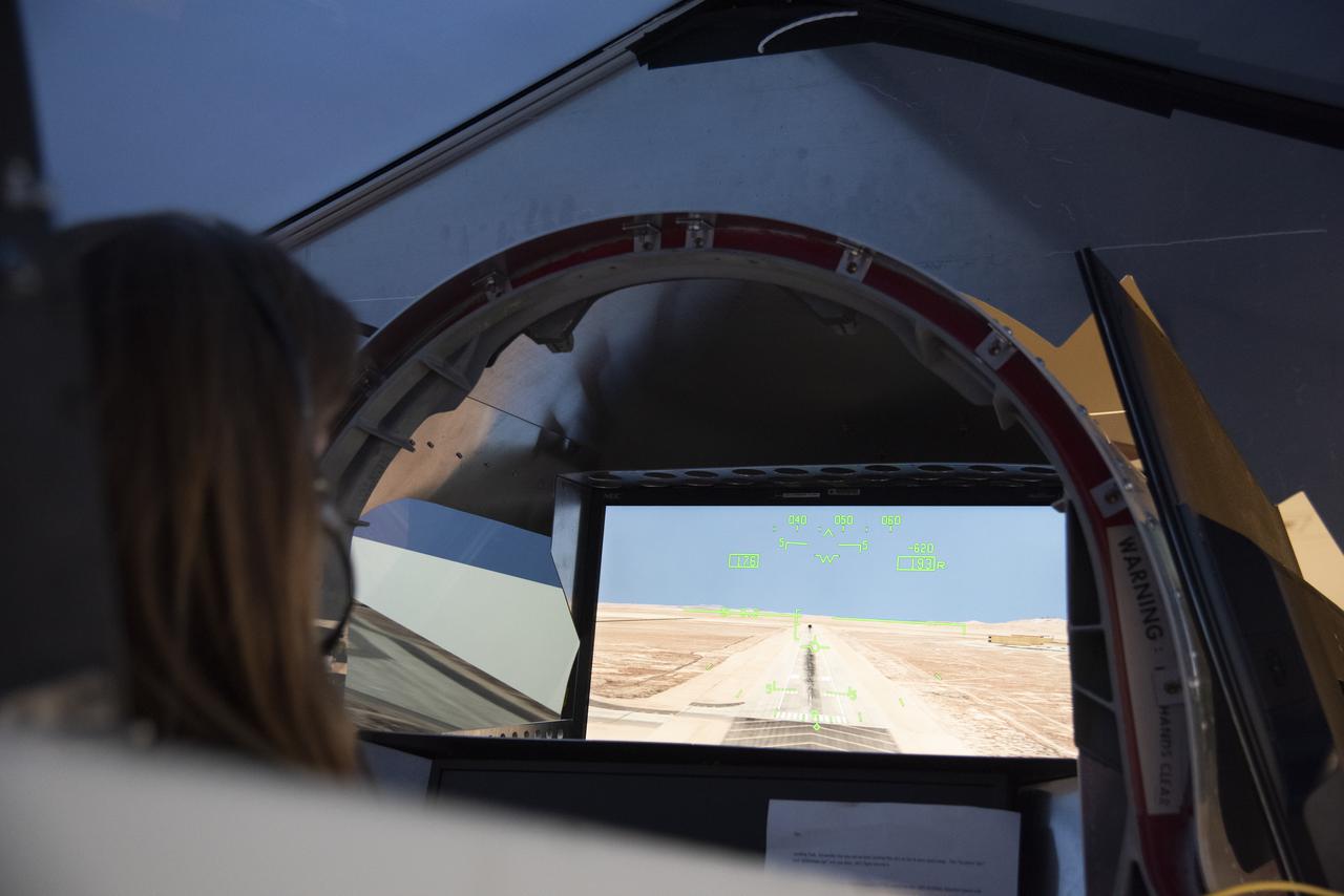
NASA's 2017 astronaut candidate Kayla Barron practices flying in an X-59 QueSST simulator at Armstrong Flight Research Center, in Southern California. The low boom flight demonstrator, X-59, being built at Lockheed Martin and was designed to fly at supersonic speeds over land without the loud noise of breaking the sound barrier and disturbing communities.
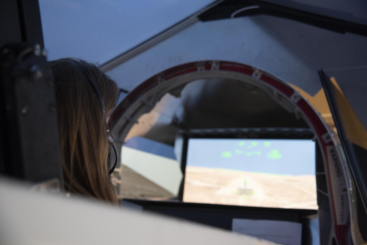
NASA's 2017 astronaut candidate Kayla Barron practices flying in an X-59 QueSST simulator at Armstrong Flight Research Center, in Southern California. The low boom flight demonstrator, X-59, being built at Lockheed Martin and was designed to fly at supersonic speeds over land without the loud noise of breaking the sound barrier and disturbing communities.