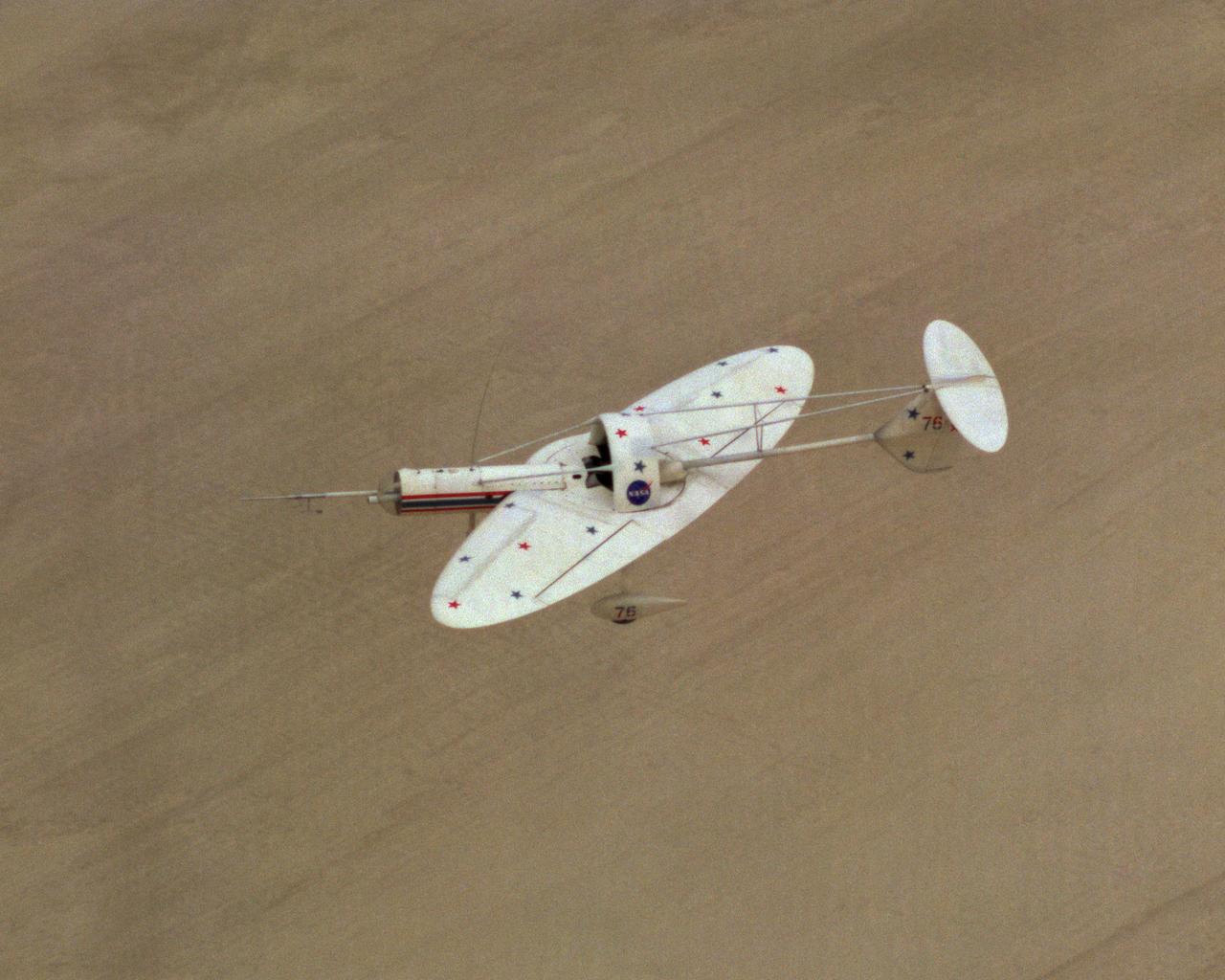
Oblique Wing Research Aircraft in flight
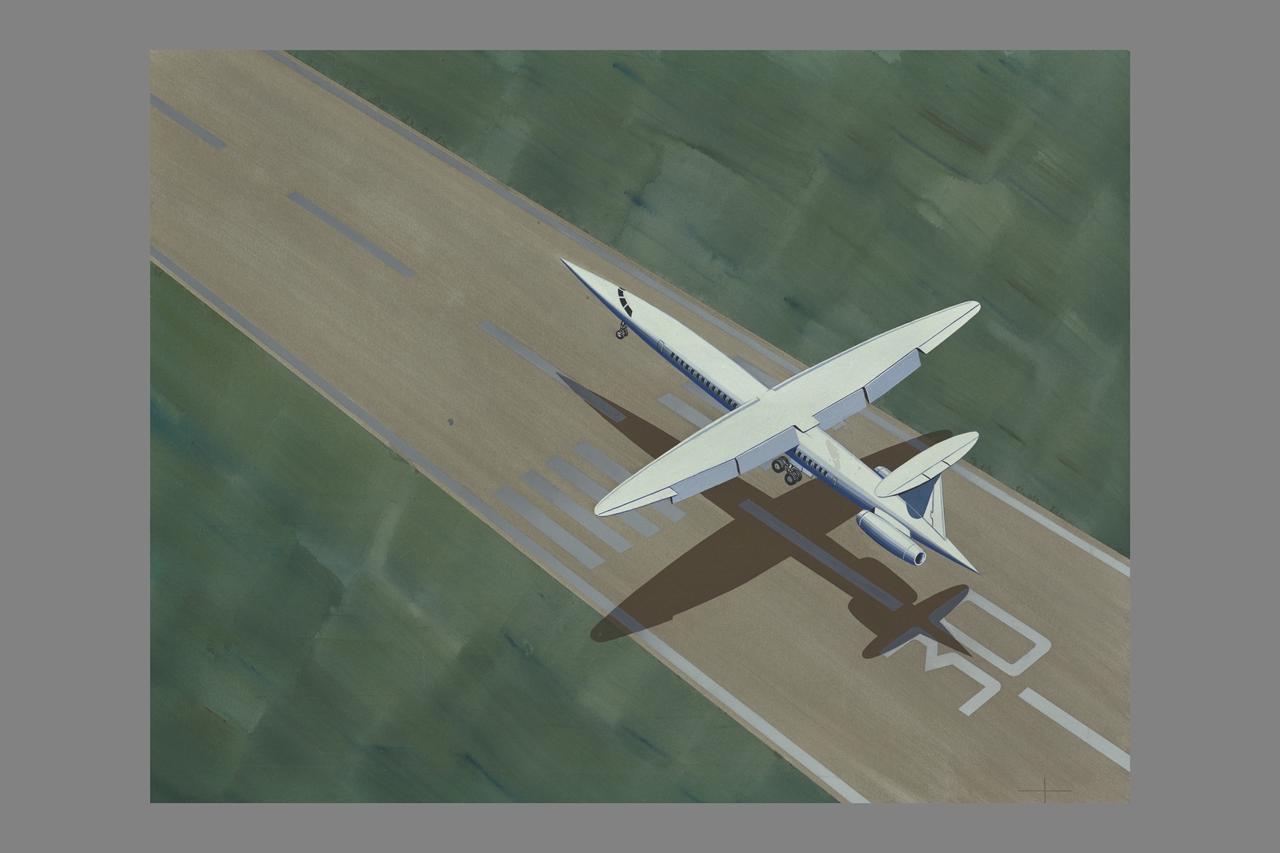
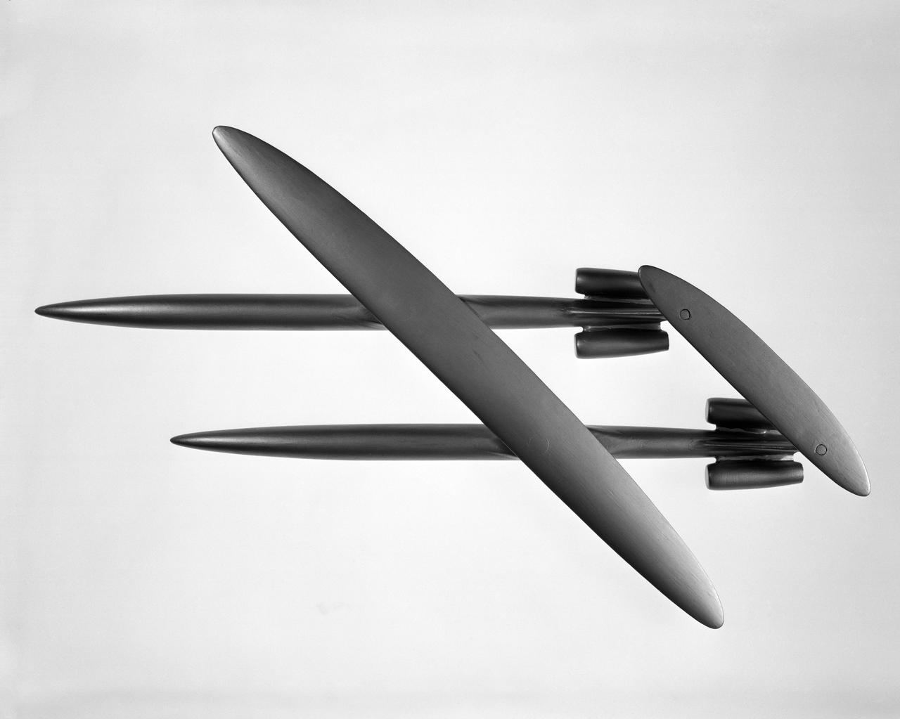
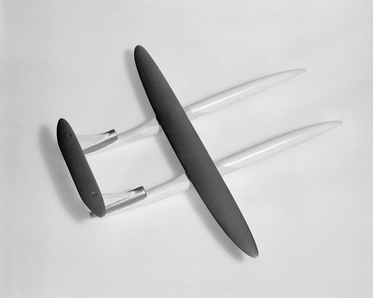
R.T. Jones Oblique Wing model: landing configuration
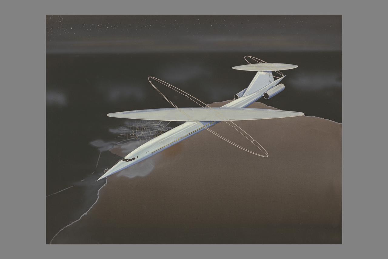
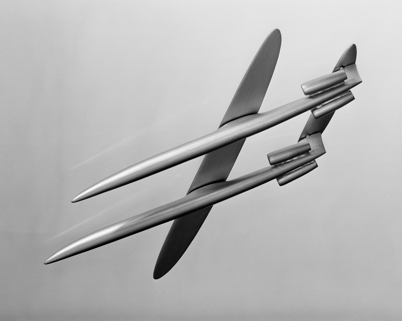
R.T. Jones Oblique Wing model: flight configuration
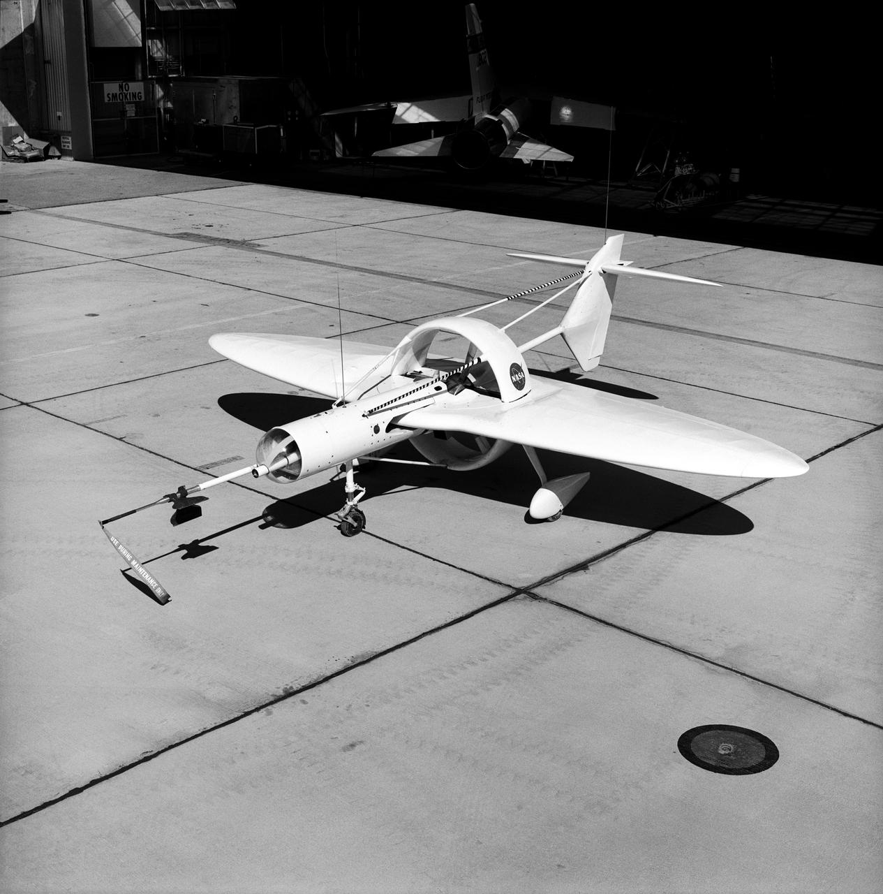
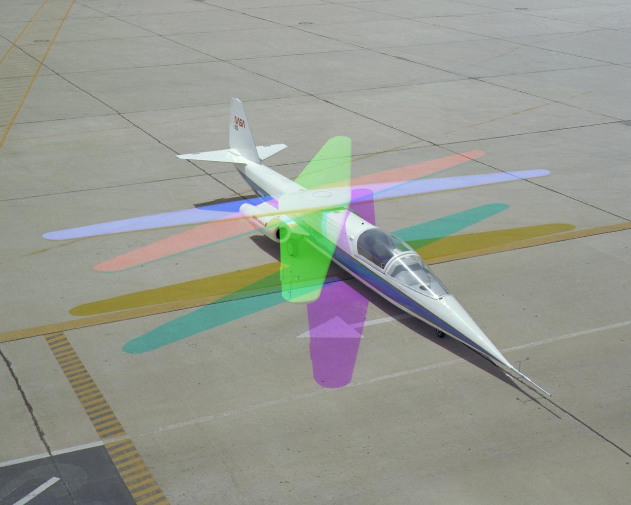
This 1976 photograph of the Oblique Wing Research Aircraft was taken in front of the NASA Flight Research Center hangar, located at Edwards Air Force Base, California. In the photograph the noseboom, pitot-static probe, and angles-of-attack and sideslip flow vanes(covered-up) are attached to the front of the vehicle. The clear nose dome for the television camera, and the shrouded propellor for the 90 horsepower engine are clearly seen.
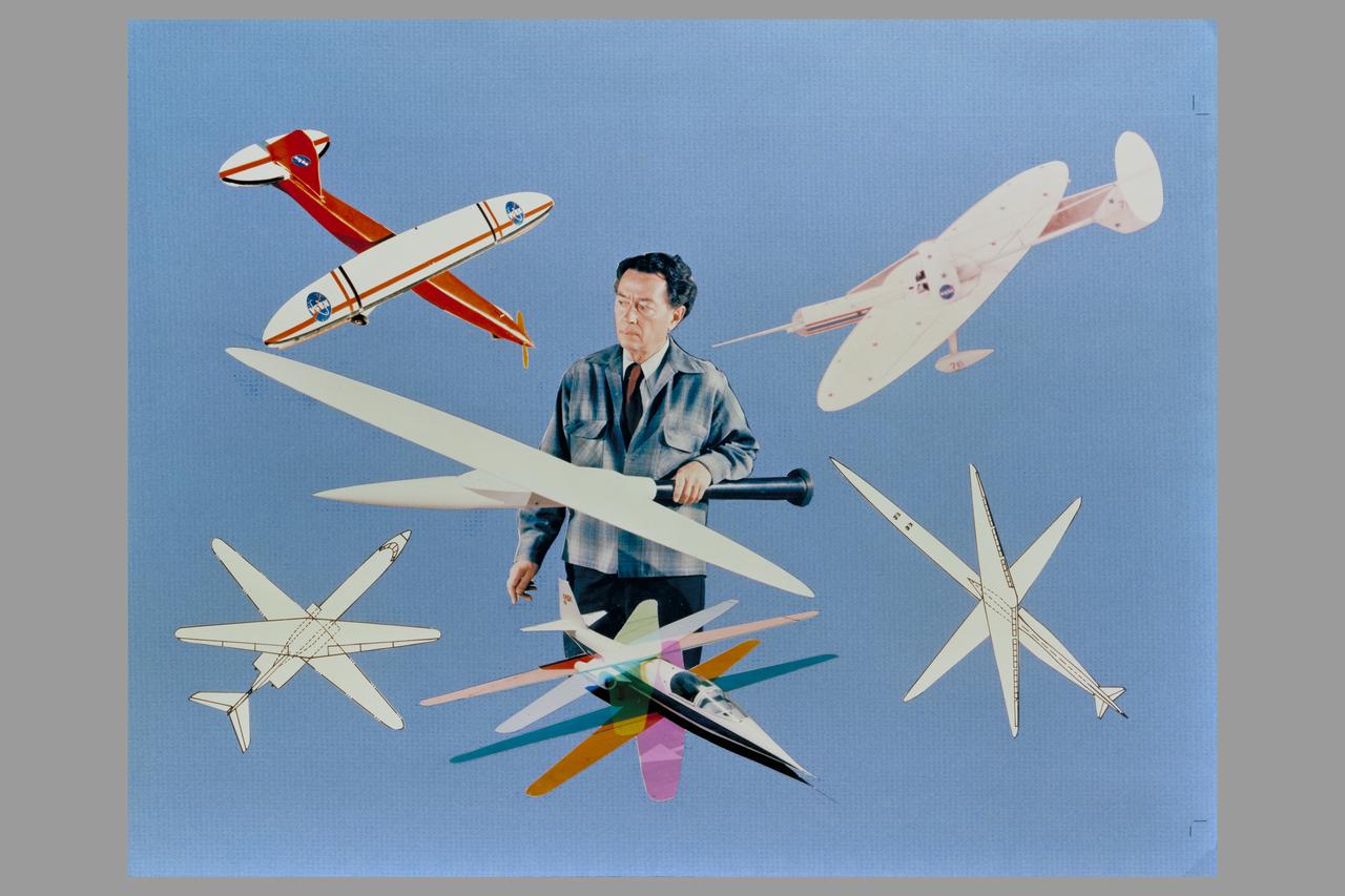
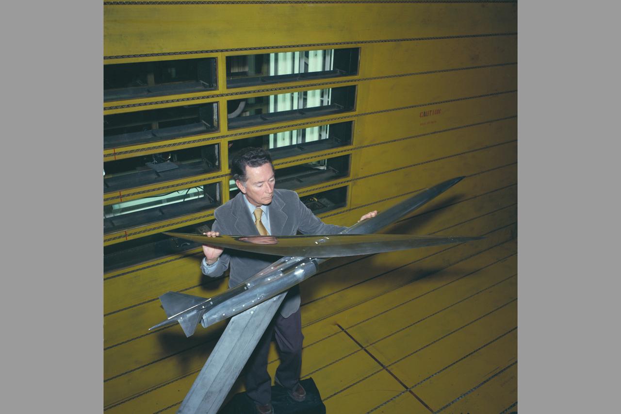
R.T. Jones w/ AD-1 Oblique Wing Models
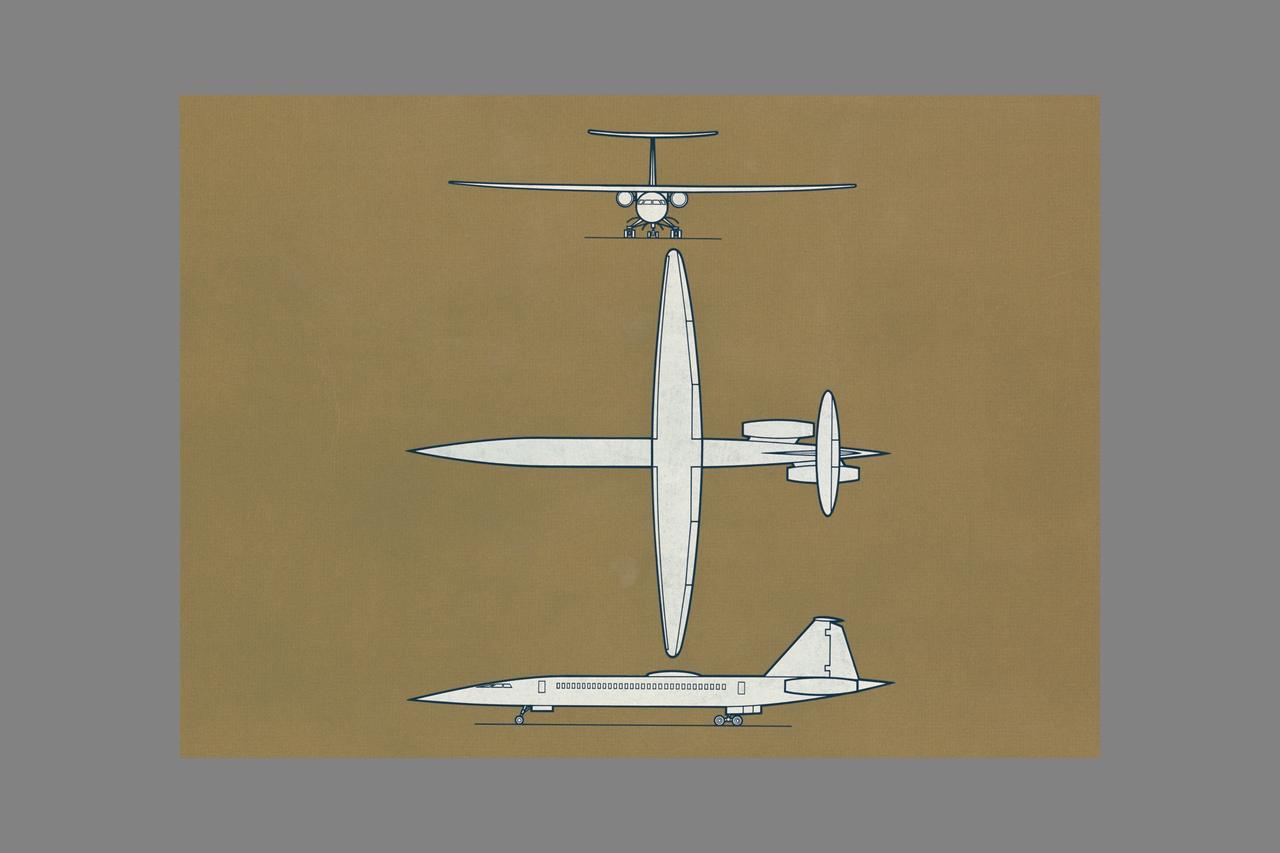
R.T. Jones Oblique Wing model: singal fuselage - 3 view artwork
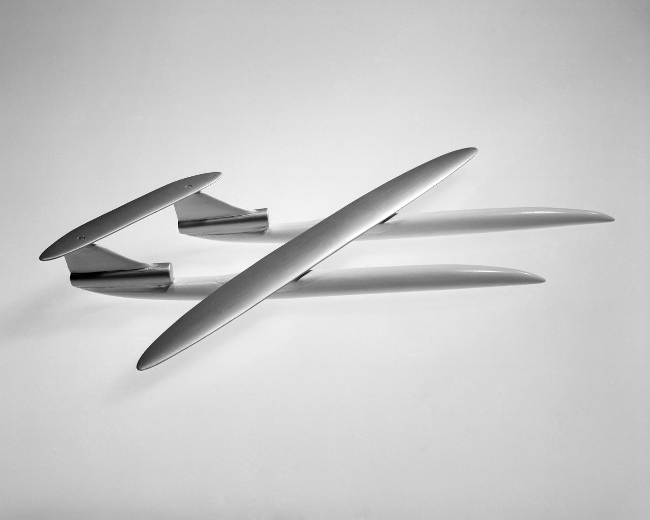
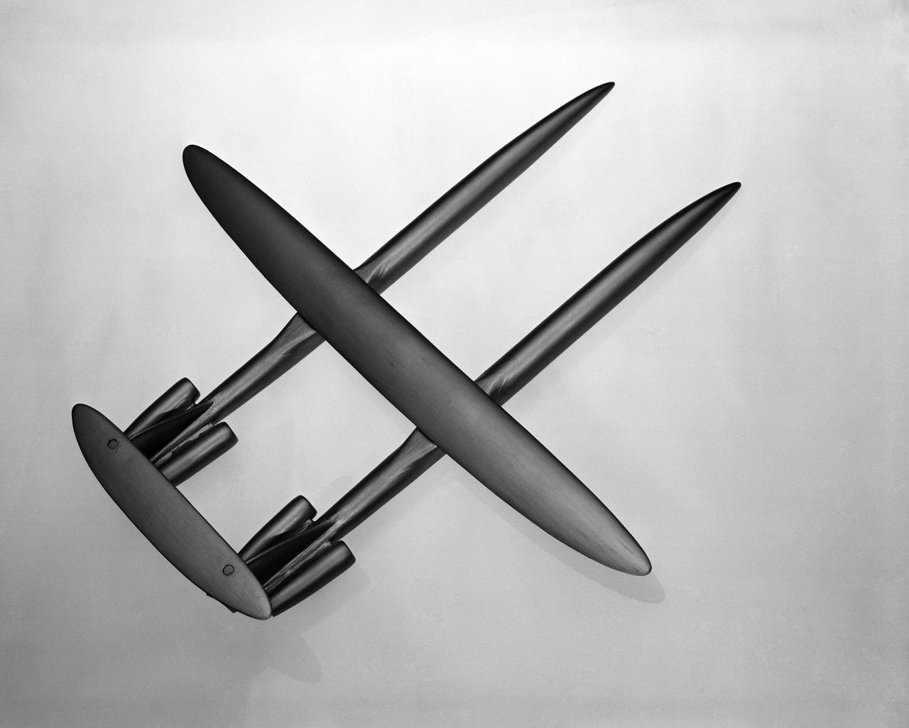
R.T. JONES OBLIQUE WING TRANSONIC TRANSPORT MODEL 2-BODY 'DOUBLE' FUSELAGE

R.T. JONES OBLIQUE WING TRANSONIC TRANSPORT MODEL 2-BODY 'DOUBLE' FUSELAGE

R.T. Jones with models
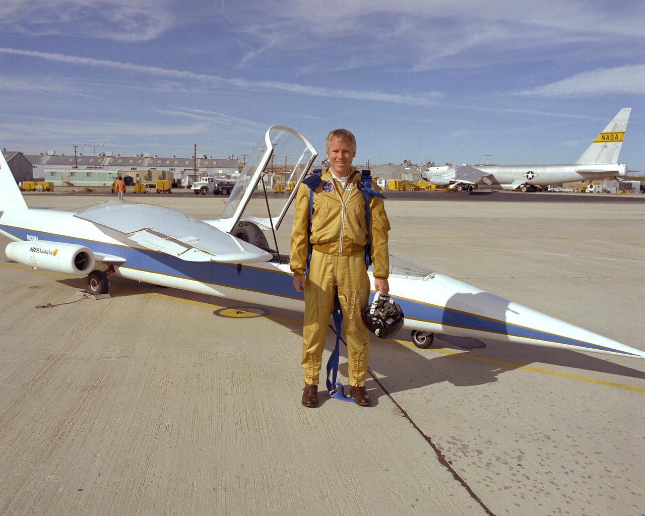
Research pilot Richard E. Gray, standing in front of the AD-1 Oblique Wing research aircraft.
OBLIQUE WING TRANSONIC TRANSPORT MODEL: DR. R. T. JONES' CONCEPT-STRAIGHT WING CONFIGURATION
OBLIQUE WING TRANSONIC TRANSPORT MODEL: DR. R. T. JONES' CONCEPT-STRAIGHT WING CONFIGURATION
OBLIQUE WING TRANSONIC TRANSPORT MODEL: DR. R. T. JONES' CONCEPT-STRAIGHT WING CONFIGURATION
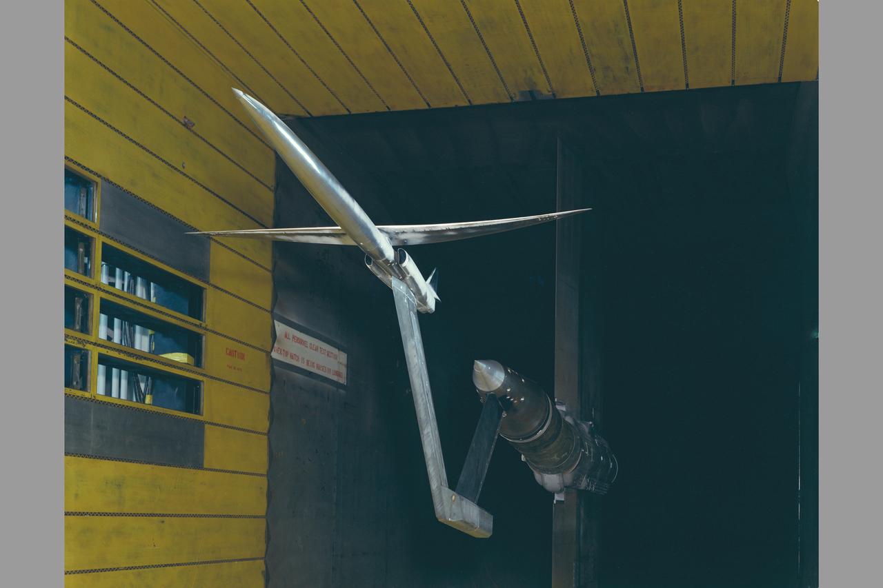
Oblique wing in 11ft. wind tunnel Test 11-026.
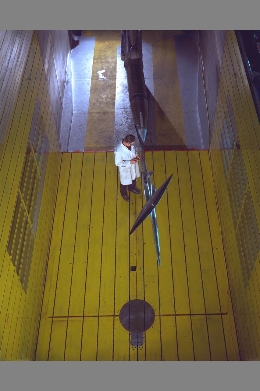
Practical Oblique Wing Test-026) in 11ft w.t. overhead view with technician
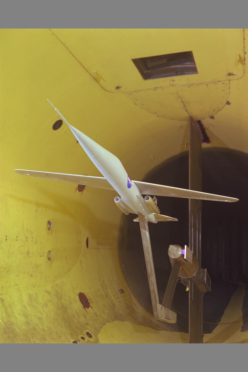
Aerodynamics Low cost Oblique Wing Model in 12ft w.t.
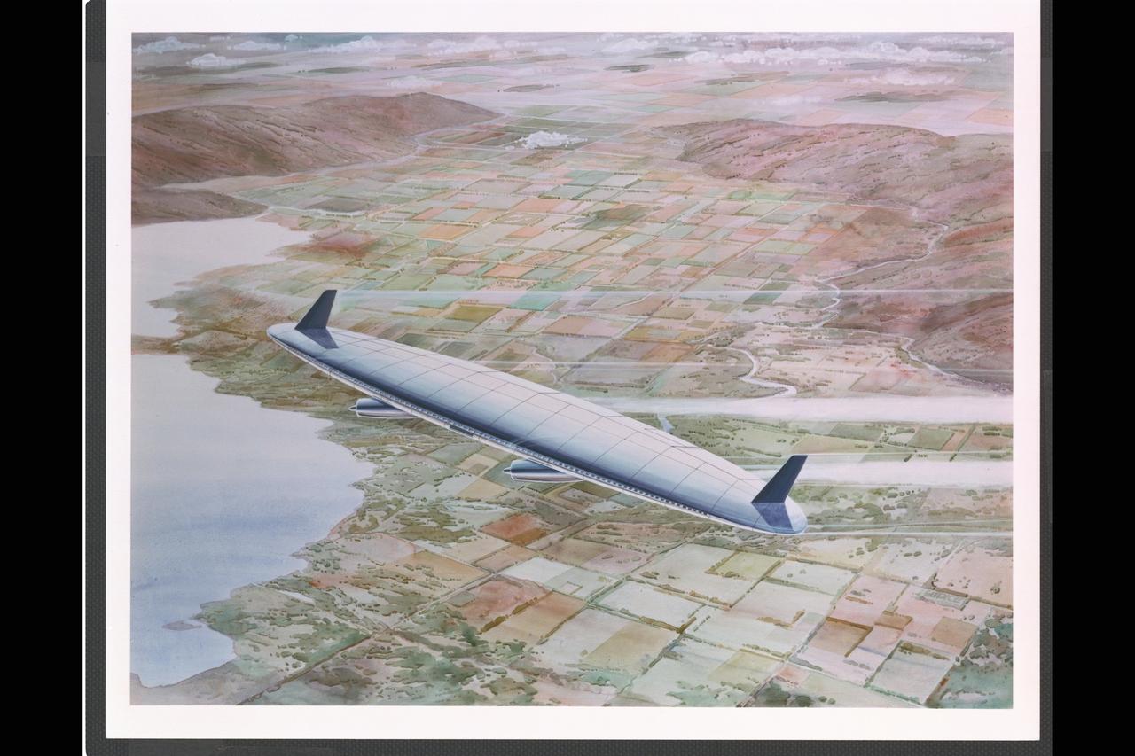
Artist: Rick Guidice Flying Oblique Wing designed by R.T. Jones Artwork
Oblique wing in 11ft. wind tunnel with R. T. Jones. Test-11-026.
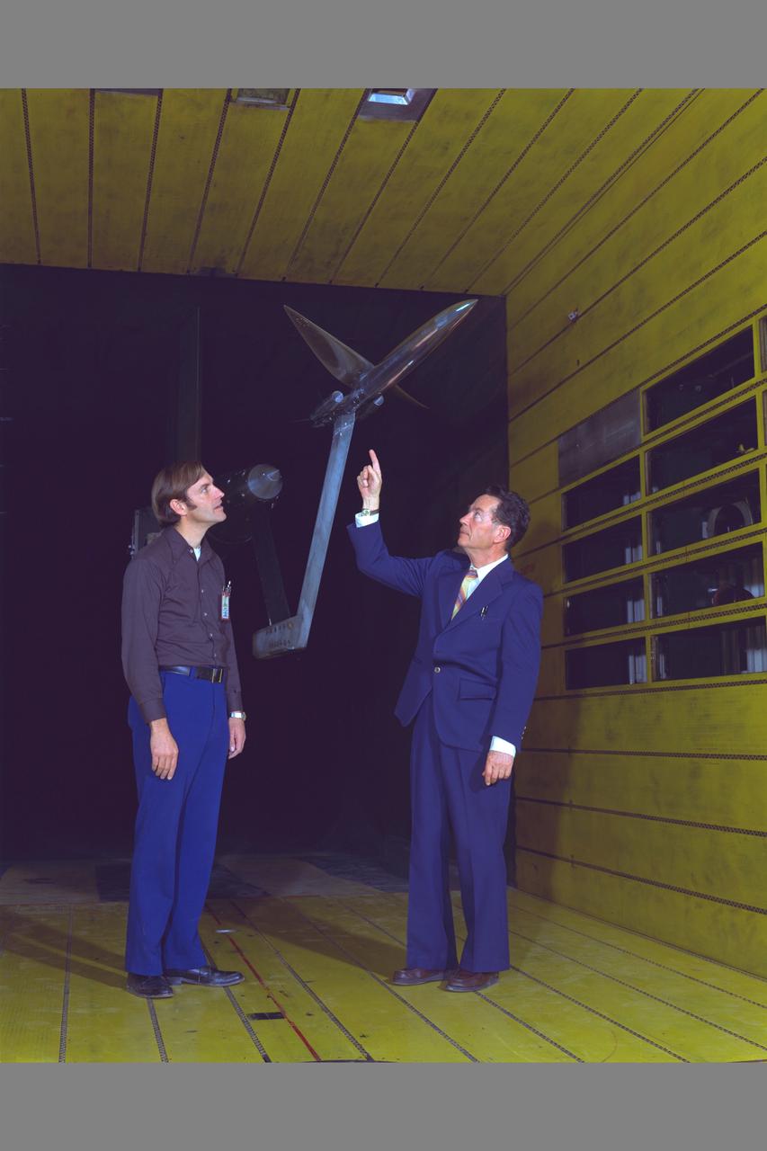
Practical Oblique Wing Test-026) in 11ft w.t. with R. T. Jones and test engineer

Oblique wing in 11ft. wind tunnel with R. T. Jones. Test 11-026.
OBLIQUE WING TRANSONIC TRANSPORT MODEL (2-BODY FUSELAGE) DR. R.T. JONES' CONCEPT
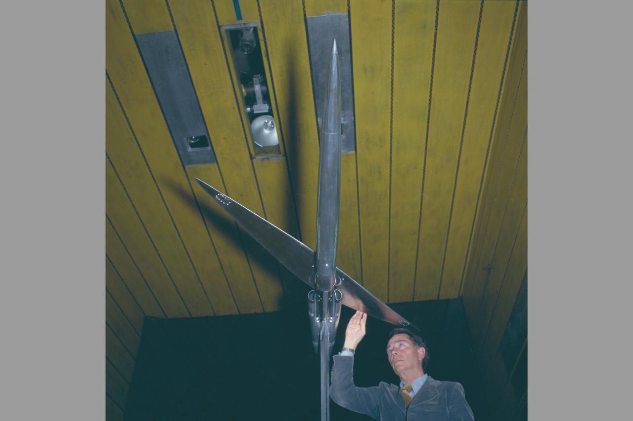
Oblique wing in 11ft. wind tunnel with R. T. Jones. Test 11-026.
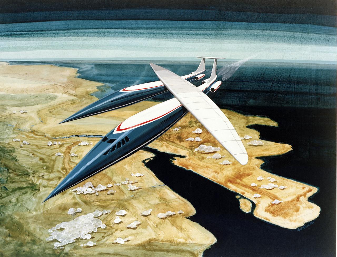
ARTWORK BY RICK GUIDICE OBLIQUE WING TRANSONIC TRANSPORT MODEL: DR ROBERT T JONES 2-BODY 'DOUBLE' FUSELAGE CONCEPT IN FLIGHT

Oblique Wing model mounted in 11ft W. T. with R. T. Jones, Designer/Engineer. The asymmetrical design allows the plane to fly much faster, yet consume the same fuel and generate less noise.
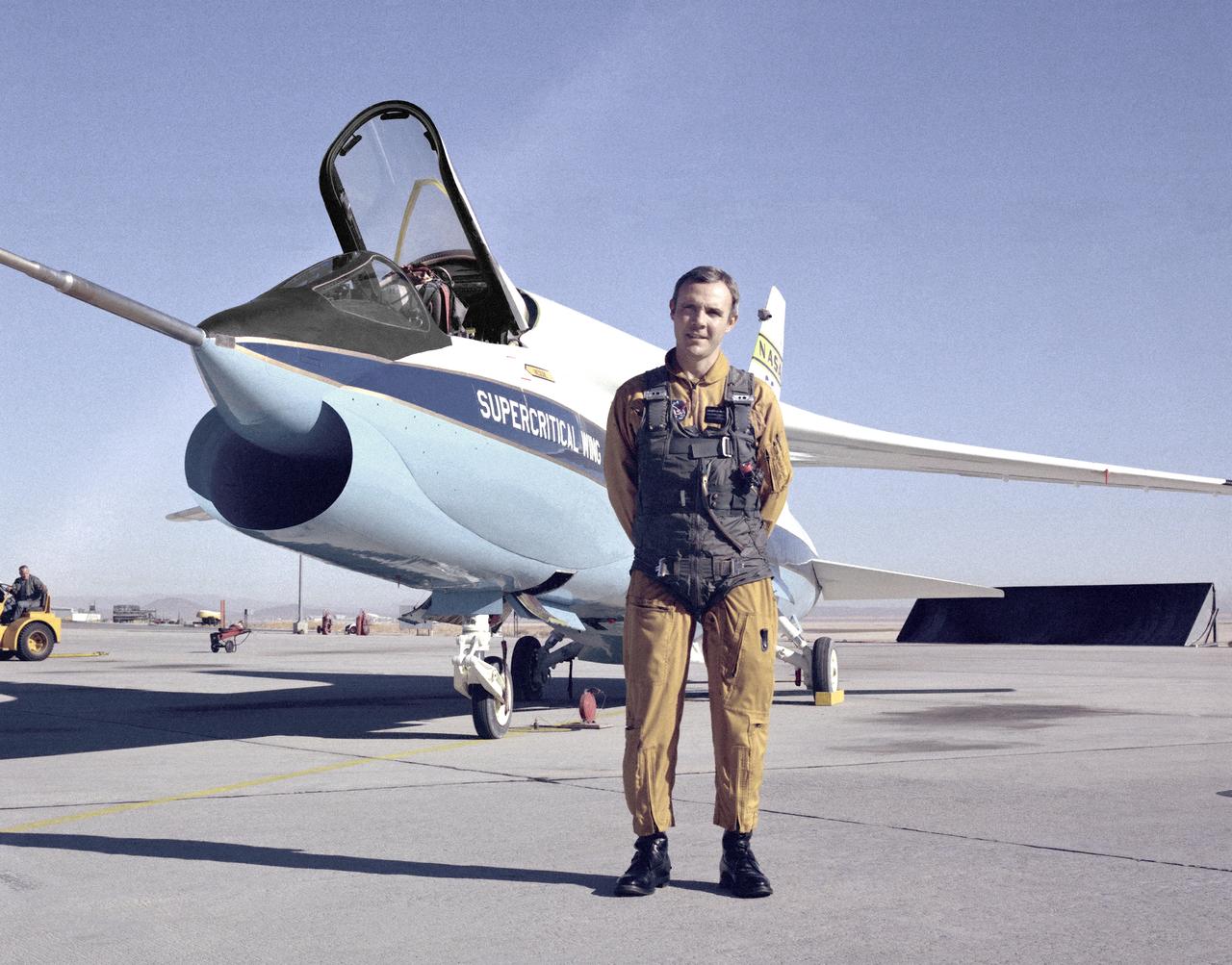
A Vought F-8A Crusader was selected by NASA as the testbed aircraft (designated TF-8A) to install an experimental Supercritical Wing (SCW) in place of the conventional wing. The unique design of the Supercritical Wing reduces the effect of shock waves on the upper surface near Mach 1, which in turn reduces drag. In this photograph the TF-8A Crusader with Supercritical Wing is shown on the ramp with project pilot Tom McMurtry standing beside it. McMurtry received NASA's Exceptional Service Medal for his work on the F-8 SCW aircraft. He also flew the AD-1, F-15 Digital Electronic Engine Control, the KC-130 winglets, the F-8 Digital Fly-By-Wire and other flight research aircraft including the remotely piloted 720 Controlled Impact Demonstration and sub-scale F-15 research projects. In addition, McMurtry was the 747 co-pilot for the Shuttle Approach and Landing Tests and made the last glide flight in the X-24B. McMurtry was Dryden’s Director for Flight Operations from 1986 to 1998, when he became Associate Director for Operations at NASA Dryden. In 1982, McMurtry received the Iven C. Kincheloe Award from the Society of Experimental Test Pilots for his contributions as project pilot on the AD-1 Oblique Wing program. In 1998 he was named as one of the honorees at the Lancaster, Calif., ninth Aerospace Walk of Honor ceremonies. In 1999 he was awarded the NASA Distinguished Service Medal. He retired in 1999 after a distinguished career as pilot and manager at Dryden that began in 1967.
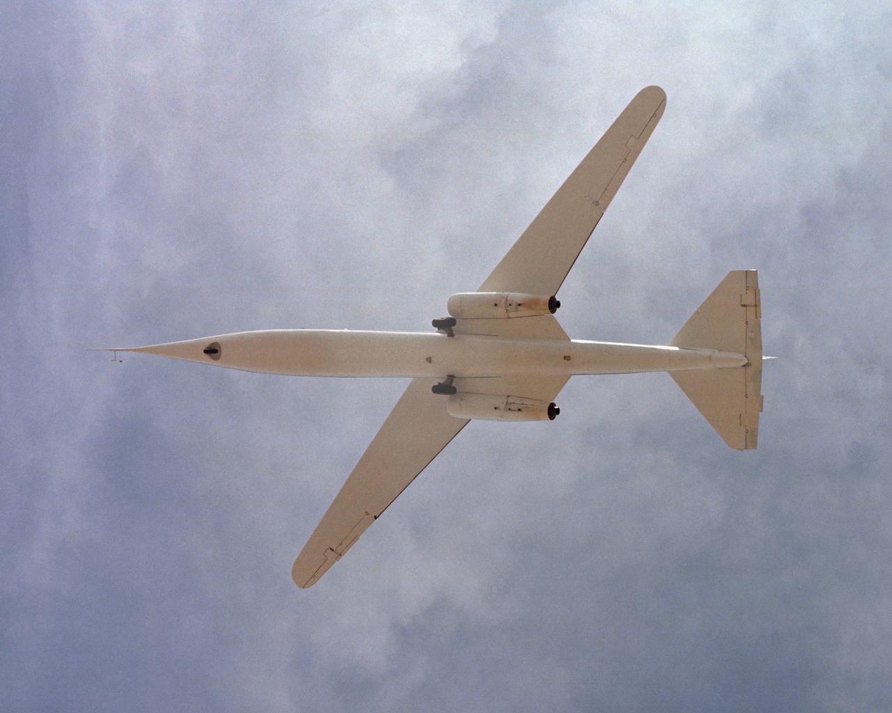
The AD-1 aircraft with its wing swept. Visible are the twin jet engines that powered the aircraft and the fixed landing gear.
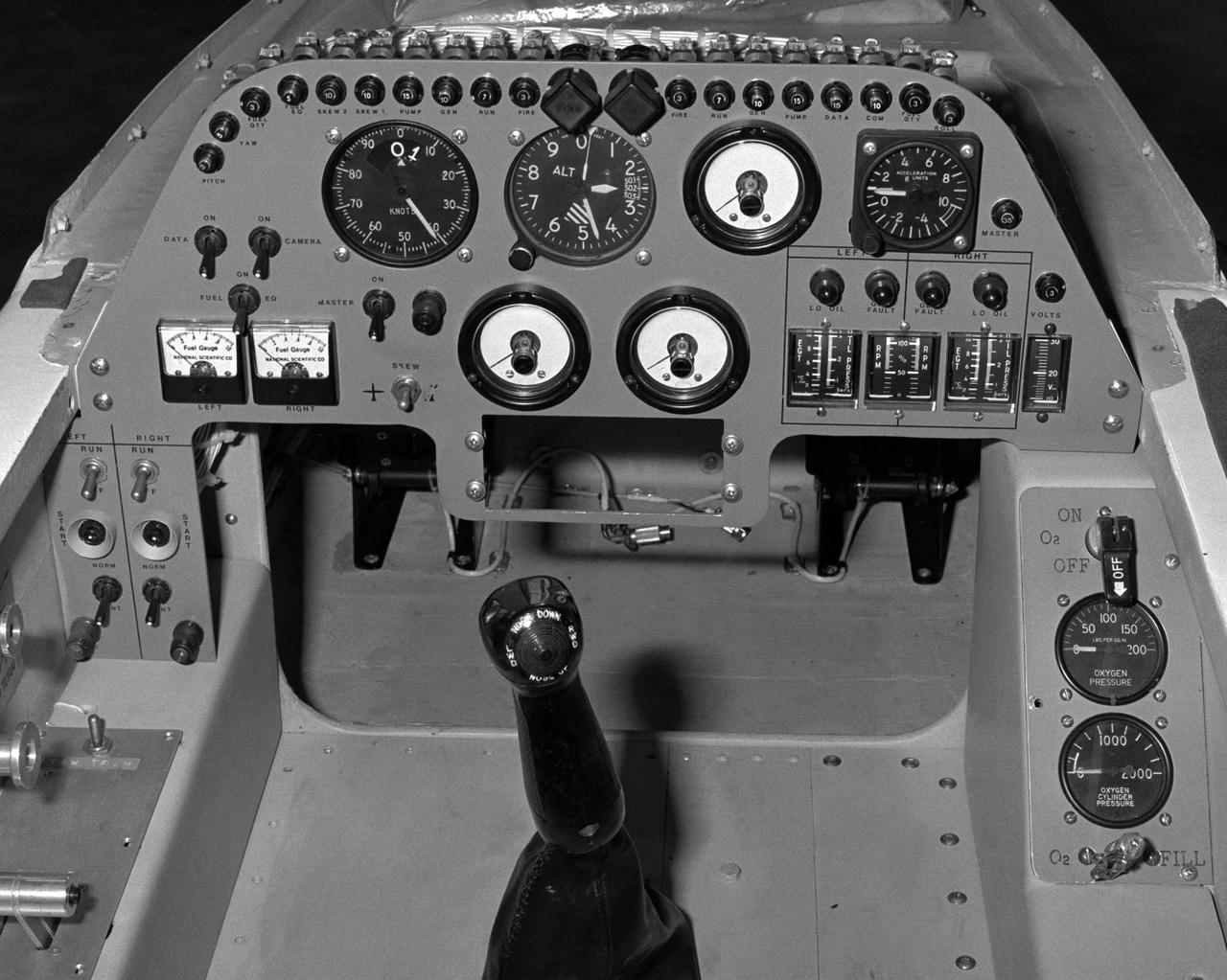
The cockpit and instrument panel of the AD-1 aircraft. Due to the small size of the AD-1, instrumentation was limited and the cockpit was cramped.
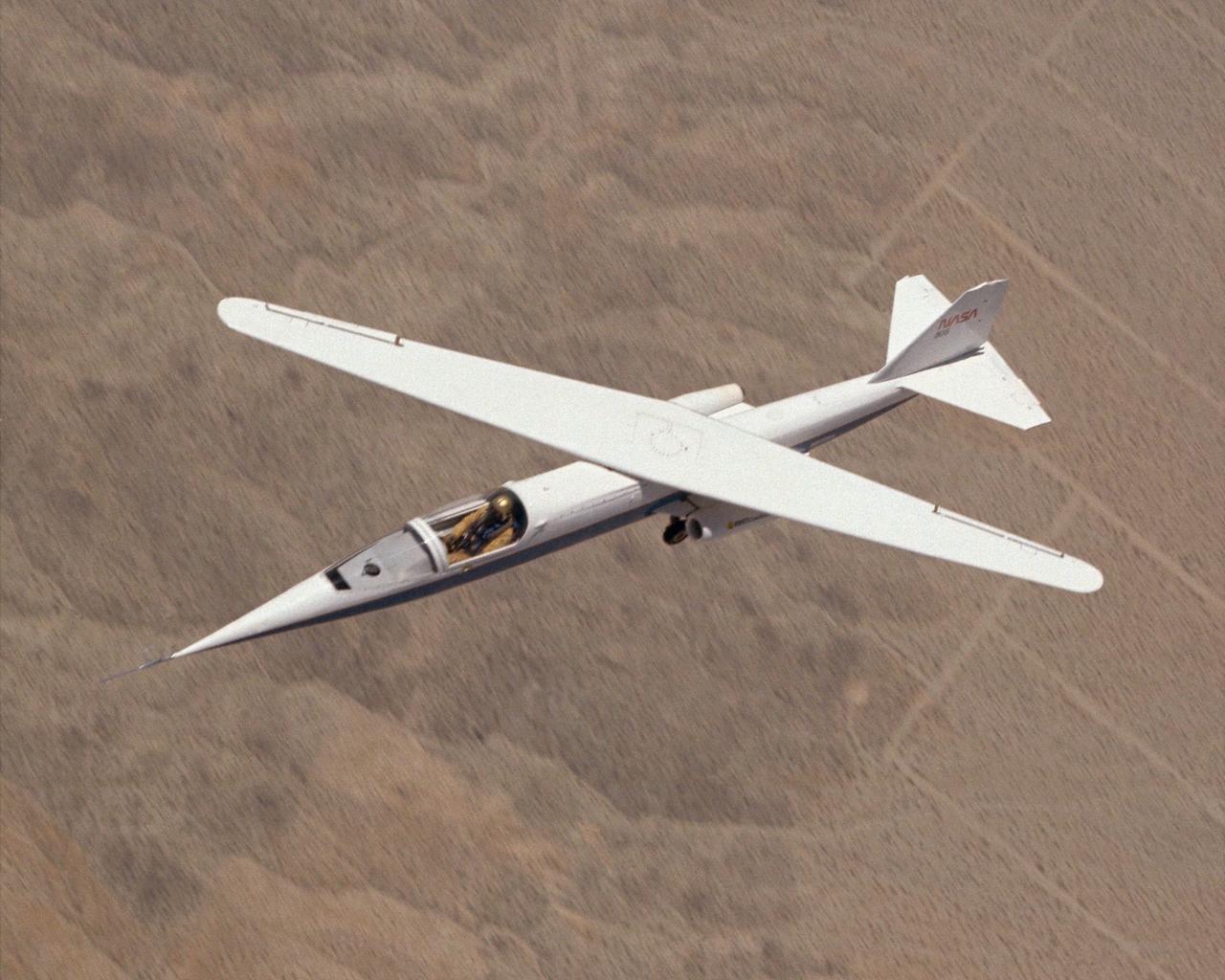
AD-1 in flight. Flight #30. The AD-1 aircraft in flight with its wing swept at 60 degrees, the maximum sweep angle.
Multiple exposure image showing wing movement on AD-1.

S118-E-09467 (19 Aug. 2007) --- The International Space Station is featured in this image photographed by a STS-118 crewmember on the Space Shuttle Endeavour following the undocking of the two spacecraft, which occurred at 6:56 a.m. (CDT) on Aug. 19, 2007. The image was acquired through one of the crew cabin windows, looking back over the length of the shuttle. Endeavour had undocked from the station, and the crew had begun late inspection of the orbiter's Thermal Protection System (wing leading edges, nosecap, and belly tiles) prior to landing. The late inspection is performed using sensors mounted on the Orbiter Boom Sensor System (OBSS) in order to assess whether micrometeorite or orbiting debris impacts had compromised the Thermal Protection System of the shuttle while it was docked with the station. This oblique image was acquired almost one hour after late inspection activities had begun. The sensor head of the OBSS is visible at top left. The entirety of the orbital outpost is visible at bottom center, set against the backdrop of the Ionian Sea approximately 330 kilometers below it. Other visible features of the southeastern Mediterranean region include the toe and heel features of Italy's "boot" at lower left, and the western coastlines of Albania and Greece extend across the center. Further towards the horizon, the Aegean and Black Seas are also visible.

S118-E-09469 (19 Aug. 2007) --- The International Space Station is featured in this image photographed by a STS-118 crewmember on the Space Shuttle Endeavour following the undocking of the two spacecraft, which occurred at 6:56 a.m. (CDT) on Aug. 19, 2007. The image was acquired through one of the crew cabin windows, looking back over the length of the shuttle. Endeavour had undocked from the station, and the crew had begun late inspection of the orbiter's Thermal Protection System (wing leading edges, nosecap, and belly tiles) prior to landing. The late inspection is performed using sensors mounted on the Orbiter Boom Sensor System (OBSS) in order to assess whether micrometeorite or orbiting debris impacts had compromised the Thermal Protection System of the shuttle while it was docked with the station. This oblique image was acquired almost one hour after late inspection activities had begun. The sensor head of the OBSS is visible at top left. The entirety of the orbital outpost is visible at bottom center, set against the backdrop of the Ionian Sea approximately 330 kilometers below it. Other visible features of the southeastern Mediterranean region include the toe and heel features of Italy's "boot" at lower left, and the western coastlines of Albania and Greece extend across the center. Further towards the horizon, the Aegean and Black Seas are also visible.