
Patrick Chan demonstrates one way that the Fiber Optic Sensing System is used by bending a fiber with a 3D representation of the fiber’s shape as it bends.
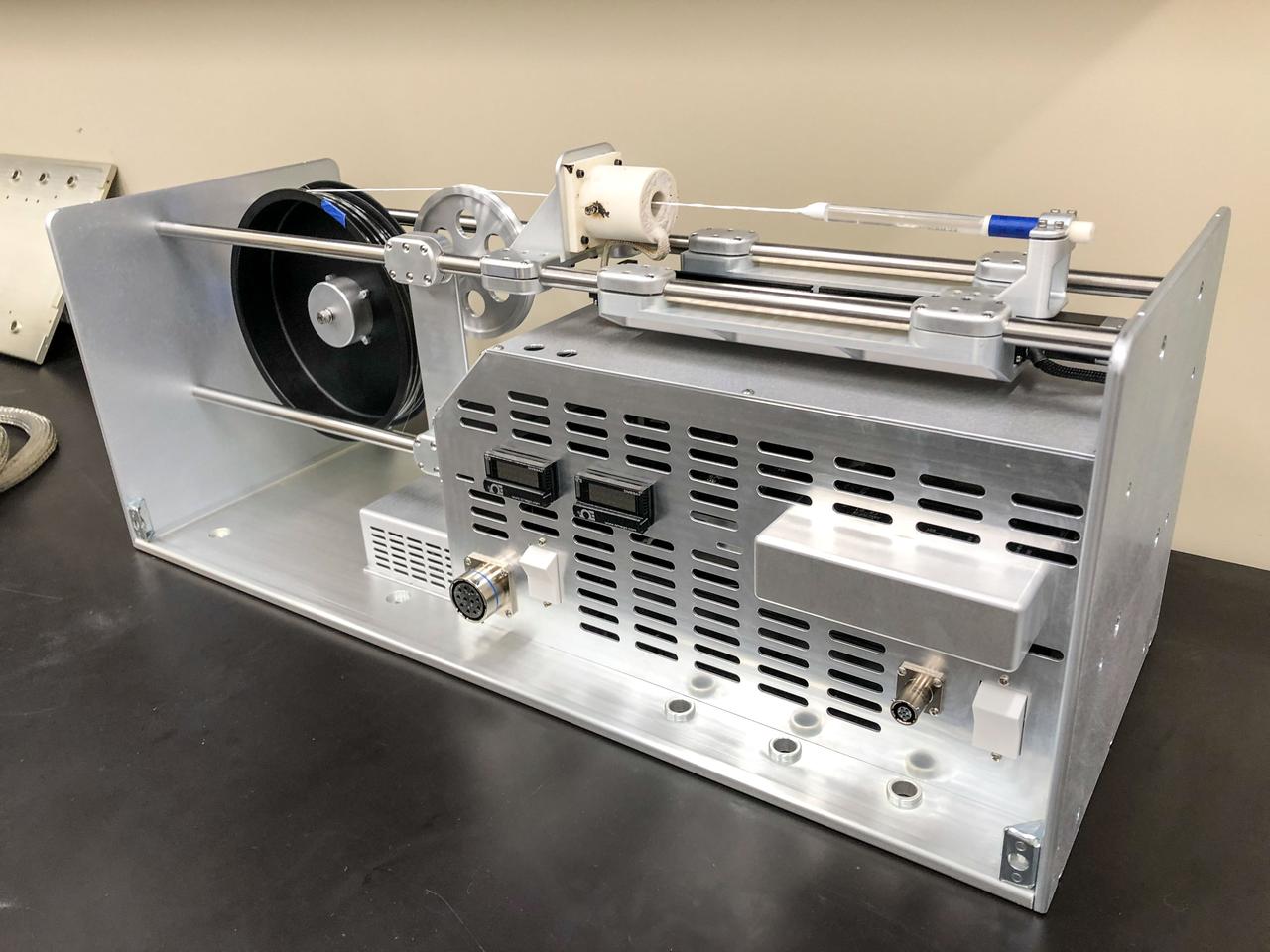
jsc2019e048247 (9/28/2018) — Preflight imagery of the Fiber Optic Production hardware. Physical Optics Corporation’s (POC’s) Fiber Optic Production investigation will create optical fibers with high commercial value aboard the International Space Station (ISS)and will operate within the Microgravity Science Glovebox (MSG).
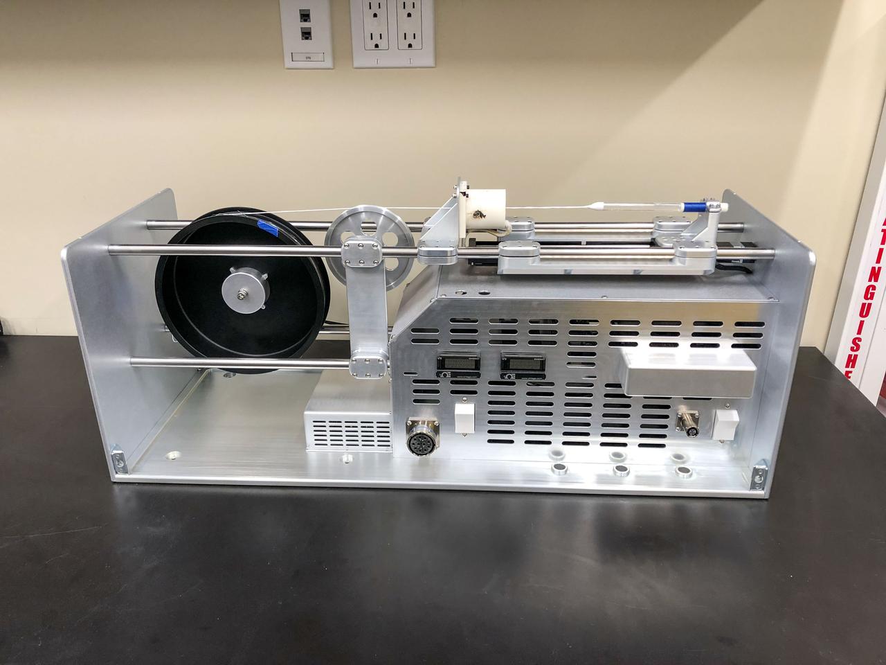
jsc2019e048246 (9/28/2018) — Preflight imagery of the Fiber Optic Production hardware. Physical Optics Corporation’s (POC’s) Fiber Optic Production investigation will create optical fibers with high commercial value aboard the International Space Station (ISS)and will operate within the Microgravity Science Glovebox (MSG).
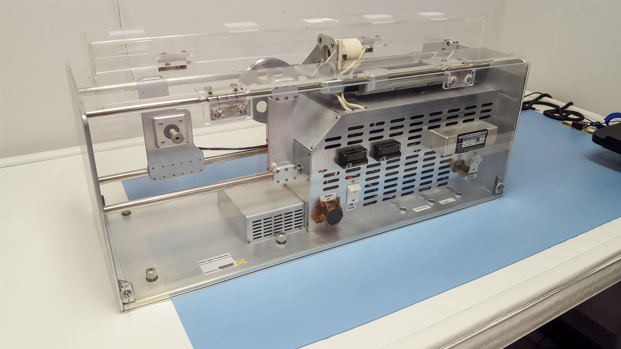
jsc2019e048245 (3/6/2019) — Preflight imagery of the Fiber Optic Production hardware. Physical Optics Corporation’s (POC’s) Fiber Optic Production investigation will create optical fibers with high commercial value aboard the International Space Station (ISS)and will operate within the Microgravity Science Glovebox (MSG).
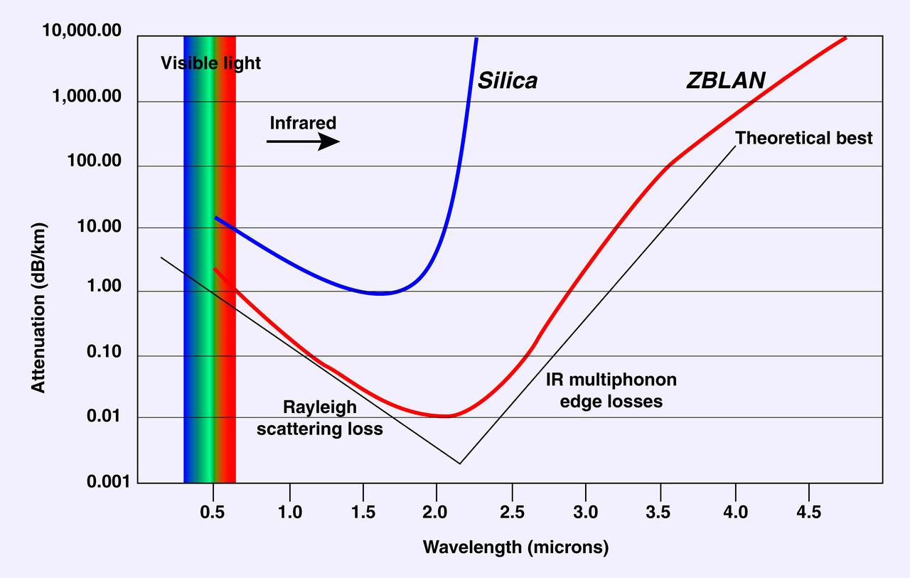
This graph depicts the increased signal quality possible with optical fibers made from ZBLAN, a family of heavy-metal fluoride glasses (fluorine combined zirconium, barium, lanthanum, aluminum, and sodium) as compared to silica fibers. NASA is conducting research on pulling ZBLAN fibers in the low-g environment of space to prevent crystallization that limits ZBLAN's usefulness in optical fiber-based communications. In the graph, a line closer to the black theoretical maximum line is better. Photo credit: NASA/Marshall Space Flight Center

Shideh Naderi works on designing the electronics for the next generation Fiber Optic Sensing System.
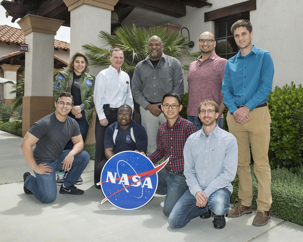
The Fiber Optic Sensing System team includes in the front from left Nick Finks, Ryan Warner, Patrick Chan and Paul Bean. In the back row from left are Shideh Naderi, Jeff Bauer, Allen Parker, Frank Pena and Nathan Perreau. Lance Richards, Anthony Piazza and Phil Hamory are current FOSS team members who are not pictured.
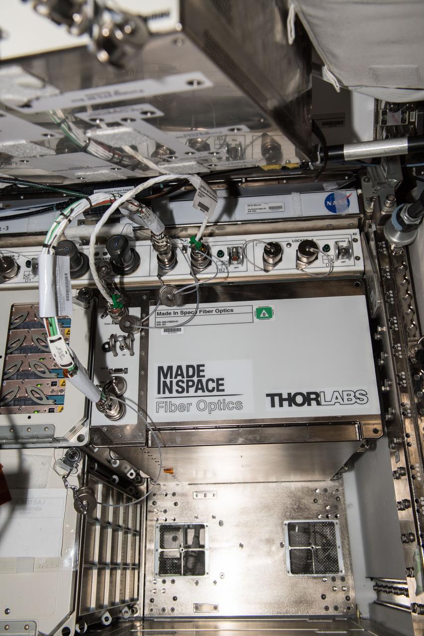
iss054e005568 (12-26-2017) --- View of the Made In Space Fiber Optics Locker installed in ExPRESS (Expedite the Processing of Experiments to Space Station) Rack 7. The Optical Fiber Production in Microgravity (Made In Space Fiber Optics) investigation demonstrates the merits of manufacturing fiber optic filaments in microgravity.
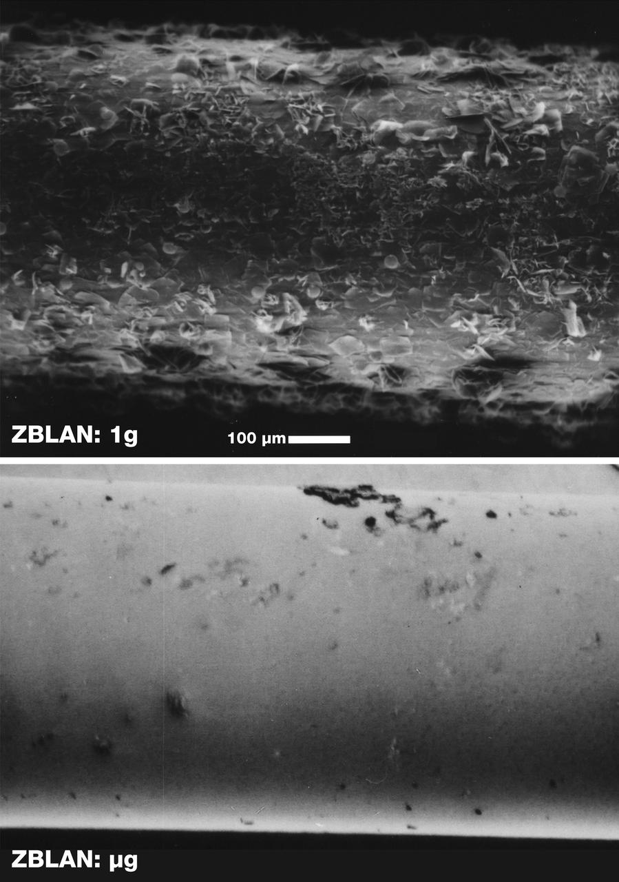
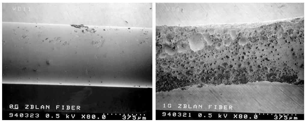
Scarning electron microscope images of the surface of ZBLAN fibers pulled in microgravity (ug) and on Earth (1g) show the crystallization that normally occurs in ground-based processing. The face of each crystal will reflect or refract a portion of the optical signal, thus degrading its quality. NASA is conducting research on pulling ZBLAN fibers in the low-g environment of space to prevent crystallization that limits ZBLAN's usefulness in optical fiber-based communications. ZBLAN is a heavy-metal fluoride glass that shows exdeptional promise for high-throughput communications with infrared lasers. Photo credit: NASA/Marshall Space Flight Center
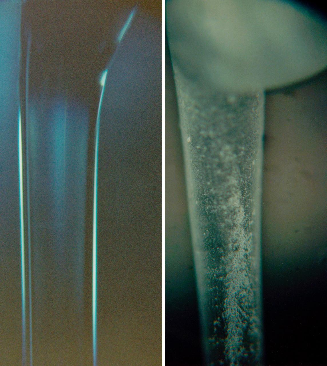
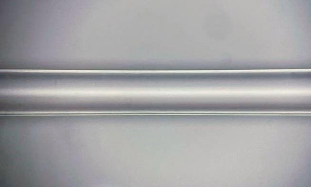
Sections of ZBLAN fibers pulled in a conventional 1-g process (right) and in experiments aboard NASA's KC-135 low-gravity aircraft (left). The rough surface of the 1-g fiber indicates surface defects that would scatter an optical signal and greatly degrade its quality. ZBLAN is part of the family of heavy-metal fluoride glasses (fluorine combined zirconium, barium, lanthanum, aluminum, and sodium). NASA is conducting research on pulling ZBLAN fibers in the low-g environment of space to prevent crystallization that limits ZBLAN's usefulness in optical fiber-based communications. ZBLAN is a heavy-metal fluoride glass that shows exceptional promise for high-throughput communications with infrared lasers. Photo credit: NASA/Marshall Space Flight Center
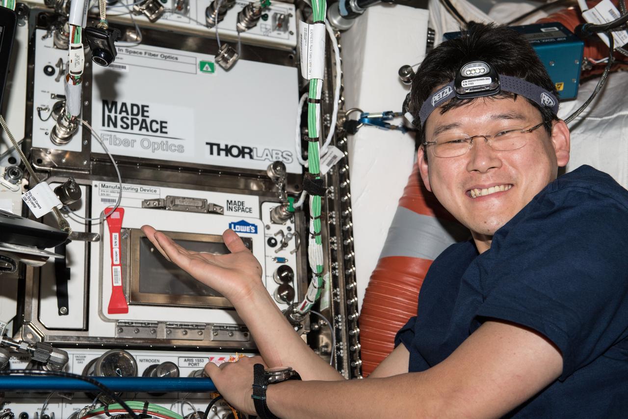
iss054e005575 (12-26-2017) --- Japan Aerospace Exploration Agency (JAXA) astronaut Norishige Kanai poses for a photo with the installed Made in Space Fiber Optics Locker and the re-installed Additive Manufacturing Facility (AMF) Manufacturing Device (ManD). Photo was taken in the Destiny U.S. Laboratory abord the International Space Station (ISS). The Optical Fiber Production in Microgravity (Made In Space Fiber Optics) investigation demonstrates the merits of manufacturing fiber optic filaments in microgravity.
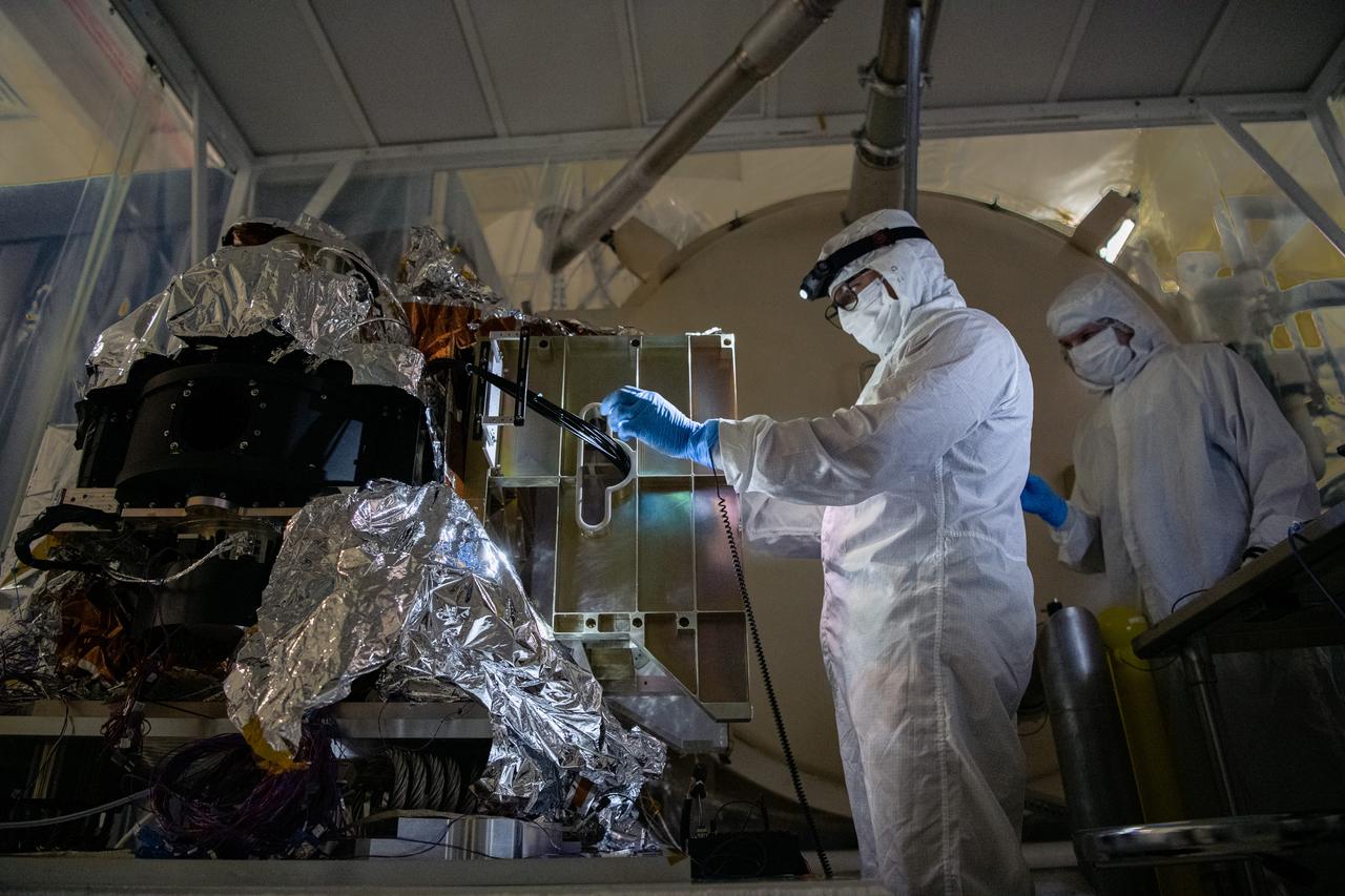
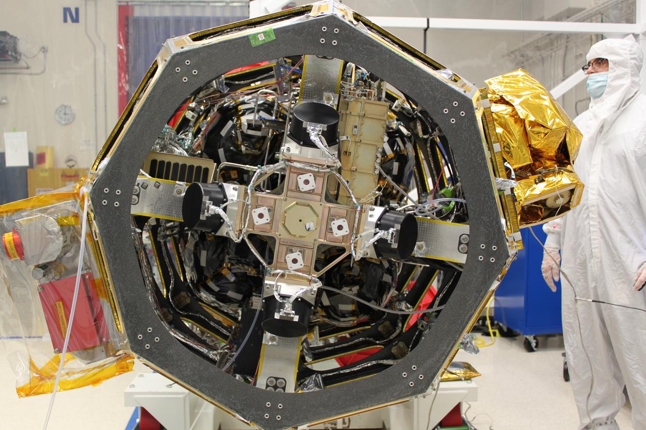
Alejandro Rodriguez Perez and Joe Thomes, members of the fiber optic & photonic team, configure the Ocean Color Instrument (OCI) Engineering Test Unit (ETU) Shortwave Infrared (SWIR) Detector Asembly and Multi-lens Array (MLA) fibers for thermal testing. OCI is a highly advanced optical spectrometer that will be used to measure properties of light over portions of the electromagnetic spectrum. It will enable continuous measurement of light at finer wavelength resolution than previous NASA satellite sensors, extending key system ocean color data records for climate studies. OCI is PACE's (Plankton, Aerosol, Cloud, ocean Ecosystem) primary sensor built at Goddard Space Flight Center in Greenbelt, MD.
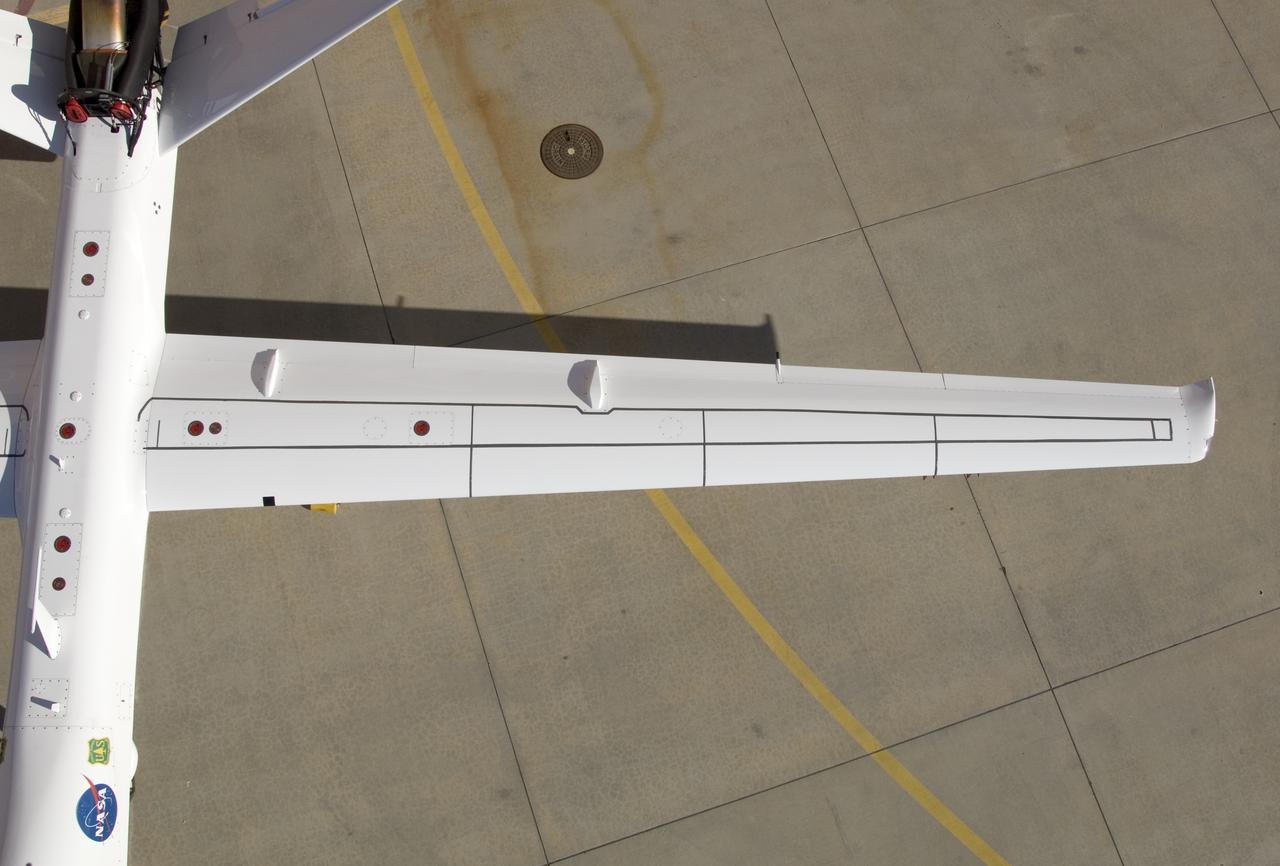
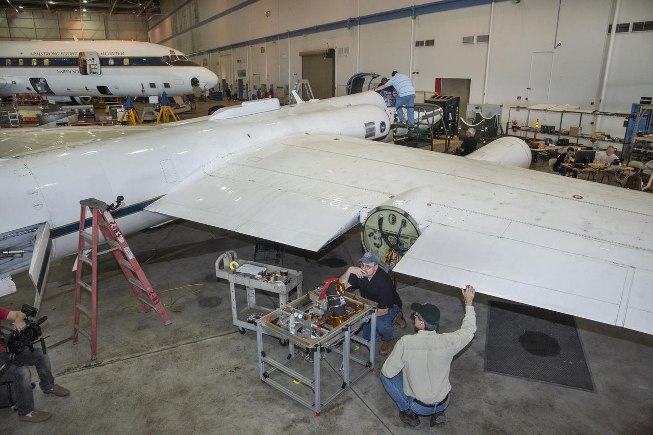
Although the new fiber optic sensors on the Ikhana, which are located on fibers that are the diameter of a human hair, are not visible, the sealant used to cover them can be seen in this view from above the left wing. NASA Dryden Flight Research Center is evaluating an advanced fiber optic-based sensing technology installed on the wings of NASA's Ikhana aircraft. The fiber optic system measures and displays the shape of the aircraft's wings in flight. There are other potential safety applications for the technology, such as vehicle structural health monitoring. If an aircraft structure can be monitored with sensors and a computer can manipulate flight control surfaces to compensate for stresses on the wings, structural control can be established to prevent situations that might otherwise result in a loss of control.
NASA engineer Larry Hudson and Ikhana ground crew member James Smith work on a ground validation test with new fiber optic sensors that led to validation flights on the Ikhana aircraft. NASA Dryden Flight Research Center is evaluating an advanced fiber optic-based sensing technology installed on the wings of NASA's Ikhana aircraft. The fiber optic system measures and displays the shape of the aircraft's wings in flight. There are other potential safety applications for the technology, such as vehicle structural health monitoring. If an aircraft structure can be monitored with sensors and a computer can manipulate flight control surfaces to compensate for stresses on the wings, structural control can be established to prevent situations that might otherwise result in a loss of control.
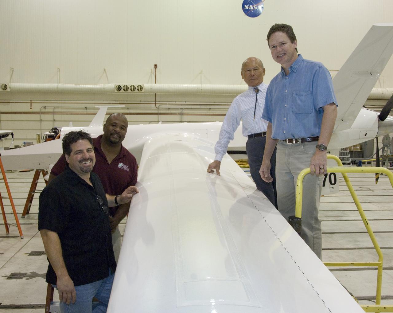
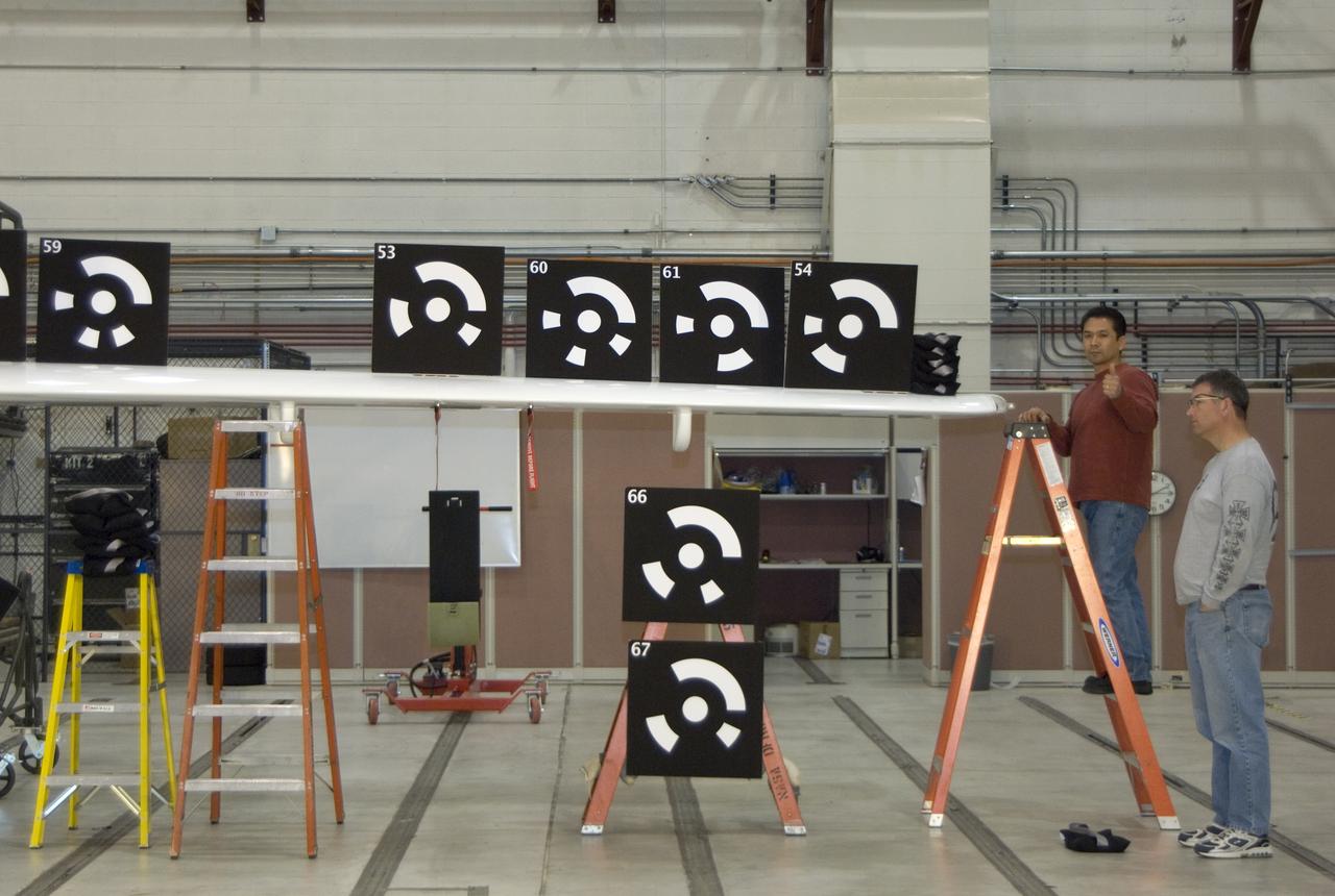
Ikhana fiber optic wing shape sensor team: clockwise from left, Anthony "Nino" Piazza, Allen Parker, William Ko and Lance Richards. The sensors, located along a fiber the thickness of a human hair, aren't visible in the center of the Ikhana aircraft's left wing. NASA Dryden Flight Research Center is evaluating an advanced fiber optic-based sensing technology installed on the wings of NASA's Ikhana aircraft. The fiber optic system measures and displays the shape of the aircraft's wings in flight. There are other potential safety applications for the technology, such as vehicle structural health monitoring. If an aircraft structure can be monitored with sensors and a computer can manipulate flight control surfaces to compensate for stresses on the wings, structural control can be established to prevent situations that might otherwise result in a loss of control.
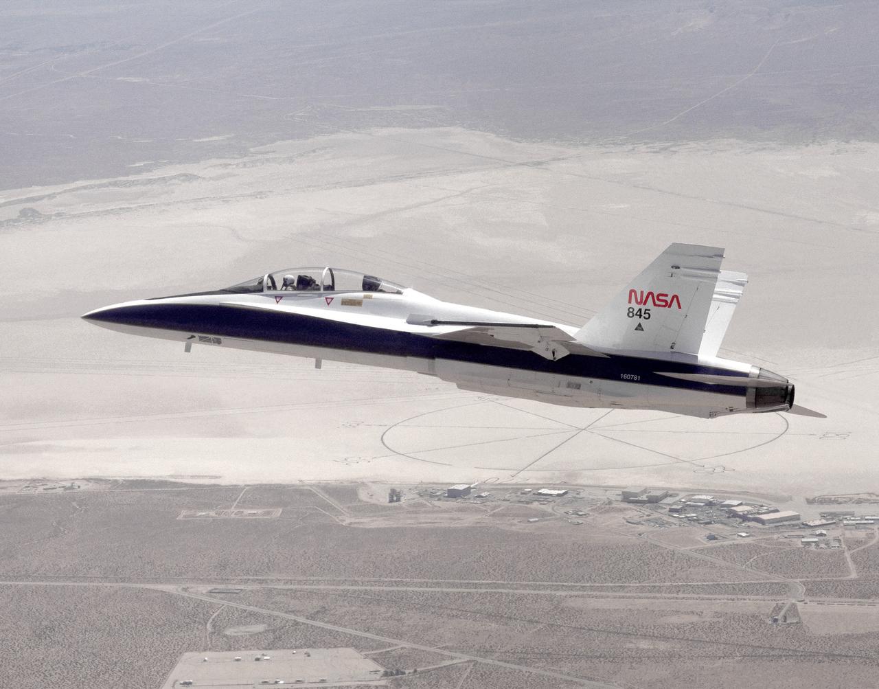
The National Aeronautics and Space Administration's Systems Research Aircraft (SRA), a highly modified F-18 jet fighter, on an early research flight over Rogers Dry Lake. The former Navy aircraft was flown by NASA's Dryden Flight Research Center at Edwards Air Force Base, California, to evaluate a number of experimental aerospace technologies in a multi-year, joint NASA/DOD/industry program. Among the more than 20 experiments flight-tested were several involving fiber optic sensor systems. Experiments developed by McDonnell-Douglas and Lockheed-Martin centered on installation and maintenace techniques for various types of fiber-optic hardware proposed for use in military and commercial aircraft, while a Parker-Hannifin experiment focused on alternative fiber-optic designs for postion measurement sensors as well as operational experience in handling optical sensor systems. Other experiments flown on this testbed aircraft included electronically-controlled control surface actuators, flush air data collection systems, "smart" skin antennae and laser-based systems. Incorporation of one or more of these technologies in future aircraft and spacecraft could result in signifigant savings in weight, maintenance and overall cost.
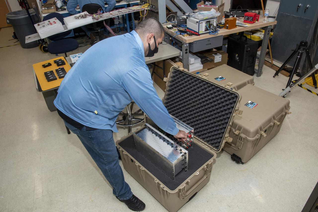
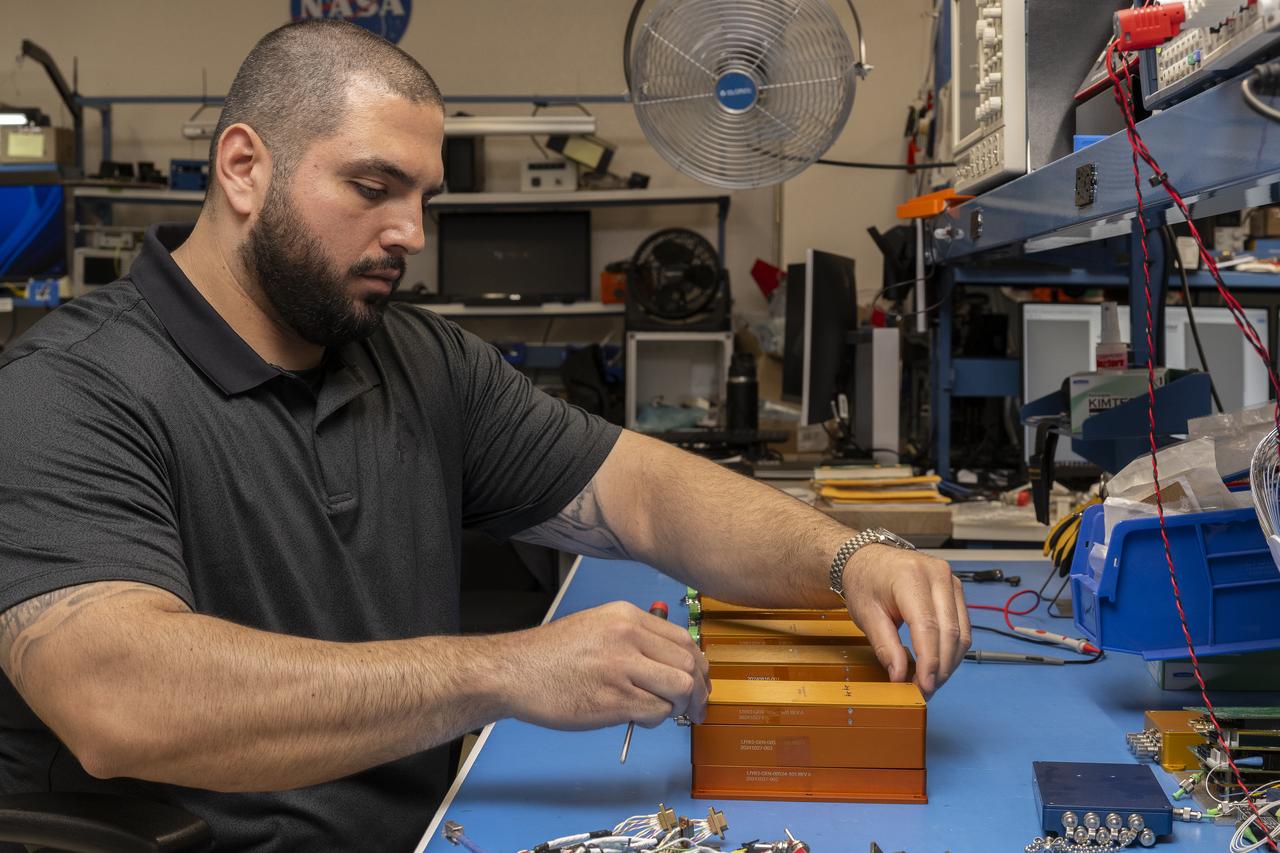
NASA research engineer Jonathan Lopez secures a Compact Fiber Optic Sensing System unit, also known as a FOSS Rocket Box, which was developed at NASA's Armstrong Flight Research Center in California. The unit is a new variant of aircraft technology that researchers have advanced to withstand the harsh environments of a rocket launch and space travel.
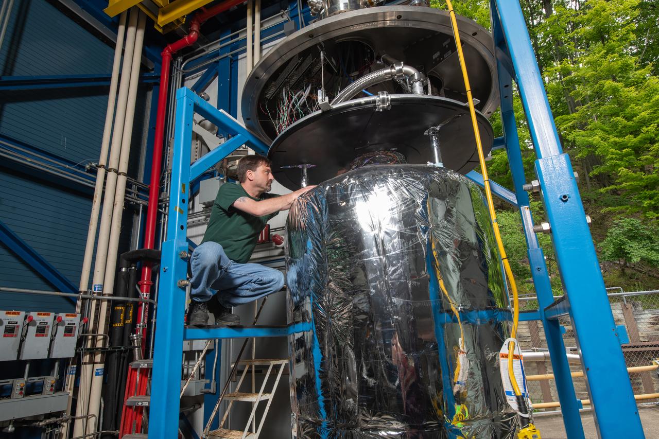
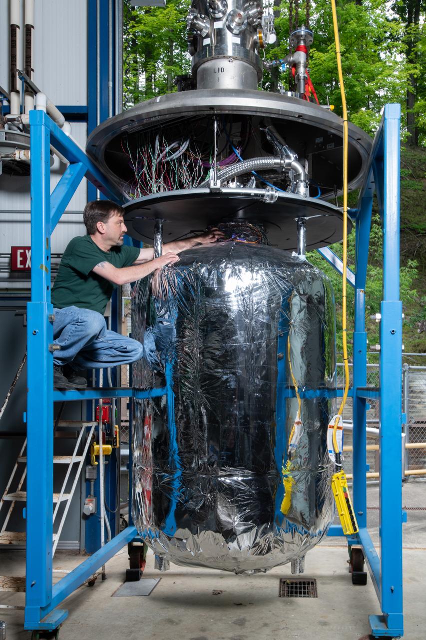
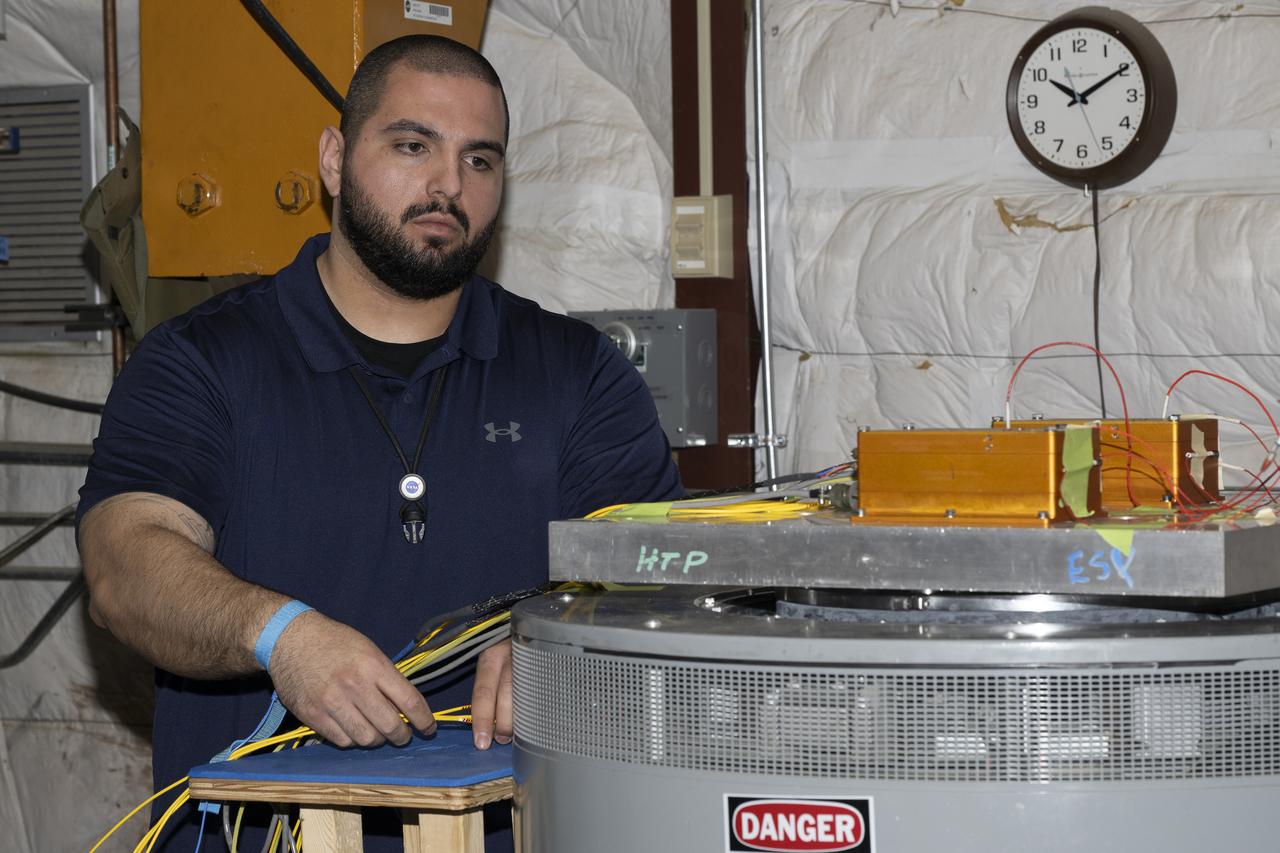
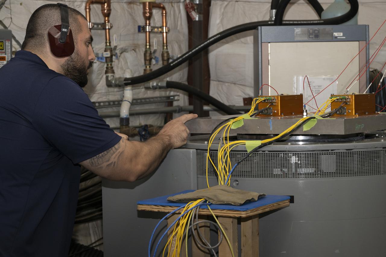
A tank is used in CryoFILL experiments to liquefy oxygen at minus 290 degrees Fahrenheit as it could be done on the Moon or Mars. The tests conducted at NASA Glenn Research Center, used Fiber Optic Sensing System (FOSS) developed by NASA Armstrong Flight Research Center, to measure oxygen temperatures inside the tank.
Jonathan Lopez works on a hypersonic Fiber Optic Sensing System at NASA’s Armstrong Flight Research Center in Edwards, California, on Feb. 13, 2025. The system measures strain and temperature, critical safety data for hypersonic vehicles that travel five time the speed of sound.
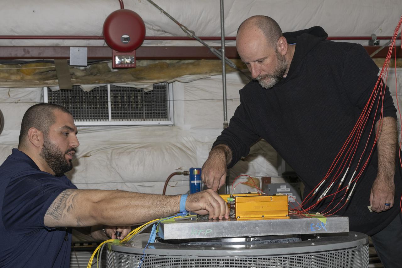
Jonathan Lopez and Nathan Rick prepare the hypersonic Fiber Optic Sensing System for vibration tests in the Environmental Laboratory at NASA’s Armstrong Flight Research Center in Edwards, California. Testing on a machine called a shaker proved that the system could withstand the severe vibration it will endure in hypersonic flight, or travel at five times the speed of sound.
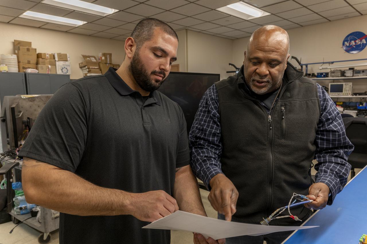
Jonathan Lopez and Allen Parker confer on the hypersonic Fiber Optic Sensor System at NASA’s Armstrong Flight Research Center in Edwards, California, on February 13, 2025. The system measures strain and temperature, critical safety data for hypersonic vehicles that travel five time the speed of sound.
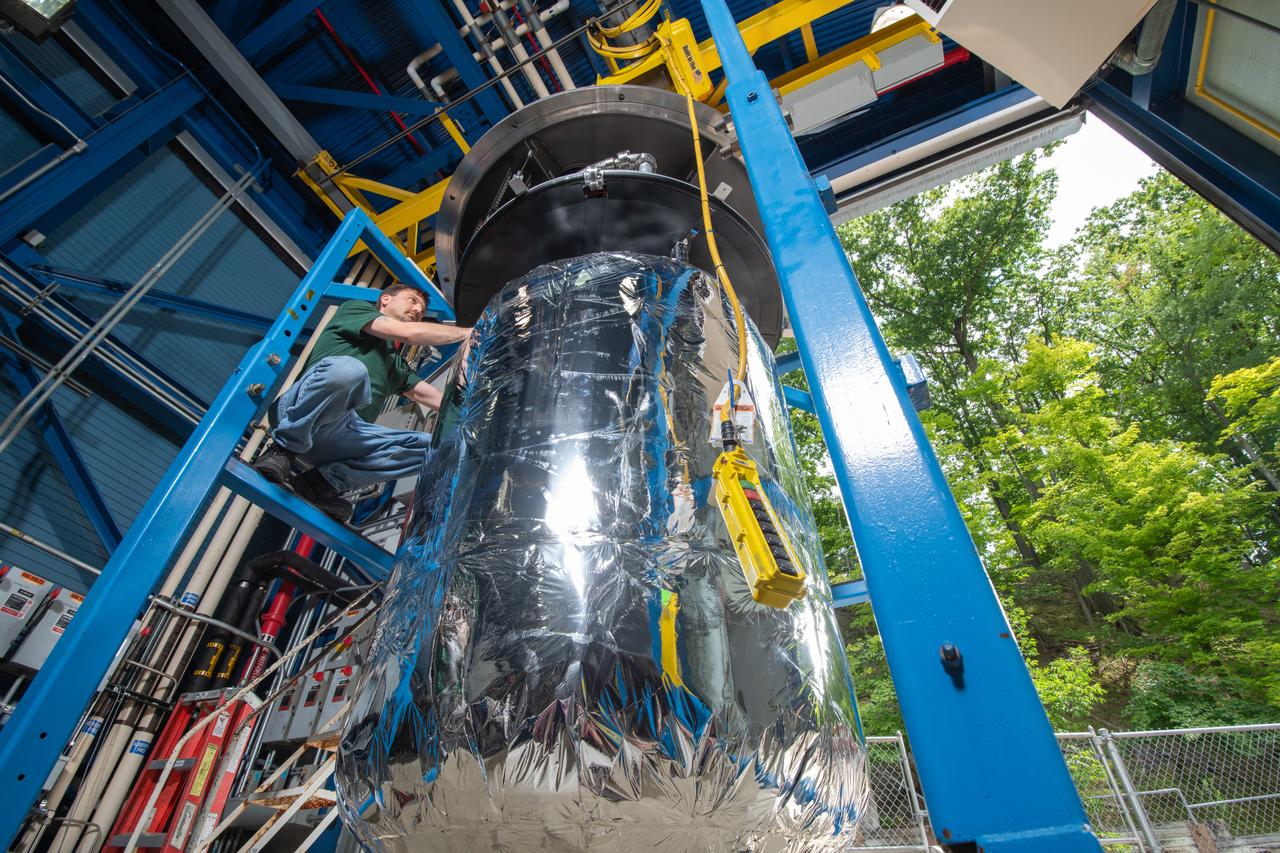
A tank is used in CryoFILL experiments to liquefy oxygen at minus 290 degrees Fahrenheit as it could be done on the Moon or Mars. The tests conducted at NASA Glenn Research Center, used Fiber Optic Sensing System (FOSS) developed by NASA Armstrong Flight Research Center, to measure oxygen temperatures inside the tank.
A tank is used in CryoFILL experiments to liquefy oxygen at minus 290 degrees Fahrenheit as it could be done on the Moon or Mars. The tests conducted at NASA Glenn Research Center, used Fiber Optic Sensing System (FOSS) developed by NASA Armstrong Flight Research Center, to measure oxygen temperatures inside the tank.
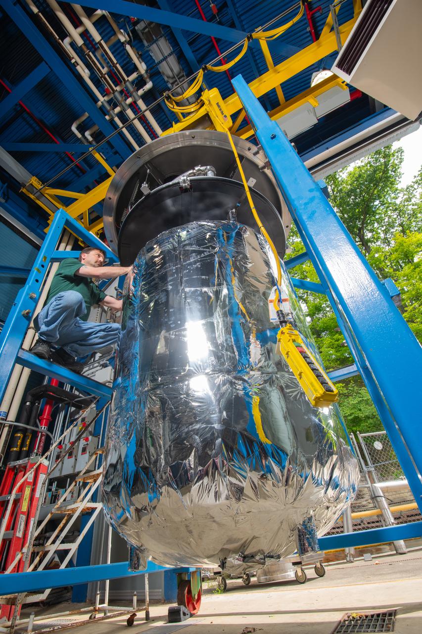
A tank is used in CryoFILL experiments to liquefy oxygen at minus 290 degrees Fahrenheit as it could be done on the Moon or Mars. The tests conducted at NASA Glenn Research Center, used Fiber Optic Sensing System (FOSS) developed by NASA Armstrong Flight Research Center, to measure oxygen temperatures inside the tank.
Jonathan Lopez prepares the hypersonic Fiber Optic Sensing System for vibration tests in the Environmental Laboratory at NASA’s Armstrong Flight Research Center in Edwards, California. Testing on a machine called a shaker proved that the system could withstand the severe vibration it will endure in hypersonic flight, or travel at five times the speed of sound.
Jonathan Lopez prepares the hypersonic Fiber Optic Sensing System for vibration tests in the Environmental Laboratory at NASA’s Armstrong Flight Research Center in Edwards, California. Testing on a machine called a shaker proved that the system could withstand the severe vibration it will endure in hypersonic flight, or travel at five times the speed of sound.
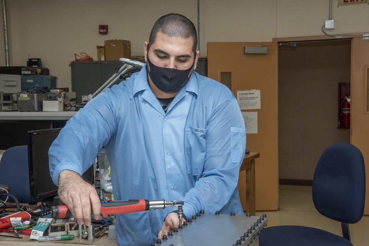
Bolts are torqued on a Compact Fiber Optic Sensing System unit, also known as a FOSS Rocket Box, which was developed at NASA's Armstrong Flight Research Center in California. NASA research engineer Jonathan Lopez works on the unit that is a new variant of aircraft technology that researchers have advanced to withstand the harsh environments of a rocket launch and space travel
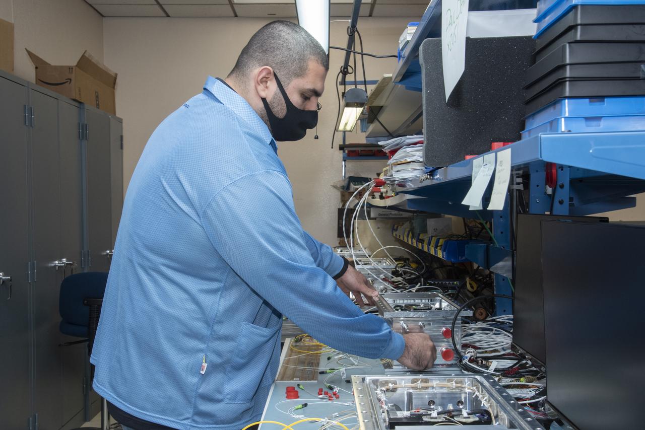
NASA research engineer Jonathan Lopez works on preparing a Compact Fiber Optic Sensing System unit, also known as a FOSS Rocket Box, which was developed at NASA's Armstrong Flight Research Center in California. The unit is a new variant of aircraft technology that researchers have advanced to withstand the harsh environments of a rocket launch and space travel.
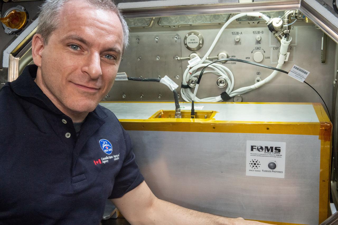
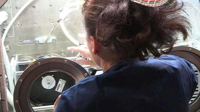
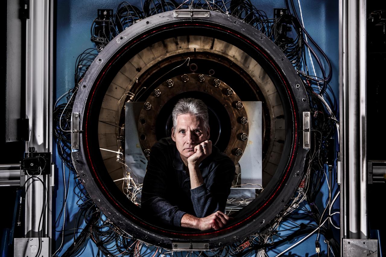
iss059e034721 (4/23/2019) --- Canadian Space Agency (CSA) astronaut David Saint-Jacques is photographed in front of the Microgravity Science Glovebox (MSG) during the installation of the Space Fibers experiment hardware into the MSG work volume. Manufacturing Fiber Optic Cable in Microgravity (Space Fibers) evaluates a method for producing fiber optic cable from a blend of zirconium, barium, lanthanum, sodium and aluminum, called ZBLAN, in space. ZBLAN produces glass one hundred times more transparent than silica-based glass, exceptional for fiber optics. Microgravity suppresses two mechanisms that commonly degrade fiber, and previous studies showed improved properties in fiber drawn in microgravity compared to that fabricated on the ground.
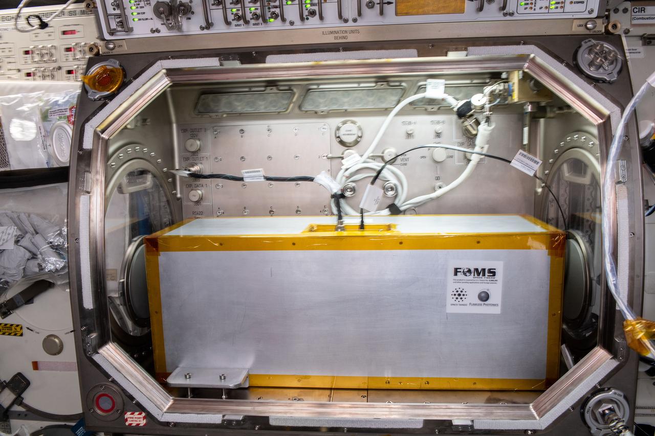
iss059e034705 (4/23/2019) --- A view taken during the installation of the Space Fibers experiment hardware into the Microgravity Science Glovebox (MSG) in the Destiny module aboard the International Space Station (ISS). Manufacturing Fiber Optic Cable in Microgravity (Space Fibers) evaluates a method for producing fiber optic cable from a blend of zirconium, barium, lanthanum, sodium and aluminum, called ZBLAN, in space. ZBLAN produces glass one hundred times more transparent than silica-based glass, exceptional for fiber optics. Microgravity suppresses two mechanisms that commonly degrade fiber, and previous studies showed improved properties in fiber drawn in microgravity compared to that fabricated on the ground.
jsc2021e044608 (9/23/2021) --- A microscopic image of a section of ZBLAN optical fiber produced by the second iteration of Fiber Optic Production (FOP1.5) aboard the International Space station (ISS). Image courtesy of Mercury Systems.
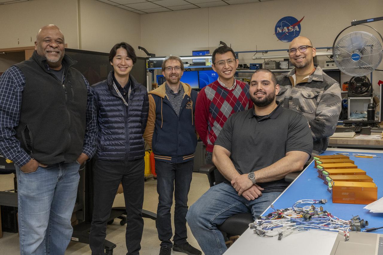
Allen Parker, Mark Hagiwara, Paul Bean, Patrick Chan, Jonathan Lopez (seated), and Frank Pena comprise the Fiber Optic Sensing System team at NASA’s Armstrong Flight Research Center, in Edwards, California. The systems on the table measure strain and temperature, critical safety data for hypersonic vehicles that travel five time the speed of sound.
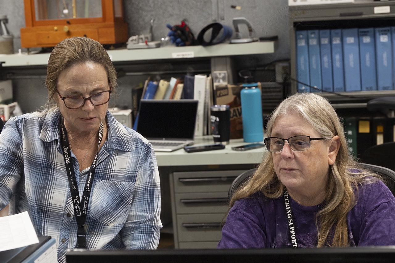
From left, April Torres and Karen Estes watch incoming data from vibration tests on the hypersonic Fiber Optic Sensing System at NASA’s Armstrong Flight Research Center in Edwards California. Testing on a machine called a shaker proved that the system could withstand the severe vibration it will endure in hypersonic flight, or travel at five times the speed of sound.
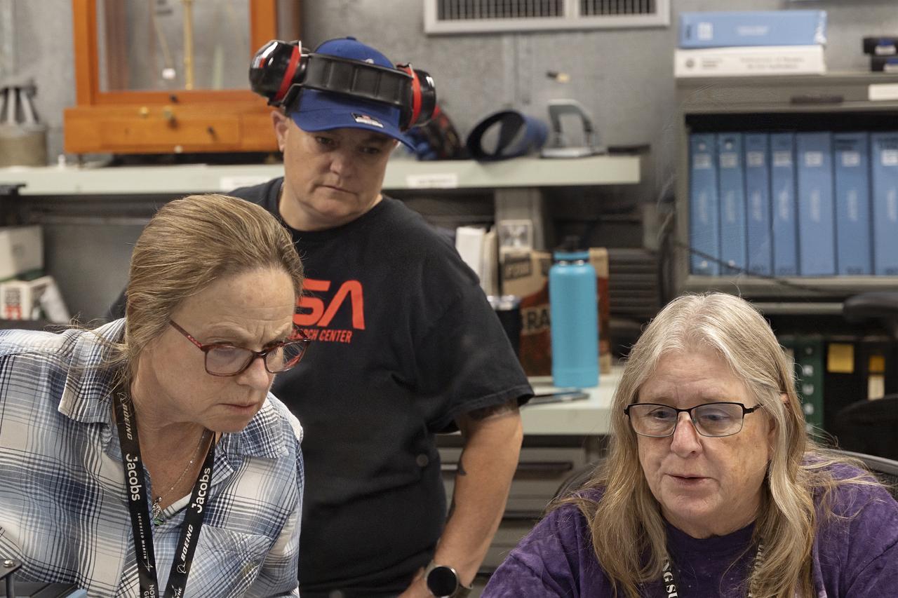
April Torres, from left, Cryss Punteney, and Karen Estes watch as data flows from the hypersonic Fiber Optic Sensing System at NASA’s Armstrong Flight Research Center in Edwards, California. Testing on a machine called a shaker proved that the system could withstand the severe vibration it will endure in hypersonic flight, or travel at five times the speed of sound.
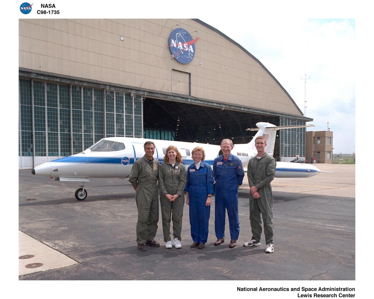
FIBER OPTIC TEMPERATURE TEST PROGRAM ON LEAR JET
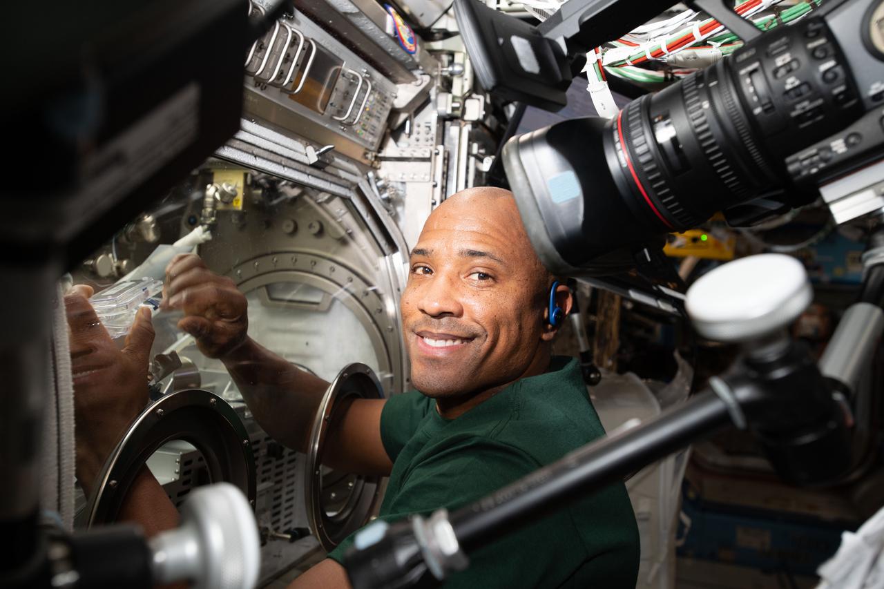
NASA astronaut and Expedition 64 Flight Engineer Victor Glover performs a sample exchange in the Microgravity Science Glovebox (MSG) as part of the Fiber Optic Production (FOP) experiment. FOP produces fiber optic cable in microgravity from a blend of elements called ZBLAN. Previous research suggests optical fibers produced in microgravity should exhibit superior qualities to those produced on Earth.
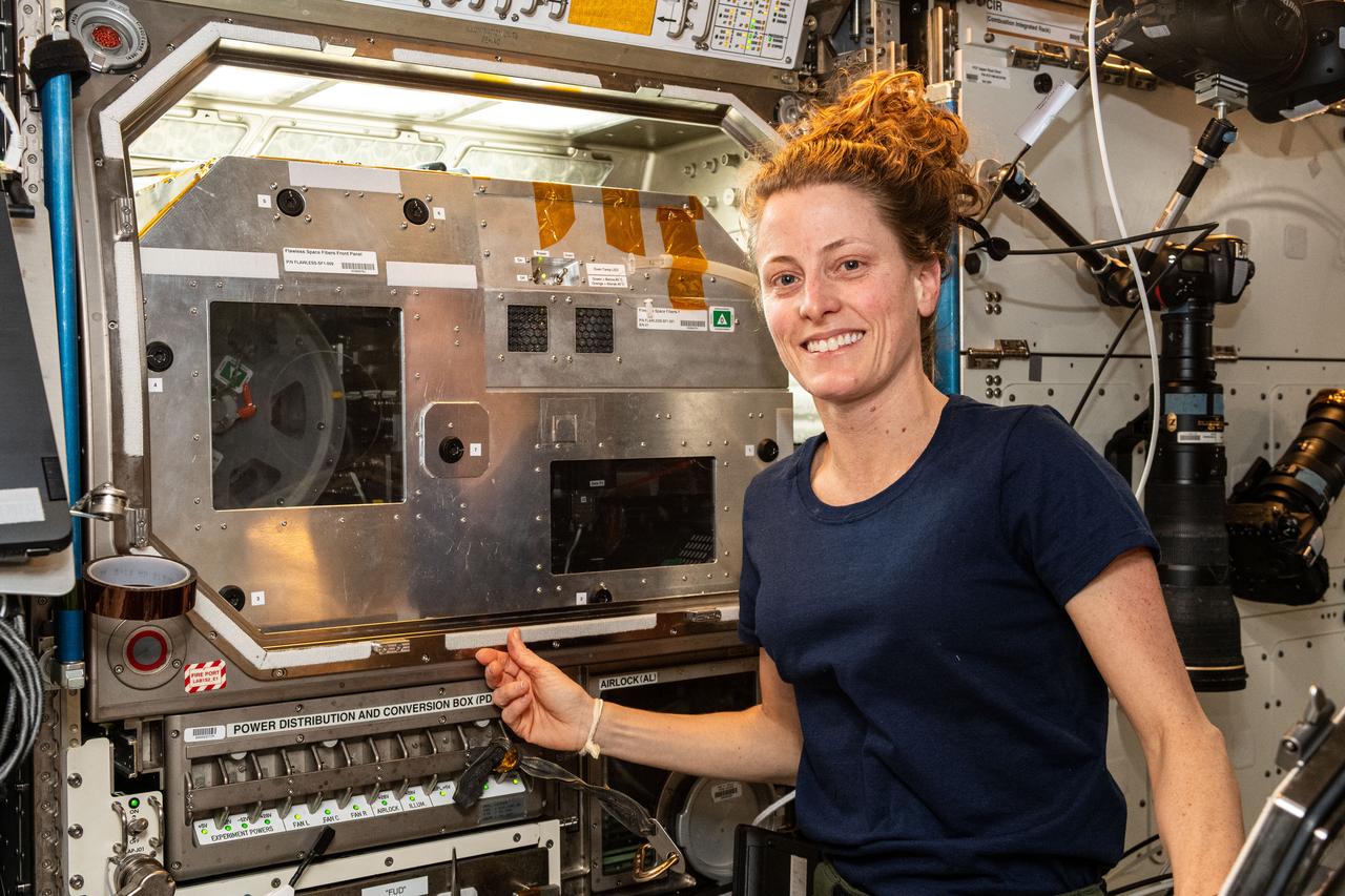
ISS070E110532 - NASA astronaut Loral O'Hara poses in front of the Destiny laboratory’s Microgravity Science Glovebox (MSG) during Flawless Space Fibers operations. Production of Flawless Space Fiber (Flawless Space Fibers-1) tests new hardware and processes for producing high-quality optical fibers in space.
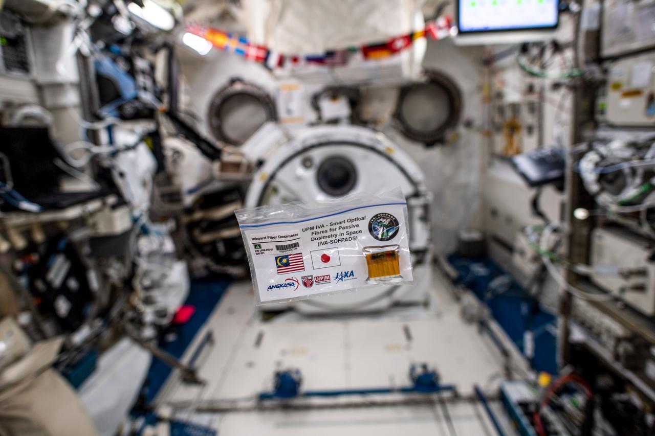
jsc2020e040981 (9/4/2019) --- I view of the IVA-SOFPADS floating inside the Kibo module aboard the International Space Station (ISS). The objective of the Smart Optical Fibers for Passive Dosimetry in Space (SOFPADS), or Fiber Dosimeter, investigation is to evaluate the use of fabricated optical fibers as space radiation passive dosimeters to monitor the radiation environment inside and outside of the International Space Station (ISS). Image Credit: NASA/JAXA
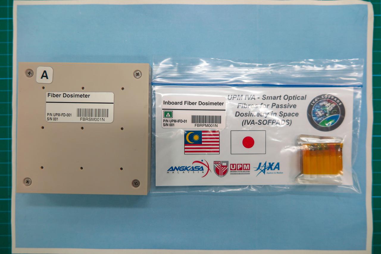
jsc2020e040980 (11/2/2018) --- Image of EVA-SOFPADS (Left) and IVA-SOFPADS (Right) taken at JAXA during samples handover. The objective of the Smart Optical Fibers for Passive Dosimetry in Space (SOFPADS), or Fiber Dosimeter, investigation is to evaluate the use of fabricated optical fibers as space radiation passive dosimeters to monitor the radiation environment inside and outside of the International Space Station (ISS). Image Credit: JAXA
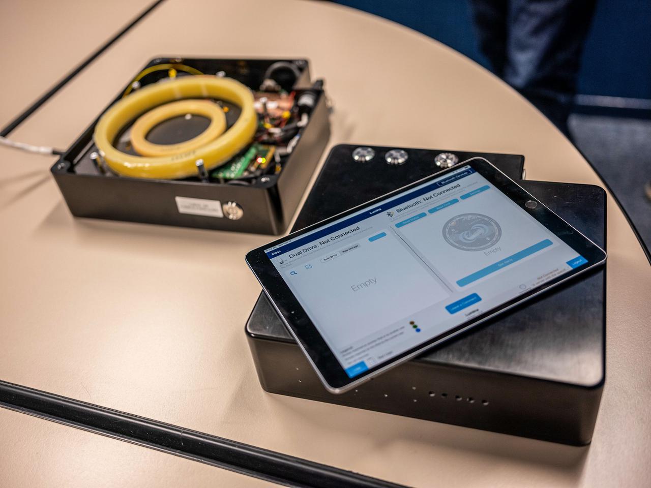
jsc2021e029984 (3/18/20210 --- A preflight view of the Lumina imvestigation. Fiber-optic Active Dosimeter (Lumina) is an active fiber dosimeter that monitors, in real-time, the received radiation dose by exploiting the capacity of optical fibers to darken when exposed to radiation. The dosimeter provides reliable dose measurements in complex environments such as the ones associated with electrons, protons, gamma-ray or X-ray photons or neutrons.
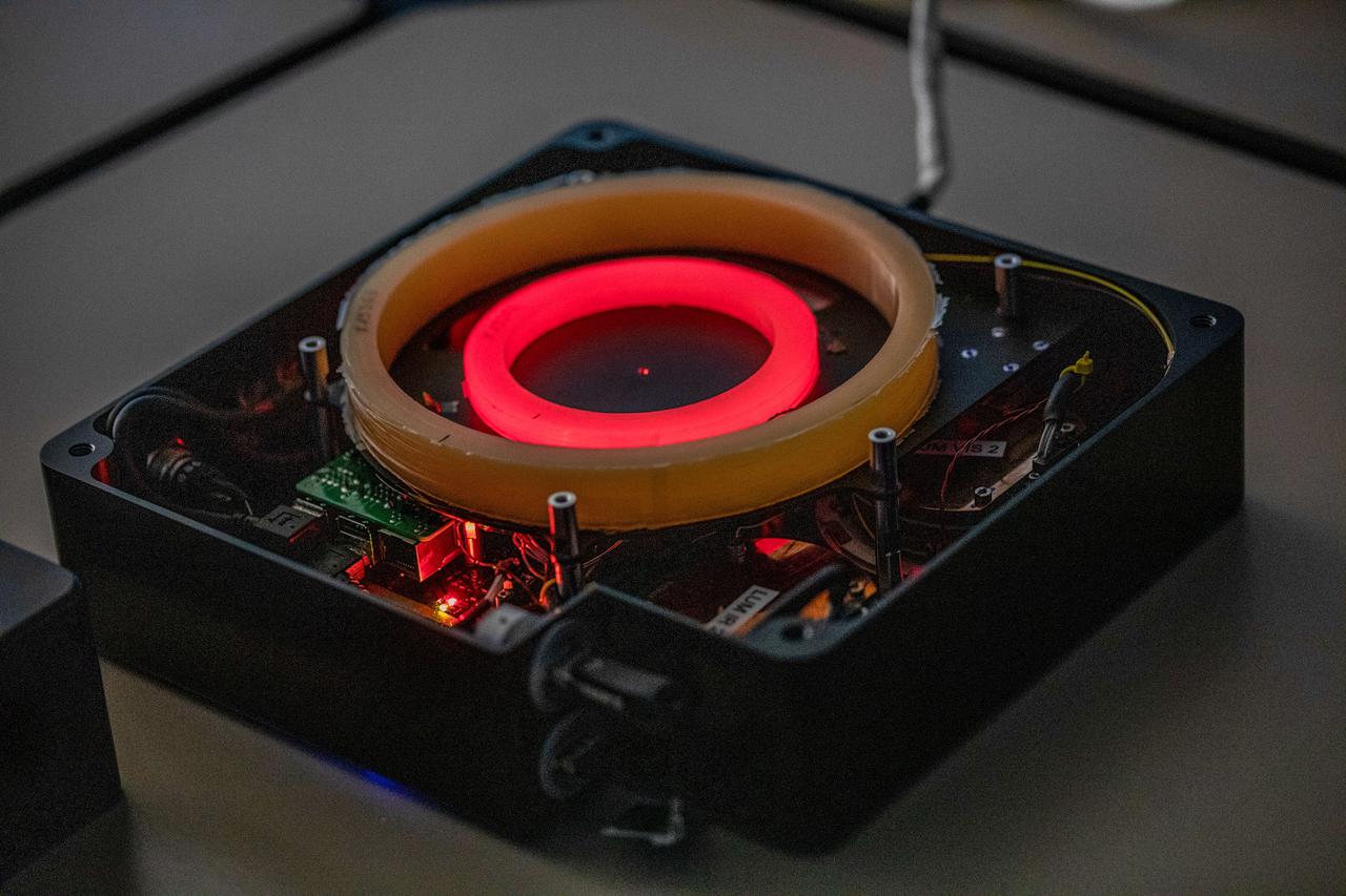
jsc2021e029985 (3/18/20210 --- A preflight view of the Lumina imvestigation. Fiber-optic Active Dosimeter (Lumina) is an active fiber dosimeter that monitors, in real-time, the received radiation dose by exploiting the capacity of optical fibers to darken when exposed to radiation. The dosimeter provides reliable dose measurements in complex environments such as the ones associated with electrons, protons, gamma-ray or X-ray photons or neutrons.
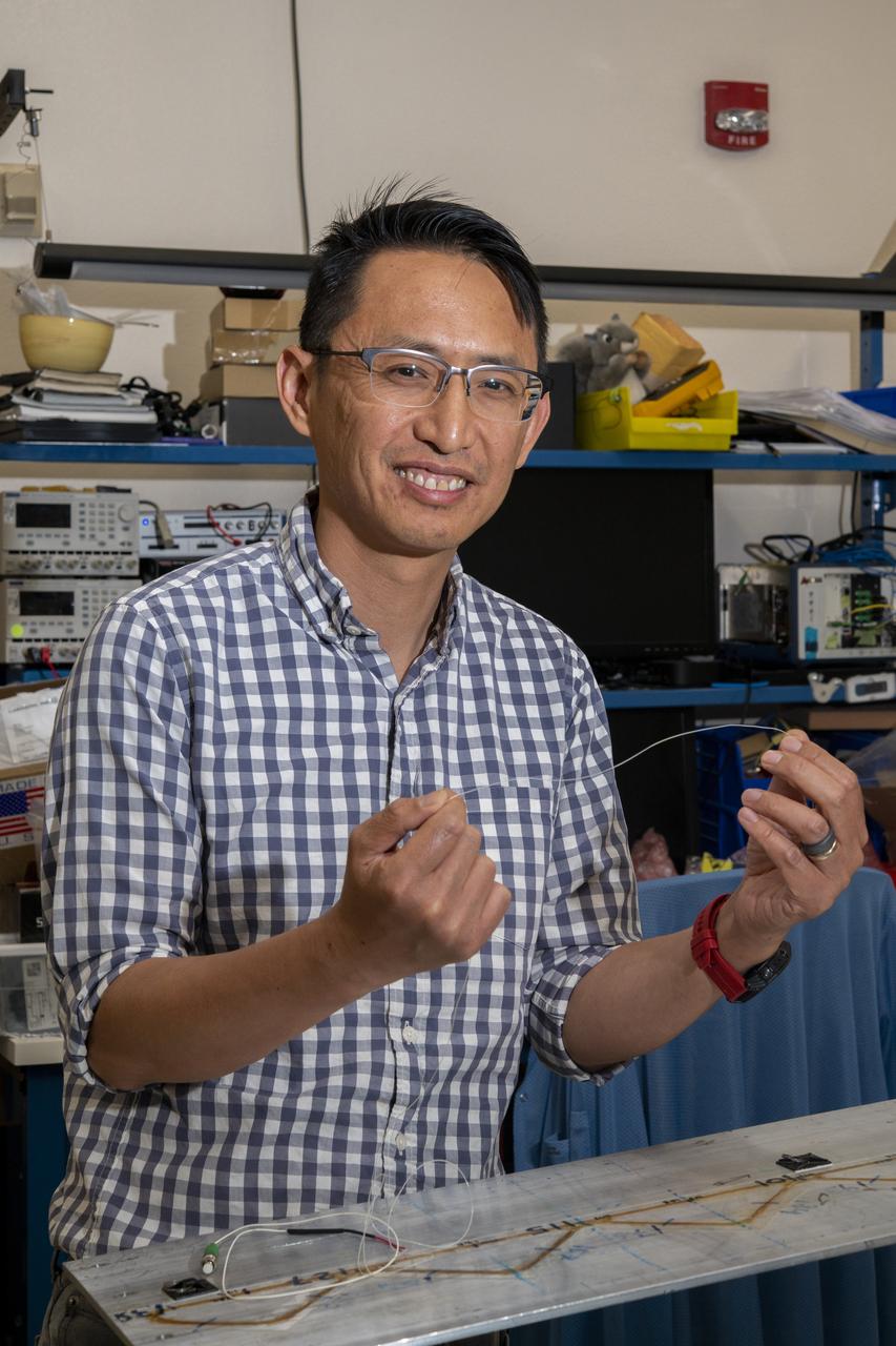
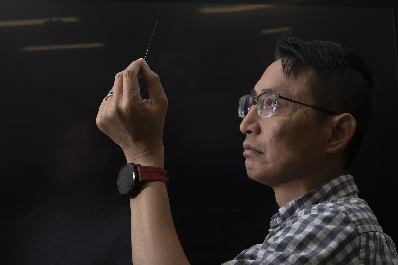
NASA’s Armstrong Flight Research Center’s FOSS, Fiber Optic Sensing System, recently supported tests of a system designed to turn oxygen into liquid oxygen, a component of rocket fuel. Patrick Chan, electronics engineer, and NASA Armstrong’s FOSS portfolio project manager, shows fiber like that used in the testing.
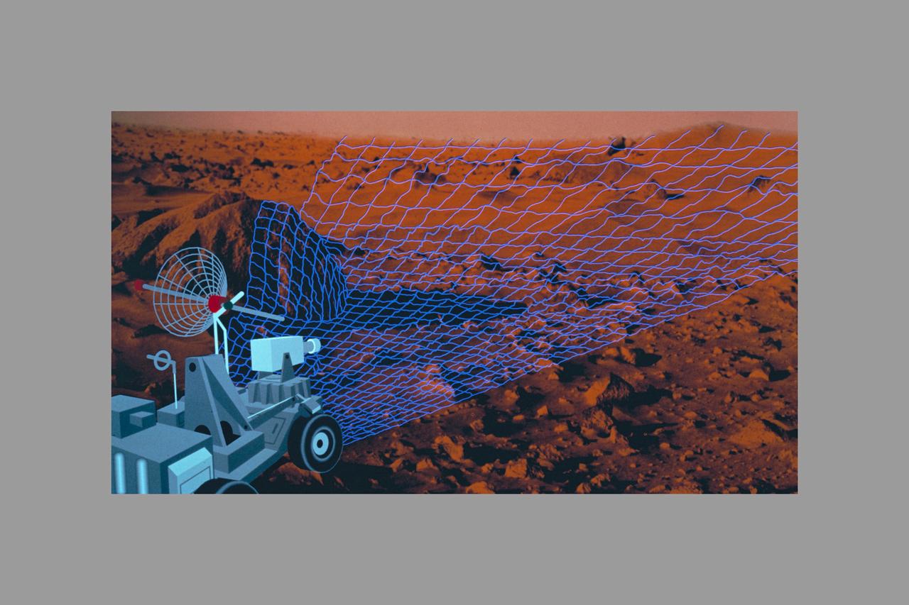
Autonomous Perception Vision project - Intelligent Systems - Machine Vision, Fusing Photonics and A.I. - Fiber-Optic Probe for Laser Velocimetry (Mars)
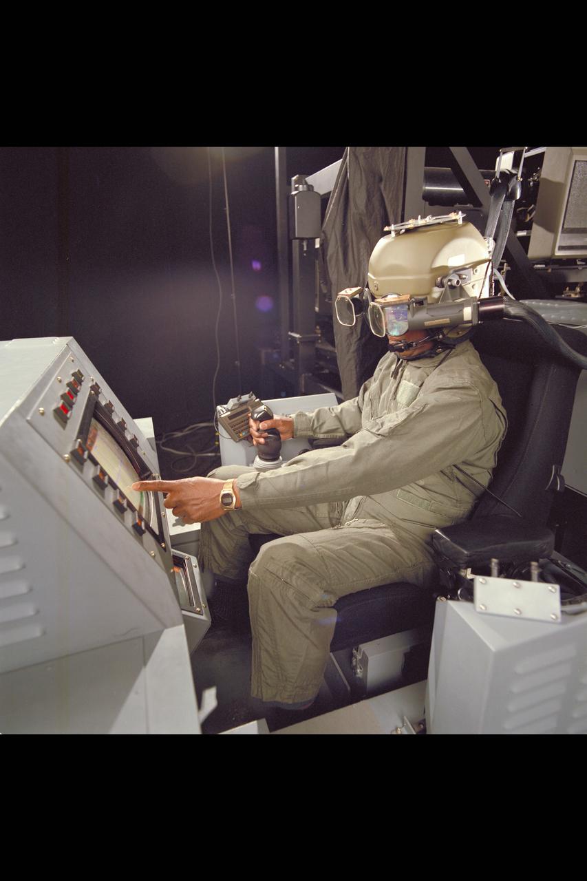
Crew Station Research and Developement Facility (CSRDF) A NASA Army simulator to design and evaluate advanced rotorcraft showing fiber optic helmet & workstation
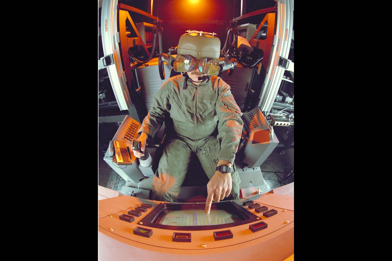
Crew Station Research and Developement Facility (CSRDF) A NASA Army simulator to design and evaluate advanced rotorcraft showing fiber optic helmet & workstation
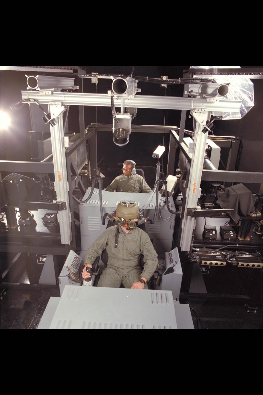
Crew Station Research and Developement Facility (CSRDF) A NASA Army simulator to design and evaluate advanced rotorcraft showing fiber optic helmet & workstation
Patrick Chan, electronics engineer, and NASA Armstrong’s FOSS portfolio project manager, closely examines an optic fiber inside of a protective sleeve. Armstrong’s Fiber Optic Sensing System recently supported tests in which oxygen was turned into liquid oxygen at minus 297 degrees Fahrenheit. Testing was aimed at developing technologies could allow future astronauts to manufacture rocket fuel on the Moon.

iss064e011648 (Dec. 10, 2020) --- NASA astronaut and Expedition 64 Flight Engineer Michael Hopkins conducts research activities inside the Microgravity Science Glovebox for the Fiber Optic Production experiment. The space manufacturing investigation creates optical fibers in microgravity with high commercial value that should exhibit far superior qualities to those produced on Earth.
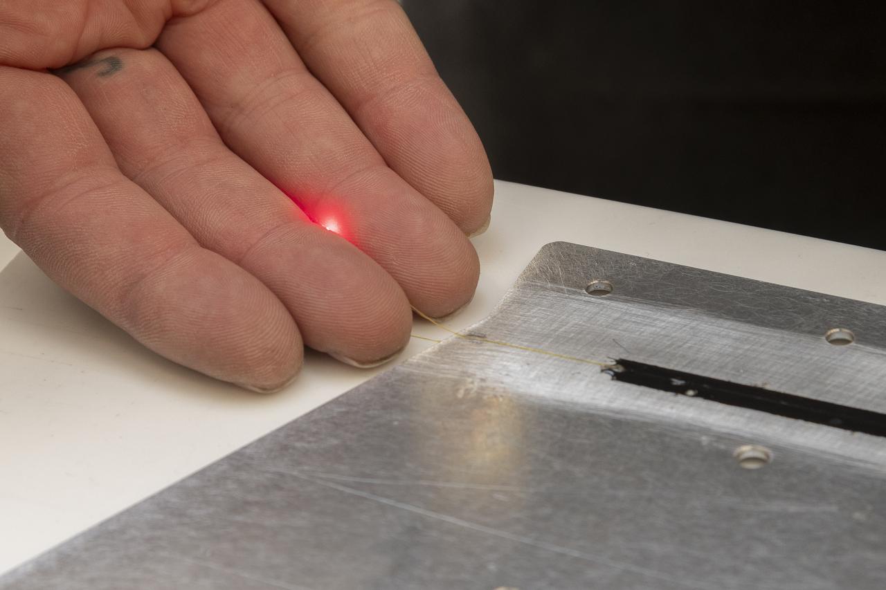
A red light confirms that the fiber of the Fiber Optic Sensing System installed on the Mock Truss-Braced Wing 10-foot model works as intended at NASA’s Armstrong Flight Research Center in Edwards, California. The fiber, which is about the thickness of a human hair, is part of a system that can provide strain information researchers can use to determine the model’s durability.
jsc2021e012558 (12/2021) --- NASA astronaut Shannon Walker, handling the fiber produced by the second iteration of FOP hardware (FOP1.5) during the ISS demo in December 2020. Image courtesy of Physical Optics Corporation.
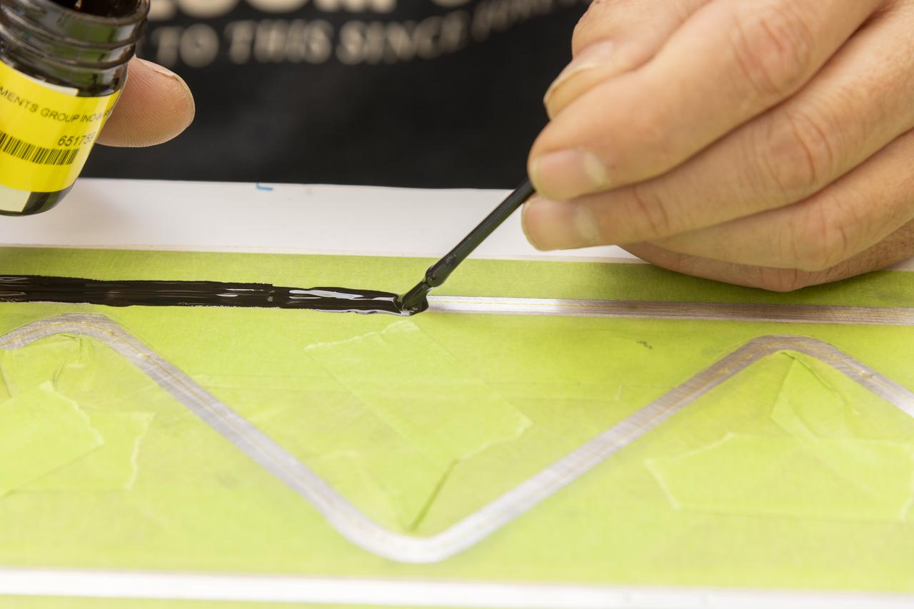
An epoxy is applied to adhere the fiber optic sensor installation on the Mock Truss-Braced Wing 10-foot model at NASA’s Armstrong Flight Research Center in Edwards, California.
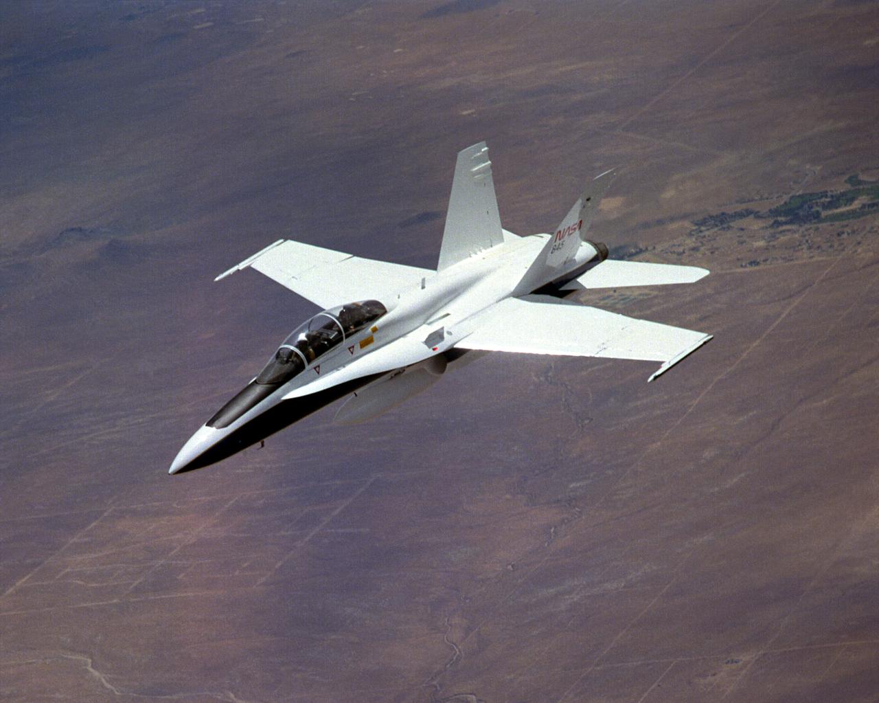
The National Aeronautics and Space Administration's Systems Research Aircraft (SRA), a highly modified F-18 jet fighter, during a research flight. The former Navy aircraft was flown by NASA's Dryden Flight Research Center at Edwards Air Force Base, California, to evaluate a number of experimental aerospace technologies in a multi-year, joint NASA/DOD/industry program. Among the more than 20 experiments flight-tested were several involving fiber optic sensor systems. Experiments developed by McDonnell-Douglas and Lockheed-Martin centered on installation and maintenace techniques for various types of fiber-optic hardware proposed for use in military and commercial aircraft, while a Parker-Hannifin experiment focused in alternative fiber-optic designs for position measurement sensors as well as operational experience in handling optical sensor systems. Other experiments flown on this testbed aircraft included electronically-controlled control surface actuators, flush air data collection systems, "smart" skin antennae and laser-based systems. Incorporation of one or more of these technologies in future aircraft and spacecraft could result in signifigant savings in weight, maintenance and overall cost.
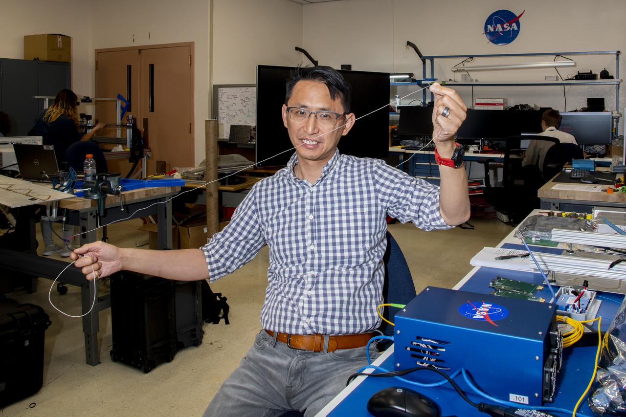
Patrick Chan, electronics engineer, and NASA Armstrong Flight Research Center’s FOSS portfolio project manager, shows a fiber used in a temperature sensing system. Armstrong’s Fiber Optic Sensing System was used to measure temperatures during tests aimed at turning oxygen into liquid oxygen. Testing was conducted at NASA’s Glenn Research Center in Cleveland, Ohio.
Steven Grantham (NIST) and John Woodward (NIST) contemplate cable management for air-LUSI’s Irradiance Instrument Subsystem telescope at NASA’s Armstrong Flight Research Center in Palmdale, CA. It is critical that the delicate fiber optic cables move smoothly with the telescope.
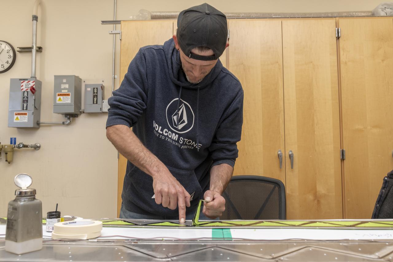
Engineering technician Jeff Howell removes tape from the Mock Truss-Braced Wing 10-foot model at NASA’s Armstrong Flight Research Center in Edwards, California. The tape was used to limit the amount of epoxy on the model wing during the process to secure the fiber optic strain sensors to the wing.
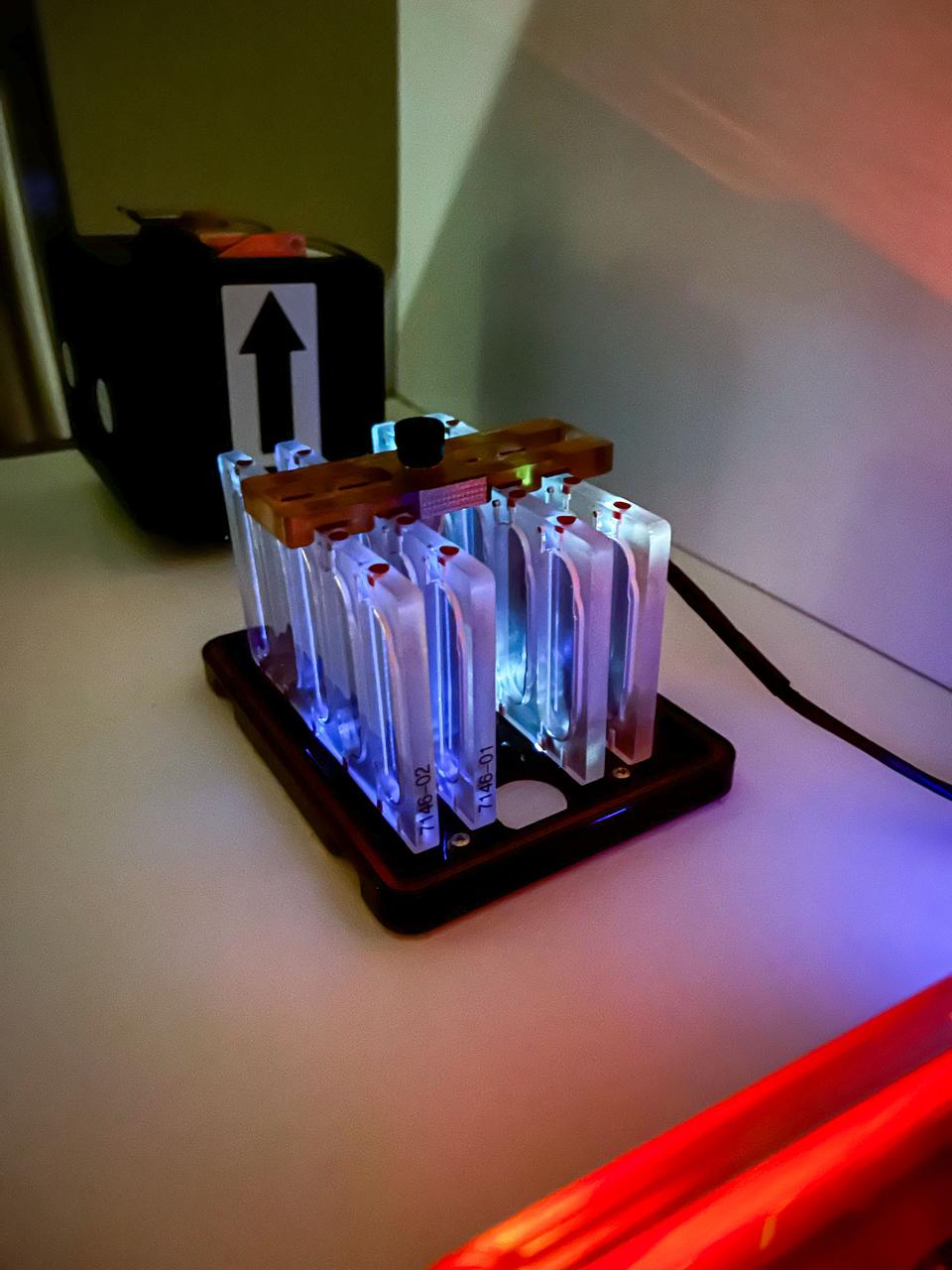
jsc2025e067422 97/9/2025) --- Agar plates for the GULBI investigation. This research uses special optical fibers to deliver ultraviolet (UV) light to inhibit the formation of microbial communities called biofilms and examine how microgravity affects the results. Credit: Arizona State University
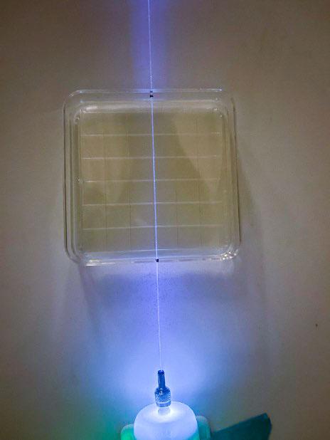
jsc2025e067423 (8/5/20250 --- Germicidal UV light is emitted by an optical fiber running through the center of an agar plate. Researchers are testing whether microgravity changes the ability of the light to prevent growth of microbial communities known as biofilms. Credit: Arizona State University
The X-37 advanced technology demonstrator flaperon unit was one of the first ever thermal and mechanical qualification tests of a carbon-carbon control surface designed for space flight. The test also featured extensive use of high-temperature fiber optic strain sensors. Peak temperatures reached 2,500 degrees Fahrenheit.

Engineering technician Jeff Howell mounts conventional strain gauges to the Mock Truss-Braced Wing 10-foot model at NASA’s Armstrong Flight Research Center in Edwards, California. The conventional system data will be compared the Fiber Optic Sensing System developed at the center on the same wing to see how well the testing methods match.
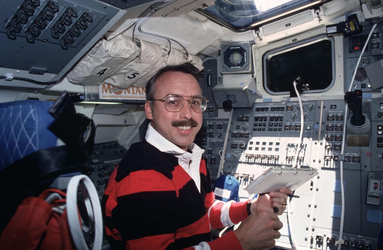
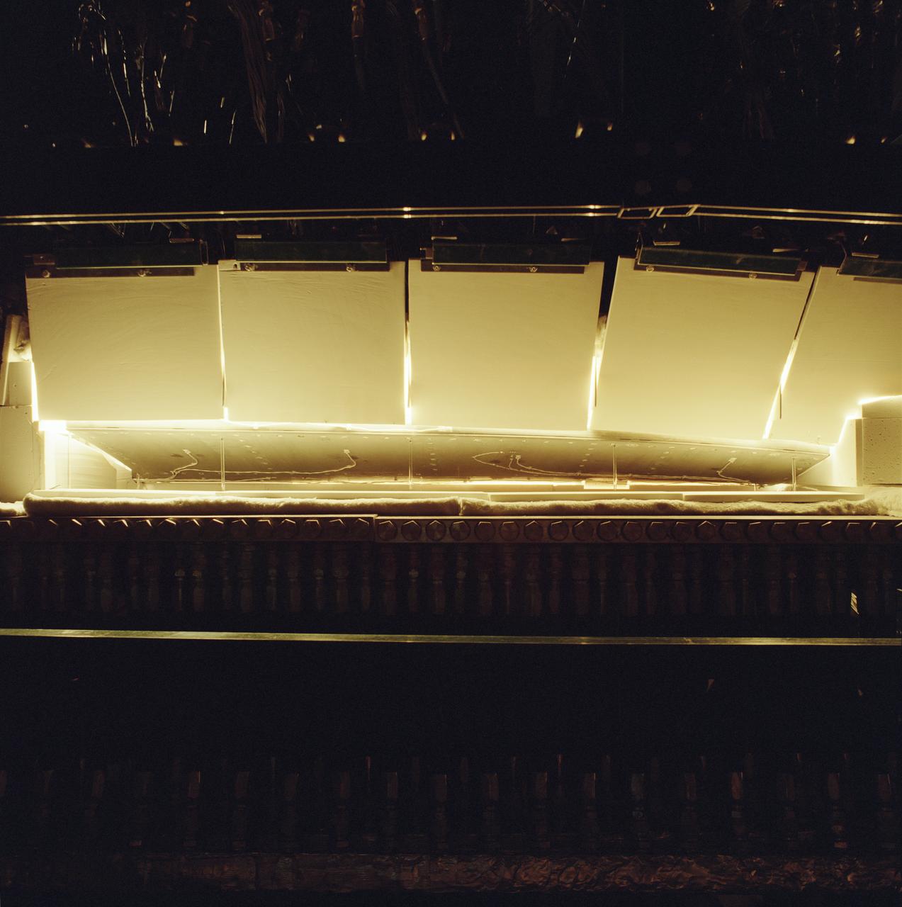
STS043-04-038 (2-11 Aug 1991) --- Astronaut James C. Adamson, STS-43 mission specialist, checks on an experiment on Atlantis? flight deck. Part of the experiment, Optical Communications Through the Shuttle Window (OCTW), can be seen mounted in upper right. The OCTW system consists of two modules, one inside the orbiter crew cabin (as pictured here) and one in the payload bay. The crew compartment version houses an optoelectronic transmitter/receiver pair for video and digital subsystems, test circuitry and interface circuitry. The payload bay module serves as a repeater station. During operation a signal is transmitted through the shuttle window to a bundle of optical fiber cables mounted in the payload bay near an aft window. The cables carry optical signals from the crew compartment equipment to the OCTW payload bay module. The signals are returned via optical fiber cable to the aft flight deck window, retransmitted through the window, and received by the crew compartment equipment.
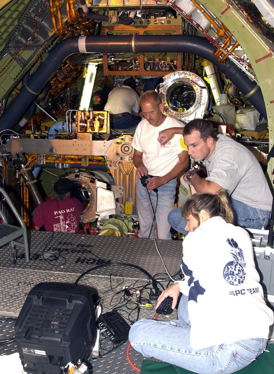
KENNEDY SPACE CENTER, FLA. -- With the engines removed from Endeavour, the inside of Endeavour is exposed. At left center, Scott Minnick, with United Space Alliance, operates a fiber-optic camera inside the flow line. Other USA team members, right, watching the progress on a screen in front, are Gerry Kathka (with controls), Mike Fore and Peggy Ritchie. The inspection is the result of small cracks being discovered on the LH2 Main Propulsion System (MPS) flow liners in other orbiters. Endeavour is next scheduled to fly on mission STS-113.
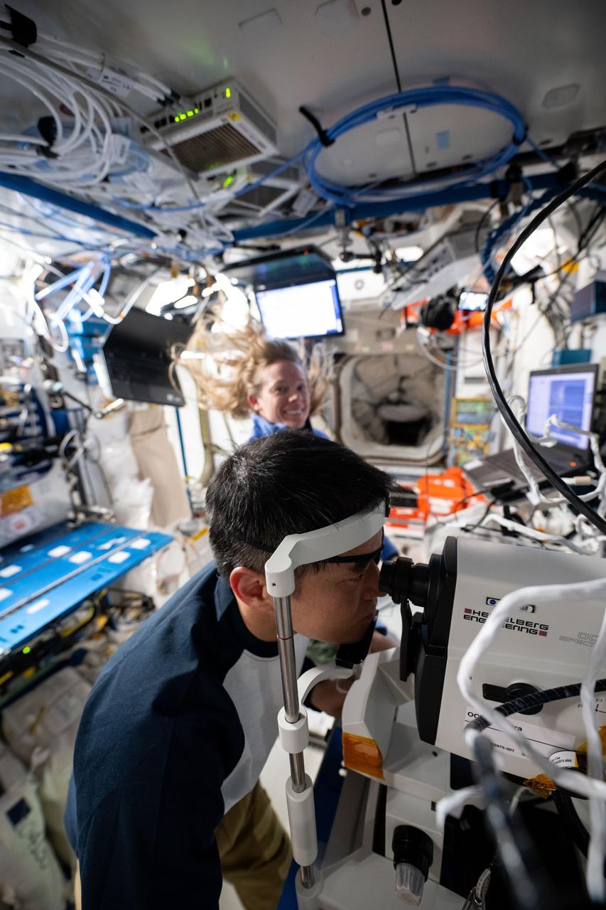
iss073e0175522 (6/9/2025) --- JAXA (Japan Aerospace Exploration Agency) astronaut Takuya Onishi, assisted by NASA astronaut Nichole Ayers, conducts an eye exam on the International Space Station using optical coherence tomography. This technology uses reflected light to produce 3D images of the retina, nerve fibers, and other eye structures and layers. Spaceflight can cause changes to eye structure and vision, so scientists monitor the eye health of crew members throughout their missions.
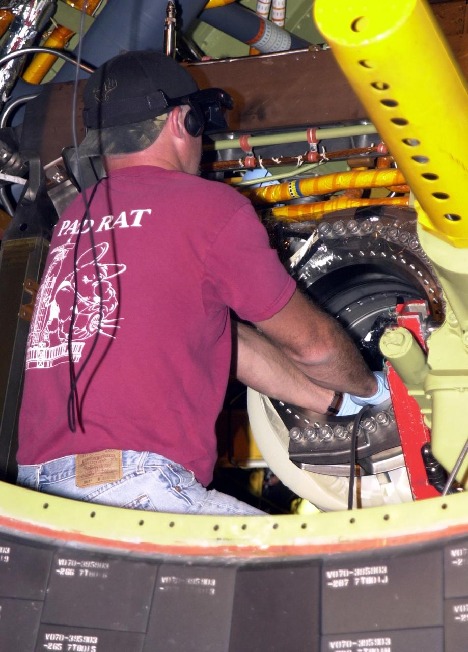
KENNEDY SPACE CENTER, FLA. -- Scott Minnick, with United Space Alliance, places a fiber-optic camera inside the flow line on Endeavour. Minnick wears a special viewing apparatus that sees where the camera is going. The inspection is the result of small cracks being discovered on the LH2 Main Propulsion System (MPS) flow liners in other orbiters. Endeavour is next scheduled to fly on mission STS-113.
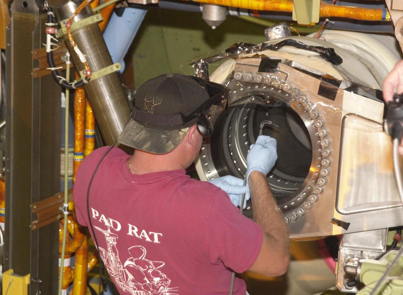
KENNEDY SPACE CENTER, FLA. -- Scott Minnick, with United Space Alliance, places a fiber-optic camera inside the flow line on Endeavour. Minnick wears a special viewing apparatus that sees where the camera is going. The inspection is the result of small cracks being discovered on the LH2 Main Propulsion System (MPS) flow liners in other orbiters. Endeavour is next scheduled to fly on mission STS-113.
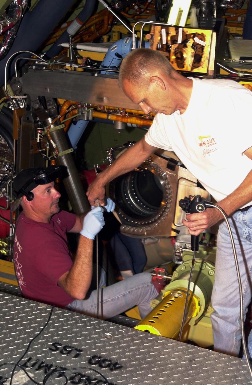
KENNEDY SPACE CENTER, FLA. -- With the engines removed from Endeavour, the flow line can be inspected. On the right, Gerry Kathka, with United Space Alliance, hands part of a fiber-optic camera system to Scott Minnick, left. Minnick wears a special viewing apparatus that sees where the camera is going. The inspection is the result of small cracks being discovered on the LH2 Main Propulsion System (MPS) flow liners in other orbiters. Endeavour is next scheduled to fly on mission STS-113.

The ER-2 ground crew Wissam Habbal, left, and Dr. Kevin Turpie, airborne Lunar Spectral Irradiance (air-LUSI) principal investigator, guide delicate fiber optic and electric cabling into place while uploading the air-LUSI instrument onto the ER-2 aircraft in March 2025 at NASA’s Armstrong Flight Research Center in Edwards, California.
How do you measure a cloud? Tim Bencic does it with lasers. The NASA Glenn engineer invented a tomography system for our Propulsion Systems Lab to help understand the dangers of ice crystal icing on airplanes. Bencic’s system, affectionally called “Tim-ography” is like a CAT Scan. The laser light within its circular geometry bounces off the surface of ice particles in the cloud and fiber optic detectors map out its properties. This tool is helping NASA’s researchers make aircraft safer in challenging weather conditions.
Marshall Space Flight Center's researchers have conducted suborbital experiments with ZBLAN, an optical material capable of transmitting 100 times more signal and information than silica fibers. The next step is to process ZBLAN in a microgravity environment to stop the formation of crystallites, small crystals caused by a chemical imbalances. Scientists want to find a way to make ZBLAN an amorphous (without an internal shape) material. Producing a material such as this will have far-reaching implications on advanced communications, medical and manufacturing technologies using lasers, and a host of other products well into the 21st century.
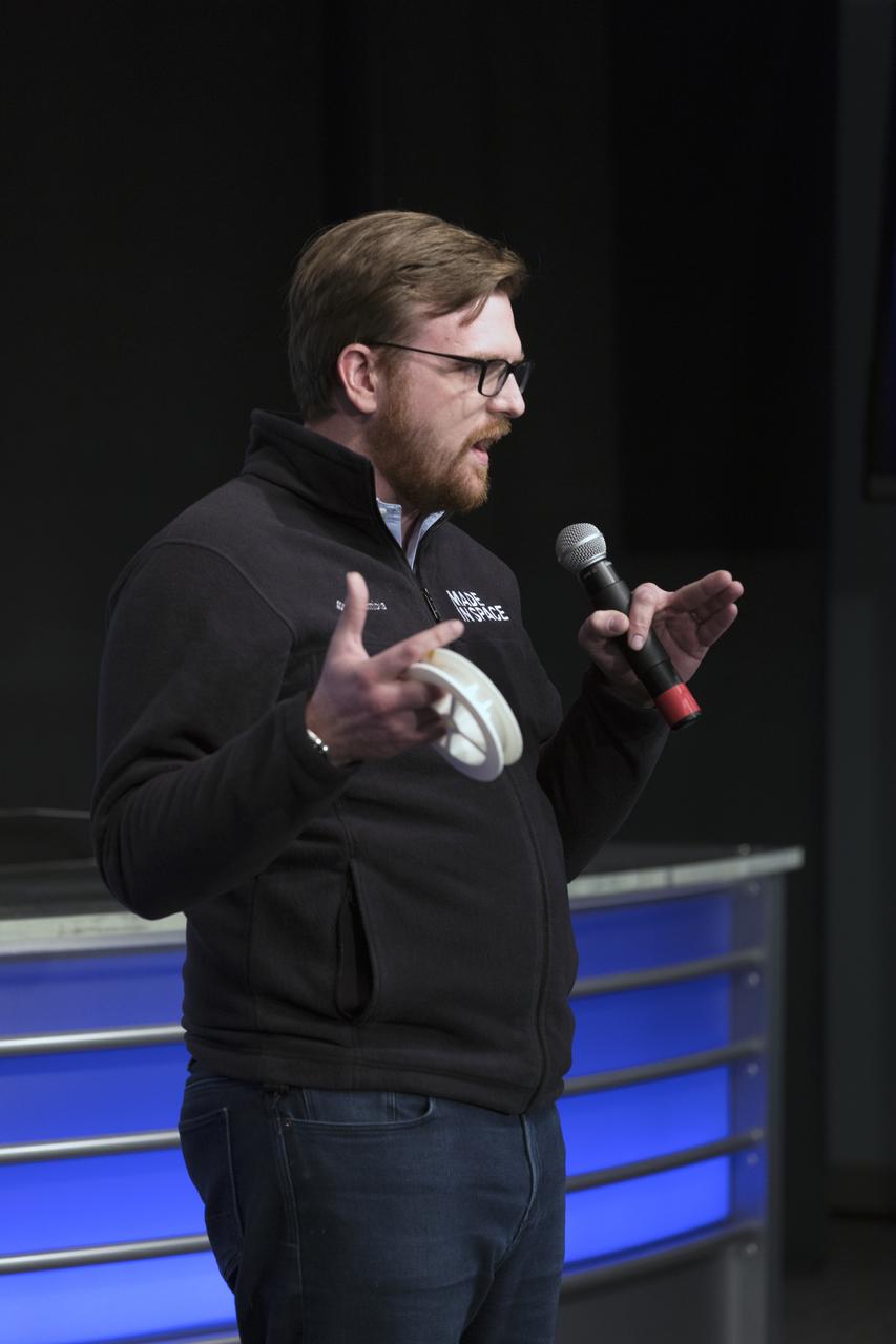
Andrew Rush, president and chief executive officer of Made in Space, discusses his company's Fiber Optics payload, with members of social media in the Kennedy Space Center’s Press Site auditorium. The briefing focused on research planned for launch to the International Space Station. The scientific materials and supplies will be aboard a Dragon spacecraft scheduled for liftoff from Cape Canaveral Air Force Station's Space Launch Complex 40 at 11:46 a.m. EST, on Dec. 12, 2017. The SpaceX Falcon 9 rocket will launch the company's 13th Commercial Resupply Services mission to the space station.
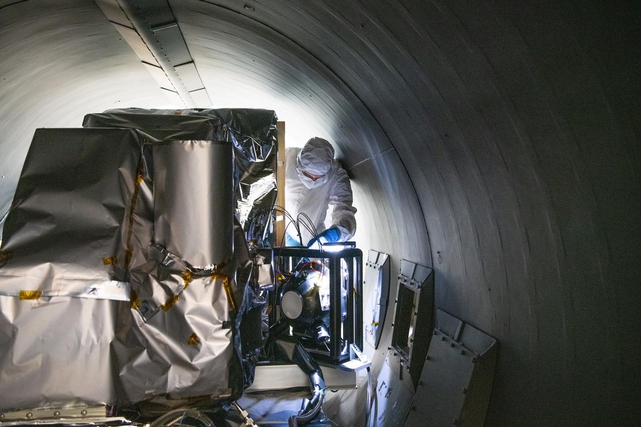
Engineer, Joe Thomes, disconnects the Multi-Lens Array fibers from the Ocean Color Instrument (OCI) in the thermal vacuum chamber after successful thermal testing. OCI is a highly advanced optical spectrometer that will be used to measure properties of light over portions of the electromagnetic spectrum. It will enable continuous measurement of light at finer wavelength resolution than previous NASA satellite sensors, extending key system ocean color data records for climate studies. OCI is PACE's (Plankton, Aerosol, Cloud, ocean Ecosystem) primary sensor built at Goddard Space Flight Center in Greenbelt, MD.
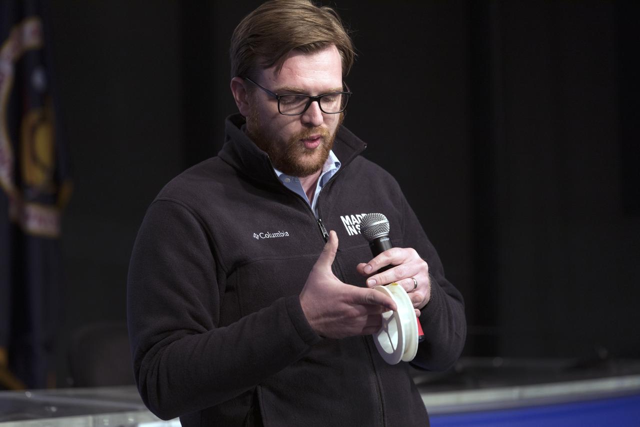
Andrew Rush, president and chief executive officer of Made in Space, discusses his company's Fiber Optics payload, with members of social media in the Kennedy Space Center’s Press Site auditorium. The briefing focused on research planned for launch to the International Space Station. The scientific materials and supplies will be aboard a Dragon spacecraft scheduled for liftoff from Cape Canaveral Air Force Station's Space Launch Complex 40 at 11:46 a.m. EST, on Dec. 12, 2017. The SpaceX Falcon 9 rocket will launch the company's 13th Commercial Resupply Services mission to the space station.

Deep Space Station 13 (DSS-13) at NASA's Goldstone Deep Space Communications Complex near Barstow, California – part of the agency's Deep Space Network – is a 34-meter (112-foot) experimental antenna that has been retrofitted with an optical terminal (the boxy instrument below the center of the antenna's dish). Since November 2023, DSS-13 has been tracking the downlink laser of the Deep Space Optical Communications (DSOC) experiment that is aboard NASA's Psyche mission, which launched on Oct. 13, 2023. In a first, the antenna also synchronously received radio-frequency signals from the spacecraft as it travels through deep space on its way to investigate the metal-rich asteroid Psyche. The laser signal collected by the camera is then transmitted through optical fiber that feeds into a cryogenically cooled semiconducting nanowire single photon detector. Designed and built by JPL's Microdevices Laboratory, the detector is identical to the one used at Caltech's Palomar Observatory, in San Diego County, California, that acts as DSOC's downlink ground station. Goldstone is one of three complexes that comprise NASA's Deep Space Network, which provides radio communications for all of the agency's interplanetary spacecraft and is also utilized for radio astronomy and radar observations of the solar system and the universe. NASA's Jet Propulsion Laboratory, a division of Caltech in Pasadena, California, manages the DSN for the agency. https://photojournal.jpl.nasa.gov/catalog/PIA26148
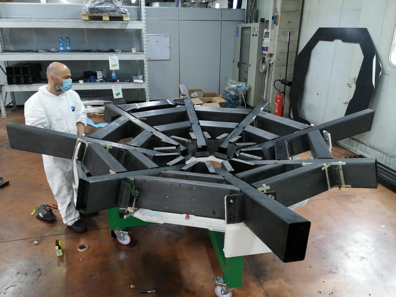
Known as the cradle, the structure that supports the primary mirror on NASA's Astrophysics Stratospheric Telescope for High Spectral Resolution Observations at Submillimeter-wavelengths mission, or ASTHROS, keeps the mirror panels aligned. Made from carbon fiber, it and must be both lightweight and extremely rigid. NASA contracted Media Lario, an optics company in Bosisio Parini, Italy, to design and produce ASTHROS' full telescope unit, including the primary mirror, a secondary mirror, and supporting structure (called the cradle). The cradle is shown here at Media Lario. The mission's main science goal is to study stellar feedback, the process by which living stars disperse and reshape clouds of gas and dust that may eventually form new stars. Feedback regulates star formation in many galaxies, and too much can halt star formation entirely. ASTHROS will look at several star-forming regions in our galaxy where feedback takes place, and at distant galaxies containing millions of stars to see how feedback plays out at large scales and in different environments. https://photojournal.jpl.nasa.gov/catalog/PIA25169
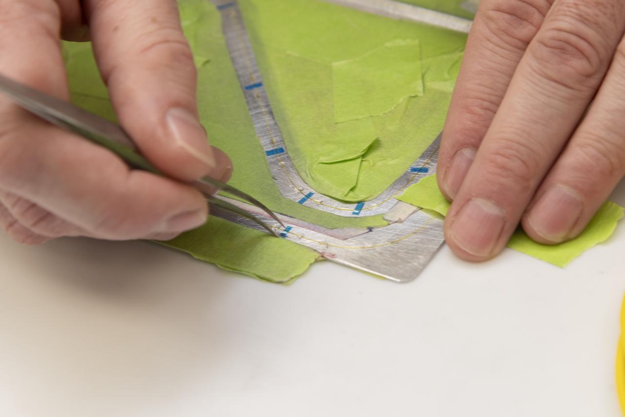
Engineering technician Jeff Howell removes thin pieces of tape from fiber used for a bonding process on the Mock Truss-Braced Wing 10-foot model at NASA’s Armstrong Flight Research Center in Edwards, California.
A new NASA-developed, laser-based space communication system will enable higher rates of satellite communications similar in capability to high-speed fiber optic networks on Earth. The space terminal for the Lunar Laser Communication Demonstration (LLCD), NASA's first high-data-rate laser communication system, was recently integrated onto the Lunar Atmosphere and Dust Environment Explorer (LADEE) spacecraft. LLCD will demonstrate laser communications from lunar orbit to Earth at six times the rate of the best modern-day advanced radio communication systems. Credit: NASA ----- What is LADEE? The Lunar Atmosphere and Dust Environment Explorer (LADEE) is designed to study the Moon's thin exosphere and the lunar dust environment. An "exosphere" is an atmosphere that is so thin and tenuous that molecules don't collide with each other. Studying the Moon's exosphere will help scientists understand other planetary bodies with exospheres too, like Mercury and some of Jupiter's bigger moons. The orbiter will determine the density, composition and temporal and spatial variability of the Moon's exosphere to help us understand where the species in the exosphere come from and the role of the solar wind, lunar surface and interior, and meteoric infall as sources. The mission will also examine the density and temporal and spatial variability of dust particles that may get lofted into the atmosphere. The mission also will test several new technologies, including a modular spacecraft bus that may reduce the cost of future deep space missions and demonstrate two-way high rate laser communication for the first time from the Moon. LADEE now is ready to launch when the window opens on Sept. 6, 2013. Read more: <a href="http://www.nasa.gov/ladee" rel="nofollow">www.nasa.gov/ladee</a> <b><a href="http://www.nasa.gov/audience/formedia/features/MP_Photo_Guidelines.html" rel="nofollow">NASA image use policy.</a></b> <b><a href="http://www.nasa.gov/centers/goddard/home/index.html" rel="nofollow">NASA Goddard Space Flight Center</a></b> enables NASA’s mission through four scientific endeavors: Earth Science, Heliophysics, Solar System Exploration, and Astrophysics. Goddard plays a leading role in NASA’s accomplishments by contributing compelling scientific knowledge to advance the Agency’s mission. <b>Follow us on <a href="http://twitter.com/NASA_GoddardPix" rel="nofollow">Twitter</a></b> <b>Like us on <a href="http://www.facebook.com/pages/Greenbelt-MD/NASA-Goddard/395013845897?ref=tsd" rel="nofollow">Facebook</a></b> <b>Find us on <a href="http://instagram.com/nasagoddard?vm=grid" rel="nofollow">Instagram</a></b>