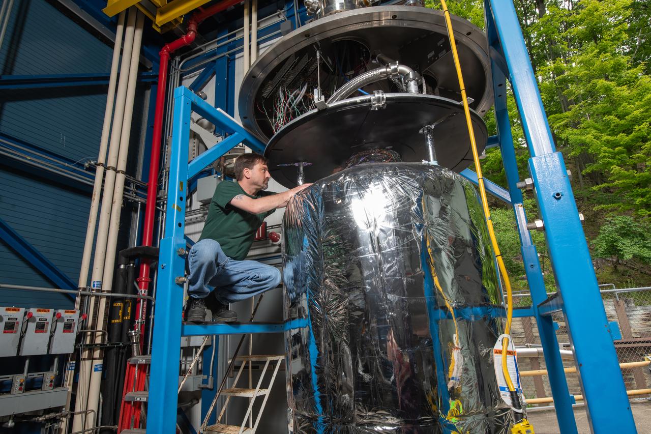
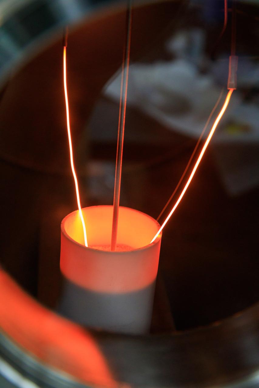
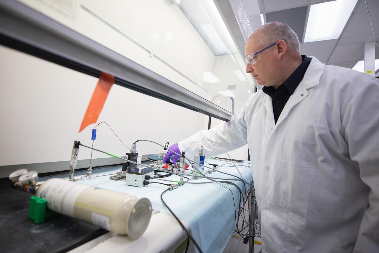
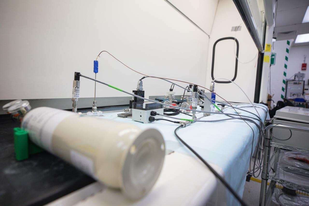
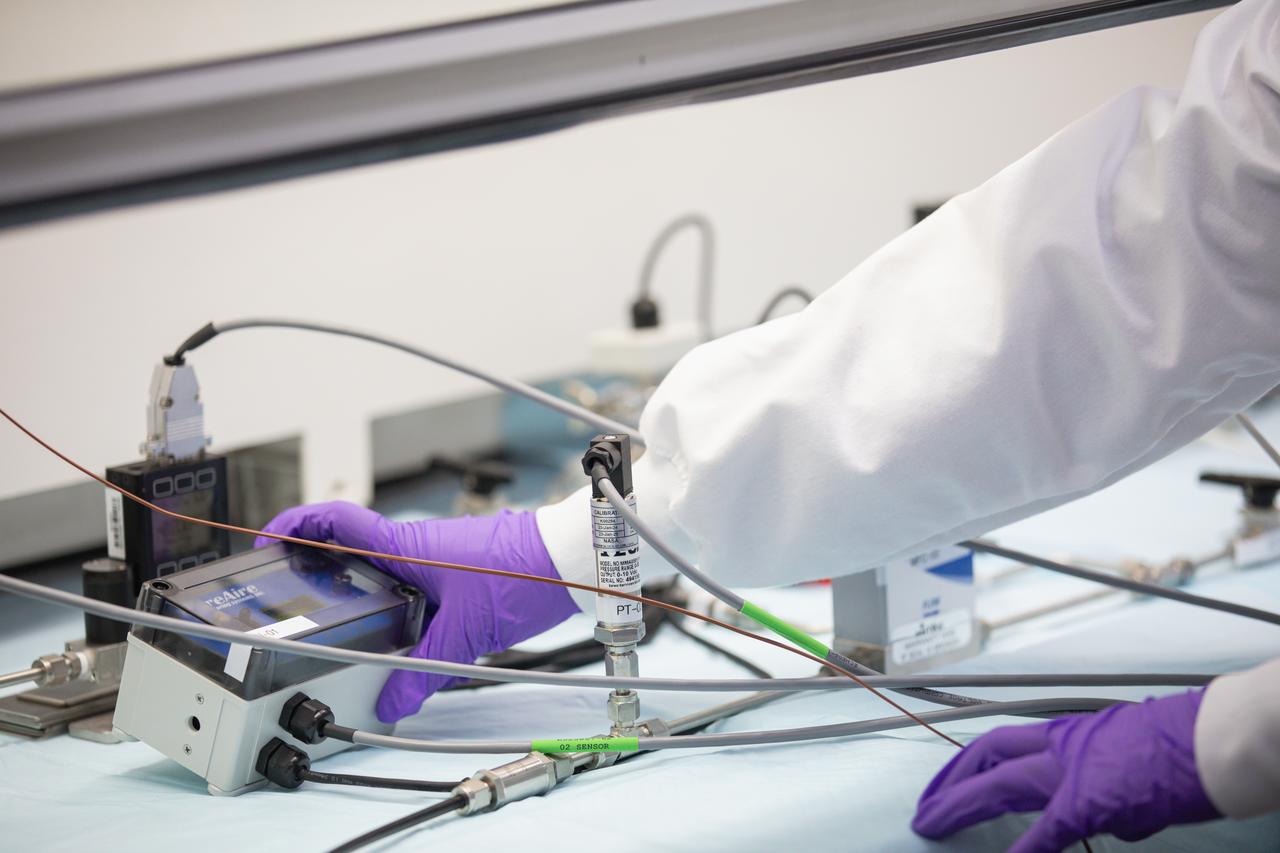
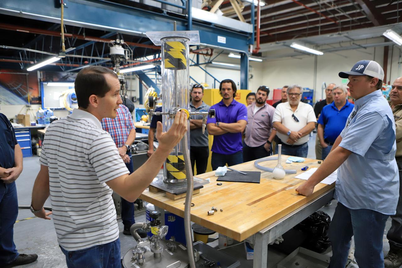
A tank is used in CryoFILL experiments to liquefy oxygen at minus 290 degrees Fahrenheit as it could be done on the Moon or Mars. The tests conducted at NASA Glenn Research Center, used Fiber Optic Sensing System (FOSS) developed by NASA Armstrong Flight Research Center, to measure oxygen temperatures inside the tank.
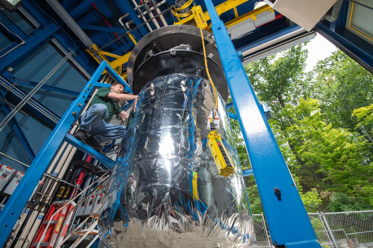
A tank is used in CryoFILL experiments to liquefy oxygen at minus 290 degrees Fahrenheit as it could be done on the Moon or Mars. The tests conducted at NASA Glenn Research Center, used Fiber Optic Sensing System (FOSS) developed by NASA Armstrong Flight Research Center, to measure oxygen temperatures inside the tank.
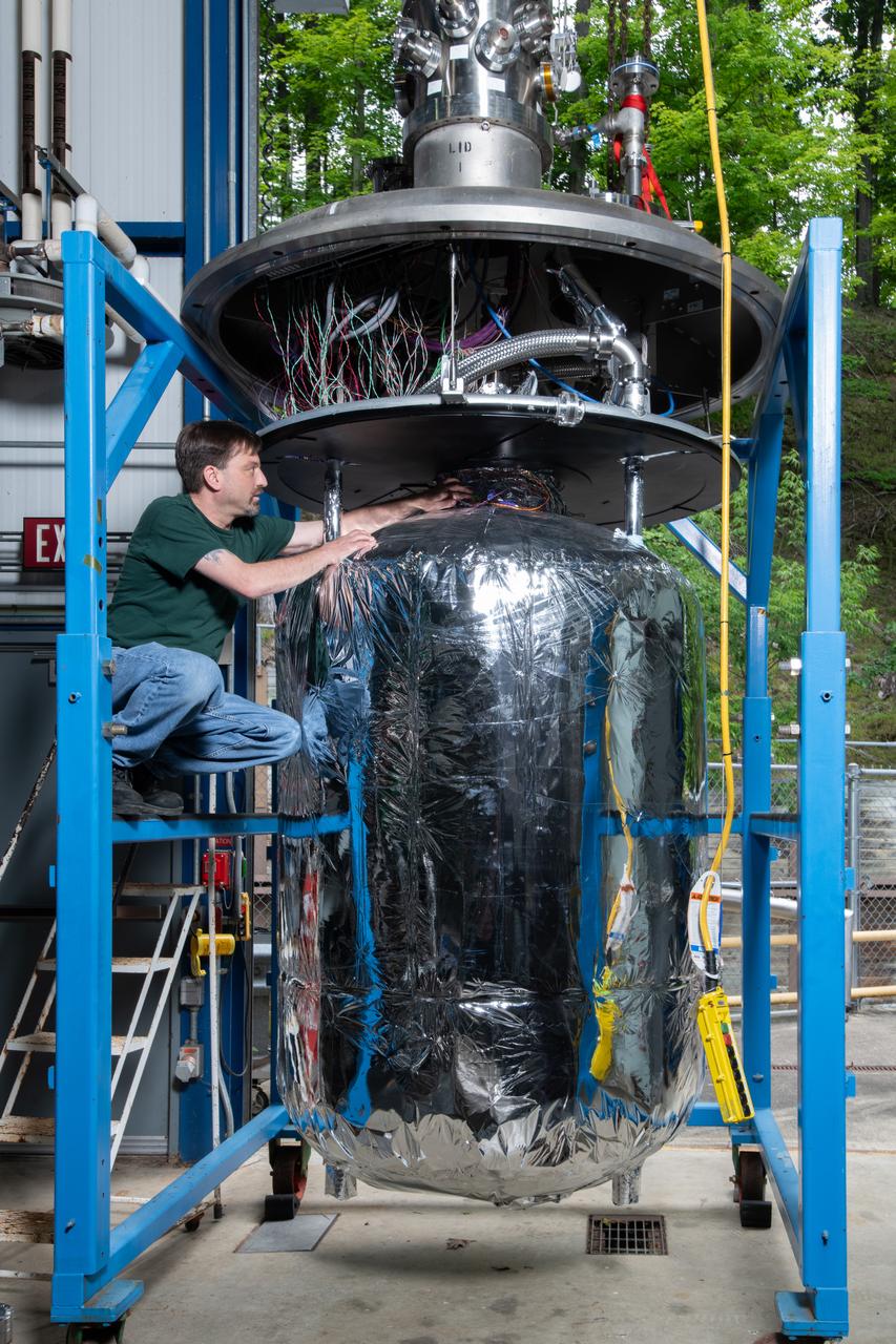
A tank is used in CryoFILL experiments to liquefy oxygen at minus 290 degrees Fahrenheit as it could be done on the Moon or Mars. The tests conducted at NASA Glenn Research Center, used Fiber Optic Sensing System (FOSS) developed by NASA Armstrong Flight Research Center, to measure oxygen temperatures inside the tank.
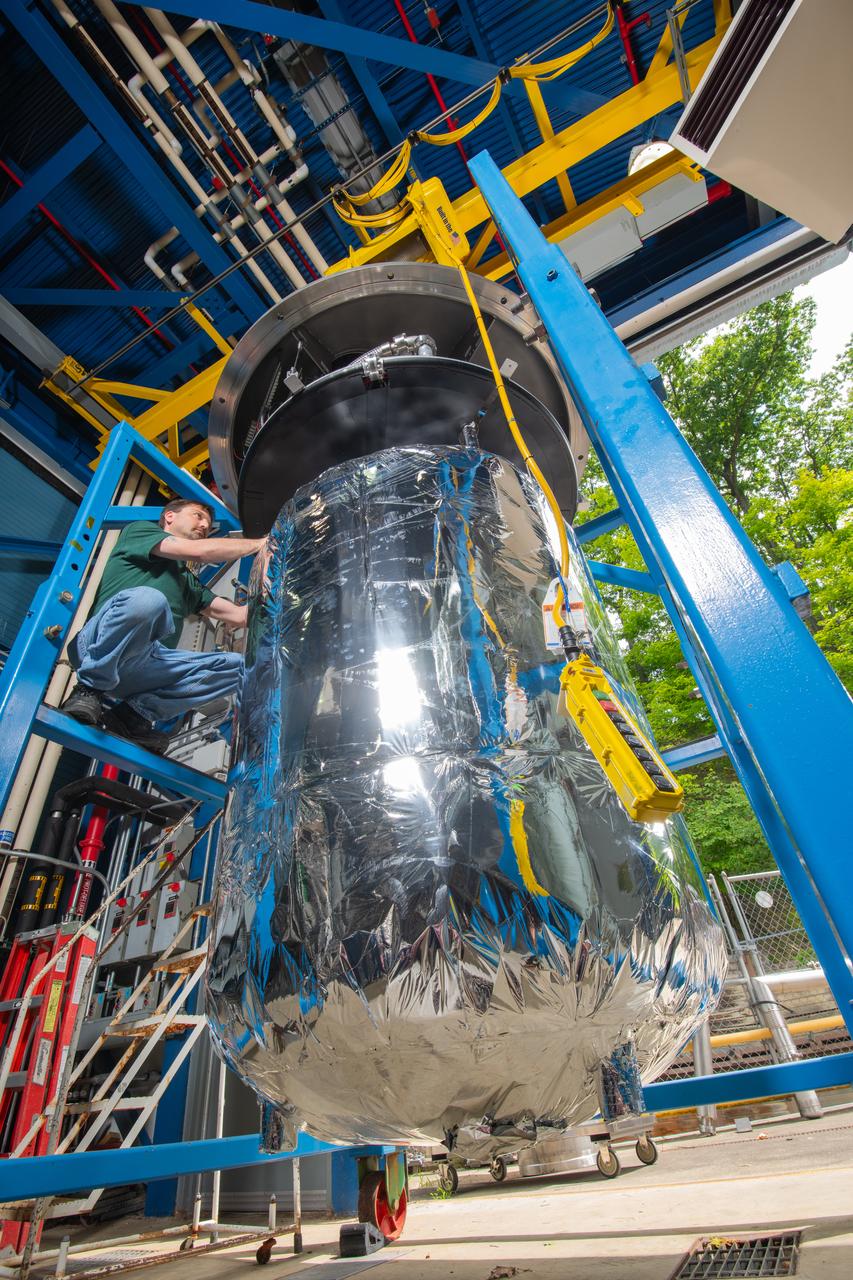
A tank is used in CryoFILL experiments to liquefy oxygen at minus 290 degrees Fahrenheit as it could be done on the Moon or Mars. The tests conducted at NASA Glenn Research Center, used Fiber Optic Sensing System (FOSS) developed by NASA Armstrong Flight Research Center, to measure oxygen temperatures inside the tank.
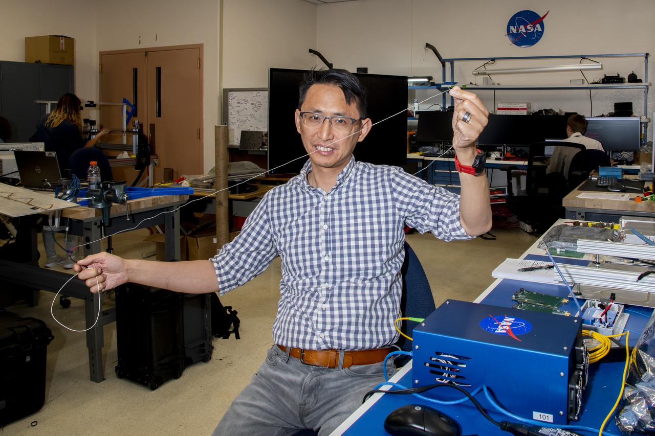
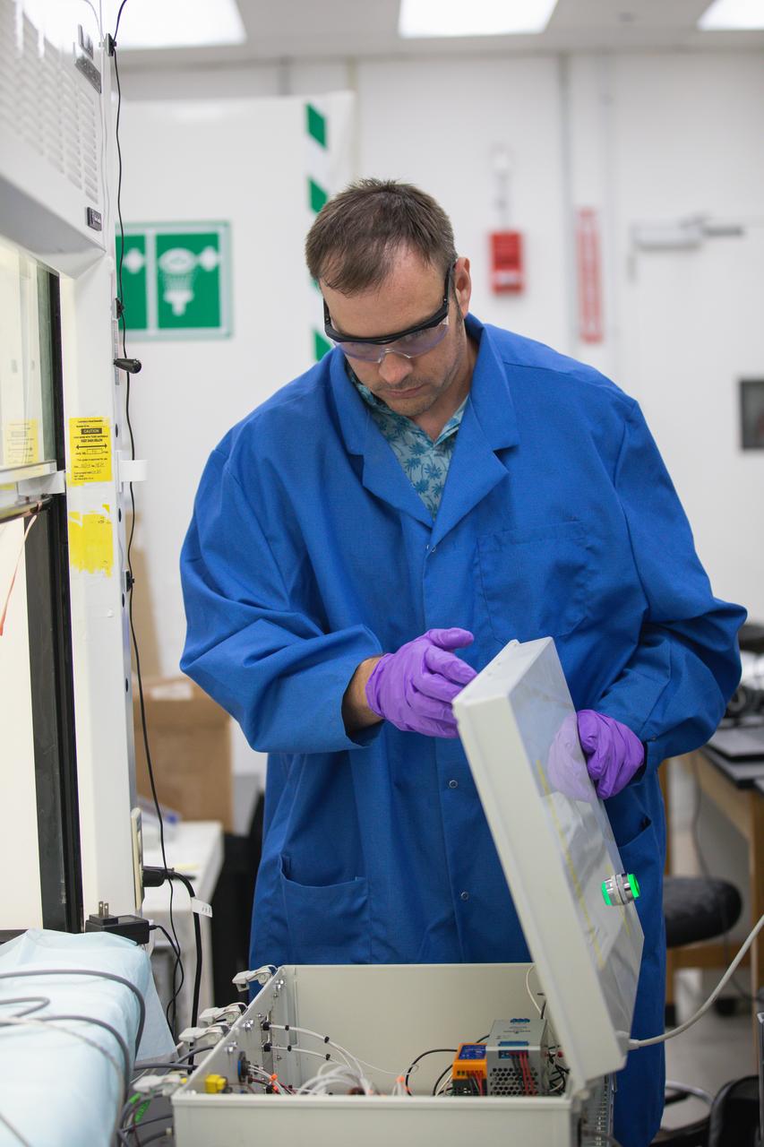
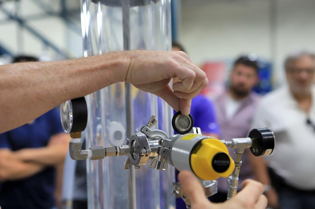
Patrick Chan, electronics engineer, and NASA Armstrong Flight Research Center’s FOSS portfolio project manager, shows a fiber used in a temperature sensing system. Armstrong’s Fiber Optic Sensing System was used to measure temperatures during tests aimed at turning oxygen into liquid oxygen. Testing was conducted at NASA’s Glenn Research Center in Cleveland, Ohio.
Inside a laboratory in the Neil A. Armstrong Operations and Checking Building at NASA’s Kennedy Space Center in Florida, testing is underway on the Molten Regolith Electrolysis (MRE) on Aug. 30, 2022. This is a high-temperature electrolytic process which aims to extract oxygen from the simulated lunar regolith. Extraction of oxygen on the lunar surface is critical to the agency’s Artemis program. Oxygen extracted from the Moon can be utilized for propellent to NASA’s lunar landers., breathable oxygen for astronauts, and a variety of other industrial and scientific applications for NASA’s future missions to the Moon.

An engineer conducts testing of the Molten Regolith Electrolysis (MRE) inside a laboratory in the Neil A. Armstrong Operations and Checkout Building at NASA’s Kennedy Space Center in Florida on Aug. 30, 2022. This is a high-temperature electrolytic process which aims to extract oxygen from the simulated lunar regolith. Extraction of oxygen on the lunar surface is critical to the agency’s Artemis program. Oxygen extracted from the Moon can be utilized for propellent to NASA’s lunar landers., breathable oxygen for astronauts, and a variety of other industrial and scientific applications for NASA’s future missions to the Moon.
Engineers conduct testing of the Molten Regolith Electrolysis (MRE) inside a laboratory in the Neil A. Armstrong Operations and Checkout Building at NASA’s Kennedy Space Center in Florida on Aug. 30, 2022. This is a high-temperature electrolytic process which aims to extract oxygen from the simulated lunar regolith. Extraction of oxygen on the lunar surface is critical to the agency’s Artemis program. Oxygen extracted from the Moon can be utilized for propellent to NASA’s lunar landers., breathable oxygen for astronauts, and a variety of other industrial and scientific applications for NASA’s future missions to the Moon.

An engineer conducts testing of the Molten Regolith Electrolysis (MRE) inside a laboratory in the Neil A. Armstrong Operations and Checkout Building at NASA’s Kennedy Space Center in Florida on Aug. 30, 2022. This is a high-temperature electrolytic process which aims to extract oxygen from the simulated lunar regolith. Extraction of oxygen on the lunar surface is critical to the agency’s Artemis program. Oxygen extracted from the Moon can be utilized for propellent to NASA’s lunar landers., breathable oxygen for astronauts, and a variety of other industrial and scientific applications for NASA’s future missions to the Moon.
Inside a laboratory in the Neil Armstrong Operations and Checking Building at NASA’s Kennedy Space Center in Florida, testing is underway on the Molten Regolith Electrolysis (MRE) on Sept. 13, 2022. This is a high-temperature electrolytic process which aims to extract oxygen from the simulated lunar regolith. Extraction of oxygen on the lunar surface is critical to the agency’s Artemis program. Oxygen extracted from the Moon can be utilized for propellent to NASA’s lunar landers., breathable oxygen for astronauts, and a variety of other industrial and scientific applications for NASA’s future missions to the Moon.
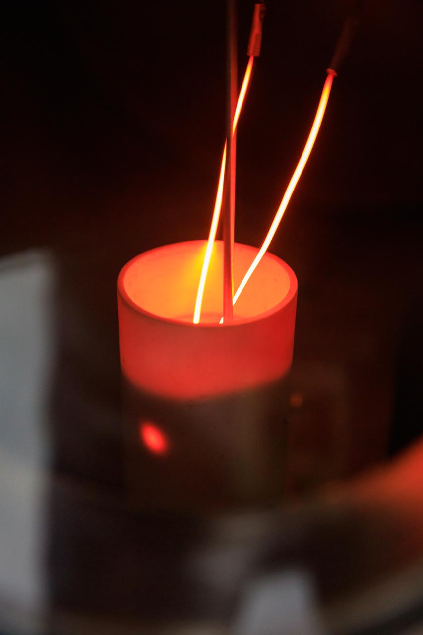
Inside a laboratory in the Neil A. Armstrong Operations and Checking Building at NASA’s Kennedy Space Center in Florida, testing is underway on the Molten Regolith Electrolysis (MRE) on Aug. 30, 2022. This is a high-temperature electrolytic process which aims to extract oxygen from the simulated lunar regolith. Extraction of oxygen on the lunar surface is critical to the agency’s Artemis program. Oxygen extracted from the Moon can be utilized for propellent to NASA’s lunar landers., breathable oxygen for astronauts, and a variety of other industrial and scientific applications for NASA’s future missions to the Moon.

Inside a laboratory in the Neil Armstrong Operations and Checking Building at NASA’s Kennedy Space Center in Florida, testing is underway on the Molten Regolith Electrolysis (MRE) on Sept. 13, 2022. This is a high-temperature electrolytic process which aims to extract oxygen from the simulated lunar regolith. Extraction of oxygen on the lunar surface is critical to the agency’s Artemis program. Oxygen extracted from the Moon can be utilized for propellent to NASA’s lunar landers., breathable oxygen for astronauts, and a variety of other industrial and scientific applications for NASA’s future missions to the Moon.
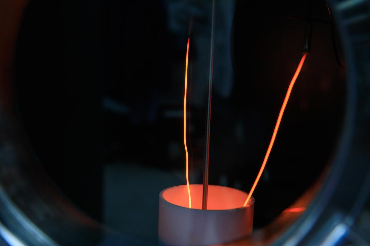
Inside a laboratory in the Neil Armstrong Operations and Checking Building at NASA’s Kennedy Space Center in Florida, testing is underway on the Molten Regolith Electrolysis (MRE) on Sept. 13, 2022. This is a high-temperature electrolytic process which aims to extract oxygen from the simulated lunar regolith. Extraction of oxygen on the lunar surface is critical to the agency’s Artemis program. Oxygen extracted from the Moon can be utilized for propellent to NASA’s lunar landers., breathable oxygen for astronauts, and a variety of other industrial and scientific applications for NASA’s future missions to the Moon.
Engineers conduct testing of the Molten Regolith Electrolysis (MRE) inside a laboratory in the Neil A. Armstrong Operations and Checkout Building at NASA’s Kennedy Space Center in Florida on Aug. 30, 2022. This is a high-temperature electrolytic process which aims to extract oxygen from the simulated lunar regolith. Extraction of oxygen on the lunar surface is critical to the agency’s Artemis program. Oxygen extracted from the Moon can be utilized for propellent to NASA’s lunar landers., breathable oxygen for astronauts, and a variety of other industrial and scientific applications for NASA’s future missions to the Moon.
An engineer conducts testing of the Molten Regolith Electrolysis (MRE) inside a laboratory in the Neil Armstrong Operations and Checkout Building at NASA’s Kennedy Space Center in Florida on Sept. 13, 2022. This is a high-temperature electrolytic process which aims to extract oxygen from the simulated lunar regolith. Extraction of oxygen on the lunar surface is critical to the agency’s Artemis program. Oxygen extracted from the Moon can be utilized for propellent to NASA’s lunar landers., breathable oxygen for astronauts, and a variety of other industrial and scientific applications for NASA’s future missions to the Moon.

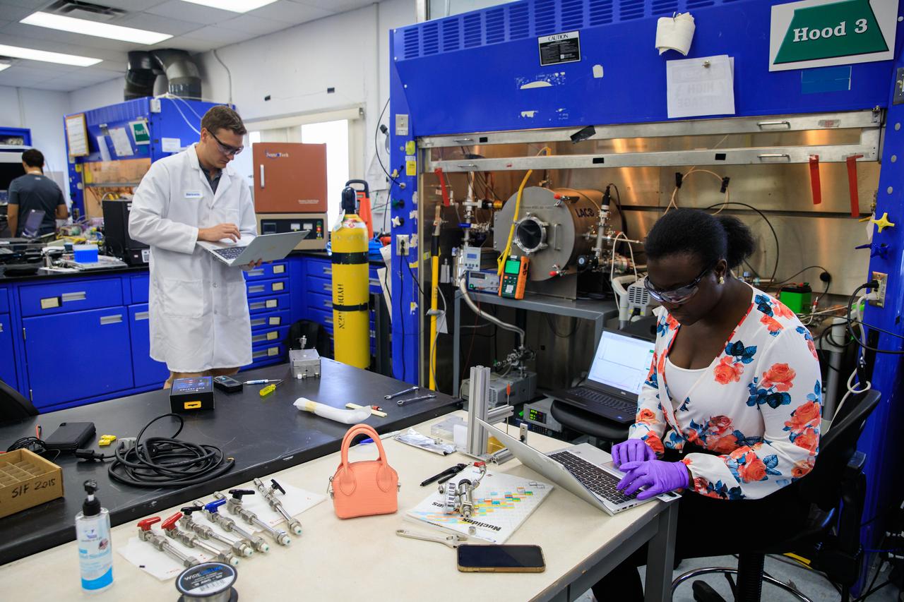
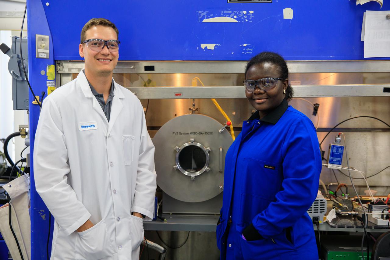
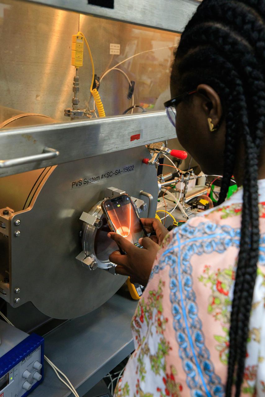
Deborah Efua Adu Essumang, system lead scientist, conducts testing of the Volatile Monitoring Oxygen Measurement Subsystem (VMOMS) for Molten Regolith Electrolysis (MRE) inside a laboratory in the Neil A. Armstrong Operations and Checkout Building at NASA’s Kennedy Space Center in Florida on April 19, 2024. The high-temperature electrolytic process aims to extract oxygen from simulated lunar regolith which will be critical to the agency’s Artemis campaign. Oxygen extracted from the Moon can be utilized for propellent to NASA’s lunar landers, breathable oxygen for astronauts, and a variety of other industrial and scientific applications for NASA’s future missions to the Moon.
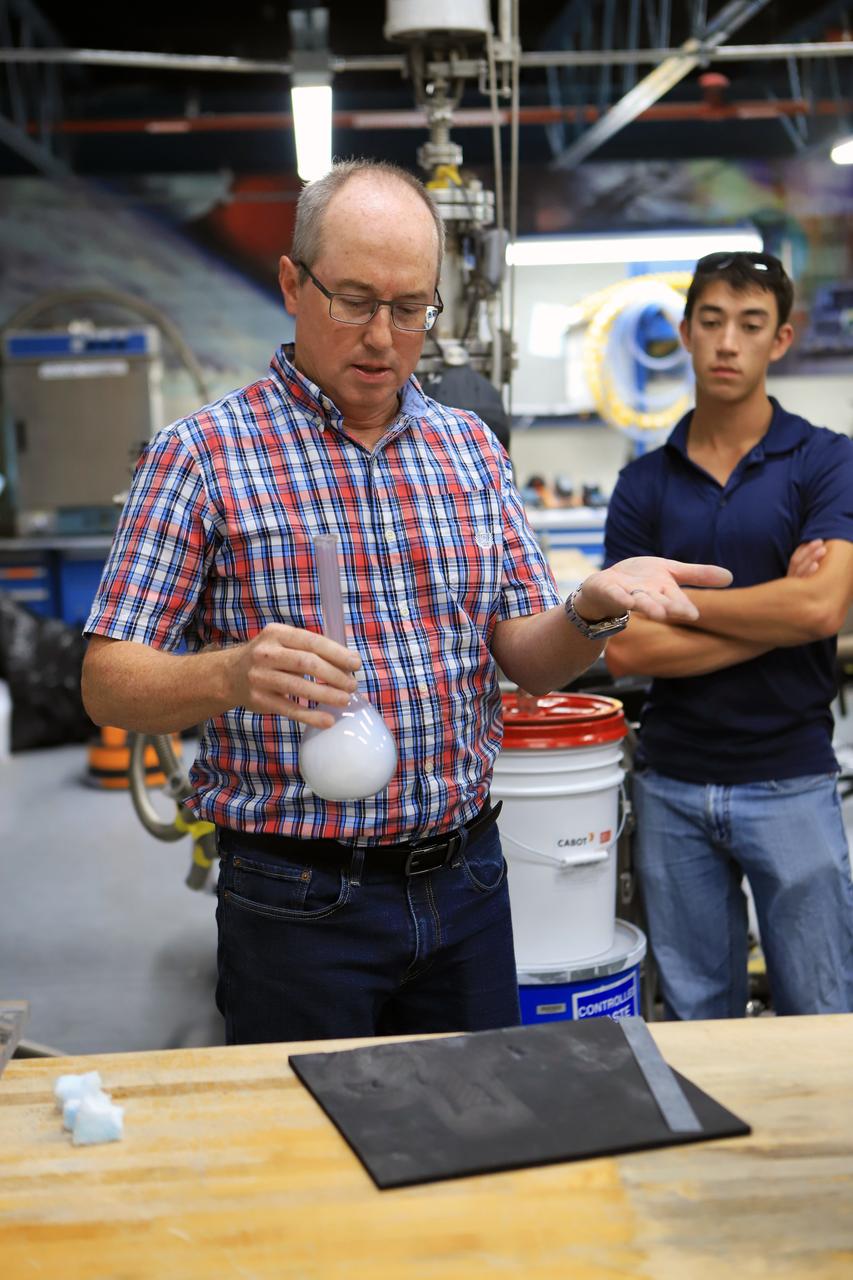
Dr. Joel Olson, subject matter expert, conducts testing of the Volatile Monitoring Volatile Monitoring Oxygen Measurement Subsystem (VMOMS) for Molten Regolith Electrolysis (MRE) inside a laboratory in the Neil A. Armstrong Operations and Checkout Building at NASA’s Kennedy Space Center in Florida on April 19, 2024. The high-temperature electrolytic process aims to extract oxygen from simulated lunar regolith which will be critical to the agency’s Artemis campaign. Oxygen extracted from the Moon can be utilized for propellent to NASA’s lunar landers, breathable oxygen for astronauts, and a variety of other industrial and scientific applications for NASA’s future missions to the Moon.
Beau Peacock, software engineer, conducts testing of the Volatile Monitoring Oxygen Measurement Subsystem (VMOMS) for Molten Regolith Electrolysis (MRE) inside a laboratory in the Neil A. Armstrong Operations and Checkout Building at NASA’s Kennedy Space Center in Florida on April 19, 2024. The high-temperature electrolytic process aims to extract oxygen from simulated lunar regolith which will be critical to the agency’s Artemis campaign. Oxygen extracted from the Moon can be utilized for propellent to NASA’s lunar landers, breathable oxygen for astronauts, and a variety of other industrial and scientific applications for NASA’s future missions to the Moon.
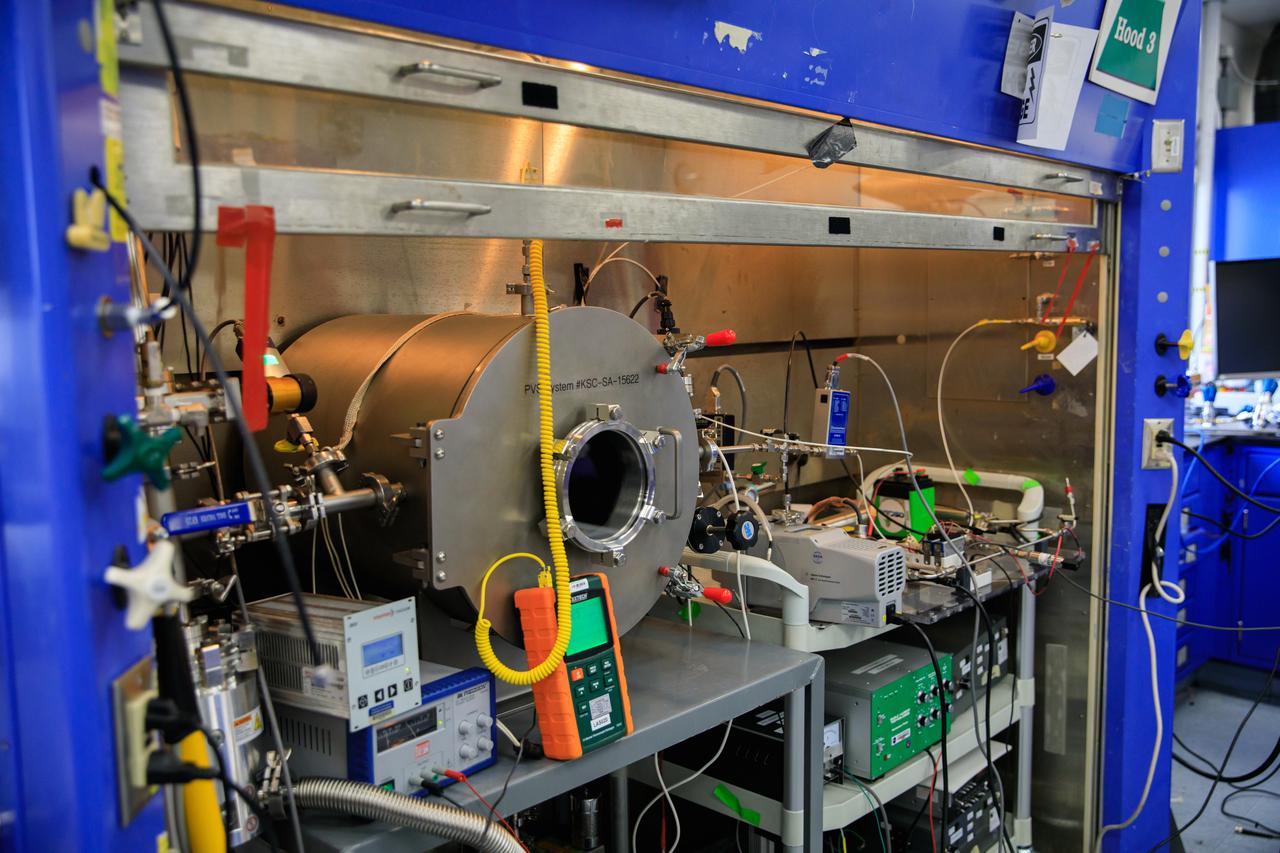
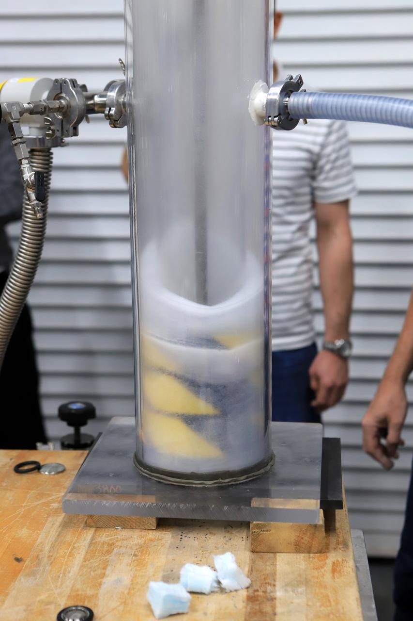
Inside a laboratory in the Neil A. Armstrong Operations and Checking Building at NASA’s Kennedy Space Center in Florida, testing is underway with the Volatile Monitoring Oxygen Measurement Subsystem (VMOMS) for Molten Regolith Electrolysis (MRE) on April 19, 2024. The high-temperature electrolytic process aims to extract oxygen from simulated lunar regolith, which will be critical to the agency’s Artemis campaign. Oxygen extracted from the Moon can be utilized for propellent to NASA’s lunar landers, breathable oxygen for astronauts, and a variety of other industrial and scientific applications for NASA’s future missions to the Moon.
Inside a laboratory in the Neil A. Armstrong Operations and Checking Building at NASA’s Kennedy Space Center in Florida, testing is underway with the Volatile Monitoring Oxygen Measurement Subsystem (VMOMS) for Molten Regolith Electrolysis (MRE) on April 19, 2024. The high-temperature electrolytic process aims to extract oxygen from simulated lunar regolith, which will be critical to the agency’s Artemis campaign. Oxygen extracted from the Moon can be utilized for propellent to NASA’s lunar landers, breathable oxygen for astronauts, and a variety of other industrial and scientific applications for NASA’s future missions to the Moon.
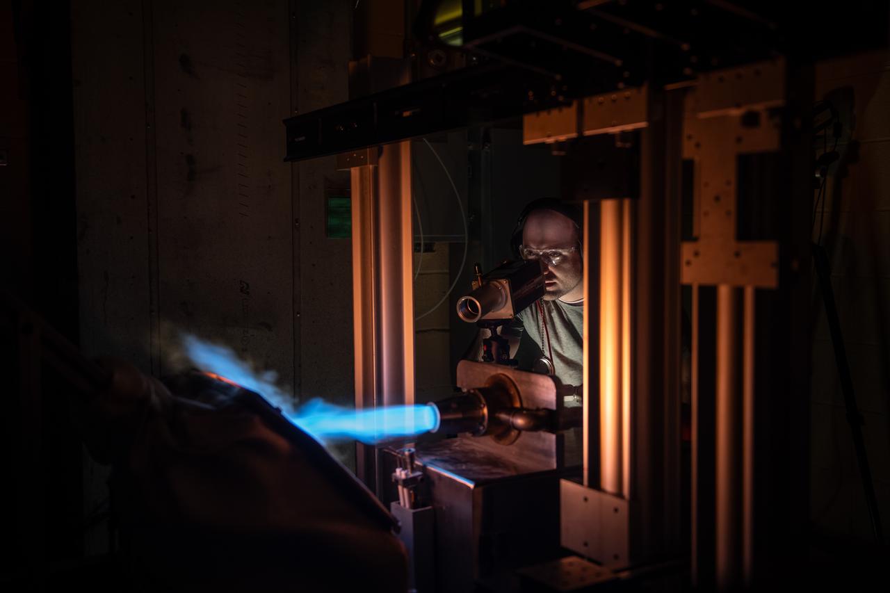
NASA Glenn’s Natural Gas/Oxygen Burner Rig is used to study the high temperature performance of various metal alloys, ceramics, and protective coatings for aero and space propulsion systems. The burner rig provides an easily accessible and economical method to simulate engine operating conditions to understand thermomechanical and thermochemical degradation of materials and structures. In the photo, Materials Research Engineer Michael Presby uses an infrared pyrometer to monitor the surface temperature of the material for a test on February 23, 2024. Photo Credit: (NASA/Sara Lowthian-Hanna)
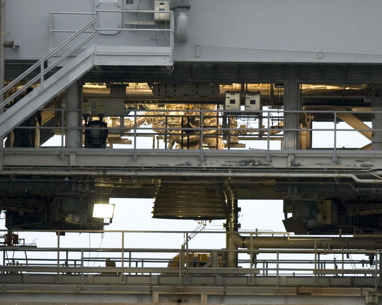
COLD FLOW - Liquid oxygen runs through the piping on Stennis Space Center's A-1 Test Stand on Dec. 18 to test the ability of the J-2X engine's Powerpack 1A to withstand the temperature change and pressure. Just visible above and to the right of the test article's nozzle is a frosty pipe, indicating the supercold fuel is flowing as it should.
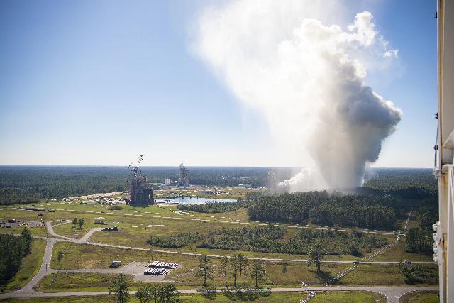
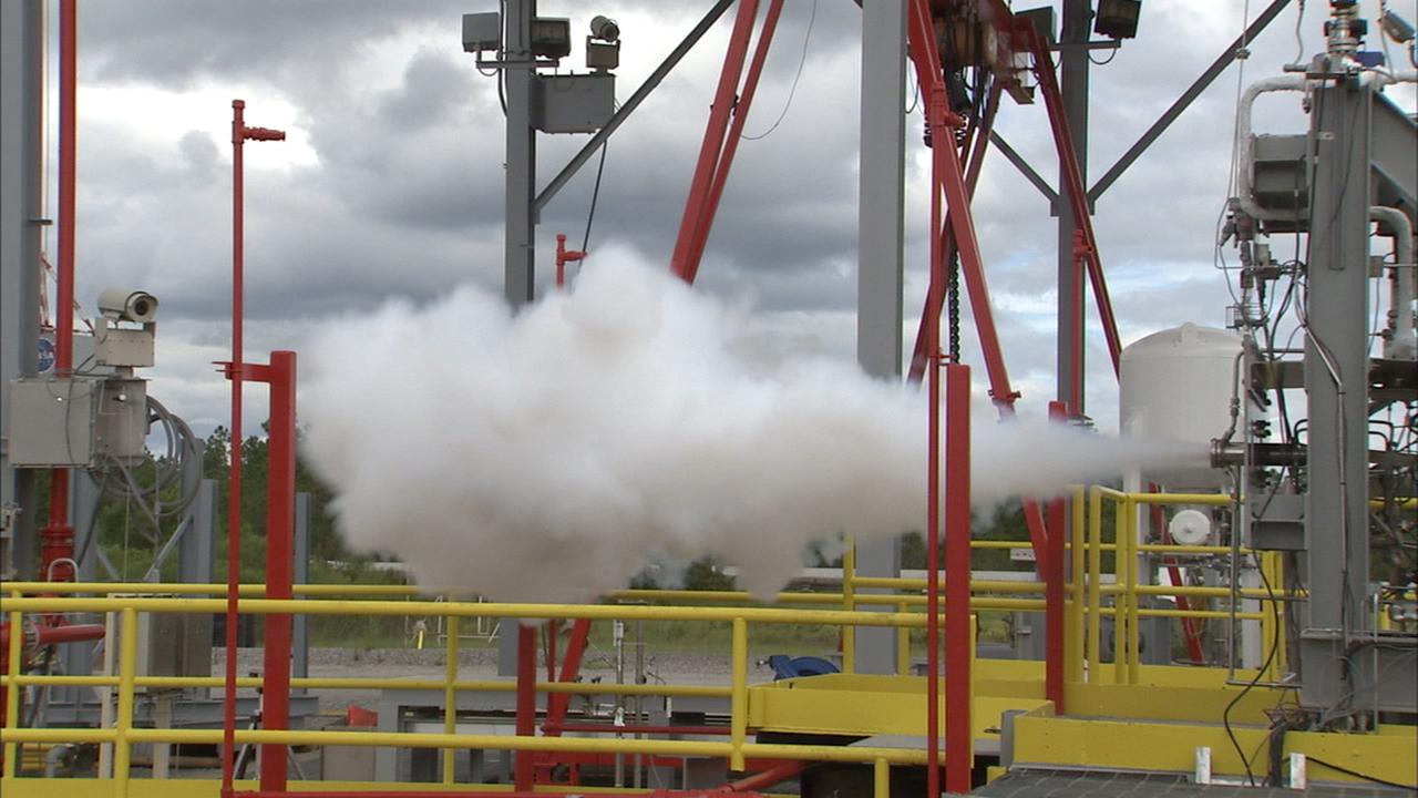
The RS-25 certification test series begins Oct. 17. When the liquid hydrogen and liquid oxygen propellants mix and ignite, an extremely high temperature exhaust, of up to 6,000-degrees Fahrenheit, mixes with water to form steam that exits the flame deflector and rises into the atmosphere, forming a cloud that subsequently cools.
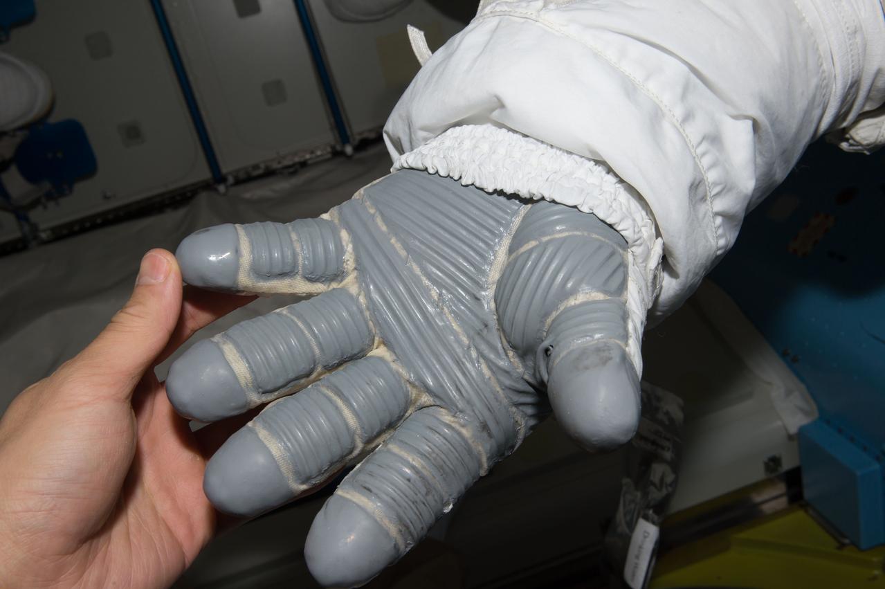
ss048e061332 (08/19/2016) --- Checking the space gloves before and after a spacewalk is part of the detailed check list astronauts go through to provide absolute safety. Both NASA astronaut Jeff Williams and Kate Rubens took part in the important inspections before and after their 19 Aug 2016 spacewalk to install a new docking adapter . A cut in the glove could subject the astronaut to the extreme temperatures of outer space and the escape of oxygen, both of which could be fatal.
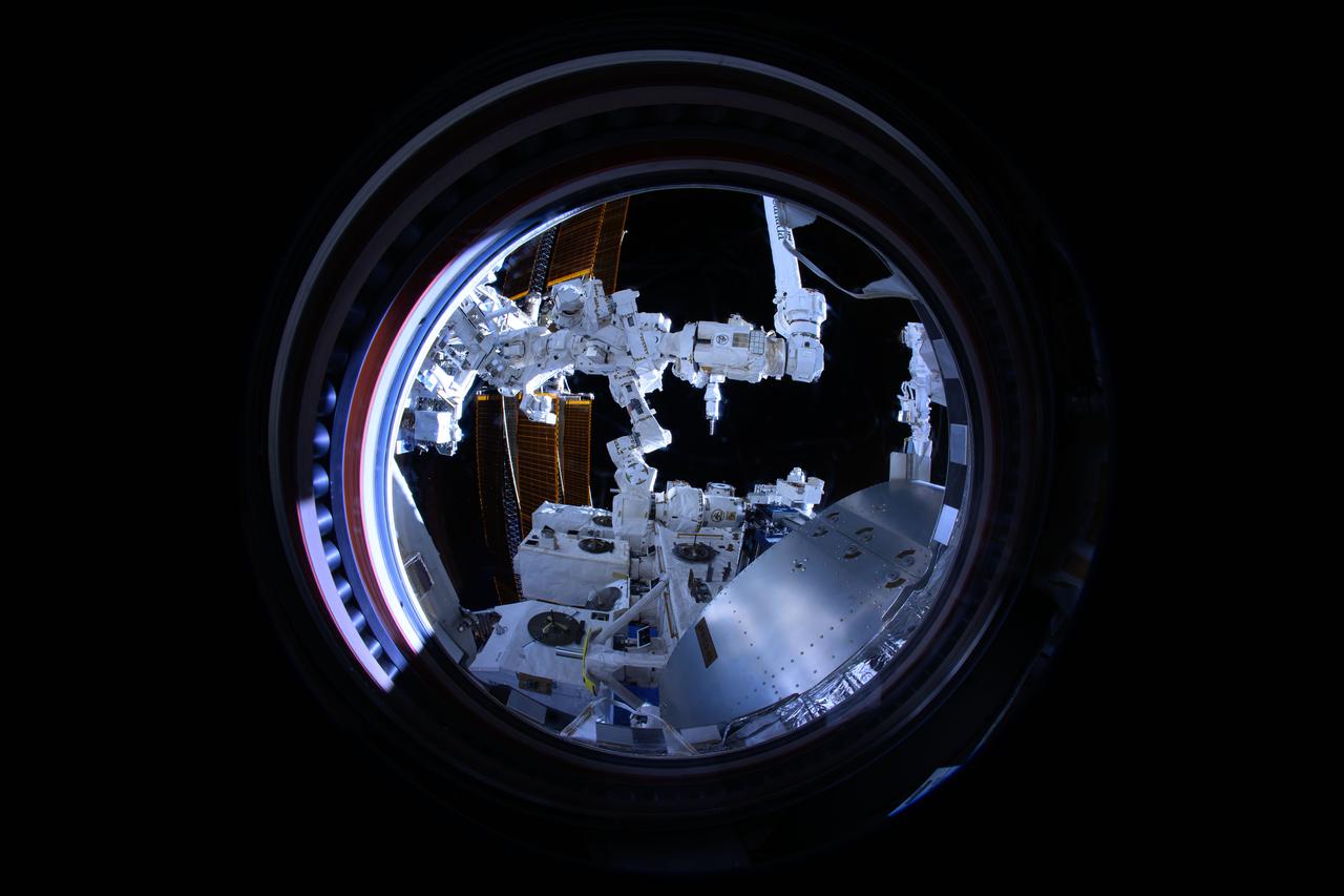
iss072e189571 (11/16/2024) --- The Canadarm2 robotic arm removes Materials ISS Experiment (MISSE) science carriers from the Kibo laboratory module's airlock. The MISSE Flight Facility mounted outside the International Space Station allows researchers to test the performance and durability of materials and devices. This is done by exposing items of interest to everything that makes the space environment harsh, including radiation, highly reactive atomic oxygen, microgravity, and extreme temperatures.
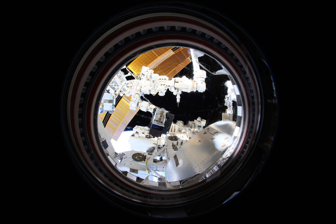
iss072e189789 (11/16/2024) --- The Canadarm2 robotic arm removes Materials ISS Experiment (MISSE) science carriers from the Kibo laboratory module's airlock. The MISSE Flight Facility mounted outside the International Space Station allows researchers to test the performance and durability of materials and devices. This is done by exposing items of interest to everything that makes the space environment harsh, including radiation, highly reactive atomic oxygen, microgravity, and extreme temperatures.
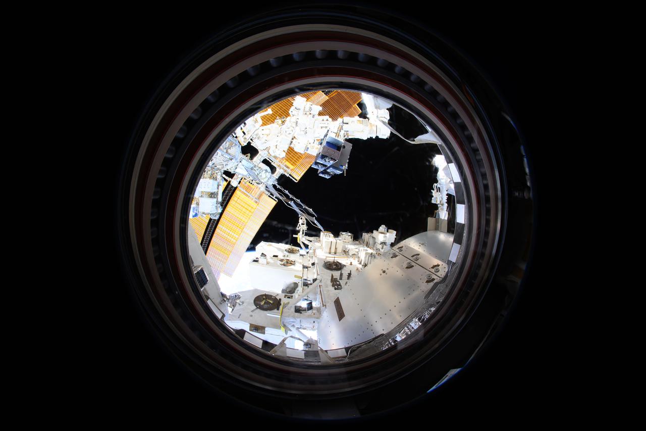
iss072e189797 (11/16/2024) --- The Canadarm2 robotic arm removes Materials ISS Experiment (MISSE) science carriers from the Kibo laboratory module's airlock. The MISSE Flight Facility mounted outside the International Space Station allows researchers to test the performance and durability of materials and devices. This is done by exposing items of interest to everything that makes the space environment harsh, including radiation, highly reactive atomic oxygen, microgravity, and extreme temperatures.
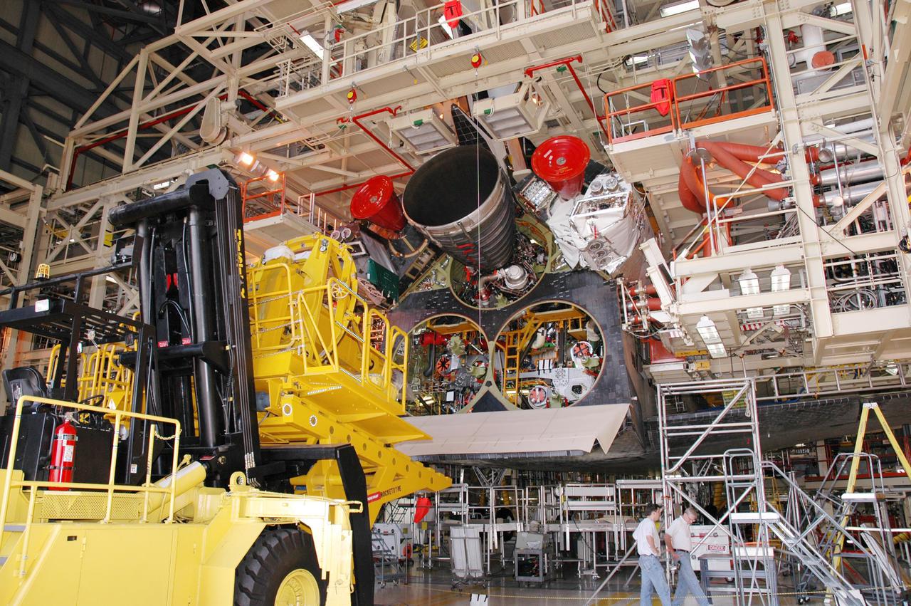
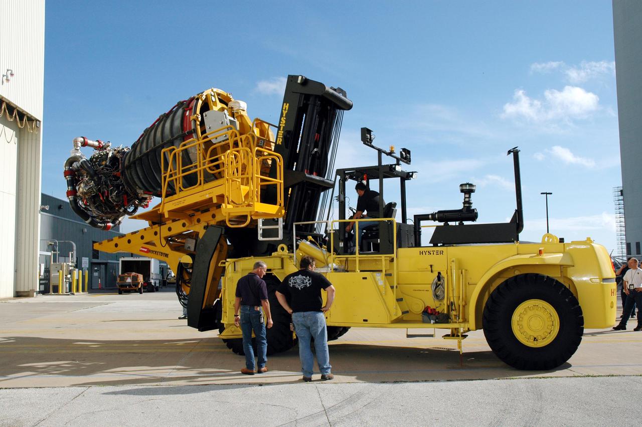
KENNEDY SPACE CENTER, FLA. - In the Orbiter Processing Facility, the Hyster lift backs away from the orbiter Discovery after placing a Space Shuttle Main Engine (SSME) into position for installation. Discovery is the vehicle designated for the Return to Flight mission STS-114. Overall, an SSME weighs approximately 7,000 pounds. An SSME operates at greater temperature extremes than any mechanical system in common use today. The liquid hydrogen fuel is -423 degrees Fahrenheit, the second coldest liquid on Earth. When the hydrogen is burned with liquid oxygen, the temperature in the engine's combustion chamber reaches +6000 degrees Fahrenheit -- that's higher than the boiling point of Iron. The maximum equivalent horsepower developed by the three SSMEs is just over 37 million horsepower. The energy released by the three SSMEs is equivalent to the output of 23 Hoover Dams.
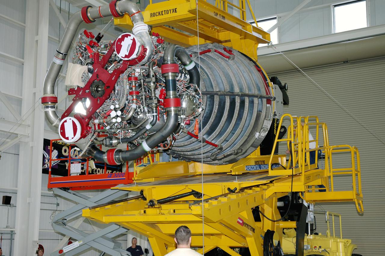
KENNEDY SPACE CENTER, FLA. - This Space Shuttle Main Engine (SSME) is slowly moved from the SSME Shop to the Orbiter Processing Facility where it will be installed in the orbiter Discovery for Return to Flight mission STS-114. This is the third SSME to be installed in Discovery. Overall, an SSME weighs approximately 7,000 pounds. An SSME operates at greater temperature extremes than any mechanical system in common use today. The liquid hydrogen fuel is -423 degrees Fahrenheit, the second coldest liquid on Earth. When the hydrogen is burned with liquid oxygen, the temperature in the engine's combustion chamber reaches +6000 degrees Fahrenheit -- higher than the boiling point of iron. Each SSME is controlled by its own computer, which checks the health of the engines 50 times per second during countdown and ascent. The controller can shut an engine down if it detects a problem.
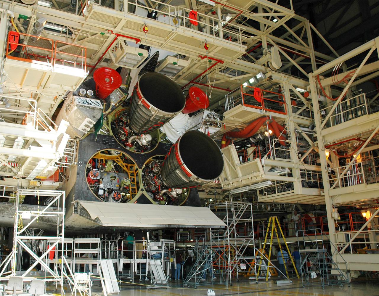
KENNEDY SPACE CENTER, FLA. - The second Space Shuttle Main Engine (SSME) has been installed on the orbiter Discovery in the Orbiter Processing Facility. Discovery is the vehicle designated for the Return to Flight mission STS-114. Overall, an SSME weighs approximately 7,000 pounds. An SSME operates at greater temperature extremes than any mechanical system in common use today. The liquid hydrogen fuel is -423 degrees Fahrenheit, the second coldest liquid on Earth. When the hydrogen is burned with liquid oxygen, the temperature in the engine's combustion chamber reaches +6000 degrees Fahrenheit -- that's higher than the boiling point of Iron. Each SSME is controlled by its own computer, which checks the health of the engines 50 times per second during countdown and ascent. The controller can shut an engine down if it detects a problem. The SSMEs are tested at Stennis Space Center in Mississippi.
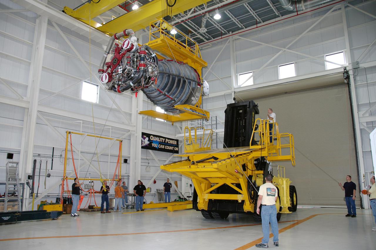
KENNEDY SPACE CENTER, FLA. - In the Space Shuttle Main Engine (SSME) Shop, the SSME is lifted and moved toward the Hyster lift that will transport it to the Orbiter Processing Facility. There it will be installed in the orbiter Discovery for Return to Flight mission STS-114. This is the third SSME to be installed in Discovery. Overall, an SSME weighs approximately 7,000 pounds. An SSME operates at greater temperature extremes than any mechanical system in common use today. The liquid hydrogen fuel is -423 degrees Fahrenheit, the second coldest liquid on Earth. When the hydrogen is burned with liquid oxygen, the temperature in the engine's combustion chamber reaches +6000 degrees Fahrenheit -- higher than the boiling point of iron. Each SSME is controlled by its own computer, which checks the health of the engines 50 times per second during countdown and ascent. The controller can shut an engine down if it detects a problem.
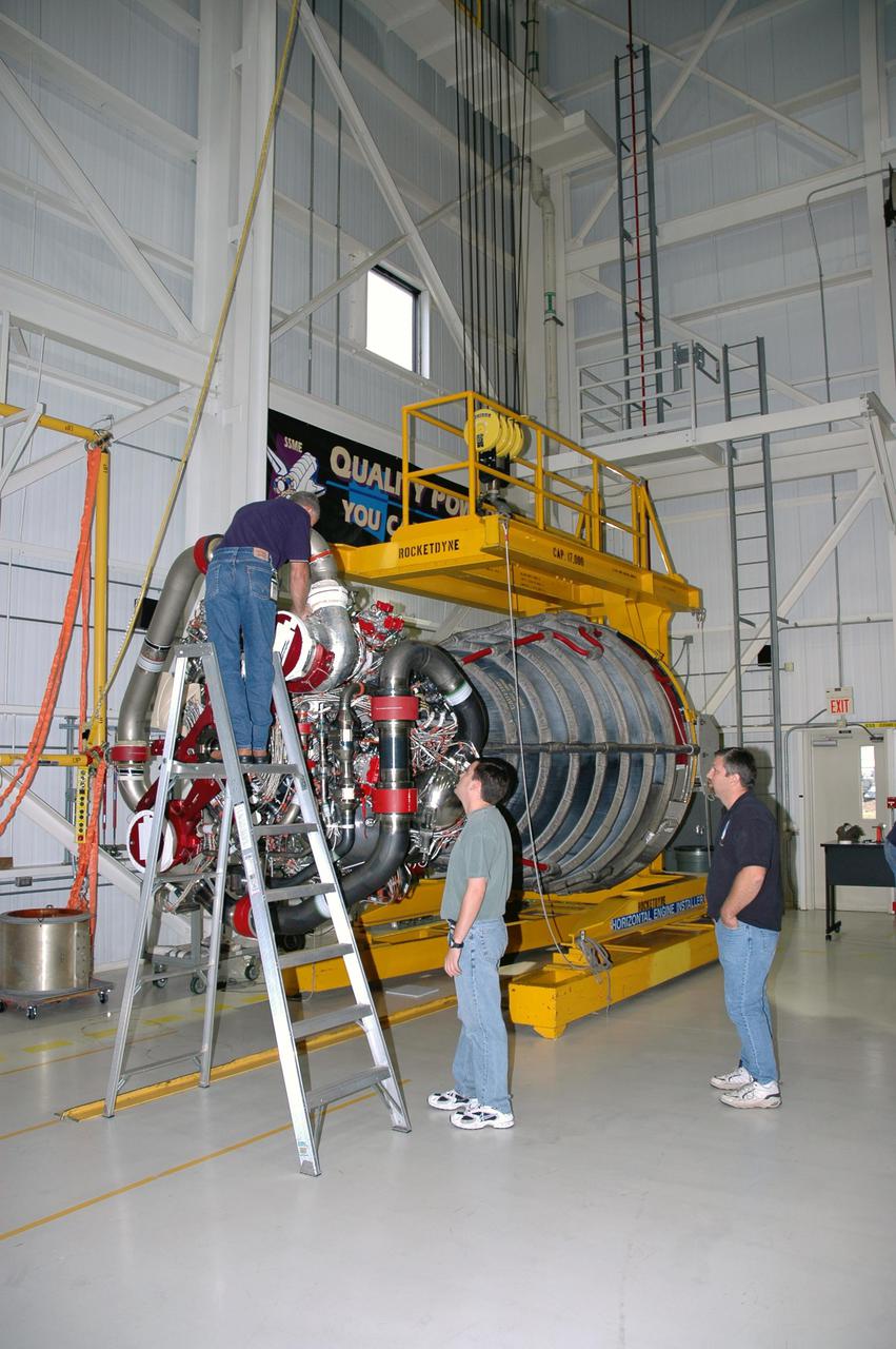
KENNEDY SPACE CENTER, FLA. - Workers in the Space Shuttle Main Engine (SSME) Shop prepare the engine for its move to the Hyster lift and transport to the Orbiter Processing Facility. There it will be installed in the orbiter Discovery for Return to Flight mission STS-114. This is the third SSME to be installed in Discovery. Overall, an SSME weighs approximately 7,000 pounds. An SSME operates at greater temperature extremes than any mechanical system in common use today. The liquid hydrogen fuel is -423 degrees Fahrenheit, the second coldest liquid on Earth. When the hydrogen is burned with liquid oxygen, the temperature in the engine's combustion chamber reaches +6000 degrees Fahrenheit -- higher than the boiling point of iron. Each SSME is controlled by its own computer, which checks the health of the engines 50 times per second during countdown and ascent. The controller can shut an engine down if it detects a problem.
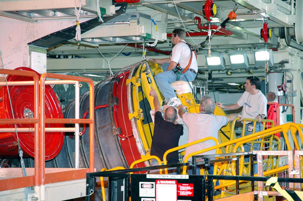
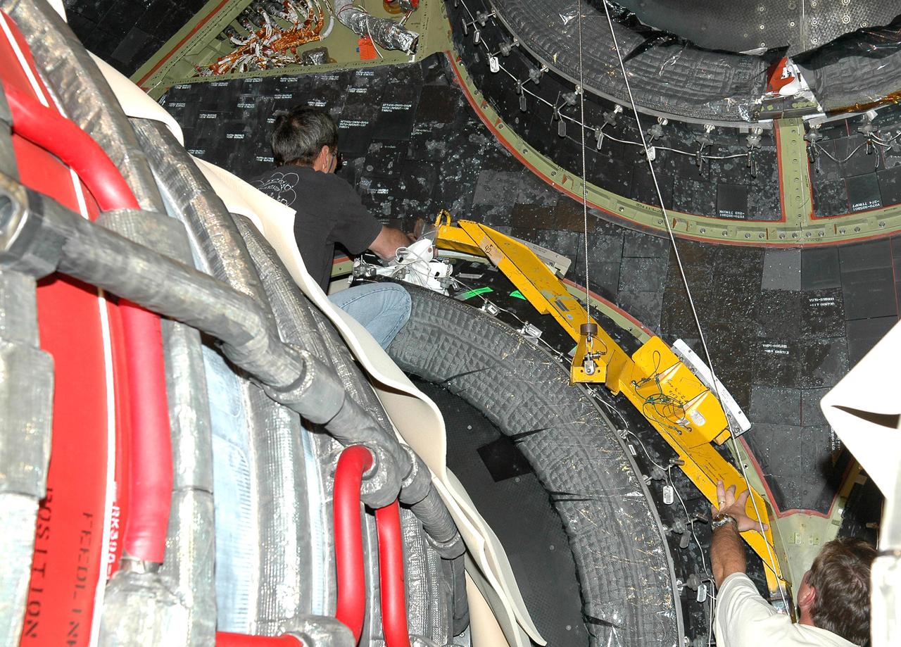
KENNEDY SPACE CENTER, FLA. - In the Orbiter Processing Facility, a technician appears to ride the Space Shuttle Main Engine (SSME) as he maneuvers the SSME on the Hyster lift into position for installation on Discovery, the vehicle designated for the Return to Flight mission STS-114. Overall, an SSME weighs approximately 7,000 pounds. An SSME operates at greater temperature extremes than any mechanical system in common use today. The liquid hydrogen fuel is -423 degrees Fahrenheit, the second coldest liquid on Earth. When the hydrogen is burned with liquid oxygen, the temperature in the engine's combustion chamber reaches +6000 degrees Fahrenheit -- that's higher than the boiling point of Iron. The maximum equivalent horsepower developed by the three SSMEs is just over 37 million horsepower. The energy released by the three SSMEs is equivalent to the output of 23 Hoover Dams.
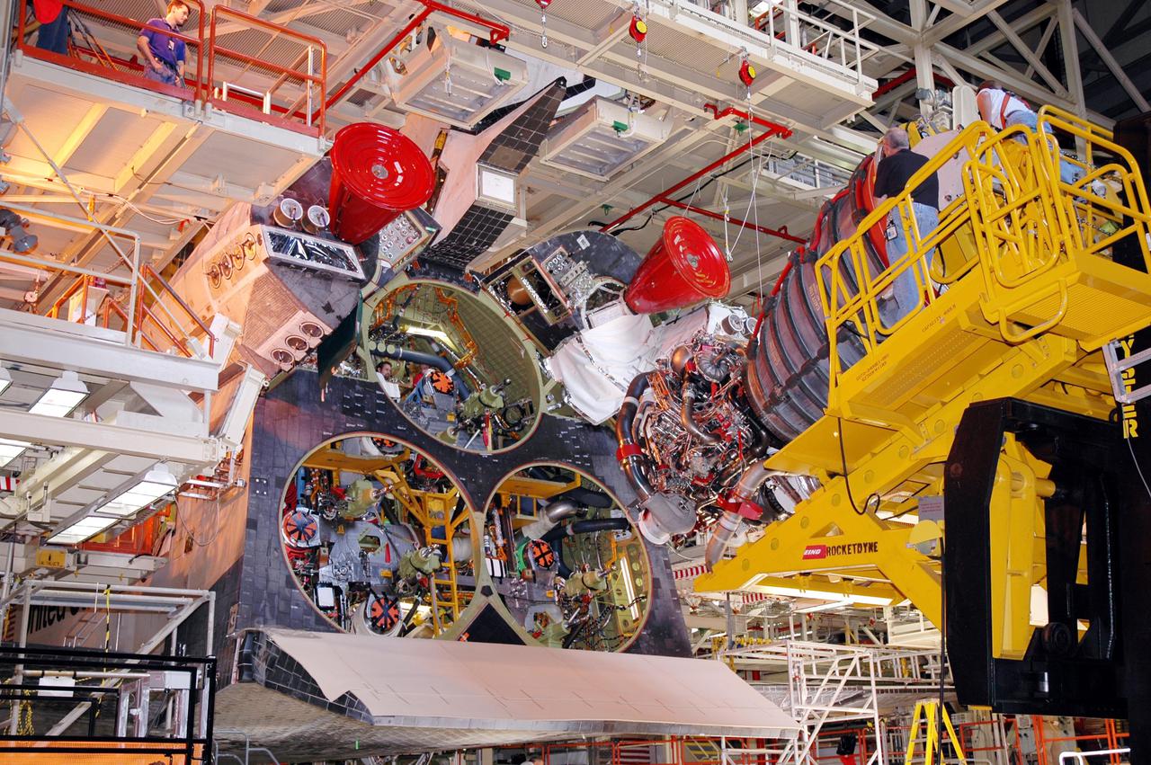
KENNEDY SPACE CENTER, FLA. - In the Orbiter Processing Facility, Discovery waits as the first of three Space Shuttle Main Engines (SSME) moves into position for installation on Discovery, the vehicle designated for the Return to Flight mission STS-114. Overall, an SSME weighs approximately 7,000 pounds. An SSME operates at greater temperature extremes than any mechanical system in common use today. The liquid hydrogen fuel is -423 degrees Fahrenheit, the second coldest liquid on Earth. When the hydrogen is burned with liquid oxygen, the temperature in the engine's combustion chamber reaches +6000 degrees Fahrenheit -- that's higher than the boiling point of Iron. The maximum equivalent horsepower developed by the three SSMEs is just over 37 million horsepower. The energy released by the three SSMEs is equivalent to the output of 23 Hoover Dams.
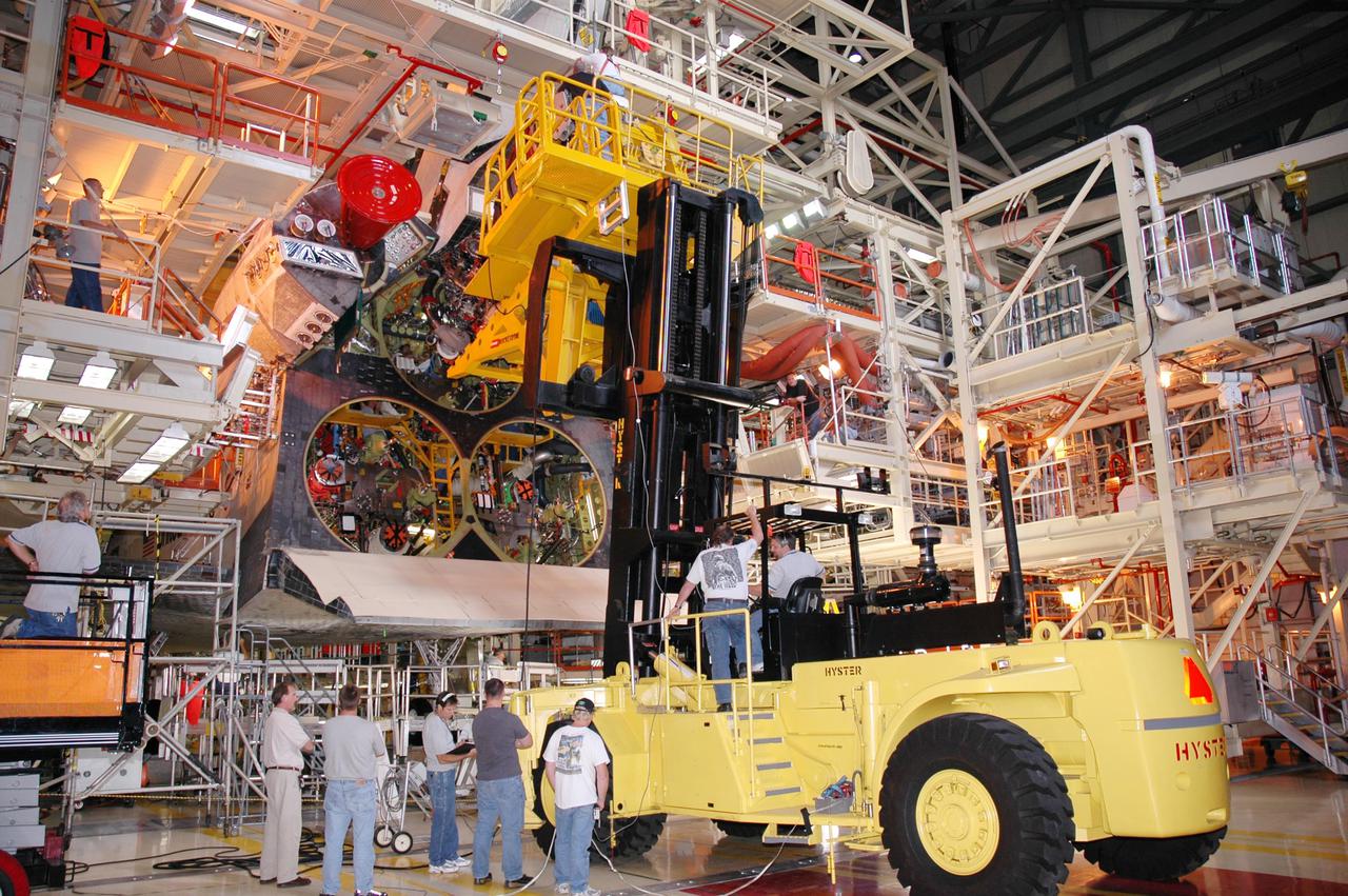
KENNEDY SPACE CENTER, FLA. - In the Orbiter Processing Facility, technicians wait below while a Hyster lift moves the first of three Space Shuttle Main Engines (SSME) into position above for installation on Discovery, the vehicle designated for the Return to Flight mission STS-114. Overall, an SSME weighs approximately 7,000 pounds. An SSME operates at greater temperature extremes than any mechanical system in common use today. The liquid hydrogen fuel is -423 degrees Fahrenheit, the second coldest liquid on Earth. When the hydrogen is burned with liquid oxygen, the temperature in the engine's combustion chamber reaches +6000 degrees Fahrenheit -- that's higher than the boiling point of Iron. The maximum equivalent horsepower developed by the three SSMEs is just over 37 million horsepower. The energy released by the three SSMEs is equivalent to the output of 23 Hoover Dams.

KENNEDY SPACE CENTER, FLA. - In Orbiter Processing Facility bay 1, Dave Fentris, an aft mechanical technician with United Space Alliance, attaches a dome heat shield to one of three Space Shuttle Main Engines (SSME) on the orbiter Atlantis. The shields provide protection for the orbiter against the high temperatures generated by an SSME. The liquid hydrogen fuel is - 423 degrees Fahrenheit, the second coldest liquid on Earth. When the hydrogen is burned with liquid oxygen, the temperature in the engine's combustion chamber reaches +6000 degrees Fahrenheit - that’s higher than the boiling point of iron. Each SSME is controlled by its own computer, which checks the health of the engines 50 times per second during countdown and ascent. The controller can shut an engine down if it detects a problem. Atlantis is scheduled to launch in July on mission STS-121.
KENNEDY SPACE CENTER, FLA. - Dave Fentris (upper left) and Gary Austin , aft mechanical technicians with United Space Alliance, are attaching dome heat shields to Space Shuttle Main Engines (SSME) on the orbiter Atlantis in Orbiter Processing Facility bay 1. The shields provide protection for the orbiter against the high temperatures generated by an SSME. The liquid hydrogen fuel is - 423 degrees Fahrenheit, the second coldest liquid on Earth. When the hydrogen is burned with liquid oxygen, the temperature in the engine's combustion chamber reaches +6000 degrees Fahrenheit - that’s higher than the boiling point of iron. Each SSME is controlled by its own computer, which checks the health of the engines 50 times per second during countdown and ascent. The controller can shut an engine down if it detects a problem. Atlantis is scheduled to launch in July on mission STS-121.
KENNEDY SPACE CENTER, FLA. - Dave Fentris (upper left) and Gary Austin , aft mechanical technicians with United Space Alliance, are attaching dome heat shields to Space Shuttle Main Engines (SSME) on the orbiter Atlantis in Orbiter Processing Facility bay 1. The shields provide protection for the orbiter against the high temperatures generated by an SSME. The liquid hydrogen fuel is - 423 degrees Fahrenheit, the second coldest liquid on Earth. When the hydrogen is burned with liquid oxygen, the temperature in the engine's combustion chamber reaches +6000 degrees Fahrenheit - that’s higher than the boiling point of iron. Each SSME is controlled by its own computer, which checks the health of the engines 50 times per second during countdown and ascent. The controller can shut an engine down if it detects a problem. Atlantis is scheduled to launch in July on mission STS-121.

KENNEDY SPACE CENTER, FLA. - In the Orbiter Processing Facility, a technician (lower right) watches from inside as a Space Shuttle Main Engine (SSME) on the Hyster lift is maneuvered into position on Discovery, the vehicle designated for the Return to Flight mission STS-114. Overall, an SSME weighs approximately 7,000 pounds. An SSME operates at greater temperature extremes than any mechanical system in common use today. The liquid hydrogen fuel is -423 degrees Fahrenheit, the second coldest liquid on Earth. When the hydrogen is burned with liquid oxygen, the temperature in the engine's combustion chamber reaches +6000 degrees Fahrenheit -- that's higher than the boiling point of Iron. The maximum equivalent horsepower developed by the three SSMEs is just over 37 million horsepower. The energy released by the three SSMEs is equivalent to the output of 23 Hoover Dams.
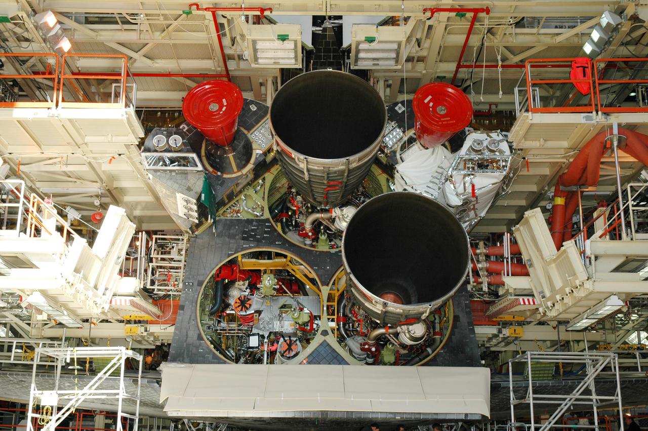
KENNEDY SPACE CENTER, FLA. - The second Space Shuttle Main Engine (SSME) has been installed on the orbiter Discovery in the Orbiter Processing Facility. Discovery is the vehicle designated for the Return to Flight mission STS-114. Overall, an SSME weighs approximately 7,000 pounds. An SSME operates at greater temperature extremes than any mechanical system in common use today. The liquid hydrogen fuel is -423 degrees Fahrenheit, the second coldest liquid on Earth. When the hydrogen is burned with liquid oxygen, the temperature in the engine's combustion chamber reaches +6000 degrees Fahrenheit -- that's higher than the boiling point of Iron. Each SSME is controlled by its own computer, which checks the health of the engines 50 times per second during countdown and ascent. The controller can shut an engine down if it detects a problem. The SSMEs are tested at Stennis Space Center in Mississippi.
KENNEDY SPACE CENTER, FLA. - In the Space Shuttle Main Engine (SSME) Shop, the SSME is lowered onto the Hyster lift for transport to the Orbiter Processing Facility. There it will be installed in the orbiter Discovery for Return to Flight mission STS-114. This is the third SSME to be installed in Discovery. Overall, an SSME weighs approximately 7,000 pounds. An SSME operates at greater temperature extremes than any mechanical system in common use today. The liquid hydrogen fuel is -423 degrees Fahrenheit, the second coldest liquid on Earth. When the hydrogen is burned with liquid oxygen, the temperature in the engine's combustion chamber reaches +6000 degrees Fahrenheit -- higher than the boiling point of iron. Each SSME is controlled by its own computer, which checks the health of the engines 50 times per second during countdown and ascent. The controller can shut an engine down if it detects a problem.
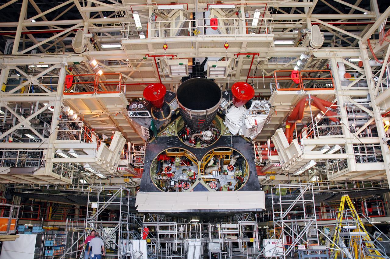
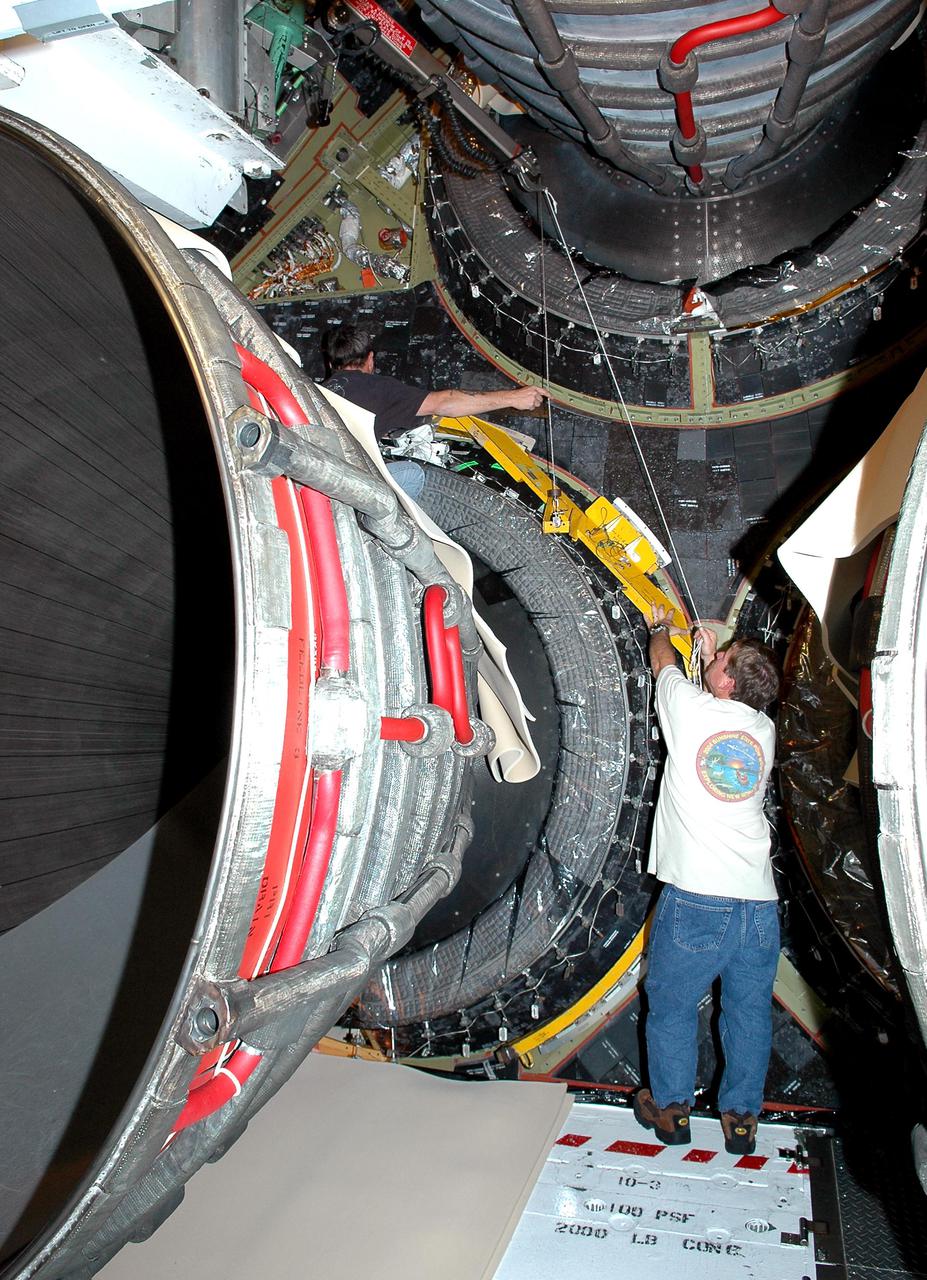
KENNEDY SPACE CENTER, FLA. - In this view from the floor of the Orbiter Processing Facility, the first of three Space Shuttle Main Engines (SSME) is seen after installation. Discovery is the vehicle designated for the Return to Flight mission STS-114. Overall, an SSME weighs approximately 7,000 pounds. An SSME operates at greater temperature extremes than any mechanical system in common use today. The liquid hydrogen fuel is -423 degrees Fahrenheit, the second coldest liquid on Earth. When the hydrogen is burned with liquid oxygen, the temperature in the engine's combustion chamber reaches +6000 degrees Fahrenheit -- that's higher than the boiling point of Iron. The maximum equivalent horsepower developed by the three SSMEs is just over 37 million horsepower. The energy released by the three SSMEs is equivalent to the output of 23 Hoover Dams.
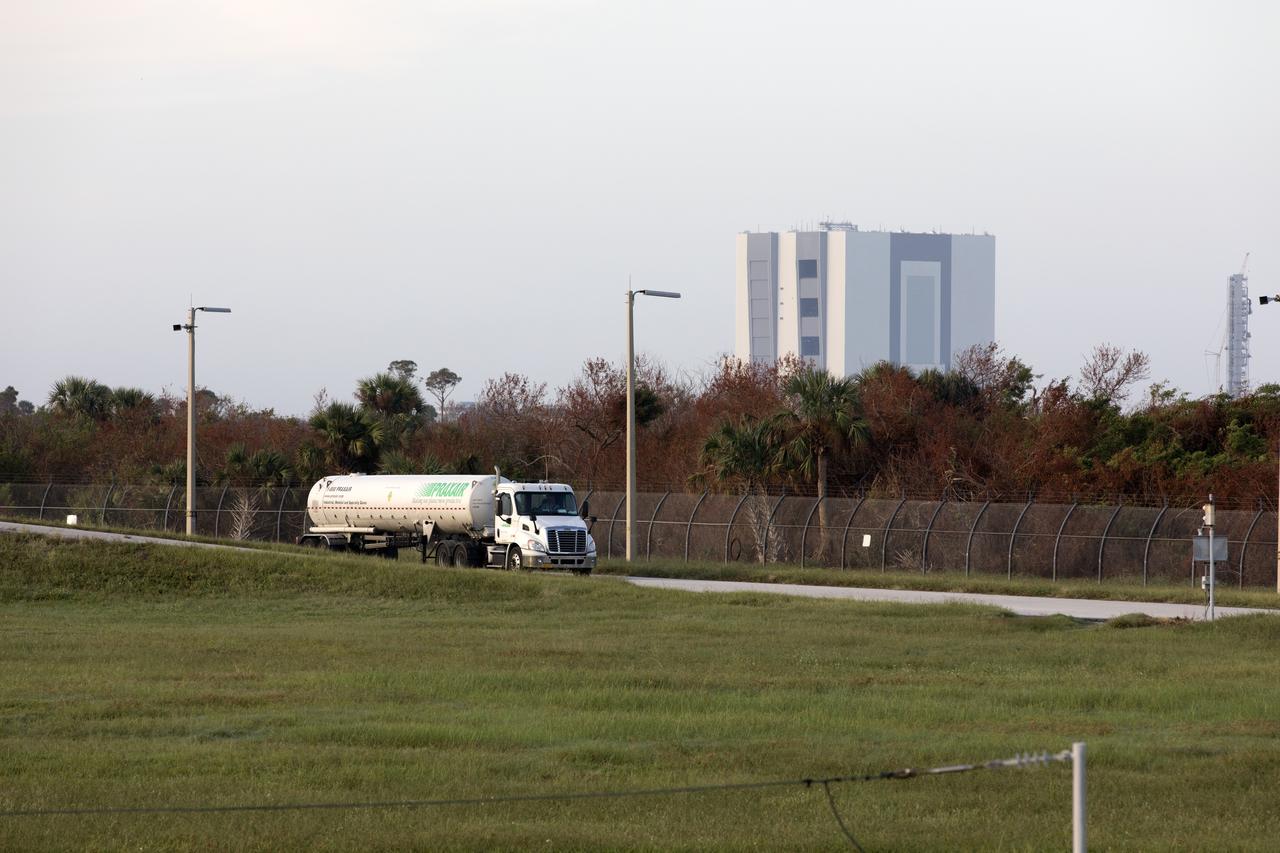
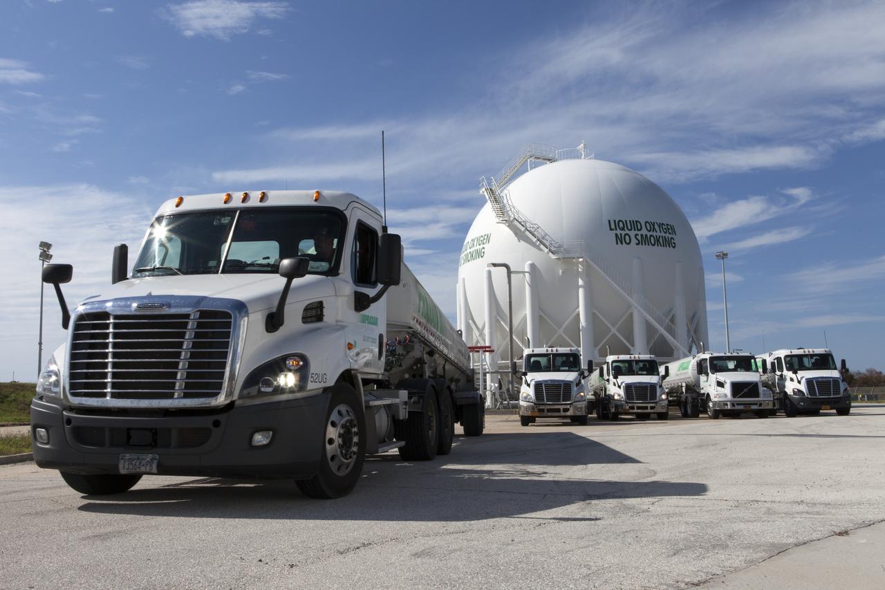
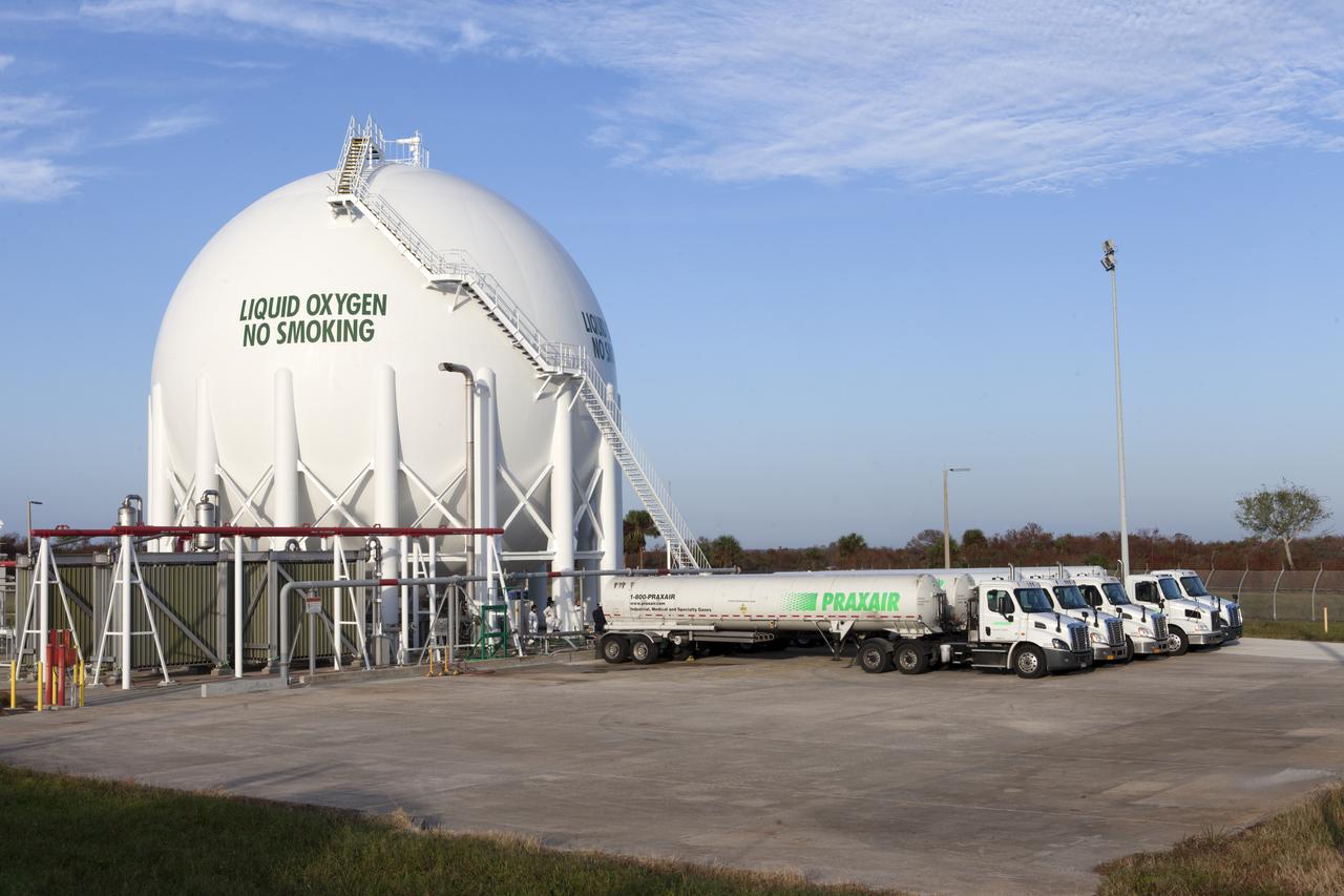
One of several Praxair trucks carrying its load of liquid oxygen, or LO2, is in route to Launch Pad 39B at NASA's Kennedy Space Center in Florida. The truck will offload LO2 slowly into a giant storage sphere located at the northwest corner of the pad to gradually chill it down from normal temperature to about negative 298 degrees Fahrenheit, during the first major integrated operation to prepare for the launch of the agency's Orion spacecraft atop the Space Launch System (SLS) rocket. The Ground Systems Development and Operations Program is overseeing upgrades and modifications to pad B to support the launch of the SLS and Orion spacecraft for Exploration Mission-1, deep space missions and NASA’s journey to Mars.

Several Praxair trucks carrying their loads of liquid oxygen, or LO2, arrive at Launch Pad 39B at NASA's Kennedy Space Center in Florida. The trucks will offload LO2 slowly into a giant storage sphere located at the northwest corner of the pad to gradually chill it down from normal temperature to about negative 298 degrees Fahrenheit, during the first major integrated operation to prepare for the launch of the agency's Orion spacecraft atop the Space Launch System (SLS) rocket. The Ground Systems Development and Operations Program is overseeing upgrades and modifications to pad B to support the launch of the SLS and Orion spacecraft for Exploration Mission-1, deep space missions and NASA’s journey to Mars.
James Fesmire, Ph.D., left, NASA lead engineer for the Cryogenics Testbed, and Adam Swanger, cryogenics engineer, hold a training session on Nov. 6, 2018, at the Cryogenics Laboratory at NASA's Kennedy Space Center in Florida. The training is for personnel who will be working to insulate pipes on the mobile launcher (ML). The ML is equipped with cryogenic fluid lines that will deliver hydrogen and oxygen to NASA's Space Launch System rocket. The lines must be kept well-insulated to maintain temperatures cold enough to keep fluids in a liquid state. In a new process, workers are learning how to pack spaces between pipes with aerogel granules in the same manner as they will on the ML.

Praxair trucks carrying their loads of liquid oxygen, or LO2, are on their way to Launch Pad 39B at NASA's Kennedy Space Center in Florida. The trucks will offload LO2 slowly into a giant storage sphere located at the northwest corner of the pad to gradually chill it down from normal temperature to about negative 298 degrees Fahrenheit, during the first major integrated operation to prepare for the launch of the agency's Orion spacecraft atop the Space Launch System (SLS) rocket. The Ground Systems Development and Operations Program is overseeing upgrades and modifications to pad B to support the launch of the SLS and Orion spacecraft for Exploration Mission-1, deep space missions and NASA’s journey to Mars.
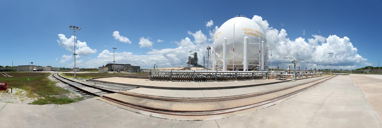
CAPE CANAVERAL, Fla. -- In the Launch Complex 39 area at NASA's Kennedy Space Center in Florida is a liquid hydrogen, or LH2, storage tank. This large ball-shaped, vacuum-jacketed tank is used to store cryogenic propellants for the space shuttle's orange external fuel tank. The LH2 tank is located at the northeast corner of Launch Pad 39A and stores 850,000 gallons of LH2 at a temperature of minus 423 degrees F. The shuttle's external tank is loaded with about 500,000 gallons of LH2 and liquid oxygen, or LOX, about six hours prior to launch in a process known as 'tanking.' Photo credit: NASA_Frankie Martin
Workers attend a cryogenic insulation training session on Nov. 6, 2018, at the Cryogenics Laboratory at NASA's Kennedy Space Center in Florida. The training is for personnel who will be working to insulate pipes on the mobile launcher (ML). The ML is equipped with cryogenic fluid lines that will deliver hydrogen and oxygen to NASA's Space Launch System rocket. The lines must be kept well-insulated to maintain temperatures cold enough to keep fluids in a liquid state. In a new process, workers are learning how to pack spaces between pipes with aerogel granules in the same manner as they will on the ML.
Several Praxair trucks begin to depart Launch Pad 39B at NASA's Kennedy Space Center in Florida, after offloading their loads of liquid oxygen, or LO2, one at a time into the giant storage sphere located at the northwest corner of the pad. The sphere was gradually chilled down from normal temperature to about negative 298 degrees Fahrenheit, during the first major integrated operation to prepare for the launch of the agency's Orion spacecraft atop the Space Launch System (SLS) rocket. The Ground Systems Development and Operations Program is overseeing upgrades and modifications to pad B to support the launch of the SLS and Orion spacecraft for Exploration Mission-1, deep space missions and NASA’s journey to Mars.
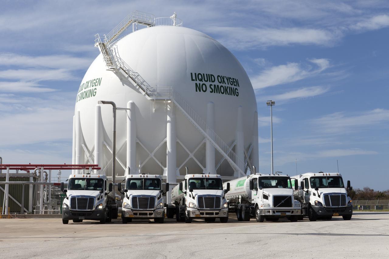
Several Praxair trucks carrying their loads of liquid oxygen, or LO2, have arrived at Launch Pad 39B at NASA's Kennedy Space Center in Florida. The trucks will begin to offload the LO2 one at a time into the giant storage sphere located at the northwest corner of the pad. The sphere will gradually be chilled down from normal temperature to about negative 298 degrees Fahrenheit, during the first major integrated operation to prepare for the launch of the agency's Orion spacecraft atop the Space Launch System (SLS) rocket. The Ground Systems Development and Operations Program is overseeing upgrades and modifications to pad B to support the launch of the SLS and Orion spacecraft for Exploration Mission-1, deep space missions and NASA’s journey to Mars.
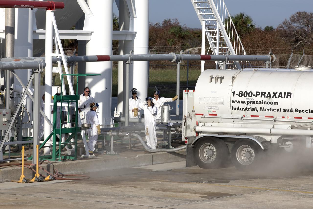
Mist or vapor is visible as a Praxair truck slowly transfers its load of liquid oxygen, or LO2, into a giant storage sphere at the northwest corner of Launch Pad 39B at NASA's Kennedy Space Center in Florida. The sphere will gradually be chilled down from normal temperature to about negative 298 degrees Fahrenheit, during the first major integrated operation to prepare for the launch of the agency's Orion spacecraft atop the Space Launch System (SLS) rocket. The Ground Systems Development and Operations Program is overseeing upgrades and modifications to pad B to support the launch of the SLS and Orion spacecraft for Exploration Mission-1, deep space missions and NASA’s journey to Mars.
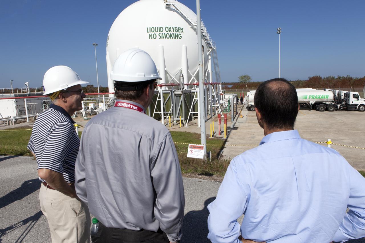
Engineers watch as several Praxair trucks carrying their loads of liquid oxygen, or LO2, arrive at Launch Pad 39B at NASA's Kennedy Space Center in Florida. The trucks will offload the LO2 one at a time into the giant storage sphere located at the northwest corner of the pad. The sphere will gradually be chilled down from normal temperature to about negative 298 degrees Fahrenheit, during the first major integrated operation to prepare for the launch of the agency's Orion spacecraft atop the Space Launch System (SLS) rocket. The Ground Systems Development and Operations Program is overseeing upgrades and modifications to pad B to support the launch of the SLS and Orion spacecraft for Exploration Mission-1, deep space missions and NASA’s journey to Mars.

James Fesmire, Ph.D., left, NASA lead engineer for the Cryogenics Testbed, holds a training session on Nov. 6, 2018, at the Cryogenics Laboratory at NASA's Kennedy Space Center in Florida. The training is for personnel who will be working to insulate pipes on the mobile launcher (ML). The ML is equipped with cryogenic fluid lines that will deliver hydrogen and oxygen to NASA's Space Launch System rocket. The lines must be kept well-insulated to maintain temperatures cold enough to keep fluids in a liquid state. In a new process, workers are learning how to pack spaces between pipes with aerogel granules in the same manner as they will on the ML.
Workers attend a cryogenic insulation training session on Nov. 6, 2018, at the Cryogenics Laboratory at NASA's Kennedy Space Center in Florida. The training is for personnel who will be working to insulate pipes on the mobile launcher (ML). The ML is equipped with cryogenic fluid lines that will deliver hydrogen and oxygen to NASA's Space Launch System rocket. The lines must be kept well-insulated to maintain temperatures cold enough to keep fluids in a liquid state. In a new process, workers are learning how to pack spaces between pipes with aerogel granules in the same manner as they will on the ML.
Workers attend a cryogenic insulation training session on Nov. 6, 2018, at the Cryogenics Laboratory at NASA's Kennedy Space Center in Florida. The training is for personnel who will be working to insulate pipes on the mobile launcher (ML). The ML is equipped with cryogenic fluid lines that will deliver hydrogen and oxygen to NASA's Space Launch System rocket. The lines must be kept well-insulated to maintain temperatures cold enough to keep fluids in a liquid state. In a new process, workers are learning how to pack spaces between pipes with aerogel granules in the same manner as they will on the ML.
Several Praxair trucks carrying their loads of liquid oxygen, or LO2, have arrived at Launch Pad 39B at NASA's Kennedy Space Center in Florida. The trucks will offload LO2 slowly into a giant storage sphere located at the northwest corner of the pad to gradually chill it down from normal temperature to about negative 298 degrees Fahrenheit, during the first major integrated operation to prepare for the launch of the agency's Orion spacecraft atop the Space Launch System (SLS) rocket. The Ground Systems Development and Operations Program is overseeing upgrades and modifications to pad B to support the launch of the SLS and Orion spacecraft for Exploration Mission-1, deep space missions and NASA’s journey to Mars.

Workers practice during a cryogenic insulation training session on Nov. 6, 2018, at the Cryogenics Laboratory at NASA's Kennedy Space Center in Florida. The training is for personnel who will be working to insulate pipes on the mobile launcher (ML). The ML is equipped with cryogenic fluid lines that will deliver hydrogen and oxygen to NASA's Space Launch System rocket. The lines must be kept well-insulated to maintain temperatures cold enough to keep fluids in a liquid state. In a new process, workers are learning how to pack spaces between pipes with aerogel granules in the same manner as they will on the ML.
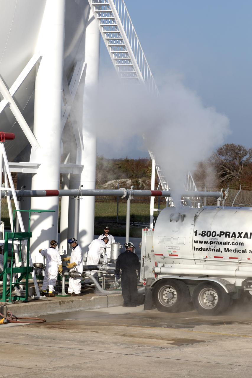
A large plume of mist or vapor is visible as a Praxair truck slowly transfers its load of liquid oxygen, or LO2, into a giant storage sphere at the northwest corner of Launch Pad 39B at NASA's Kennedy Space Center in Florida. The sphere will gradually be chilled down from normal temperature to about negative 298 degrees Fahrenheit, during the first major integrated operation to prepare for the launch of the agency's Orion spacecraft atop the Space Launch System (SLS) rocket. The Ground Systems Development and Operations Program is overseeing upgrades and modifications to pad B to support the launch of the SLS and Orion spacecraft for Exploration Mission-1, deep space missions and NASA’s journey to Mars.
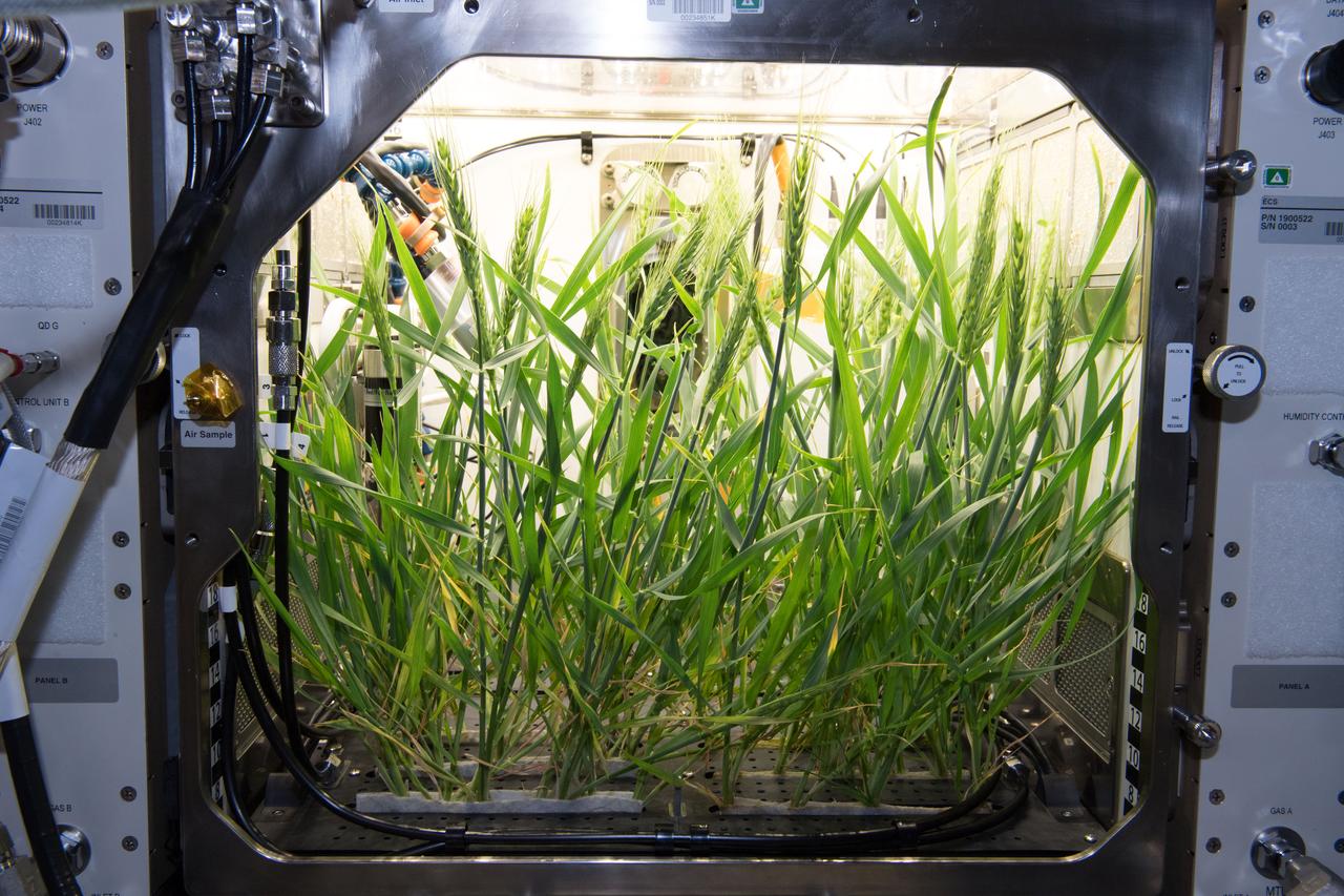
The first growth test of crops in the Advanced Plant Habitat aboard the International Space Station yielded great results. Arabidopsis seeds – small flowering plants related to cabbage and mustard – grew for about six weeks and the dwarf wheat for five weeks. The APH is now ready to support large plant testing on ISS. APH is a fully enclosed, closed-loop system with an environmentally controlled growth chamber. It uses red, blue and green LED lights, and broad spectrum white LED lights. The system's more than 180 sensors will relay real-time information, including temperature, oxygen content and moisture levels back to the team at Kennedy Space Center.
Tests begun at Stennis Space Center's E Complex Sept. 13 evaluated a liquid oxygen lead for engine start performance, part of the A-3 Test Facility Subscale Diffuser Risk Mitigation Project at SSC's E-3 Test Facility. Phase 1 of the subscale diffuser project, completed Sept. 24, was a series of 18 hot-fire tests using a 1,000-pound liquid oxygen and gaseous hydrogen thruster to verify maximum duration and repeatability for steam generation supporting the A-3 Test Stand project. The thruster is a stand-in for NASA's developing J-2X engine, to validate a 6 percent scale version of A-3's exhaust diffuser. Testing the J-2X at altitude conditions requires an enormous diffuser. Engineers will generate nearly 4,600 pounds per second of steam to reduce pressure inside A-3's test cell to simulate altitude conditions. A-3's exhaust diffuser has to be able to withstand regulated pressure, temperatures and the safe discharge of the steam produced during those tests. Before the real thing is built, engineers hope to work out any issues on the miniature version. Phase 2 testing is scheduled to begin this month.
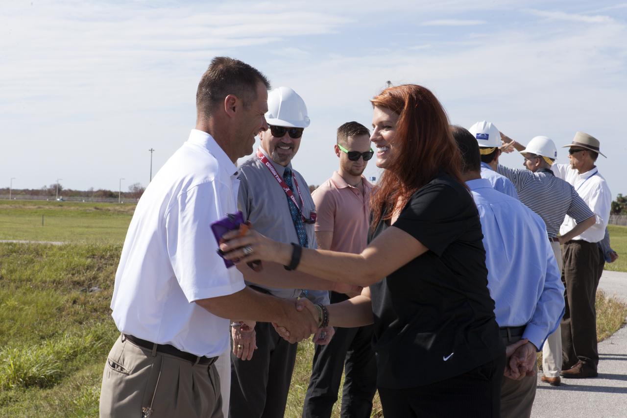
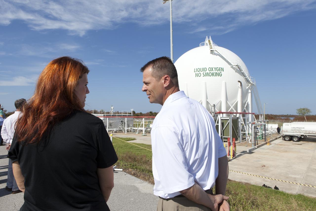
NASA Launch Director Charlie Blackwell-Thompson, at right, greets engineers and technicians at Launch Pad 39B at the agency's Kennedy Space Center in Florida. Blackwell-Thompson will observe the first major tanking operation of liquid oxygen, or LO2, into the giant storage sphere at the northwest corner of the pad to prepare for the launch of the agency's Orion spacecraft atop the Space Launch System (SLS) rocket. During the operation, several Praxair trucks will slowly offload LO2 to gradually chill down the sphere from normal temperature to about negative 298 degrees Fahrenheit. The Ground Systems Development and Operations Program is overseeing upgrades and modifications to pad B to support the launch of the SLS and Orion spacecraft for Exploration Mission-1, deep space missions and NASA’s journey to Mars.
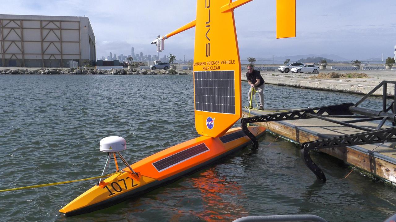
As part of NASA's Sub-Mesoscale Ocean Dynamics Experiment (S-MODE) field campaign, several Saildrones like the one pictured here were launched from San Francisco Bay. The Saildrones were part of a fleet of autonomous marine research vessels designed to measure a vast array of factors such as ocean currents, wind speed and direction, air and water temperature, salinity, dissolved oxygen, and chlorophyll content. S-MODE is a NASA Earth mission to use newly developed in-situ and remote-sensing techniques to look at small-scale ocean whirlpools, eddies, and currents. The observations could help scientists better understand how these dynamics drive the give-and-take of material and energy between the ocean and atmosphere and, ultimately, help shape Earth's climate. More information about S-MODE is at https://espo.nasa.gov/s-mode/content/S-MODE https://photojournal.jpl.nasa.gov/catalog/PIA25523
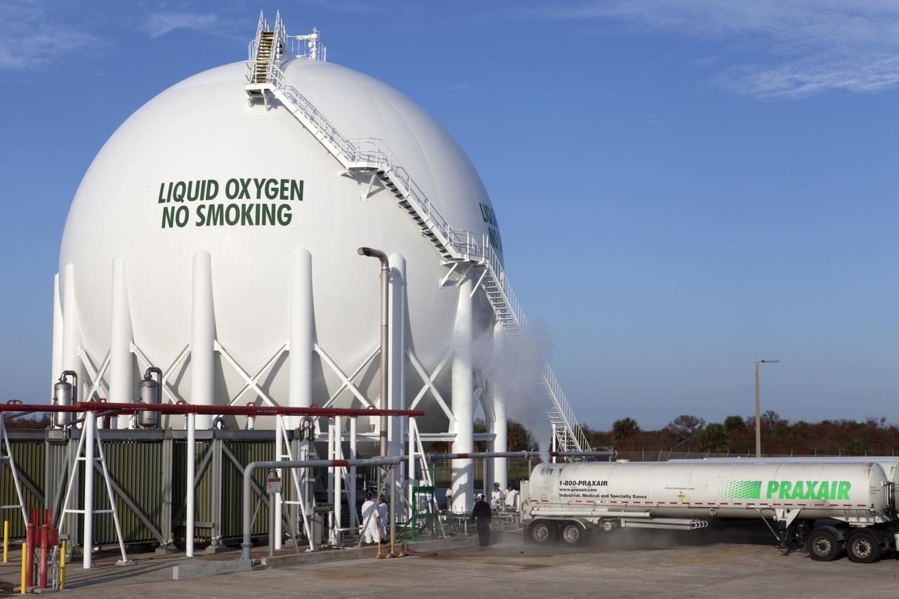
Several Praxair trucks carrying their loads of liquid oxygen, or LO2, have arrived at Launch Pad 39B at NASA's Kennedy Space Center in Florida. A mist is visible as LO2 is offloaded from one of the trucks into the giant storage sphere located at the northwest corner of the pad has begun. The sphere will gradually be chilled down from normal temperature to about negative 298 degrees Fahrenheit, during the first major integrated operation to prepare for the launch of the agency's Orion spacecraft atop the Space Launch System (SLS) rocket. The Ground Systems Development and Operations Program is overseeing upgrades and modifications to pad B to support the launch of the SLS and Orion spacecraft for Exploration Mission-1, deep space missions and NASA’s journey to Mars.
NASA Launch Director Charlie Blackwell-Thompson, at left, arrives at Launch Pad 39B at NASA's Kennedy Space Center in Florida, to observe the first major tanking operation of liquid oxygen, or LO2, into the giant storage sphere at the northwest corner of the pad to prepare for the launch of the agency's Orion spacecraft atop the Space Launch System (SLS) rocket. During the operation, several Praxair trucks will slowly offload LO2 to gradually chill down the sphere from normal temperature to about negative 298 degrees Fahrenheit. The Ground Systems Development and Operations Program is overseeing upgrades and modifications to pad B to support the launch of the SLS and Orion spacecraft for Exploration Mission-1, deep space missions and NASA’s journey to Mars.
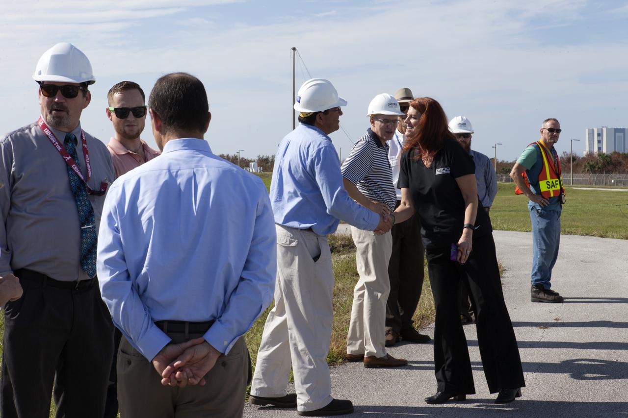
NASA Launch Director Charlie Blackwell-Thompson, at right, greets engineers and technicians at Launch Pad 39B at the agency's Kennedy Space Center in Florida. Blackwell-Thompson will observe the first major tanking operation of liquid oxygen, or LO2, into the giant storage sphere at the northwest corner of the pad to prepare for the launch of the agency's Orion spacecraft atop the Space Launch System (SLS) rocket. During the operation, several Praxair trucks will slowly offload LO2 to gradually chill down the sphere from normal temperature to about negative 298 degrees Fahrenheit. The Ground Systems Development and Operations Program is overseeing upgrades and modifications to pad B to support the launch of the SLS and Orion spacecraft for Exploration Mission-1, deep space missions and NASA’s journey to Mars.
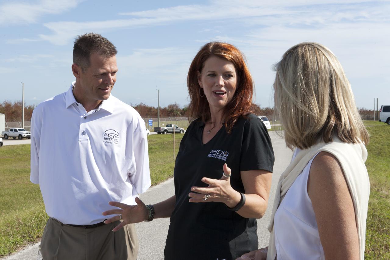
NASA Launch Director Charlie Blackwell-Thompson, center, talks to engineers at Launch Pad 39B at the agency's Kennedy Space Center in Florida. Blackwell-Thompson will observe the first major tanking operation of liquid oxygen, or LO2, into the giant storage sphere at the northwest corner of the pad to prepare for the launch of the agency's Orion spacecraft atop the Space Launch System (SLS) rocket. During the operation, several Praxair trucks will slowly offload LO2 to gradually chill down the sphere from normal temperature to about negative 298 degrees Fahrenheit. The Ground Systems Development and Operations Program is overseeing upgrades and modifications to pad B to support the launch of the SLS and Orion spacecraft for Exploration Mission-1, deep space missions and NASA’s journey to Mars.
CAPE CANAVERAL, Fla. -- Space shuttle Discovery's external fuel tank is being filled with more than 535,000 gallons of super-cold liquid hydrogen and liquid oxygen during a tanking test on Launch Pad 39A at NASA's Kennedy Space Center in Florida. Engineers are closely monitoring what happens to 21-foot long, U-shaped aluminum brackets, called stringers, located at the tank's intertank region, as well as the newly replaced ground umbilical carrier plate (GUCP). Data from 89 sensors will be evaluated after the tank returns to ambient temperature. In order to perform additional analysis on the tank, Discovery will be rolled back to the Vehicle Assembly Building, a move that is planned for next week. Discovery's first launch attempt for STS-133 was scrubbed in early November due to a hydrogen gas leak at GUCP. The next launch opportunity is no earlier than Feb. 3, 2011. For more information on STS-133, visit www.nasa.gov/mission_pages/shuttle/shuttlemissions/sts133/. Photo credit: NASA/Frank Michaux
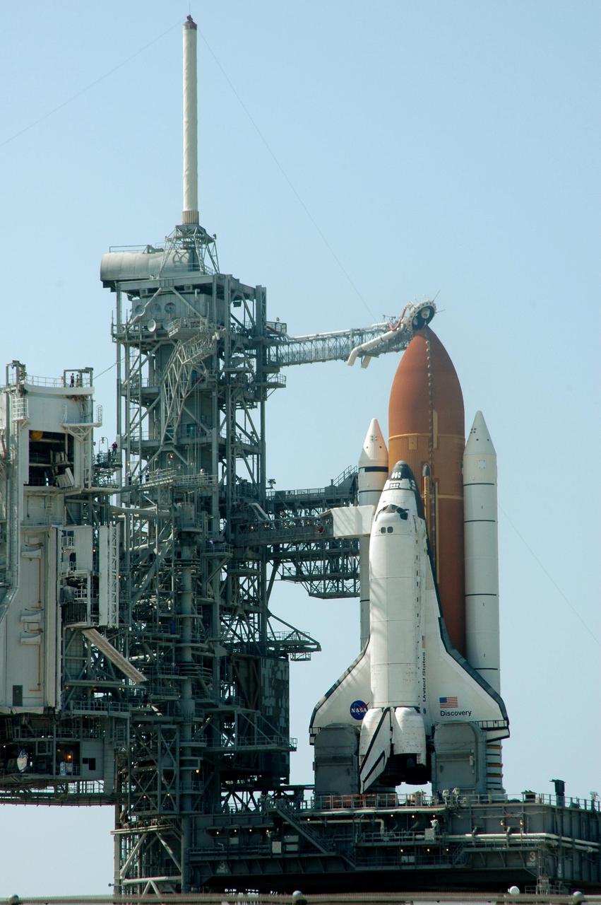
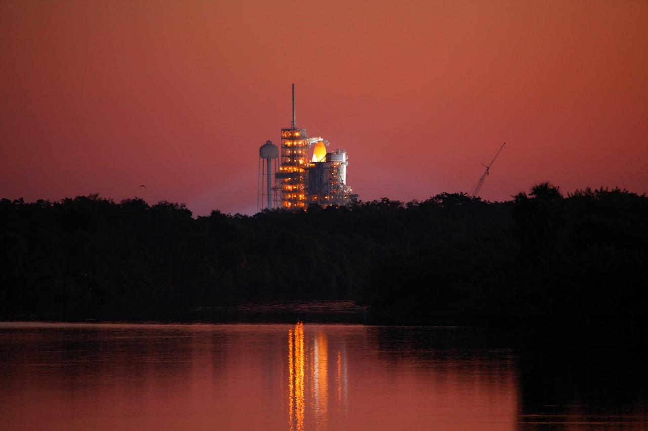
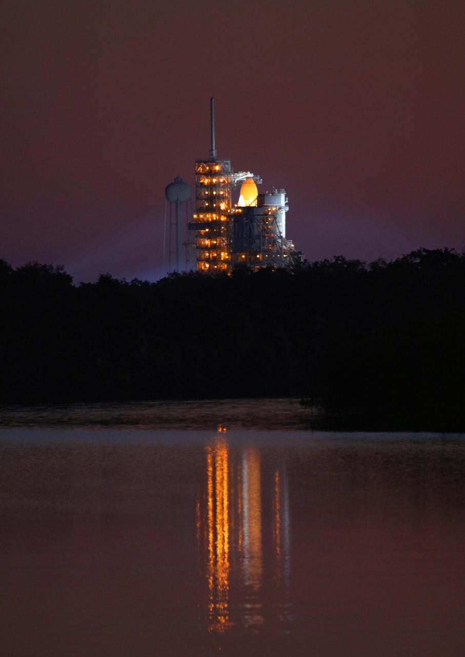
KENNEDY SPACE CENTER, FLA. - Space Shuttle Discovery in full launch configuration is revealed after the Rotating Service Structure (RSS) is rotated back at Launch Pad 39B at NASA Kennedy Space Center. The gaseous oxygen vent arm (beanie cap) has been extended to the top of the External Tank. Rollback of the RSS is a major preflight milestone, typically occurring during the T-11-hour hold on L-1 (the day before launch). Discovery is scheduled to lift off on the historic Return to Flight mission STS-114 at 10:39 a.m. EDT July 26 with a crew of seven. On the mission to the International Space Station the crew will perform inspections on orbit for the first time of all of the Reinforced Carbon-Carbon (RCC) panels on the leading edge of the wings and the Thermal Protection System tiles using the new Canadian-built Orbiter Boom Sensor System and the data from 176 impact and temperature sensors. Mission Specialists will also practice repair techniques on RCC and tile samples during a spacewalk in the payload bay. During two additional spacewalks, the crew will install the External Stowage Platform-2, equipped with spare part assemblies, and a replacement Control Moment Gyroscope contained in the Lightweight Multi-Purpose Experiment Support Structure.

STS087-716-080 (19 November – 5 December 1997) --- Featured in this view is Mount Everest. It is called “Sagarmatha” in Nepal and “Qomolangma Feng” Qomolangma in China (both names meaning “Goddess Mother of the World”), but is known to the western world as Mount Everest. At an altitude of 29,028 feet (8,848 meters) the summit of tallest mountain on Earth (above sea level) reaches two-thirds of the way through the atmosphere. Situated on the border between Nepal and China (27°59’N, 86°56’E), Mount Everest with its low oxygen levels, powerful winds, and extremely cold temperatures has captured the imagination of adventuresome men and women. Sir Edmund Hillary and Tenzing Norgay were the first persons to surmount Mount Everest in 1953. While climbing Everest can be challenging, it can also be tragic. On May 10, 1996, after reaching the summit and descending to camp, several climbers were trapped by a severe and sudden storm. A total of eight people died, making this day the deadliest single tragedy in the history of Mount Everest. This picture is one of the 70mm Earth observations visuals used by the crew at its post flight presentation events.
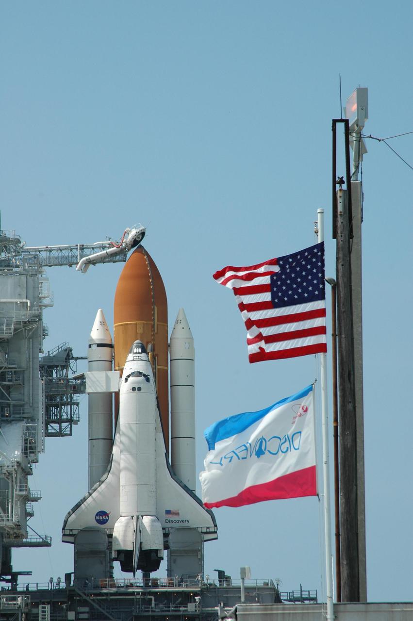
KENNEDY SPACE CENTER, FLA. - Flags are flying on Launch Pad 39B at NASA Kennedy Space Center as Space Shuttle Discovery is ready on the pad for launch after rollback of the Rotating Service Structure. Visible above the External Tank is the gaseous oxygen vent arm (beanie cap). Rollback of the RSS is a major preflight milestone, typically occurring during the T-11-hour hold on L-1 (the day before launch). Discovery is scheduled to lift off on the historic Return to Flight mission STS-114 at 10:39 a.m. EDT July 26 with a crew of seven. On the mission to the International Space Station the crew will perform inspections on orbit for the first time of all of the Reinforced Carbon-Carbon (RCC) panels on the leading edge of the wings and the Thermal Protection System tiles using the new Canadian-built Orbiter Boom Sensor System and the data from 176 impact and temperature sensors. Mission Specialists will also practice repair techniques on RCC and tile samples during a spacewalk in the payload bay. During two additional spacewalks, the crew will install the External Stowage Platform-2, equipped with spare part assemblies, and a replacement Control Moment Gyroscope contained in the Lightweight Multi-Purpose Experiment Support Structure.

In the bunker at Launch Pad 39B, STS-103 Mission Specialist Jean-François Clervoy of France, who is with the European Space Agency (ESA), tries on an oxygen mask during Terminal Countdown Demonstration Test (TCDT) activities. The TCDT provides the crew with emergency egress training, opportunities to inspect their mission payloads in the orbiter's payload bay, and simulated countdown exercises. Other crew members taking part are Commander Curtis L. Brown Jr. and Mission Specialists Steven L. Smith, C. Michael Foale (Ph.D.), John M. Grunsfeld (Ph.D.), plus Claude Nicollier of Switzerland, who is also with ESA. STS-103 is a "call-up" mission due to the need to replace and repair portions of the Hubble Space Telescope, including the gyroscopes that allow the telescope to point at stars, galaxies and planets. The STS-103 crew will be replacing a Fine Guidance Sensor, an older computer with a new enhanced model, an older data tape recorder with a solid-state digital recorder, a failed spare transmitter with a new one, and degraded insulation on the telescope with new thermal insulation. The crew will also install a Battery Voltage/Temperature Improvement Kit to protect the spacecraft batteries from overcharging and overheating when the telescope goes into a safe mode. Four EVA's are planned to make the necessary repairs and replacements on the telescope. The mission is targeted for launch Dec. 6 at 2:37 a.m. EST
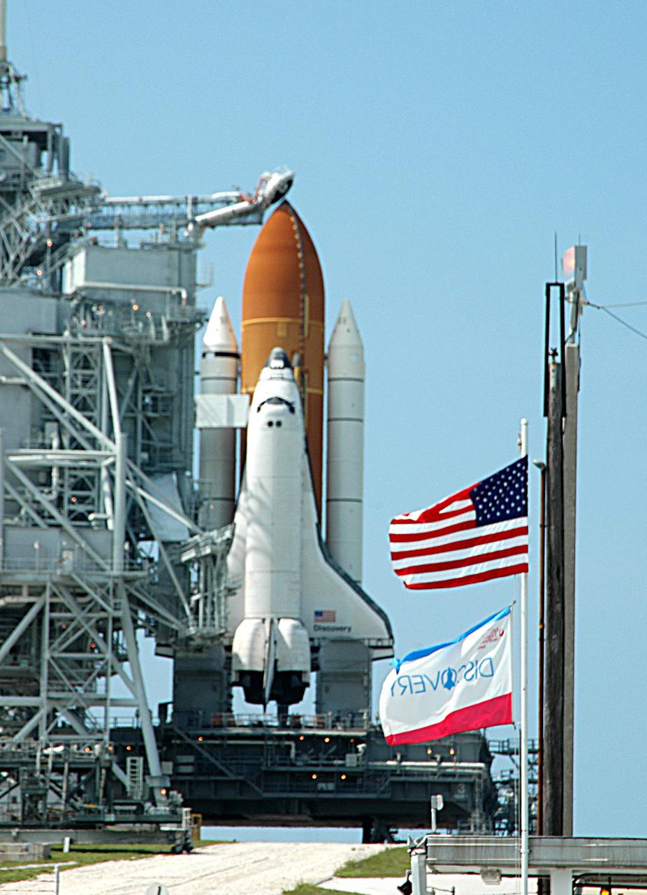
KENNEDY SPACE CENTER, FLA. - Flags are flying on Launch Pad 39B at NASA Kennedy Space Center as Space Shuttle Discovery is ready on the pad for launch after rollback of the Rotating Service Structure. Visible above the External Tank is the gaseous oxygen vent arm (beanie cap). Rollback of the RSS is a major preflight milestone, typically occurring during the T-11-hour hold on L-1 (the day before launch). Discovery is scheduled to lift off on the historic Return to Flight mission STS-114 at 10:39 a.m. EDT July 26 with a crew of seven. On the mission to the International Space Station the crew will perform inspections on orbit for the first time of all of the Reinforced Carbon-Carbon (RCC) panels on the leading edge of the wings and the Thermal Protection System tiles using the new Canadian-built Orbiter Boom Sensor System and the data from 176 impact and temperature sensors. Mission Specialists will also practice repair techniques on RCC and tile samples during a spacewalk in the payload bay. During two additional spacewalks, the crew will install the External Stowage Platform-2, equipped with spare part assemblies, and a replacement Control Moment Gyroscope contained in the Lightweight Multi-Purpose Experiment Support Structure.
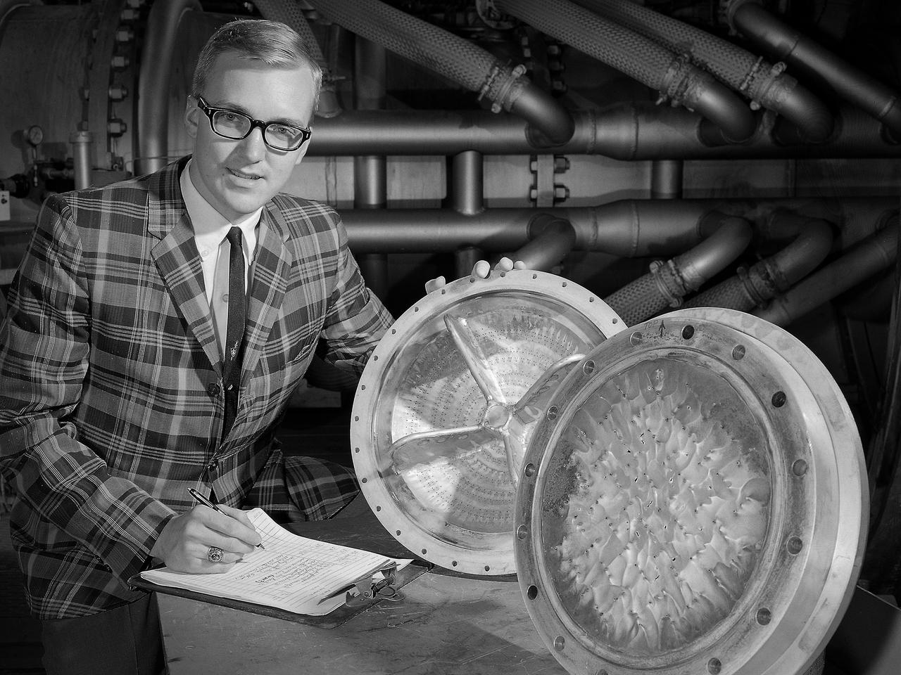
Dan Sokolowski worked as an engineering coop student at the National Aeronautics and Space Administration (NASA) Lewis Research Center from 1962 to 1966 while earning his Mechanical Engineering degree from Purdue. At the time of this photograph Sokolowski had just been hired as a permanent NASA employee in the Chemical Rocket Evaluation Branch of the Chemical Rocket Division. He had also just won a regional American Institute of Aeronautics and Astronautics competition for his paper on high and low-frequency combustion instability. The resolution of the low-frequency combustion instability, or chugging, in liquid hydrogen rocket systems was one of Lewis’ more significant feats of the early 1960s. In most rocket engine combustion chambers, the pressure, temperature, and flows are in constant flux. The engine is considered to be operating normally if the fluctuations remain random and within certain limits. Lewis researchers used high-speed photography to study and define Pratt and Whitney’s RL-10’s combustion instability by throttling the engine under the simulated flight conditions. They found that the injection of a small stream of helium gas into the liquid-oxygen tank immediately stabilized the system. Sokolowski’s later work focused on combustion in airbreathing engines. In 1983 was named Manager of a multidisciplinary program aimed at improving durability of combustor and turbine components. After 39 years Sokolowski retired from NASA in September 2002.
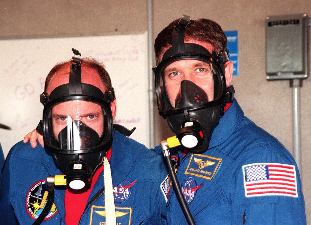
In the bunker at Launch Pad 39B, STS-103 Pilot Scott J. Kelly (left) and Mission Specialist John M. Grunsfeld (Ph.D.) (right) try on oxygen masks during Terminal Countdown Demonstration Test (TCDT) activities. The TCDT provides the crew with emergency egress training, opportunities to inspect their mission payloads in the orbiter's payload bay, and simulated countdown exercises. Other crew members taking part are Commander Curtis L. Brown Jr. and Mission Specialists Steven L. Smith, C. Michael Foale (Ph.D.), and Jean-François Clervoy of France and Claude Nicollier of Switzerland, who are with the European Space Agency. STS-103 is a "call-up" mission due to the need to replace and repair portions of the Hubble Space Telescope, including the gyroscopes that allow the telescope to point at stars, galaxies and planets. The STS-103 crew will be replacing a Fine Guidance Sensor, an older computer with a new enhanced model, an older data tape recorder with a solid-state digital recorder, a failed spare transmitter with a new one, and degraded insulation on the telescope with new thermal insulation. The crew will also install a Battery Voltage/Temperature Improvement Kit to protect the spacecraft batteries from overcharging and overheating when the telescope goes into a safe mode. Four EVA's are planned to make the necessary repairs and replacements on the telescope. The mission is targeted for launch Dec. 6 at 2:37 a.m. EST
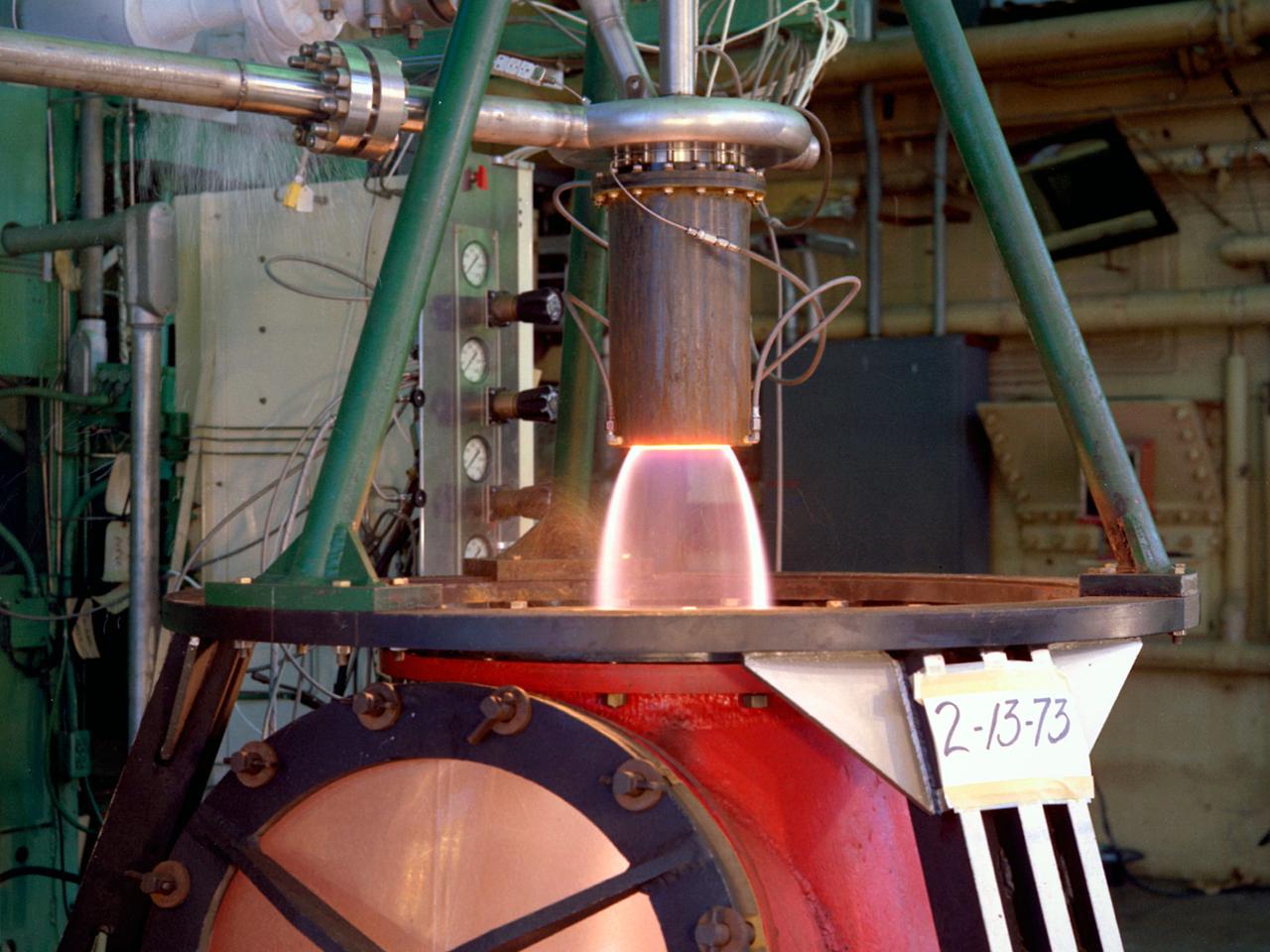
The thrust stand in the Rocket Engine Test Facility at the National Aeronautics and Space Administration (NASA) Lewis Research Center in Cleveland, Ohio. The Rocket Engine Test Facility was constructed in the mid-1950s to expand upon the smaller test cells built a decade before at the Rocket Laboratory. The $2.5-million Rocket Engine Test Facility could test larger hydrogen-fluorine and hydrogen-oxygen rocket thrust chambers with thrust levels up to 20,000 pounds. Test Stand A, seen in this photograph, was designed to fire vertically mounted rocket engines downward. The exhaust passed through an exhaust gas scrubber and muffler before being vented into the atmosphere. Lewis researchers in the early 1970s used the Rocket Engine Test Facility to perform basic research that could be utilized by designers of the Space Shuttle Main Engines. A new electronic ignition system and timer were installed at the facility for these tests. Lewis researchers demonstrated the benefits of ceramic thermal coatings for the engine’s thrust chamber and determined the optimal composite material for the coatings. They compared the thermal-coated thrust chamber to traditional unlined high-temperature thrust chambers. There were more than 17,000 different configurations tested on this stand between 1973 and 1976. The Rocket Engine Test Facility was later designated a National Historic Landmark for its role in the development of liquid hydrogen as a propellant.
CAPE CANAVERAL, Fla. -- Space shuttle Discovery's external fuel tank is being filled with more than 535,000 gallons of super-cold liquid hydrogen and liquid oxygen during a tanking test on Launch Pad 39A at NASA's Kennedy Space Center in Florida. Engineers are closely monitoring what happens to 21-foot long, U-shaped aluminum brackets, called stringers, located at the tank's intertank region, as well as the newly replaced ground umbilical carrier plate (GUCP). Data from 89 sensors will be evaluated after the tank returns to ambient temperature. In order to perform additional analysis on the tank, Discovery will be rolled back to the Vehicle Assembly Building, a move that is planned for next week. Discovery's first launch attempt for STS-133 was scrubbed in early November due to a hydrogen gas leak at GUCP. The next launch opportunity is no earlier than Feb. 3, 2011. For more information on STS-133, visit www.nasa.gov/mission_pages/shuttle/shuttlemissions/sts133/. Photo credit: NASA/Frank Michaux
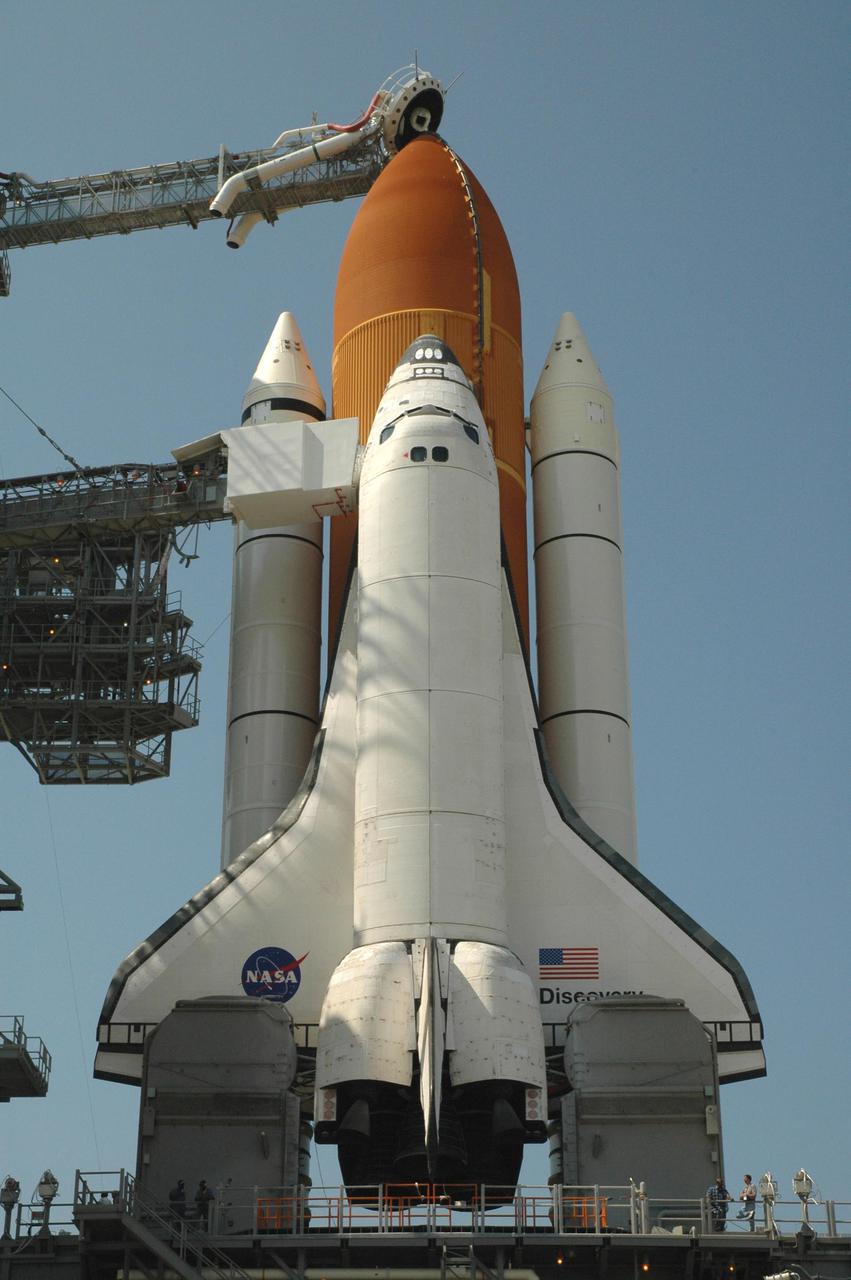
KENNEDY SPACE CENTER, FLA. - Space Shuttle Discovery in full launch configuration is revealed after the Rotating Service Structure (RSS) is rotated back at Launch Pad 39B at NASA Kennedy Space Center. The gaseous oxygen vent arm (beanie cap) has been extended to the top of the External Tank and the orbiter access arm is extended to Discovery’s hatch. Rollback of the RSS is a major preflight milestone, typically occurring during the T-11-hour hold on L-1 (the day before launch). Discovery is scheduled to lift off on the historic Return to Flight mission STS-114 at 10:39 a.m. EDT July 26 with a crew of seven. On the mission to the International Space Station the crew will perform inspections on orbit for the first time of all of the Reinforced Carbon-Carbon (RCC) panels on the leading edge of the wings and the Thermal Protection System tiles using the new Canadian-built Orbiter Boom Sensor System and the data from 176 impact and temperature sensors. Mission Specialists will also practice repair techniques on RCC and tile samples during a spacewalk in the payload bay. During two additional spacewalks, the crew will install the External Stowage Platform-2, equipped with spare part assemblies, and a replacement Control Moment Gyroscope contained in the Lightweight Multi-Purpose Experiment Support Structure.

This illustration shows three possible interiors of the seven rocky exoplanets in the TRAPPIST-1 system, based on precision measurements of the planet densities. Overall the TRAPPIST-1 worlds have remarkably similar densities, which suggests they may share the same ratio of common planet-forming elements. The planet densities are slightly lower than those of Earth or Venus, which could mean they contain fractionally less iron (a highly dense material) or more low-density materials, such as water or oxygen. In the first model (left), the interior of the planet is composed of rock mixed with iron bound to oxygen. There is no solid iron core, which is the case with Earth and the other rocky planets in our own solar system. The second model shows an overall composition similar to Earth's, in which the densest materials have settled to the center of the planet, forming an iron-rich core proportionally smaller than Earth's core. A variation is shown in the third panel, where a larger, denser core could be balanced by an extensive low-density ocean on the planet's surface. However, this scenario can be applied only to the outer four planets in the TRAPPIST-1 system. On the inner three planets, any oceans would vaporize due to the higher temperatures near their star, and a different composition model is required. Since all seven planets have remarkably similar densities, it is more likely that all the planets share a similar bulk composition, making this fourth scenario unlikely but not impossible. The high-precision mass and diameter measurements of the exoplanets in the TRAPPIST-1 system have allowed astronomers to calculate the overall densities of these worlds with an unprecedented degree of accuracy in exoplanet research. Density measurements are a critical first step in determining the composition and structure of exoplanets, but they must be interpreted through the lens of scientific models of planetary structure. https://photojournal.jpl.nasa.gov/catalog/PIA24372
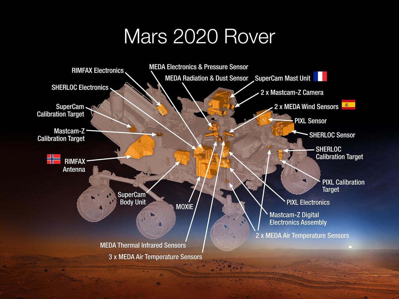
This 2015 diagram shows components of the investigations payload for NASA's Mars 2020 rover mission. Mars 2020 will re-use the basic engineering of NASA's Mars Science Laboratory to send a different rover to Mars, with new objectives and instruments, launching in 2020. The rover will carry seven instruments to conduct its science and exploration technology investigations. They are: Mastcam-Z, an advanced camera system with panoramic and stereoscopic imaging capability and the ability to zoom. The instrument also will determine mineralogy of the Martian surface and assist with rover operations. The principal investigator is James Bell, Arizona State University in Tempe. SuperCam, an instrument that can provide imaging, chemical composition analysis, and mineralogy. The instrument will also be able to detect the presence of organic compounds in rocks and regolith from a distance. The principal investigator is Roger Wiens, Los Alamos National Laboratory, Los Alamos, New Mexico. This instrument also has a significant contribution from the Centre National d'Etudes Spatiales, Institut de Recherche en Astrophysique et Planétologie (CNES/IRAP) France. Planetary Instrument for X-ray Lithochemistry (PIXL), an X-ray fluorescence spectrometer that will also contain an imager with high resolution to determine the fine-scale elemental composition of Martian surface materials. PIXL will provide capabilities that permit more detailed detection and analysis of chemical elements than ever before. The principal investigator is Abigail Allwood, NASA's Jet Propulsion Laboratory, Pasadena, California. Scanning Habitable Environments with Raman & Luminescence for Organics and Chemicals (SHERLOC), a spectrometer that will provide fine-scale imaging and uses an ultraviolet (UV) laser to determine fine-scale mineralogy and detect organic compounds. SHERLOC will be the first UV Raman spectrometer to fly to the surface of Mars and will provide complementary measurements with other instruments in the payload. SHERLOC includes a high-resolution color camera for microscopic imaging of Mars' surface. The principal investigator is Luther Beegle, JPL. The Mars Oxygen ISRU Experiment (MOXIE), an exploration technology investigation that will produce oxygen from Martian atmospheric carbon dioxide. The principal investigator is Michael Hecht, Massachusetts Institute of Technology, Cambridge, Massachusetts. Mars Environmental Dynamics Analyzer (MEDA), a set of sensors that will provide measurements of temperature, wind speed and direction, pressure, relative humidity and dust size and shape. The principal investigator is Jose Rodriguez-Manfredi, Centro de Astrobiologia, Instituto Nacional de Tecnica Aeroespacial, Spain. The Radar Imager for Mars' Subsurface Experiment (RIMFAX), a ground-penetrating radar that will provide centimeter-scale resolution of the geologic structure of the subsurface. The principal investigator is Svein-Erik Hamran, the Norwegian Defence Research Establishment, Norway. http://photojournal.jpl.nasa.gov/catalog/PIA19672
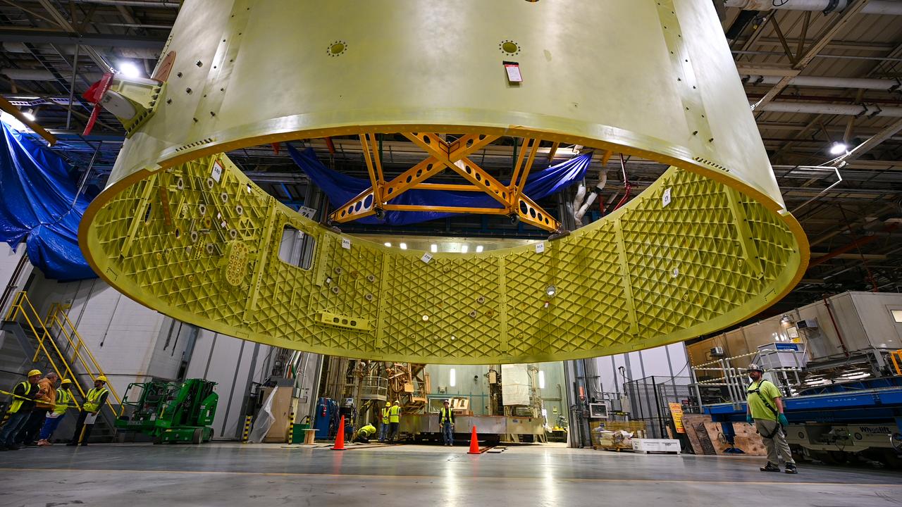
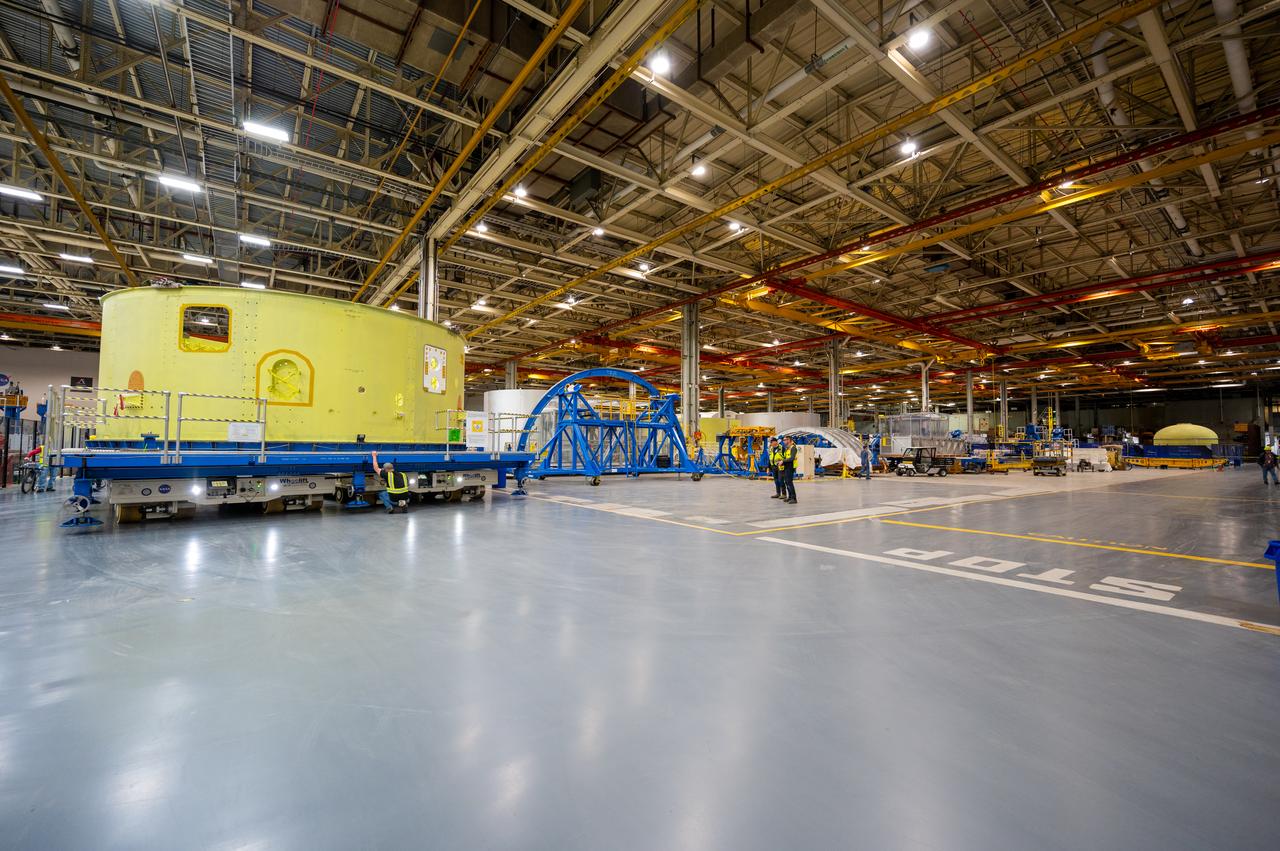
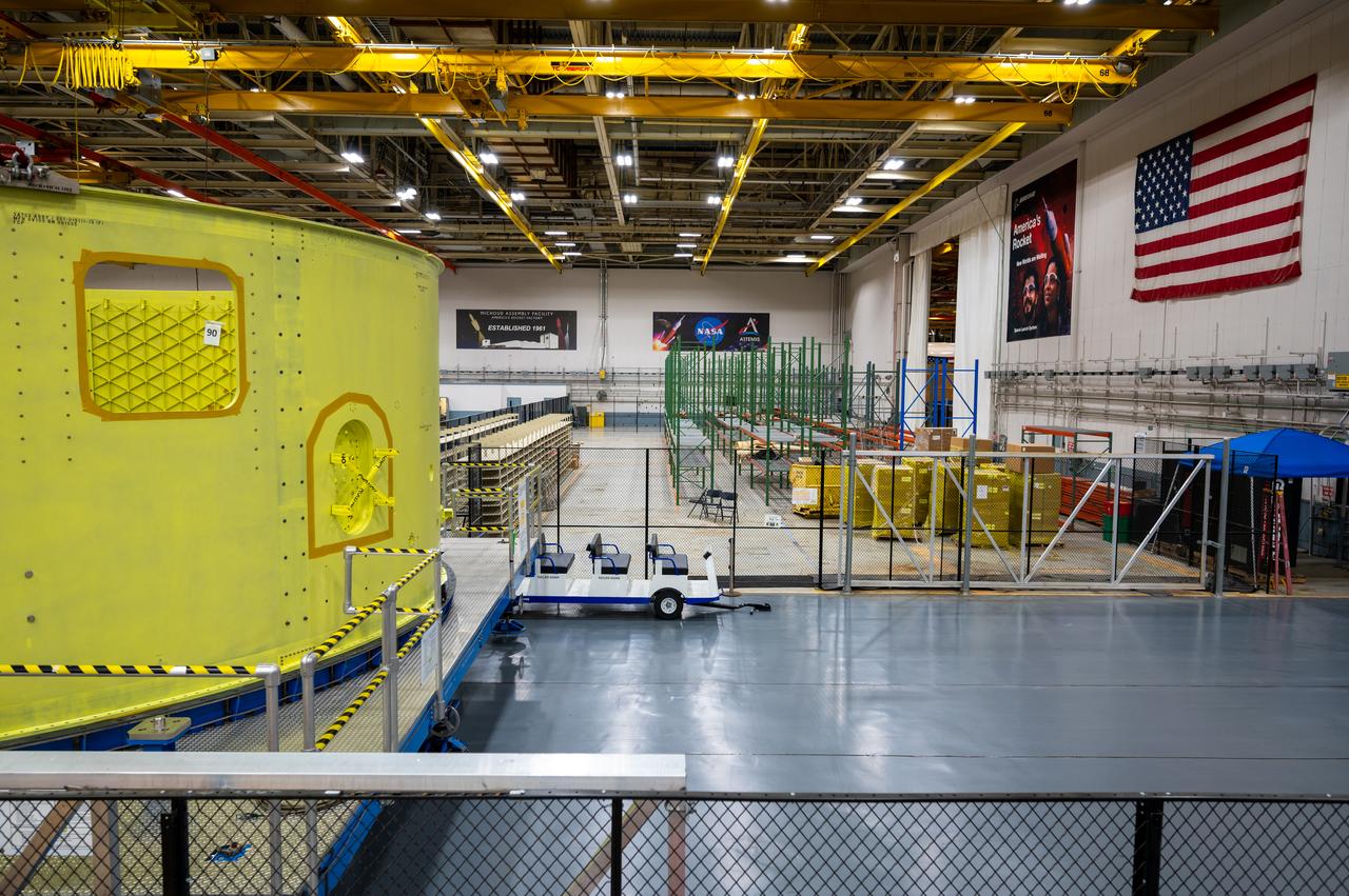
Crews at NASA’s Michoud Assembly Facility in New Orleans move the forward skirt of NASA’s Space Launch System (SLS) rocket to another part of the facility Dec. 15. Teams are preparing to apply the thermal protection system to the flight hardware, which will protect it from the extreme temperatures during launch and flight. The forward skirt is part of the core stage that will power the SLS rocket for the Artemis III mission. The forward skirt houses flight computers, cameras, and avionics.. The SLS core stage is made up of five unique elements: the forward skirt, liquid oxygen tank, intertank, liquid hydrogen tank, and the engine section. When fully stacked, the forward skirt is located at the top of the core stage and connects the stage to the upper part of the rocket. Together with its four RS-25 engines, the rocket’s massive 212-foot-tall core stage — the largest stage NASA has ever built — and its twin solid rocket boosters produce 8.8 million pounds of thrust to send NASA’s Orion spacecraft, astronauts and supplies beyond Earth’s orbit to the Moon and, ultimately, Mars. Offering more payload mass, volume capability and energy to speed missions through space, the SLS rocket, along with NASA’s Gateway in lunar orbit, the Human Landing System, and Orion spacecraft, is part of NASA’s backbone for deep space exploration and the Artemis lunar program. No other rocket is capable of carrying astronauts in Orion around the Moon in a single mission.
Crews at NASA’s Michoud Assembly Facility in New Orleans move the forward skirt of NASA’s Space Launch System (SLS) rocket to another part of the facility Dec. 15. Teams are preparing to apply the thermal protection system to the flight hardware, which will protect it from the extreme temperatures during launch and flight. The forward skirt is part of the core stage that will power the SLS rocket for the Artemis III mission. The forward skirt houses flight computers, cameras, and avionics.. The SLS core stage is made up of five unique elements: the forward skirt, liquid oxygen tank, intertank, liquid hydrogen tank, and the engine section. When fully stacked, the forward skirt is located at the top of the core stage and connects the stage to the upper part of the rocket. Together with its four RS-25 engines, the rocket’s massive 212-foot-tall core stage — the largest stage NASA has ever built — and its twin solid rocket boosters produce 8.8 million pounds of thrust to send NASA’s Orion spacecraft, astronauts and supplies beyond Earth’s orbit to the Moon and, ultimately, Mars. Offering more payload mass, volume capability and energy to speed missions through space, the SLS rocket, along with NASA’s Gateway in lunar orbit, the Human Landing System, and Orion spacecraft, is part of NASA’s backbone for deep space exploration and the Artemis lunar program. No other rocket is capable of carrying astronauts in Orion around the Moon in a single mission.
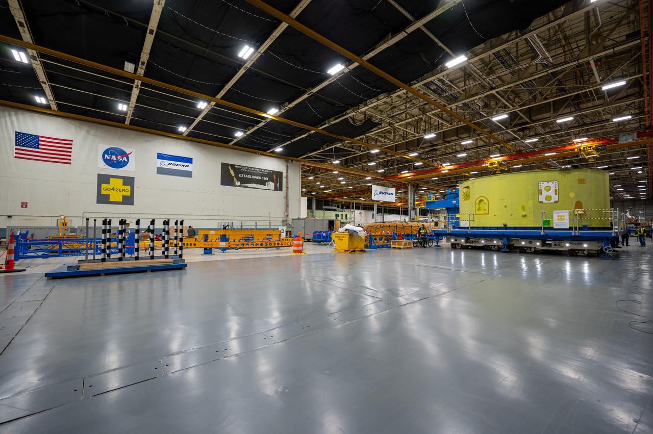
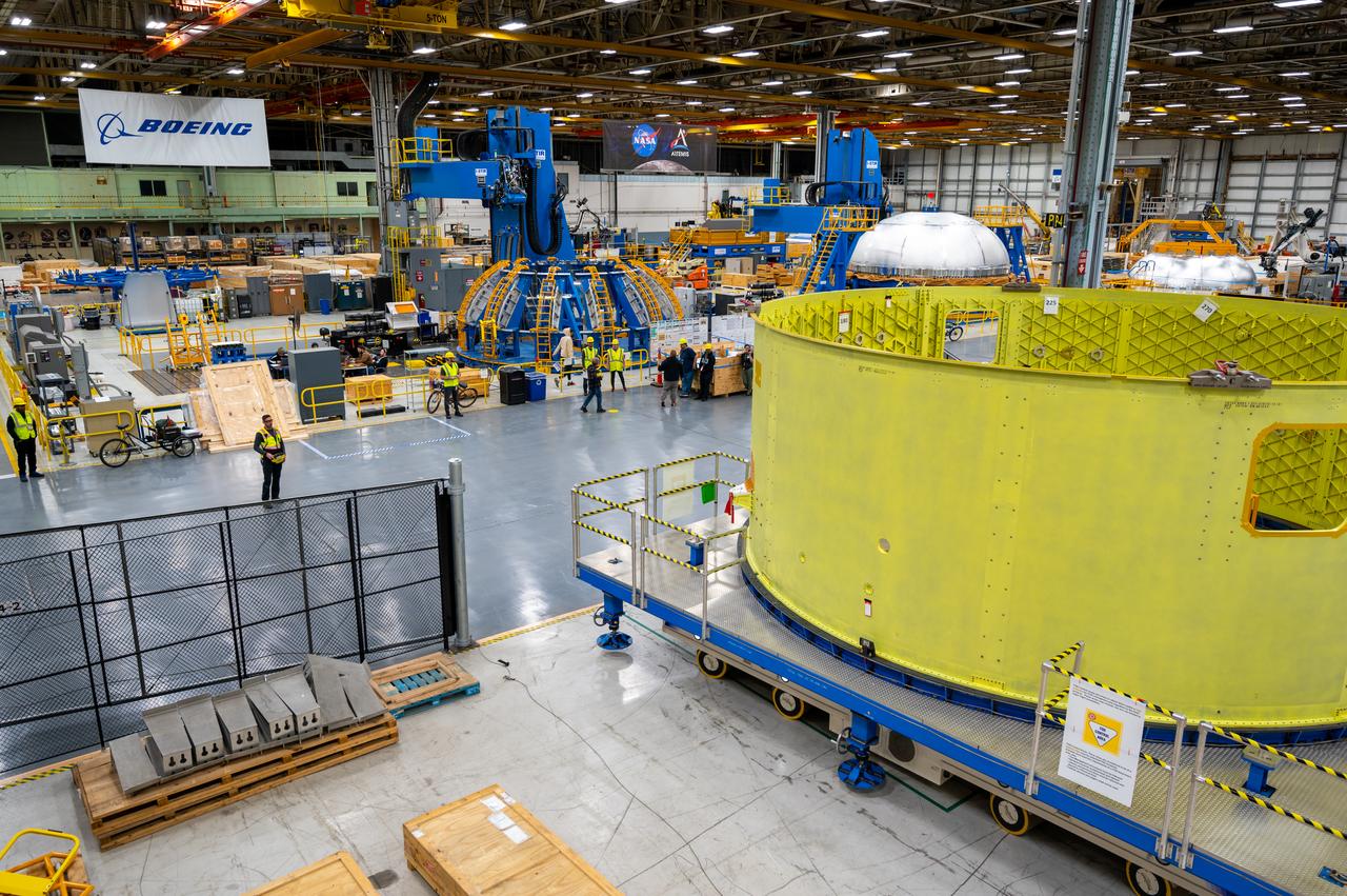
Crews at NASA’s Michoud Assembly Facility in New Orleans move the forward skirt of NASA’s Space Launch System (SLS) rocket to another part of the facility Dec. 15. Teams are preparing to apply the thermal protection system to the flight hardware, which will protect it from the extreme temperatures during launch and flight. The forward skirt is part of the core stage that will power the SLS rocket for the Artemis III mission. The forward skirt houses flight computers, cameras, and avionics.. The SLS core stage is made up of five unique elements: the forward skirt, liquid oxygen tank, intertank, liquid hydrogen tank, and the engine section. When fully stacked, the forward skirt is located at the top of the core stage and connects the stage to the upper part of the rocket. Together with its four RS-25 engines, the rocket’s massive 212-foot-tall core stage — the largest stage NASA has ever built — and its twin solid rocket boosters produce 8.8 million pounds of thrust to send NASA’s Orion spacecraft, astronauts and supplies beyond Earth’s orbit to the Moon and, ultimately, Mars. Offering more payload mass, volume capability and energy to speed missions through space, the SLS rocket, along with NASA’s Gateway in lunar orbit, the Human Landing System, and Orion spacecraft, is part of NASA’s backbone for deep space exploration and the Artemis lunar program. No other rocket is capable of carrying astronauts in Orion around the Moon in a single mission.
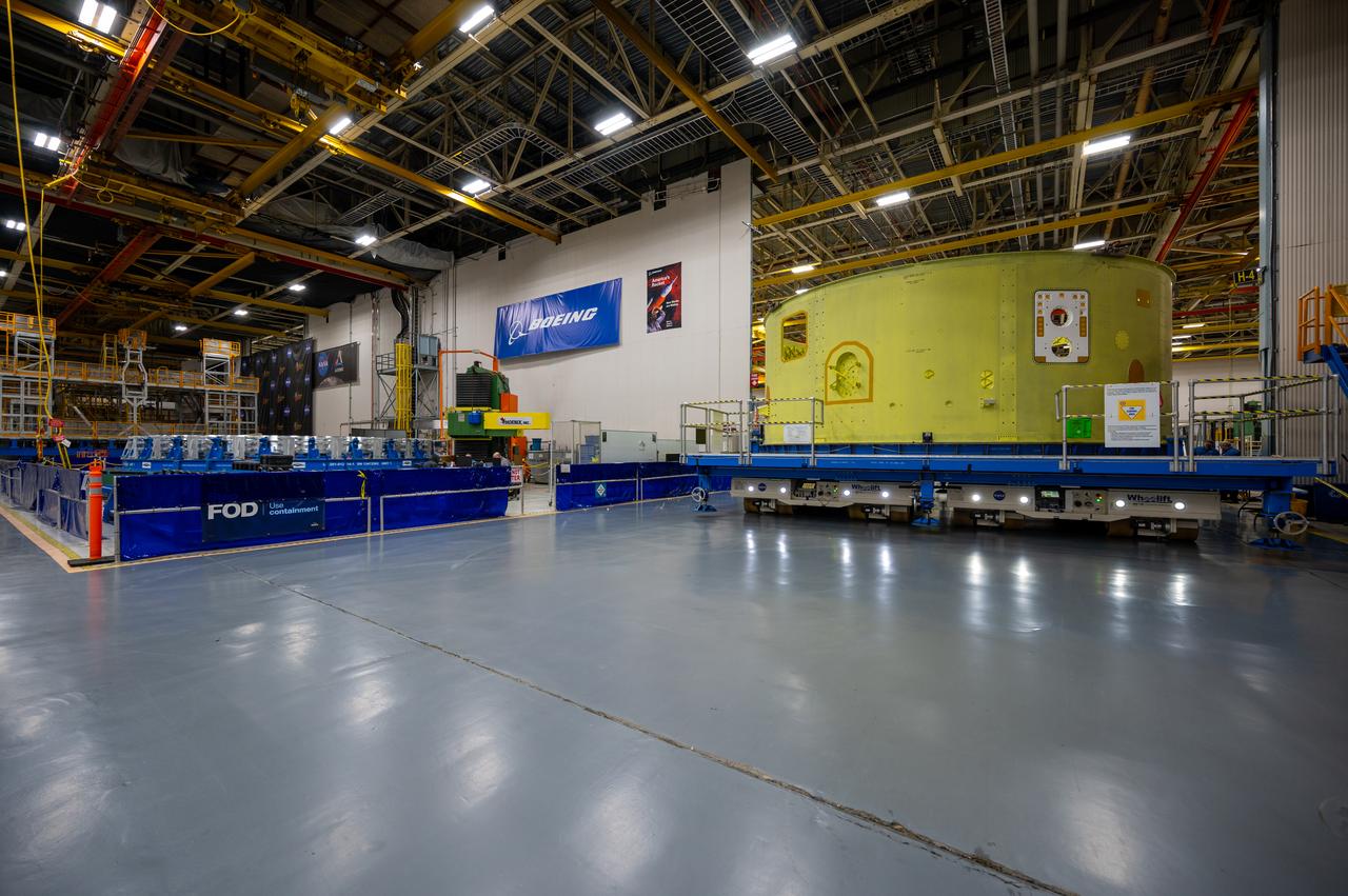
Crews at NASA’s Michoud Assembly Facility in New Orleans move the forward skirt of NASA’s Space Launch System (SLS) rocket to another part of the facility Dec. 15. Teams are preparing to apply the thermal protection system to the flight hardware, which will protect it from the extreme temperatures during launch and flight. The forward skirt is part of the core stage that will power the SLS rocket for the Artemis III mission. The forward skirt houses flight computers, cameras, and avionics.. The SLS core stage is made up of five unique elements: the forward skirt, liquid oxygen tank, intertank, liquid hydrogen tank, and the engine section. When fully stacked, the forward skirt is located at the top of the core stage and connects the stage to the upper part of the rocket. Together with its four RS-25 engines, the rocket’s massive 212-foot-tall core stage — the largest stage NASA has ever built — and its twin solid rocket boosters produce 8.8 million pounds of thrust to send NASA’s Orion spacecraft, astronauts and supplies beyond Earth’s orbit to the Moon and, ultimately, Mars. Offering more payload mass, volume capability and energy to speed missions through space, the SLS rocket, along with NASA’s Gateway in lunar orbit, the Human Landing System, and Orion spacecraft, is part of NASA’s backbone for deep space exploration and the Artemis lunar program. No other rocket is capable of carrying astronauts in Orion around the Moon in a single mission.
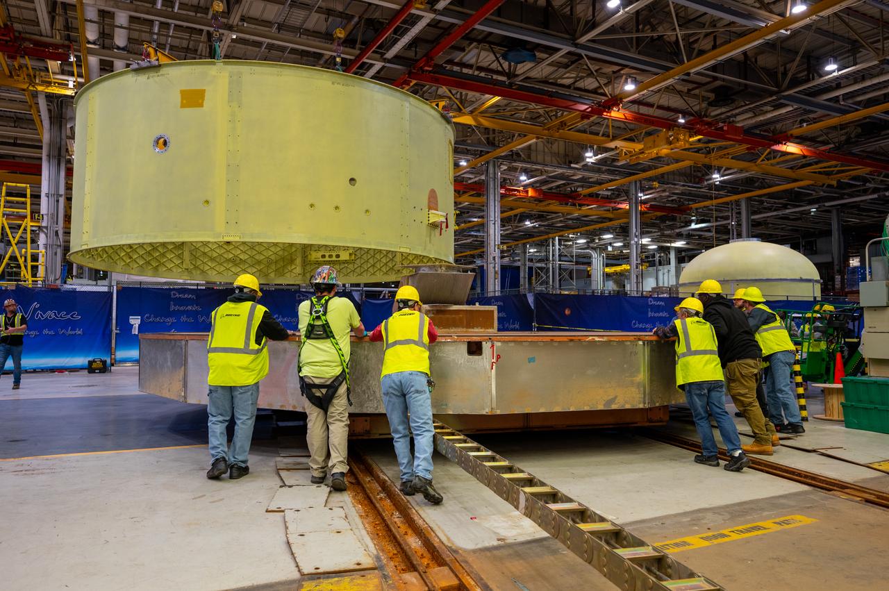
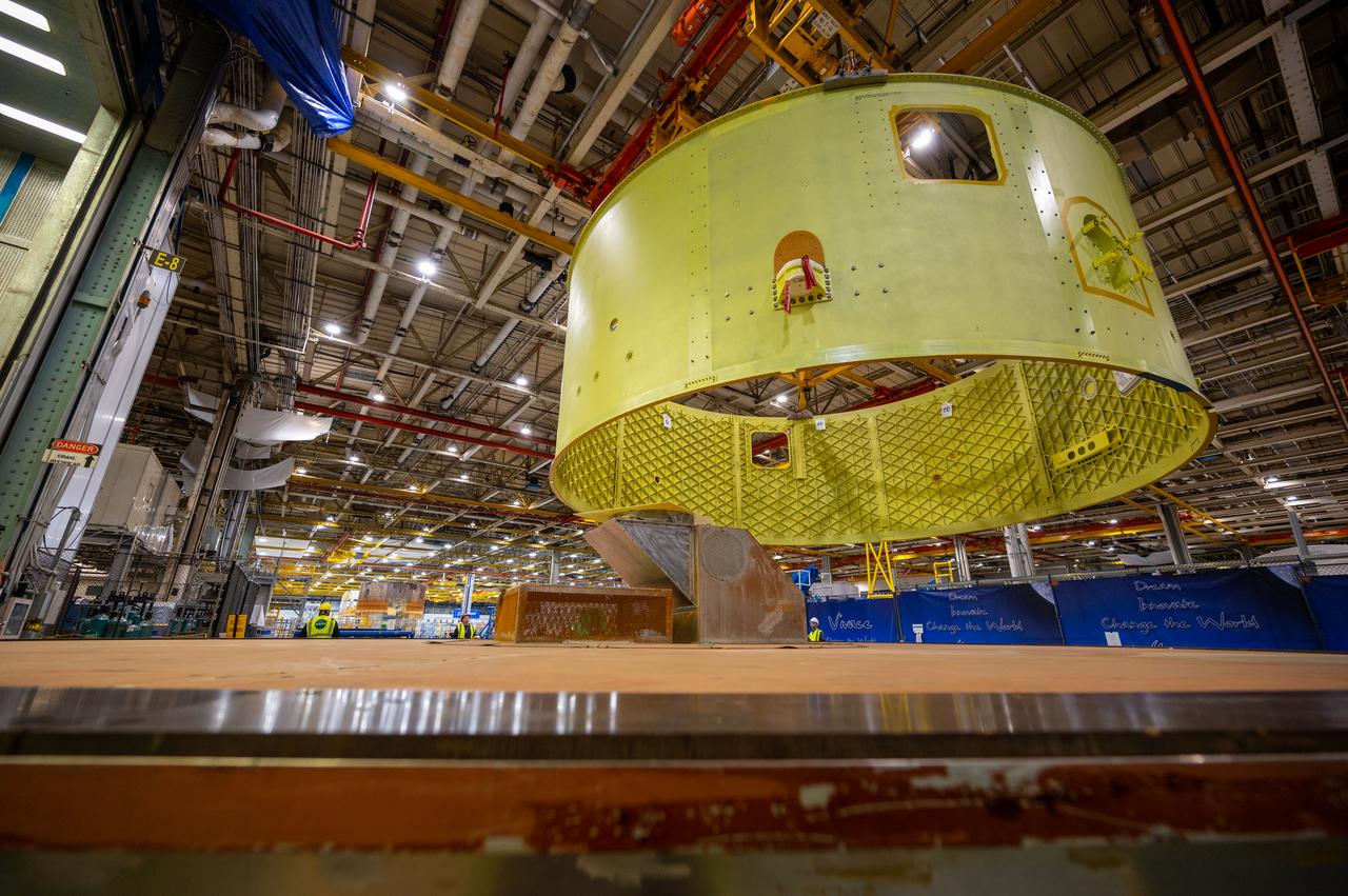
Crews at NASA’s Michoud Assembly Facility in New Orleans move the forward skirt of NASA’s Space Launch System (SLS) rocket to another part of the facility Dec. 15. Teams are preparing to apply the thermal protection system to the flight hardware, which will protect it from the extreme temperatures during launch and flight. The forward skirt is part of the core stage that will power the SLS rocket for the Artemis III mission. The forward skirt houses flight computers, cameras, and avionics.. The SLS core stage is made up of five unique elements: the forward skirt, liquid oxygen tank, intertank, liquid hydrogen tank, and the engine section. When fully stacked, the forward skirt is located at the top of the core stage and connects the stage to the upper part of the rocket. Together with its four RS-25 engines, the rocket’s massive 212-foot-tall core stage — the largest stage NASA has ever built — and its twin solid rocket boosters produce 8.8 million pounds of thrust to send NASA’s Orion spacecraft, astronauts and supplies beyond Earth’s orbit to the Moon and, ultimately, Mars. Offering more payload mass, volume capability and energy to speed missions through space, the SLS rocket, along with NASA’s Gateway in lunar orbit, the Human Landing System, and Orion spacecraft, is part of NASA’s backbone for deep space exploration and the Artemis lunar program. No other rocket is capable of carrying astronauts in Orion around the Moon in a single mission.
Crews at NASA’s Michoud Assembly Facility in New Orleans move the forward skirt of NASA’s Space Launch System (SLS) rocket to another part of the facility Dec. 15. Teams are preparing to apply the thermal protection system to the flight hardware, which will protect it from the extreme temperatures during launch and flight. The forward skirt is part of the core stage that will power the SLS rocket for the Artemis III mission. The forward skirt houses flight computers, cameras, and avionics.. The SLS core stage is made up of five unique elements: the forward skirt, liquid oxygen tank, intertank, liquid hydrogen tank, and the engine section. When fully stacked, the forward skirt is located at the top of the core stage and connects the stage to the upper part of the rocket. Together with its four RS-25 engines, the rocket’s massive 212-foot-tall core stage — the largest stage NASA has ever built — and its twin solid rocket boosters produce 8.8 million pounds of thrust to send NASA’s Orion spacecraft, astronauts and supplies beyond Earth’s orbit to the Moon and, ultimately, Mars. Offering more payload mass, volume capability and energy to speed missions through space, the SLS rocket, along with NASA’s Gateway in lunar orbit, the Human Landing System, and Orion spacecraft, is part of NASA’s backbone for deep space exploration and the Artemis lunar program. No other rocket is capable of carrying astronauts in Orion around the Moon in a single mission.
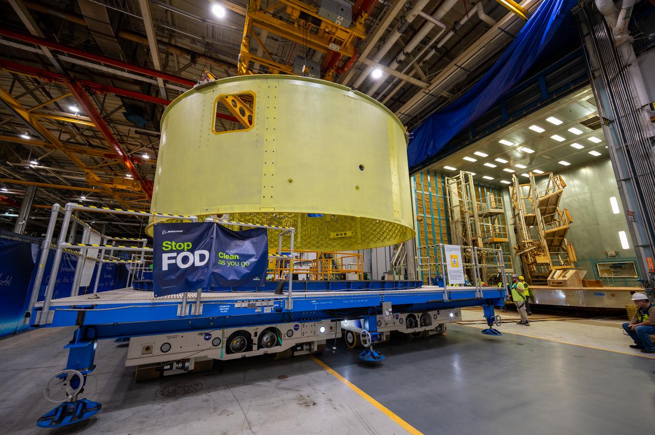
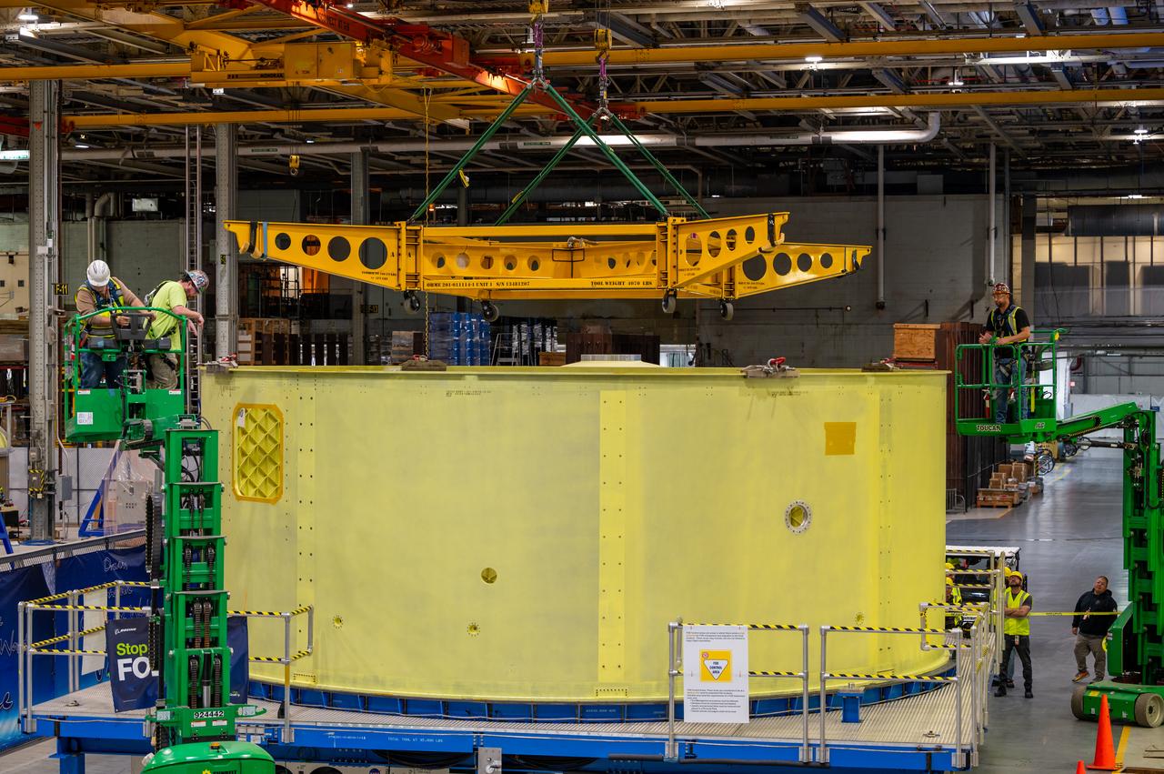
Crews at NASA’s Michoud Assembly Facility in New Orleans move the forward skirt of NASA’s Space Launch System (SLS) rocket to another part of the facility Dec. 15. Teams are preparing to apply the thermal protection system to the flight hardware, which will protect it from the extreme temperatures during launch and flight. The forward skirt is part of the core stage that will power the SLS rocket for the Artemis III mission. The forward skirt houses flight computers, cameras, and avionics.. The SLS core stage is made up of five unique elements: the forward skirt, liquid oxygen tank, intertank, liquid hydrogen tank, and the engine section. When fully stacked, the forward skirt is located at the top of the core stage and connects the stage to the upper part of the rocket. Together with its four RS-25 engines, the rocket’s massive 212-foot-tall core stage — the largest stage NASA has ever built — and its twin solid rocket boosters produce 8.8 million pounds of thrust to send NASA’s Orion spacecraft, astronauts and supplies beyond Earth’s orbit to the Moon and, ultimately, Mars. Offering more payload mass, volume capability and energy to speed missions through space, the SLS rocket, along with NASA’s Gateway in lunar orbit, the Human Landing System, and Orion spacecraft, is part of NASA’s backbone for deep space exploration and the Artemis lunar program. No other rocket is capable of carrying astronauts in Orion around the Moon in a single mission.
Crews at NASA’s Michoud Assembly Facility in New Orleans move the forward skirt of NASA’s Space Launch System (SLS) rocket to another part of the facility Dec. 15. Teams are preparing to apply the thermal protection system to the flight hardware, which will protect it from the extreme temperatures during launch and flight. The forward skirt is part of the core stage that will power the SLS rocket for the Artemis III mission. The forward skirt houses flight computers, cameras, and avionics.. The SLS core stage is made up of five unique elements: the forward skirt, liquid oxygen tank, intertank, liquid hydrogen tank, and the engine section. When fully stacked, the forward skirt is located at the top of the core stage and connects the stage to the upper part of the rocket. Together with its four RS-25 engines, the rocket’s massive 212-foot-tall core stage — the largest stage NASA has ever built — and its twin solid rocket boosters produce 8.8 million pounds of thrust to send NASA’s Orion spacecraft, astronauts and supplies beyond Earth’s orbit to the Moon and, ultimately, Mars. Offering more payload mass, volume capability and energy to speed missions through space, the SLS rocket, along with NASA’s Gateway in lunar orbit, the Human Landing System, and Orion spacecraft, is part of NASA’s backbone for deep space exploration and the Artemis lunar program. No other rocket is capable of carrying astronauts in Orion around the Moon in a single mission.
Crews at NASA’s Michoud Assembly Facility in New Orleans move the forward skirt of NASA’s Space Launch System (SLS) rocket to another part of the facility Dec. 15. Teams are preparing to apply the thermal protection system to the flight hardware, which will protect it from the extreme temperatures during launch and flight. The forward skirt is part of the core stage that will power the SLS rocket for the Artemis III mission. The forward skirt houses flight computers, cameras, and avionics.. The SLS core stage is made up of five unique elements: the forward skirt, liquid oxygen tank, intertank, liquid hydrogen tank, and the engine section. When fully stacked, the forward skirt is located at the top of the core stage and connects the stage to the upper part of the rocket. Together with its four RS-25 engines, the rocket’s massive 212-foot-tall core stage — the largest stage NASA has ever built — and its twin solid rocket boosters produce 8.8 million pounds of thrust to send NASA’s Orion spacecraft, astronauts and supplies beyond Earth’s orbit to the Moon and, ultimately, Mars. Offering more payload mass, volume capability and energy to speed missions through space, the SLS rocket, along with NASA’s Gateway in lunar orbit, the Human Landing System, and Orion spacecraft, is part of NASA’s backbone for deep space exploration and the Artemis lunar program. No other rocket is capable of carrying astronauts in Orion around the Moon in a single mission.
Crews at NASA’s Michoud Assembly Facility in New Orleans move the forward skirt of NASA’s Space Launch System (SLS) rocket to another part of the facility Dec. 15. Teams are preparing to apply the thermal protection system to the flight hardware, which will protect it from the extreme temperatures during launch and flight. The forward skirt is part of the core stage that will power the SLS rocket for the Artemis III mission. The forward skirt houses flight computers, cameras, and avionics.. The SLS core stage is made up of five unique elements: the forward skirt, liquid oxygen tank, intertank, liquid hydrogen tank, and the engine section. When fully stacked, the forward skirt is located at the top of the core stage and connects the stage to the upper part of the rocket. Together with its four RS-25 engines, the rocket’s massive 212-foot-tall core stage — the largest stage NASA has ever built — and its twin solid rocket boosters produce 8.8 million pounds of thrust to send NASA’s Orion spacecraft, astronauts and supplies beyond Earth’s orbit to the Moon and, ultimately, Mars. Offering more payload mass, volume capability and energy to speed missions through space, the SLS rocket, along with NASA’s Gateway in lunar orbit, the Human Landing System, and Orion spacecraft, is part of NASA’s backbone for deep space exploration and the Artemis lunar program. No other rocket is capable of carrying astronauts in Orion around the Moon in a single mission.
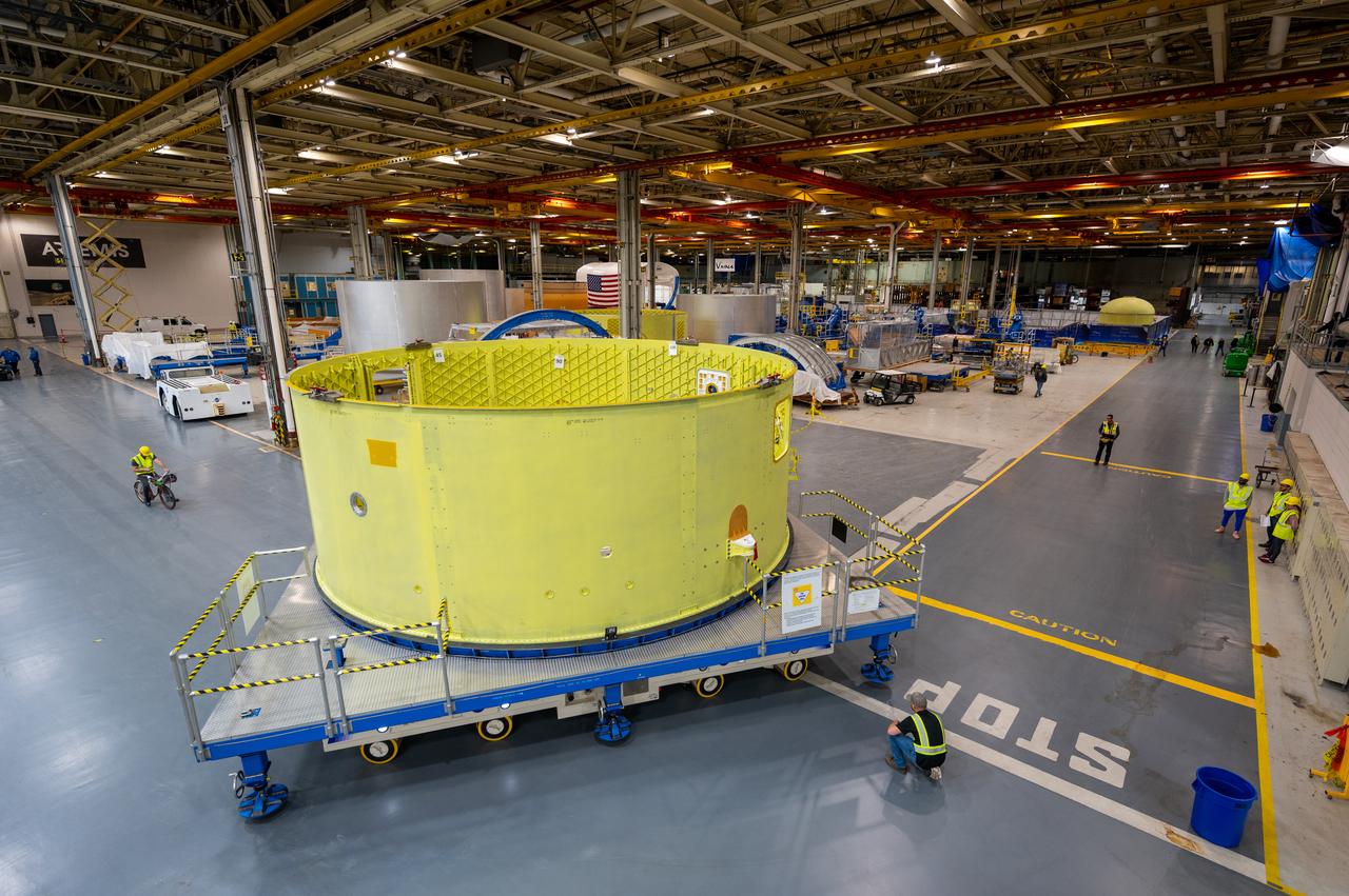
Crews at NASA’s Michoud Assembly Facility in New Orleans move the forward skirt of NASA’s Space Launch System (SLS) rocket to another part of the facility Dec. 15. Teams are preparing to apply the thermal protection system to the flight hardware, which will protect it from the extreme temperatures during launch and flight. The forward skirt is part of the core stage that will power the SLS rocket for the Artemis III mission. The forward skirt houses flight computers, cameras, and avionics.. The SLS core stage is made up of five unique elements: the forward skirt, liquid oxygen tank, intertank, liquid hydrogen tank, and the engine section. When fully stacked, the forward skirt is located at the top of the core stage and connects the stage to the upper part of the rocket. Together with its four RS-25 engines, the rocket’s massive 212-foot-tall core stage — the largest stage NASA has ever built — and its twin solid rocket boosters produce 8.8 million pounds of thrust to send NASA’s Orion spacecraft, astronauts and supplies beyond Earth’s orbit to the Moon and, ultimately, Mars. Offering more payload mass, volume capability and energy to speed missions through space, the SLS rocket, along with NASA’s Gateway in lunar orbit, the Human Landing System, and Orion spacecraft, is part of NASA’s backbone for deep space exploration and the Artemis lunar program. No other rocket is capable of carrying astronauts in Orion around the Moon in a single mission.
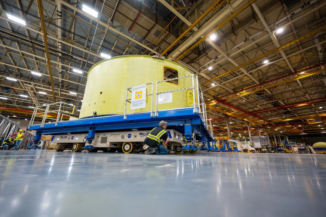
Crews at NASA’s Michoud Assembly Facility in New Orleans move the forward skirt of NASA’s Space Launch System (SLS) rocket to another part of the facility Dec. 15. Teams are preparing to apply the thermal protection system to the flight hardware, which will protect it from the extreme temperatures during launch and flight. The forward skirt is part of the core stage that will power the SLS rocket for the Artemis III mission. The forward skirt houses flight computers, cameras, and avionics.. The SLS core stage is made up of five unique elements: the forward skirt, liquid oxygen tank, intertank, liquid hydrogen tank, and the engine section. When fully stacked, the forward skirt is located at the top of the core stage and connects the stage to the upper part of the rocket. Together with its four RS-25 engines, the rocket’s massive 212-foot-tall core stage — the largest stage NASA has ever built — and its twin solid rocket boosters produce 8.8 million pounds of thrust to send NASA’s Orion spacecraft, astronauts and supplies beyond Earth’s orbit to the Moon and, ultimately, Mars. Offering more payload mass, volume capability and energy to speed missions through space, the SLS rocket, along with NASA’s Gateway in lunar orbit, the Human Landing System, and Orion spacecraft, is part of NASA’s backbone for deep space exploration and the Artemis lunar program. No other rocket is capable of carrying astronauts in Orion around the Moon in a single mission.
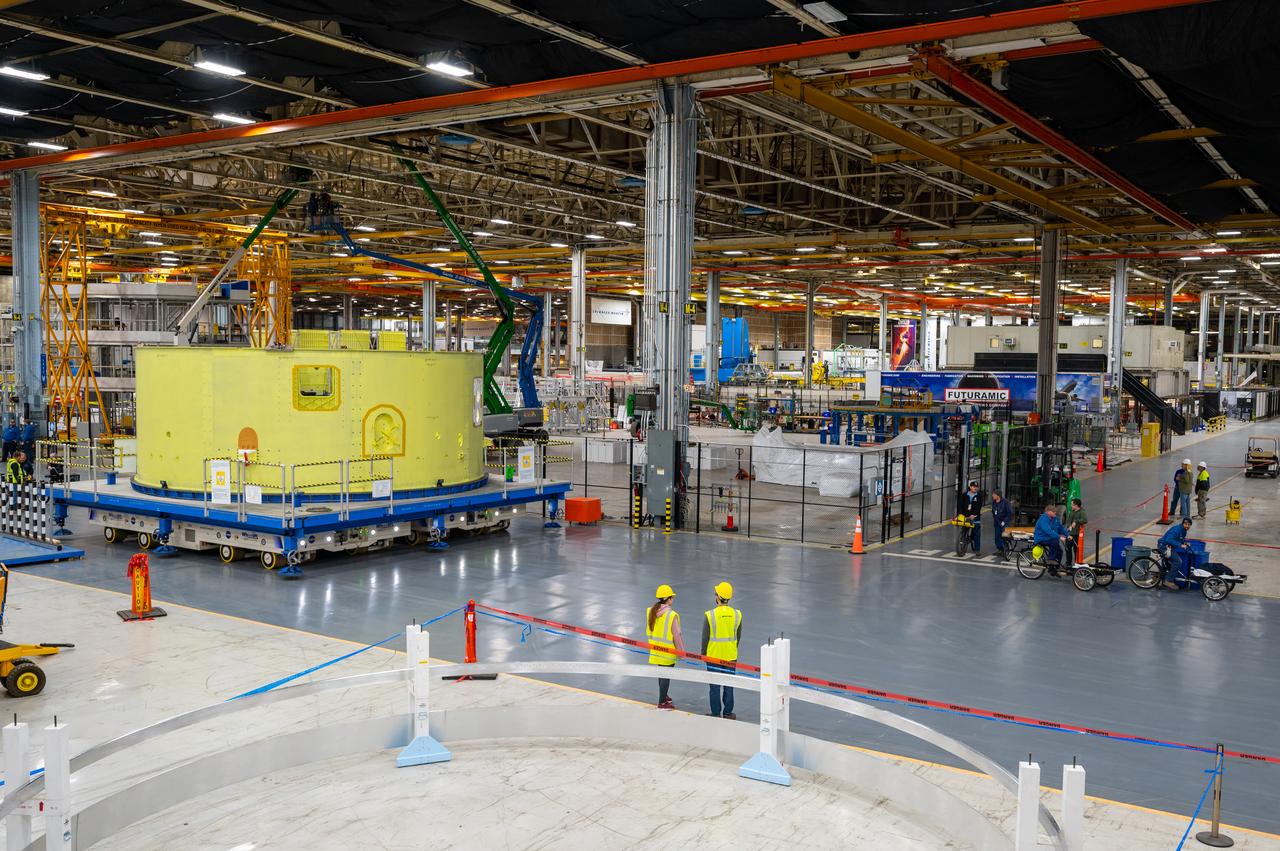
Crews at NASA’s Michoud Assembly Facility in New Orleans move the forward skirt of NASA’s Space Launch System (SLS) rocket to another part of the facility Dec. 15. Teams are preparing to apply the thermal protection system to the flight hardware, which will protect it from the extreme temperatures during launch and flight. The forward skirt is part of the core stage that will power the SLS rocket for the Artemis III mission. The forward skirt houses flight computers, cameras, and avionics.. The SLS core stage is made up of five unique elements: the forward skirt, liquid oxygen tank, intertank, liquid hydrogen tank, and the engine section. When fully stacked, the forward skirt is located at the top of the core stage and connects the stage to the upper part of the rocket. Together with its four RS-25 engines, the rocket’s massive 212-foot-tall core stage — the largest stage NASA has ever built — and its twin solid rocket boosters produce 8.8 million pounds of thrust to send NASA’s Orion spacecraft, astronauts and supplies beyond Earth’s orbit to the Moon and, ultimately, Mars. Offering more payload mass, volume capability and energy to speed missions through space, the SLS rocket, along with NASA’s Gateway in lunar orbit, the Human Landing System, and Orion spacecraft, is part of NASA’s backbone for deep space exploration and the Artemis lunar program. No other rocket is capable of carrying astronauts in Orion around the Moon in a single mission.

ISS036-E-035635 (24 Aug. 2013) --- Plankton bloom and Lake Ontario are featured in this image photographed by an Expedition 36 crew member on the International Space Station. This photograph highlights a late summer plankton bloom visible throughout much of Lake Ontario (one of the Great Lakes, together with Michigan, Superior, Erie, and Huron). Cyanobacteria, or blue-green algae, can reach such large concentrations that they color the water to such an extent that the change is visible from orbit. Harmful algal blooms, or HABs, have been observed in all of the Great Lakes – particularly Lake Erie - and are associated with a variety of causative factors including changes in precipitation; drought; invasive species (quagga, zebra mussels, Asian carp); nutrient loading from runoff and sewage (nitrogen and phosphorus); and warmer average temperatures. In addition to reduced water quality and human health concerns, algal blooms can also lead to hypoxia (reduction of oxygen in the bottom waters) that kills large numbers of fish and other aquatic life. Lake Ontario, like the other Great Lakes Erie, Huron, and Superior is roughly divided between the USA and Canada. The USA side of Lake Ontario has its shoreline along the state of New York, while its Canadian shoreline lies within the province of Ontario. The city of Kingston, Ontario, is visible near the Saint Lawrence River outflow from the lake. Several other landscape features of New York State are visible in the image, including the Finger Lakes region to the west of Syracuse, NY (upper left). To the northeast of Syracuse, the dark wooded slopes of the Adirondack Mountains are visible at lower right. Patchy white cloud cover obscures much of the land surface to the west of Lake Ontario.

Canada has already had its share of wildfires this season, and the smoke from these wildfires is slowly drifting south over the United States' Midwest. The drifting smoke can be seen in this Terra satellite image over Lake Michigan, as well as parts of Minnesota, Wisconsin, Indiana and Ohio. The smoke released by any type of fire (forest, brush, crop, structure, tires, waste or wood burning) is a mixture of particles and chemicals produced by incomplete burning of carbon-containing materials. All smoke contains carbon monoxide, carbon dioxide and particulate matter (PM or soot). Smoke can contain many different chemicals, including aldehydes, acid gases, sulfur dioxide, nitrogen oxides, polycyclic aromatic hydrocarbons (PAHs), benzene, toluene, styrene, metals and dioxins. The type and amount of particles and chemicals in smoke varies depending on what is burning, how much oxygen is available, and the burn temperature. Exposure to any type of smoke should be avoided if possible, but especially by those with respiratory issues, the elderly, and children. This natural-color satellite image was collected by the Moderate Resolution Imaging Spectroradiometer (MODIS) aboard the Terra satellite on June 09, 2015. Credit: NASA image courtesy Jeff Schmaltz, MODIS Rapid Response Team <b><a href="http://www.nasa.gov/audience/formedia/features/MP_Photo_Guidelines.html" rel="nofollow">NASA image use policy.</a></b> <b><a href="http://www.nasa.gov/centers/goddard/home/index.html" rel="nofollow">NASA Goddard Space Flight Center</a></b> enables NASA’s mission through four scientific endeavors: Earth Science, Heliophysics, Solar System Exploration, and Astrophysics. Goddard plays a leading role in NASA’s accomplishments by contributing compelling scientific knowledge to advance the Agency’s mission. <b>Follow us on <a href="http://twitter.com/NASAGoddardPix" rel="nofollow">Twitter</a></b> <b>Like us on <a href="http://www.facebook.com/pages/Greenbelt-MD/NASA-Goddard/395013845897?ref=tsd" rel="nofollow">Facebook</a></b> <b>Find us on <a href="http://instagrid.me/nasagoddard/?vm=grid" rel="nofollow">Instagram</a></b>

A massive phytoplankton bloom stained the waters of the Atlantic Ocean north of Iceland with brilliant jewel tones in late summer, 2014. The Moderate Resolution Imaging Spectroradiometer (MODIS) aboard NASA’s Aqua satellite captured this true-color image on August 2. Huge colonies of the floating, plant-like organisms create swirls of green, teal and turquoise and cover over 80% of the visible ocean off the northeast coast of Iceland. Marine phytoplankton require just the right amount of sunlight, dissolved nutrients and water temperatures which are not too hot, nor too cold to spark explosive reproduction and result in blooms which can cover hundreds of square kilometers. Phytoplankton form the base of the marine food chain, and are a rich food source for zooplankton, fish and other marine species. Some species, however, can deplete the water of oxygen and may become toxic to marine life. Credit: NASA/GSFC/Jeff Schmaltz/MODIS Land Rapid Response Team <b><a href="http://www.nasa.gov/audience/formedia/features/MP_Photo_Guidelines.html" rel="nofollow">NASA image use policy.</a></b> <b><a href="http://www.nasa.gov/centers/goddard/home/index.html" rel="nofollow">NASA Goddard Space Flight Center</a></b> enables NASA’s mission through four scientific endeavors: Earth Science, Heliophysics, Solar System Exploration, and Astrophysics. Goddard plays a leading role in NASA’s accomplishments by contributing compelling scientific knowledge to advance the Agency’s mission. <b>Follow us on <a href="http://twitter.com/NASAGoddardPix" rel="nofollow">Twitter</a></b> <b>Like us on <a href="http://www.facebook.com/pages/Greenbelt-MD/NASA-Goddard/395013845897?ref=tsd" rel="nofollow">Facebook</a></b> <b>Find us on <a href="http://instagram.com/nasagoddard?vm=grid" rel="nofollow">Instagram</a></b>

On July 23, 2013 the deep blue waters of the central North Atlantic Ocean provided a background for a spectacular bloom of phytoplankton. The Moderate Resolution Imaging Spectroradiometer (MODIS) captured this true-color image of the event at 16:25 UTC (12:25 p.m. EDT) that same day. Phytoplankton are tiny single-celled photosynthetic organisms that live suspended in a watery environment. They are primary producers in the ocean, forming the base of the marine food chain, and, like terrestrial plants, take up carbon dioxide, make carbohydrates from energy from light, and release oxygen. Phytoplankton live in the ocean year round, but are usually not visible. When light, nutrients and water temperature are just right, however, a colony can explode into growth, creating huge blooms that stain the ocean for miles. While each organism lives only a short time, the high reproductive means that a bloom can last for days or weeks. Credit: NASA/GSFC/Jeff Schmaltz/MODIS Land Rapid Response Team <b><a href="http://www.nasa.gov/audience/formedia/features/MP_Photo_Guidelines.html" rel="nofollow">NASA image use policy.</a></b> <b><a href="http://www.nasa.gov/centers/goddard/home/index.html" rel="nofollow">NASA Goddard Space Flight Center</a></b> enables NASA’s mission through four scientific endeavors: Earth Science, Heliophysics, Solar System Exploration, and Astrophysics. Goddard plays a leading role in NASA’s accomplishments by contributing compelling scientific knowledge to advance the Agency’s mission. <b>Follow us on <a href="http://twitter.com/NASA_GoddardPix" rel="nofollow">Twitter</a></b> <b>Like us on <a href="http://www.facebook.com/pages/Greenbelt-MD/NASA-Goddard/395013845897?ref=tsd" rel="nofollow">Facebook</a></b> <b>Find us on <a href="http://instagram.com/nasagoddard?vm=grid" rel="nofollow">Instagram</a></b>
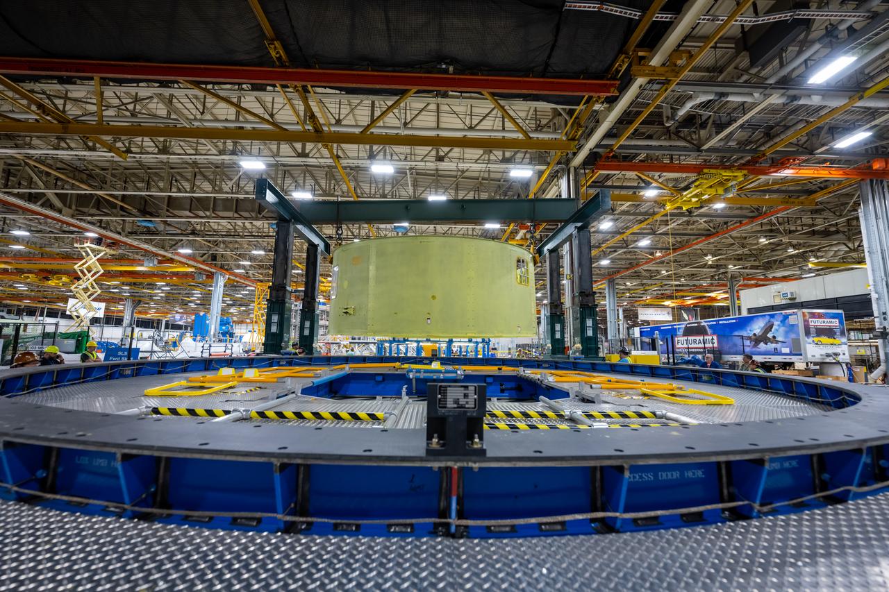
Crews at NASA’s Michoud Assembly Facility in New Orleans move the forward skirt of NASA’s Space Launch System (SLS) rocket to another part of the facility Dec. 15. Teams are preparing to apply the thermal protection system to the flight hardware, which will protect it from the extreme temperatures during launch and flight. The forward skirt is part of the core stage that will power the SLS rocket for the Artemis III mission. The forward skirt houses flight computers, cameras, and avionics.. The SLS core stage is made up of five unique elements: the forward skirt, liquid oxygen tank, intertank, liquid hydrogen tank, and the engine section. When fully stacked, the forward skirt is located at the top of the core stage and connects the stage to the upper part of the rocket. Together with its four RS-25 engines, the rocket’s massive 212-foot-tall core stage — the largest stage NASA has ever built — and its twin solid rocket boosters produce 8.8 million pounds of thrust to send NASA’s Orion spacecraft, astronauts and supplies beyond Earth’s orbit to the Moon and, ultimately, Mars. Offering more payload mass, volume capability and energy to speed missions through space, the SLS rocket, along with NASA’s Gateway in lunar orbit, the Human Landing System, and Orion spacecraft, is part of NASA’s backbone for deep space exploration and the Artemis lunar program. No other rocket is capable of carrying astronauts in Orion around the Moon in a single mission.

Crews at NASA’s Michoud Assembly Facility in New Orleans move the forward skirt of NASA’s Space Launch System (SLS) rocket to another part of the facility Dec. 15. Teams are preparing to apply the thermal protection system to the flight hardware, which will protect it from the extreme temperatures during launch and flight. The forward skirt is part of the core stage that will power the SLS rocket for the Artemis III mission. The forward skirt houses flight computers, cameras, and avionics.. The SLS core stage is made up of five unique elements: the forward skirt, liquid oxygen tank, intertank, liquid hydrogen tank, and the engine section. When fully stacked, the forward skirt is located at the top of the core stage and connects the stage to the upper part of the rocket. Together with its four RS-25 engines, the rocket’s massive 212-foot-tall core stage — the largest stage NASA has ever built — and its twin solid rocket boosters produce 8.8 million pounds of thrust to send NASA’s Orion spacecraft, astronauts and supplies beyond Earth’s orbit to the Moon and, ultimately, Mars. Offering more payload mass, volume capability and energy to speed missions through space, the SLS rocket, along with NASA’s Gateway in lunar orbit, the Human Landing System, and Orion spacecraft, is part of NASA’s backbone for deep space exploration and the Artemis lunar program. No other rocket is capable of carrying astronauts in Orion around the Moon in a single mission.
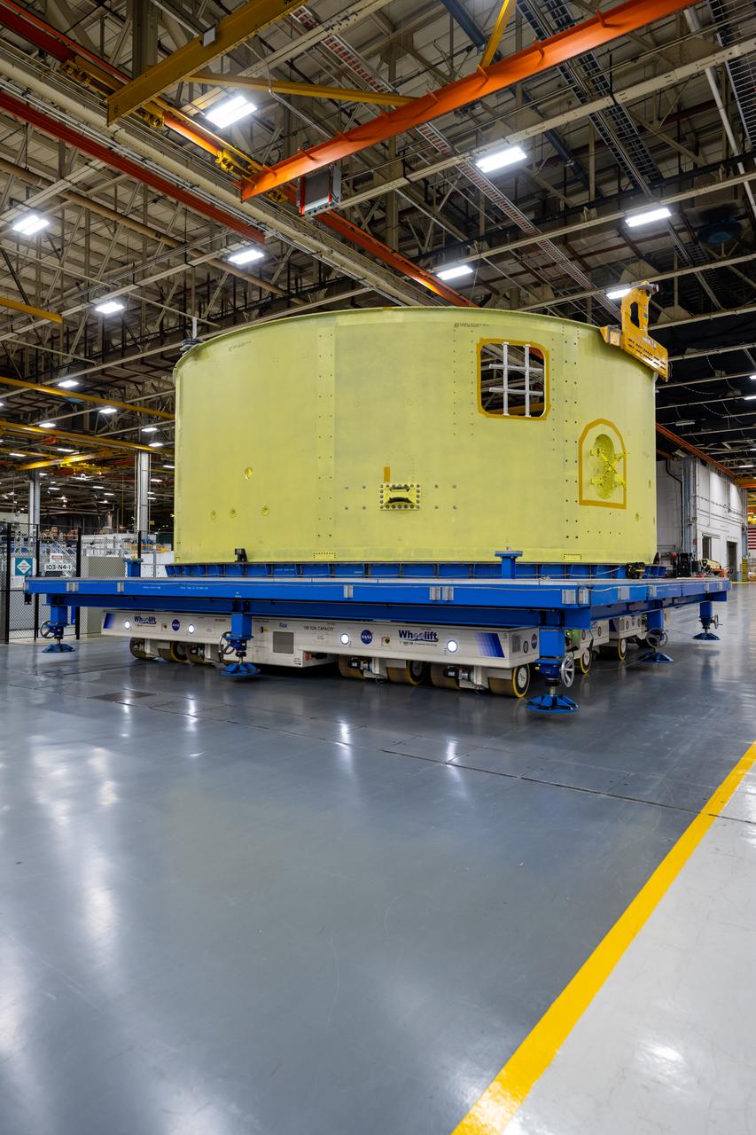
Crews at NASA’s Michoud Assembly Facility in New Orleans move the forward skirt of NASA’s Space Launch System (SLS) rocket to another part of the facility Dec. 15. Teams are preparing to apply the thermal protection system to the flight hardware, which will protect it from the extreme temperatures during launch and flight. The forward skirt is part of the core stage that will power the SLS rocket for the Artemis III mission. The forward skirt houses flight computers, cameras, and avionics.. The SLS core stage is made up of five unique elements: the forward skirt, liquid oxygen tank, intertank, liquid hydrogen tank, and the engine section. When fully stacked, the forward skirt is located at the top of the core stage and connects the stage to the upper part of the rocket. Together with its four RS-25 engines, the rocket’s massive 212-foot-tall core stage — the largest stage NASA has ever built — and its twin solid rocket boosters produce 8.8 million pounds of thrust to send NASA’s Orion spacecraft, astronauts and supplies beyond Earth’s orbit to the Moon and, ultimately, Mars. Offering more payload mass, volume capability and energy to speed missions through space, the SLS rocket, along with NASA’s Gateway in lunar orbit, the Human Landing System, and Orion spacecraft, is part of NASA’s backbone for deep space exploration and the Artemis lunar program. No other rocket is capable of carrying astronauts in Orion around the Moon in a single mission.
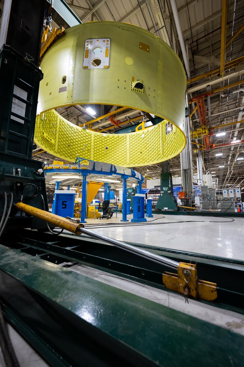
Crews at NASA’s Michoud Assembly Facility in New Orleans move the forward skirt of NASA’s Space Launch System (SLS) rocket to another part of the facility Dec. 15. Teams are preparing to apply the thermal protection system to the flight hardware, which will protect it from the extreme temperatures during launch and flight. The forward skirt is part of the core stage that will power the SLS rocket for the Artemis III mission. The forward skirt houses flight computers, cameras, and avionics.. The SLS core stage is made up of five unique elements: the forward skirt, liquid oxygen tank, intertank, liquid hydrogen tank, and the engine section. When fully stacked, the forward skirt is located at the top of the core stage and connects the stage to the upper part of the rocket. Together with its four RS-25 engines, the rocket’s massive 212-foot-tall core stage — the largest stage NASA has ever built — and its twin solid rocket boosters produce 8.8 million pounds of thrust to send NASA’s Orion spacecraft, astronauts and supplies beyond Earth’s orbit to the Moon and, ultimately, Mars. Offering more payload mass, volume capability and energy to speed missions through space, the SLS rocket, along with NASA’s Gateway in lunar orbit, the Human Landing System, and Orion spacecraft, is part of NASA’s backbone for deep space exploration and the Artemis lunar program. No other rocket is capable of carrying astronauts in Orion around the Moon in a single mission.