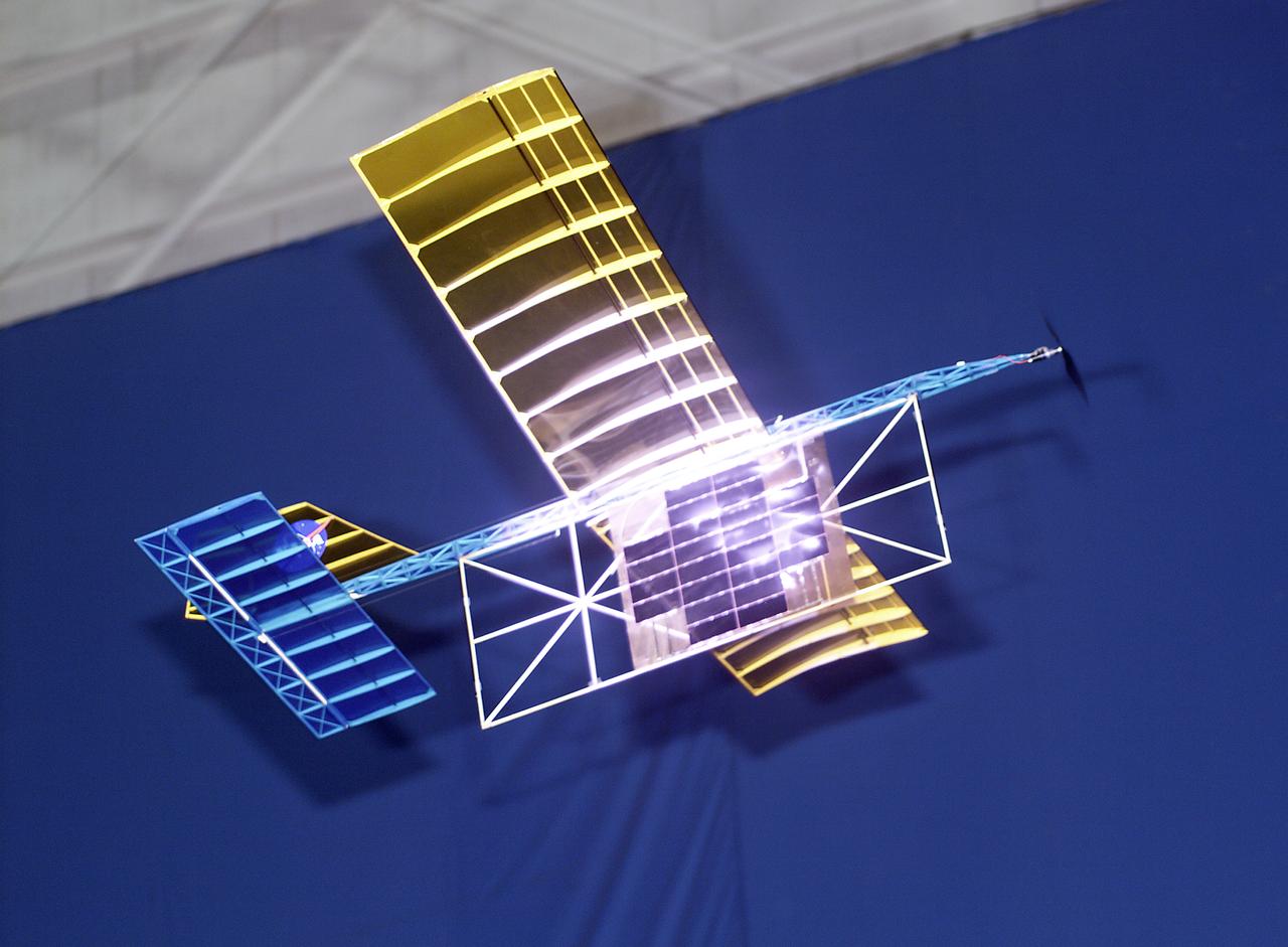
With a laser beam centered on its panel of photovoltaic cells, a lightweight model plane makes the first flight of an aircraft powered by a laser beam inside a building at NASA Marshall Space Flight Center.
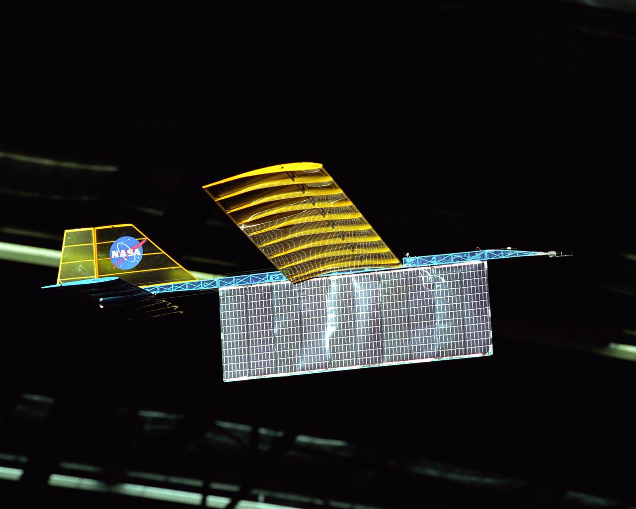
An experimental radio-controlled model aircraft is seen here in flight, powered only by light energy beamed to it by a spotlight.
An experimental radio-controlled model aircraft is seen here in flight powered only by light energy beamed to it by a spotlight.
Powered by a laser beam directed at it from a center pedestal, a lightweight model plane makes the first flight of an aircraft powered by laser energy inside a building at NASA's Marshall Space Flight Center.
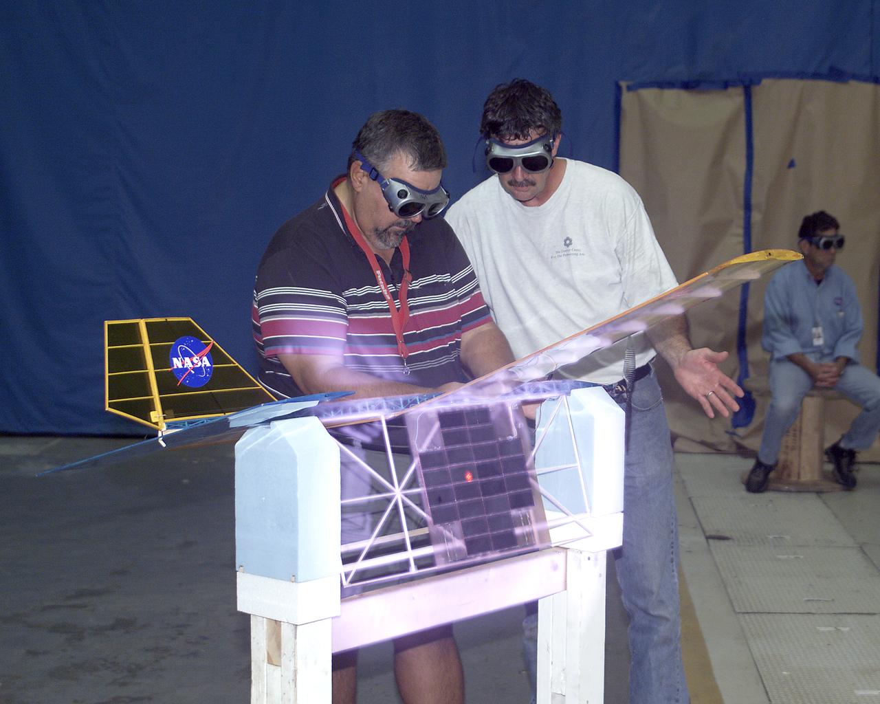
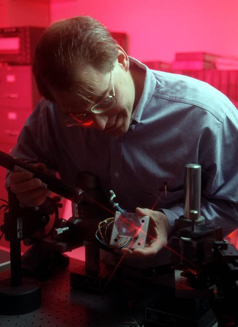
With a laser beam centered on its solar panel, a lightweight model aircraft is checked out by technician Tony Frakowiak and researcher Tim Blackwell before its power-beamed demonstration flight.

NASA’s Beaming Energy for Air Mobility team successfully completed a first-of-its-kind power beaming test at NASA Glenn on June 4, 2025. Later this year, the tested transmitter will be used in a demonstration to wirelessly transmit power using microwaves to a custom power receiver — a step toward gap-filling technology that could one day deliver power on the surface of the Moon or Mars. Seth Waldstein, Seth Schisler and Bryan Schoenholz are in the control room reviewing the results.
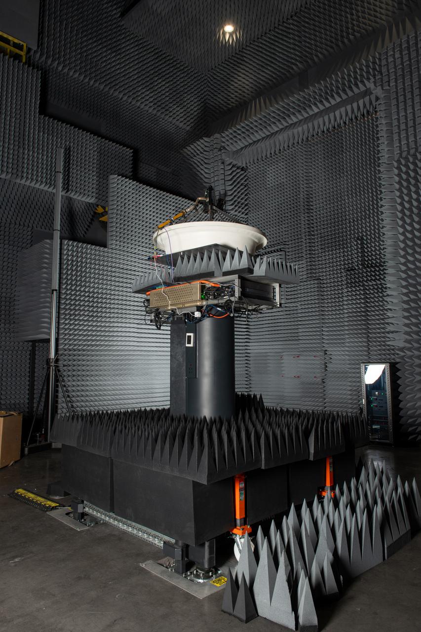
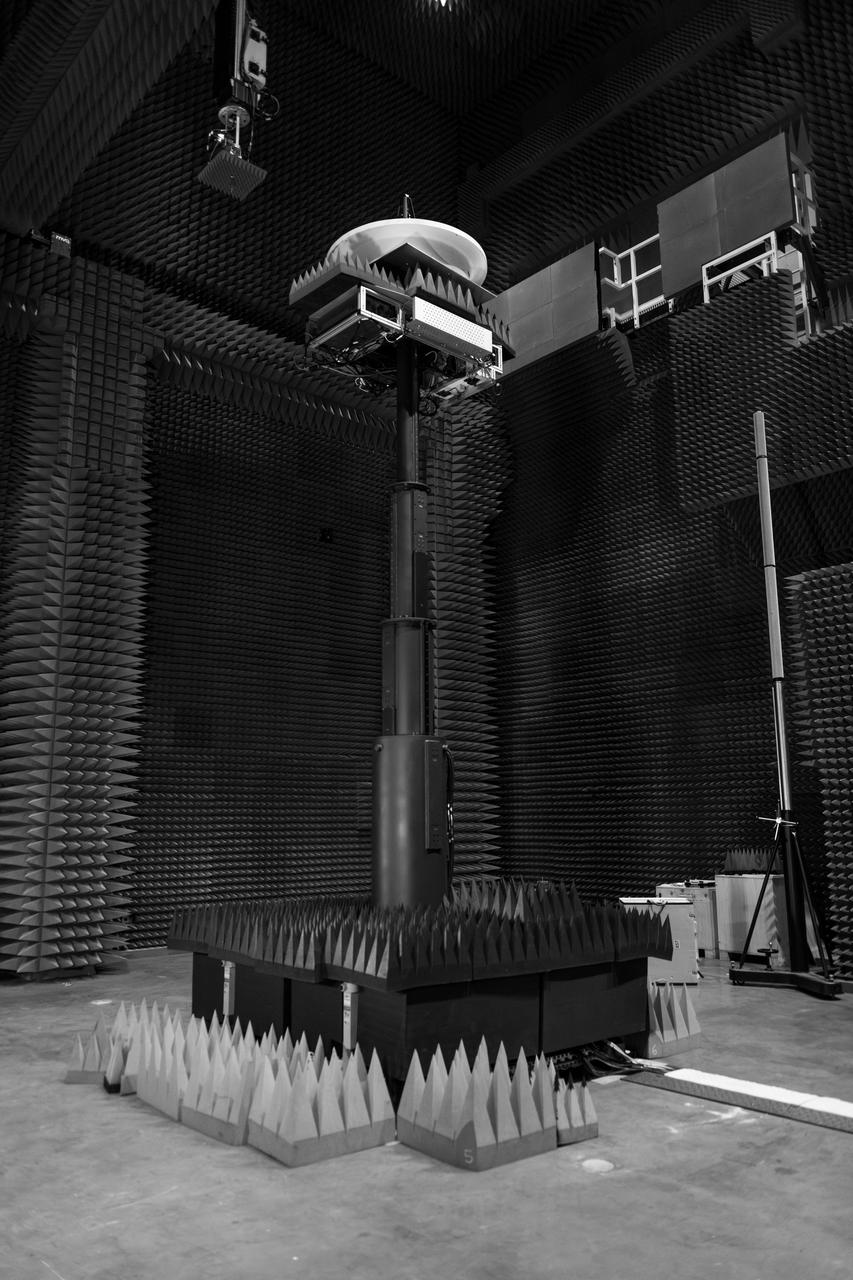
NASA’s Beaming Energy for Air Mobility team successfully completed a first-of-its-kind power beaming test at NASA Glenn on June 4, 2025. Later this year, the tested transmitter will be used in a demonstration to wirelessly transmit power using microwaves to a custom power receiver — a step toward gap-filling technology that could one day deliver power on the surface of the Moon or Mars.
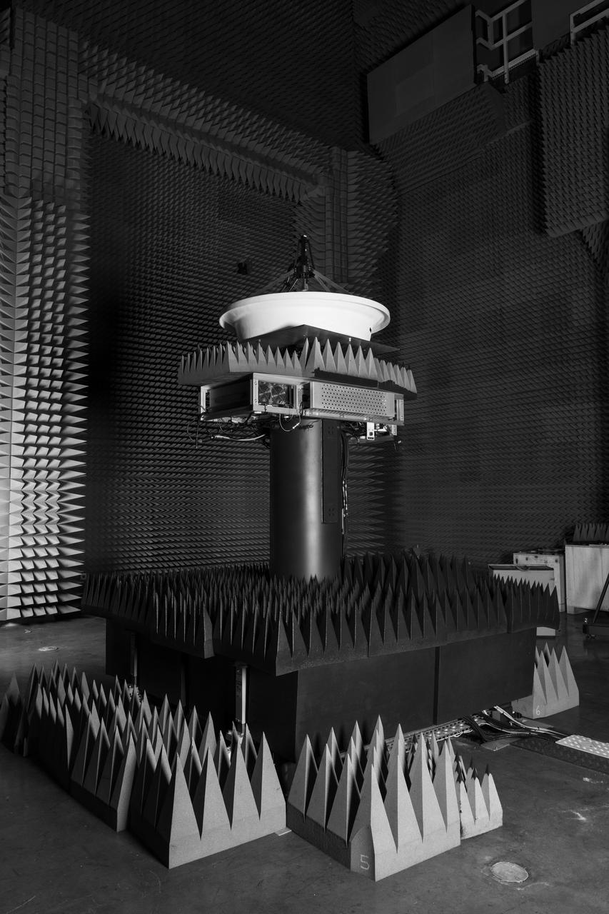
NASA’s Beaming Energy for Air Mobility team successfully completed a first-of-its-kind power beaming test at NASA Glenn on June 4, 2025. Later this year, the tested transmitter will be used in a demonstration to wirelessly transmit power using microwaves to a custom power receiver — a step toward gap-filling technology that could one day deliver power on the surface of the Moon or Mars.
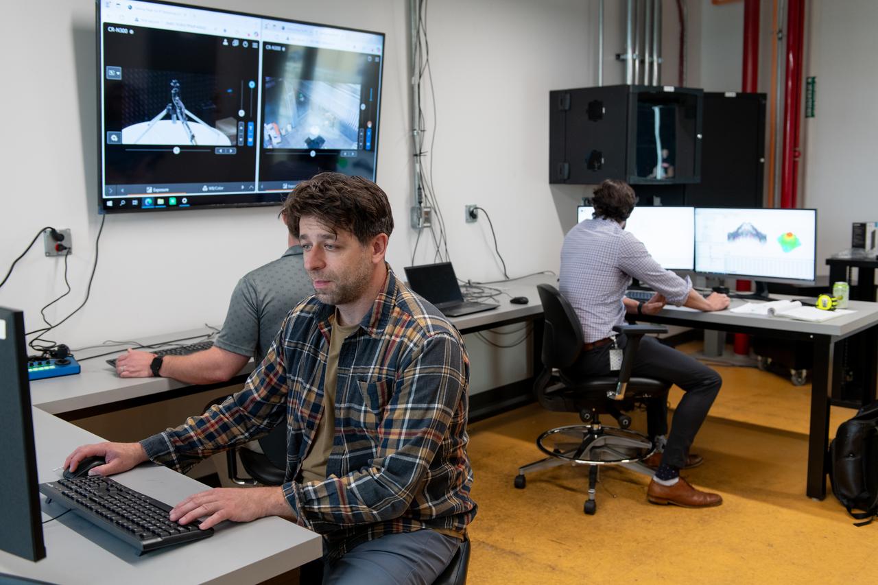
NASA’s Beaming Energy for Air Mobility team successfully completed a first-of-its-kind power beaming test at NASA Glenn. Later this year, the tested transmitter will be used in a demonstration to wirelessly transmit power using microwaves to a custom power receiver — a step toward gap-filling technology that could one day deliver power on the surface of the Moon or Mars. Seth Waldstein, Seth Schisler and Bryan Schoenholz are in the control room reviewing the data.
NASA’s Beaming Energy for Air Mobility team successfully completed a first-of-its-kind power beaming test at NASA Glenn on June 4, 2025. Later this year, the tested transmitter will be used in a demonstration to wirelessly transmit power using microwaves to a custom power receiver — a step toward gap-filling technology that could one day deliver power on the surface of the Moon or Mars.
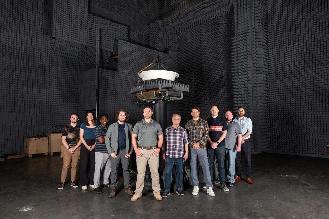
NASA’s Beaming Energy for Air Mobility team successfully completed a first-of-its-kind power beaming test at NASA Glenn on June 4, 2025. Later this year, the tested transmitter will be used in a demonstration to wirelessly transmit power using microwaves to a custom power receiver — a step toward gap-filling technology that could one day deliver power on the surface of the Moon or Mars. Pictured from left to right are Hayden Klopp, Rebecca Buehrle, Kerry Johnson, Avery Brock, Seth Schisler, Vladimir Volman, Seth Waldstein, David Rinehart, Rocco Viggiano, and Donald Dornbusch.

An experimental radio-controlled model aircraft is seen here in flight powered only by light energy beamed to it by a spotlight.
The SELENE Optics project was designed to send powerful laser beams into space to repower satellites and to recharge their batteries, as well as sending laser beams to the moon for the same purpose instead of relying on solar power. This project also was intended to be used for repowering extended space flights.
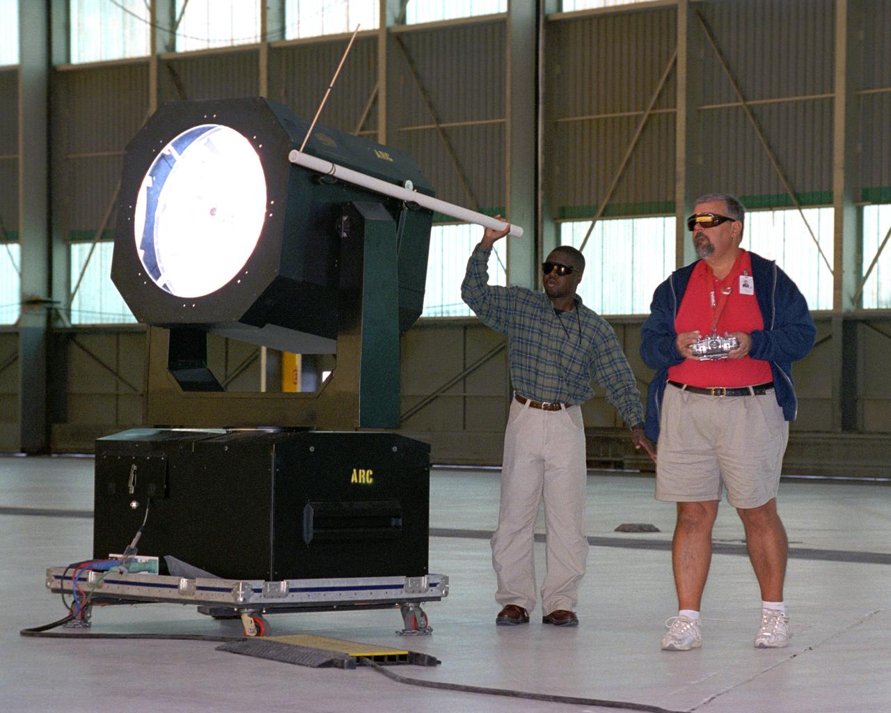
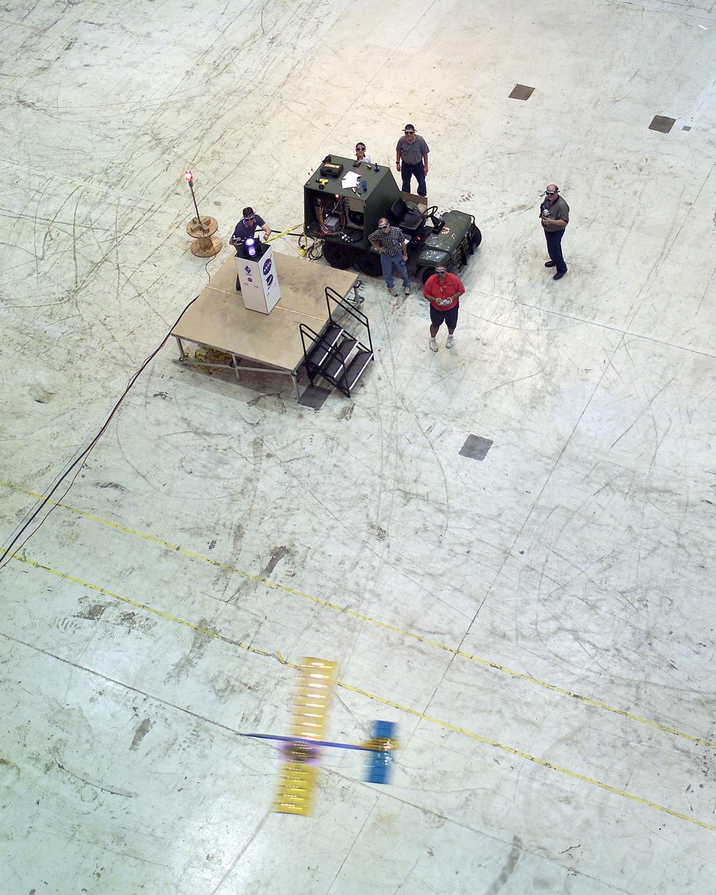
Dryden Model Shop's Tony Frakowiak remotely flies an experimental model aircraft being powered by a spotlight operated by Dryden aerospace engineer (code RA) Ryan Warner.
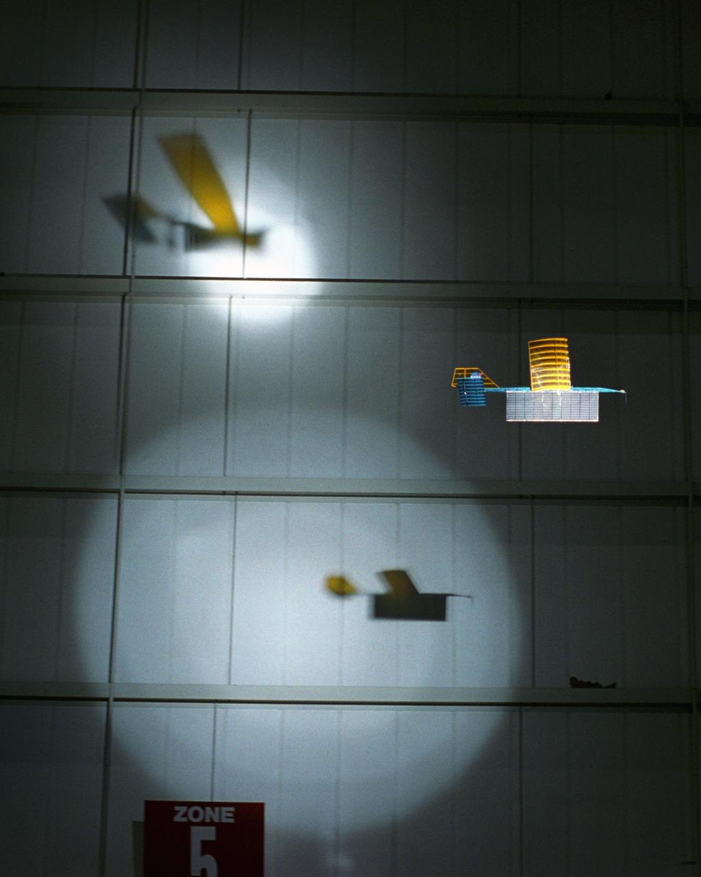
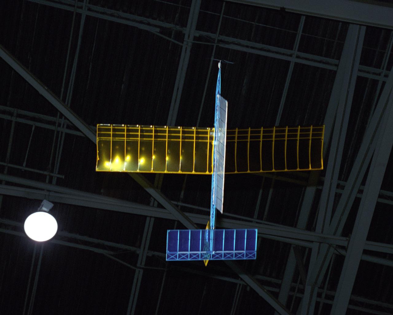
An experimental radio-controlled model aircraft casts two unique shadows as it flies inside a Dryden hangar using two spotlights as energy sources. This phase of testing was used to develop procedures and operations for "handing off" the aircraft between different sources of power.
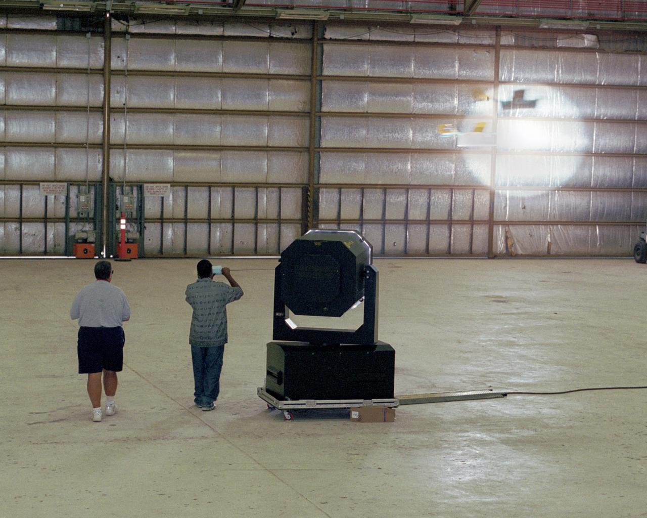
Dryden Model Shop's Tony Frakowiak remotely flies an experimental model aircraft being powered by a spotlight operated by student intern Derrick Barrett.
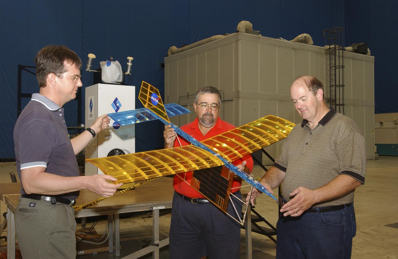
A team of NASA researchers from Marshall Space Flight Center (MSFC) and Dryden Flight Research center have proven that beamed light can be used to power an aircraft, a first-in-the-world accomplishment to the best of their knowledge. Using an experimental custom built radio-controlled model aircraft, the team has demonstrated a system that beams enough light energy from the ground to power the propeller of an aircraft and sustain it in flight. Special photovoltaic arrays on the plane, similar to solar cells, receive the light energy and convert it to electric current to drive the propeller motor. In a series of indoor flights this week at MSFC, a lightweight custom built laser beam was aimed at the airplane `s solar panels. The laser tracks the plane, maintaining power on its cells until the end of the flight when the laser is turned off and the airplane glides to a landing. The laser source demonstration represents the capability to beam more power to a plane so that it can reach higher altitudes and have a greater flight range without having to carry fuel or batteries, enabling an indefinite flight time. The demonstration was a collaborative effort between the Dryden Center at Edward's, California, where the aircraft was designed and built, and MSFC, where integration and testing of the laser and photovoltaic cells was done. Laser power beaming is a promising technology for consideration in new aircraft design and operation, and supports NASA's goals in the development of revolutionary aerospace technologies. Photographed with their invention are (from left to right): David Bushman and Tony Frackowiak, both of Dryden; and MSFC's Robert Burdine.
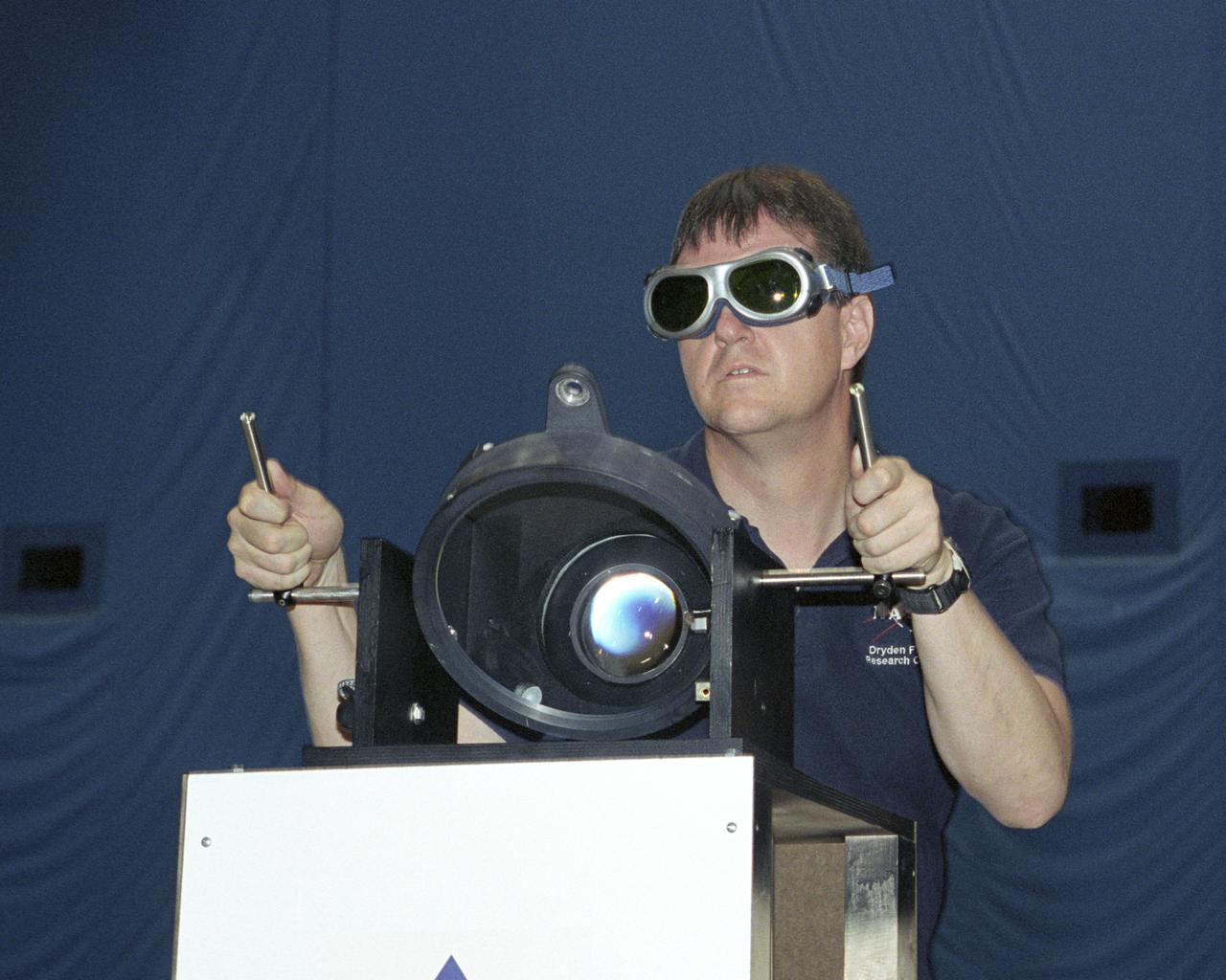
NASA Dryden project engineer Dave Bushman carefully aims the optics of a laser device at a solar cell panel on a model aircraft during the first flight demonstration of an aircraft powered by laser light.
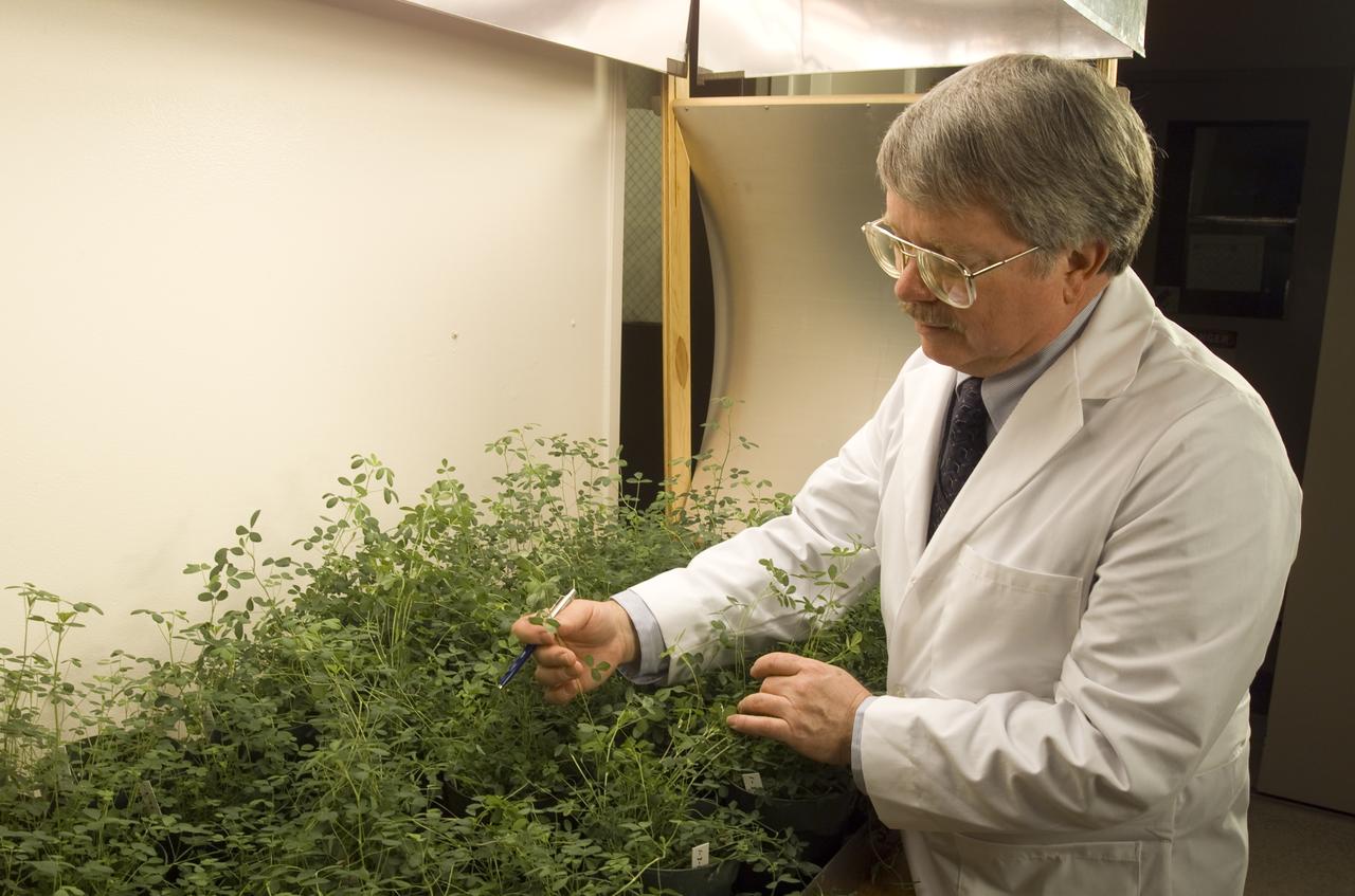
Microvave effects on plant growth (alfalfa), shown here is Dr. Jay Skiles of NASA Ames Research Center, Moffett Field, Calif. NASA scientists are about to test that hypothesis by evaluating the effects of continuously beaming weak microwaves on alfalfa plants during laboratory tests. Microwaves derived from solar power and transmitted by orbiting satellites to electric power stations on Earth may someday enable U.S. energy self-sufficiency, but is this method safe for local plant life?

Microvave effects on plant growth (alfalfa), shown here is Dr. Jay Skiles of NASA Ames Research Center, Moffett Field, Calif. NASA scientists are about to test that hypothesis by evaluating the effects of continuously beaming weak microwaves on alfalfa plants during laboratory tests. Microwaves derived from solar power and transmitted by orbiting satellites to electric power stations on Earth may someday enable U.S. energy self-sufficiency, but is this method safe for local plant life?

Looking like an alien space ship or a flying saucer the Microwave Lightcraft is an unconventional launch vehicle approach for delivering payload to orbit using power transmitted via microwaves. Microwaves re beamed from either a ground station or an orbiting solar power satellite to the lightcraft. The energy received breaks air molecules into a plasma and a magnetohydrodynamic fanjet provides the lifting force. Only a small amount of propellant is required for circulation, attitude control and deorbit.
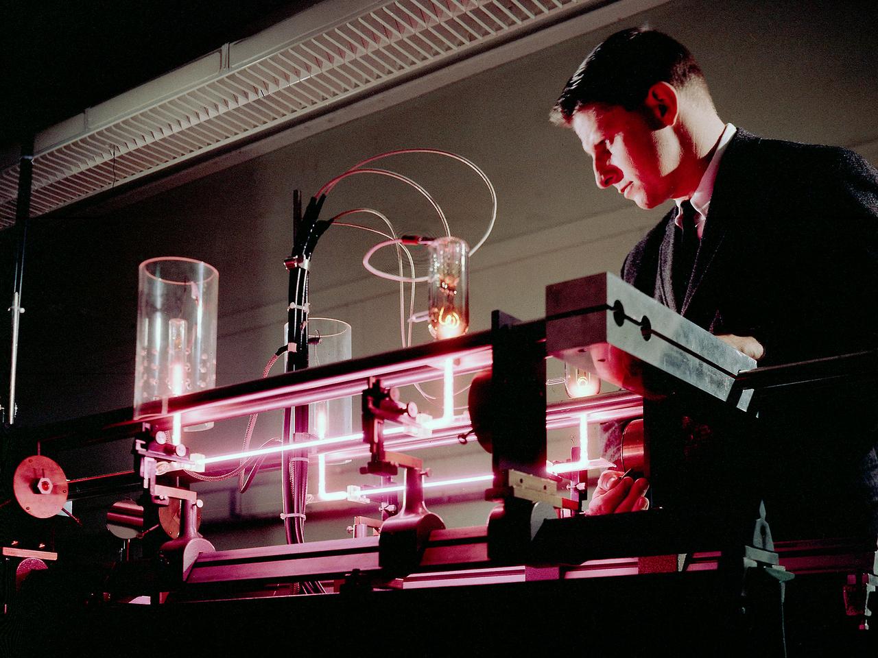
Richard Lancashire operates a gas laser interferometer in the Electric Conversion Laboratory at the National Aeronautics and Space Administration (NASA) Lewis Research Center. Lewis was in the midst of a long-term effort to develop methods of delivering electrical power to spacecraft using nuclear, solar, or electrochemical technologies. Lancashire was measuring the thermionic diode’s plasma particle density. The thermionic diodes were being studied for possible use in radioisotope thermoelectric generators for use in space. Microwave interferometry was one method of measuring transient plasmas. The interferometer measured the difference between the frequencies of two laser beams, one of which passed through the diode. The electron density was measured by revealing the phase shift of the transmitted microwave beam brought about by a change in the plasma refraction. Microwave interferometry, however, offers poor spatial resolution and has limited range of applicability.
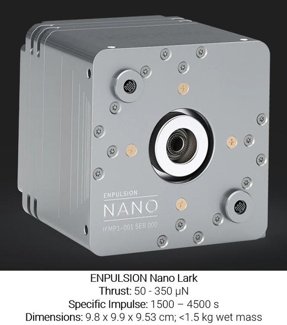
jsc2025e076915 (September 25, 2025) -- This is the ENPULSION Nano Lark thruster, a unit that contains its own power, propellant, and ion beam systems. While this thruster is not tested on station, the MICATOS investigation observes how molten indium behaves in microgravity, which could improve future thrusters of this type and refine methods for in-space soldering. Image courtesy of Enpulsion.
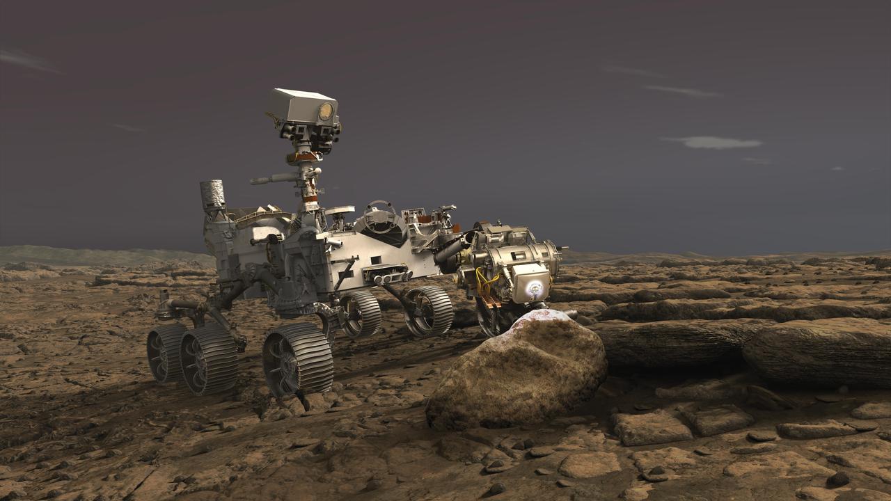
In this illustration, NASA's Perseverance rover uses its Planetary Instrument for X-ray Lithochemistry (PIXL) instrument to analyze a rock on the surface of Mars. PIXL uses a focused X-ray beam to analyze the chemistry of features as small as a grain of sand. The tiny but powerful beam causes rocks to fluoresce, or produce a glow. While the glow is invisible to the human eye, it is detectable by the instrument and varies according to the rock's elemental chemistry. PIXL scan the beam across the surface of the rock to produce a postage-stamp-sized map of the rock's chemistry at the end of an overnight scan. PIXL also has an optical fiducial system (OFS) that includes white "flood lights" — seen on the rock in this artist's concept — that is used together with a pattern of red lasers to illuminate the rock while its camera captures images of the mapped area. The pictures are used for multiple purposes: PIXL analyzes them on board to work out where the target is — in 3D — and move itself into the right position for science collection and the safety of the instrument. The pictures are also downlinked to Earth so scientists can see exactly where each measurement was taken. This allows scientists to tie chemistry accurately to rock texture, which helps them to determine how these features formed and whether they were biological in nature. https://photojournal.jpl.nasa.gov/catalog/PIA23719
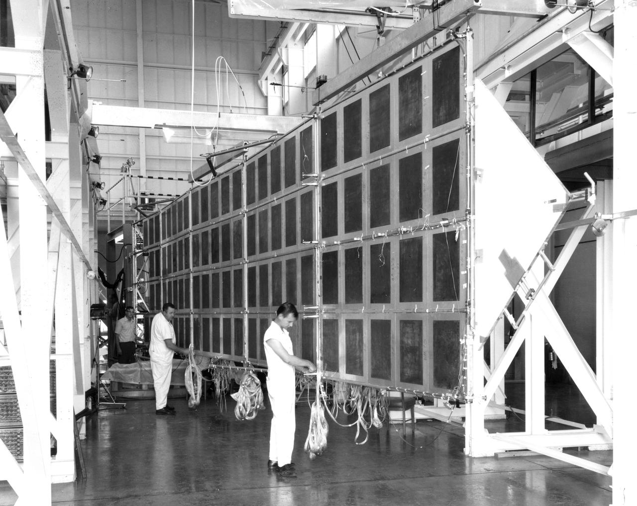
Technicians at NASA’s Marshall Space Flight Center check the wiring on a mechanical test article of the Apollo Telescope Mount (ATM) solar array. Four such arrays were joined in a cross to provide electric power for the ATM in Earth orbit. The deployment mechanism for extending the wing to the fully open position had just been tested when this photograph was taken. The array was suspended from beams riding on air bearings to closely simulate the weightless conditions under which it would be deployed in space. The wings are folded against the sides of the ATM for launch and are deployed by a scissors mechanism in Earth’s orbit.
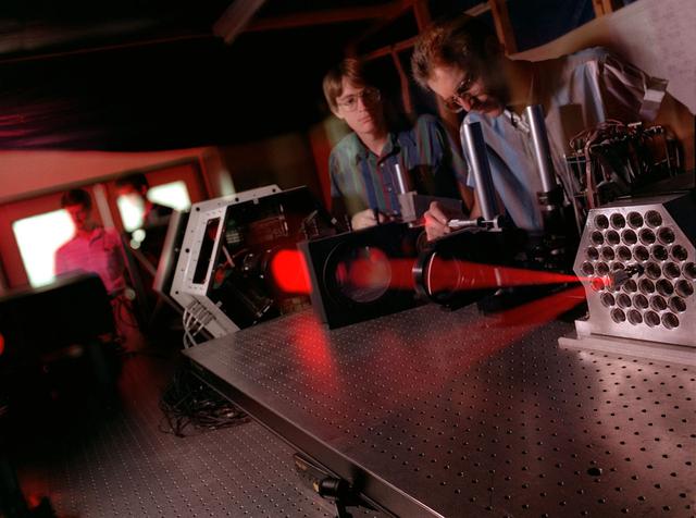
Scientists at Marshall's Adaptive Optics Lab demonstrate the Wave Front Sensor alignment using the Phased Array Mirror Extendible Large Aperture (PAMELA) optics adjustment. The primary objective of the PAMELA project is to develop methods for aligning and controlling adaptive optics segmented mirror systems. These systems can be used to acquire or project light energy. The Next Generation Space Telescope is an example of an energy acquisition system that will employ segmented mirrors. Light projection systems can also be used for power beaming and orbital debris removal. All segmented optical systems must be adjusted to provide maximum performance. PAMELA is an on going project that NASA is utilizing to investigate various methods for maximizing system performance.
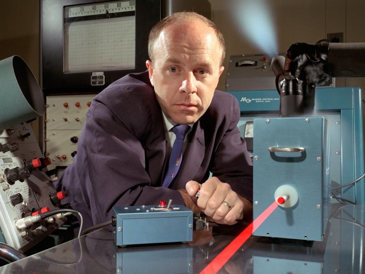
National Aeronautics and Space Administration (NASA) Lewis Research Center researcher Americo Forestieri aims a ruby laser beam at a crystal to determine the effects of its radiation. Forestieri was a researcher in the Electric Component Experiment Section of the Space Power System Division. Lewis was in the midst of a long-term effort to develop methods of delivering electrical power to spacecraft using nuclear, solar, or electrochemical technologies. Ruby lasers contain a ruby crystal with mirrors on either side. The laser action is created when a high-intensity lamp shines around the ruby and excites the electrons in the ruby’s chromium atoms. After the excitation, the electrons emit their ruby-red light. The mirrors reflect some of this red light back and forth inside the ruby which causes other excited chromium atoms to produce additional red light. This continues until the light pulse reaches high power levels and consumes all of the energy stored in the crystal. Forestieri used optical absorption and electron paramagnetic resonance techniques to study the extent and manner in which the radiation interacted with the samples. He determined that individual bands were assigned to specific electronic transitions. He also studied the atomic changes in the ruby crystals after irradiation. He found that complex interactions depend on the crystal pretreatment, purity, and irradiation dose.
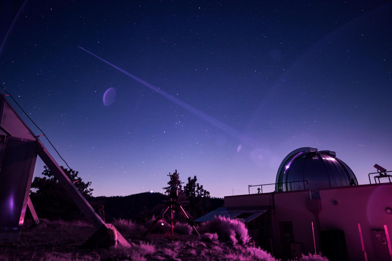
In this infrared photograph, the Optical Communications Telescope Laboratory (OCTL) at NASA Jet Propulsion Laboratory's Table Mountain Facility near Wrightwood, California, beams its eight-laser beacon (at a total power of 1.4 kilowatts) to the Deep Space Optical Communications (DSOC) flight laser transceiver aboard NASA's Psyche spacecraft. The photo was taken on June 2, 2025, when Psyche was about 143 million miles (230 million kilometers) from Earth. The faint purple crescent just left of center and near the laser beam is a lens flare caused by a bright light (out of frame) reflecting inside the camera lens. As the experiment's ground laser transmitter, OCTL transmits at an infrared wavelength of 1,064 nanometers from its 3.3-foot-aperture (1-meter) telescope. The telescope can also receive faint infrared photons (at a wavelength of 1,550 nanometers) from the 4-watt flight laser transceiver on Psyche. Neither infrared wavelength is easily absorbed or scattered by Earth's atmosphere, making both ideal for deep space optical communications. To receive the most distant signals from Psyche, the project enlisted the powerful 200-inch-aperture (5-meter) Hale Telescope at Caltech's Palomar Observatory in San Diego County, California, as its primary downlink station, which provided adequate light-collecting area to capture the faintest photons. Those photons were then directed to a cryogenically cooled superconducting high-efficiency detector array at the observatory where the information encoded in the photons could be processed. Managed by JPL, DSOC was designed to demonstrate that data encoded in laser photons could be reliably transmitted, received, and then decoded after traveling millions of miles from Earth out to Mars distances. Nearly two years after launching aboard the agency's Psyche mission in 2023, the demonstration completed its 65th and final "pass" on Sept. 2, 2025, sending a laser signal to Psyche and receiving the return signal from 218 million miles (350 million kilometers) away. https://photojournal.jpl.nasa.gov/catalog/PIA26661
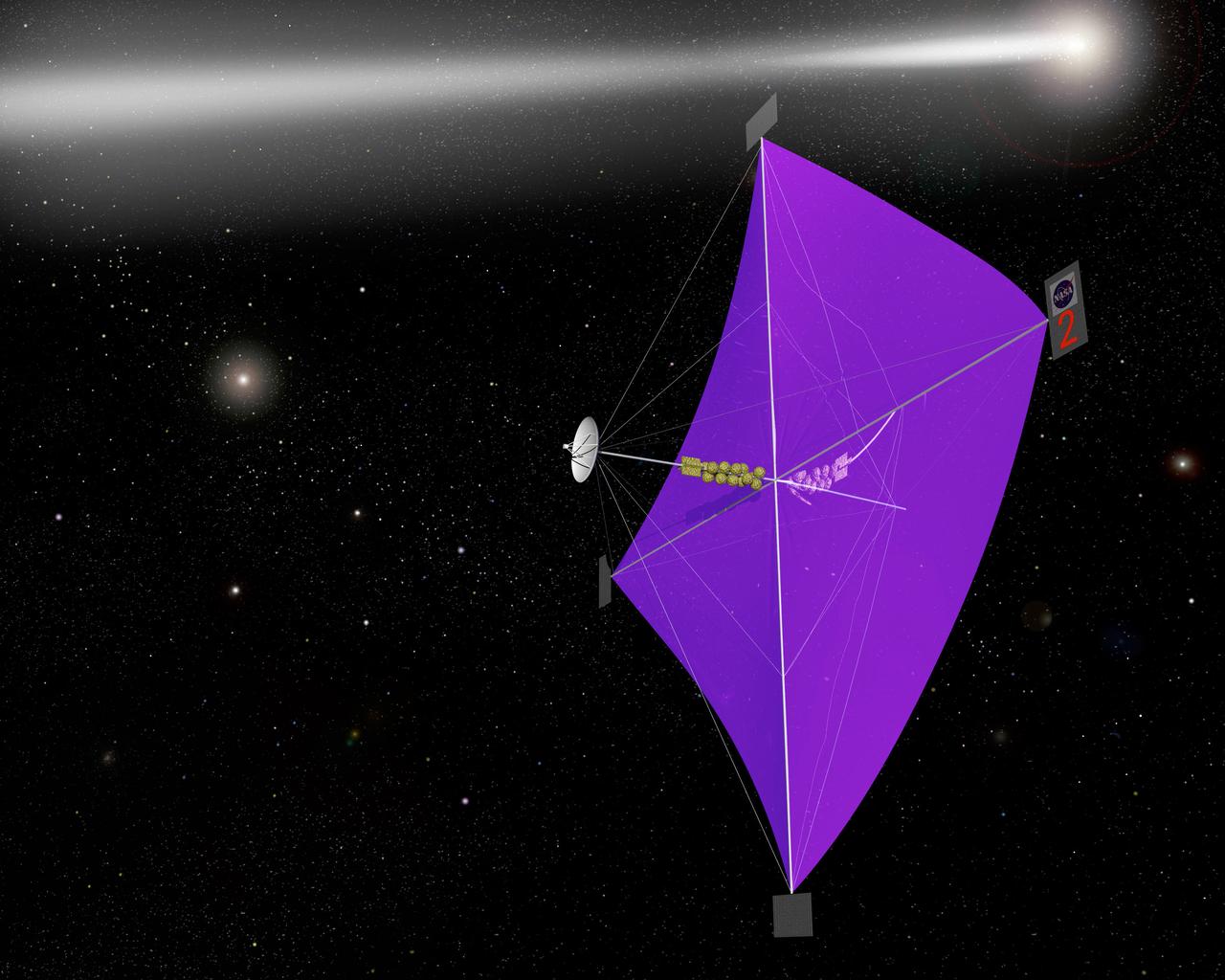
Engineers at Marshall Space Flight Center's Interstellar Propulsion Research department are proposing different solutions to combustion propellants for future space travel. Pictured here is one alternative, the solar sail, depicted through an artist's concept. The idea is, once deployed, the sail will allow solar winds to propel a spacecraft away from Earth and towards its destination. This would allow a spacecraft to travel indefinitely without the need to refuel during its prolong journey. Thin reflective sails could be propelled through space by sunlight, microwave beams, or laser beams, just as the wind pushes sailboats on Earth. The sail will be the largest spacecraft ever built, sparning 440 yards, twice the diameter of the Louisiana Super Dome. Construction materials are being tested in a simulated space environment, where they are exposed to harsh conditions to test their performance and durability in extremely hot and cold temperatures. A leading candidate for the construction material is a carbon fiber material whose density is less than 1/10 ounce per square yard, the equivalent of flattening one raisin to the point that it covers a square yard. In space, the material would unfurl like a fan when it is deployed from an expendable rocket. Mankind's first venture outside of our solar system is proposed for launch in a 2010 timeframe. An interstellar probe, powered by the fastest spacecraft ever flown, will zoom toward the stars at 58 miles per second. It will cover the distance from New York to Los Angeles in less than a minute and will travel over 23 billion miles beyond the edge of the solar system.
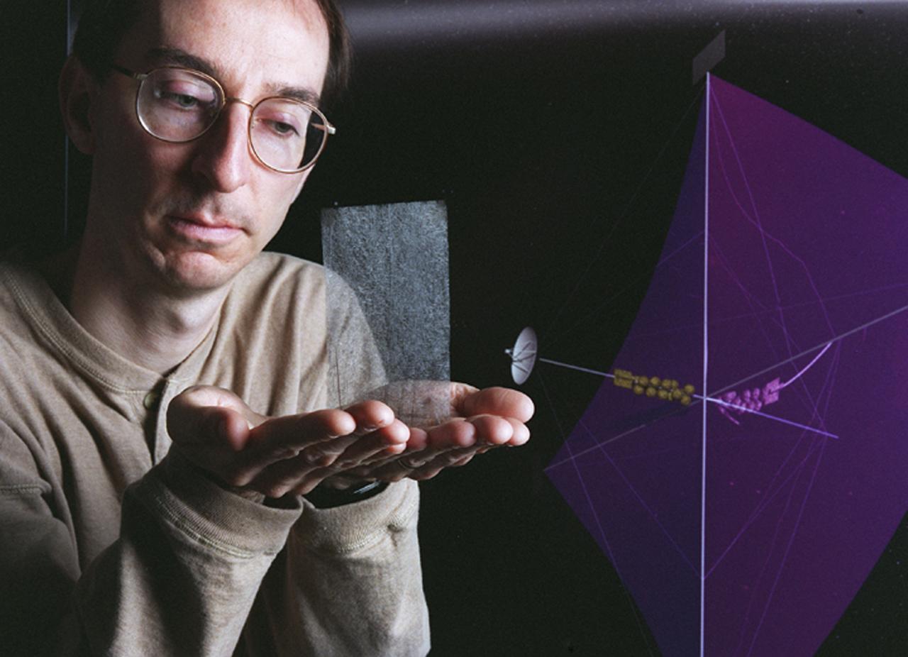
Engineers at Marshall Space Flight Center's (MSFC) Interstellar Propulsion Research department are proposing different solutions to combustion propellants for future space travel. One alternative being tested is the solar sail. The idea is, once deployed, the sail will allow solar winds to propel a spacecraft away from Earth and towards its destination. This would allow a spacecraft to travel indefinitely without the need to refuel during its ong journey. Thin reflective sails could be propelled through space by sunlight, microwave beams, or laser beams, just as the wind pushes sailboats on Earth. The sail will be the largest spacecraft ever built, sparning 440 yards, twice the diameter of the Louisiana Super Dome. Construction materials are being tested in a simulated space environment, where they are exposed to harsh conditions to test their performance and durability in extremely hot and cold temperatures. A leading candidate for the construction material is a carbon fiber material whose density is less than 1/10 ounce per square yard, the equivalent of flattening one raisin to the point that it covers a square yard. In space, the material would unfurl like a fan when it is deployed from an expendable rocket. This photo shows Les Johnson, manager of MSFC's Interstellar Propulsion Research Center holding the rigid, lightweight carbon fiber. An artist's concept of the sail is on the right. Mankind's first venture outside of our solar system is proposed for launch in a 2010 timeframe. An interstellar probe, powered by the fastest spacecraft ever flown, will zoom toward the stars at 58 miles per second. It will cover the distance from New York to Los Angeles in less than a minute and will travel over 23 billion miles beyond the edge of the solar system.
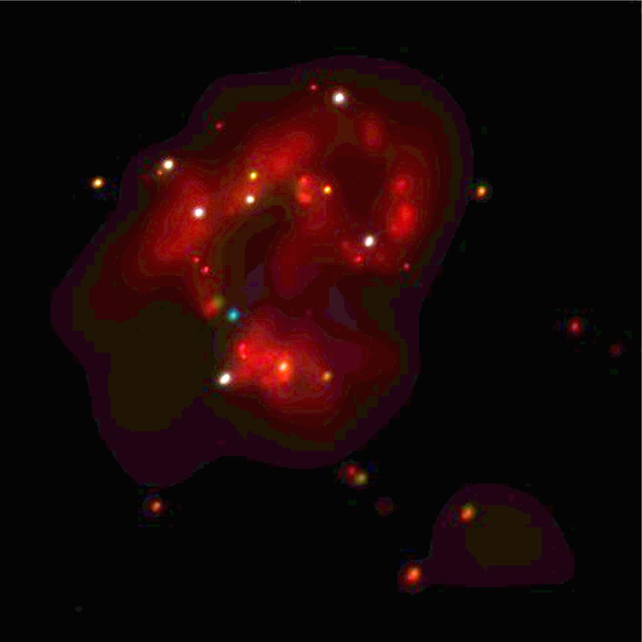
This Chandra image shows the central regions of two colliding galaxies known collectively as the Antennae (NGC-4038/4039). The Chandra image reveals a large population of extremely bright x-ray sources in this area of intense star formation. These x-ray sources, which emit 10 to several hundred times more x-ray power than similar sources in our own galaxy, are believed to be either massive black holes, or black holes that are beaming their energy toward Earth. In this x-ray image, red represents the low energy band, green intermediate, and blue the highest observed energies. The white and yellow sources are those that emit significant amounts of both low and high energy x-rays. About 60 million light years from Earth in the constellation Corvus, the Antennae Galaxies got their nickname from the wispy anntennae-like streams of gas as seen by optical telescopes. These ongoing wisps are believed to have been produced approximately 100 million years ago by the collision between the gala
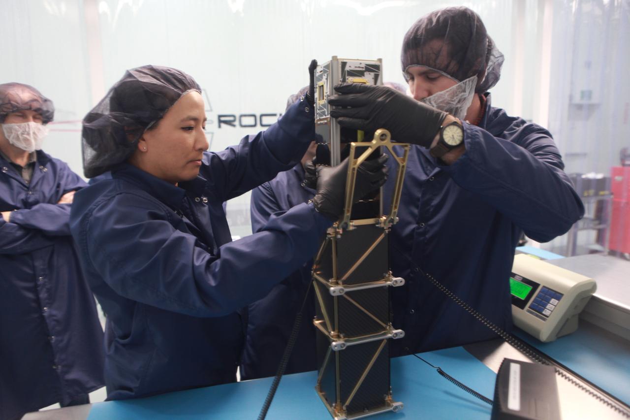
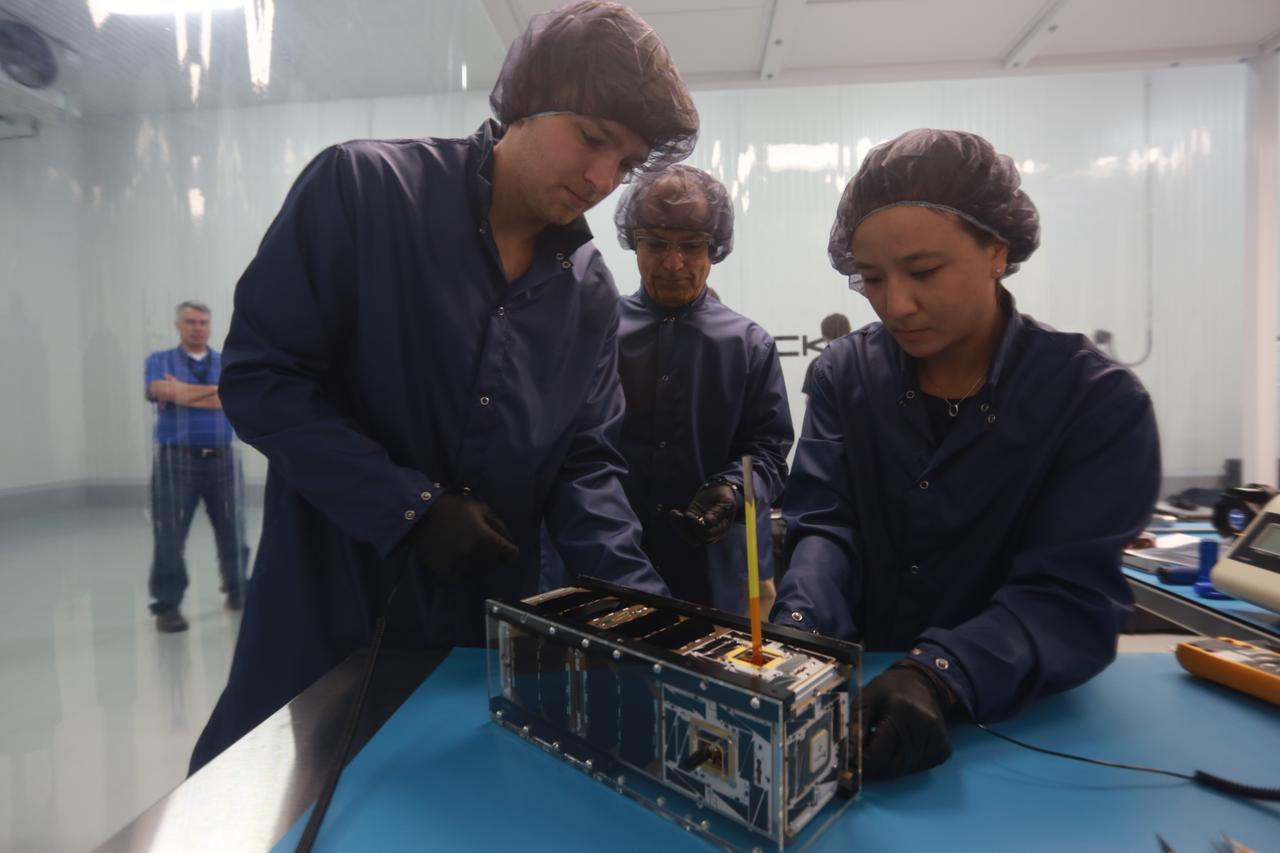
The goal of the CHOMPTT mission is to demonstrate new technologies that could be used for navigation and satellite networking in deep space. For future explorers and colonizers of the Moon or Mars, navigation systems like GPS here on Earth, will be essential. The key idea behind CHOMPTT is to use lasers to transfer time code data over long distances instead of radio waves. Because lasers can be more tightly beamed compared to radio waves, more of the transmitted energy reaches its intended target, making them more power-efficient. CHOMPTT takes advantage of this and of new miniature but very stable atomic clocks to produce a timing system with performance similar to that of GPS, but in a very compact and power efficient form factor. We will use a pulsed laser system, located at the Kennedy Space Center that will be synchronized with an atomic clock. Laser pulses will propagate from the ground to the orbiting CHOMPTT CubeSat and back. By precisely measuring the time of emission and detection of these pulses on the ground and in space we can calculate the time discrepancy between the ground atomic clock and the atomic clock on CHOMPTT. Our goal is to do this with an accuracy of 0.2 billionths of a second, or the time it takes light to travel just 6 centimeters. In the future, we envision using this technology on constellations or swarms of small satellites, for example orbiting the Moon, to equip them with precision navigation, networking, and ranging capabilities. CHOMPTT is a collaboration between the University of Florida and the NASA Ames Research Center. The CHOMPTT precision timing payload was designed and built by the Precision Space Systems Lab at the University of Florida, while the 3U CubeSat bus that has prior flight heritage, was provided by NASA Ames. The CHOMPTT mission has been funded by the Air Force Research Lab and by NASA.
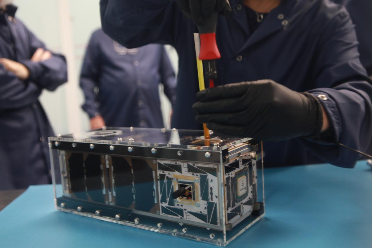
The goal of the CHOMPTT mission is to demonstrate new technologies that could be used for navigation and satellite networking in deep space. For future explorers and colonizers of the Moon or Mars, navigation systems like GPS here on Earth, will be essential. The key idea behind CHOMPTT is to use lasers to transfer time code data over long distances instead of radio waves. Because lasers can be more tightly beamed compared to radio waves, more of the transmitted energy reaches its intended target, making them more power-efficient. CHOMPTT takes advantage of this and of new miniature but very stable atomic clocks to produce a timing system with performance similar to that of GPS, but in a very compact and power efficient form factor. We will use a pulsed laser system, located at the Kennedy Space Center that will be synchronized with an atomic clock. Laser pulses will propagate from the ground to the orbiting CHOMPTT CubeSat and back. By precisely measuring the time of emission and detection of these pulses on the ground and in space we can calculate the time discrepancy between the ground atomic clock and the atomic clock on CHOMPTT. Our goal is to do this with an accuracy of 0.2 billionths of a second, or the time it takes light to travel just 6 centimeters. In the future, we envision using this technology on constellations or swarms of small satellites, for example orbiting the Moon, to equip them with precision navigation, networking, and ranging capabilities. CHOMPTT is a collaboration between the University of Florida and the NASA Ames Research Center. The CHOMPTT precision timing payload was designed and built by the Precision Space Systems Lab at the University of Florida, while the 3U CubeSat bus that has prior flight heritage, was provided by NASA Ames. The CHOMPTT mission has been funded by the Air Force Research Lab and by NASA.
The goal of the CHOMPTT mission is to demonstrate new technologies that could be used for navigation and satellite networking in deep space. For future explorers and colonizers of the Moon or Mars, navigation systems like GPS here on Earth, will be essential. The key idea behind CHOMPTT is to use lasers to transfer time code data over long distances instead of radio waves. Because lasers can be more tightly beamed compared to radio waves, more of the transmitted energy reaches its intended target, making them more power-efficient. CHOMPTT takes advantage of this and of new miniature but very stable atomic clocks to produce a timing system with performance similar to that of GPS, but in a very compact and power efficient form factor. We will use a pulsed laser system, located at the Kennedy Space Center that will be synchronized with an atomic clock. Laser pulses will propagate from the ground to the orbiting CHOMPTT CubeSat and back. By precisely measuring the time of emission and detection of these pulses on the ground and in space we can calculate the time discrepancy between the ground atomic clock and the atomic clock on CHOMPTT. Our goal is to do this with an accuracy of 0.2 billionths of a second, or the time it takes light to travel just 6 centimeters. In the future, we envision using this technology on constellations or swarms of small satellites, for example orbiting the Moon, to equip them with precision navigation, networking, and ranging capabilities. CHOMPTT is a collaboration between the University of Florida and the NASA Ames Research Center. The CHOMPTT precision timing payload was designed and built by the Precision Space Systems Lab at the University of Florida, while the 3U CubeSat bus that has prior flight heritage, was provided by NASA Ames. The CHOMPTT mission has been funded by the Air Force Research Lab and by NASA.

This is a composite image of Uranus by Voyager 2 and two different observations made by Hubble — one for the ring and one for the auroras. Ever since Voyager 2 beamed home spectacular images of the planets in the 1980s, planet-lovers have been hooked on auroras on other planets. Auroras are caused by streams of charged particles like electrons that come from various origins such as solar winds, the planetary ionosphere, and moon volcanism. They become caught in powerful magnetic fields and are channeled into the upper atmosphere, where their interactions with gas particles, such as oxygen or nitrogen, set off spectacular bursts of light. The auroras on Jupiter and Saturn are well-studied, but not much is known about the auroras of the giant ice planet Uranus. In 2011, the NASA/ESA Hubble Space Telescope became the first Earth-based telescope to snap an image of the auroras on Uranus. In 2012 and 2014 a team led by an astronomer from Paris Observatory took a second look at the auroras using the ultraviolet capabilities of the Space Telescope Imaging Spectrograph (STIS) installed on Hubble. They tracked the interplanetary shocks caused by two powerful bursts of solar wind traveling from the sun to Uranus, then used Hubble to capture their effect on Uranus’ auroras — and found themselves observing the most intense auroras ever seen on the planet. By watching the auroras over time, they collected the first direct evidence that these powerful shimmering regions rotate with the planet. They also re-discovered Uranus’ long-lost magnetic poles, which were lost shortly after their discovery by Voyager 2 in 1986 due to uncertainties in measurements and the featureless planet surface. Credit: ESA/Hubble & NASA, L. Lamy / Observatoire de Paris <b><a href="http://www.nasa.gov/audience/formedia/features/MP_Photo_Guidelines.html" rel="nofollow">NASA image use policy.</a></b> <b><a href="http://www.nasa.gov/centers/goddard/home/index.html" rel="nofollow">NASA Goddard Space Flight Center</a></b> enables NASA’s mission through four scientific endeavors: Earth Science, Heliophysics, Solar System Exploration, and Astrophysics. Goddard plays a leading role in NASA’s accomplishments by contributing compelling scientific knowledge to advance the Agency’s mission. <b>Follow us on <a href="http://twitter.com/NASAGoddardPix" rel="nofollow">Twitter</a></b> <b>Like us on <a href="http://www.facebook.com/pages/Greenbelt-MD/NASA-Goddard/395013845897?ref=tsd" rel="nofollow">Facebook</a></b> <b>Find us on <a href="http://instagrid.me/nasagoddard/?vm=grid" rel="nofollow">Instagram</a></b>
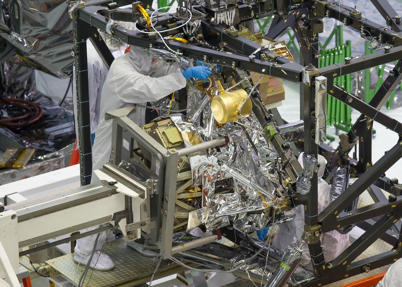
A technician is installing the bolts that will hold the MIRI, or Mid-Infrared Instrument, to the composite Integrated Science Instrument Module (ISIM) structure, or the black frame. The MIRI is attached to a balance beam, called the Horizontal Integration Tool (HIT), hanging from a precision overhead crane. That's the same tool that Hubble engineers used to prepare hardware for its servicing missions. Photo Credit: NASA/Chris Gunn; Text Credit: NASA/Laura Betz ---- Engineers worked meticulously to implant the James Webb Space Telescope's Mid-Infrared Instrument into the ISIM, or Integrated Science Instrument Module, in the cleanroom at NASA's Goddard Space Flight Center in Greenbelt, Md. As the successor to NASA's Hubble Space Telescope, the Webb telescope will be the most powerful space telescope ever built. It will observe the most distant objects in the universe, provide images of the first galaxies formed and see unexplored planets around distant stars. For more information, visit: <a href="http://www.jwst.nasa.gov" rel="nofollow">www.jwst.nasa.gov</a> <b><a href="http://www.nasa.gov/audience/formedia/features/MP_Photo_Guidelines.html" rel="nofollow">NASA image use policy.</a></b> <b><a href="http://www.nasa.gov/centers/goddard/home/index.html" rel="nofollow">NASA Goddard Space Flight Center</a></b> enables NASA’s mission through four scientific endeavors: Earth Science, Heliophysics, Solar System Exploration, and Astrophysics. Goddard plays a leading role in NASA’s accomplishments by contributing compelling scientific knowledge to advance the Agency’s mission. <b>Follow us on <a href="http://twitter.com/NASA_GoddardPix" rel="nofollow">Twitter</a></b> <b>Like us on <a href="http://www.facebook.com/pages/Greenbelt-MD/NASA-Goddard/395013845897?ref=tsd" rel="nofollow">Facebook</a></b> <b>Find us on <a href="http://instagram.com/nasagoddard?vm=grid" rel="nofollow">Instagram</a></b>
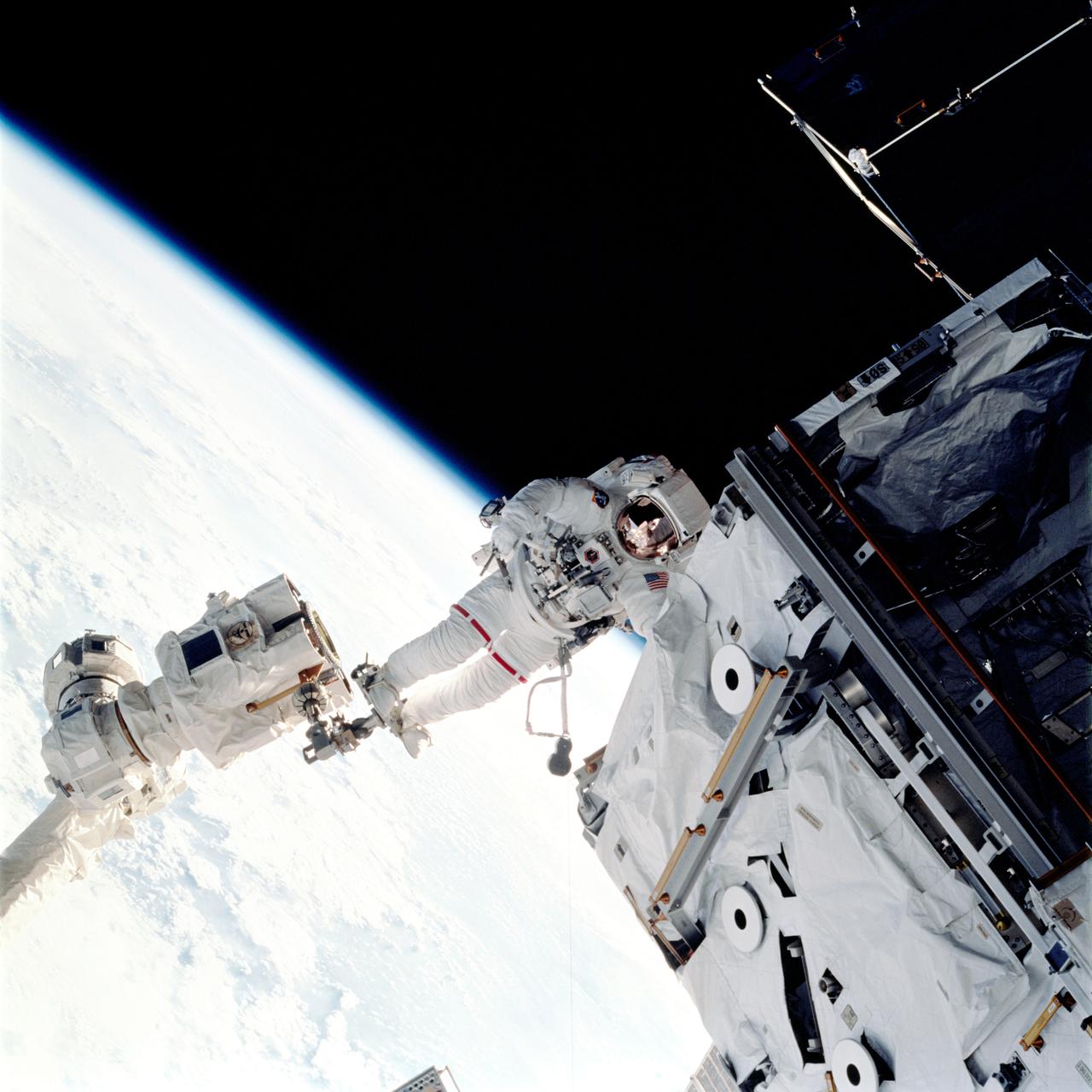
Launched aboard the Space Shuttle Orbiter Atlantis on April 8, 2002, the STS-110 mission prepared the International Space Station (ISS) for future space walks by installing and outfitting the 43-foot-long Starboard side S0 (S-zero) truss and preparing the first railroad in space, the Mobile Transporter. The 27,000 pound S0 truss was the first of 9 segments that will make up the Station's external framework that will eventually stretch 356 feet (109 meters), or approximately the length of a football field. This central truss segment also includes a flatcar called the Mobile Transporter and rails that will become the first "space railroad," which will allow the Station's robotic arm to travel up and down the finished truss for future assembly and maintenance. The completed truss structure will hold solar arrays and radiators to provide power and cooling for additional international research laboratories from Japan and Europe that will be attached to the Station. STS-110 Extravehicular Activity (EVA) marked the first use of the Station's robotic arm to maneuver space walkers around the Station and was the first time all of a shuttle crew's space walks were based out of the Station's Quest Airlock. In this photograph, Astronaut Jerry L. Ross, mission specialist, anchored on the end of the Canadarm2, moves near the newly installed S0 truss. Astronaut Lee M. E. Morin, mission specialist, (out of frame), worked in tandem with Ross during this fourth and final scheduled session of EVA for the STS-110 mission. The final major task of the space walk was the installation of a beam, the Airlock Spur, between the Quest Airlock and the S0. The spur will be used by space walkers in the future as a path from the airlock to the truss.
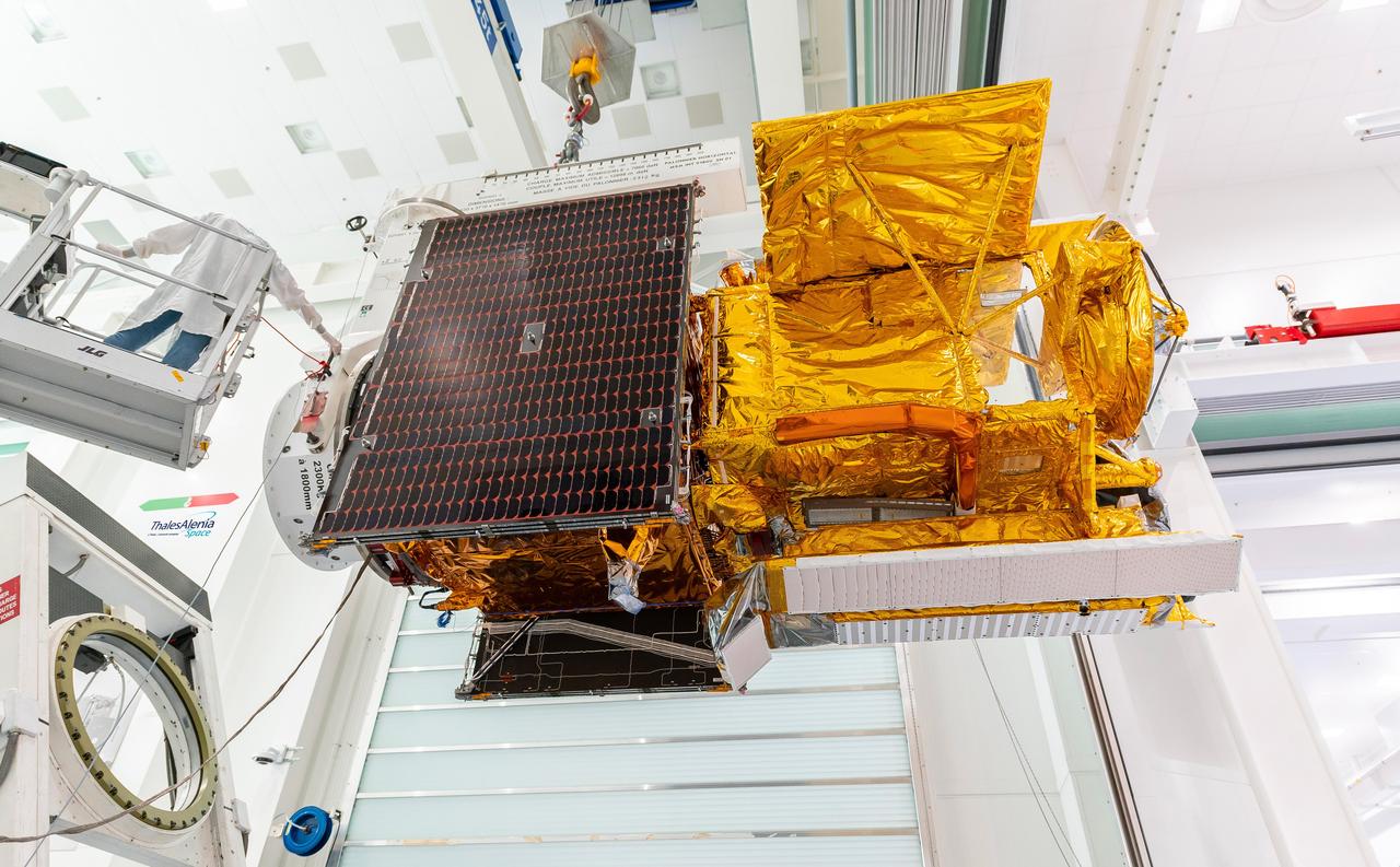
Workers in a clean room in Cannes, France, load the Surface Water and Ocean Topography (SWOT) satellite into a container in preparation for shipping the spacecraft to the U.S. SWOT is an international mission led by NASA and the French space agency Centre National d'Études Spatiales (CNES) that will survey water on more than 90% of Earth's surface. The spacecraft will view water in Earth's lakes, rivers, reservoirs, and the ocean in higher definition than ever before. The information that SWOT gathers will help inform water management decisions and prepare communities for rising seas and changing coastlines. It will also help researchers better understand the exchange of heat and carbon between the ocean and atmosphere, an important component of the role that Earth's ocean plays in the planet's climate. SWOT will launch out of the Vandenberg Space Force Base in central California no earlier than Dec. 5, 2022. SWOT is being jointly developed by NASA and CNES, with contributions from the Canadian Space Agency and the United Kingdom Space Agency. JPL, which is managed for NASA by Caltech in Pasadena, California, leads the U.S. component of the project. For the flight system payload, NASA is providing the KaRIn instrument, a GPS science receiver, a laser retroreflector, a two-beam microwave radiometer, and NASA instrument operations. CNES is providing the Doppler Orbitography and Radioposition Integrated by Satellite (DORIS) system, the dual frequency Poseidon altimeter (developed by Thales Alenia Space), the KaRIn radio-frequency subsystem (together with Thales Alenia Space and with support from the UK Space Agency), the platform, and ground control segment. CSA is providing the KaRIn high-power transmitter assembly. NASA is providing the launch vehicle and associated launch services. https://photojournal.jpl.nasa.gov/catalog/PIA24910
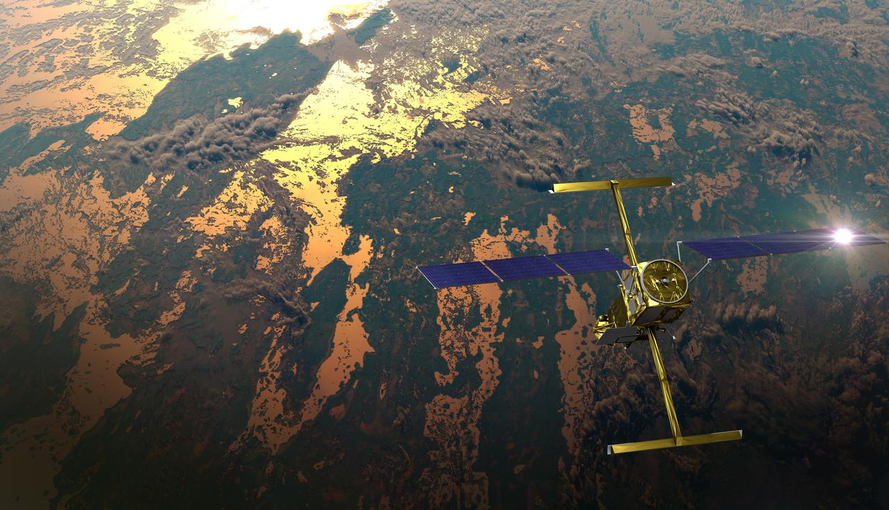
The international Surface Water and Ocean Topography (SWOT) satellite is shown in orbit over Earth in this illustration, with sunlight glinting off one of its solar arrays and both antennas of its Ka-band Radar Interferometer (KaRIn) instrument extended. The mission is a collaborative effort between NASA and the French space agency Centre National d'Études Spatiales (CNES) – with contributions from the Canadian Space Agency (CSA) and the UK Space Agency. KaRIn is the scientific heart of the SWOT satellite, which will survey the water on more than 90% of Earth's surface, measuring the height of water in lakes, rivers, reservoirs, and the ocean. To do that, KaRIn will transmit radar pulses to Earth's surface and use its two antennas to triangulate the return signals that bounce back. Mounted at the ends of a boom 33 feet (10 meters) long, the antennas will collect data along a swath 30 miles (50 kilometers) wide on either side of the satellite. KaRIn will operate in two modes: A lower-resolution mode over the ocean will involve significant onboard processing of the data to reduce the volume of information sent during downlinks to Earth; a higher-resolution mode will be used mainly over land. Scheduled to launch from Vandenberg Space Force Base in Central California on Dec. 15, 2022, SWOT is being jointly developed by NASA and CNES, with contributions from the CSA and the UK Space Agency. NASA's Jet Propulsion Laboratory, which is managed for the agency by Caltech in Pasadena, California, leads the U.S. component of the project. For the flight system payload, NASA is providing the Ka-band Radar Interferometer (KaRIn) instrument, a GPS science receiver, a laser retroreflector, a two-beam microwave radiometer, and NASA instrument operations. CNES is providing the Doppler Orbitography and Radioposition Integrated by Satellite (DORIS) system, the dual frequency Poseidon altimeter (developed by Thales Alenia Space), the KaRIn radio-frequency subsystem (together with Thales Alenia Space and with support from the UK Space Agency), the satellite platform, and ground control segment. CSA is providing the KaRIn high-power transmitter assembly. NASA is providing the launch vehicle and associated launch services. https://photojournal.jpl.nasa.gov/catalog/PIA25595
This infrared photograph shows the uplink laser beacon for NASA's Deep Space Optical Communications (DSOC) experiment beaming into the night sky from the Optical Communications Telescope Laboratory (OCTL) at NASA Jet Propulsion Laboratory's Table Mountain Facility near Wrightwood, California. Attached to the agency's Psyche spacecraft, the DSOC flight laser transceiver can receive and send data from Earth in encoded photons. As the experiment's ground laser transmitter, OCTL transmits at an infrared wavelength of 1,064 nanometers from its 3.3-foot-aperture (1-meter) telescope. The telescope can also receive faint infrared photons (at a wavelength of 1,550 nanometers) from the 4-watt flight laser transceiver on Psyche. Neither infrared wavelength is easily absorbed or scattered by Earth's atmosphere, making both ideal for deep space optical communications. To receive the most distant signals from Psyche, the project enlisted the powerful 200-inch-aperture (5-meter) Hale Telescope at Caltech's Palomar Observatory in San Diego County, California, as its primary downlink station, which provided adequate light-collecting area to capture the faintest photons. Those photons were then directed to a cryogenically cooled superconducting high-efficiency detector array at the observatory where the information encoded in the photons could be processed. Managed by JPL, DSOC was designed to demonstrate that data encoded in laser photons could be reliably transmitted, received, and then decoded after traveling millions of miles from Earth out to Mars distances. Nearly two years after launching aboard the agency's Psyche mission in 2023, the demonstration completed its 65th and final "pass" on Sept. 2, 2025, sending a laser signal to Psyche and receiving the return signal from 218 million miles (350 million kilometers) away. https://photojournal.jpl.nasa.gov/catalog/PIA26662
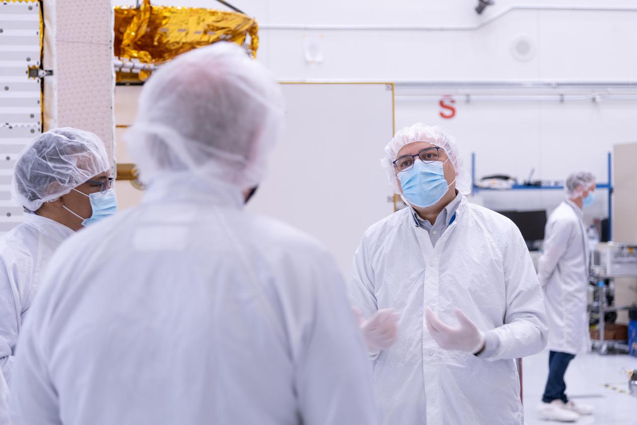
The new international satellite mission called Surface Water and Ocean Topography (SWOT) — slated for launch in late 2022 — will measure the height of Earth's surface water. The data the spacecraft will collect will help researchers understand and track the volume and location of water around the world. The satellite will assist with monitoring changes in floodplains and wetlands, measuring how much fresh water flows into and out of lakes and rivers and back to the ocean, and tracking regional shifts in sea level at scales never seen before. The satellite will also provide information on small-scale ocean currents that will support real-time marine operations affected by tides, currents, storm surge, sediment transport, and water quality issues. The payload is taking shape in a clean room at NASA's Jet Propulsion Laboratory in Southern California before being shipped to France. There, technicians and engineers from the French space agency Centre National d'Etudes Spatial (CNES), their prime contractor Thales Alenia Space, and JPL will complete the build and prepare the satellite for shipment to its California launch site at Vandenberg Air Force Base. JPL project manager Parag Vaze (pronounced vah-zay) is central to ensuring the handoff to his CNES counterpart Thierry Lafon goes smoothly. SWOT is being jointly developed by NASA and CNES, with contributions from the Canadian Space Agency (CSA) and United Kingdom Space Agency (UKSA). JPL, which is managed for NASA by Caltech in Pasadena, California, leads the U.S. component of the project. For the flight system, NASA is providing the Ka-band Radar Interferometer (KaRIn) instrument, a GPS science receiver, a laser retroreflector, and a two-beam microwave radiometer. CNES is providing the Doppler Orbitography and Radioposition Integrated by Satellite (DORIS) system, nadir altimeter, and the KaRIn RF subsystem (with support from the UKSA). CSA is providing the KaRIn high-power transmitter assembly. NASA is providing associated launch services. https://photojournal.jpl.nasa.gov/catalog/PIA24531
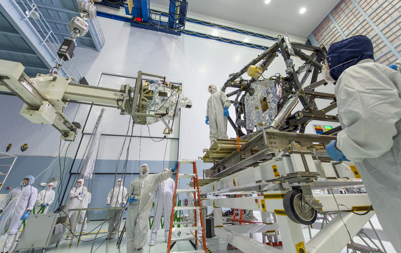
The MIRI itself weighs 181 pounds (82 kg) and is being held by a special balance beam (on the left of the photo), which is being maneuvered using a precision overhead crane by the engineer at the base of the ladder. Photo Credit: NASA/Chris Gunn; Text Credit: NASA/Laura Betz ---- Engineers worked meticulously to implant the James Webb Space Telescope's Mid-Infrared Instrument into the ISIM, or Integrated Science Instrument Module, in the cleanroom at NASA's Goddard Space Flight Center in Greenbelt, Md. As the successor to NASA's Hubble Space Telescope, the Webb telescope will be the most powerful space telescope ever built. It will observe the most distant objects in the universe, provide images of the first galaxies formed and see unexplored planets around distant stars. For more information, visit: <a href="http://www.jwst.nasa.gov" rel="nofollow">www.jwst.nasa.gov</a> <b><a href="http://www.nasa.gov/audience/formedia/features/MP_Photo_Guidelines.html" rel="nofollow">NASA image use policy.</a></b> <b><a href="http://www.nasa.gov/centers/goddard/home/index.html" rel="nofollow">NASA Goddard Space Flight Center</a></b> enables NASA’s mission through four scientific endeavors: Earth Science, Heliophysics, Solar System Exploration, and Astrophysics. Goddard plays a leading role in NASA’s accomplishments by contributing compelling scientific knowledge to advance the Agency’s mission. <b>Follow us on <a href="http://twitter.com/NASA_GoddardPix" rel="nofollow">Twitter</a></b> <b>Like us on <a href="http://www.facebook.com/pages/Greenbelt-MD/NASA-Goddard/395013845897?ref=tsd" rel="nofollow">Facebook</a></b> <b>Find us on <a href="http://instagram.com/nasagoddard?vm=grid" rel="nofollow">Instagram</a></b>
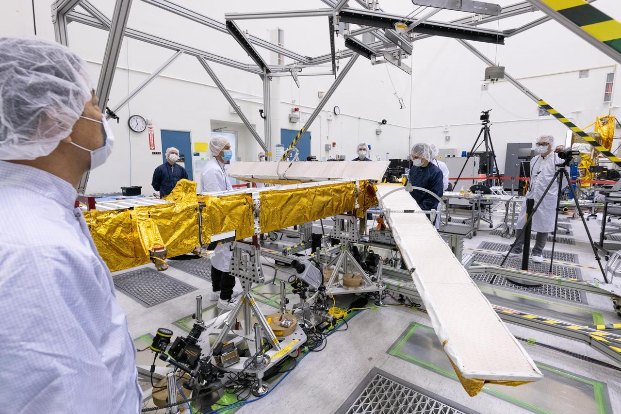
Members of the international Surface Water and Ocean Topography (SWOT) mission test one of the antennas for the Ka-band Radar Interferometer (KaRIn) instrument in a clean room at NASA's Jet Propulsion Laboratory in Southern California. The mission is a collaborative effort between NASA and the French space agency Centre National d'Études Spatiales (CNES) – with contributions from the Canadian Space Agency (CSA) and the UK Space Agency. KaRIn is the scientific heart of the SWOT satellite, which will survey the water on more than 90% of Earth's surface, measuring the height of water in lakes, rivers, reservoirs, and the ocean. To do that, KaRIn will transmit radar pulses to Earth's surface and use its two antennas to triangulate the return signals that bounce back. Mounted at the ends of a boom 33 feet (10 meters) long, the antennas will collect data along a swath 30 miles (50 kilometers) wide on either side of the satellite. KaRIn will operate in two modes: A lower-resolution mode over the ocean will involve significant onboard processing of the data to reduce the volume of information sent during downlinks to Earth; a higher-resolution mode will be used mainly over land. Scheduled to launch from Vandenberg Space Force Base in Central California on Dec. 15, 2022, SWOT is being jointly developed by NASA and CNES, with contributions from the CSA and the UK Space Agency. NASA's Jet Propulsion Laboratory, which is managed for the agency by Caltech in Pasadena, California, leads the U.S. component of the project. For the flight system payload, NASA is providing the Ka-band Radar Interferometer (KaRIn) instrument, a GPS science receiver, a laser retroreflector, a two-beam microwave radiometer, and NASA instrument operations. CNES is providing the Doppler Orbitography and Radioposition Integrated by Satellite (DORIS) system, the dual frequency Poseidon altimeter (developed by Thales Alenia Space), the KaRIn radio-frequency subsystem (together with Thales Alenia Space and with support from the UK Space Agency), the satellite platform, and ground control segment. CSA is providing the KaRIn high-power transmitter assembly. NASA is providing the launch vehicle and associated launch services. https://photojournal.jpl.nasa.gov/catalog/PIA25594

NASA image release April 27, 2012 The NASA/ESA Hubble Space Telescope has been at the cutting edge of research into what happens to stars like our sun at the ends of their lives. One stage that stars pass through as they run out of nuclear fuel is called the preplanetary or protoplanetary nebula stage. This Hubble image of the Egg Nebula shows one of the best views to date of this brief but dramatic phase in a star’s life. The preplanetary nebula phase is a short period in the cycle of stellar evolution, and has nothing to do with planets. Over a few thousand years, the hot remains of the aging star in the center of the nebula heat it up, excite the gas, and make it glow as a subsequent planetary nebula. The short lifespan of preplanetary nebulae means there are relatively few of them in existence at any one time. Moreover, they are very dim, requiring powerful telescopes to be seen. This combination of rarity and faintness means they were only discovered comparatively recently. The Egg Nebula, the first to be discovered, was first spotted less than 40 years ago, and many aspects of this class of object remain shrouded in mystery. At the center of this image, and hidden in a thick cloud of dust, is the nebula’s central star. While we can’t see the star directly, four searchlight beams of light coming from it shine out through the nebula. It is thought that ring-shaped holes in the thick cocoon of dust, carved by jets coming from the star, let the beams of light emerge through the otherwise opaque cloud. The precise mechanism by which stellar jets produce these holes is not known for certain, but one possible explanation is that a binary star system, rather than a single star, exists at the center of the nebula. The onion-like layered structure of the more diffuse cloud surrounding the central cocoon is caused by periodic bursts of material being ejected from the dying star. The bursts typically occur every few hundred years. The distance to the Egg Nebula is only known very approximately, the best guess placing it at around 3,000 light-years from Earth. This in turn means that astronomers do not have any accurate figures for the size of the nebula (it may be larger and further away, or smaller but nearer). This image is produced from exposures in visible and infrared light from Hubble’s Wide Field Camera 3. Credit: ESA/Hubble, NASA <b><a href="http://www.nasa.gov/audience/formedia/features/MP_Photo_Guidelines.html" rel="nofollow">NASA image use policy.</a></b> <b><a href="http://www.nasa.gov/centers/goddard/home/index.html" rel="nofollow">NASA Goddard Space Flight Center</a></b> enables NASA’s mission through four scientific endeavors: Earth Science, Heliophysics, Solar System Exploration, and Astrophysics. Goddard plays a leading role in NASA’s accomplishments by contributing compelling scientific knowledge to advance the Agency’s mission. <b>Follow us on <a href="http://twitter.com/NASAGoddardPix" rel="nofollow">Twitter</a></b> <b>Like us on <a href="http://www.facebook.com/pages/Greenbelt-MD/NASA-Goddard/395013845897?ref=tsd" rel="nofollow">Facebook</a></b> <b>Find us on <a href="http://instagrid.me/nasagoddard/?vm=grid" rel="nofollow">Instagram</a></b>
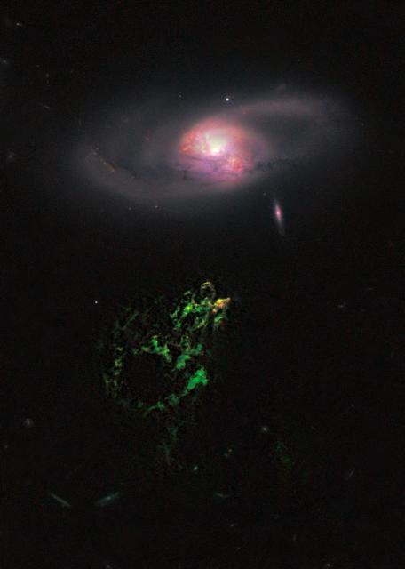
NASA image release January 10, 2011 In this image by NASA's Hubble Space Telescope, an unusual, ghostly green blob of gas appears to float near a normal-looking spiral galaxy. The bizarre object, dubbed Hanny's Voorwerp (Hanny's Object in Dutch), is the only visible part of a 300,000-light-year-long streamer of gas stretching around the galaxy, called IC 2497. The greenish Voorwerp is visible because a searchlight beam of light from the galaxy's core illuminated it. This beam came from a quasar, a bright, energetic object that is powered by a black hole. The quasar may have turned off about 200,000 years ago. This Hubble view uncovers a pocket of star clusters, the yellowish-orange area at the tip of Hanny's Voorwerp. The star clusters are confined to an area that is a few thousand light-years wide. The youngest stars are a couple of million years old. The Voorwerp is the size of our Milky Way galaxy, and its bright green color is from glowing oxygen. Hubble also shows that gas flowing from IC 2497 may have instigated the star birth by compressing the gas in Hanny's Voorwerp. The galaxy is located about 650 million light-years from Earth. What appears to be a gaping hole in Hanny's Voorwerp actually may be a shadow cast by an object in the quasar's light path. The feature gives the illusion of a hole about 20,000 light-years wide. Hubble reveals sharp edges but no other changes in the gas around the apparent opening, suggesting that an object close to the quasar may have blocked some of the light and projected a shadow on the Voorwerp. This phenomenon is similar to a fly on a movie projector lens casting a shadow on a movie screen. An interaction between IC 2497 and another galaxy about a billion years ago may have created Hanny's Voorwerp and fueled the quasar. The Hubble image shows that IC 2497 has been disturbed, with complex dust patches, warped spiral arms, and regions of star formation around its core. These features suggest the aftermath of a galaxy merger. The bright spots in the central part of the galaxy are star-forming regions. The small, pinkish object to the lower right of IC 2497 is an edge-on spiral galaxy in the background. The image was made by combining data from the Advanced Camera for Surveys (ACS) and the Wide Field Camera 3 (WFC3). The ACS exposures were taken April 12, 2010; the WFC3 data, April 4, 2010. Object Names: Hanny's Voorwerp, IC 2497 Image Type: Astronomical Credit: NASA, ESA, W. Keel (University of Alabama), and the Galaxy Zoo Team <b><a href="http://www.nasa.gov/centers/goddard/home/index.html" rel="nofollow">NASA Goddard Space Flight Center</a></b> enables NASA’s mission through four scientific endeavors: Earth Science, Heliophysics, Solar System Exploration, and Astrophysics. Goddard plays a leading role in NASA’s accomplishments by contributing compelling scientific knowledge to advance the Agency’s mission. <b>Follow us on <a href="http://twitter.com/NASA_GoddardPix" rel="nofollow">Twitter</a></b> <b>Join us on <a href="http://www.facebook.com/pages/Greenbelt-MD/NASA-Goddard/395013845897?ref=tsd" rel="nofollow">Facebook</a></b>
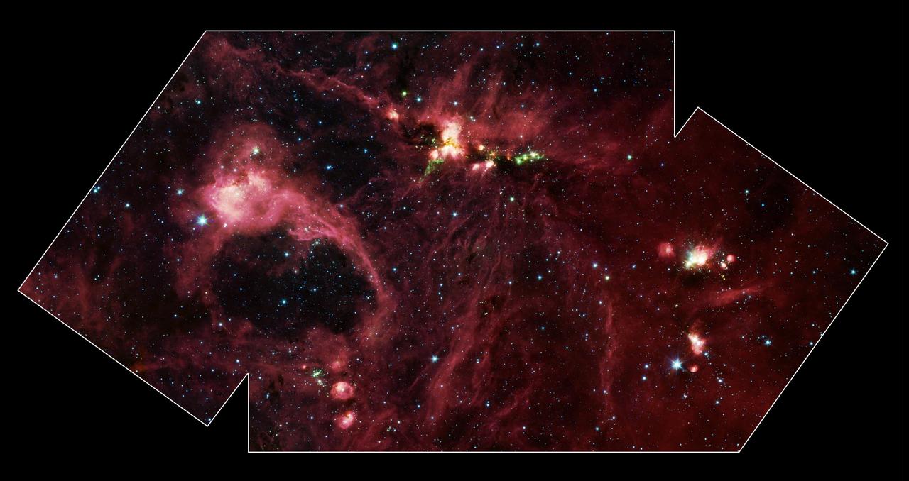
Hidden behind a shroud of dust in the constellation Cygnus is a stellar nursery called DR21, which is giving birth to some of the most massive stars in our galaxy. Visible light images reveal no trace of this interstellar cauldron because of heavy dust obscuration. In fact, visible light is attenuated in DR21 by a factor of more than 10,000,000,000,000,000,000,000,000,000,000,000,000,000 (ten thousand trillion heptillion). New images from NASA's Spitzer Space Telescope allow us to peek behind the cosmic veil and pinpoint one of the most massive natal stars yet seen in our Milky Way galaxy. The never-before-seen star is 100,000 times as bright as the Sun. Also revealed for the first time is a powerful outflow of hot gas emanating from this star and bursting through a giant molecular cloud. This image is a large-scale mosaic assembled from individual photographs obtained with the InfraRed Array Camera (IRAC) aboard Spitzer. The image covers an area about two times that of a full moon. The mosaic is a composite of images obtained at mid-infrared wavelengths of 3.6 microns (blue), 4.5 microns (green), 5.8 microns (orange) and 8 microns (red). The brightest infrared cloud near the top center corresponds to DR21, which presumably contains a cluster of newly forming stars at a distance of 10,000 light-years. Protruding out from DR21 toward the bottom left of the image is a gaseous outflow (green), containing both carbon monoxide and molecular hydrogen. Data from the Spitzer spectrograph, which breaks light into its constituent individual wavelengths, indicate the presence of hot steam formed as the outflow heats the surrounding molecular gas. Outflows are physical signatures of processes that create supersonic beams, or jets, of gas. They are usually accompanied by discs of material around the new star, which likely contain the materials from which future planetary systems are formed. Additional newborn stars, depicted in green, can be seen surrounding the DR21 region. The red filaments stretching across this image denote the presence of polycyclic aromatic hydrocarbons. These organic molecules, comprised of carbon and hydrogen, are excited by surrounding interstellar radiation and become luminescent at wavelengths near 8.0 microns. The complex pattern of filaments is caused by an intricate combination of radiation pressure, gravity and magnetic fields. The result is a tapestry in which winds, outflows and turbulence move and shape the interstellar medium. To the lower left of the mosaic is a large bubble of gas and dust, which may represent the remnants of a past generation of stars. http://photojournal.jpl.nasa.gov/catalog/PIA05732
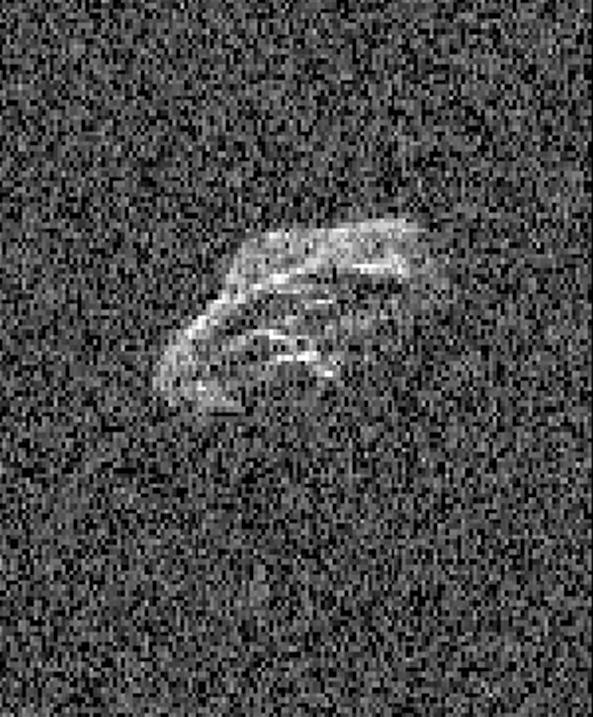
Scientists using two giant, Earth-based radio telescopes bounced radar signals off passing asteroid 2011 UW158 to create images for this animation showing the rocky body's fast rotation. The passing asteroid made its closest approach to Earth on July 19, 2015 at 7:37 a.m. PST (4:37 a.m. EST) at a distance of about 1.5 million miles (2.4 million kilometers, or 6 times the distance from Earth to the moon). The close proximity during the pass made 2011 UW158 one of the best asteroid flybys of 2015 for imaging from Earth using radar. The radar images reveal that the shape of the asteroid is extremely irregular and quite elongated. Prominent parallel, linear features run along the length of the object that cause a large increase in brightness of the radar images as they rotate into view. Scientists note that the asteroid appears to be fairly unusual. Its fast rotation suggests the object has greater mechanical strength than other asteroids its size. A fast-rotating asteroid with lower mechanical strength would tend to split apart. To obtain the views, researchers paired the 230-foot- (70-meter-) wide Deep Space Network antenna at Goldstone, California, in concert with the National Radio Astronomy Observatory's 330-foot (100-meter) Green Bank Telescope. Using this technique, the Goldstone antenna beams a radar signal at an asteroid and Green Bank receives the reflections. The technique, referred to as a bi-static observation, dramatically improves the amount of detail that can be seen in radar images. The new views obtained with the technique show features as small as about 24 feet (7.5 meters) wide. The 171 individual images used in the movie were generated from data collected on July 18. They show the asteroid is approximately 2000 by 1000 feet (600 by 300 meters) across. The observations also confirm earlier estimates by astronomers that the asteroid rotates quickly, completing one spin in just over half an hour. The movie spans a period of about an hour and 45 minutes. The trajectory of asteroid 2011 UW158 is well understood. This flyby was the closest approach the asteroid will make to Earth for at least the next 93 years. Asteroid 2011 UW158 was discovered on October 25, 2011, by the PanSTARRS 1 telescope, located on the summit of Haleakala on Maui, Hawaii. Managed by the University of Hawaii, the PanSTARRS survey receives NASA funding. Radar is a powerful technique for studying an asteroid's size, shape, rotation state, surface features and surface roughness, and for improving the calculation of asteroid orbits. Radar measurements of asteroid distances and velocities often enable computation of asteroid orbits much further into the future than if radar observations weren't available. http://photojournal.jpl.nasa.gov/catalog/PIA19644
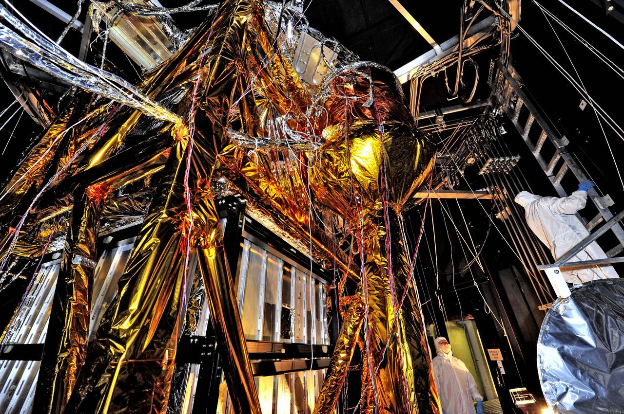
NASA image release August 23, 2012 What looks like a giant golden spider weaving a web of cables and cords, is actually ground support equipment, including the Optical Telescope Simulator (OSIM), for the James Webb Space Telescope. OSIM's job is to generate a beam of light just like the one that the real telescope optics will feed into the actual flight instruments. Because the real flight instruments will be used to test the real flight telescope, their alignment and performance first have to be verified by using the OSIM. Engineers are thoroughly checking out OSIM now in preparation for using it to test the flight science instruments later. This photo was taken from inside a large thermal-vacuum chamber called the Space Environment Simulator (SES), at NASA's Goddard Space Flight Center in Greenbelt, Md. Engineers have blanketed the structure of the OSIM with special insulating material to help control its temperature while it goes into the deep freeze testing that mimics the chill of space that Webb will ultimately experience in its operational orbit over 1 million miles from Earth. The golden-colored thermal blankets are made of aluminized kapton, a polymer film that remains stable over a wide range of temperatures. The structure that looks like a silver and black cube underneath the "spider" is a set of cold panels that surround OSIM's optics. During testing, OSIM's temperature will drop to 100 Kelvin (-280 F or -173 C) as liquid nitrogen flows through tubes welded to the chamber walls and through tubes along the silver panels surrounding OSIM's optics. These cold panels will keep the OSIM optics very cold, but the parts covered by the aluminized kapton blankets will stay warm. "Some blankets have silver facing out and gold facing in, or inverted, or silver on both sides, etc.," says Erin Wilson, a Goddard engineer. "Depending on which side of the blanket your hardware is looking at, the blankets can help it get colder or stay warmer, in an environmental test." Another reason for thermal blankets is to shield the cold OSIM optics from unwanted stray infrared light. When the OSIM is pointing its calibrated light beam at Webb's science instruments, engineers don't want any stray infrared light, such as "warm photons" from warm structures, leaking into the instruments' field of view. Too much of this stray light would raise the background too much for the instruments to "see" light from the OSIM—it would be like trying to photograph a lightning bug flying in front of car headlights. To get OSIM's optics cold, the inside of the chamber has to get cold, and to do that, all the air has to be pumped out to create a vacuum. Then liquid nitrogen has to be run though the plumbing along the inner walls of the chamber. Wilson notes that's why the blankets have to have vents in them: "That way, the air between all the layers can be evacuated as the chamber pressure drops, otherwise the blankets could pop," says Wilson. The most powerful space telescope ever built, Webb is the successor to NASA's Hubble Space Telescope. Webb's four instruments will reveal how the universe evolved from the Big Bang to the formation of our solar system. Webb is a joint project of NASA, the European Space Agency and the Canadian Space Agency. Credit: NASA/GSFC/Chris Gunn <b><a href="http://www.nasa.gov/audience/formedia/features/MP_Photo_Guidelines.html" rel="nofollow">NASA image use policy.</a></b> <b><a href="http://www.nasa.gov/centers/goddard/home/index.html" rel="nofollow">NASA Goddard Space Flight Center</a></b> enables NASA’s mission through four scientific endeavors: Earth Science, Heliophysics, Solar System Exploration, and Astrophysics. Goddard plays a leading role in NASA’s accomplishments by contributing compelling scientific knowledge to advance the Agency’s mission. <b>Follow us on <a href="http://twitter.com/NASA_GoddardPix" rel="nofollow">Twitter</a></b> <b>Like us on <a href="http://www.facebook.com/pages/Greenbelt-MD/NASA-Goddard/395013845897?ref=tsd" rel="nofollow">Facebook</a></b> <b>Find us on <a href="http://instagrid.me/nasagoddard/?vm=grid" rel="nofollow">Instagram</a></b>

Peering deep into the core of the Crab Nebula, this close-up image reveals the beating heart of one of the most historic and intensively studied remnants of a supernova, an exploding star. The inner region sends out clock-like pulses of radiation and tsunamis of charged particles embedded in magnetic fields. The neutron star at the very center of the Crab Nebula has about the same mass as the sun but compressed into an incredibly dense sphere that is only a few miles across. Spinning 30 times a second, the neutron star shoots out detectable beams of energy that make it look like it's pulsating. The NASA Hubble Space Telescope snapshot is centered on the region around the neutron star (the rightmost of the two bright stars near the center of this image) and the expanding, tattered, filamentary debris surrounding it. Hubble's sharp view captures the intricate details of glowing gas, shown in red, that forms a swirling medley of cavities and filaments. Inside this shell is a ghostly blue glow that is radiation given off by electrons spiraling at nearly the speed of light in the powerful magnetic field around the crushed stellar core. The neutron star is a showcase for extreme physical processes and unimaginable cosmic violence. Bright wisps are moving outward from the neutron star at half the speed of light to form an expanding ring. It is thought that these wisps originate from a shock wave that turns the high-speed wind from the neutron star into extremely energetic particles. When this "heartbeat" radiation signature was first discovered in 1968, astronomers realized they had discovered a new type of astronomical object. Now astronomers know it's the archetype of a class of supernova remnants called pulsars - or rapidly spinning neutron stars. These interstellar "lighthouse beacons" are invaluable for doing observational experiments on a variety of astronomical phenomena, including measuring gravity waves. Observations of the Crab supernova were recorded by Chinese astronomers in 1054 A.D. The nebula, bright enough to be visible in amateur telescopes, is located 6,500 light-years away in the constellation Taurus. Credits: NASA and ESA, Acknowledgment: J. Hester (ASU) and M. Weisskopf (NASA/MSFC) <b><a href="http://www.nasa.gov/audience/formedia/features/MP_Photo_Guidelines.html" rel="nofollow">NASA image use policy.</a></b> <b><a href="http://www.nasa.gov/centers/goddard/home/index.html" rel="nofollow">NASA Goddard Space Flight Center</a></b> enables NASA’s mission through four scientific endeavors: Earth Science, Heliophysics, Solar System Exploration, and Astrophysics. Goddard plays a leading role in NASA’s accomplishments by contributing compelling scientific knowledge to advance the Agency’s mission. <b>Follow us on <a href="http://twitter.com/NASAGoddardPix" rel="nofollow">Twitter</a></b> <b>Like us on <a href="http://www.facebook.com/pages/Greenbelt-MD/NASA-Goddard/395013845897?ref=tsd" rel="nofollow">Facebook</a></b> <b>Find us on <a href="http://instagrid.me/nasagoddard/?vm=grid" rel="nofollow">Instagram</a></b>