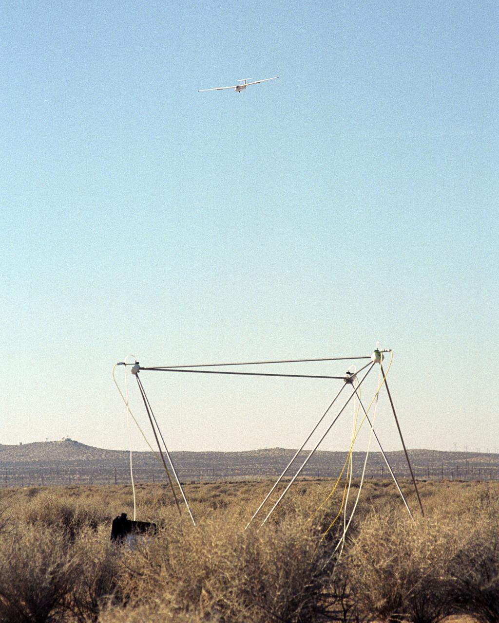
A United States Air Force Test Pilot School Blanik L-23 glider carrying a microphone and a pressure transducer flies near a BADS (Boom Amplitudes Direction System) sensor following flight at an altitude of 10 thousand feet under the path of the F-5E SSBE aircraft. The SSBE (Shaped Sonic Boom Experiment) was formerly known as the Shaped Sonic Boom Demonstration, or SSBD, and is part of DARPA's Quiet Supersonic Platform (QSP) program. On August 27, 2003, the F-5E SSBD aircraft demonstrated a method to reduce the intensity of sonic booms.
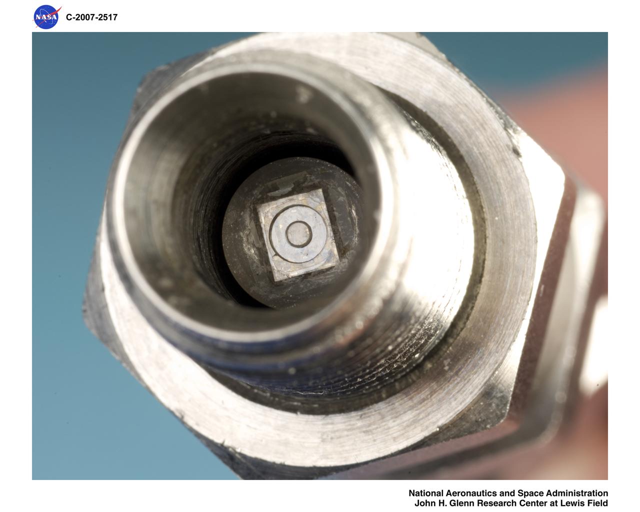
Fully Packaged Silicon Carbide Piezoresistive Pressure Transducer that measures pressures at temperature as high as 600 degrees Celsius
Fully Packaged Silicon Carbide Piezoresistive Pressure Transducer that measures pressures at temperature as high as 600 degrees Celsius

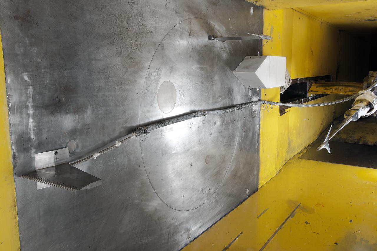
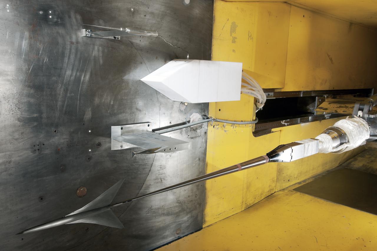
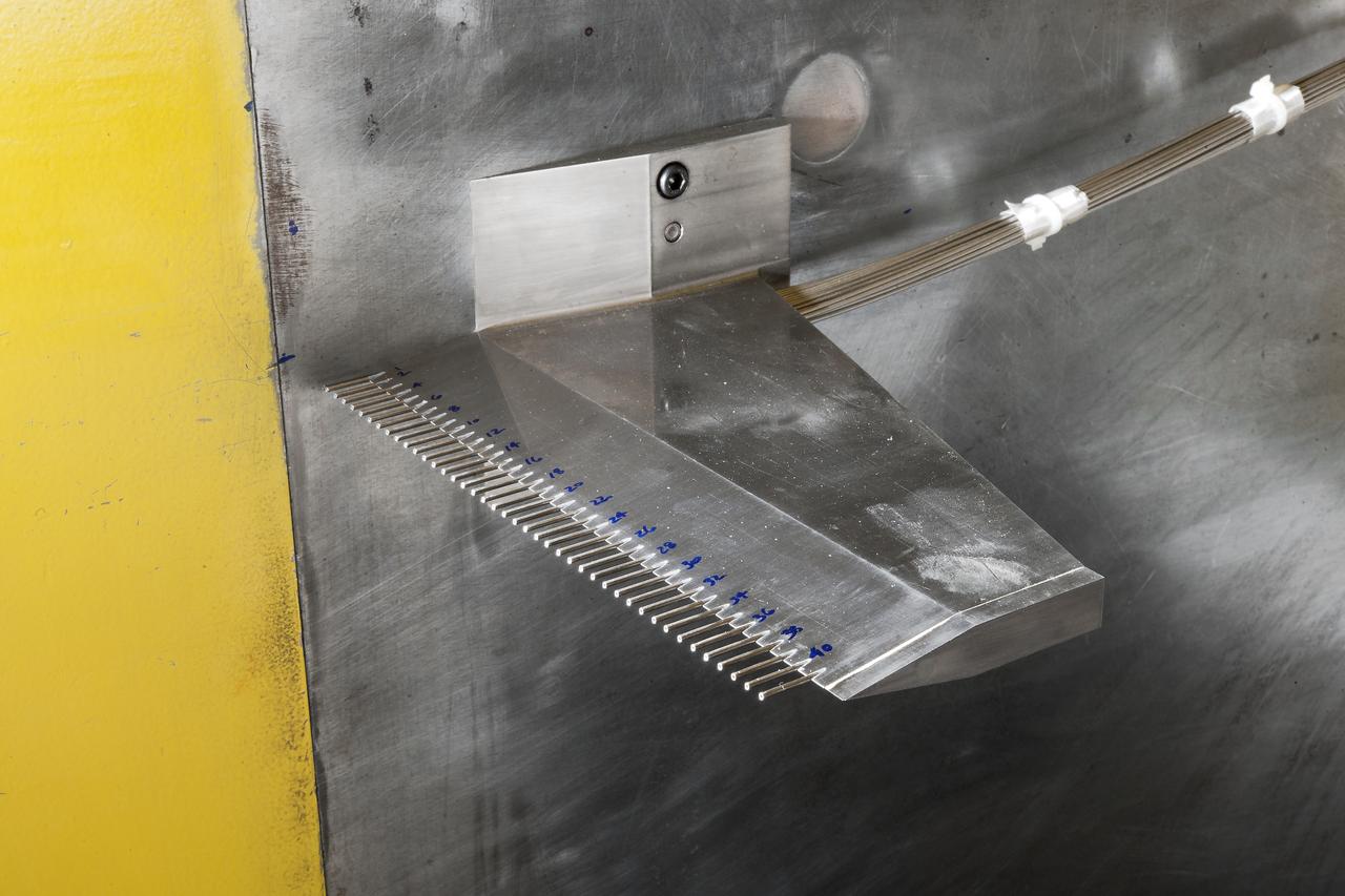
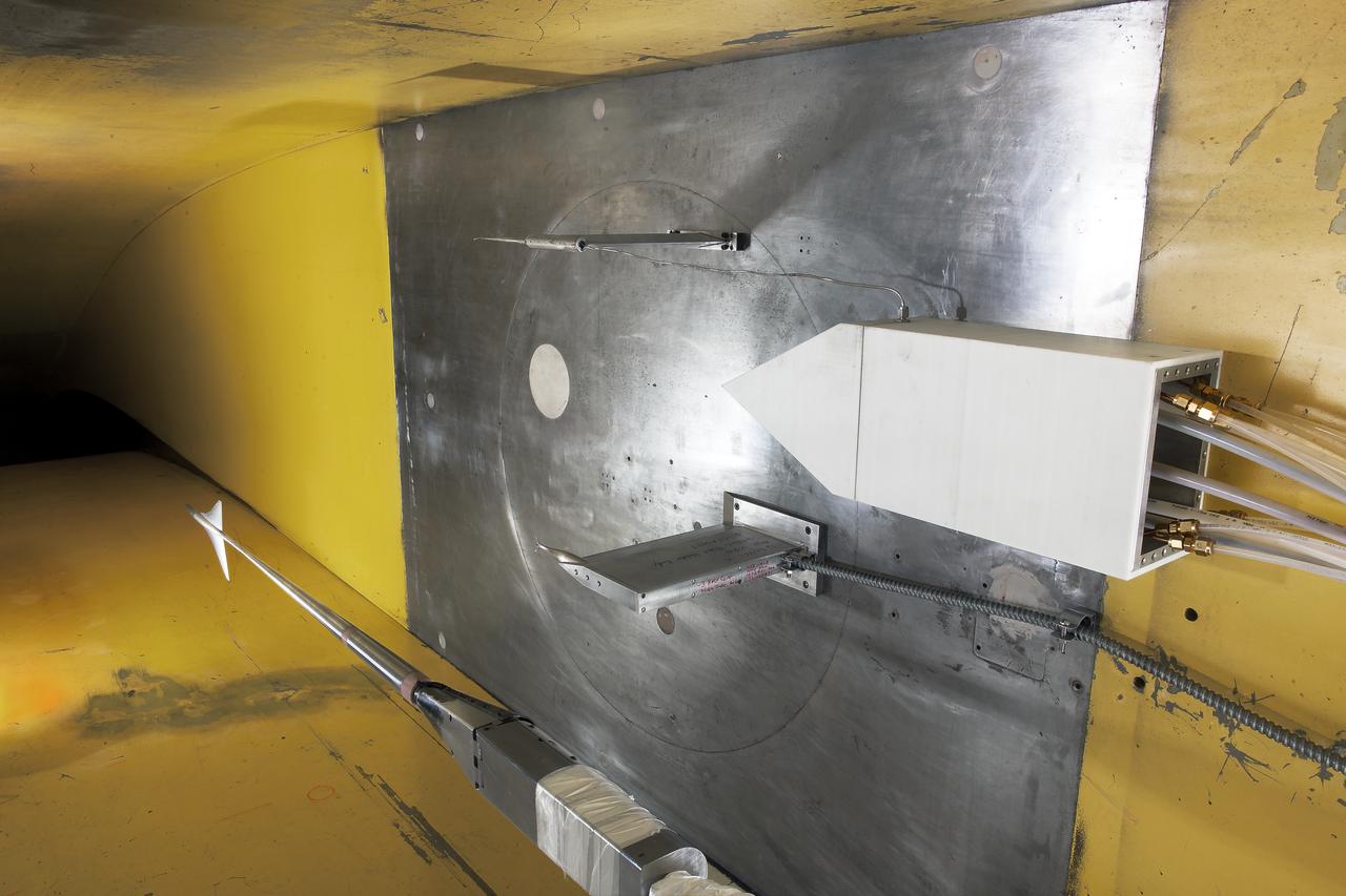
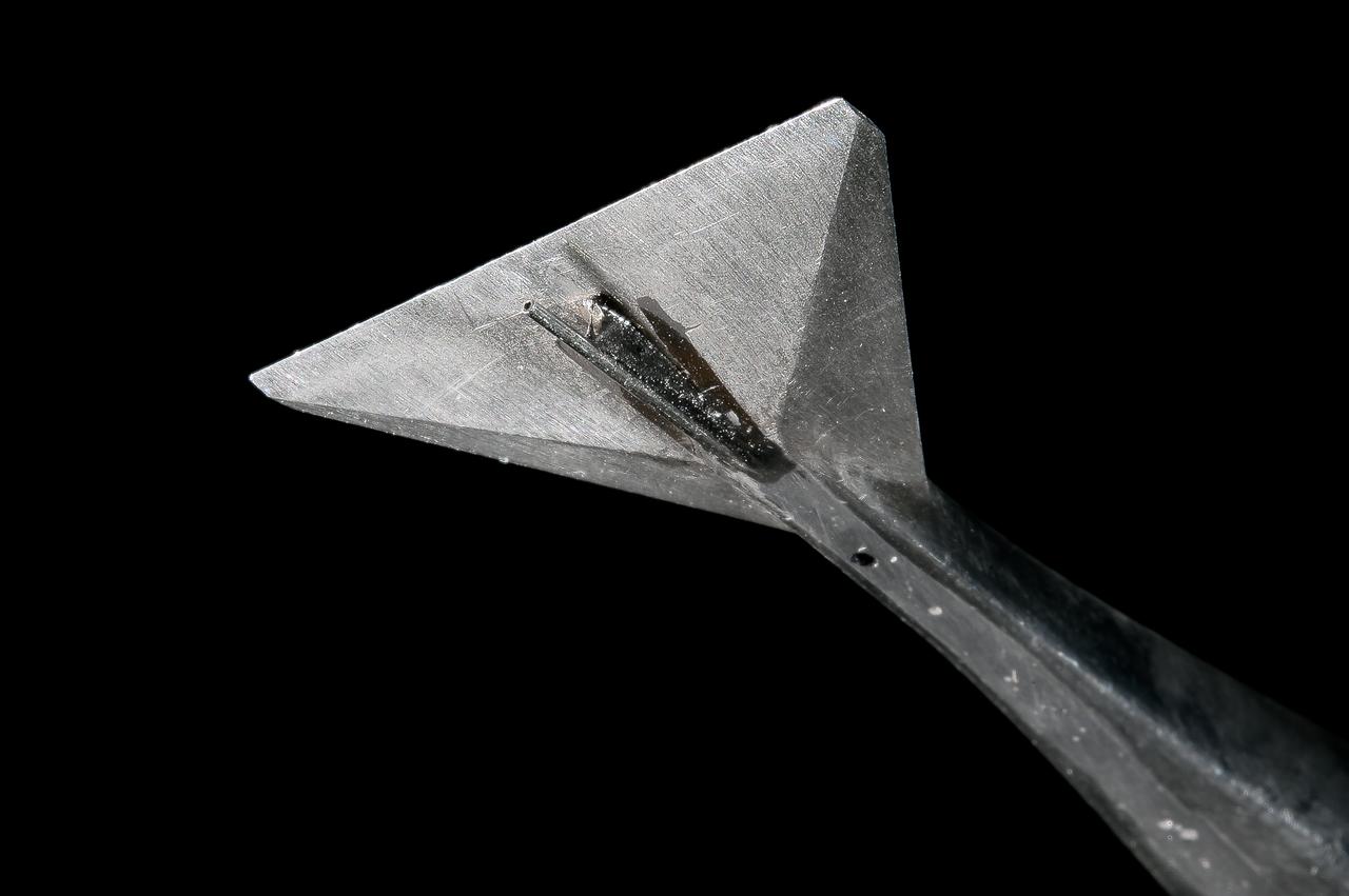
UPWT Test 1998 Continuous Data Sonic Boom Test. Sonic Boom Hardward Mounted in the Langley Unitary Plan wind Tunnel(UPWT). Conical survey probes, wedge probe, and wind tunnel wall boundary layer rake. Rectangular box with wedge front end is a transducer box to that held pressure transducer for the conical probes.
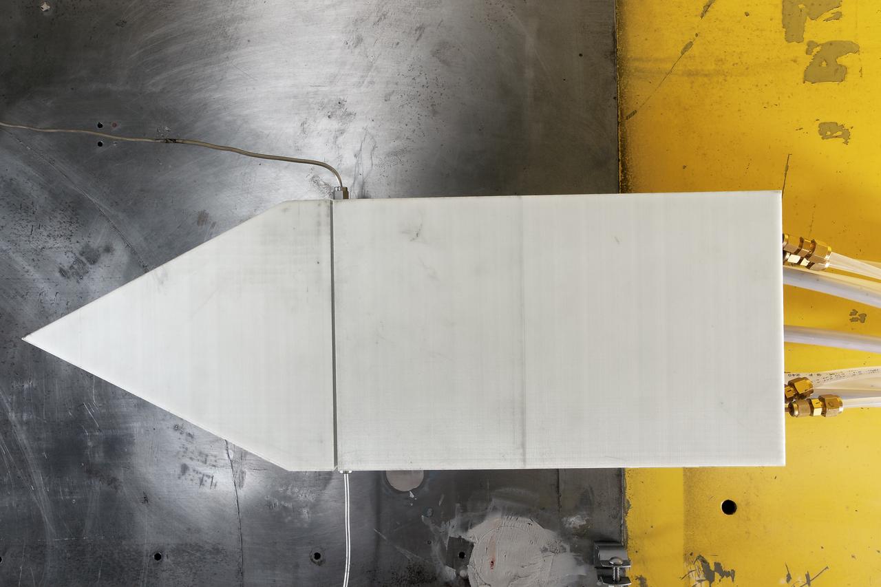
UPWT Test 1998 Continuous Data Sonic Boom Test. Sonic Boom Hardward Mounted in the Langley Unitary Plan wind Tunnel(UPWT). Conical survey probes, wedge probe, and wind tunnel wall boundary layer rake. Rectangular box with wedge front end is a transducer box to that held pressure transducer for the conical probes.
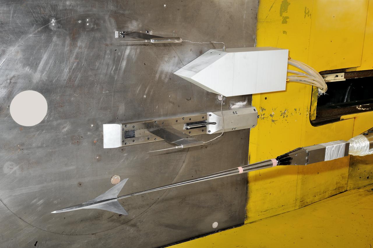
UPWT Test 1998 Continuous Data Sonic Boom Test. Sonic Boom Hardward Mounted in the Langley Unitary Plan wind Tunnel(UPWT). Conical survey probes, wedge probe, and wind tunnel wall boundary layer rake. Rectangular box with wedge front end is a transducer box to that held pressure transducer for the conical probes.
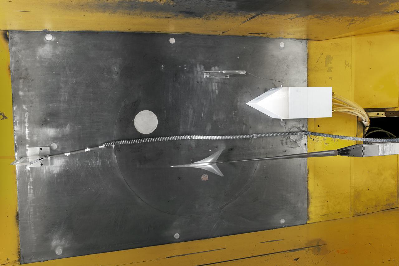
UPWT Test 1998 Continuous Data Sonic Boom Test. Sonic Boom Hardward Mounted in the Langley Unitary Plan wind Tunnel(UPWT). Conical survey probes, wedge probe, and wind tunnel wall boundary layer rake. Rectangular box with wedge front end is a transducer box to that held pressure transducer for the conical probes.
UPWT Test 1998 Continuous Data Sonic Boom Test. Sonic Boom Hardward Mounted in the Langley Unitary Plan wind Tunnel(UPWT). Conical survey probes, wedge probe, and wind tunnel wall boundary layer rake. Rectangular box with wedge front end is a transducer box to that held pressure transducer for the conical probes.
UPWT Test 1998 Continuous Data Sonic Boom Test. Sonic Boom Hardward Mounted in the Langley Unitary Plan wind Tunnel(UPWT). Conical survey probes, wedge probe, and wind tunnel wall boundary layer rake. Rectangular box with wedge front end is a transducer box to that held pressure transducer for the conical probes.
Two images left out of the original order in 2011 L numbers 3800-3810 2011. UPWT Test 1998 Continuous Data Sonic Boom Test. Sonic Boom Hardware Mounted in the Langley Unitary Plan wind Tunnel(UPWT). Conical survey probes, wedge probe, and wind tunnel wall boundary layer rake. Rectangular box with wedge front end is a transducer box to that held pressure transducer for the conical probes.
UPWT Test 1998 Continuous Data Sonic Boom Test. Sonic Boom Hardward Mounted in the Langley Unitary Plan wind Tunnel(UPWT). Conical survey probes, wedge probe, and wind tunnel wall boundary layer rake. Rectangular box with wedge front end is a transducer box to that held pressure transducer for the conical probes.
UPWT Test 1998 Continuous Data Sonic Boom Test. Sonic Boom Hardward Mounted in the Langley Unitary Plan wind Tunnel(UPWT). Conical survey probes, wedge probe, and wind tunnel wall boundary layer rake. Rectangular box with wedge front end is a transducer box to that held pressure transducer for the conical probes.
UPWT Test 1998 Continuous Data Sonic Boom Test. Sonic Boom Hardward Mounted in the Langley Unitary Plan wind Tunnel(UPWT). Conical survey probes, wedge probe, and wind tunnel wall boundary layer rake. Rectangular box with wedge front end is a transducer box to that held pressure transducer for the conical probes.
UPWT Test 1998 Continuous Data Sonic Boom Test. Sonic Boom Hardward Mounted in the Langley Unitary Plan wind Tunnel(UPWT). Conical survey probes, wedge probe, and wind tunnel wall boundary layer rake. Rectangular box with wedge front end is a transducer box to that held pressure transducer for the conical probes.
UPWT Test 1998 Continuous Data Sonic Boom Test. Sonic Boom Hardward Mounted in the Langley Unitary Plan wind Tunnel(UPWT). Conical survey probes, wedge probe, and wind tunnel wall boundary layer rake. Rectangular box with wedge front end is a transducer box to that held pressure transducer for the conical probes.
Two images left out of the original order in 2011 L numbers 3800-3810 2011. UPWT Test 1998 Continuous Data Sonic Boom Test. Sonic Boom Hardware Mounted in the Langley Unitary Plan wind Tunnel(UPWT). Conical survey probes, wedge probe, and wind tunnel wall boundary layer rake. Rectangular box with wedge front end is a transducer box to that held pressure transducer for the conical probes.
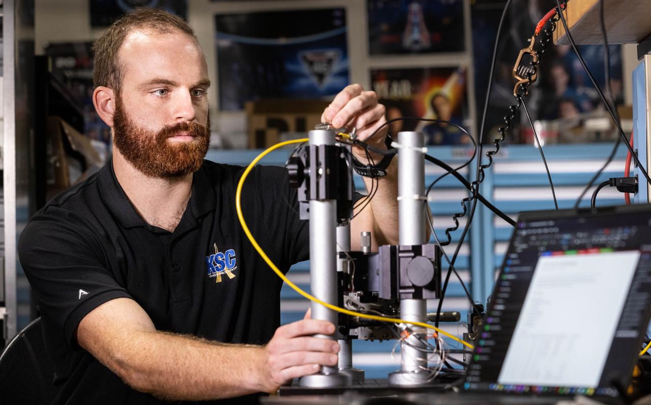
Stefan Tomovic from the Engineering Directorate at NASA’s Kennedy Space Center in Florida evaluates pressure transducers for NASA’s Engineering and Safety Center on Wednesday, Aug. 20, 2025. This probe is designed to improve the detection of thruster pressure sensor anomalies for the agency’s Commercial Crew Program.
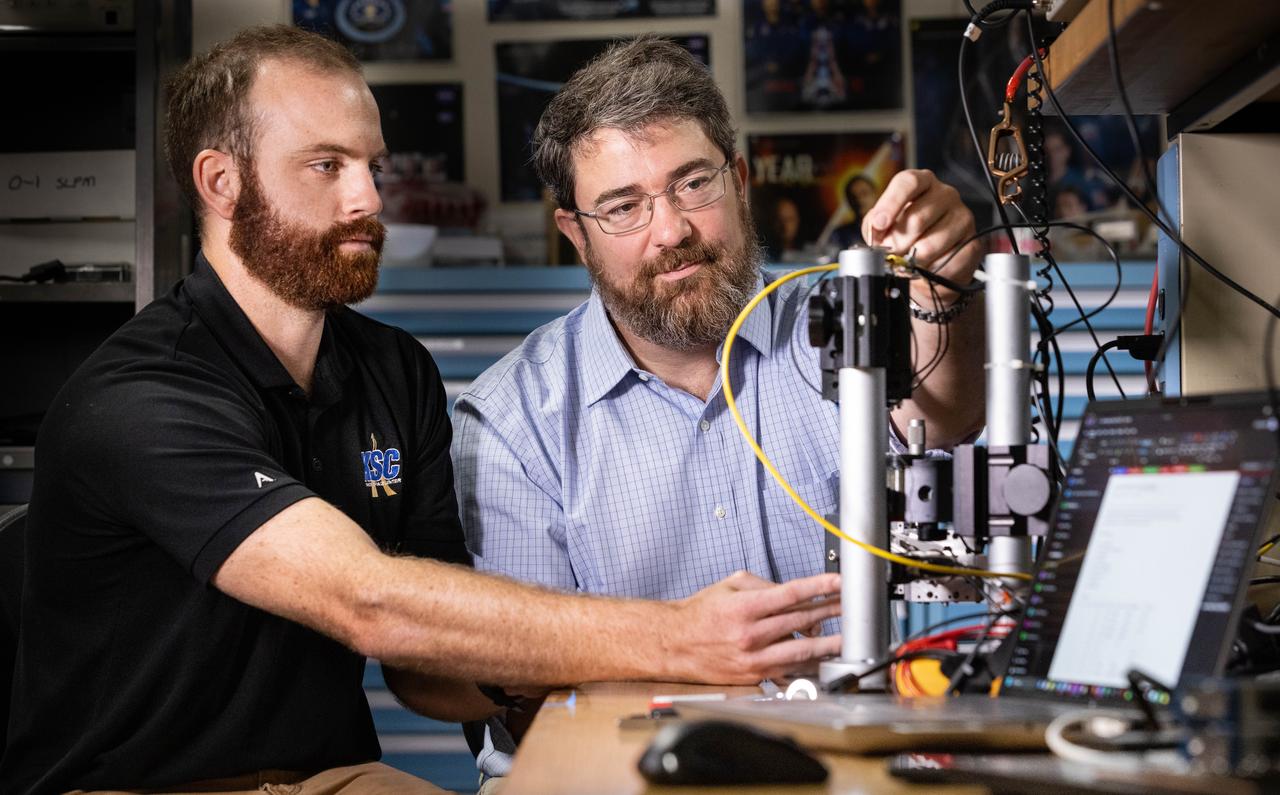
Left to right, Stefan Tomovic from the Engineering Directorate at NASA’s Kennedy Space Center in Florida and Christopher Biagi from the agency’s Exploration Research & Technology Program evaluate pressure transducers for NASA’s Engineering and Safety Center on Wednesday, Aug. 20, 2025. This probe is designed to improve the detection of thruster pressure sensor anomalies for the agency’s Commercial Crew Program.
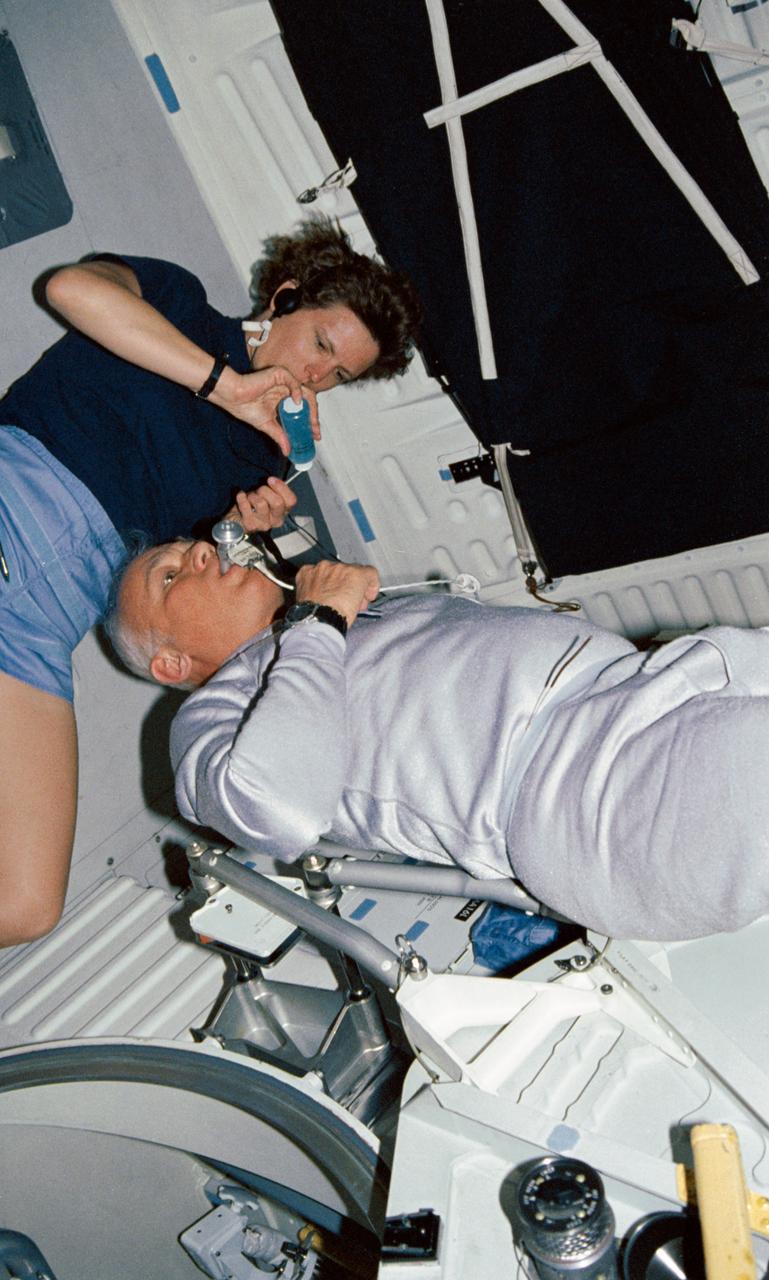
STS031-04-002 (24-29 April 1990) --- Astronauts Kathryn D. Sullivan and Bruce McCandless II, mission specialists, work together to perform one of the mission's medical experiments. The experiment is Detailed Supplementary Objective (DSO) 462, Non invasive Estimation of Central Venous Pressure During Spaceflight. Sullivan applies a gel substance to a transducer which will be placed on McCandless' jugular vein to collect the sought data. The cable links to a data recorder.
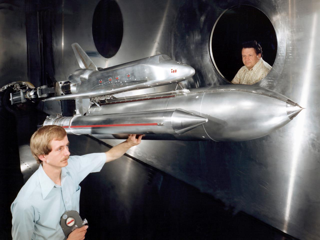
Technicians examine a scale model of the space shuttle used to obtain pressure data during tests in the 10- by 10-Foot Supersonic Wind Tunnel at the National Aeronautics and Space Administration (NASA) Lewis Research Center. Lewis researchers used the 10- by 10 tunnel extensively in the 1970s to study shuttle configurations in order to forecast conditions during an actual flight. These tests included analysis of the solid rocket boosters’ aerodynamics, orbiter forebody angle -of -attack and air speed, base heating for entire shuttle, and engine-out loads. The test seen in this photograph used a 3.5- percent scale aluminum alloy model of the entire launch configuration. The program was designed to obtain aerodynamic pressure data. The tests were part of a larger program to study possible trouble areas for the shuttle’s new Advanced Flexible Reusable Surface Insulation. The researchers obtained aeroacoustic data and pressure distributions from five locations on the model. Over 100 high-temperature pressure transducers were attached to the model. Other portions of the test program were conducted at Lewis’ 8- by 6-Foot Supersonic Wind Tunnel and the 11- by 11-Foot Transonic Wind Tunnel at Ames Research Center.
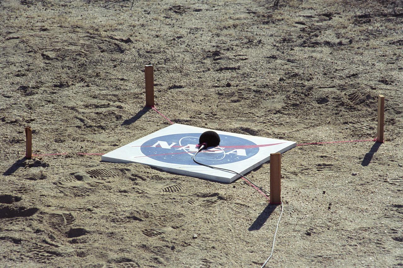
One of many microphones arrayed under the path of the F-5E SSBE (Shaped Sonic Boom Experiment) aircraft to record sonic booms. The SSBE (Shaped Sonic Boom Experiment) was formerly known as the Shaped Sonic Boom Demonstration, or SSBD, and is part of DARPA's Quiet Supersonic Platform (QSP) program. On August 27, 2003, the F-5E SSBD aircraft demonstrated a method to reduce the intensity of sonic booms.
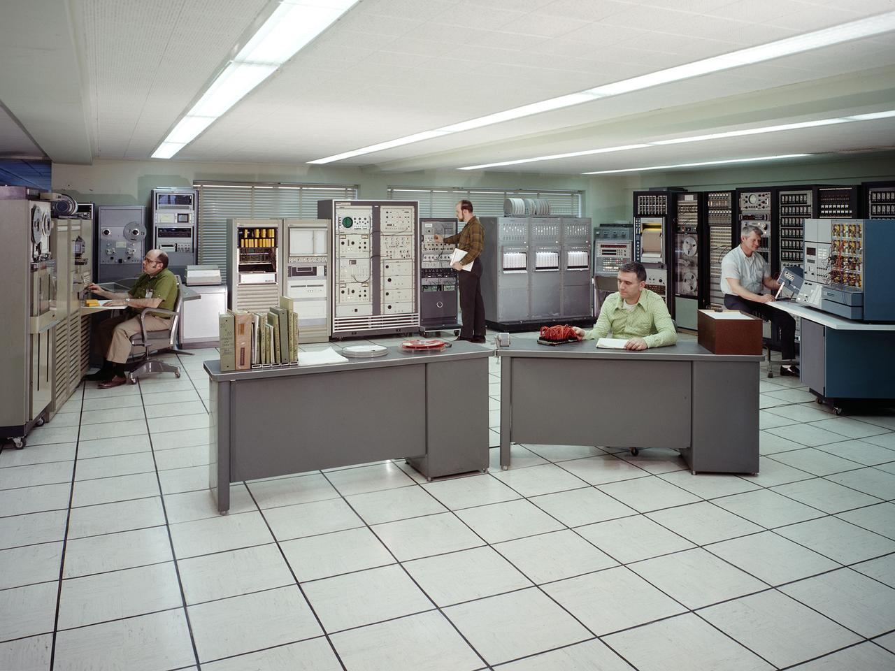
The test data recording equipment located in the office building of the 10-by 10-Foot Supersonic Wind Tunnel at the NASA Lewis Research Center. The data system was the state of the art when the facility began operating in 1955 and was upgraded over time. NASA engineers used solenoid valves to measure pressures from different locations within the test section. Up 48 measurements could be fed into a single transducer. The 10-by 10 data recorders could handle up to 200 data channels at once. The Central Automatic Digital Data Encoder (CADDE) converted this direct current raw data from the test section into digital format on magnetic tape. The digital information was sent to the Lewis Central Computer Facility for additional processing. It could also be displayed in the control room via strip charts or oscillographs. The 16-by 56-foot long ERA 1103 UNIVAC mainframe computer processed most of the digital data. The paper tape with the raw data was fed into the ERA 1103 which performed the needed calculations. The information was then sent back to the control room. There was a lag of several minutes before the computed information was available, but it was exponentially faster than the hand calculations performed by the female computers. The 10- by 10-foot tunnel, which had its official opening in May 1956, was built under the Congressional Unitary Plan Act which coordinated wind tunnel construction at the NACA, Air Force, industry, and universities. The 10- by 10 was the largest of the three NACA tunnels built under the act.