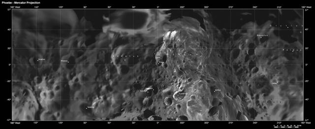
Phoebe: Cartographic Projections Mercator Projection
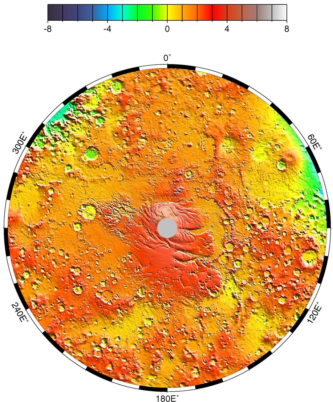
Polar Stereographic Projection
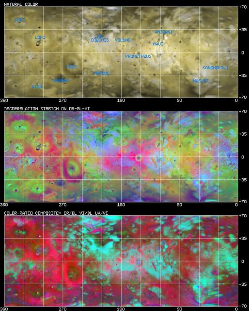
Io: Cylindrical Projection http://photojournal.jpl.nasa.gov/catalog/PIA00401
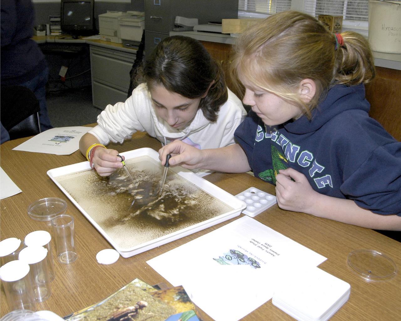
Students participate in the JASON Project's 2004-05 expedition, `Disappearing Wetlands' at SSC, conducting field lab experiments and watching live broadcasts from JASON Expedition Louisiana research sites.
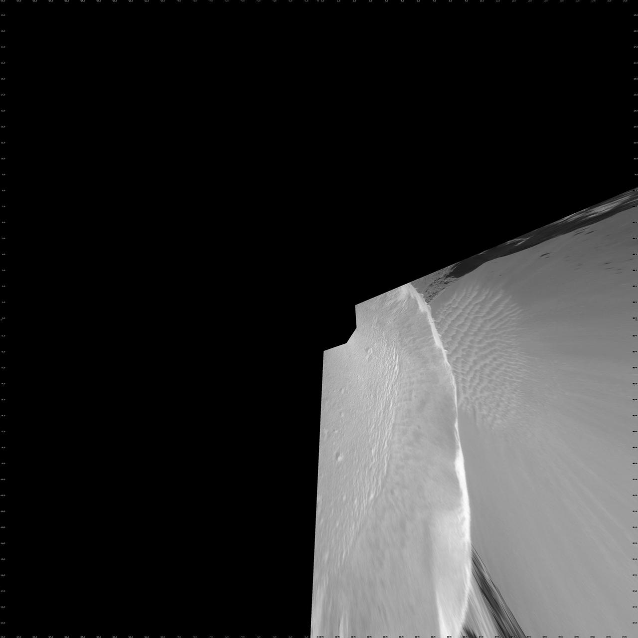
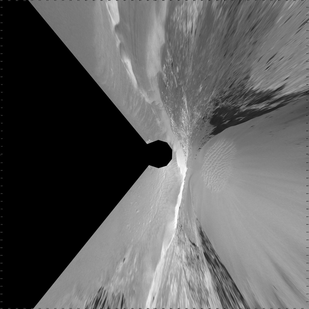
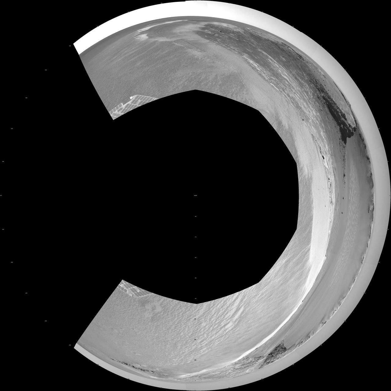
On the Rim of Victoria Crater Vertical Projection
On the Rim of Victoria Crater Polar Projection

Astronaut L. Gordon Cooper, Jr., one of the original seven astronauts for Mercury Project selected by NASA on April 27, 1959. The MA-9 mission, boosted by the Mercury-Atlas launch vehicle, was the last flight of the Mercury Project. The Faith 7 spacecraft orbited the Earth 22 times in 1-1/2 days.

Astronaut Alan B. Shepard, one of the original seven astronauts for Mercury Project selected by NASA on April 27, 1959. The Freedom 7 spacecraft boosted by Mercury-Redstone vehicle for the MR-3 mission made the first marned suborbital flight and Astronaut Shepard became the first American in space.

Astronaut John H. Glenn, one of the original seven astronauts for Mercury Project selected by NASA on April 27, 1959. The MA-6 mission, boosted by the Mercury-Atlas vehicle, was the first manned orbital launch by the United States, and carried Astronaut Glenn aboard the Friendship 7 spacecraft to orbit the Earth.
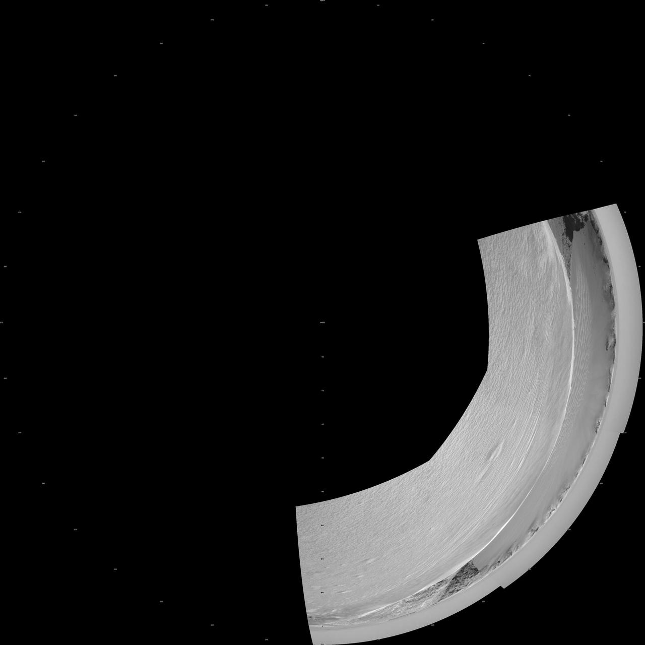
Victoria Crater from Duck Bay Vertical Projection
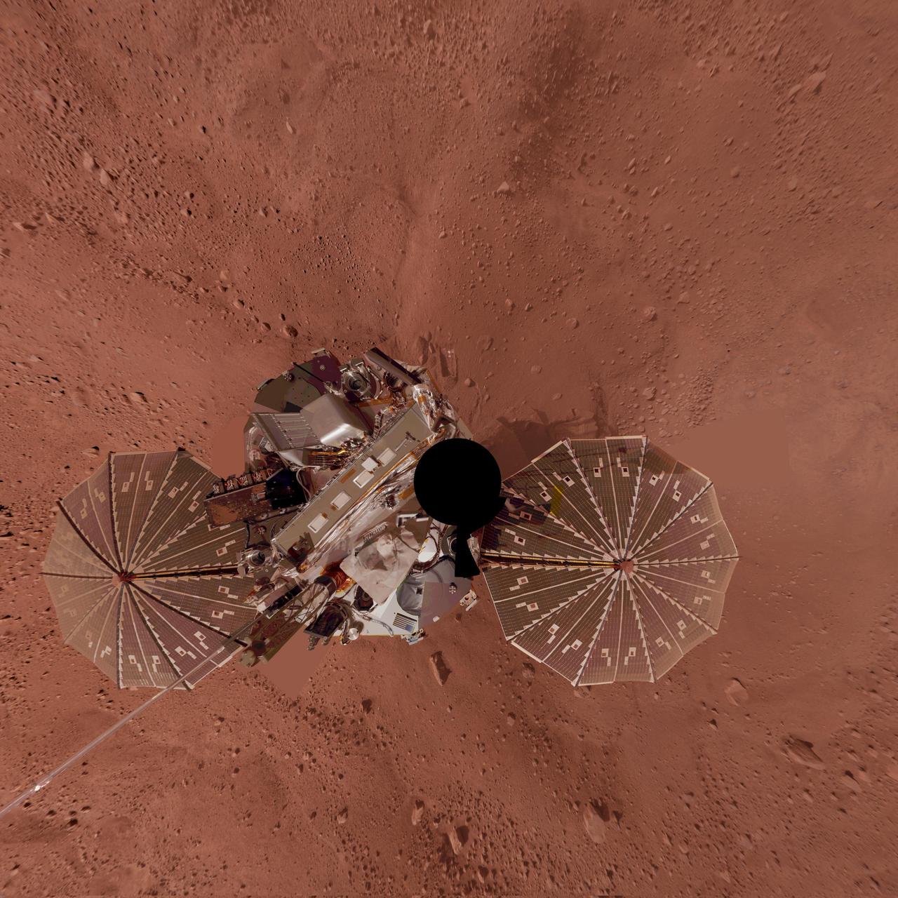
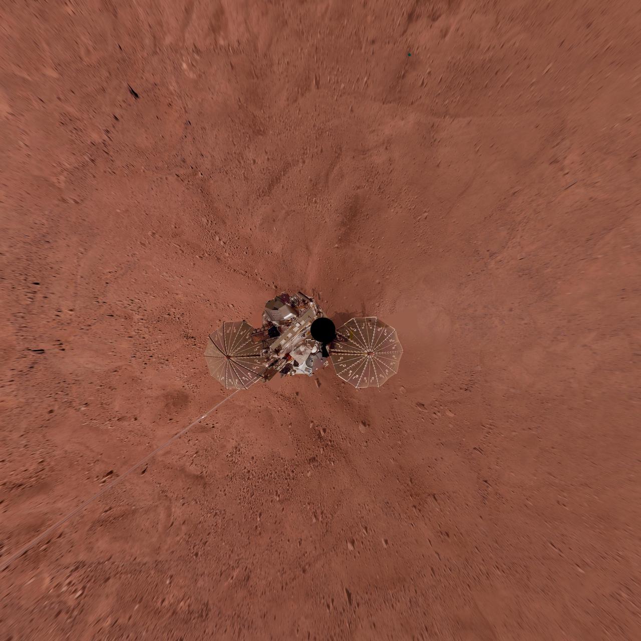
Phoenix Lander Self Portrait on Mars, Vertical Projection
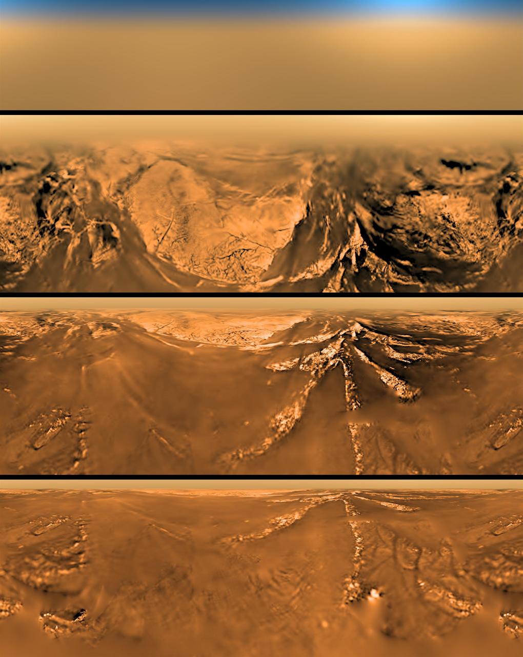
Mercator Projection of Huygens View at Different Altitudes
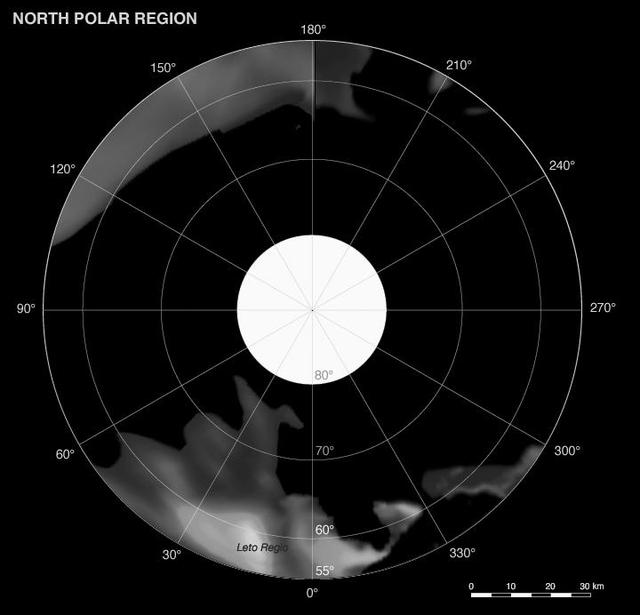
Phoebe: Cartographic Projections North Polar Map
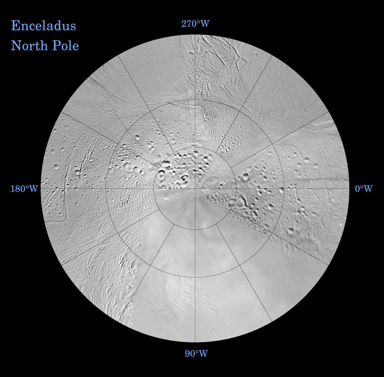
Enceladus: North and South Northern Polar Projection
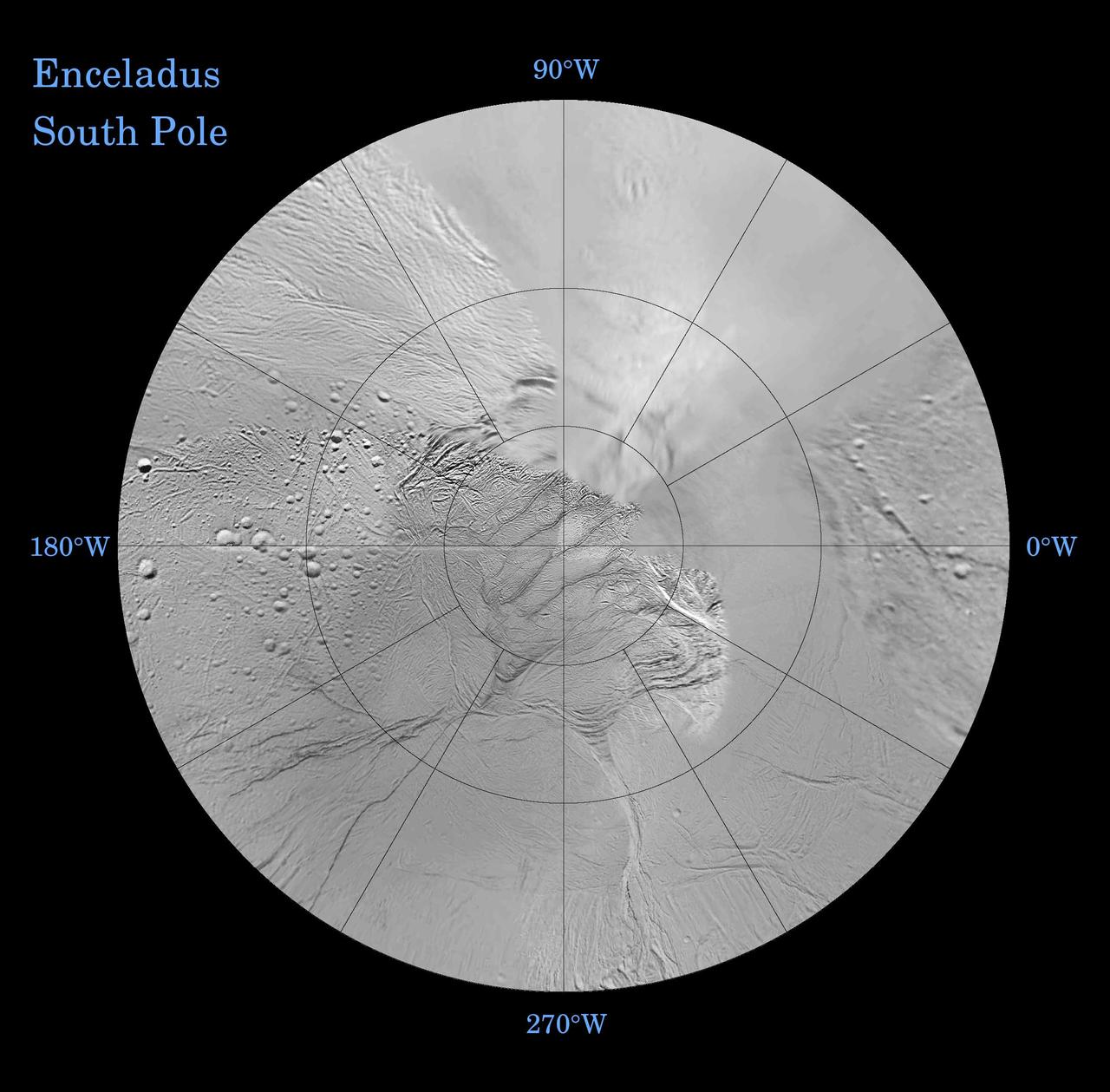
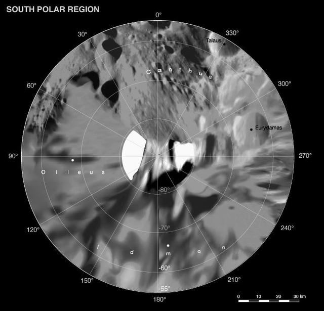
Enceladus: North and South Southern Polar Projection
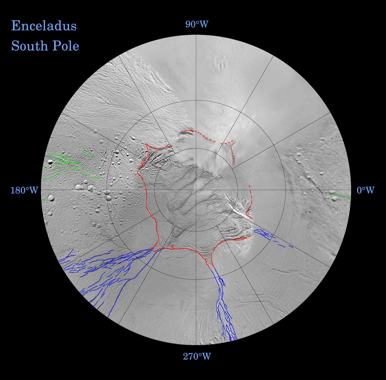
Enceladus: Global Patterns of Fracture Southern Polar Projection
Phoebe: Cartographic Projections South Polar Map
Phoenix Lander on Mars with Surrounding Terrain, Vertical Projection
Lambert Equal-Area Projection of Pole-to-Equator
Victoria Crater from Duck Bay Polar Projection
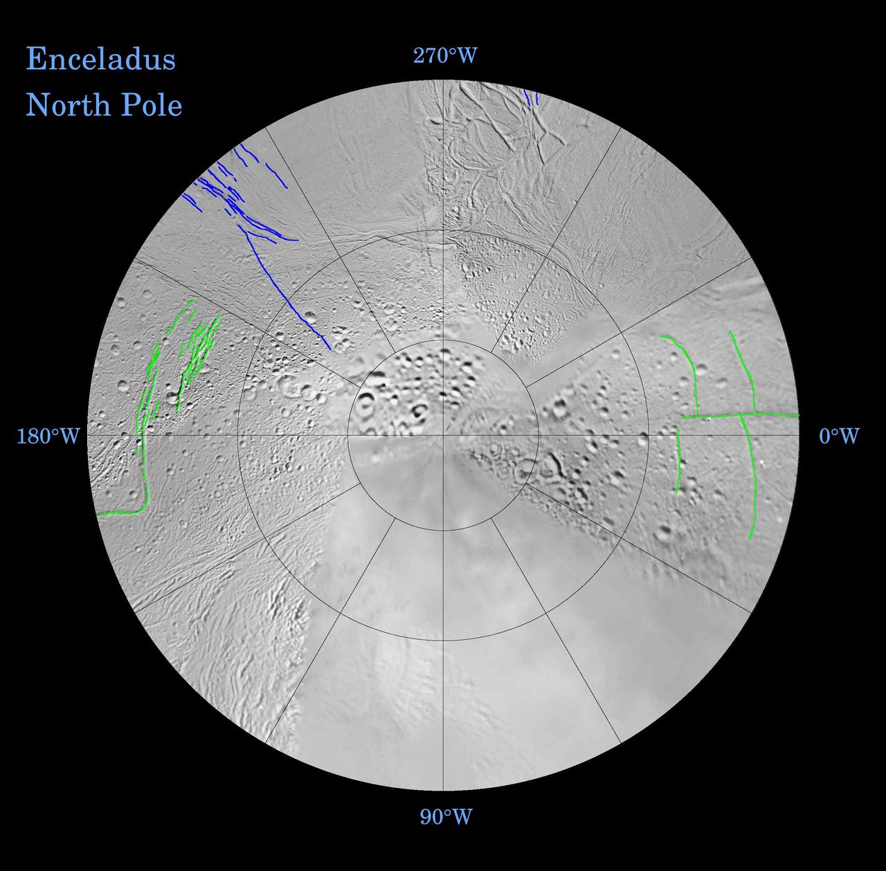
Enceladus: Global Patterns of Fracture Northern Polar Projection

Christopher Kraft, flight director during Project Mercury, works at his console inside the Flight Control area at Mercury Mission Control.
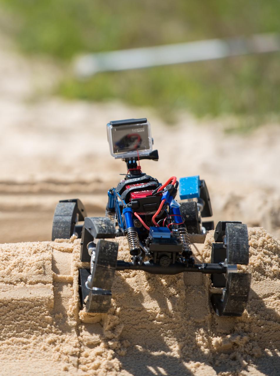
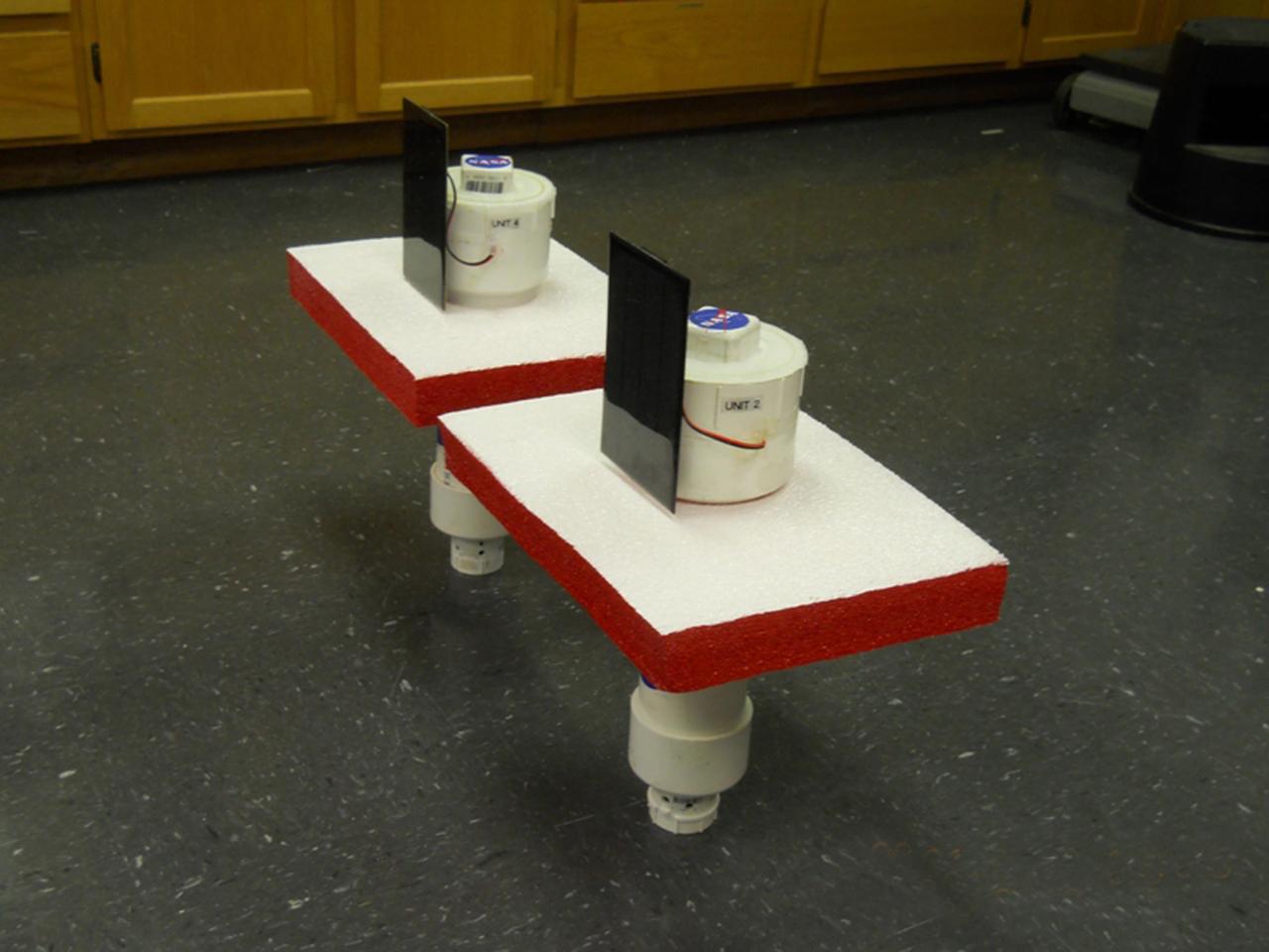
Toledo, Bowser and Scott High School Students, Mars and Moon Wheel, Engineering Design Project, Hardware Test on the Dunes

The original seven astronauts for the Mercury Project pose in front of an Air Force Jet. From left to right: Scott Carpenter, L. Gordon Cooper, John H. Glenn, Virgil I. Gus Grissom, Walter M. Wally Schirra, Alan B. Shepard, and Donald K. Deke Slayton.

Astronaut Virgil I. "Gus" Grissom, one of the original seven astronauts for Mercury Project selected by NASA on April 27, 1959. The MR-4 mission, boosted by the Mercury-Redstone vehicle, made the second marned suborbital flight. The capsule, Liberty Bell 7, sank into the sea after the splashdown.

Astronaut Walter M. "Wally" Schirra, one of the original seven astronauts for Mercury Project selected by NASA on April 27, 1959. The MA-8 (Mercury-Atlas) mission with Sigma 7 spacecraft was the third marned orbital flight by the United States, and made the six orbits in 9-1/4 hours.
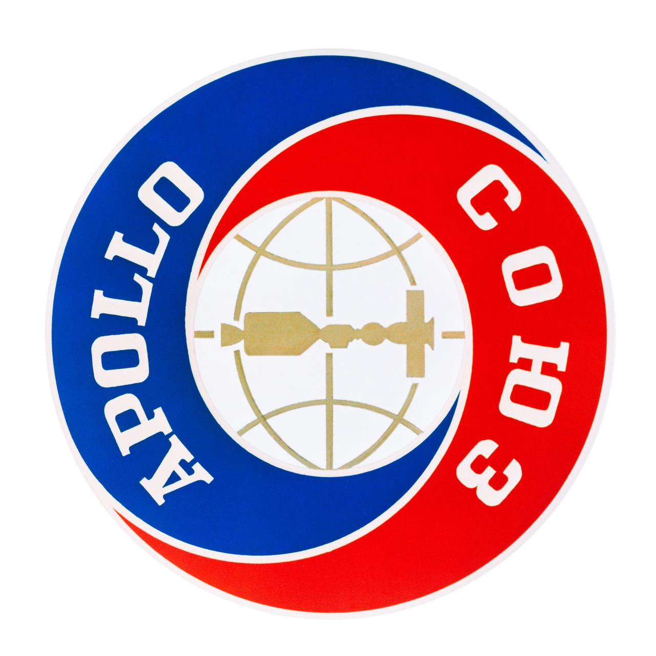
S74-17843 (March 1974) --- This is the official emblem of the Apollo-Soyuz Test Project chosen by NASA and the Soviet Academy of Sciences. The joint U.S.-USSR space mission is scheduled to be flown in July 1975. Of circular design, the emblem has the words Apollo in English and Soyuz in Russian around a center disc which depicts the two spacecraft docked together in Earth orbit. The Apollo-Soyuz Test Project will be carried out by a Soviet Soyuz spacecraft and a U.S. Apollo spacecraft which will rendezvous and dock in orbit. Soyuz and Apollo will remain docked for as long as two days in which period, the three Apollo astronauts will enter Soyuz and the two Soyuz cosmonauts will visit Apollo via a docking module. The Russian word "soyuz" means "union" in English.
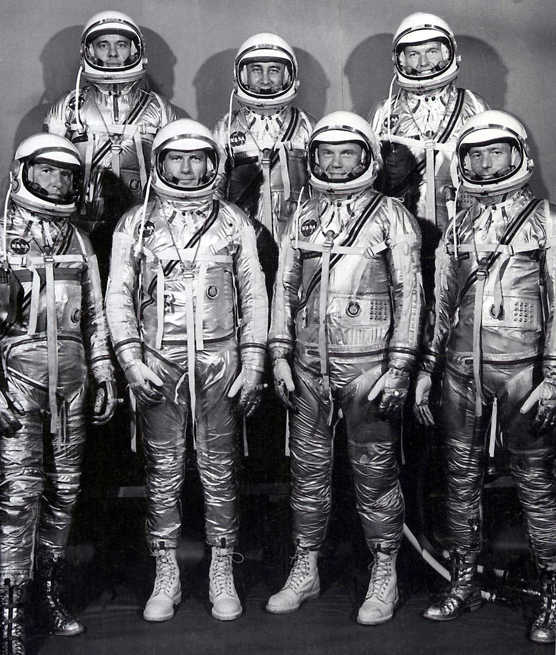
The group portrait of the original seven astronauts for the Mercury Project. NASA selected its first seven astronauts on April 27, 1959. Left to right at front: Walter M. Wally Schirra, Donald K. Deke Slayton, John H. Glenn, Jr., and Scott Carpenter. Left to right at rear: Alan B. Shepard, Virgil I. Gus Grissom, and L. Gordon Cooper, Jr.
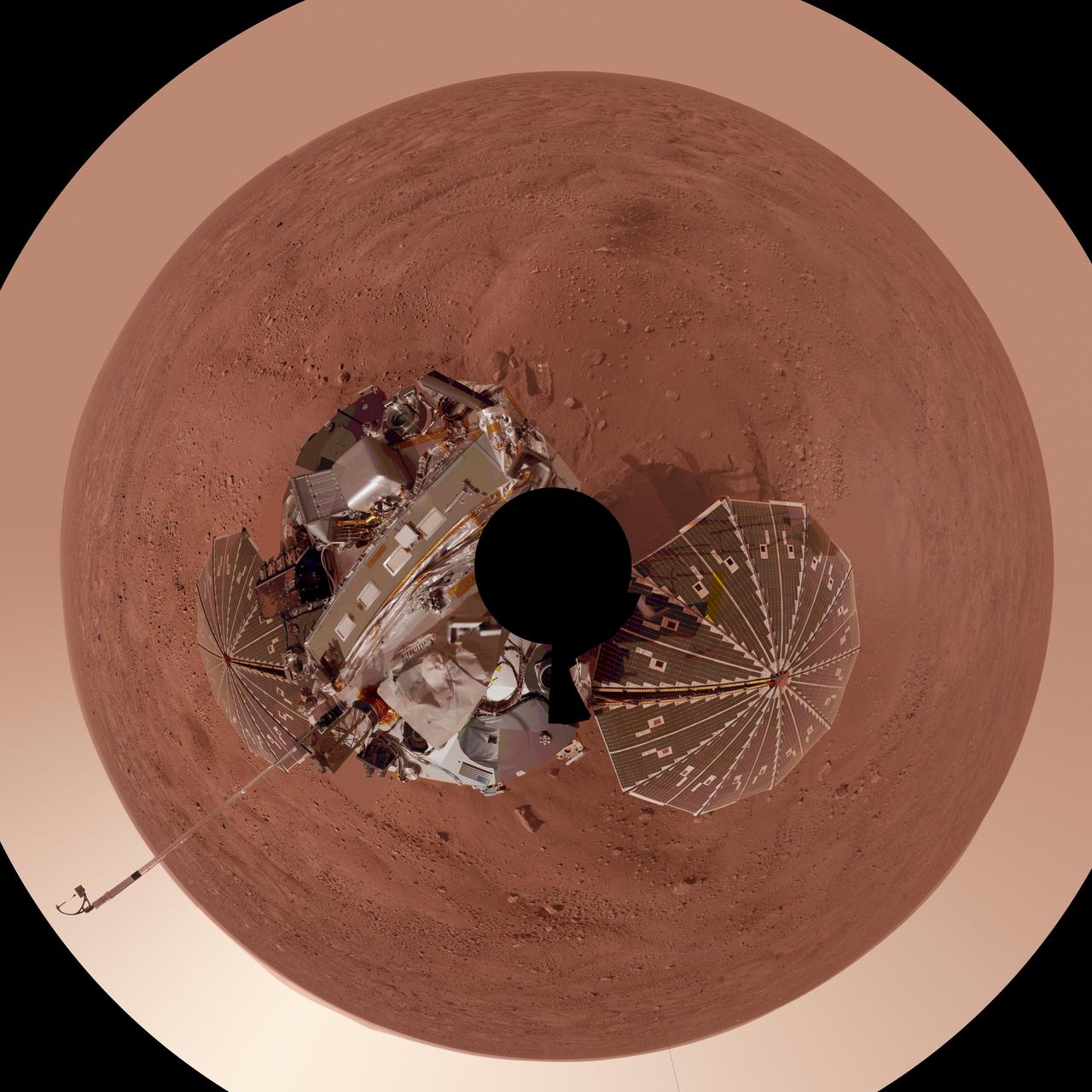
This view is a polar projection that combines more than 500 exposures taken by the Surface Stereo Imager camera on NASA Mars Phoenix Lander and projects them as if looking down from above.
The first flown test vehicle of NASA Low-Density Supersonic Decelerator project relaxes aboard the recovery vessel Kahana.
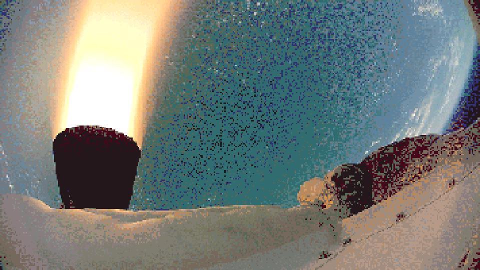
This frame from a video clip shows rockets fired by the test vehicle for NASA Low-Density Supersonic Decelerator project.
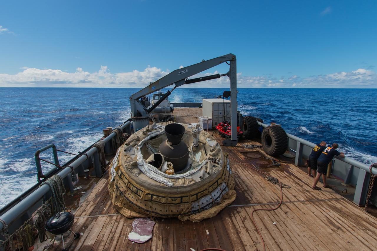
The first flown test vehicle of NASA Low-Density Supersonic Decelerator project relaxes aboard the recovery vessel Kahana.

AST-05-263 (17-18 July 1975) --- The Apollo-Soyuz Test Project (ASTP) Commemorative Plaque is assembled in the Soviet Soyuz Orbital Module during the joint U.S.-USSR Apollo-Soyuz Test Project docking mission in Earth orbit. The plaque is written both in English and Russian.

Gareth Edwards, film director, Rogue One: A Star Wars Story, speaks on a panel after a showing of the Project Mars Competition's short films and the Mars series, Monday, November 5, 2018 at National Geographic Society Headquarters in Washington. Photo Credit: (NASA/Aubrey Gemignani)
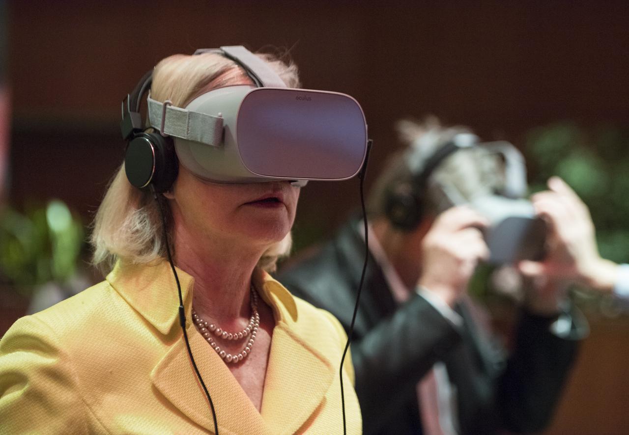
A guest uses some virtual reality viewers before a showing of the Project Mars Competition's short films winners and the Mars series, Monday, November 5, 2018 at National Geographic Society Headquarters in Washington. Photo Credit: (NASA/Aubrey Gemignani)

Chris Davenport, Washington Post space reporter, moderates a panel after a showing of the Project Mars Competition's short films and the Mars series, Monday, November 5, 2018 at National Geographic Society Headquarters in Washington. Photo Credit: (NASA/Aubrey Gemignani)

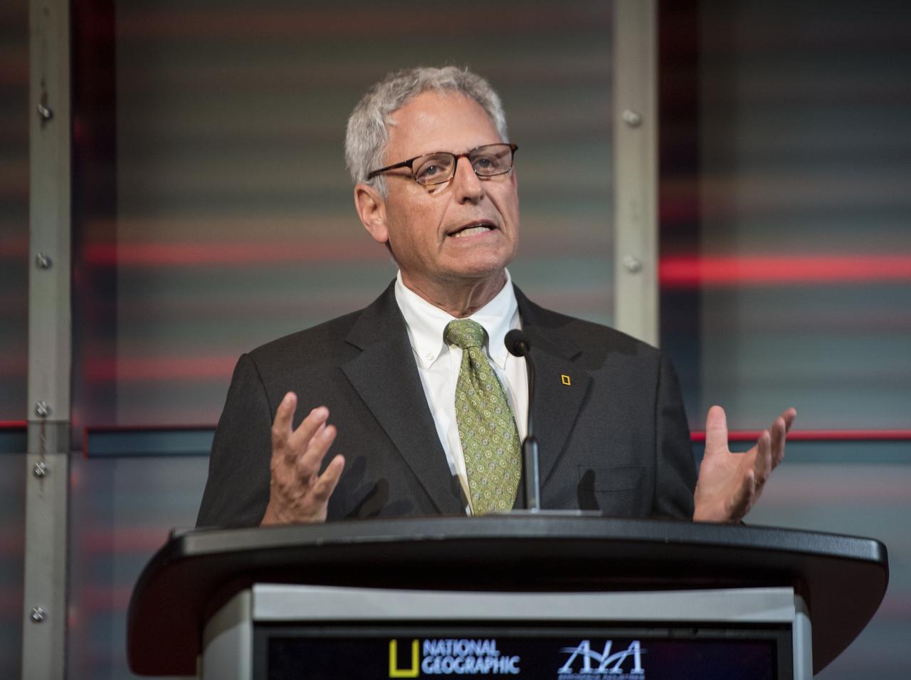
Dr. Stephen Petranek, MARS scientific advisor and co-executive producer speaks on a panel after a showing of the Project Mars Competition's short films and the Mars series, Monday, November 5, 2018 at National Geographic Society Headquarters in Washington. Photo Credit: (NASA/Aubrey Gemignani)

Eric Fanning, AIA President and CEO speaks before a showing of the Project Mars Competition's short films winners and the Mars series, Monday, November 5, 2018 at National Geographic Society Headquarters in Washington. Photo Credit: (NASA/Aubrey Gemignani)
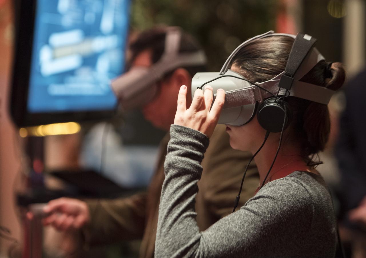
A guest uses some virtual reality viewers before a showing of the Project Mars Competition's short films winners and the Mars series, Monday, November 5, 2018 at National Geographic Society Headquarters in Washington. Photo Credit: (NASA/Aubrey Gemignani)

Ellen Stofan, director, Smithsonian National Air and Space Museum, speaks on a panel after a showing of the Project Mars Competition's short films and the Mars series, Monday, November 5, 2018 at National Geographic Society Headquarters in Washington. Photo Credit: (NASA/Aubrey Gemignani)

Christyl Johnson, deputy director for technology and research investments, NASA Goddard Space Flight Center, second from right, speaks on a panel after a showing of the Project Mars Competition's short films and the Mars series, Monday, November 5, 2018 at National Geographic Society Headquarters in Washington. Photo Credit: (NASA/Aubrey Gemignani)

Ellen Stofan, director, Smithsonian National Air and Space Museum, speaks on a panel after a showing of the Project Mars Competition's short films and the Mars series, Monday, November 5, 2018 at National Geographic Society Headquarters in Washington. Photo Credit: (NASA/Aubrey Gemignani)
Gary Knell, CEO, National Geographic Partners speaks before a showing of the Project Mars Competition's short films winners and the Mars series, Monday, November 5, 2018 at National Geographic Society Headquarters in Washington. Photo Credit: (NASA/Aubrey Gemignani)
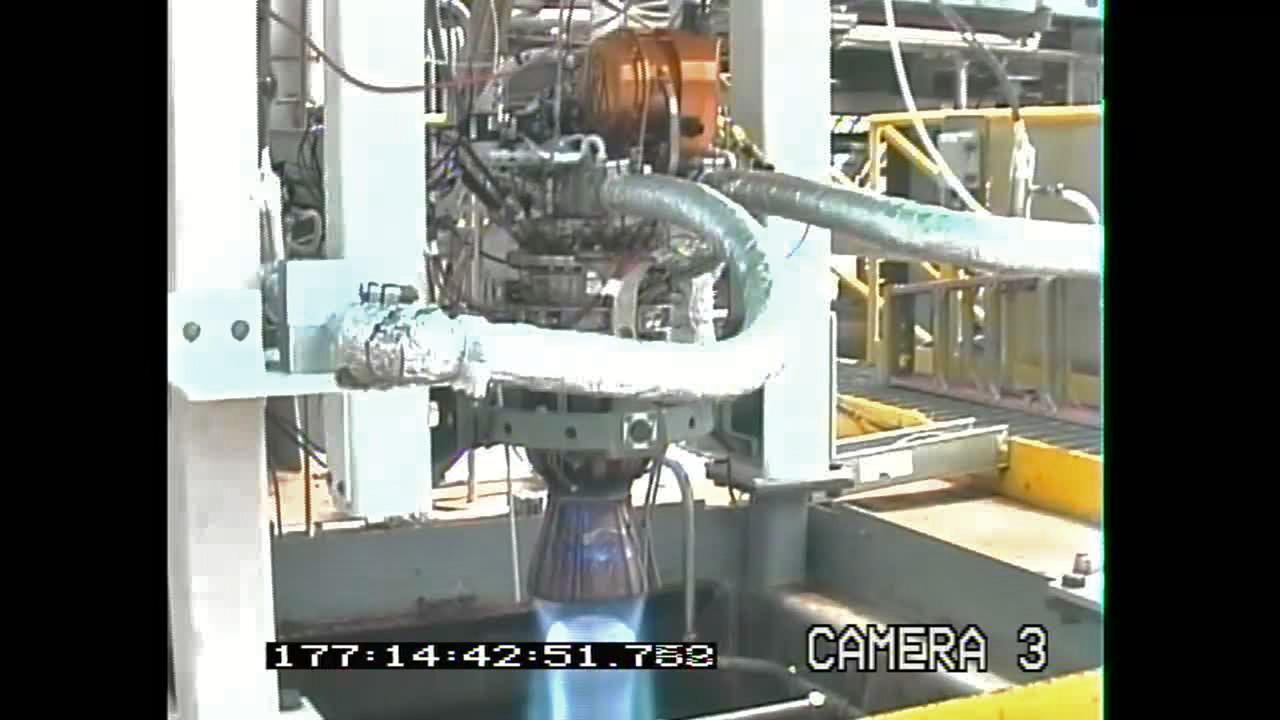
A frame grab from a mounted video camera on the E-3 Test Stand at Stennis Space Center documents testing of the new Project Morpheus engine. The new liquid methane, liquid oxygen engine will power the Morpheus prototype lander, which could one day evolve to carry cargo safely to the moon, asteroids or Mars surfaces.

Project LOLA. Test subject sitting at the controls: Project LOLA or Lunar Orbit and Landing Approach was a simulator built at Langley to study problems related to landing on the lunar surface. It was a complex project that cost nearly 2 million dollars. James Hansen wrote: This simulator was designed to provide a pilot with a detailed visual encounter with the lunar surface the machine consisted primarily of a cockpit, a closed-circuit TV system, and four large murals or scale models representing portions of the lunar surface as seen from various altitudes. The pilot in the cockpit moved along a track past these murals which would accustom him to the visual cues for controlling a spacecraft in the vicinity of the moon. Unfortunately, such a simulation--although great fun and quite aesthetic--was not helpful because flight in lunar orbit posed no special problems other than the rendezvous with the LEM, which the device did not simulate. Not long after the end of Apollo, the expensive machine was dismantled. (p. 379) Ellis J. White wrote in his paper, Discussion of Three Typical Langley Research Center Simulation Programs : A typical mission would start with the first cart positioned on model 1 for the translunar approach and orbit establishment. After starting the descent, the second cart is readied on model 2 and, at the proper time, when superposition occurs, the pilot s scene is switched from model 1 to model 2. then cart 1 is moved to and readied on model 3. The procedure continues until an altitude of 150 feet is obtained. The cabin of the LM vehicle has four windows which represent a 45 degree field of view. The projection screens in front of each window represent 65 degrees which allows limited head motion before the edges of the display can be seen. The lunar scene is presented to the pilot by rear projection on the screens with four Schmidt television projectors. The attitude orientation of the vehicle is represented by changing the lunar scene through the portholes determined by the scan pattern of four orthicons. The stars are front projected onto the upper three screens with a four-axis starfield generation (starball) mounted over the cabin and there is a separate starball for the low window. -- Published in James R. Hansen, Spaceflight Revolution: NASA Langley Research Center From Sputnik to Apollo, (Washington: NASA, 1995), p. 379 Ellis J. White, Discussion of Three Typical Langley Research Center Simulation Programs, Paper presented at the Eastern Simulation Council (EAI s Princeton Computation Center), Princeton, NJ, October 20, 1966.
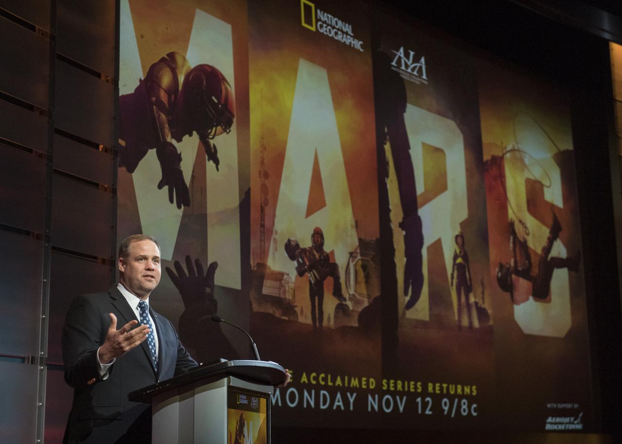
NASA Administrator Jim Bridenstine gives keynote remarks before a showing of the Project Mars Competition's short films and the Mars series, Monday, November 5, 2018 at National Geographic Society Headquarters in Washington. Photo Credit: (NASA/Aubrey Gemignani)

NASA Administrator Jim Bridenstine gives keynote remarks before a showing of the Project Mars Competition's short films and the Mars series, Monday, November 5, 2018 at National Geographic Society Headquarters in Washington. Photo Credit: (NASA/Aubrey Gemignani)
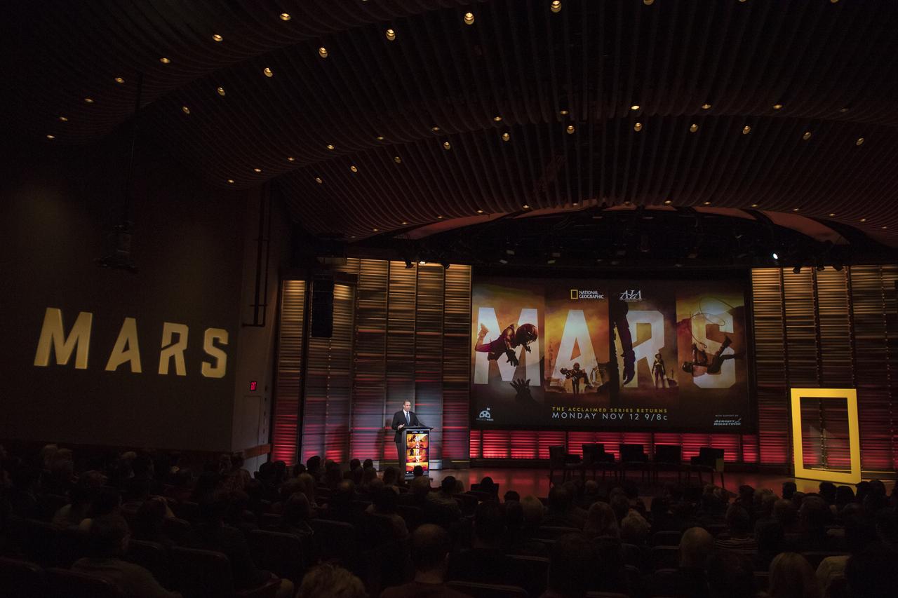
NASA Administrator Jim Bridenstine gives keynote remarks before a showing of the Project Mars Competition's short films and the Mars series, Monday, November 5, 2018 at National Geographic Society Headquarters in Washington. Photo Credit: (NASA/Aubrey Gemignani)
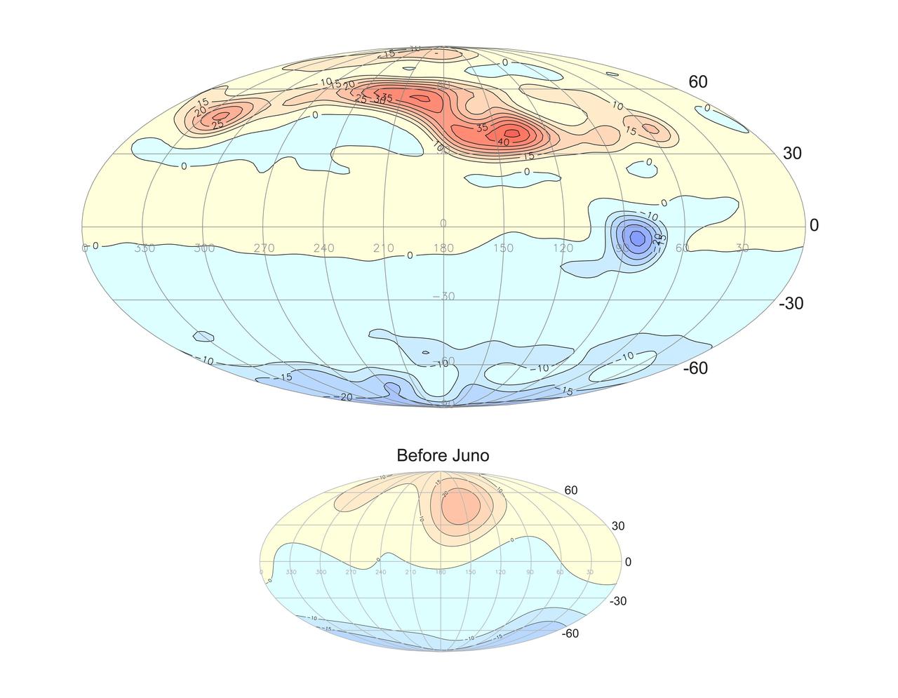
This projection of the radial magnetic field of Jupiter (top) uses a new magnetic field model based on data from Juno's orbits during its prime mission. Magnetic field lines emerge from yellow and red regions and enter the planet in the blue regions. The new model represents a vast improvement in spatial resolution compared to prior knowledge (bottom) provided by earlier missions, including Pioneer 10 and 11, Voyager 1 and 2, Ulysses, and Galileo. https://photojournal.jpl.nasa.gov/catalog/PIA25040
DRIFTER sensor devices were designed by the Applied Science and Technology Project Office as inexpensive tools that can be used for science projects in local schools. The devices transmit information about water temperature and conductivity for use by Gulf Coast researchers. The DRIFTER project began as an effort to help Gulf Coast oyster fishermen dealing with the effects of fresh water intrusion.
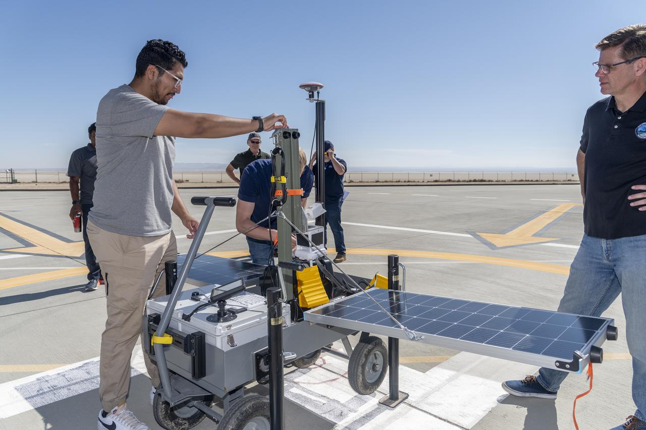
NASA operations engineer Daniel Velasquez, left, is reviewing the Mobile Vertipad Sensor Package system as part of the Air Mobility Pathways test project at NASA's Armstrong Flight Research Center in Edwards, California on October 17, 2023. The portable system allows Advanced Air Mobility researchers to test and evaluate several factors involved in monitoring takeoff and landing conditions at vertipad sites. "Vertipads" or "vertiports" will be where future air taxis will land and take off to transport passengers.
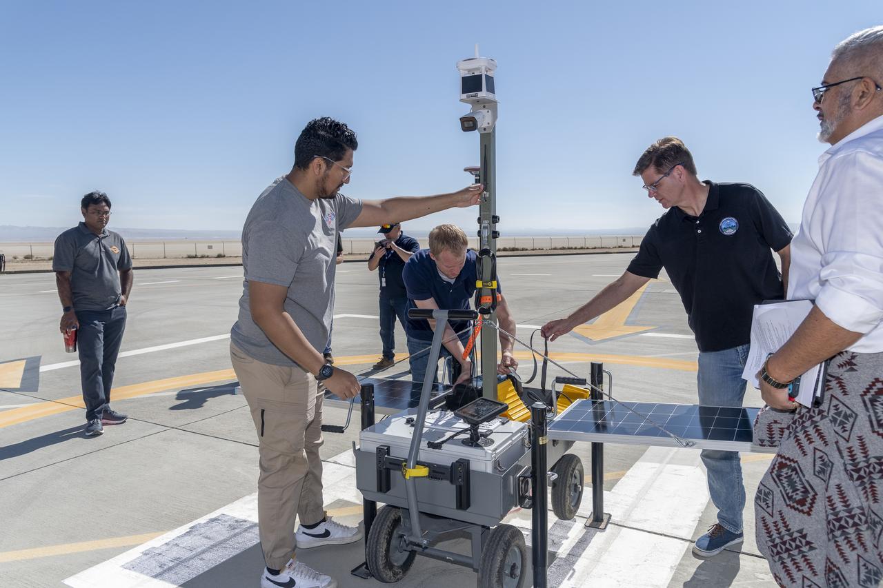
NASA operations engineer Daniel Velasquez, left, is reviewing the Mobile Vertipad Sensor Package system as part of the Air Mobility Pathways test project at NASA's Armstrong Flight Research Center in Edwards, California on October 17, 2023. The portable system allows Advanced Air Mobility researchers to test and evaluate several factors involved in monitoring takeoff and landing conditions at vertipad sites. "Vertipads" or "vertiports" will be where future air taxis will land and take off to transport passengers.
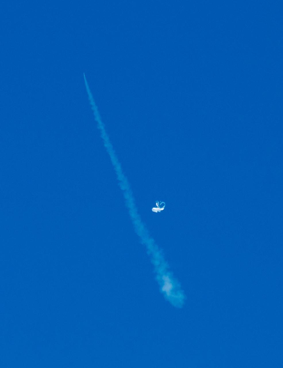
NASA Low-Density Supersonic Decelerator project, will test an inflatable decelerator and a parachute at high altitudes and speeds over the Pacific Missile Range this June.
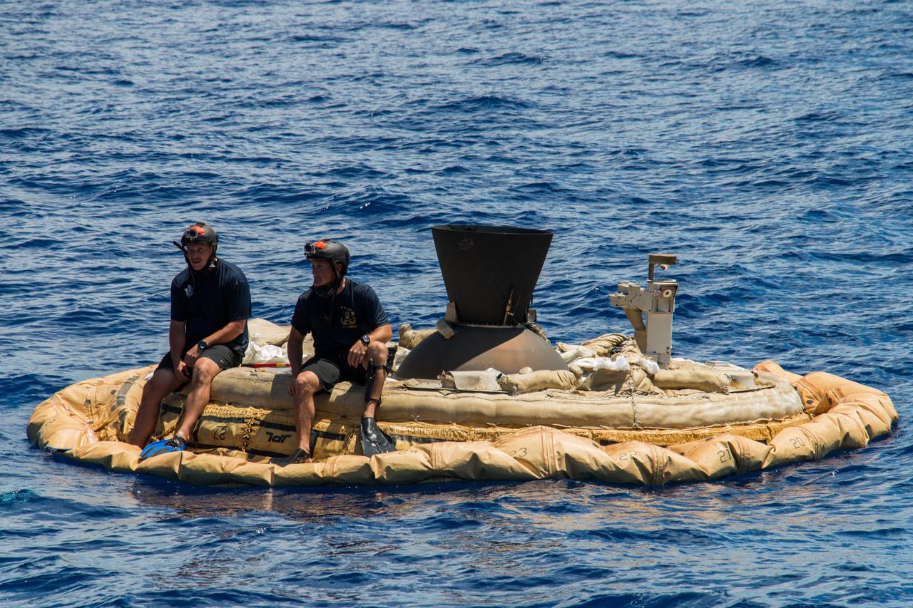
Two members of the Navy Explosive Ordinance Disposal team perch on the test vehicle used in the first flight of NASA Low-density Supersonic Decelerator project.

Sled tests will allow NASA Low-Density Supersonic Decelerator Project, or LDSD, to test inflatable and parachute decelerators to slow spacecraft prior to landing.
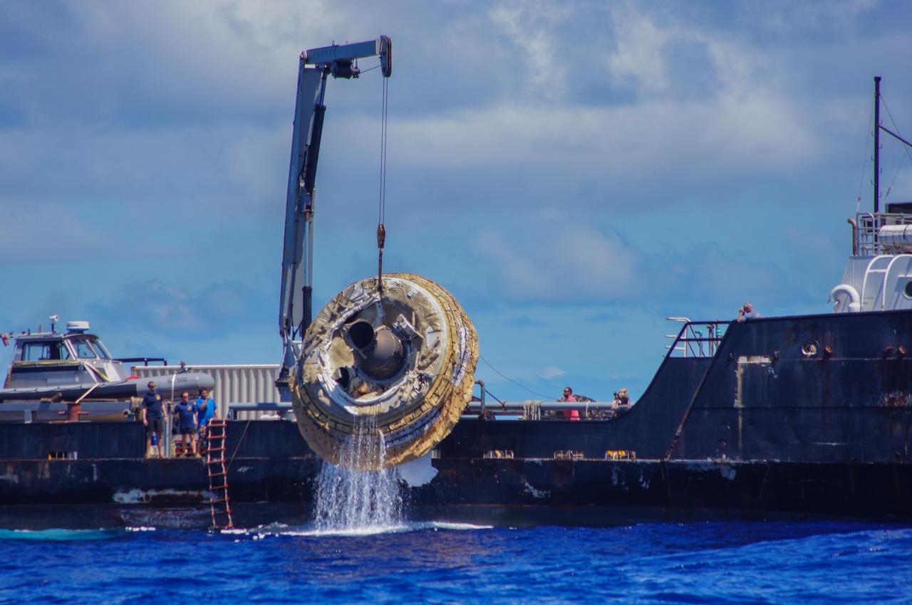
Hours after its successful engineering flight, the first test vehicle for NASA Low-Density Supersonic Decelerator project is lifted aboard the recovery vessel Kahana.

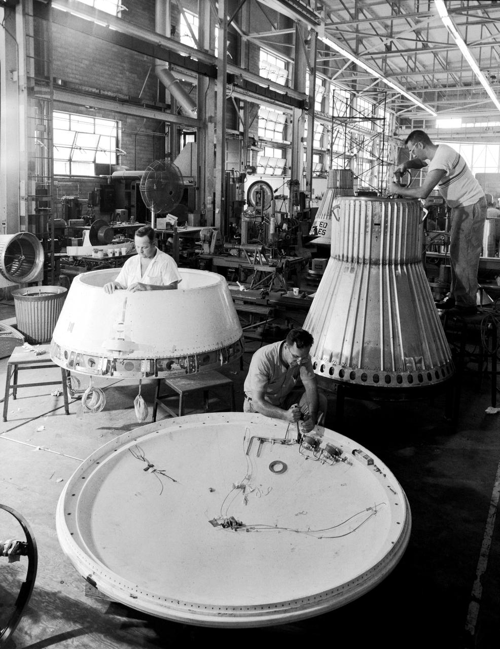
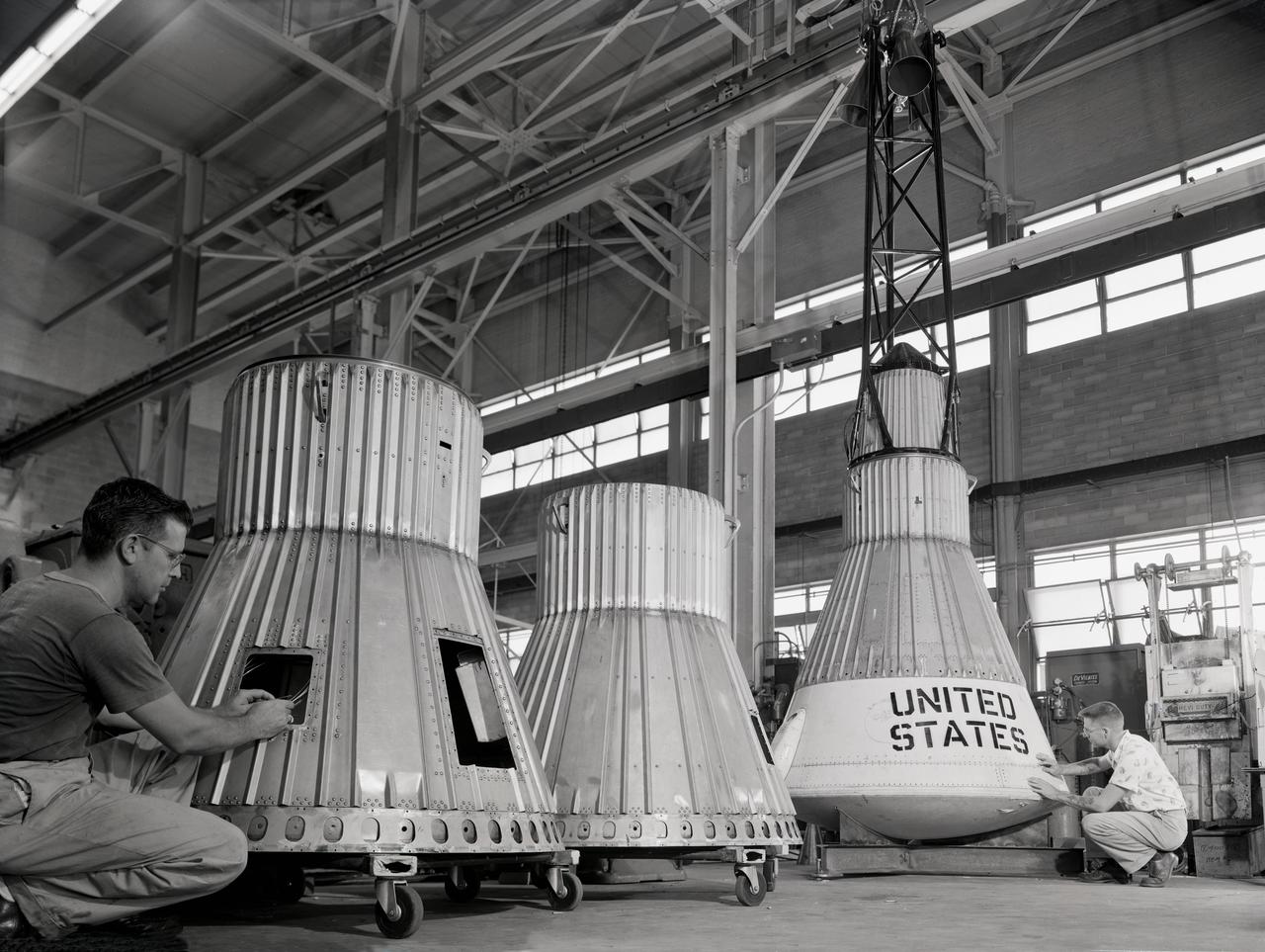
Assembling the Little Joe capsules. The capsules were manufactured in-house by Langley technicians. Three capsules are shown here in various stages of assembly. The escape tower and rocket motors shown on the completed capsule would be removed before shipping and finally assembly for launching at Wallops Island. Joseph Shortal wrote (vol. 3, p. 32): Design of the Little Joe capsules began at Langley before McDonnell started on the design of the Mercury capsule and was, therefore, a separate design. Although it was not designed to carry a man, it did have to carry a monkey. It had to meet the weight and center of gravity requirements of Mercury and withstand the same aerodynamic loads during the exit trajectory. Although in comparison with the overall Mercury Project, Little Joe was a simple undertaking, the fact that an attempt was made to condense a normal two-year project into a 6-month one with in house labor turned it into a major undertaking for Langley. Project Mercury: Little Joe: Boilerplate Mercury spacecraft undergo fabrication at the shops of the Langley Research Center. They will launched atop Little Joe rockets to test the spacecraft recovery systems. -- Published in Joseph A. Shortal, History of Wallops Station: Origins and Activities Through 1949, (Wallops Island, VA: National Aeronautics and Space Administration, Wallops Station, nd), Comment Edition. L59-4947 Technicians prepare a Little Joe launch vehicle prototype for the Mercury space program, 1959. Photograph published in Winds of Change, 75th Anniversary NASA publication, page 76, by James Schultz
Assembling the Little Joe capsules. The capsules were manufactured in-house by Langley technicians. Three capsules are shown here in various stages of assembly. The escape tower and rocket motors shown on the completed capsule would be removed before shipping and finally assembly for launching at Wallops Island. Joseph Shortal wrote (vol. 3, p. 32): Design of the Little Joe capsules began at Langley before McDonnell started on the design of the Mercury capsule and was, therefore, a separate design. Although it was not designed to carry a man, it did have to carry a monkey. It had to meet the weight and center of gravity requirements of Mercury and withstand the same aerodynamic loads during the exit trajectory. Although in comparison with the overall Mercury Project, Little Joe was a simple undertaking, the fact that an attempt was made to condense a normal two-year project into a 6-month one with in house labor turned it into a major undertaking for Langley. Project Mercury: Little Joe: Boilerplate Mercury spacecraft undergo fabrication at the shops of the Langley Research Center. They will launched atop Little Joe rockets to test the spacecraft recovery systems. -- Published in Joseph A. Shortal, History of Wallops Station: Origins and Activities Through 1949, (Wallops Island, VA: National Aeronautics and Space Administration, Wallops Station, nd), Comment Edition. L59-4947 Technicians prepare a Little Joe launch vehicle prototype for the Mercury space program, 1959. Photograph published in Winds of Change, 75th Anniversary NASA publication, page 76, by James Schultz
Assembling the Little Joe capsules. The capsules were manufactured in-house by Langley technicians. Three capsules are shown here in various stages of assembly. The escape tower and rocket motors shown on the completed capsule would be removed before shipping and finally assembly for launching at Wallops Island. Joseph Shortal wrote (vol. 3, p. 32): Design of the Little Joe capsules began at Langley before McDonnell started on the design of the Mercury capsule and was, therefore, a separate design. Although it was not designed to carry a man, it did have to carry a monkey. It had to meet the weight and center of gravity requirements of Mercury and withstand the same aerodynamic loads during the exit trajectory. Although in comparison with the overall Mercury Project, Little Joe was a simple undertaking, the fact that an attempt was made to condense a normal two-year project into a 6-month one with in house labor turned it into a major undertaking for Langley. Project Mercury: Little Joe: Boilerplate Mercury spacecraft undergo fabrication at the shops of the Langley Research Center. They will launched atop Little Joe rockets to test the spacecraft recovery systems. -- Published in Joseph A. Shortal, History of Wallops Station: Origins and Activities Through 1949, (Wallops Island, VA: National Aeronautics and Space Administration, Wallops Station, nd), Comment Edition. L59-4947 Technicians prepare a Little Joe launch vehicle prototype for the Mercury space program, 1959. Photograph published in Winds of Change, 75th Anniversary NASA publication, page 76, by James Schultz

Assembling the Little Joe capsules. The capsules were manufactured in-house by Langley technicians. Three capsules are shown here in various stages of assembly. The escape tower and rocket motors shown on the completed capsule would be removed before shipping and finally assembly for launching at Wallops Island. Joseph Shortal wrote (vol. 3, p. 32): Design of the Little Joe capsules began at Langley before McDonnell started on the design of the Mercury capsule and was, therefore, a separate design. Although it was not designed to carry a man, it did have to carry a monkey. It had to meet the weight and center of gravity requirements of Mercury and withstand the same aerodynamic loads during the exit trajectory. Although in comparison with the overall Mercury Project, Little Joe was a simple undertaking, the fact that an attempt was made to condense a normal two-year project into a 6-month one with in house labor turned it into a major undertaking for Langley. Project Mercury: Little Joe: Boilerplate Mercury spacecraft undergo fabrication at the shops of the Langley Research Center. They will launched atop Little Joe rockets to test the spacecraft recovery systems. -- Published in Joseph A. Shortal, History of Wallops Station: Origins and Activities Through 1949, (Wallops Island, VA: National Aeronautics and Space Administration, Wallops Station, nd), Comment Edition. L59-4947 Technicians prepare a Little Joe launch vehicle prototype for the Mercury space program, 1959. Photograph published in Winds of Change, 75th Anniversary NASA publication, page 76, by James Schultz
Assembling the Little Joe capsules. The capsules were manufactured in-house by Langley technicians. Three capsules are shown here in various stages of assembly. The escape tower and rocket motors shown on the completed capsule would be removed before shipping and finally assembly for launching at Wallops Island. Joseph Shortal wrote (vol. 3, p. 32): Design of the Little Joe capsules began at Langley before McDonnell started on the design of the Mercury capsule and was, therefore, a separate design. Although it was not designed to carry a man, it did have to carry a monkey. It had to meet the weight and center of gravity requirements of Mercury and withstand the same aerodynamic loads during the exit trajectory. Although in comparison with the overall Mercury Project, Little Joe was a simple undertaking, the fact that an attempt was made to condense a normal two-year project into a 6-month one with in house labor turned it into a major undertaking for Langley. Project Mercury: Little Joe: Boilerplate Mercury spacecraft undergo fabrication at the shops of the Langley Research Center. They will launched atop Little Joe rockets to test the spacecraft recovery systems. -- Published in Joseph A. Shortal, History of Wallops Station: Origins and Activities Through 1949, (Wallops Island, VA: National Aeronautics and Space Administration, Wallops Station, nd), Comment Edition. L59-4947 Technicians prepare a Little Joe launch vehicle prototype for the Mercury space program, 1959. Photograph published in Winds of Change, 75th Anniversary NASA publication, page 76, by James Schultz

Assembling the Little Joe capsules. The capsules were manufactured in-house by Langley technicians. Three capsules are shown here in various stages of assembly. The escape tower and rocket motors shown on the completed capsule would be removed before shipping and finally assembly for launching at Wallops Island. Joseph Shortal wrote (vol. 3, p. 32): Design of the Little Joe capsules began at Langley before McDonnell started on the design of the Mercury capsule and was, therefore, a separate design. Although it was not designed to carry a man, it did have to carry a monkey. It had to meet the weight and center of gravity requirements of Mercury and withstand the same aerodynamic loads during the exit trajectory. Although in comparison with the overall Mercury Project, Little Joe was a simple undertaking, the fact that an attempt was made to condense a normal two-year project into a 6-month one with in house labor turned it into a major undertaking for Langley. Project Mercury: Little Joe: Boilerplate Mercury spacecraft undergo fabrication at the shops of the Langley Research Center. They will launched atop Little Joe rockets to test the spacecraft recovery systems. -- Published in Joseph A. Shortal, History of Wallops Station: Origins and Activities Through 1949, (Wallops Island, VA: National Aeronautics and Space Administration, Wallops Station, nd), Comment Edition. L59-4947 Technicians prepare a Little Joe launch vehicle prototype for the Mercury space program, 1959. Photograph published in Winds of Change, 75th Anniversary NASA publication, page 76, by James Schultz
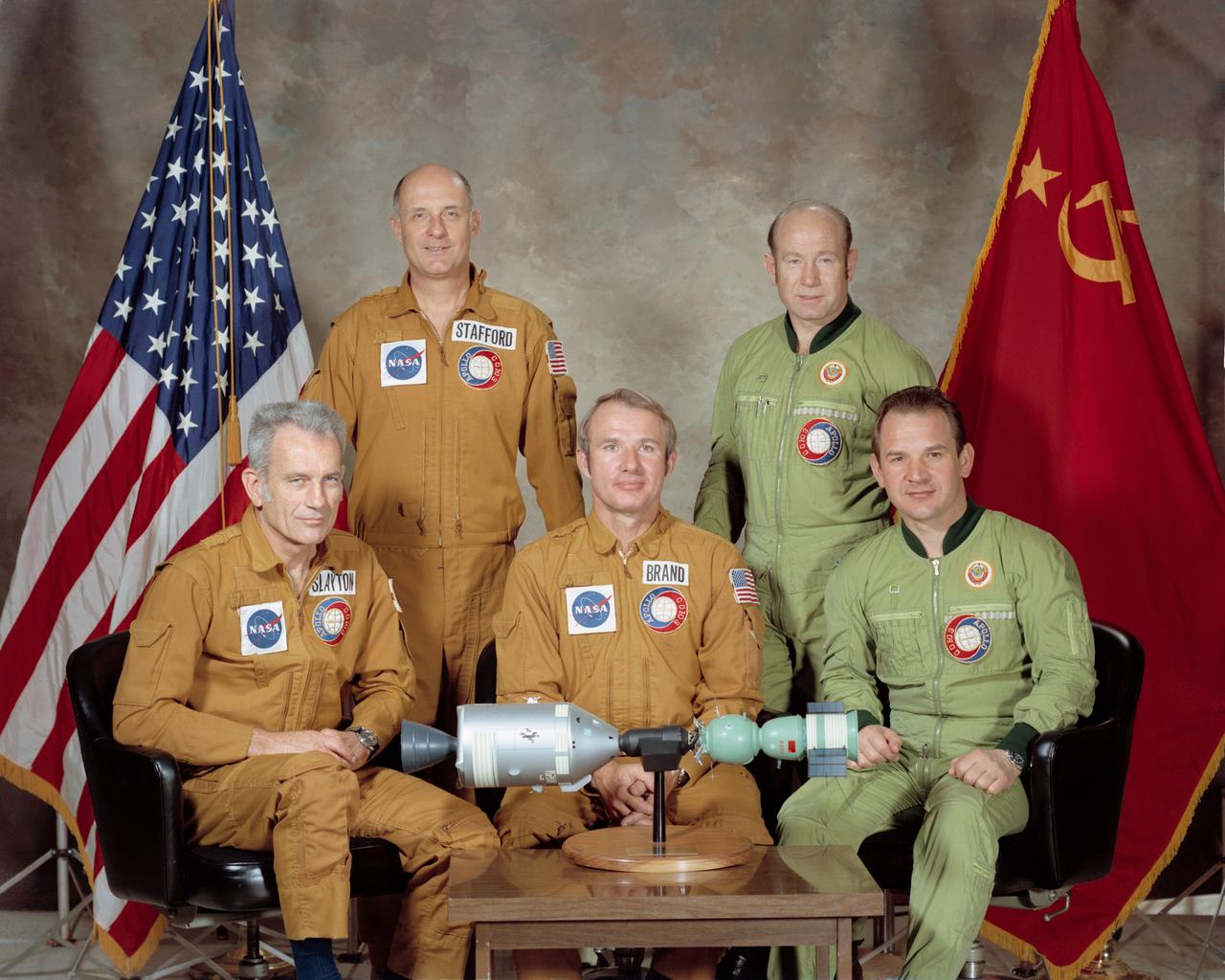
S75-22410 (March 1975) --- These five men compose the two prime crews of the joint United States-USSR Apollo-Soyuz Test Project (ASTP) docking mission in Earth orbit scheduled for July 1975. They are astronaut Thomas P. Stafford (standing on left), commander of the American crew; cosmonaut Aleksey A. Leonov (standing on right), commander of the Soviet crew; astronaut Donald K. Slayton (seated on left), docking module pilot of the American crew; astronaut Vance D. Brand (seated center), command module pilot of the American crew; and cosmonaut Valeriy N. Kubasov (seated on right), engineer on the Soviet crew.
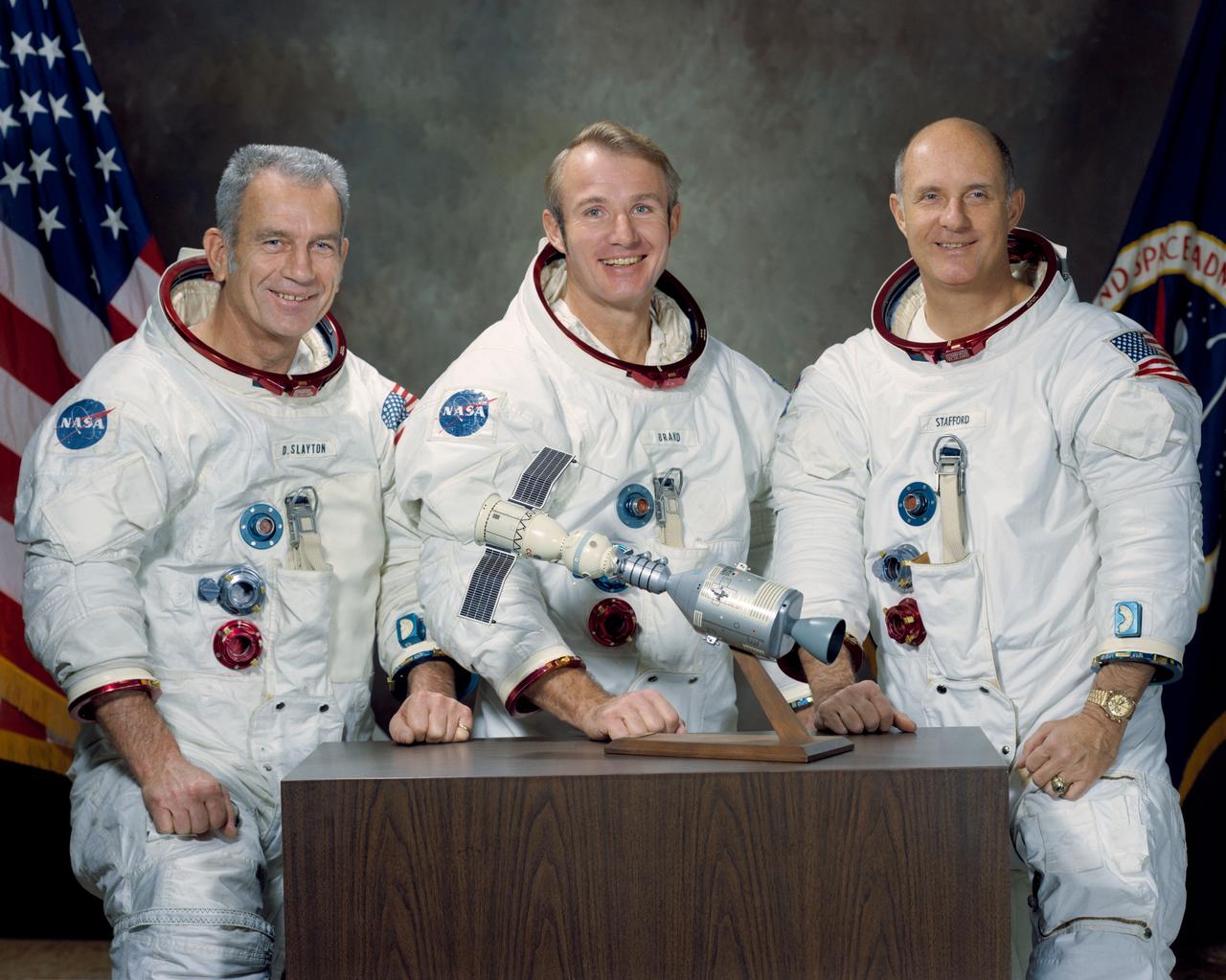
S74-15241 (January 1974) --- These three NASA astronauts are the United States flight crew for the 1975 Apollo-Soyuz Test Project (ASTP) mission. The prime crew members for the joint United States - Soviet Union spaceflight are, left to right, Donald K. Slayton, docking module pilot; Vance D. Brand, command module pilot; and Thomas P. Stafford, commander. The American and Soviet crews will visit one another?s spacecraft while the Soyuz and Apollo are docked in Earth orbit for a maximum of two days. The ASTP mission is designed to test equipment and techniques that will establish international crew rescue capability in space, as well as permit future cooperative scientific missions.
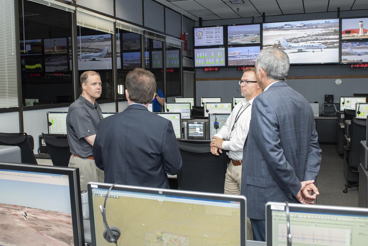
NASA Administrator Bridenstine learns about the many uses for mission control rooms for flight research projects such as monitoring the flights for safety, gathering data and talking to the pilot and project researcher.
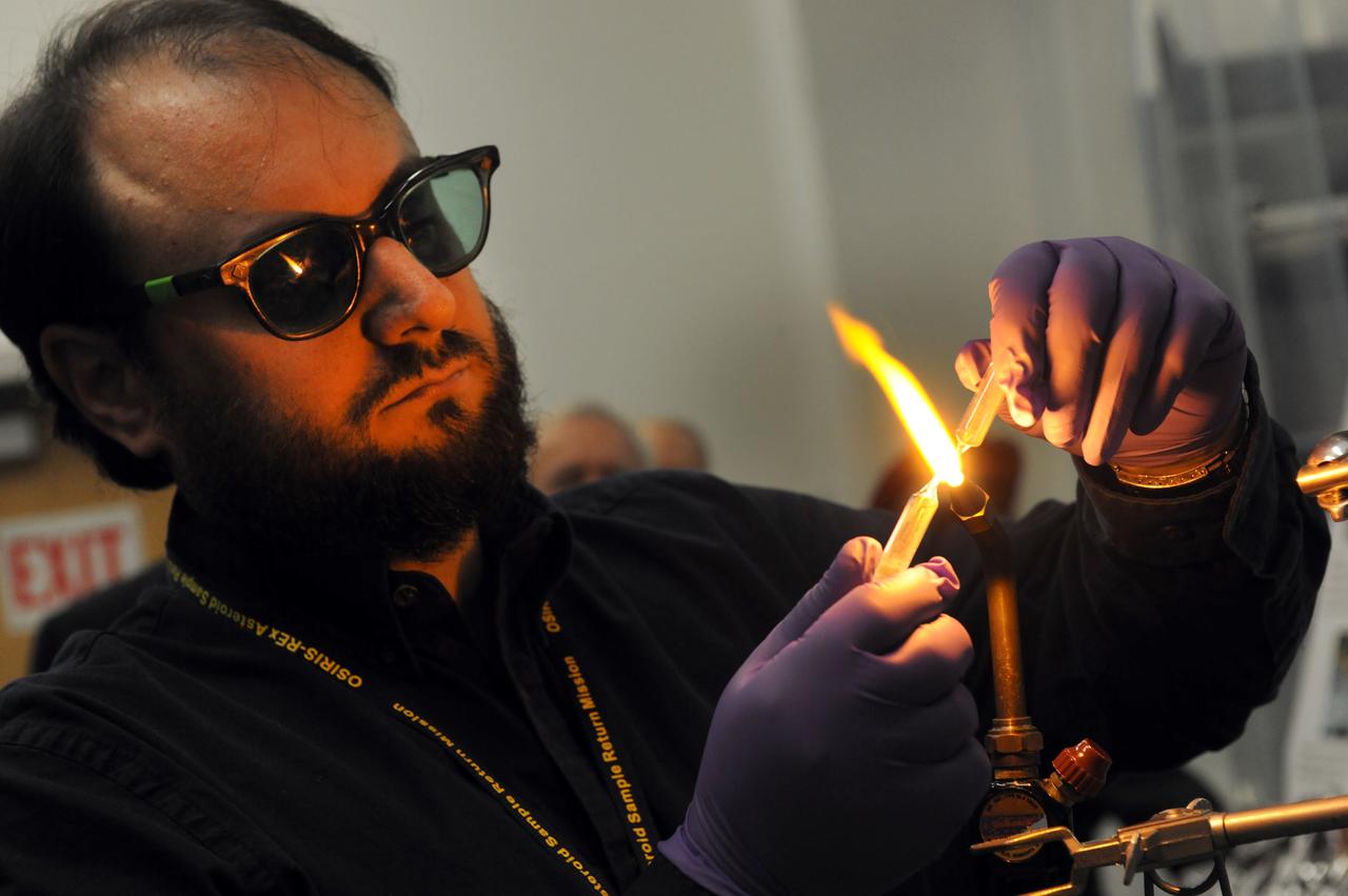
Dr. Jason Dworkin, Project Scientist for NASA's OSIRIS-Rex mission is seen hear sealing a glass test tube with a sample of Allende meteorite dust which is 4.567 BILLION years old. Jason is the Chief of NASA Goddard's Astrochemistry Lab. Read more about the mission here: <a href="http://www.nasa.gov/mission_pages/osiris-rex" rel="nofollow">www.nasa.gov/mission_pages/osiris-rex</a> Credit: NASA/Goddard/Debbie Mccallum <b><a href="http://www.nasa.gov/audience/formedia/features/MP_Photo_Guidelines.html" rel="nofollow">NASA image use policy.</a></b> <b><a href="http://www.nasa.gov/centers/goddard/home/index.html" rel="nofollow">NASA Goddard Space Flight Center</a></b> enables NASA’s mission through four scientific endeavors: Earth Science, Heliophysics, Solar System Exploration, and Astrophysics. Goddard plays a leading role in NASA’s accomplishments by contributing compelling scientific knowledge to advance the Agency’s mission. <b>Follow us on <a href="http://twitter.com/NASAGoddardPix" rel="nofollow">Twitter</a></b> <b>Like us on <a href="http://www.facebook.com/pages/Greenbelt-MD/NASA-Goddard/395013845897?ref=tsd" rel="nofollow">Facebook</a></b> <b>Find us on <a href="http://instagram.com/nasagoddard?vm=grid" rel="nofollow">Instagram</a></b>

Computer Engineer Gilena Monroe photographed for the NASA Hidden Figures project.
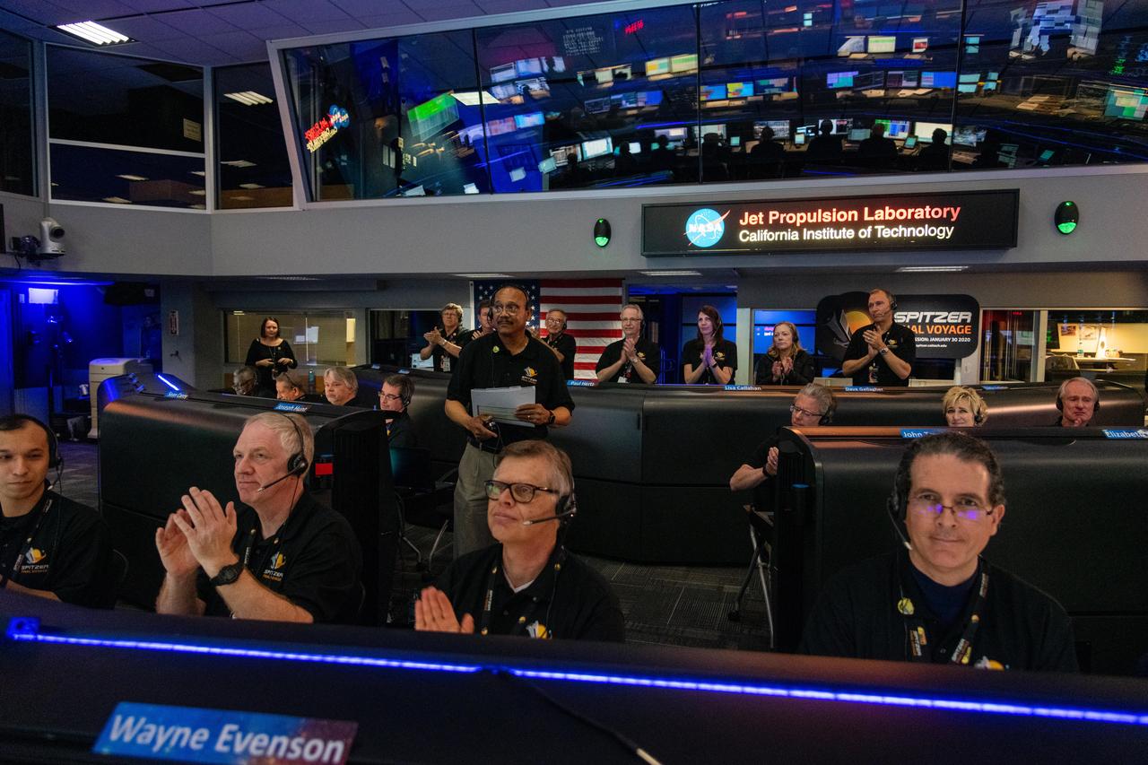
Spitzer Project Manager Joseph Hunt stands in Mission Control at NASA's Jet Propulsion Laboratory in Pasadena, California, on Jan. 30, 2020, declaring the spacecraft decommissioned and the Spitzer mission concluded. https://photojournal.jpl.nasa.gov/catalog/PIA23648
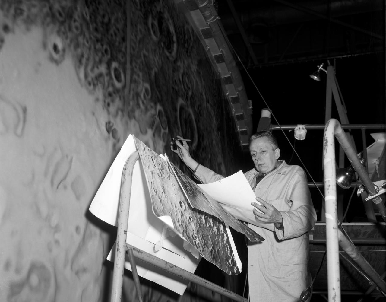
Artists used paintbrushes and airbrushes to recreate the lunar surface on each of the four models comprising the LOLA simulator. Project LOLA or Lunar Orbit and Landing Approach was a simulator built at Langley to study problems related to landing on the lunar surface. It was a complex project that cost nearly $2 million dollars. James Hansen wrote: "This simulator was designed to provide a pilot with a detailed visual encounter with the lunar surface; the machine consisted primarily of a cockpit, a closed-circuit TV system, and four large murals or scale models representing portions of the lunar surface as seen from various altitudes. The pilot in the cockpit moved along a track past these murals which would accustom him to the visual cues for controlling a spacecraft in the vicinity of the moon. Unfortunately, such a simulation--although great fun and quite aesthetic--was not helpful because flight in lunar orbit posed no special problems other than the rendezvous with the LEM, which the device did not simulate. Not long after the end of Apollo, the expensive machine was dismantled." (p. 379) Ellis J. White further described LOLA in his paper "Discussion of Three Typical Langley Research Center Simulation Programs," "Model 1 is a 20-foot-diameter sphere mounted on a rotating base and is scaled 1 in. = 9 miles. Models 2,3, and 4 are approximately 15x40 feet scaled sections of model 1. Model 4 is a scaled-up section of the Crater Alphonsus and the scale is 1 in. = 200 feet. All models are in full relief except the sphere." -- Published in James R. Hansen, Spaceflight Revolution, NASA SP-4308, p. 379; Ellis J. White, "Discussion of Three Typical Langley Research Center Simulation Programs," Paper presented at the Eastern Simulation Council (EAI's Princeton Computation Center), Princeton, NJ, October 20, 1966.
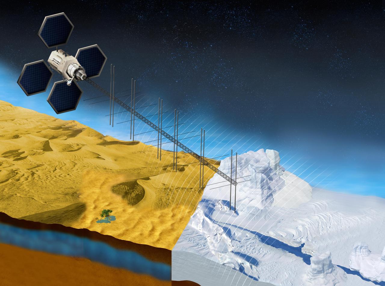
The OASIS project seeks to study fresh water aquifers in the desert as well as ice sheets in places like Greenland. This illustration shows what a satellite with a proposed radar instrument for the mission could look like. https://photojournal.jpl.nasa.gov/catalog/PIA23790
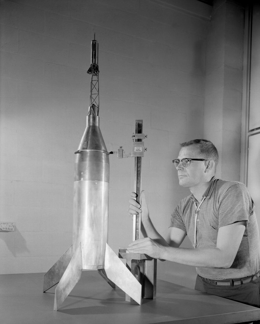
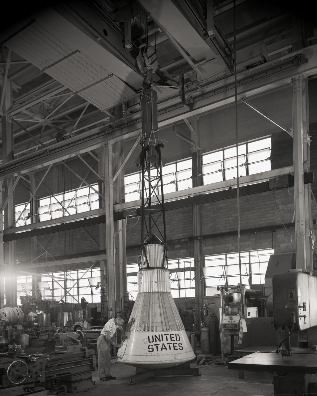
Publicity photograph of a technician measuring a wind tunnel model of the Little Joe test vehicle. Joseph Shortal noted that (vol. 3, p. 29): The largest project at Wallops in support of Mercury was the Little Joe project, designed to qualify the abort-escape system under flight conditions. James Hansen (p. 47) writes: STG engineers Max Faget and Paul Purser, then of Langley's PARD, had conceived Little Joe as a space capsule test vehicle even before the establishment of NASA and the formation of the STG. Girlruth understood the importance of the Little Joe tests: We had to be sure there were no serious performance and operational problems that we had simply not thought of in such a new and radical type of flight vehicle. -- Published in James R. Hansen, Spaceflight Revolution: NASA Langley Research Center From Sputnik to Apollo, (Washington: NASA, 1995), p. 47 Joseph A. Shortal, History of Wallops Station: Origins and Activities Through 1949, (Wallops Island, VA: National Aeronautics and Space Administration, Wallops Station, nd), Comment Edition.
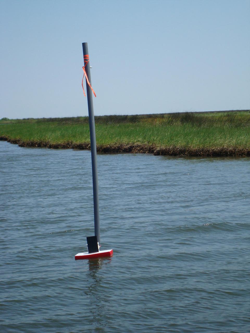
Once tethered in place in Gulf Coast waters, a DRIFTER sensor device is able to transmit valuable information about water temperature and conductivity. The Applied Science and Technology Project Office at Stennis Space Center designed the DRIFTER as an inexpensive device that can be used for science projects in local schools. Two of the devices, deployed in coastal waters, survived Hurricane Isaac, continuing to transmit valuable data regarding the storm.
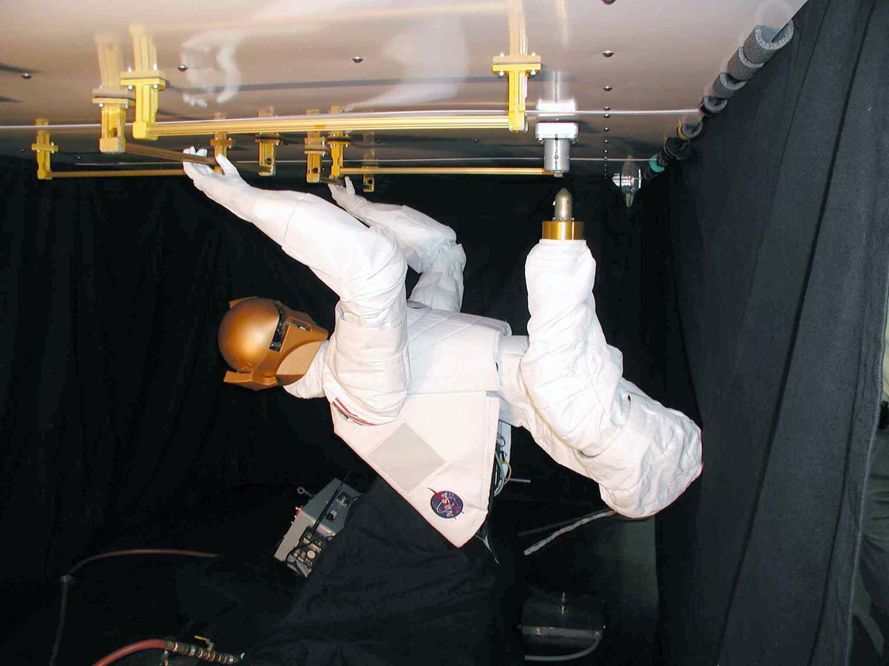
JSC2004-E-16343 (March 2004) --- Robonaut – which uses a head, torso, arms and dexterous hands to perform tasks using the same tools used by human spacewalkers – was fitted with a movable leg that ended in a “foot” that was a common interface for the standard Work Interface Facility (WIF) anchors on the International Space Station (ISS). The Robonaut Project is a collaborative effort with the Defense Advanced Research Projects Agency (DARPA), and has been under development at Johnson Space Center (JSC) for several years.
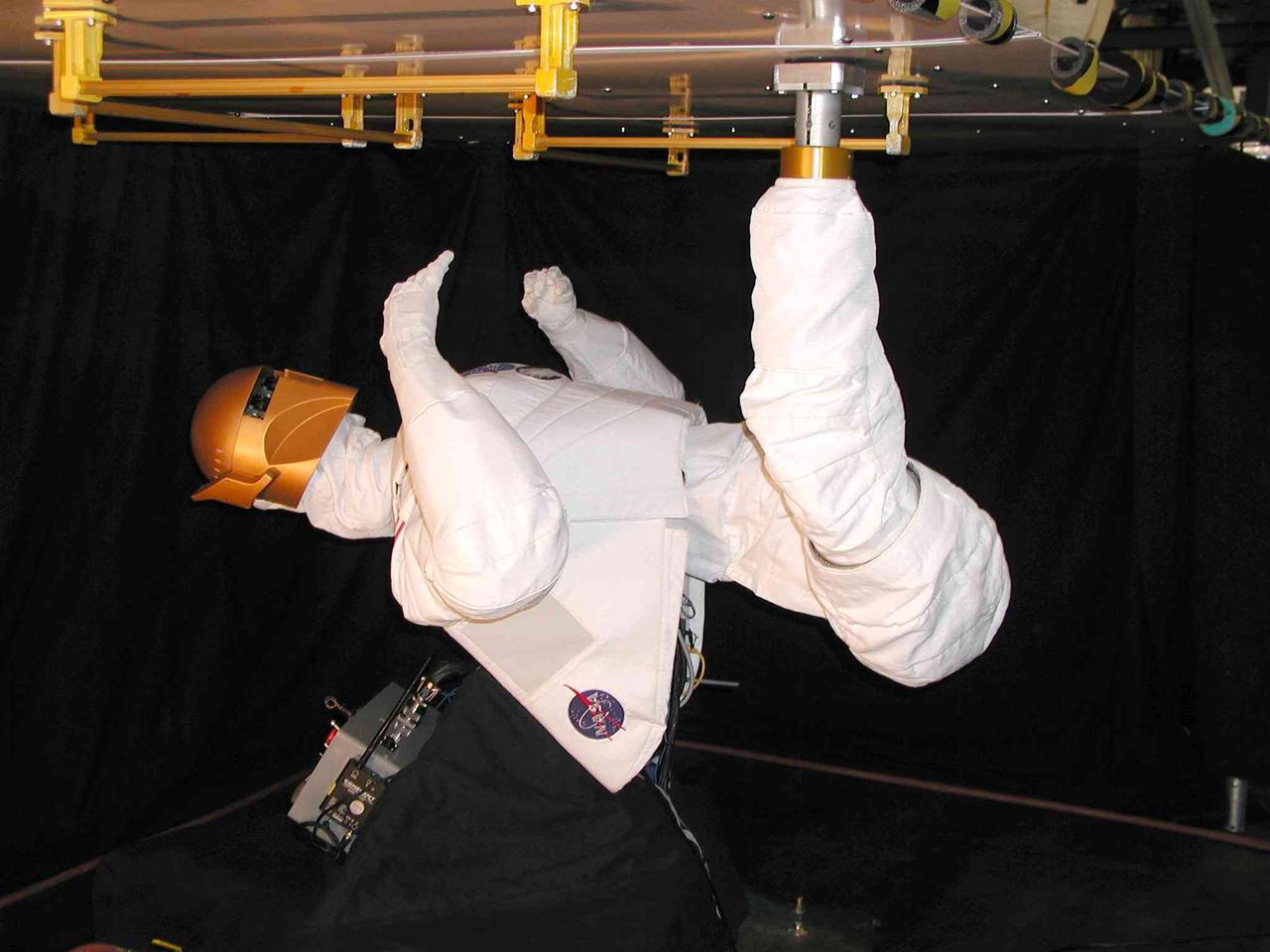
JSC2004-E-16339 (March 2004) --- Robonaut - which uses a head, torso, arms and dexterous hands to perform tasks using the same tools used by human spacewalkers – has both hands free once its leg is anchored in a standard Work Interface Facility (WIF) attached to the test panel. The Robonaut Project is a collaborative effort with the Defense Advanced Research Projects Agency (DARPA), and has been under development at Johnson Space Center (JSC) for several years.
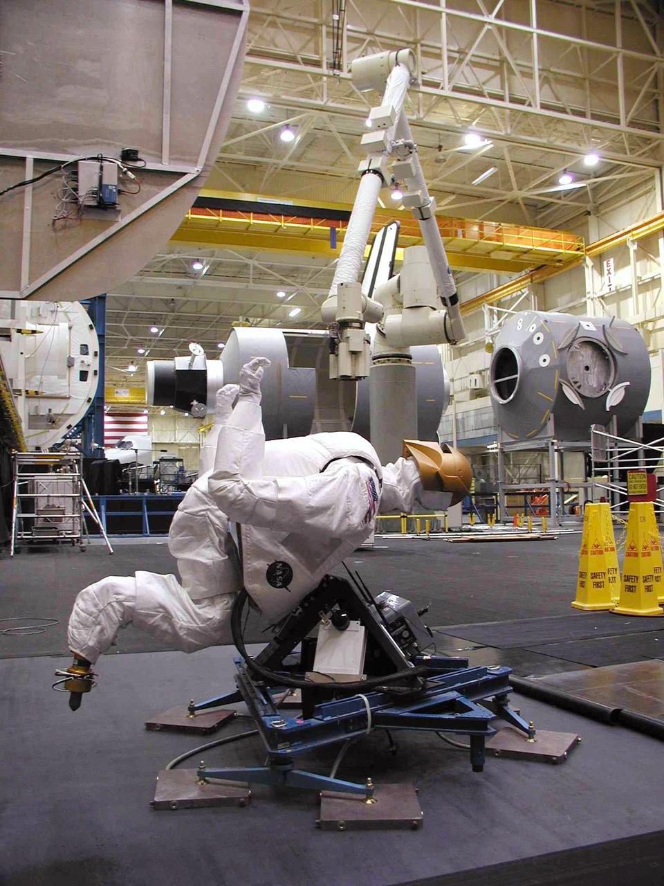
JSC2004-E-16342 (March 2004) --- Tests of Robonaut’s ability were conducted on the Precision Air-Bearing Floor in Johnson Space Center’s (JSC) Space Vehicle Mockup Facility. Robonaut was mounted to a pressurized air sled, which allowed teleoperators to emulate some of the conditions of weightlessness. The Robonaut Project is a collaborative effort with the Defense Advanced Research Projects Agency (DARPA), and has been under development at JSC for several years.
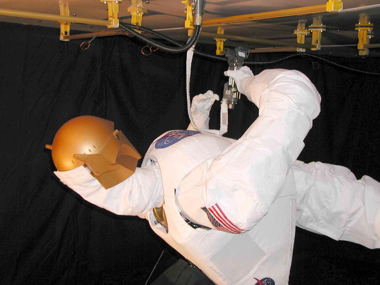
JSC2004-E-16341 (March 2004) --- Robonaut uses a standard human spacewalk tether to connect itself to an International Space Station (ISS) exterior handrail on the test panel. The Robonaut Project is a collaborative effort with the Defense Advanced Research Projects Agency (DARPA), and has been under development at Johnson Space Center (JSC) for several years.

Dr. Scott Shipley of Ascentech Enterprises makes an adjustment to the Spectrum unit. He is the project engineer for the effort working under the Engineering Services Contract at NASA's Kennedy Space Center. The device is being built for use aboard the International Space Station and is designed to expose different organisms to different color of fluorescent light while a camera records what's happening with time-laps imagery. Results from the Spectrum project will shed light on which living things are best suited for long-duration flights into deep space.
Example color image of lettuce plants growing in a plant chamber during preflight testing as part of Project Rapunzel. The image is captured using the same camera and lighting configuration as the spaceflight investigation. Project Rapunzel tests a special plant chamber and uses computer vision to monitor plant health. Investigation findings may inform ways to automatically monitor plant health and reduce plant stress during long-duration space missions. Credit. UniSQ
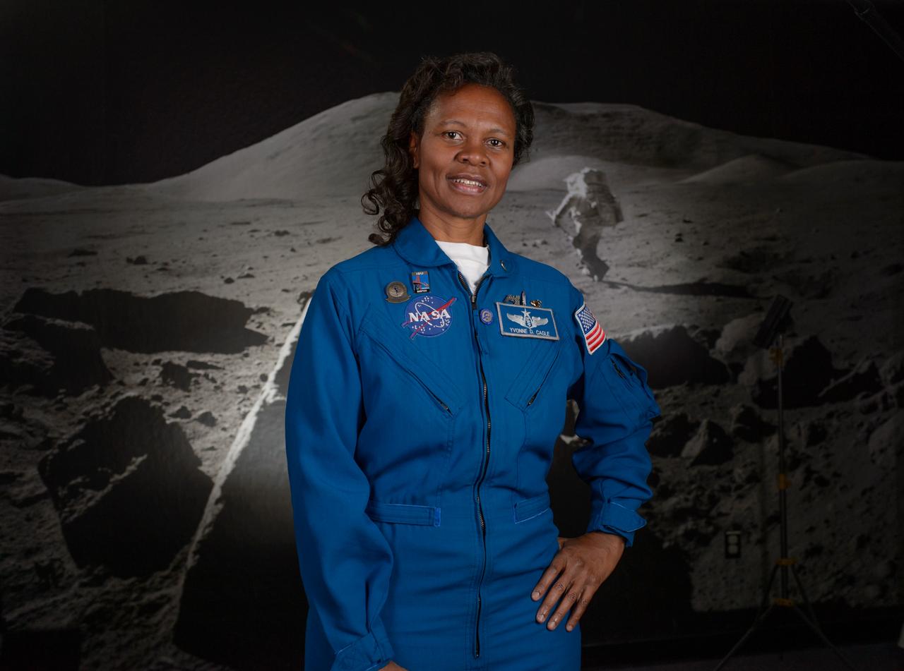
Astronaut Yvonne Cagle in the Apollo Moon Room of the Ames Exploration Center (943-A). Still photo for the NASA Hidden Figures Project.

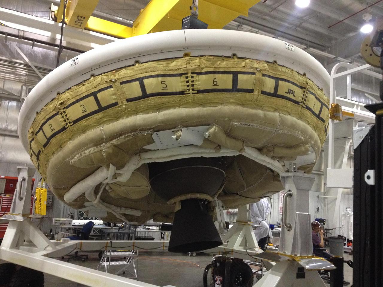
The main structural body of the second flight test vehicle in NASA Low-Density Supersonic Decelerator LDSD project is seen during its assembly in a cleanroom at NASA Jet Propulsion Laboratory.
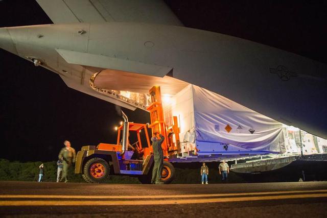
The saucer-shaped test vehicle for NASA Low-Density Supersonic Decelerator LDSD project, packaged in the box shown here, was shipped via plane to the Navy Pacific Missile Range Facility in Kauai, Hawaii on April 17.
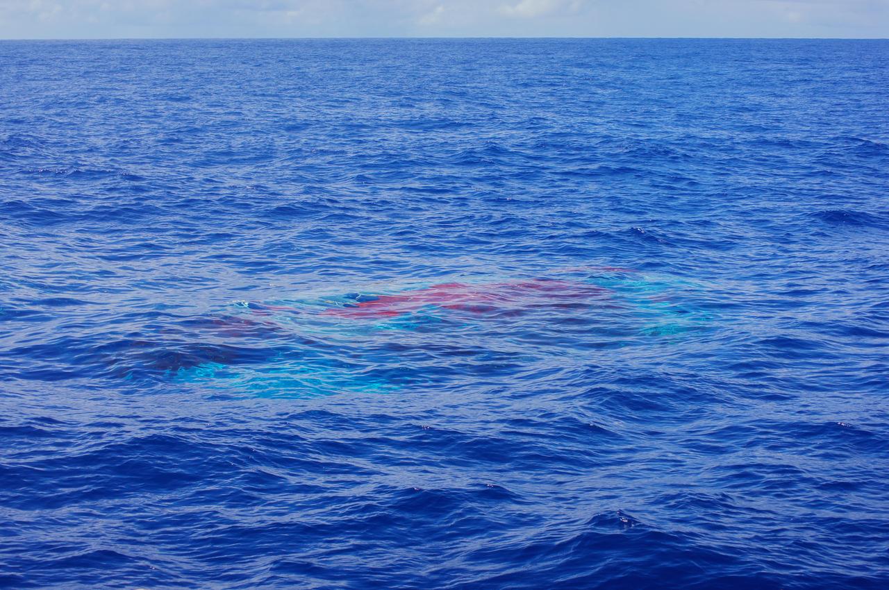
NASA Supersonic Disk Sail Parachute, one of the new technologies being developed as part of NASA Low-Density Supersonic Decelerator LDSD project, floats just below the surface of the Pacific Ocean on June 28, 2014.
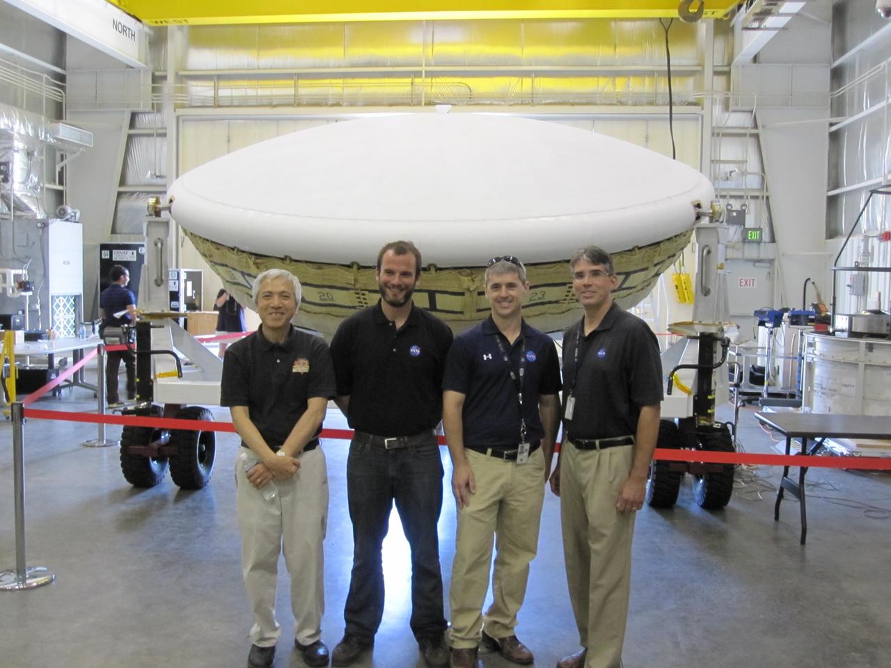
Members of the team for NASA Low-Density Supersonic Decelerator LDSD stand in front of the project saucer-shaped test vehicle at the U.S. Navy Pacific Missile Range Facility in Kauai, Hawaii.
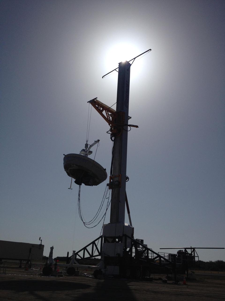
A saucer-shaped vehicle part of NASA Low-Density Supersonic Decelerator LDSD project designed to test interplanetary landing devices hangs on a tower in preparation for launch at the Pacific Missile Range Facility in Kauai, Hawaii.
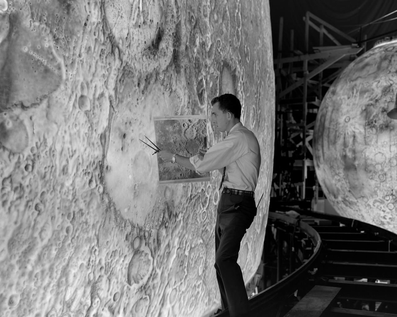
Artists used paintbrushes and airbrushes to recreate the lunar surface on each of the four models comprising the LOLA simulator. Project LOLA or Lunar Orbit and Landing Approach was a simulator built at Langley to study problems related to landing on the lunar surface. It was a complex project that cost nearly 2 million dollars. James Hansen wrote: This simulator was designed to provide a pilot with a detailed visual encounter with the lunar surface the machine consisted primarily of a cockpit, a closed-circuit TV system, and four large murals or scale models representing portions of the lunar surface as seen from various altitudes. The pilot in the cockpit moved along a track past these murals which would accustom him to the visual cues for controlling a spacecraft in the vicinity of the moon. Unfortunately, such a simulation--although great fun and quite aesthetic--was not helpful because flight in lunar orbit posed no special problems other than the rendezvous with the LEM, which the device did not simulate. Not long after the end of Apollo, the expensive machine was dismantled. (p. 379) Ellis J. White described the simulator as follows: Model 1 is a 20-foot-diameter sphere mounted on a rotating base and is scaled 1 in. 9 miles. Models 2,3, and 4 are approximately 15x40 feet scaled sections of model 1. Model 4 is a scaled-up section of the Crater Alphonsus and the scale is 1 in. 200 feet. All models are in full relief except the sphere. -- Published in James R. Hansen, Spaceflight Revolution: NASA Langley Research Center From Sputnik to Apollo, (Washington: NASA, 1995), p. 379 Ellis J. White, Discussion of Three Typical Langley Research Center Simulation Programs, Paper presented at the Eastern Simulation Council (EAI s Princeton Computation Center), Princeton, NJ, October 20, 1966.
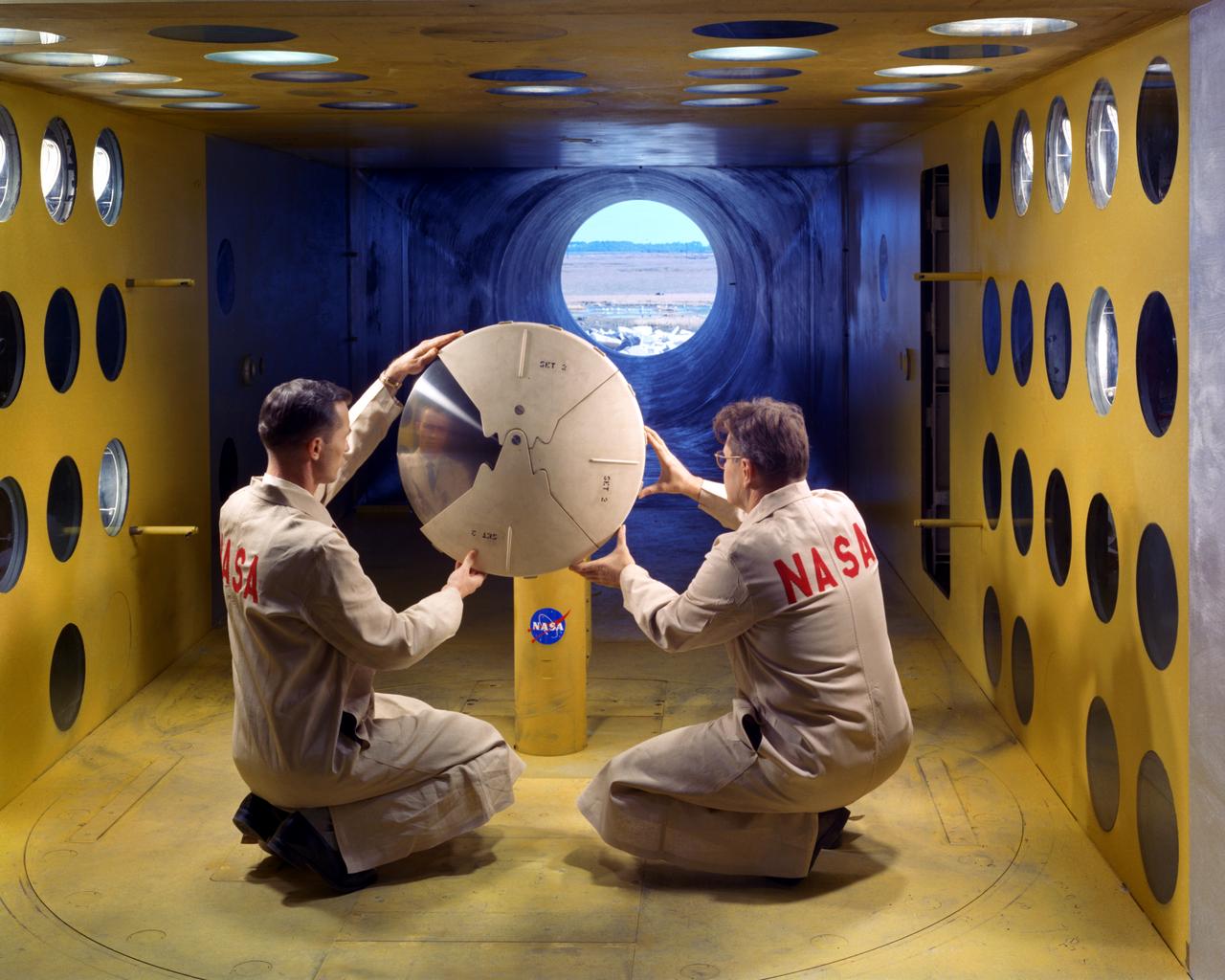
As part of the project FIRE study, technicians ready materials to be subjected to high temperatures that will simulate the effects of re-entry heating. Tests of various space capsule materials for Project FIRE were conducted. Photographed in the 9 X 6 Foot Thermal Structures Tunnel. Photograph published in Winds of Change, 75th Anniversary NASA publication, by James Schultz (page 78). Photograph also published in Engineer in Charge: A History of the Langley Aeronautical Laboratory, 1917-1958 by James R. Hansen (page 476). Also Published in the book " A Century at Langley" by Joseph Chambers. Pg. 92
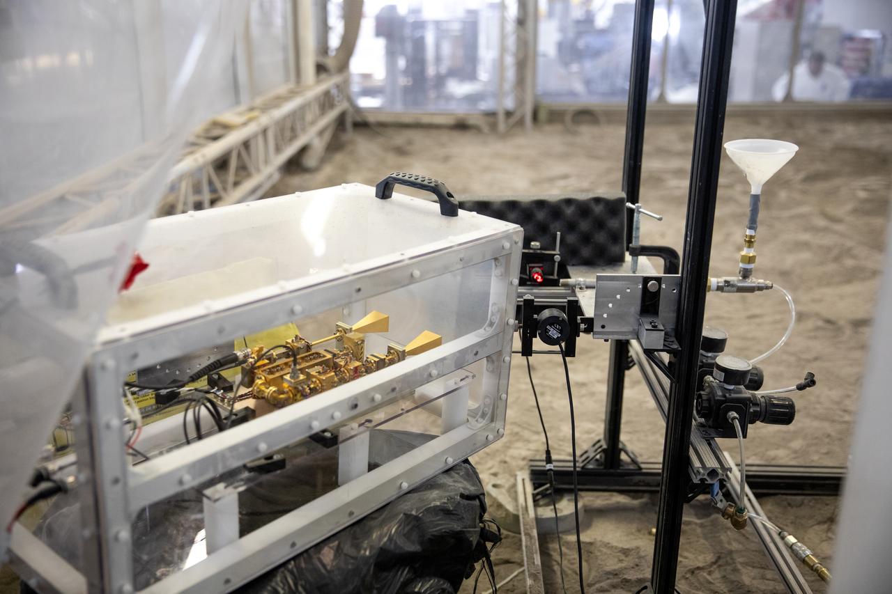
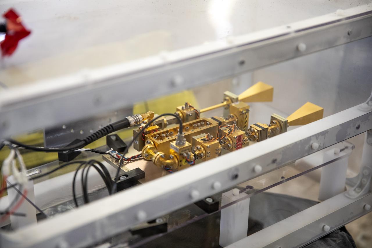
A team at NASA’s Kennedy Space Center in Florida assesses the Dust Concentration Monitor and the Millimeter Wave Doppler Radar inside a regolith bin at the Granular Mechanics and Regolith Operations (GMRO) lab at the spaceport’s Swamp Works on July 28, 2022, as part of Plume Surface Interaction (PSI) Instrumentation testing. The PSI Project is advancing both modeling and testing capabilities to understand exactly how rocket exhaust plumes affect a planetary landing site. This advanced modeling will help engineers evaluate the risks of various plumes on planetary surfaces, which will help them more accurately design landers for particular locations.
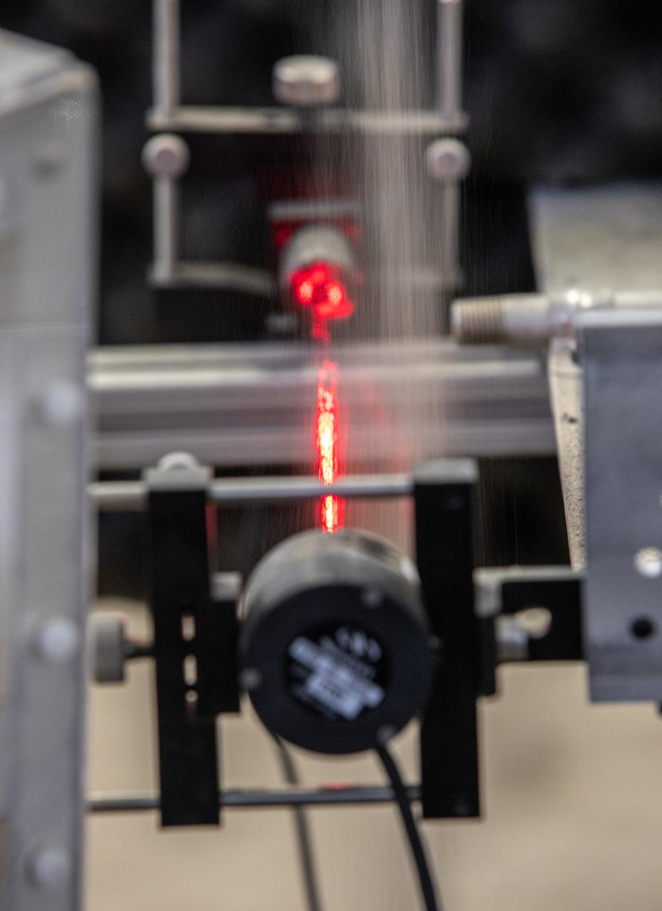
The Dust Concentration Monitor and the Millimeter Wave Doppler Radar undergo testing inside a regolith bin at the Granular Mechanics and Regolith Operations (GMRO) lab at the Kennedy Space Center’s Swamp Works on July 28, 2022, as part of Plume Surface Interaction (PSI) Instrumentation testing. The PSI Project is advancing both modeling and testing capabilities to understand exactly how rocket exhaust plumes affect a planetary landing site. This advanced modeling will help engineers evaluate the risks of various plumes on planetary surfaces, which will help them more accurately design landers for particular locations.
A team at NASA’s Kennedy Space Center in Florida assesses the Dust Concentration Monitor and the Millimeter Wave Doppler Radar inside a regolith bin at the Granular Mechanics and Regolith Operations (GMRO) lab at the spaceport’s Swamp Works on July 28, 2022, as part of Plume Surface Interaction (PSI) Instrumentation testing. The PSI Project is advancing both modeling and testing capabilities to understand exactly how rocket exhaust plumes affect a planetary landing site. This advanced modeling will help engineers evaluate the risks of various plumes on planetary surfaces, which will help them more accurately design landers for particular locations.
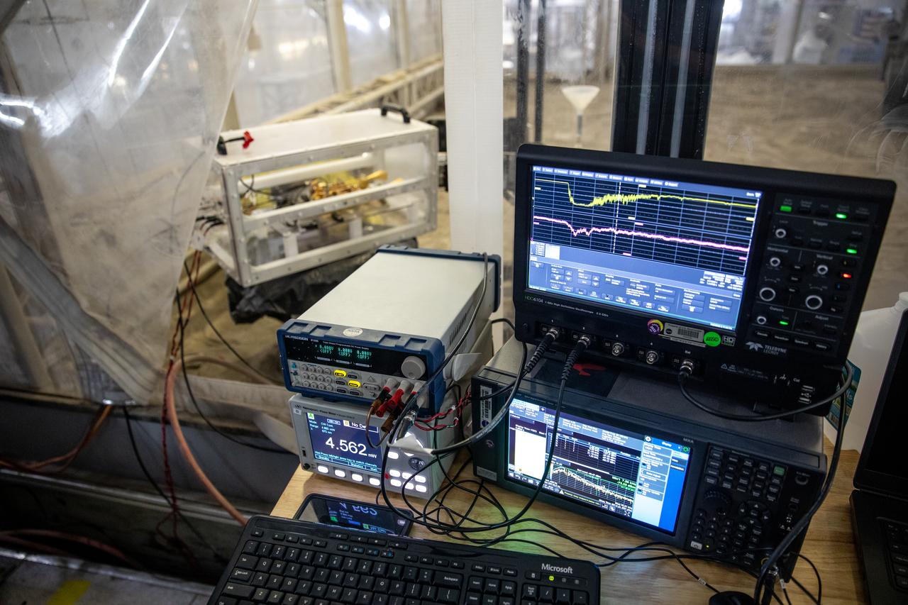
The Dust Concentration Monitor and the Millimeter Wave Doppler Radar undergo testing inside a regolith bin at the Granular Mechanics and Regolith Operations (GMRO) lab at the Kennedy Space Center’s Swamp Works on July 28, 2022, as part of Plume Surface Interaction (PSI) Instrumentation testing. The PSI Project is advancing both modeling and testing capabilities to understand exactly how rocket exhaust plumes affect a planetary landing site. This advanced modeling will help engineers evaluate the risks of various plumes on planetary surfaces, which will help them more accurately design landers for particular locations.
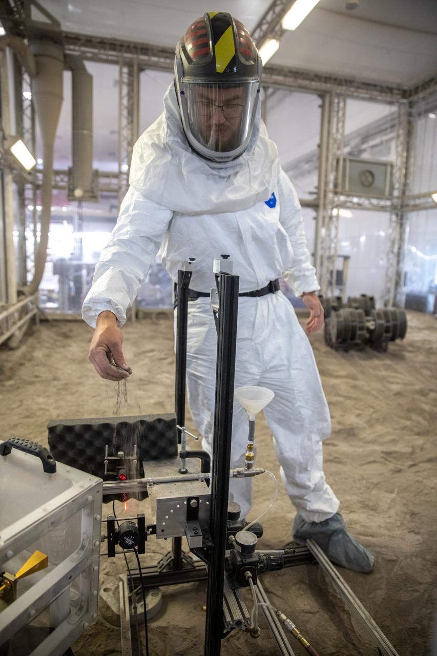
A team at NASA’s Kennedy Space Center in Florida assesses the Dust Concentration Monitor and the Millimeter Wave Doppler Radar inside a regolith bin at the Granular Mechanics and Regolith Operations (GMRO) lab at the spaceport’s Swamp Works on July 28, 2022, as part of Plume Surface Interaction (PSI) Instrumentation testing. The PSI Project is advancing both modeling and testing capabilities to understand exactly how rocket exhaust plumes affect a planetary landing site. This advanced modeling will help engineers evaluate the risks of various plumes on planetary surfaces, which will help them more accurately design landers for particular locations.
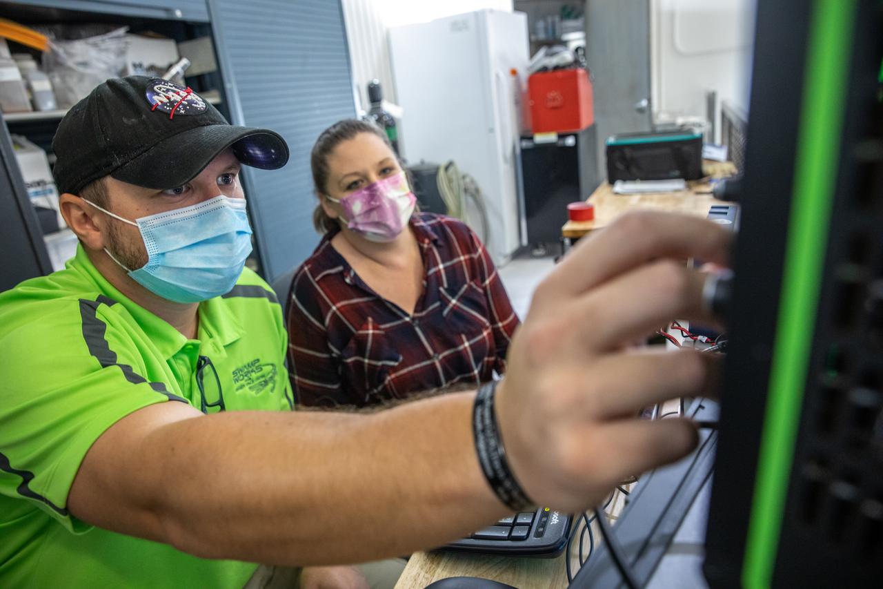
A team at NASA’s Kennedy Space Center in Florida assesses the Dust Concentration Monitor and the Millimeter Wave Doppler Radar inside a regolith bin at the Granular Mechanics and Regolith Operations (GMRO) lab at the spaceport’s Swamp Works on July 28, 2022, as part of Plume Surface Interaction (PSI) Instrumentation testing. The PSI Project is advancing both modeling and testing capabilities to understand exactly how rocket exhaust plumes affect a planetary landing site. This advanced modeling will help engineers evaluate the risks of various plumes on planetary surfaces, which will help them more accurately design landers for particular locations.
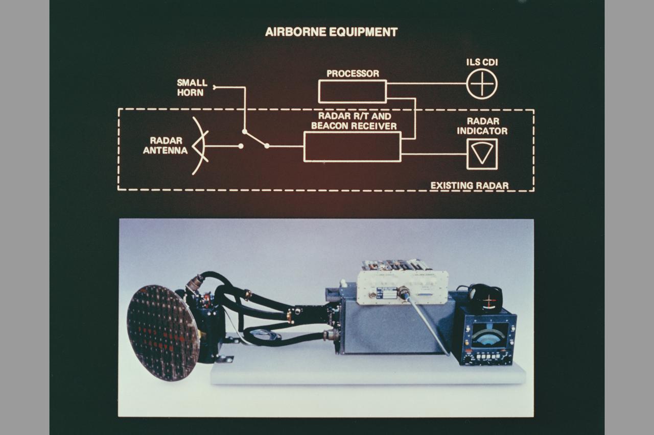
composite art Beacon Landing System Project (BL5): equipment
composite art Beacon Landing System Project (BL5). equipment
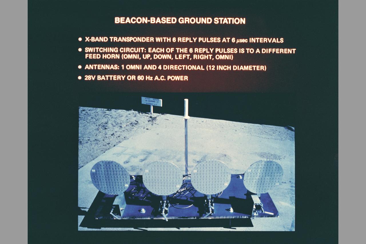
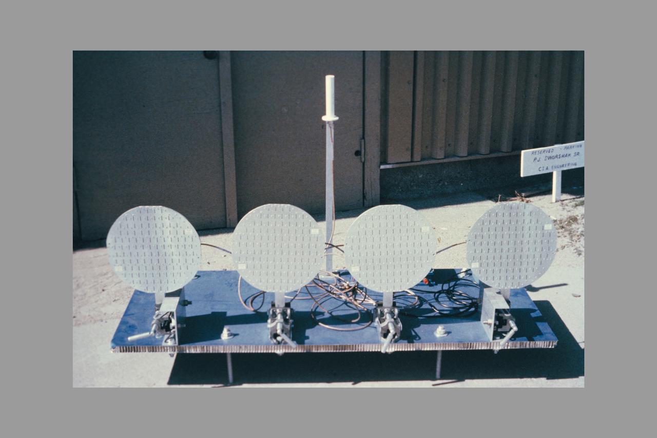
composite art Ground Station. Beacon Landing System Project (BL5).
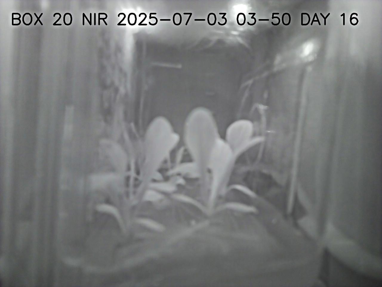
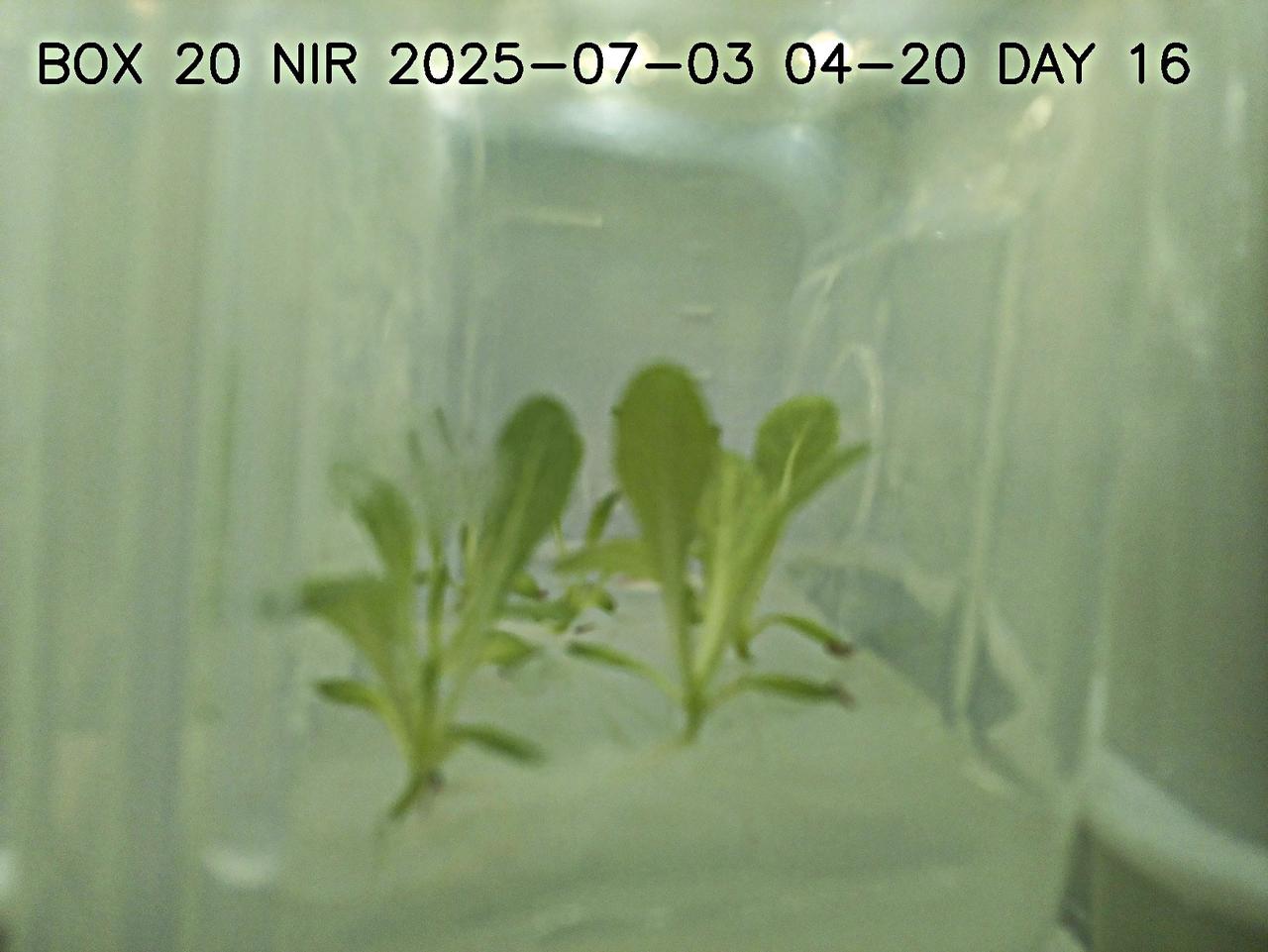
This image shows lettuce plants growing in a plant chamber during the preflight testing of Project Rapunzel. The image is captured using near infrared lights rather than white lights. Near infrared light allows plants to be observed during night hours without activating photosynthesis. Project Rapunzel aims to test a special plant chamber and uses computer vision to monitor plant health. Investigation findings may inform ways to automatically monitor plant health and reduce plant stress during long-duration space missions. Credit. UniSQ
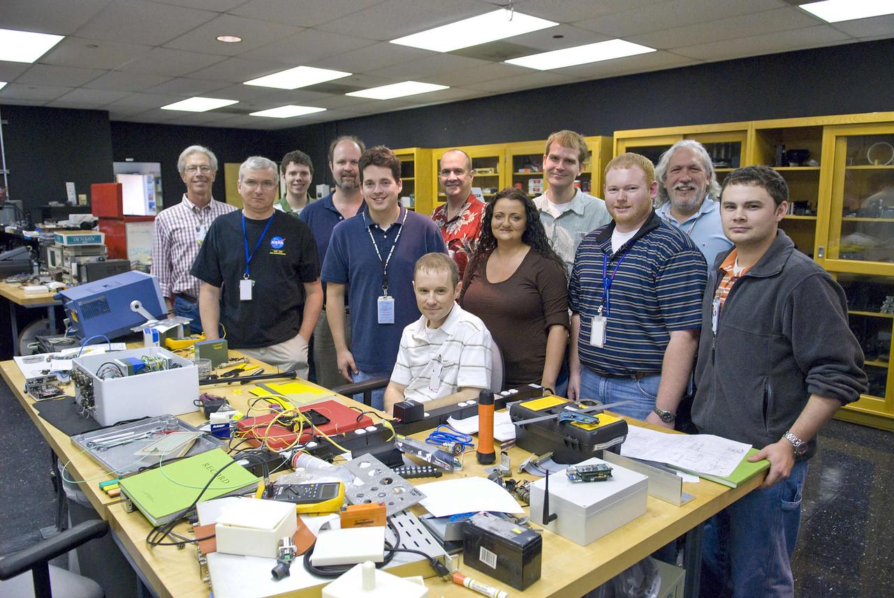
Engineers working on the smart and intelligent sensor payload project include (l to r): Ed Conley (NASA), Mark Mitchell (Jacobs Technology), Luke Richards (NASA), Robert Drackett (Jacobs Technology), Mark Turowski (Jacobs Technology) , Richard Franzl (seated, Jacobs Technology), Greg McVay (Jacobs Technology), Brianne Guillot (Jacobs Technology), Jon Morris (Jacobs Technology), Stephen Rawls (NASA), John Schmalzel (NASA) and Andrew Bracey (NASA).
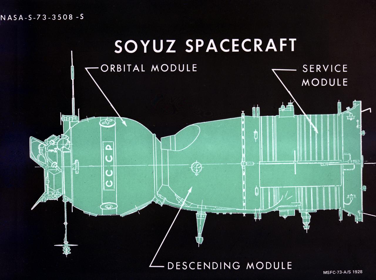
This illustration depicts a configuration of the Soyuz spacecraft for the Apollo-Soyuz Test Project (ASTP). The ASTP was the first international docking of the U.S.'s Apollo spacecraft and the U.S.S.R.'s Soyuz spacecraft in space. For this project, the Soviets built another in their continuing series of Soyuz space capsules. The U.S. used the Saturn IB Apollo capsule. A joint engineering team from the two countries met to develop a docking system that permitted the two spacecraft to link in space and allowed the crews to travel from one spacecraft to the other.
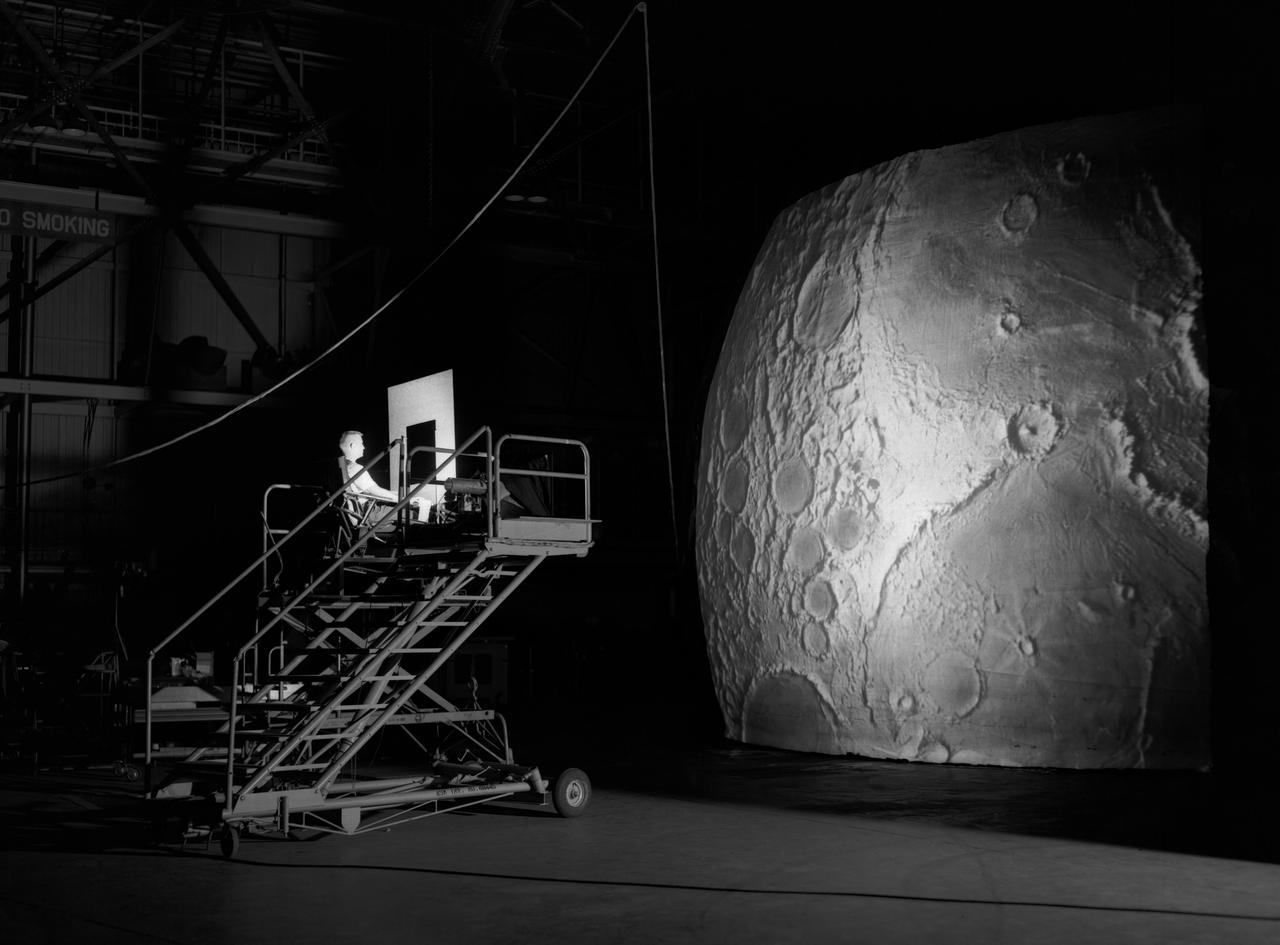
Test subject sitting at the controls: Project LOLA or Lunar Orbit and Landing Approach was a simulator built at Langley to study problems related to landing on the lunar surface. It was a complex project that cost nearly $2 million dollars. James Hansen wrote: "This simulator was designed to provide a pilot with a detailed visual encounter with the lunar surface; the machine consisted primarily of a cockpit, a closed-circuit TV system, and four large murals or scale models representing portions of the lunar surface as seen from various altitudes. The pilot in the cockpit moved along a track past these murals which would accustom him to the visual cues for controlling a spacecraft in the vicinity of the moon. Unfortunately, such a simulation--although great fun and quite aesthetic--was not helpful because flight in lunar orbit posed no special problems other than the rendezvous with the LEM, which the device did not simulate. Not long after the end of Apollo, the expensive machine was dismantled." (p. 379) Ellis J. White further described this simulator in his paper , "Discussion of Three Typical Langley Research Center Simulation Programs," (Paper presented at the Eastern Simulation Council (EAI's Princeton Computation Center), Princeton, NJ, October 20, 1966.) "A typical mission would start with the first cart positioned on model 1 for the translunar approach and orbit establishment. After starting the descent, the second cart is readied on model 2 and, at the proper time, when superposition occurs, the pilot's scene is switched from model 1 to model 2. then cart 1 is moved to and readied on model 3. The procedure continues until an altitude of 150 feet is obtained. The cabin of the LM vehicle has four windows which represent a 45 degree field of view. The projection screens in front of each window represent 65 degrees which allows limited head motion before the edges of the display can be seen. The lunar scene is presented to the pilot by rear projection on the screens with four Schmidt television projectors. The attitude orientation of the vehicle is represented by changing the lunar scene through the portholes determined by the scan pattern of four orthicons. The stars are front projected onto the upper three screens with a four-axis starfield generation (starball) mounted over the cabin and there is a separate starball for the low window." -- Published in James R. Hansen, Spaceflight Revolution: NASA Langley Research Center From Sputnik to Apollo, (Washington: NASA, 1995), p. 379.

jsc2021e063282 (12/10/2021) --- The logo of the Eco Pack project. The Packaging and Protecting Using Edible Products (Edible Foam) project tests a packaging foam using edible products. © CNES/GRARD Emmanuel, 2021