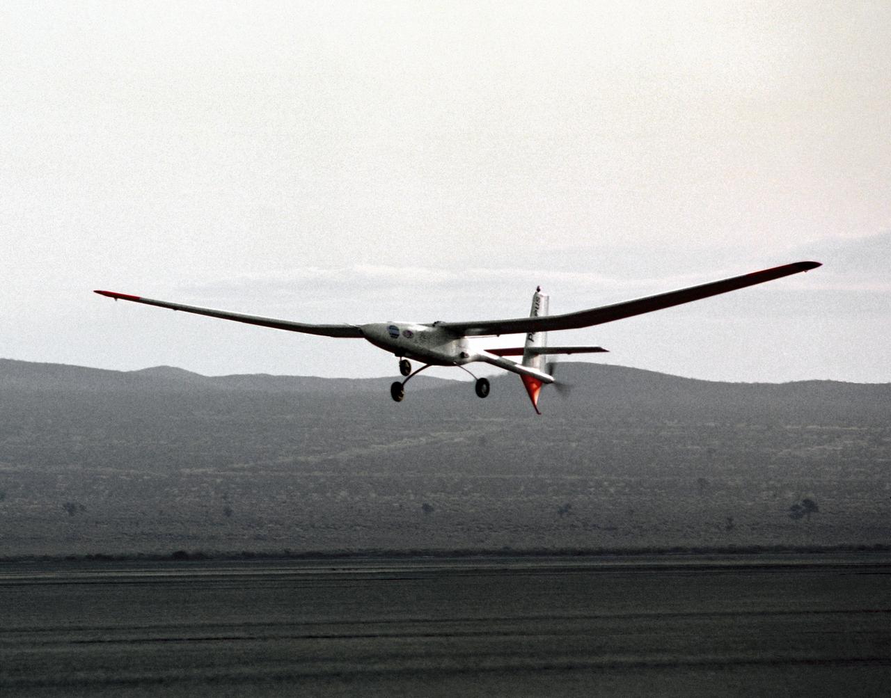
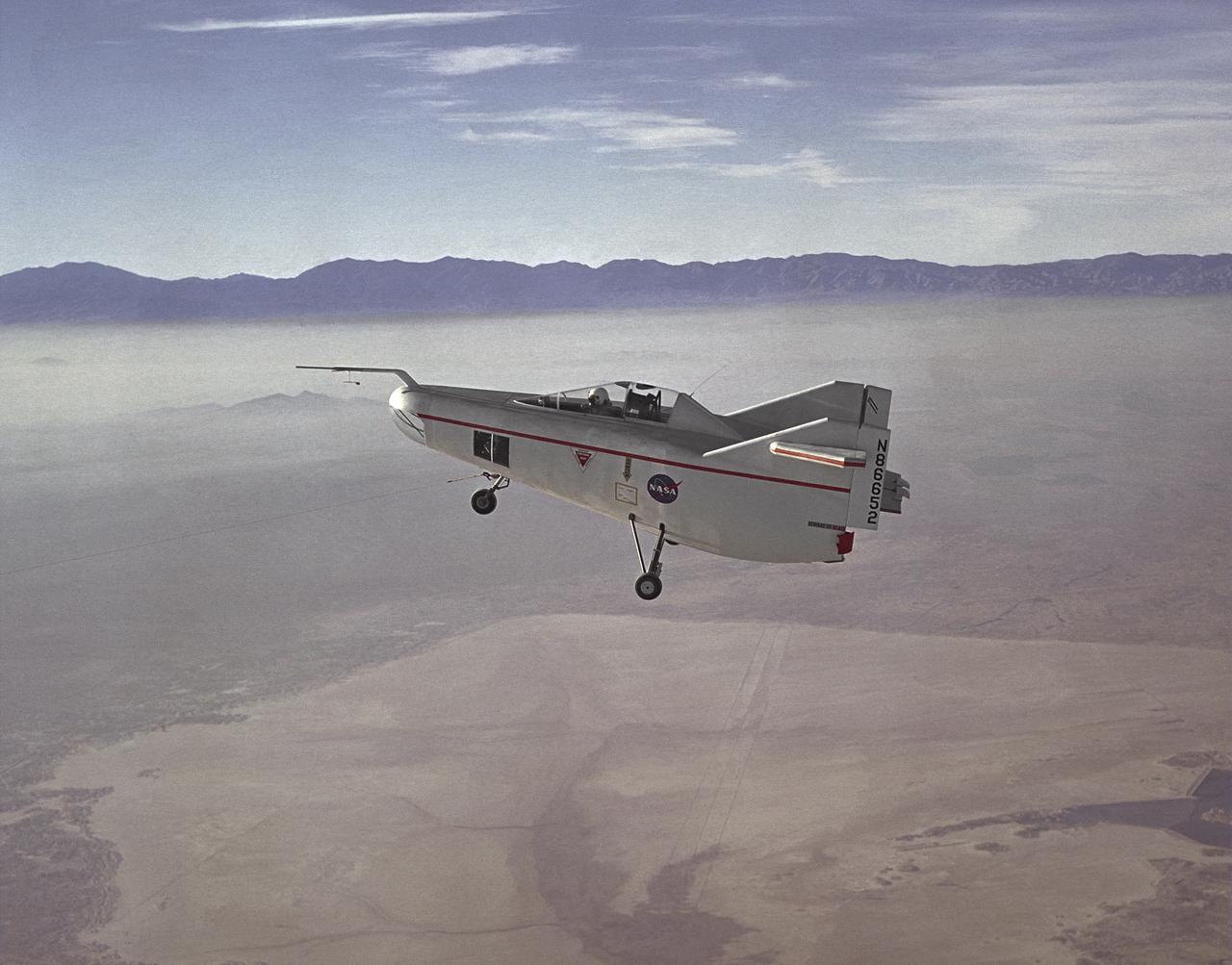
The Perseus proof-of-concept vehicle flies over Rogers Dry Lake at the Dryden Flight Research Center, Edwards, California, to test basic design concepts for the remotely-piloted, high-altitude vehicle.
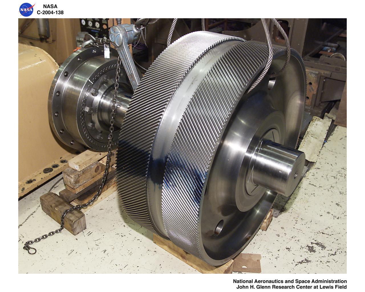
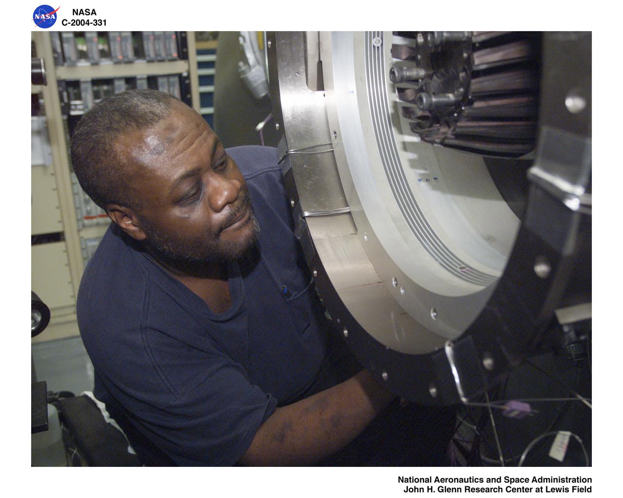
Ultra-Efficient Engine Technology Proof of Concept Compressor, Gearbox
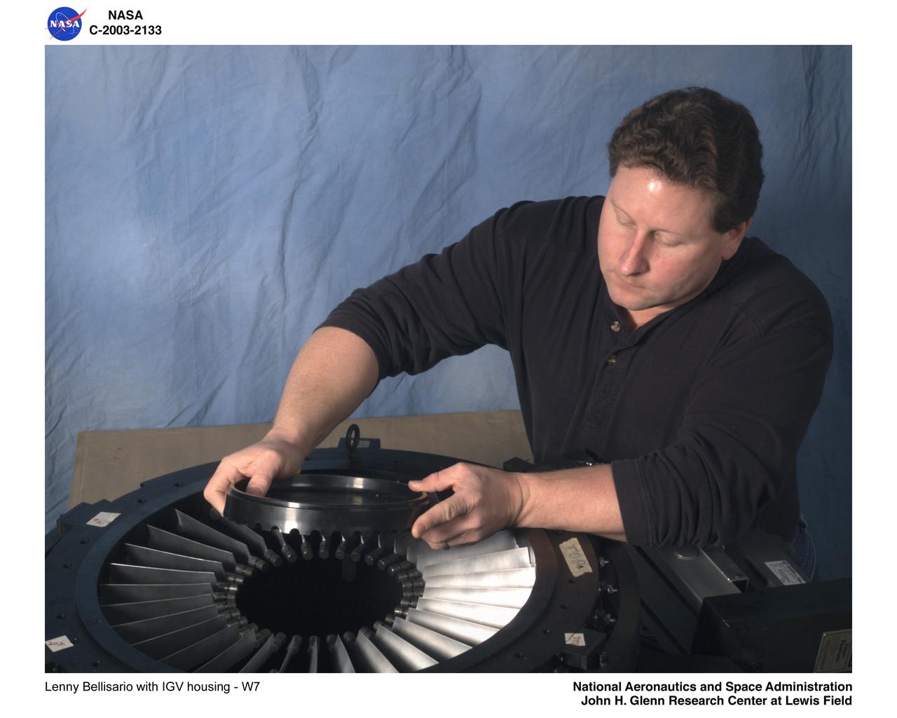
Ultra-Efficient Engine Technology (UEET) Proof of Concept Compressor (POCC)
Ultra-Efficient Engine Technology (UEET) Proof of Concept Compressor (POCC)
Ultra-Efficient Engine Technology - UEET - Proof of Concept Compressor - POCC - Advanced Compressor Casing Treatment Testing
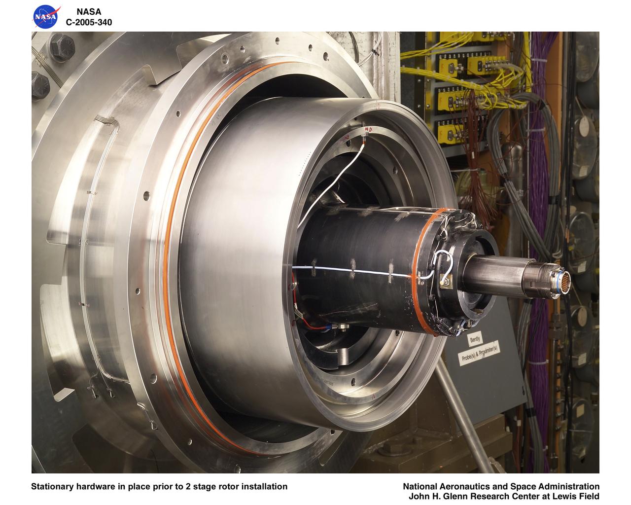
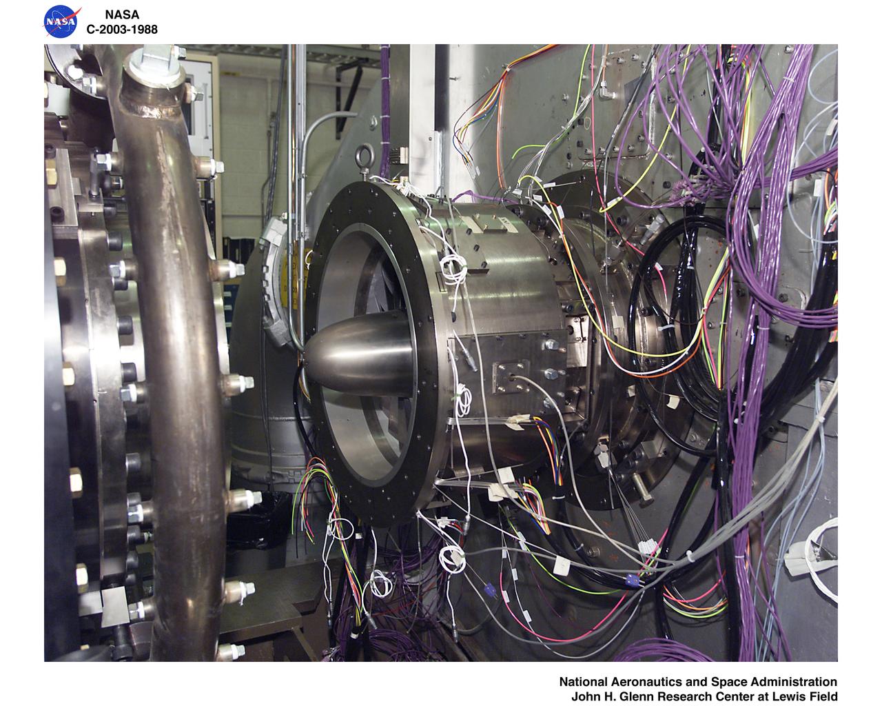
Ultra-Efficient Engine Technology (UEET) Proof of Concept Compressor, Stationary hardware in place prior to 2 stage rotor installation
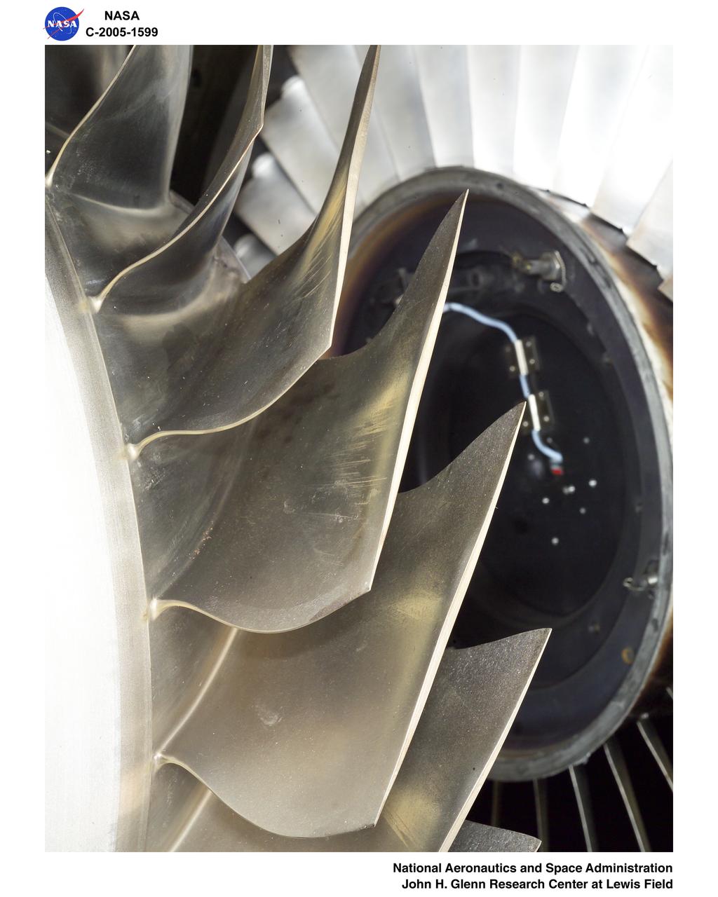
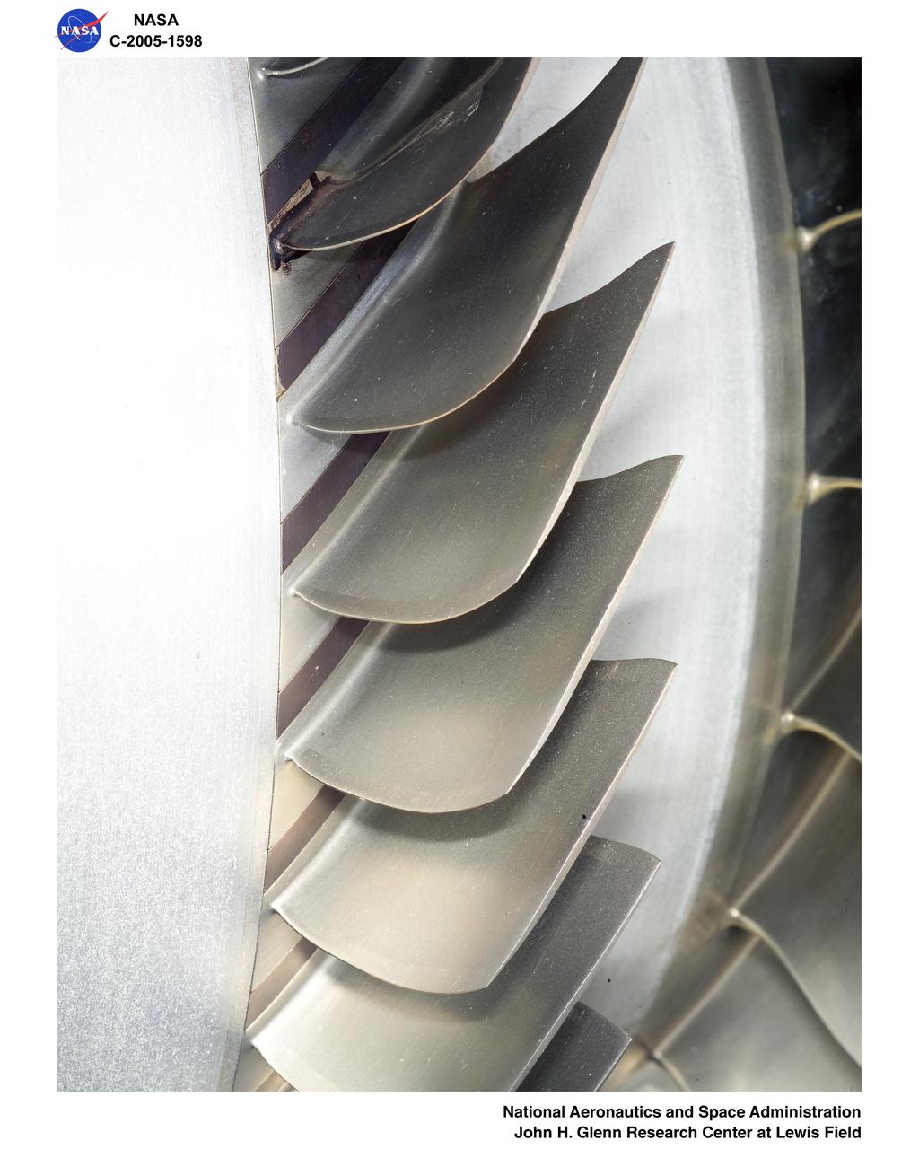
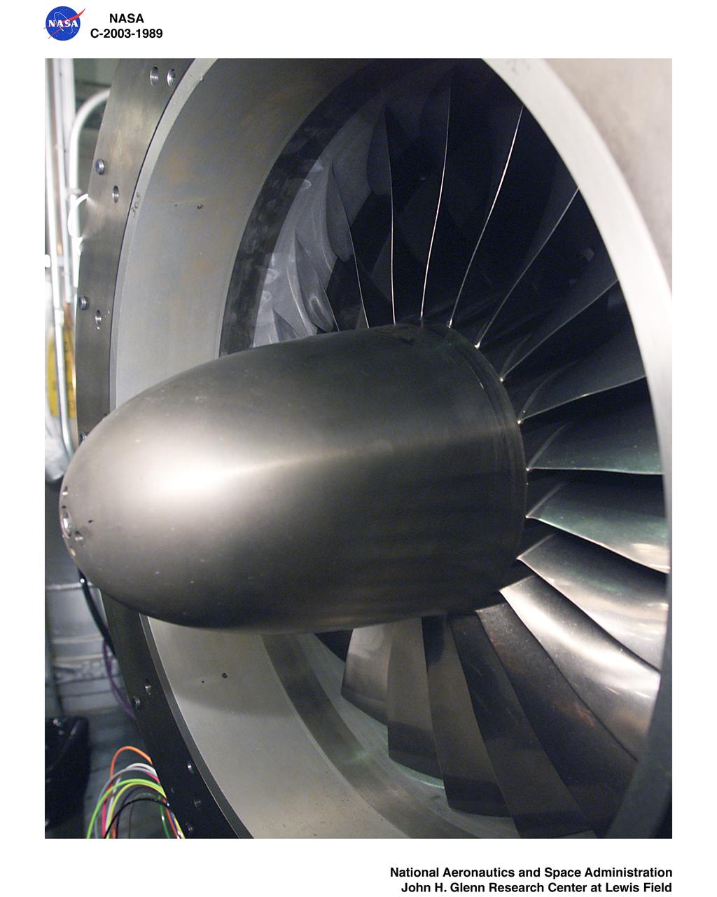
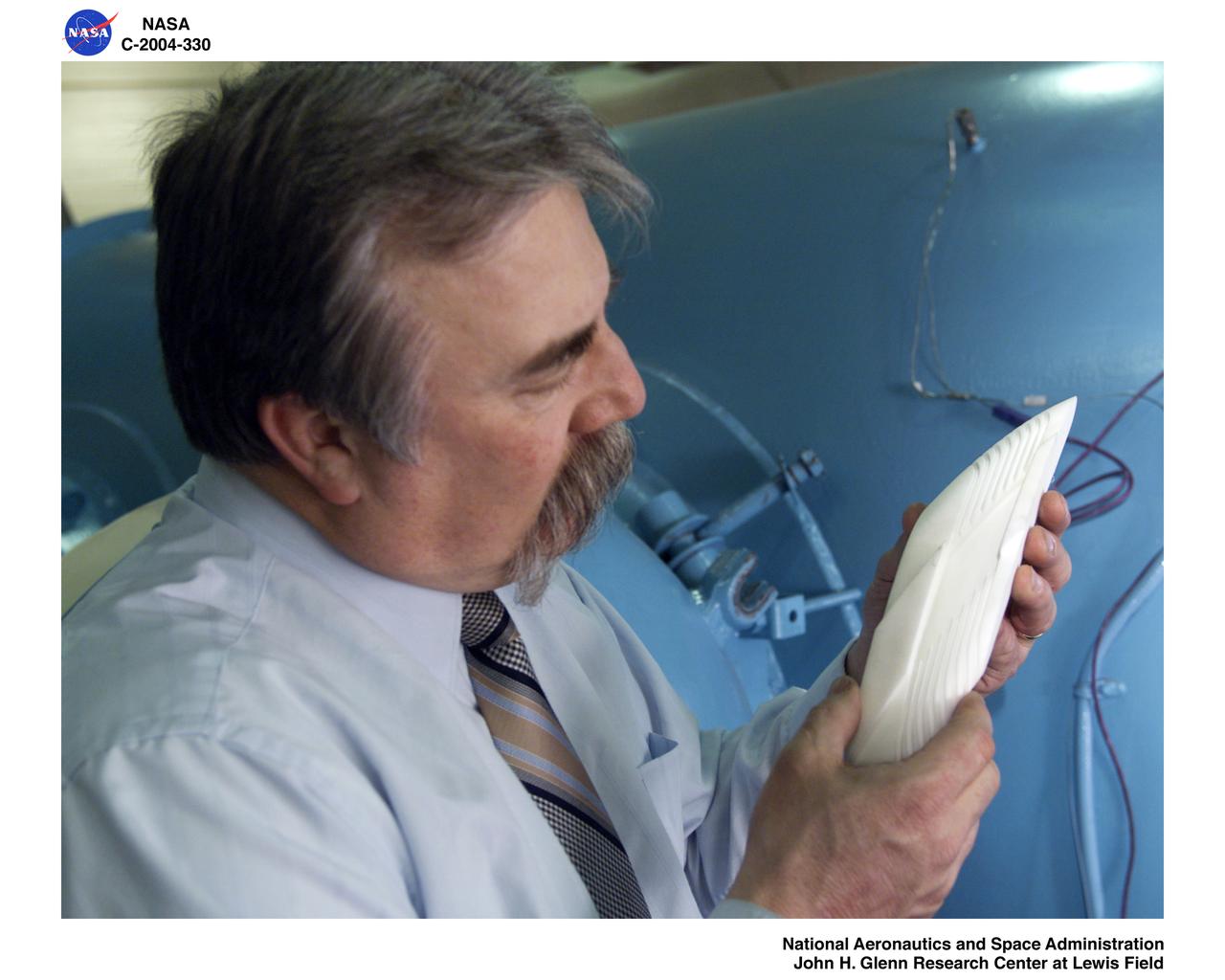
Ultra-Efficient Engine Technology - UEET - Proof of Concept Compressor, Two-stage Compressor
Ultra-Efficient Engine Technology - UEET - Proof of Concept Compressor, Two-stage Compressor
Ultra-Efficient Engine Technology - UEET - Proof of Concept Compressor, Two-stage Compressor
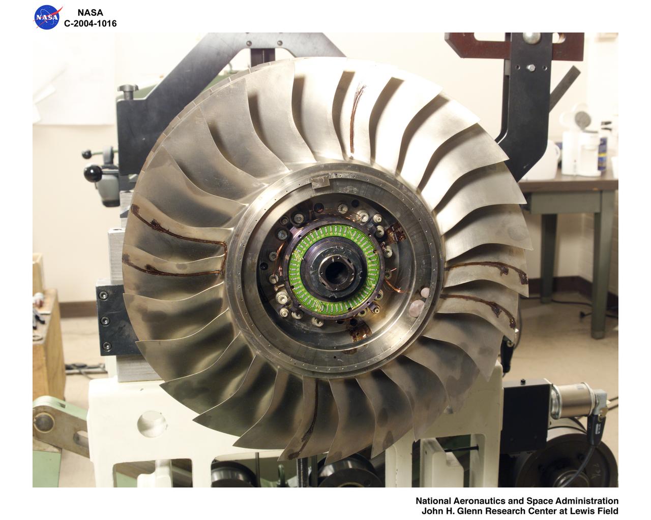
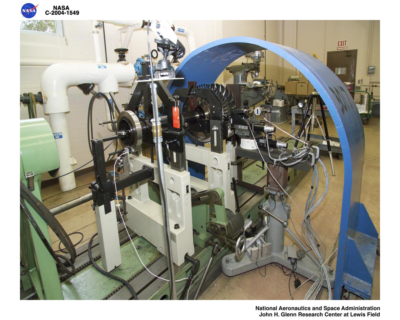
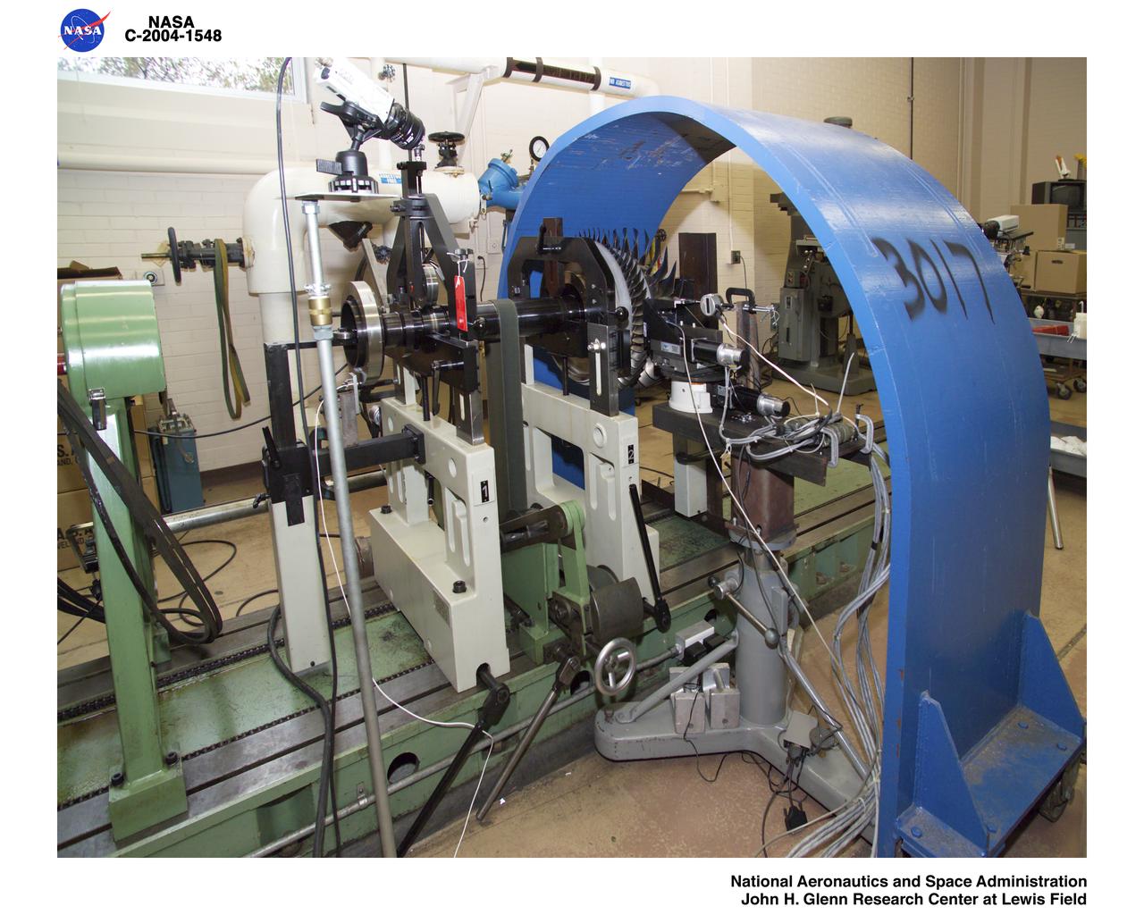
Ultra-Efficient Engine Technology (UEET), Proof of Concept Compressor, Shaft / Rotor Balance Assembly
Ultra-Efficient Engine Technology - UEET - Proof of Concept Compressor - POCC - Advanced Compressor Casing Treatment Testing
Ultra-Efficient Engine Technology - UEET - Proof of Concept Compressor - POCC - Advanced Compressor Casing Treatment Testing
Ultra-Efficient Engine Technology - UEET - Proof of Concept Compressor - POCC - Advanced Compressor Casing Treatment Testing
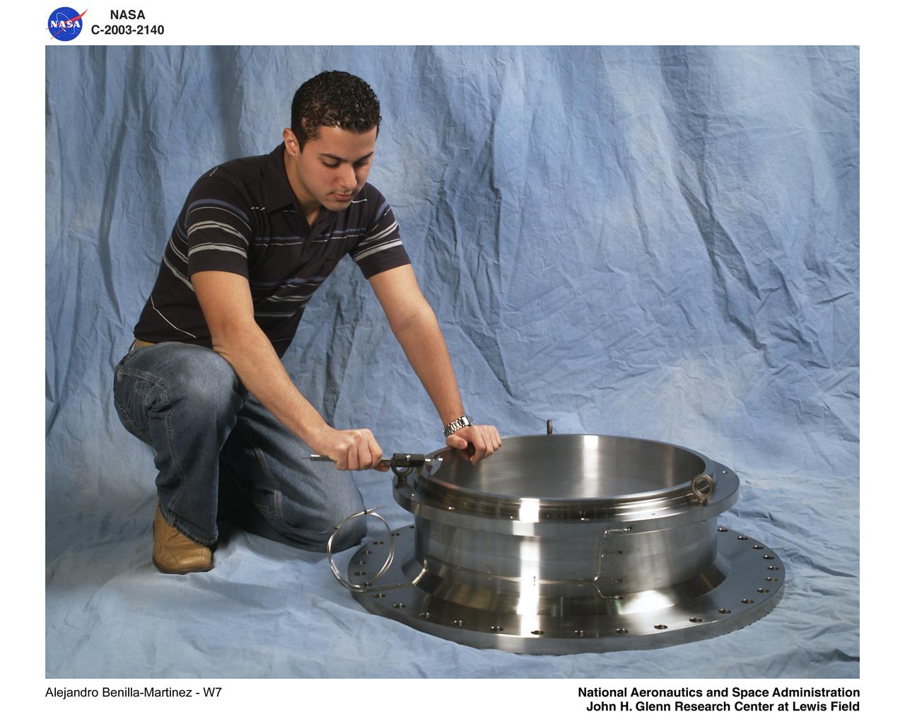
Ultra Efficient Engine Technology (UEET) W-7 2-Stage Proof of Concept Compressor - Blade Tip Clearance Sensor Calibration
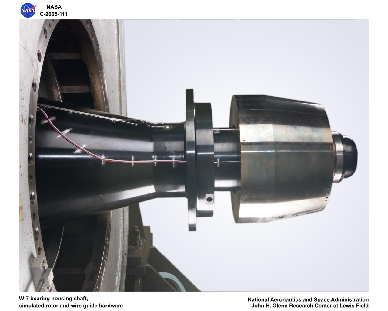
Ultra-Efficient Engine Technology (UEET), Proof of Concept Compressor, W-7 bearing housing shaft, simulated rotor wire guide hardware
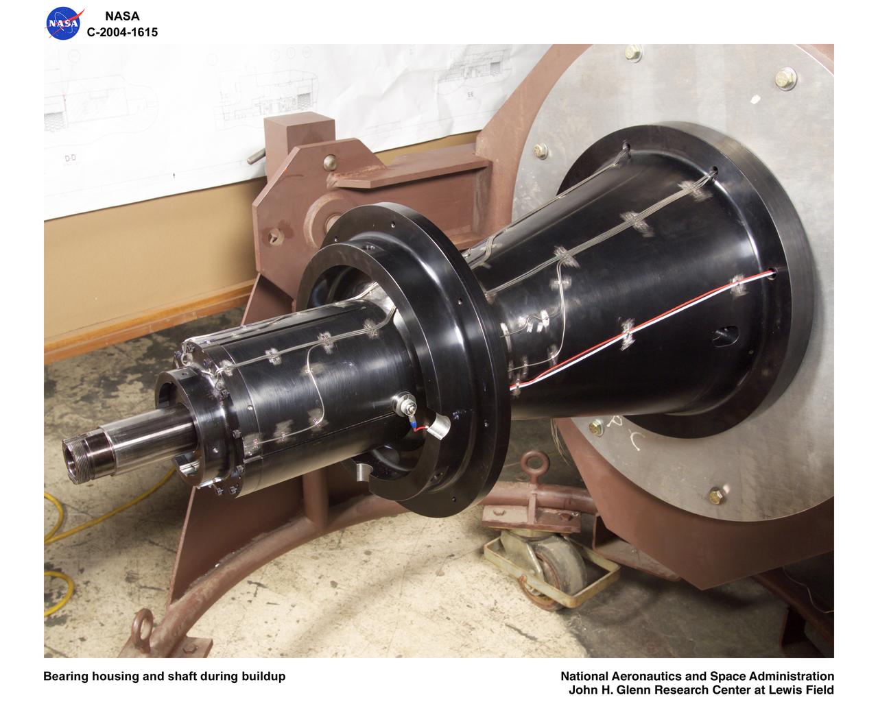
Ultra-Efficient Engine Technology (UEET), Proof of Concept Compressor, Advanced Compressor Casing Treatment testing; bearing housing and shaft during build-up
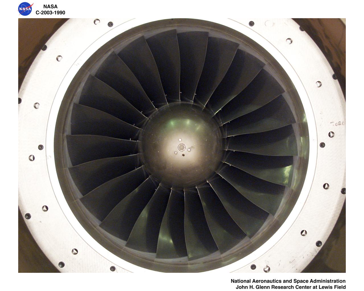
Ultra-Efficient Engine Technology (UEET) Proof of Concept Compressor, Advanced Compressor Casing Treatment testing, First Research Configuration (concentric grooves)
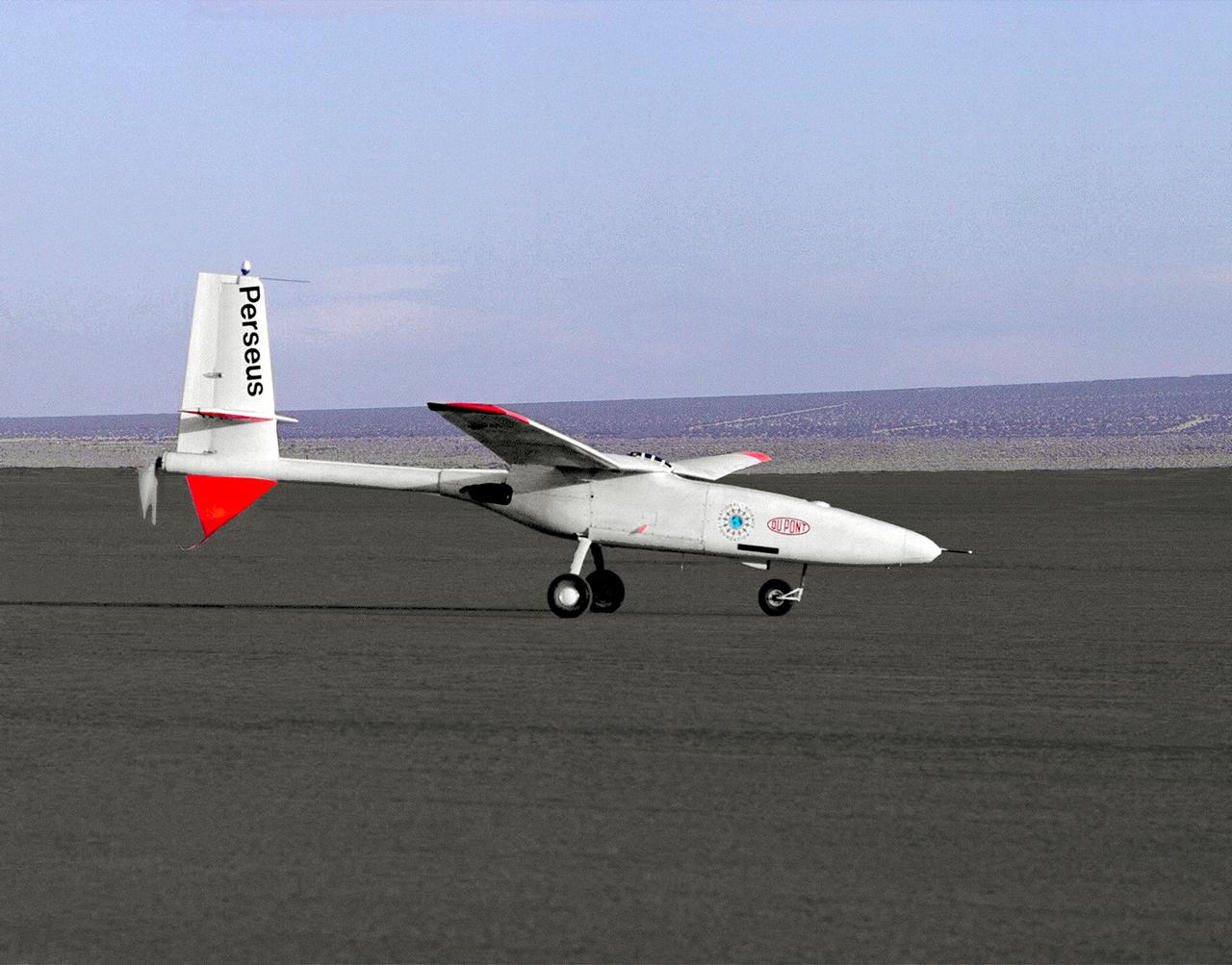
The Perseus proof-of-concept vehicle is seen here as it taxis on Rogers Dry Lake, adjacent the Dryden Flight Research Center, Edwards, California.
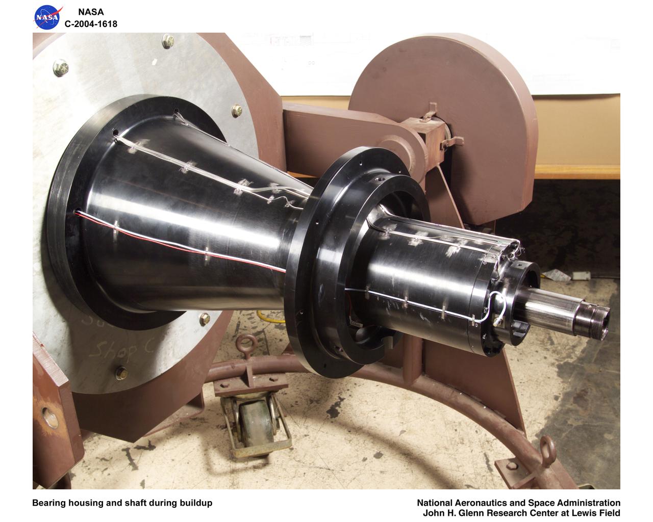
Ultra-Efficient Engine Technology (UEET), Proof of Concept Compressor, Advanced Compressor Casing Treatment testing; bearing housing and shaft during build-up
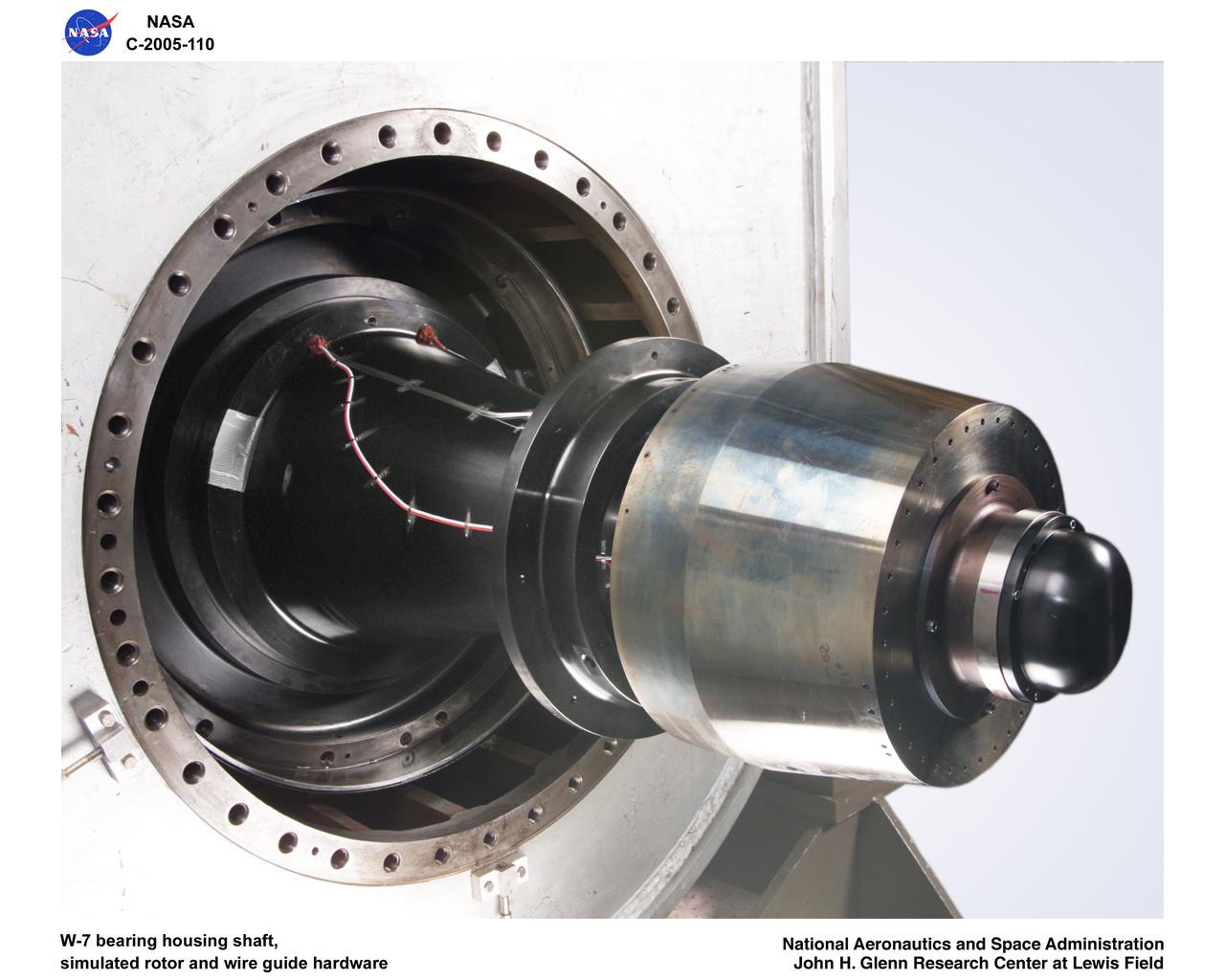
Ultra-Efficient Engine Technology (UEET), Proof of Concept Compressor, W-7 bearing housing shaft, simulated rotor wire guide hardware
Ultra-Efficient Engine Technology (UEET) Proof of Concept Compressor, Advanced Compressor Casing Treatment testing, First Research Configuration (concentric grooves)
Ultra Efficient Engine Technology (UEET) W-7 2-Stage Proof of Concept Compressor - Blade Tip Clearance Sensor Calibration
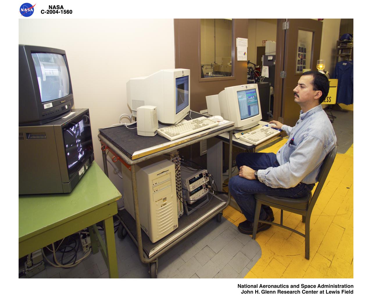
Ultra Efficient Engine Technology (UEET) W-7 2-Stage Proof of Concept Compressor - Blade Tip Clearance Sensor Calibration
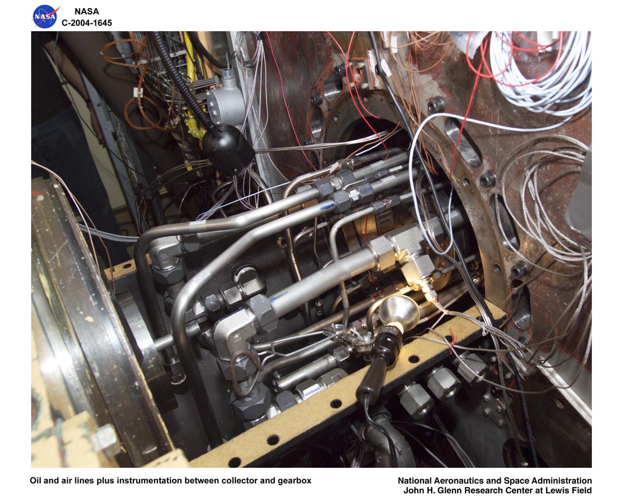
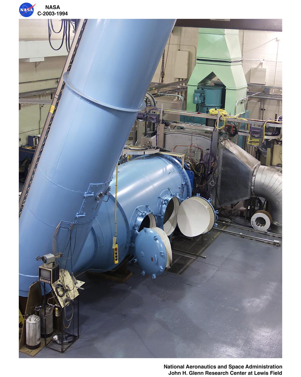
Ultra-Efficient Engine Technology (UEET), Proof of Concept Compressor, Advanced Compressor Casing Treatment testing; oil and air lines plus instrumentation between collector and gearbox
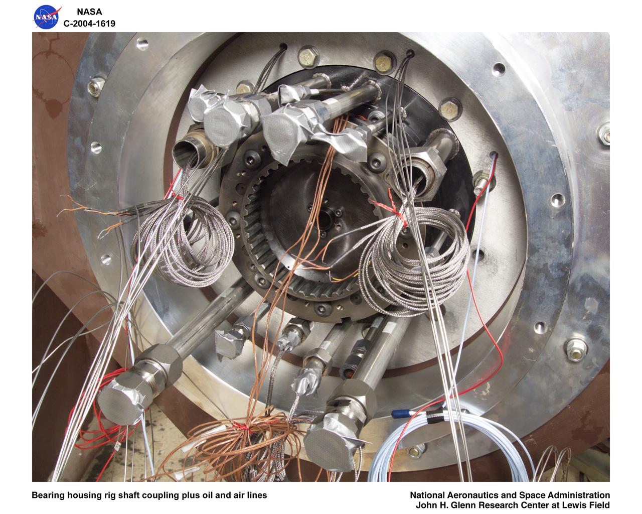
Ultra-Efficient Engine Technology (UEET), Proof of Concept Compressor, Advanced Compressor Casing Treatment testing; bearing housing rig shaft coupling and oil, air lines
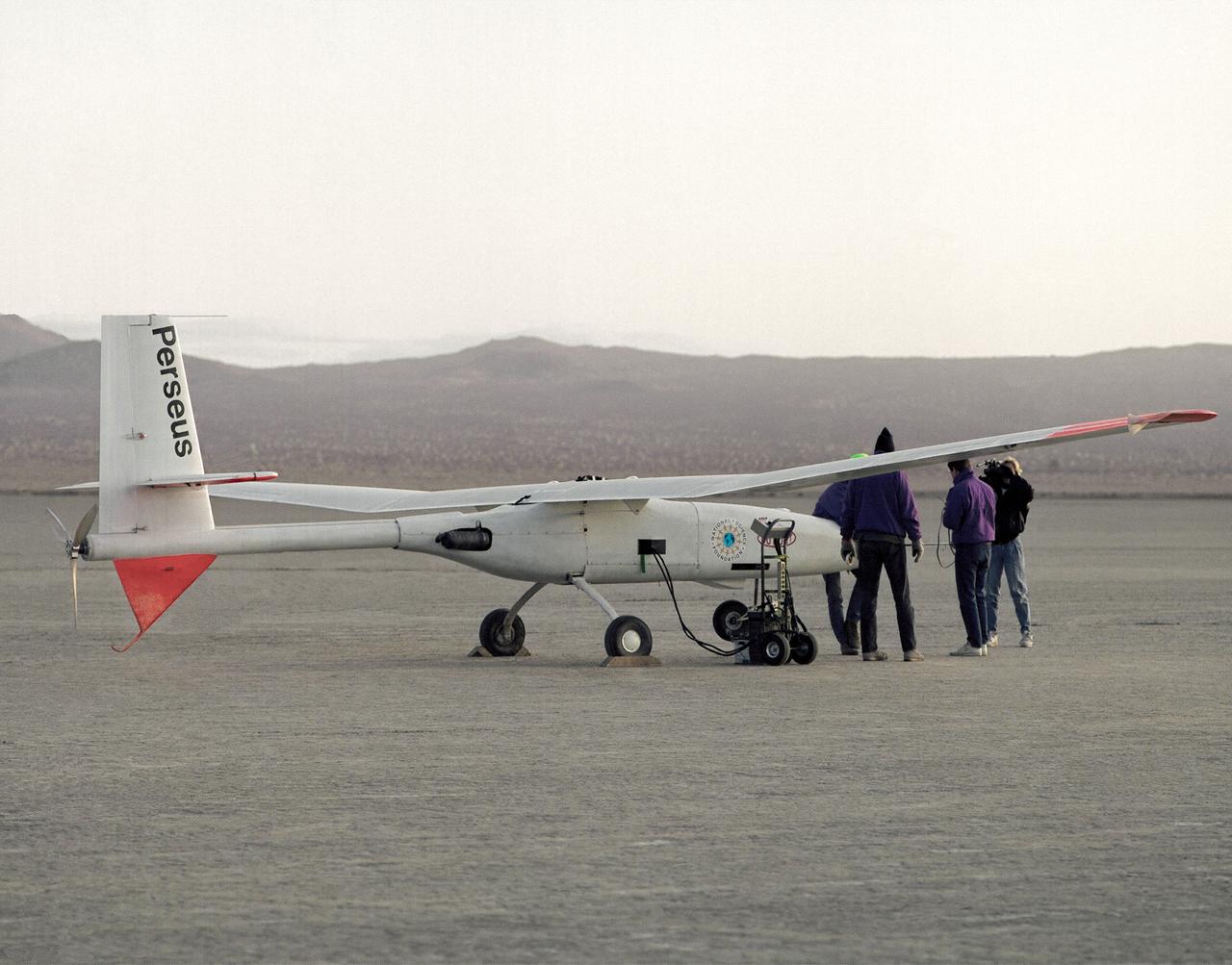
Crew members check out the Perseus proof-of-concept vehicle on Rogers Dry Lake, adjacent to the Dryden Flight Research Center, Edwards, California, after a test flight in 1991.
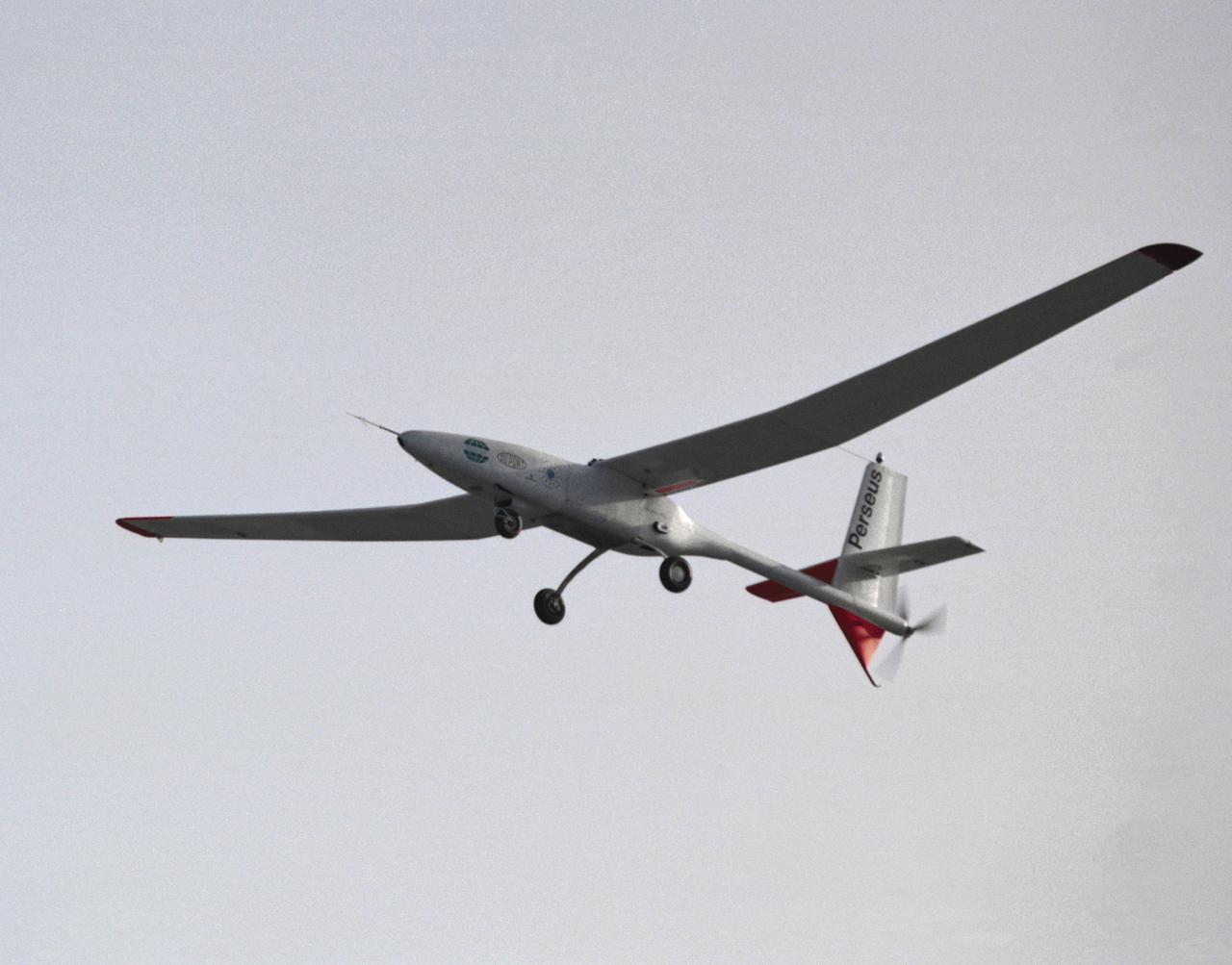
The Perseus proof-of-concept vehicle in flight at the Dryden Flight Research Center, Edwards, California in 1991. Perseus is one of several remotely-piloted aircraft designed for high-altitude, long-endurance scientific sampling missions being evaluated under the ERAST program.
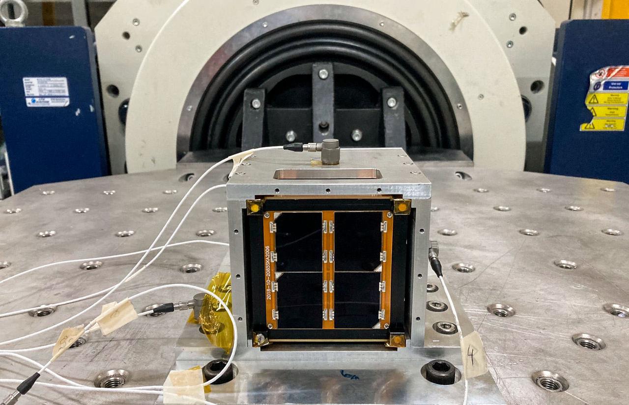
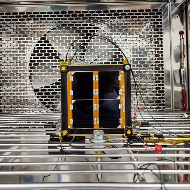
jsc2022e068265 (3/1/2022) --- A preflight view of the Surya Satellite-1 (SS-1) during Vibration Testing. The Surya Satellite-1 (SS-1) is the first Indonesian nanosatellite developed by university students at Surya University. SS-1 tests a satellite telecommunication system to serve amateur radio stations, and serves as a proof of concept of sensoric information transfer in rural areas for disaster mitigation application. Image Courtesy of The SS-1 Team.

jsc2022e068261 (11/1/2021) --- The Surya Satellite-1 and its developer team after Vibration Testing, shown left to right: Afiq, Roberto, Setra, Suhan, Hery, Zulfa. The Surya Satellite-1 (SS-1) is the first Indonesian nanosatellite developed by university students at Surya University. SS-1 tests a satellite telecommunication system to serve amateur radio stations, and serves as a proof of concept of sensoric information transfer in rural areas for disaster mitigation application. Image Courtesy of The SS-1 Team.
jsc2022e068264 (12/1/2021) --- A preflight view of the Surya Satellite-1 (SS-1) during Thermal Testing. The Surya Satellite-1 (SS-1) is the first Indonesian nanosatellite developed by university students at Surya University. SS-1 tests a satellite telecommunication system to serve amateur radio stations, and serves as a proof of concept of sensoric information transfer in rural areas for disaster mitigation application. Image Courtesy of The SS-1 Team.
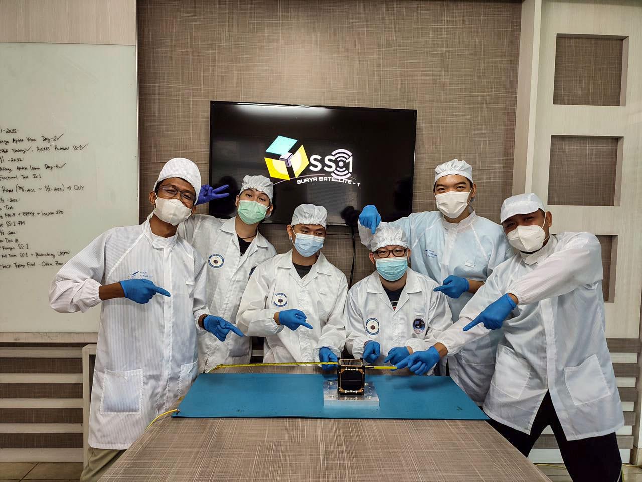
jsc2022e068260 (11/1/2021) --- The Surya Satellite-1 and its Developer Team After Deployment Testing, shown left to right: Zulfa, Hery, Setra, Roberto, Suhan, Afiq. The Surya Satellite-1 (SS-1) is the first Indonesian nanosatellite developed by university students at Surya University. SS-1 tests a satellite telecommunication system to serve amateur radio stations, and serves as a proof of concept of sensoric information transfer in rural areas for disaster mitigation application. Image Courtesy of The SS-1 Team.
The Magnetically Damped Furnace (MDF) breadboard is being developed in response to NASA's mission and goals to advance the scientific knowledge of microgravity research, materials science, and related technologies. The objective of the MDF is to dampen the fluid flows due to density gradients and surface tension gradients in conductive melts by introducing a magnetic field during the sample processing. The MDF breadboard will serve as a proof of concept that the MDF performance requirements can be attained within the International Space Station resource constraints.
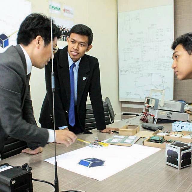
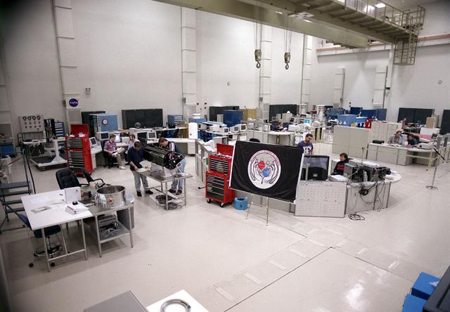
jsc2022e068262 (5/1/2022) --- A view of the SS-1 Team during the JAXA Safety Review. The Surya Satellite-1 (SS-1) is the first Indonesian nanosatellite developed by university students at Surya University. SS-1 tests a satellite telecommunication system to serve amateur radio stations, and serves as a proof of concept of sensoric information transfer in rural areas for disaster mitigation application. Image Courtesy of The SS-1 Team.
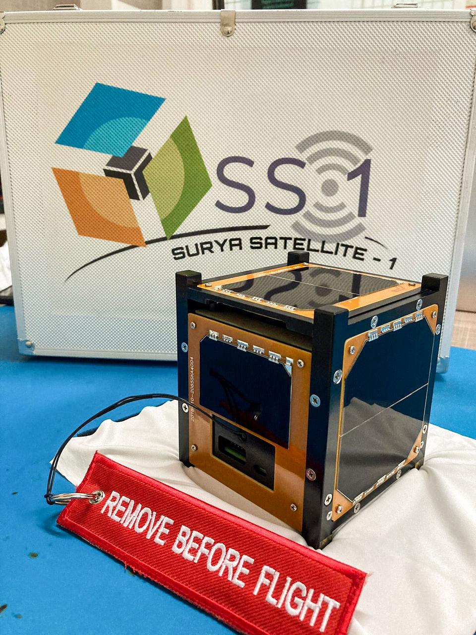
jsc2022e068263 (5/1/2022) --- A preflight view of the Surya Satellite-1 (SS-1) Flight Model. The Surya Satellite-1 (SS-1) is the first Indonesian nanosatellite developed by university students at Surya University. SS-1 tests a satellite telecommunication system to serve amateur radio stations, and serves as a proof of concept of sensoric information transfer in rural areas for disaster mitigation application. Image Courtesy of The SS-1 Team.
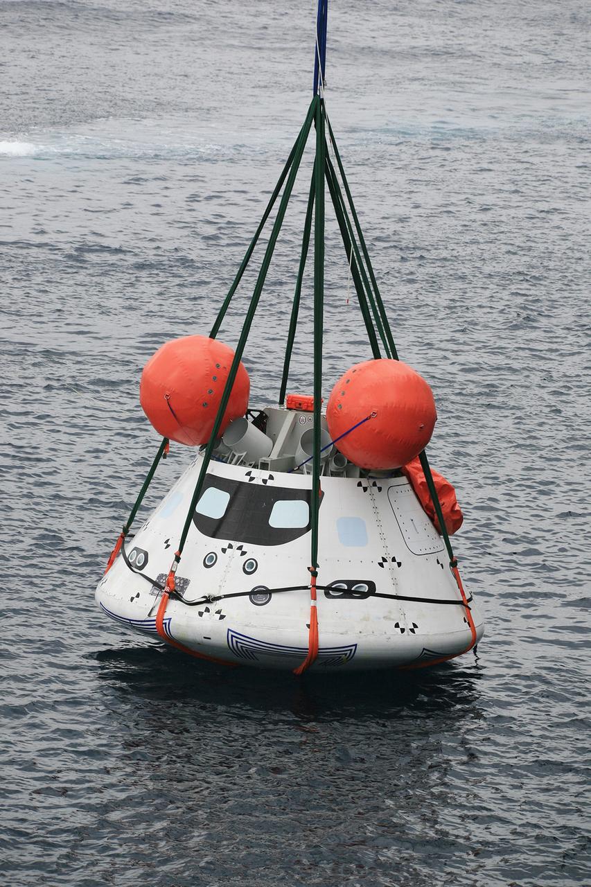
SAN DIEGO, Calif. – The Orion boilerplate test vehicle is slightly lifted by crane from the water to test the proof of concept basket lift method during an evolution of the Underway Recovery Test near the USS Anchorage in the Pacific Ocean off the coast of San Diego. NASA, Lockheed Martin and the U.S. Navy are conducting the test to prepare for recovery of the Orion crew module on its return from a deep space mission. The underway recovery test will allow the teams to demonstrate and evaluate the recovery processes, procedures, new hardware and personnel in open waters. The Ground Systems Development and Operations Program is conducting the underway recovery test. Orion is the exploration spacecraft designed to carry astronauts to destinations not yet explored by humans, including an asteroid and Mars. It will have emergency abort capability, sustain the crew during space travel and provide safe re-entry from deep space return velocities. The first unpiloted test flight of the Orion is scheduled to launch in 2014 atop a Delta IV rocket and in 2017 on NASA’s Space Launch System rocket. For more information, visit http://www.nasa.gov/orion. Photo credit: NASA/Kim Shiflett
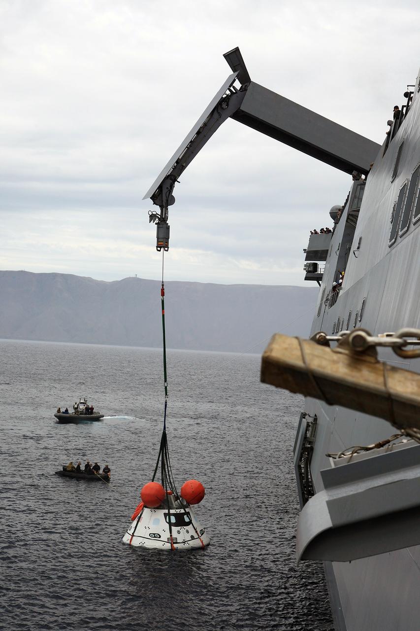
SAN DIEGO, Calif. – The Orion boilerplate test vehicle is slightly lifted by crane from the water to test the proof of concept basket lift method during an evolution of the Underway Recovery Test 2 near the USS Anchorage in the Pacific Ocean off the coast of San Diego. U.S. Navy personnel are nearby in two rigid hull inflatable boats. NASA, Lockheed Martin and the U.S. Navy are conducting the test to prepare for recovery of the Orion crew module on its return from a deep space mission. The underway recovery test will allow the teams to demonstrate and evaluate the recovery processes, procedures, new hardware and personnel in open waters. The Ground Systems Development and Operations Program is conducting the underway recovery test. Orion is the exploration spacecraft designed to carry astronauts to destinations not yet explored by humans, including an asteroid and Mars. It will have emergency abort capability, sustain the crew during space travel and provide safe re-entry from deep space return velocities. The first unpiloted test flight of the Orion is scheduled to launch in 2014 atop a Delta IV rocket and in 2017 on NASA’s Space Launch System rocket. For more information, visit http://www.nasa.gov/orion. Photo credit: NASA/Kim Shiflett
The M2-F1 Lifting Body is seen here under tow, high above Rogers Dry Lake near the Flight Research Center (later redesignated the Dryden Flight Research Center), Edwards, California. R. Dale Reed effectively advocated the project with the support of NASA research pilot Milt Thompson. Together, they gained the support of Flight Research Center Director Paul Bikle. After a six-month feasibility study, Bikle gave approval in the fall of 1962 for the M2-F1 to be built.

The XV-15 tilt rotor ships #1 and #2 parked on the NASA Dryden Flight Research Center ramp. The XV-15s, manufactured by Bell, were involved in limited research at Dryden in 1980 and 1981. The development of the XV-15 Tiltrotor research aircraft was initiated in 1973 with joint Army/NASA funding as a "proof of concept", or "technology demonstrator" program, with two aircraft being built by Bell Helicopter Textron (BHT) in 1977. The aircraft are powered by twin Lycoming T-53 turboshaft engines that are connected by a cross-shaft and drive three-bladed, 25 ft diameter metal rotors (the size extensively tested in a wind tunnel). The engines and main transmissions are located in wingtip nacelles to minimize the operational loads on the cross-shaft system and, with the rotors, tilt as a single unit. For takeoff, the proprotors and their engines are used in the straight-up position where the thrust is directed downward. The XV-15 then climbs vertically into the air like a helicopter. In this VTOL mode, the vehicle can lift off and hover for approximately one hour. Once off the ground, the XV-15 has the ability to fly in one of two different modes. It can fly as a helicopter, in the partially converted airplane mode. The XV-15 can also then convert from the helicopter mode to the airplane mode. This is accomplished by continuous rotation of the proprotors from the helicopter rotor position to the conventional airplane propeller position. During the ten to fifteen second conversion period, the aircraft speed increases and lift is transferred from the rotors to the wing. To land, the proprotors are rotated up to the helicopter rotor position and flown as a helicopter to a vertical landing.
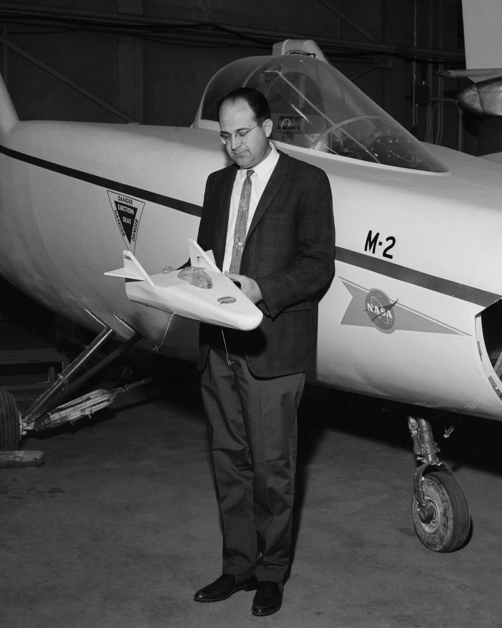
Dale Reed with a model of the M2-F1 in front of the actual lifting body. Reed used the model to show the potential of the lifting bodies. He first flew it into tall grass to test stability and trim, then hand-launched it from buildings for longer flights. Finally, he towed the lifting-body model aloft using a powered model airplane known as the "Mothership." A timer released the model and it glided to a landing. Dale's wife Donna used a 9 mm. camera to film the flights of the model. Its stability as it glided--despite its lack of wings--convinced Milt Thompson and some Flight Research Center engineers including the center director, Paul Bikle, that a piloted lifting body was possible.
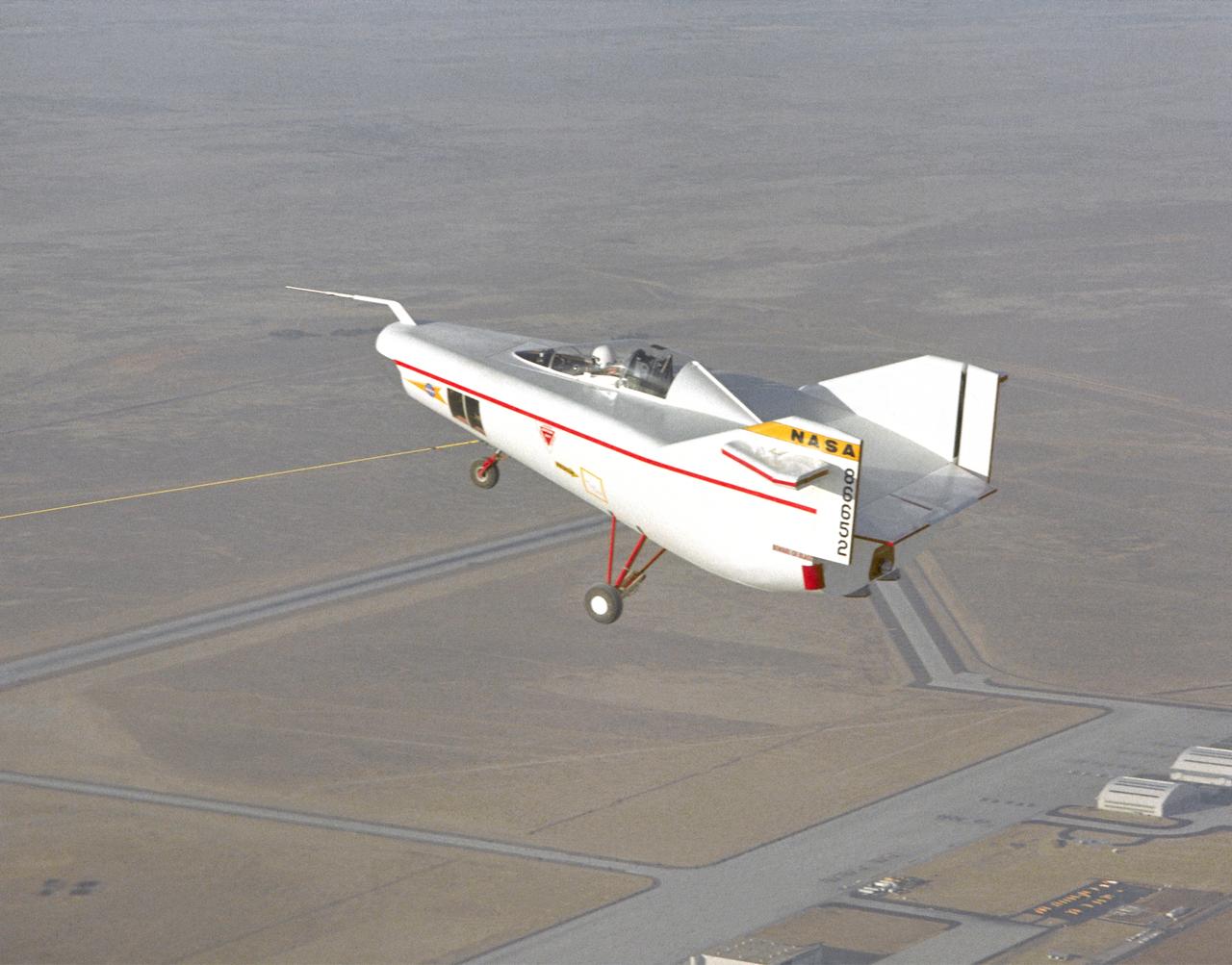
The M2-F1 Lifting Body is seen here under tow by an unseen C-47 at the NASA Flight Research Center (later redesignated the Dryden Flight Research Center), Edwards, California. The low-cost vehicle was the first piloted lifting body to be test flown. The lifting-body concept originated in the mid-1950s at the National Advisory Committee for Aeronautics' Ames Aeronautical Laboratory, Mountain View California. By February 1962, a series of possible shapes had been developed, and R. Dale Reed was working to gain support for a research vehicle.

Deep Space Station 13 (DSS-13) at NASA's Goldstone Deep Space Communications Complex near Barstow, California – part of the agency's Deep Space Network – is a 34-meter (112-foot) experimental antenna that has been retrofitted with an optical terminal (the boxy instrument below the center of the antenna's dish). Since November 2023, DSS-13 has been tracking the downlink laser of the Deep Space Optical Communications (DSOC) experiment that is aboard NASA's Psyche mission, which launched on Oct. 13, 2023. In a first, the antenna also synchronously received radio-frequency signals from the spacecraft as it travels through deep space on its way to investigate the metal-rich asteroid Psyche. The laser signal collected by the camera is then transmitted through optical fiber that feeds into a cryogenically cooled semiconducting nanowire single photon detector. Designed and built by JPL's Microdevices Laboratory, the detector is identical to the one used at Caltech's Palomar Observatory, in San Diego County, California, that acts as DSOC's downlink ground station. Goldstone is one of three complexes that comprise NASA's Deep Space Network, which provides radio communications for all of the agency's interplanetary spacecraft and is also utilized for radio astronomy and radar observations of the solar system and the universe. NASA's Jet Propulsion Laboratory, a division of Caltech in Pasadena, California, manages the DSN for the agency. https://photojournal.jpl.nasa.gov/catalog/PIA26148