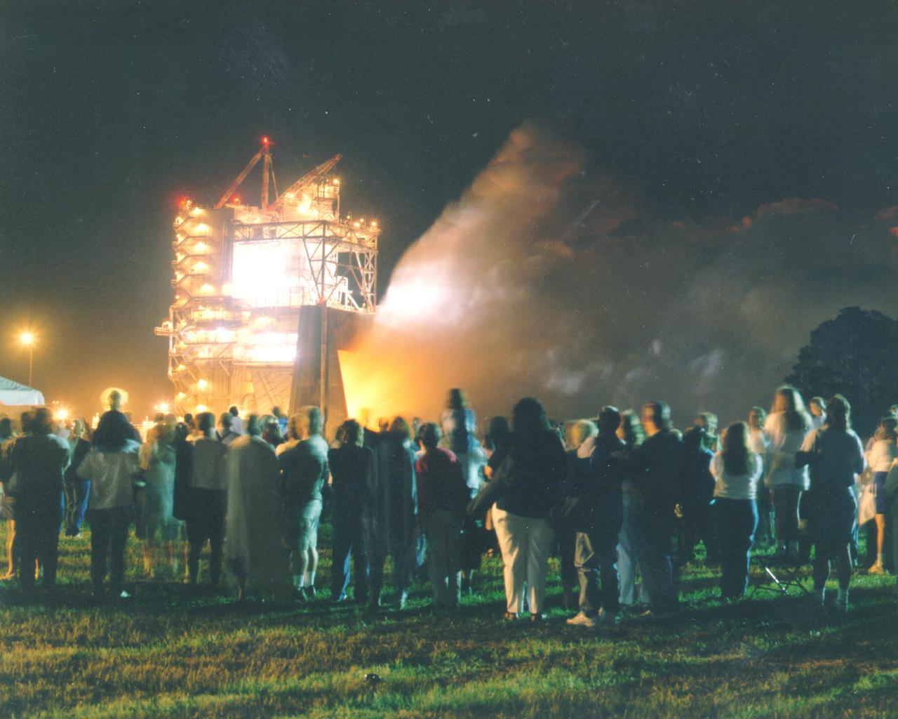
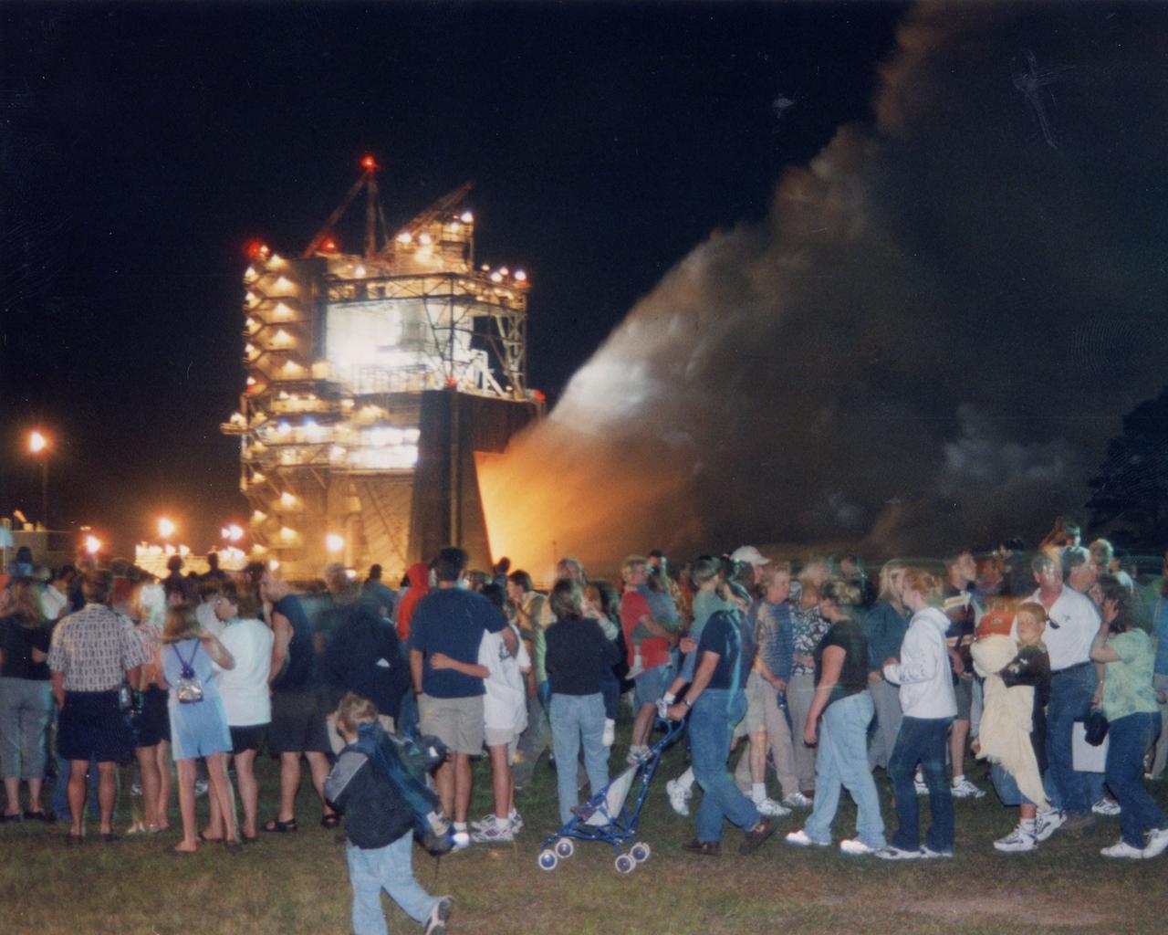
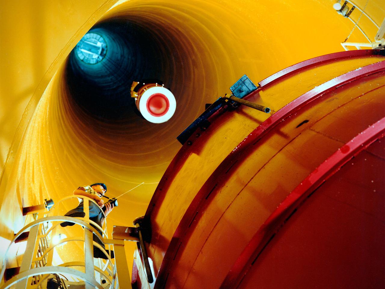
Thousands of people watch the first-ever evening public engine test of a Space Shuttle Main Engine at NASA's John C. Stennis Space Center. The spectacular test marked Stennis Space Center's 20th anniversary celebration of the first Space Shuttle mission.
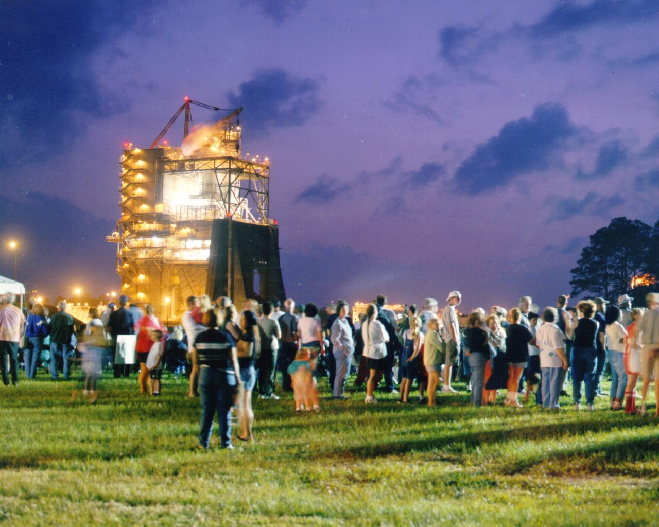
Over the past year, more than 20,000 people came to Stennis Space Center to witness the 'shake, rattle and roar' of one of the world's most sophisticated engines. Stennis Space Center in south Mississippi is NASA's lead center for rocket propulsion testing. StenniSphere, the visitor center for Stennis Space Center, hosted more than 250,000 visitors in its first year of operation. Of those visitors, 26.4 percent were from Louisiana.
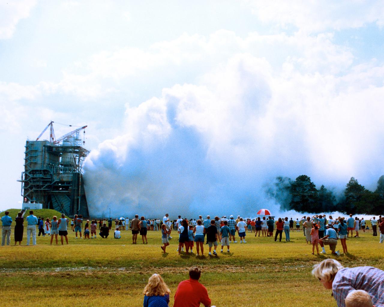
A new NASA Space Shuttle Main Engine (SSME) roars to the approval of more than 2,000 people who came to John C. Stennis Space Center in Hancock County, Miss., on July 25 for a flight-certification test of the SSME Block II configuration. The engine, a new and significantly upgraded shuttle engine, was delivered to NASA's Kennedy Space Center in Florida for use on future shuttle missions. Spectators were able to experience the 'shake, rattle and roar' of the engine, which ran for 520 seconds - the length of time it takes a shuttle to reach orbit.
Approximately 13,000 people fill the grounds at NASA's John C. Stennis Space Center for the first-ever evening public engine test of a Space Shuttle Main Engine. The test marked Stennis Space Center's 20th anniversary celebration of the first Space Shuttle mission.
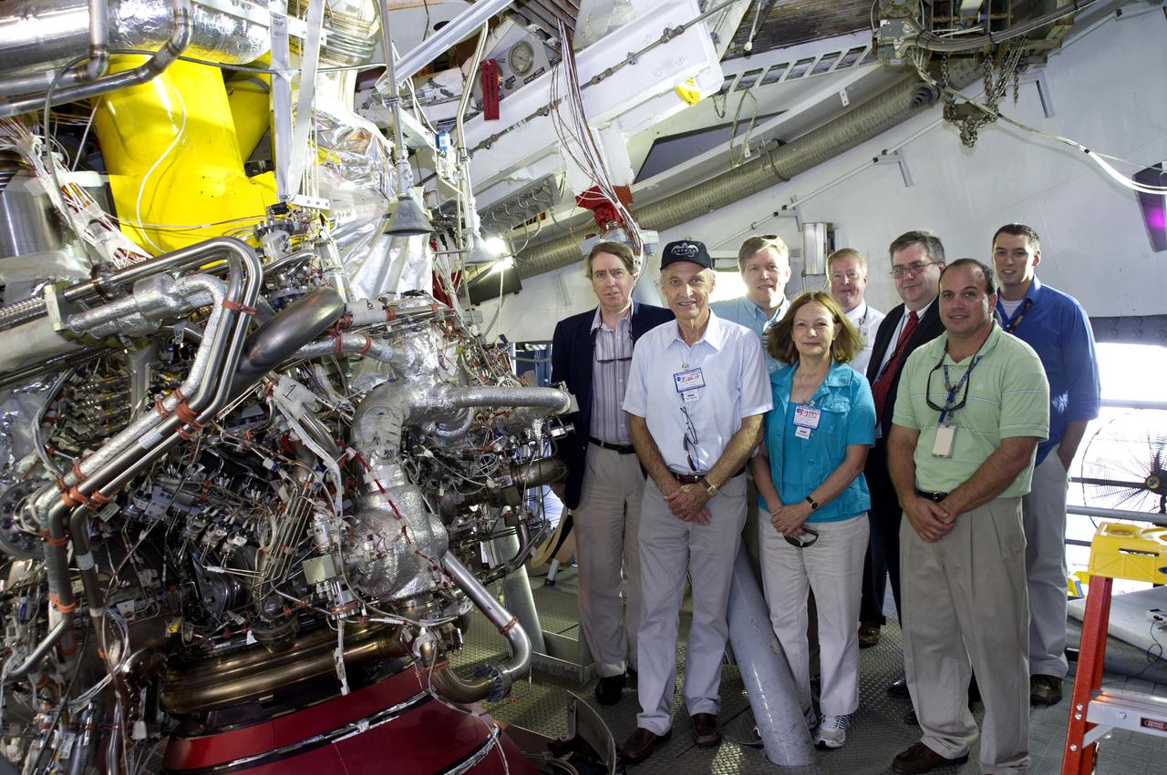
Four members of the National Research Council visited Stennis Space Center on Aug. 22, touring test stands and facilities, and holding roundtable discussions with Stennis leaders. The NRC mission is to improve government decision making and public policy, increase public understanding, and promote the acquisition and dissemination of knowledge in matters involving science, engineering, technology and health.
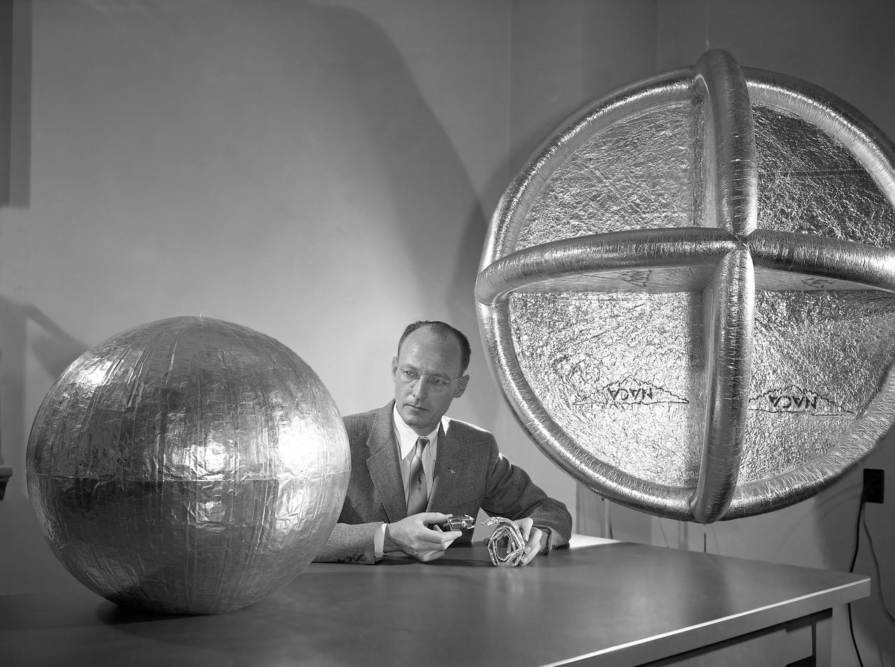
L57-525 Engineer W.J. O Sullivan, Jr., looks at inflated 20 inch subsatellite while holding inflation bottle and folded duplicate copy, February 1957. Photograph published in A New Dimension Wallops Island Flight Test Range: The First Fifteen Years by Joseph Shortal. A NASA publication. Page 601.
Mechanical engineering and integration technician, Lucas Keim, holds up a piece of ground support equipment during a proof test at Goddard Space Flight Center, Greenbelt Md., June 22, 2023. This photo has been reviewed by OSAM1 project management and the Export Control Office and is released for public view. NASA/Mike Guinto
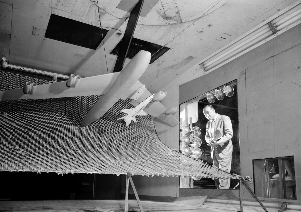
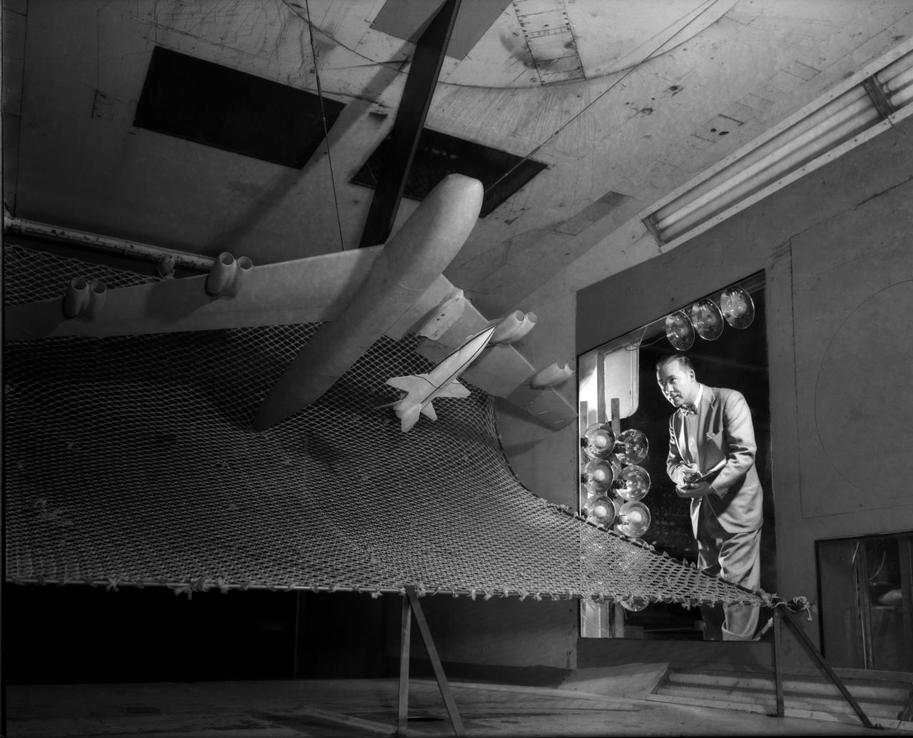
The Mercury space capsule undergoing tests in Full Scale Wind Tunnel, January 1959. Photograph published in Winds of Change, 75th Anniversary NASA publication, page 75, by James Schultz. Also Photograph published in Engineer in Charge: A History of the Langley Aeronautical Laboratory, 1917-1958, page 389, by James R. Hansen.

Flight evaluation and comparison of a NACA submerged inlet and a scoop inlet on the North American YF-93A (AF48-317 NACA-139). The YF-93A's were the first aircraft to use flush NACA engine inlets. aircraft to use flush NACA engine inlets. Note: Used in publication in Flight Research at Ames; 57 Years of Development and Validation of Aeronautical Technology NASA SP-1998-3300 and Memoirs of a Flight Test Engineer NASA SP-2001-4525
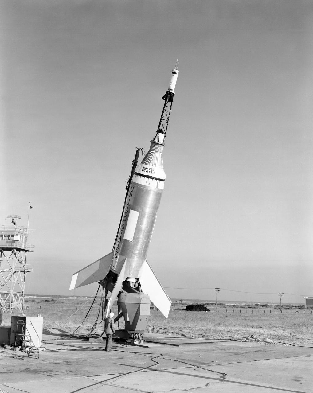
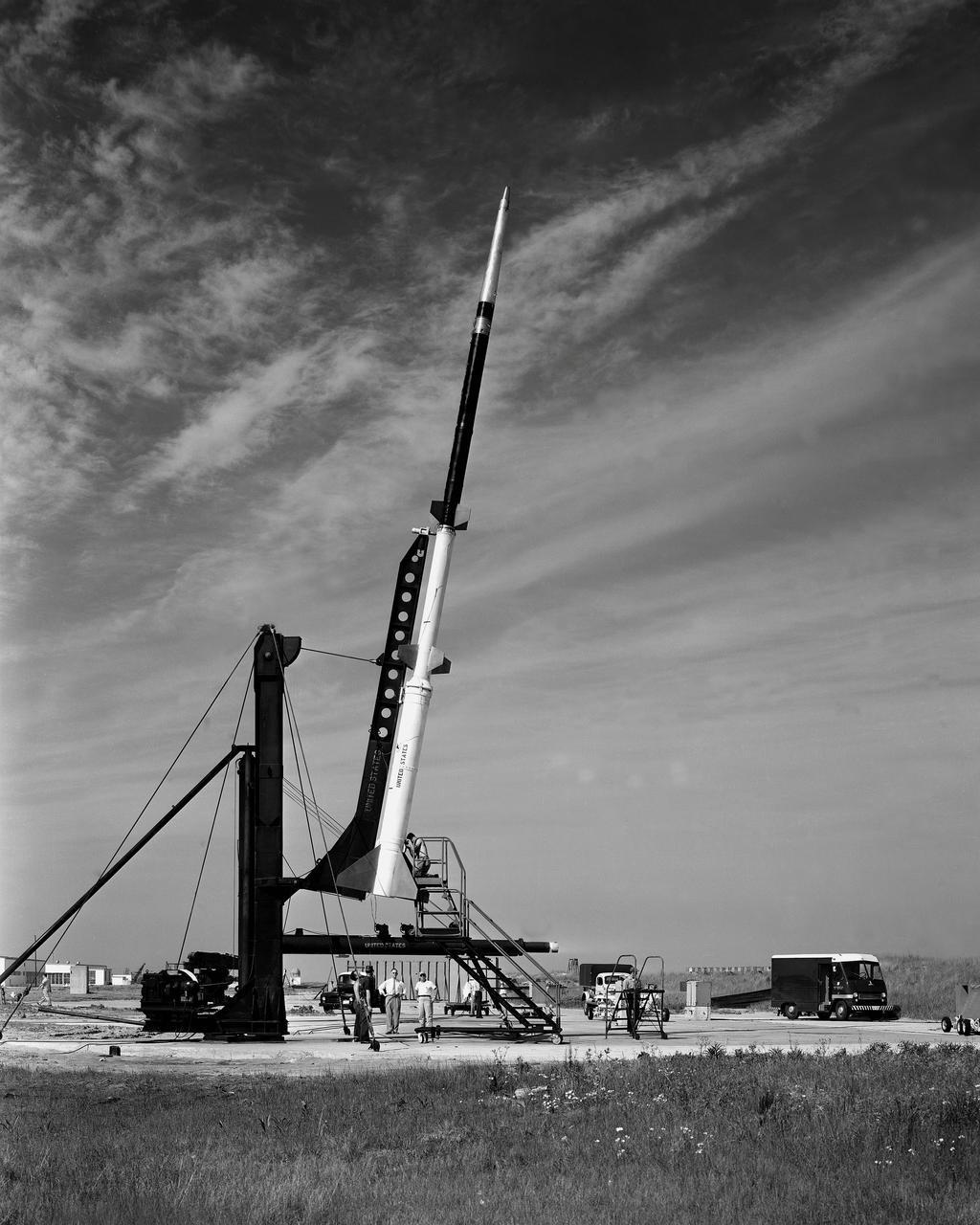
The Little Joe launch vehicle being readied for a test launch from Wallops in January 1960... Page 77. Photograph published in Winds of Change, 75th Anniversary NASA publication, by James Schultz. **note - see L59-5137 page 77 also. Photograph published in Engineer in Charge: A History of the Langley Aeronautical Laboratory, 1917-1958 by James R. Hansen. Page 389. ...was conceived by Langley engineers Max Faget and Paul Purser even before STG (Space Task Group) was organized.
L59-3896 Engineers W. N. Gardner and C.A. Brown, Jr., check operations as Trailblazer 1b is readied for Flight, June 4, 1959. Photograph published in A New Dimension Wallops Island Flight Test Range: The First Fifteen Years by Joseph Shortal. A NASA publication, page 675. D58-3001 Model. Engineers W. N. Gardner and C.A. Brown
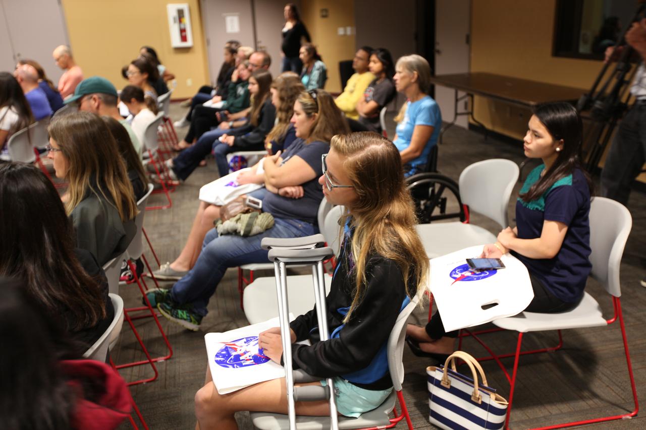
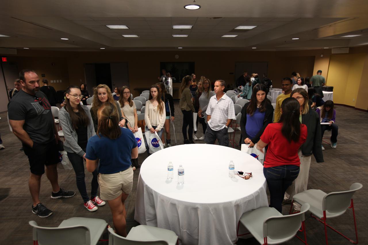
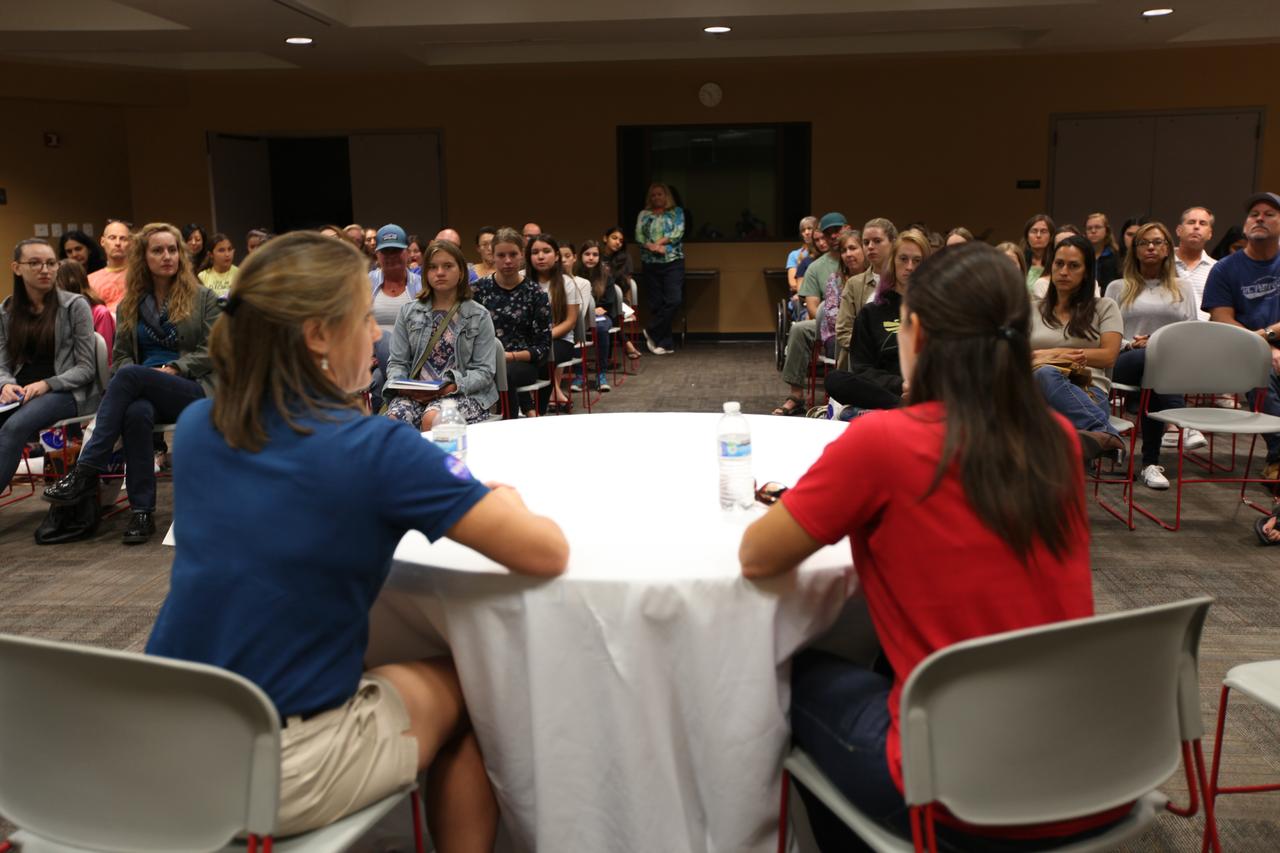
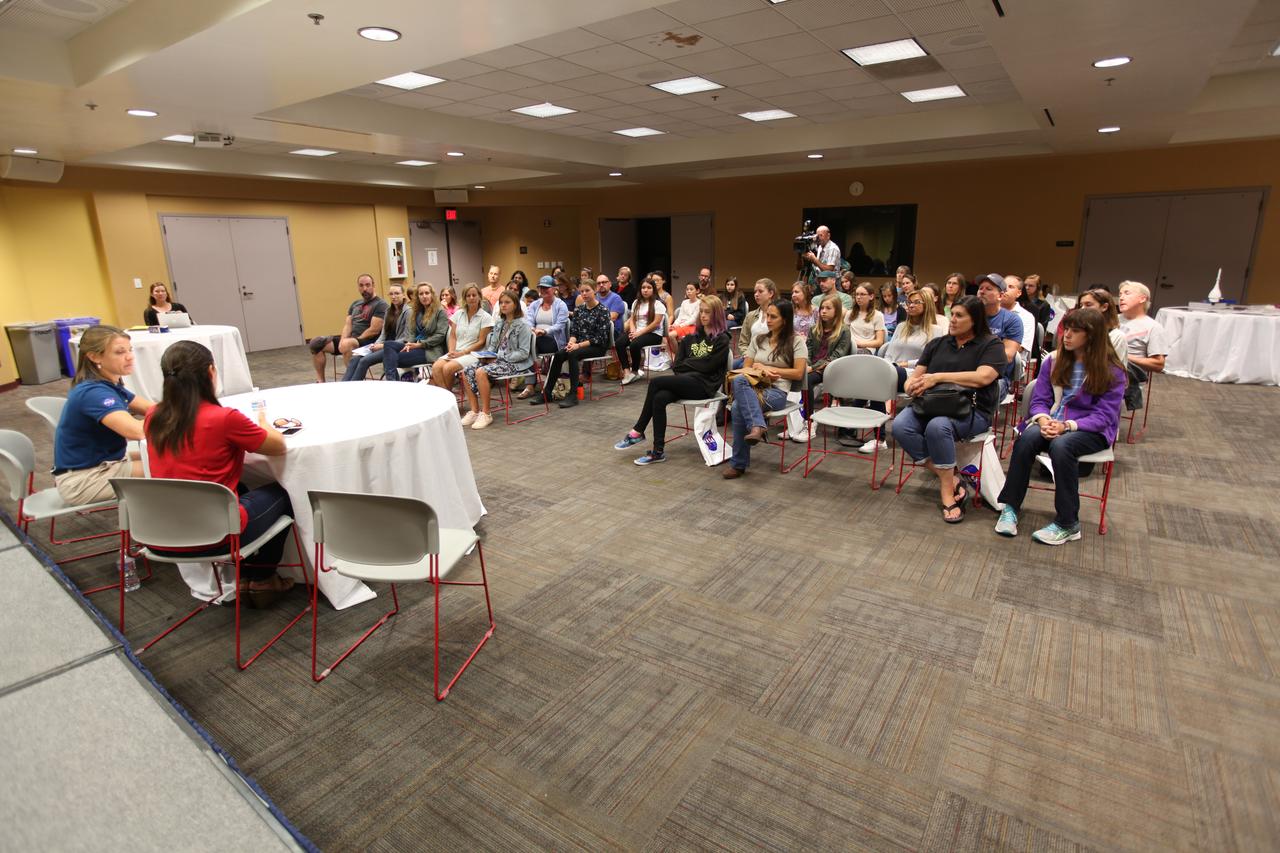
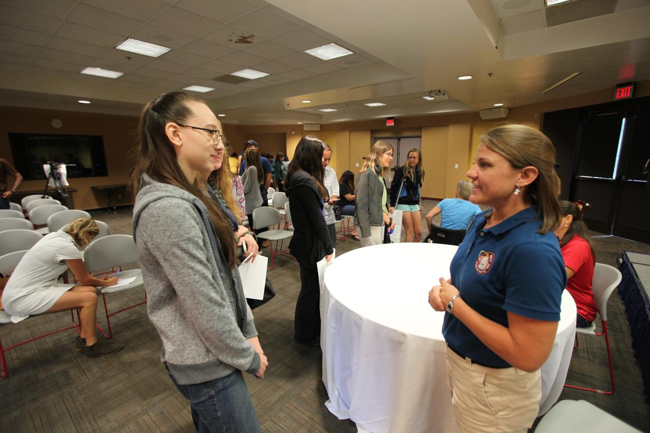
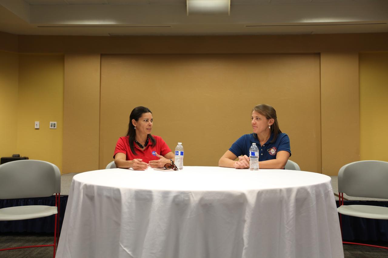
Take Our Children to Work Day participants join NASA Stennis federal city employees for a career panel discussion on June 27. The career panel discussion included (left to right): Rebecca Mataya, NASA Stennis budget analyst; Madison Rundell, Aerojet Rocketdyne information technology specialist; Troy Chivers, COLSA/All In Solutions representative; Clyde Conerly, Lockheed Martin quality engineer; Andy Guymon, Relativity Space test engineer; and moderator Apolonia Acker, NASA Stennis public affairs specialist.
NACA Photographer Thrust reverser on F-94C-1 (AF50-956 NACA 156) Starfire (l to R) Air Force Major E. Sommerich; Ames Engineer Seth Anderson, Lt. Col. Tavasti; and Ames Chief test pilot George Cooper discussing phases of flight evaluation tests. Note: Used in publication in Flight Research at Ames; 57 Years of Development and Validation of Aeronautical Technology NASA SP-1998-3300 fig 91
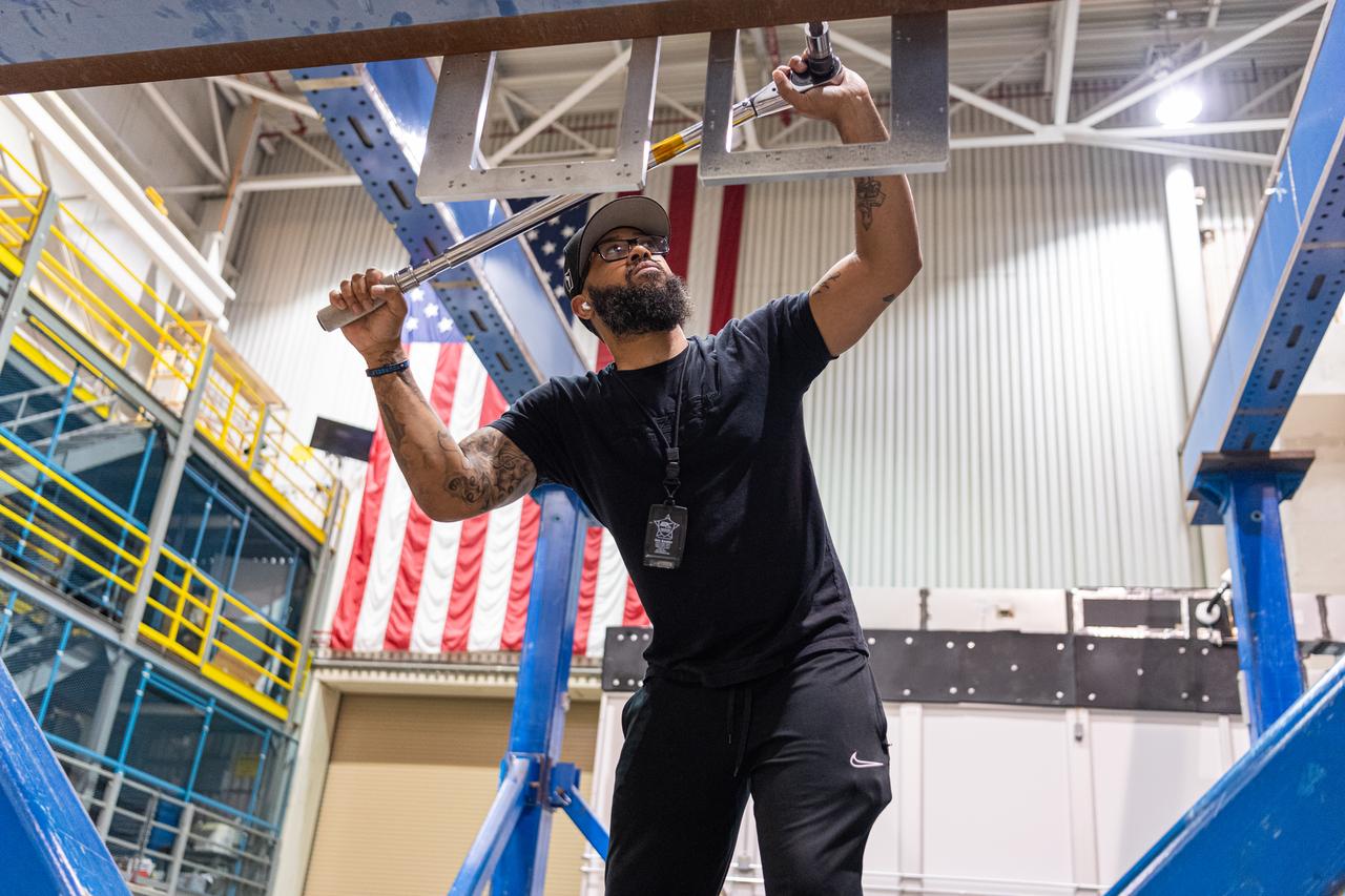
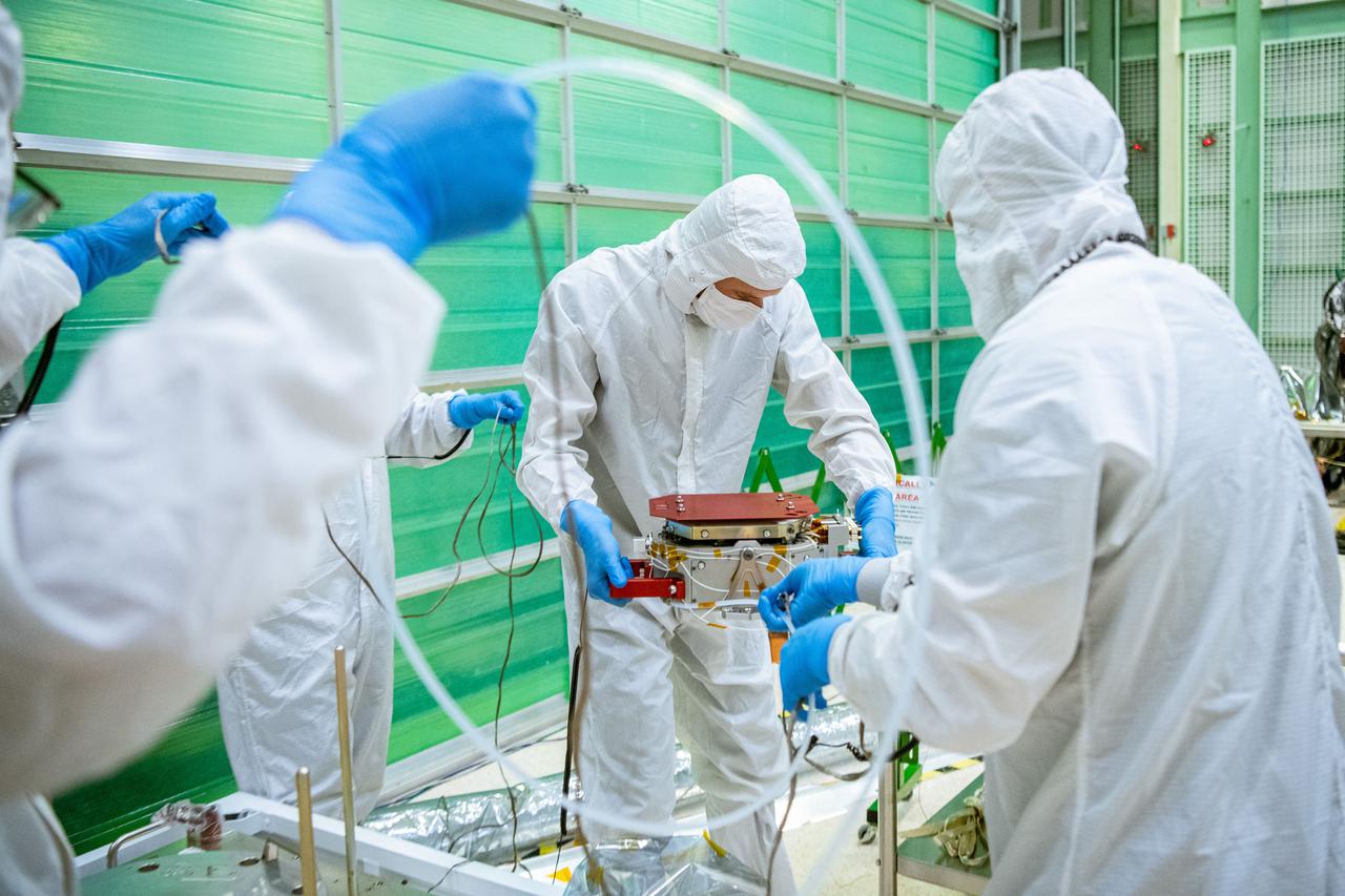
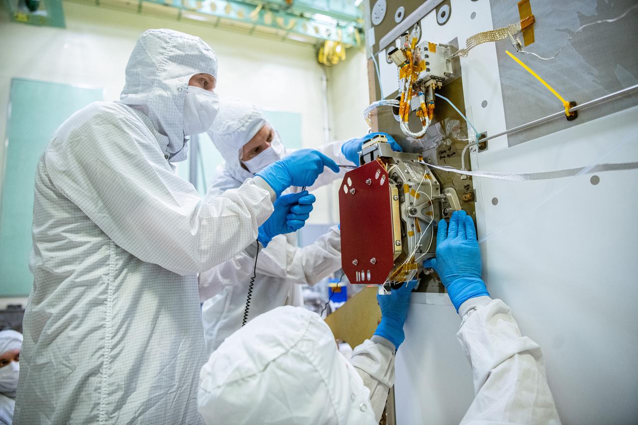
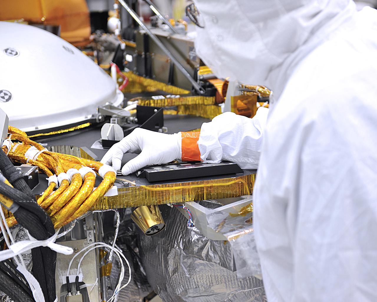
Mechanical engineering and integration technician Ivan Pratt installs brackets onto the static load testing platform in preparation of an OSAM-1 ground support equipment proof test at Goddard Space Flight Center, Greenbelt Md., July 19, 2023. This photo has been reviewed by OSAM1 project management and the Export Control Office and is released for public view. NASA/Mike Guinto
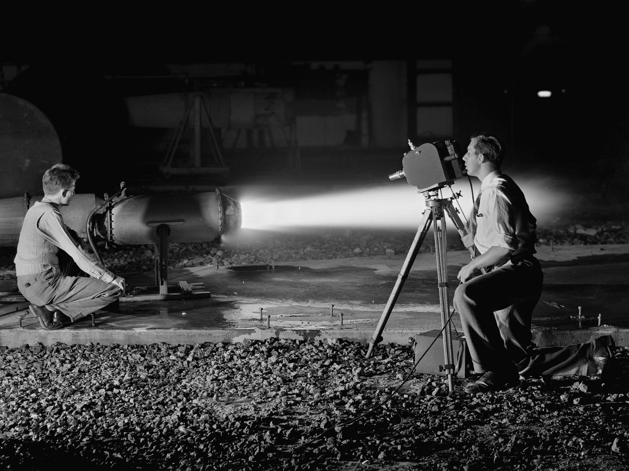
A National Advisory Committee for Aeronautics (NACA) photographer films the test of a ramjet engine at the Lewis Flight Propulsion Laboratory. The laboratory had an arsenal of facilities to test the engines and their components, and immersed itself in the study of turbojet and ramjet engines during the mid-1940s. Combustion, fuel injection, flameouts, and performance at high altitudes were of particular interest to researchers. They devised elaborate schemes to instrument the engines in order to record temperature, pressure, and other data. Many of the tests were also filmed so Lewis researchers could visually review the combustion performance along with the data. The photographer in this image was using high-speed film to document a thrust augmentation study at Lewis’ Jet Static Propulsion Laboratory. The ramjet in this photograph was equipped with a special afterburner as part of a general effort to improve engine performance. Lewis’ Photo Lab was established in 1942. The staff was expanded over the next few years as more test facilities became operational. The Photo Lab’s staff and specialized equipment have been key research tools for decades. They accompany pilots on test flights, use high-speed cameras to capture fleeting processes like combustion, and work with technology, such as the Schlieren camera, to capture supersonic aerodynamics. In addition, the group has documented construction projects, performed publicity work, created images for reports, and photographed data recording equipment.
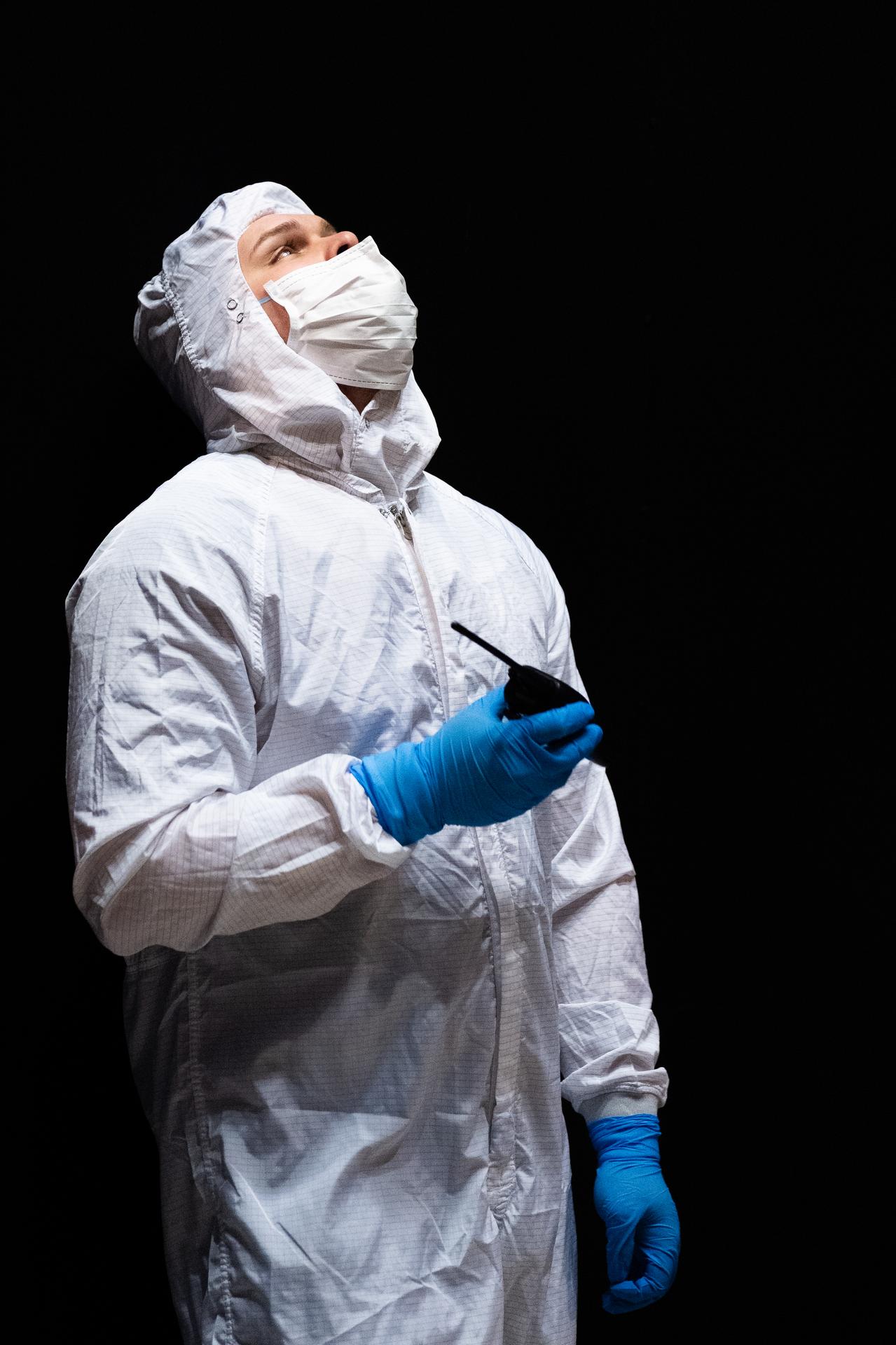
Mechanical engineering and integration technician, Lucas Keim, directs the crane operator from inside the thermal vacuum chamber in support of OSAM-1 environmental testing operations at Goddard Space Flight Center, Greenbelt Md., Nov 30, 2023. This photo has been reviewed by OSAM1 project management and the Export Control Office and is released for public view. NASA/Mike Guinto
Mechanical Integration and Testing Engineer, Jeff Geroso, watches as the OSAM-1 spacecraft arrives at Goddard Space Flight Center, Greenbelt, Md., Sept 20, 2023. Geroso is responsible for the receiving operations involving the OSAM-1 spacecraft bus. This photo has been reviewed by OSAM1 project management and the Export Control Office and is released for public view. NASA/ Mike Guinto
A one-twentieth scale model of the X-15 originally suspended beneath the wing of a B-52 is observed by a scientist of the National Aeronautics and Space Administration (NASA) as it leaves the bomber model in tests to determine the release characteristics and drop motion of the research airplane. Caption: The aerodynamics of air launching the North American X-15 being investigated in the 300MPH Low Speed 7x10 Tunnel, about 1957. Photograph published in Engineer in Charge: A History of the Langley Aeronautical Laboratory, 1917-1958 by James R. Hansen. Page 366. Photograph also published in Sixty Years of Aeronautical Research 1917-1977 By David A. Anderton. A NASA publication. Page 49.
A one-twentieth scale model of the X-15 originally suspended beneath the wing of a B-52 is observed by a scientist of the National Aeronautics and Space Administration (NASA) as it leaves the bomber model in tests to determine the release characteristics and drop motion of the research airplane. Caption: The aerodynamics of air launching the North American X-15 being investigated in the 300MPH Low Speed 7x10 Tunnel, about 1957. Photograph published in Engineer in Charge: A History of the Langley Aeronautical Laboratory, 1917-1958 by James R. Hansen. Page 366. Photograph also published in Sixty Years of Aeronautical Research 1917-1977 By David A. Anderton. A NASA publication. Page 49.
As part of the project FIRE study, technicians ready materials to be subjected to high temperatures that will simulate the effects of re-entry heating. Tests of various space capsule materials for Project FIRE were conducted. Photographed in the 9 X 6 Foot Thermal Structures Tunnel. Photograph published in Winds of Change, 75th Anniversary NASA publication, by James Schultz (page 78). Photograph also published in Engineer in Charge: A History of the Langley Aeronautical Laboratory, 1917-1958 by James R. Hansen (page 476). Also Published in the book " A Century at Langley" by Joseph Chambers. Pg. 92
CAPE CANAVERAL, Fla. – Mike Curie (left), with NASA Public Affairs, introduces NASA managers following their day-long Flight Readiness Review of space shuttle Discovery for the STS-119 mission. Next to Curie are (from left) William H. Gerstenmaier, associate administrator for Space Operations, John Shannon, Shuttle Program manager, Mike Suffredini, program manager for the International Space Station, and Mike Leinbach, shuttle launch director. NASA managers decided to plan a launch no earlier than Feb. 19, pending additional analysis and particle impact testing associated with a flow control valve in the shuttle's main engine system. Photo credit: NASA/Cory Huston
Senior Mechanical Design Engineer Alexander Eigenraam from SRON, the Netherlands Institute for Space Research, moves the SPEXone instrument before it is integrated onto the Plankton, Aerosol, Cloud, ocean Ecosystem (PACE) Spacecraft at NASA Goddard Space Flight Center in Greenbelt, Maryland on June 13th, 2022. SPEXone is one of three instruments on NASA's Plankton, Aerosol, Cloud, ocean Ecosystem (PACE) observatory and has been developed by a Dutch consortium consisting of SRON Netherlands Institute for Space Research and Airbus Defence and Space Netherlands, supported by opto-mechanical expertise from TNO. SRON and Airbus DS NL are responsible for the design, manufacturing and testing of the instrument. The scientific lead is in the hands of SRON. SPEXone is a public-private initiative, funded by the Netherlands Space Office (NSO), the Netherlands Organization of Scientific Research (NWO), SRON and Airbus DS NL.instrument. The scientific lead is in the hands of SRON. SPEXone is a public-private initiative, funded by the Netherlands Space Office (NSO), the Netherlands Organization of Scientific Research (NWO), SRON and Airbus DS NL.
CAPE CANAVERAL, Fla. – Mike Curie (far left), with NASA Public Affairs, moderates the flight readiness review news conference for space shuttle Discovery's STS-119 mission. On the panel are (from left) Associate Administrator for Space Operations Bill Gerstenmaier, Space Shuttle Program Manager John Shannon and Space Shuttle Launch Director Mike Leinbach. During a thorough review of Discovery's readiness for flight, NASA managers decided Feb. 20 more data and possible testing are required before proceeding to launch. Engineering teams have been working to identify what caused damage to a flow control valve on shuttle Endeavour during its November 2008 flight. A new launch date has not been determined. NASA managers decided Feb. 20 more data and possible testing are required before proceeding to launch. Engineering teams have been working to identify what caused damage to a flow control valve on shuttle Endeavour during its November 2008 flight. A new launch date has not been determined. Photo credit: NASA/Glenn Benson
National Aeronautics and Space Administration (NASA) photographer Arthur Laufman sets up a camera to film a Mercury capsule that was constructed by the Lewis Research Center staff. Lewis engineers and mechanics built two of the capsules for the upcoming Big Joe launches in September 1959. Big Joe was an attempt early in Project Mercury to use a full-scale Atlas booster to simulate the reentry of a mock-up Mercury capsule without actually placing it in orbit. The Photographic Branch, referred to as the Photo Lab, was part of the center’s Technical Reports Division. Originally the group performed normal and high-speed still image and motion picture photography. The photographers documented construction, performed publicity work, created images for reports, photographed data on manometer boards, and recorded test footage. Laufman joined the Photo Lab staff in 1948 and began producing full-length technical films as a tool to educate those outside of the agency on the research being conducted at Lewis. He worked with engineers to determine proper subjects for these films and develop a script. Laufman not only filmed tests, but also supporting footage of facilities, models, and staff members. He then edited the footage and added audio, visuals, and narration. The film masters were assigned standard identification numbers and add to the Photo Lab’s catalogue.
George Mazaris, works with an assistant to obtain the preliminary measurements of cadmium sulfide thin-film solar cells being tested in the Space Environmental Chamber at the National Aeronautics and Space Administration (NASA) Lewis Research Center. Lewis’ Photovoltaic Fundamentals Section was investigating thin-film alternatives to the standard rigid and fragile solar cells. The cadmium sulfide semiconductors were placed in a light, metallized substrate that could be rolled or furled during launch. The main advantage of the thin-film solar cells was their reduced weight. Lewis researchers, however, were still working on improving the performance of the semiconductor. The new thin-film solar cells were tested in a space simulation chamber in the CW-6 test cell in the Engine Research Building. The chamber created a simulated altitude of 200 miles. Sunlight was simulated by a 5000-watt xenon light. Some two dozen cells were exposed to 15 minutes of light followed by 15 minutes of darkness to test their durability in the constantly changing illumination of Earth orbit. This photograph was taken for use in a NASA recruiting publication.
National Aeronautics and Space Administration (NASA) Lewis Research Center. Lewis researchers had been studying the behavior of liquid in microgravity for several years using ballistic rocket flights, aircraft flying series of parabolas, and in the 2.2-Second Drop Tower. It was easier to control experiments and repeat tests based on almost instantaneous test results in the Zero Gravity Research Facility than missiles or aircraft. It also more than doubled the microgravity time of the original drop tower. The experiments were enclosed in a large experiment package that was suspended inside the chamber. A vacuum was introduced to the chamber before the package was released. The test equipment allowed researchers to film and take measurements of the experiment as it was falling. The 2500‐pound package was slowed by special Styrofoam‐like pellets in a decelerator cart. An experiment, traveling 176 feet per second, was stopped in about 15 feet of deceleration material. The facility’s designers struggled to determine the correct type of deceleration pellets to use. For several years Lewis engineers tested various samples from manufacturers. The final selection was not made until the facility’s completion in May 1966, just before the facility made its public debut at the 1966 Inspection of the Center.
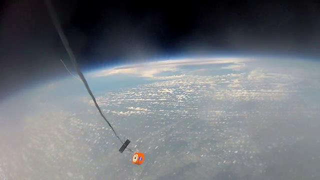
CAPE CANAVERAL, Fla. – An instrument-laden capsule begins its descent from 105,000 feet above Earth during a flight hosted by Rocket University participants. After the high-altitude balloon carrying it burst, the capsule free-fell to 50,000 feet and then deployed a parachute to land safely on the ground. The test flight was used to evaluate the stability of the capsule as it fell to Earth before its parachute opened. Rocket University is a program of courses, workshops, labs and projects offered to engineering and research pros of all stripes to keep their skills fresh and broaden their experiences. Photo credit: Courtesy of Rocket University The work is part of Transition and Retirement of the remaining space shuttles, Atlantis and Endeavour. Atlantis is being prepared for public display at Kennedy's Visitor Complex. Over the course of its 26-year career, Atlantis spent 293 days in space during 33 missions. For more information, visit http://www.nasa.gov/transition Photo credit: NASA/Kim Shiflett
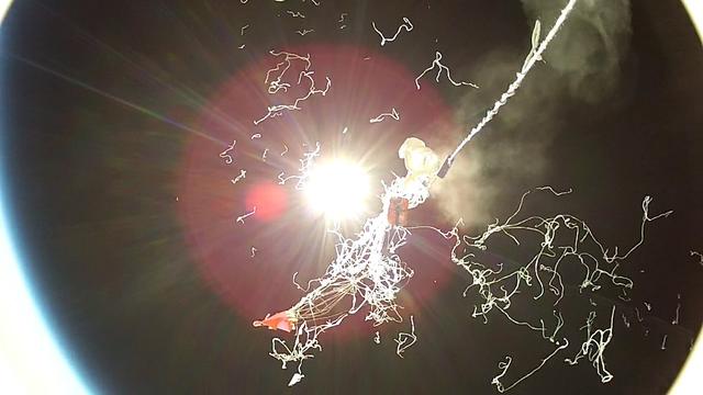
CAPE CANAVERAL, Fla. – The high-altitude balloon that carried an instrument-laden capsule bursts 105,000 feet above Earth during a flight hosted by Rocket University participants. The bursting of the balloon allowed the capsule to free-fall to 50,000 feet and then deploy a parachute to land safely on the ground. The test flight was used to evaluate the stability of an instrumented capsule as it fell to Earth before its parachute opened. Rocket University is a program of courses, workshops, labs and projects offered to engineering and research pros of all stripes to keep their skills fresh and broaden their experiences. Photo credit: Courtesy of Rocket University The work is part of Transition and Retirement of the remaining space shuttles, Atlantis and Endeavour. Atlantis is being prepared for public display at Kennedy's Visitor Complex. Over the course of its 26-year career, Atlantis spent 293 days in space during 33 missions. For more information, visit http://www.nasa.gov/transition Photo credit: NASA/Kim Shiflett
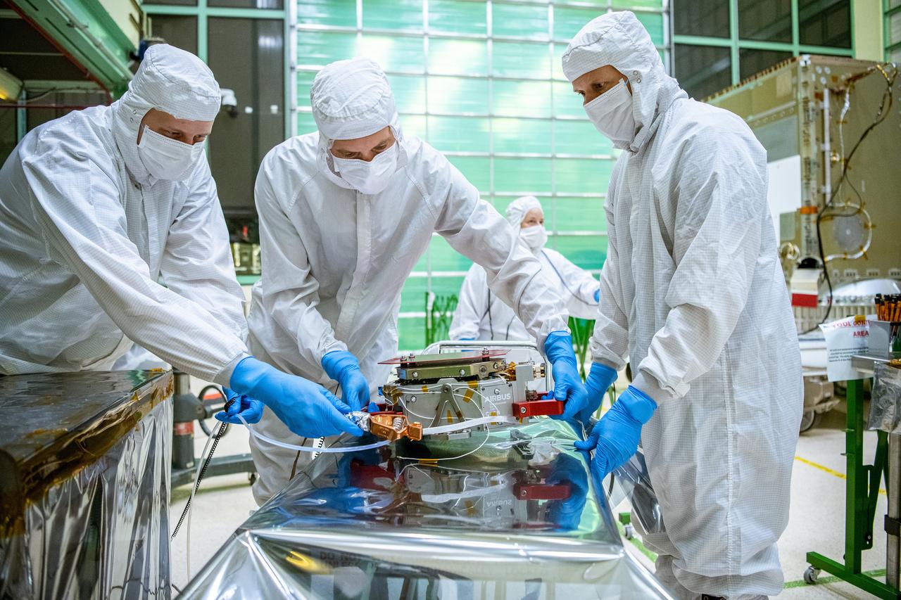
Engineers from SRON, the Netherlands Institute for Space Research, move the SPEXone instrument before it is integrated onto the Plankton, Aerosol, Cloud, ocean Ecosystem (PACE) Spacecraft at NASA Goddard Space Flight Center in Greenbelt, Maryland on June 13th, 2022. SPEXone is a compact, optical satellite instrument that will characterize aerosols from low Earth orbit as part of the NASA PACE mission. SPEXone is one of three instruments on NASA's Plankton, Aerosol, Cloud, ocean Ecosystem (PACE) observatory and has been developed by a Dutch consortium consisting of SRON Netherlands Institute for Space Research and Airbus Defence and Space Netherlands, supported by opto-mechanical expertise from TNO. SRON and Airbus DS NL are responsible for the design, manufacturing and testing of the instrument. The scientific lead is in the hands of SRON. SPEXone is a public-private initiative, funded by the Netherlands Space Office (NSO), the Netherlands Organization of Scientific Research (NWO), SRON and Airbus DS NL.
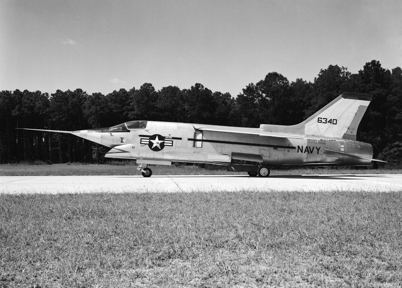
Crusader on runway. Navy aircraft number 6340. L59-6101 caption: The Navy's Vought XF8U-3 Supersonic Fighter was an entirely new design as compared to the earlier F8U Crusader series. This jet plane lost in competition with the McDonnell F4H, however, and was never put into production. Langley used the XF8U-3 in some of the first flight measurements of sonic boom intensity. Photograph published in Engineer in Charge A History of the Langley Aeronautical Laboratory, 1917-1958 by James R. Hansen. Page 507. Caption: Chance Vought F8U-3 airplane used in sonic boom investigation at Wallops, June-August 1959. Photograph published in A New Dimension Wallops Island Flight Test Range: The First Fifteen Years by Joseph Shortal. A NASA publication. Page 672.
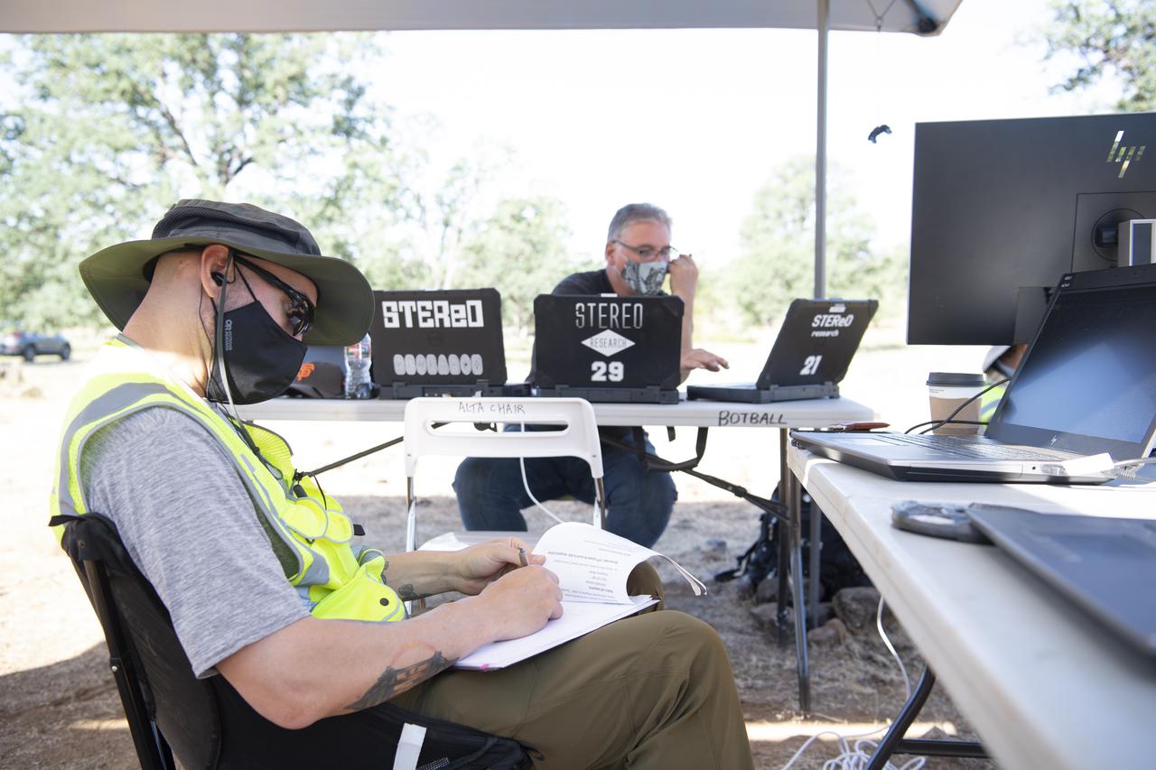
Zach Roberts, pilot computer operator for STEReO, the Scalable Traffic Management for Emergency Response Operations project, at NASA's Ames Research Center, left, Bill McCarthy, software engineer and research laptop operator for STEReO, at NASA's Ames Research Center, right, are seen during simulated drone operations as part of STEReO field testing, Wednesday, May 5, 2021 as Cal Fire conducts aerial fire fighting training exercises near Redding, California. STEReO, the Scalable Traffic Management for Emergency Response Operations project, led by NASA’s Ames Research Center, builds on NASA’s expertise in air traffic management, human factors research, and autonomous technology development to apply the agency’s work in Unmanned Aircraft Systems Traffic Management, or UTM, to public safety uses. Photo Credit: (NASA/Joel Kowsky)
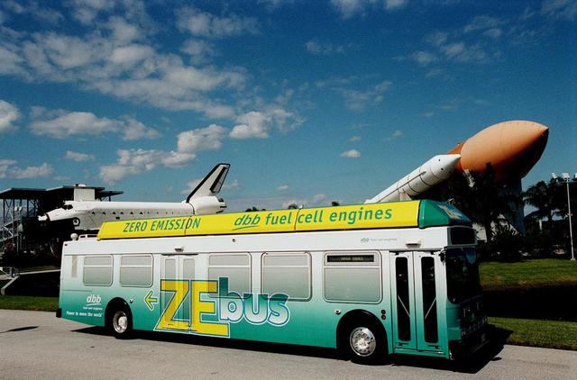
The Zero Emissions (ZE) transit bus tours the KSC Visitor Complex for a test ride. In the background are a mock-up orbiter named Explorer (left) and a stack of solid rocket boosters and external tank (right), typically used on Shuttle launches. Provided by dbb fuel cell engines inc. of Vancouver, Canada, the ZE bus was brought to KSC as part of the Center's Alternative Fuel Initiatives Program. The bus uses a Proton Exchange Membrane fuel cell in which hydrogen and oxygen, from atmospheric air, react to produce electricity that powers an electric motor drive system. The by-product "exhaust" from the fuel cell is water vapor, thus zero harmful emissions. A typical diesel-powered bus emits more than a ton of harmful pollutants from its exhaust every year. The ZE bus is being used on tour routes at the KSC Visitor Complex for two days to introduce the public to the concept
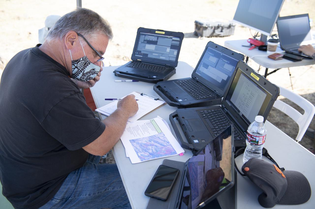
Bill McCarthy, software engineer and research laptop operator for STEReO, the Scalable Traffic Management for Emergency Response Operations project, at NASA's Ames Research Center, is seen during simulated drone operations as part of STEReO field testing, Wednesday, May 5, 2021 as Cal Fire conducts aerial fire fighting training exercises near Redding, California. STEReO, the Scalable Traffic Management for Emergency Response Operations project, led by NASA’s Ames Research Center, builds on NASA’s expertise in air traffic management, human factors research, and autonomous technology development to apply the agency’s work in Unmanned Aircraft Systems Traffic Management, or UTM, to public safety uses. Photo Credit: (NASA/Joel Kowsky)
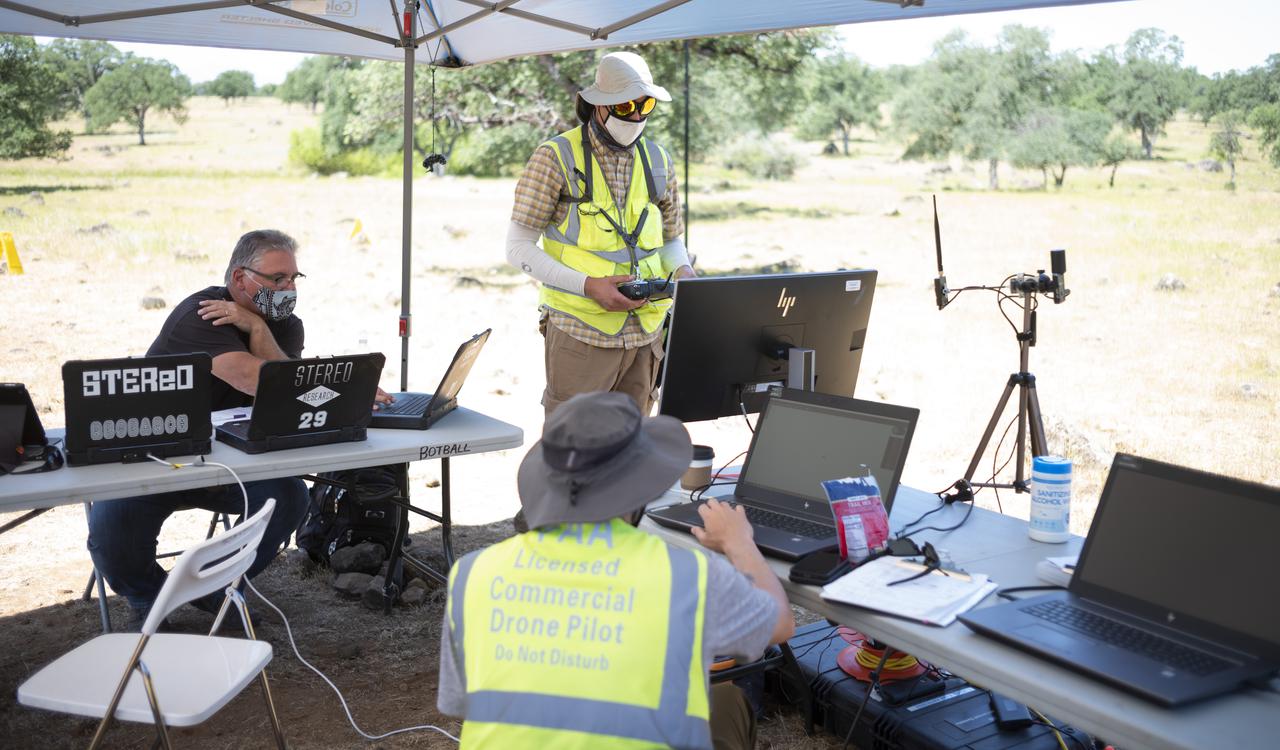
Bill McCarthy, software engineer and research laptop operator for STEReO, the Scalable Traffic Management for Emergency Response Operations project, at NASA's Ames Research Center, left, Jonas Jonsson, pilot in command for STEReO, at NASA's Ames Research Center, standing center, and Zach Roberts, pilot computer operator for STEReO, at NASA's Ames Research Center, seated center, are seen during STEReO field testing, Wednesday, May 5, 2021 as Cal Fire conducts aerial fire fighting training exercises near Redding, California. STEReO, the Scalable Traffic Management for Emergency Response Operations project, led by NASA’s Ames Research Center, builds on NASA’s expertise in air traffic management, human factors research, and autonomous technology development to apply the agency’s work in Unmanned Aircraft Systems Traffic Management, or UTM, to public safety uses. Photo Credit: (NASA/Joel Kowsky)
NASA technicians and Engineers from SRON, the Netherlands Institute for Space Research, integrate the SPEXone instrument to the Plankton, Aerosol, Cloud, ocean Ecosystem (PACE) Spacecraft at NASA Goddard Space Flight Center in Greenbelt, Maryland on June 13th, 2022. SPEXone is a compact, optical satellite instrument that will characterize aerosols from low Earth orbit as part of the NASA PACE mission. SPEXone is one of three instruments on NASA's Plankton, Aerosol, Cloud, ocean Ecosystem (PACE) observatory and has been developed by a Dutch consortium consisting of SRON Netherlands Institute for Space Research and Airbus Defence and Space Netherlands, supported by opto-mechanical expertise from TNO. SRON and Airbus DS NL are responsible for the design, manufacturing and testing of the instrument. The scientific lead is in the hands of SRON. SPEXone is a public-private initiative, funded by the Netherlands Space Office (NSO), the Netherlands Organization of Scientific Research (NWO), SRON and Airbus DS NL.
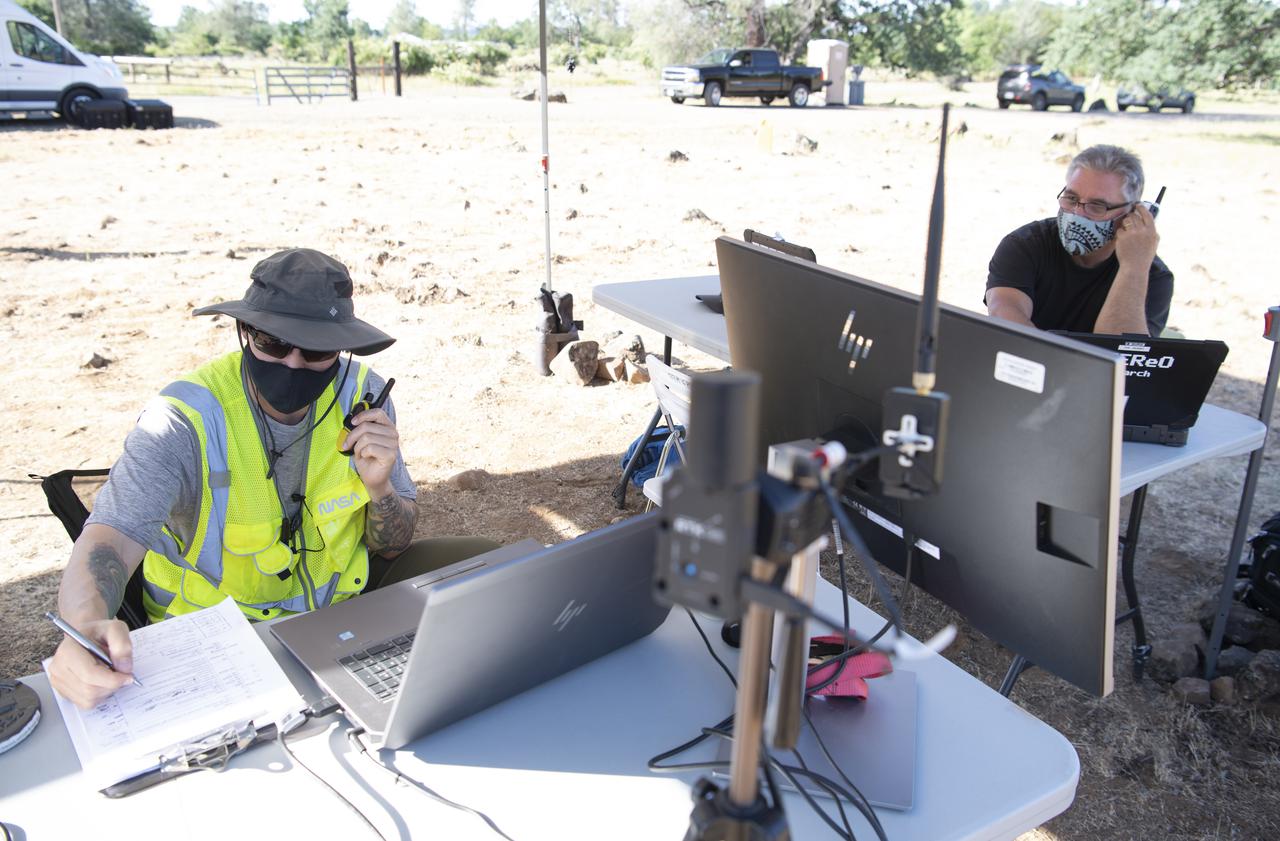
Zach Roberts, pilot computer operator for STEReO, the Scalable Traffic Management for Emergency Response Operations project, at NASA's Ames Research Center, right, Bill McCarthy, software engineer and research laptop operator for STEReO, at NASA's Ames Research Center, left, are seen during simulated drone operations as part of STEReO field testing, Wednesday, May 5, 2021 as Cal Fire conducts aerial fire fighting training exercises near Redding, California. STEReO, the Scalable Traffic Management for Emergency Response Operations project, led by NASA’s Ames Research Center, builds on NASA’s expertise in air traffic management, human factors research, and autonomous technology development to apply the agency’s work in Unmanned Aircraft Systems Traffic Management, or UTM, to public safety uses. Photo Credit: (NASA/Joel Kowsky)
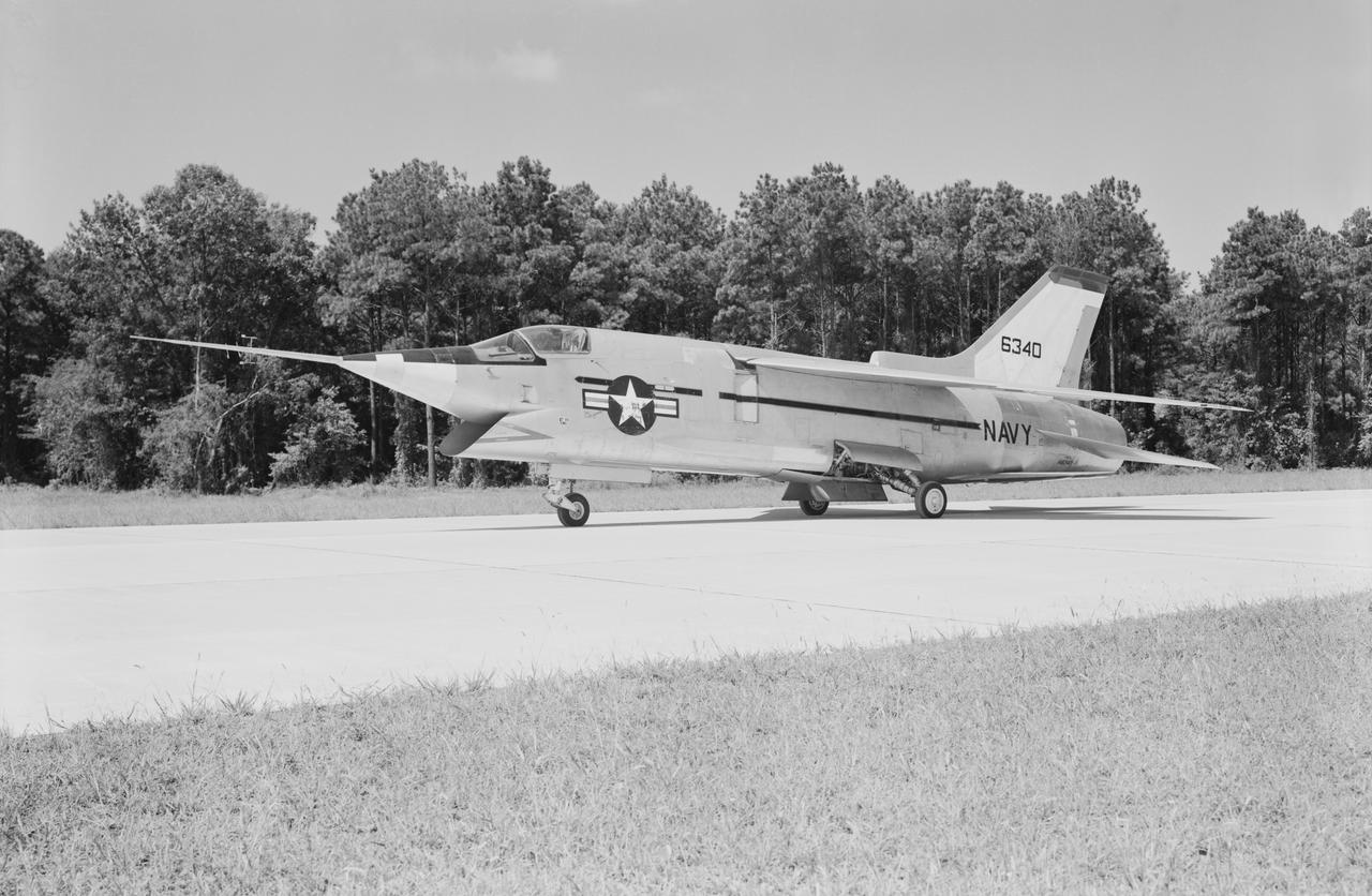
Crusader on runway. Navy aircraft number 6340. L59-6101 caption: The Navy's Vought XF8U-3 Supersonic Fighter was an entirely new design as compared to the earlier F8U Crusader series. This jet plane lost in competition with the McDonnell F4H, however, and was never put into production. Langley used the XF8U-3 in some of the first flight measurements of sonic boom intensity. Photograph published in Engineer in Charge A History of the Langley Aeronautical Laboratory, 1917-1958 by James R. Hansen. Page 507. Caption: Chance Vought F8U-3 airplane used in sonic boom investigation at Wallops, June-August 1959. Photograph published in A New Dimension Wallops Island Flight Test Range: The First Fifteen Years by Joseph Shortal. A NASA publication. Page 672.
Publicity photograph of a technician measuring a wind tunnel model of the Little Joe test vehicle. Joseph Shortal noted that (vol. 3, p. 29): The largest project at Wallops in support of Mercury was the Little Joe project, designed to qualify the abort-escape system under flight conditions. James Hansen (p. 47) writes: STG engineers Max Faget and Paul Purser, then of Langley's PARD, had conceived Little Joe as a space capsule test vehicle even before the establishment of NASA and the formation of the STG. Girlruth understood the importance of the Little Joe tests: We had to be sure there were no serious performance and operational problems that we had simply not thought of in such a new and radical type of flight vehicle. -- Published in James R. Hansen, Spaceflight Revolution: NASA Langley Research Center From Sputnik to Apollo, (Washington: NASA, 1995), p. 47 Joseph A. Shortal, History of Wallops Station: Origins and Activities Through 1949, (Wallops Island, VA: National Aeronautics and Space Administration, Wallops Station, nd), Comment Edition.

CAPE CANAVERAL, Fla. – NASA and contractor engineers are on hand at the Firing Room 4 Integration Console as operations to power down space shuttle Endeavour for the final time are under way in Orbiter Processing Facility-2 at NASA’s Kennedy Space Center in Florida. Standing, from left, are John Apfelbaum, Jeff Wheeler, Bob Walker and Michael Ciannilli of NASA. Seated, from left, are former United Space Alliance test project engineer Greg Koch, Debbie Awtonomow of NASA, and John McClellan of United Space Alliance. The Integration Console manages all orbiter systems including those needed for shuttle power up and launch. Endeavour is being prepared for public display at the California Science Center in Los Angeles. Its ferry flight to California is targeted for mid-September. Endeavour was the last space shuttle added to NASA’s orbiter fleet. Over the course of its 19-year career, Endeavour spent 299 days in space during 25 missions. For more information, visit http://www.nasa.gov/transition. Photo credit: NASA/Tim Jacobs
An engineer in the clean room at Lockheed Martin Space in Littleton, Colorado, affixes a dime-size chip onto the lander deck of NASA's InSight spacecraft. This second microchip, contains 1.6 million names submitted by the public to ride along with InSight to Mars. The chip was installed on Jan. 23, 2018. This joins another microchip that was previously installed that included 800,000 names for a grand total of 2.4 million names going to Mars as early as May 5, 2018. Engineers at NASA's Jet Propulsion Laboratory, Pasadena, California, put the names onto this tiny 0.3 square inches (8 millimeter-square) silicon wafer microchip using an electron beam to write extremely tiny letters with lines smaller than one one-thousandth the width of a human hair. The dime-size chip is affixed to the InSight lander deck and will remain on Mars forever. Normally used to make high-precision nanometer-scale devices, this technique was also used to write millions of names that were transported on NASA Mars rovers and Orion's first test flight. InSight is the first Mars mission dedicated to study the deep interior of Mars. Its findings will advance understanding of the early history of all rocky planets, including Earth. https://photojournal.jpl.nasa.gov/catalog/PIA22236
CAPE CANAVERAL, Fla. – NASA and contractor engineers are on hand at the Firing Room 4 Integration Console as operations to power down space shuttle Endeavour for the final time are under way in Orbiter Processing Facility-2 at NASA’s Kennedy Space Center in Florida. Standing, from left, are John Apfelbaum, Jeff Wheeler, Bob Walker and Michael Ciannilli of NASA. Seated is former United Space Alliance test project engineer Greg Koch. The Integration Console manages all orbiter systems including those needed for shuttle power up and launch. Endeavour is being prepared for public display at the California Science Center in Los Angeles. Its ferry flight to California is targeted for mid-September. Endeavour was the last space shuttle added to NASA’s orbiter fleet. Over the course of its 19-year career, Endeavour spent 299 days in space during 25 missions. For more information, visit http://www.nasa.gov/transition. Photo credit: NASA/Tim Jacobs
A Lockheed F-94B Starfire being equipped with an audio recording machine and sensors at the National Advisory Committee for Aeronautics (NACA) Lewis Flight Propulsion Laboratory. The NACA was investigating the acoustic effects caused by the engine’s nozzle and the air flowing along the fuselage. Airline manufacturers would soon be introducing jet engines on their passenger aircraft, and there was concern regarding the noise levels for both the passengers and public on the ground. NACA Lewis conducted a variety of noise reduction studies in its wind tunnels, laboratories, and on a F2H-2B Banshee aircraft. The F2H-2B Banshee’s initial test flights in 1955 and 1956 measured the noise emanating directly from airflow over the aircraft’s surfaces, particularly the wings. This problem was particularly pronounced at high subsonic speeds. The researchers found the majority of the noise occurred in the low and middle octaves. These investigations were enhanced with a series of flights using the F-94B Starfire. The missions measured wall-pressure, turbulence fluctuations, and mean velocity profiles. Mach 0.3 to 0.8 flights were flown at altitudes of 10,000, 20,000, and 30,000 feet with microphones mounted near the forward fuselage and on a wing. The results substantiated the wind tunnel findings. This photograph shows the tape recorder being installed in the F-94B’s nose.
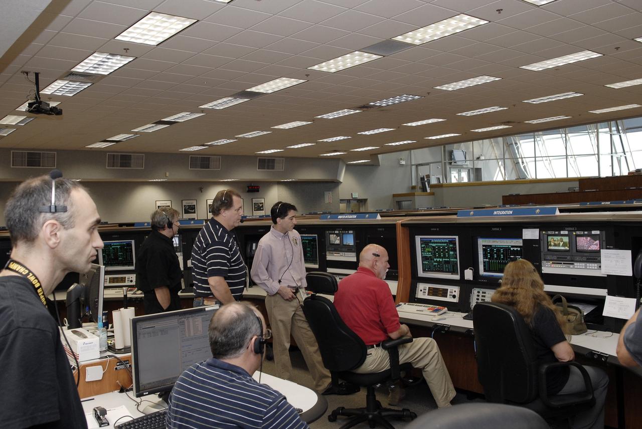
CAPE CANAVERAL, Fla. – NASA and contractor engineers are on hand at the Firing Room 4 Integration Console as operations to power down space shuttle Endeavour for the final time are under way in Orbiter Processing Facility-2 at NASA’s Kennedy Space Center in Florida. Standing, from left, are Alex Pandelos of QinetiQ North America and John Apfelbaum, Bob Walker and Michael Ciannilli of NASA. Seated, from left, are John McClellan and former test project engineer Greg Koch of United Space Alliance and Debbie Awtonomow of NASA. The Integration Console manages all orbiter systems including those needed for shuttle power up and launch. Endeavour is being prepared for public display at the California Science Center in Los Angeles. Its ferry flight to California is targeted for mid-September. Endeavour was the last space shuttle added to NASA’s orbiter fleet. Over the course of its 19-year career, Endeavour spent 299 days in space during 25 missions. For more information, visit http://www.nasa.gov/transition. Photo credit: NASA/Tim Jacobs
Men stand in front of turning vanes inside the Altitude Wind Tunnel (AWT) at the National Advisory Committee for Aeronautics (NACA) Aircraft Engine Research Laboratory. The AWT was the only wind tunnel capable of testing full-size aircraft engines in simulated altitude conditions. A large wooden drive fan, located on the other side of these vanes, created wind speeds up to 500 miles per hour. The drive shaft connected the fan to the induction motor located in an adjacent building. Turning vanes were located in each corner of the rectangular tunnel to straighten the airflow and direct it around the corners. This set of vanes was located in the 31-foot-diameter southeast corner of the tunnel. These elliptical panels consisted of 36 to 42 vertical vanes that were supported by three horizontal supports. The individual vanes were 2.5 feet long and half-moon shaped. The panel of vanes was affixed to the curved corner rings of the tunnel. Each set of turning vanes had a moveable vane in the middle of the lower level for personnel access. Each set of vanes took weeks to assemble before they were installed during the summer of 1943. This publicity photograph was taken just weeks after the tunnel became operational in February 1944.
NASA’s Ground Systems Development and Operations Program (GSDO) participates in a “Be Wise” program at the Reuben H. Fleet Science Center in San Diego, California. Participants listen to a presentation by engineers from the agency’s Kennedy Space Center in Florida. GSDO participated in several outreach events to students and the general public before the start of the Orion Underway Recovery Test 5 (URT-5) using a test version of the Orion crew module in the Pacific Ocean. URT-5 will allow NASA and the U.S. Navy to demonstrate and evaluate the recovery processes, procedures, hardware and personnel necessary for recovery of the Orion crew module on its return from a deep space mission. Orion is the exploration spacecraft designed to carry astronauts to destinations not yet explored by humans, including an asteroid and NASA’s Journey to Mars. It will have emergency abort capability, sustain the crew during space travel and provide safe re-entry from deep space return velocities. Orion is scheduled to launch atop NASA’s Space Launch System rocket in 2018. For more information, visit http://www.nasa.gov/orion.
NASA’s Ground Systems Development and Operations Program (GSDO) participates in a “Be Wise” program at the Reuben H. Fleet Science Center in San Diego, California. At the front table, from left are GSDO engineers Carla Koch and Janet Gobaira from the agency’s Kennedy Space Center in Florida. GSDO participated in several outreach events to students and the general public before the start of the Orion Underway Recovery Test 5 (URT-5) using a test version of the Orion crew module in the Pacific Ocean. URT-5 will allow NASA and the U.S. Navy to demonstrate and evaluate the recovery processes, procedures, hardware and personnel necessary for recovery of the Orion crew module on its return from a deep space mission. Orion is the exploration spacecraft designed to carry astronauts to destinations not yet explored by humans, including an asteroid and NASA’s Journey to Mars. It will have emergency abort capability, sustain the crew during space travel and provide safe re-entry from deep space return velocities. Orion is scheduled to launch atop NASA’s Space Launch System rocket in 2018. For more information, visit http://www.nasa.gov/orion.
NASA’s Ground Systems Development and Operations Program (GSDO) participates in a “Be Wise” program at the Reuben H. Fleet Science Center in San Diego, California. Participants listen to a presentation by engineers from the agency’s Kennedy Space Center in Florida. GSDO participated in several outreach events to students and the general public before the start of the Orion Underway Recovery Test 5 (URT-5) using a test version of the Orion crew module in the Pacific Ocean. URT-5 will allow NASA and the U.S. Navy to demonstrate and evaluate the recovery processes, procedures, hardware and personnel necessary for recovery of the Orion crew module on its return from a deep space mission. Orion is the exploration spacecraft designed to carry astronauts to destinations not yet explored by humans, including an asteroid and NASA’s Journey to Mars. It will have emergency abort capability, sustain the crew during space travel and provide safe re-entry from deep space return velocities. Orion is scheduled to launch atop NASA’s Space Launch System rocket in 2018. For more information, visit http://www.nasa.gov/orion.
NASA’s Ground Systems Development and Operations Program (GSDO) participates in a “Be Wise” program at the Reuben H. Fleet Science Center in San Diego, California. Carla Koch, left, and Janet Gobaira, engineers from Kennedy Space Center in Florida, talk with participants after the program. GSDO participated in several outreach events to students and the general public before the start of the Orion Underway Recovery Test 5 (URT-5) using a test version of the Orion crew module in the Pacific Ocean. URT-5 will allow NASA and the U.S. Navy to demonstrate and evaluate the recovery processes, procedures, hardware and personnel necessary for recovery of the Orion crew module on its return from a deep space mission. Orion is the exploration spacecraft designed to carry astronauts to destinations not yet explored by humans, including an asteroid and NASA’s Journey to Mars. It will have emergency abort capability, sustain the crew during space travel and provide safe re-entry from deep space return velocities. Orion is scheduled to launch atop NASA’s Space Launch System rocket in 2018. For more information, visit http://www.nasa.gov/orion.
KENNEDY SPACE CENTER, FLA. - The STS-114 crew gathers for media questions at the slidewire basket landing area on Launch Pad 39B. Monitored by NASA Public Affairs Officer George Diller (at left with microphone), members of the crew are, from left, Mission Specialists Andrew Thomas, Wendy Lawrence and Stephen Robinson, Commander Eileen Collins, Mission Specialists Charles Camarda and Soichi Noguchi, and Pilot James Kelly. Noguchi is with the Japan Aerospace Exploration Agency. The crew is at KSC for Terminal Countdown Demonstration Test (TCDT) activities. The TCDT is held at KSC prior to each Space Shuttle flight. It provides the crew of each mission an opportunity to participate in simulated countdown activities. The test ends with a mock launch countdown culminating in a simulated main engine cutoff. The crew also spends time undergoing emergency egress training exercises at the launch pad. STS-114 is designated the first Return to Flight mission, with a launch window extending from July 13 to July 31.
NASA’s Ground Systems Development and Operations Program (GSDO) participates in a “Be Wise” program at the Reuben H. Fleet Science Center in San Diego, California. At the front table, from left are GSDO engineers Carla Koch and Janet Gobaira from the agency’s Kennedy Space Center in Florida. GSDO participated in several outreach events to students and the general public before the start of the Orion Underway Recovery Test 5 (URT-5) using a test version of the Orion crew module in the Pacific Ocean. URT-5 will allow NASA and the U.S. Navy to demonstrate and evaluate the recovery processes, procedures, hardware and personnel necessary for recovery of the Orion crew module on its return from a deep space mission. Orion is the exploration spacecraft designed to carry astronauts to destinations not yet explored by humans, including an asteroid and NASA’s Journey to Mars. It will have emergency abort capability, sustain the crew during space travel and provide safe re-entry from deep space return velocities. Orion is scheduled to launch atop NASA’s Space Launch System rocket in 2018. For more information, visit http://www.nasa.gov/orion.
NASA’s Ground Systems Development and Operations Program (GSDO) participate in a “Be Wise” program at the Reuben H. Fleet Science Center in San Diego, California. At the front table, from left are GSDO engineers Carla Koch and Janet Gobaira from the agency’s Kennedy Space Center in Florida. GSDO participated in several outreach events to students and the general public before the start of the Orion Underway Recovery Test 5 (URT-5) using a test version of the Orion crew module in the Pacific Ocean. URT-5 will allow NASA and the U.S. Navy to demonstrate and evaluate the recovery processes, procedures, hardware and personnel necessary for recovery of the Orion crew module on its return from a deep space mission. Orion is the exploration spacecraft designed to carry astronauts to destinations not yet explored by humans, including an asteroid and NASA’s Journey to Mars. It will have emergency abort capability, sustain the crew during space travel and provide safe re-entry from deep space return velocities. Orion is scheduled to launch atop NASA’s Space Launch System rocket in 2018. For more information, visit http://www.nasa.gov/orion.
NASA’s Ground Systems Development and Operations Program (GSDO) participates in a “Be Wise” program at the Reuben H. Fleet Science Center in San Diego, California. Carla Koch, right, GSDO engineer from the agency’s Kennedy Space Center in Florida, talks with a student after the program. GSDO participated in several outreach events to students and the general public before the start of the Orion Underway Recovery Test 5 (URT-5) using a test version of the Orion crew module in the Pacific Ocean. URT-5 will allow NASA and the U.S. Navy to demonstrate and evaluate the recovery processes, procedures, hardware and personnel necessary for recovery of the Orion crew module on its return from a deep space mission. Orion is the exploration spacecraft designed to carry astronauts to destinations not yet explored by humans, including an asteroid and NASA’s Journey to Mars. It will have emergency abort capability, sustain the crew during space travel and provide safe re-entry from deep space return velocities. Orion is scheduled to launch atop NASA’s Space Launch System rocket in 2018. For more information, visit http://www.nasa.gov/orion.
NASA’s Ground Systems Development and Operations Program (GSDO) participates in a “Be Wise” program at the Reuben H. Fleet Science Center in San Diego, California. From left, are GSDO engineers Janet Gobaira and Carla Koch from the agency’s Kennedy Space Center in Florida. GSDO participated in several outreach events to students and the general public before the start of the Orion Underway Recovery Test 5 (URT-5) using a test version of the Orion crew module in the Pacific Ocean. URT-5 will allow NASA and the U.S. Navy to demonstrate and evaluate the recovery processes, procedures, hardware and personnel necessary for recovery of the Orion crew module on its return from a deep space mission. Orion is the exploration spacecraft designed to carry astronauts to destinations not yet explored by humans, including an asteroid and NASA’s Journey to Mars. It will have emergency abort capability, sustain the crew during space travel and provide safe re-entry from deep space return velocities. Orion is scheduled to launch atop NASA’s Space Launch System rocket in 2018. For more information, visit http://www.nasa.gov/orion.
CAPE CANAVERAL, Fla. – NASA Administrator Charlie Bolden helps mark the T-6 months and counting to the launch of Orion on Exploration Flight Test-1, or EFT-1, during a visit to the Operations and Checkout Building high bay at NASA's Kennedy Space Center in Florida. To his right is Rachel Kraft, NASA Public Affairs Officer, and standing behind him is Cleon Lacefield, Lockheed Martin Orion Program manager. The crew module has been stacked on the service module in the Final Assembly and System Testing cell. EFT-1 will provide engineers with data about the heat shield's ability to protect Orion and its future crews from the 4,000-degree heat of reentry and an ocean splashdown following the spacecraft’s 20,000-mph reentry from space. Data gathered during the flight will inform decisions about design improvements on the heat shield and other Orion systems, and authenticate existing computer models and new approaches to space systems design and development. This process is critical to reducing overall risks and costs of future Orion missions. Orion is the exploration spacecraft designed to carry astronauts to destinations not yet explored by humans, including an asteroid and Mars. It will have emergency abort capability, sustain the crew during space travel and provide safe re-entry from deep space return velocities. The first unpiloted test flight of the Orion is scheduled to launch later this year atop a Delta IV rocket from Cape Canaveral Air Force Station in Florida to an altitude of 3,600 miles above the Earth's surface. The two-orbit, four-hour flight test will help engineers evaluate the systems critical to crew safety including the heat shield, parachute system and launch abort system. For more information, visit http://www.nasa.gov/orion. Photo credit: NASA/Kim Shiflett
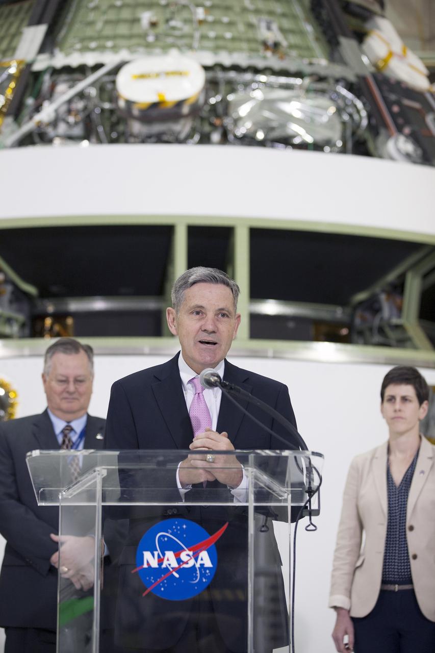
CAPE CANAVERAL, Fla. – Kennedy Space Center Director Bob Cabana helps mark the T-6 months and counting to the launch of Orion on Exploration Flight Test-1, or EFT-1, inside the Operations and Checkout Building high bay at Kennedy Space Center in Florida. To his right is Rachel Kraft, NASA Public Affairs Officer, and standing behind him is Cleon Lacefield, Lockheed Martin Orion Program manager. The crew module has been stacked on the service module in the Final Assembly and System Testing cell. EFT-1 will provide engineers with data about the heat shield's ability to protect Orion and its future crews from the 4,000-degree heat of reentry and an ocean splashdown following the spacecraft’s 20,000-mph reentry from space. Data gathered during the flight will inform decisions about design improvements on the heat shield and other Orion systems, and authenticate existing computer models and new approaches to space systems design and development. This process is critical to reducing overall risks and costs of future Orion missions. Orion is the exploration spacecraft designed to carry astronauts to destinations not yet explored by humans, including an asteroid and Mars. It will have emergency abort capability, sustain the crew during space travel and provide safe re-entry from deep space return velocities. The first unpiloted test flight of the Orion is scheduled to launch later this year atop a Delta IV rocket from Cape Canaveral Air Force Station in Florida to an altitude of 3,600 miles above the Earth's surface. The two-orbit, four-hour flight test will help engineers evaluate the systems critical to crew safety including the heat shield, parachute system and launch abort system. For more information, visit http://www.nasa.gov/orion. Photo credit: NASA/Kim Shiflett
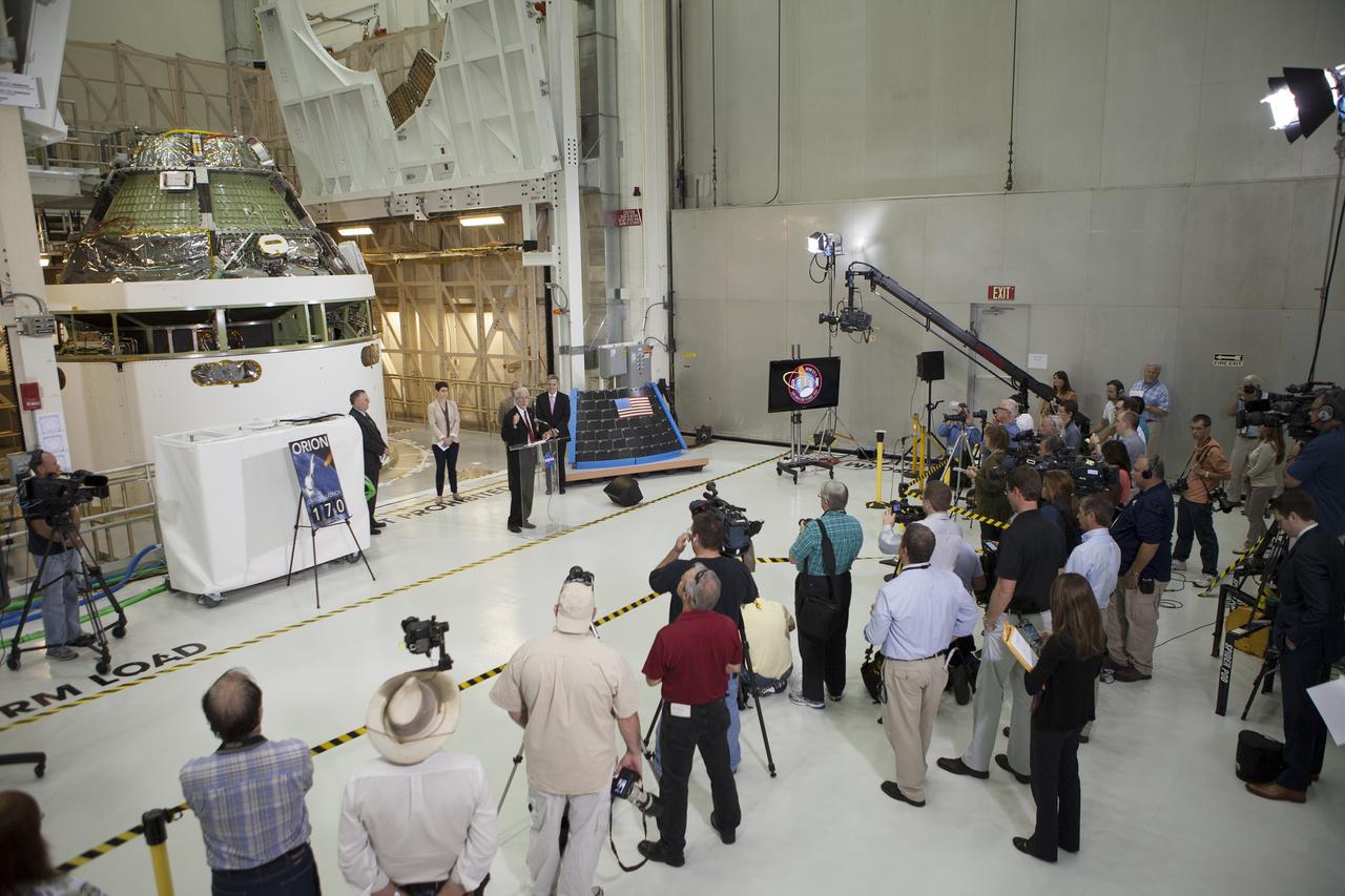
CAPE CANAVERAL, Fla. – Members of the media listen as NASA Orion Program Manager Mark Geyer marks the T-6 months and counting to the launch of Orion on Exploration Flight Test-1, or EFT-1, in the Operations and Checkout Building high bay at NASA's Kennedy Space Center in Florida. To his right is Kennedy Director Bob Cabana. Partially hidden behind him is NASA Administrator Charlie Bolden. To his left is Cleon Lacefield, Lockheed Martin Orion Program manager, and Rachel Kraft, NASA Public Affairs Officer. Behind them is the crew module stacked on the service module in the Final Assembly and System Testing cell. EFT-1 will provide engineers with data about the heat shield's ability to protect Orion and its future crews from the 4,000-degree heat of reentry and an ocean splashdown following the spacecraft’s 20,000-mph reentry from space. Data gathered during the flight will inform decisions about design improvements on the heat shield and other Orion systems, and authenticate existing computer models and new approaches to space systems design and development. This process is critical to reducing overall risks and costs of future Orion missions. Orion is the exploration spacecraft designed to carry astronauts to destinations not yet explored by humans, including an asteroid and Mars. It will have emergency abort capability, sustain the crew during space travel and provide safe re-entry from deep space return velocities. The first unpiloted test flight of the Orion is scheduled to launch later this year atop a Delta IV rocket from Cape Canaveral Air Force Station in Florida to an altitude of 3,600 miles above the Earth's surface. The two-orbit, four-hour flight test will help engineers evaluate the systems critical to crew safety including the heat shield, parachute system and launch abort system. For more information, visit http://www.nasa.gov/orion. Photo credit: NASA/Kim Shiflett
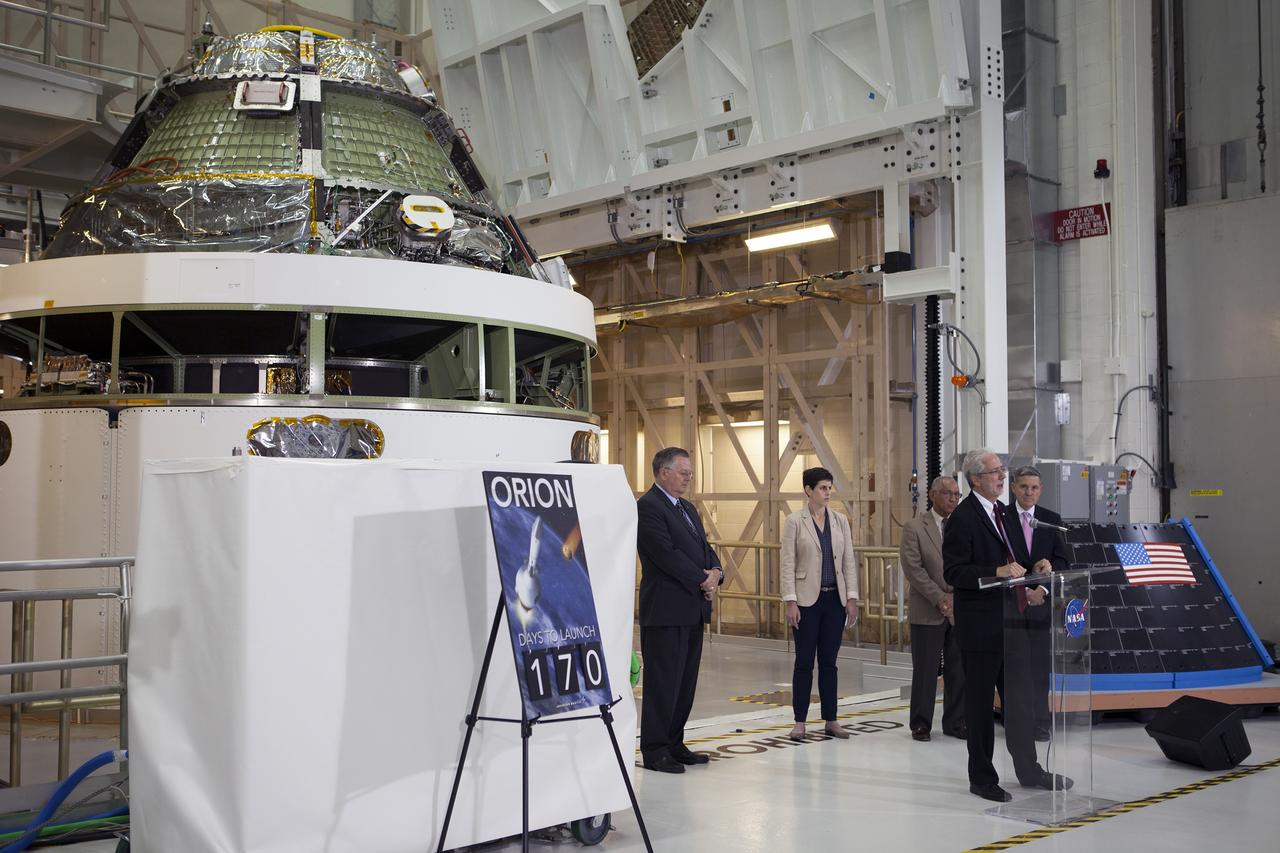
CAPE CANAVERAL, Fla. – Members of the media listen as NASA Orion Program Manager Mark Geyer marks the T-6 months and counting to the launch of Orion on Exploration Flight Test-1, or EFT-1, in the Operations and Checkout Building high bay at NASA's Kennedy Space Center in Florida. To his right is Kennedy Director Bob Cabana. Partially hidden behind him is NASA Administrator Charlie Bolden. To his left is Cleon Lacefield, Lockheed Martin Orion Program manager, and Rachel Kraft, NASA Public Affairs Officer. Behind them is the crew module stacked on the service module in the Final Assembly and System Testing cell. EFT-1 will provide engineers with data about the heat shield's ability to protect Orion and its future crews from the 4,000-degree heat of reentry and an ocean splashdown following the spacecraft’s 20,000-mph reentry from space. Data gathered during the flight will inform decisions about design improvements on the heat shield and other Orion systems, and authenticate existing computer models and new approaches to space systems design and development. This process is critical to reducing overall risks and costs of future Orion missions. Orion is the exploration spacecraft designed to carry astronauts to destinations not yet explored by humans, including an asteroid and Mars. It will have emergency abort capability, sustain the crew during space travel and provide safe re-entry from deep space return velocities. The first unpiloted test flight of the Orion is scheduled to launch later this year atop a Delta IV rocket from Cape Canaveral Air Force Station in Florida to an altitude of 3,600 miles above the Earth's surface. The two-orbit, four-hour flight test will help engineers evaluate the systems critical to crew safety including the heat shield, parachute system and launch abort system. For more information, visit http://www.nasa.gov/orion. Photo credit: NASA/Kim Shiflett
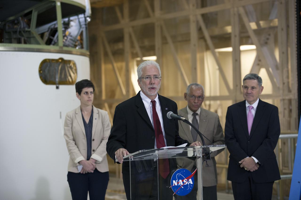
CAPE CANAVERAL, Fla. – Mark Geyer, NASA Orion Program manager, along with NASA Administrator Charlie Bolden, to his right, and Kennedy Space Center Director Bob Cabana help mark the T-6 months and counting to the launch of Orion on Exploration Flight Test-1, or EFT-1, inside the Operations and Checkout Building high bay at NASA's Kennedy Space Center in Florida. At left is Rachel Kraft, NASA Public Affairs Officer. The crew module has been stacked on the service module in the Final Assembly and System Testing cell. EFT-1 will provide engineers with data about the heat shield's ability to protect Orion and its future crews from the 4,000-degree heat of reentry and an ocean splashdown following the spacecraft’s 20,000-mph reentry from space. Data gathered during the flight will inform decisions about design improvements on the heat shield and other Orion systems, and authenticate existing computer models and new approaches to space systems design and development. This process is critical to reducing overall risks and costs of future Orion missions. Orion is the exploration spacecraft designed to carry astronauts to destinations not yet explored by humans, including an asteroid and Mars. It will have emergency abort capability, sustain the crew during space travel and provide safe re-entry from deep space return velocities. The first unpiloted test flight of the Orion is scheduled to launch later this year atop a Delta IV rocket from Cape Canaveral Air Force Station in Florida to an altitude of 3,600 miles above the Earth's surface. The two-orbit, four-hour flight test will help engineers evaluate the systems critical to crew safety including the heat shield, parachute system and launch abort system. For more information, visit http://www.nasa.gov/orion. Photo credit: NASA/Kim Shiflett
CAPE CANAVERAL, Fla. – NASA Public Affairs Officer Rachel Kraft welcomes members of the media to the Operations and Checkout Building high at NASA's Kennedy Space Center in Florida to mark the T-6 months and counting to the launch of Orion on Exploration Flight Test-1, or EFT-1. To her right are NASA Administrator Charlie Bolden and Kennedy Director Bob Cabana. To her left are Cleon Lacefield, Lockheed Martin Orion Program manager, and Mark Geyer, NASA Orion Program manager. Behind them is the crew module stacked on the service module in the Final Assembly and System Testing cell. EFT-1 will provide engineers with data about the heat shield's ability to protect Orion and its future crews from the 4,000-degree heat of reentry and an ocean splashdown following the spacecraft’s 20,000-mph reentry from space. Data gathered during the flight will inform decisions about design improvements on the heat shield and other Orion systems, and authenticate existing computer models and new approaches to space systems design and development. This process is critical to reducing overall risks and costs of future Orion missions. Orion is the exploration spacecraft designed to carry astronauts to destinations not yet explored by humans, including an asteroid and Mars. It will have emergency abort capability, sustain the crew during space travel and provide safe re-entry from deep space return velocities. The first unpiloted test flight of the Orion is scheduled to launch later this year atop a Delta IV rocket from Cape Canaveral Air Force Station in Florida to an altitude of 3,600 miles above the Earth's surface. The two-orbit, four-hour flight test will help engineers evaluate the systems critical to crew safety including the heat shield, parachute system and launch abort system. For more information, visit http://www.nasa.gov/orion. Photo credit: NASA/Kim Shiflett
SAN DIEGO, Calif. – NASA Administrator Charlie Bolden, center, talks to Milt Heflin on the USS Anchorage on the first day of Orion Underway Recovery Test 3. Heflin was a former space shuttle flight director and Mission Operations executive with experience as a recovery engineer for several Apollo, Skylab and Apollo-Soyuz Test Project missions. At left is Brandi Dean, NASA Public Affairs Office. The ship will head out to sea, off the coast of San Diego, in search of conditions to support test needs for a full dress rehearsal of recovery operations. NASA, Lockheed Martin and U.S. Navy personnel will conduct tests in the Pacific Ocean to prepare for recovery of the Orion crew module on its return from a deep space mission. The test will allow the teams to demonstrate and evaluate the recovery processes, procedures, hardware and personnel in open waters. The Ground Systems Development and Operations Program is conducting the underway recovery tests. Orion is the exploration spacecraft designed to carry astronauts to destinations not yet explored by humans, including an asteroid and Mars. It will have emergency abort capability, sustain the crew during space travel and provide safe re-entry from deep space return velocities. The first unpiloted test flight of Orion is scheduled to launch in 2014 atop a United Launch Alliance Delta IV Heavy rocket and in 2018 on NASA’s Space Launch System rocket. For more information, visit http://www.nasa.gov/orion. Photo credit: NASA/Cory Huston
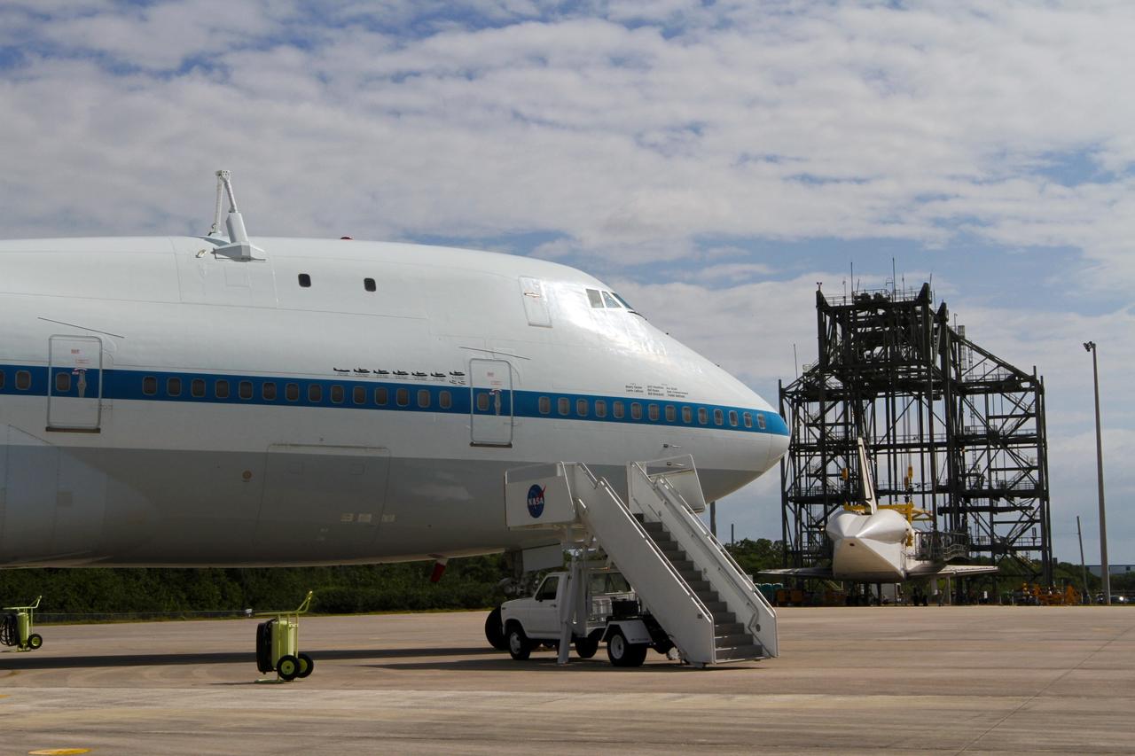
CAPE CANAVERAL, Fla. – At the Shuttle Landing Facility at NASA’s Kennedy Space Center in Florida, painted graphics line the side of NASA 905 depicting the various ferry flights the Shuttle Carrier Aircraft has supported during the Space Shuttle Program, including the tests using the space shuttle prototype Enterprise, and the names of the pilots and flight engineers who have flown it. Operations are under way at the mate-demate device, in the background, to lift Discovery on top of the aircraft. The device, known as the MDD, is a large gantry-like steel structure used to hoist a shuttle off the ground and position it onto the back of the aircraft, or SCA. The SCA is a Boeing 747 jet, originally manufactured for commercial use, which was modified by NASA to transport the shuttles between destinations on Earth. The SCA designated NASA 905 is assigned to the remaining ferry missions, delivering the shuttles to their permanent public display sites. NASA 905 is scheduled to ferry Discovery to the Washington Dulles International Airport in Virginia on April 17, after which the shuttle will be placed on display in the Smithsonian's National Air and Space Museum Steven F. Udvar-Hazy Center. For more information on the SCA, visit http://www.nasa.gov/centers/dryden/news/FactSheets/FS-013-DFRC.html. For more information on shuttle transition and retirement activities, visit http://www.nasa.gov/transition. Photo credit: NASA/Kim Shiflett

Members of the team known as Heatwave, from St. Petersburg, Fla., are excited after receiving an award at the FIRST (For Inspiration and Recognition of Science and Technology) Southeast Regional competition held at the KSC Visitor Complex. At left are Carol Cavanaugh, Public Affairs, and Nap Carroll, chief financial officer, Kennedy Space Center. Heatwave came in second for the final competition, plus received awards for Number One Seed, Best Offensive round, and the DaimlerChrysler Team Spirit. Teams of high school students from all over the country tested the limits of their imagination using robots they designed, with the support of business and engineering professionals and corporate sponsors, to compete in a technological battle against other schools' robots. Of the 30 high school teams competing at the Southeast Regional event, 16 were Florida teams co-sponsored by NASA and KSC contractors. Local high schools participating are Astronaut, Bayside, Cocoa Beach, Eau Gallie, Melbourne, Melbourne Central Catholic, Palm Bay, Rockledge, Satellite, and Titusville
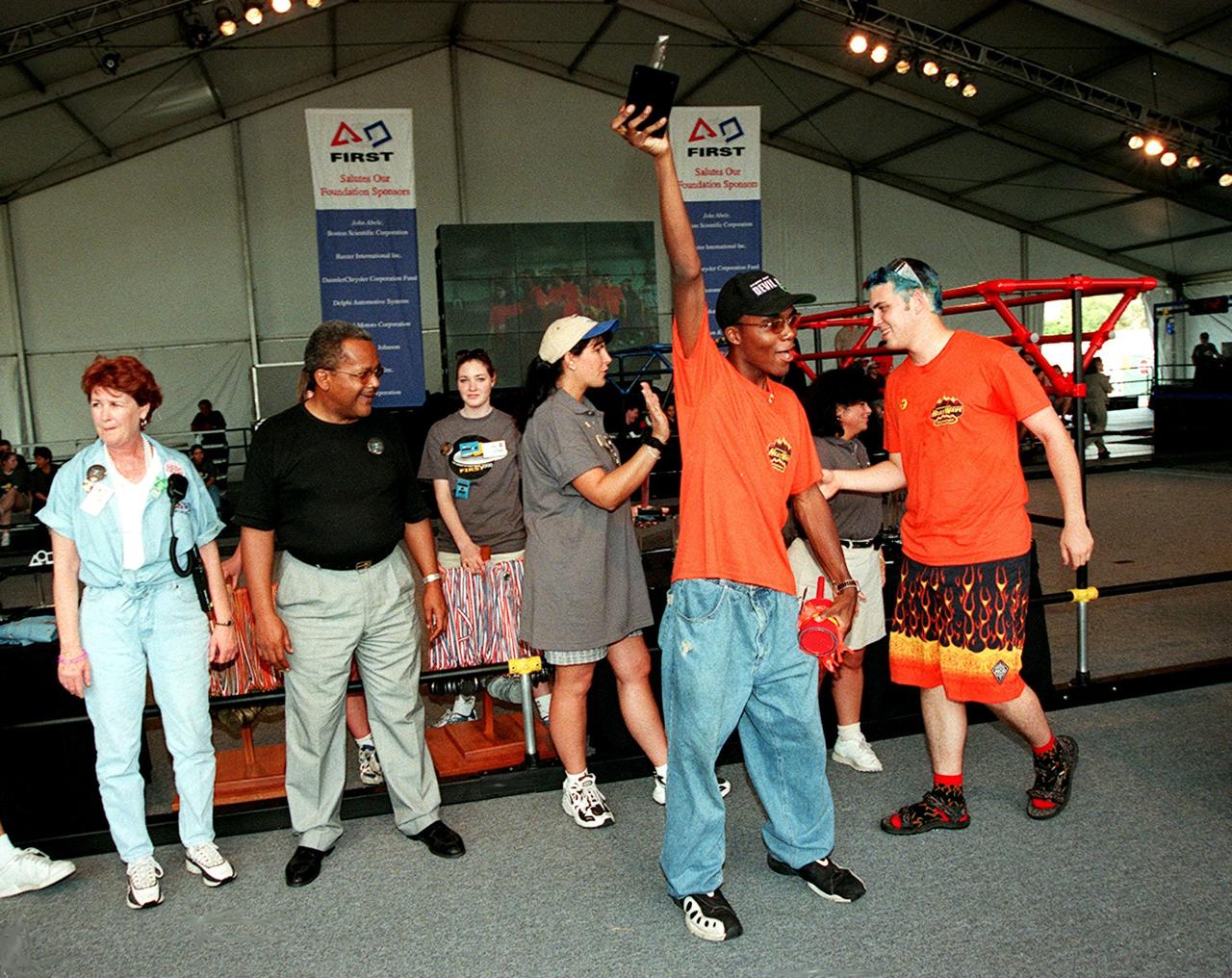
Members of the team known as Heatwave, from St. Petersburg, Fla., are excited after receiving an award at the FIRST (For Inspiration and Recognition of Science and Technology) Southeast Regional competition held at the KSC Visitor Complex. At left are Carol Cavanaugh, Public Affairs, and Nap Carroll, chief financial officer, Kennedy Space Center. Heatwave came in second for the final competition, plus received awards for Number One Seed, Best Offensive round, and the DaimlerChrysler Team Spirit. Teams of high school students from all over the country tested the limits of their imagination using robots they designed, with the support of business and engineering professionals and corporate sponsors, to compete in a technological battle against other schools' robots. Of the 30 high school teams competing at the Southeast Regional event, 16 were Florida teams co-sponsored by NASA and KSC contractors. Local high schools participating are Astronaut, Bayside, Cocoa Beach, Eau Gallie, Melbourne, Melbourne Central Catholic, Palm Bay, Rockledge, Satellite, and Titusville
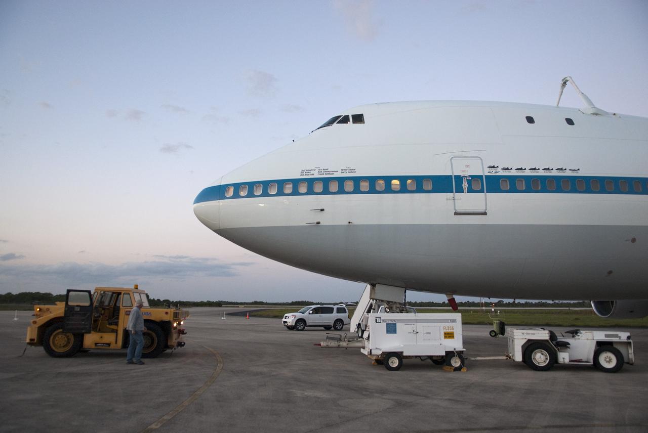
CAPE CANAVERAL, Fla. – At the Shuttle Landing Facility at NASA’s Kennedy Space Center in Florida, painted graphics line the side of NASA 905 depicting the various ferry flights the Shuttle Carrier Aircraft has supported during the Space Shuttle Program, including the tests using the space shuttle prototype Enterprise, and the names of the pilots and flight engineers who have flown it. This SCA, designated NASA 905, is a Boeing 747 jet originally manufactured for commercial use, which was modified by NASA to transport the shuttles between destinations on Earth. NASA 905 is assigned to the remaining ferry missions, delivering the shuttles to their permanent public display sites. Discovery’s new home will be the Smithsonian's National Air and Space Museum Steven F. Udvar-Hazy Center in Chantilly, Va. For more information on the SCA, visit http://www.nasa.gov/centers/dryden/news/FactSheets/FS-013-DFRC.html. For more information on shuttle transition and retirement activities, visit http://www.nasa.gov/transition. Photo credit: NASA/Tim Jacobs
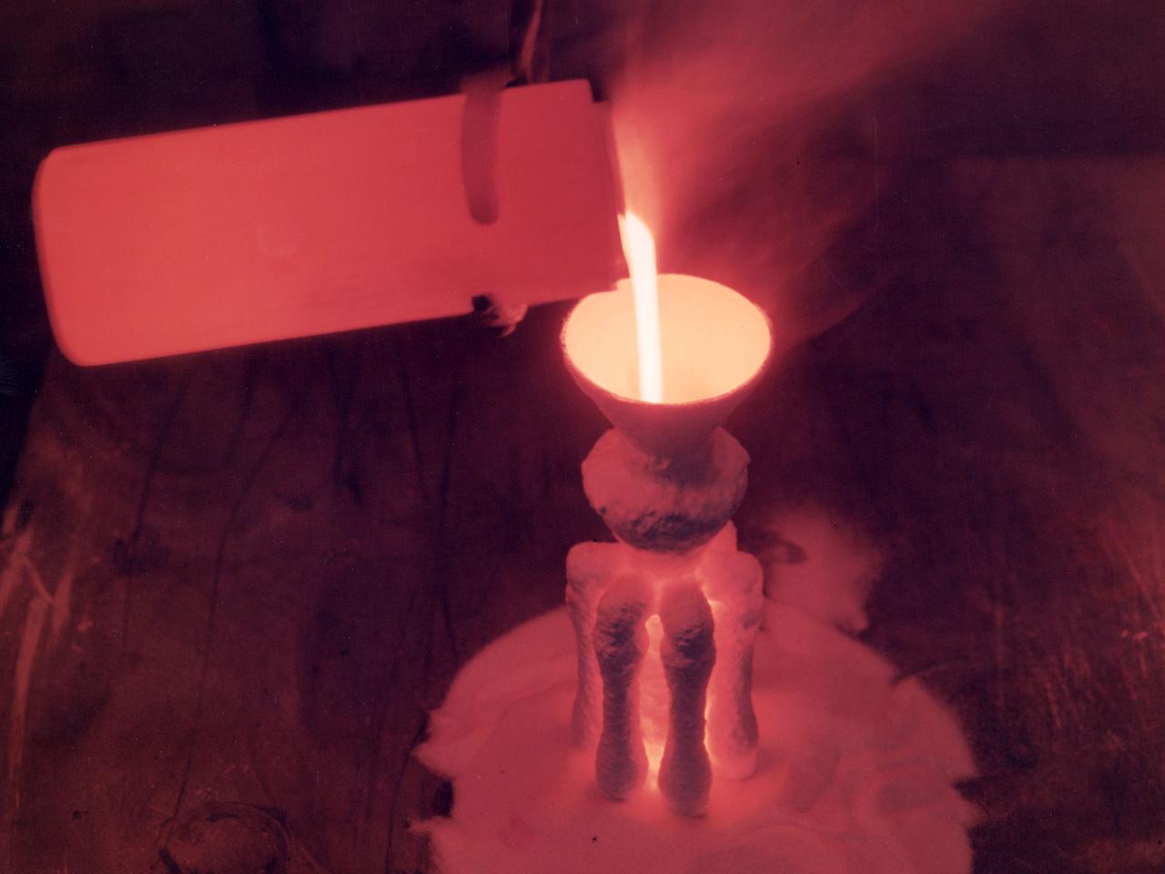
A nickel alloy developed at the National Aeronautics and Space Administration (NASA) Lewis Research Center being poured in a shop inside the Technical Services Building. Materials technology is an important element in the successful development of both advanced airbreathing and rocket propulsion systems. An array of dependable materials is needed to build different types of engines for operation in diverse environments. NASA Lewis began investigating the characteristics of different materials shortly after World War II. In 1949 the materials research group was expanded into its own division. The Lewis researchers studied and tested materials in environments that simulated the environment in which they would operate. Lewis created two programs in the early 1960s to create materials for new airbreathing engines. One concentrated on high-temperature alloys and the other on cooling turbine blades. William Klopp, Peter Raffo, Lester Rubenstein, and Walter Witzke developed Tungsten RHC, the highest strength metal at temperatures over 3500⁰ F. The men received an IR-100 Award for their efforts. Similarly a cobalt-tungsten alloy was developed by the Fatigue and Alloys Research Branch. The result was a combination of high temperature strength and magnetic properties that were applicable for generator rotor application. John Freche invented and patented a nickel alloy while searching for high temperature metals for aerospace use. NASA agreed to a three-year deal which granted Union Carbide exclusive use of the new alloy before it became public property.
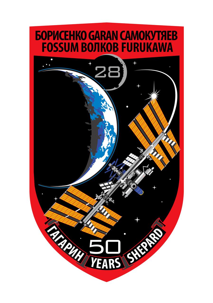
ISS028-S-001 (September 2010) --- In the foreground of the Expedition 28 patch, the International Space Station is prominently displayed to acknowledge the efforts of the entire International Space Station (ISS) team - both the crews who have assembled and operated it, and the team of scientists, engineers, and support personnel on Earth who have provided a foundation for each successful mission. Their efforts and accomplishments have demonstrated the Space Station?s capabilities as a technology test bed and a science laboratory, as well as a path to the human exploration of our solar system and beyond. This Expedition 28 patch represents the teamwork among the international partners ? USA, Russia, Japan, Canada, and the ESA - and the ongoing commitment from each partner to build, improve, and utilize the ISS. Prominently displayed in the background is our home planet, Earth - the focus of much of our exploration and research on our outpost in space. Also prominently displayed in the background is the Moon. The Moon is included in the design to stress the importance of our planet?s closest neighbor to the future of our world. Expedition 28 is scheduled to occur during the timeframe of the 50th anniversary of both the first human in space, Russian cosmonaut Yuri Gagarin and the first American in space, astronaut, Alan Shepard. To acknowledge the significant milestone of 50 years of human spaceflight, the names ????????? and ?Shepard? as well as ?50 Years? are included in the patch design. The NASA insignia design for shuttle and space station flights is reserved for use by the astronauts and for other official use as the NASA Administrator may authorize. Public availability has been approved only in the forms of illustrations by the various news media. When and if there is any change in this policy, which is not anticipated, the change will be publicly announced. Photo credit: NASA and its international partners.
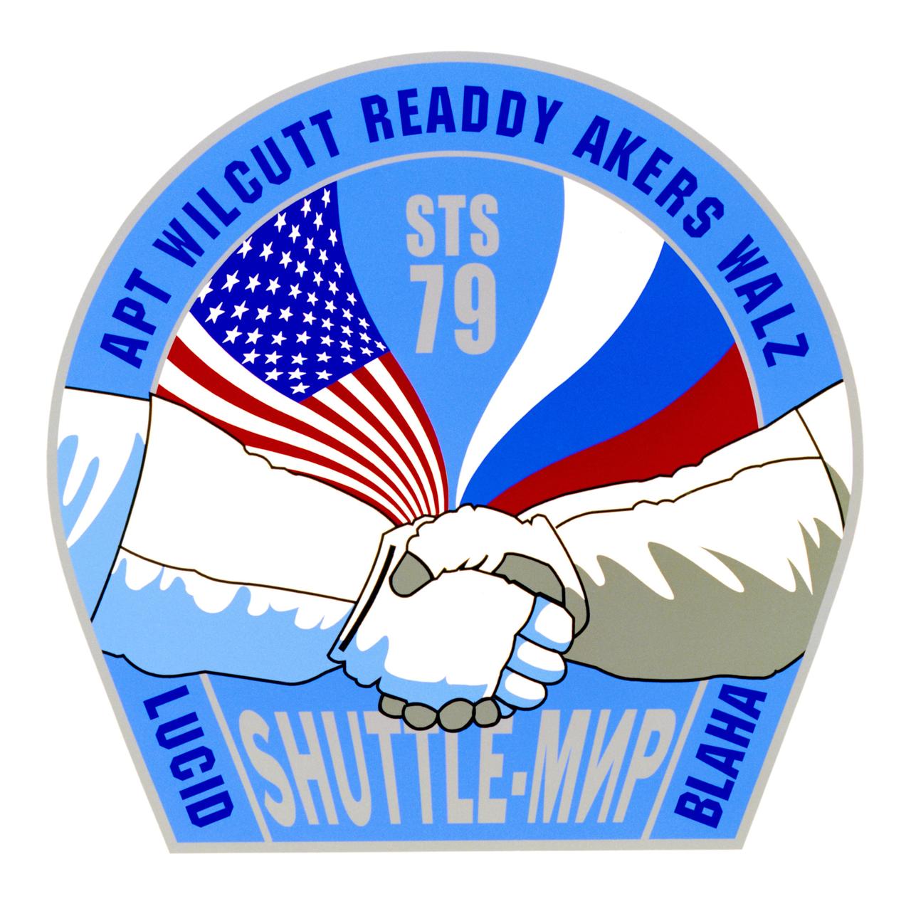
STS79-S-001 (April 1996) --- STS-79 is the fourth in a series of NASA docking missions to the Russian Mir Space Station, leading up to the construction and operation of the International Space Station (ISS). As the first flight of the Spacehab Double Module, STS-79 encompasses research, test and evaluation of ISS, as well as logistics resupply for the Mir Space Station. STS-79 is also the first NASA-Mir American crew member exchange mission, with John E. Blaha (NASA-Mir-3) replacing Shannon W. Lucid (NASA-Mir-2) aboard the Mir Space Station. The lettering of their names either up or down denotes transport up to the Mir Space Station or return to Earth on STS-79. The patch is in the shape of the space shuttle?s airlock hatch, symbolizing the gateway to international cooperation in space. The patch illustrates the historic cooperation between the United States and Russia in space. With the flags of Russia and the United States as a backdrop, the handshake of Extravehicular Mobility Unit (EMU) - suited crew members symbolizes mission teamwork, not only of the crew members but also the teamwork between both countries? space personnel in science, engineering, medicine and logistics. The NASA insignia design for space shuttle flights is reserved for use by the astronauts and for other official use as the NASA Administrator may authorize. Public availability has been approved only in the forms of illustrations by the various news media. When and if there is any change in this policy, which is not anticipated, the change will be publicly announced. Photo credit: NASA
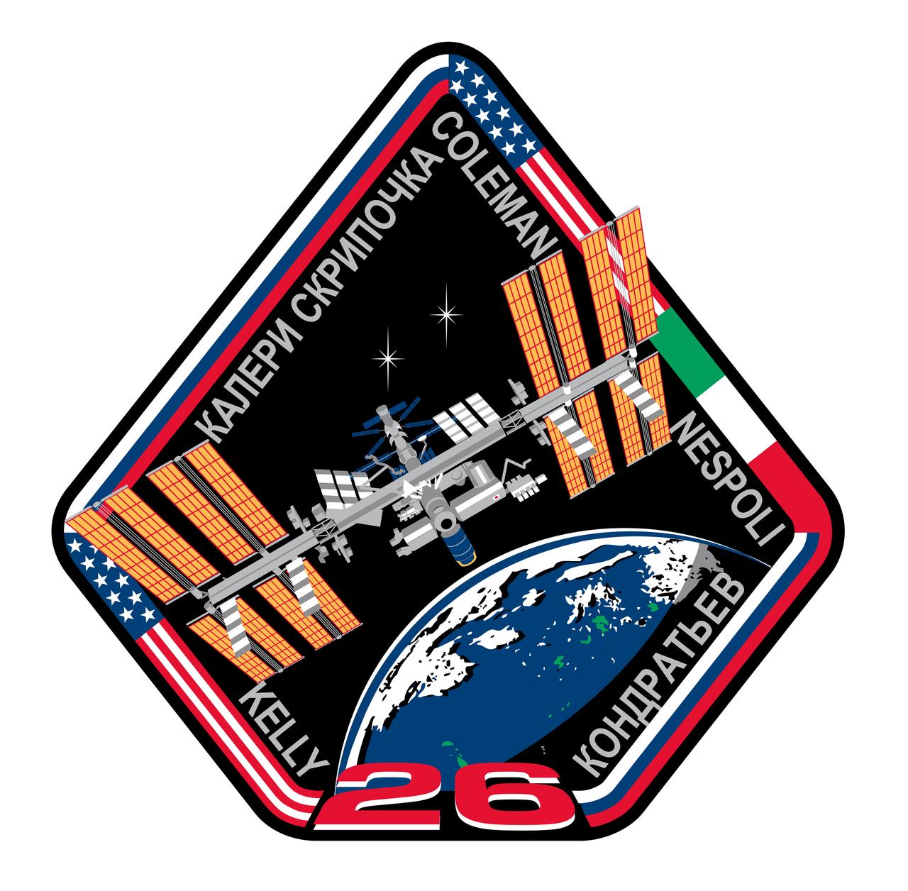
ISS026-S-001 (June 2010) --- In the foreground of the patch, the International Space Station is prominently displayed to acknowledge the efforts of the entire International Space Station (ISS) team - both the crews who have built and operated it, and the team of scientists, engineers, and support personnel on Earth who have provided a foundation for each successful mission. Their efforts and accomplishments have demonstrated the space station?s capabilities as a technology test bed and a science laboratory, as well as a path to the human exploration of our solar system and beyond. The ISS is shown with the European Space Agency?s (ESA) Automated Transfer Vehicle (ATV-2), the Johannes Kepler, docked to resupply it with experiments, food, water, and fuel for Expedition 26 and beyond. This Expedition 26 patch represents the teamwork among the international partners ? USA, Russia, Japan, Canada, and the ESA - and the ongoing commitment from each partner to build, improve, and utilize the ISS. Prominently displayed in the background is our home planet, Earth - the focus of much of our exploration and research on our outpost in space. The two stars symbolize two Soyuz spacecraft, each one carrying a three -member crew, who for four months will work and live together aboard the ISS as Expedition 26. The patch shows the crewmembers? names, and it?s framed with the flags of their countries of origin - United States, Russia, and Italy. The NASA insignia design for shuttle and space station flights is reserved for use by the astronauts and for other official use as the NASA Administrator may authorize. Public availability has been approved only in the form of illustrations by the various news media. When and if there is any change in this policy, which is not anticipated, it will be publicly announced.
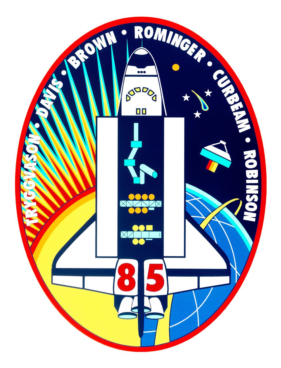
STS085-S-001 (May 1997) --- The mission patch for STS-85 is designed to reflect the broad range of science and engineering payloads on the flight. The primary objectives of the mission are to measure chemical constituents in Earth?s atmosphere with a free-flying satellite and to flight-test a new Japanese robotic arm designed for use on the International Space Station (ISS). STS-85 is the second flight of the satellite known as CRISTA-SPAS-02. CRISTA, depicted on the right side of the patch pointing its trio of infrared telescopes at Earth?s atmosphere, stands for Cryogenic Infrared Spectrometers and Telescopes for the Atmosphere. The high inclination orbit is shown as a yellow band over Earth?s northern latitudes. In the space shuttle Discovery?s open payload bay an enlarged version of the Japanese National Space Development Agency?s (NASDA) Manipulator Flight Demonstration (MFD) robotic arm is shown. Also shown in the payload bay are two sets of multi-science experiments: the International Extreme Ultraviolet Hitchhiker (IEH-02) nearest the tail and the Technology Applications and Science (TAS-01) payload. Jupiter and three stars are shown to represent sources of ultraviolet energy in the universe. Comet Hale-Bopp, which will be visible from Earth during the mission, is depicted at upper right. The left side of the patch symbolizes daytime operations over the Northern Hemisphere of Earth and the solar science objectives of several of the payloads. The NASA insignia design for space shuttle flights is reserved for use by the astronauts and for other official use as the NASA Administrator may authorize. Public availability has been approved only in the forms of illustrations by the various news media. When and if there is any change in this policy, which is not anticipated, the change will be publicly announced. Photo credit: NASA

Photographs documenting International Space Station (ISS) Phase One activities at the Russian Space Agency's (RSA) Gagarin Cosmonaut Training Center, Korolov Mission Control Center and Zvezda; and ISS and Soyuz manufacturing at RSA's Khrunichev Design Center and RSC Energiya in Moscow, Russia, the French Space Agency's (CNES) INTESPACE facility in Toulouse, France, and the Italian Space Agency's (ASI) Alenia Spazio facility in Torino, Italy. Photographs were taken by Johnson Space Center Imagery and Publications Office contractors travelling from October 7 to November 4, 1996. Includes: VIEWS FROM RSC ENERGIYA'S SPACE MUSEUM: Room with a Buran model and photographic displays (17372-374). Salyut Space Station mock-up (17376). Russian propulsion engines on display (17377-378). Russian spacecraft on display (17375, 17387-398). Graphic displays (17399-405). VIEWS FROM RSC ENERGIYA MANUFACTURING FACILITIES: Unidentified facility (17379). Mir 24 crew member Michael C. Foale, suited in a Soyuz pressure suit, ingresses the Soyuz TM-26 flight article at RSC Energiya for a fit check (17380-381). Closeups of Foale inside the Soyuz during the fit check (17382-383, 17466-467). Overhead views of RSC Energiya's Building 444 manufacturing floor where docking modules and Soyuz TM spacecraft are built (17495-498). Technicians on the Building 444 manufacturing floor assembling probe and drogue docking modules (17499-500, 17504). Technicians assembling Soyuz spacecraft (17437-439). Views of other Soyuz spacecraft (17440-441). Androgynous Peripheral Docking System (APDS) mock-up (17501-503). Closeups of a control panel, possibly for the APDS mock-up (17519-528). VIEWS FROM ZVEZDA, RSA CONTRACTOR FOR SUIT DESIGN AND SOYUZ SEAT LINERS: Mir 24 crew member Foale dons a "penguin" flight suit for a fit check (17454-456). Zvezda personnel adjust Foale's Soyuz seat and seat liner (17442). Closeup of Foale, suited in a Soyuz pressure suit, sitting on a chair (17444). Zvezda personnel strap pressure-suited Foale into his Soyuz seat (17443, 17445, 17450). Views of Foale in his Soyuz seat during a pressurized pressure suit fit check (17451-453). Views looking into a vacuum chamber where Foale, wearing pressure suit, is strapped into his Soyuz seat (17466-467). Views of Zvezda personnel working at the vacuum chamber control station during the vacuum chamber suit test (17468-471). VIEWS FROM KHRUNICHEV DESIGN CENTER: Views of a green ISS Functional Cargo Block (FGB) test article on the manufacturing floor (17529, 17532-536, 17540-544). Views of an ISS Service Module (SM) test article on the manufacturing floor (17530-531, 17537, 17539). Closeup of the SM test article docking sphere (17538). Views of the FGB flight article on the manufacturing floor during systems tests (17545-548, 17550-567). Views of technicians conducting the FGB systems tests (17549, 17557). VIEWS FROM GAGARIN COSMONAUT TRAINING CENTER: NASA astronauts work out in the cosmonaut gym at Gagarin: Closeup of ISS 2R Expedition Commander William Shepherd on a weight machine (17384). Shepherd and an unidentified man with back to camera work out with dumbbells (17386). Shepherd does pull-ups (17447). Closeup of Foale on an exercise machine (17385). Closeups of Foale exercising arms on a cycle ergometer and a weight machine (17415, 17448-449). Foale exercises on a Nordic Track (17416). Closeup of Mir 23 crew member Jerry Linenger exercising arms (17417). Wendy Lawrence exercises with dumbbells (17418). Closeup of Lawrence in a handstand position (17419). David Wolf works out on a leg press machine (17446). Views of the Mir Space Station mock-up at Gagarin: Interior views of the Mir Base Module mock-up looking toward the transfer compartment (17421-425). Mir Base Module living area mock-up (17420). Overall views of the Base Module mock-up central control station (17426-427, 17505). Closeups of switch panels on the central control station (17428-436, 17506-518). Other views from Gagarin: Personnel work at an unidentified test/trainer control station (17472-473). Linenger sits at a table next to an RSA trainer during a Mir 23 meeting (17475-476). Out-of-focus view of two subjects in the Soyuz trainer (17474). Foale examines a Mir Complex EVA Suit (Orlan) with RSA trainers during an EVA suit training class (17492-494). VIEWS FROM KOROLOV MISSION CONTROL CENTER: Various views of personnel working in the NASA Consulting Room and/or PAO Consulting Room at Korolov Mission Control Center (17457-463). VIEWS FROM INTESPACE: Exterior views of an ISS Mini Pressurized Logistics Module (MPLM) structural test article (STA) during testing at INTESPACE (17406-409, 17477, 17482-484). Technicians install hatch on the MPLM STA (17410-414). Interior views of the MPLM STA (17478-481). VIEWS FROM ALENIA SPAZIO: Closeups of MPLM flight article #1 side panels during milling and refining at Alenia Spazio (17485-488). Workers process MPLM parts at milling machines (17489-491).