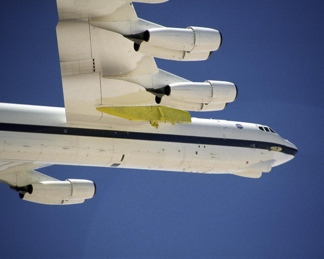
A newly constructed pylon (green) for carrying aerospace vehicles aloft flies attached to the wing of NASA Dryden Flight Research Center's B-52H aircraft.
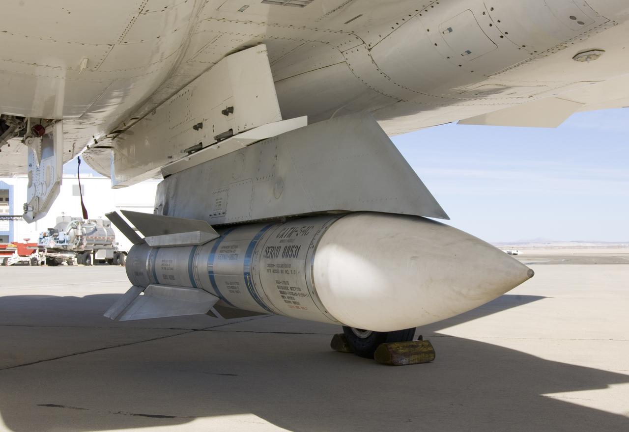
Surplus Navy Phoenix missiles like this one mounted on the centerline pylon of NASA's F-15B research aircraft may be used to acquire hypersonic flight test data.
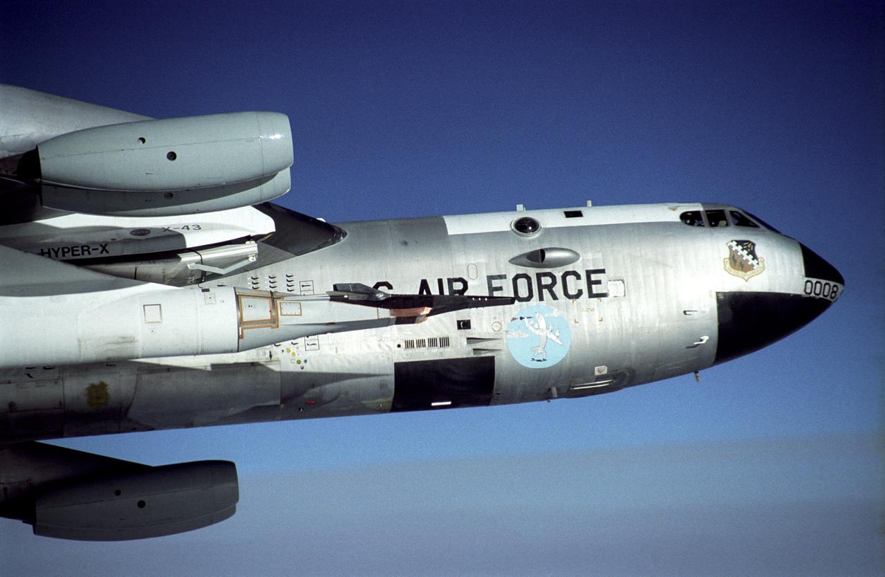
The black X-43A rides on the front of a modified Pegasus booster rocket hung from the special pylon under the wing of NASA's B-52B mother ship. The photo was taken during a captive carry flight Jan. 26, 2004 to verify systems before an upcoming launch.
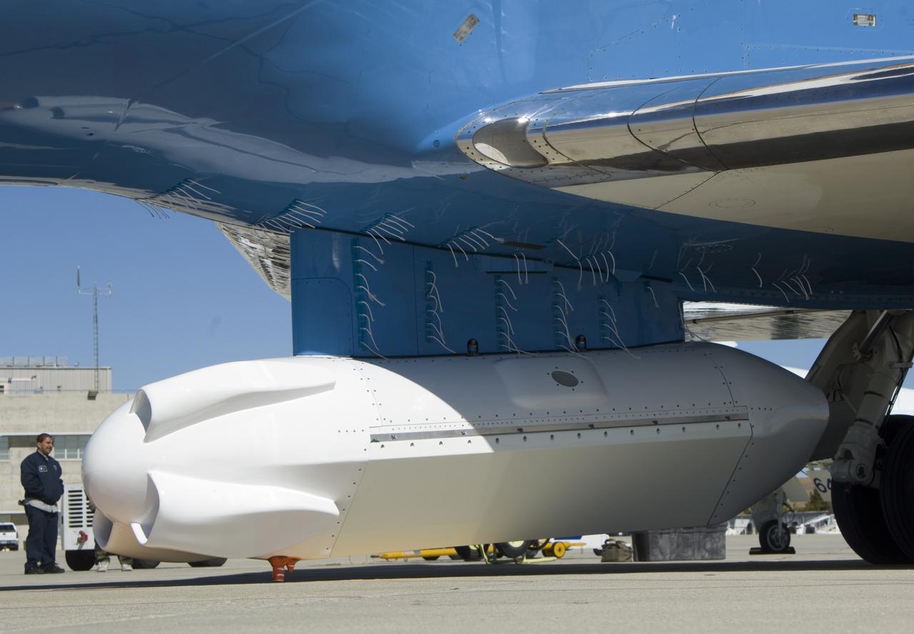
A forest of tufts are mounted on the underbelly and pylon of NASA's Gulfstream-III research aircraft to help engineers determine airflow around the UAVSAR pod.
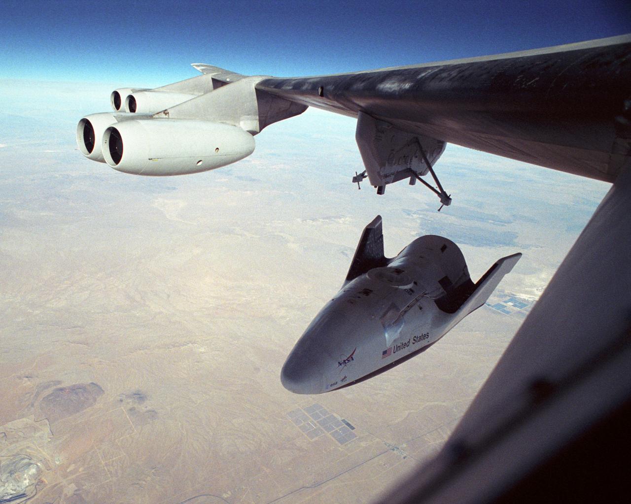
The X-38 prototype of the Crew Return Vehicle for the International Space Station drops away from its launch pylon on the wing of NASA's NB-52B mothership as it begins its eighth free flight on Thursday, Dec. 13, 2001. The 13-minute test flight of X-38 vehicle 131R was the longest and fastest and was launched from the highest altitude to date in the X-38's atmospheric flight test program. A portion of the descent was flown under remote control by a NASA astronaut from a ground vehicle configured like the CRV's interior before the X-38 made an autonomous landing on Rogers Dry Lake.
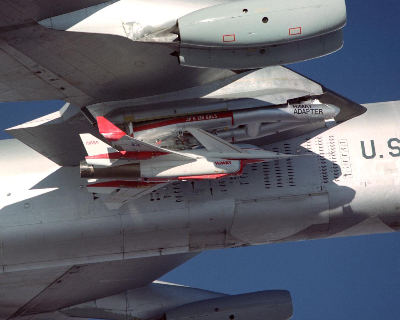
A close-up view of the Highly Maneuverable Aircraft Technology (HiMAT) research vehicle attached to a wing pylon on NASA’s B-52 mothership during a 1980 test flight. The HiMAT used sharply swept-back wings and a canard configuration to test possible technology for advanced fighters.
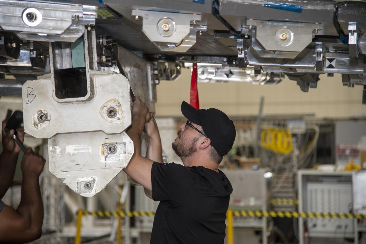
The outboard pylon load fixture is secured for the F/A-18E from the Naval Air Systems Command (NAVAIR) in Patuxent River, Maryland. The aircraft is in NASA’s Armstrong Flight Research Center Flight Loads Laboratory in Edwards, California, for the center’s biggest load calibrations tests. This testing is needed before the aircraft can serve as a test vehicle for determining if it can safely manage maneuvers and proposed upgrades.
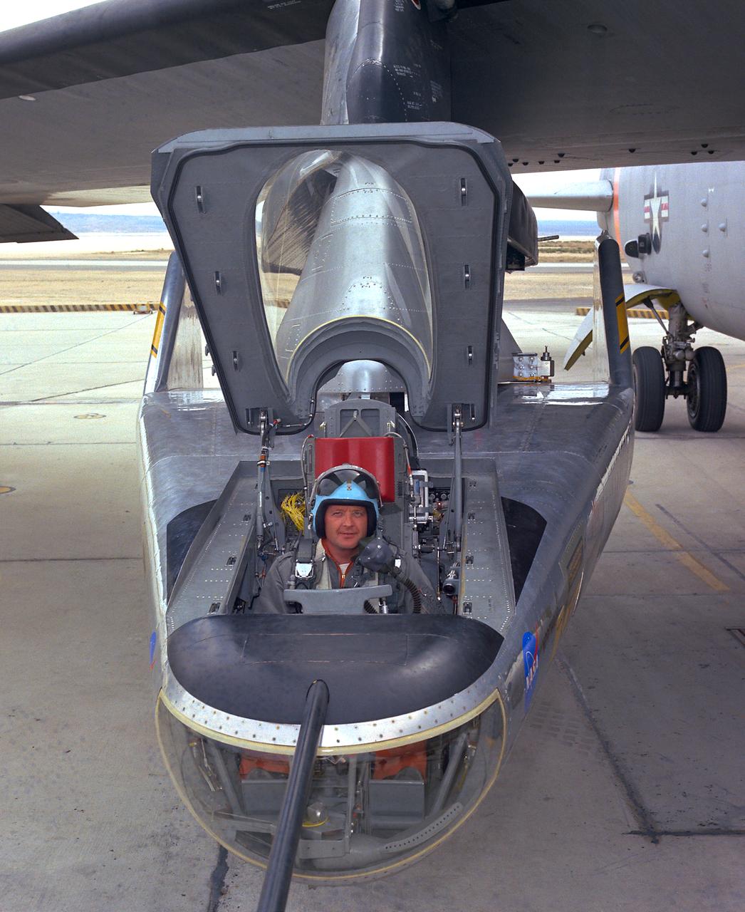
NASA research pilot Milt Thompson sits in the M2-F2 "heavyweight" lifting body research vehicle before a 1966 test flight. The M2-F2 and the other lifting-body designs were all attached to a wing pylon on NASA’s B-52 mothership and carried aloft. The vehicles were then drop-launched and, at the end of their flights, glided back to wheeled landings on the dry lake or runway at Edwards AFB. The lifting body designs influenced the design of the Space Shuttle and were also reincarnated in the design of the X-38 in the 1990s.
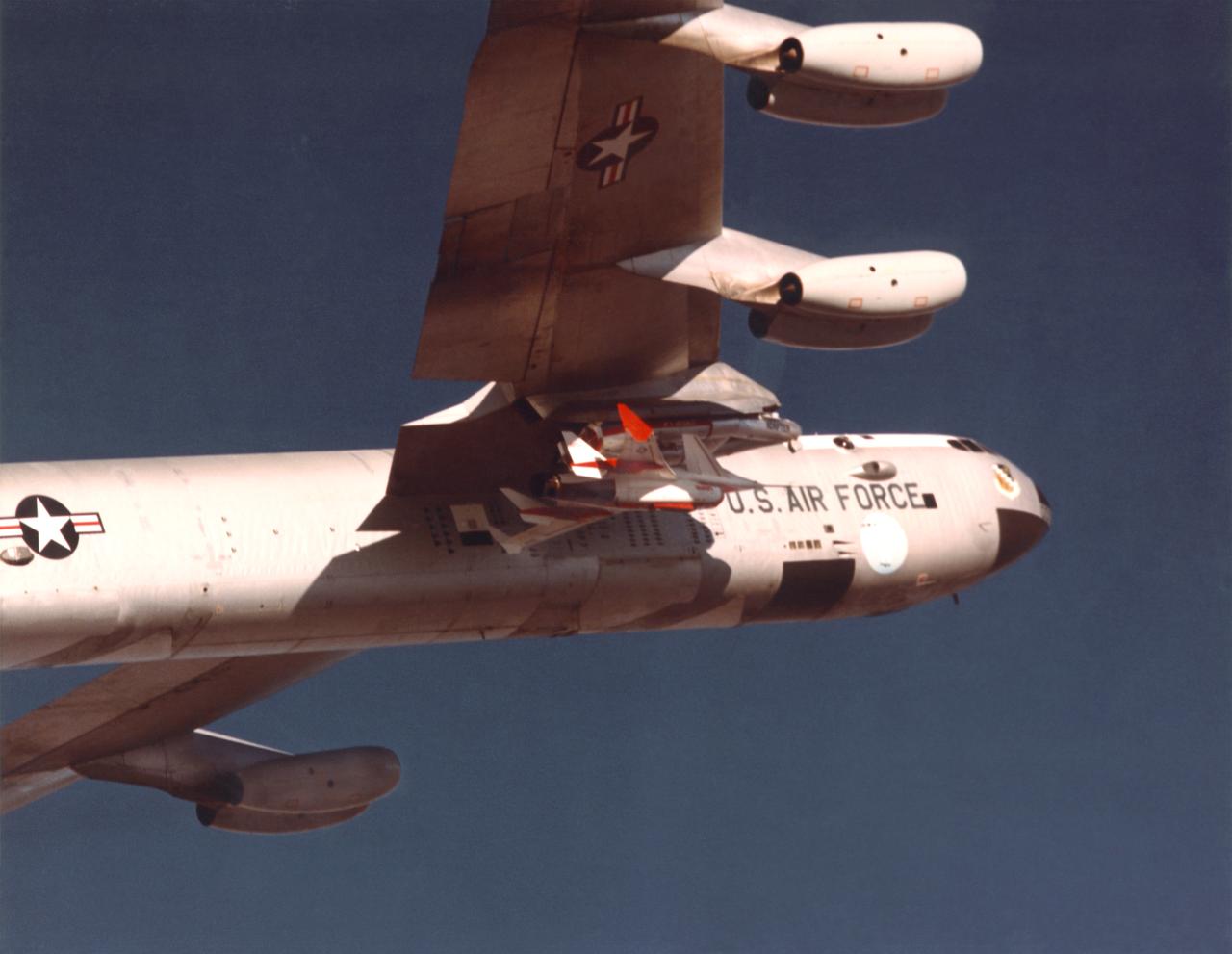
The Highly Maneuverable Aircraft Technology (HiMAT) research vehicle is shown here mated to a wing pylon on NASA’s B-52 mothership aircraft. The HiMAT was a technology demonstrator to test structures and configurations for advanced fighter concepts. Over the course of more than 40 years, the B-52 proved a valuable workhorse for NASA’s Dryden Flight Research Center (under various names), launching a wide variety of vehicles and conducting numerous other research flights.
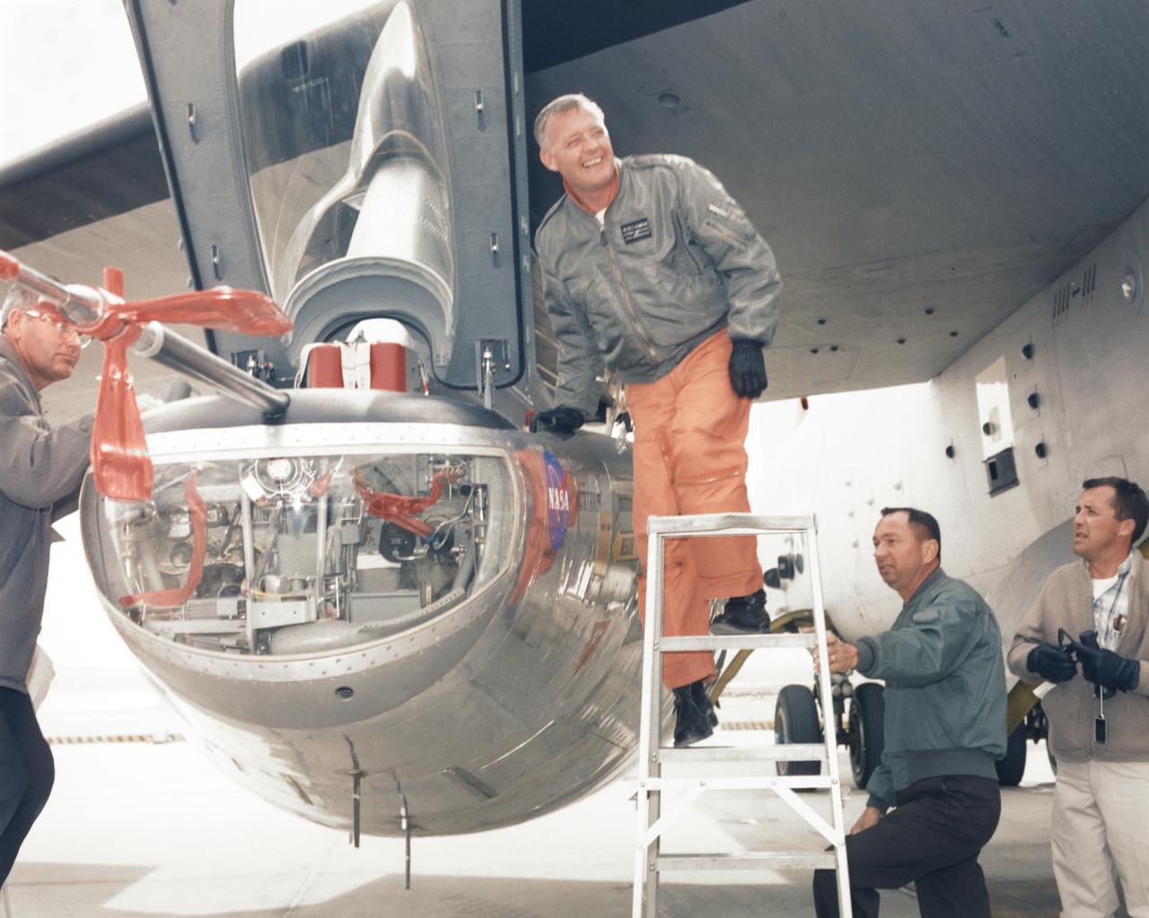
NASA research pilot Milt Thompson is helped into the cockpit of the M2-F2 lifting body research aircraft at NASA’s Flight Research Center (now the Dryden Flight Research Center). The M2-F2 is attached to a wing pylon under the wing of NASA’s B-52 mothership. The flight was a captive flight with the pilot on-board. Milt Thompson flew in the lifting body throughout the flight, but it was never dropped from the mothership.
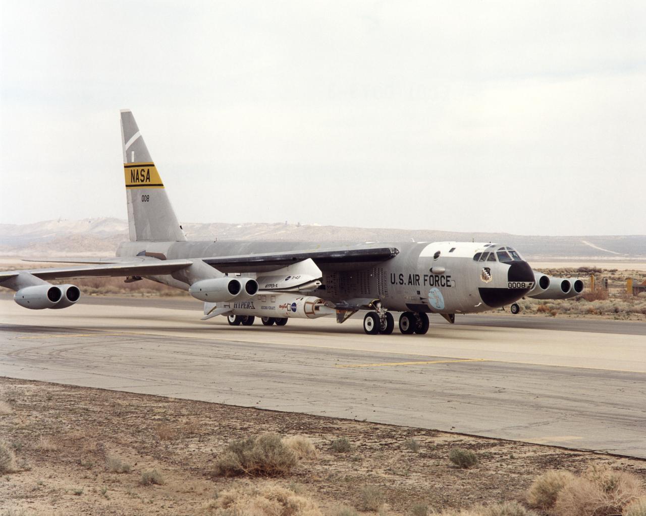
NASA's NB-52B carrier aircraft rolls down a taxiway at Edwards Air Force Base with the X-43A hypersonic research aircraft and its modified Pegasus® booster rocket slung from a pylon under its right wing. Part of a combined systems test conducted by NASA's Dryden Flight Research Center at Edwards, the taxi test was one of the last major milestones in the Hyper-X research program before the first X-43A flight. The X-43A flights will be the first actual flight tests of an aircraft powered by a revolutionary supersonic-combustion ramjet ("scramjet") engine capable of operating at hypersonic speeds (above Mach 5, or five times the speed of sound). The 12-foot, unpiloted research vehicle was developed and built by MicroCraft Inc., Tullahoma, Tenn., under NASA contract. The booster was built by Orbital Sciences Corp., Dulles, Va.,After being air-launched from NASA's venerable NB-52 mothership, the booster will accelerate the X-43A to test speed and altitude. The X-43A will then separate from the rocket and fly a pre-programmed trajectory, conducting aerodynamic and propulsion experiments until it descends into the Pacific Ocean. Three research flights are planned, two at Mach 7 and one at Mach 10, with the first tentatively scheduled for late spring to early summer, 2001.
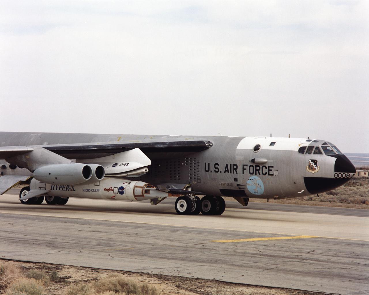
As part of a combined systems test conducted by NASA Dryden Flight Research Center, NASA's NB-52B carrier aircraft rolls down a taxiway at Edwards Air Force Base with the X-43A hypersonic research aircraft and its modified Pegasus® booster rocket attached to a pylon under its right wing. The taxi test was one of the last major milestones in the Hyper-X research program before the first X-43A flight. The X-43A flights will be the first actual flight tests of an aircraft powered by a revolutionary supersonic-combustion ramjet ("scramjet") engine capable of operating at hypersonic speeds (above Mach 5, or five times the speed of sound). The 12-foot, unpiloted research vehicle was developed and built by MicroCraft Inc., Tullahoma, Tenn., under NASA contract. The booster was built by Orbital Sciences Corp., Dulles, Va. After being air-launched from NASA's venerable NB-52 mothership, the booster will accelerate the X-43A to test speed and altitude. The X-43A will then separate from the rocket and fly a pre-programmed trajectory, conducting aerodynamic and propulsion experiments until it descends into the Pacific Ocean. Three research flights are planned, two at Mach 7 and one at Mach 10.
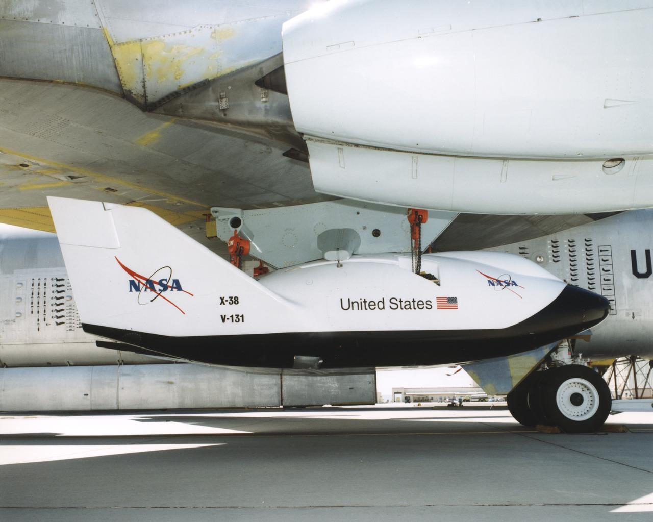
A close-up view of the X-38 research vehicle mounted under the wing of the B-52 mothership prior to a 1997 test flight. The X-38, which was designed to help develop technology for an emergency crew return vehicle (CRV) for the International Space Station, is one of many research vehicles the B-52 has carried aloft over the past 40 years.
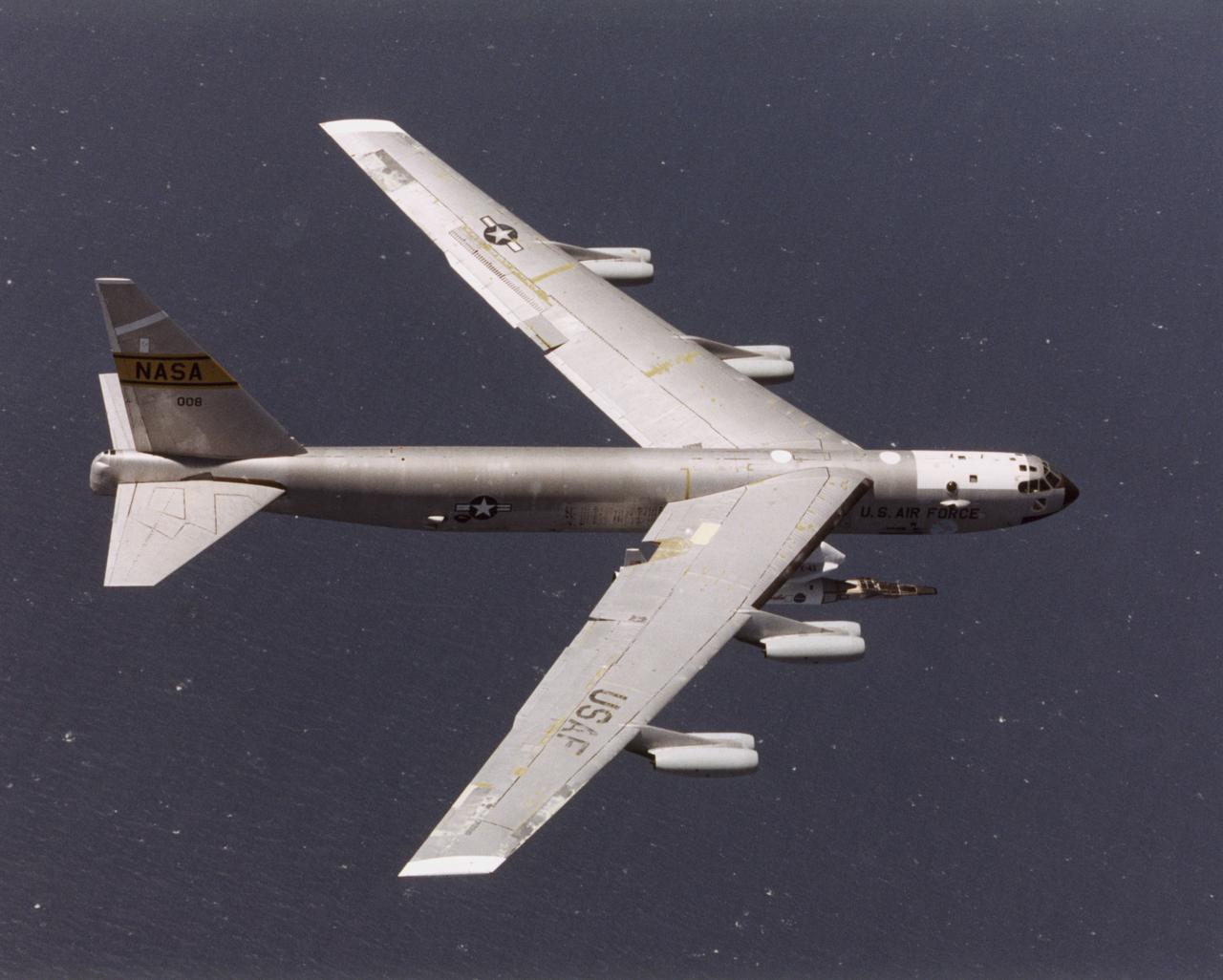
The NASA X-43A hypersonic research vehicle and its Pegasus booster rocket, mounted beneath the wing of their B-52 mothership, had a successful first captive-carry flight on April 28, 2001, Basically a dress rehearsal for a subsequent free flight, the captive-carry flight kept the X-43A-and-Pegasus combination attached to the B-52's wing pylon throughout the almost two-hour mission from NASA's Dryden Flight Research Center, Edwards, Calif., over the Pacific Missile Test Range, and back to Dryden.
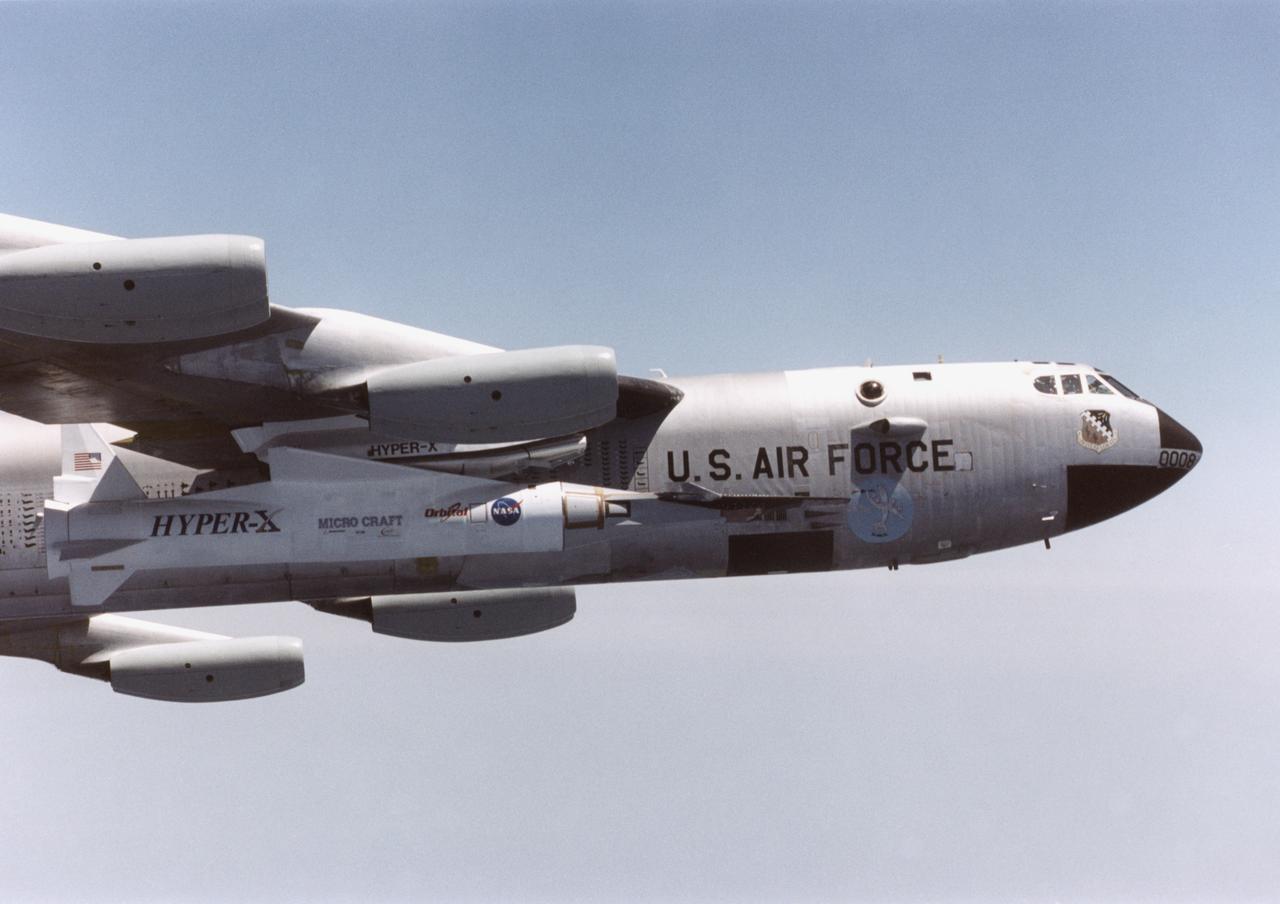
The NASA X-43A hypersonic research vehicle and its Pegasus booster rocket, mounted beneath the wing of their B-52 mothership, had a successful first captive-carry flight on April 28, 2001, Basically a dress rehearsal for a subsequent free flight, the captive-carry flight kept the X-43A-and-Pegasus combination attached to the B-52's wing pylon throughout the almost two-hour mission from NASA's Dryden Flight Research Center, Edwards, Calif., over the Pacific Missile Test Range, and back to Dryden.
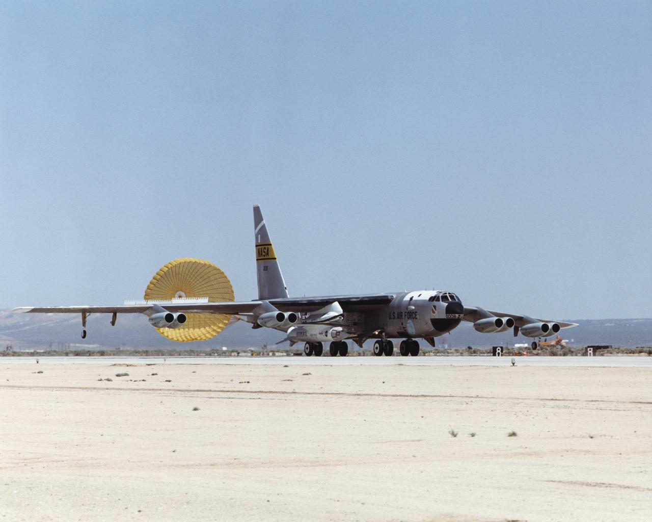
The NASA X-43A hypersonic research vehicle and its Pegasus booster rocket, mounted beneath the wing of their B-52 mothership, had a successful first captive-carry flight on April 28, 2001, Basically a dress rehearsal for a subsequent free flight, the captive-carry flight kept the X-43A-and-Pegasus combination attached to the B-52's wing pylon throughout the almost two-hour mission from NASA's Dryden Flight Research Center, Edwards, Calif., over the Pacific Missile Test Range, and back to Dryden.
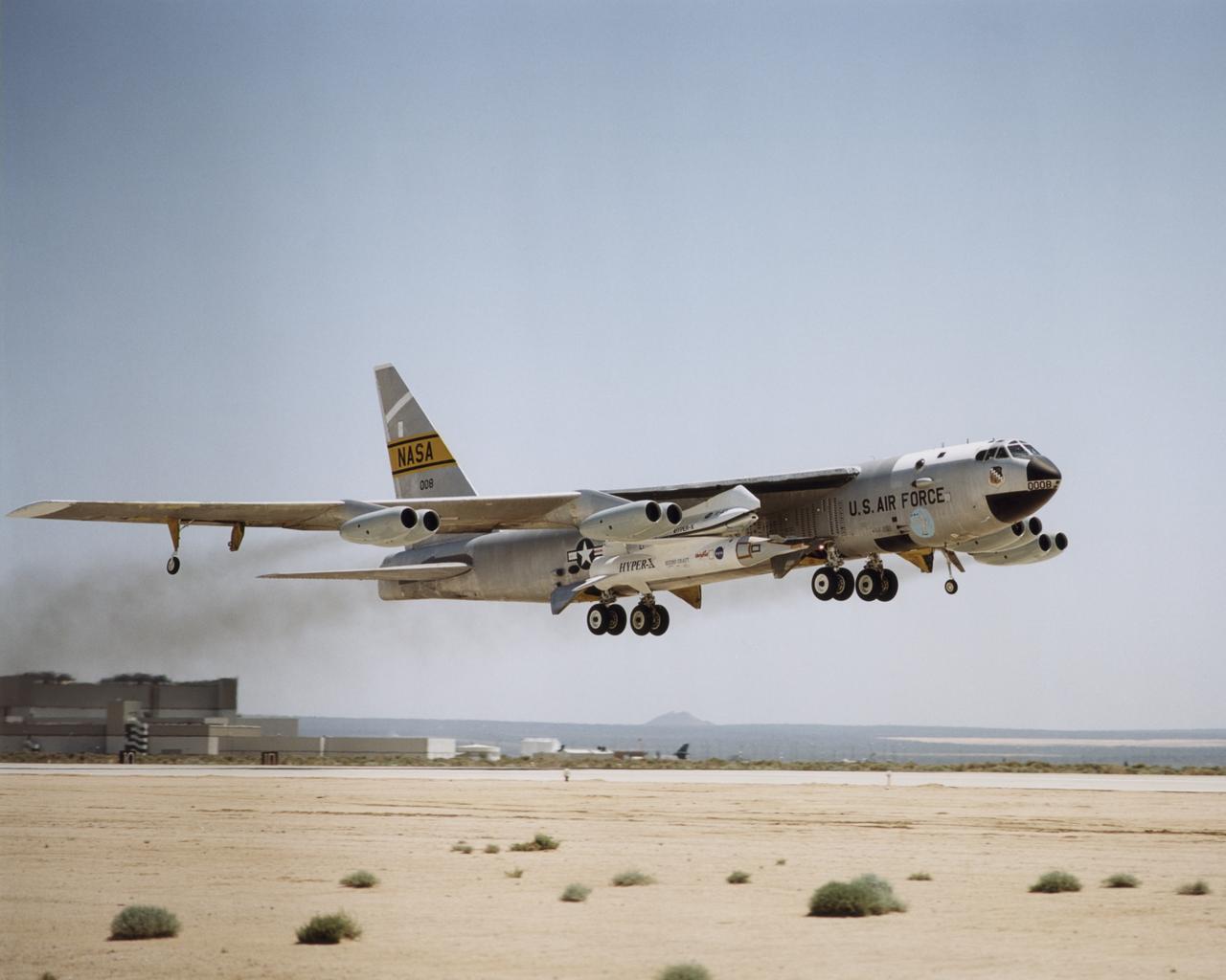
The NASA X-43A hypersonic research vehicle and its Pegasus booster rocket, mounted beneath the wing of their B-52 mothership, had a successful first captive-carry flight on April 28, 2001, Basically a dress rehearsal for a subsequent free flight, the captive-carry flight kept the X-43A-and-Pegasus combination attached to the B-52's wing pylon throughout the almost two-hour mission from NASA's Dryden Flight Research Center, Edwards, Calif., over the Pacific Missile Test Range, and back to Dryden.
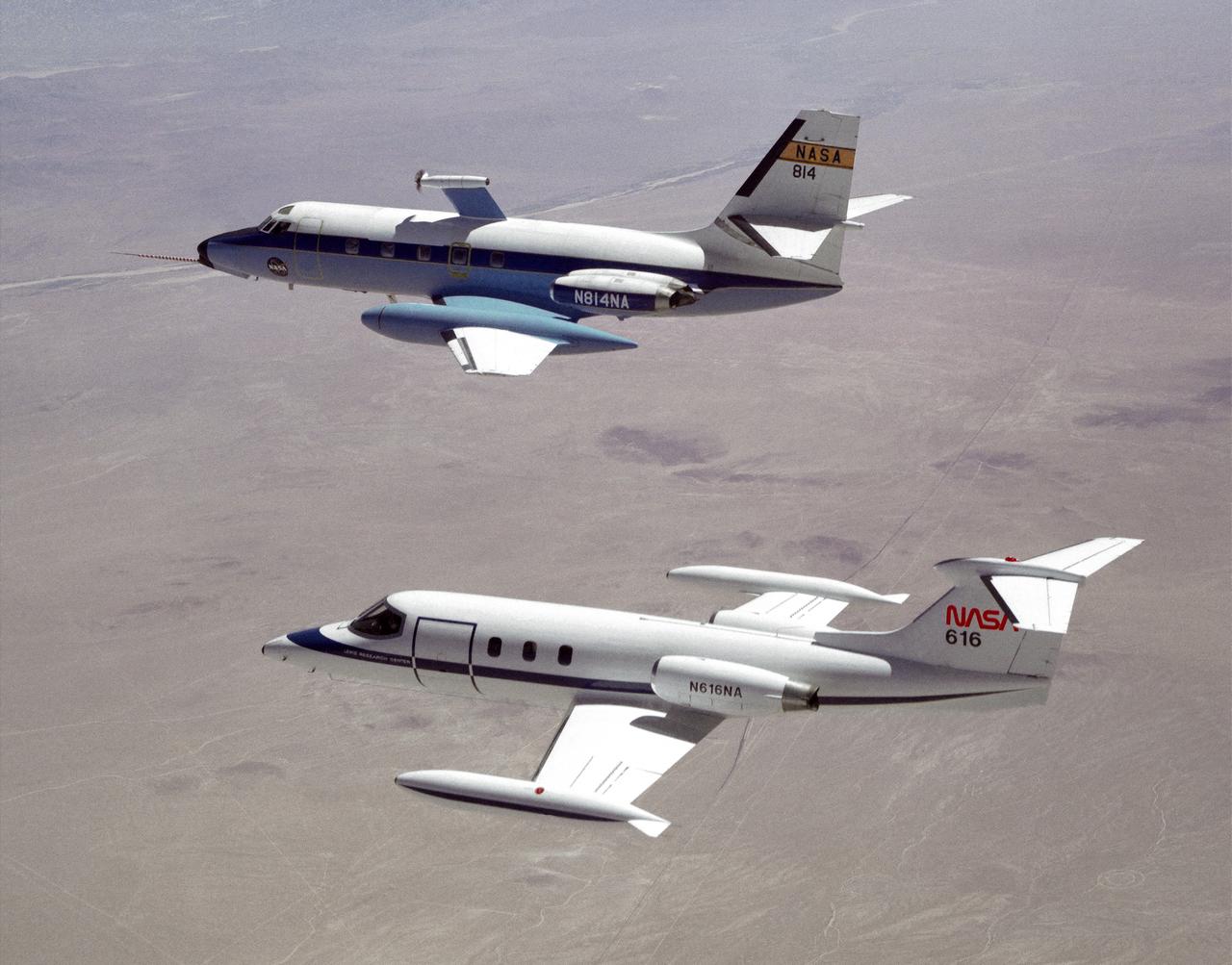
The NASA C-140 JetStar research aircraft (top) is followed by a NASA Learjet equipped with acoustic sensors during one of several tests of advanced propellors mounted on the vertical pylon atop the JetStar's fuselage. Several advanced prop designs were tested on the JetStar in 1982 by NASA's Dryden Flight Research Facility (DFRF), Edwards, California, to study the effects of noise created by propellors on aircraft structures and cabin interiors. To assess possible noise problems with the subscale turbofan, DFRF technicians mounted microphones on both the JetStar and the Learjet chase plane. DFRF then made measurements at close range and at longer distances. The data enabled structural changes and flightpath modifications.
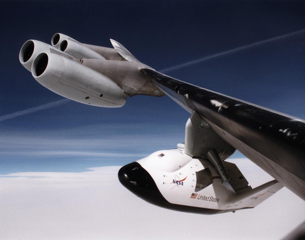
A unique, close-up view of the X-38 under the wing of NASA's B-52 mothership prior to launch of the lifting-body research vehicle. The photo was taken from the observation window of the B-52 bomber as it banked in flight.

ISS010-E-05070 (25 October 2004) --- Corrientes, Argentina, and the Parana River are featured in this image photographed by an Expedition 10 crewmember on the International Space Station (ISS). Corrientes, Argentina sits on the east bank of the Parana River, South America’s third largest river (after the Negro and Amazon Rivers). From its headwaters in southeastern Brazil, the river flows southwestward around southern Paraguay, and then into Argentina. Corrientes is located just inside Argentina, across the river from the southwestern tip of Paraguay. The bridge over the Parana, built in the 1970s, connects Corrientes to its sister city, Resistencia, (beyond the left edge of image) on the western bank of the river. Sun glint on the river gives it a silvery glow and emphasizes channel islands in the river, side channels, and meander scars on the floodplain opposite the city, and even reveals the pattern of disturbed flow downstream of the bridge pylons. The old part of the city appears as a zone of smaller, more densely clustered city blocks along the river to the north of a major highway, which runs through Corrientes from the General Belgrano Bridge to the northeast (upper right of image). Larger blocks of the younger cityscape, with more green space, surround these core neighborhoods.
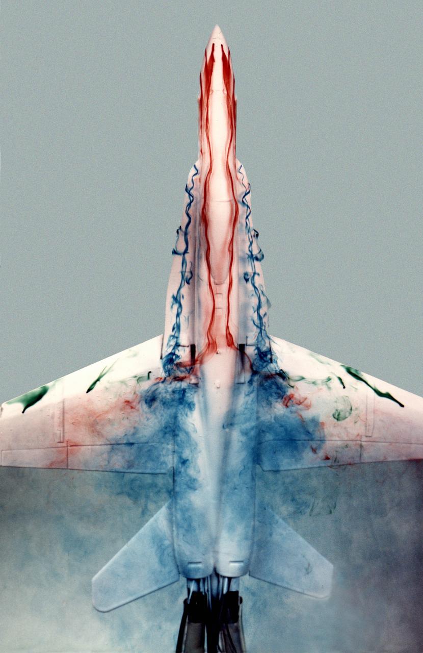
This image shows a plastic 1/48-scale model of an F-18 aircraft inside the "Water Tunnel" more formally known as the NASA Dryden Flow Visualization Facility. Water is pumped through the tunnel in the direction of normal airflow over the aircraft; then, colored dyes are pumped through tubes with needle valves. The dyes flow back along the airframe and over the airfoils highlighting their aerodynamic characteristics. The aircraft can also be moved through its pitch axis to observe airflow disruptions while simulating actual flight at high angles of attack. The Water Tunnel at NASA's Dryden Flight Research Center, Edwards, CA, became operational in 1983 when Dryden was a Flight Research Facility under the management of the Ames Research Center in Mountain View, CA. As a medium for visualizing fluid flow, water has played a significant role. Its use dates back to Leonardo da Vinci (1452-1519), the Renaissance Italian engineer, architect, painter, and sculptor. In more recent times, water tunnels have assisted the study of complex flows and flow-field interactions on aircraft shapes that generate strong vortex flows. Flow visualization in water tunnels assists in determining the strength of vortices, their location, and possible methods of controlling them. The design of the Dryden Water Tunnel imitated that of the Northrop Corporation's tunnel in Hawthorne, CA. Called the Flow Visualization Facility, the Dryden tunnel was built to assist researchers in understanding the aerodynamics of aircraft configured in such a way that they create strong vortex flows, particularly at high angles of attack. The tunnel provides results that compare well with data from aircraft in actual flight in another fluid-air. Other uses of the tunnel have included study of how such flight hardware as antennas, probes, pylons, parachutes, and experimental fixtures affect airflow. The facility has also been helpful in finding the best locations for emitting smoke from flight vehicles for flow vi
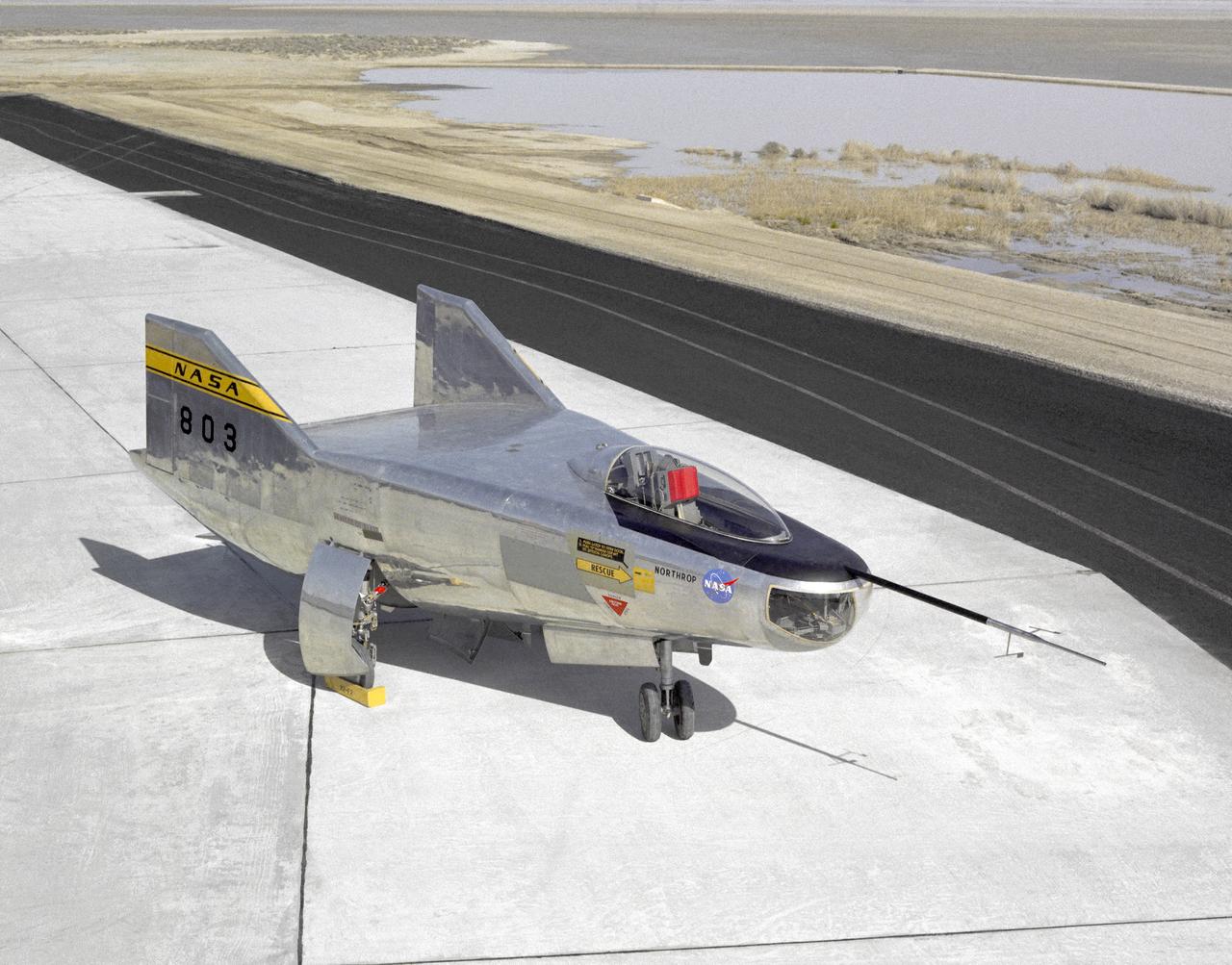
The M2-F2 Lifting Body is seen here on the ramp at the NASA Dryden Flight Research Center. The success of Dryden's M2-F1 program led to NASA's development and construction of two heavyweight lifting bodies based on studies at NASA's Ames and Langley research centers -- the M2-F2 and the HL-10, both built by the Northrop Corporation. The "M" refers to "manned" and "F" refers to "flight" version. "HL" comes from "horizontal landing" and 10 is for the tenth lifting body model to be investigated by Langley. The first flight of the M2-F2 -- which looked much like the "F1" -- was on July 12, 1966. Milt Thompson was the pilot. By then, the same B-52 used to air launch the famed X-15 rocket research aircraft was modified to also carry the lifting bodies. Thompson was dropped from the B-52's wing pylon mount at an altitude of 45,000 feet on that maiden glide flight. The M2-F2 weighed 4,620 pounds, was 22 feet long, and had a width of about 10 feet. On May 10, 1967, during the sixteenth glide flight leading up to powered flight, a landing accident severely damaged the vehicle and seriously injured the NASA pilot, Bruce Peterson. NASA pilots and researchers realized the M2-F2 had lateral control problems, even though it had a stability augmentation control system. When the M2-F2 was rebuilt at Dryden and redesignated the M2-F3, it was modified with an additional third vertical fin -- centered between the tip fins -- to improve control characteristics. The M2-F2/F3 was the first of the heavy-weight, entry-configuration lifting bodies. Its successful development as a research test vehicle answered many of the generic questions about these vehicles. NASA donated the M2-F3 vehicle to the Smithsonian Institute in December 1973. It is currently hanging in the Air and Space Museum along with the X-15 aircraft number 1, which was its hangar partner at Dryden from 1965 to 1969.
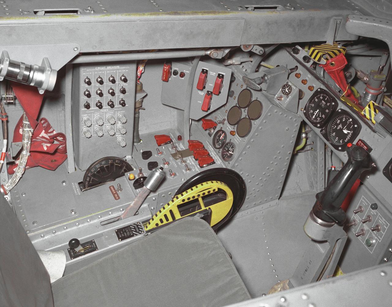
This photo shows the left side cockpit instrumentation panel of the M2-F2 Lifting Body. The success of Dryden's M2-F1 program led to NASA's development and construction of two heavyweight lifting bodies based on studies at NASA's Ames and Langley research centers -- the M2-F2 and the HL-10, both built by the Northrop Corporation. The "M" refers to "manned" and "F" refers to "flight" version. "HL" comes from "horizontal landing" and 10 is for the tenth lifting body model to be investigated by Langley. The first flight of the M2-F2 -- which looked much like the "F1" -- was on July 12, 1966. Milt Thompson was the pilot. By then, the same B-52 used to air launch the famed X-15 rocket research aircraft was modified to also carry the lifting bodies. Thompson was dropped from the B-52's wing pylon mount at an altitude of 45,000 feet on that maiden glide flight. The M2-F2 weighed 4,620 pounds, was 22 feet long, and had a width of about 10 feet. On May 10, 1967, during the sixteenth glide flight leading up to powered flight, a landing accident severely damaged the vehicle and seriously injured the NASA pilot, Bruce Peterson. NASA pilots and researchers realized the M2-F2 had lateral control problems, even though it had a stability augmentation control system. When the M2-F2 was rebuilt at Dryden and redesignated the M2-F3, it was modified with an additional third vertical fin -- centered between the tip fins -- to improve control characteristics. The M2-F2/F3 was the first of the heavy-weight, entry-configuration lifting bodies. Its successful development as a research test vehicle answered many of the generic questions about these vehicles. NASA donated the M2-F3 vehicle to the Smithsonian Institute in December 1973. It is currently hanging in the Air and Space Museum along with the X-15 aircraft number 1, which was its hangar partner at Dryden from 1965 to 1969.
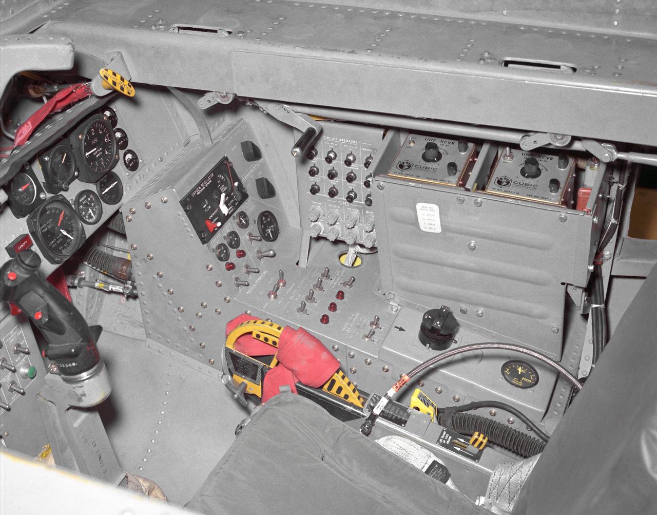
This photo shows the right side cockpit instrumentation panel of the M2-F2 Lifting Body. The success of Dryden's M2-F1 program led to NASA's development and construction of two heavyweight lifting bodies based on studies at NASA's Ames and Langley research centers -- the M2-F2 and the HL-10, both built by the Northrop Corporation. The "M" refers to "manned" and "F" refers to "flight" version. "HL" comes from "horizontal landing" and 10 is for the tenth lifting body model to be investigated by Langley. The first flight of the M2-F2 -- which looked much like the "F1" -- was on July 12, 1966. Milt Thompson was the pilot. By then, the same B-52 used to air launch the famed X-15 rocket research aircraft was modified to also carry the lifting bodies. Thompson was dropped from the B-52's wing pylon mount at an altitude of 45,000 feet on that maiden glide flight. The M2-F2 weighed 4,620 pounds, was 22 feet long, and had a width of about 10 feet. On May 10, 1967, during the sixteenth glide flight leading up to powered flight, a landing accident severely damaged the vehicle and seriously injured the NASA pilot, Bruce Peterson. NASA pilots and researchers realized the M2-F2 had lateral control problems, even though it had a stability augmentation control system. When the M2-F2 was rebuilt at Dryden and redesignated the M2-F3, it was modified with an additional third vertical fin -- centered between the tip fins -- to improve control characteristics. The M2-F2/F3 was the first of the heavy-weight, entry-configuration lifting bodies. Its successful development as a research test vehicle answered many of the generic questions about these vehicles. NASA donated the M2-F3 vehicle to the Smithsonian Institute in December 1973. It is currently hanging in the Air and Space Museum along with the X-15 aircraft number 1, which was its hangar partner at Dryden from 1965 to 1969.