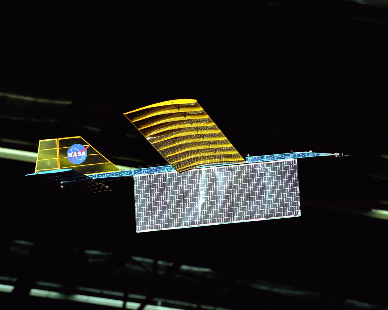
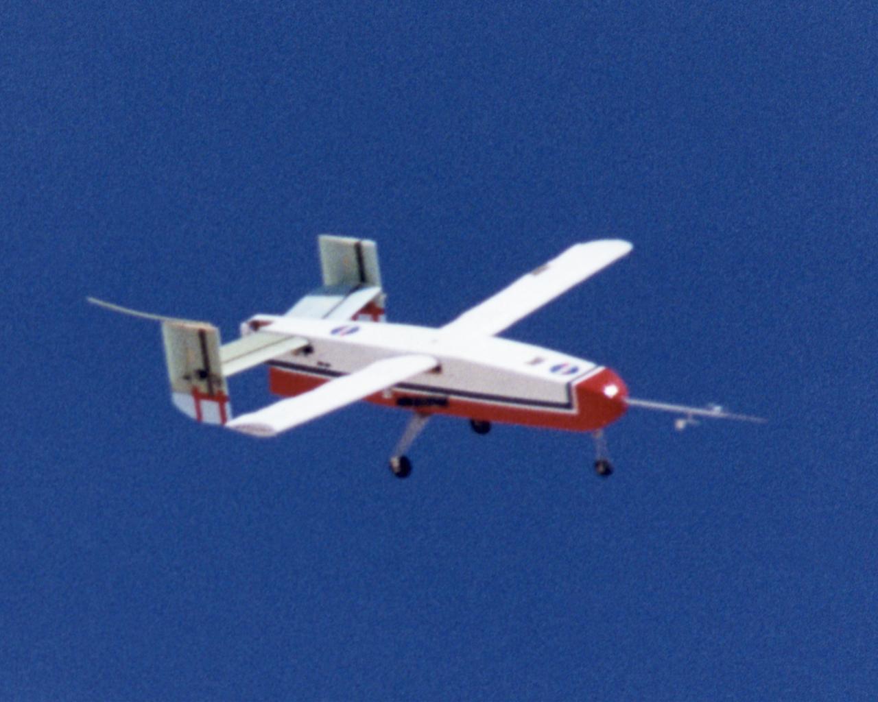
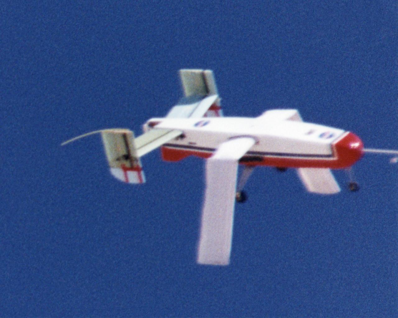
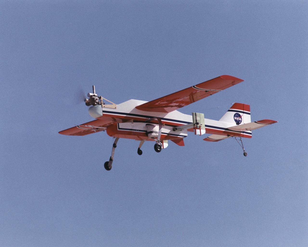
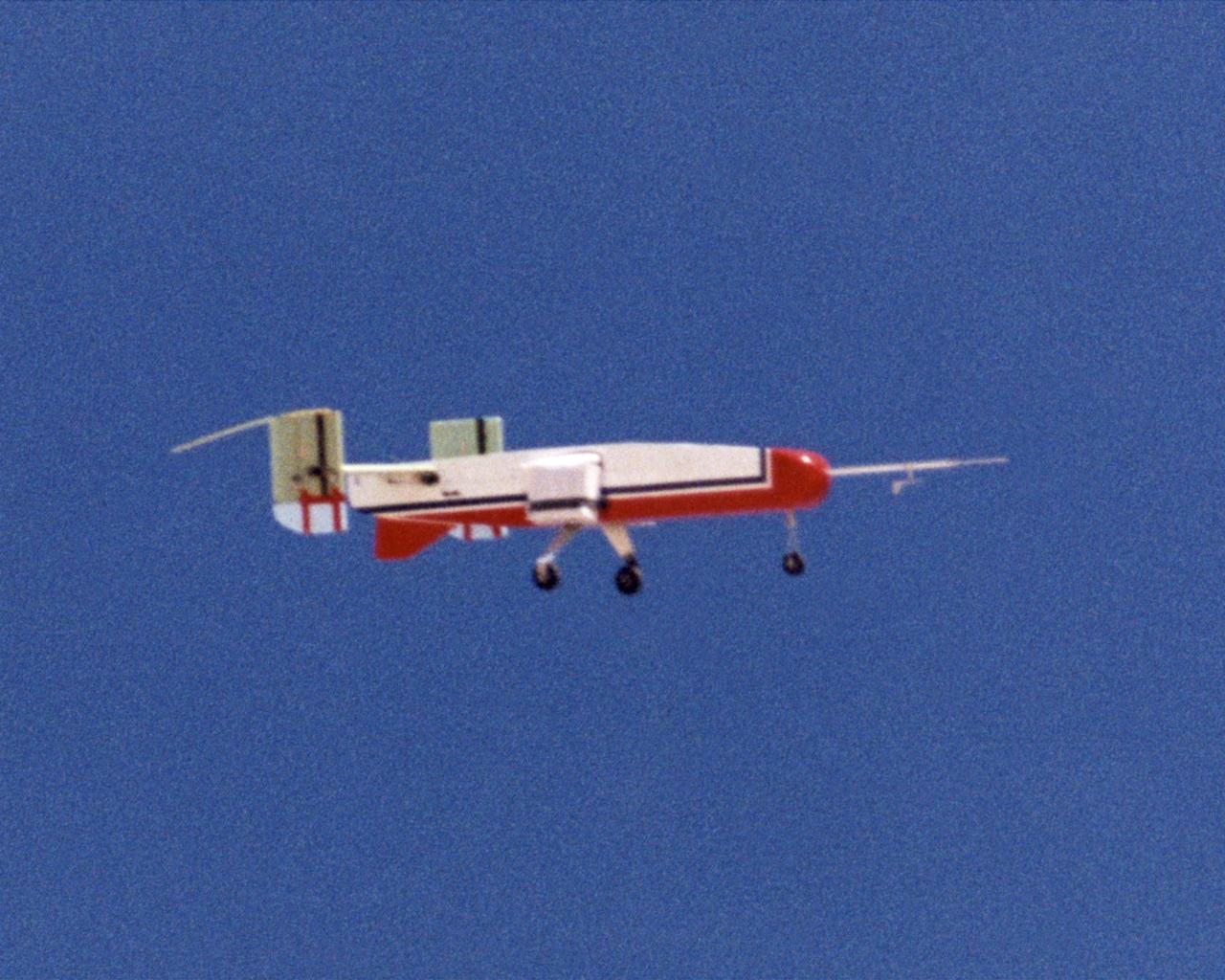
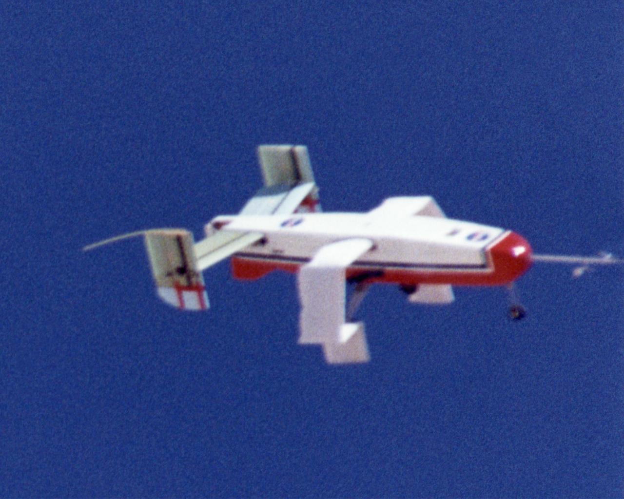
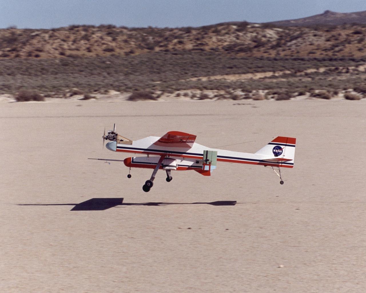
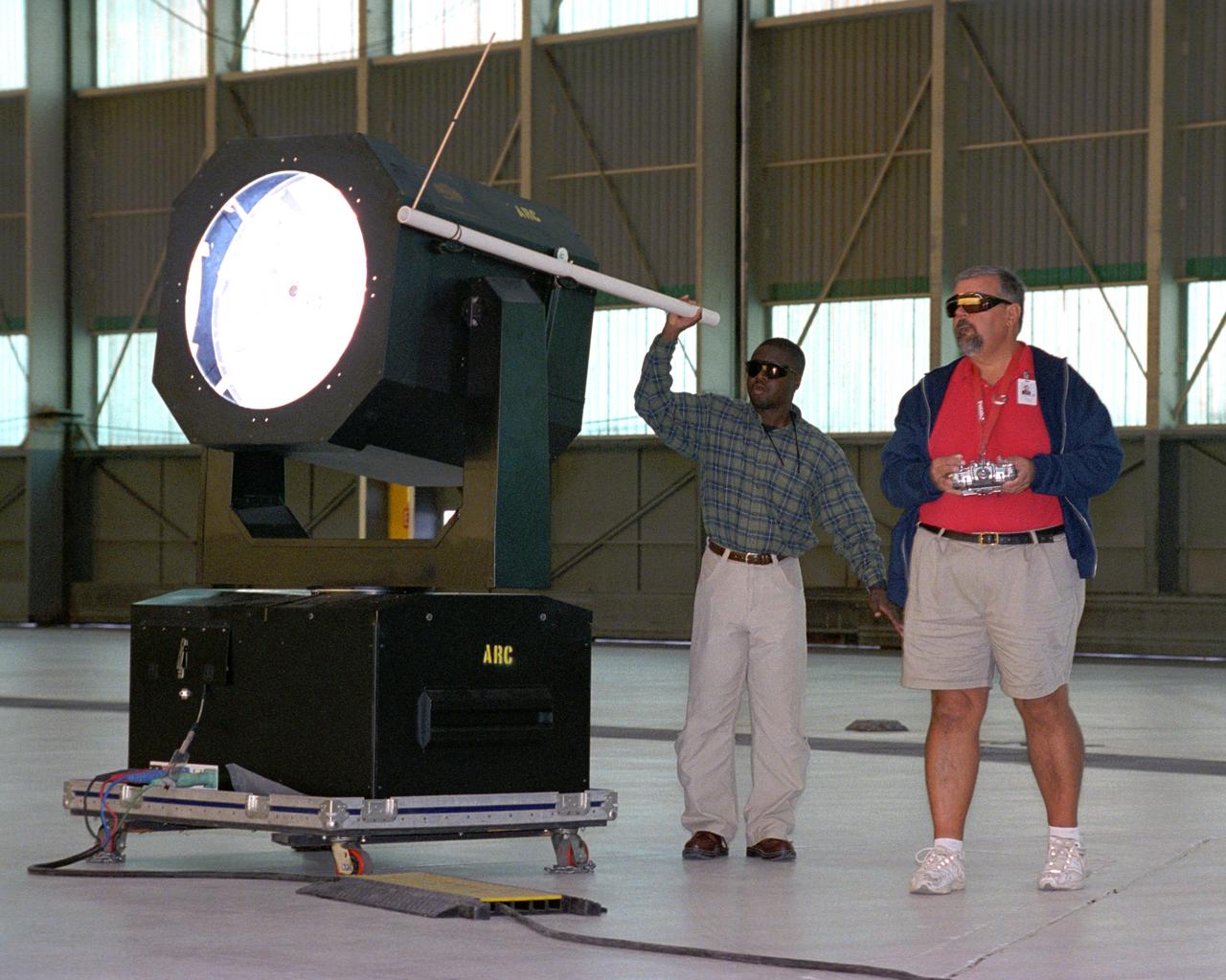
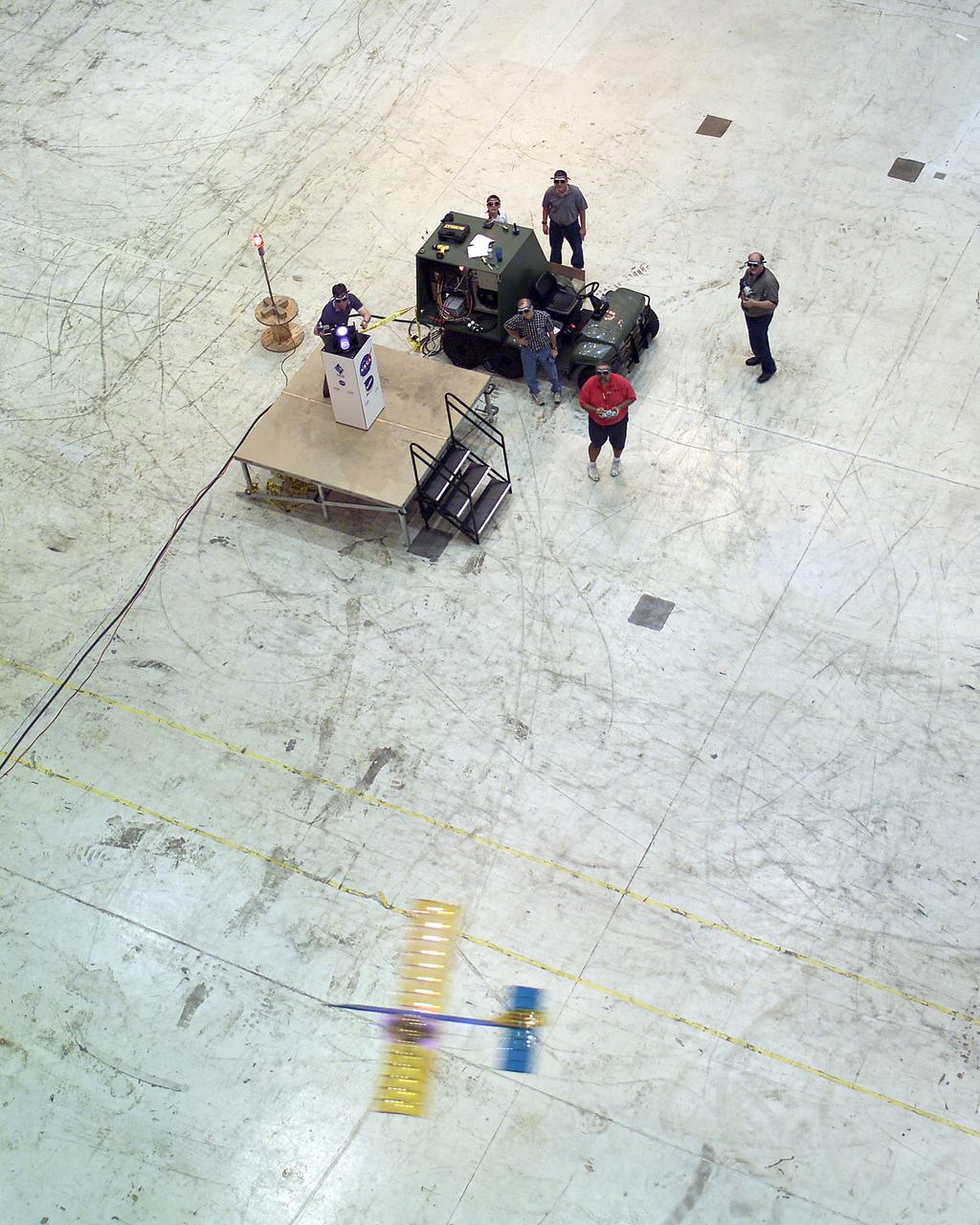
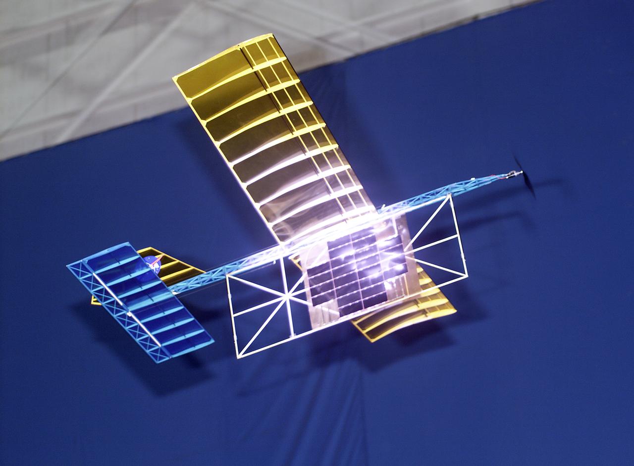
An experimental radio-controlled model aircraft is seen here in flight, powered only by light energy beamed to it by a spotlight.
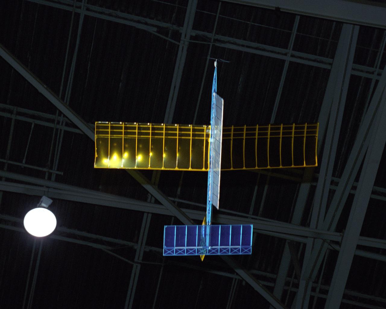
An experimental radio-controlled model aircraft is seen here in flight powered only by light energy beamed to it by a spotlight.

An experimental radio-controlled model aircraft is seen here in flight powered only by light energy beamed to it by a spotlight.
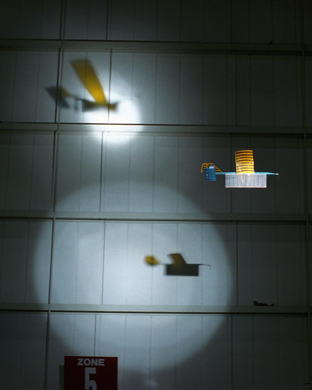
An experimental radio-controlled model aircraft casts two unique shadows as it flies inside a Dryden hangar using two spotlights as energy sources. This phase of testing was used to develop procedures and operations for "handing off" the aircraft between different sources of power.
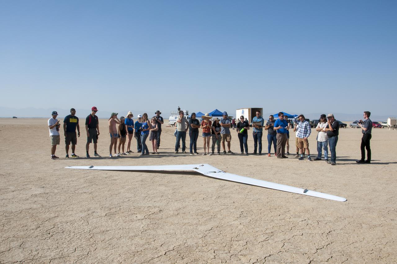
Student interns and NASA personnel cluster in front of PRANDTL-D No. 3 following a crash on Rosamond Dry Lake. The radio-controlled glider was built to validate a new spanload.
Wing Deployment Sequence #3: The deployable, inflatable wing technology demonstrator experiment aircraft's wings fully deployed during flight following separation from its carrier aircraft during a flight conducted by the NASA Dryden Flight Research Center, Edwards, Californiaornia. The inflatable wing project represented a basic flight research effort by Dryden personnel. Three successful flights of the I2000 inflatable wing aircraft occurred. During the flights, the team air-launched the radio-controlled (R/C) I2000 from an R/C utility airplane at an altitude of 800-1000 feet. As the I2000 separated from the carrier aircraft, its inflatable wings "popped-out," deploying rapidly via an on-board nitrogen bottle. The aircraft remained stable as it transitioned from wingless to winged flight. The unpowered I2000 glided down to a smooth landing under complete control.
Inflatable Wing project personnel prepare a deployable, inflatable wing technology demonstrator experiment flown by the NASA Dryden Flight Research Center, Edwards, California. The inflatable wing project represented a basic flight research effort by Dryden personnel. Three successful flights of the I2000 inflatable wing aircraft occurred. During the flights, the team air-launched the radio-controlled (R/C) I2000 from an R/C utility airplane at an altitude of 800-1000 feet. As the I2000 separated from the carrier aircraft, its inflatable wings "popped-out," deploying rapidly via an on-board nitrogen bottle. The aircraft remained stable as it transitioned from wingless to winged flight. The unpowered I2000 glided down to a smooth landing under complete control.
Wing Deployment Sequence #2: The deployable, inflatable wing technology demonstrator experiment aircraft's wings continue deploying following separation from its carrier aircraft during a flight conducted by the NASA Dryden Flight Research Center, Edwards, California. The inflatable wing project represented a basic flight research effort by Dryden personnel. Three successful flights of the I2000 inflatable wing aircraft occurred. During the flights, the team air-launched the radio-controlled (R/C) I2000 from an R/C utility airplane at an altitude of 800-1000 feet. As the I2000 separated from the carrier aircraft, its inflatable wings "popped-out," deploying rapidly via an on-board nitrogen bottle. The aircraft remained stable as it transitioned from wingless to winged flight. The unpowered I2000 glided down to a smooth landing under complete control.
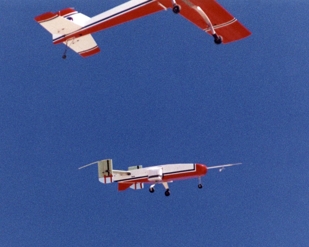
The deployable, inflatable wing technology demonstrator experiment separates from its carrier aircraft during a flight conducted by the NASA Dryden Flight Research Center, Edwards, California. The inflatable wing project represented a basic flight research effort by Dryden personnel. Three successful flights of the I2000 inflatable wing aircraft occurred. During the flights, the team air-launched the radio-controlled (R/C) I2000 from an R/C utility airplane at an altitude of 800-1000 feet. As the I2000 separated from the carrier aircraft, its inflatable wings "popped-out," deploying rapidly via an on-board nitrogen bottle. The aircraft remained stable as it transitioned from wingless to winged flight. The unpowered I2000 glided down to a smooth landing under complete control.
The deployable, inflatable wing technology demonstrator experiment aircraft looks good during a flight conducted by the NASA Dryden Flight Research Center, Edwards, California. The inflatable wing project represented a basic flight research effort by Dryden personnel. Three successful flights of the I2000 inflatable wing aircraft occurred. During the flights, the team air-launched the radio-controlled (R/C) I2000 from an R/C utility airplane at an altitude of 800-1000 feet. As the I2000 separated from the carrier aircraft, its inflatable wings "popped-out," deploying rapidly via an on-board nitrogen bottle. The aircraft remained stable as it transitioned from wingless to winged flight. The unpowered I2000 glided down to a smooth landing under complete control.
The deployable, inflatable wing technology demonstrator experiment aircraft maintains a steady attitude following separation from its carrier aircraft during a flight conducted by the NASA Dryden Flight Research Center, Edwards, California. The inflatable wing project represented a basic flight research effort by Dryden personnel. Three successful flights of the I2000 inflatable wing aircraft occurred. During the flights, the team air-launched the radio-controlled (R/C) I2000 from an R/C utility airplane at an altitude of 800-1000 feet. As the I2000 separated from the carrier aircraft, its inflatable wings "popped-out," deploying rapidly via an on-board nitrogen bottle. The aircraft remained stable as it transitioned from wingless to winged flight. The unpowered I2000 glided down to a smooth landing under complete control.
Wing Deployment Sequence #1: The deployable, inflatable wing technology demonstrator experiment aircraft's wings begin deploying following separation from its carrier aircraft during a flight conducted by the NASA Dryden Flight Research Center, Edwards, California. The inflatable wing project represented a basic flight research effort by Dryden personnel. Three successful flights of the I2000 inflatable wing aircraft occurred. During the flights, the team air-launched the radio-controlled (R/C) I2000 from an R/C utility airplane at an altitude of 800-1000 feet. As the I2000 separated from the carrier aircraft, its inflatable wings "popped-out," deploying rapidly via an on-board nitrogen bottle. The aircraft remained stable as it transitioned from wingless to winged flight. The unpowered I2000 glided down to a smooth landing under complete control.
Engineers Jim Murray and Joe Pahle prepare a deployable, inflatable wing technology demonstrator experiment flown by the NASA Dryden Flight Research Center, Edwards, California. The inflatable wing project represented a basic flight research effort by Dryden personnel. Three successful flights of the I2000 inflatable wing aircraft occurred. During the flights, the team air-launched the radio-controlled (R/C) I2000 from an R/C utility airplane at an altitude of 800-1000 feet. As the I2000 separated from the carrier aircraft, its inflatable wings "popped-out," deploying rapidly via an on-board nitrogen bottle. The aircraft remained stable as it transitioned from wingless to winged flight. The unpowered I2000 glided down to a smooth landing under complete control.

iss050e041989 (2/14/2017) --- Photo documentation of the Radio Frequency Identification (RFID) cable installation in the U.S. Laboratory aboard the International Space Station (ISS). The RFID-Enabled Autonomous Logistics Management (REALM) (RFID Logistics Awareness) investigation tests a radio-based inventory control system to keep track of everything inside the football-field-sized ISS. Some aspects of the technology are commonly used on Earth, but other aspects are experimental in nature.
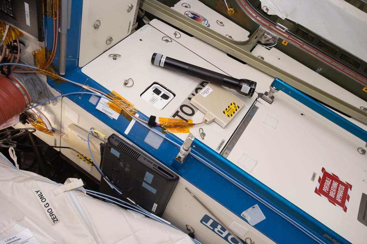
iss050e041985 (2/14/2017) --- Photo documentation of the Radio Frequency Identification (RFID) cable installation in the U.S. Laboratory aboard the International Space Station (ISS). The RFID-Enabled Autonomous Logistics Management (REALM) (RFID Logistics Awareness) investigation tests a radio-based inventory control system to keep track of everything inside the football-field-sized ISS. Some aspects of the technology are commonly used on Earth, but other aspects are experimental in nature.
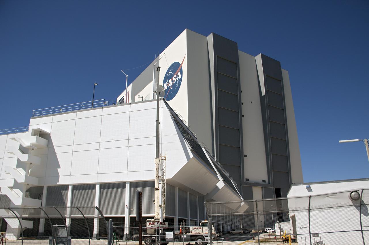
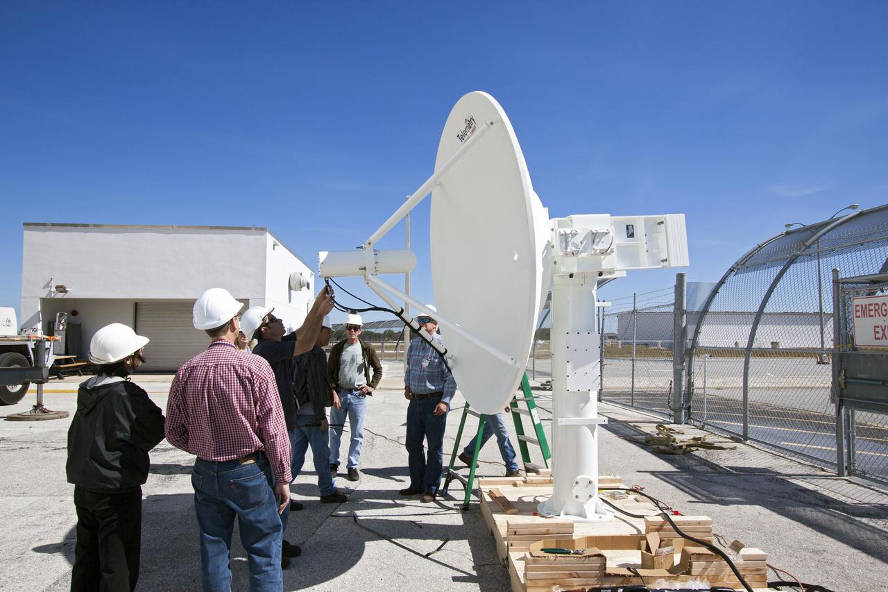
CAPE CANAVERAL, Fla. – A telemetry antenna and tracker camera is attached to the roof of the Launch Control Center, or LCC, in Launch Complex 39 at NASA's Kennedy Space Center in Florida. This antenna and camera system is the first of three to be installed on the LCC roof for the Radio Frequency and Telemetry Station RFTS, which will be used to monitor radio frequency communications from a launch vehicle at Launch Pad 39A or B as well as provide radio frequency relay for a launch vehicle in the Vehicle Assembly Building. The RFTS replaces the shuttle-era communications and tracking labs at Kennedy. The modern RFTS checkout station is designed to primarily support NASA's Space Launch System, or SLS, and Orion spacecraft, but can support multi-user radio frequency tests as the space center transitions to support a variety of rockets and spacecraft. For more information on the modernization efforts at Kennedy, visit the Ground Systems Development and Operations, or GSDO, website at http://go.nasa.gov/groundsystems. Photo credit: NASA/Jim Grossmann
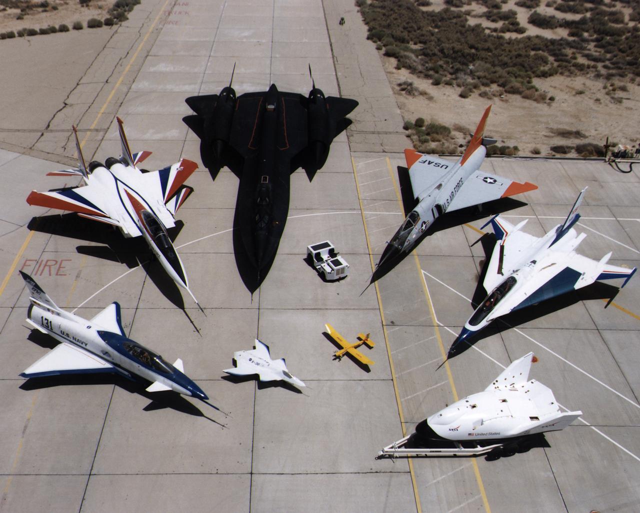
A collection of NASA's research aircraft on the ramp at the Dryden Flight Research Center in July 1997: X-31, F-15 ACTIVE, SR-71, F-106, F-16XL Ship #2, X-38, Radio Controlled Mothership and X-36.
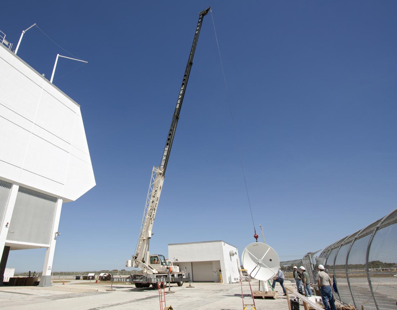
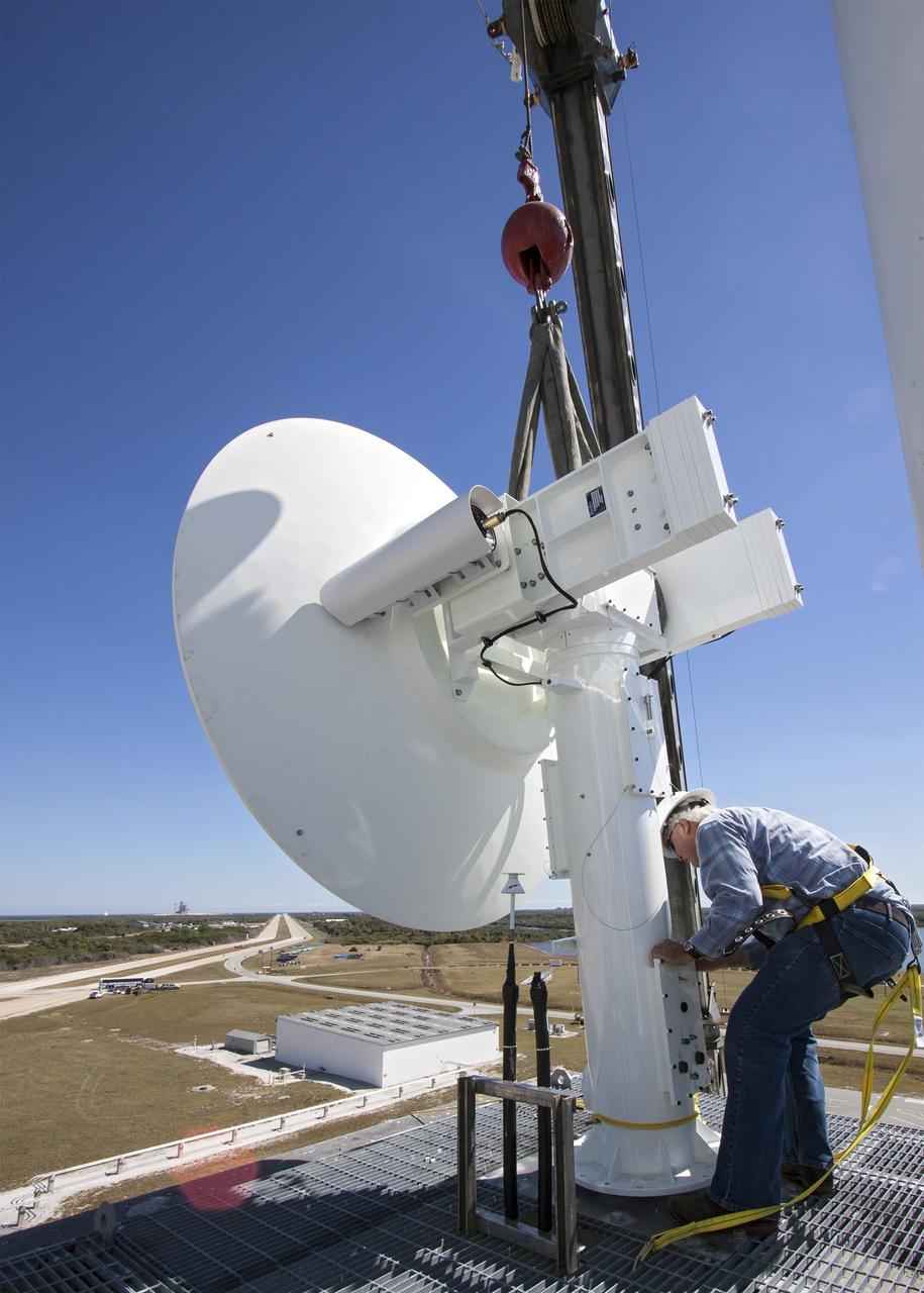
CAPE CANAVERAL, Fla. – Workers use a crane to install a new parabolic telemetry antenna and tracker camera to the roof of the Launch Control Center, or LCC, in Launch Complex 39 at NASA's Kennedy Space Center in Florida. This antenna and camera system is the first of three that will be installed on the LCC roof for the Radio Frequency and Telemetry Station RFTS, which will be used to monitor radio frequency communications from a launch vehicle at Launch Pad 39A or B as well as provide radio frequency relay for a launch vehicle in the Vehicle Assembly Building. The RFTS replaces the shuttle-era communications and tracking labs at Kennedy. The modern RFTS checkout station is designed to primarily support NASA's Space Launch System, or SLS, and Orion spacecraft, but can support multi-user radio frequency tests as the space center transitions to support a variety of rockets and spacecraft. For more information on the modernization efforts at Kennedy, visit the Ground Systems Development and Operations, or GSDO, website at http:__go.nasa.gov_groundsystems. Photo credit: NASA_Jim Grossmann
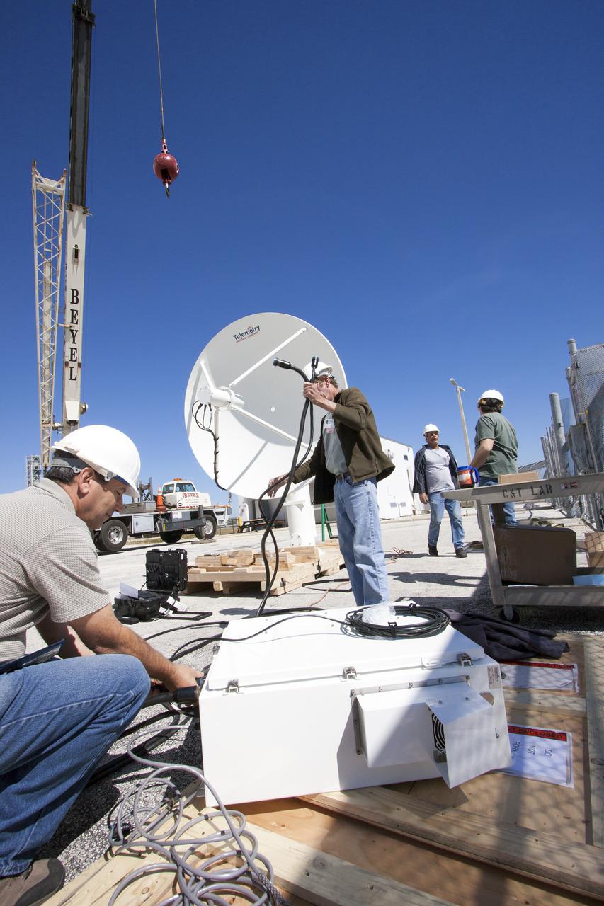
CAPE CANAVERAL, Fla. – Workers prepare to install a new parabolic telemetry antenna and tracker camera to the roof of the Launch Control Center, or LCC, in Launch Complex 39 at NASA's Kennedy Space Center in Florida. This antenna and camera system is the first of three that will be installed on the LCC roof for the Radio Frequency and Telemetry Station RFTS, which will be used to monitor radio frequency communications from a launch vehicle at Launch Pad 39A or B as well as provide radio frequency relay for a launch vehicle in the Vehicle Assembly Building. The RFTS replaces the shuttle-era communications and tracking labs at Kennedy. The modern RFTS checkout station is designed to primarily support NASA's Space Launch System, or SLS, and Orion spacecraft, but can support multi-user radio frequency tests as the space center transitions to support a variety of rockets and spacecraft. For more information on the modernization efforts at Kennedy, visit the Ground Systems Development and Operations, or GSDO, website at http:__go.nasa.gov_groundsystems. Photo credit: NASA_Jim Grossmann
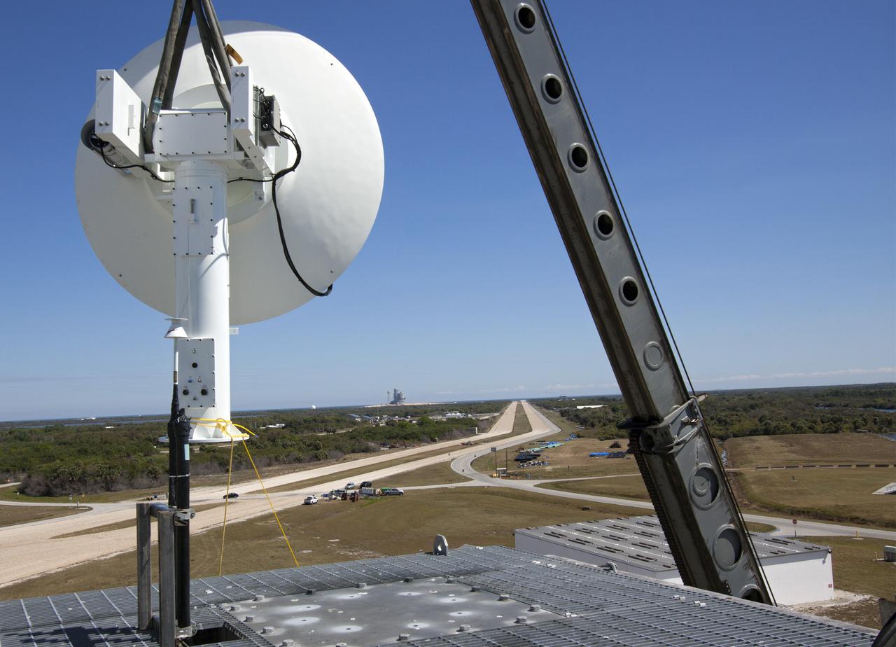
CAPE CANAVERAL, Fla. – With the help of a crane, a worker helps guide a parabolic telemetry antenna and tracker camera to the roof of the Launch Control Center, or LCC, in Launch Complex 39 at NASA's Kennedy Space Center in Florida. This antenna and camera system is the first of three that will be installed on the LCC roof for the Radio Frequency and Telemetry Station RFTS, which will be used to monitor radio frequency communications from a launch vehicle at Launch Pad 39A or B as well as provide radio frequency relay for a launch vehicle in the Vehicle Assembly Building. The RFTS replaces the shuttle-era communications and tracking labs at Kennedy. The modern RFTS checkout station is designed to primarily support NASA's Space Launch System, or SLS, and Orion spacecraft, but can support multi-user radio frequency tests as the space center transitions to support a variety of rockets and spacecraft. For more information on the modernization efforts at Kennedy, visit the Ground Systems Development and Operations, or GSDO, website at http://go.nasa.gov/groundsystems. Photo credit: NASA/Jim Grossmann
CAPE CANAVERAL, Fla. – Workers prepare to install a new parabolic telemetry antenna and tracker camera via crane to the roof of the Launch Control Center, or LCC, in Launch Complex 39 at NASA's Kennedy Space Center in Florida. This antenna and camera system is the first of three that will be installed on the LCC roof for the Radio Frequency and Telemetry Station RFTS, which will be used to monitor radio frequency communications from a launch vehicle at Launch Pad 39A or B as well as provide radio frequency relay for a launch vehicle in the Vehicle Assembly Building. The RFTS replaces the shuttle-era communications and tracking labs at Kennedy. The modern RFTS checkout station is designed to primarily support NASA's Space Launch System, or SLS, and Orion spacecraft, but can support multi-user radio frequency tests as the space center transitions to support a variety of rockets and spacecraft. For more information on the modernization efforts at Kennedy, visit the Ground Systems Development and Operations, or GSDO, website at http:__go.nasa.gov_groundsystems. Photo credit: NASA_Jim Grossmann
CAPE CANAVERAL, Fla. – A crane lifts a new parabolic telemetry antenna and tracker camera to the roof of the Launch Control Center, or LCC, in Launch Complex 39 at NASA's Kennedy Space Center in Florida. This antenna and camera system is the first of three that will be installed on the LCC roof for the Radio Frequency and Telemetry Station RFTS, which will be used to monitor radio frequency communications from a launch vehicle at Launch Pad 39A or B as well as provide radio frequency relay for a launch vehicle in the Vehicle Assembly Building. The RFTS replaces the shuttle-era communications and tracking labs at Kennedy. The modern RFTS checkout station is designed to primarily support NASA's Space Launch System, or SLS, and Orion spacecraft, but can support multi-user radio frequency tests as the space center transitions to support a variety of rockets and spacecraft. For more information on the modernization efforts at Kennedy, visit the Ground Systems Development and Operations, or GSDO, website at http:__go.nasa.gov_groundsystems. Photo credit: NASA_Jim Grossmann

CAPE CANAVERAL, Fla. – A crane lifts a new parabolic telemetry antenna and tracker camera to the roof of the Launch Control Center, or LCC, in Launch Complex 39 at NASA's Kennedy Space Center in Florida. This antenna and camera system is the first of three that will be installed on the LCC roof for the Radio Frequency and Telemetry Station RFTS, which will be used to monitor radio frequency communications from a launch vehicle at Launch Pad 39A or B as well as provide radio frequency relay for a launch vehicle in the Vehicle Assembly Building. The RFTS replaces the shuttle-era communications and tracking labs at Kennedy. The modern RFTS checkout station is designed to primarily support NASA's Space Launch System, or SLS, and Orion spacecraft, but can support multi-user radio frequency tests as the space center transitions to support a variety of rockets and spacecraft. For more information on the modernization efforts at Kennedy, visit the Ground Systems Development and Operations, or GSDO, website at http:__go.nasa.gov_groundsystems. Photo credit: NASA_Jim Grossmann
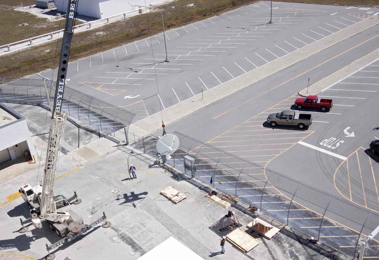
CAPE CANAVERAL, Fla. – Workers use a crane to install a new parabolic telemetry antenna and tracker camera to the roof of the Launch Control Center, or LCC, in Launch Complex 39 at NASA's Kennedy Space Center in Florida. This antenna and camera system is the first of three that will be installed on the LCC roof for the Radio Frequency and Telemetry Station RFTS, which will be used to monitor radio frequency communications from a launch vehicle at Launch Pad 39A or B as well as provide radio frequency relay for a launch vehicle in the Vehicle Assembly Building. The RFTS replaces the shuttle-era communications and tracking labs at Kennedy. The modern RFTS checkout station is designed to primarily support NASA's Space Launch System, or SLS, and Orion spacecraft, but can support multi-user radio frequency tests as the space center transitions to support a variety of rockets and spacecraft. For more information on the modernization efforts at Kennedy, visit the Ground Systems Development and Operations, or GSDO, website at http:__go.nasa.gov_groundsystems. Photo credit: NASA_Jim Grossmann
The I2000, a deployable, inflatable wing technology demonstrator experiment aircraft, leaves the ground during a flight conducted by the NASA Dryden Flight Research Center, Edwards, California.
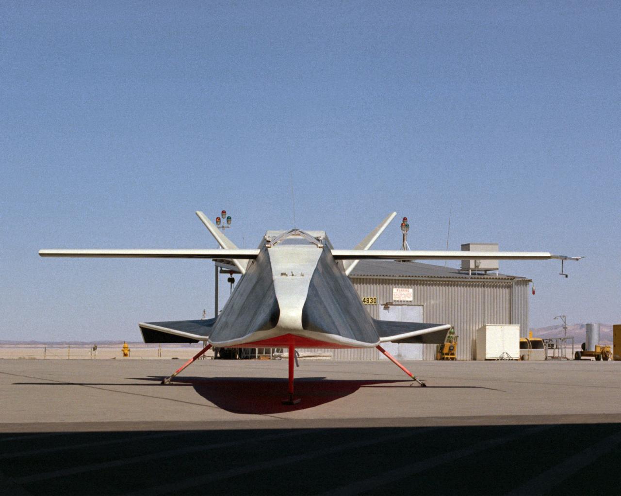
The Hyper III was a low-cost test vehicle for an advanced lifting-body shape. Like the earlier M2-F1, it was a "homebuilt" research aircraft, i.e., built at the Flight Research Center (FRC), later redesignated the Dryden Flight Research Center. It had a steel-tube frame covered with Dacron, a fiberglass nose, sheet aluminum fins, and a wing from an HP-11 sailplane. Construction was by volunteers at the FRC. Although the Hyper III was to be flown remotely in its initial tests, it was fitted with a cockpit for a pilot. On the Hyper III's only flight, it was towed aloft attached to a Navy SH-3 helicopter by a 400-foot cable. NASA research pilot Bruce Peterson flew the SH-3. After he released the Hyper III from the cable, NASA research pilot Milt Thompson flew the vehicle by radio control until the final approach when Dick Fischer took over control using a model-airplane radio-control box. The Hyper III flared, then landed and slid to a stop on Rogers Dry Lakebed.
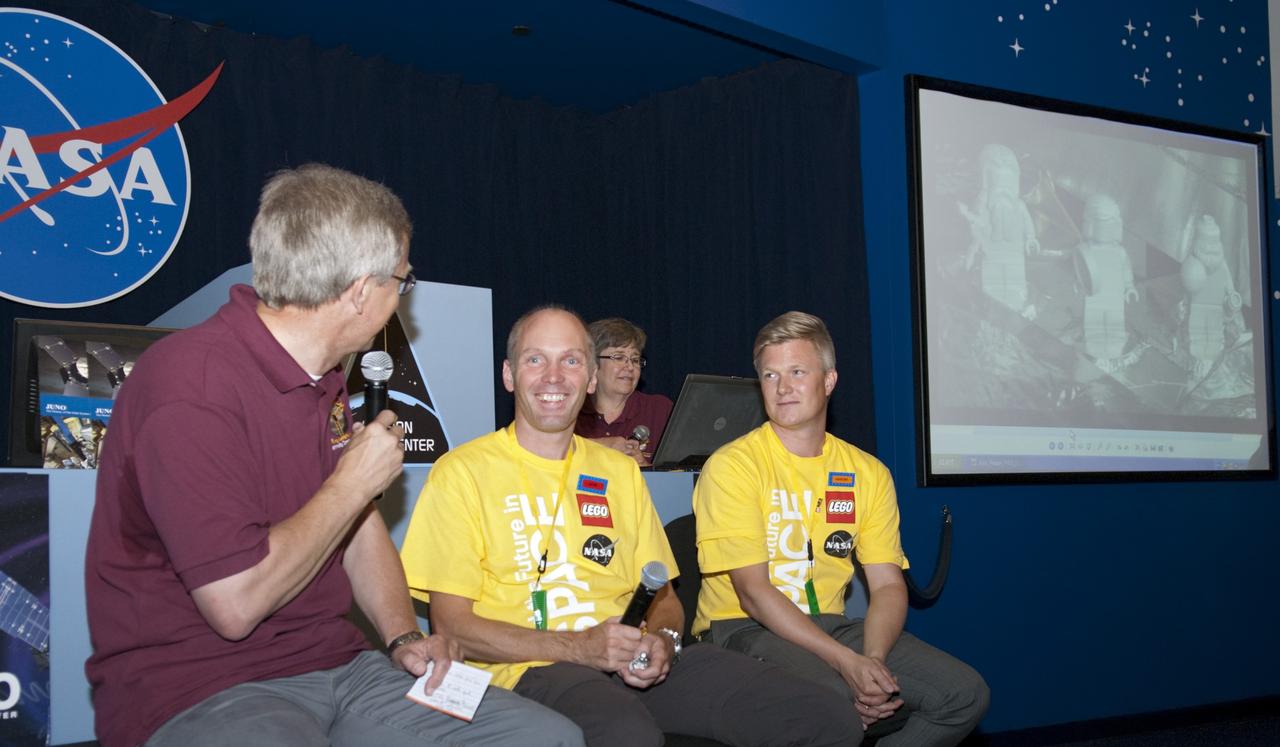
CAPE CANAVERAL, Fla. -- From left, Dr. Steve Lee, with the Denver Museum of Nature and Science; Ulrik Solberg Lund, a LEGO minifigure designer; and Karsten Juel Bunch, a LEGO City senior designer, participate in an educational webcast in the Mission Status Center at the Kennedy Space Center Visitor Complex in Florida. On hand to ask questions of the guests were students, teachers, and mentors of the Goldstone Apple Valley Radio Telescope (GAVRT) project who were invited to Kennedy to watch the launch of NASA's Juno spacecraft atop a United Launch Alliance Atlas V rocket. GAVRT is a partnership between NASA, the Jet Propulsion Laboratory (JPL), and The Lewis Center for Educational Research (LCER) in Apple Valley, Calif. It allows students to control a 34-meter radio telescope that, until recently, was part of NASA’s Deep Space Network, and to interact with scientists outside the classroom setting. Photo credit: NASA/Glenn Benson

CAPE CANAVERAL, Fla. -- Dr. Steve Lee, with the Denver Museum of Nature and Science, left, hosts an educational webcast in the Mission Status Center at the Kennedy Space Center Visitor Complex in Florida. On hand to ask questions were students, teachers, and mentors of the Goldstone Apple Valley Radio Telescope (GAVRT) project who were invited to Kennedy to watch the launch of NASA's Juno spacecraft atop a United Launch Alliance Atlas V rocket. GAVRT is a partnership between NASA, the Jet Propulsion Laboratory (JPL), and The Lewis Center for Educational Research (LCER) in Apple Valley, Calif. It allows students to control a 34-meter radio telescope that, until recently, was part of NASA’s Deep Space Network, and to interact with scientists outside the classroom setting. Photo credit: NASA/Glenn Benson

CAPE CANAVERAL, Fla. -- From left, Dr. Steve Lee, with the Denver Museum of Nature and Science; Ulrik Solberg Lund, a LEGO minifigure designer; and Karsten Juel Bunch, a LEGO City senior designer, participate in an educational webcast in the Mission Status Center at the Kennedy Space Center Visitor Complex in Florida. On hand to ask questions of the guests were students, teachers, and mentors of the Goldstone Apple Valley Radio Telescope (GAVRT) project who were invited to Kennedy to watch the launch of NASA's Juno spacecraft atop a United Launch Alliance Atlas V rocket. GAVRT is a partnership between NASA, the Jet Propulsion Laboratory (JPL), and The Lewis Center for Educational Research (LCER) in Apple Valley, Calif. It allows students to control a 34-meter radio telescope that, until recently, was part of NASA’s Deep Space Network, and to interact with scientists outside the classroom setting. Photo credit: NASA/Glenn Benson
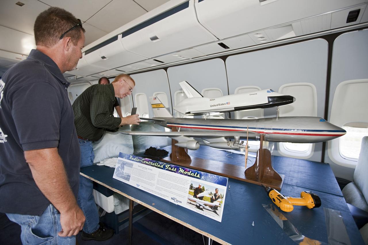
CAPE CANAVERAL, Fla. – Reporters look over a model of the Shuttle Carrier Aircraft, or SCA, and a space shuttle during a tour of the real Shuttle Carrier Aircraft. The model is a radio-controlled scale version of the modified 747 that was used to test theories for how the space shuttle would separate from the SCA during approach and landing tests. Photo credit: NASA/Kim Shiflett
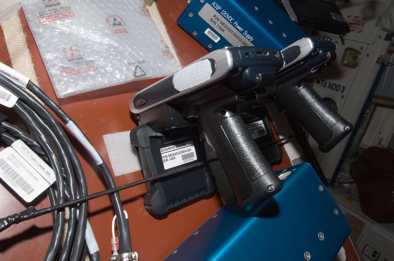
iss028e025734 (8/15/2011) --- Photo documentation of the BCR/RFID Scanner taken aboard the International Space Station(ISS). The RFID-Enabled Autonomous Logistics Management (REALM) (RFID Logistics Awareness) investigation tests a radio-based inventory control system to keep track of everything inside the football-field-sized ISS. Some aspects of the technology are commonly used on Earth, but other aspects are experimental in nature.
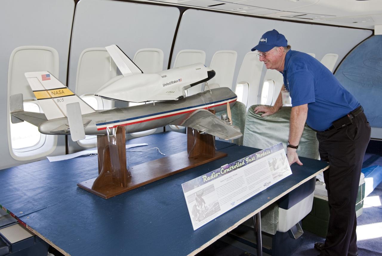
CAPE CANAVERAL, Fla. – A visitor looks over a model of the Shuttle Carrier Aircraft, or SCA, and a space shuttle during a tour of the real Shuttle Carrier Aircraft. The model is a radio-controlled scale version of the modified 747 that was used to test theories for how the space shuttle would separate from the SCA during approach and landing tests. Photo credit: NASA/Kim Shiflett
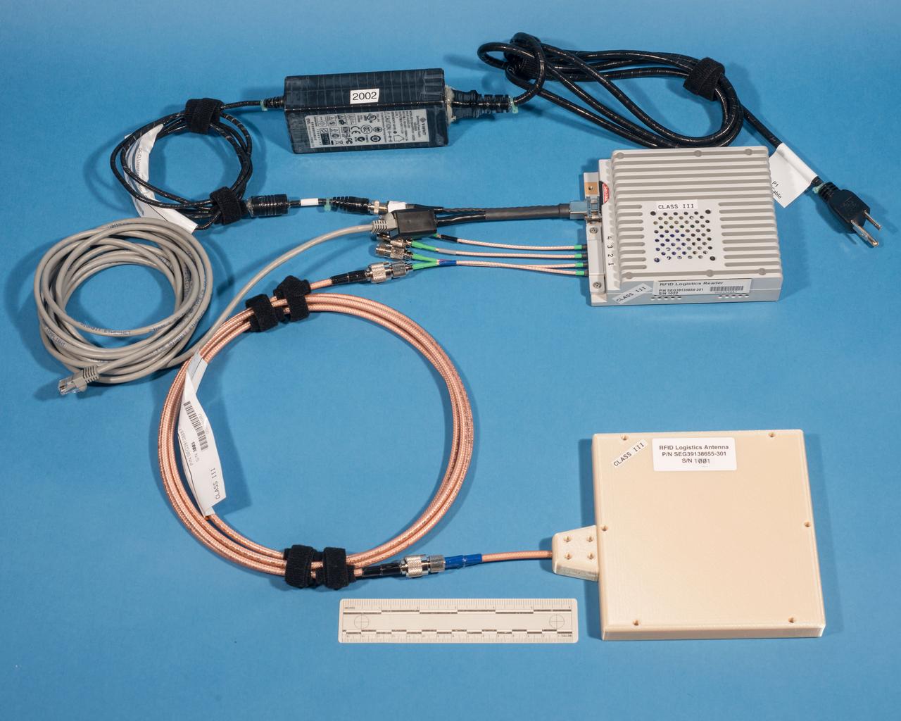
jsc2016e107373 (8/29/2016) --- Photographic documentation taken of REALM-1 (ISS OPNOM RFID Logistics) flight hardware in bldg 14 prior to delivery for launch. The RFID-Enabled Autonomous Logistics Management (REALM) (RFID Logistics Awareness) investigation tests a radio-based inventory control system to keep track of everything inside the football-field-sized ISS. Some aspects of the technology are commonly used on Earth, but other aspects are experimental in nature.
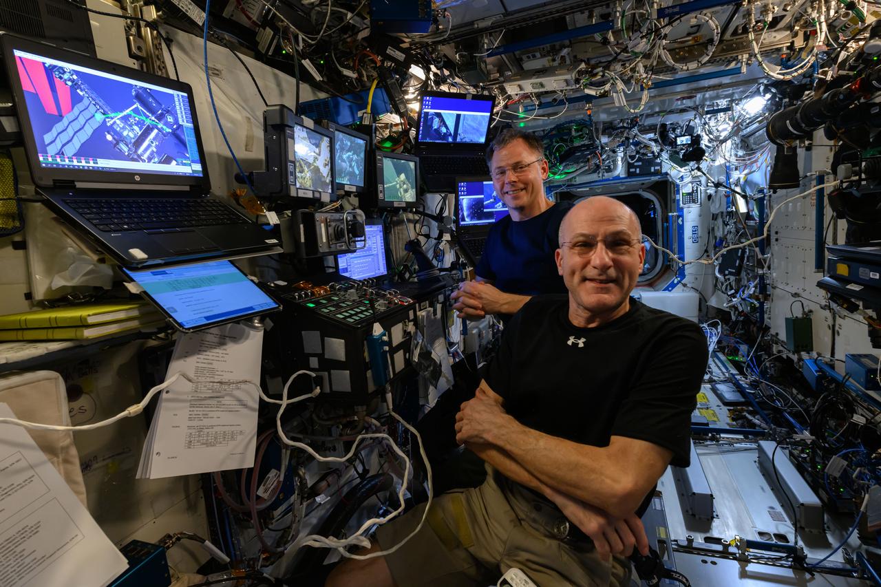
iss072e576545 (Jan. 30, 2025) --- NASA astronauts Don Pettit (foreground) and Nick Hague, both Expedition 72 flight engineers, are at the controls of the robotics workstation preparing to assist and monitor spacewalkers Suni Williams and Butch Wilmore (not pictured). Williams and Wilmore worked outside the International Space Station during a five-hour and 26-minute spacewalk on Jan. 30, 2025, to remove radio communications hardware and swab external surfaces searching for potential microorganisms.
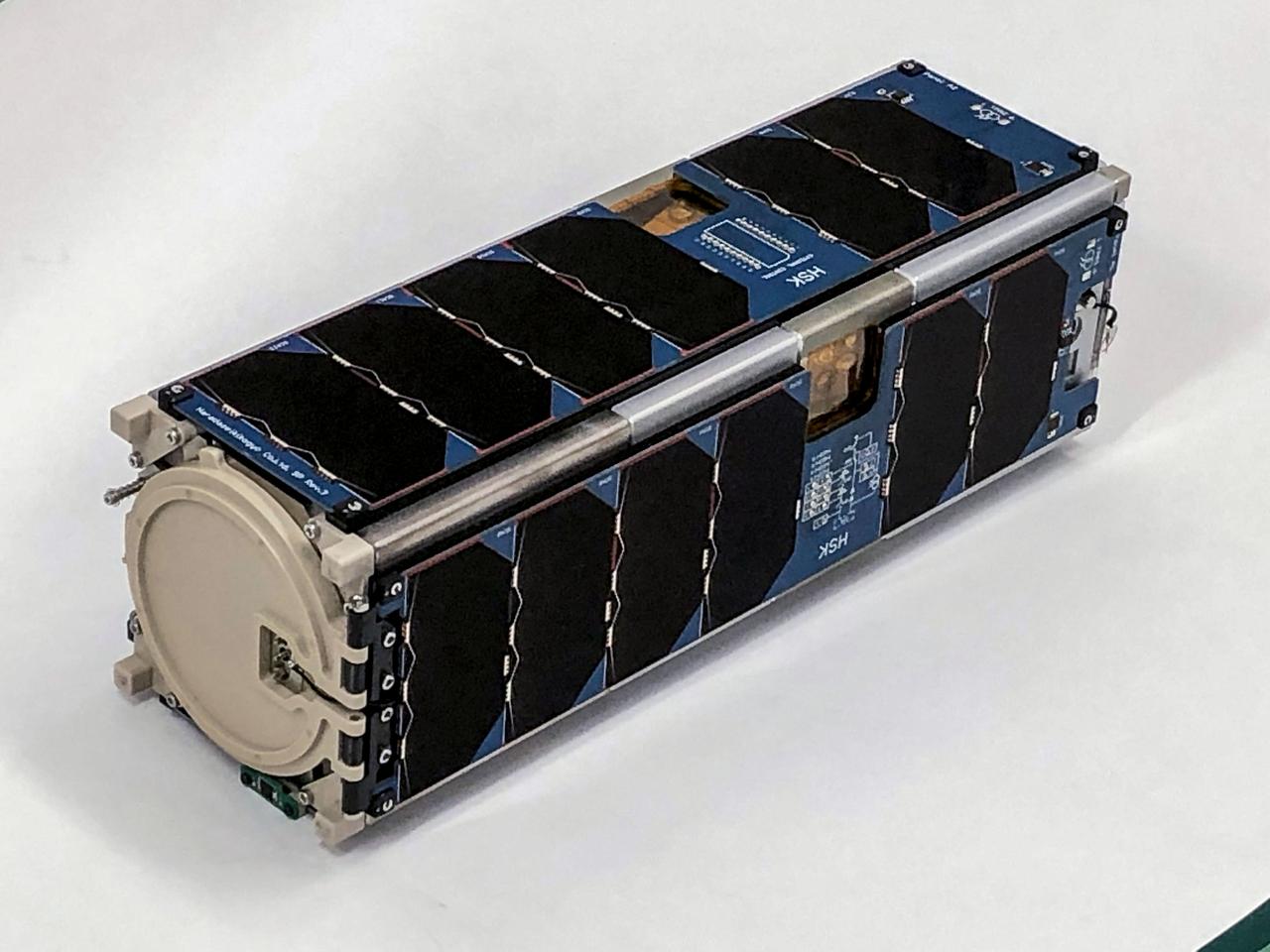
jsc2022e064081 (6/21/2022) --- A preflight view of theHSKSAT Flight Model. HSKSAT is a 3.9 kg, 3-Unit (3U) CubeSat developed by the Harada Seiki Company. HSKSAT's mission is to demonstrate attitude-controlled Earth observation, and provide high-speed imagery downlink utilizing S-band radio communications. Image Credit: Harada Seiki Corporation.
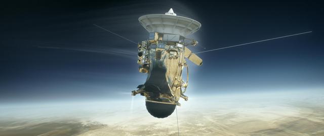
As depicted in this illustration, Cassini will plunge into Saturn's atmosphere on Sept. 15, 2017. Using its attitude control thrusters, the spacecraft will work to keep its antenna pointed at Earth while it sends its final data, including the composition of Saturn's upper atmosphere. The atmospheric torque will quickly become stronger than what the thrusters can compensate for, and after that point, Cassini will begin to tumble. When this happens, its radio connection to Earth will be severed, ending the mission. Following loss of signal, the spacecraft will burn up like a meteor in Saturn's upper atmosphere. https://photojournal.jpl.nasa.gov/catalog/PIA21440
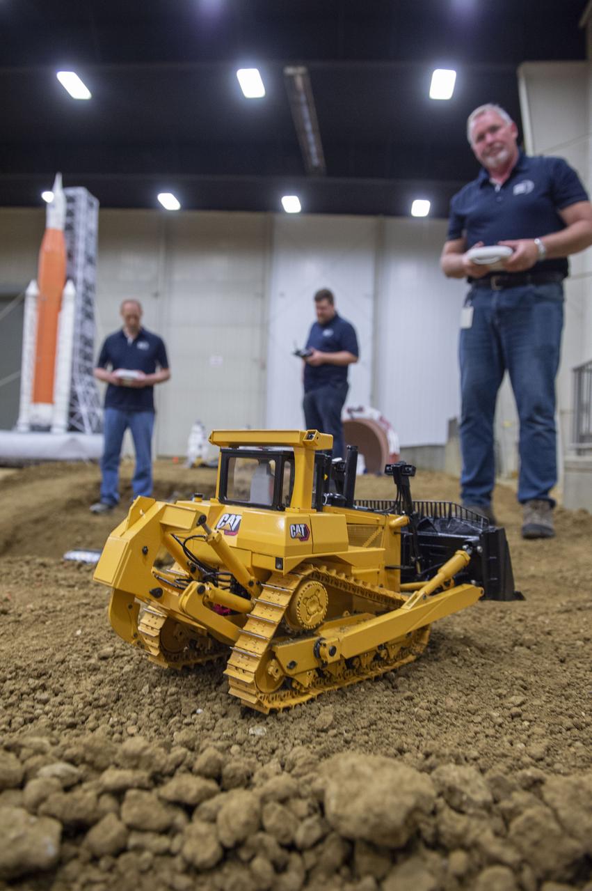
AI. SpaceFactory of New York and Pennsylvania State University of College Park print subscale habitat structures at NASA's 3D-Printed Habitat Challenge, held at the Caterpillar Edwards Demonstration & Learning Center in Edwards, Illinois, May 1-4, 2019. The habitat print is the final level of the multi-phase competition, which began in in 2015. The challenge is managed by NASA's Centennial Challenges program, and partner Bradley University of Peoria, Illinois. Caterpillar engineers work with specially modified radio controlled scale models that accurately replicate moves of full scale caterpillar equipment.
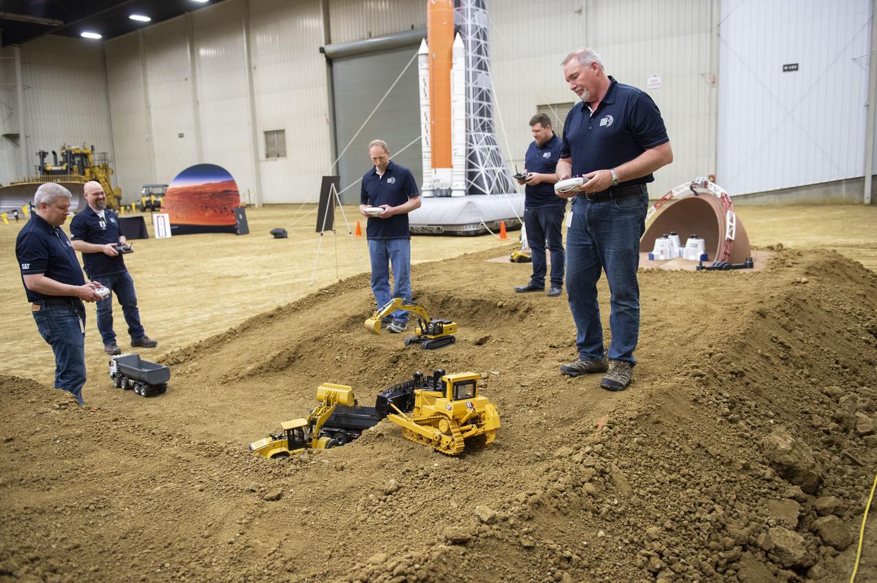
AI. SpaceFactory of New York and Pennsylvania State University of College Park print subscale habitat structures at NASA's 3D-Printed Habitat Challenge, held at the Caterpillar Edwards Demonstration & Learning Center in Edwards, Illinois, May 1-4, 2019. The habitat print is the final level of the multi-phase competition, which began in in 2015. The challenge is managed by NASA's Centennial Challenges program, and partner Bradley University of Peoria, Illinois. Caterpillar engineers work with specially modified radio controlled scale models that accurately replicate moves of full scale caterpillar equipment.

AI. SpaceFactory of New York and Pennsylvania State University of College Park print subscale habitat structures at NASA's 3D-Printed Habitat Challenge, held at the Caterpillar Edwards Demonstration & Learning Center in Edwards, Illinois, May 1-4, 2019. The habitat print is the final level of the multi-phase competition, which began in in 2015. The challenge is managed by NASA's Centennial Challenges program, and partner Bradley University of Peoria, Illinois. Caterpillar engineers work with specially modified radio controlled scale models that accurately replicate moves of full scale caterpillar equipment.
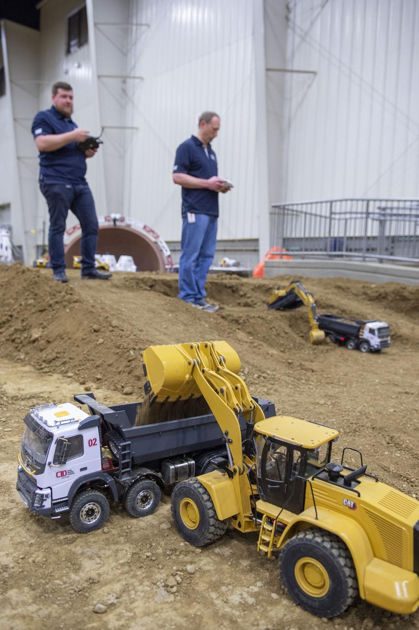
AI. SpaceFactory of New York and Pennsylvania State University of College Park print subscale habitat structures at NASA's 3D-Printed Habitat Challenge, held at the Caterpillar Edwards Demonstration & Learning Center in Edwards, Illinois, May 1-4, 2019. The habitat print is the final level of the multi-phase competition, which began in in 2015. The challenge is managed by NASA's Centennial Challenges program, and partner Bradley University of Peoria, Illinois. Caterpillar engineers work with specially modified radio controlled scale models that accurately replicate moves of full scale caterpillar equipment.
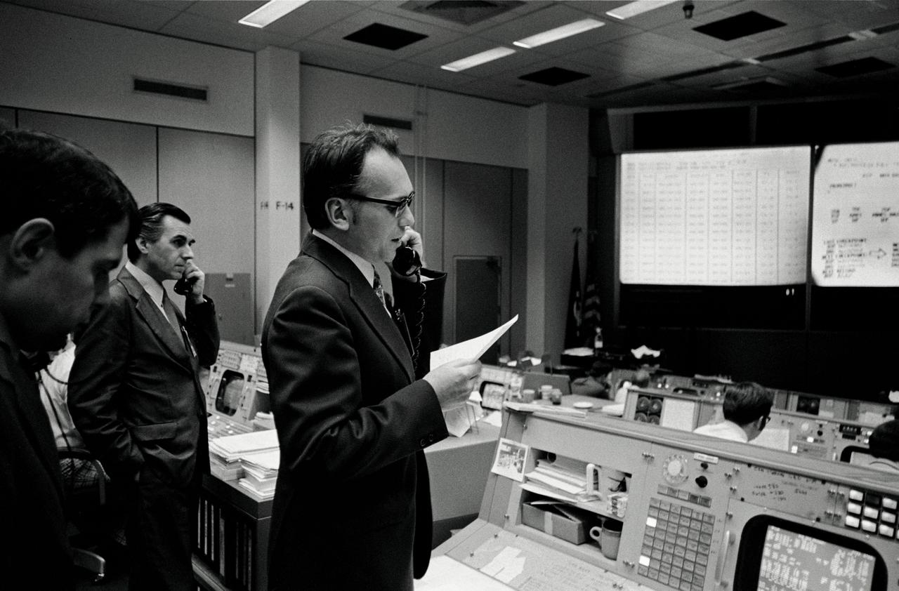
S74-15064 (28 Dec. 1973) --- Dr. Lubos Kohoutek, discoverer of the Comet Kohoutek, is seen in the Mission Operations Control Room in the Mission Control Center during a visit to the Johnson Space Center. He is talking over a radio-telephone with the Skylab 4 crewmen in the Skylab space station in Earth orbit. Professor Kohoutek, a well-known Czechoslovakian astronomer who works at the Hamburg Observatory in West Germany, discussed the comet with astronauts Gerald P. Carr, Edward G. Gibson and William R. Pogue. One of the major objectives of the Skylab 4 mission is to monitor the passing of the Comet Kohoutek. Dr. Zdenek Sekania, who accompanied Dr. Kohoutek on the visit to JSC, is on the telephone in the left background. Dr. Sekania is with the Smithsonian Observatory in Cambridge, Massachusetts. Photo credit: NASA
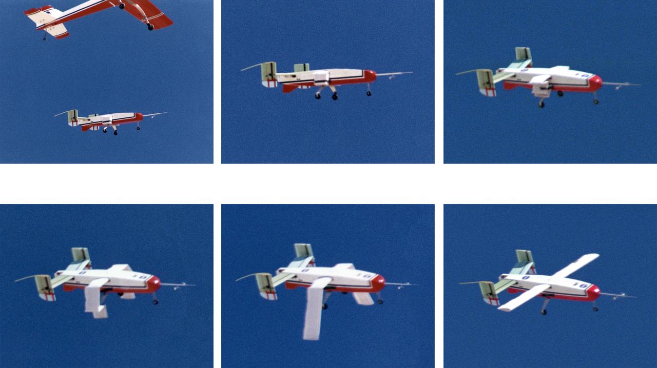
The deployable, inflatable wing technology demonstrator aircraft's wings begin deploying following separation from its carrier aircraft during a flight experiment conducted by the NASA Dryden Flight Research Center, Edwards, California. Wing deployment time is typically on the order of a third of a second, almost faster than the human eye can see. Three successful flights of the I2000 inflatable wing aircraft occurred. During the flights, the team air-launched the radio-controlled (R/C) I2000 from an R/C utility airplane at an altitude of 800-1000 feet. As the I2000 separated from the carrier aircraft, its inflatable wings "popped-out," deploying rapidly via an on-board nitrogen bottle. The aircraft remained stable as it transitioned from wingless to winged flight. The unpowered I2000 glided down to a smooth landing under complete control.
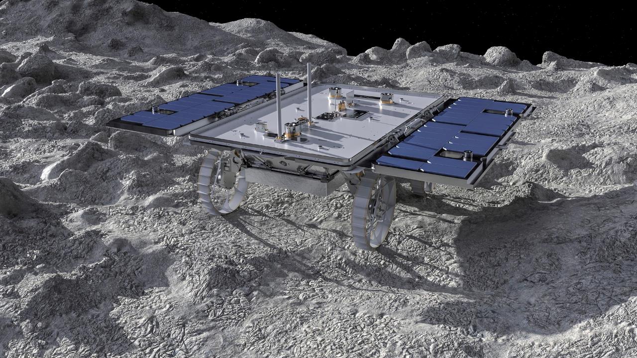
This artist's concept depicts a small rover – part of NASA's CADRE (Cooperative Autonomous Distributed Robotic Exploration) technology demonstration headed for the Moon – on the lunar surface. Motiv Space Systems in Pasadena, California, created the rendering and is collaborating with NASA's Jet Propulsion Laboratory on critical rover and mobility functions. Slated to arrive aboard a lunar lander in 2024 under NASA's CLPS (Commercial Lunar Payload Services) initiative, CADRE is designed to demonstrate that multiple robots can cooperate and explore together autonomously – without direct input from human mission controllers. A trio of the miniature solar-powered rovers, each about the size of a carry-on suitcase, will explore the Moon as a team, communicating via radio with each other and a base station aboard a lunar lander. By taking simultaneous measurements from multiple locations, CADRE will also demonstrate how multirobot missions can record data impossible for a single robot to achieve – a tantalizing prospect for future missions. Motiv contributed subsystems and hardware elements for three of four CADRE systems, including designing and building the mobility system and rover chassis, the base station, the rover deployers, and the motor controller boards. The company also procured and tested the actuators with the flight motor controller boards. https://photojournal.jpl.nasa.gov/catalog/PIA26161
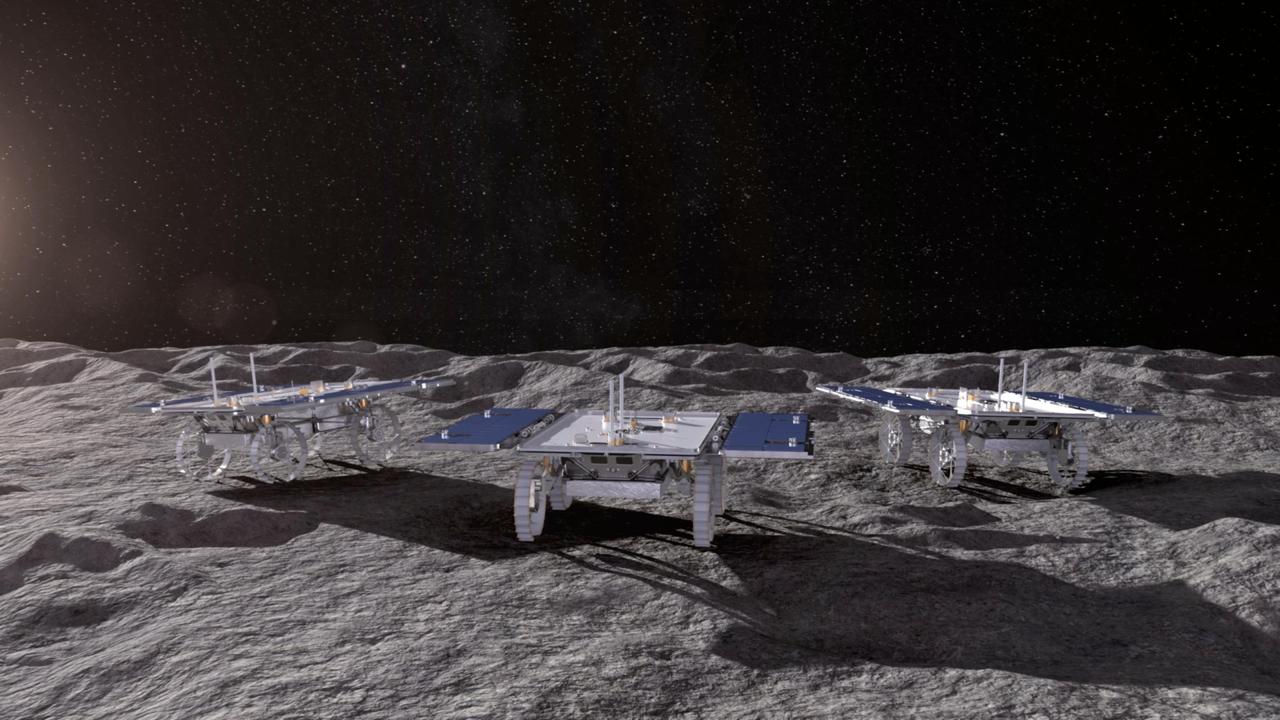
This animated artist's concept depicts three small rovers – part of NASA's CADRE (Cooperative Autonomous Distributed Robotic Exploration) technology demonstration headed for the Moon – driving together on the lunar surface. Motiv Space Systems in Pasadena, California, created the rendering and collaborated with NASA's Jet Propulsion Laboratory on critical rover and mobility functions. Slated to arrive aboard a lunar lander at the Reiner Gamma region of the Moon under NASA's CLPS (Commercial Lunar Payload Services) initiative, CADRE is designed to demonstrate that multiple robots can cooperate and explore together autonomously – without direct input from human mission controllers. A trio of the miniature solar-powered rovers, each about the size of a carry-on suitcase, will explore the Moon as a team, communicating via radio with each other and a base station aboard the lander. By taking simultaneous measurements from multiple locations, CADRE will also demonstrate how multirobot missions can record data impossible for a single robot to achieve – a tantalizing prospect for future missions. Motiv contributed subsystems and hardware elements for three of four CADRE systems, including designing and building the mobility system and rover chassis, the base station, the rover deployers, and the motor controller boards. The company also procured and tested the actuators with the flight motor controller boards. Animation available at https://photojournal.jpl.nasa.gov/catalog/PIA26296

KENNEDY SPACE CENTER, FLA. -- United Space Alliance workers on board the Freedom Star, one of the Shuttle Rocket Booster retrieval ships, check the controls on the recompression chamber at right. The ship and its dive team, including a diver medical technician, Andy Fish, were instrumental in rescuing a lobster diver in distress off Cape Canaveral Sept. 11. The ship was on a certification exercise and near the location of a lobster diving boat that radioed the U.S. Coast Guard for help when one of the divers experienced difficulty breathing on his return to the surface. Hearing the call for help, the captain of the Freedom Star offered to help. Fish stayed with the diver in the recompression chamber aboard the Freedom Star until the ship reached Port Canaveral where a KSC Occupational Health doctor waited. The diver was stabilized and taken to Florida Hospital.
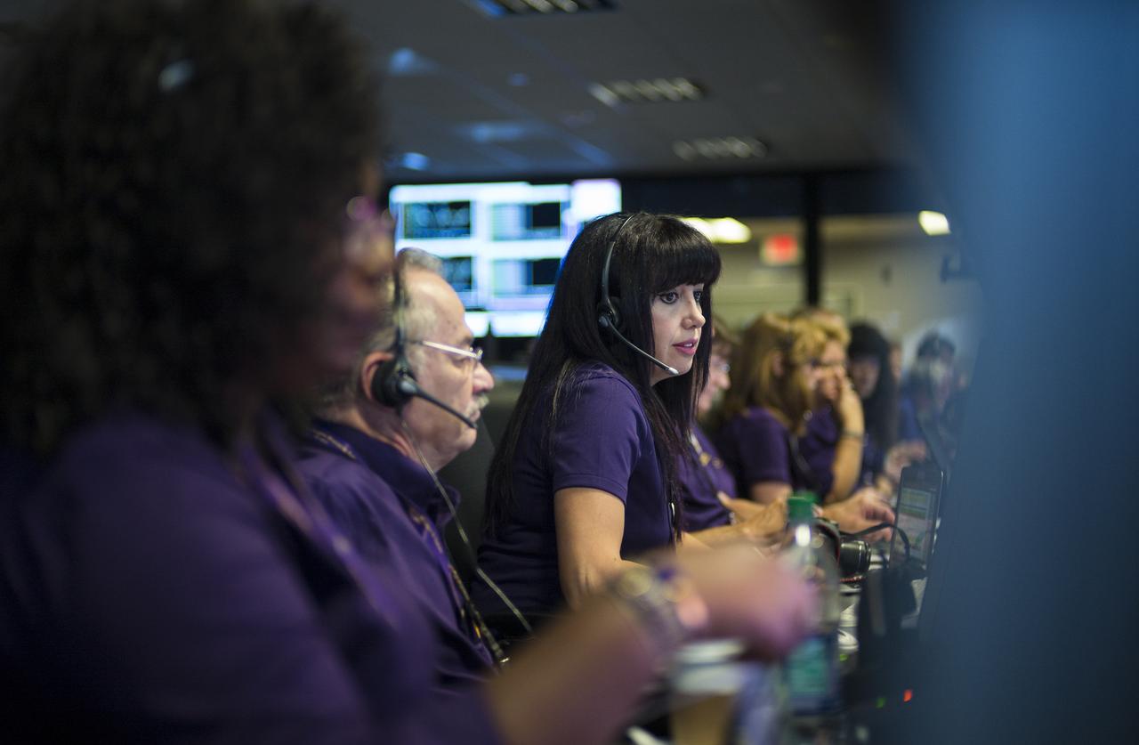
Aseel Anabtawi, of Cassini's radio science team, monitors her console in mission control during Cassini's final plunge into Saturn, Friday, Sept. 15, 2017 at NASA's Jet Propulsion Laboratory in Pasadena, California. Since its arrival in 2004, the Cassini-Huygens mission has been a discovery machine, revolutionizing our knowledge of the Saturn system and captivating us with data and images never before obtained with such detail and clarity. On Sept. 15, 2017, operators deliberately plunged the spacecraft into Saturn, as Cassini gathered science until the end. Loss of contact with the Cassini spacecraft occurred at 7:55 a.m. EDT (4:55 a.m. PDT). The “plunge” ensures Saturn’s moons will remain pristine for future exploration. During Cassini’s final days, mission team members from all around the world gathered at NASA’s Jet Propulsion Laboratory, Pasadena, California, to celebrate the achievements of this historic mission. Photo Credit: (NASA/Joel Kowsky)
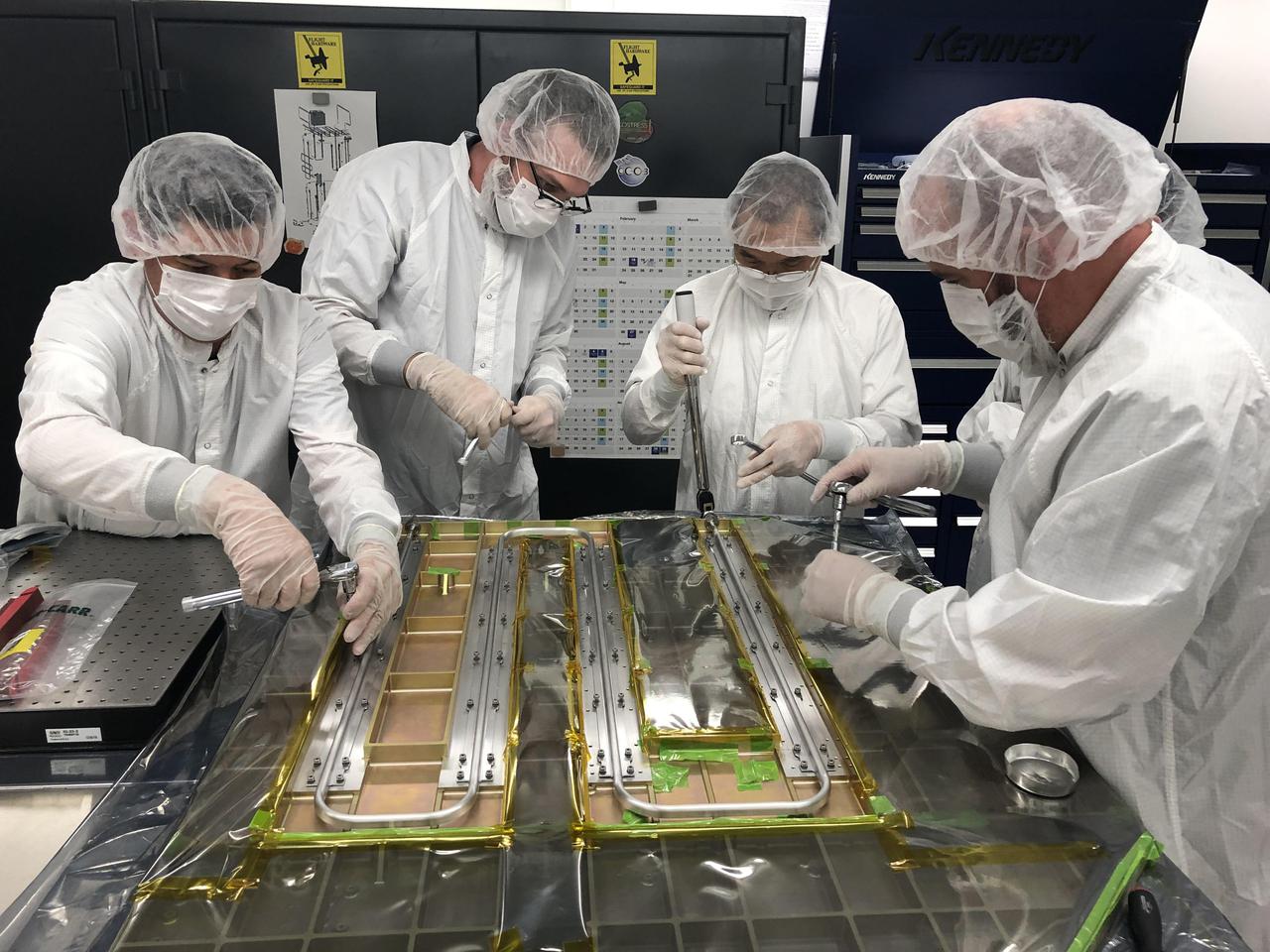
Europa Clipper technicians and engineers at NASA's Jet Propulsion Laboratory in Southern California work together in a cleanroom on Sept. 12, 2019. They bond thermal tubing to the spacecraft's Radio Frequency (RF) panel, which was built by Johns Hopkins University Applied Physics Laboratory (APL) in Laurel, Maryland. The tubing is part of a Heat Redistribution System (HRS) that pumps coolant all around the spacecraft and helps control its temperature as it travels through space. With an internal global ocean twice the size of Earth's oceans combined, Europa may have the potential to harbor life. NASA's Europa Clipper spacecraft will swoop around Jupiter on an elliptical path, dipping close to the moon on each flyby to collect data. Understanding Europa's habitability will help scientists better understand how life developed on Earth and the potential for finding life beyond our planet. Europa Clipper is aiming for a launch readiness date of 2024. https://photojournal.jpl.nasa.gov/catalog/PIA24324
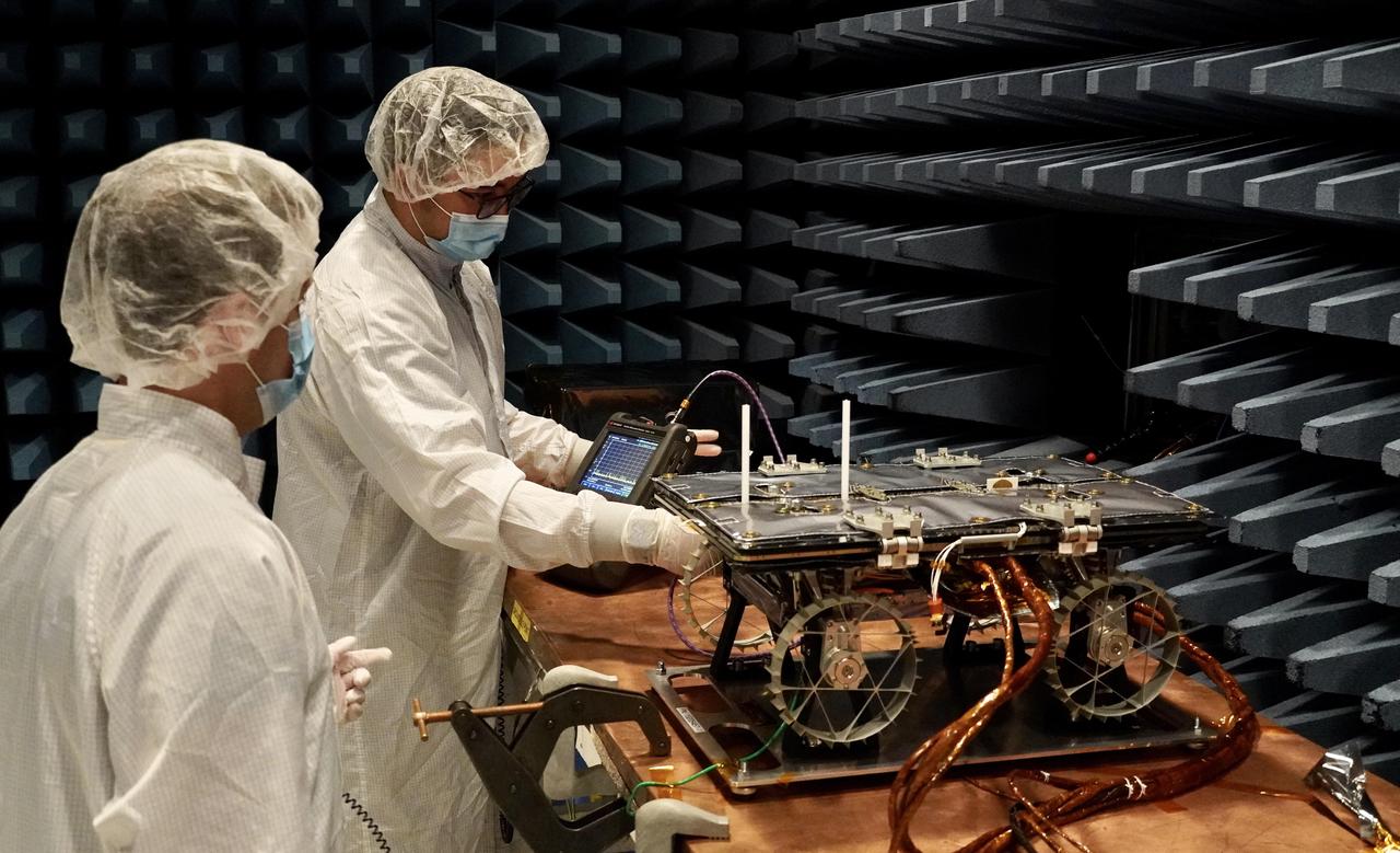
In a special chamber at NASA's Jet Propulsion Laboratory, engineers prepare to test a small rover that will go to the Moon as part of a NASA technology demonstration called CADRE (Cooperative Autonomous Distributed Robotic Exploration). The project is designed to show that a group of robotic spacecraft can work together as a team to accomplish tasks and record data autonomously – without explicit commands from mission controllers on Earth. This electromagnetic interference and compatibility testing took place in November 2023 in a chamber designed to absorb radio waves. Such testing is intended to confirm that the operation of the electronic subsystems do not interfere with each other nor with those on the lander, and that the rover can survive expected electromagnetic disturbances. Justin Schachter, left, and Manny Soriano are shown. https://photojournal.jpl.nasa.gov/catalog/PIA26166
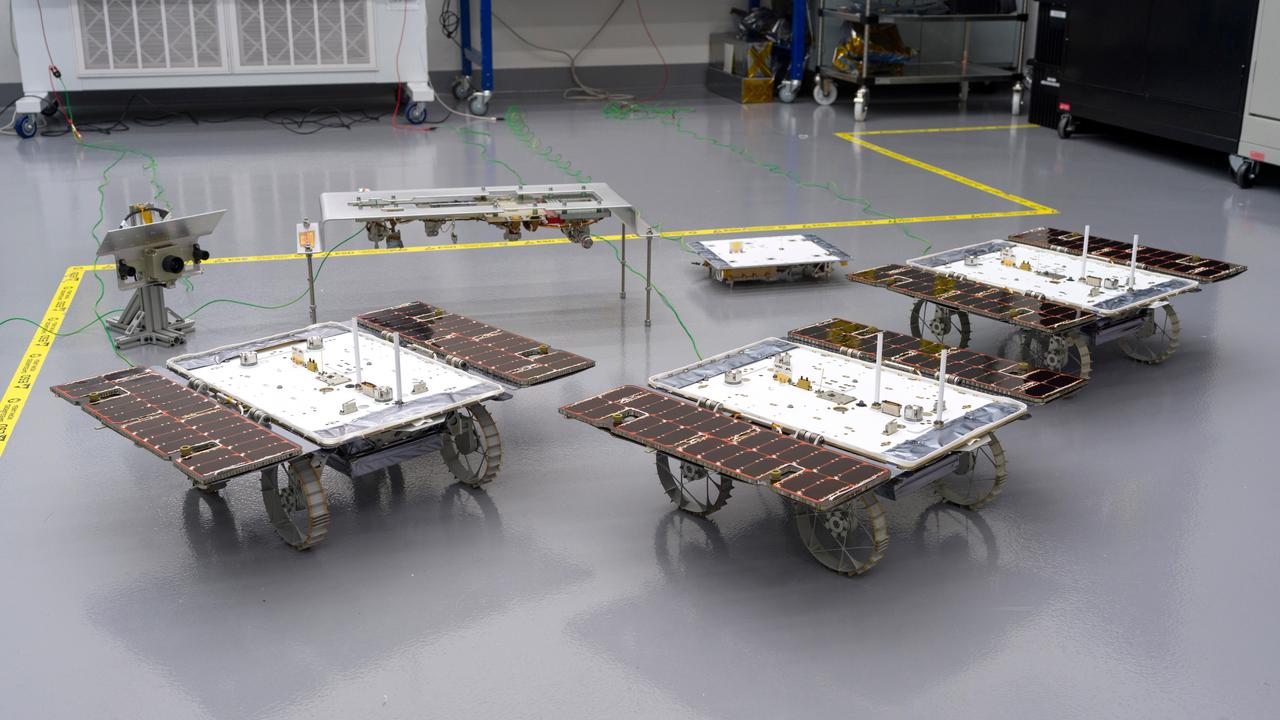
Three small rovers bound for the Moon – part of NASA's CADRE (Cooperative Autonomous Distributed Robotic Exploration) technology demonstration – are arrayed in a clean room at the agency's Jet Propulsion Laboratory in Southern California on Jan. 26, 2024. CADRE is designed to show that a group of robotic spacecraft can work together autonomously as a team to accomplish tasks and record data without constant direction from mission controllers on Earth. Each about the size of a carry-on suitcase, the rovers will ride to the Moon's surface aboard a lander equipped with the hardware elements that sit behind them in this image: from left, the situational awareness camera assembly, one of the deployers that will lower the rovers onto the lunar surface, and the base station with which the rovers will communicate via mesh network radios. https://photojournal.jpl.nasa.gov/catalog/PIA26346

Aseel Anabtawi, of Cassini's radio science team, monitors her console in mission control during Cassini's final plunge into Saturn, Friday, Sept. 15, 2017 at NASA's Jet Propulsion Laboratory in Pasadena, California. Since its arrival in 2004, the Cassini-Huygens mission has been a discovery machine, revolutionizing our knowledge of the Saturn system and captivating us with data and images never before obtained with such detail and clarity. On Sept. 15, 2017, operators deliberately plunged the spacecraft into Saturn, as Cassini gathered science until the end. Loss of contact with the Cassini spacecraft occurred at 7:55 a.m. EDT (4:55 a.m. PDT). The “plunge” ensures Saturn’s moons will remain pristine for future exploration. During Cassini’s final days, mission team members from all around the world gathered at NASA’s Jet Propulsion Laboratory, Pasadena, California, to celebrate the achievements of this historic mission. Photo Credit: (NASA/Joel Kowsky)
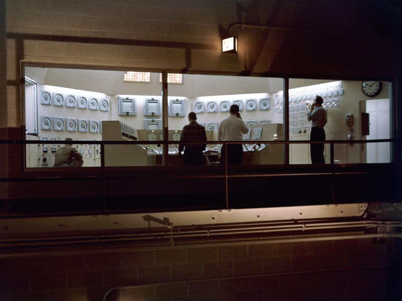
Operators test the National Aeronautics and Space Administration’s (NASA) Plum Brook Reactor Facility systems in the months leading up to its actual operation. The “Reactor On” signs are illuminated but the reactor core was not yet ready for chain reactions. Just a couple weeks after this photograph, Plum Brook Station held a media open house to unveil the 60-megawatt test reactor near Sandusky, Ohio. More than 60 members of the print media and radio and television news services met at the site to talk with community leaders and representatives from NASA and Atomic Energy Commission. The Plum Brook reactor went critical for the first time on the evening of June 14, 1961. It was not until April 1963 that the reactor reached its full potential of 60 megawatts. The reactor control room, located on the second floor of the facility, was run by licensed operators. The operators manually operated the shim rods which adjusted the chain reaction in the reactor core. The regulating rods could partially or completely shut down the reactor. The control room also housed remote area monitoring panels and other monitoring equipment that allowed operators to monitor radiation sensors located throughout the facility and to scram the reactor instantly if necessary. The color of the indicator lights corresponded with the elevation of the detectors in the various buildings. The reactor could also shut itself down automatically if the monitors detected any sudden irregularities.
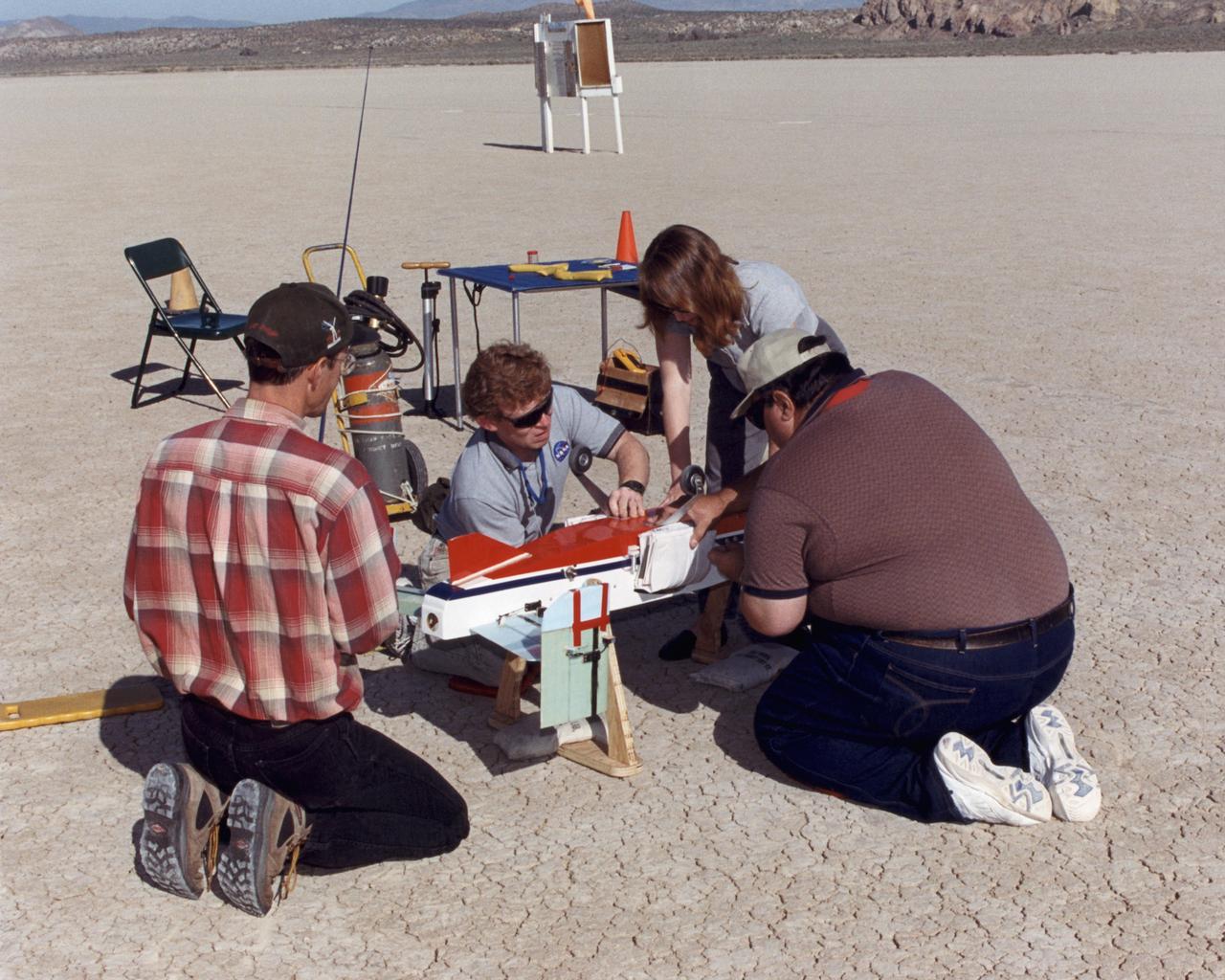
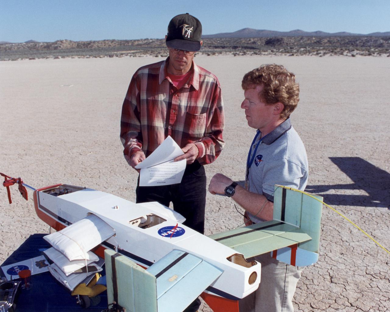
Dryden Model Shop's Tony Frakowiak remotely flies an experimental model aircraft being powered by a spotlight operated by Dryden aerospace engineer (code RA) Ryan Warner.
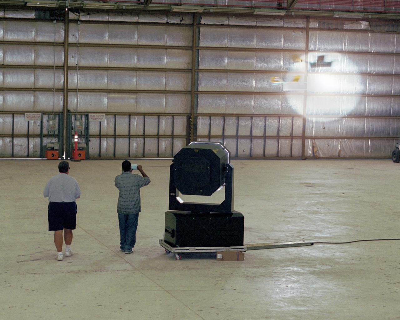
Dryden Model Shop's Tony Frakowiak remotely flies an experimental model aircraft being powered by a spotlight operated by student intern Derrick Barrett.
Powered by a laser beam directed at it from a center pedestal, a lightweight model plane makes the first flight of an aircraft powered by laser energy inside a building at NASA's Marshall Space Flight Center.
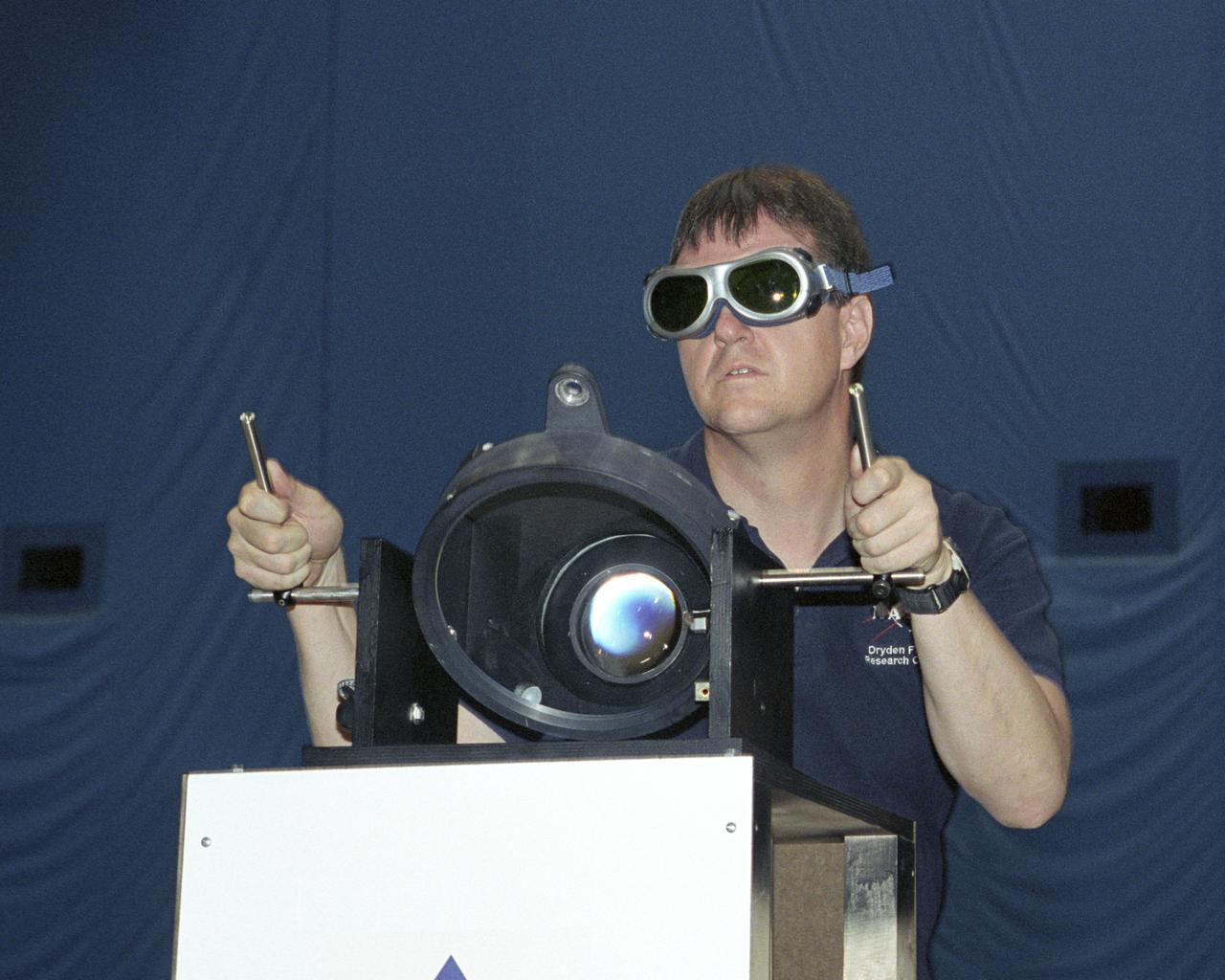
NASA Dryden project engineer Dave Bushman carefully aims the optics of a laser device at a solar cell panel on a model aircraft during the first flight demonstration of an aircraft powered by laser light.
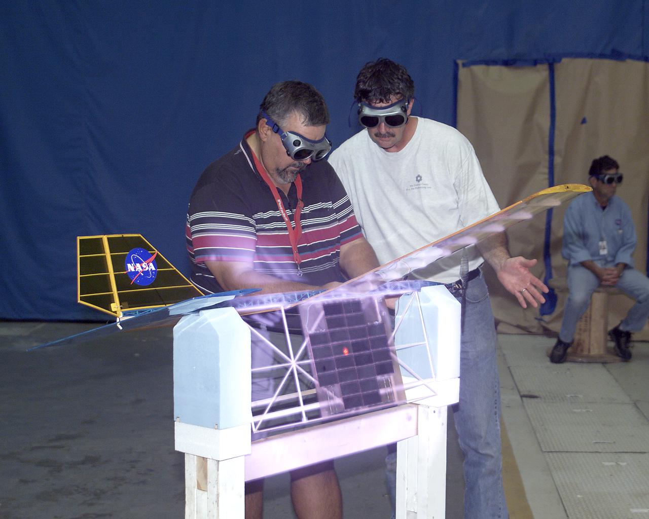
With a laser beam centered on its solar panel, a lightweight model aircraft is checked out by technician Tony Frakowiak and researcher Tim Blackwell before its power-beamed demonstration flight.
With a laser beam centered on its panel of photovoltaic cells, a lightweight model plane makes the first flight of an aircraft powered by a laser beam inside a building at NASA Marshall Space Flight Center.
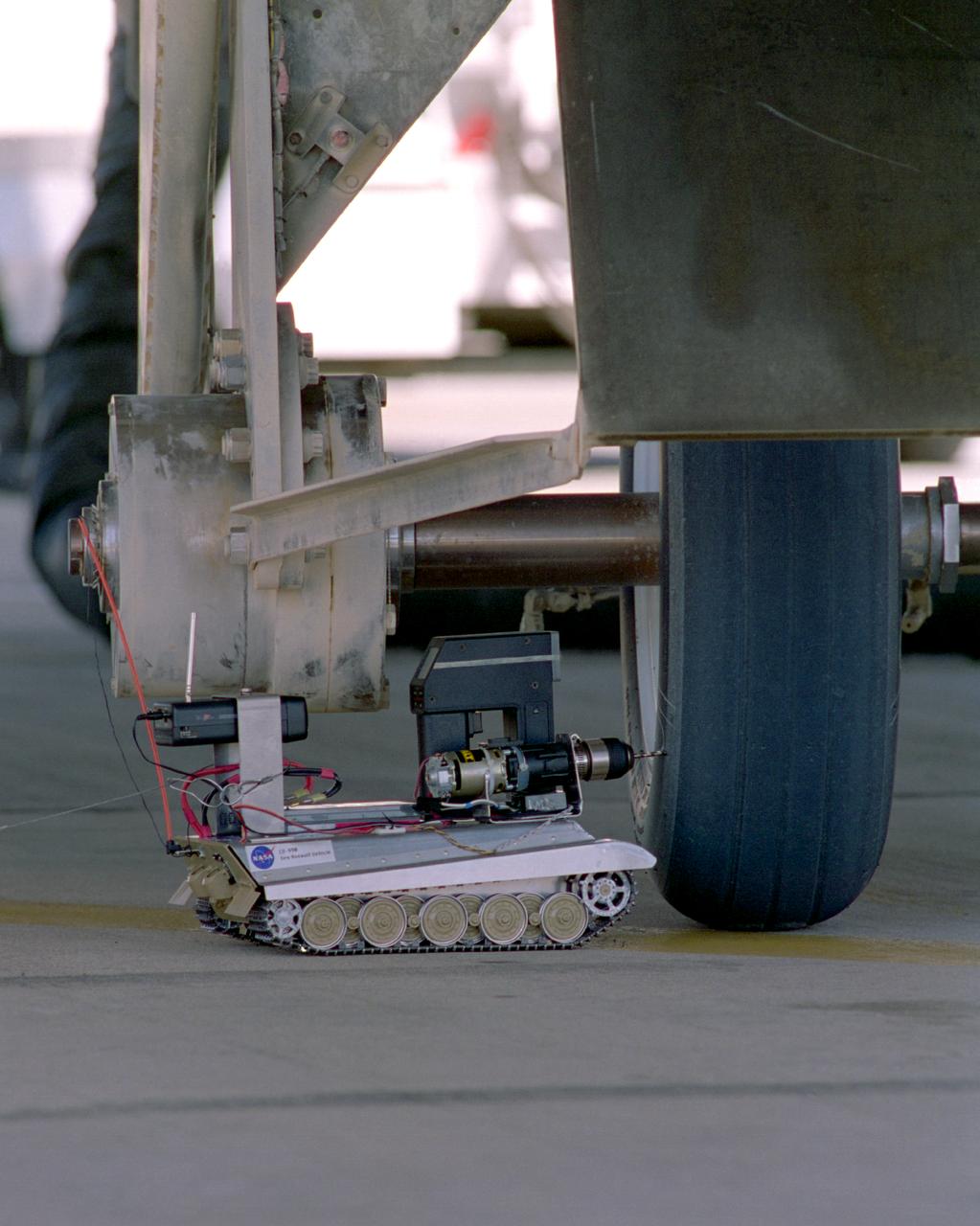
Created from a 1/16th model of a German World War II tank, the TAV (Tire Assault Vehicle) was an important safety feature for the Convair 990 Landing System Research Aircraft, which tested space shuttle tires. It was imperative to know the extreme conditions the shuttle tires could tolerate at landing without putting the shuttle and its crew at risk. In addition, the CV990 was able to land repeatedly to test the tires. The TAV was built from a kit and modified into a radio controlled, video-equipped machine to drill holes in aircraft test tires that were in imminent danger of exploding because of one or more conditions: high air pressure, high temperatures, and cord wear. An exploding test tire releases energy equivalent to two and one-half sticks of dynamite and can cause severe injuries to anyone within 50 ft. of the explosion, as well as ear injury - possibly permanent hearing loss - to anyone within 100 ft. The degree of danger is also determined by the temperature pressure and cord wear of a test tire. The TAV was developed by David Carrott, a PRC employee under contract to NASA.
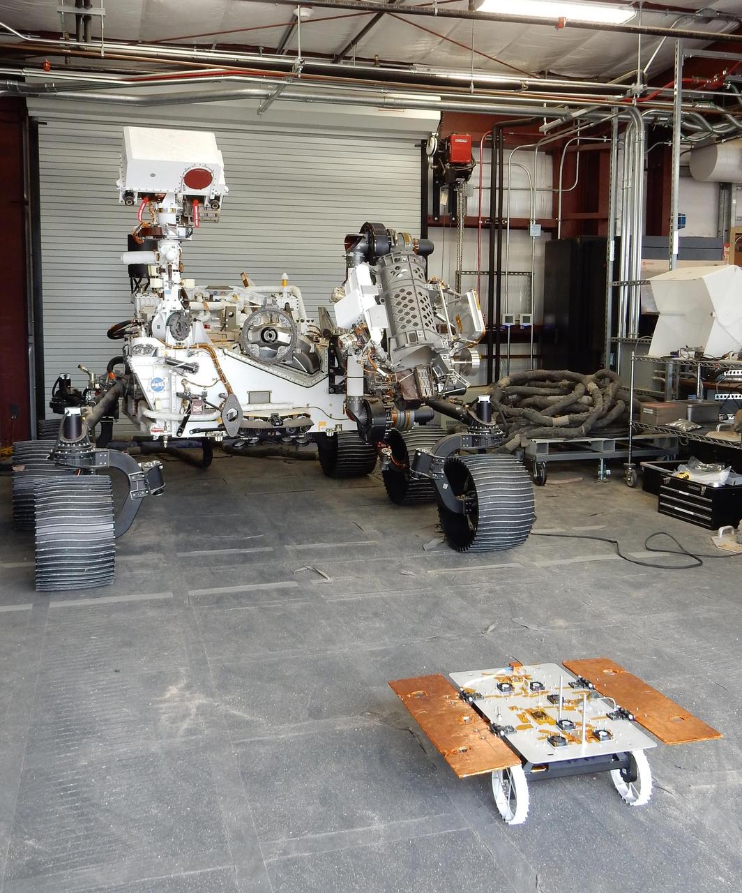
The Earth-bound full-scale engineering model of NASA's Perseverance rover, called OPTIMISM, seems to peer down at a much smaller CADRE rover in a building in the Mars Yard at NASA's Jet Propulsion Laboratory in Southern California in June 2023. Short for Cooperative Autonomous Distributed Robotic Exploration, NASA's CADRE technology demonstration is slated to arrive at the Moon in spring 2024 as part of the agency's CLPS (Commercial Lunar Payload Services) initiative. CADRE is designed to demonstrate that multiple robots can cooperate and explore together autonomously – without direct input from human mission controllers. The development rover being tested is similar in size and appearance to the flight models of the CADRE rovers, which are still being built. A trio of the miniature solar-powered rovers, each about the size of a carry-on suitcase, will explore the Moon as a team, communicating via radio with each other and a base station aboard a lunar lander. By taking simultaneous measurements from multiple locations, CADRE will also demonstrate how multirobot missions can record data impossible for a single robot to achieve – a tantalizing prospect for future missions. https://photojournal.jpl.nasa.gov/catalog/PIA25668
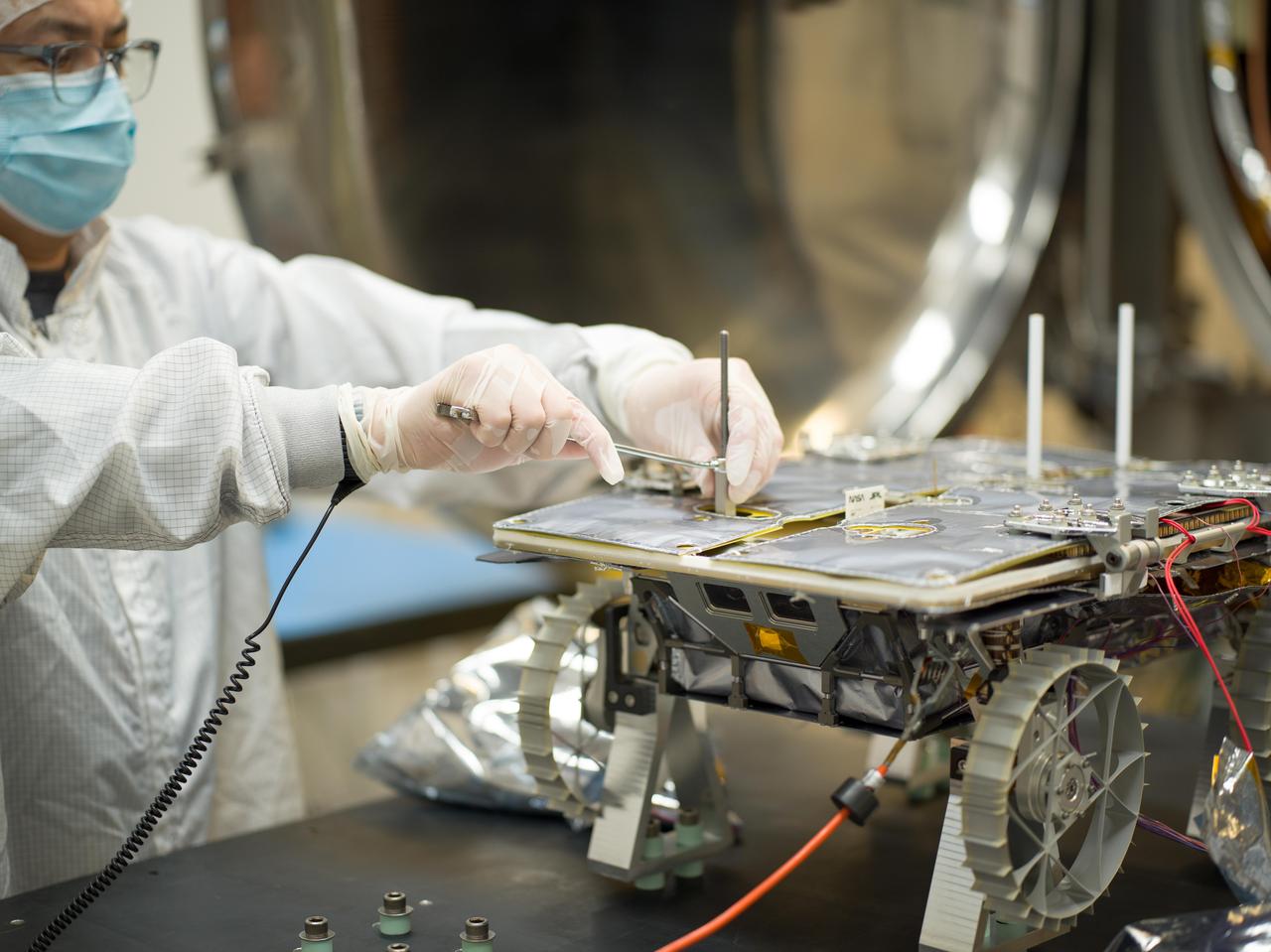
An engineer prepares a small rover – part of NASA's CADRE (Cooperative Autonomous Distributed Robotic Exploration) technology demonstration that's headed to the Moon – for testing in a thermal vacuum chamber at the agency's Jet Propulsion Laboratory in Southern California in October 2023. Slated to arrive at the Moon in 2024 as part of NASA's CLPS (Commercial Lunar Payload Services) initiative, CADRE is designed to demonstrate that multiple robots can cooperate and explore together autonomously – without direct input from human mission controllers. A trio of the miniature solar-powered rovers, each about the size of a carry-on suitcase, will explore the Moon as a team, communicating via radio with each other and a base station aboard a lunar lander. By taking simultaneous measurements from multiple locations, CADRE will also demonstrate how multirobot missions can record data impossible for a single robot to achieve – a tantalizing prospect for future missions. The rover being tested is the first flight model to be completed. Thermal vacuum testing simulates the harsh environment the rovers will face on the journey to the Moon and on the lunar surface: All the air is pumped out of the chamber and the temperature is cycled to high and low extremes. https://photojournal.jpl.nasa.gov/catalog/PIA25669
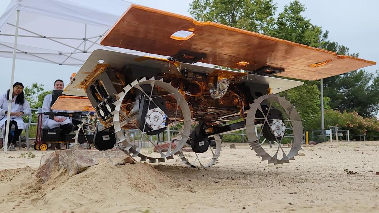
A development rover that is part of NASA's CADRE (Cooperative Autonomous Distributed Robotic Exploration) technology demonstration drives over a rock during its first autonomous drive around the Mars Yard at the agency's Jet Propulsion Laboratory in Southern California in June 2023. Under a canopy behind the rover are, from left, graduate student intern Natalie Deo and CADRE verification and validation lead Sawyer Brooks of JPL. The CADRE team successfully tested a new wheel design, surface navigation software, and mobility capabilities, among other aspects of the project. The rover being tested is similar in size and appearance to the flight models of the CADRE rovers, which are still being built. Slated to arrive at the Moon in spring 2024 as part of NASA's CLPS (Commercial Lunar Payload Services) initiative, CADRE is designed to demonstrate that multiple robots can cooperate and explore together autonomously – without direct input from human mission controllers. A trio of the miniature solar-powered rovers, each about the size of a carry-on suitcase, will explore the Moon as a team, communicating via radio with each other and a base station aboard a lunar lander. By taking simultaneous measurements from multiple locations, CADRE will also demonstrate how multirobot missions can record data impossible for a single robot to achieve – a tantalizing prospect for future missions. Movie available at https://photojournal.jpl.nasa.gov/catalog/PIA25667

A development model rover that is part of NASA's CADRE (Cooperative Autonomous Distributed Robotic Exploration) technology demonstration took its first autonomous drive around the Mars Yard at the agency's Jet Propulsion Laboratory in Southern California in June 2023. The CADRE team tested a new wheel design, surface navigation software, and mobility capabilities, among other aspects of the project. Engineer Kristopher Sherrill is shown recording video of the test. The rover being tested is similar in size and appearance to the flight models of the CADRE rovers, which are still being built. Slated to arrive at the Moon in spring 2024 as part of NASA's CLPS (Commercial Lunar Payload Services) initiative, CADRE is designed to demonstrate that multiple robots can cooperate and explore together autonomously – without direct input from human mission controllers. A trio of the miniature solar-powered rovers, each about the size of a carry-on suitcase, will explore the Moon as a team, communicating via radio with each other and a base station aboard a lunar lander. By taking simultaneous measurements from multiple locations, CADRE will also demonstrate how multirobot missions can record data impossible for a single robot to achieve – a tantalizing prospect for future missions. Movie available at https://photojournal.jpl.nasa.gov/catalog/PIA25665
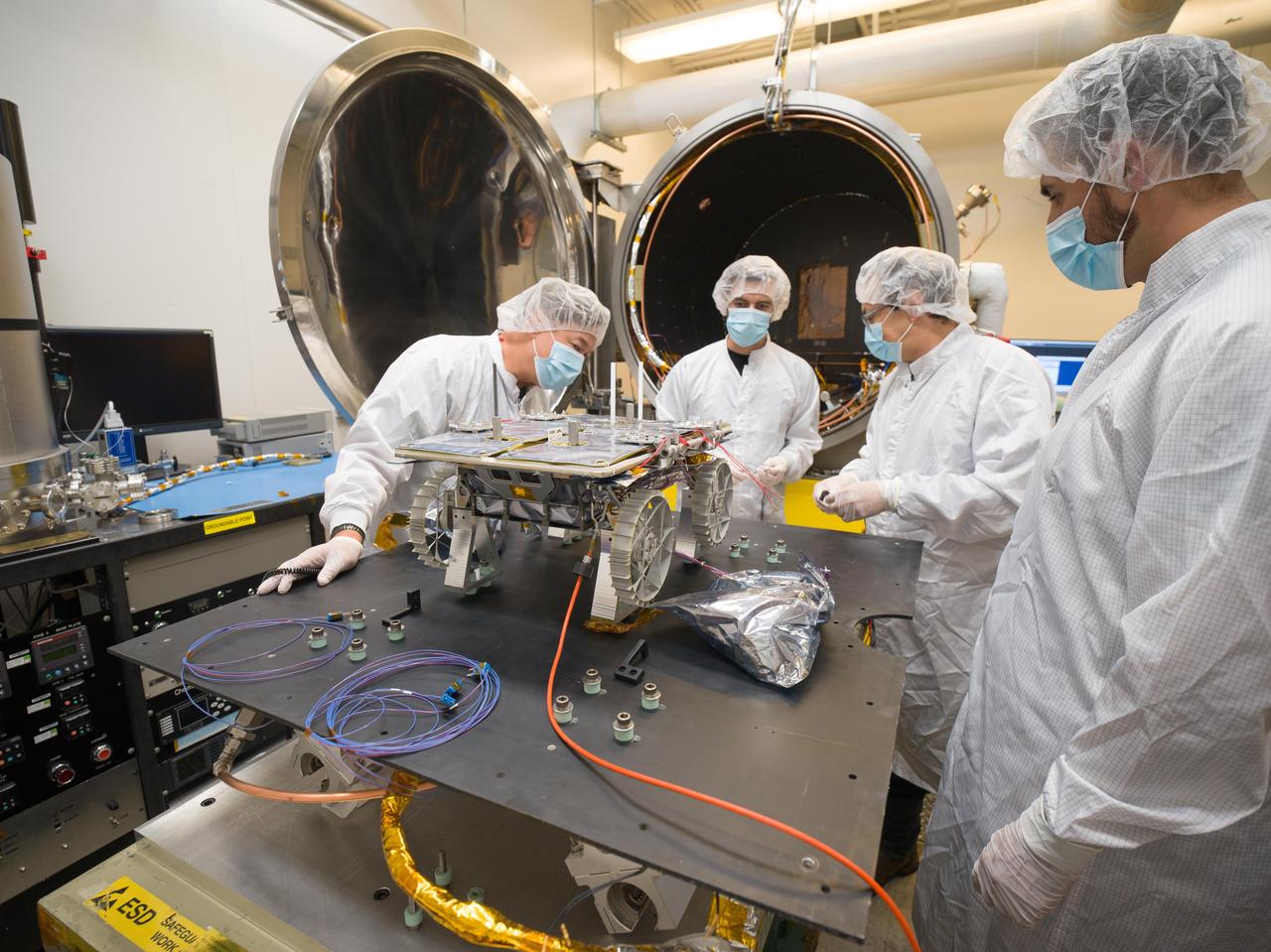
Engineers prepare a small rover – part of NASA's CADRE (Cooperative Autonomous Distributed Robotic Exploration) technology demonstration that's headed to the Moon – for testing in the thermal vacuum chamber behind them at the agency's Jet Propulsion Laboratory in Southern California in October 2023. Slated to arrive at the Moon in 2024 as part of NASA's CLPS (Commercial Lunar Payload Services) initiative, CADRE is designed to demonstrate that multiple robots can cooperate and explore together autonomously – without direct input from human mission controllers. A trio of the miniature solar-powered rovers, each about the size of a carry-on suitcase, will explore the Moon as a team, communicating via radio with each other and a base station aboard a lunar lander. By taking simultaneous measurements from multiple locations, CADRE will also demonstrate how multirobot missions can record data impossible for a single robot to achieve – a tantalizing prospect for future missions. The rover being tested is the first flight model to be completed. Thermal vacuum testing simulates the harsh environment the rovers will face on the journey to the Moon and on the lunar surface: All the air is pumped out of the chamber and the temperature is cycled to high and low extremes. https://photojournal.jpl.nasa.gov/catalog/PIA25670
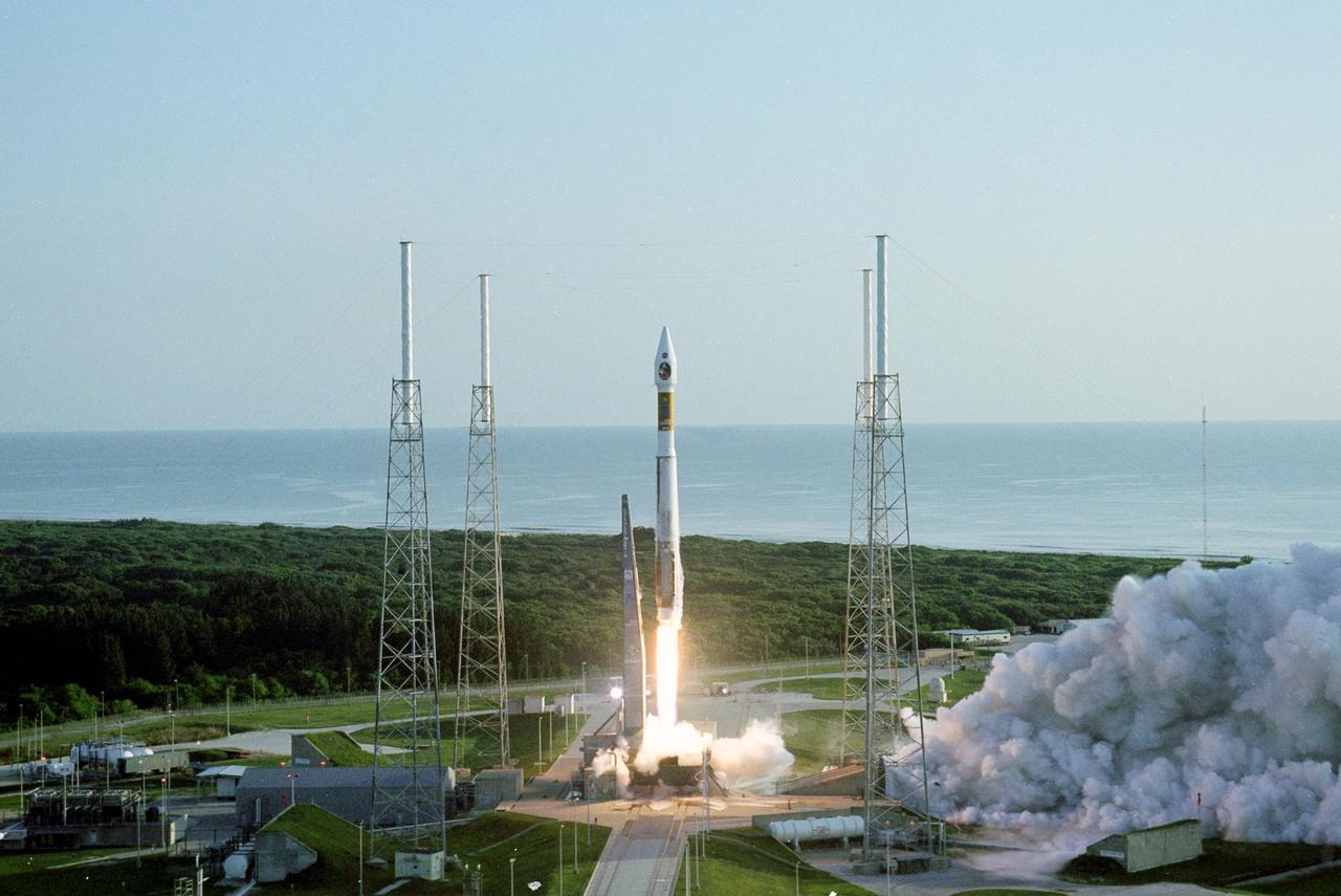
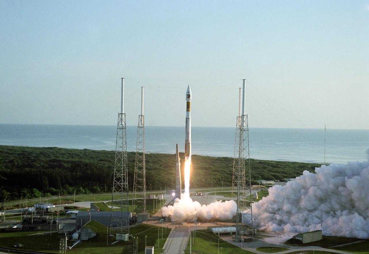
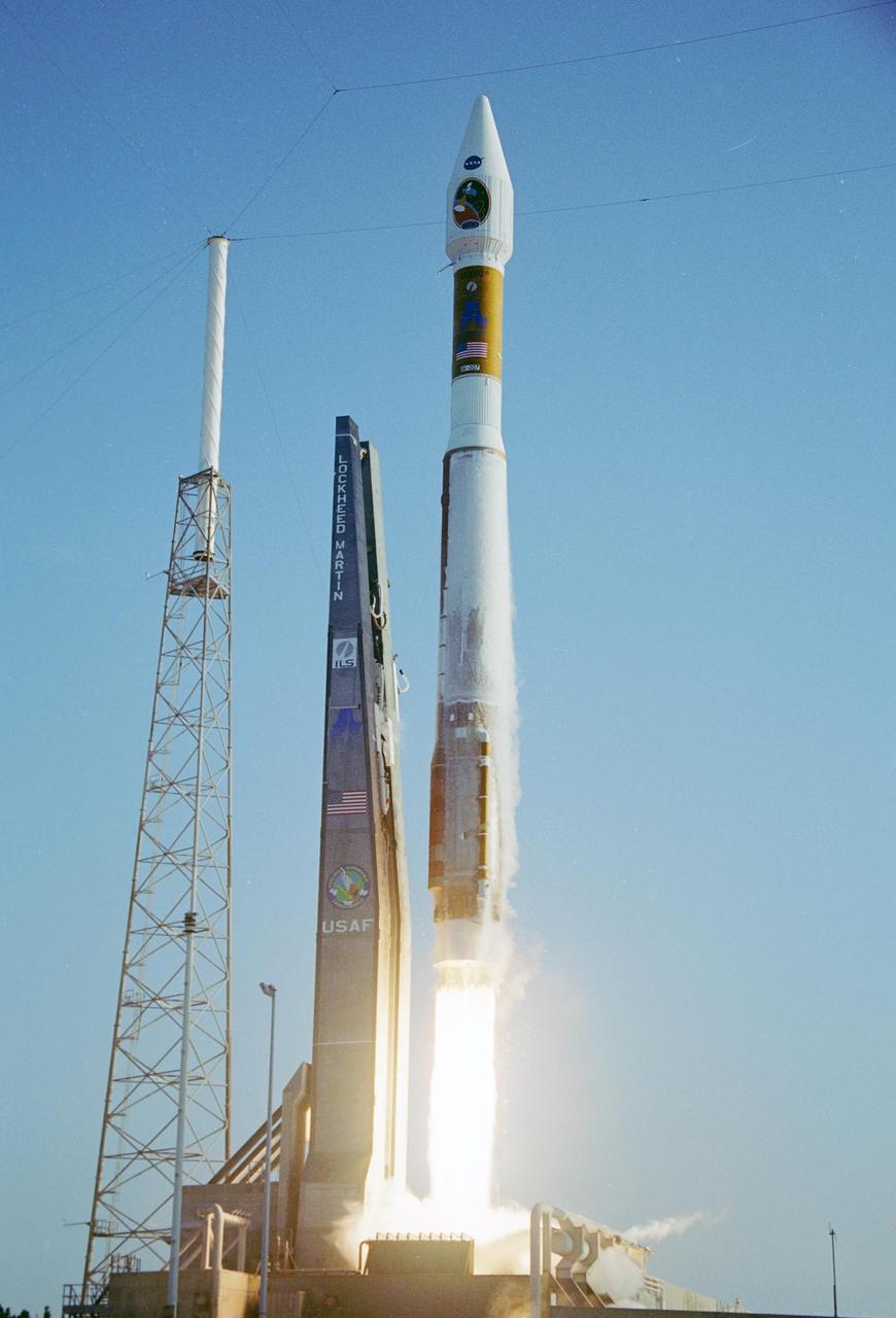
KENNEDY SPACE CENTER, FLA. - With the Atlantic Ocean as a backdrop, an Atlas V launch vehicle, 19 stories tall, with a two-ton Mars Reconnaissance Orbiter (MRO) on top, roars away from Launch Complex 41 at Cape Canaveral Air Force Station at 7:43 a.m. EDT. All systems performed nominally for NASA's first launch of an Atlas V on an interplanetary mission. MRO established radio contact with controllers 61 minutes after launch and within four minutes of separation from the upper stage. Initial contact came through an antenna at the Japan Aerospace Exploration Agency's Uchinoura Space Center in southern Japan. Mars is 72 million miles from Earth today, but the spacecraft will travel more than four times that distance on its outbound-arc trajectory to intercept the red planet on March 10, 2006. The orbiter carries six scientific instruments for examining the surface, atmosphere and subsurface of Mars in unprecedented detail from low orbit. NASA expects to get several times more data about Mars from MRO than from all previous Martian missions combined. Researchers will use the instruments to learn more about the history and distribution of Mars' water. That information will improve understanding of planetary climate change and will help guide the quest to answer whether Mars ever supported life. The orbiter will also evaluate potential landing sites for future missions. (Photo Credit: Pat Corkery/Lockheed Martin)
KENNEDY SPACE CENTER, FLA. - With the Atlantic Ocean as a backdrop, an Atlas V launch vehicle, 19 stories tall, with a two-ton Mars Reconnaissance Orbiter (MRO) on top, roars away from Launch Complex 41 at Cape Canaveral Air Force Station at 7:43 a.m. EDT. All systems performed nominally for NASA's first launch of an Atlas V on an interplanetary mission. MRO established radio contact with controllers 61 minutes after launch and within four minutes of separation from the upper stage. Initial contact came through an antenna at the Japan Aerospace Exploration Agency's Uchinoura Space Center in southern Japan. Mars is 72 million miles from Earth today, but the spacecraft will travel more than four times that distance on its outbound-arc trajectory to intercept the red planet on March 10, 2006. The orbiter carries six scientific instruments for examining the surface, atmosphere and subsurface of Mars in unprecedented detail from low orbit. NASA expects to get several times more data about Mars from MRO than from all previous Martian missions combined. Researchers will use the instruments to learn more about the history and distribution of Mars' water. That information will improve understanding of planetary climate change and will help guide the quest to answer whether Mars ever supported life. The orbiter will also evaluate potential landing sites for future missions. (Photo Credit: Pat Corkery/Lockheed Martin)
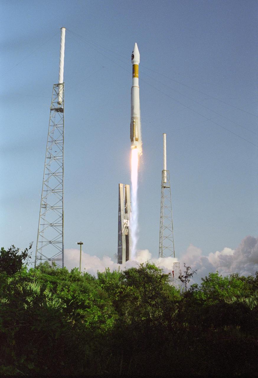
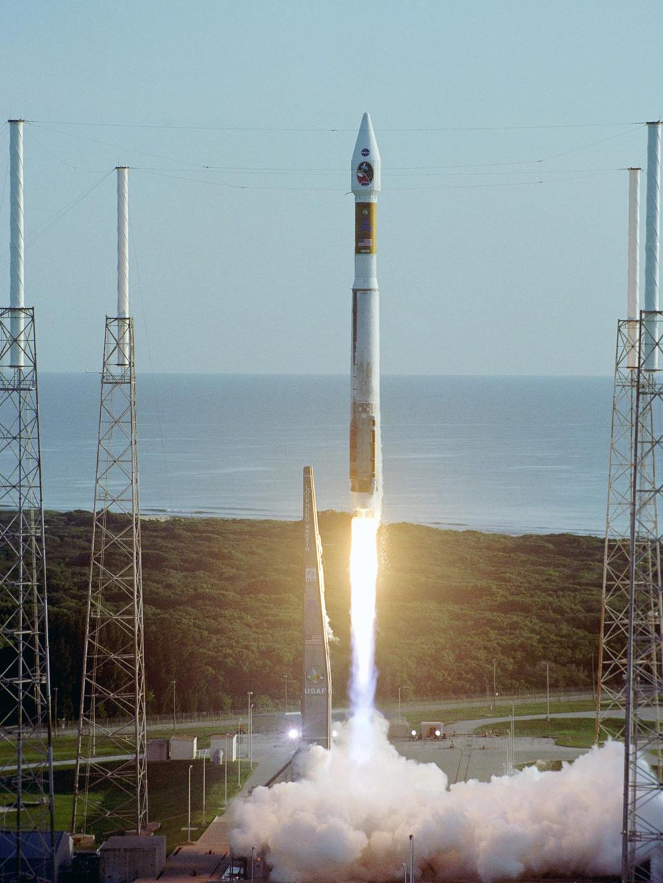
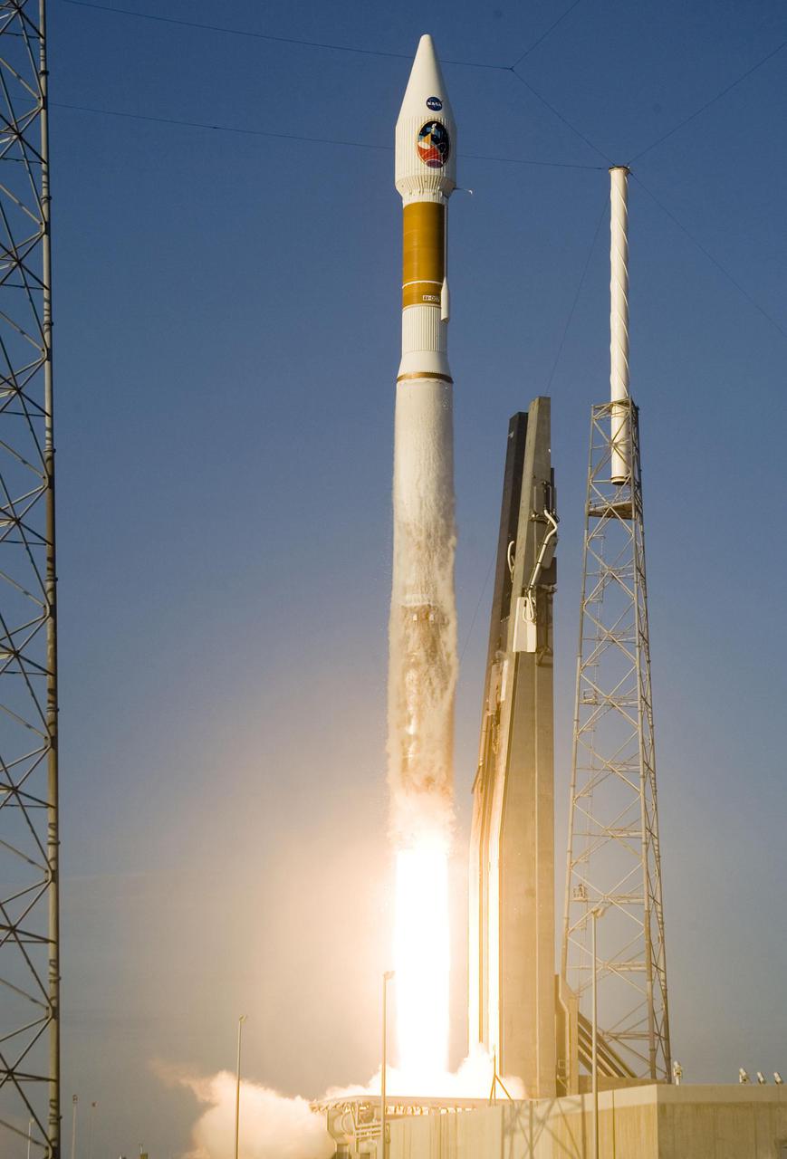
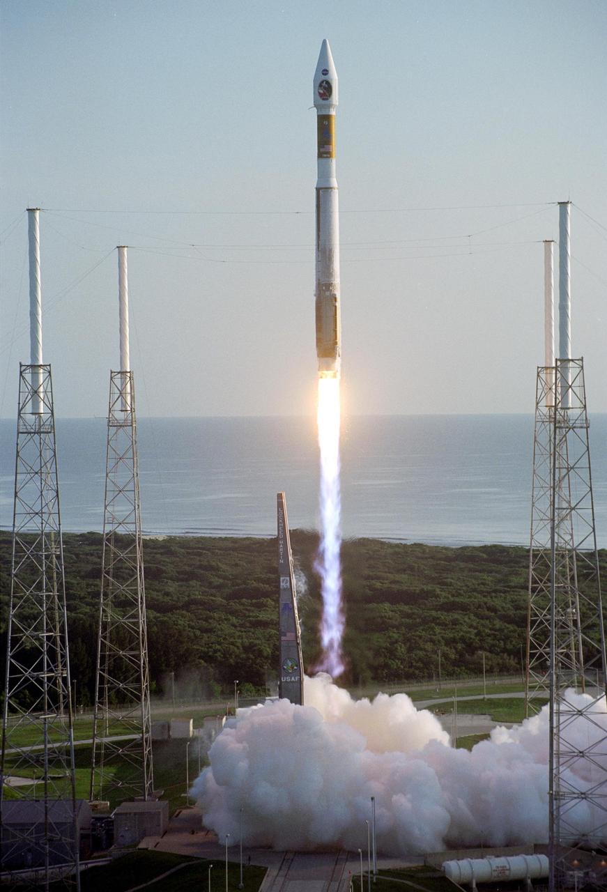
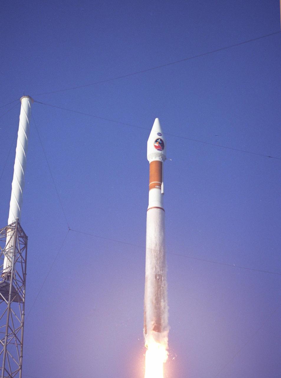
KENNEDY SPACE CENTER, FLA. - The 19-stories-tall Atlas V launch vehicle leaps above the trees near Launch Complex 41 at Cape Canaveral Air Force Station in Florida, propelling the two-ton Mars Reconnaissance Orbiter (MRO) into a clear blue Florida sky and eventual orbit around Mars. Liftoff was at 7:43 a.m. EDT. All systems performed nominally for NASA's first launch of an Atlas V on an interplanetary mission. MRO established radio contact with controllers 61 minutes after launch and within four minutes of separation from the upper stage. Initial contact came through an antenna at the Japan Aerospace Exploration Agency's Uchinoura Space Center in southern Japan. Mars is 72 million miles from Earth today, but the spacecraft will travel more than four times that distance on its outbound-arc trajectory to intercept the red planet on March 10, 2006. The orbiter carries six scientific instruments for examining the surface, atmosphere and subsurface of Mars in unprecedented detail from low orbit. NASA expects to get several times more data about Mars from MRO than from all previous Martian missions combined. Researchers will use the instruments to learn more about the history and distribution of Mars' water. That information will improve understanding of planetary climate change and will help guide the quest to answer whether Mars ever supported life. The orbiter will also evaluate potential landing sites for future missions.
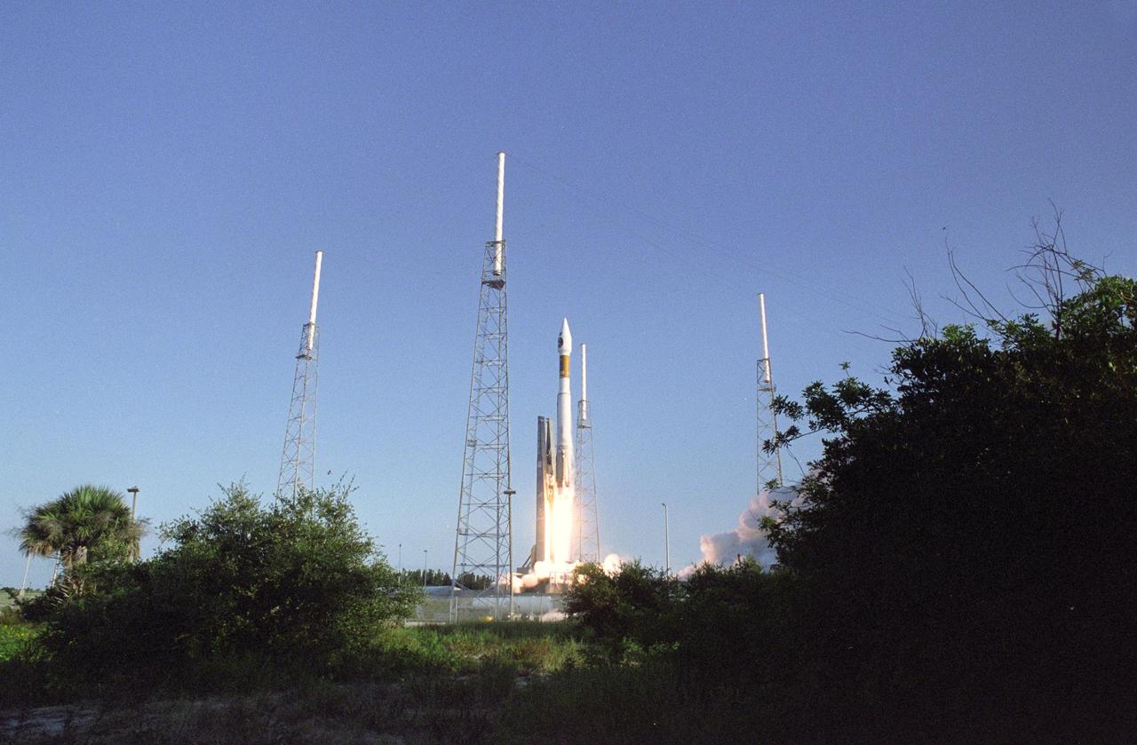
KENNEDY SPACE CENTER, FLA. - Viewed through a break in the greenscape around Launch Complex 41 at Cape Canaveral Air Force Station in Florida, the 19-stories-tall Atlas V launch vehicle roars off the launch pad, propelling the two-ton Mars Reconnaissance Orbiter (MRO) into a clear blue Florida sky and eventual orbit around Mars. Liftoff was at 7:43 a.m. EDT. All systems performed nominally for NASA's first launch of an Atlas V on an interplanetary mission. MRO established radio contact with controllers 61 minutes after launch and within four minutes of separation from the upper stage. Initial contact came through an antenna at the Japan Aerospace Exploration Agency's Uchinoura Space Center in southern Japan. Mars is 72 million miles from Earth today, but the spacecraft will travel more than four times that distance on its outbound-arc trajectory to intercept the red planet on March 10, 2006. The orbiter carries six scientific instruments for examining the surface, atmosphere and subsurface of Mars in unprecedented detail from low orbit. NASA expects to get several times more data about Mars from MRO than from all previous Martian missions combined. Researchers will use the instruments to learn more about the history and distribution of Mars' water. That information will improve understanding of planetary climate change and will help guide the quest to answer whether Mars ever supported life. The orbiter will also evaluate potential landing sites for future missions.
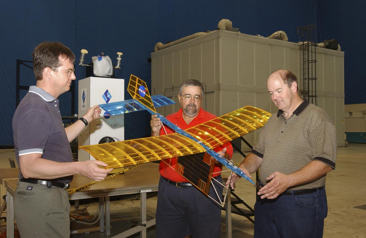
A team of NASA researchers from Marshall Space Flight Center (MSFC) and Dryden Flight Research center have proven that beamed light can be used to power an aircraft, a first-in-the-world accomplishment to the best of their knowledge. Using an experimental custom built radio-controlled model aircraft, the team has demonstrated a system that beams enough light energy from the ground to power the propeller of an aircraft and sustain it in flight. Special photovoltaic arrays on the plane, similar to solar cells, receive the light energy and convert it to electric current to drive the propeller motor. In a series of indoor flights this week at MSFC, a lightweight custom built laser beam was aimed at the airplane `s solar panels. The laser tracks the plane, maintaining power on its cells until the end of the flight when the laser is turned off and the airplane glides to a landing. The laser source demonstration represents the capability to beam more power to a plane so that it can reach higher altitudes and have a greater flight range without having to carry fuel or batteries, enabling an indefinite flight time. The demonstration was a collaborative effort between the Dryden Center at Edward's, California, where the aircraft was designed and built, and MSFC, where integration and testing of the laser and photovoltaic cells was done. Laser power beaming is a promising technology for consideration in new aircraft design and operation, and supports NASA's goals in the development of revolutionary aerospace technologies. Photographed with their invention are (from left to right): David Bushman and Tony Frackowiak, both of Dryden; and MSFC's Robert Burdine.
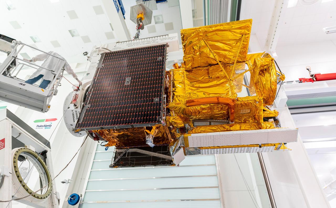
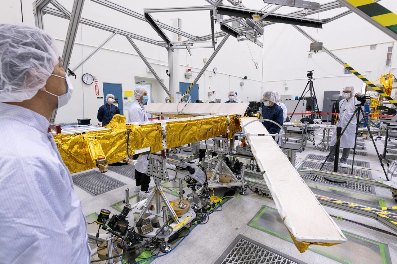
Workers in a clean room in Cannes, France, load the Surface Water and Ocean Topography (SWOT) satellite into a container in preparation for shipping the spacecraft to the U.S. SWOT is an international mission led by NASA and the French space agency Centre National d'Études Spatiales (CNES) that will survey water on more than 90% of Earth's surface. The spacecraft will view water in Earth's lakes, rivers, reservoirs, and the ocean in higher definition than ever before. The information that SWOT gathers will help inform water management decisions and prepare communities for rising seas and changing coastlines. It will also help researchers better understand the exchange of heat and carbon between the ocean and atmosphere, an important component of the role that Earth's ocean plays in the planet's climate. SWOT will launch out of the Vandenberg Space Force Base in central California no earlier than Dec. 5, 2022. SWOT is being jointly developed by NASA and CNES, with contributions from the Canadian Space Agency and the United Kingdom Space Agency. JPL, which is managed for NASA by Caltech in Pasadena, California, leads the U.S. component of the project. For the flight system payload, NASA is providing the KaRIn instrument, a GPS science receiver, a laser retroreflector, a two-beam microwave radiometer, and NASA instrument operations. CNES is providing the Doppler Orbitography and Radioposition Integrated by Satellite (DORIS) system, the dual frequency Poseidon altimeter (developed by Thales Alenia Space), the KaRIn radio-frequency subsystem (together with Thales Alenia Space and with support from the UK Space Agency), the platform, and ground control segment. CSA is providing the KaRIn high-power transmitter assembly. NASA is providing the launch vehicle and associated launch services. https://photojournal.jpl.nasa.gov/catalog/PIA24910
KENNEDY SPACE CENTER, FLA. - With the Atlantic Ocean as a backdrop, an Atlas V launch vehicle, 19 stories tall, with a two-ton Mars Reconnaissance Orbiter (MRO) on top, roars away from Launch Complex 41 at Cape Canaveral Air Force Station at 7:43 a.m. EDT. All systems performed nominally for NASA's first launch of an Atlas V on an interplanetary mission. MRO established radio contact with controllers 61 minutes after launch and within four minutes of separation from the upper stage. Initial contact came through an antenna at the Japan Aerospace Exploration Agency's Uchinoura Space Center in southern Japan. Mars is 72 million miles from Earth today, but the spacecraft will travel more than four times that distance on its outbound-arc trajectory to intercept the red planet on March 10, 2006. The orbiter carries six scientific instruments for examining the surface, atmosphere and subsurface of Mars in unprecedented detail from low orbit. NASA expects to get several times more data about Mars from MRO than from all previous Martian missions combined. Researchers will use the instruments to learn more about the history and distribution of Mars' water. That information will improve understanding of planetary climate change and will help guide the quest to answer whether Mars ever supported life. The orbiter will also evaluate potential landing sites for future missions. (Photo Credit: Pat Corkery/Lockheed Martin)
KENNEDY SPACE CENTER, FLA. - Trailing smoke and fire, an Atlas V launch vehicle, 19 stories tall, with a two-ton Mars Reconnaissance Orbiter (MRO) on top, roars away from Launch Complex 41 at Cape Canaveral Air Force Station at 7:43 a.m. EDT. All systems performed nominally for NASA's first launch of an Atlas V on an interplanetary mission. MRO established radio contact with controllers 61 minutes after launch and within four minutes of separation from the upper stage. Initial contact came through an antenna at the Japan Aerospace Exploration Agency's Uchinoura Space Center in southern Japan. Mars is 72 million miles from Earth today, but the spacecraft will travel more than four times that distance on its outbound-arc trajectory to intercept the red planet on March 10, 2006. The orbiter carries six scientific instruments for examining the surface, atmosphere and subsurface of Mars in unprecedented detail from low orbit. NASA expects to get several times more data about Mars from MRO than from all previous Martian missions combined. Researchers will use the instruments to learn more about the history and distribution of Mars' water. That information will improve understanding of planetary climate change and will help guide the quest to answer whether Mars ever supported life. The orbiter will also evaluate potential landing sites for future missions. (Photo Credit: Tom Rogers)
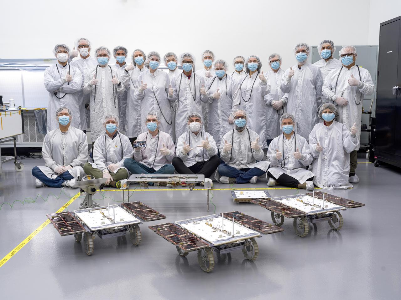
Members of the assembly, test, launch, and operations team for NASA's CADRE (Cooperative Autonomous Distributed Robotic Exploration) project pose in a clean room at the agency's Jet Propulsion Laboratory in Southern California on Jan. 26, 2024, with three lunar rovers after their completion. Bound for the Moon, CADRE is a technology demonstration designed to show that a group of robotic spacecraft can work together as a team to accomplish tasks and record data autonomously – without explicit commands from mission controllers on Earth. Seen behind the rovers are hardware elements that will be mounted on the lunar lander aboard which CADRE will arrive at the Moon: the situational awareness camera assembly (SACA), one of the deployers that will lower the rovers onto the lunar surface, and the base station with which the rovers will communicate via mesh network radios. Back row, from left: Wei Chen Wilson Yeh, Mark White, Nathan Cheek, Baylor de los Reyes, Jacqueline Sly, Blair Emanuel, Josh Miller, Jonathan Tan, Sawyer Brooks, Libby Boroson, Leroy Montalvo, Tonya Beatty, Bert Turney, George Dupas, Leo Ortiz, and Nelson Serrano. Front row, from left: Kristopher Sherril, Coleman Richdale, Russell Smith, Daniel Esguerra, Will Raff, Justin Schachter, and Clara Nguyen. Shown on the cellphone held by Smith are absent ATLO team members Ara Kourchians, Molly Shelton, and Randy Ballat. https://photojournal.jpl.nasa.gov/catalog/PIA26165
KENNEDY SPACE CENTER, FLA. - With the Atlantic Ocean as a backdrop, an Atlas V launch vehicle, 19 stories tall, with a two-ton Mars Reconnaissance Orbiter (MRO) on top, roars away from Launch Complex 41 at Cape Canaveral Air Force Station at 7:43 a.m. EDT. All systems performed nominally for NASA's first launch of an Atlas V on an interplanetary mission. MRO established radio contact with controllers 61 minutes after launch and within four minutes of separation from the upper stage. Initial contact came through an antenna at the Japan Aerospace Exploration Agency's Uchinoura Space Center in southern Japan. Mars is 72 million miles from Earth today, but the spacecraft will travel more than four times that distance on its outbound-arc trajectory to intercept the red planet on March 10, 2006. The orbiter carries six scientific instruments for examining the surface, atmosphere and subsurface of Mars in unprecedented detail from low orbit. NASA expects to get several times more data about Mars from MRO than from all previous Martian missions combined. Researchers will use the instruments to learn more about the history and distribution of Mars' water. That information will improve understanding of planetary climate change and will help guide the quest to answer whether Mars ever supported life. The orbiter will also evaluate potential landing sites for future missions. (Photo Credit: Pat Corkery/Lockheed Martin)

NASA's Hubble Space Telescope has helped astronomers find the final piece of a celestial puzzle by nabbing a third runaway star. As British royal families fought the War of the Roses in the 1400s for control of England's throne, a grouping of stars was waging its own contentious skirmish — a star war far away in the Orion Nebula. The stars were battling each other in a gravitational tussle, which ended with the system breaking apart and at least three stars being ejected in different directions. The speedy, wayward stars went unnoticed for hundreds of years until, over the past few decades, two of them were spotted in infrared and radio observations, which could penetrate the thick dust in the Orion Nebula. Read more: <a href="https://go.nasa.gov/2ni3EZX" rel="nofollow">go.nasa.gov/2ni3EZX</a> <b><a href="http://www.nasa.gov/audience/formedia/features/MP_Photo_Guidelines.html" rel="nofollow">NASA image use policy.</a></b> <b><a href="http://www.nasa.gov/centers/goddard/home/index.html" rel="nofollow">NASA Goddard Space Flight Center</a></b> enables NASA’s mission through four scientific endeavors: Earth Science, Heliophysics, Solar System Exploration, and Astrophysics. Goddard plays a leading role in NASA’s accomplishments by contributing compelling scientific knowledge to advance the Agency’s mission. <b>Follow us on <a href="http://twitter.com/NASAGoddardPix" rel="nofollow">Twitter</a></b> <b>Like us on <a href="http://www.facebook.com/pages/Greenbelt-MD/NASA-Goddard/395013845897?ref=tsd" rel="nofollow">Facebook</a></b> <b>Find us on <a href="http://instagrid.me/nasagoddard/?vm=grid" rel="nofollow">Instagram</a></b>
KENNEDY SPACE CENTER, FLA. - Trailing smoke and fire, the 19-stories-tall Atlas V launch vehicle, with a two-ton Mars Reconnaissance Orbiter (MRO) on top, roars away from Launch Complex 41 at Cape Canaveral Air Force Station at 7:43 a.m. EDT. All systems performed nominally for NASA's first launch of an Atlas V on an interplanetary mission. MRO established radio contact with controllers 61 minutes after launch and within four minutes of separation from the upper stage. Initial contact came through an antenna at the Japan Aerospace Exploration Agency's Uchinoura Space Center in southern Japan. Mars is 72 million miles from Earth today, but the spacecraft will travel more than four times that distance on its outbound-arc trajectory to intercept the red planet on March 10, 2006. The orbiter carries six scientific instruments for examining the surface, atmosphere and subsurface of Mars in unprecedented detail from low orbit. NASA expects to get several times more data about Mars from MRO than from all previous Martian missions combined. Researchers will use the instruments to learn more about the history and distribution of Mars' water. That information will improve understanding of planetary climate change and will help guide the quest to answer whether Mars ever supported life. The orbiter will also evaluate potential landing sites for future missions. (Photo Credit: Tom Rogers)
KENNEDY SPACE CENTER, FLA. - Just minutes after liftoff, the 19-stories-tall Atlas V launch vehicle, with a two-ton Mars Reconnaissance Orbiter (MRO) on top, roars into the clear blue sky from Launch Complex 41 at Cape Canaveral Air Force Station. Liftoff was at 7:43 a.m. EDT. All systems performed nominally for NASA's first launch of an Atlas V on an interplanetary mission. MRO established radio contact with controllers 61 minutes after launch and within four minutes of separation from the upper stage. Initial contact came through an antenna at the Japan Aerospace Exploration Agency's Uchinoura Space Center in southern Japan. Mars is 72 million miles from Earth today, but the spacecraft will travel more than four times that distance on its outbound-arc trajectory to intercept the red planet on March 10, 2006. The orbiter carries six scientific instruments for examining the surface, atmosphere and subsurface of Mars in unprecedented detail from low orbit. NASA expects to get several times more data about Mars from MRO than from all previous Martian missions combined. Researchers will use the instruments to learn more about the history and distribution of Mars' water. That information will improve understanding of planetary climate change and will help guide the quest to answer whether Mars ever supported life. The orbiter will also evaluate potential landing sites for future missions. (Photo Credit: Tom Rogers)
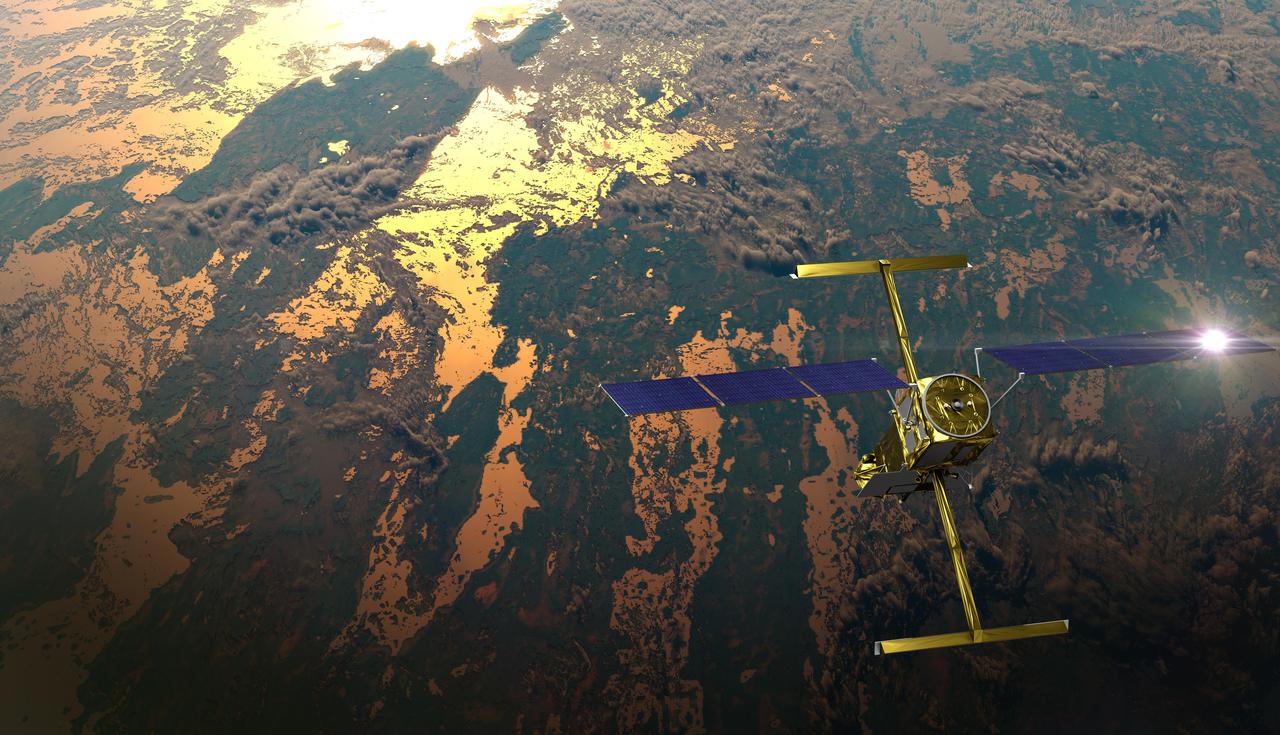
The international Surface Water and Ocean Topography (SWOT) satellite is shown in orbit over Earth in this illustration, with sunlight glinting off one of its solar arrays and both antennas of its Ka-band Radar Interferometer (KaRIn) instrument extended. The mission is a collaborative effort between NASA and the French space agency Centre National d'Études Spatiales (CNES) – with contributions from the Canadian Space Agency (CSA) and the UK Space Agency. KaRIn is the scientific heart of the SWOT satellite, which will survey the water on more than 90% of Earth's surface, measuring the height of water in lakes, rivers, reservoirs, and the ocean. To do that, KaRIn will transmit radar pulses to Earth's surface and use its two antennas to triangulate the return signals that bounce back. Mounted at the ends of a boom 33 feet (10 meters) long, the antennas will collect data along a swath 30 miles (50 kilometers) wide on either side of the satellite. KaRIn will operate in two modes: A lower-resolution mode over the ocean will involve significant onboard processing of the data to reduce the volume of information sent during downlinks to Earth; a higher-resolution mode will be used mainly over land. Scheduled to launch from Vandenberg Space Force Base in Central California on Dec. 15, 2022, SWOT is being jointly developed by NASA and CNES, with contributions from the CSA and the UK Space Agency. NASA's Jet Propulsion Laboratory, which is managed for the agency by Caltech in Pasadena, California, leads the U.S. component of the project. For the flight system payload, NASA is providing the Ka-band Radar Interferometer (KaRIn) instrument, a GPS science receiver, a laser retroreflector, a two-beam microwave radiometer, and NASA instrument operations. CNES is providing the Doppler Orbitography and Radioposition Integrated by Satellite (DORIS) system, the dual frequency Poseidon altimeter (developed by Thales Alenia Space), the KaRIn radio-frequency subsystem (together with Thales Alenia Space and with support from the UK Space Agency), the satellite platform, and ground control segment. CSA is providing the KaRIn high-power transmitter assembly. NASA is providing the launch vehicle and associated launch services. https://photojournal.jpl.nasa.gov/catalog/PIA25595
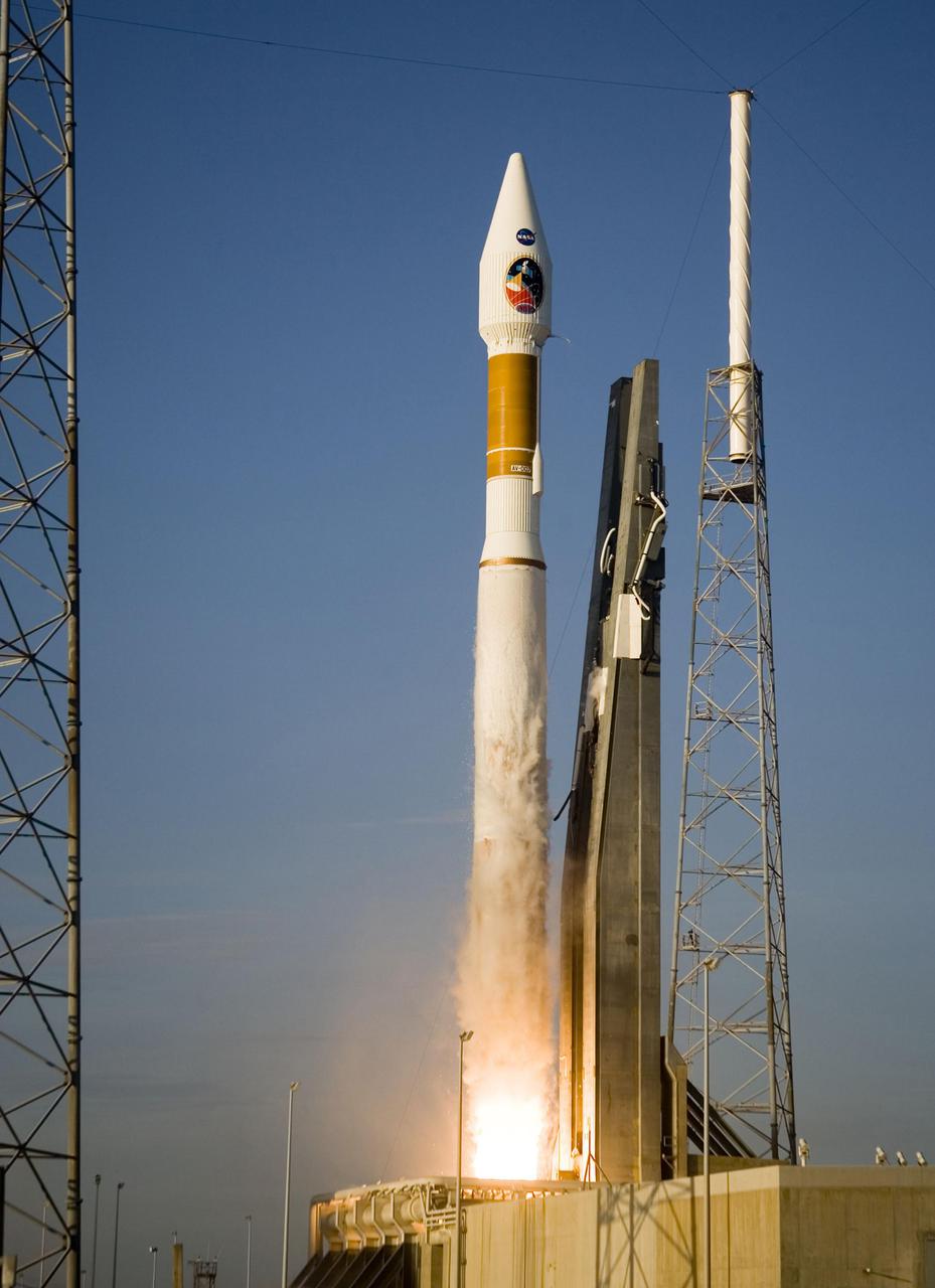
KENNEDY SPACE CENTER, FLA. - At 7:43 a.m. EDT an Atlas V launch vehicle, 19 stories tall, with a two-ton Mars Reconnaissance Orbiter (MRO) on top, lifts off the pad on Launch Complex 41 at Cape Canaveral Air Force Station in Florida. All systems performed nominally for NASA's first launch of an Atlas V on an interplanetary mission. MRO established radio contact with controllers 61 minutes after launch and within four minutes of separation from the upper stage. Initial contact came through an antenna at the Japan Aerospace Exploration Agency's Uchinoura Space Center in southern Japan. Mars is 72 million miles from Earth today, but the spacecraft will travel more than four times that distance on its outbound-arc trajectory to intercept the red planet on March 10, 2006. The orbiter carries six scientific instruments for examining the surface, atmosphere and subsurface of Mars in unprecedented detail from low orbit. NASA expects to get several times more data about Mars from MRO than from all previous Martian missions combined. Researchers will use the instruments to learn more about the history and distribution of Mars' water. That information will improve understanding of planetary climate change and will help guide the quest to answer whether Mars ever supported life. The orbiter will also evaluate potential landing sites for future missions. (Photo Credit: Tom Rogers)
Members of the international Surface Water and Ocean Topography (SWOT) mission test one of the antennas for the Ka-band Radar Interferometer (KaRIn) instrument in a clean room at NASA's Jet Propulsion Laboratory in Southern California. The mission is a collaborative effort between NASA and the French space agency Centre National d'Études Spatiales (CNES) – with contributions from the Canadian Space Agency (CSA) and the UK Space Agency. KaRIn is the scientific heart of the SWOT satellite, which will survey the water on more than 90% of Earth's surface, measuring the height of water in lakes, rivers, reservoirs, and the ocean. To do that, KaRIn will transmit radar pulses to Earth's surface and use its two antennas to triangulate the return signals that bounce back. Mounted at the ends of a boom 33 feet (10 meters) long, the antennas will collect data along a swath 30 miles (50 kilometers) wide on either side of the satellite. KaRIn will operate in two modes: A lower-resolution mode over the ocean will involve significant onboard processing of the data to reduce the volume of information sent during downlinks to Earth; a higher-resolution mode will be used mainly over land. Scheduled to launch from Vandenberg Space Force Base in Central California on Dec. 15, 2022, SWOT is being jointly developed by NASA and CNES, with contributions from the CSA and the UK Space Agency. NASA's Jet Propulsion Laboratory, which is managed for the agency by Caltech in Pasadena, California, leads the U.S. component of the project. For the flight system payload, NASA is providing the Ka-band Radar Interferometer (KaRIn) instrument, a GPS science receiver, a laser retroreflector, a two-beam microwave radiometer, and NASA instrument operations. CNES is providing the Doppler Orbitography and Radioposition Integrated by Satellite (DORIS) system, the dual frequency Poseidon altimeter (developed by Thales Alenia Space), the KaRIn radio-frequency subsystem (together with Thales Alenia Space and with support from the UK Space Agency), the satellite platform, and ground control segment. CSA is providing the KaRIn high-power transmitter assembly. NASA is providing the launch vehicle and associated launch services. https://photojournal.jpl.nasa.gov/catalog/PIA25594
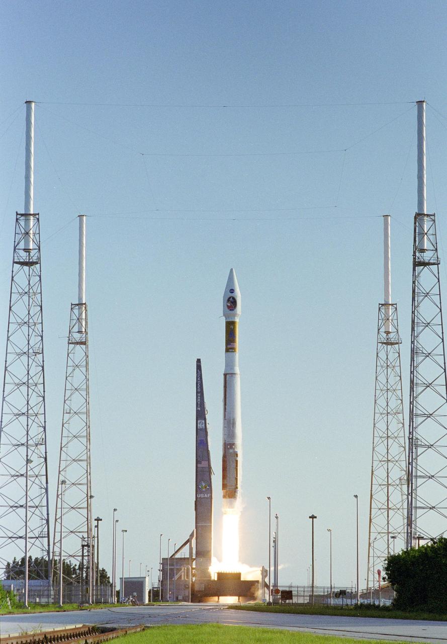
KENNEDY SPACE CENTER, FLA. - The 19-stories-tall Atlas V launch vehicle, with a two-ton Mars Reconnaissance Orbiter (MRO) on top, leaps away from Launch Complex 41 at Cape Canaveral Air Force Station at 7:43 a.m. EDT. All systems performed nominally for NASA's first launch of an Atlas V on an interplanetary mission. MRO established radio contact with controllers 61 minutes after launch and within four minutes of separation from the upper stage. Initial contact came through an antenna at the Japan Aerospace Exploration Agency's Uchinoura Space Center in southern Japan. Mars is 72 million miles from Earth today, but the spacecraft will travel more than four times that distance on its outbound-arc trajectory to intercept the red planet on March 10, 2006. The orbiter carries six scientific instruments for examining the surface, atmosphere and subsurface of Mars in unprecedented detail from low orbit. NASA expects to get several times more data about Mars from MRO than from all previous Martian missions combined. Researchers will use the instruments to learn more about the history and distribution of Mars' water. That information will improve understanding of planetary climate change and will help guide the quest to answer whether Mars ever supported life. The orbiter will also evaluate potential landing sites for future missions.
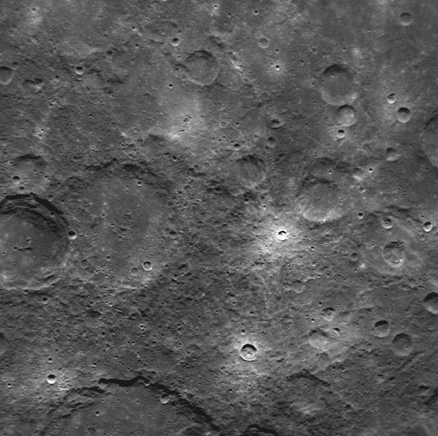
NASA image acquired: March 29, 2011 This is the first image of Mercury taken from orbit with MESSENGER’s Narrow Angle Camera (NAC). MESSENGER’s camera system, the Mercury Dual Imaging System (MDIS), has two cameras: the Narrow Angle Camera and the Wide Angle Camera (WAC). Comparison of this image with MESSENGER’s first WAC image of the same region shows the substantial difference between the fields of view of the two cameras. At 1.5°, the field of view of the NAC is seven times smaller than the 10.5° field of view of the WAC. This image was taken using MDIS’s pivot. MDIS is mounted on a pivoting platform and is the only instrument in MESSENGER’s payload capable of movement independent of the spacecraft. The other instruments are fixed in place, and most point down the spacecraft’s boresight at all times, relying solely on the guidance and control system for pointing. The 90° range of motion of the pivot gives MDIS a much-needed extra degree of freedom, allowing MDIS to image the planet’s surface at times when spacecraft geometry would normally prevent it from doing so. The pivot also gives MDIS additional imaging opportunities by allowing it to view more of the surface than that at which the boresight-aligned instruments are pointed at any given time. On March 17, 2011 (March 18, 2011, UTC), MESSENGER became the first spacecraft ever to orbit the planet Mercury. The mission is currently in the commissioning phase, during which spacecraft and instrument performance are verified through a series of specially designed checkout activities. In the course of the one-year primary mission, the spacecraft's seven scientific instruments and radio science investigation will unravel the history and evolution of the Solar System's innermost planet. Visit the Why Mercury? section of this website to learn more about the science questions that the MESSENGER mission has set out to answer. Credit: NASA/Johns Hopkins University Applied Physics Laboratory/Carnegie Institution of Washington <b><a href="http://www.nasa.gov/centers/goddard/home/index.html" rel="nofollow">NASA Goddard Space Flight Center</a></b> enables NASA’s mission through four scientific endeavors: Earth Science, Heliophysics, Solar System Exploration, and Astrophysics. Goddard plays a leading role in NASA’s accomplishments by contributing compelling scientific knowledge to advance the Agency’s mission. <b>Follow us on <a href="http://twitter.com/NASA_GoddardPix" rel="nofollow">Twitter</a></b> <b>Join us on <a href="http://www.facebook.com/pages/Greenbelt-MD/NASA-Goddard/395013845897?ref=tsd" rel="nofollow">Facebook</a></b>
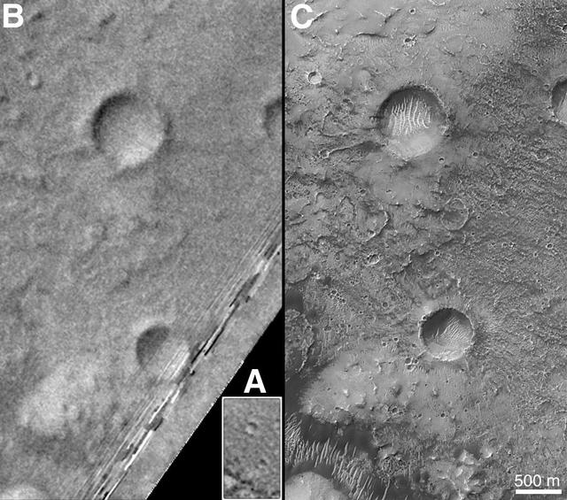
On Earth, the longitude of the Royal Observatory in Greenwich, England is defined as the "prime meridian," or the zero point of longitude. Locations on Earth are measured in degrees east or west from this position. The prime meridian was defined by international agreement in 1884 as the position of the large "transit circle," a telescope in the Observatory's Meridian Building. The transit circle was built by Sir George Biddell Airy, the 7th Astronomer Royal, in 1850. (While visual observations with transits were the basis of navigation until the space age, it is interesting to note that the current definition of the prime meridian is in reference to orbiting satellites and Very Long Baseline Interferometry (VLBI) measurements of distant radio sources such as quasars. This "International Reference Meridian" is now about 100 meters east of the Airy Transit at Greenwich.) For Mars, the prime meridian was first defined by the German astronomers W. Beer and J. H. Mädler in 1830-32. They used a small circular feature, which they designated "a," as a reference point to determine the rotation period of the planet. The Italian astronomer G. V. Schiaparelli, in his 1877 map of Mars, used this feature as the zero point of longitude. It was subsequently named Sinus Meridiani ("Middle Bay") by Camille Flammarion. When Mariner 9 mapped the planet at about 1 kilometer (0.62 mile) resolution in 1972, an extensive "control net" of locations was computed by Merton Davies of the RAND Corporation. Davies designated a 0.5-kilometer-wide crater (0.3 miles wide), subsequently named "Airy-0" (within the large crater Airy in Sinus Meridiani) as the longitude zero point. (Airy, of course, was named to commemorate the builder of the Greenwich transit.) This crater was imaged once by Mariner 9 (the 3rd picture taken on its 533rd orbit, 533B03) and once by the Viking 1 orbiter in 1978 (the 46th image on that spacecraft's 746th orbit, 746A46), and these two images were the basis of the martian longitude system for the rest of the 20th Century. The Mars Global Surveyor (MGS) Mars Orbiter Camera (MOC) has attempted to take a picture of Airy-0 on every close overflight since the beginning of the MGS mapping mission. It is a measure of the difficulty of hitting such a small target that nine attempts were required, since the spacecraft did not pass directly over Airy-0 until almost the end of the MGS primary mission, on orbit 8280 (January 13, 2001). In the left figure above, the outlines of the Mariner 9, Viking, and Mars Global Surveyor images are shown on a MOC wide angle context image, M23-00924. In the right figure, sections of each of the three images showing the crater Airy-0 are presented. A is a piece of the Mariner 9 image, B is from the Viking image, and C is from the MGS image. Airy-0 is the larger crater toward the top-center in each frame. The MOC observations of Airy-0 not only provide a detailed geological close-up of this historic reference feature, they will be used to improve our knowledge of the locations of all features on Mars, which will in turn enable more precise landings on the Red Planet by future spacecraft and explorers. http://photojournal.jpl.nasa.gov/catalog/PIA03207

As we head into the 21st Century, it seems hard to believe that human beings have been sending spacecraft toward Mars for more than 3 decades already. The first spacecraft to reach Mars was Mariner 4 in 1965. This success was followed by two spacecraft in 1969, Mariners 6 and 7. Now the wonders and alien beauty of Mars continue to unfold with each day that the Mars Global Surveyor -- which arrived in September 1997 -- continues to radio its data to Earth. Mars exploration was always difficult and each bit of data returned from the planet is a marvel. On August 5, 1969, the Mariner 7 spacecraft flew past Mars at a minimum altitude of about 4200 km. It acquired 14 wide/narrow angle image pairs during the few minutes of the "near encounter" flyby. One of these image pairs, 7N19/7N20, shows the south polar region and contains a feature that at the time was nicknamed "the Giant's Footprint." Shown in the first two pictures, above, the feature consists of two adjoining craters, one about 80 km (50 mi) in diameter and the other about 50 km (31 mi) across near latitude 76°S, longitude 276°W. The oblique geometry of the Mariner 7 image enhances the impression of a footprint. The "Giant's Footprint" was almost missed when Mariner 7 suffered a near-catastrophic battery failure just a few days before the encounter -- on July 30 -- that put the spacecraft sporadically out of contact with Earth for two days. Ground controllers at the Jet Propulsion Laboratory (JPL)recovered the spacecraft, re-planned its imaging sequence based on results from the Mariner 6 flyby on July 31, and salvaged all of the mission's science goals in under a week! In the 1970's, the larger crater in "giant's footprint" was named "Vishniac" in honor of Wolf Vishniac, an American microbiologist of the University of Rochester who was instrumental in the development of methods to search for life on Mars. Vishniac was tragically killed in a fall in Antarctica in 1973 while retrieving a life detection experiment, and the crater was named in honor of this "giant" in the search for life on Mars. More than three decades after the Mariner 7 flyby, Mars Global Surveyor's Mars Orbiter Camera (MOC) acquired a commemorative view of the interior of Vishniac Crater on October 25, 1999. The context image and the 3-meters (9.8 feet)-per-pixel narrow angle view are shown above (in the lower image pair). Mariner 7's 7N20 has a nominal resolution of about 180 meters (591 feet) per pixel, while the MOC high resolution view is about 60 times higher (in actuality, the lower quality of the Mariner 7 images makes the resolution gain even more dramatic). The MOC high resolution view (lower right, above) shows a 1.5 kilometer-(0.9 mile)-wide portion of the floor of Vishniac in the process of defrosting during southern spring. The bright areas are still frost-covered, while the darker areas are either defrosted or composed of darkened or "dirty" frost. The dark patches in the image seem to serve as sources for dark streaks of material that has either been blown across the landscape by wind, or has somehow caused the erosion of frost to create the streaks. Dark streaks follow the local topography, as might the wind that blew across this landscape. This pattern of spots and streaks was quite common on the defrosting south polar cap during the spring that lasted from early August 1999 to late December 1999. All images shown here are illuminated by sunlight from the lower right. Image orientation with north toward the bottom was selected in order to show the "footprint" visible in Mariner 7 image 7N20. The Mariner 7 images were recovered at Malin Space Science Systems from the original 7-track magnetic tapes, archived on CD-ROM by the JPL Data Preservation activity. More images relating to the release can be viewed at http://photojournal.jpl.nasa.gov/catalog/PIA02365