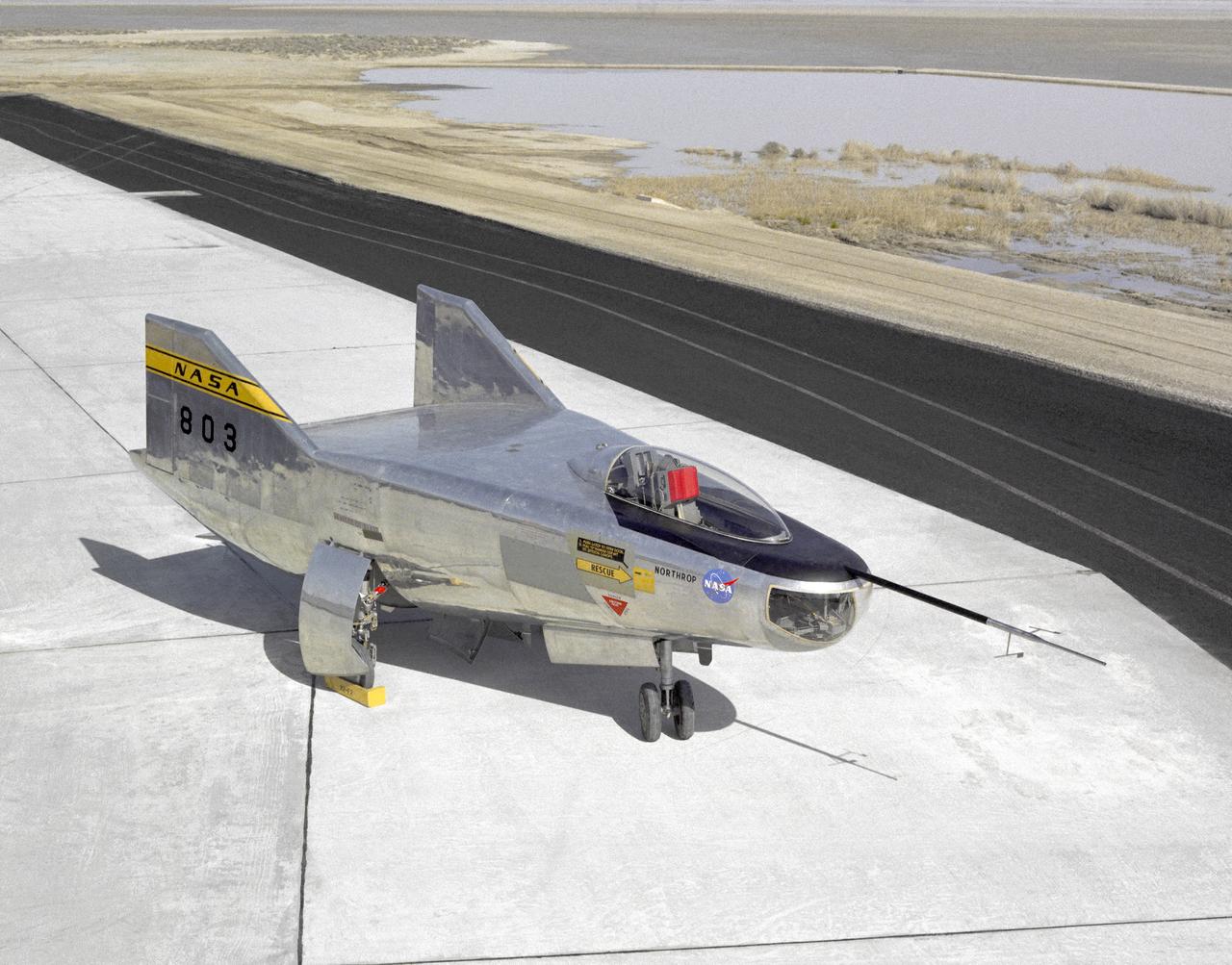
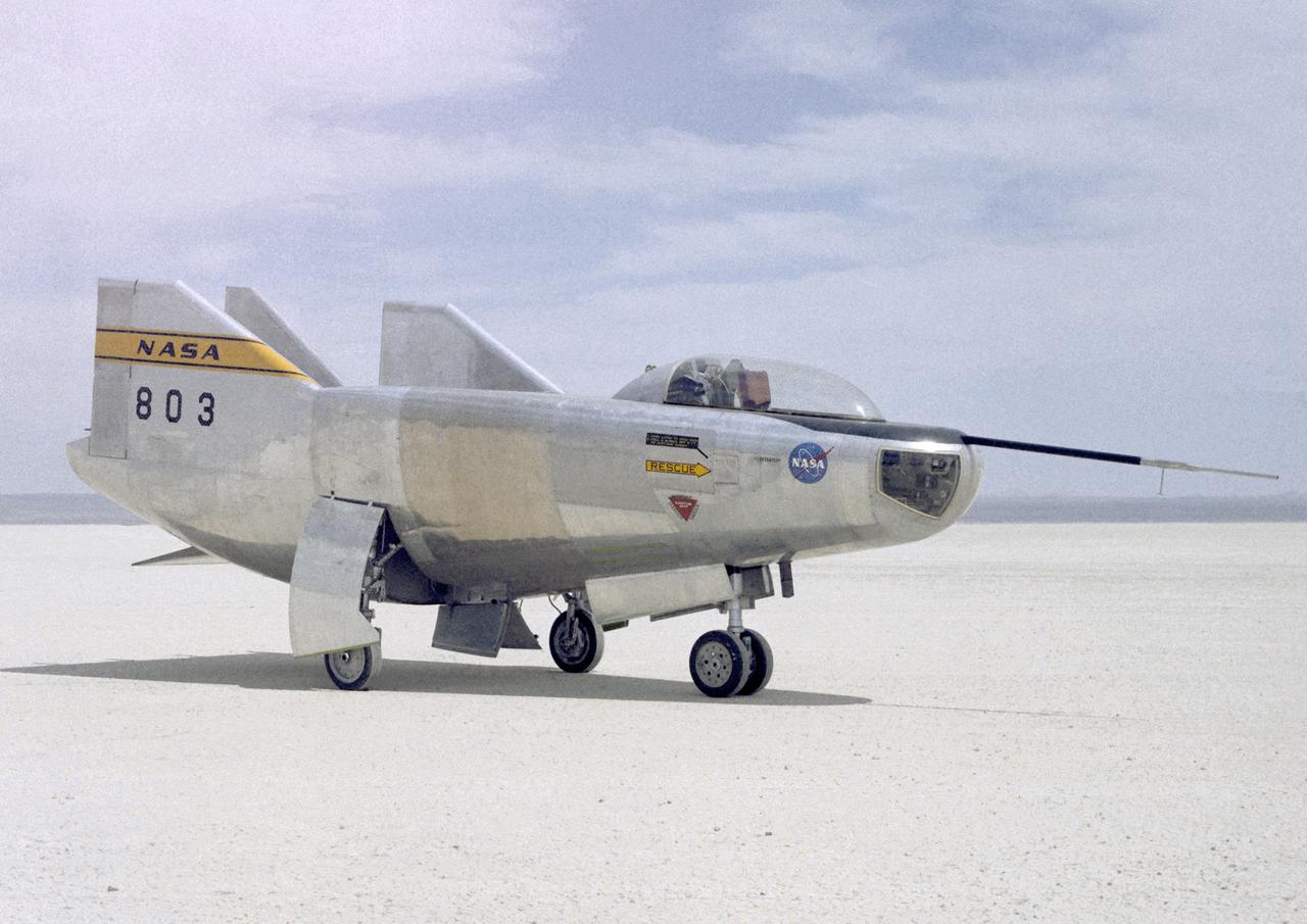
The M2-F2 Lifting Body is seen here on the ramp at the NASA Dryden Flight Research Center. The success of Dryden's M2-F1 program led to NASA's development and construction of two heavyweight lifting bodies based on studies at NASA's Ames and Langley research centers -- the M2-F2 and the HL-10, both built by the Northrop Corporation. The "M" refers to "manned" and "F" refers to "flight" version. "HL" comes from "horizontal landing" and 10 is for the tenth lifting body model to be investigated by Langley. The first flight of the M2-F2 -- which looked much like the "F1" -- was on July 12, 1966. Milt Thompson was the pilot. By then, the same B-52 used to air launch the famed X-15 rocket research aircraft was modified to also carry the lifting bodies. Thompson was dropped from the B-52's wing pylon mount at an altitude of 45,000 feet on that maiden glide flight. The M2-F2 weighed 4,620 pounds, was 22 feet long, and had a width of about 10 feet. On May 10, 1967, during the sixteenth glide flight leading up to powered flight, a landing accident severely damaged the vehicle and seriously injured the NASA pilot, Bruce Peterson. NASA pilots and researchers realized the M2-F2 had lateral control problems, even though it had a stability augmentation control system. When the M2-F2 was rebuilt at Dryden and redesignated the M2-F3, it was modified with an additional third vertical fin -- centered between the tip fins -- to improve control characteristics. The M2-F2/F3 was the first of the heavy-weight, entry-configuration lifting bodies. Its successful development as a research test vehicle answered many of the generic questions about these vehicles. NASA donated the M2-F3 vehicle to the Smithsonian Institute in December 1973. It is currently hanging in the Air and Space Museum along with the X-15 aircraft number 1, which was its hangar partner at Dryden from 1965 to 1969.
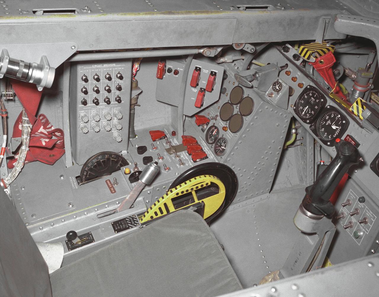
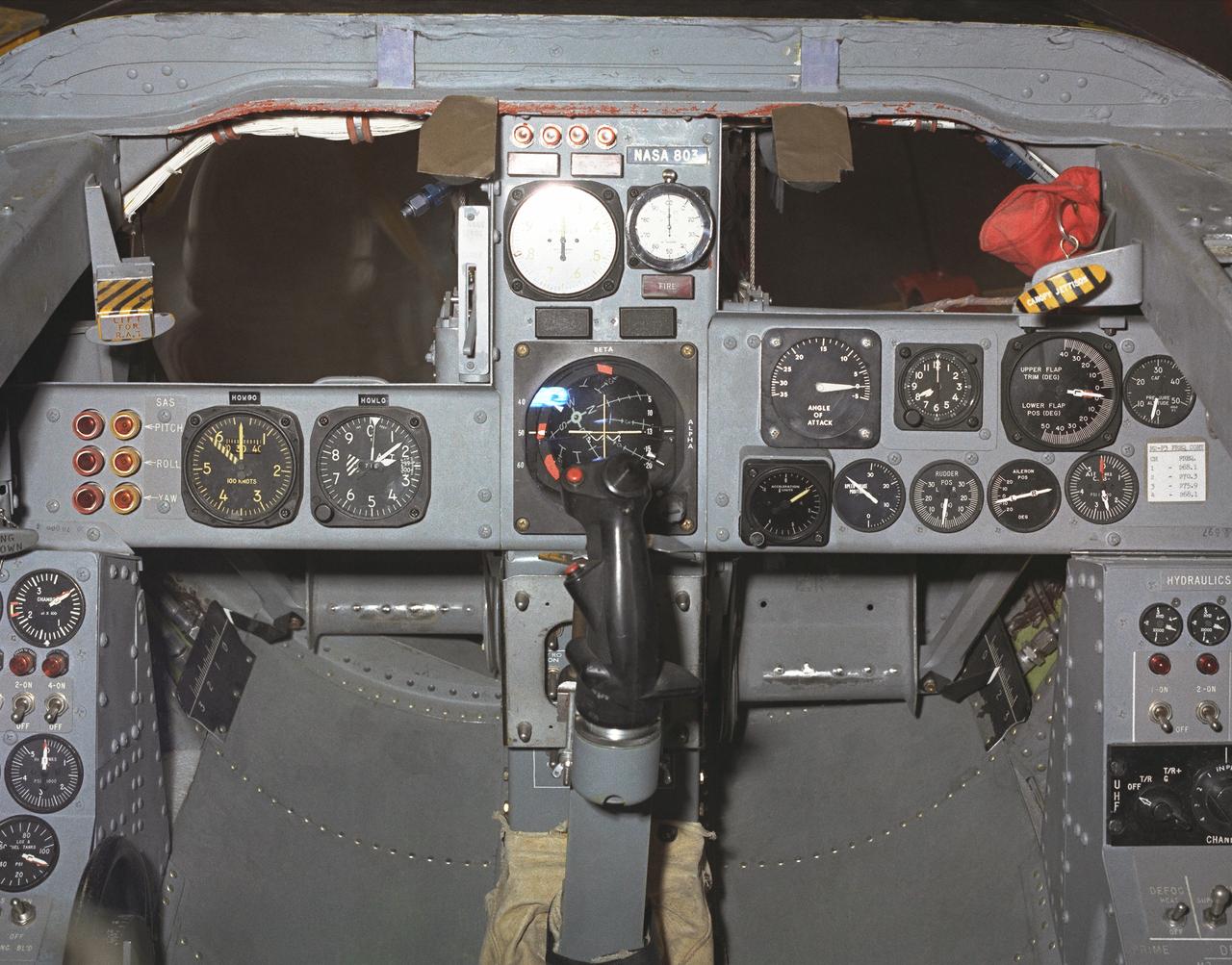
This photo shows the left side cockpit instrumentation panel of the M2-F2 Lifting Body. The success of Dryden's M2-F1 program led to NASA's development and construction of two heavyweight lifting bodies based on studies at NASA's Ames and Langley research centers -- the M2-F2 and the HL-10, both built by the Northrop Corporation. The "M" refers to "manned" and "F" refers to "flight" version. "HL" comes from "horizontal landing" and 10 is for the tenth lifting body model to be investigated by Langley. The first flight of the M2-F2 -- which looked much like the "F1" -- was on July 12, 1966. Milt Thompson was the pilot. By then, the same B-52 used to air launch the famed X-15 rocket research aircraft was modified to also carry the lifting bodies. Thompson was dropped from the B-52's wing pylon mount at an altitude of 45,000 feet on that maiden glide flight. The M2-F2 weighed 4,620 pounds, was 22 feet long, and had a width of about 10 feet. On May 10, 1967, during the sixteenth glide flight leading up to powered flight, a landing accident severely damaged the vehicle and seriously injured the NASA pilot, Bruce Peterson. NASA pilots and researchers realized the M2-F2 had lateral control problems, even though it had a stability augmentation control system. When the M2-F2 was rebuilt at Dryden and redesignated the M2-F3, it was modified with an additional third vertical fin -- centered between the tip fins -- to improve control characteristics. The M2-F2/F3 was the first of the heavy-weight, entry-configuration lifting bodies. Its successful development as a research test vehicle answered many of the generic questions about these vehicles. NASA donated the M2-F3 vehicle to the Smithsonian Institute in December 1973. It is currently hanging in the Air and Space Museum along with the X-15 aircraft number 1, which was its hangar partner at Dryden from 1965 to 1969.
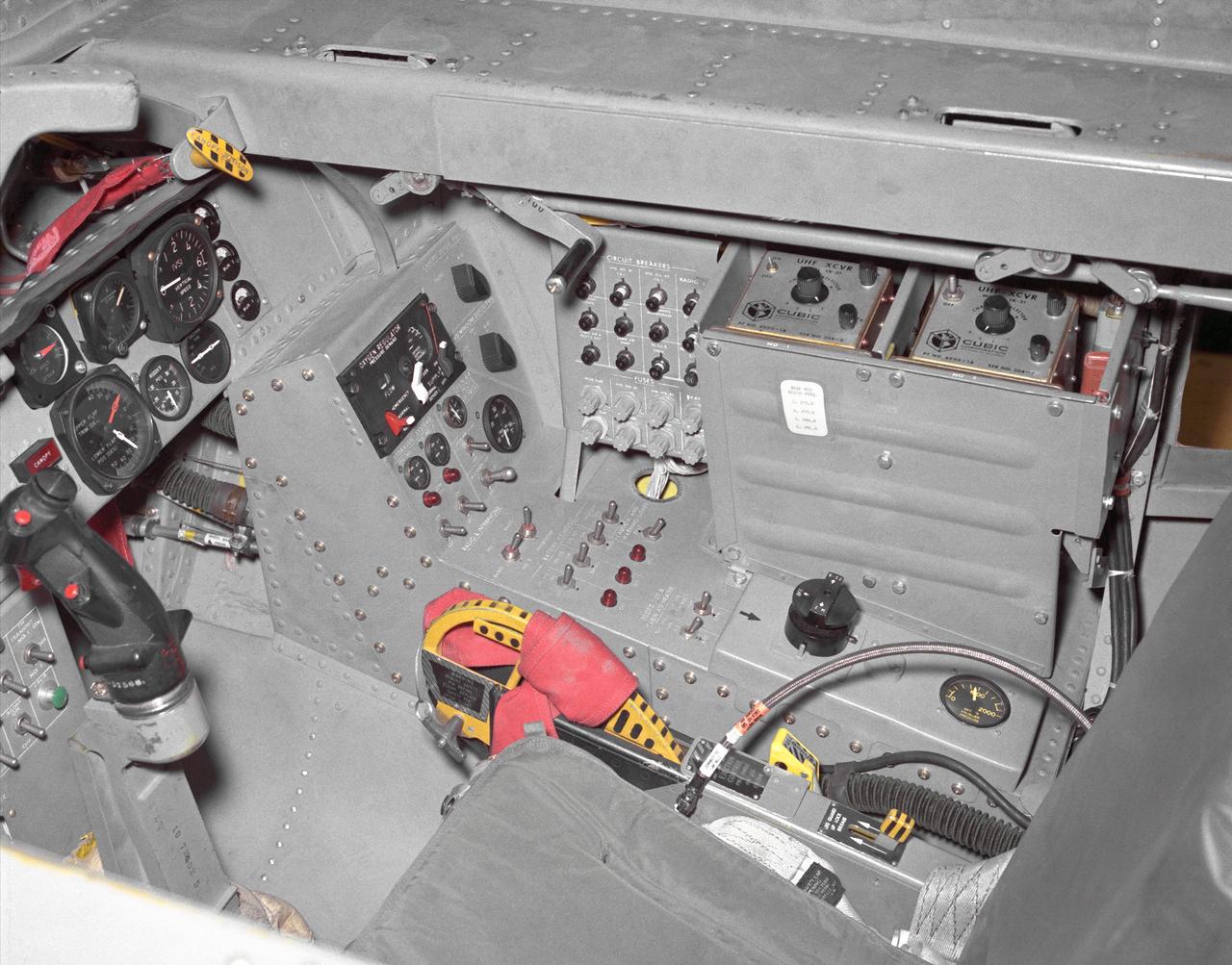
This photo shows the right side cockpit instrumentation panel of the M2-F2 Lifting Body. The success of Dryden's M2-F1 program led to NASA's development and construction of two heavyweight lifting bodies based on studies at NASA's Ames and Langley research centers -- the M2-F2 and the HL-10, both built by the Northrop Corporation. The "M" refers to "manned" and "F" refers to "flight" version. "HL" comes from "horizontal landing" and 10 is for the tenth lifting body model to be investigated by Langley. The first flight of the M2-F2 -- which looked much like the "F1" -- was on July 12, 1966. Milt Thompson was the pilot. By then, the same B-52 used to air launch the famed X-15 rocket research aircraft was modified to also carry the lifting bodies. Thompson was dropped from the B-52's wing pylon mount at an altitude of 45,000 feet on that maiden glide flight. The M2-F2 weighed 4,620 pounds, was 22 feet long, and had a width of about 10 feet. On May 10, 1967, during the sixteenth glide flight leading up to powered flight, a landing accident severely damaged the vehicle and seriously injured the NASA pilot, Bruce Peterson. NASA pilots and researchers realized the M2-F2 had lateral control problems, even though it had a stability augmentation control system. When the M2-F2 was rebuilt at Dryden and redesignated the M2-F3, it was modified with an additional third vertical fin -- centered between the tip fins -- to improve control characteristics. The M2-F2/F3 was the first of the heavy-weight, entry-configuration lifting bodies. Its successful development as a research test vehicle answered many of the generic questions about these vehicles. NASA donated the M2-F3 vehicle to the Smithsonian Institute in December 1973. It is currently hanging in the Air and Space Museum along with the X-15 aircraft number 1, which was its hangar partner at Dryden from 1965 to 1969.
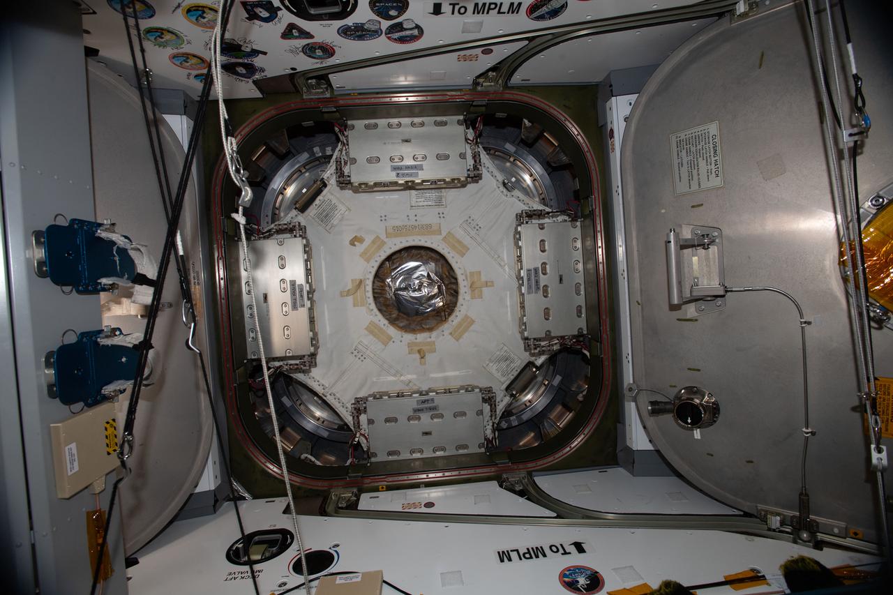
iss057e059085 (11/7/2018) --- Photo documentation of the Common Berthing Mechanism (CBM) Center Disk Cover in the Harmony Node 2 nadir hatch during part 2 of Kounotori H-II Transfer Vehicle 7 (HTV-7) Vestibule configuration for demating. The HTV Small Re-entry Capsule (HSRC) Protective Cover has been removed.

iss057e059103 (11/7/2018) --- Photo documentation of the area behind the Common Berthing Mechanism (CBM) Center Disk Cover in the Harmony Node 2 nadir hatch during part 2 of Kounotori H-II Transfer Vehicle 7 (HTV-7) Vestibule configuration for demating. The HTV Small Re-entry Capsule (HSRC) Protective Cover has been removed.
The M2-F3 Lifting Body is seen here on the lakebed next to the NASA Flight Research Center (FRC--later Dryden Flight Research Center), Edwards, California. The May 1967 crash of the M2-F2 had torn off the left fin and landing gear. It had also damaged the external skin and internal structure. Flight Research Center engineers worked with Ames Research Center and the Air Force in redesigning the vehicle with a center fin to provide greater stability. Then Northrop Corporation cooperated with the FRC in rebuilding the vehicle. The entire process took three years.
This photo shows the cockpit instrument panel of the M2-F3 Lifting Body.
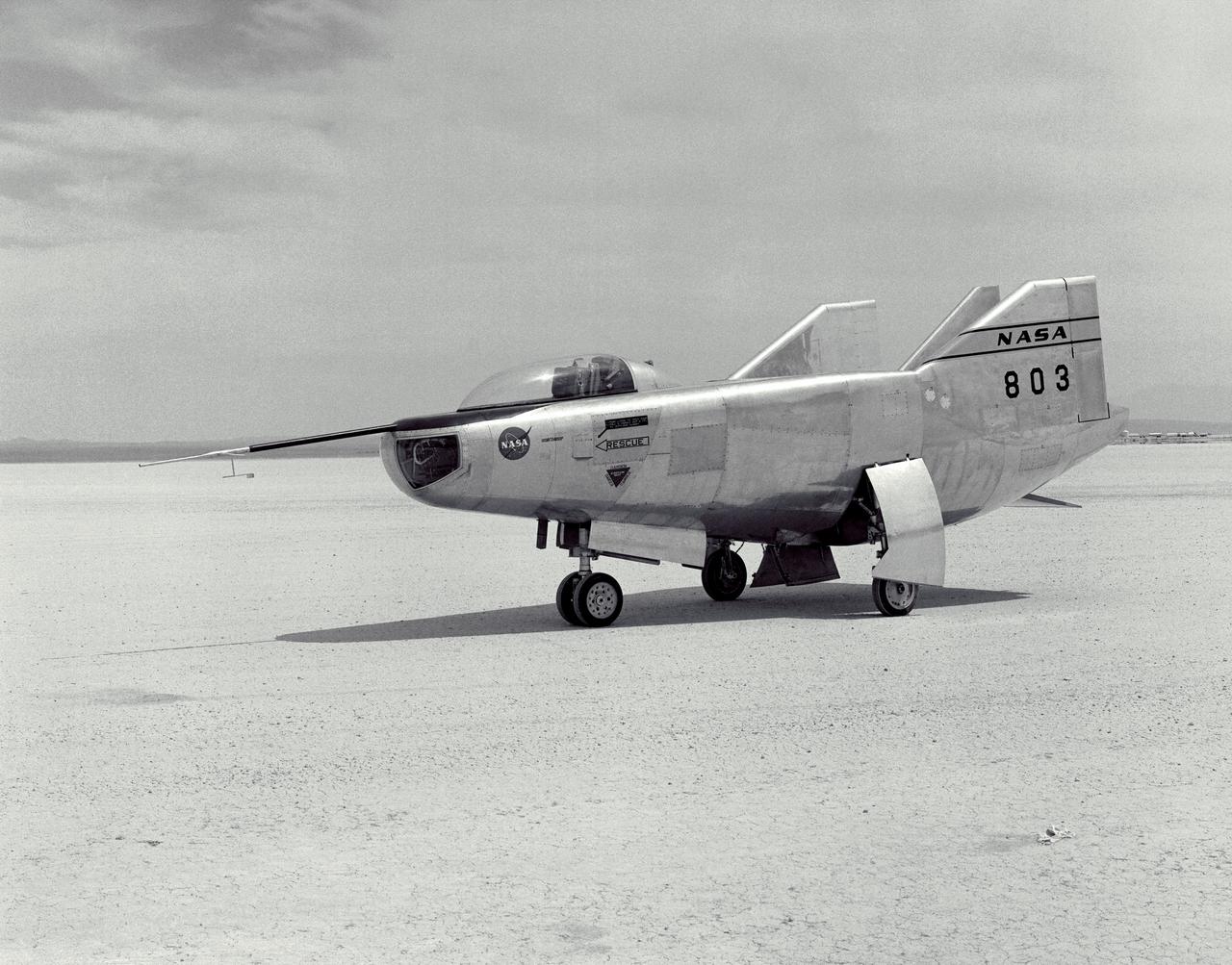
The M2-F3 Lifting Body is seen here on the lakebed at the NASA Flight Research Center (FRC--later the Dryden Flight Research Center), Edwards, California. After a three-year-long redesign and rebuilding effort, the M2-F3 was ready to fly. The May 1967 crash of the M2-F2 had damaged both the external skin and the internal structure of the lifting body. At first, it seemed that the vehicle had been irreparably damaged, but the original manufacturer, Northrop, did the repair work and returned the redesigned M2-F3 with a center fin for stability to the FRC.
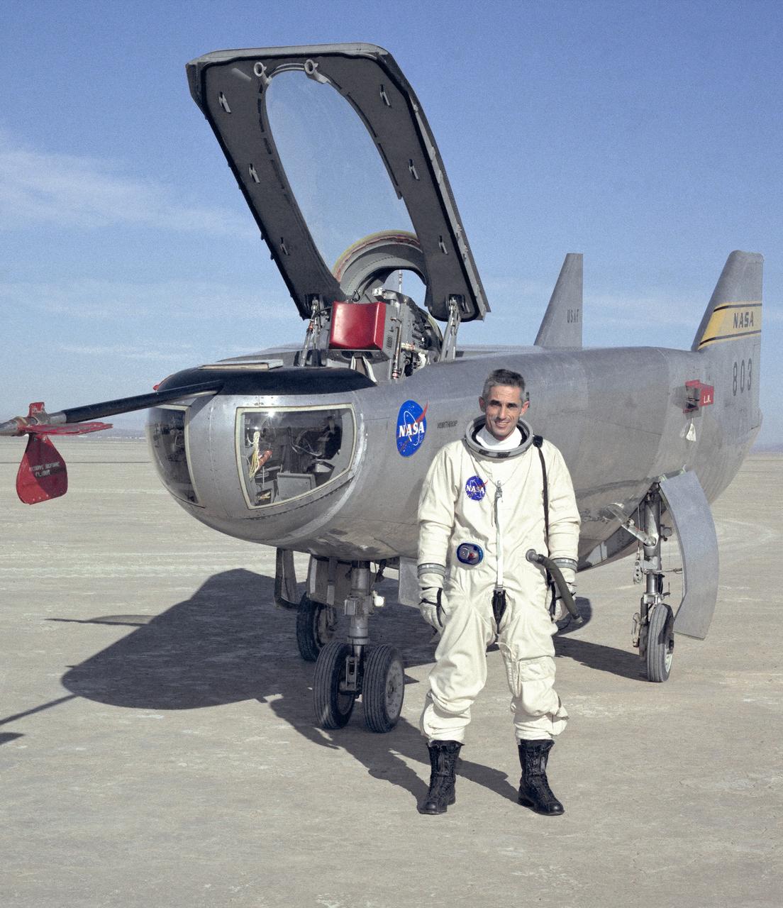
NASA research pilot John A. Manke is seen here in front of the M2-F3 Lifting Body. Manke was hired by NASA on May 25, 1962, as a flight research engineer. He was later assigned to the pilot's office and flew various support aircraft including the F-104, F5D, F-111 and C-47. After leaving the Marine Corps in 1960, Manke worked for Honeywell Corporation as a test engineer for two years before coming to NASA. He was project pilot on the X-24B and also flew the HL-10, M2-F3, and X-24A lifting bodies. John made the first supersonic flight of a lifting body and the first landing of a lifting body on a hard surface runway. Manke served as Director of the Flight Operations and Support Directorate at the Dryden Flight Research Center prior to its integration with Ames Research Center in October 1981. After this date John was named to head the joint Ames-Dryden Directorate of Flight Operations. He also served as site manager of the NASA Ames-Dryden Flight Research Facility. John is a member of the Society of Experimental Test Pilots. He retired on April 27, 1984.
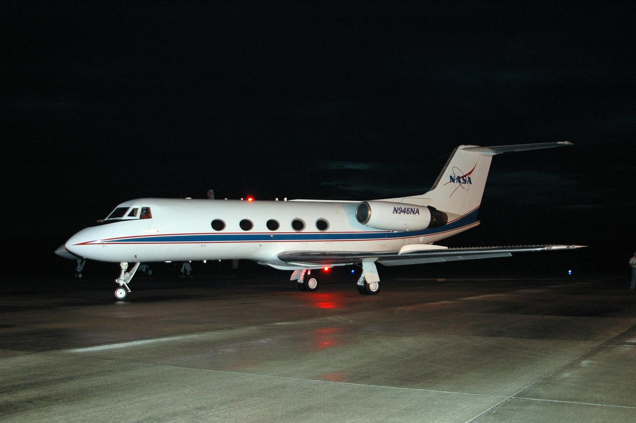
KENNEDY SPACE CENTER, FLA. - On NASA Kennedy Space Center's Shuttle Landing Facility, the Shuttle Training Aircraft taxis onto the runway. In the specially configured aircraft, STS-115 Commander Brent Jett and Pilot Christopher Ferguson will practice landing the shuttle. STA practice is part of launch preparations. The STA is a Grumman American Aviation-built Gulf Stream II jet that was modified to simulate an orbiter’s cockpit, motion and visual cues, and handling qualities. In flight, the STA duplicates the orbiter’s atmospheric descent trajectory from approximately 35,000 feet altitude to landing on a runway. Because the orbiter is unpowered during re-entry and landing, its high-speed glide must be perfectly executed the first time. Mission STS-115 is scheduled to lift off about 4:30 p.m. Aug. 27. The crew will deliver and install the P3/P4 segment to the port side of the integrated truss system on the International Space Station. The truss includes a new set of photovoltaic solar arrays. When unfurled to their full length of 240 feet, the arrays will provide additional power for the station in preparation for the delivery of international science modules over the next two years. The mission is expected to last 11 days and includes three scheduled spacewalks. Photo credit: NASA/Kim Shiflett
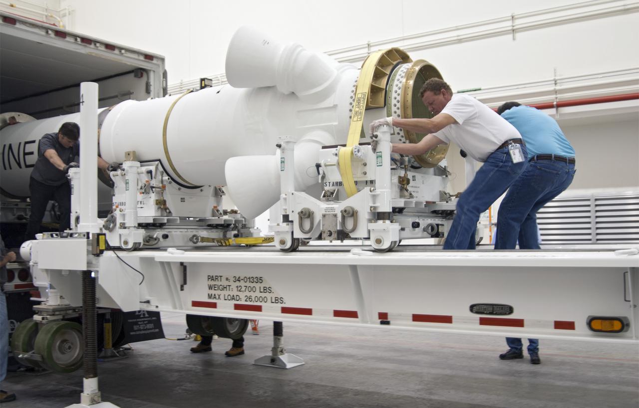
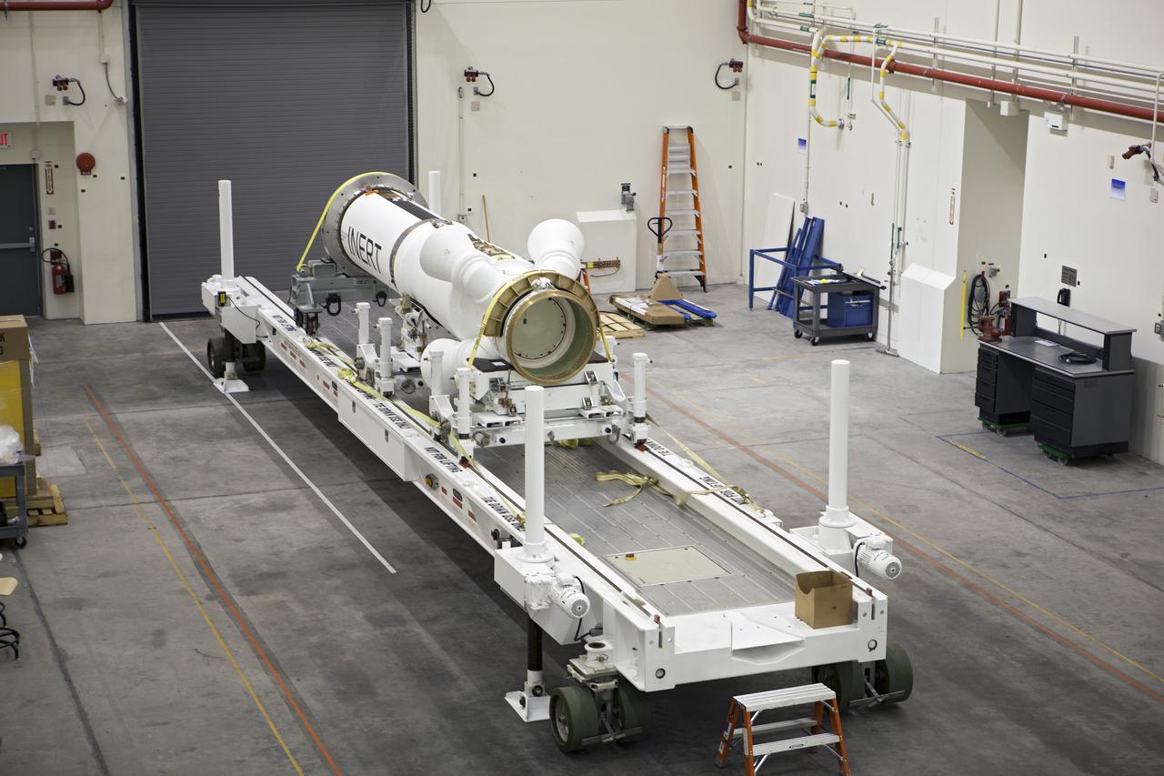
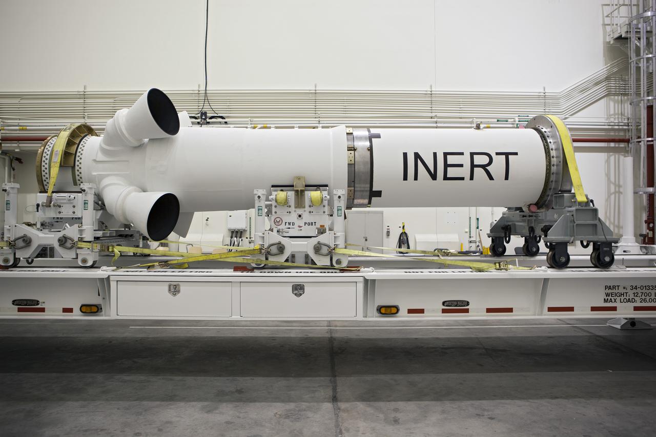
CAPE CANAVERAL, Fla. – At NASA’s Kennedy Space Center in Florida, technicians help remove the Alliant Techsystems, or ATK, launch abort motor from a truck after arrival at the Launch Abort System Facility. The test flight abort motor is for Exploration Flight Test 1, or EFT-1, of the agency’s Orion Multi-Purpose Crew Vehicle. It is part of Orion’s Launch Abort System, which is designed to safely pull the Orion crew module away from the launch vehicle in the event of an emergency on the launch pad or during the initial ascent of NASA’s Space Launch System, or SLS, rocket. The motor is configured with inert propellant. Orion is the exploration spacecraft designed to carry crews to space beyond low Earth orbit. It will provide emergency abort capability, sustain the crew during the space travel and provide safe re-entry from deep space return velocities. Orion’s first unpiloted test flight is scheduled to launch in 2014 atop a Delta IV rocket. A second uncrewed flight test is scheduled for 2017 on the SLS rocket. For more information, visit http:__www.nasa.gov_orion. Photo credit: NASA_Charisse Nahser
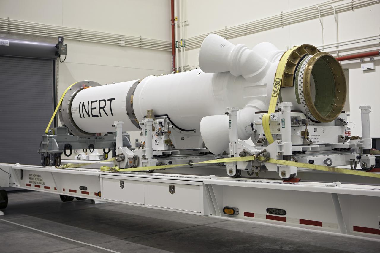
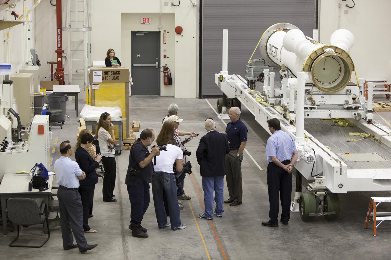
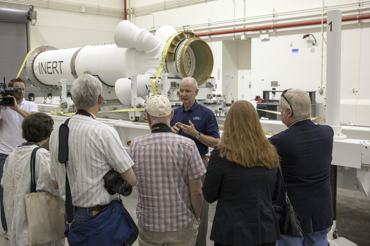
CAPE CANAVERAL, Fla. – At NASA’s Kennedy Space Center in Florida, members of the media viewed the Alliant Techsystems, or ATK, launch abort motor inside the Launch Abort System Facility. ATK’s abort motor is one of the components of Orion’s Launch Abort System, which will be used for Exploration Flight Test 1, or EFT-1. The system is designed to safely pull the Orion crew module away from the launch vehicle in the event of an emergency on the launch pad or during the initial ascent of NASA’s Space Launch System, or SLS, rocket. The test flight abort motor is configured with inert propellant. Orion is the exploration spacecraft designed to carry crews to space beyond low Earth orbit. It will provide emergency abort capability, sustain the crew during the space travel and provide safe re-entry from deep space return velocities. Orion’s first unpiloted test flight is scheduled to launch in 2014 atop a Delta IV rocket. A second uncrewed flight test is scheduled for 2017 on the SLS rocket. For more information, visit http:__www.nasa.gov_orion. Photo credit: NASA_Dimitri Gerondidakis
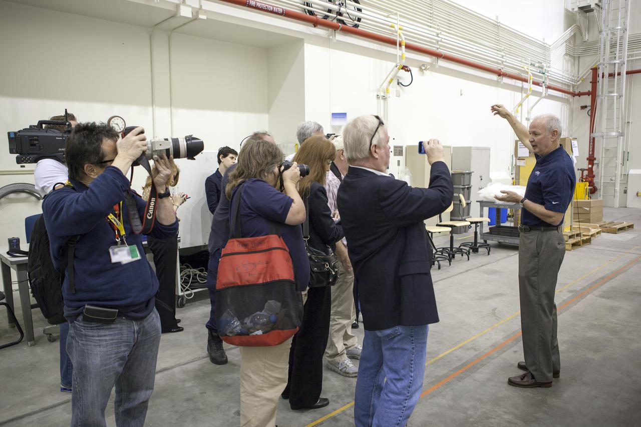
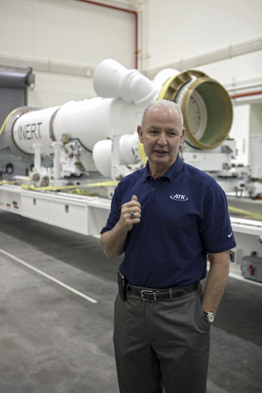
CAPE CANAVERAL, Fla. – At NASA’s Kennedy Space Center in Florida, Brian Duffy, the vice president and Johnson Space Center manager for Exploration Systems with ATK Aerospace Systems, talks with members of the media during a viewing of ATK’s launch abort motor inside the Launch Abort System Facility. The abort motor is one of the components of Orion’s Launch Abort System, which will be used for Exploration Flight Test 1, or EFT-1. The system is designed to safely pull the Orion crew module away from the launch vehicle in the event of an emergency on the launch pad or during the initial ascent of NASA’s Space Launch System, or SLS, rocket. The test flight abort motor is configured with inert propellant. Orion is the exploration spacecraft designed to carry crews to space beyond low Earth orbit. It will provide emergency abort capability, sustain the crew during the space travel and provide safe re-entry from deep space return velocities. Orion’s first unpiloted test flight is scheduled to launch in 2014 atop a Delta IV rocket. A second uncrewed flight test is scheduled for 2017 on the SLS rocket. For more information, visit http:__www.nasa.gov_orion. Photo credit: NASA_Dimitri Gerondidakis
CAPE CANAVERAL, Fla. – At NASA’s Kennedy Space Center in Florida, Brian Duffy, the vice president and Johnson Space Center manager for Exploration Systems with ATK Aerospace Systems, talks with members of the media during a viewing of ATK’s launch abort motor inside the Launch Abort System Facility. The abort motor is one of the components of Orion’s Launch Abort System, which will be used for Exploration Flight Test 1, or EFT-1. The system is designed to safely pull the Orion crew module away from the launch vehicle in the event of an emergency on the launch pad or during the initial ascent of NASA’s Space Launch System, or SLS, rocket. The test flight abort motor is configured with inert propellant. Orion is the exploration spacecraft designed to carry crews to space beyond low Earth orbit. It will provide emergency abort capability, sustain the crew during the space travel and provide safe re-entry from deep space return velocities. Orion’s first unpiloted test flight is scheduled to launch in 2014 atop a Delta IV rocket. A second uncrewed flight test is scheduled for 2017 on the SLS rocket. For more information, visit http:__www.nasa.gov_orion. Photo credit: NASA_Dimitri Gerondidakis
CAPE CANAVERAL, Fla. – At NASA’s Kennedy Space Center in Florida, members of the media viewed the Alliant Techsystems, or ATK, launch abort motor inside the Launch Abort System Facility. ATK’s abort motor is one of the components of Orion’s Launch Abort System, which will be used for Exploration Flight Test 1, or EFT-1. The system is designed to safely pull the Orion crew module away from the launch vehicle in the event of an emergency on the launch pad or during the initial ascent of NASA’s Space Launch System, or SLS, rocket. The test flight abort motor is configured with inert propellant. Orion is the exploration spacecraft designed to carry crews to space beyond low Earth orbit. It will provide emergency abort capability, sustain the crew during the space travel and provide safe re-entry from deep space return velocities. Orion’s first unpiloted test flight is scheduled to launch in 2014 atop a Delta IV rocket. A second uncrewed flight test is scheduled for 2017 on the SLS rocket. For more information, visit http:__www.nasa.gov_orion. Photo credit: NASA_Dimitri Gerondidakis
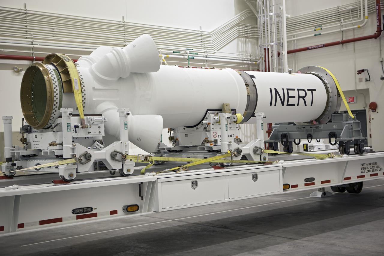
CAPE CANAVERAL, Fla. – At NASA’s Kennedy Space Center in Florida, members of the media viewed the Alliant Techsystems, or ATK, launch abort motor inside the Launch Abort System Facility. ATK’s abort motor is one of the components of Orion’s Launch Abort System, which will be used for Exploration Flight Test 1, or EFT-1. The system is designed to safely pull the Orion crew module away from the launch vehicle in the event of an emergency on the launch pad or during the initial ascent of NASA’s Space Launch System, or SLS, rocket. The test flight abort motor is configured with inert propellant. Orion is the exploration spacecraft designed to carry crews to space beyond low Earth orbit. It will provide emergency abort capability, sustain the crew during the space travel and provide safe re-entry from deep space return velocities. Orion’s first unpiloted test flight is scheduled to launch in 2014 atop a Delta IV rocket. A second uncrewed flight test is scheduled for 2017 on the SLS rocket. For more information, visit http:__www.nasa.gov_orion. Photo credit: NASA_Dimitri Gerondidakis
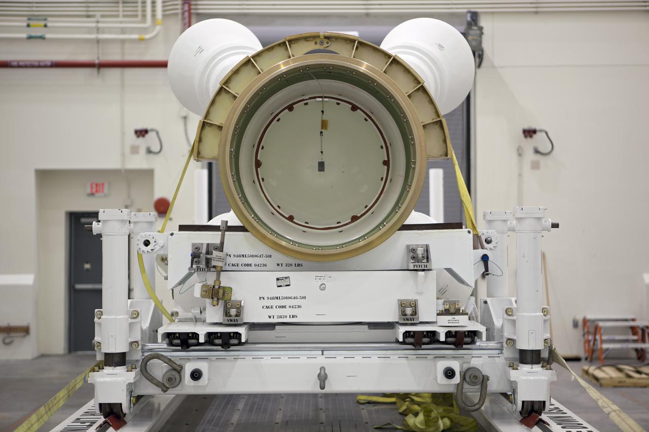
CAPE CANAVERAL, Fla. – At NASA’s Kennedy Space Center in Florida, members of the media viewed the Alliant Techsystems, or ATK, launch abort motor inside the Launch Abort System Facility. ATK’s abort motor is one of the components of Orion’s Launch Abort System, which will be used for Exploration Flight Test 1, or EFT-1. The system is designed to safely pull the Orion crew module away from the launch vehicle in the event of an emergency on the launch pad or during the initial ascent of NASA’s Space Launch System, or SLS, rocket. The test flight abort motor is configured with inert propellant. Orion is the exploration spacecraft designed to carry crews to space beyond low Earth orbit. It will provide emergency abort capability, sustain the crew during the space travel and provide safe re-entry from deep space return velocities. Orion’s first unpiloted test flight is scheduled to launch in 2014 atop a Delta IV rocket. A second uncrewed flight test is scheduled for 2017 on the SLS rocket. For more information, visit http:__www.nasa.gov_orion. Photo credit: NASA_Dimitri Gerondidakis
CAPE CANAVERAL, Fla. – At NASA’s Kennedy Space Center in Florida, Brian Duffy, the vice president and Johnson Space Center manager for Exploration Systems with ATK Aerospace Systems, talks with members of the media during a viewing of ATK’s launch abort motor inside the Launch Abort System Facility. The abort motor is one of the components of Orion’s Launch Abort System, which will be used for Exploration Flight Test 1, or EFT-1. The system is designed to safely pull the Orion crew module away from the launch vehicle in the event of an emergency on the launch pad or during the initial ascent of NASA’s Space Launch System, or SLS, rocket. The test flight abort motor is configured with inert propellant. Orion is the exploration spacecraft designed to carry crews to space beyond low Earth orbit. It will provide emergency abort capability, sustain the crew during the space travel and provide safe re-entry from deep space return velocities. Orion’s first unpiloted test flight is scheduled to launch in 2014 atop a Delta IV rocket. A second uncrewed flight test is scheduled for 2017 on the SLS rocket. For more information, visit http:__www.nasa.gov_orion. Photo credit: NASA_Dimitri Gerondidakis
CAPE CANAVERAL, Fla. – Inside the Launch Abort System Facility at NASA’s Kennedy Space Center in Florida, technicians have removed the Alliant Techsystems, or ATK, launch abort motor from a truck. The test flight launch abort motor is for Exploration Flight Test 1, or EFT-1, of the agency’s Orion Multi-Purpose Crew Vehicle. It is part of Orion’s Launch Abort System, which is designed to safely pull the Orion crew module away from the launch vehicle in the event of an emergency on the launch pad or during the initial ascent of NASA’s Space Launch System, or SLS, rocket. The motor is configured with inert propellant. Orion is the exploration spacecraft designed to carry crews to space beyond low Earth orbit. It will provide emergency abort capability, sustain the crew during the space travel and provide safe re-entry from deep space return velocities. Orion’s first unpiloted test flight is scheduled to launch in 2014 atop a Delta IV rocket. A second uncrewed flight test is scheduled for 2017 on the SLS rocket. For more information, visit http:__www.nasa.gov_orion. Photo credit: NASA_Charisse Nahser
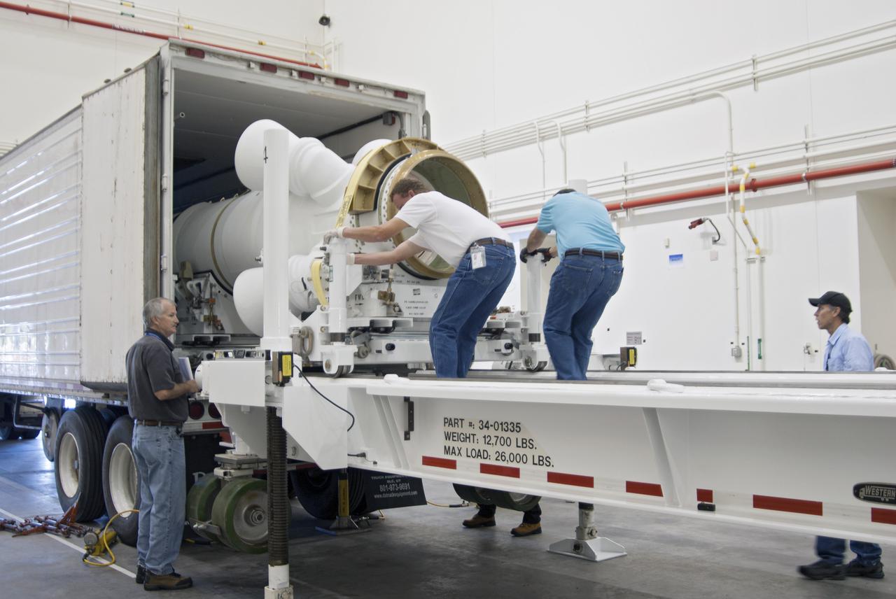
CAPE CANAVERAL, Fla. – At NASA’s Kennedy Space Center in Florida, technicians help remove the Alliant Techsystems, or ATK, launch abort motor from a truck after arrival at the Launch Abort System Facility. The test flight abort motor is for Exploration Flight Test 1, or EFT-1, of the agency’s Orion Multi-Purpose Crew Vehicle. It is part of Orion’s Launch Abort System, which is designed to safely pull the Orion crew module away from the launch vehicle in the event of an emergency on the launch pad or during the initial ascent of NASA’s Space Launch System, or SLS, rocket. The motor is configured with inert propellant. Orion is the exploration spacecraft designed to carry crews to space beyond low Earth orbit. It will provide emergency abort capability, sustain the crew during the space travel and provide safe re-entry from deep space return velocities. Orion’s first unpiloted test flight is scheduled to launch in 2014 atop a Delta IV rocket. A second uncrewed flight test is scheduled for 2017 on the SLS rocket. For more information, visit http:__www.nasa.gov_orion. Photo credit: NASA_Charisse Nahser
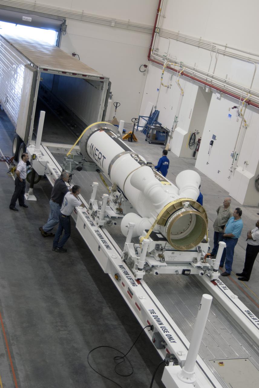
CAPE CANAVERAL, Fla. – At NASA’s Kennedy Space Center in Florida, the Alliant Techsystems, or ATK, launch abort motor arrives at the Launch Abort System Facility for Exploration Flight Test 1, or EFT-1, of the agency’s Orion Multi-Purpose Crew Vehicle. ATK’s abort motor is part of Orion’s Launch Abort System, which is designed to safely pull the Orion crew module away from the launch vehicle in the event of an emergency on the launch pad or during the initial ascent of NASA’s Space Launch System, or SLS, rocket. The test flight abort motor is configured with inert propellant. Orion is the exploration spacecraft designed to carry crews to space beyond low Earth orbit. It will provide emergency abort capability, sustain the crew during the space travel and provide safe re-entry from deep space return velocities. Orion’s first unpiloted test flight is scheduled to launch in 2014 atop a Delta IV rocket. A second uncrewed flight test is scheduled for 2017 on the SLS rocket. For more information, visit http:__www.nasa.gov_orion. Photo credit: NASA_Charisse Nahser
CAPE CANAVERAL, Fla. – At NASA’s Kennedy Space Center in Florida, Brian Duffy, the vice president and Johnson Space Center manager for Exploration Systems with ATK Aerospace Systems, talks with members of the media during a viewing of ATK’s launch abort motor inside the Launch Abort System Facility. The abort motor is one of the components of Orion’s Launch Abort System, which will be used for Exploration Flight Test 1, or EFT-1. The system is designed to safely pull the Orion crew module away from the launch vehicle in the event of an emergency on the launch pad or during the initial ascent of NASA’s Space Launch System, or SLS, rocket. The test flight abort motor is configured with inert propellant. Orion is the exploration spacecraft designed to carry crews to space beyond low Earth orbit. It will provide emergency abort capability, sustain the crew during the space travel and provide safe re-entry from deep space return velocities. Orion’s first unpiloted test flight is scheduled to launch in 2014 atop a Delta IV rocket. A second uncrewed flight test is scheduled for 2017 on the SLS rocket. For more information, visit http:__www.nasa.gov_orion. Photo credit: NASA_Dimitri Gerondidakis
CAPE CANAVERAL, Fla. – At NASA’s Kennedy Space Center in Florida, members of the media viewed the Alliant Techsystems, or ATK, launch abort motor inside the Launch Abort System Facility. ATK’s abort motor is one of the components of Orion’s Launch Abort System, which will be used for Exploration Flight Test 1, or EFT-1. The system is designed to safely pull the Orion crew module away from the launch vehicle in the event of an emergency on the launch pad or during the initial ascent of NASA’s Space Launch System, or SLS, rocket. The test flight abort motor is configured with inert propellant. Orion is the exploration spacecraft designed to carry crews to space beyond low Earth orbit. It will provide emergency abort capability, sustain the crew during the space travel and provide safe re-entry from deep space return velocities. Orion’s first unpiloted test flight is scheduled to launch in 2014 atop a Delta IV rocket. A second uncrewed flight test is scheduled for 2017 on the SLS rocket. For more information, visit http:__www.nasa.gov_orion. Photo credit: NASA_Dimitri Gerondidakis
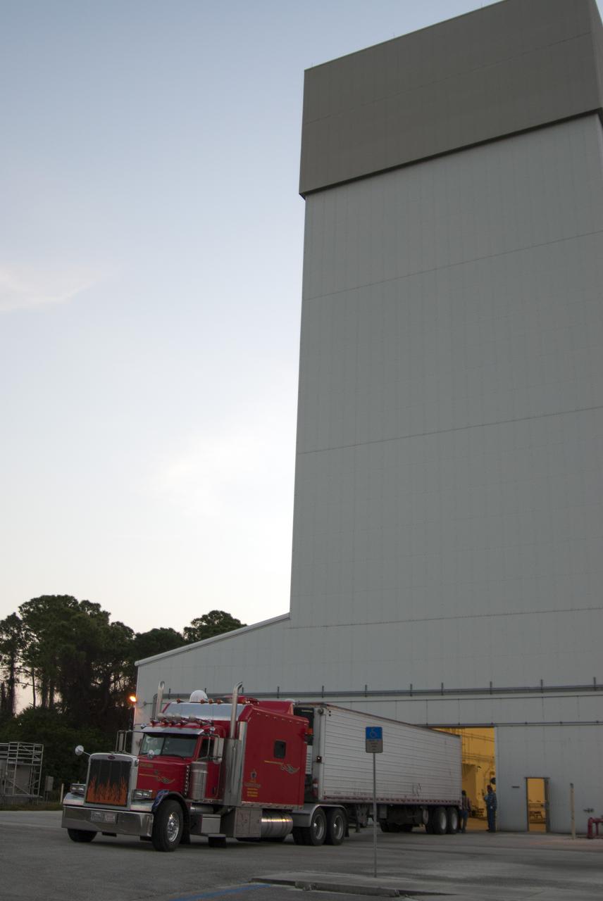
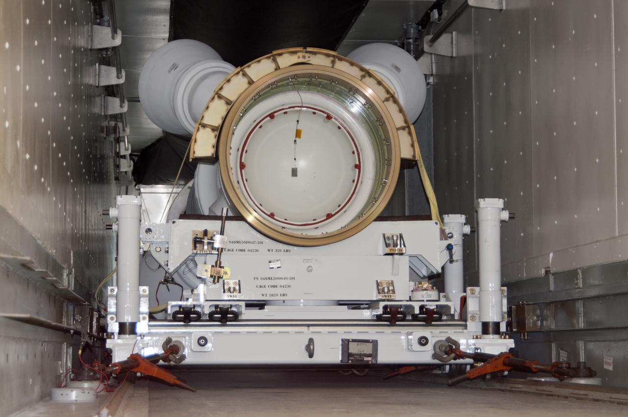
CAPE CANAVERAL, Fla. – At NASA’s Kennedy Space Center in Florida, a truck arrives at the Launch Abort System Facility with a launch abort motor from Alliant Techsystems, or ATK, for Exploration Flight Test 1, or EFT-1, of the agency’s Orion Multi-Purpose Crew Vehicle. ATK’s abort motor is part of Orion’s Launch Abort System, which is designed to safely pull the Orion crew module away from the launch vehicle in the event of an emergency on the launch pad or during the initial ascent of NASA’s Space Launch System, or SLS, rocket. The test flight abort motor is configured with inert propellant. Orion is the exploration spacecraft designed to carry crews to space beyond low Earth orbit. It will provide emergency abort capability, sustain the crew during the space travel and provide safe re-entry from deep space return velocities. Orion’s first unpiloted test flight is scheduled to launch in 2014 atop a Delta IV rocket. A second uncrewed flight test is scheduled for 2017 on the SLS rocket. For more information, visit http:__www.nasa.gov_orion. Photo credit: NASA_Charisse Nahser
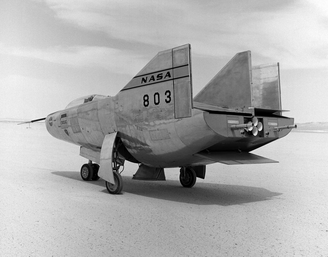
The M2-F3 Lifting Body is seen here on the lakebed next to the NASA Flight Research Center (later the Dryden Flight Research Center), Edwards, California. Redesigned and rebuilt from the M2-F2, the M2-F3 featured as its most visible change a center fin for greater stability. While the M2-F3 was still demanding to fly, the center fin eliminated the high risk of pilot induced oscillation (PIO) that was characteristic of the M2-F2.
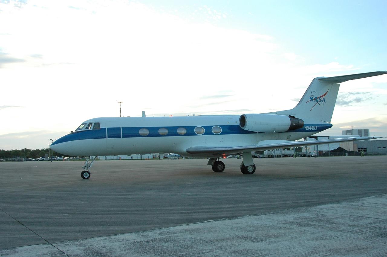
KENNEDY SPACE CENTER, FLA. - A Shuttle Training Aircraft (STA) taxis into the parking area of KSC's Shuttle Landing Facility. In the specially configured aircraft, STS-115 Commander Brent Jett and Pilot Christopher Ferguson practiced landing the shuttle this morning. STA practice is part of launch preparations. The STA is a Grumman American Aviation-built Gulf Stream II jet that was modified to simulate an orbiter’s cockpit, motion and visual cues, and handling qualities. In flight, the STA duplicates the orbiter’s atmospheric descent trajectory from approximately 35,000 feet altitude to landing on a runway. Because the orbiter is unpowered during re-entry and landing, its high-speed glide must be perfectly executed the first time. Mission STS-115 is scheduled to lift off about 12:29 p.m. Sept. 6. Mission managers cancelled Atlantis' first launch campaign due to a lightning strike at the pad and the passage of Tropical Storm Ernesto along Florida's east coast. The mission will deliver and install the 17-and-a-half-ton P3/P4 truss segment to the port side of the integrated truss system on the orbital outpost. The truss includes a new set of photovoltaic solar arrays. When unfurled to their full length of 240 feet, the arrays will provide additional power for the station in preparation for the delivery of international science modules over the next two years. STS-115 is expected to last 11 days and includes three scheduled spacewalks. Photo credit: NASA/Kim Shiflett
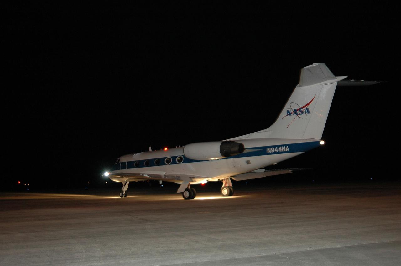
KENNEDY SPACE CENTER, FLA. - In the early morning hours on NASA Kennedy Space Center's Shuttle Landing Facility, the Shuttle Training Aircraft taxis onto the runway. In the specially configured aircraft, STS-115 Commander Brent Jett and Pilot Christopher Ferguson are practicing landing the shuttle. STA practice is part of launch preparations. The STA is a Grumman American Aviation-built Gulf Stream II jet that was modified to simulate an orbiter’s cockpit, motion and visual cues, and handling qualities. In flight, the STA duplicates the orbiter’s atmospheric descent trajectory from approximately 35,000 feet altitude to landing on a runway. Because the orbiter is unpowered during re-entry and landing, its high-speed glide must be perfectly executed the first time. Mission STS-115 is scheduled to lift off about 12:29 p.m. Sept. 6. Mission managers cancelled Atlantis' first launch campaign due to a lightning strike at the pad and the passage of Tropical Storm Ernesto along Florida's east coast. The mission will deliver and install the 17-and-a-half-ton P3/P4 truss segment to the port side of the integrated truss system on the orbital outpost. The truss includes a new set of photovoltaic solar arrays. When unfurled to their full length of 240 feet, the arrays will provide additional power for the station in preparation for the delivery of international science modules over the next two years. STS-115 is expected to last 11 days and includes three scheduled spacewalks. Photo credit: NASA/Kim Shiflett
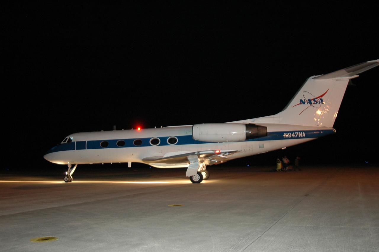
KENNEDY SPACE CENTER, FLA. - In the early morning hours on NASA Kennedy Space Center's Shuttle Landing Facility, the Shuttle Training Aircraft taxis onto the runway. In the specially configured aircraft, STS-115 Commander Brent Jett and Pilot Christopher Ferguson are practicing landing the shuttle. STA practice is part of launch preparations. The STA is a Grumman American Aviation-built Gulf Stream II jet that was modified to simulate an orbiter’s cockpit, motion and visual cues, and handling qualities. In flight, the STA duplicates the orbiter’s atmospheric descent trajectory from approximately 35,000 feet altitude to landing on a runway. Because the orbiter is unpowered during re-entry and landing, its high-speed glide must be perfectly executed the first time. Mission STS-115 is scheduled to lift off about 12:29 p.m. Sept. 6. Mission managers cancelled Atlantis' first launch campaign due to a lightning strike at the pad and the passage of Tropical Storm Ernesto along Florida's east coast. The mission will deliver and install the 17-and-a-half-ton P3/P4 truss segment to the port side of the integrated truss system on the orbital outpost. The truss includes a new set of photovoltaic solar arrays. When unfurled to their full length of 240 feet, the arrays will provide additional power for the station in preparation for the delivery of international science modules over the next two years. STS-115 is expected to last 11 days and includes three scheduled spacewalks. Photo credit: NASA/Kim Shiflett
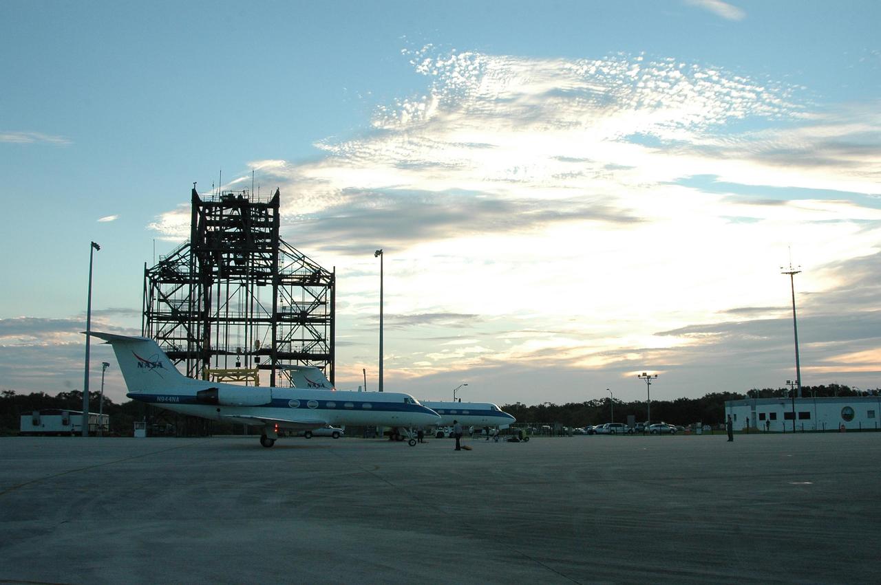
KENNEDY SPACE CENTER, FLA. - A Shuttle Training Aircraft (STA) is positioned in the parking area of KSC's Shuttle Landing Facility. In the specially configured aircraft, STS-115 Commander Brent Jett and Pilot Christopher Ferguson practiced landing the shuttle this morning. The space shuttle's Mate-Demate Device is seen in the background. STA practice is part of launch preparations. The STA is a Grumman American Aviation-built Gulf Stream II jet that was modified to simulate an orbiter’s cockpit, motion and visual cues, and handling qualities. In flight, the STA duplicates the orbiter’s atmospheric descent trajectory from approximately 35,000 feet altitude to landing on a runway. Because the orbiter is unpowered during re-entry and landing, its high-speed glide must be perfectly executed the first time. Mission STS-115 is scheduled to lift off about 12:29 p.m. Sept. 6. Mission managers cancelled Atlantis' first launch campaign due to a lightning strike at the pad and the passage of Tropical Storm Ernesto along Florida's east coast. The mission will deliver and install the 17-and-a-half-ton P3/P4 truss segment to the port side of the integrated truss system on the orbital outpost. The truss includes a new set of photovoltaic solar arrays. When unfurled to their full length of 240 feet, the arrays will provide additional power for the station in preparation for the delivery of international science modules over the next two years. STS-115 is expected to last 11 days and includes three scheduled spacewalks. Photo credit: NASA/Kim Shiflett
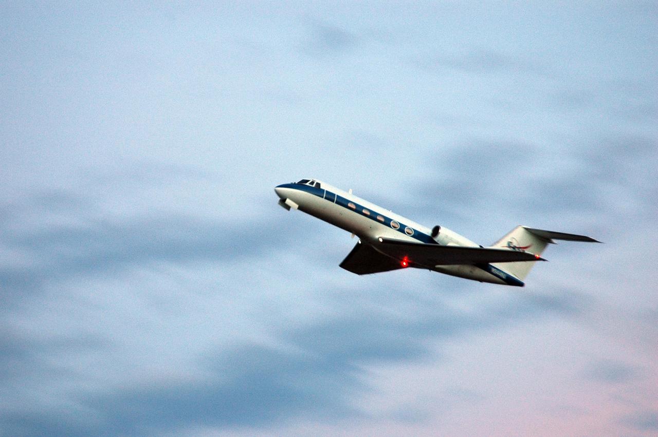
KENNEDY SPACE CENTER, FLA. - On NASA Kennedy Space Center's Shuttle Landing Facility, the Shuttle Training Aircraft takes to the skies. In the specially configured aircraft, STS-115 Commander Brent Jett and Pilot Christopher Ferguson are practicing landing the shuttle. STA practice is part of launch preparations. The STA is a Grumman American Aviation-built Gulf Stream II jet that was modified to simulate an orbiter’s cockpit, motion and visual cues, and handling qualities. In flight, the STA duplicates the orbiter’s atmospheric descent trajectory from approximately 35,000 feet altitude to landing on a runway. Because the orbiter is unpowered during re-entry and landing, its high-speed glide must be perfectly executed the first time. Mission STS-115 is scheduled to lift off about 12:29 p.m. Sept. 6. Mission managers cancelled Atlantis' first launch campaign due to a lightning strike at the pad and the passage of Tropical Storm Ernesto along Florida's east coast. The mission will deliver and install the 17-and-a-half-ton P3/P4 truss segment to the port side of the integrated truss system on the orbital outpost. The truss includes a new set of photovoltaic solar arrays. When unfurled to their full length of 240 feet, the arrays will provide additional power for the station in preparation for the delivery of international science modules over the next two years. STS-115 is expected to last 11 days and includes three scheduled spacewalks. Photo credit: NASA/Kim Shiflett