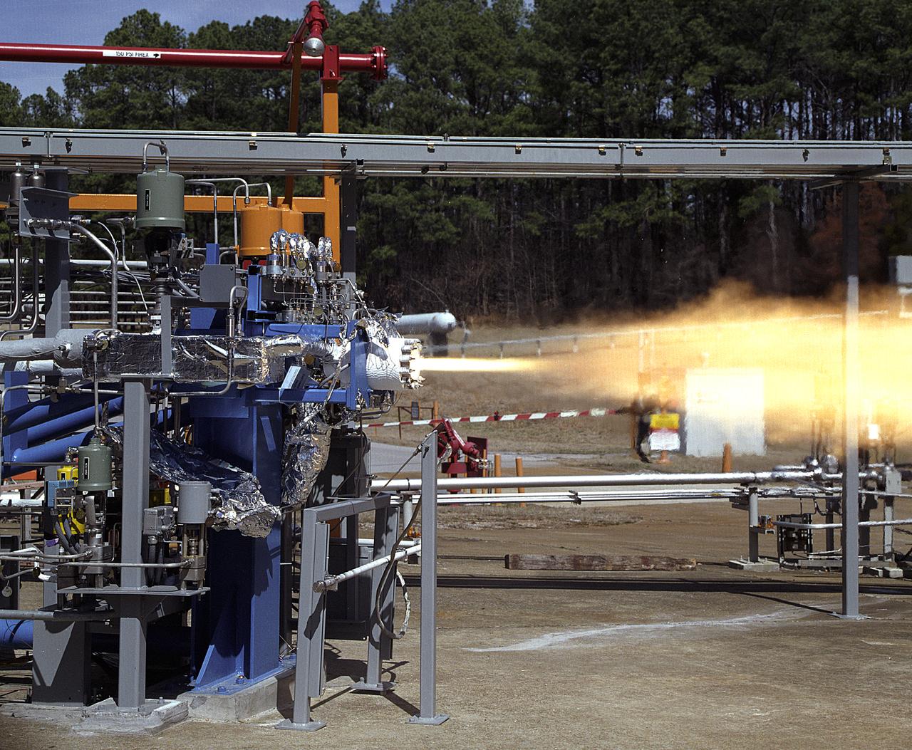
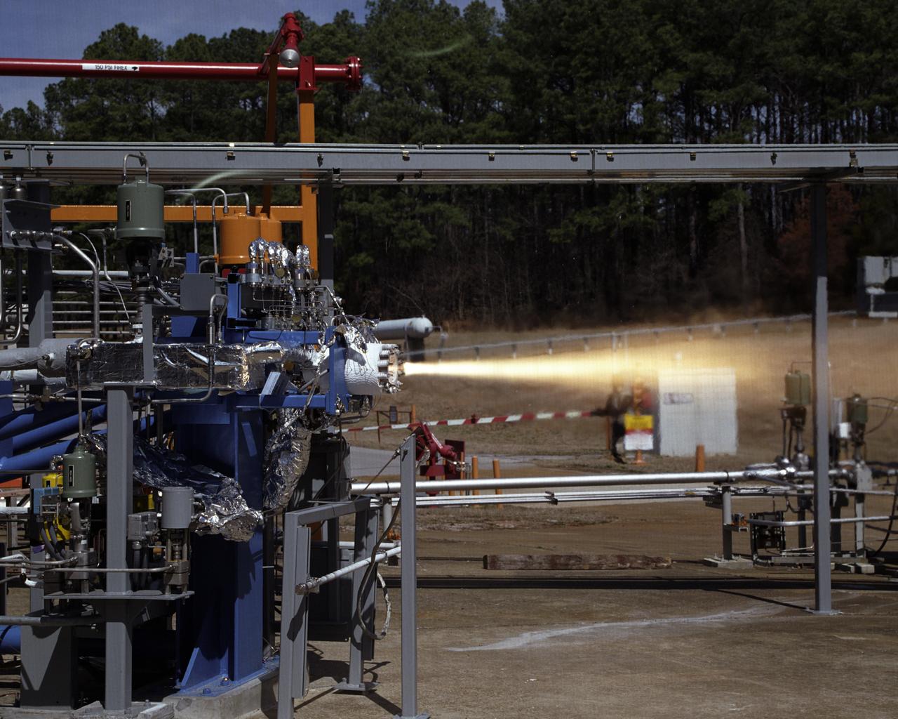
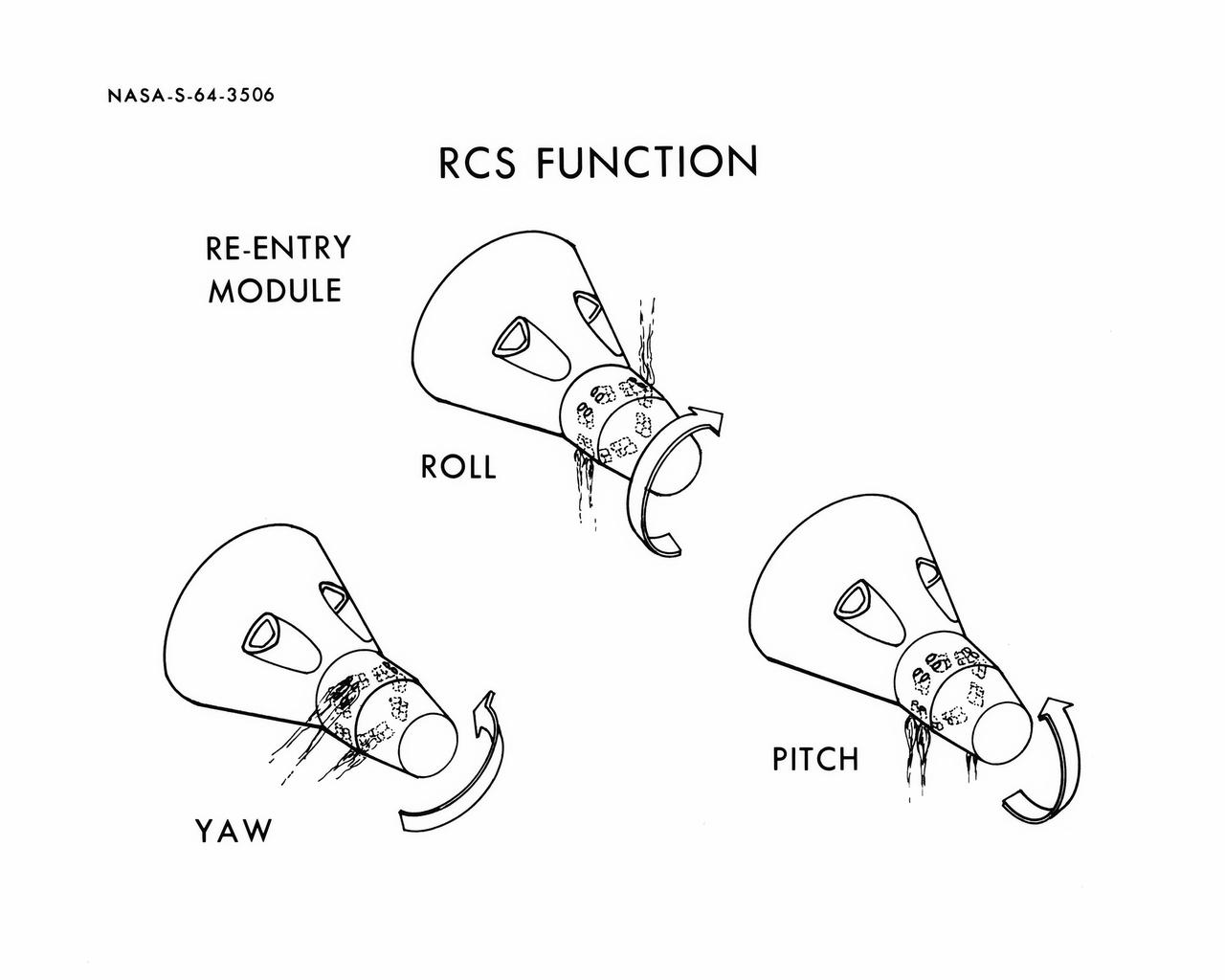
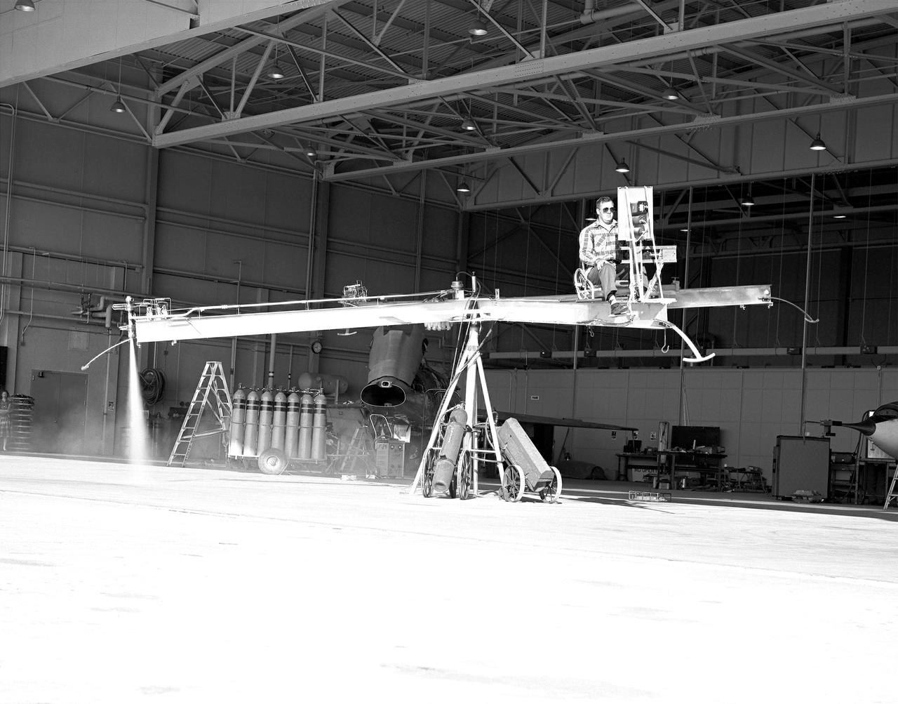
Bell X-1B fitted with a reaction control system on the lakebed
Bell X-1B fitted with a reaction control system on the lakebed.
Bell X-1B fitted with a reaction control system on the lakebed
STS039-27-016 (28 April-6 May 1991) --- The Space Shuttle Discovery fires reaction control subsystem (RCS) thrusters in this 35mm frame, taken from inside the crew cabin.  Seen in Discovery's payload bay are the tops of cannisters on the STP-1 payload, configured on the STS 39 Hitchhiker carrier; and the Air Force Program (AFP) 675 package.  AFP-675 consists of the Cryogenic Infrared Radiance Instrumentation for Shuttle (CIRRIS)-1A; Far Ultraviolet Camera (FAR-UV) Experiment; Horizon Ultraviolet Program (HUP); Quadruple Ion Neutral Mass Spectrometer (QINMS); and the Uniformly Redundant Array (URA).
STS-39 OV-103 reaction control system (RCS) jets fire during onorbit maneuver
NASA's Marshall Space Flight Center (MSFC) in Huntsville, Alabama, has begun a series of engine tests on the Reaction Control Engine developed by TRW Space and Electronics for NASA's Space Launch Initiative (SLI). SLI is a technology development effort aimed at improving the safety, reliability, and cost effectiveness of space travel for reusable launch vehicles. The engine in this photo, the first engine tested at MSFC that includes SLI technology, was tested for two seconds at a chamber pressure of 185 pounds per square inch absolute (psia). Propellants used were liquid oxygen as an oxidizer and liquid hydrogen as fuel. Designed to maneuver vehicles in orbit, the engine is used as an auxiliary propulsion system for docking, reentry, fine-pointing, and orbit transfer while the vehicle is in orbit. The Reaction Control Engine has two unique features. It uses nontoxic chemicals as propellants, which creates a safer environment with less maintenance and quicker turnaround time between missions, and it operates in dual thrust modes, combining two engine functions into one engine. The engine operates at both 25 and 1,000 pounds of force, reducing overall propulsion weight and allowing vehicles to easily maneuver in space. The force of low level thrust allows the vehicle to fine-point maneuver and dock, while the force of the high level thrust is used for reentry, orbital transfer, and course positioning.
Research Technology
The X-1B reaction control system thrusters are tested in 1958 and later proven on the X-15 as a way to control a vehicle in the absence of dynamic pressure.
NASA Armstrong Celebrates 70 Years of Flight Research
Engineers at the Marshall Space Flight Center (MSFC) have begun a series of engine tests on a new breed of space propulsion: a Reaction Control Engine developed for the Space Launch Initiative (SLI). The engine, developed by TRW Space and Electronics of Redondo Beach, California, is an auxiliary propulsion engine designed to maneuver vehicles in orbit. It is used for docking, reentry, attitude control, and fine-pointing while the vehicle is in orbit. The engine uses nontoxic chemicals as propellants, a feature that creates a safer environment for ground operators, lowers cost, and increases efficiency with less maintenance and quicker turnaround time between missions. Testing includes 30 hot-firings. This photograph shows the first engine test performed at MSFC that includes SLI technology. Another unique feature of the Reaction Control Engine is that it operates at dual thrust modes, combining two engine functions into one engine. The engine operates at both 25 and 1,000 pounds of force, reducing overall propulsion weight and allowing vehicles to easily maneuver in space. The low-level thrust of 25 pounds of force allows the vehicle to fine-point maneuver and dock while the high-level thrust of 1,000 pounds of force is used for reentry, orbit transfer, and coarse positioning. SLI is a NASA-wide research and development program, managed by the MSFC, designed to improve safety, reliability, and cost effectiveness of space travel for second generation reusable launch vehicles.
Research Technology
Behind three Douglas D-558-IIs is the B-29 launch aircraft. Under its right wing is the world’s first ground-based reaction control system motion simulator.
A Full Flightline at Armstrong
Reaction Control System Thruster examined in the electron optics lab Near Field Emission Scanning Electron Microscope
GRC-2005-C-01164
KENNEDY SPACE CENTER, FLA. --  Inside NASA Kennedy Space Center’s Orbiter Processing Facility Bay 1, workers secure the overhead crane to the sling placed round the forward reaction control system that will be installed on Atlantis.  When ready, the shuttle equipment will be lifted for installation.   The forward reaction control system is located in the forward fuselage nose area.  During ascent of the space shuttle, it provides the thrust for attitude (rotational) maneuvers (pitch, yaw and roll) and for small velocity changes along the orbiter axis (translation maneuvers).
KSC-05pd2568
KENNEDY SPACE CENTER, FLA. --  Inside NASA Kennedy Space Center’s Orbiter Processing Facility Bay 1, workers move the sling into place around the forward reaction control system that will be installed on Atlantis.  When ready, the shuttle equipment will be lifted for installation. The forward reaction control system is located in the forward fuselage nose area.  During ascent of the space shuttle, it provides the thrust for attitude (rotational) maneuvers (pitch, yaw and roll) and for small velocity changes along the orbiter axis (translation maneuvers).
KSC-05pd2566
KENNEDY SPACE CENTER, FLA. --  Inside NASA Kennedy Space Center’s Orbiter Processing Facility Bay 1, workers make adjustments to the sling being placed round the forward reaction control system that will be installed on Atlantis. When ready, the shuttle equipment will be lifted for installation.  The forward reaction control system is located in the forward fuselage nose area.  During ascent of the space shuttle, it provides the thrust for attitude (rotational) maneuvers (pitch, yaw and roll) and for small velocity changes along the orbiter axis (translation maneuvers).
KSC-05pd2567
KENNEDY SPACE CENTER, FLA. --  Inside NASA Kennedy Space Center’s Orbiter Processing Facility Bay 1, workers get ready to lift the sling placed round the forward reaction control system that will be installed on Atlantis.  The forward reaction control system is located in the forward fuselage nose area.  During ascent of the space shuttle, it provides the thrust for attitude (rotational) maneuvers (pitch, yaw and roll) and for small velocity changes along the orbiter axis (translation maneuvers).
KSC-05pd2569
S64-03506 (1964) --- Diagrams shows Gemini spacecraft functions of the thrusters in the Gemini spacecraft's re-entry control system. Thrusters may be fired in various combinations to cause yaw, roll and pitch.
Diagrams of Spacecraft Reaction Control System (RCS) Function
NACA High-Speed Flight Station test pilot Stan Butchart flying the Iron Cross, the mechanical reaction control simulator. High-pressure nitrogen gas expanded selectively, by the pilot, through the small reaction control thrusters maneuvered the Iron Cross through the three axes. The exhaust plume can be seen from the aft thruster. The tanks containing the gas can be seen on the cart at the base of the pivot point of the Iron Cross. NACA technicians built the iron-frame simulator, which matched the inertia ratios of the Bell X-1B airplane, installing six jet nozzles to control the movement about the three axes of pitch, roll, and yaw.
E-2578
(PCG) Protein Crystal Growth Renin. Enzyme produced by the kidneys, plays a major role in the chemical reaction that controls blood pressure. Principal Investigator on STS-26 was Charles Bugg.
Microgravity
G.E. Fan-in-fuselage model (lifting). 3/4 rear view of fan at low G.P. position.  Lift fan on variable height strut for ground effects studies with reaction control. T-Tail.
General Electric Fan-In-Fuselage Lifting Model in the 40x80 Foot Wind Tunnel at NASA Ames.
NASA Associate Administrator for Space Flight Joseph Rothenberg addresses attendees at a ribbon cutting for the new Checkout and Launch Control System (CLCS) at the Hypergolic Maintenance Facility (HMF). The CLCS was declared operational in a ribbon cutting ceremony earlier. The new control room will be used to process the Orbital Maneuvering System pods and Forward Reaction Control System modules at the HMF. This hardware is removed from Space Shuttle orbiters and routinely taken to the HMF for checkout and servicing
KSC-00pp1243
KSC Director Roy Bridges addresses attendees at a ribbon cutting for the new Checkout and Launch Control System (CLCS) at the Hypergolic Maintenance Facility (HMF). The CLCS was declared operational in a ribbon cutting ceremony earlier. The new control room will be used to process the Orbital Maneuvering System pods and Forward Reaction Control System modules at the HMF. This hardware is removed from Space Shuttle orbiters and routinely taken to the HMF for checkout and servicing
KSC00pp1242
KSC Director Roy Bridges addresses attendees at a ribbon cutting for the new Checkout and Launch Control System (CLCS) at the Hypergolic Maintenance Facility (HMF). The CLCS was declared operational in a ribbon cutting ceremony earlier. The new control room will be used to process the Orbital Maneuvering System pods and Forward Reaction Control System modules at the HMF. This hardware is removed from Space Shuttle orbiters and routinely taken to the HMF for checkout and servicing
KSC-00pp1242
S66-41852 (1966) --- Spacecraft 012 looking toward -Y axis during installation of heat shield. Note uprighting system compressor in aft bay, at right, and Reaction Control System (RCS) valve module panel, center of photo.
COMPRESSOR - UPRIGHTING SYSTEM - APOLLO MANUFACTURING - SPACECRAFT (S/C)-102 COMMAND MODULE (CM) - NORTH AMERICAN AVIATION (NAA), CA
STS059-58-018 (9-20 April 1994) --- Part of the Space Shuttle Endeavour and its Space Radar Laboratory (SRL-1) payload are backdropped against a colorful display of the Southern Lights (aurora australis). The vehicle was firing a reaction control subsystem thruster (below center) when the 35mm image was exposed.
Endeavour and its SRL-1 payload backdropped against the Southern Lights
STS106-352-009 (8-20 September 2000) --- Astronaut Terrence W. Wilcutt, STS-106 mission commander, performs a firing of the reaction control system on the flight deck of the Space Shuttle Atlantis. Earth’s horizon is visible through the commander’s window.
Commander Wilcutt works at the commander's workstation during STS-106
KENNEDY SPACE CENTER, FLA. -  In the Vertical Processing Facility, the replacement Reaction Wheel Actuator for the Hubble Space Telescope is moved from its shipping container.   Part of Hubble's Pointing Control System, the actuators receiving information from sensors and physically adjust Hubble's position and orientation so that Hubble can view the required celestial bodies.  The reaction wheels work by rotating a large flywheel up to 3000 rpm or braking it to exchange momentum with the spacecraft which will make Hubble turn.   The RWA is part of the payload on mission STS-109, the Hubble Servicing Mission, scheduled to launch Feb. 28, 2002
KSC-02pd0094
KENNEDY SPACE CENTER, FLA. --  The replacement Reaction Wheel Actuator for the Hubble Space Telescope arrives at the Vertical Processing Facility. Part of Hubble's Pointing Control System, the actuators receiving information from sensors and physically adjust Hubble's position and orientation so that Hubble can view the required celestial bodies.  The reaction wheels work by rotating a large flywheel up to 3000 rpm or braking it to exchange momentum with the spacecraft which will make Hubble turn.   The RWA is part of the payload on mission STS-109, the Hubble Servicing Mission, scheduled to launch Feb. 28, 2002
KSC-02pd0093
KENNEDY SPACE CENTER, FLA. - Workers in the Vertical Processing Facility check the position of the Hubble Space Telescope's replacement Reaction Wheel Actuator on the Large Orbital Protective Enclosure (LOPE), which is contained in the Multi-Use Lightweight Equipment (MULE) for flight.  Part of Hubble's Pointing Control System, the actuators receiving information from sensors and physically adjust Hubble's position and orientation so that Hubble can view the required celestial bodies.  The reaction wheels work by rotating a large flywheel up to 3000 rpm or braking it to exchange momentum with the spacecraft which will make Hubble turn.   The RWA is part of the payload on mission STS-109, the Hubble Servicing Mission, scheduled to launch Feb. 28, 2002
KSC-02pd0097
KENNEDY SPACE CENTER, FLA. -  Workers in the Vertical Processing Facility maneuver the replacement Reaction Wheel Actuator for the Hubble Space Telescope into position on the Large Orbital Protective Enclosure (LOPE), which is contained in the Multi-Use Lightweight Equipment (MULE) for flight.  Part of Hubble's Pointing Control System, the actuators receiving information from sensors and physically adjust Hubble's position and orientation so that Hubble can view the required celestial bodies.  The reaction wheels work by rotating a large flywheel up to 3000 rpm or braking it to exchange momentum with the spacecraft which will make Hubble turn.   The RWA is part of the payload on mission STS-109, the Hubble Servicing Mission, scheduled to launch Feb. 28, 2002
KSC-02pd0095
KENNEDY SPACE CENTER, FLA. - Workers in the Vertical Processing Facility check the position of the Hubble Space Telescope's replacement Reaction Wheel Actuator on the Large Orbital Protective Enclosure (LOPE), which is contained in the Multi-Use Lightweight Equipment (MULE) for flight.  Part of Hubble's Pointing Control System, the actuators receiving information from sensors and physically adjust Hubble's position and orientation so that Hubble can view the required celestial bodies.  The reaction wheels work by rotating a large flywheel up to 3000 rpm or braking it to exchange momentum with the spacecraft which will make Hubble turn.   The RWA is part of the payload on mission STS-109, the Hubble Servicing Mission, scheduled to launch Feb. 28, 2002
KSC-02PD-0096
KENNEDY SPACE CENTER, FLA. -- Workers in the Vertical Processing Facility check the attachment of the the Hubble Space Telescope's replacement Reaction Wheel Actuator on the Large Orbital Protective Enclosure (LOPE), which is contained in the Multi-Use Lightweight Equipment (MULE) for flight.  Part of Hubble's Pointing Control System, the actuators receiving information from sensors and physically adjust Hubble's position and orientation so that Hubble can view the required celestial bodies.  The reaction wheels work by rotating a large flywheel up to 3000 rpm or braking it to exchange momentum with the spacecraft which will make Hubble turn.   The RWA is part of the payload on mission STS-109, the Hubble Servicing Mission, scheduled to launch Feb. 28, 2002
KSC-02pd0098
KENNEDY SPACE CENTER, FLA. --   In NASA Kennedy Space Center’s Orbiter Processing Facility Bay 1, technicians check details for the installation of the forward reaction control system on Atlantis (behind them).  The control system fits just behind the nose cone and provides the thrust for attitude (rotational) maneuvers (pitch, yaw and roll) and for small velocity changes along the orbiter axis (translation maneuvers).  Processing of Atlantis is under way for mission STS-115, the 19th flight to the International Space Station.
KSC-05pd2572
KENNEDY SPACE CENTER, FLA. --   In NASA Kennedy Space Center’s Orbiter Processing Facility Bay 1, workers are installing the forward reaction control system on Atlantis.  The control system fits just behind the nose cone and provides the thrust for attitude (rotational) maneuvers (pitch, yaw and roll) and for small velocity changes along the orbiter axis (translation maneuvers).  Processing of Atlantis is under way for mission STS-115, the 19th flight to the International Space Station.
KSC-05pd2570
KENNEDY SPACE CENTER, FLA. --   In NASA Kennedy Space Center’s Orbiter Processing Facility Bay 1, installation of the forward reaction control system on Atlantis is complete.  The control system fits just behind the nose cone and provides the thrust for attitude (rotational) maneuvers (pitch, yaw and roll) and for small velocity changes along the orbiter axis (translation maneuvers).  Processing of Atlantis is under way for mission STS-115, the 19th flight to the International Space Station.
KSC-05pd2574
KENNEDY SPACE CENTER, FLA. --   In NASA Kennedy Space Center’s Orbiter Processing Facility Bay 1, workers are installing the forward reaction control system on Atlantis.   The control system fits just behind the nose cone and provides the thrust for attitude (rotational) maneuvers (pitch, yaw and roll) and for small velocity changes along the orbiter axis (translation maneuvers).  Processing of Atlantis is under way for mission STS-115, the 19th flight to the International Space Station.
KSC-05pd2571
KENNEDY SPACE CENTER, FLA. --   In NASA Kennedy Space Center’s Orbiter Processing Facility Bay 1, a technician inspects a point of installation of the forward reaction control system on Atlantis. The control system fits just behind the nose cone and provides the thrust for attitude (rotational) maneuvers (pitch, yaw and roll) and for small velocity changes along the orbiter axis (translation maneuvers).  Processing of Atlantis is under way for mission STS-115, the 19th flight to the International Space Station.
KSC-05pd2573
KENNEDY SPACE CENTER, FLA. - In the Orbiter Processing Facility, one of two orbital maneuvering system (OMS) pods is being moved for installation on Atlantis.  The OMS pods are attached to the upper aft fuselage left and right sides. Fabricated primarily of graphite epoxy composite and aluminum, each pod is 21.8 feet long and 11.37 feet wide at its aft end and 8.41 feet wide at its forward end, with a surface area of approximately 435 square feet. Each pod houses the Reaction Control System propulsion components used for inflight maneuvering and is attached to the aft fuselage with 11 bolts.
KENNEDY SPACE CENTER, FLA. - In the Orbiter Processing Facility, one of two orbital maneuvering system (OMS) pods is being moved for installation on Atlantis. The OMS pods are attached to the upper aft fuselage left and right sides. Fabricated primarily of graphite epoxy composite and aluminum, each pod is 21.8 feet long and 11.37 feet wide at its aft end and 8.41 feet wide at its forward end, with a surface area of approximately 435 square feet. Each pod houses the Reaction Control System propulsion components used for inflight maneuvering and is attached to the aft fuselage with 11 bolts.
KENNEDY SPACE CENTER, FLA. - In the Orbiter Processing Facility, technicians move an orbital maneuvering system (OMS) pod into the correct position on Atlantis. The OMS pod is one of two that are attached to the upper aft fuselage left and right sides. Fabricated primarily of graphite epoxy composite and aluminum, each pod is 21.8 feet long and 11.37 feet wide at its aft end and 8.41 feet wide at its forward end, with a surface area of approximately 435 square feet. Each pod houses the Reaction Control System propulsion components used for inflight maneuvering and is attached to the aft fuselage with 11 bolts.
KENNEDY SPACE CENTER, FLA. - In the Orbiter Processing Facility, an orbital maneuvering system (OMS) pod is moved into place on Atlantis.  It is one of two OMS pods attached to the upper aft fuselage left and right sides. Fabricated primarily of graphite epoxy composite and aluminum, each pod is 21.8 feet long and 11.37 feet wide at its aft end and 8.41 feet wide at its forward end, with a surface area of approximately 435 square feet. Each pod houses the Reaction Control System propulsion components used for inflight maneuvering and is attached to the aft fuselage with 11 bolts.
KENNEDY SPACE CENTER, FLA. - In the Orbiter Processing Facility, an orbital maneuvering system (OMS) pod is moved into place on Atlantis. It is one of two OMS pods attached to the upper aft fuselage left and right sides. Fabricated primarily of graphite epoxy composite and aluminum, each pod is 21.8 feet long and 11.37 feet wide at its aft end and 8.41 feet wide at its forward end, with a surface area of approximately 435 square feet. Each pod houses the Reaction Control System propulsion components used for inflight maneuvering and is attached to the aft fuselage with 11 bolts.
KENNEDY SPACE CENTER, FLA. - In the Orbiter Processing Facility, workers discuss the next step in moving the orbital maneuvering system (OMS) pod behind them.  The OMS pod will be installed on Atlantis.  Two OMS pods are attached to the upper aft fuselage left and right sides. Fabricated primarily of graphite epoxy composite and aluminum, each pod is 21.8 feet long and 11.37 feet wide at its aft end and 8.41 feet wide at its forward end, with a surface area of approximately 435 square feet. Each pod houses the Reaction Control System propulsion components used for inflight maneuvering and is attached to the aft fuselage with 11 bolts.
KENNEDY SPACE CENTER, FLA. - In the Orbiter Processing Facility, workers discuss the next step in moving the orbital maneuvering system (OMS) pod behind them. The OMS pod will be installed on Atlantis. Two OMS pods are attached to the upper aft fuselage left and right sides. Fabricated primarily of graphite epoxy composite and aluminum, each pod is 21.8 feet long and 11.37 feet wide at its aft end and 8.41 feet wide at its forward end, with a surface area of approximately 435 square feet. Each pod houses the Reaction Control System propulsion components used for inflight maneuvering and is attached to the aft fuselage with 11 bolts.
KENNEDY SPACE CENTER, FLA. -  In the Orbiter Processing Facility, one of two orbital maneuvering system (OMS) pods is lifted off its stand to move it toward Atlantis for installation. The OMS pods are attached to the upper aft fuselage left and right sides. Fabricated primarily of graphite epoxy composite and aluminum, each pod is 21.8 feet long and 11.37 feet wide at its aft end and 8.41 feet wide at its forward end, with a surface area of approximately 435 square feet. Each pod houses the Reaction Control System propulsion components used for inflight maneuvering and is attached to the aft fuselage with 11 bolts.
KENNEDY SPACE CENTER, FLA. - In the Orbiter Processing Facility, one of two orbital maneuvering system (OMS) pods is lifted off its stand to move it toward Atlantis for installation. The OMS pods are attached to the upper aft fuselage left and right sides. Fabricated primarily of graphite epoxy composite and aluminum, each pod is 21.8 feet long and 11.37 feet wide at its aft end and 8.41 feet wide at its forward end, with a surface area of approximately 435 square feet. Each pod houses the Reaction Control System propulsion components used for inflight maneuvering and is attached to the aft fuselage with 11 bolts.
KENNEDY SPACE CENTER, FLA. - In the Orbiter Processing Facility, technicians make final adjustments to the orbital maneuvering system (OMS) pod being installed on Atlantis.   The OMS pod is one of two that are attached to the upper aft fuselage left and right sides. Fabricated primarily of graphite epoxy composite and aluminum, each pod is 21.8 feet long and 11.37 feet wide at its aft end and 8.41 feet wide at its forward end, with a surface area of approximately 435 square feet. Each pod houses the Reaction Control System propulsion components used for inflight maneuvering and is attached to the aft fuselage with 11 bolts.
KENNEDY SPACE CENTER, FLA. - In the Orbiter Processing Facility, technicians make final adjustments to the orbital maneuvering system (OMS) pod being installed on Atlantis. The OMS pod is one of two that are attached to the upper aft fuselage left and right sides. Fabricated primarily of graphite epoxy composite and aluminum, each pod is 21.8 feet long and 11.37 feet wide at its aft end and 8.41 feet wide at its forward end, with a surface area of approximately 435 square feet. Each pod houses the Reaction Control System propulsion components used for inflight maneuvering and is attached to the aft fuselage with 11 bolts.
KENNEDY SPACE CENTER, FLA. - In the Orbiter Processing Facility, one of two orbital maneuvering system (OMS) pods is being moved for installation on Atlantis.  The OMS pods are attached to the upper aft fuselage left and right sides. Fabricated primarily of graphite epoxy composite and aluminum, each pod is 21.8 feet long and 11.37 feet wide at its aft end and 8.41 feet wide at its forward end, with a surface area of approximately 435 square feet. Each pod houses the Reaction Control System propulsion components used for inflight maneuvering and is attached to the aft fuselage with 11 bolts.
KENNEDY SPACE CENTER, FLA. - In the Orbiter Processing Facility, one of two orbital maneuvering system (OMS) pods is being moved for installation on Atlantis. The OMS pods are attached to the upper aft fuselage left and right sides. Fabricated primarily of graphite epoxy composite and aluminum, each pod is 21.8 feet long and 11.37 feet wide at its aft end and 8.41 feet wide at its forward end, with a surface area of approximately 435 square feet. Each pod houses the Reaction Control System propulsion components used for inflight maneuvering and is attached to the aft fuselage with 11 bolts.
KENNEDY SPACE CENTER, FLA. - In the Orbiter Processing Facility, technicians make adjustments to the orbital maneuvering system (OMS) pod being installed on Atlantis.   The OMS pod is one of two that are attached to the upper aft fuselage left and right sides. Fabricated primarily of graphite epoxy composite and aluminum, each pod is 21.8 feet long and 11.37 feet wide at its aft end and 8.41 feet wide at its forward end, with a surface area of approximately 435 square feet. Each pod houses the Reaction Control System propulsion components used for inflight maneuvering and is attached to the aft fuselage with 11 bolts.
KENNEDY SPACE CENTER, FLA. - In the Orbiter Processing Facility, technicians make adjustments to the orbital maneuvering system (OMS) pod being installed on Atlantis. The OMS pod is one of two that are attached to the upper aft fuselage left and right sides. Fabricated primarily of graphite epoxy composite and aluminum, each pod is 21.8 feet long and 11.37 feet wide at its aft end and 8.41 feet wide at its forward end, with a surface area of approximately 435 square feet. Each pod houses the Reaction Control System propulsion components used for inflight maneuvering and is attached to the aft fuselage with 11 bolts.
KENNEDY SPACE CENTER, FLA. -  In the Orbiter Processing Facility, an orbital maneuvering system (OMS) pod is moved closer to Atlantis for installation.  Two OMS pods are attached to the upper aft fuselage left and right sides. Fabricated primarily of graphite epoxy composite and aluminum, each pod is 21.8 feet long and 11.37 feet wide at its aft end and 8.41 feet wide at its forward end, with a surface area of approximately 435 square feet. Each pod houses the Reaction Control System propulsion components used for inflight maneuvering and is attached to the aft fuselage with 11 bolts.
KENNEDY SPACE CENTER, FLA. - In the Orbiter Processing Facility, an orbital maneuvering system (OMS) pod is moved closer to Atlantis for installation. Two OMS pods are attached to the upper aft fuselage left and right sides. Fabricated primarily of graphite epoxy composite and aluminum, each pod is 21.8 feet long and 11.37 feet wide at its aft end and 8.41 feet wide at its forward end, with a surface area of approximately 435 square feet. Each pod houses the Reaction Control System propulsion components used for inflight maneuvering and is attached to the aft fuselage with 11 bolts.
KENNEDY SPACE CENTER, FLA. -  In the Orbiter Processing Facility, an orbital maneuvering system (OMS) pod is suspended in air as it is moved toward Atlantis for installation.  Two OMS pods are attached to the upper aft fuselage left and right sides. Fabricated primarily of graphite epoxy composite and aluminum, each pod is 21.8 feet long and 11.37 feet wide at its aft end and 8.41 feet wide at its forward end, with a surface area of approximately 435 square feet. Each pod houses the Reaction Control System propulsion components used for inflight maneuvering and is attached to the aft fuselage with 11 bolts.
KENNEDY SPACE CENTER, FLA. - In the Orbiter Processing Facility, an orbital maneuvering system (OMS) pod is suspended in air as it is moved toward Atlantis for installation. Two OMS pods are attached to the upper aft fuselage left and right sides. Fabricated primarily of graphite epoxy composite and aluminum, each pod is 21.8 feet long and 11.37 feet wide at its aft end and 8.41 feet wide at its forward end, with a surface area of approximately 435 square feet. Each pod houses the Reaction Control System propulsion components used for inflight maneuvering and is attached to the aft fuselage with 11 bolts.
KENNEDY SPACE CENTER, FLA. -  In the Orbiter Processing Facility, technicians move an orbital maneuvering system (OMS) pod into the correct position on Atlantis. The OMS pod is one of two that are attached to the upper aft fuselage left and right sides. Fabricated primarily of graphite epoxy composite and aluminum, each pod is 21.8 feet long and 11.37 feet wide at its aft end and 8.41 feet wide at its forward end, with a surface area of approximately 435 square feet. Each pod houses the Reaction Control System propulsion components used for inflight maneuvering and is attached to the aft fuselage with 11 bolts.
KENNEDY SPACE CENTER, FLA. - In the Orbiter Processing Facility, technicians move an orbital maneuvering system (OMS) pod into the correct position on Atlantis. The OMS pod is one of two that are attached to the upper aft fuselage left and right sides. Fabricated primarily of graphite epoxy composite and aluminum, each pod is 21.8 feet long and 11.37 feet wide at its aft end and 8.41 feet wide at its forward end, with a surface area of approximately 435 square feet. Each pod houses the Reaction Control System propulsion components used for inflight maneuvering and is attached to the aft fuselage with 11 bolts.
KENNEDY SPACE CENTER, FLA. - In the Orbiter Processing Facility, an orbital maneuvering system (OMS) pod is moved into place on Atlantis.  It is one of two OMS pods attached to the upper aft fuselage left and right sides. Fabricated primarily of graphite epoxy composite and aluminum, each pod is 21.8 feet long and 11.37 feet wide at its aft end and 8.41 feet wide at its forward end, with a surface area of approximately 435 square feet. Each pod houses the Reaction Control System propulsion components used for inflight maneuvering and is attached to the aft fuselage with 11 bolts.
KENNEDY SPACE CENTER, FLA. - In the Orbiter Processing Facility, an orbital maneuvering system (OMS) pod is moved into place on Atlantis. It is one of two OMS pods attached to the upper aft fuselage left and right sides. Fabricated primarily of graphite epoxy composite and aluminum, each pod is 21.8 feet long and 11.37 feet wide at its aft end and 8.41 feet wide at its forward end, with a surface area of approximately 435 square feet. Each pod houses the Reaction Control System propulsion components used for inflight maneuvering and is attached to the aft fuselage with 11 bolts.
The ribbon is cut and the new Checkout and Launch Control System (CLCS) declared operational. Those taking part in the ceremony are (from left) Joseph Rothenberg, NASA Associate Administrator for Space Flight; Pam Gillespie, from Rep. Dave Weldon's office; Roy Bridges, Kennedy Space Center director; Dave King, director of Shuttle Processing; Retha Hart, deputy associate director, Spaceport Technology Management Office; and Ron Dittemore, manager, Space Shuttle Program. The new control room will be used to process the Orbital Maneuvering System pods and Forward Reaction Control System modules at the HMF. This hardware is removed from Space Shuttle orbiters and routinely taken to the HMF for checkout and servicing
KSC-00pp1244
KSC Director Roy Bridges (center) and guests view the new Checkout and Launch Control System (CLCS) at the Hypergolic Maintenance Facility (HMF). Looking on next to him (left) is NASA Associate Administrator for Space Flight Joseph Rothenberg and Pam Gillespie (far right), from Rep. Dave Weldon’s office. The CLCS was declared operational in a ribbon cutting ceremony earlier. The new control room will be used to process the Orbital Maneuvering System pods and Forward Reaction Control System modules at the HMF. This hardware is removed from Space Shuttle orbiters and routinely taken to the HMF for checkout and servicing
KSC-00pp1245
The ribbon is cut and the new Checkout and Launch Control System (CLCS) declared operational. Those taking part in the ceremony are (from left) Joseph Rothenberg, NASA Associate Administrator for Space Flight; Pam Gillespie, from Rep. Dave Weldon's office; Roy Bridges, Kennedy Space Center director; Dave King, director of Shuttle Processing; Retha Hart, deputy associate director, Spaceport Technology Management Office; and Ron Dittemore, manager, Space Shuttle Program. The new control room will be used to process the Orbital Maneuvering System pods and Forward Reaction Control System modules at the HMF. This hardware is removed from Space Shuttle orbiters and routinely taken to the HMF for checkout and servicing
KSC00pp1244
KSC Director Roy Bridges (center) and guests view the new Checkout and Launch Control System (CLCS) at the Hypergolic Maintenance Facility (HMF). Looking on next to him (left) is NASA Associate Administrator for Space Flight Joseph Rothenberg and Pam Gillespie (far right), from Rep. Dave Weldon’s office. The CLCS was declared operational in a ribbon cutting ceremony earlier. The new control room will be used to process the Orbital Maneuvering System pods and Forward Reaction Control System modules at the HMF. This hardware is removed from Space Shuttle orbiters and routinely taken to the HMF for checkout and servicing
KSC00pp1245
KENNEDY SPACE CENTER, FLA. -- Clyde Parrish, a NASA/KSC engineer, explains how the fertilizer scrubber control panel (center) works to turn nitrogen tetroxide vapor into fertilizer, potassium hydroxide. Parrish developed the system, which uses a "scrubber," to capture nitrogen tetroxide vapor that develops as a by-product when it is transferred from ground storage tanks into the Shuttle storage tanks. Nitrogen tetroxide is used as the oxidizer for the hypergolic propellant in the Shuttle's on-orbit reaction control system. The scrubber then uses hydrogen peroxide to produce nitric acid, which, after adding potassium hydroxide, converts to potassium nitrate. The resulting fertilizer will be used on the orange groves that KSC leases to outside companies
KSC00pp0511
KENNEDY SPACE CENTER, FLA. -- Clyde Parrish, a NASA/KSC engineer, explains how the fertilizer scrubber control panel (center) works to turn nitrogen tetroxide vapor into fertilizer, potassium hydroxide. Parrish developed the system, which uses a "scrubber," to capture nitrogen tetroxide vapor that develops as a by-product when it is transferred from ground storage tanks into the Shuttle storage tanks. Nitrogen tetroxide is used as the oxidizer for the hypergolic propellant in the Shuttle's on-orbit reaction control system. The scrubber then uses hydrogen peroxide to produce nitric acid, which, after adding potassium hydroxide, converts to potassium nitrate. The resulting fertilizer will be used on the orange groves that KSC leases to outside companies
KSC-00pp0511
S73-37030 (November 1973) --- The procedures for repairing the coolant system aboard the Airlock Module of the Skylab space station in Earth orbit are discussed by flight controllers in the Mission Operations Control Room in the Mission Control Center at Johnson Space Center. Skylab 4 flight director Neil Hutchinson is on the right. Astronaut Russell L. Schweickart is wearing the sports shirt. Astronaut Bruce McCandless II, a Skylab 4 CAPCOM, is seated next to Schweickart. Items of equipment in the foreground are similar to components of a special coolant re-servicing kit which was taken to Earth orbit by the Skylab 4 crewmen. The kit consists of a tank containing 42 pounds of COOLANOL, a series of saddle valves, bolts and spacers, and leak-check hoses. The re-supply tank is a modified command module reaction control subsystem (RCS) fuel tank. Photo credit: NASA
SKYLAB (SL)-4 - POSTLAUNCH - JSC
KSC Director Roy Bridges (right) views the new Checkout and Launch Control System (CLCS) at the Hypergolic Maintenance Facility (HMF). Looking on (left to right)are NASA Associate Administrator for Space Flight Joseph Rothenberg, United Space Alliance Lead IPT Frank Norris, KSC Deputy Center Director Jim Jennings, and Deputy Director of External Relations & Business Development Joe Gordon (behind Bridges). At the controls is Charles Novak, HMF programmer, United Space Alliance. The CLCS was declared operational in a ribbon cutting ceremony earlier. The new control room will be used to process the Orbital Maneuvering System pods and Forward Reaction Control System modules at the HMF. This hardware is removed from Space Shuttle orbiters and routinely taken to the HMF for checkout and servicing
KSC00pp1241
KSC Director Roy Bridges (right) views the new Checkout and Launch Control System (CLCS) at the Hypergolic Maintenance Facility (HMF). Looking on (left to right)are NASA Associate Administrator for Space Flight Joseph Rothenberg, United Space Alliance Lead IPT Frank Norris, KSC Deputy Center Director Jim Jennings, and Deputy Director of External Relations & Business Development Joe Gordon (behind Bridges). At the controls is Charles Novak, HMF programmer, United Space Alliance. The CLCS was declared operational in a ribbon cutting ceremony earlier. The new control room will be used to process the Orbital Maneuvering System pods and Forward Reaction Control System modules at the HMF. This hardware is removed from Space Shuttle orbiters and routinely taken to the HMF for checkout and servicing
KSC-00pp1241
CAPE CANAVERAL, Fla. – The forward reaction control system, or FRCS, will be removed from space shuttle Endeavour's forward fuselage nose area in NASA Kennedy Space Center's Orbiter Processing Facility 2.  The FRCS provides the thrust for attitude (rotational) maneuvers (pitch, yaw and roll) and for small velocity changes along the orbiter axis (translation maneuvers). Endeavour is designated as the shuttle for the STS-130 mission, targeted for launch in February 2010.  Photo credit: NASA/Jack Pfaller
KSC-2009-4792
KENNEDY SPACE CENTER, FLA.  - In the Orbiter Processing Facility, the Forward Reaction Control System (FRCS) is lifted by an overhead crane for installation in Discovery.  Located in the forward fuselage nose area, the FRCS provides the thrust for attitude (rotational) maneuvers (pitch, yaw and roll) and for small velocity changes along the orbiter axis (translation maneuvers).  Discovery is designated as the Return to Flight vehicle for mission STS-114, no earlier than March 2005.
KSC-04pd1331
KENNEDY SPACE CENTER, FLA. -    In Orbiter Processing Facility Bay 1, technicians work on the Forward Reaction Control System (FRCS) of space shuttle Atlantis as it sits in the transfer aisle prior to installation.  The FRCS provides the thrust for attitude (rotational) maneuvers (pitch, yaw and roll) and for small velocity changes along the orbiter axis (translation maneuvers).  Processing of Atlantis is under way for mission STS-115, the 19th flight to the International Space Station.
KSC-05pd2546
CAPE CANAVERAL, Fla. – The forward reaction control system, or FRCS, will be removed from space shuttle Endeavour's forward fuselage nose area in NASA Kennedy Space Center's Orbiter Processing Facility 2.  The FRCS provides the thrust for attitude (rotational) maneuvers (pitch, yaw and roll) and for small velocity changes along the orbiter axis (translation maneuvers). Endeavour is designated as the shuttle for the STS-130 mission, targeted for launch in February 2010.  Photo credit: NASA/Jack Pfaller
KSC-2009-4791
KENNEDY SPACE CENTER, FLA.  - In the Orbiter Processing Facility, the Forward Reaction Control System (FRCS) is lowered toward Discovery’s forward fuselage nose area where it will be installed.  The FRCS provides the thrust for attitude (rotational) maneuvers (pitch, yaw and roll) and for small velocity changes along the orbiter axis (translation maneuvers).  Discovery is designated as the Return to Flight vehicle for mission STS-114, no earlier than March 2005.
KSC-04pd1332
STS080-360-002 (19 Nov.-7 Dec. 1996) --- From the commander's station on the port side of the space shuttle Columbia's forward flight deck, astronaut Kenneth D. Cockrell prepares for a minor firing of Reaction Control System (RCS) engines during operations with the Wake Shield Facility (WSF). The activity was recorded with a 35mm camera on flight day seven. The commander is attired in a liquid-cooled biological garment.
Cockrell and Rominger go through de-orbit preparations in the flight deck
KENNEDY SPACE CENTER, FLA. -  In the Orbiter Processing Facility, the left-hand Orbital Maneuvering System (OMS) pod  is maneuvered toward the engine interfaces on the orbiter Discovery for installation.  The Orbital Maneuvering System provides the thrust for orbit insertion, orbit circularization, orbit transfer, rendezvous, deorbit, abort to orbit and abort once around.  It can provide up to 1,000 pounds of propellant to the aft reaction control system.  Each pod contains one OMS engine and the hardware needed to pressurize, store and distribute the propellants to perform the velocity maneuvers.
KSC-04pd0948
CAPE CANAVERAL, Fla. – In NASA Kennedy Space Center's Orbiter Processing Facility 2, workers remove the forward reaction control system, or FRCS, from space shuttle Endeavour's forward fuselage nose area. The FRCS provides the thrust for attitude (rotational) maneuvers (pitch, yaw and roll) and for small velocity changes along the orbiter axis (translation maneuvers). Endeavour is designated as the shuttle for the STS-130 mission, targeted for launch in February 2010.  Photo credit: NASA/Jack Pfaller
KSC-2009-4796
KENNEDY SPACE CENTER, FLA. -   In Orbiter Processing Facility Bay 1, technicians work on the Forward Reaction Control System (FRCS) of space shuttle Atlantis as it sits in the transfer aisle prior to installation.  The FRCS provides the thrust for attitude (rotational) maneuvers (pitch, yaw and roll) and for small velocity changes along the orbiter axis (translation maneuvers).  Processing of Atlantis is under way for mission STS-115, the 19th flight to the International Space Station.
KSC-05pd2545
KENNEDY SPACE CENTER, FLA. -    The Forward Reaction Control System (FRCS) of space shuttle Atlantis sits in the transfer aisle of Orbiter Processing Facility Bay 1 in anticipation of being installed. The FRCS provides the thrust for attitude (rotational) maneuvers (pitch, yaw and roll) and for small velocity changes along the orbiter axis (translation maneuvers).  Processing of Atlantis is under way for mission STS-115, the 19th flight to the International Space Station.
KSC-05pd2538
ISS012-E-14518 (10 Jan. 2006) --- Astronaut William S. (Bill) McArthur, Expedition 12 commander and NASA space station science officer, talks to Mission Control Center while holding the Total Force Foot Ground Interface (TF-FGI) during Foot/Ground Reaction Forces During Spaceflight (FOOT) experiment set-up operations in the Destiny laboratory of the International Space Station. The Foot Ground Interface Flight Calibration Unit (FGI-GCU) is visible at right.
McArthur performs FOOT setup operations during Expedition 12
KENNEDY SPACE CENTER, FLA. - In the Orbiter Processing Facility, the left-hand Orbital Maneuvering System (OMS) pod  is lowered toward the orbiter Discovery for installation.  The Orbital Maneuvering System provides the thrust for orbit insertion, orbit circularization, orbit transfer, rendezvous, deorbit, abort to orbit and abort once around.  It can provide up to 1,000 pounds of propellant to the aft reaction control system.  Each pod contains one OMS engine and the hardware needed to pressurize, store and distribute the propellants to perform the velocity maneuvers.
KSC-04pd0950
S68-51306 (December 1968) --- North American Rockwell artist's concept illustrating a phase of the scheduled Apollo 8 lunar orbit mission. Here, the Apollo 8 spacecraft lunar module adapter (SLA) panels, which have supported the Command and Service Modules, are jettisoned. This is done by astronauts firing the service module reaction control engines. A signal simultaneously deploys and jettisons the panels, separating the spacecraft from the SLA and deploying the high gain (deep space) antenna.
Art Concepts - Apollo VIII
KENNEDY SPACE CENTER, FLA.  - Workers in the Orbiter Processing Facility stand by as a crane lifts the Forward Reaction Control System (FRCS) for installation in Discovery.  Located in the forward fuselage nose area, the FRCS provides the thrust for attitude (rotational) maneuvers (pitch, yaw and roll) and for small velocity changes along the orbiter axis (translation maneuvers).  Discovery is designated as the Return to Flight vehicle for mission STS-114, no earlier than March 2005.
KSC-04pd1330
ISS011-E-09831 (29 June 2005) --- Astronaut John L. Phillips, Expedition 11 NASA Space Station science officer and flight engineer, works at the Canadarm2 controls while participating in the Foot/Ground Reaction Forces During Spaceflight (FOOT) experiment in the Destiny laboratory of the International Space Station. Phillips wore the specially instrumented Lower Extremity Monitoring Suit (LEMS), cycling tights outfitted with sensors, during the experiment.
FOOT experiment (Foot/Ground Reaction Forces during Space Flight)
Mike Ciannilli, at left, the Apollo, Challenger, Columbia Lessons Learned Program manager, presents a certificate to John Tribe, retired, Apollo 1 Reaction and Control System lead engineer, during the Apollo 1 Lessons Learned presentation in the Training Auditorium at NASA's Kennedy Space Center in Florida. The theme of the program was "To there and Back Again." The event helped pay tribute to the Apollo 1 crew, Gus Grissom, Ed White II, and Roger Chaffee.
Apollo 1 Lessons Learned Show
CAPE CANAVERAL, Fla. – In NASA Kennedy Space Center's Orbiter Processing Facility 2, a worker removes the forward reaction control system, or FRCS, from space shuttle Endeavour's forward fuselage nose area. The FRCS provides the thrust for attitude (rotational) maneuvers (pitch, yaw and roll) and for small velocity changes along the orbiter axis (translation maneuvers). Endeavour is designated as the shuttle for the STS-130 mission, targeted for launch in February 2010.  Photo credit: NASA/Jack Pfaller
KSC-2009-4795
KENNEDY SPACE CENTER, FLA. -  At NASA’s Kennedy Space Center, the 2004 class of astronaut candidates get a close look  at the Forward Reaction Control System on Space Shuttle Discovery in the Vehicle Assembly Building (VAB).  Talking to them at left is Ken Tenbusch, VAB Operations manager. The class of 14 candidates includes three candidates from the Japan Aerospace Exploration Agency as well as three educator astronauts, who were school teachers chosen from thousands of applicants.
KSC-05pd-0581
ISS013-E-47629 (6 July 2006) --- A close-up view of Space Shuttle Discovery's tail section is featured in this image photographed by an Expedition 13 crewmember on the International Space Station during STS-121 R-Pitch Maneuver survey on Flight Day 3. Visible are the shuttle's main engines, vertical stabilizer, orbital maneuvering system (OMS) pods, reaction control system (RCS) jets and a portion of payload bay door radiator and wings.
Mapping sequence performed during the STS-121 R-Bar Pitch Maneuver
KENNEDY SPACE CENTER, FLA.  - Workers in the Orbiter Processing Facility watch closely as Discovery’s Forward Reaction Control System (FRCS) is lowered into position in the orbiter’s forward fuselage nose area.  The FRCS provides the thrust for attitude (rotational) maneuvers (pitch, yaw and roll) and for small velocity changes along the orbiter axis (translation maneuvers).  Discovery is designated as the Return to Flight vehicle for mission STS-114, no earlier than March 2005.
KSC-04pd1334
KENNEDY SPACE CENTER, FLA. -   The Forward Reaction Control System (FRCS) of space shuttle Atlantis sits in the transfer aisle of Orbiter Processing Facility Bay 1 in anticipation of being installed.  The FRCS provides the thrust for attitude (rotational) maneuvers (pitch, yaw and roll) and for small velocity changes along the orbiter axis (translation maneuvers).  Processing of Atlantis is under way for mission STS-115, the 19th flight to the International Space Station.
KSC-05pd2536
KENNEDY SPACE CENTER, FLA.  - Workers in the Orbiter Processing Facility watch closely as Discovery’s Forward Reaction Control System (FRCS) is lowered into position in the orbiter’s forward fuselage nose area.  The FRCS provides the thrust for attitude (rotational) maneuvers (pitch, yaw and roll) and for small velocity changes along the orbiter axis (translation maneuvers).  Discovery is designated as the Return to Flight vehicle for mission STS-114, no earlier than March 2005.
KSC-04pd1333
KENNEDY SPACE CENTER, FLA. -   In Orbiter Processing Facility Bay 1, technicians work on the Forward Reaction Control System (FRCS) of space shuttle Atlantis as it sits in the transfer aisle prior to installation.  The FRCS provides the thrust for attitude (rotational) maneuvers (pitch, yaw and roll) and for small velocity changes along the orbiter axis (translation maneuvers).  Processing of Atlantis is under way for mission STS-115, the 19th flight to the International Space Station.
KSC-05pd2544
NASA Kennedy Space Center Director Bob Cabana, at left, moderates a panel discussion during the Apollo 1 Lessons Learned event in the Training Auditorium at NASA’s Kennedy Space Center in Florida. The theme of the presentation was "To There and Back Again." Answering questions are Ernie Reyes, retired, Apollo 1 senior operations engineer; and John Tribe, retired, Apollo 1 Reaction and Control System lead engineer. The event helped pay tribute to the Apollo 1 crew, Gus Grissom, Ed White II, and Roger Chaffee.
Apollo 1 Lessons Learned Show
CAPE CANAVERAL, Fla. – In NASA Kennedy Space Center's Orbiter Processing Facility 2, workers prepare to remove the forward reaction control system, or FRCS, from space shuttle Endeavour's forward fuselage nose area. The FRCS provides the thrust for attitude (rotational) maneuvers (pitch, yaw and roll) and for small velocity changes along the orbiter axis (translation maneuvers). Endeavour is designated as the shuttle for the STS-130 mission, targeted for launch in February 2010.  Photo credit: NASA/Jack Pfaller
KSC-2009-4793
John Tribe, retired, Apollo 1 Reaction and Control System lead engineer, answers questions during the Apollo 1 Lessons Learned event in the Training Auditorium at NASA’s Kennedy Space Center in Florida. The theme of the presentation was "To There and Back Again." The event helped pay tribute to the Apollo 1 crew, Gus Grissom, Ed White II, and Roger Chaffee.
Apollo 1 Lessons Learned Show
CAPE CANAVERAL, Fla. – In NASA Kennedy Space Center's Orbiter Processing Facility 2, workers begin removing the forward reaction control system, or FRCS, from space shuttle Endeavour's forward fuselage nose area. The FRCS provides the thrust for attitude (rotational) maneuvers (pitch, yaw and roll) and for small velocity changes along the orbiter axis (translation maneuvers). Endeavour is designated as the shuttle for the STS-130 mission, targeted for launch in February 2010.  Photo credit: NASA/Jack Pfaller
KSC-2009-4794
KENNEDY SPACE CENTER, FLA. -   The Forward Reaction Control System (FRCS) of space shuttle Atlantis sits in the transfer aisle of Orbiter Processing Facility Bay 1 in anticipation of being installed. The FRCS provides the thrust for attitude (rotational) maneuvers (pitch, yaw and roll) and for small velocity changes along the orbiter axis (translation maneuvers).  Processing of Atlantis is under way for mission STS-115, the 19th flight to the International Space Station.
KSC-05pd2537
Operators test the National Aeronautics and Space Administration’s (NASA) Plum Brook Reactor Facility systems in the months leading up to its actual operation. The “Reactor On” signs are illuminated but the reactor core was not yet ready for chain reactions. Just a couple weeks after this photograph, Plum Brook Station held a media open house to unveil the 60-megawatt test reactor near Sandusky, Ohio. More than 60 members of the print media and radio and television news services met at the site to talk with community leaders and representatives from NASA and Atomic Energy Commission. The Plum Brook reactor went critical for the first time on the evening of June 14, 1961. It was not until April 1963 that the reactor reached its full potential of 60 megawatts.     The reactor control room, located on the second floor of the facility, was run by licensed operators. The operators manually operated the shim rods which adjusted the chain reaction in the reactor core. The regulating rods could partially or completely shut down the reactor.     The control room also housed remote area monitoring panels and other monitoring equipment that allowed operators to monitor radiation sensors located throughout the facility and to scram the reactor instantly if necessary. The color of the indicator lights corresponded with the elevation of the detectors in the various buildings. The reactor could also shut itself down automatically if the monitors detected any sudden irregularities.
Plum Brook Reactor Facility Control Room during Facility Startup
STS064-311-033 (10 Sept. 1994) --- Half of the crew members share support of the Shuttle Plume Impingement Flight Experiment (SPIFEX) in this 35mm frame. Astronauts Susan J. Helms and Mark C. Lee (foreground) share a pertinent bit of data while astronaut L. Blaine Hammond in the background controls Reaction Control System (RCS) thrusters on the space shuttle Discovery. Helms' role was to control the Remote Manipulator System (RMS) arm, to which 30-feet of SPIFEX hardware were appended in order to measure the RCS plume induced loads in the far field region. Lee records data on a lap top Payload General Support Computer (PGSC). SPIFEX was developed to help understand the thruster effects on approaching spacecraft. Photo credit: NASA or National Aeronautics and Space Administration
STS-64 crew share support of the SPIFEX
KENNEDY SPACE CENTER, FLA. -   Technicians in the Orbiter Processing Facility oversee removal of one of two orbital maneuvering system (OMS) pods from Endeavour.  The OMS pods are attached to the upper aft fuselage left and right sides.  Fabricated primarily of graphite epoxy composite and aluminum, each pod is 21.8 feet long and 11.37 feet wide at its aft end and 8.41 feet wide at its forward end, with a surface area of approximately 435 square feet.  Each pod houses the Reaction Control System propulsion components used for inflight maneuvering and is attached to the aft fuselage with 11 bolts.   OMS pods are removed during Orbiter Major Modifications. Once removed, the OMS pods undergo in-depth structural inspections, system checks and the thrusters are changed out.
KENNEDY SPACE CENTER, FLA. - Technicians in the Orbiter Processing Facility oversee removal of one of two orbital maneuvering system (OMS) pods from Endeavour. The OMS pods are attached to the upper aft fuselage left and right sides. Fabricated primarily of graphite epoxy composite and aluminum, each pod is 21.8 feet long and 11.37 feet wide at its aft end and 8.41 feet wide at its forward end, with a surface area of approximately 435 square feet. Each pod houses the Reaction Control System propulsion components used for inflight maneuvering and is attached to the aft fuselage with 11 bolts. OMS pods are removed during Orbiter Major Modifications. Once removed, the OMS pods undergo in-depth structural inspections, system checks and the thrusters are changed out.
KENNEDY SPACE CENTER, FLA. -  In the Orbiter Processing Facility, one of two orbital maneuvering system (OMS) pods removed from Endeavour is lowered toward a transporter.  The OMS pods are attached to the upper aft fuselage left and right sides.  Fabricated primarily of graphite epoxy composite and aluminum, each pod is 21.8 feet long and 11.37 feet wide at its aft end and 8.41 feet wide at its forward end, with a surface area of approximately 435 square feet.  Each pod houses the Reaction Control System propulsion components used for inflight maneuvering and is attached to the aft fuselage with 11 bolts.   OMS pods are removed during Orbiter Major Modifications. Once removed, the OMS pods undergo in-depth structural inspections, system checks and the thrusters are changed out.
KENNEDY SPACE CENTER, FLA. - In the Orbiter Processing Facility, one of two orbital maneuvering system (OMS) pods removed from Endeavour is lowered toward a transporter. The OMS pods are attached to the upper aft fuselage left and right sides. Fabricated primarily of graphite epoxy composite and aluminum, each pod is 21.8 feet long and 11.37 feet wide at its aft end and 8.41 feet wide at its forward end, with a surface area of approximately 435 square feet. Each pod houses the Reaction Control System propulsion components used for inflight maneuvering and is attached to the aft fuselage with 11 bolts. OMS pods are removed during Orbiter Major Modifications. Once removed, the OMS pods undergo in-depth structural inspections, system checks and the thrusters are changed out.
KENNEDY SPACE CENTER, FLA. -  In the Orbiter Processing Facility, one of two orbital maneuvering system (OMS) pods removed from Endeavour is lowered onto a transporter.  The OMS pods are attached to the upper aft fuselage left and right sides.  Fabricated primarily of graphite epoxy composite and aluminum, each pod is 21.8 feet long and 11.37 feet wide at its aft end and 8.41 feet wide at its forward end, with a surface area of approximately 435 square feet.  Each pod houses the Reaction Control System propulsion components used for inflight maneuvering and is attached to the aft fuselage with 11 bolts.   OMS pods are removed during Orbiter Major Modifications. Once removed, the OMS pods undergo in-depth structural inspections, system checks and the thrusters are changed out.
KENNEDY SPACE CENTER, FLA. - In the Orbiter Processing Facility, one of two orbital maneuvering system (OMS) pods removed from Endeavour is lowered onto a transporter. The OMS pods are attached to the upper aft fuselage left and right sides. Fabricated primarily of graphite epoxy composite and aluminum, each pod is 21.8 feet long and 11.37 feet wide at its aft end and 8.41 feet wide at its forward end, with a surface area of approximately 435 square feet. Each pod houses the Reaction Control System propulsion components used for inflight maneuvering and is attached to the aft fuselage with 11 bolts. OMS pods are removed during Orbiter Major Modifications. Once removed, the OMS pods undergo in-depth structural inspections, system checks and the thrusters are changed out.
KENNEDY SPACE CENTER, FLA. -  Workers in the Orbiter Processing Facility prepare to remove one of two orbital maneuvering system (OMS) pods from Endeavour.  The OMS pods are attached to the upper aft fuselage left and right sides.  Fabricated primarily of graphite epoxy composite and aluminum, each pod is 21.8 feet long and 11.37 feet wide at its aft end and 8.41 feet wide at its forward end, with a surface area of approximately 435 square feet. Each pod houses the Reaction Control System propulsion components used for inflight maneuvering and is attached to the aft fuselage with 11 bolts.   OMS pods are removed during Orbiter Major Modifications. Once removed, the OMS pods undergo in-depth structural inspections, system checks and the thrusters are changed out.
KENNEDY SPACE CENTER, FLA. - Workers in the Orbiter Processing Facility prepare to remove one of two orbital maneuvering system (OMS) pods from Endeavour. The OMS pods are attached to the upper aft fuselage left and right sides. Fabricated primarily of graphite epoxy composite and aluminum, each pod is 21.8 feet long and 11.37 feet wide at its aft end and 8.41 feet wide at its forward end, with a surface area of approximately 435 square feet. Each pod houses the Reaction Control System propulsion components used for inflight maneuvering and is attached to the aft fuselage with 11 bolts. OMS pods are removed during Orbiter Major Modifications. Once removed, the OMS pods undergo in-depth structural inspections, system checks and the thrusters are changed out.
KENNEDY SPACE CENTER, FLA. -   In the Orbiter Processing Facility, one of two orbital maneuvering system (OMS) pods removed from Endeavour is suspended overhead.  The OMS pods are attached to the upper aft fuselage left and right sides.  Fabricated primarily of graphite epoxy composite and aluminum, each pod is 21.8 feet long and 11.37 feet wide at its aft end and 8.41 feet wide at its forward end, with a surface area of approximately 435 square feet.  Each pod houses the Reaction Control System propulsion components used for inflight maneuvering and is attached to the aft fuselage with 11 bolts.   OMS pods are removed during Orbiter Major Modifications. Once removed, the OMS pods undergo in-depth structural inspections, system checks and the thrusters are changed out.
KENNEDY SPACE CENTER, FLA. - In the Orbiter Processing Facility, one of two orbital maneuvering system (OMS) pods removed from Endeavour is suspended overhead. The OMS pods are attached to the upper aft fuselage left and right sides. Fabricated primarily of graphite epoxy composite and aluminum, each pod is 21.8 feet long and 11.37 feet wide at its aft end and 8.41 feet wide at its forward end, with a surface area of approximately 435 square feet. Each pod houses the Reaction Control System propulsion components used for inflight maneuvering and is attached to the aft fuselage with 11 bolts. OMS pods are removed during Orbiter Major Modifications. Once removed, the OMS pods undergo in-depth structural inspections, system checks and the thrusters are changed out.
KENNEDY SPACE CENTER, FLA. -  Workers in the Orbiter Processing Facility prepare to remove one of two orbital maneuvering system (OMS) pods from Endeavour.  The OMS pods are attached to the upper aft fuselage left and right sides.  Fabricated primarily of graphite epoxy composite and aluminum, each pod is 21.8 feet long and 11.37 feet wide at its aft end and 8.41 feet wide at its forward end, with a surface area of approximately 435 square feet. Each pod houses the Reaction Control System propulsion components used for inflight maneuvering and is attached to the aft fuselage with 11 bolts.  OMS pods are removed during Orbiter Major Modifications. Once removed, the OMS pods undergo in-depth structural inspections, system checks and the thrusters are changed out.
KENNEDY SPACE CENTER, FLA. - Workers in the Orbiter Processing Facility prepare to remove one of two orbital maneuvering system (OMS) pods from Endeavour. The OMS pods are attached to the upper aft fuselage left and right sides. Fabricated primarily of graphite epoxy composite and aluminum, each pod is 21.8 feet long and 11.37 feet wide at its aft end and 8.41 feet wide at its forward end, with a surface area of approximately 435 square feet. Each pod houses the Reaction Control System propulsion components used for inflight maneuvering and is attached to the aft fuselage with 11 bolts. OMS pods are removed during Orbiter Major Modifications. Once removed, the OMS pods undergo in-depth structural inspections, system checks and the thrusters are changed out.
KENNEDY SPACE CENTER, FLA. -  Workers in the Orbiter Processing Facility prepare to  remove one of two orbital maneuvering system (OMS) pods from Endeavour.  The OMS pods are attached to the upper aft fuselage left and right sides.  Fabricated primarily of graphite epoxy composite and aluminum, each pod is 21.8 feet long and 11.37 feet wide at its aft end and 8.41 feet wide at its forward end, with a surface area of approximately 435 square feet. Each pod houses the Reaction Control System propulsion components used for inflight maneuvering and is attached to the aft fuselage with 11 bolts.   OMS pods are removed during Orbiter Major Modifications. Once removed, the OMS pods undergo in-depth structural inspections, system checks and the thrusters are changed out.
KENNEDY SPACE CENTER, FLA. - Workers in the Orbiter Processing Facility prepare to remove one of two orbital maneuvering system (OMS) pods from Endeavour. The OMS pods are attached to the upper aft fuselage left and right sides. Fabricated primarily of graphite epoxy composite and aluminum, each pod is 21.8 feet long and 11.37 feet wide at its aft end and 8.41 feet wide at its forward end, with a surface area of approximately 435 square feet. Each pod houses the Reaction Control System propulsion components used for inflight maneuvering and is attached to the aft fuselage with 11 bolts. OMS pods are removed during Orbiter Major Modifications. Once removed, the OMS pods undergo in-depth structural inspections, system checks and the thrusters are changed out.
KENNEDY SPACE CENTER, FLA. -   Technicians in the Orbiter Processing Facility oversee removal of one of two orbital maneuvering system (OMS) pods from Endeavour.  The OMS pods are attached to the upper aft fuselage left and right sides.  Fabricated primarily of graphite epoxy composite and aluminum, each pod is 21.8 feet long and 11.37 feet wide at its aft end and 8.41 feet wide at its forward end, with a surface area of approximately 435 square feet.  Each pod houses the Reaction Control System propulsion components used for inflight maneuvering and is attached to the aft fuselage with 11 bolts.   OMS pods are removed during Orbiter Major Modifications. Once removed, the OMS pods undergo in-depth structural inspections, system checks and the thrusters are changed out.
KENNEDY SPACE CENTER, FLA. - Technicians in the Orbiter Processing Facility oversee removal of one of two orbital maneuvering system (OMS) pods from Endeavour. The OMS pods are attached to the upper aft fuselage left and right sides. Fabricated primarily of graphite epoxy composite and aluminum, each pod is 21.8 feet long and 11.37 feet wide at its aft end and 8.41 feet wide at its forward end, with a surface area of approximately 435 square feet. Each pod houses the Reaction Control System propulsion components used for inflight maneuvering and is attached to the aft fuselage with 11 bolts. OMS pods are removed during Orbiter Major Modifications. Once removed, the OMS pods undergo in-depth structural inspections, system checks and the thrusters are changed out.
CAPE CANAVERAL, Fla. – In Orbiter Processing Facility-2 at NASA’s Kennedy Space Center in Florida, technicians prepare to lift the forward reaction control system (FRCS) for installation on space shuttle Endeavour.    The work is part of the Space Shuttle Program transition and retirement processing of Endeavour. The FRCS helped maneuver a shuttle while it was in orbit. The FRCS was removed from Endeavour and sent to White Sands Test Facility in N.M. to be cleaned of its toxic propellants. Endeavour is being prepared for display at the California Science Center in Los Angeles.  Photo credit: NASA/Dimitri Gerondidakis
KSC-2012-1272
CAPE CANAVERAL, Fla. -- Inside Orbiter Processing Facility-1 at NASA’s Kennedy Space Center in Florida, technicians assist with the installation of the forward reaction control system (FRCS) on space shuttle Discovery.    The FRCS was returned from White Sands Space Harbor in New Mexico where it underwent a complete deservicing and cleaning. The work is part of the Space Shuttle Program’s transition and retirement processing of shuttle Discovery. Discovery is being prepared for display at Smithsonian’s National Air and Space Museum, Steven F. Udvar-Hazy Center in Chantilly, Va. For more information, visit http://www.nasa.gov/shuttle.  Photo credit: NASA/Jim Grossmann
KSC-2011-7677
KENNEDY SPACE CENTER, FLA. -  In the Orbiter Processing Facility, the left-hand Orbital Maneuvering System (OMS) pod is lifted at an angle from the transporter below.  The OMS pod will be installed on the orbiter Discovery.  The Orbital Maneuvering System provides the thrust for orbit insertion, orbit circularization, orbit transfer, rendezvous, deorbit, abort to orbit and abort once around.  It can provide up to 1,000 pounds of propellant to the aft reaction control system.  Each pod contains one OMS engine and the hardware needed to pressurize, store and distribute the propellants to perform the velocity maneuvers.
KSC-04pd0944
KENNEDY SPACE CENTER, FLA.  - Technicians install the left Orbital Maneuvering System (OMS) pod on Space Shuttle Atlantis in Orbiter Process Facility bay 1. The Orbital Maneuvering System provides the thrust for orbit insertion, orbit circularization, orbit transfer, rendezvous, deorbit, abort to orbit and abort once around. It can provide up to 1,000 pounds of propellant to the aft reaction control system. Each pod contains one OMS engine and the hardware needed to pressurize, store and distribute the propellants to perform the velocity maneuvers.  Atlantis is the designated orbiter to fly on mission STS-121.  The mission has a launch window of July 12 - July 31.
KSC-05pd-0299
CAPE CANAVERAL, Fla. – In Orbiter Processing Facility-2 at NASA’s Kennedy Space Center in Florida, a technician monitors the progress as a large crane lifts the forward reaction control system (FRCS) for installation on space shuttle Endeavour.     The work is part of the Space Shuttle Program transition and retirement processing of Endeavour. The FRCS helped maneuver a shuttle while it was in orbit. The FRCS was removed from Endeavour and sent to White Sands Test Facility in N.M. to be cleaned of its toxic propellants. Endeavour is being prepared for display at the California Science Center in Los Angeles.  Photo credit: NASA/Dimitri Gerondidakis
KSC-2012-1273
CAPE CANAVERAL, Fla. – At NASA’s Kennedy Space Center in Florida, space shuttle Atlantis is being towed from the Vehicle Assembly Building over to Orbiter Processing Facility-1. Atlantis’ forward reaction control system, orbiter maneuvering system pods and three space shuttle main engines have been removed.     The work is part of the Space Shuttle Program’s transition and retirement processing of the three space shuttles. Atlantis is being prepared for display at the Kennedy Space Center Visitor Complex and is scheduled to rollover to the complex in November. Photo credit: NASA/Tim Jacobs
KSC-2012-1720
Charlie Duke, former Apollo 16 astronaut and member of the Apollo 1 Emergency Egress Investigation Team, speaks to participants during the Apollo 1 Lessons Learned presentation in the Training Auditorium at NASA's Kennedy Space Center in Florida. The program's theme was "To There and Back Again." Other guest panelists included Ernie Reyes, retired, Apollo 1 senior operations engineer; and John Tribe, retired, Apollo 1 Reaction and Control System lead engineer. The event helped pay tribute to the Apollo 1 crew, Gus Grissom, Ed White II, and Roger Chaffee.
Apollo 1 Lessons Learned Show