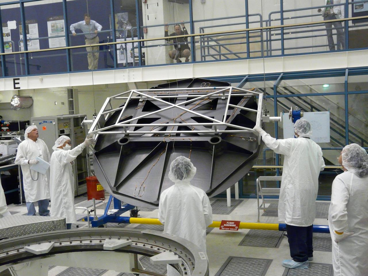
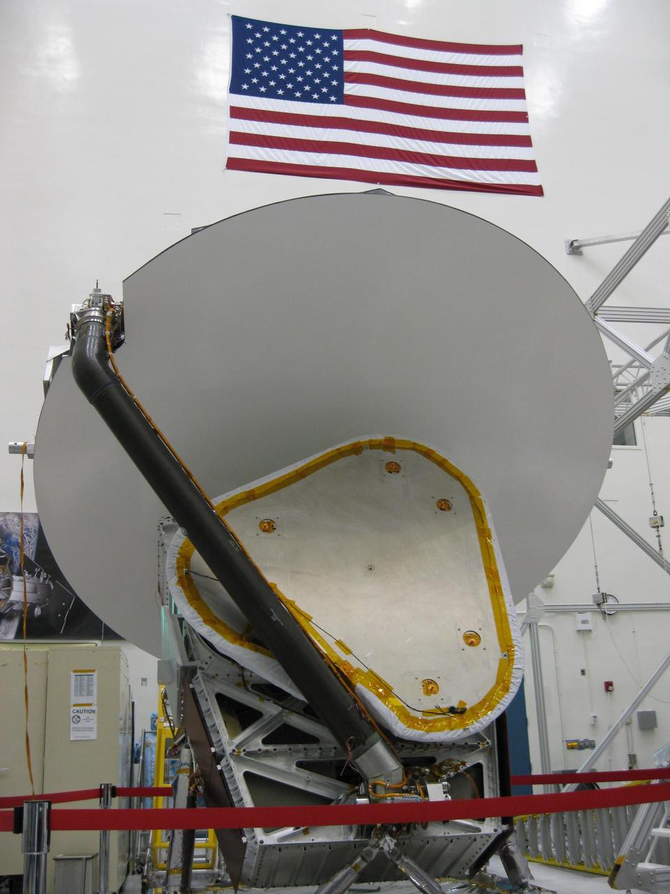
Engineers test Aquarius 2.5 meter reflector in the clean room at NASA Jet Propulsion Laboratory in Pasadena, Calif.
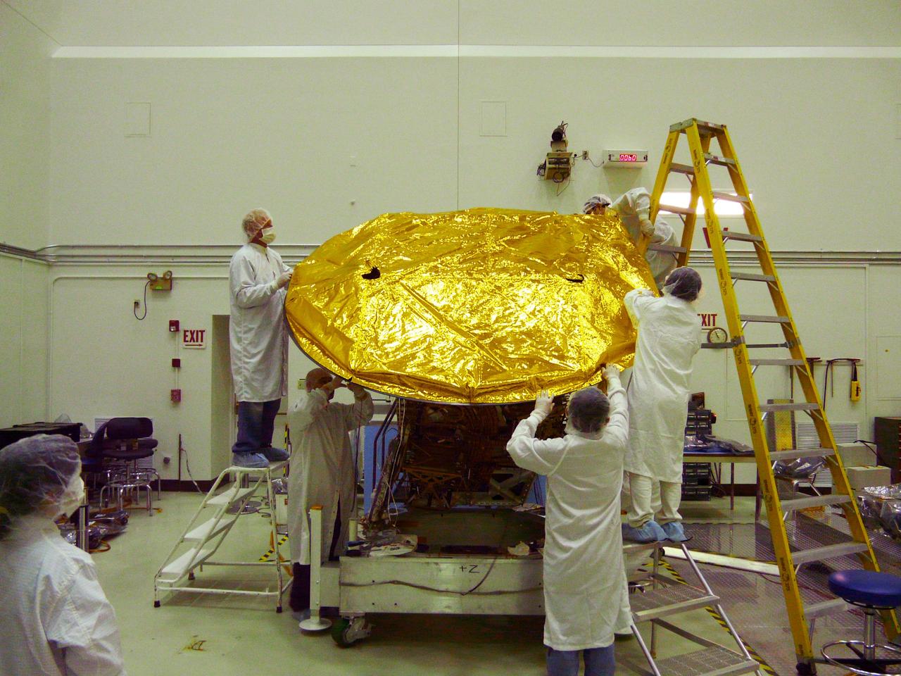
Aquarius 2.5 meter composite reflector being fitted with gold foil covering in the clean room at NASA Jet Propulsion Laboratory in Pasadena, Calif.
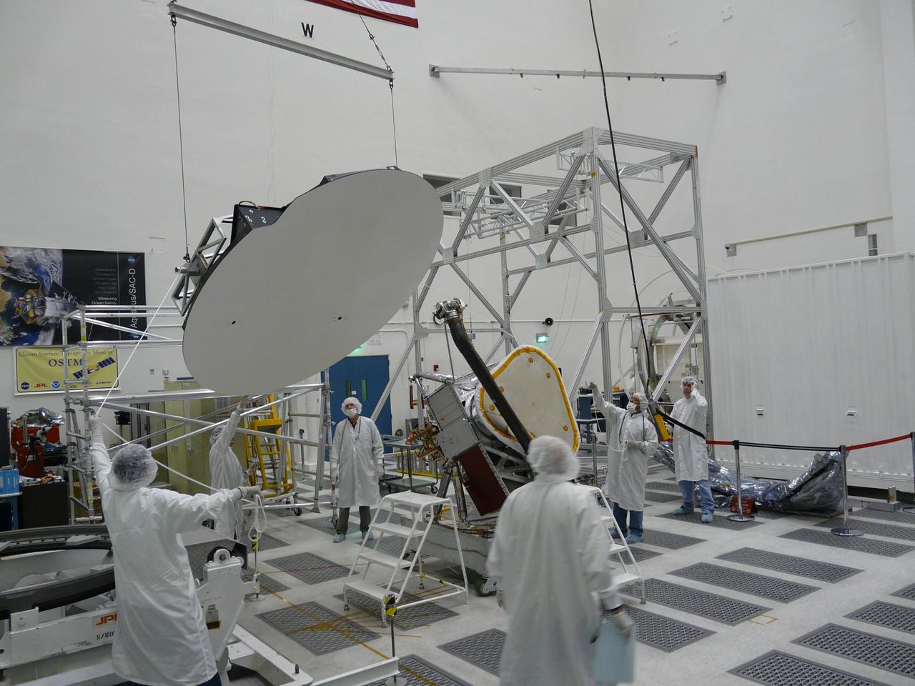
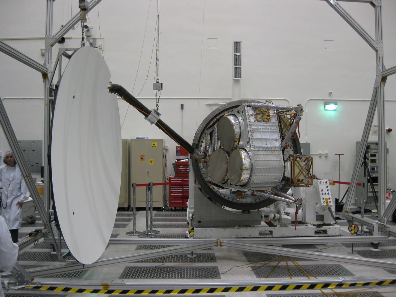
Aquarius 2.5 meter reflector is hoisted before being attached to boom in the clean room at NASA Jet Propulsion Laboratory in Pasadena, Calif.
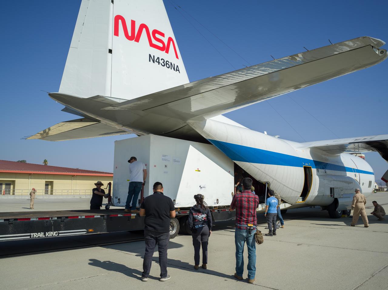
Crews at March Air Reserve Base in Riverside County, California, on Oct. 15, 2024, load a specialized shipping container carrying the NISAR (NASA ISRO Synthetic Aperture Radar) mission's radar antenna reflector into the hold of NASA's C-130 Hercules plane. The aircraft later departed on a multistage journey to Bengaluru, India, arriving on Oct. 22. A key piece of science hardware for the mission, which is a joint effort of NASA and the Indian Space Research Organisation, the reflector had been undergoing work at a specialized facility in California. Engineers there applied reflective tape and took other precautionary measures to mitigate temperature increases that could potentially have affected the deployment of the reflector from its stowed configuration. Drum-shaped and about 39 feet (12 meters) across, the reflector is among NASA's contributions to the mission. The reflector is designed to transmit and receive microwave signals to and from Earth's surface, enabling NISAR to scan nearly all the planet's land and ice surfaces twice every 12 days to collect science data. Once NISAR is in operation, its observations will benefit humanity by helping researchers around the world better understand changes in the planet's surface, including its ice sheets, glaciers, and sea ice. The spacecraft will also capture changes in forest and wetland ecosystems as well as movement and deformation of our planet's crust. https://photojournal.jpl.nasa.gov/catalog/PIA26419
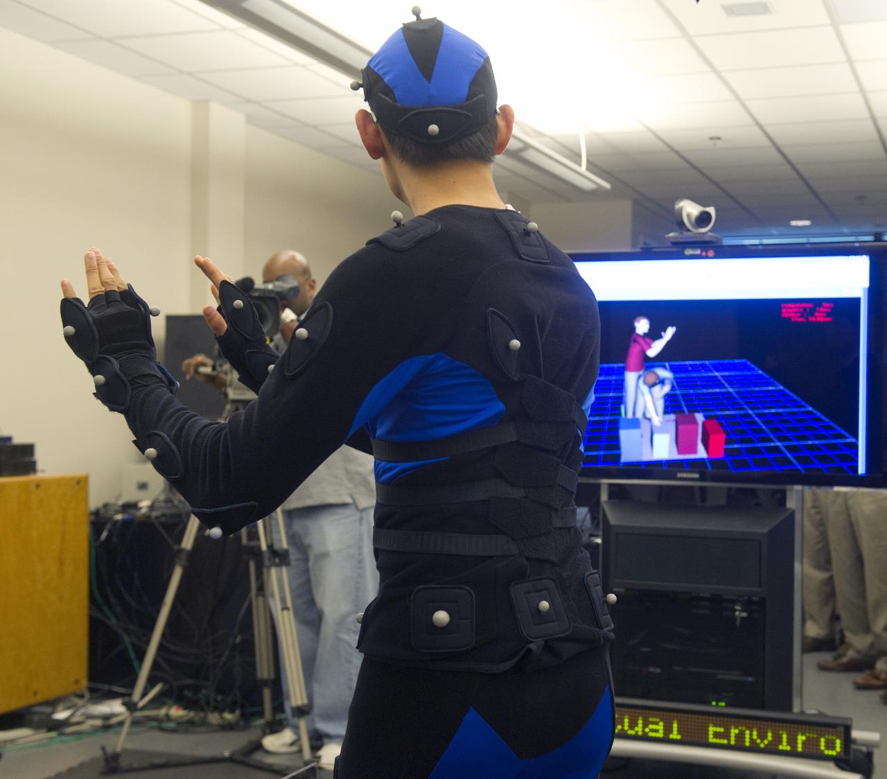
PETER MA, EV74, WEARS A SUIT COVERED WITH SPHERICAL REFLECTORS THAT ENABLE HIS MOTIONS TO BE TRACKED BY THE MOTION CAPTURE SYSTEM. THE HUMAN MODEL IN RED ON THE SCREEN IN THE BACKGROUND REPRESENTS THE SYSTEM-GENERATED IMAGE OF PETER'S POSITION.

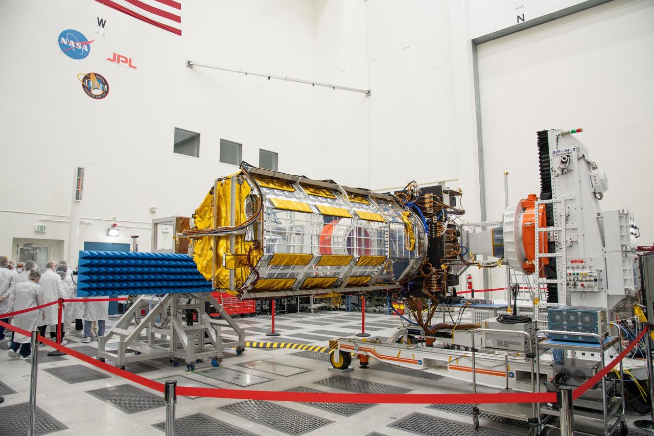
Members of the NISAR (NASA-ISRO Synthetic Aperture Radar) mission team at NASA's Jet Propulsion Laboratory in Southern California deployed the satellite's radar antenna reflector on Aug. 15, 2025. The JPL team, seen here in the lab's mission control, worked with a group at the Indian Space Research Organisation Telemetry, Tracking and Command Network in Bengaluru, India. Weighing about 142 pounds (64 kilograms) and measuring roughly 2 feet (0.6 meters) in diameter in its stowed configuration, the reflector unfurled to its full size, 39 feet (12 meters), over the course of 37 minutes. The deployment consisted of two stages – an initial "bloom" powered by the release of tension stored in the reflector's flexible frame while it was stowed. Subsequent activation of motors and cables then pulled the antenna into its final, operational position, where it was locked in place. The drum-shaped reflector is an essential component that enables the mission to collect data tracking change to Earth's land and ice surfaces. Observations from NISAR will benefit humanity by helping researchers around the world better understand changes in our planet's surface, including its ice sheets, glaciers, and sea ice. It also will capture changes in forest and wetland ecosystems and track movement and deformation of Earth's crust by phenomena such as earthquakes, landslides, and volcanic activity. The global and rapid coverage from NISAR will provide unprecedented support for disaster response, producing data to assist in mitigating and assessing damage, with observations before and after catastrophic events available in short time frames. The mission is an equal collaboration between NASA and the Indian Space Research Organisation and marks the first time the two agencies have cooperated on hardware development for an Earth-observing mission. NISAR launched from ISRO's Satish Dhawan Space Centre on India's southeastern coast on July 30, 2025. https://photojournal.jpl.nasa.gov/catalog/PIA26612

William J. O Sullivan at desk with folded subsatellite, 30 inch subsatellite, 12 foot subsatellite, and corner reflector.

William J. O Sullivan at desk with folded subsatellite, 30 inch subsatellite, 12 foot subsatellite, and corner reflector.
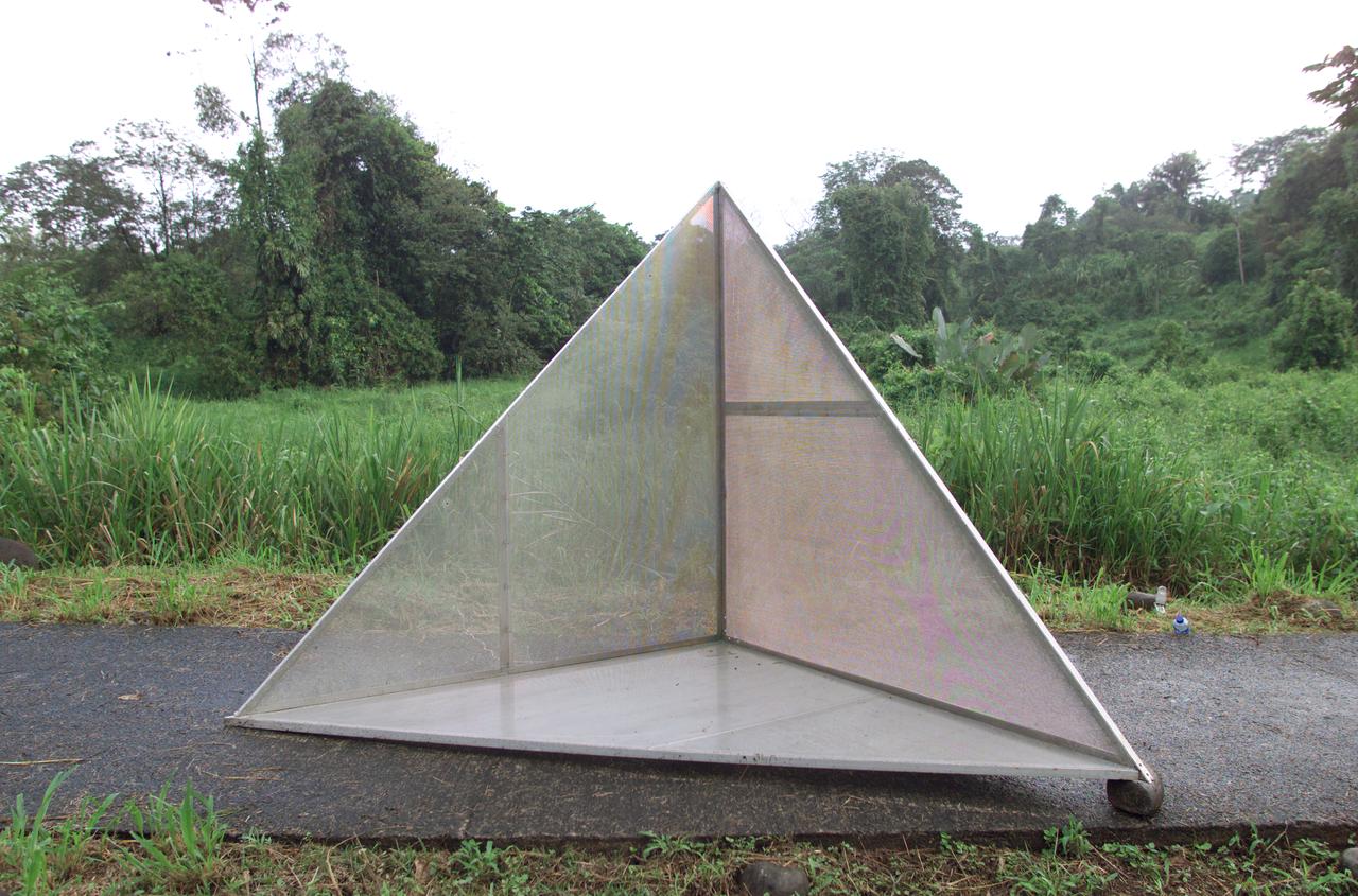
Reflectors setup in the La Selva region of the Costa Rican rain forest by scientist Paul Siqueira from NASA’s Jet Propulsion Lab. These reflectors are used by JPL scientists onboard Dryden's DC-8 aircraft to calibrate the Airborne Synthetic Aperture Radar (AirSAR) system. Scientists place these reflectors at known points on the ground, allowing researchers onboard the aircraft to verify their data. AirSAR 2004 Mesoamerica is a three-week expedition by an international team of scientists that uses an all-weather imaging tool, called the Airborne Synthetic Aperture Radar (AirSAR) which is located onboard NASA's DC-8 airborne laboratory. Scientists from many parts of the world including NASA's Jet Propulsion Laboratory are combining ground research done in several areas in Central America with NASA's AirSAR technology to improve and expand on the quality of research they are able to conduct. The radar, developed by NASA's Jet Propulsion Laboratory, can penetrate clouds and also collect data at night. Its high-resolution sensors operate at multiple wavelengths and modes, allowing AirSAR to see beneath treetops, through thin sand, and dry snow pack. AirSAR's 2004 campaign is a collaboration of many U.S. and Central American institutions and scientists, including NASA; the National Science Foundation; the Smithsonian Institution; National Geographic; Conservation International; the Organization of Tropical Studies; the Central American Commission for Environment and Development; and the Inter-American Development Bank.
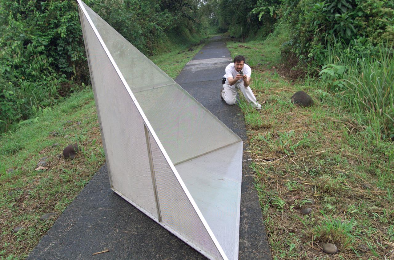
Reflectors setup in the La Selva region of the Costa Rican rain forest by scientist Paul Siqueira from NASA’s Jet Propulsion Lab. These reflectors are used by JPL scientists onboard Dryden's DC-8 aircraft to calibrate the Airborne Synthetic Aperture Radar (AirSAR) system. Scientists place these reflectors at known points on the ground, allowing researchers onboard the aircraft to verify their data. AirSAR 2004 Mesoamerica is a three-week expedition by an international team of scientists that uses an all-weather imaging tool, called the Airborne Synthetic Aperture Radar (AirSAR) which is located onboard NASA's DC-8 airborne laboratory. Scientists from many parts of the world including NASA's Jet Propulsion Laboratory are combining ground research done in several areas in Central America with NASA's AirSAR technology to improve and expand on the quality of research they are able to conduct. The radar, developed by NASA's Jet Propulsion Laboratory, can penetrate clouds and also collect data at night. Its high-resolution sensors operate at multiple wavelengths and modes, allowing AirSAR to see beneath treetops, through thin sand, and dry snow pack. AirSAR's 2004 campaign is a collaboration of many U.S. and Central American institutions and scientists, including NASA; the National Science Foundation; the Smithsonian Institution; National Geographic; Conservation International; the Organization of Tropical Studies; the Central American Commission for Environment and Development; and the Inter-American Development Bank.
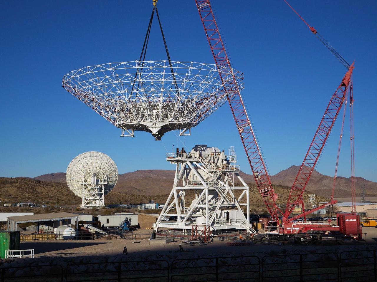
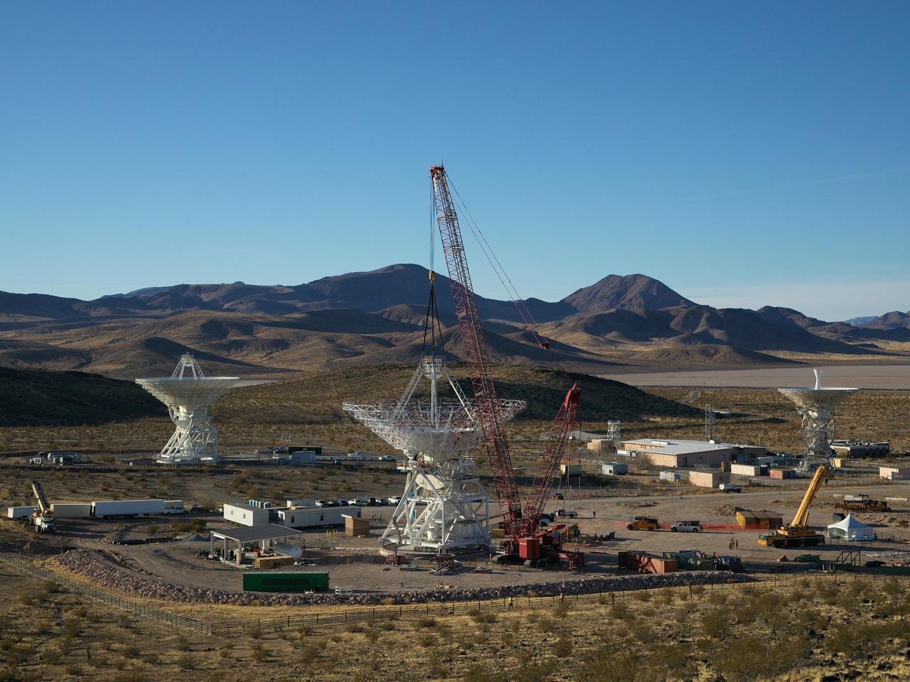
A crane lowers the 112-foot-wide (34-meter-wide) steel framework for the Deep Space Station 23 (DSS-23) reflector dish into position on Dec. 18, 2024, at the Deep Space Network's Goldstone Space Communications Complex near Barstow, California. A multi-frequency beam waveguide antenna, DSS-23 will boost the DSN's capacity and enhance NASA's deep space communications capabilities for decades to come. Once online in 2026, DSS-23 will be the fifth of six new beam waveguide antennas to be added to the network, following DSS-53, which was added at the DSN's Madrid complex in 2022. After the reflector skeleton was bolted into place, engineers placed what's called a quadripod into the center of the structure. A four-legged support structure weighing 16 ½ tons, the quadripod is fitted with a curved subreflector that will direct radio frequency signals from deep space that bounce off the main reflector into the antenna's pedestal where the antenna's receivers are housed. Next steps: to fit panels onto the steel skeleton of the parabolic reflector to create a curved surface to collect radio frequency signals. The DSN allows missions to track, send commands to, and receive scientific data from faraway spacecraft. It is managed by NASA's Jet Propulsion Laboratory in Southern California for the agency's Space Communications and Navigation (SCaN) program, which is located at NASA Headquarters within the Space Operations Mission Directorate. https://photojournal.jpl.nasa.gov/catalog/PIA26454
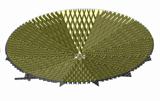
Aquarius reflector deployment is tested in the clean room at NASA Jet Propulsion Laboratory in Pasadena, Calif.
Aquarius instrument, including 2.5 meter reflector, in the clean room at NASA Jet Propulsion Laboratory in Pasadena, Calif.
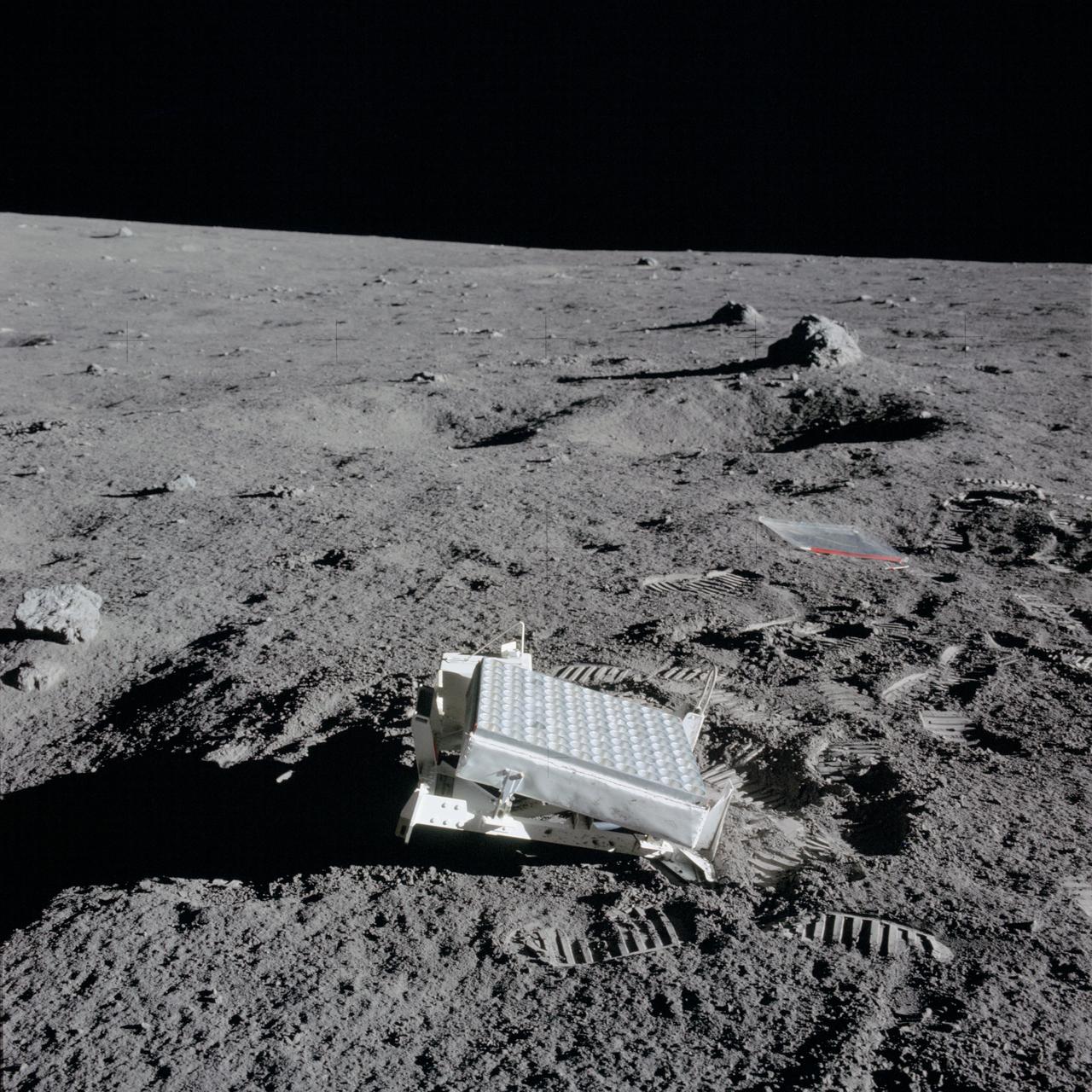
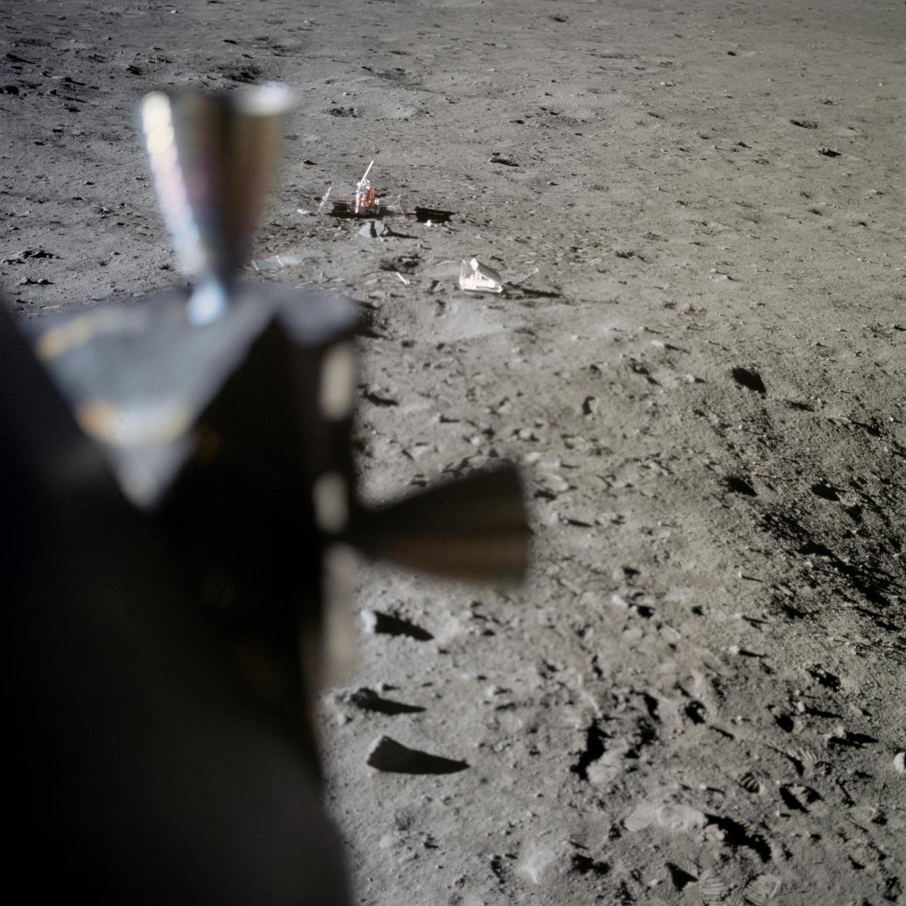
AS14-67-9386 (5 Feb. 1971) --- A close-up view of the laser ranging retro reflector (LR3) which the Apollo 14 astronauts deployed on the moon during their lunar surface extravehicular activity (EVA). While astronauts Alan B. Shepard Jr., commander, and Edgar D. Mitchell, lunar module pilot, descended in the Lunar Module (LM) to explore the moon, astronaut Stuart A. Roosa, command module pilot, remained with the Command and Service Modules (CSM) in lunar orbit.
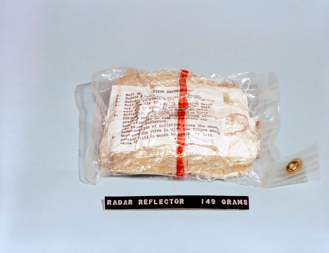
S62-06767 (1962) --- A radar reflector, survival equipment for the Mercury astronauts. Photo credit: NASA
A crane lowers a four-legged support structure called a quadripod onto the steel framework of the Deep Space Station 23 (DSS-23) reflector dish on Dec. 18, 2024. The reflector framework was bolted into place earlier in the day, and the quadripod, which weighs 16 ½ tons, was the last major component to be installed that day. The reflector dish will be fitted with panels to create a curved surface to collect radio frequency signals. The quadripod features a curved subreflector that will direct radio frequency signals from deep space that bounce off the main reflector into the antenna's receiver in its pedestal, where the antenna's receivers are housed. The new 112-foot-wide (34-meter-wide) dish is located at the Deep Space Network's Goldstone Space Communications Complex near Barstow, California. A multi-frequency beam waveguide antenna, DSS-23 will come online in 2026, boosting the DSN's capacity and enhance NASA's deep space communications capabilities for decades to come. It is the fifth of six new beam waveguide antennas to be added to the network, following DSS-53, which was added at the DSN's Madrid complex in 2022. The DSN allows missions to track, send commands to, and receive scientific data from faraway spacecraft. It is managed by NASA's Jet Propulsion Laboratory in Southern California for the agency's Space Communications and Navigation (SCaN) program, which is located at NASA Headquarters within the Space Operations Mission Directorate. https://photojournal.jpl.nasa.gov/catalog/PIA26455
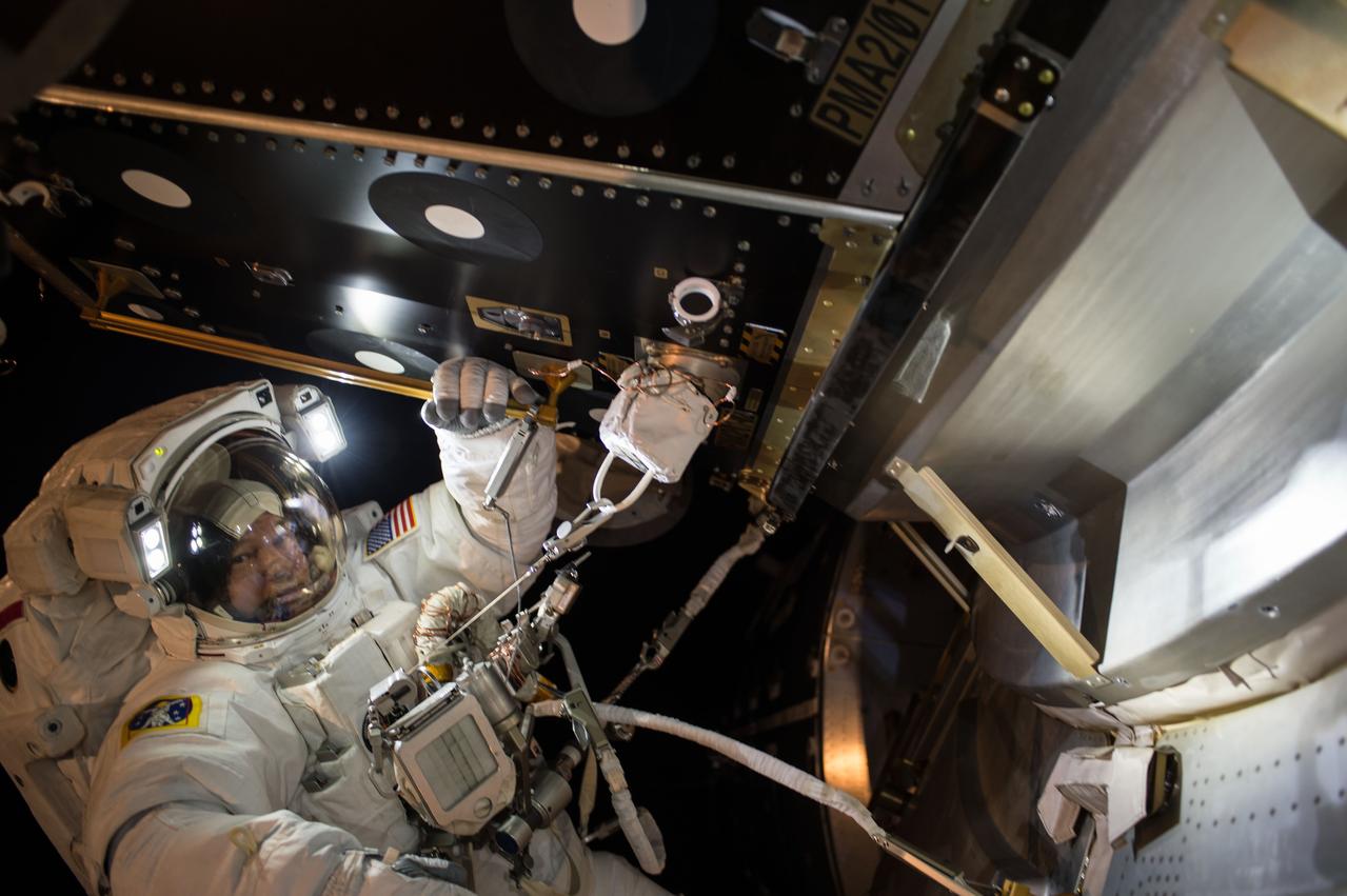
Extravehicular crewmember 1 (EV1) Jeff Williams pauses for a photo after installing a Hemispherical (Hemi) Reflector Cover on Pressurized Mating Adapter 2 (PMA-2) during Extravehicular Activity 36 (EVA 36).
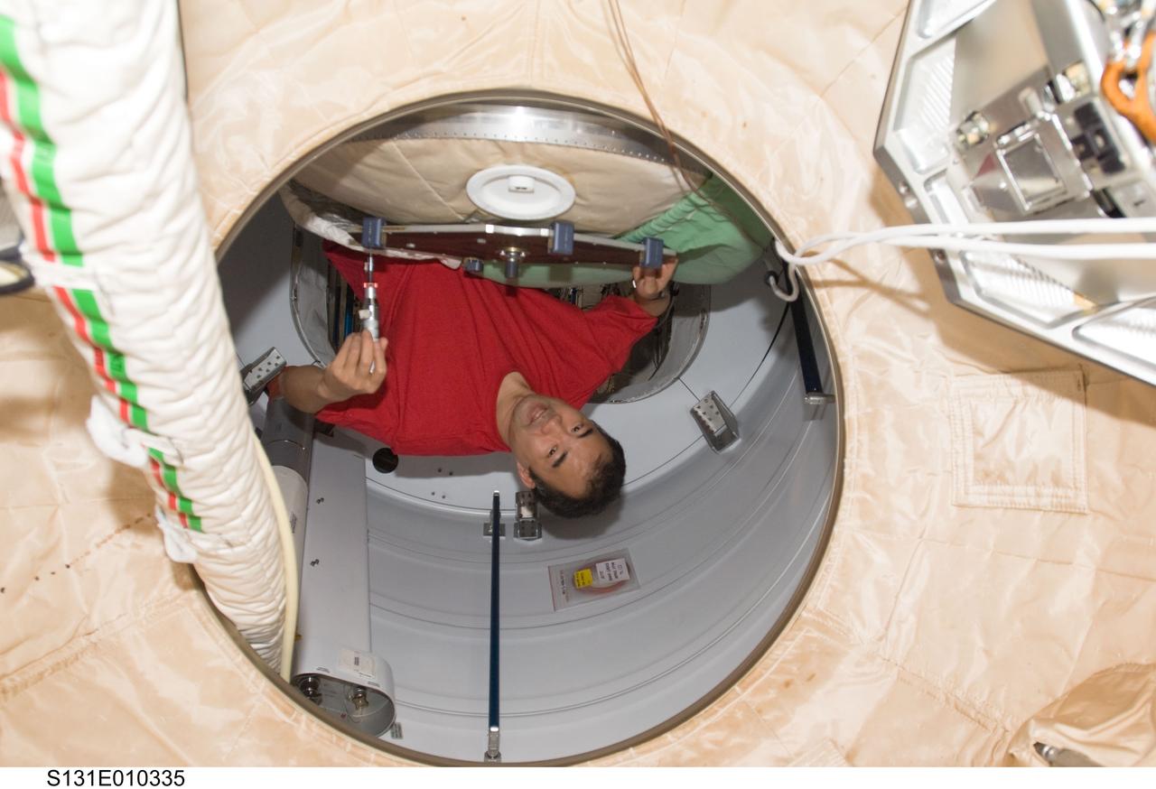
S131-E-010335 (16 April 2010) --- Japan Aerospace Exploration Agency (JAXA) astronaut Soichi Noguchi, Expedition 23 flight engineer, works to relocate a reflective element on the PMA-2 docking target in support of the Sensor Test for Orion Relative Navigation Risk Mitigation (STORRM) on the International Space Station while space shuttle Discovery (STS-131) remains docked with the station.
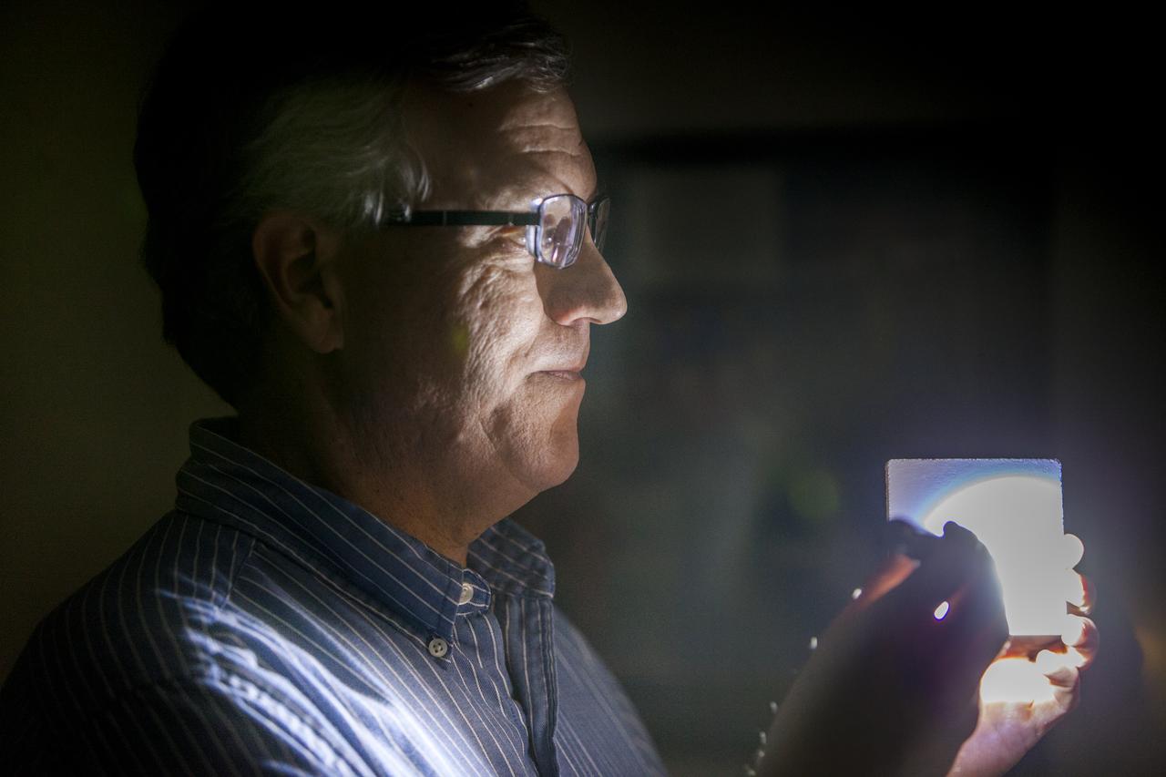
Robert Youngquist, Ph.D., tests a sample disk with a "Solar White" cryogenic selective surface coating with a flash light, demonstrating the coating’s reflective properties. The innovative coating is predicted to reflect more than 99.9 percent of the simulated solar infrared radiation. This technology could enable storing super-cold, or cryogenic, liquids and support systems that shield astronauts against radiation during the Journey to Mars.
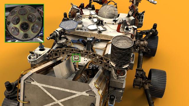
Visible near the center of NASA's Perseverance Mars rover in this illustration is the palm-size dome called the Laser Retroreflector Array (LaRA). In the distant future, laser-equipped Mars orbiters could use such a reflector for scientific studies. https://photojournal.jpl.nasa.gov/catalog/PIA24097
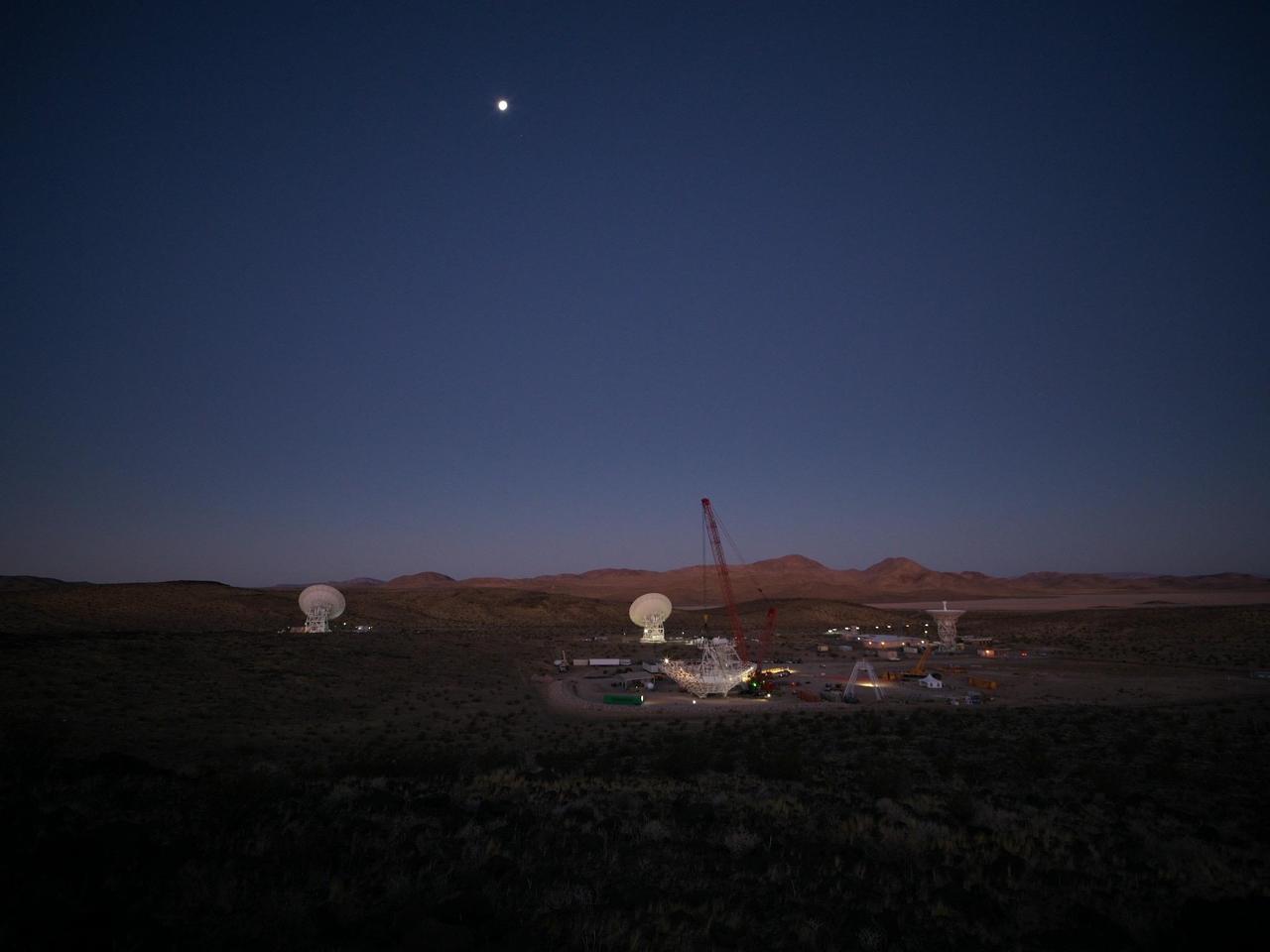
In the early morning of Dec. 18, 2024, a crane looms over the 112-foot-wide (34-meter-wide) steel framework for Deep Space Station 23 (DSS-23) reflector dish, which will soon be lowered into position on the antenna's base structure. Located at the Deep Space Network's Goldstone Space Communications Complex near Barstow, California, DSS-23 is a multi-frequency beam waveguide antenna that will boost the DSN's capacity and enhance NASA's deep space communications capabilities for decades to come. In the background are, from left to right, the beam waveguide antennas DSS-25 and DSS-26, and the decommissioned 85-foot (26-meter) Apollo antenna. https://photojournal.jpl.nasa.gov/catalog/PIA26456
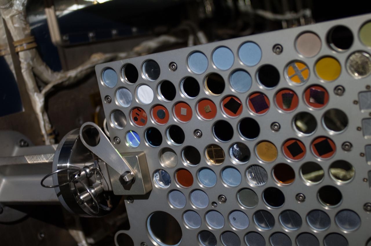
iss036e016736 (7/9/2013) --- Close-up view of the Optical Reflector Materials Experiment III Ram/Wake (ORMatE-III R/W) which is part of the Materials on International Space Station Experiment - 8 (MISSE-8) installed on the starboard truss. View was taken during a session of extravehicular activity (EVA) 22 as work continues on the International Space Station.
AS11-37-5551 (20 July 1969) --- Two components of the Early Apollo Scientific Experiments Package (EASEP) are seen deployed on the lunar surface in this view photographed from inside the Lunar Module (LM). In the far background is the Passive Seismic Experiment Package (PSEP); and to the right and closer to the camera is the Laser Ranging Retro-Reflector (LR-3). The footprints of Apollo 11 astronauts Neil A. Armstrong and Edwin E. Aldrin Jr. are very distinct in the lunar soil.
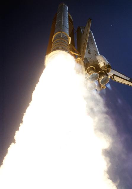
The Space Shuttle Columbia (STS-52) thunders off Launch Pad 39B, embarking on a 10-day flight and carrying a crew of six who will deploy the Laser Geodynamic Satellite II (LAGEOS). LAGEOS is a spherical passive satellite covered with reflectors which are illuminated by ground-based lasers to determine precise measurements of the Earth's crustal movements. The other major payload on this mission is the United States Microgravity Payload 1 (USMP-1), where experiments will be conducted by crew members while in low earth orbit (LEO).

iss072e488176 (Jan. 16, 2025) --- NASA astronaut and Expedition 72 Commander Suni Williams (center) is dwarfed near the SpaceX Dragon crew spacecraft as she replaces a planar reflector, advanced navigational hardware visiting vehicles use when approaching the International Space Station. Dragon is docked to the Harmony module's space-facing port which rests in between the Kibo and Columbus laboratory modules. 263 miles below is the Atlantic Ocean near the coast of Brazil.

The Space Shuttle Columbia (STS-52) thunders off Launch Pad 39B, embarking on a 10-day flight and carrying a crew of six who will deploy the Laser Geodynamic Satellite II (LAGEOS). LAGEOS is a spherical passive satellite covered with reflectors which are illuminated by ground-based lasers to determine precise measurements of the Earth's crustal movements. The other major payload on this mission is the United States Microgravity Payload 1 (USMP-1), where experiments will be conducted by crew members while in low earth orbit (LEO).

S71-16101 (January 1971) --- A Grumman Aerospace Corporation artist's concept of Apollo 14 crewmen, astronauts Alan B. Shepard Jr., commander, and Edgar D. Mitchell, lunar module pilot, as they set out on their first traverse. Shepard is pulling the Modularized Equipment Transporter (MET) which contains cameras, lunar sample bags, tools and other paraphernalia. Shepard has the Laser Ranging Retro-Reflector (LR-3) in his other hand. Mitchell is carrying the Apollo Lunar Surface Experiments Package (ALSEP) barbell mode.
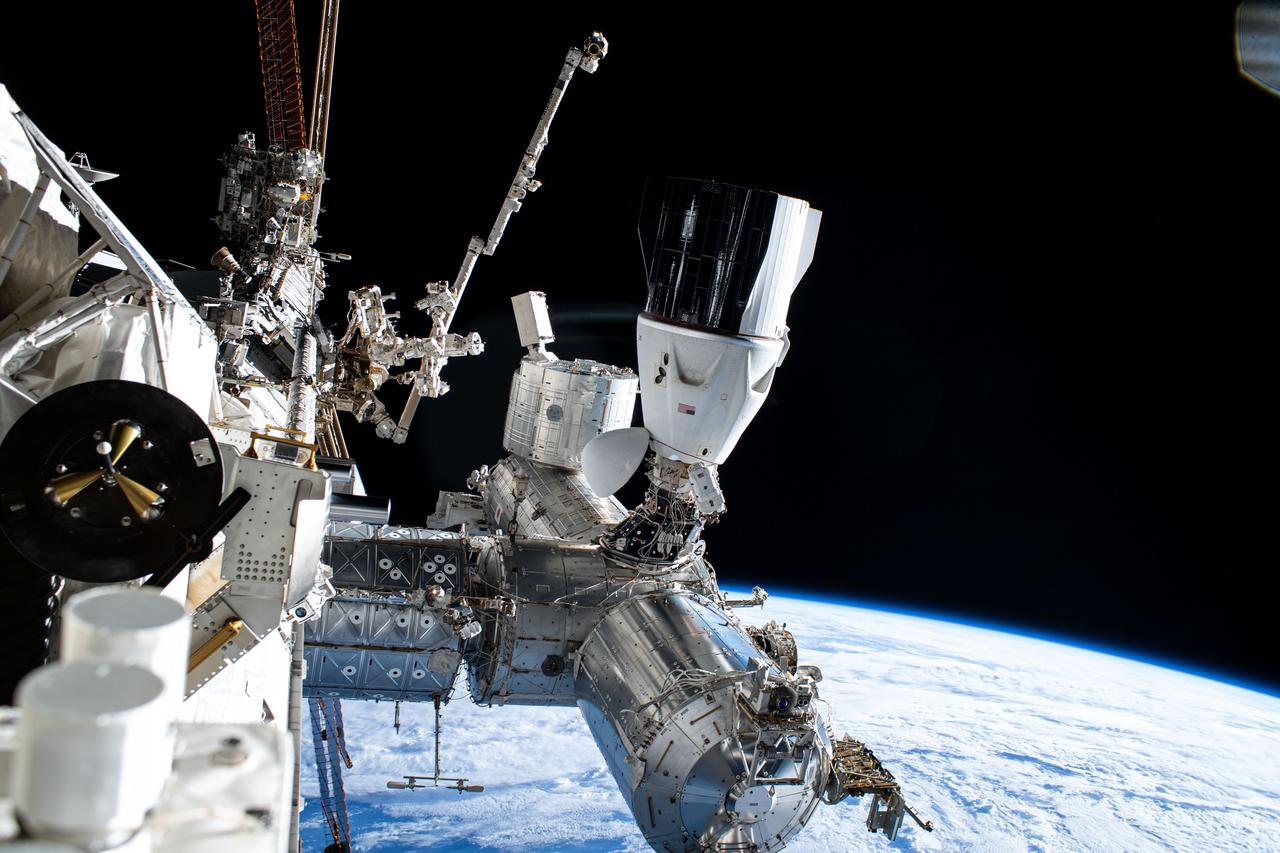
iss072e488017 (Jan. 16, 2025) --- NASA astronaut and Expedition 72 Commander Suni Williams (center) is dwarfed near the SpaceX Dragon crew spacecraft as she replaces a planar reflector, advanced navigational hardware visiting vehicles use when approaching the International Space Station. Dragon is docked to the Harmony module's space-facing port which rests in between the Kibo and Columbus laboratory modules. 267 miles below is the Pacific Ocean east of New Zealand.

ISS042E292519 (03/01/2015) --- U.S. astronaut Terry Virts tweeted his followers this image after completing a series of spacewalks with his partner astronaut Barry "Butch" Wilmore to prepare the International Space Station for upcoming U.S. commercial spacecraft currently in development. Virts commented on the tweet: "Mission Accomplished - 3 #spacewalks, 800' of cable, 4 antennas, 3 laser reflectors, 1 greased robotic arm."

Launching of the LJ6 Little Joe on Oct. 4, 1959 took place at Wallops Island, Va. This was the first attempt to launch an instrumented capsule with a Little Joe booster. Only the LJ1A and the LJ6 used the space metal chevron plates as heat reflector shields, as they kept shattering. Caption title ...and ascending skyward on a plume of exhaust. Photograph published in Winds of Change, 75th Anniversary NASA publication, page 77, by James Schultz
The Space Shuttle Columbia (STS-52) thunders off Launch Pad 39B, embarking on a 10-day flight and carrying a crew of six who will deploy the Laser Geodynamic Satellite II (LAGEOS). LAGEOS is a spherical passive satellite covered with reflectors which are illuminated by ground-based lasers to determine precise measurements of the Earth's crustal movements. The other major payload on this mission is the United States Microgravity Payload 1 (USMP-1), where experiments will be conducted by crew members while in low earth orbit (LEO).
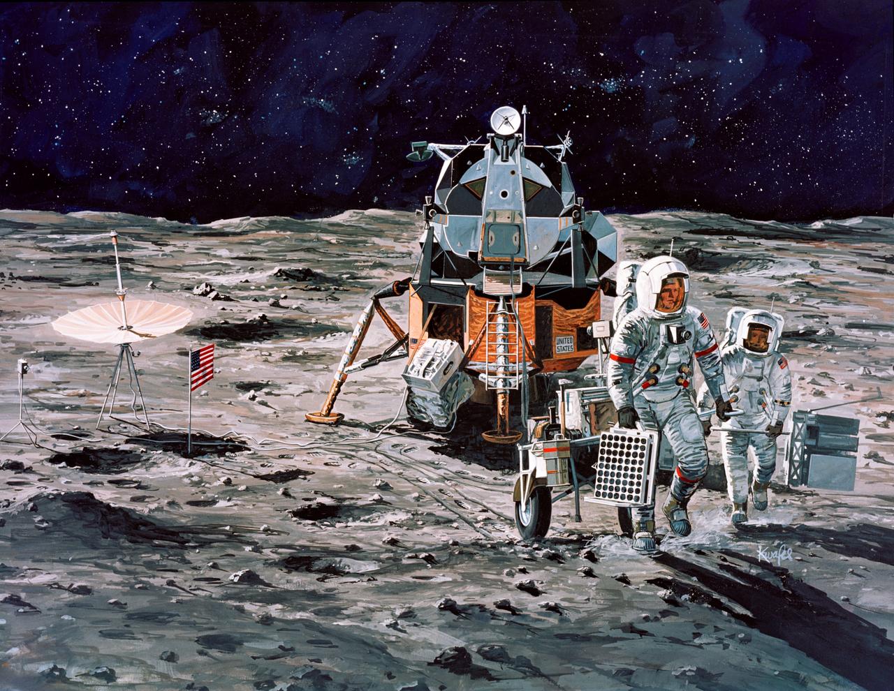
S71-16102 (January 1971) --- A Grumman Aerospace Corporation artist's concept of Apollo 14 crewmen, astronauts Alan B. Shepard Jr., commander, and Edgar D. Mitchell, lunar module pilot, as they set out on their first traverse. Shepard is pulling the Modularized Equipment Transporter (MET) which contains cameras, lunar sample bags, tools and other paraphernalia. Shepard has the Laser Ranging Retro-Reflector (LR3) in his other hand. Mitchell is carrying the Apollo Lunar Surface Experiments Package (ALSEP) barbell mode.
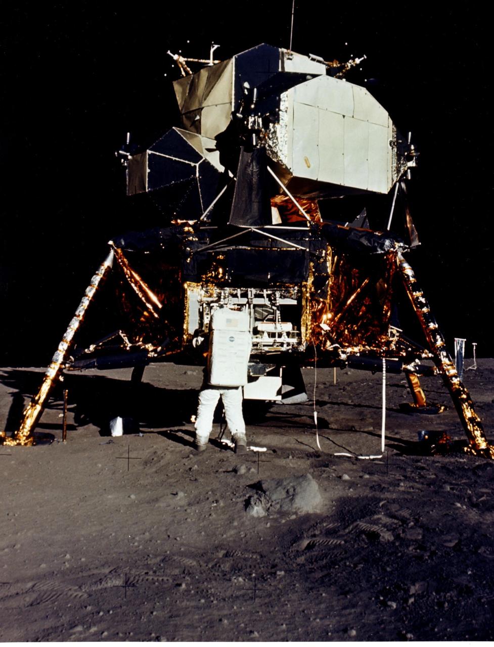
JOHNSON SPACE CENTER, HOUSTON, TEXAS - Man's first landing on the Moon was accomplished at 4:17 p.m. today as Lunar Module "Eagle" touched down gently on the Sea of Tranquility on the east side of the Moon. Astronaut Edwin E. Aldrin Jr., Lunar Module Pilot, removes scientific experiment packages from a stowage area in the Lunar Module's descent stage. Left behind on the lunar surface by Aldrin and Neil A. Armstrong, Apollo 11 commander, were a Passive Seismic Experiments Package and a Laser-Ranging Retro-Reflector.
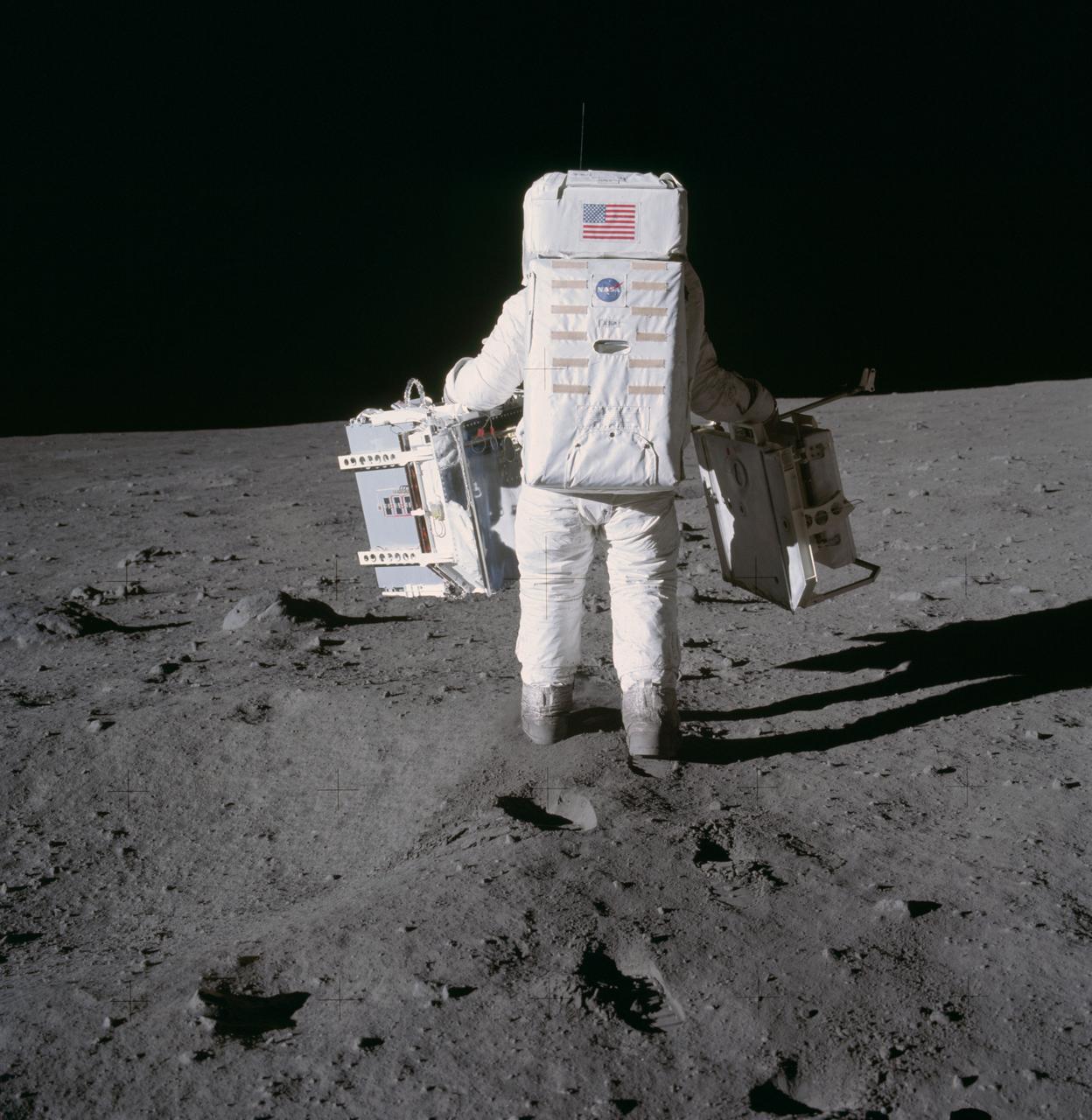
Astronaut Edwin E. Aldrin Jr., lunar module pilot, moves toward a position to deploy two components of the Early Apollo Scientific Experiments Package (EASEP) on the surface of the Moon during the Apollo 11 extravehicular activity. The Passive Seismic Experiments Package (PSEP) is in his left hand; and in his right hand is the Laser Ranging Retro-Reflector (LR3). Astronaut Neil A. Armstrong, commander, took this photograph with a 70mm lunar surface camera.
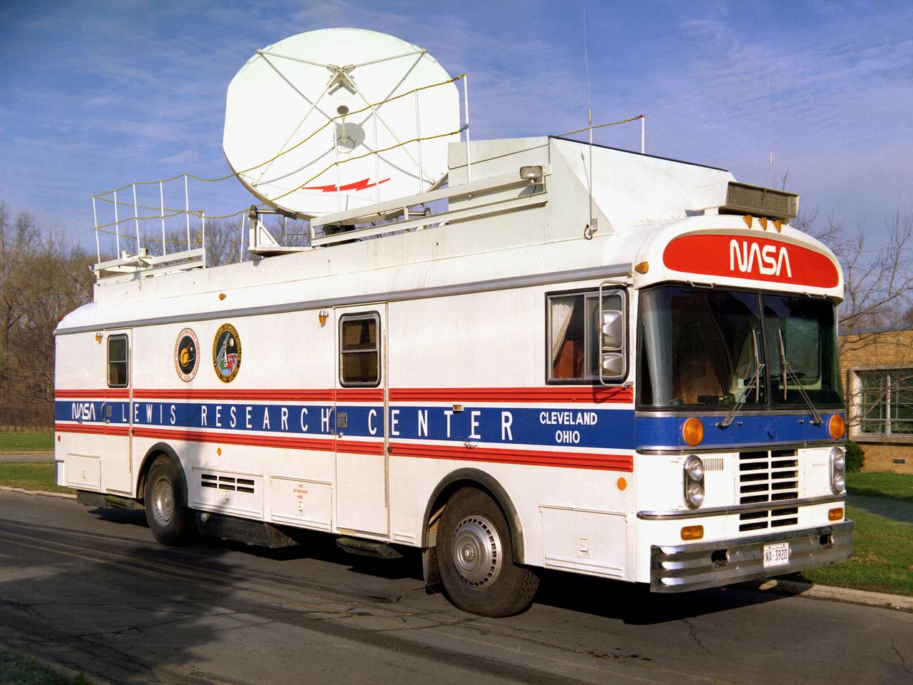
This vehicle served as a mobile terminal for the Communications Technology Satellite. The Communications Technology Satellite was an experimental communications satellite launched in January 1976 by the National Aeronautics and Space Administration (NASA) and the Canadian Department of Communications. The satellite operated in a new frequency band reserved for broadcast satellites with transmitting power levels that were 10 to 20 times higher than those of contemporary satellites. Throughout 1977 and 1978 NASA allowed qualified groups to utilize the satellite from one of the three ground-based transmission centers. NASA’s Lewis Research Center in Cleveland, Ohio was NASA’s lead center on the project. Lewis was responsible for the control and coordination of all US experiments on the satellite. The center housed the satellite’s main control center which included eight parabolic reflector antennae ranging from 2 to 15 feet in diameter. Many of the satellite’s components had been tested in simulated space conditions at Lewis. The Lewis-designed vehicle seen here served as a field unit for transmitting and receiving wideband signals and narrowband voice. The vehicle permitted live television interviews, recording equipment, and cameras. An 8-foot diameter parabolic reflector was mounted on the roof. The interior of the vehicle had workstations, monitors, transmitting equipment, and a lounge area.
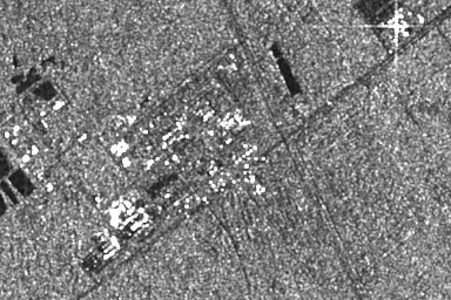
This image was produced during radar observations taken by the Spaceborne Imaging Radar-C/X-band Synthetic Aperture Radar as it flew over the Gulf Stream, Florida, and past the Atlantic Ocean on October 7, 1994. The data were produced using the X-band radar frequency. Knowing ahead of time that this region would be included in a regularly scheduled radar pass, the Kennedy Space Center team, who assembled and integrated the SIR-C/X-SAR equipment with the Spacelab pallet system, designed a set of radar reflectors from common construction materials and formed the letters "KSC" on the ground adjacent to the main headquarters building at the entrance to the Cape Canaveral launch facility. The point of light formed by the bright return from these reflectors are visible in the image. Other more diffuse bright spots are reflections from building faces, roofs and other large structures at the Kennedy Space Center complex. This frame covers an area of approximately 6 kilometers by 8 kilometers (4 miles by 5 miles), which was just a small portion of the data taken on this particular pass. http://photojournal.jpl.nasa.gov/catalog/PIA01747
Aligned straight on with the red approach lights, the Orbiter Columbia (STS-52) glides toward Runway 33 of Kennedy Space Center's (KSC) Shuttle Landing Facility. The six member crew successfully completed deployment of the Laser Geodynamic Satellite II (LAGEOS), which is a spherical passive satellite covered with reflectors which are illuminated by ground-based lasers to determine precise measurements of the Earth's crustal movements. The crew also completed a series of materials processing experiments in the microgravity environment aboard the United States Microgravity Payload 1 (USMP-1) carried in the orbiter's cargo bay.
jsc2020e040943 (9/10/2020) --- An example of a copper zirconium antenna metal mesh on a deployable reflector. The Exposure Experiment of Copper-Zirconium Antenna Metal Mesh to the Space Environment (ExHAM-Antenna Metal Mesh) investigation tests how well an antenna metal mesh, made from copper and zirconium, performs in the space environment in low-Earth orbit (LEO). While in space, the antenna metal mesh is exposed to cosmic rays and atomic oxygen in the LEO space environment - which can degrade antenna performance. Image Credit: Technosolver Corporation, JAXA.
AS14-66-9277 (5 Feb. 1971) --- An excellent view of the Apollo 14 Lunar Module (LM) on the moon, as photographed during the first Apollo 14 extravehicular activity (EVA) on the lunar surface. The astronauts have already deployed the U.S. flag. Note the laser ranging retro reflector (LR-3) at the foot of the LM ladder. The LR-3 was deployed later. While astronauts Alan B. Shepard Jr., commander, and Edgar D. Mitchell, lunar module pilot, descended in the LM to explore the moon, astronaut Stuart A. Roosa, command module pilot, remained with the Command and Service Modules (CSM) in lunar orbit.
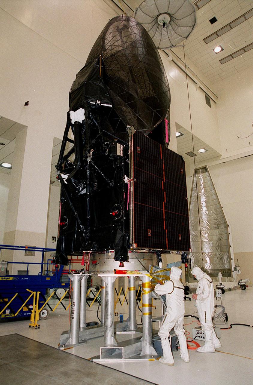
The Tracking and Data Relay Satellite (TDRS-H) sits on a workstand in KSC’s Spacecraft Assembly and Encapsulation Facility (SAEF-2) in order to undergo electrical testing. The TDRS is scheduled to be launched from CCAFS June 29 aboard an Atlas IIA/Centaur rocket. One of three satellites (labeled H, I and J) being built in the Hughes Space and Communications Company Integrated Satellite Factory in El Segundo, Calif., the latest TDRS uses an innovative springback antenna design. A pair of 15-foot-diameter, flexible mesh antenna reflectors fold up for launch, then spring back into their original cupped circular shape on orbit. The new satellites will augment the TDRS system’s existing Sand Ku-band frequencies by adding Ka-band capability. TDRS will serve as the sole means of continuous, high-data-rate communication with the space shuttle, with the International Space Station upon its completion, and with dozens of unmanned scientific satellites in low earth orbit

Leaving billowing clouds of steam and smoke behind, NASA’s Tracking and Data Relay Satellite (TDRS-H) shoots into the blue sky aboard an Atlas IIA/Centaur rocket from Pad 36A, Cape Canaveral Air Force Station. Liftoff occurred at 8:56 a.m. EDT. One of three satellites (labeled H, I and J) being built by the Hughes Space and Communications Company, the latest TDRS uses an innovative springback antenna design. A pair of 15-foot-diameter, flexible mesh antenna reflectors fold up for launch, then spring back into their original cupped circular shape on orbit. The new satellites will augment the TDRS system’s existing Sand Ku-band frequencies by adding Ka-band capability. TDRS will serve as the sole means of continuous, high-data-rate communication with the space shuttle, with the International Space Station upon its completion, and with dozens of unmanned scientific satellites in low earth orbit
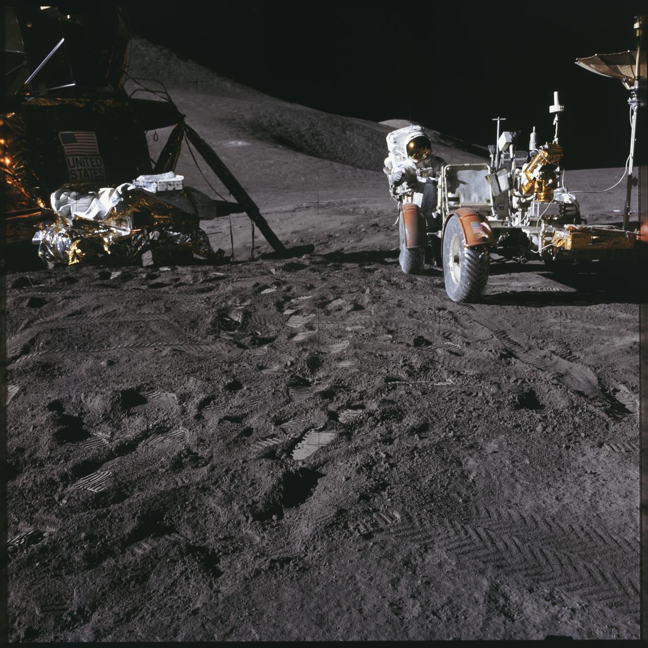
AS15-86-11601 (31 July 1971) --- Astronaut James B. Irwin, lunar module pilot, works at the Lunar Roving Vehicle (LRV) during the first Apollo 15 lunar surface extravehicular activity (EVA) at the Hadley-Apennine landing site. The Lunar Module (LM) "Falcon" is on the left. The undeployed Laser Ranging Retro Reflector (LR-3) lies atop the LM's modular equipment stowage assembly (MESA). This view is looking slightly west of south. Hadley Delta and the Apennine Front are in the background to the left. St. George crater is approximately five kilometers (about three statute miles) in the distance behind Irwin's head. This photograph was taken by astronaut David R. Scott, commander. While astronauts Scott and Irwin descended in the LM to explore the moon, astronaut Alfred M. Worden, command module pilot, remained with the Command and Service Modules (CSM) in lunar orbit.
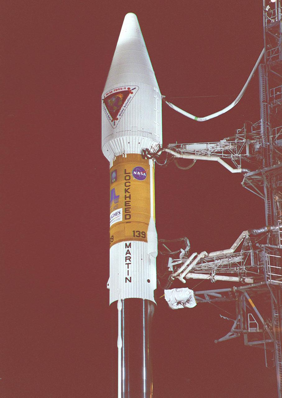
In the early morning hours on Launch Pad 36A, Cape Canaveral Air Force Station, the tower rolls back from NASA’s Tracking and Data Relay Satellite (TDRS-H) before liftoff atop an Atlas IIA/Centaur rocket. One of three satellites (labeled H, I and J) being built by the Hughes Space and Communications Company, the latest TDRS uses an innovative springback antenna design. A pair of 15-foot-diameter, flexible mesh antenna reflectors fold up for launch, then spring back into their original cupped circular shape on orbit. The new satellites will augment the TDRS system’s existing Sand Ku-band frequencies by adding Ka-band capability. TDRS will serve as the sole means of continuous, high-data-rate communication with the Space Shuttle, with the International Space Station upon its completion, and with dozens of unmanned scientific satellites in low earth orbit
Looking like a Roman candle, NASA’s Tracking and Data Relay Satellite (TDRS-H) shoots into the blue sky aboard an Atlas IIA/Centaur rocket from Pad 36A, Cape Canaveral Air Force Station. Liftoff occurred at 8:56 a.m. EDT. One of three satellites (labeled H, I and J) being built by the Hughes Space and Communications Company, the latest TDRS uses an innovative springback antenna design. A pair of 15-foot-diameter, flexible mesh antenna reflectors fold up for launch, then spring back into their original cupped circular shape on orbit. The new satellites will augment the TDRS system’s existing Sand Ku-band frequencies by adding Ka-band capability. TDRS will serve as the sole means of continuous, high-data-rate communication with the space shuttle, with the International Space Station upon its completion, and with dozens of unmanned scientific satellites in low earth orbit
In the early morning hours, NASA’s Tracking and Data Relay Satellite (TDRS-H) sits poised on Launch Pad 36A, Cape Canaveral Air Force Station, before its scheduled launch aboard an Atlas IIA/Centaur rocket. One of three satellites (labeled H, I and J) being built by the Hughes Space and Communications Company, the latest TDRS uses an innovative springback antenna design. A pair of 15-foot-diameter, flexible mesh antenna reflectors fold up for launch, then spring back into their original cupped circular shape on orbit. The new satellites will augment the TDRS system’s existing Sand Ku-band frequencies by adding Ka-band capability. TDRS will serve as the sole means of continuous, high-data-rate communication with the Space Shuttle, with the International Space Station upon its completion, and with dozens of unmanned scientific satellites in low earth orbit
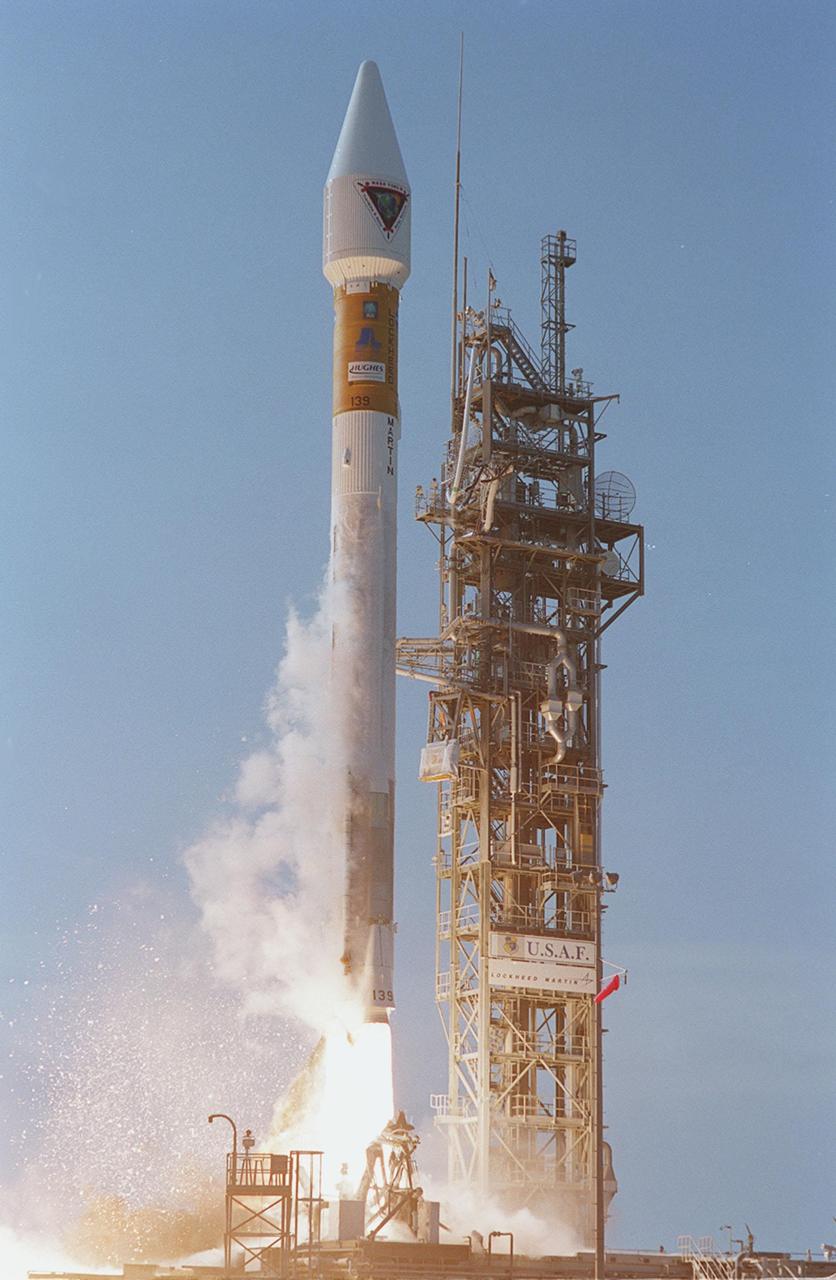
NASA’s Tracking and Data Relay Satellite (TDRS-H) rises into the blue sky from Pad 36A, Cape Canaveral Air Force Station. Liftoff occurred at 8:56 a.m. EDT aboard an Atlas IIA/Centaur rocket. One of three satellites (labeled H, I and J) being built by the Hughes Space and Communications Company, the latest TDRS uses an innovative springback antenna design. A pair of 15-foot-diameter, flexible mesh antenna reflectors fold up for launch, then spring back into their original cupped circular shape on orbit. The new satellites will augment the TDRS system’s existing Sand Ku-band frequencies by adding Ka-band capability. TDRS will serve as the sole means of continuous, high-data-rate communication with the space shuttle, with the International Space Station upon its completion, and with dozens of unmanned scientific satellites in low earth orbit

Workers in KSC’s Spacecraft Assembly and Encapsulation Facility (SAEF-2) prepare the Tracking and Data Relay Satellite (TDRS-H) above them for electrical testing. The TDRS is scheduled to be launched from CCAFS June 29 aboard an Atlas IIA/Centaur rocket. One of three satellites (labeled H, I and J) being built in the Hughes Space and Communications Company Integrated Satellite Factory in El Segundo, Calif., the latest TDRS uses an innovative springback antenna design. A pair of 15-foot-diameter, flexible mesh antenna reflectors fold up for launch, then spring back into their original cupped circular shape on orbit. The new satellites will augment the TDRS system’s existing Sand Ku-band frequencies by adding Ka-band capability. TDRS will serve as the sole means of continuous, high-data-rate communication with the space shuttle, with the International Space Station upon its completion, and with dozens of unmanned scientific satellites in low earth orbit
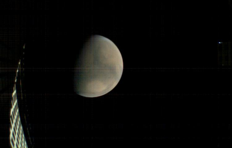
MarCO-B, one of the experimental Mars Cube One (MarCO) CubeSats, took this image of Mars from about 11,300 miles (18,200 kilometers) away shortly before NASA's InSight spacecraft landed on Mars on Nov. 26, 2018. MarCO-B flew by Mars with its twin, MarCO-A, to serve as communications relays for InSight spacecraft as it touched down around noon PST (3 p.m. EST). This image was taken at 10:35 a.m. PST (1:35 p.m. EST). Mars' north pole is at the top. A lighter-toned circular feature known as Hellas Basin is visible in the southern hemisphere. MarCO-B's antenna reflector can be seen at left. The blue dot on the right is a glint of sunlight off the antenna feed (not visible in the picture). https://photojournal.jpl.nasa.gov/catalog/PIA22831

In the early morning hours on Launch Pad 36A, Cape Canaveral Air Force Station, the tower rolls back from NASA’s Tracking and Data Relay Satellite (TDRS-H) before liftoff atop an Atlas IIA/Centaur rocket. One of three satellites (labeled H, I and J) being built by the Hughes Space and Communications Company, the latest TDRS uses an innovative springback antenna design. A pair of 15-foot-diameter, flexible mesh antenna reflectors fold up for launch, then spring back into their original cupped circular shape on orbit. The new satellites will augment the TDRS system’s existing Sand Ku-band frequencies by adding Ka-band capability. TDRS will serve as the sole means of continuous, high-data-rate communication with the Space Shuttle, with the International Space Station upon its completion, and with dozens of unmanned scientific satellites in low earth orbit

NASA’s Tracking and Data Relay Satellite (TDRS-H) sits poised on Launch Pad 36A, Cape Canaveral Air Force Station, before its scheduled launch aboard an Atlas IIA/Centaur rocket. One of three satellites (labeled H, I and J) being built by the Hughes Space and Communications Company, the latest TDRS uses an innovative springback antenna design. A pair of 15-foot-diameter, flexible mesh antenna reflectors fold up for launch, then spring back into their original cupped circular shape on orbit. The new satellites will augment the TDRS system’s existing Sand Ku-band frequencies by adding Ka-band capability. TDRS will serve as the sole means of continuous, high-data-rate communication with the space shuttle, with the International Space Station upon its completion, and with dozens of unmanned scientific satellites in low earth orbit

MarCO-B, one of the experimental Mars Cube One (MarCO) CubeSats, took this image of Mars from about 10,900 miles (17,500 kilometers) away just after NASA's InSight spacecraft landed on Mars on Nov. 26, 2018. MarCO-B flew by Mars with its twin, MarCO-A, to serve as communications relays for InSight as it touched down on the Red Planet around noon PST (3 p.m. EST). This image was taken at 1 p.m. PST (4 p.m. EST). Mars' south pole is facing the viewer in this image. MarCO-B's antenna reflector is on the right and antenna feed (white rectangle with gold square) is on the left. The Sun at upper right overexposed part of the image. https://photojournal.jpl.nasa.gov/catalog/PIA22832

At dawn on Launch Pad 36A, Cape Canaveral Air Force Station, an Atlas IIA/Centaur rocket is fueled for launch of NASA’s Tracking and Data Relay Satellite (TDRS-H). One of three satellites (labeled H, I and J) being built by the Hughes Space and Communications Company, the latest TDRS uses an innovative springback antenna design. A pair of 15-foot-diameter, flexible mesh antenna reflectors fold up for launch, then spring back into their original cupped circular shape on orbit. The new satellites will augment the TDRS system’s existing Sand Ku-band frequencies by adding Ka-band capability. TDRS will serve as the sole means of continuous, high-data-rate communication with the Space Shuttle, with the International Space Station upon its completion, and with dozens of unmanned scientific satellites in low earth orbit

Looking like a Roman candle, NASA’s Tracking and Data Relay Satellite (TDRS-H) shoots into the blue sky aboard an Atlas IIA/Centaur rocket from Pad 36A, Cape Canaveral Air Force Station. Liftoff occurred at 8:56 a.m. EDT. One of three satellites (labeled H, I and J) being built by the Hughes Space and Communications Company, the latest TDRS uses an innovative springback antenna design. A pair of 15-foot-diameter, flexible mesh antenna reflectors fold up for launch, then spring back into their original cupped circular shape on orbit. The new satellites will augment the TDRS system’s existing Sand Ku-band frequencies by adding Ka-band capability. TDRS will serve as the sole means of continuous, high-data-rate communication with the space shuttle, with the International Space Station upon its completion, and with dozens of unmanned scientific satellites in low earth orbit

The Tracking and Data Relay Satellite (TDRS-H) sits on a workstand in KSC’s Spacecraft Assembly and Encapsulation Facility (SAEF-2) in order to undergo electrical testing. The TDRS is scheduled to be launched from CCAFS June 29 aboard an Atlas IIA/Centaur rocket. One of three satellites (labeled H, I and J) being built in the Hughes Space and Communications Company Integrated Satellite Factory in El Segundo, Calif., the latest TDRS uses an innovative springback antenna design. A pair of 15-foot-diameter, flexible mesh antenna reflectors fold up for launch, then spring back into their original cupped circular shape on orbit. The new satellites will augment the TDRS system’s existing Sand Ku-band frequencies by adding Ka-band capability. TDRS will serve as the sole means of continuous, high-data-rate communication with the space shuttle, with the International Space Station upon its completion, and with dozens of unmanned scientific satellites in low earth orbit

AS11-40-5948 (20 July 1969) --- Astronaut Edwin E. Aldrin Jr., lunar module pilot, is photographed during the Apollo 11 extravehicular activity (EVA) on the moon. He has just deployed the Early Apollo Scientific Experiments Package (EASEP). This is a good view of the deployed equipment. In the foreground is the Passive Seismic Experiment Package (PSEP); beyond it is the Laser Ranging Retro-Reflector (LR-3); in the center background is the United States flag; in the left background is the black and white lunar surface television camera; in the far right background is the Lunar Module (LM). Astronaut Neil A. Armstrong, commander, took this picture with a 70mm lunar surface camera. While astronauts Armstrong and Aldrin descended in the Lunar Module (LM) "Eagle" to explore the Sea of Tranquility region of the moon, astronaut Michael Collins, command module pilot, remained with the Command and Service Modules (CSM) "Columbia" in lunar orbit.
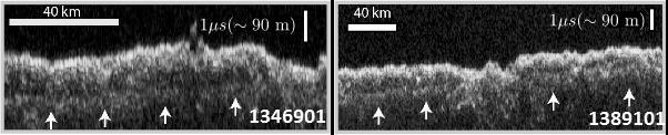
These two images show data acquired by the Shallow Radar (SHARAD) instrument while passing over two ground tracks in a part of Mars' Utopia Planitia region where the orbiting, ground-penetrating radar detected subsurface deposits rich in water ice. The instrument on NASA's Mars Reconnaissance Orbiter emits radio waves and times their echo off of radio-reflective surfaces and interfaces on Mars. The white arrows indicate a subsurface reflector interpreted as the bottom of the ice-rich deposit. The deposit is about as large in area as the state of New Mexico and contains about as much water as Lake Superior. The horizontal scale bar indicates 40 kilometers (25 miles) along the ground track of the radar, as flown by the orbiter overhead. The vertical scale bar indicates a return time of one microsecond for the reflected radio signal, equivalent to a distance of about 90 meters (295 feet). http://photojournal.jpl.nasa.gov/catalog/PIA21137
NASA’s Tracking and Data Relay Satellite (TDRS-H) sits poised on Launch Pad 36A, Cape Canaveral Air Force Station, before its scheduled launch aboard an Atlas IIA/Centaur rocket. One of three satellites (labeled H, I and J) being built by the Hughes Space and Communications Company, the latest TDRS uses an innovative springback antenna design. A pair of 15-foot-diameter, flexible mesh antenna reflectors fold up for launch, then spring back into their original cupped circular shape on orbit. The new satellites will augment the TDRS system’s existing Sand Ku-band frequencies by adding Ka-band capability. TDRS will serve as the sole means of continuous, high-data-rate communication with the space shuttle, with the International Space Station upon its completion, and with dozens of unmanned scientific satellites in low earth orbit
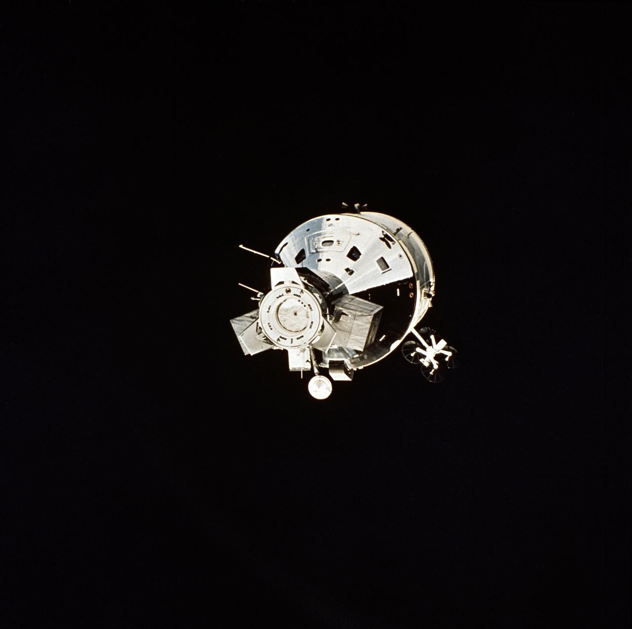
AST-32-2691 (17-19 July 1975) --- The American Apollo spacecraft as seen in Earth orbit from the Soviet Soyuz spacecraft during the joint U.S.-USSR Apollo-Soyuz Test Project mission. The Command/Service Module and Docking Module are contrasted against a black-sky background. This is a near "head on" view of the Apollo. This picture was furnished by the USSR in an exchange of photography taken during the ASTP flight. Note the docking mechanism and docking target on the Docking Module. The four dish-like reflectors of the unified S-band high-gain antenna protrude from the side of the Service Module. The American and Soviet spacecraft were joined together in space for approximately 47 hours on July 17-18-19, 1975. PHOTO COURTESY: USSR ACADEMY OF SCIENCES
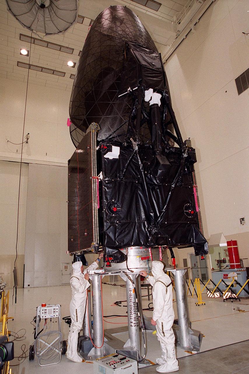
Workers in KSC’s Spacecraft Assembly and Encapsulation Facility (SAEF-2) conduct electrical testing on the Tracking and Data Relay Satellite (TDRS-H) above them. The TDRS is scheduled to be launched from CCAFS June 29 aboard an Atlas IIA/Centaur rocket. One of three satellites (labeled H, I and J) being built in the Hughes Space and Communications Company Integrated Satellite Factory in El Segundo, Calif., the latest TDRS uses an innovative springback antenna design. A pair of 15-foot-diameter, flexible mesh antenna reflectors fold up for launch, then spring back into their original cupped circular shape on orbit. The new satellites will augment the TDRS system’s existing Sand Ku-band frequencies by adding Ka-band capability. TDRS will serve as the sole means of continuous, high-data-rate communication with the space shuttle, with the International Space Station upon its completion, and with dozens of unmanned scientific satellites in low earth orbit

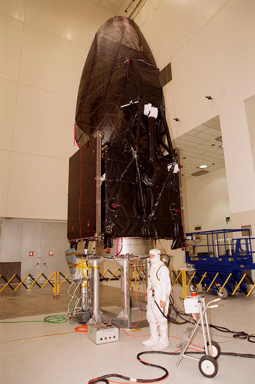
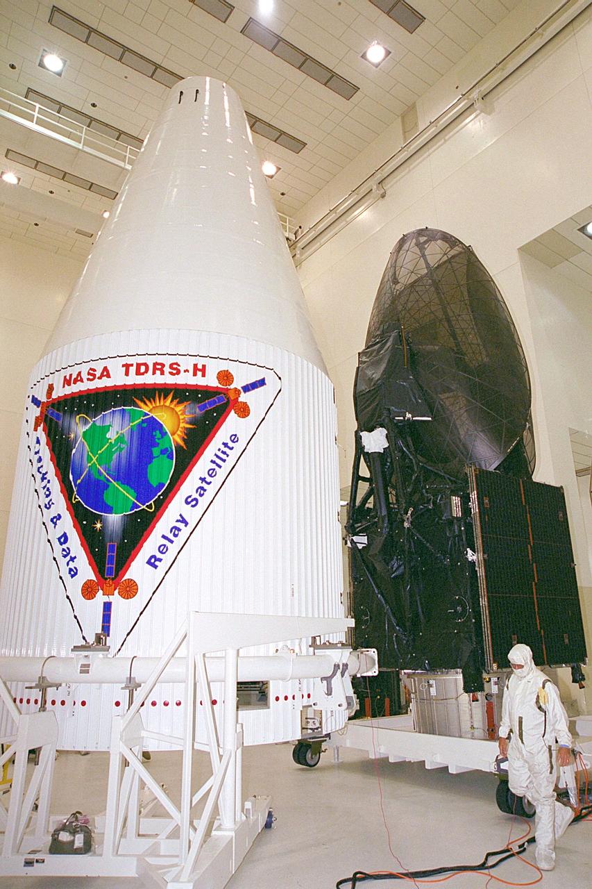
The Tracking and Data Relay Satellite (TDRS-H) sits fully encapsulated inside the fairing. Next, it will be transported to Launch Pad 36A, Cape Canaveral Air Force Station for launch scheduled June 29 aboard an Atlas IIA/Centaur rocket. One of three satellites (labeled H, I and J) being built in the Hughes Space and Communications Company Integrated Satellite Factory in El Segundo, Calif., the latest TDRS uses an innovative springback antenna design. A pair of 15-foot-diameter, flexible mesh antenna reflectors fold up for launch, then spring back into their original cupped circular shape on orbit. The new satellites will augment the TDRS system’s existing Sand Ku-band frequencies by adding Ka-band capability. TDRS will serve as the sole means of continuous, high-data-rate communication with the space shuttle, with the International Space Station upon its completion, and with dozens of unmanned scientific satellites in low earth orbit

MarCO-B, one of the experimental Mars Cube One (MarCO) CubeSats, took this image of Mars from about 10,900 miles (17,500 kilometers) away just after NASA’s InSight spacecraft landed on Mars on Nov. 26, 2018. MarCO-B flew by Mars with its twin, MarCO-A, to serve as communications relays for InSight as it touched down on the Red Planet around noon PST (3 p.m. EST). This image was taken at 1 p.m. PST (4 p.m. EST). Mars’ south pole is facing the viewer in this image. MarCO-B’s antenna reflector is on the right and antenna feed (white rectangle with gold square) is on the left. The Sun at upper right overexposed part of the image. This image was taken after PIA22833 and shortly before PIA22834. The MarCO and InSight projects are managed for NASA's Science Mission Directorate, Washington, by JPL, a division of Caltech, Pasadena. Credit: NASA/JPL-Caltech

MarCO-B, one of the experimental Mars Cube One (MarCO) CubeSats, took this image of Mars from about 10,900 miles (17,500 kilometers) away just after NASA's InSight spacecraft landed on Mars on Nov. 26, 2018. MarCO-B flew by Mars with its twin, MarCO-A, to serve as communications relays for InSight as it touched down on the Red Planet around noon PST (3 p.m. EST). This image was taken at 1 p.m. PST (4 p.m. EST). A crescent Mars with its south pole in the 4 o'clock position is visible in this picture. MarCO-B's antenna reflector mirrors a portion of the illuminated part of Mars on the bottom right. The antenna feed (white rectangle with gold squares) is visible on the left. https://photojournal.jpl.nasa.gov/catalog/PIA22834

After tower rollback just before dawn on Launch Pad 36A, Cape Canaveral Air Force Station, NASA’s Tracking and Data Relay Satellite (TDRS-H) sits bathed in spotlights before liftoff atop an Atlas IIA/Centaur rocket. One of three satellites (labeled H, I and J) being built by the Hughes Space and Communications Company, the latest TDRS uses an innovative springback antenna design. A pair of 15-foot-diameter, flexible mesh antenna reflectors fold up for launch, then spring back into their original cupped circular shape on orbit. The new satellites will augment the TDRS system’s existing Sand Ku-band frequencies by adding Ka-band capability. TDRS will serve as the sole means of continuous, high-data-rate communication with the Space Shuttle, with the International Space Station upon its completion, and with dozens of unmanned scientific satellites in low earth orbit
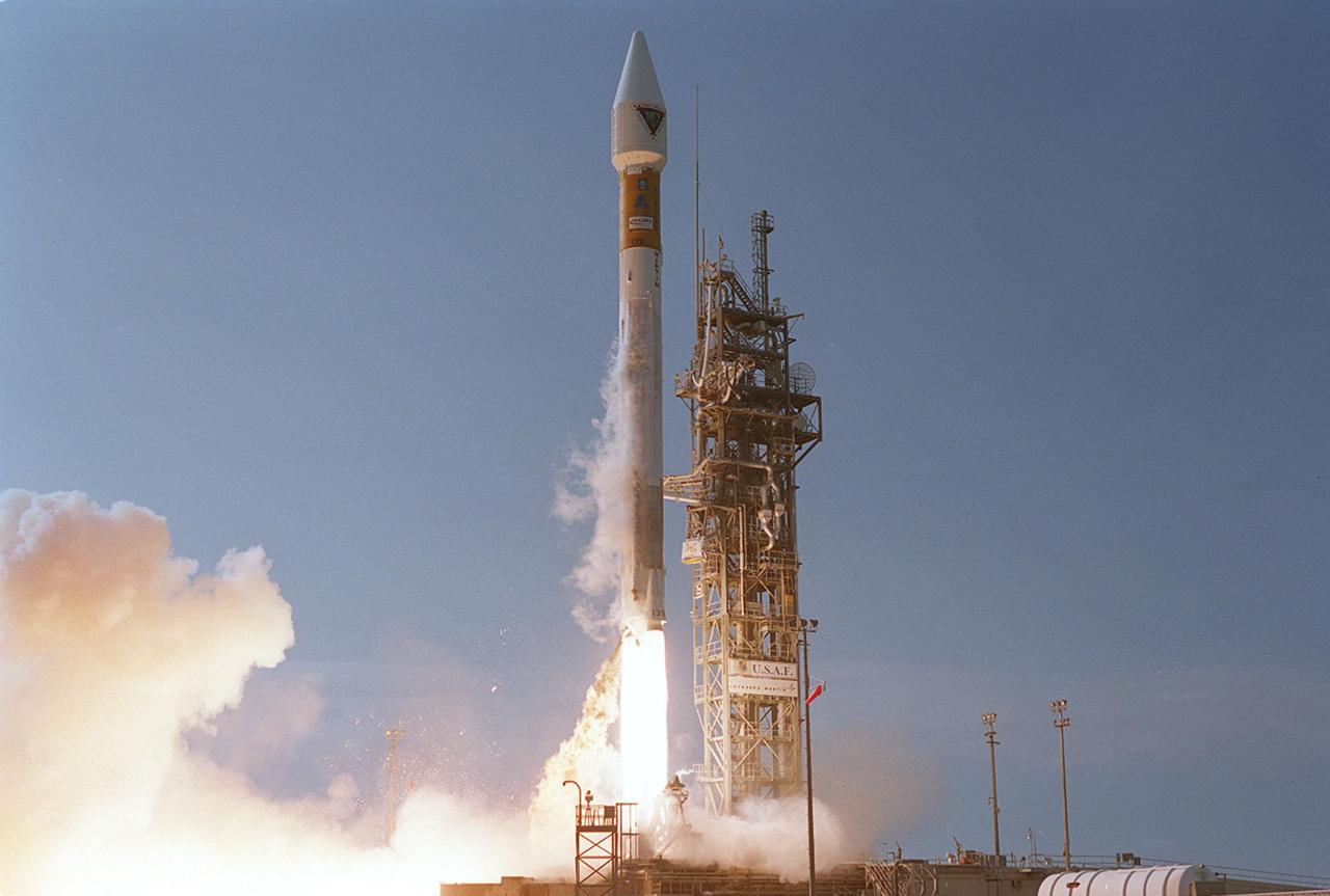
Leaving billowing clouds of steam and smoke behind, NASA’s Tracking and Data Relay Satellite (TDRS-H) shoots into the blue sky aboard an Atlas IIA/Centaur rocket from Pad 36A, Cape Canaveral Air Force Station. Liftoff occurred at 8:56 a.m. EDT. One of three satellites (labeled H, I and J) being built by the Hughes Space and Communications Company, the latest TDRS uses an innovative springback antenna design. A pair of 15-foot-diameter, flexible mesh antenna reflectors fold up for launch, then spring back into their original cupped circular shape on orbit. The new satellites will augment the TDRS system’s existing Sand Ku-band frequencies by adding Ka-band capability. TDRS will serve as the sole means of continuous, high-data-rate communication with the space shuttle, with the International Space Station upon its completion, and with dozens of unmanned scientific satellites in low earth orbit
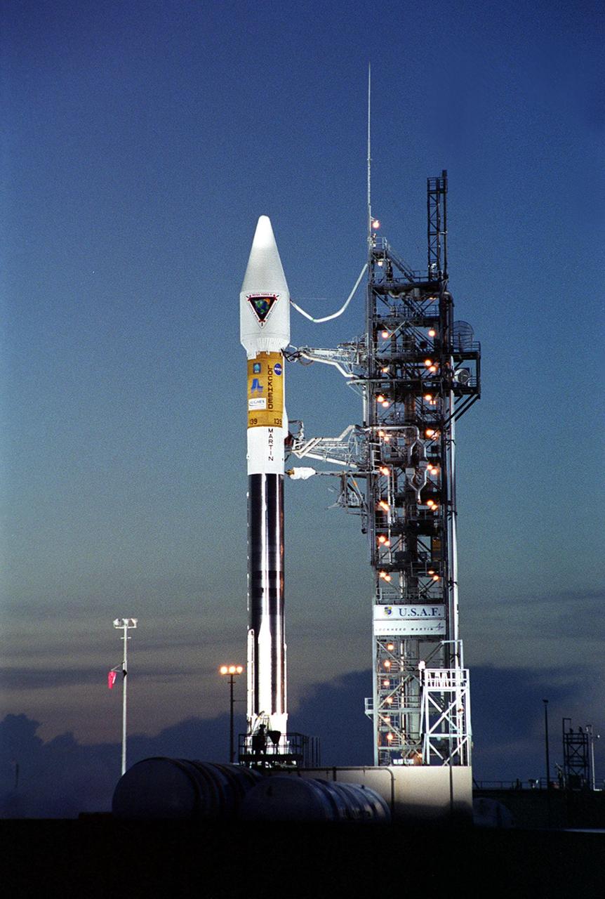
After tower rollback just before dawn on Launch Pad 36A, Cape Canaveral Air Force Station, NASA’s Tracking and Data Relay Satellite (TDRS-H) sits bathed in spotlights before liftoff atop an Atlas IIA/Centaur rocket. One of three satellites (labeled H, I and J) being built by the Hughes Space and Communications Company, the latest TDRS uses an innovative springback antenna design. A pair of 15-foot-diameter, flexible mesh antenna reflectors fold up for launch, then spring back into their original cupped circular shape on orbit. The new satellites will augment the TDRS system’s existing Sand Ku-band frequencies by adding Ka-band capability. TDRS will serve as the sole means of continuous, high-data-rate communication with the Space Shuttle, with the International Space Station upon its completion, and with dozens of unmanned scientific satellites in low earth orbit
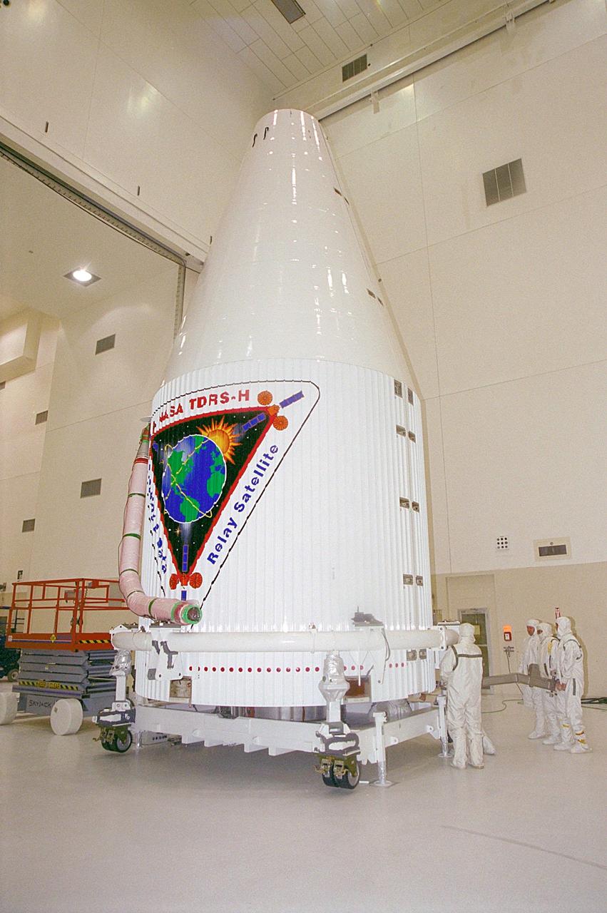
The Tracking and Data Relay Satellite (TDRS-H) sits fully encapsulated inside the fairing. Next, it will be transported to Launch Pad 36A, Cape Canaveral Air Force Station for launch scheduled June 29 aboard an Atlas IIA/Centaur rocket. One of three satellites (labeled H, I and J) being built in the Hughes Space and Communications Company Integrated Satellite Factory in El Segundo, Calif., the latest TDRS uses an innovative springback antenna design. A pair of 15-foot-diameter, flexible mesh antenna reflectors fold up for launch, then spring back into their original cupped circular shape on orbit. The new satellites will augment the TDRS system’s existing Sand Ku-band frequencies by adding Ka-band capability. TDRS will serve as the sole means of continuous, high-data-rate communication with the space shuttle, with the International Space Station upon its completion, and with dozens of unmanned scientific satellites in low earth orbit
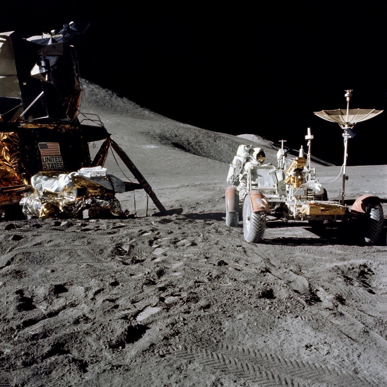
AS15-86-11602 (31 July 1971) --- Astronaut James B. Irwin, lunar module pilot, works at the Lunar Roving Vehicle (LRV) during the first Apollo 15 lunar surface extravehicular activity (EVA) at the Hadley-Apennine landing site. A portion of the Lunar Module (LM) "Falcon" is on the left. The undeployed Laser Ranging Retro Reflector (LR-3) lies atop the LM's modular equipment stowage assembly (MESA). This view is looking slightly west of south. Hadley Delta and the Apennine Front are in the background to the left. St. George crater is approximately five kilometers (about three statute miles) in the distance behind Irwin's head. This photograph was taken by astronaut David R. Scott, commander. While astronauts Scott and Irwin descended in the LM to explore the moon, astronaut Alfred M. Worden, command module pilot, remained with the Command and Service Modules (CSM) in lunar orbit.
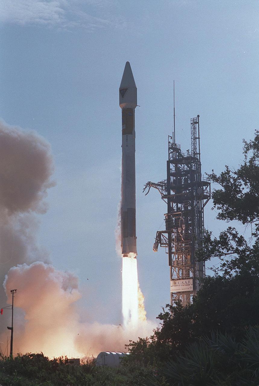
NASA’s Tracking and Data Relay Satellite (TDRS-H) rises into the blue sky from Pad 36A, Cape Canaveral Air Force Station. Liftoff occurred at 8:56 a.m. EDT aboard an Atlas IIA/Centaur rocket. One of three satellites (labeled H, I and J) being built by the Hughes Space and Communications Company, the latest TDRS uses an innovative springback antenna design. A pair of 15-foot-diameter, flexible mesh antenna reflectors fold up for launch, then spring back into their original cupped circular shape on orbit. The new satellites will augment the TDRS system’s existing Sand Ku-band frequencies by adding Ka-band capability. TDRS will serve as the sole means of continuous, high-data-rate communication with the space shuttle, with the International Space Station upon its completion, and with dozens of unmanned scientific satellites in low earth orbit
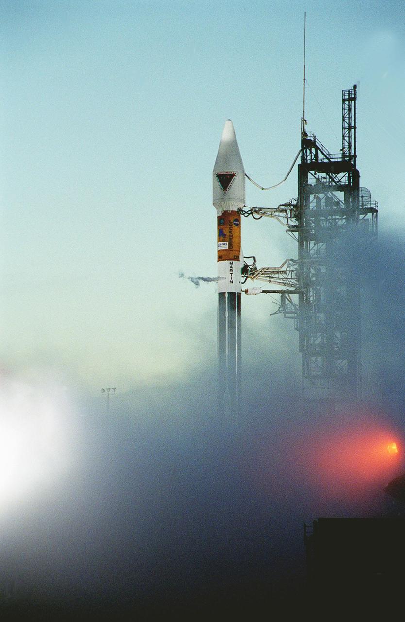
At dawn on Launch Pad 36A, Cape Canaveral Air Force Station, an Atlas IIA/Centaur rocket is fueled for launch of NASA’s Tracking and Data Relay Satellite (TDRS-H). One of three satellites (labeled H, I and J) being built by the Hughes Space and Communications Company, the latest TDRS uses an innovative springback antenna design. A pair of 15-foot-diameter, flexible mesh antenna reflectors fold up for launch, then spring back into their original cupped circular shape on orbit. The new satellites will augment the TDRS system’s existing Sand Ku-band frequencies by adding Ka-band capability. TDRS will serve as the sole means of continuous, high-data-rate communication with the Space Shuttle, with the International Space Station upon its completion, and with dozens of unmanned scientific satellites in low earth orbit

NASA’s Tracking and Data Relay Satellite (TDRS-H) rises into the blue sky from Pad 36A, Cape Canaveral Air Force Station. Liftoff occurred at 8:56 a.m. EDT aboard an Atlas IIA/Centaur rocket. One of three satellites (labeled H, I and J) being built by the Hughes Space and Communications Company, the latest TDRS uses an innovative springback antenna design. A pair of 15-foot-diameter, flexible mesh antenna reflectors fold up for launch, then spring back into their original cupped circular shape on orbit. The new satellites will augment the TDRS system’s existing Sand Ku-band frequencies by adding Ka-band capability. TDRS will serve as the sole means of continuous, high-data-rate communication with the space shuttle, with the International Space Station upon its completion, and with dozens of unmanned scientific satellites in low earth orbit

NASA’s Tracking and Data Relay Satellite (TDRS-H) rises into the blue sky from Pad 36A, Cape Canaveral Air Force Station. Liftoff occurred at 8:56 a.m. EDT aboard an Atlas IIA/Centaur rocket. One of three satellites (labeled H, I and J) being built by the Hughes Space and Communications Company, the latest TDRS uses an innovative springback antenna design. A pair of 15-foot-diameter, flexible mesh antenna reflectors fold up for launch, then spring back into their original cupped circular shape on orbit. The new satellites will augment the TDRS system’s existing Sand Ku-band frequencies by adding Ka-band capability. TDRS will serve as the sole means of continuous, high-data-rate communication with the space shuttle, with the International Space Station upon its completion, and with dozens of unmanned scientific satellites in low earth orbit

In the early morning hours, NASA’s Tracking and Data Relay Satellite (TDRS-H) sits poised on Launch Pad 36A, Cape Canaveral Air Force Station, before its scheduled launch aboard an Atlas IIA/Centaur rocket. One of three satellites (labeled H, I and J) being built by the Hughes Space and Communications Company, the latest TDRS uses an innovative springback antenna design. A pair of 15-foot-diameter, flexible mesh antenna reflectors fold up for launch, then spring back into their original cupped circular shape on orbit. The new satellites will augment the TDRS system’s existing Sand Ku-band frequencies by adding Ka-band capability. TDRS will serve as the sole means of continuous, high-data-rate communication with the Space Shuttle, with the International Space Station upon its completion, and with dozens of unmanned scientific satellites in low earth orbit
Workers in KSC’s Spacecraft Assembly and Encapsulation Facility (SAEF-2) prepare the Tracking and Data Relay Satellite (TDRS-H) above them for electrical testing. The TDRS is scheduled to be launched from CCAFS June 29 aboard an Atlas IIA/Centaur rocket. One of three satellites (labeled H, I and J) being built in the Hughes Space and Communications Company Integrated Satellite Factory in El Segundo, Calif., the latest TDRS uses an innovative springback antenna design. A pair of 15-foot-diameter, flexible mesh antenna reflectors fold up for launch, then spring back into their original cupped circular shape on orbit. The new satellites will augment the TDRS system’s existing Sand Ku-band frequencies by adding Ka-band capability. TDRS will serve as the sole means of continuous, high-data-rate communication with the space shuttle, with the International Space Station upon its completion, and with dozens of unmanned scientific satellites in low earth orbit
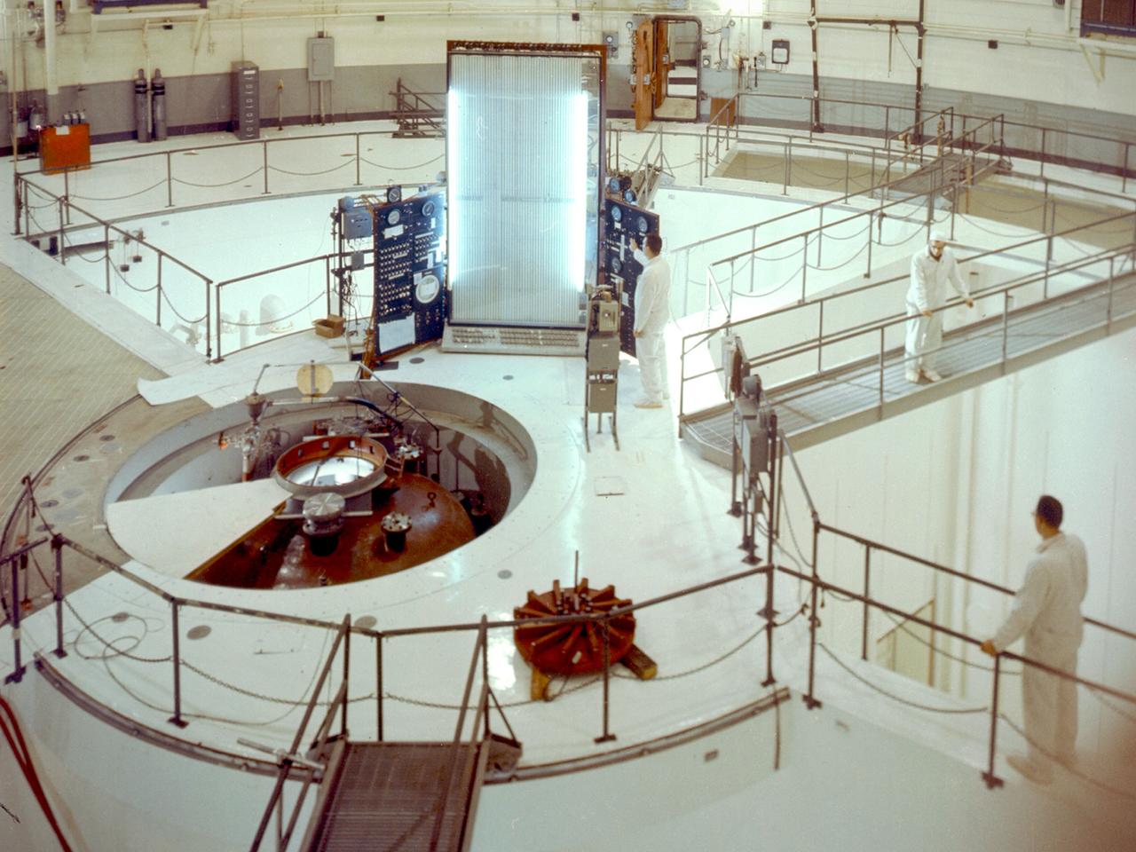
A view inside the 55-foot high containment vessel of the National Aeronautics and Space Administration (NASA) Plum Brook Reactor Facility in Sandusky, Ohio. The 60-megawatt test reactor went critical for the first time in 1961 and began its full-power research operations in 1963. From 1961 to 1973, this reactor performed some of the nation’s most advanced nuclear research. The reactor was designed to determine the behavior of metals and other materials after long durations of irradiation. The materials would be used to construct a nuclear-powered rocket. The reactor core, where the chain reaction occurred, sat at the bottom of the tubular pressure vessel, seen here at the center of the shielding pool. The core contained fuel rods with uranium isotopes. A cooling system was needed to reduce the heat levels during the reaction. A neutron-impervious reflector was also employed to send many of the neutrons back to the core. The Plum Brook Reactor Facility was constructed from high-density concrete and steel to prevent the excess neutrons from escaping the facility, but the water in the pool shielded most of the radiation. The water, found in three of the four quadrants served as a reflector, moderator, and coolant. In this photograph, the three 20-ton protective shrapnel shields and hatch have been removed from the top of the pressure tank revealing the reactor tank. An overhead crane could be manipulated to reach any section of this room. It was used to remove the shrapnel shields and transfer equipment.
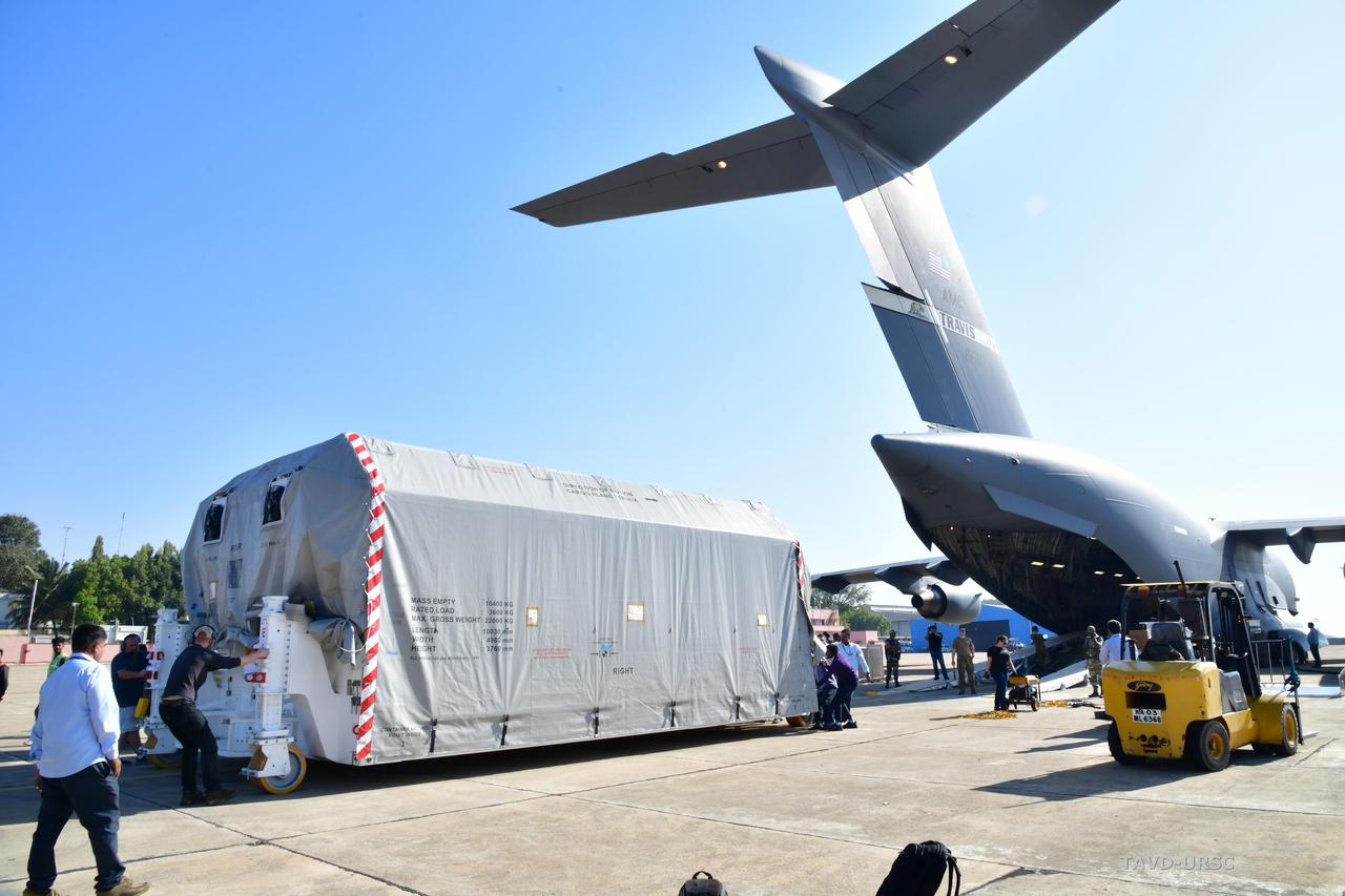
The NASA-ISRO Synthetic Aperture Radar (NISAR) science instrument payload, housed in a specially designed shipping container, sits at Hindustan Aeronautics Limited Airport in Bengaluru, India. The payload left NASA's Jet Propulsion Laboratory in Southern California on Feb. 28, and departed the United States on March 3 aboard a U.S. Air Force cargo plane, arriving in Bengaluru on March 6. From there it was transported to the Indian Space Research Organisation's U R Rao Satellite Centre, where it will be integrated with the satellite body, or bus, and undergo further testing leading up to launch in 2024. The NISAR mission – a joint effort between NASA and the Indian Space Research Organisation – will observe nearly all the planet's land and ice surfaces twice every 12 days, measuring movements in extremely fine detail. It will also survey forests and agricultural regions to understand carbon exchange between plants and the atmosphere. NISAR's science payload will be the most advanced radar system ever launched as part of a NASA mission, and it will feature the largest-ever radar antenna of its kind: a drum-shaped, wire mesh reflector nearly 40 feet (12 meters) in diameter that will extend from a 30-foot (9-meter) boom. The mission's science instruments consist of L- and S-band radar, so named to indicate the wavelengths of their signals. ISRO built the S-band radar, which it shipped to JPL in March 2021. Engineers spent much of the last two years integrating the instrument with the JPL-built L-band system, then conducting tests to verify they work well together. JPL, which is managed for NASA by Caltech in Pasadena, leads the U.S. component of NISAR. In addition to the L-band radar, NASA is also providing the radar reflector antenna, the deployable boom, a high-rate communication subsystem for science data, GPS receivers, a solid-state recorder, and payload data subsystem. In addition to the S-band radar, ISRO is providing the spacecraft bus, the launch vehicle, and associated launch services and satellite mission operations. https://photojournal.jpl.nasa.gov/catalog/PIA25570
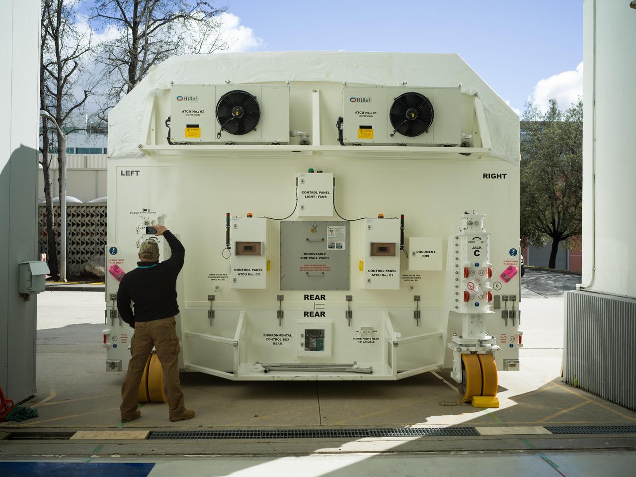
A specially designed, climate-controlled shipping container holding the NASA-ISRO Synthetic Aperture Radar (NISAR) science instrument payload sits outside an airlock at the Spacecraft Assembly Facility at NASA's Jet Propulsion Laboratory on Feb. 26, 2023. The payload was shipped to Bengaluru, India, on March 3, arriving on March 6. There it will be integrated with the satellite body, or bus, and undergo further testing leading up to launch in 2024. The NISAR mission – a joint effort between NASA and the Indian Space Research Organisation – will observe nearly all the planet's land and ice surfaces twice every 12 days, measuring movements in extremely fine detail. It will also survey forests and agricultural regions to understand carbon exchange between plants and the atmosphere. NISAR's science payload will be the most advanced radar system ever launched as part of a NASA mission, and it will feature the largest-ever radar antenna of its kind: a drum-shaped, wire mesh reflector nearly 40 feet (12 meters) in diameter that will extend from a 30-foot (9-meter) boom. The mission's science instruments consist of L- and S-band radar, so named to indicate the wavelengths of their signals. ISRO built the S-band radar, which it shipped to JPL in March 2021. Engineers spent much of the last two years integrating the instrument with the JPL-built L-band system, then conducting tests to verify they work well together. JPL, which is managed for NASA by Caltech in Pasadena, leads the U.S. component of NISAR. In addition to the L-band radar, NASA is also providing the radar reflector antenna, the deployable boom, a high-rate communication subsystem for science data, GPS receivers, a solid-state recorder, and payload data subsystem. In addition to the S-band radar, ISRO is providing the spacecraft bus, the launch vehicle, and associated launch services and satellite mission operations. https://photojournal.jpl.nasa.gov/catalog/PIA25568
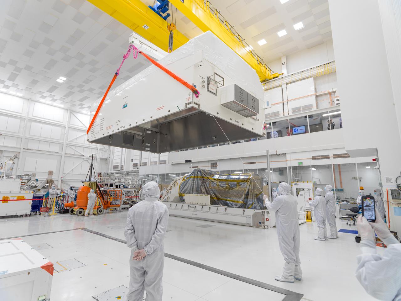
In a clean room at NASA's Jet Propulsion Laboratory on Feb. 23, 2023, engineers and technicians use a crane to prepare to seal a specially designed, climate-controlled shipping container holding the NASA-ISRO Synthetic Aperture Radar (NISAR) science instrument payload. The payload was then shipped to Bengaluru, India, on March 3, arriving on March 6. There it will be integrated with the satellite body, or bus, and undergo further testing leading up to launch in 2024. The NISAR mission – a joint effort between NASA and the Indian Space Research Organisation – will observe nearly all the planet's land and ice surfaces twice every 12 days, measuring movements in extremely fine detail. It will also survey forests and agricultural regions to understand carbon exchange between plants and the atmosphere. NISAR's science payload will be the most advanced radar system ever launched as part of a NASA mission, and it will feature the largest-ever radar antenna of its kind: a drum-shaped, wire mesh reflector nearly 40 feet (12 meters) in diameter that will extend from a 30-foot (9-meter) boom. The mission's science instruments consist of L- and S-band radar, so named to indicate the wavelengths of their signals. ISRO built the S-band radar, which it shipped to JPL in March 2021. Engineers spent much of the last two years integrating the instrument with the JPL-built L-band system, then conducting tests to verify they work well together. JPL, which is managed for NASA by Caltech in Pasadena, leads the U.S. component of NISAR. In addition to the L-band radar, NASA is also providing the radar reflector antenna, the deployable boom, a high-rate communication subsystem for science data, GPS receivers, a solid-state recorder, and payload data subsystem. In addition to the S-band radar, ISRO is providing the spacecraft bus, the launch vehicle, and associated launch services and satellite mission operations. https://photojournal.jpl.nasa.gov/catalog/PIA25567
The NASA-ISRO Synthetic Aperture Radar (NISAR) science instrument payload sits in its specially designed, climate-controlled shipping container in a clean room at NASA's Jet Propulsion Laboratory on Feb. 23, 2023. Engineers and technicians used a crane to lift the payload and mount it vertically onto a stage at the far end of the container before tilting it horizontally. The payload was then shipped to Bengaluru, India, on March 3, arriving on March 6. There it will be integrated with the satellite body, or bus, and undergo further testing leading up to launch in 2024. The NISAR mission – a joint effort between NASA and the Indian Space Research Organisation – will observe nearly all the planet's land and ice surfaces twice every 12 days, measuring movements in extremely fine detail. It will also survey forests and agricultural regions to understand carbon exchange between plants and the atmosphere. NISAR's science payload will be the most advanced radar system ever launched as part of a NASA mission, and it will feature the largest-ever radar antenna of its kind: a drum-shaped, wire mesh reflector nearly 40 feet (12 meters) in diameter that will extend from a 30-foot (9-meter) boom. The mission's science instruments consist of L- and S-band radar, so named to indicate the wavelengths of their signals. ISRO built the S-band radar, which it shipped to JPL in March 2021. Engineers spent much of the last two years integrating the instrument with the JPL-built L-band system, then conducting tests to verify they work well together. JPL, which is managed for NASA by Caltech in Pasadena, leads the U.S. component of NISAR. In addition to the L-band radar, NASA is also providing the radar reflector antenna, the deployable boom, a high-rate communication subsystem for science data, GPS receivers, a solid-state recorder, and payload data subsystem. In addition to the S-band radar, ISRO is providing the spacecraft bus, the launch vehicle, and associated launch services and satellite mission operations. https://photojournal.jpl.nasa.gov/catalog/PIA25566
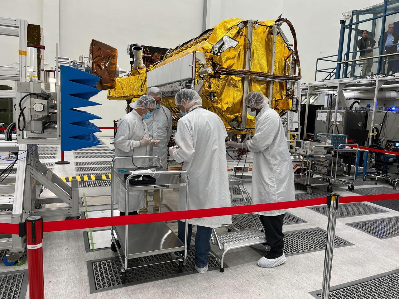
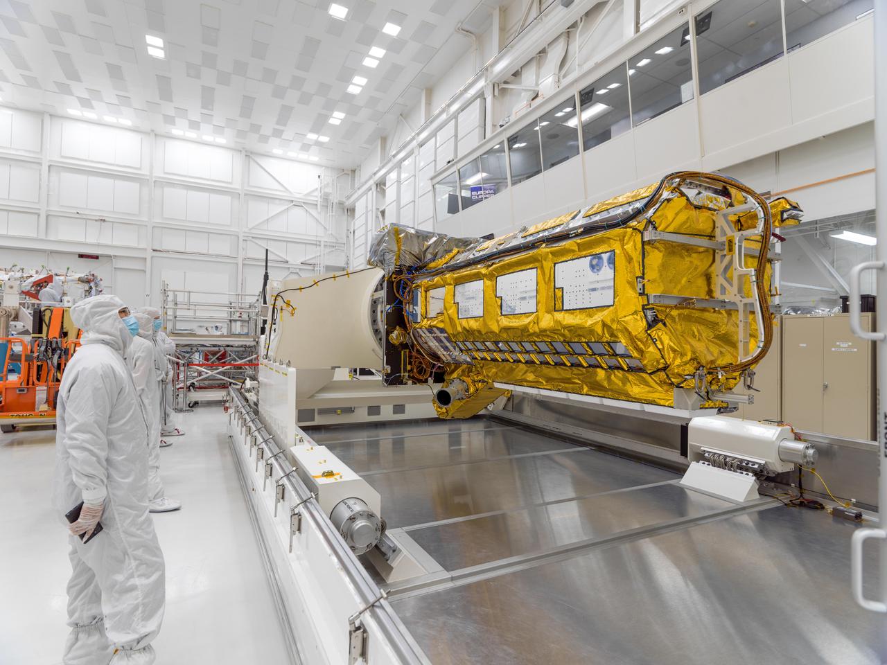
Engineers and technicians from NASA's Jet Propulsion Laboratory work on the NASA-ISRO Synthetic Aperture Radar (NISAR) science instrument payload in a clean room at JPL on Feb. 3, 2023. The payload is scheduled to ship to India in March 2023. The NISAR mission – a joint effort between NASA and ISRO – will measure changes to Earth's land ice surfaces down to fractions of an inch. Data collected by this satellite will help researchers monitor a wide range of changes critical to life on Earth in unprecedented detail. This includes spotting warning signs of imminent volcanic eruptions, helping to monitor groundwater supplies, tracking the melt rate of ice sheets tied to sea level rise, and observing shifts in the distribution of vegetation around the world. The data will inform humanity's responses to urgent challenges posed by natural disasters and climate change, and help communities prepare for and manage hazards. There are two instruments on the satellite that will send and receive radar signals to and from Earth's surface to make the mission's measurements. An L-band synthetic aperture radar (SAR), which uses a signal wavelength of around 9 inches (24 centimeters), and an S-band SAR with a signal wavelength of nearly 5 inches (12 centimeters). Both will bounce their microwave signal off of the planet's surface and record how long it takes the signal to make one roundtrip, as well as the strength of that return signal. This enables the researchers to calculate the distance from the spacecraft to Earth's surface and thereby determine how the land or ice is changing. An antenna reflector nearly 40 feet (12 meters) in diameter, supported by a deployable boom, will focus the microwave signals sent and received by the SARs. JPL, which is managed for NASA by Caltech in Pasadena, leads the U.S. component of NISAR and is providing the mission's L-band SAR instrument. NASA is also providing the radar reflector antenna, the deployable boom, a high-rate communication subsystem for science data, GPS receivers, a solid-state recorder, and payload data subsystem. ISRO is providing the spacecraft bus, the S-band SAR, the launch vehicle, and associated launch services and satellite mission operations. https://photojournal.jpl.nasa.gov/catalog/PIA25771

This is a digital elevation model that was geometrically coded directly onto an X-band seasonal change image of the Oetztal supersite in Austria. The image is centered at 46.82 degrees north latitude and 10.79 degrees east longitude. This image is located in the Central Alps at the border between Switzerland, Italy and Austria, 50 kilometers (31 miles) southwest of Innsbruck. It was acquired by the Spaceborne Imaging Radar-C/X-band Synthetic Aperture aboard the space shuttle Endeavour on April 14, 1994 and on October 5, 1994. It was produced by combining data from these two different data sets. Data obtained in April is green; data obtained in October appears in red and blue, and was used as an enhancement based on the ratio of the two data sets. Areas with a decrease in backscatter from April to October appear in light blue (cyan), such as the large Gepatschferner glacier seen at the left of the image center, and most of the other glaciers in this view. A light blue hue is also visible at the east border of the dark blue Lake Reschensee at the upper left side. This shows a significant rise in the water level. Magenta represents areas with an increase of backscatter from April 10 to October 5. Yellow indicates areas with high radar signal response during both passes, such as the mountain slopes facing the radar. Low radar backscatter signals refer to smooth surface (lakes) or radar grazing areas to radar shadow areas, seen in the southeast slopes. The area is approximately 29 kilometers by 21 kilometers (18 miles by 13.5 miles). The summit of the main peaks reaches elevations of 3,500 to 3,768 meters (xx feet to xx feet) above sea level. The test site's core area is the glacier region of Venter Valley, which is one of the most intensively studied areas for glacier research in the world. Research in Venter Valley (below center) includes studies of glacier dynamics, glacier-climate regions, snowpack conditions and glacier hydrology. About 25 percent of the core test site is covered by glaciers. Corner reflectors are set up for calibration. Five corner reflectors can be seen on the Gepatschferner and two can be seen on the Vernagtferner. http://photojournal.jpl.nasa.gov/catalog/PIA01760
STS059-S-026 (11 April 1994) --- This is an image of Death Valley, California, centered at 36.629 degrees north latitude, 117.069 degrees west longitude. The image shows Furnace Creek alluvial fan and Furnace Creek Ranch at the far right, and the sand dunes near Stove Pipe Wells at the center. The dark fork-shaped feature between Furnace Creek fan and the dunes is a smooth flood-plain which encloses Cottonball Basin. The SIR-C/X-SAR supersite is an area of extensive field investigations and has been visited by both Space Radar Lab astronaut crews. Elevations in the Valley range from 70 meters below sea level, the lowest in the United States, to more than 3300 meters above sea level. Scientists are using SIR-C/X-SAR data from Death Valley to help answer a number of different questions about the Earth's geology. One question concerns how alluvial fans are formed and change through time under the influence of climatic changes and earthquakes. Alluvial fans are gravel deposits that wash down from the mountains over time. They are visible in the image as circular, fan-shaped bright areas extending into the darker valley floor from the mountains. Information about the alluvial fans help scientists study Earth's ancient climate. Scientists know the fans are bulit up through climatic and tectonic processes and they will use the SIR-C/X-SAR data to understand the nature and rates of weathering processes on the fans, soil formation, and the transport of sand and dust by the wind. SIR-C/X-SAR's sensitivity to centimeter-scale (or inch-scale) roughness provides detailed maps of surface texture. Such information can be used to study the occurrence and movement of dust storms and sand dunes. the goal of these studies is to gain a better understanding of the record of past climatic changes and the effects of those changes on a sensitive environment. This may lead to a better ability to predict future response of the land to different potential global cimate-change scenarios. Death Valley is also one of the primary calibration sites for SIR-C/X-SAR. The bright dots near the center of the image are corner reflectors that have been set-up to calibrate the radar as the Shuttle passes overhead. Thirty triangular-shaped reflectors (they look like aluminum pyramids) have been deployed by the calibration team from JPL over a 40 kilometer by 40 kilometer area in and around Death Valley. The calibration team will also deploy transponders (electronic reflectors) and recievers to measure the radar signals from SIR-C/X-SAR on the ground. Spaceborne Imaging Radar-C and X-Synthetic Aperture Radar (SIR-C/X-SAR) is part of NASA's Mission to Planet Earth (MTPE). The radars illuminate Earth with microwaves allowing detailed observations at any time, regardless of weather or sunlight conditions. SIR-C/X-SAR uses three microwave wavelengths: L-Band (24 cm), C-Band (6 cm), and X-Band (3 cm). The multi-frequency data will be used by the international scientific community to better understand the global environment and how it is changing. The SIR-C/X-SAR data, complemented by aircraft and ground studies, will give scientists clearer insights into those environmental changes which are caused by nature and those changes which are induced by human activity. SIR-C was develpoed by NASA's Jet Propulsion Laboratory (JPL). X-SAR was developed by the Dornire and Alenia Spazio Companies for the German Space Agency, Deutsche Agentur fuer Raumfahrtangelegenheiten (DARA), and the Italian Space Agency, Agenzia Spaziale Italiana (ASI). JPL Photo ID: P-43883
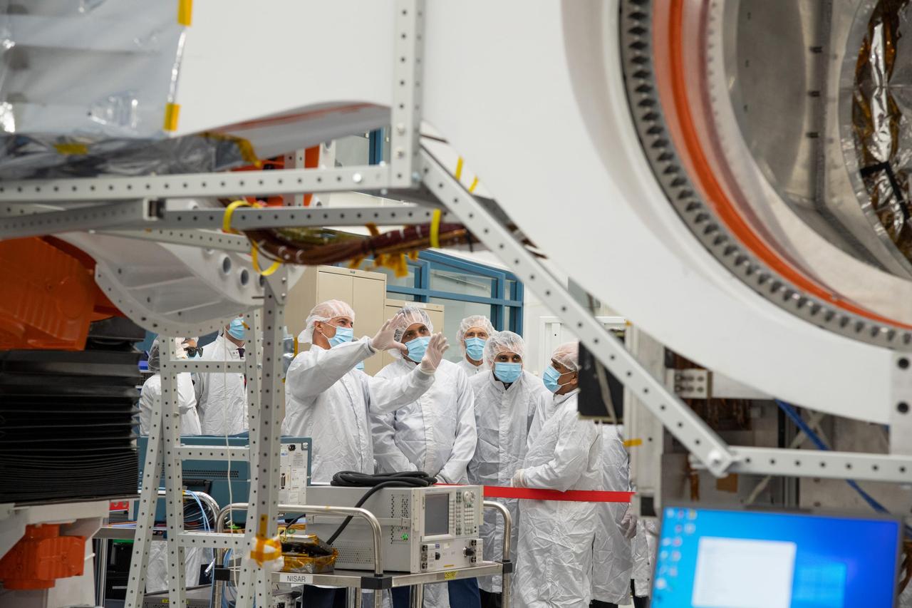
NASA's NISAR Project Manager Phil Barela (with hands raised) speaks with Indian Space Research Organisation Chairman S. Somanath about the NASA-ISRO Synthetic Aperture Radar (NISAR) science instrument payload in a clean room at NASA's Jet Propulsion Laboratory in Southern California on Feb. 3, 2023. Somanath was among a group of visitors to the facility that included officials from NASA, ISRO, and the Indian Embassy. The NISAR mission – a joint effort between NASA and ISRO – will measure changes to Earth's land ice surfaces down to fractions of an inch. Data collected by this satellite will help researchers monitor a wide range of changes critical to life on Earth in unprecedented detail. This includes spotting warning signs of imminent volcanic eruptions, helping to monitor groundwater supplies, tracking the melt rate of ice sheets tied to sea level rise, and observing shifts in the distribution of vegetation around the world. The data will inform humanity's responses to urgent challenges posed by natural disasters and climate change, and help communities prepare for and manage hazards. There are two instruments on the satellite that will send and receive radar signals to and from Earth's surface to make the mission's measurements. An L-band synthetic aperture radar (SAR), which uses a signal wavelength of around 9 inches (24 centimeters), and an S-band SAR with a signal wavelength of nearly 5 inches (12 centimeters). Both will bounce their microwave signal off of the planet's surface and record how long it takes the signal to make one roundtrip, as well as the strength of that return signal. This enables the researchers to calculate the distance from the spacecraft to Earth's surface and thereby determine how the land or ice is changing. An antenna reflector nearly 40 feet (12 meters) in diameter, supported by a deployable boom, will focus the microwave signals sent and received by the SARs. JPL, which is managed for NASA by Caltech in Pasadena, leads the U.S. component of NISAR and is providing the mission's L-band SAR instrument. NASA is also providing the radar reflector antenna, the deployable boom, a high-rate communication subsystem for science data, GPS receivers, a solid-state recorder, and payload data subsystem. ISRO is providing the spacecraft bus, the S-band SAR, the launch vehicle, and associated launch services and satellite mission operations. https://photojournal.jpl.nasa.gov/catalog/PIA25598
Officials from NASA, the Indian Space Research Organisation, and the Indian Embassy, grouped at left, visit a clean room at NASA's Jet Propulsion Laboratory in Southern California on Feb. 3, 2023, to view the scientific instrument payload for the NASA-ISRO Synthetic Aperture Radar (NISAR) mission. The payload is scheduled to be shipped to India in March 2023. The NISAR mission – a joint effort between NASA and ISRO – will measure changes to Earth's land ice surfaces down to fractions of an inch. Data collected by this satellite will help researchers monitor a wide range of changes critical to life on Earth in unprecedented detail. This includes spotting warning signs of imminent volcanic eruptions, helping to monitor groundwater supplies, tracking the melt rate of ice sheets tied to sea level rise, and observing shifts in the distribution of vegetation around the world. The data will inform humanity's responses to urgent challenges posed by natural disasters and climate change, and help communities prepare for and manage hazards. There are two instruments on the satellite that will send and receive radar signals to and from Earth's surface to make the mission's measurements. An L-band synthetic aperture radar (SAR), which uses a signal wavelength of around 9 inches (24 centimeters), and an S-band SAR with a signal wavelength of nearly 5 inches (12 centimeters). Both will bounce their microwave signal off of the planet's surface and record how long it takes the signal to make one roundtrip, as well as the strength of that return signal. This enables the researchers to calculate the distance from the spacecraft to Earth's surface and thereby determine how the land or ice is changing. An antenna reflector nearly 40 feet (12 meters) in diameter, supported by a deployable boom, will focus the microwave signals sent and received by the SARs. JPL, which is managed for NASA by Caltech in Pasadena, leads the U.S. component of NISAR and is providing the mission's L-band SAR instrument. NASA is also providing the radar reflector antenna, the deployable boom, a high-rate communication subsystem for science data, GPS receivers, a solid-state recorder, and payload data subsystem. ISRO is providing the spacecraft bus, the S-band SAR, the launch vehicle, and associated launch services and satellite mission operations. https://photojournal.jpl.nasa.gov/catalog/PIA25599
In the Spacecraft Assembly and Encapsulation Facility, the Tracking and Data Relay Satellite (TDRS-H) at right sits while one-half of the fairing (left) is moved closer to it. After encapsulation in the fairing, TDRS will be transported to Launch Pad 36A, Cape Canaveral Air Force Station for launch scheduled June 29 aboard an Atlas IIA/Centaur rocket. One of three satellites (labeled H, I and J) being built in the Hughes Space and Communications Company Integrated Satellite Factory in El Segundo, Calif., the latest TDRS uses an innovative springback antenna design. A pair of 15-foot-diameter, flexible mesh antenna reflectors fold up for launch, then spring back into their original cupped circular shape on orbit. The new satellites will augment the TDRS system’s existing Sand Ku-band frequencies by adding Ka-band capability. TDRS will serve as the sole means of continuous, high-data-rate communication with the space shuttle, with the International Space Station upon its completion, and with dozens of unmanned scientific satellites in low earth orbit
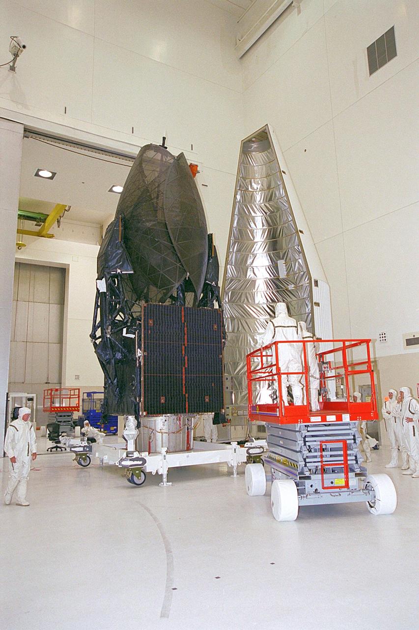
In the Spacecraft Assembly and Encapsulation Facility, the Tracking and Data Relay Satellite (TDRS-H) at left is ready for encapsulation. Workers in an extendable platform wait for the fairing (right) to move into place. After encapsulation in the fairing, TDRS will be transported to Launch Pad 36A, Cape Canaveral Air Force Station for launch scheduled June 29 aboard an Atlas IIA/Centaur rocket. One of three satellites (labeled H, I and J) being built in the Hughes Space and Communications Company Integrated Satellite Factory in El Segundo, Calif., the latest TDRS uses an innovative springback antenna design. A pair of 15-foot-diameter, flexible mesh antenna reflectors fold up for launch, then spring back into their original cupped circular shape on orbit. The new satellites will augment the TDRS system’s existing Sand Ku-band frequencies by adding Ka-band capability. TDRS will serve as the sole means of continuous, high-data-rate communication with the space shuttle, with the International Space Station upon its completion, and with dozens of unmanned scientific satellites in low earth orbit
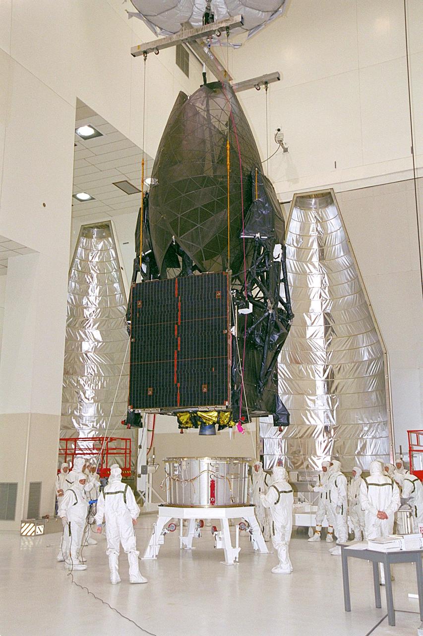
In the Spacecraft Assembly and Encapsulation Facility, overhead cranes lower the Tracking and Data Relay Satellite (TDRS-H) onto a payload adapter. Next step is the encapsulation of the satellite in the fairing behind it (right and left). TDRS is scheduled to be launched June 29 aboard an Atlas IIA/Centaur rocket. One of three satellites (labeled H, I and J) being built in the Hughes Space and Communications Company Integrated Satellite Factory in El Segundo, Calif., the latest TDRS uses an innovative springback antenna design. A pair of 15-foot-diameter, flexible mesh antenna reflectors fold up for launch, then spring back into their original cupped circular shape on orbit. The new satellites will augment the TDRS system’s existing Sand Ku-band frequencies by adding Ka-band capability. TDRS will serve as the sole means of continuous, high-data-rate communication with the space shuttle, with the International Space Station upon its completion, and with dozens of unmanned scientific satellites in low earth orbit

KENNEDY SPACE CENTER, FLA. -- The Microwave Anisotropy Probe (MAP) satellite arrives at Kennedy Space Center. The Vehicle Assembly Building is in the background. MAP is scheduled to launch on June 30 from Cape Canaveral Air Force Station on a Delta II rocket into a lunar-assisted trajectory to the Sun-Earth for a 27-month mission (3 months transit, 24 months observing). The MAP instrument consists of a set of passively cooled microwave radiometers with 1.4x 1.6-meter diameter primary reflectors to provide the desired angular resolution. MAP measures small fluctuations in the temperature of the cosmic microwave background radiation to an accuracy of one millionth of a degree. These measurements should reveal the size, matter content, age, geometry and fate of the universe. They will also reveal the primordial structure that grew to form galaxies and will test ideas about the origins of these primordial structures. The MAP instrument will be continuously shaded from the Sun, Earth, and Moon by the spacecraft. It is a product of Goddard Space Flight Center in partnership with Princeton University
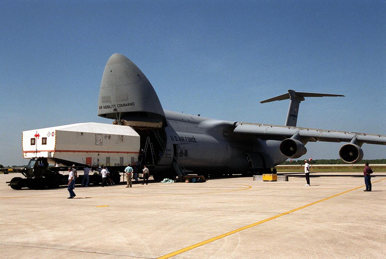
At the Shuttle Landing Facility, the crated Tracking and Data Relay Satellite (TDRS-H) is offloaded from an air cargo plane. It will be taken to the Spacecraft Assembly and Encapsulation Facility (SAEF-2) for testing. The TDRS is one of three (labeled H, I and J) being built in the Hughes Space and Communications Company Integrated Satellite Factory in El Segundo, Calif. The latest TDRS uses an innovative springback antenna design. A pair of 15-foot-diameter, flexible mesh antenna reflectors fold up for launch, then spring back into their original cupped circular shape on orbit. The new satellites will augment the TDRS system’s existing Sand Ku-band frequencies by adding Ka-band capability. TDRS will serve as the sole means of continuous, high-data-rate communication with the space shuttle, with the International Space Station upon its completion, and with dozens of unmanned scientific satellites in low earth orbit. The TDRS is scheduled to be launched from CCAFS June 29 aboard an Atlas IIA/Centaur rocket

In the Spacecraft Assembly and Encapsulation Facility, the Tracking and Data Relay Satellite (TDRS-H) at left is ready for encapsulation. Workers in an extended platform are moved closer to the fairing at right of the satellite. After encapsulation in the fairing, TDRS will be transported to Launch Pad 36A, Cape Canaveral Air Force Station for launch scheduled June 29 aboard an Atlas IIA/Centaur rocket. One of three satellites (labeled H, I and J) being built in the Hughes Space and Communications Company Integrated Satellite Factory in El Segundo, Calif., the latest TDRS uses an innovative springback antenna design. A pair of 15-foot-diameter, flexible mesh antenna reflectors fold up for launch, then spring back into their original cupped circular shape on orbit. The new satellites will augment the TDRS system’s existing Sand Ku-band frequencies by adding Ka-band capability. TDRS will serve as the sole means of continuous, high-data-rate communication with the space shuttle, with the International Space Station upon its completion, and with dozens of unmanned scientific satellites in low earth orbit
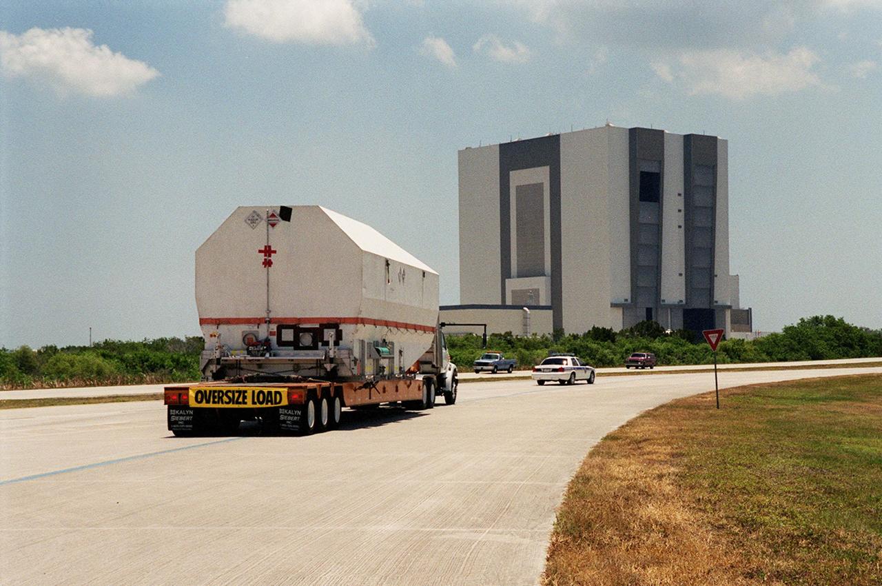
After its arrival at the Shuttle Landing Facility, the crated Tracking and Data Relay Satellite (TDRS-H) is transported past the Vehicle Assembly Building (in the background) to the Spacecraft Assembly and Encapsulation Facility (SAEF-2) for testing. The TDRS is one of three (labeled H, I and J) being built in the Hughes Space and Communications Company Integrated Satellite Factory in El Segundo, Calif. The latest TDRS uses an innovative springback antenna design. A pair of 15-foot-diameter, flexible mesh antenna reflectors fold up for launch, then spring back into their original cupped circular shape on orbit. The new satellites will augment the TDRS system’s existing Sand Ku-band frequencies by adding Ka-band capability. TDRS will serve as the sole means of continuous, high-data-rate communication with the space shuttle, with the International Space Station upon its completion, and with dozens of unmanned scientific satellites in low earth orbit. The TDRS is scheduled to be launched from CCAFS June 29 aboard an Atlas IIA/Centaur rocket
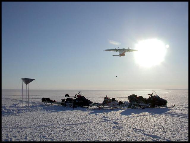
An airplane drops essential support on the Austfonna Ice Cap in Svalbard (Norwegian Arctic). The triangular structure is a corner reflector used as ground reference for airborne radar surveys. To learn about the contributions of glaciers to sea level rise, visit: <a href="http://www.nasa.gov/topics/earth/features/glacier-sea-rise.html" rel="nofollow">www.nasa.gov/topics/earth/features/glacier-sea-rise.html</a> Credit: Andrea Taurisano, Norwegian Polar Institute <b><a href="http://www.nasa.gov/audience/formedia/features/MP_Photo_Guidelines.html" rel="nofollow">NASA image use policy.</a></b> <b><a href="http://www.nasa.gov/centers/goddard/home/index.html" rel="nofollow">NASA Goddard Space Flight Center</a></b> enables NASA’s mission through four scientific endeavors: Earth Science, Heliophysics, Solar System Exploration, and Astrophysics. Goddard plays a leading role in NASA’s accomplishments by contributing compelling scientific knowledge to advance the Agency’s mission. <b>Follow us on <a href="http://twitter.com/NASA_GoddardPix" rel="nofollow">Twitter</a></b> <b>Like us on <a href="http://www.facebook.com/pages/Greenbelt-MD/NASA-Goddard/395013845897?ref=tsd" rel="nofollow">Facebook</a></b> <b>Find us on <a href="http://instagram.com/nasagoddard?vm=grid" rel="nofollow">Instagram</a></b>

MarCO-B, one of the experimental Mars Cube One (MarCO) CubeSats, took this image of Mars from about 10,900 miles (17,500 kilometers) away just after NASA’s InSight spacecraft landed on Mars on Nov. 26, 2018. MarCO-B flew by Mars with its twin, MarCO-A, to serve as communications relays for InSight as it touched down on the Red Planet around noon PST (3 p.m. EST). This image was taken at 1 p.m. PST (4 p.m. EST). A crescent Mars with its south pole in the 4 o’clock position is visible in this picture. MarCO-B’s antenna reflector mirrors a portion of the illuminated part of Mars on the bottom right. The antenna feed (white rectangle with gold squares) is visible on the left. This image was taken about 50 minutes after PIA22833 and 10 seconds after PIA22832. The MarCO and InSight projects are managed for NASA's Science Mission Directorate, Washington, by JPL, a division of Caltech, Pasadena. Credit: NASA/JPL-Caltech
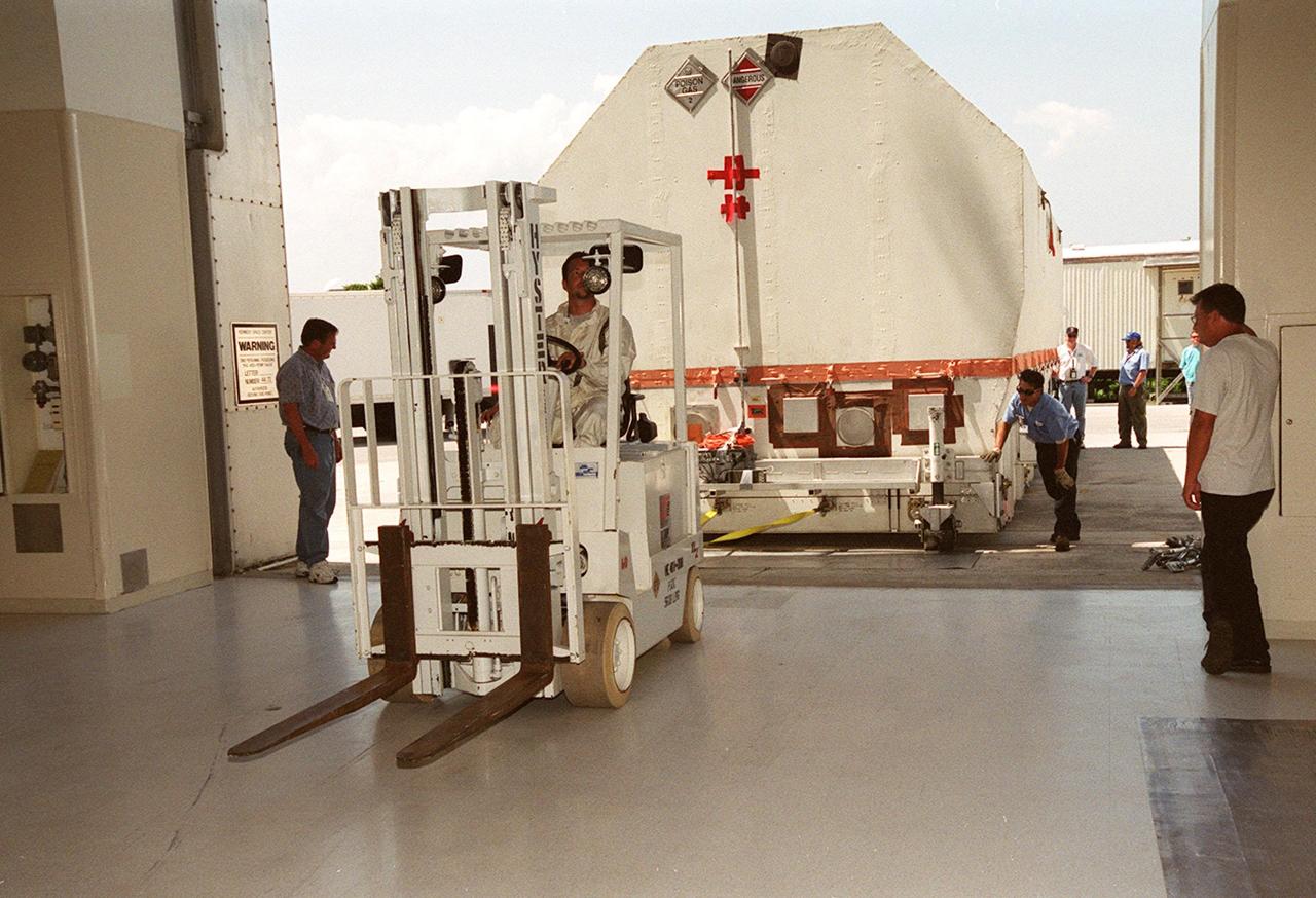
The crated Tracking and Data Relay Satellite (TDRS-H) is pulled inside the Spacecraft Assembly and Encapsulation Facility (SAEF-2) after its arrival at KSC. The TDRS will undergo testing in the SAEF-2. One of three satellites (labeled H, I and J) being built in the Hughes Space and Communications Company Integrated Satellite Factory in El Segundo, Calif., the latest TDRS uses an innovative springback antenna design. A pair of 15-foot-diameter, flexible mesh antenna reflectors fold up for launch, then spring back into their original cupped circular shape on orbit. The new satellites will augment the TDRS system’s existing Sand Ku-band frequencies by adding Ka-band capability. TDRS will serve as the sole means of continuous, high-data-rate communication with the space shuttle, with the International Space Station upon its completion, and with dozens of unmanned scientific satellites in low earth orbit. The TDRS is scheduled to be launched from CCAFS June 29 aboard an Atlas IIA/Centaur rocket
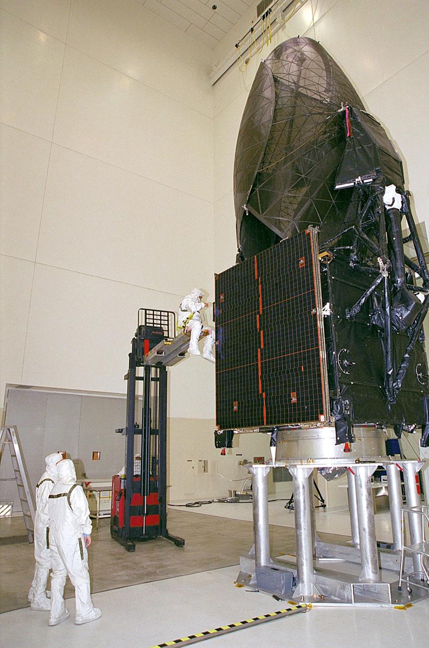
In the Spacecraft Assembly and Encapsulation Facility, a worker (left center) checks out the Tracking and Data Relay Satellite (TDRS-H) after its move to the payload adapter (below). Next step is the encapsulation of the TDRS in the fairing. TDRS is scheduled to be launched June 29 aboard an Atlas IIA/Centaur rocket. One of three satellites (labeled H, I and J) being built in the Hughes Space and Communications Company Integrated Satellite Factory in El Segundo, Calif., the latest TDRS uses an innovative springback antenna design. A pair of 15-foot-diameter, flexible mesh antenna reflectors fold up for launch, then spring back into their original cupped circular shape on orbit. The new satellites will augment the TDRS system’s existing Sand Ku-band frequencies by adding Ka-band capability. TDRS will serve as the sole means of continuous, high-data-rate communication with the space shuttle, with the International Space Station upon its completion, and with dozens of unmanned scientific satellites in low earth orbit

The logo for the Tracking and Data Relay Satellite (TDRS-H) is predominantly displayed on the fairing that will encapsulate the satellite for launch. The fairing is in KSC’s Spacecraft Assembly and Encapsulation Facility (SAEF-2) where TDRS is undergoing testing. The TDRS is scheduled to be launched from CCAFS June 29 aboard an Atlas IIA/Centaur rocket. One of three satellites (labeled H, I and J) being built in the Hughes Space and Communications Company Integrated Satellite Factory in El Segundo, Calif., the latest TDRS uses an innovative springback antenna design. A pair of 15-foot-diameter, flexible mesh antenna reflectors fold up for launch, then spring back into their original cupped circular shape on orbit. The new satellites will augment the TDRS system’s existing Sand Ku-band frequencies by adding Ka-band capability. TDRS will serve as the sole means of continuous, high-data-rate communication with the space shuttle, with the International Space Station upon its completion, and with dozens of unmanned scientific satellites in low earth orbit

KENNEDY SPACE CENTER, FLA. -- The container with the Microwave Anisotropy Probe (MAP) satellite inside moves into the Spacecraft Assembly and Encapsulation Facility 2. MAP will undergo testing in the SAEF-2 before its scheduled launch June 30 from Cape Canaveral Air Force Station on a Delta II rocket into a lunar-assisted trajectory to the Sun-Earth for a 27-month mission (3 months transit, 24 months observing). The MAP instrument consists of a set of passively cooled microwave radiometers with 1.4x 1.6-meter diameter primary reflectors to provide the desired angular resolution. MAP measures small fluctuations in the temperature of the cosmic microwave background radiation to an accuracy of one millionth of a degree. These measurements should reveal the size, matter content, age, geometry and fate of the universe. They will also reveal the primordial structure that grew to form galaxies and will test ideas about the origins of these primordial structures. The MAP instrument will be continuously shaded from the Sun, Earth, and Moon by the spacecraft. It is a product of Goddard Space Flight Center in partnership with Princeton University

In the Spacecraft Assembly and Encapsulation Facility, the Tracking and Data Relay Satellite (TDRS-H) at left is ready for encapsulation. Workers in an extendable platform wait for the fairing (right) to move into place. After encapsulation in the fairing, TDRS will be transported to Launch Pad 36A, Cape Canaveral Air Force Station for launch scheduled June 29 aboard an Atlas IIA/Centaur rocket. One of three satellites (labeled H, I and J) being built in the Hughes Space and Communications Company Integrated Satellite Factory in El Segundo, Calif., the latest TDRS uses an innovative springback antenna design. A pair of 15-foot-diameter, flexible mesh antenna reflectors fold up for launch, then spring back into their original cupped circular shape on orbit. The new satellites will augment the TDRS system’s existing Sand Ku-band frequencies by adding Ka-band capability. TDRS will serve as the sole means of continuous, high-data-rate communication with the space shuttle, with the International Space Station upon its completion, and with dozens of unmanned scientific satellites in low earth orbit
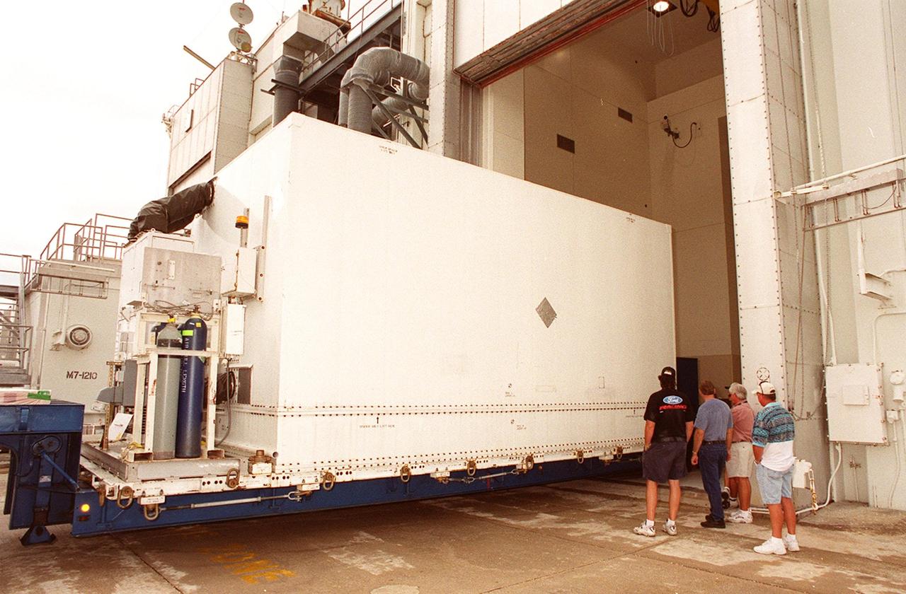
KENNEDY SPACE CENTER, FLA. -- The container with the Microwave Anisotropy Probe (MAP) satellite inside is backed into the Spacecraft Assembly and Encapsulation Facility 2. MAP will undergo testing in the SAEF-2 before its scheduled launch June 30 from Cape Canaveral Air Force Station on a Delta II rocket into a lunar-assisted trajectory to the Sun-Earth for a 27-month mission (3 months transit, 24 months observing). The MAP instrument consists of a set of passively cooled microwave radiometers with 1.4x 1.6-meter diameter primary reflectors to provide the desired angular resolution. MAP measures small fluctuations in the temperature of the cosmic microwave background radiation to an accuracy of one millionth of a degree. These measurements should reveal the size, matter content, age, geometry and fate of the universe. They will also reveal the primordial structure that grew to form galaxies and will test ideas about the origins of these primordial structures. The MAP instrument will be continuously shaded from the Sun, Earth, and Moon by the spacecraft. It is a product of Goddard Space Flight Center in partnership with Princeton University
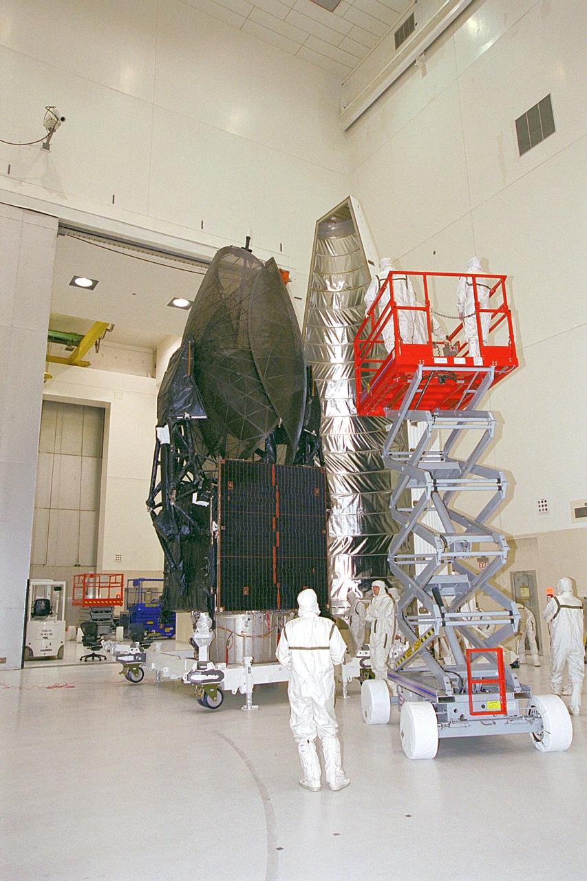
In the Spacecraft Assembly and Encapsulation Facility, the Tracking and Data Relay Satellite (TDRS-H) at left is ready for encapsulation. Workers in an extended platform are moved closer to the fairing at right of the satellite. After encapsulation in the fairing, TDRS will be transported to Launch Pad 36A, Cape Canaveral Air Force Station for launch scheduled June 29 aboard an Atlas IIA/Centaur rocket. One of three satellites (labeled H, I and J) being built in the Hughes Space and Communications Company Integrated Satellite Factory in El Segundo, Calif., the latest TDRS uses an innovative springback antenna design. A pair of 15-foot-diameter, flexible mesh antenna reflectors fold up for launch, then spring back into their original cupped circular shape on orbit. The new satellites will augment the TDRS system’s existing Sand Ku-band frequencies by adding Ka-band capability. TDRS will serve as the sole means of continuous, high-data-rate communication with the space shuttle, with the International Space Station upon its completion, and with dozens of unmanned scientific satellites in low earth orbit
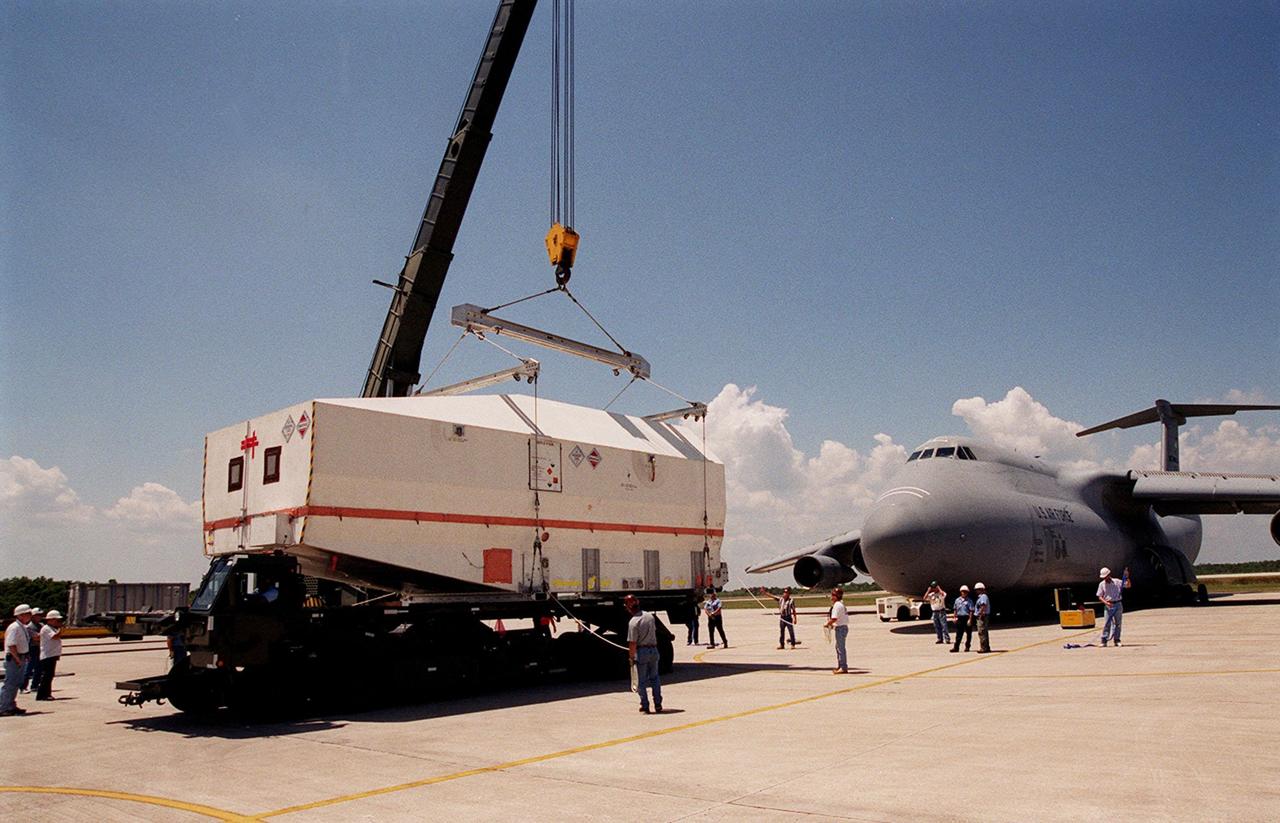
At the Shuttle Landing Facility, the crated Tracking and Data Relay Satellite (TDRS-H) is placed onto a transporter for its move to the Spacecraft Assembly and Encapsulation Facility (SAEF-2) for testing. The TDRS is one of three (labeled H, I and J) being built in the Hughes Space and Communications Company Integrated Satellite Factory in El Segundo, Calif. The latest TDRS uses an innovative springback antenna design. A pair of 15-foot-diameter, flexible mesh antenna reflectors fold up for launch, then spring back into their original cupped circular shape on orbit. The new satellites will augment the TDRS system’s existing Sand Ku-band frequencies by adding Ka-band capability. TDRS will serve as the sole means of continuous, high-data-rate communication with the space shuttle, with the International Space Station upon its completion, and with dozens of unmanned scientific satellites in low earth orbit. The TDRS is scheduled to be launched from CCAFS June 29 aboard an Atlas IIA/Centaur rocket