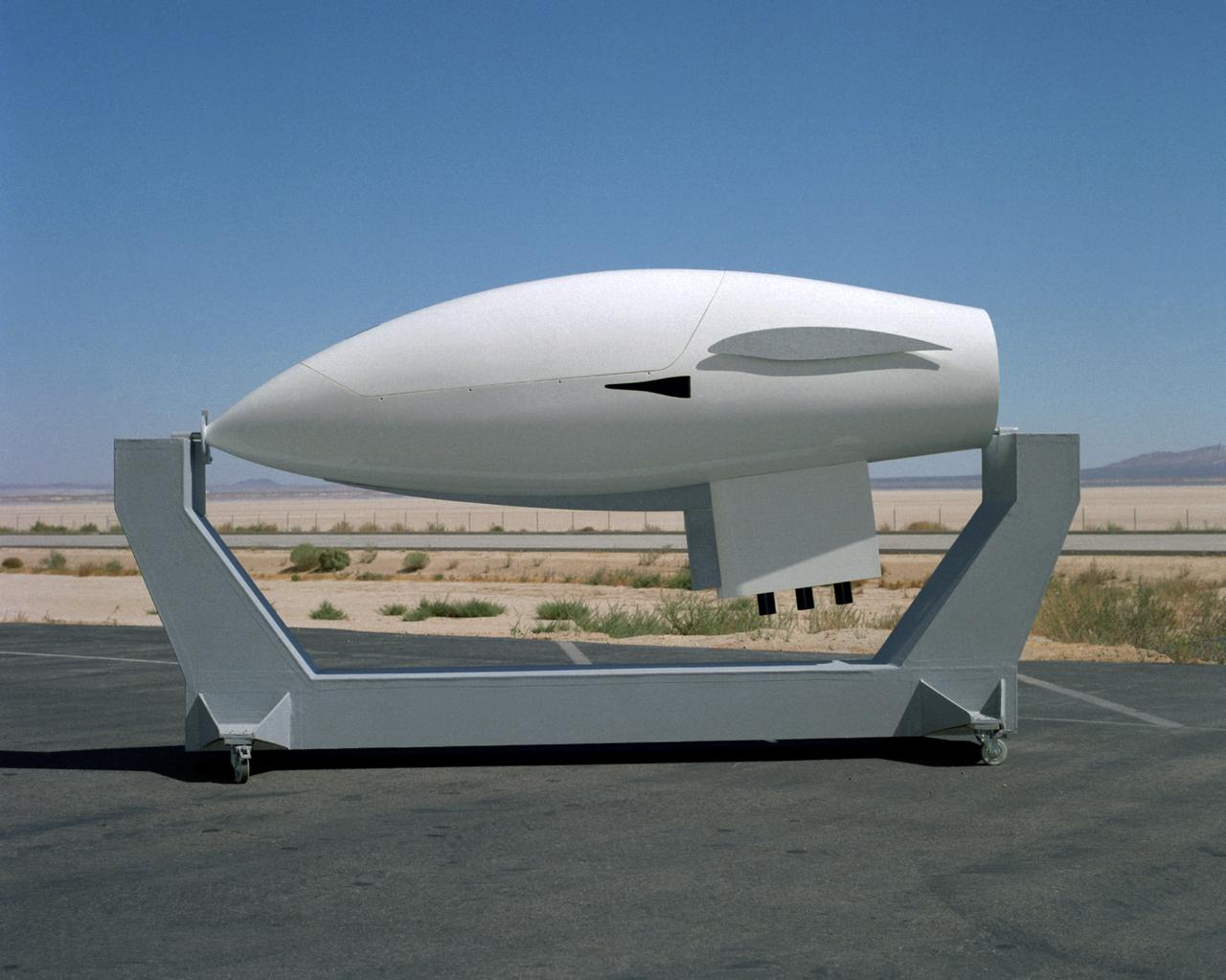
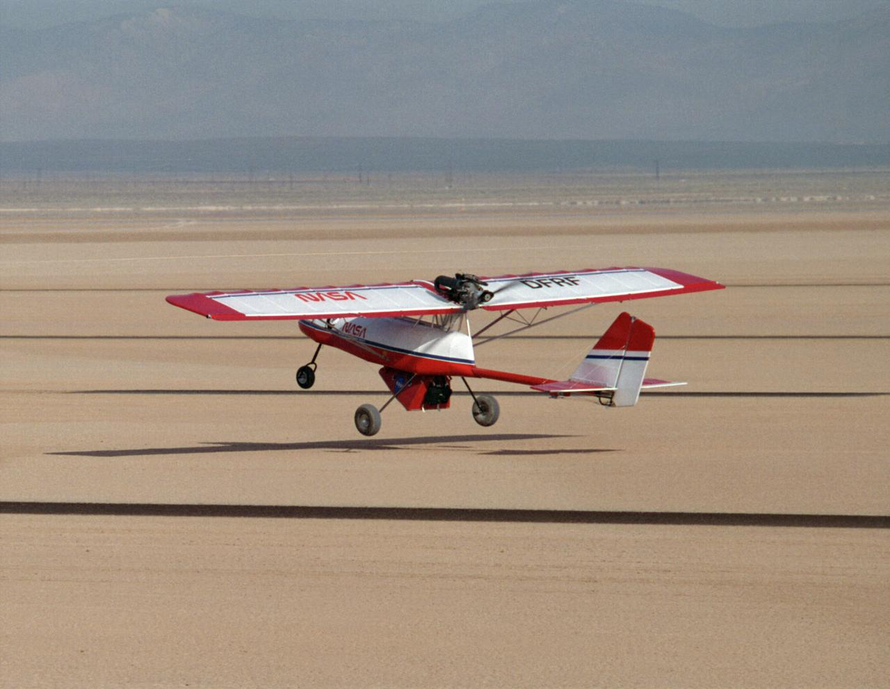
The Hyper III was a full-scale lifting-body remotely piloted research vehicle (RPRV) built at what was then the NASA Flight Research Center located at Edwards Air Force Base in Southern California.
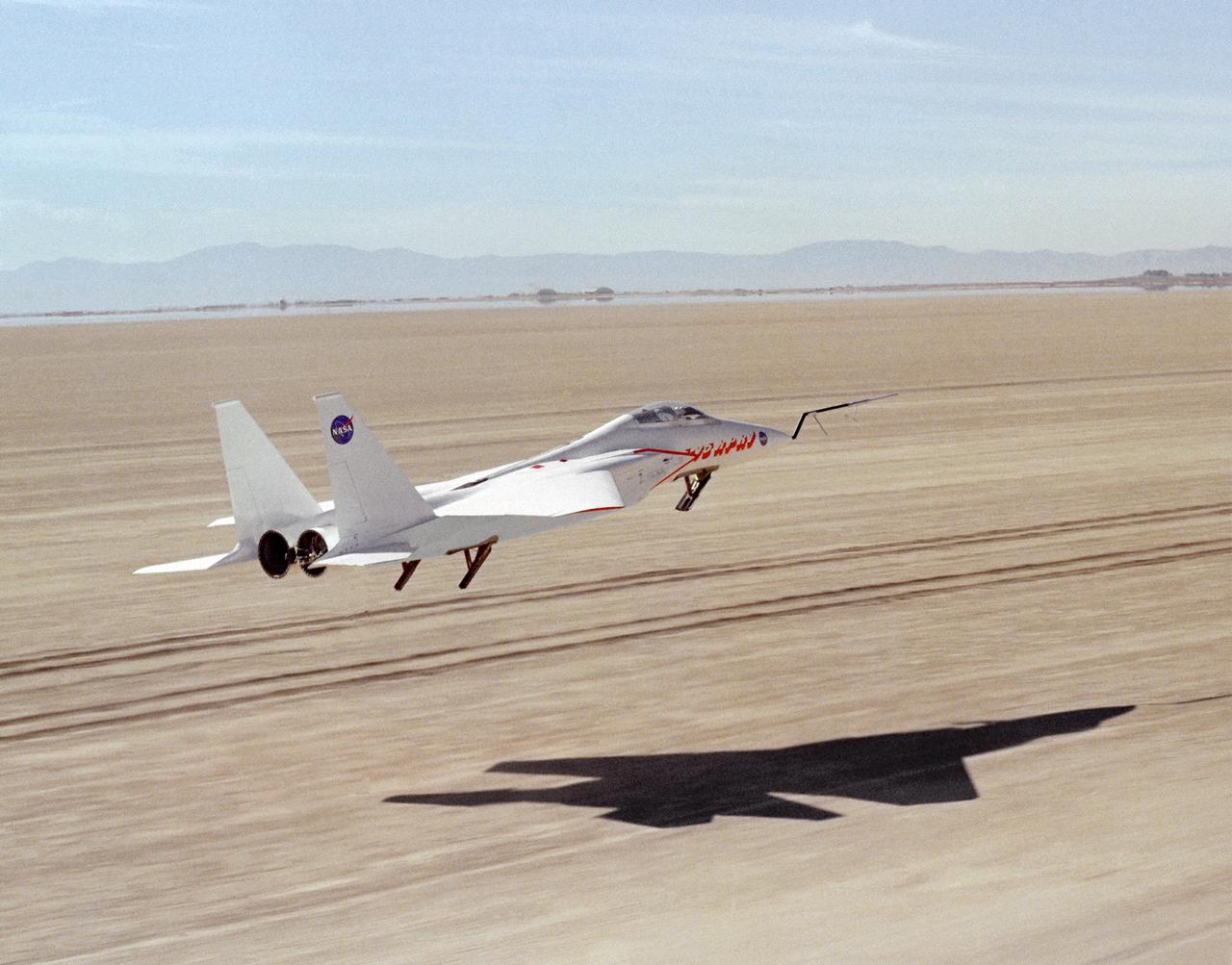
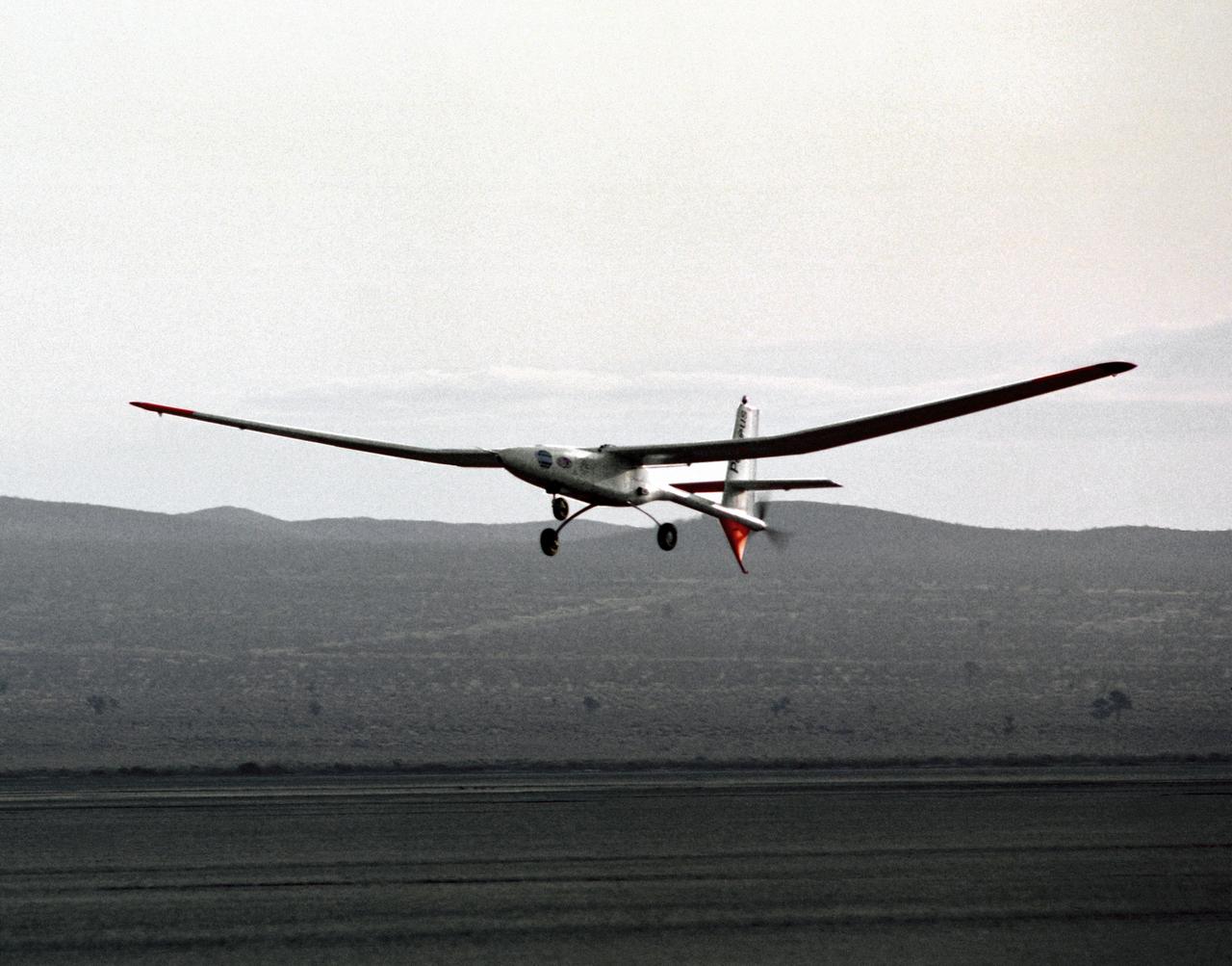
This photograph shows NASA's 3/8th-scale remotely piloted research vehicle landing on Rogers Dry Lakebed at Edwards Air Force Base, California, in 1975.
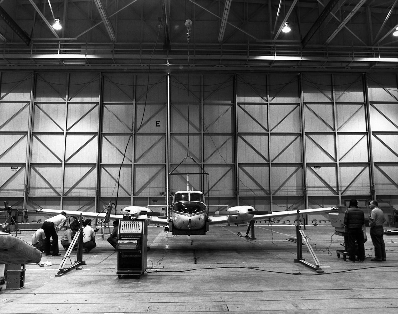
Technicians check instrumentation and systems on NASA 808, a PA-30 aircraft, prior to a research flight. The aircraft was used as the testbed in development of control systems for remotely piloted vehicles that were "flown" from the ground. The concept led to highly successful programs such as the HiMAT and the subscale F-15 remotely piloted vehicles. Over the years, NASA 808 has also been used for spin and stall research related to general aviation aircraft and also research to alleviate wake vortices behind large jetliners. This 1980 photograph taken inside a hangar shows technicians measuring moment of inertia.
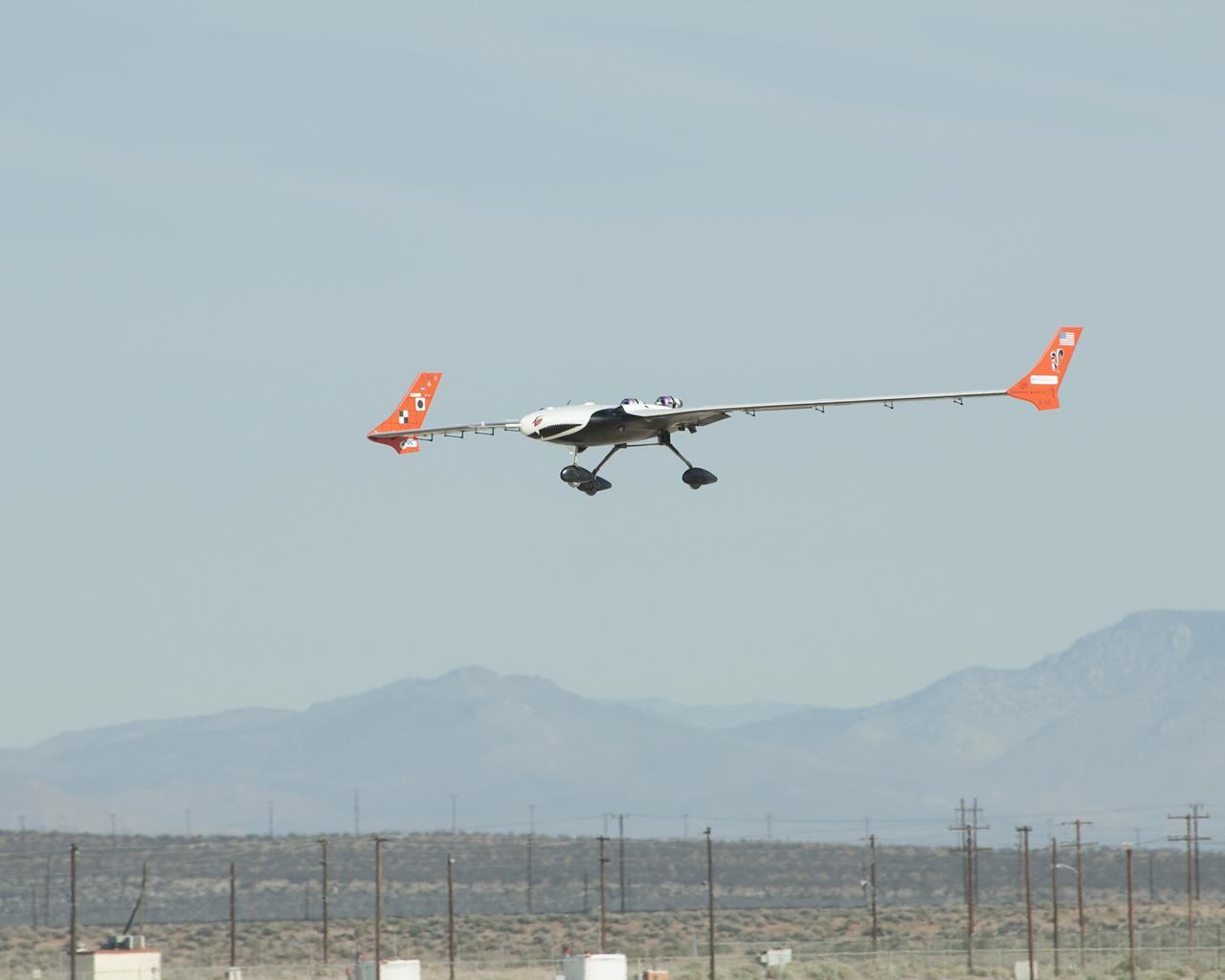
NASA researchers are using the X-56A, a low-cost, modular, remotely piloted aerial vehicle, to explore the behavior of lightweight, flexible aircraft structures.
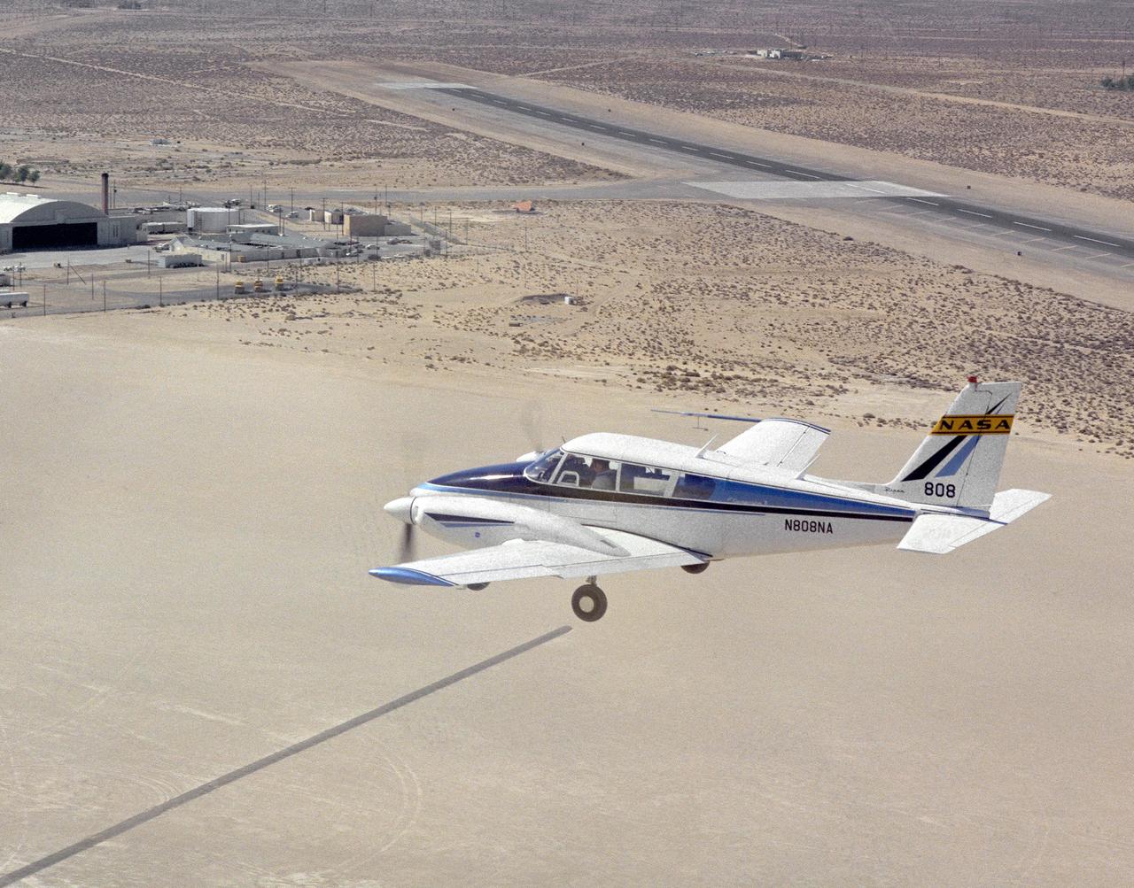
Dryden Flight Research Center's Piper PA-30 Twin Commanche, which helped validate the RPRV concept, descends to a remotely controlled landing on Rogers Dry Lake, unassisted by the onboard pilot. A Piper PA-30 Twin Commanche, known as NASA 808, was used at the NASA Dryden Flight Research Center as a rugged workhorse in a variety of research projects associated with both general aviation and military projects. In the early 1970s, the PA-30, serial number 301498, was used to test a flight technique used to fly Remotely Piloted Research Vehicles (RPRV's). The technique was first tested with the cockpit windows of the light aircraft blacked out while the pilot flew the aircraft utilizing a television monitor which gave him a "pilot's eye" view ahead of the aircraft. Later pilots flew the aircraft from a ground cockpit, a procedure used with all RPRV's. TV and two-way telemetry allow the pilot to be in constant control of the aircraft. The apparatus mounted over the cockpit is a special fish eye lens camera, used to obtain images that are transmitted to the ground based cockpit. This project paved the way for sophisticated, highly successful research programs involving high risk spin, stall, and flight control conditions, such as the HiMAT and the subscale F-15 remotely piloted vehicles. Over the years, NASA 808 has also been used for spin and stall research related to general aviation aircraft and also research to alleviate wake vortices behind large jetliners.
The Hyper III was a low-cost test vehicle for an advanced lifting-body shape. Like the earlier M2-F1, it was a "homebuilt" research aircraft, i.e., built at the Flight Research Center (FRC), later redesignated the Dryden Flight Research Center. It had a steel-tube frame covered with Dacron, a fiberglass nose, sheet aluminum fins, and a wing from an HP-11 sailplane. Construction was by volunteers at the FRC. Although the Hyper III was to be flown remotely in its initial tests, it was fitted with a cockpit for a pilot. On the Hyper III's only flight, it was towed aloft attached to a Navy SH-3 helicopter by a 400-foot cable. NASA research pilot Bruce Peterson flew the SH-3. After he released the Hyper III from the cable, NASA research pilot Milt Thompson flew the vehicle by radio control until the final approach when Dick Fischer took over control using a model-airplane radio-control box. The Hyper III flared, then landed and slid to a stop on Rogers Dry Lakebed.
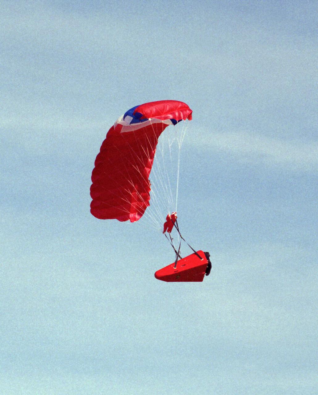
One of the Spacewedge remotely-piloted research vehicles in flight under a steerable parafoil during 1995 research flights conducted by NASA’s Dryden Flight Research Center.
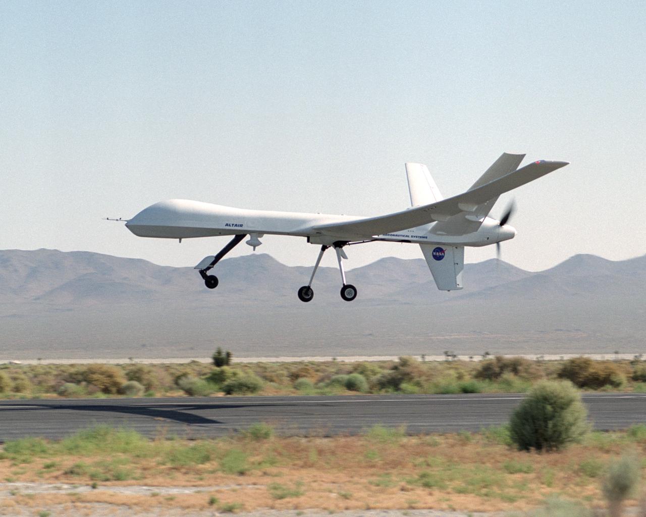
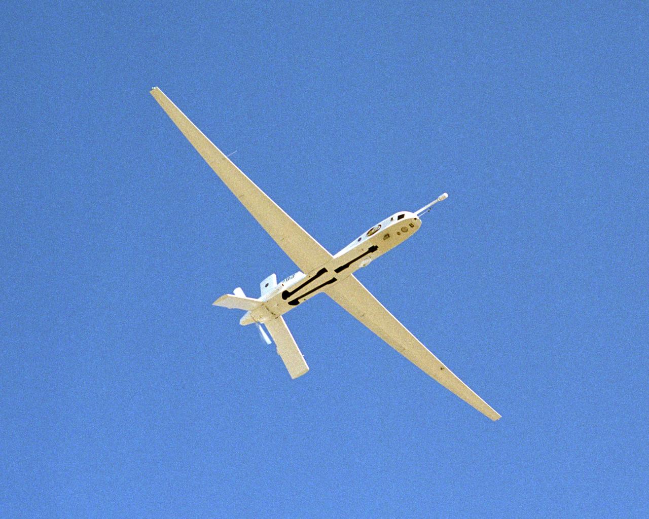
The remotely-piloted Altair unmanned aerial vehicle (UAV) took to the air on its first checkout flight on June 9, 2003 at El Mirage, California.
The Perseus proof-of-concept vehicle flies over Rogers Dry Lake at the Dryden Flight Research Center, Edwards, California, to test basic design concepts for the remotely-piloted, high-altitude vehicle.
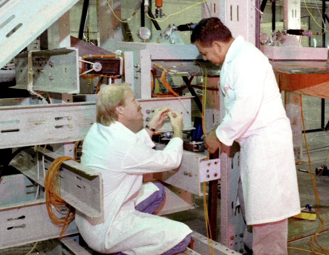
Apex wing section undergoing loading test preparation by Mark Nunnelee and Eliseo Sanchez
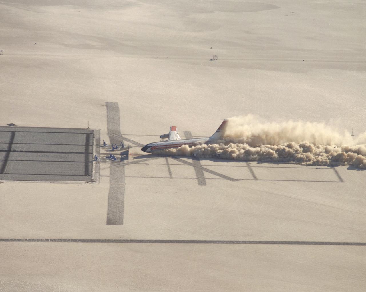
CID (Controlled Imact Demonstrator) Aircraft skid after wing cutter impact.
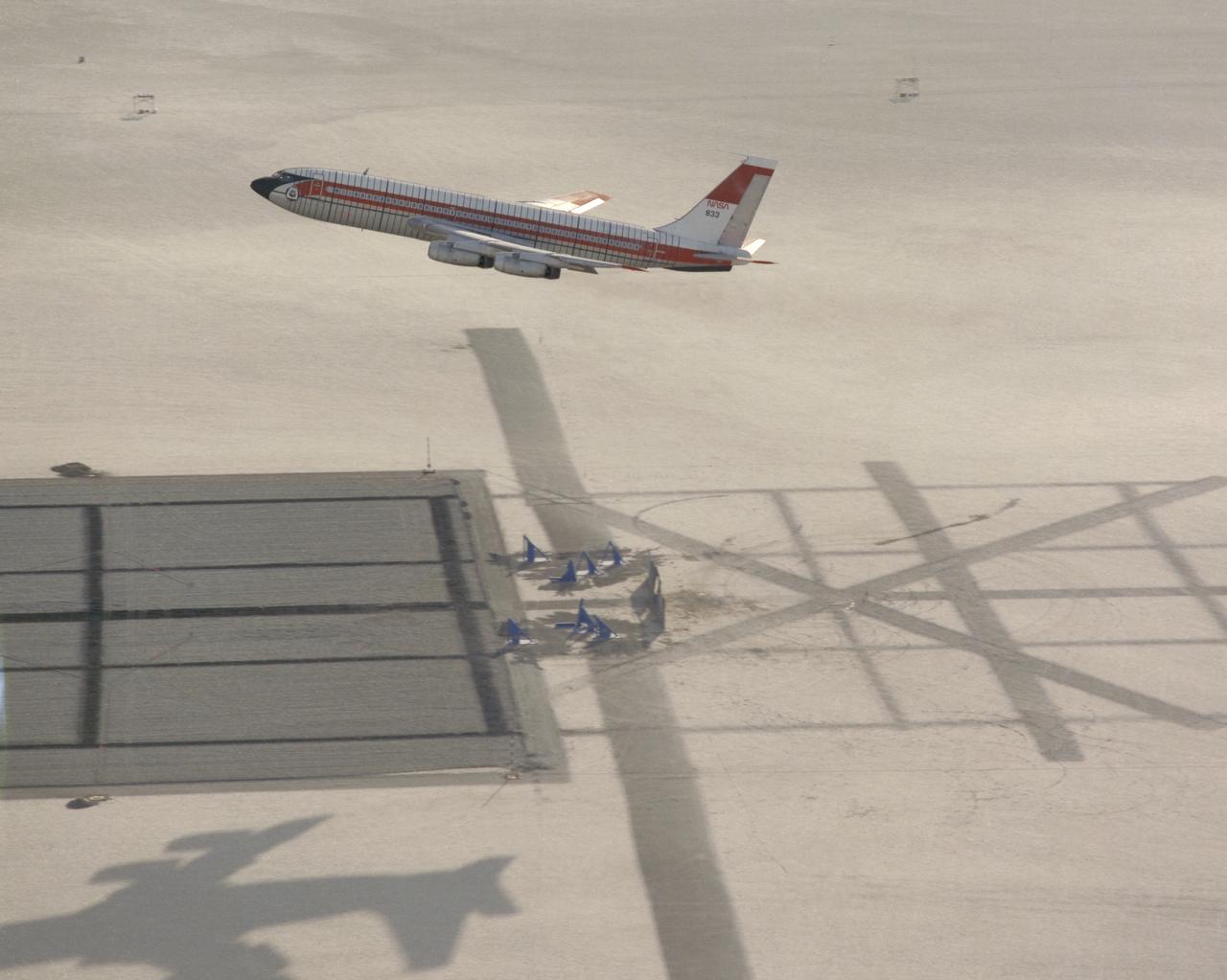
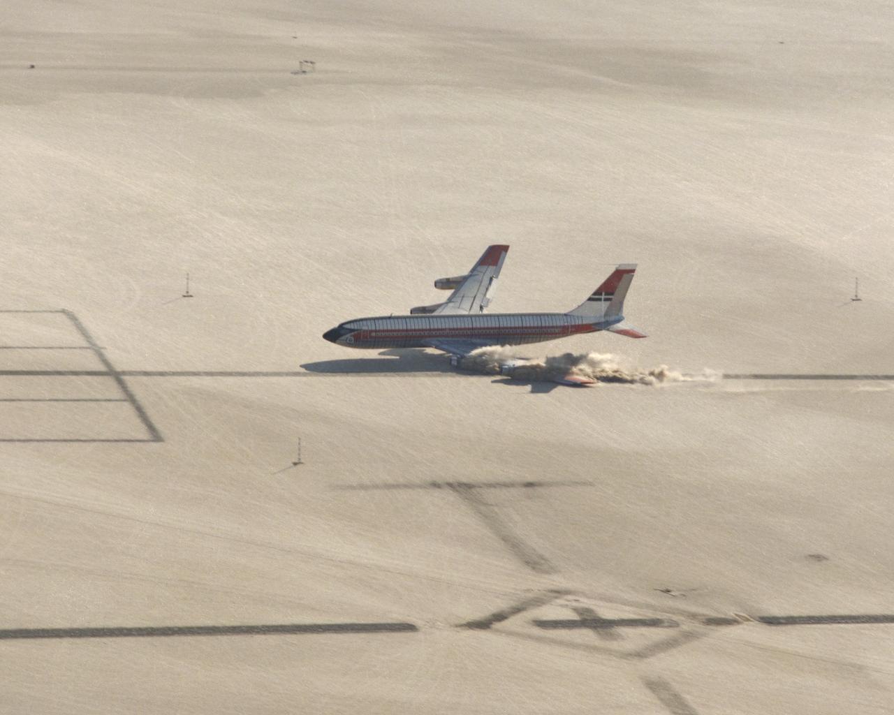
CID (Controlled Imact Demonstrator) Aircraft in practice flight above target impact site with wing cutters.
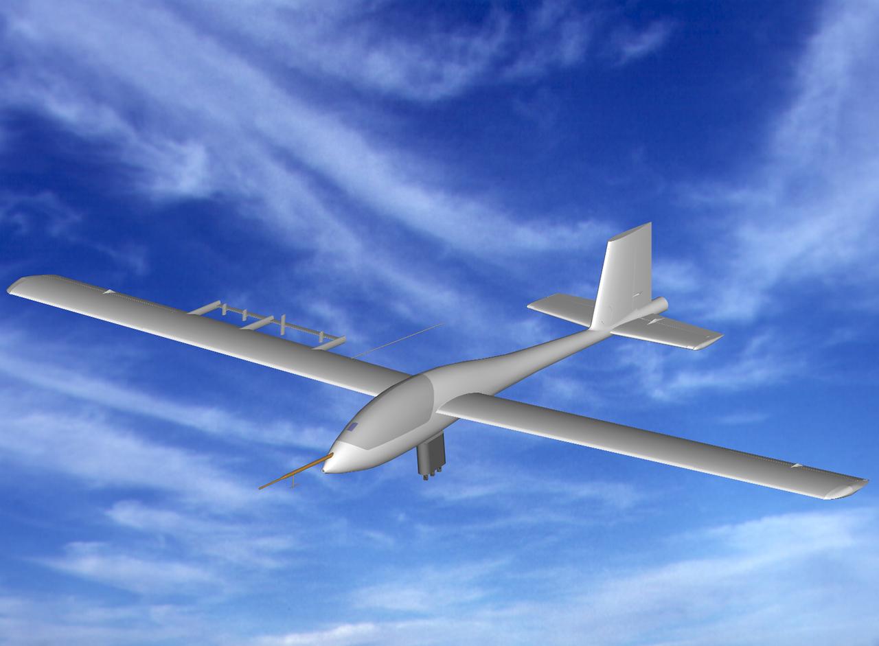
Computer generated image of Apex high-altitude research sailplane in flight
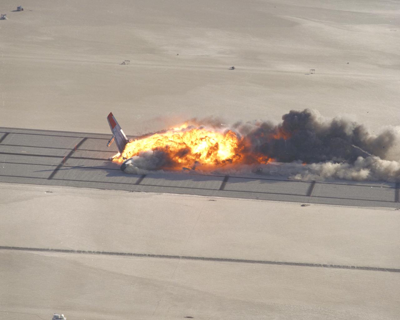
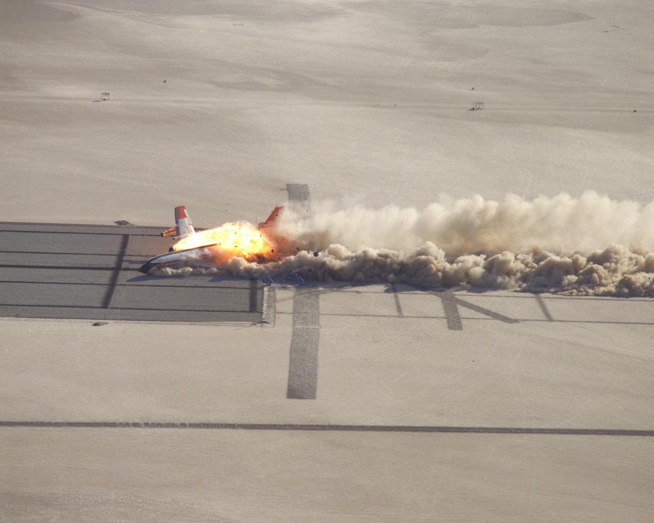
CID (Controlled Imact Demonstrator) Aircraft fireball after wing cutter impact.
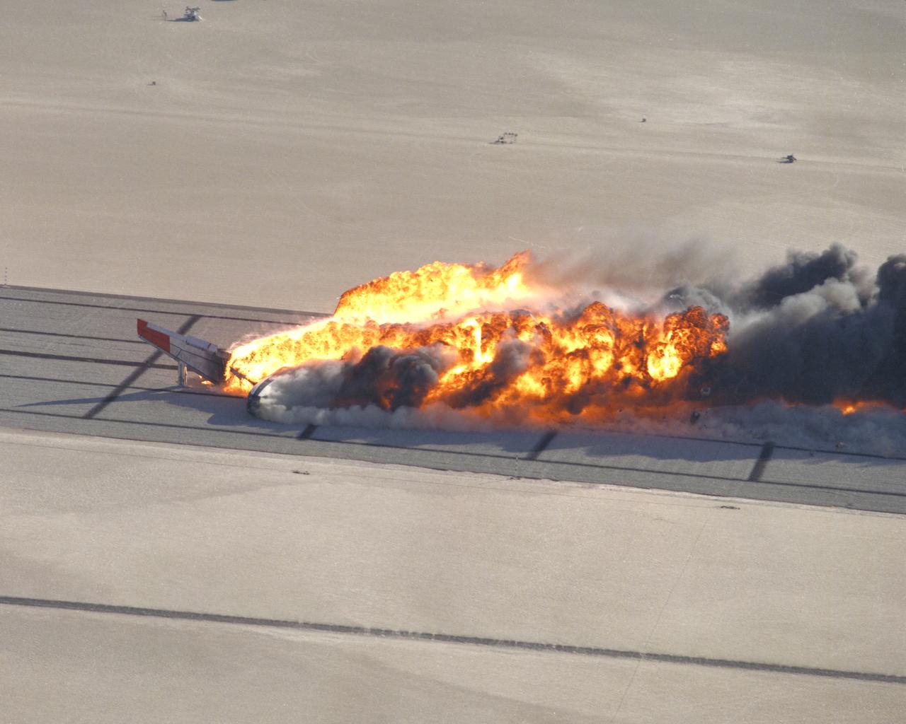
CID (Controlled Imact Demonstrator) Aircraft fireball after wing cutter impact.
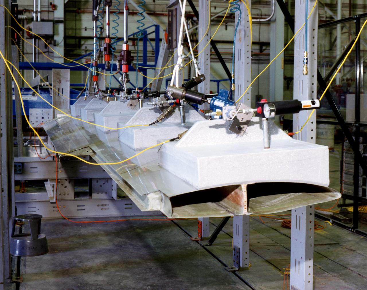
Apex wing section undergoing loading test.
Apex high-altitude research sailplane mock-up
CID (Controlled Imact Demonstrator) Aircraft lakebed skid.
CID (Controlled Imact Demonstrator) Aircraft prior to wing cutter impact during lakebed skid.
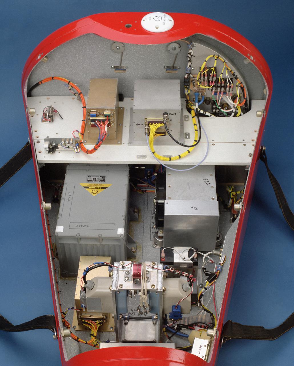
This photo shows the instrumentation and equipment inside the Spacewedge #3, a remotely-piloted research vehicle flown at the Dryden Flight Research Center, Edwards, California, to help develop technology for autonomous return systems for spacecraft as well as methods to deliver large Army cargo payloads to precise landings.
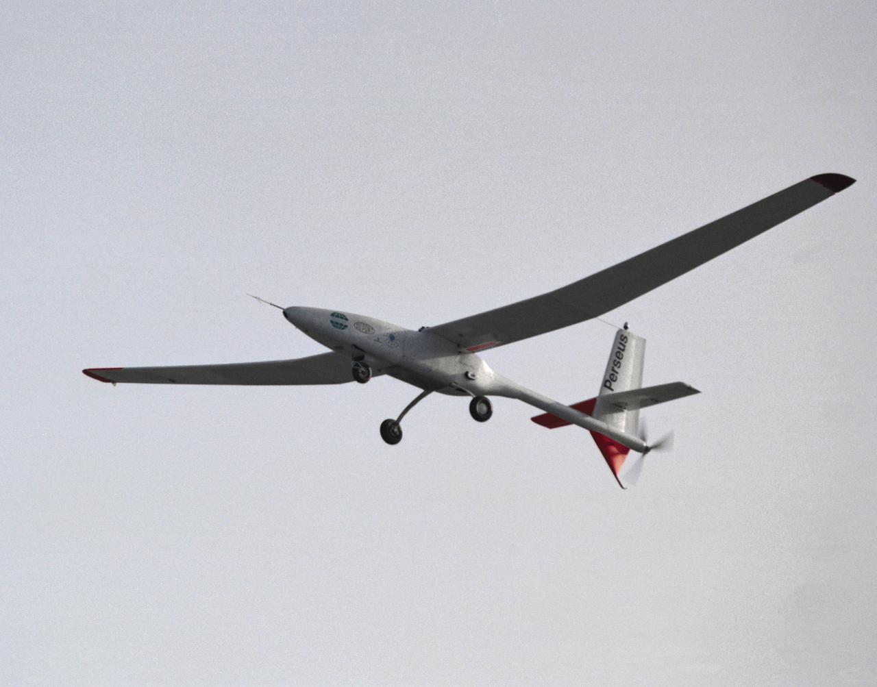
The Perseus proof-of-concept vehicle in flight at the Dryden Flight Research Center, Edwards, California in 1991. Perseus is one of several remotely-piloted aircraft designed for high-altitude, long-endurance scientific sampling missions being evaluated under the ERAST program.
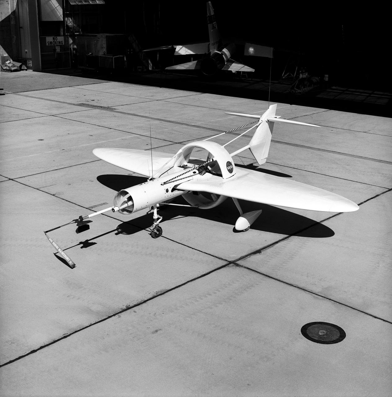
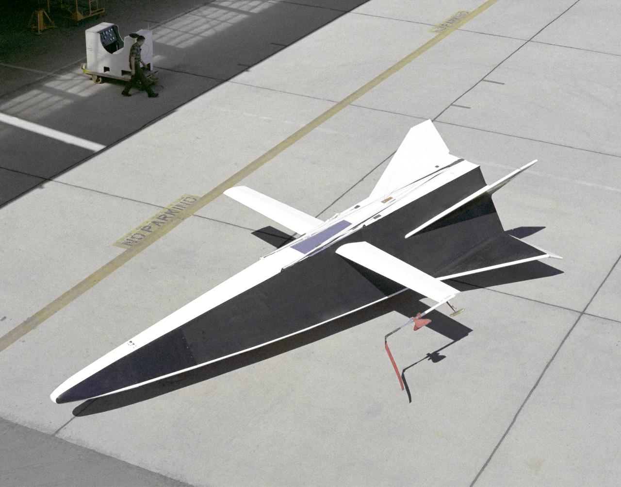
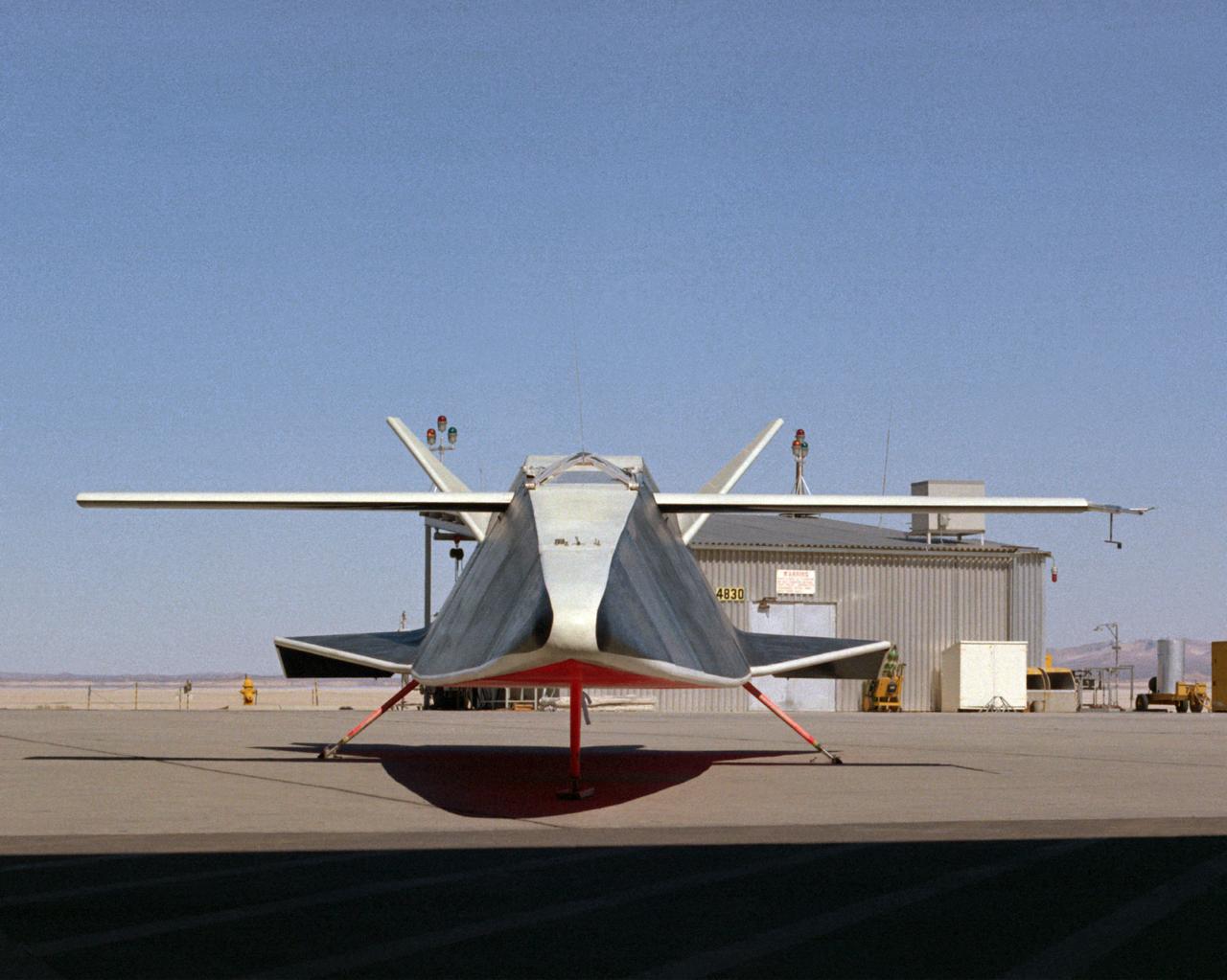
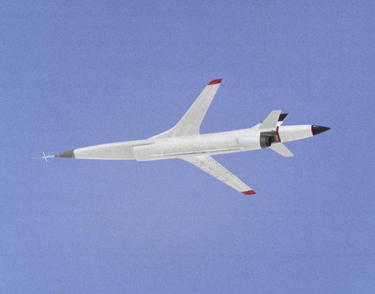
This 1976 photograph of the Oblique Wing Research Aircraft was taken in front of the NASA Flight Research Center hangar, located at Edwards Air Force Base, California. In the photograph the noseboom, pitot-static probe, and angles-of-attack and sideslip flow vanes(covered-up) are attached to the front of the vehicle. The clear nose dome for the television camera, and the shrouded propellor for the 90 horsepower engine are clearly seen.

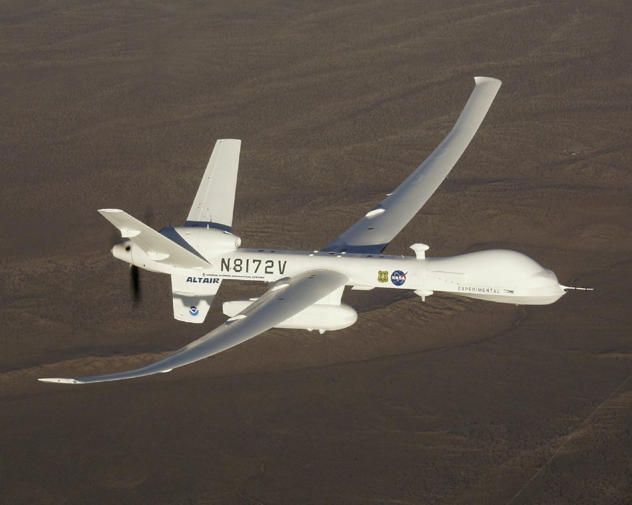
The long wings of General Atomics Altair UAV are in evidence during a series of environmental monitoring missions for NOAA and NASA in the spring of 2005.
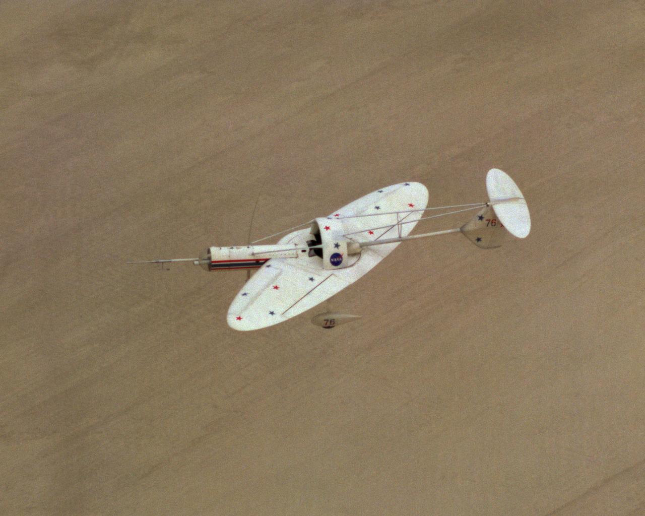
Oblique Wing Research Aircraft in flight
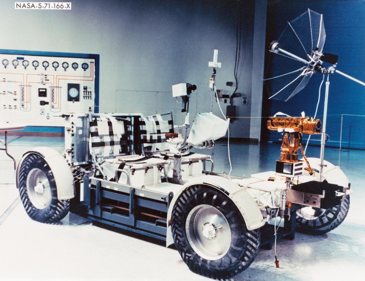
S71-00166 (June 1971) --- A close-up view of the Lunar Roving Vehicle (LRV). Apollo 15 will be the first mission to employ the services of the LRV. Astronauts David R. Scott, commander; and James B. Irwin, lunar module pilot, will move about the lunar surface in the Hadley-Apennine region in their four-wheeled vehicle while astronaut Alfred M. Worden, command module pilot, remains with the Command and Service Modules (CSM) in lunar orbit. A television camera, which can be controlled remotely from the ground (front), and a motion picture camera (rear) are among the gear on the LRV.
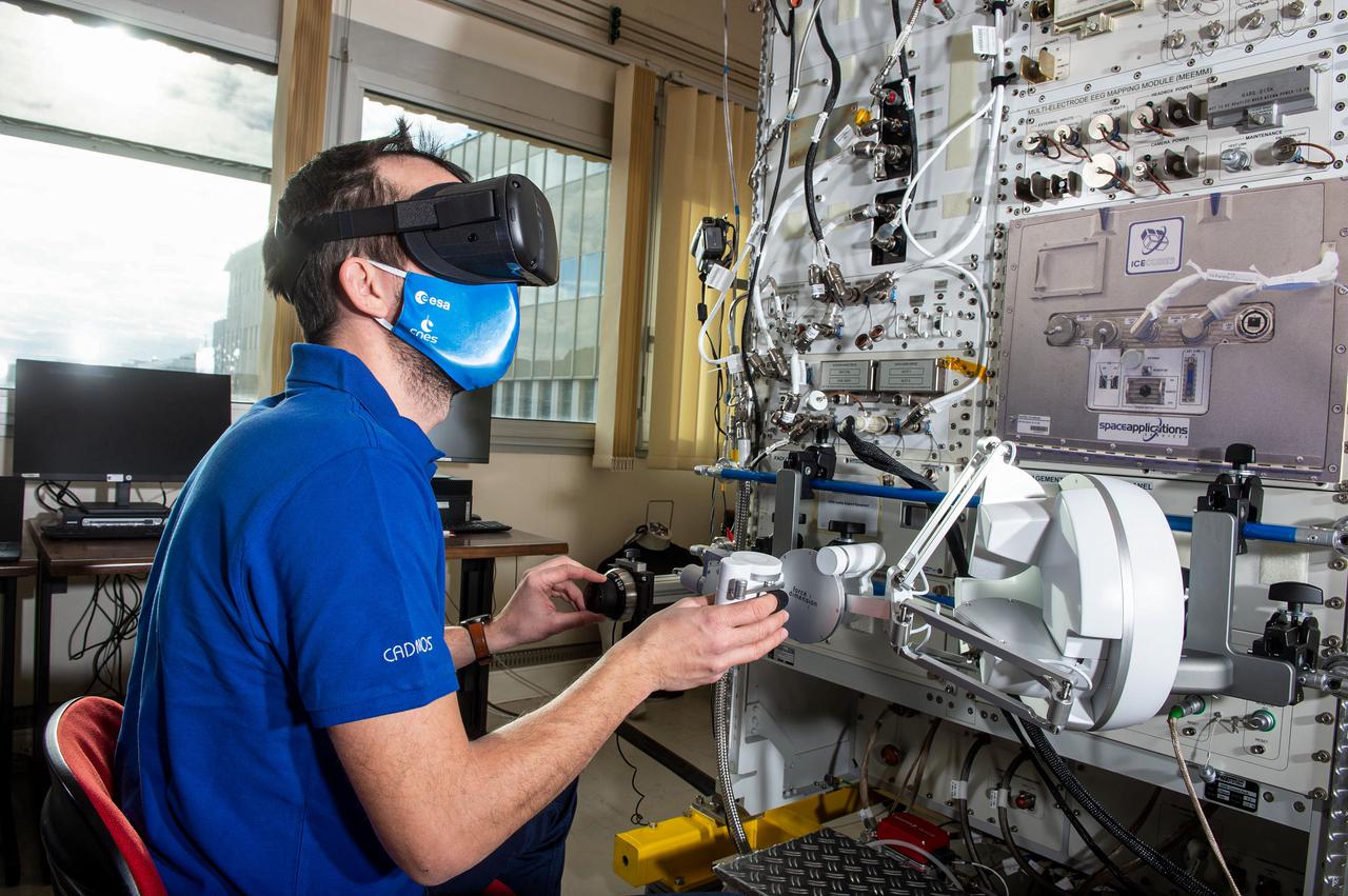
jsc2021e019399 (1/12/2021) --- Simulation of the Pilote experiment. In order to test the ergonomics of a multisensory interface for controlling robotic arms and spacecraft, it is necessary to perform the trials in microgravity. Performing the test on Earth would lead to a design of a work station using terrestrial ergonomic principles that do not correspond to conditions experienced on a spacecraft in orbit. The Pilote investigation tests the effectiveness of novel control schemes for the remote operation of robotic arms and space vehicles, using virtual reality and a new class of user-machine interfaces based on haptics. Image courtesy of CNES/GRIMAULT Emmanuel.

jsc2021e019401 (1/19/2021) --- A preflight macro shot of SIGMA-7 interface for Pilote experiment, In order to test the ergonomics of a multisensory interface for controlling robotic arms and spacecraft, it is necessary to perform the trials in microgravity. Performing the test on Earth would lead to a design of a work station using terrestrial ergonomic principles that do not correspond to conditions experienced on a spacecraft in orbit. The Pilote investigation tests the effectiveness of novel control schemes for the remote operation of robotic arms and space vehicles, using virtual reality and a new class of user-machine interfaces based on haptics. Image courtesy of CNES/DE PRADA Thierry.
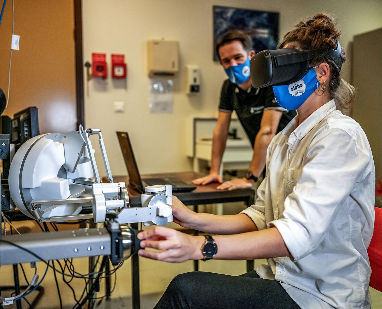
jsc2021e019398 (12/9/2020) --- Simulation of the Pilote experiment. In order to test the ergonomics of a multisensory interface for controlling robotic arms and spacecraft, it is necessary to perform the trials in microgravity. Performing the test on Earth would lead to a design of a work station using terrestrial ergonomic principles that do not correspond to conditions experienced on a spacecraft in orbit. The Pilote investigation tests the effectiveness of novel control schemes for the remote operation of robotic arms and space vehicles, using virtual reality and a new class of user-machine interfaces based on haptics. Image courtesy of CNES/DE PRADA Thierry.
jsc2021e019400 (1/12/2021) --- Simulation of the Pilote experiment. In order to test the ergonomics of a multisensory interface for controlling robotic arms and spacecraft, it is necessary to perform the trials in microgravity. Performing the test on Earth would lead to a design of a work station using terrestrial ergonomic principles that do not correspond to conditions experienced on a spacecraft in orbit. The Pilote investigation tests the effectiveness of novel control schemes for the remote operation of robotic arms and space vehicles, using virtual reality and a new class of user-machine interfaces based on haptics. Image courtesy of CNES/GRIMAULT Emmanuel.

NASA pilot Ed Lewis with the T-34C aircraft on the Dryden Flight Research Center Ramp. The aircraft was previously used at the Lewis Research Center in propulsion experiments involving turboprop engines, and was used as a chase aircraft at Dryden for smaller and slower research projects. Chase aircraft accompany research flights for photography and video purposes, and also as support for safety and research. At Dryden, the T-34 is used mainly for smaller remotely piloted vehicles which fly slower than NASA's F-18's, used for larger scale projects. This aircraft was returned to the U.S. Navy in May of 2002.
A Rans S-12 remotely piloted "mothership" takes off from a lakebed runway carrying a Spacewedge research model during 1992 flight tests. The Spacewedge was lauched in flight from the Rans S-12 aircraft and then glided back to a landing under a steerable parafoil. Technology tested in the Spacewedge program was used in developing the X-38 research vehicle.
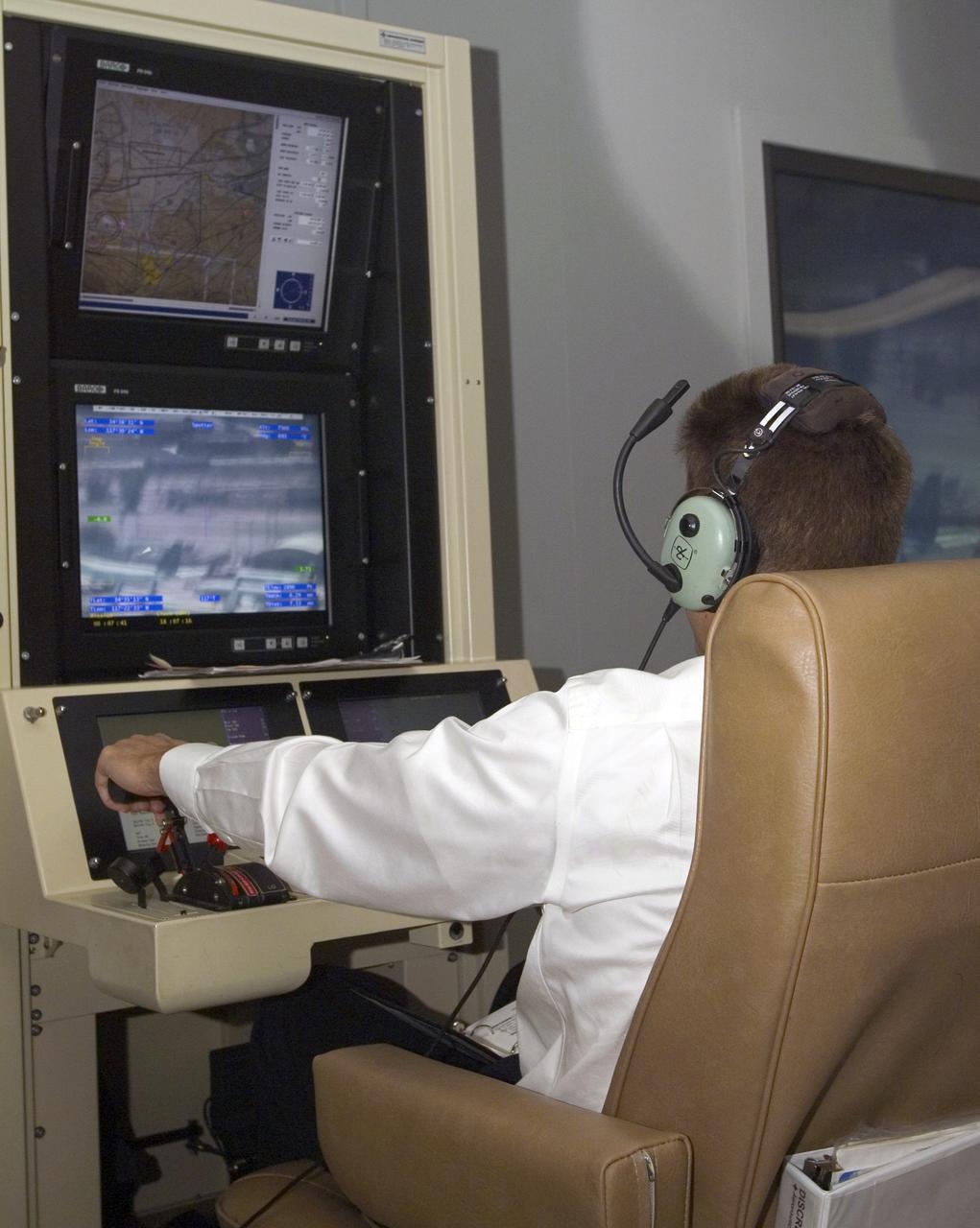
A pilot for General Atomics guides the Altair remotely operated aircraft from a ground control station using both visual and telemetered data.
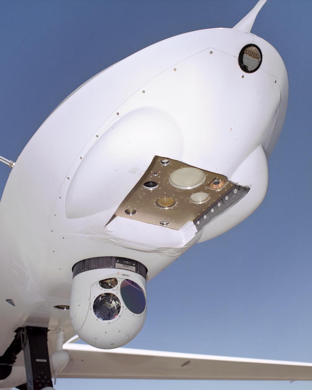
An ocean color senor, a passive microwave vertical sounder and an electro-optical sensor were mounted on the Altair UAV for the NOAA-NASA flight demonstration.

Terrence Hertz, Deputy Associate Administrator for Technology, NASA Aeronautics Research Mission Directorate, at the NOAA/NASA Altair flight demo kickoff.
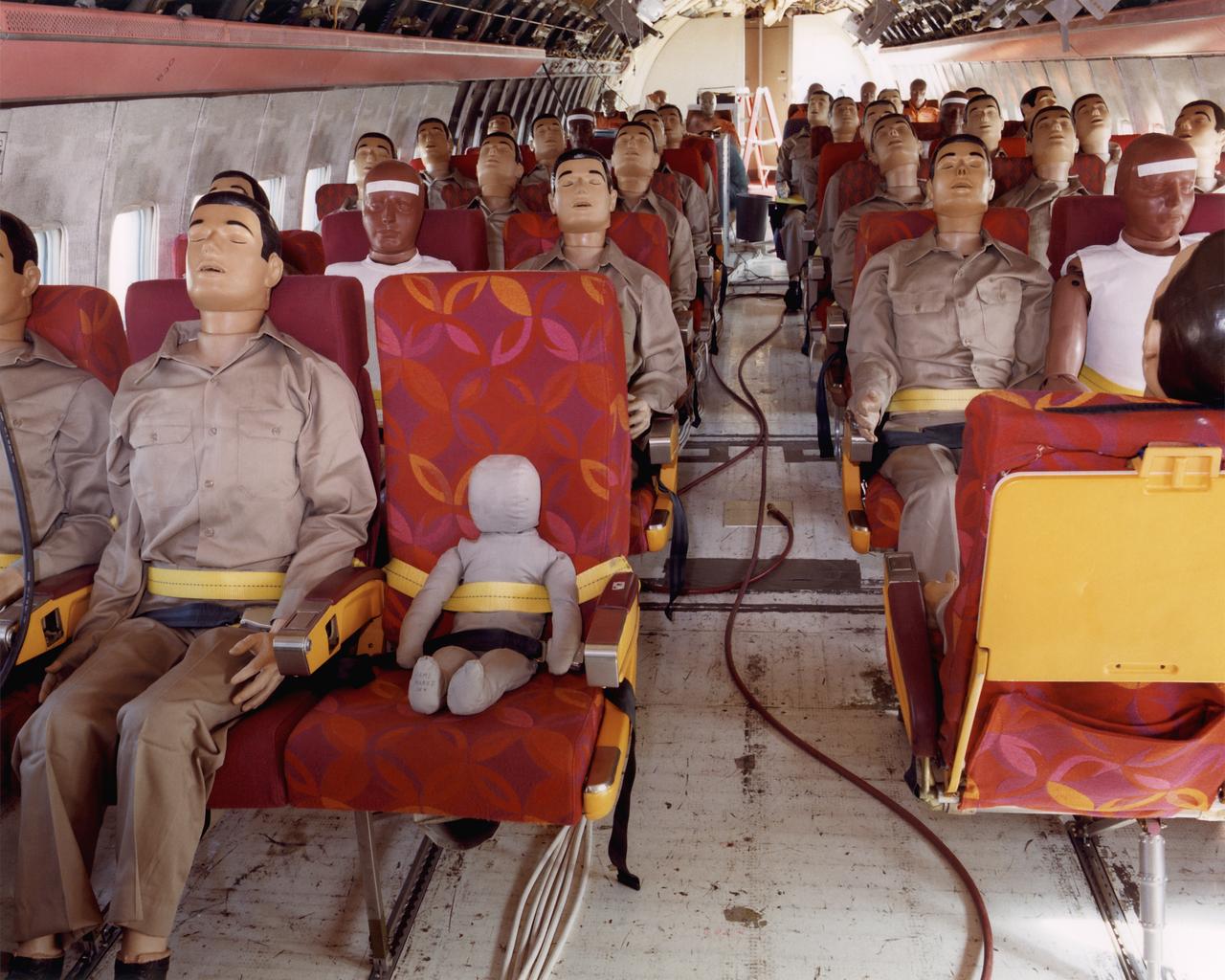
Controlled Impact Demonstration instrumented test dummies installed in plane.
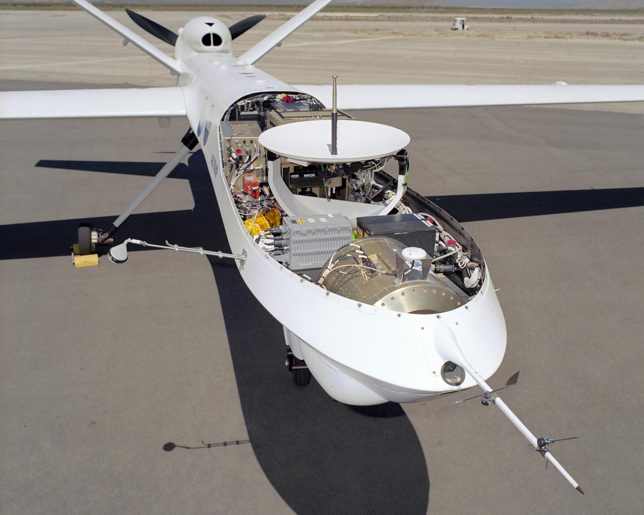
A satellite antenna, electro-optical/infrared and ocean color sensors (front) were among payloads installed on the Altair for the NOAA-NASA flight demonstration
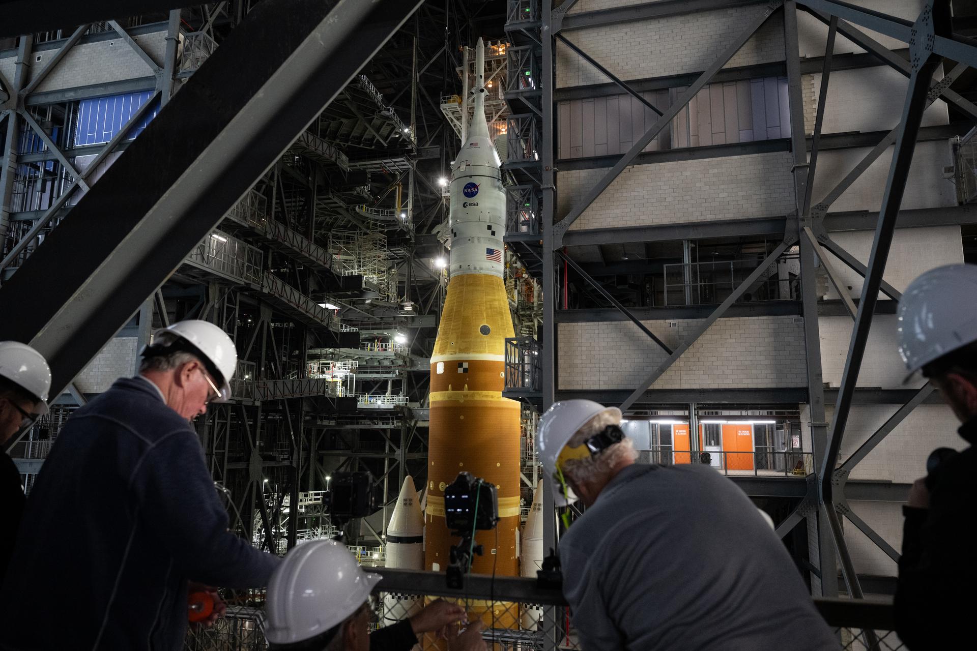
Members of the media are seen as they setup remote cameras to photograph the rollout of NASA’s Artemis II SLS (Space Launch System) rocket and Orion spacecraft inside the Vehicle Assembly building as preparations continue for rollout to Launch Pad 39B, Friday, Jan. 16, 2026, at NASA’s Kennedy Space Center in Florida. NASA’s Artemis II flight test will take Commander Reid Wiseman, Pilot Victor Glover, and Mission Specialist Christina Koch from NASA, and Mission Specialist Jeremy Hansen from the CSA (Canadian Space Agency), around the Moon and back to Earth no later than April 2026. Photo Credit: (NASA/Joel Kowsky)
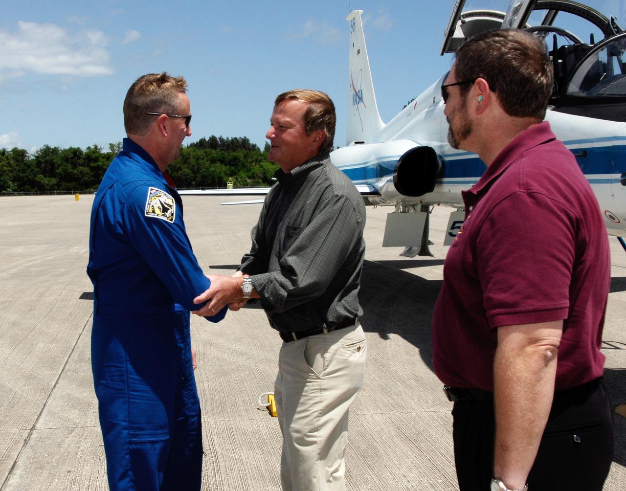
CAPE CANAVERAL, Fla. -- The crew of space shuttle Discovery's STS-124 mission arrives at the Shuttle Landing Facility at NASA's Kennedy Space Center aboard T-38 jet trainers to get ready for launch. At left, Pilot Ken Ham is greeted by Shuttle Launch Director Mike Leinbach. At right is the director of Launch Vehicle Processing, Mike Wetmore. Launch of Discovery is scheduled for 5:02 p.m. May 31. On the STS-124 mission, the crew of seven will deliver and install the Japanese Experiment Module – Pressurized Module and Japanese Remote Manipulator System. Photo credit: NASA/Kim Shiflett
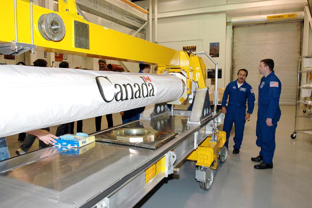
KENNEDY SPACE CENTER, FLA. - In the Remote Manipulator Lab inside the Vehicle Assembly Building, STS-114 Mission Specialist Charles Camarda (left) and Pilot James Kelly look at the new 50-foot-long Orbiter Boom Sensor System (OBSS) that will fly on Shuttle Discovery on Return to Flight mission STS-114. The OBSS attaches to the end of the Shuttle’s robotic arm. The system is one of the new safety measures for Return to Flight, equipping the orbiter with cameras and laser systems to inspect the Shuttle's Thermal Protection System while in space. Crew members are at Kennedy to become familiar with Shuttle equipment such as the OBSS and the newly redesigned External Tank. The launch window is May 12 to June 3, 2005.
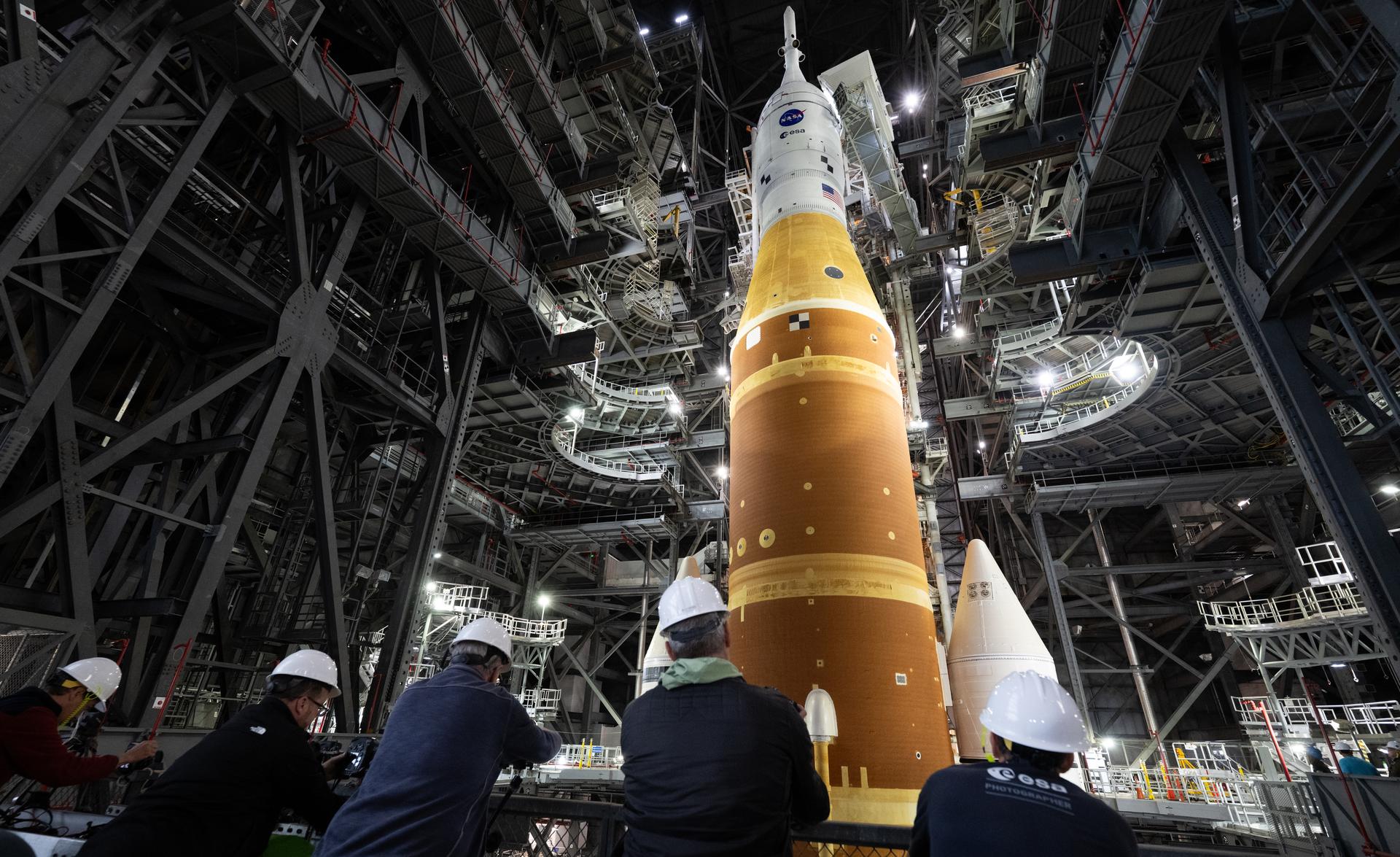
Members of the media are seen as they setup remote cameras to photograph the rollout of NASA’s Artemis II SLS (Space Launch System) rocket and Orion spacecraft inside the Vehicle Assembly building as preparations continue for rollout to Launch Pad 39B, Friday, Jan. 16, 2026, at NASA’s Kennedy Space Center in Florida. NASA’s Artemis II flight test will take Commander Reid Wiseman, Pilot Victor Glover, and Mission Specialist Christina Koch from NASA, and Mission Specialist Jeremy Hansen from the CSA (Canadian Space Agency), around the Moon and back to Earth no later than April 2026. Photo Credit: (NASA/Joel Kowsky)
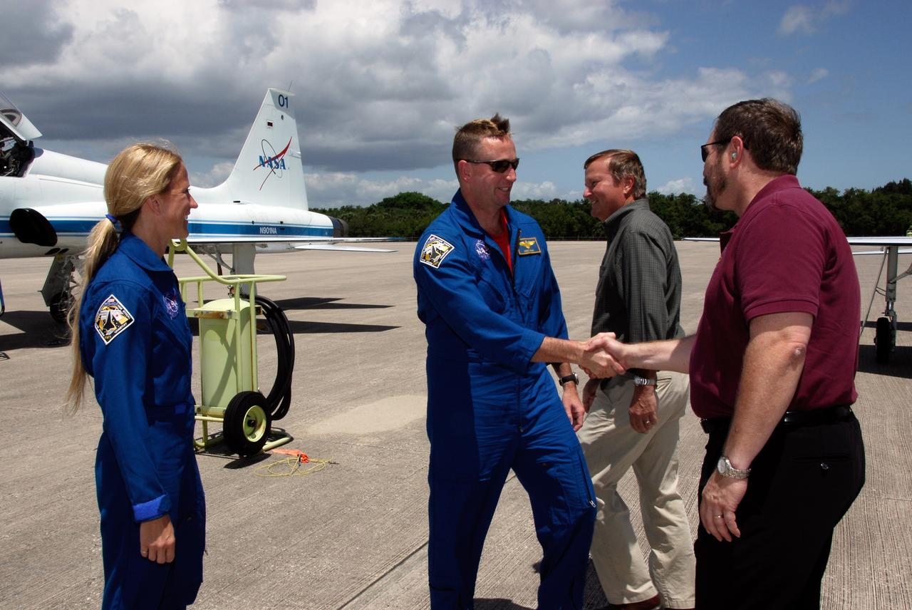
CAPE CANAVERAL, Fla. -- The crew of space shuttle Discovery's STS-124 mission arrives at the Shuttle Landing Facility at NASA's Kennedy Space Center aboard T-38 jet trainers to get ready for launch. At left is Mission Specialist Karen Nyberg; at center, Pilot Ken Ham is greeted by the director of Launch Vehicle Processing, Mike Wetmore. Behind them is Shuttle Launch Director Mike Leinbach. Launch of Discovery is scheduled for 5:02 p.m. May 31. On the STS-124 mission, the crew of seven will deliver and install the Japanese Experiment Module – Pressurized Module and Japanese Remote Manipulator System. Photo credit: NASA/Kim Shiflett
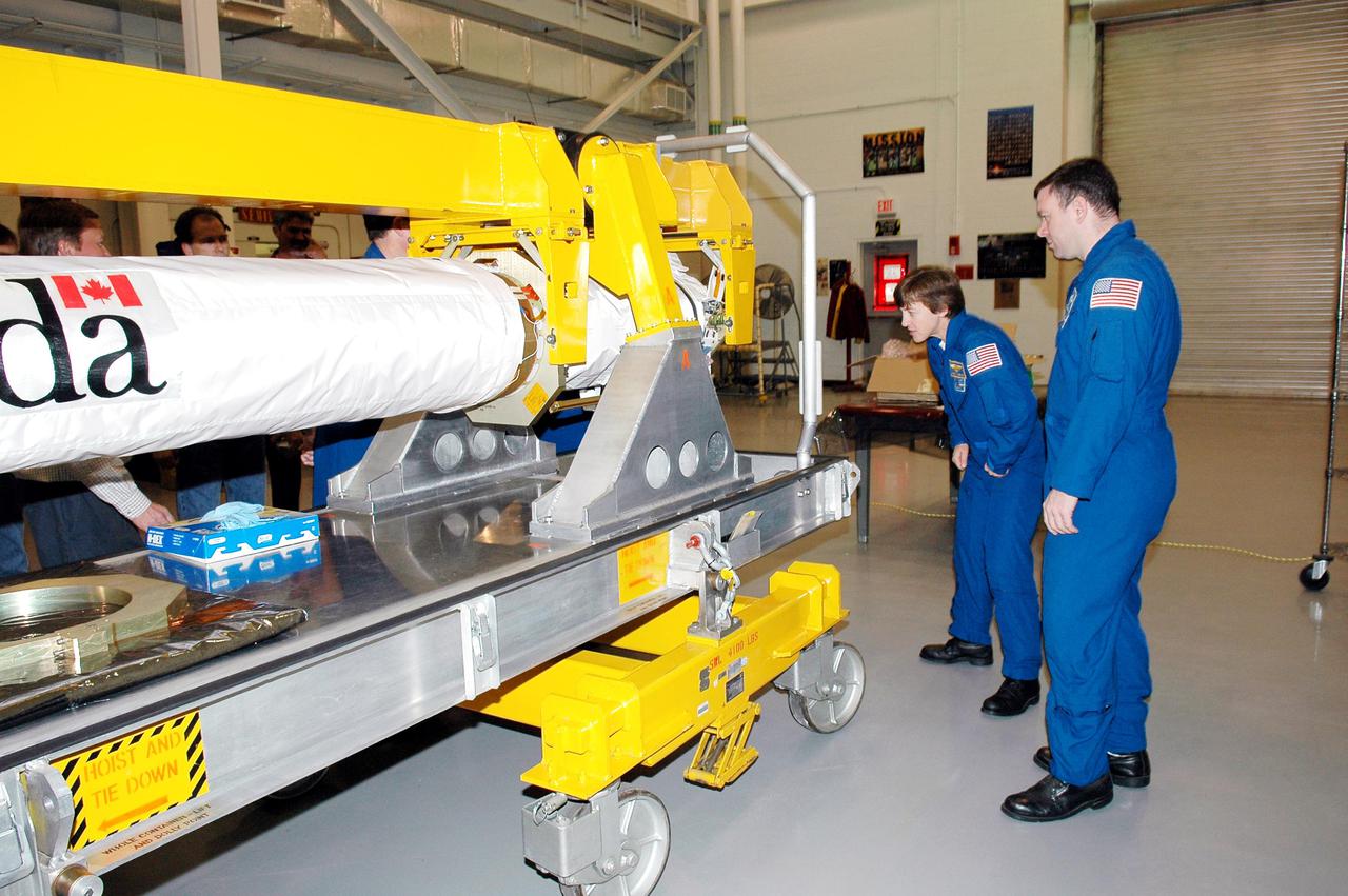
KENNEDY SPACE CENTER, FLA. - In the Remote Manipulator Lab inside the Vehicle Assembly Building, STS-114 Mission Specialist Wendy Lawrence and Pilot James Kelly look at the new 50-foot-long Orbiter Boom Sensor System (OBSS) that will fly on Shuttle Discovery on Return to Flight mission STS-114. The OBSS attaches to the end of the Shuttle’s robotic arm. The system is one of the new safety measures for Return to Flight, equipping the orbiter with cameras and laser systems to inspect the Shuttle's Thermal Protection System while in space. Crew members are at Kennedy to become familiar with Shuttle equipment such as the OBSS and the newly redesigned External Tank. The launch window is May 12 to June 3, 2005.

The back seat instrument panel on the NASA T-34C chase plane. In its role as a military trainer, the instructor pilot would ride in the back seat, while the student would be in the front seat. As a chase plane, the back seat would be occupied by a photographer. The aircraft was previously used at the Lewis Research Center in propulsion experiments involving turboprop engines, and was used as a chase aircraft at Dryden for smaller and slower research projects. Chase aircraft accompany research flights for photography and video purposes, and also as support for safety and research. At Dryden, the T-34 is used mainly for smaller remotely piloted vehicles which fly slower than NASA's F-18's, used for larger scale projects. This aircraft was returned to the U.S. Navy in May of 2002. The T-34C, built by Beech, carries a crew of 2 and is nicknamed the Mentor.
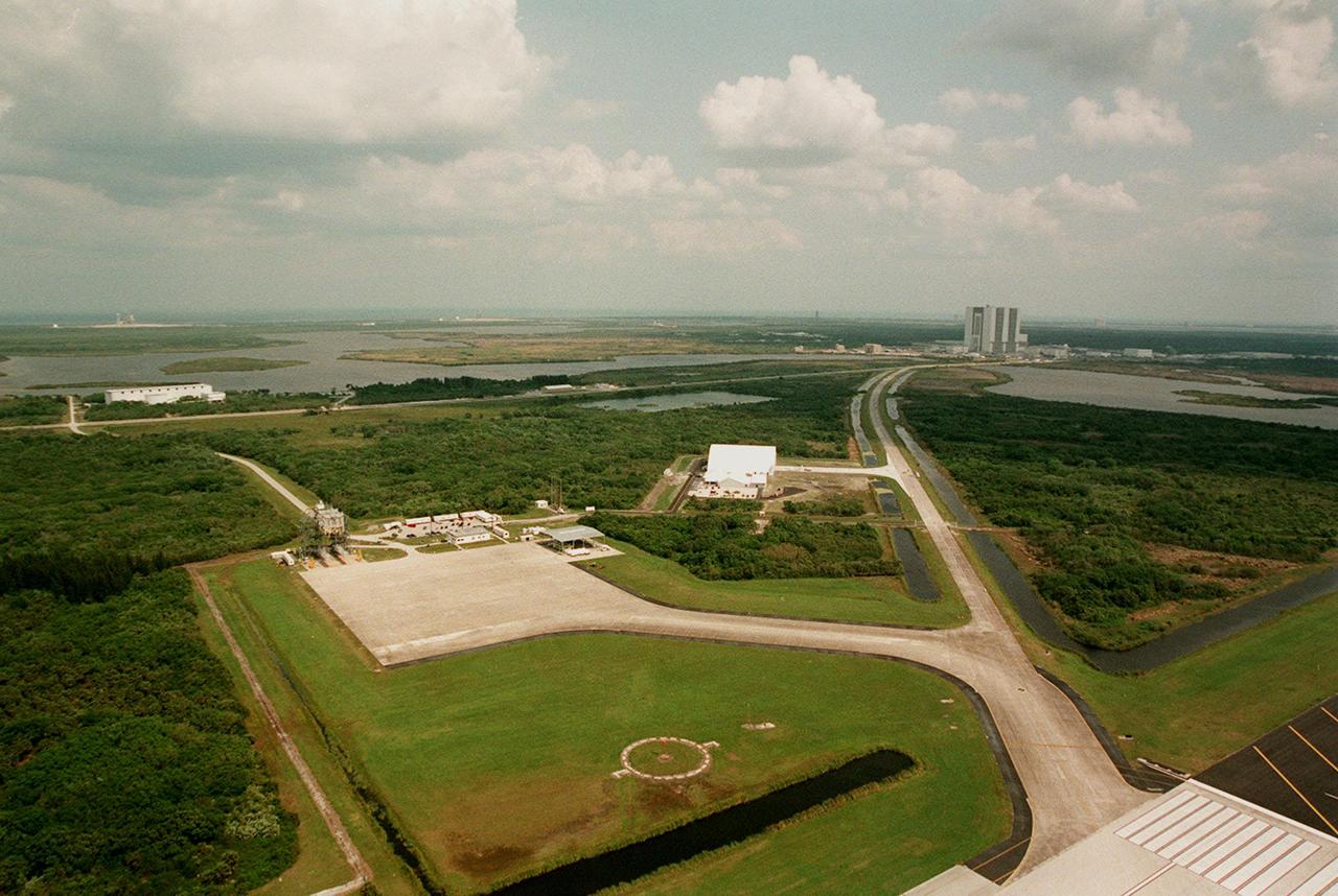
A broad aerial view west of Launch Complex 39 Area shows a multitude of facilities. Starting with the Shuttle Landing Facility, at bottom center is a circle around a windsock, a landing aid for pilots; at bottom right is a portion of the landing strip. In the center is the parking tarmac with its mate/demate device on the left corner. To the right is the remote launch vehicle hangar, still under construction. At the upper right is the Vehicle Assembly Building (VAB). The tow-way road runs from the landing strip to the Orbiter Processing Facility, next to the VAB. The Kennedy Parkway North extends from the left side toward the VAB. The long white building next to the parkway is the Apollo/Saturn V Center. Above it, slightly visible on the horizon (left), is Launch Complex 39, Pad B.

A NASA T-34C aircraft, used for safety chase, is shown flying above the Dryden Flight Research Center, Edwards, California in March 1997. The aircraft was previously used at the Lewis Research Center in propulsion experiments involving turboprop engines, and was used as a chase aircraft at Dryden for smaller and slower research projects. Chase aircraft accompany research flights for photography and video purposes, and also as support for safety and research. At Dryden, the T-34 is used mainly for smaller remotely piloted vehicles which fly slower than NASA's F-18's, used for larger scale projects. This aircraft was returned to the U.S. Navy in May of 2002. The T-34C, built by Beech, carries a crew of 2 and is nicknamed the Mentor.

A NASA T-34C aircraft, used for safety chase, is shown flying above the Dryden Flight Research Center, Edwards, California in March 1997. The aircraft was previously used at the Lewis Research Center in propulsion experiments involving turboprop engines, and was used as a chase aircraft at Dryden for smaller and slower research projects. Chase aircraft accompany research flights for photography and video purposes, and also as support for safety and research. At Dryden, the T-34 is used mainly for smaller remotely piloted vehicles which fly slower than NASA's F-18's, used for larger scale projects. This aircraft was returned to the U.S. Navy in May of 2002. The T-34C, built by Beech, carries a crew of 2 and is nicknamed the Mentor.
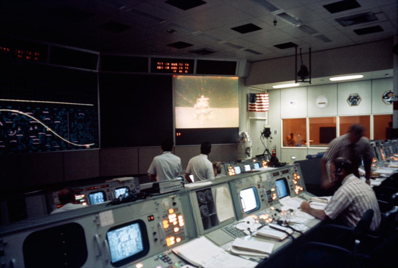
S71-41759 (2 Aug. 1971) --- A partial view of activity in the Mission Operations Control Room in the Mission Control Center during the liftoff of the Apollo 15 Lunar Module "Falcon" ascent stage from the lunar surface. An RCA color television camera mounted on the Lunar Roving Vehicle made it possible for people on Earth to watch the LM's spectacular launch from the moon. The LM liftoff was at 171:37 ground elapsed time. The LRV was parked about 300 feet east of the LM. The TV camera was remotely controlled from a console in the MOCR. Seated in the right foreground is astronaut Edgar D. Mitchell, a spacecraft communicator. Mitchell was lunar module pilot of the Apollo 14 lunar landing mission. Note liftoff on the television monitor in the center background.
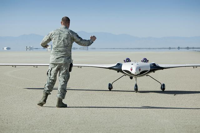
The X-56A Multi-Utility Technology Testbed (MUTT) is greeted on an Edwards Air Force Base runway by a U.S. Air Force Research Laboratory (AFRL) team member. NASA’s Armstrong Flight Research Center and the AFRL, along with participants from Langley Research Center and Glenn Research Center, and support from Lockheed Martin, are using the second X-56A (dubbed “Buckeye”) to check out aircraft systems, evaluate handling qualities, characterize and expand the airplane’s performance envelope, and verify pre-flight predictions regarding aircraft behavior. The 20-minute flight marked the beginning of a research effort designed to yield significant advances in aeroservoelastic technology using a low-cost, modular, remotely piloted aerial vehicle.
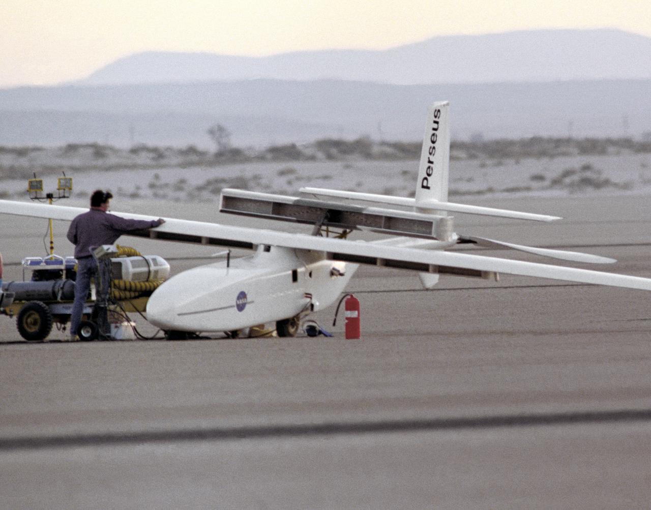
The Perseus A, a remotely-piloted, high-altitude research vehicle, is seen just after landing on Rogers Dry Lake at the Dryden Flight Research Center, Edwards, California. The Perseus A had a unique method of takeoff and landing. To make the aircraft as aerodynamic and lightweight as possible, designers gave it only two very small centerline wheels for landing. These wheels were very close to the fuselage, and therefore produced very little drag. However, since the fuselage sat so close to the ground, it was necessary to keep the large propeller at the rear of the aircraft locked in a horizontal position during takeoff. The aircraft was towed to about 700 feet in the air, where the engine was started and the aircraft began flying under its own power.
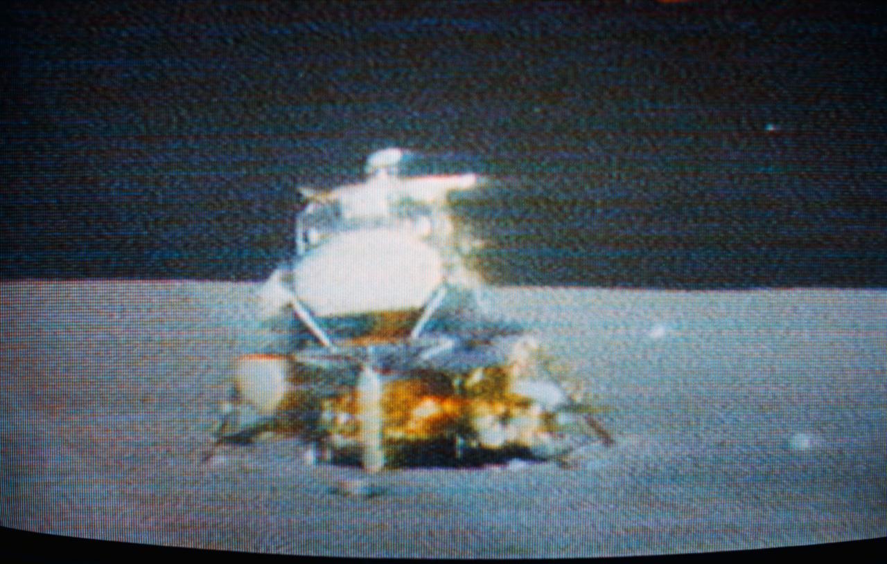
S71-41511 (2 Aug. 1971) --- The Apollo 15 Lunar Module (LM) "Falcon" is seen only seconds before ascent stage liftoff in this color reproduction taken from a transmission made by the RCA color television camera mounted on the Lunar Roving Vehicle (LRV). The LRV was parked about 300 feet east of the LM. The LRV-mounted TV camera, remotely controlled from the Mission Control Center (MCC), made it possible for people on Earth to watch the LM's launch from the moon. The LM liftoff was at 171:37 ground elapsed time. The "Falcon" ascent stage, with astronauts David R. Scott, commander; and James B. Irwin, lunar module pilot, aboard, returned from the lunar surface to rejoin the Command and Service Modules (CSM) orbiting the moon. Astronaut Alfred M. Worden, command module pilot, remained with the CSM in lunar orbit while Scott and Irwin explored the moon. The LM descent stage is used as a launching platform and remains behind on the moon. This is part one of a four-part sequence.
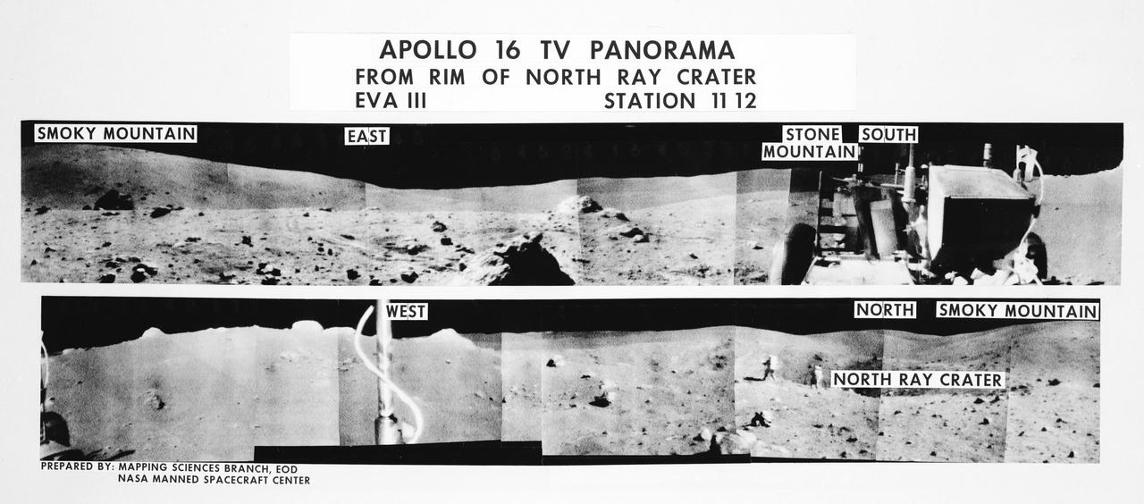
S72-35971 (21 April 1972) --- A 360-degree field of view of the Apollo 16 Descartes landing site area composed of individual scenes taken from color transmission made by the color RCA TV camera mounted on the Lunar Roving Vehicle (LRV). This panorama was made while the LRV was parked at the rim of North Ray Crater (Stations 11 & 12) during the third Apollo 16 lunar surface extravehicular activity (EVA) by astronauts John W. Young and Charles M. Duke Jr. The overlay identifies the directions and the key lunar terrain features. The camera panned across the rear portion of the LRV in its 360-degree sweep. Note Young and Duke walking along the edge of the crater in one of the scenes. The TV camera was remotely controlled from a console in the Mission Control Center (MCC). Astronauts Young, commander; and Duke, lunar module pilot; descended in the Apollo 16 Lunar Module (LM) "Orion" to explore the Descartes highlands landing site on the moon. Astronaut Thomas K. Mattingly II, command module pilot, remained with the Command and Service Modules (CSM) "Casper" in lunar orbit.
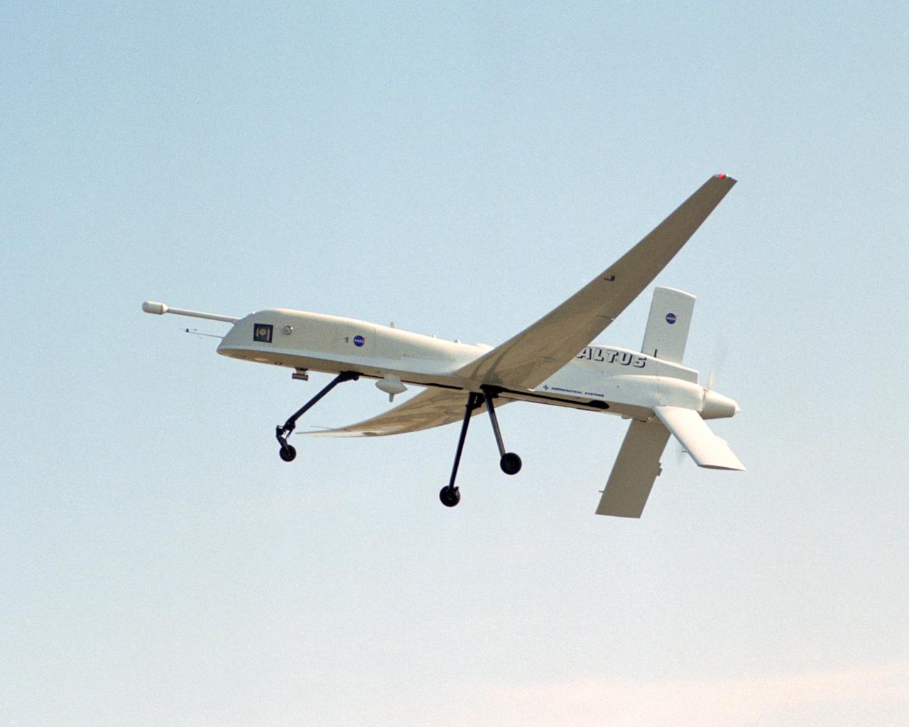
A NASA team studying the causes of electrical storms and their effects on our home planet achieved a milestone on August 21, 2002, completing the study's longest-duration research flight and monitoring four thunderstorms in succession. Based at the Naval Air Station Key West, Florida, researchers with the Altus Cumulus Electrification Study (ACES) used the Altus II remotely-piloted aircraft to study thunderstorms in the Atlantic Ocean off Key West and the west of the Everglades. The ACES lightning study used the Altus II twin turbo uninhabited aerial vehicle, built by General Atomics Aeronautical Systems, Inc. of San Diego. The Altus II was chosen for its slow flight speed of 75 to 100 knots (80 to 115 mph), long endurance, and high-altitude flight (up to 65,000 feet). These qualities gave the Altus II the ability to fly near and around thunderstorms for long periods of time, allowing investigations to be to be conducted over the entire life cycle of storms. The vehicle has a wing span of 55 feet and a payload capacity of over 300 lbs. With dual goals of gathering weather data safely and testing the adaptability of the uninhabited aircraft, the ACES study is a collaboration among the Marshall Space Flight Center, the University of Alabama in Huntsville, NASA,s Goddard Space Flight Center in Greenbelt, Maryland, Pernsylvania State University in University Park, and General Atomics Aeronautical Systems, Inc.
A NASA team studying the causes of electrical storms and their effects on our home planet achieved a milestone on August 21, 2002, completing the study's longest-duration research flight and monitoring four thunderstorms in succession. Based at the Naval Air Station Key West, Florida, researchers with the Altus Cumulus Electrification Study (ACES) used the Altus II remotely piloted aircraft to study thunderstorms in the Atlantic Ocean off Key West and the west of the Everglades. The ACES lightning study used the Altus II twin turbo uninhabited aerial vehicle, built by General Atomics Aeronautical Systems, Inc. of San Diego. The Altus II was chosen for its slow flight speed of 75 to 100 knots (80 to 115 mph), long endurance, and high-altitude flight (up to 65,000 feet). These qualities gave the Altus II the ability to fly near and around thunderstorms for long periods of time, allowing investigations to be conducted over the entire life cycle of storms. The vehicle has a wing span of 55 feet and a payload capacity of over 300 lbs. With dual goals of gathering weather data safely and testing the adaptability of the uninhabited aircraft, the ACES study is a collaboration among the Marshall Space Flight Center, the University of Alabama in Huntsville, NASA's Goddard Space Flight Center in Greenbelt, Maryland, Pernsylvania State University in University Park, and General Atomics Aeronautical Systems, Inc.
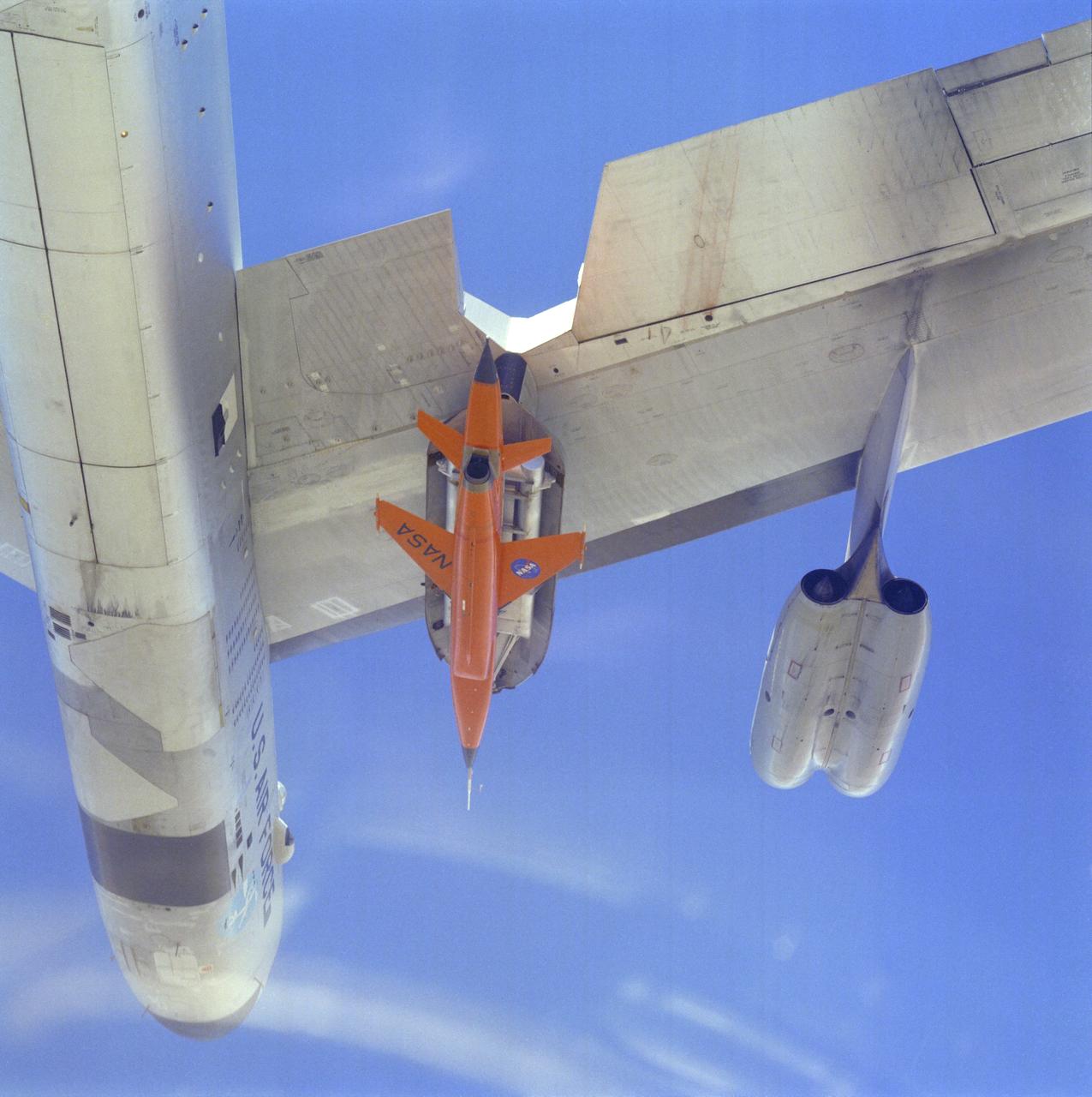
First Captive Flight of DAST Mated to B-52 - Close-up from Below
Equipped with a pod-mounted infrared imaging sensor, the Altair UAS aided fire mapping efforts over wildfires in central and southern California in late 2006.
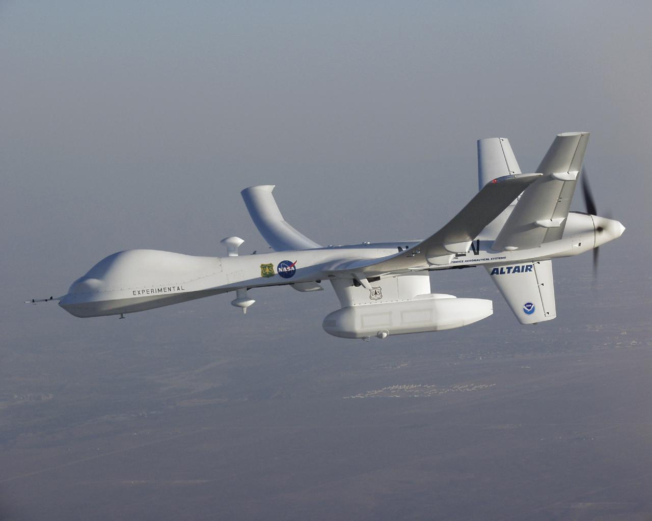
A high-tech infrared imaging sensor in its underbelly pod, the Altair UAS flew repeated passes over the Esperanza fire to aid firefighting efforts.
DAST in Flight. Last Flight
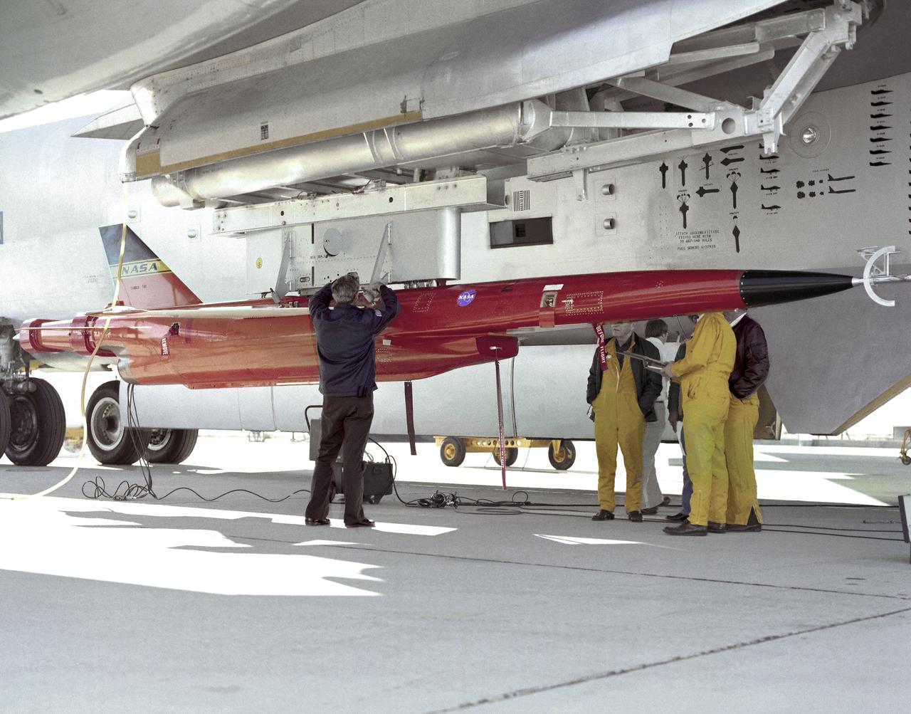
DAST Mated to B-52 on Ramp - Close-up
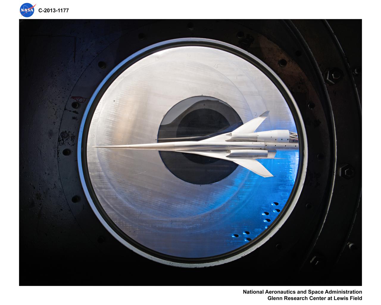
Supersonic Aircraft Model The window in the sidewall of the 8- by 6-foot supersonic wind tunnel at NASA's Glenn Research Center shows a 1.79 percent scale model of a future concept supersonic aircraft built by The Boeing Company. In recent tests, researchers evaluated the performance of air inlets mounted on top of the model to see how changing the amount of airflow at supersonic speeds through the inlet affected performance. The inlet on the pilot's right side (top inlet in this side view) is larger because it contains a remote-controlled device through which the flow of air could be changed. The work is part of ongoing research in NASA's Aeronautics Research Mission Directorate to address the challenges of making future supersonic flight over land possible. Researchers are testing overall vehicle design and performance options to reduce emissions and noise, and identifying whether the volume of sonic booms can be reduced to a level that leads to a reversal of the current ruling that prohibits commercial supersonic flight over land. Image Credit: NASA/Quentin Schwinn
S82-26315 (4 Feb. 1982) --- This is the insignia for NASA's third flight (STS-3) of the Space Transportation System's (STS) Columbia, depicted in the middle of the blue sphere against the background of the sun. The Columbia's tail, nose, and top will each be pointed at the sun for long periods to test its thermal response to extremes of temperatures. The three prominent rays represent the third STS flight. The surnames of astronauts Jack R. Lousma, commander, and C. Gordon Fullerton, pilot, flank the vehicle, and the name Columbia appears at the bottom. The spacecraft's payload bay doors are open, and the Remote Manipulator System (RMS) arm with an experimental payload is extended as it will be on several occasions during the actual flight, scheduled for spring of this year. The artwork was accomplished by space artist Robert C. McCall of Paradise Valley, Arizona. The NASA insignia design for space shuttle flights is reserved for use by the astronauts and for other official use as the NASA Administrator may authorize. Public availability has been approved only in the forms of illustrations by the various news media. When and if there is any change in this policy, which is not anticipated, the change will be publicly announced. Photo credit: NASA
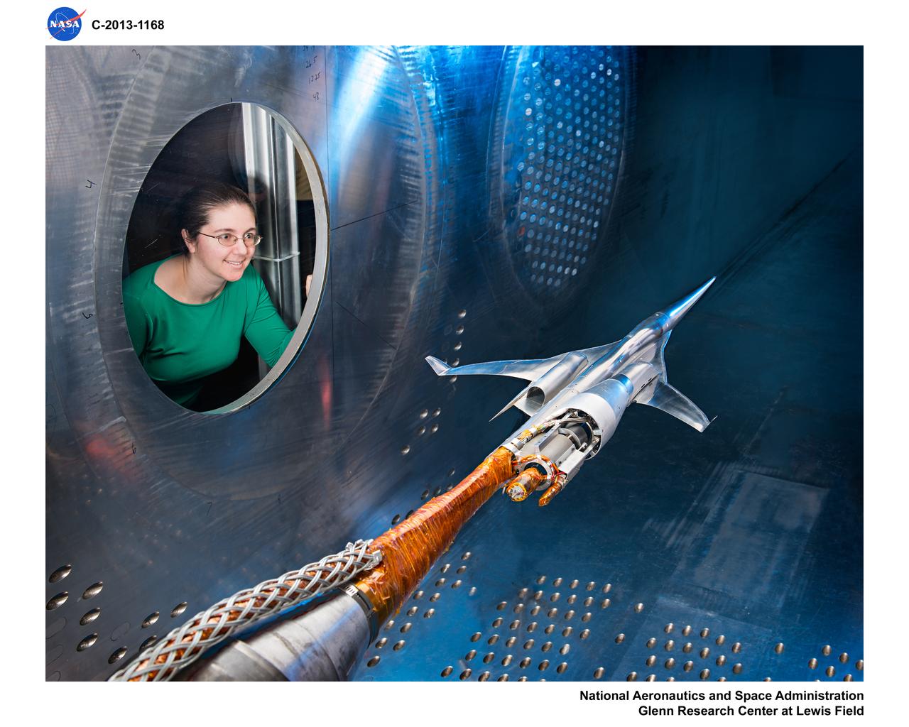
Supersonic Aircraft Model The window in the sidewall of the 8- by 6-foot supersonic wind tunnel at NASA's Glenn Research Center shows a 1.79 percent scale model of a future concept supersonic aircraft built by The Boeing Company. In recent tests, researchers evaluated the performance of air inlets mounted on top of the model to see how changing the amount of airflow at supersonic speeds through the inlet affected performance. The inlet on the pilot's right side (top inlet in this side view) is larger because it contains a remote-controlled device through which the flow of air could be changed. The work is part of ongoing research in NASA's Aeronautics Research Mission Directorate to address the challenges of making future supersonic flight over land possible. Researchers are testing overall vehicle design and performance options to reduce emissions and noise, and identifying whether the volume of sonic booms can be reduced to a level that leads to a reversal of the current ruling that prohibits commercial supersonic flight over land. Image Credit: NASA/Quentin Schwinn
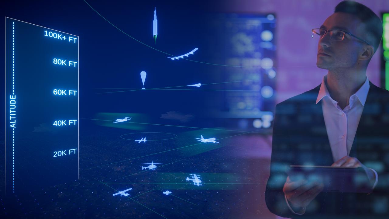
For NASA’s Advanced Air Mobility mission's vision to be successful, partners in industry and government must develop new air traffic management technologies. This concept art represents how different types of aircraft could fly safely and efficiently in a busy airspace with the help of new air traffic management technologies.