The Fuel Burner Rig is a test laboratory at NASA Glenn, which subjects new jet engine materials, treated with protective coatings, to the hostile, high temperature, high velocity environment found inside aircraft turbine engines. These samples face 200-mile per hour flames to simulate the temperatures of aircraft engines in flight. The rig can also simulate aircraft carrier and dusty desert operations where salt and sand can greatly reduce engine life and performance.
Burner Rig Laboratory
The Plasma Spray-Physical Vapor Deposition (PS-PVD) Rig at NASA Glenn Research Center. The rig helps develop coatings for next-generation aircraft turbine components and create more efficient engines.
Vapor Deposition Rig
JERRIE COBB - PILOT - TESTING GIMBAL RIG IN THE ALTITUDE WIND TUNNEL, AWT
The Glenn Extreme Environment Chamber (GEER) simulates the extreme conditions found in space and tests many devices that will explore Venus to see if they can withstand the punishing environment and temperatures over 800 degrees F.
Extreme Environments Rig
FUEL CELL CONDENSER FOR THE APOLLO SYSTEM TEST RIG
NASA Glenn’s Natural Gas/Oxygen Burner Rig is used to study the high temperature performance of various metal alloys, ceramics, and protective coatings for aero and space propulsion systems. The burner rig provides an easily accessible and economical method to simulate engine operating conditions to understand thermomechanical and thermochemical degradation of materials and structures. In the photo, Materials Research Engineer Michael Presby uses an infrared pyrometer to monitor the surface temperature of the material for a test on February 23, 2024. Photo Credit: (NASA/Sara Lowthian-Hanna)
Engineering Design Unit (EDU) from a NASA customer, Radian Aerospace, being tested in the burner rig
NASA Glenn research engineers prepare our extreme environments chamber (GEER) for a test. GEER, which simulates the extreme conditions found in space, tests many devices that will explore Venus to see if they can withstand the punishing environment and temperatures over 800˚F.
Glenn Extreme Environment Rig (GEER)
Glenn's Extreme Environment Rig, GEER Mass Spectrometer
GRC-2016-C-09960
Structural Heat Intercept-Insulation-Vibration Evaluation Rig, SHIVER
SHIVER, B2, ISP, In-Space Propulsion Facility, Vacuum Chamber,
Structural Heat Intercept-Insulation-Vibration Evaluation Rig, SHIVER
SHIVER, B2, ISP, In-Space Propulsion Facility, Vacuum Chamber,
Structural Heat Intercept-Insulation-Vibration Evaluation Rig, SHIVER
SHIVER, B2, ISP, In-Space Propulsion Facility, Vacuum Chamber,
Structural Heat Intercept-Insulation-Vibration Evaluation Rig, SHIVER
SHIVER, B2, ISP, In-Space Propulsion Facility, Vacuum Chamber,
Structural Heat Intercept-Insulation-Vibration Evaluation Rig, SHIVER
SHIVER, B2, ISP, In-Space Propulsion Facility, Vacuum Chamber,
Daniel Gerges, Technician, poses for a portrait in the Glenn Extreme Environments Rig, GEER Lab
GRC-2022-C-00971
A burner rig heats up a material sample in the Materials and Stresses Building at the National Aeronautics and Space Administration (NASA) Lewis Research Center. Materials technology is an important element in the successful development of advanced airbreathing and rocket propulsion systems. Different types of engines operate in different environments so an array of dependable materials is needed. NASA Lewis began investigating the characteristics of different materials shortly after World War II. In 1949 the materials group was expanded into its own division. The Lewis researchers sought to study and test materials in environments that simulate the environment in which they would operate.     The Materials and Stresses Building, built in 1949, contained a number of laboratories to analyze the materials. They are subjected to high temperatures, high stresses, corrosion, irradiation, and hot gasses. The Physics of Solids Laboratory included a cyclotron, cloud chamber, helium cryostat, and metallurgy cave. The Metallographic Laboratory possessed six x-ray diffraction machines, two metalloscopes, and other equipment. The Furnace Room had two large induction machines, a 4500⁰ F graphite furnace, and heat treating equipment. The Powder Laboratory included 60-ton and 3000-ton presses. The Stresses Laboratory included stress rupture machines, fatigue machines, and tensile strength machines.
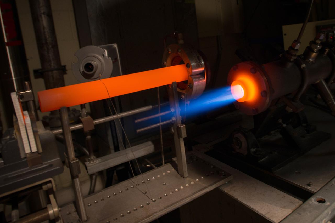
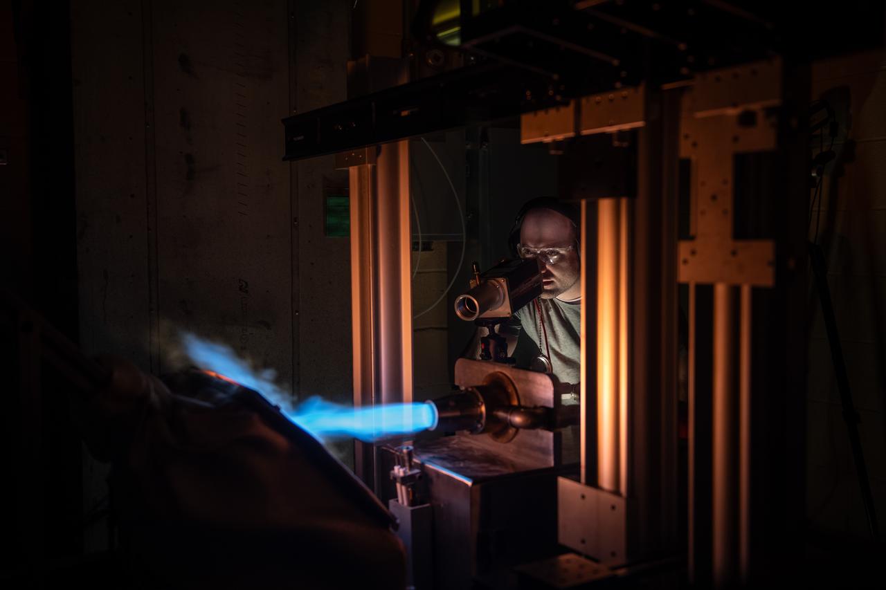
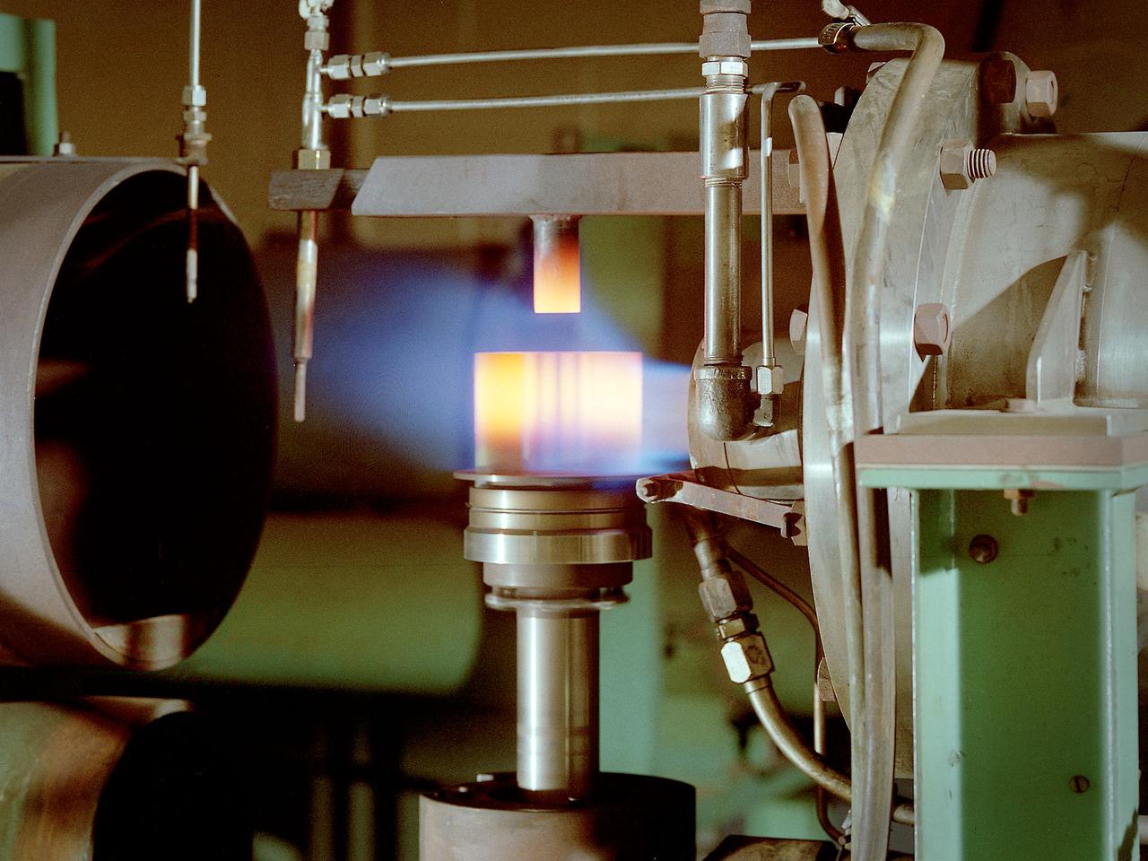
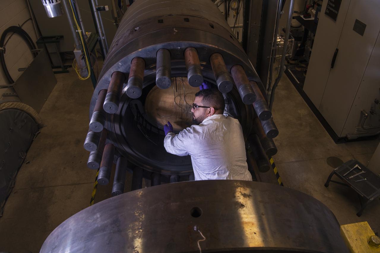
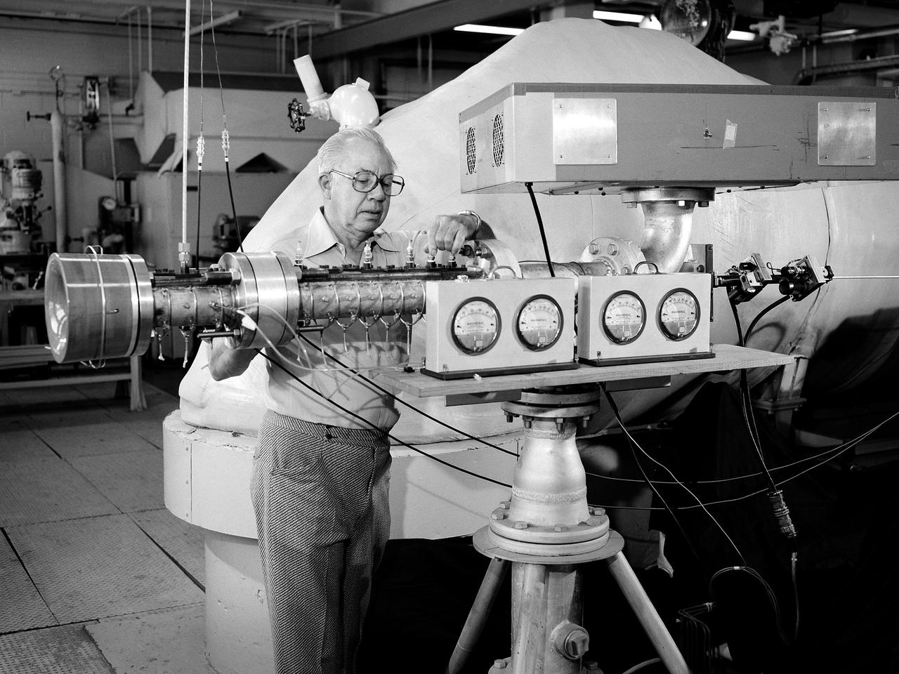
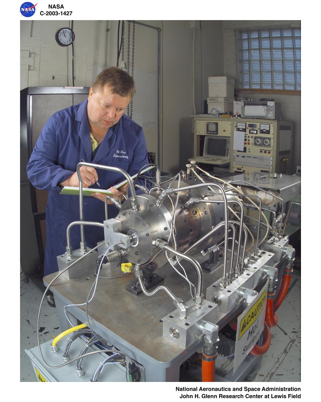
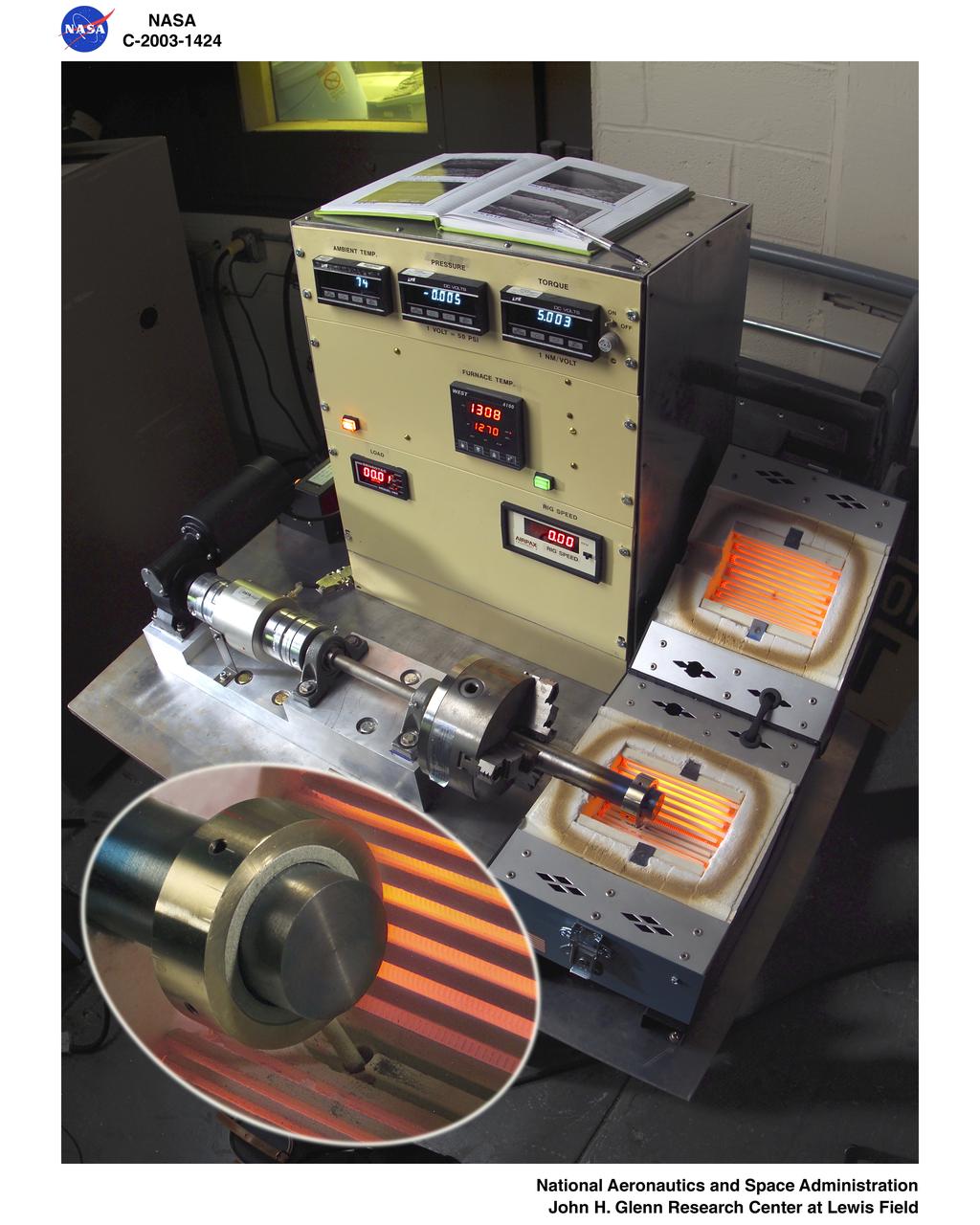
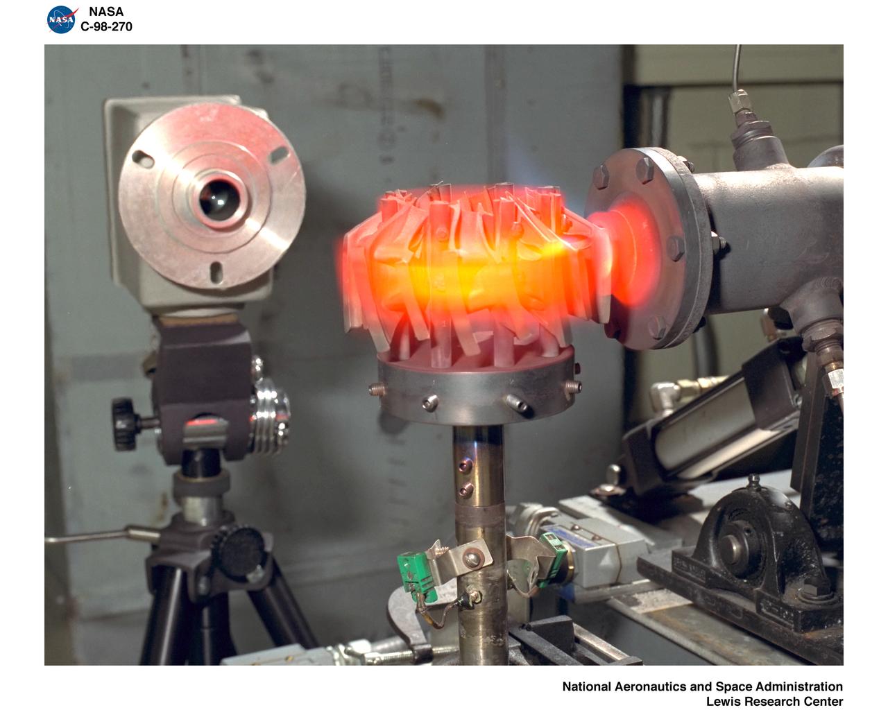
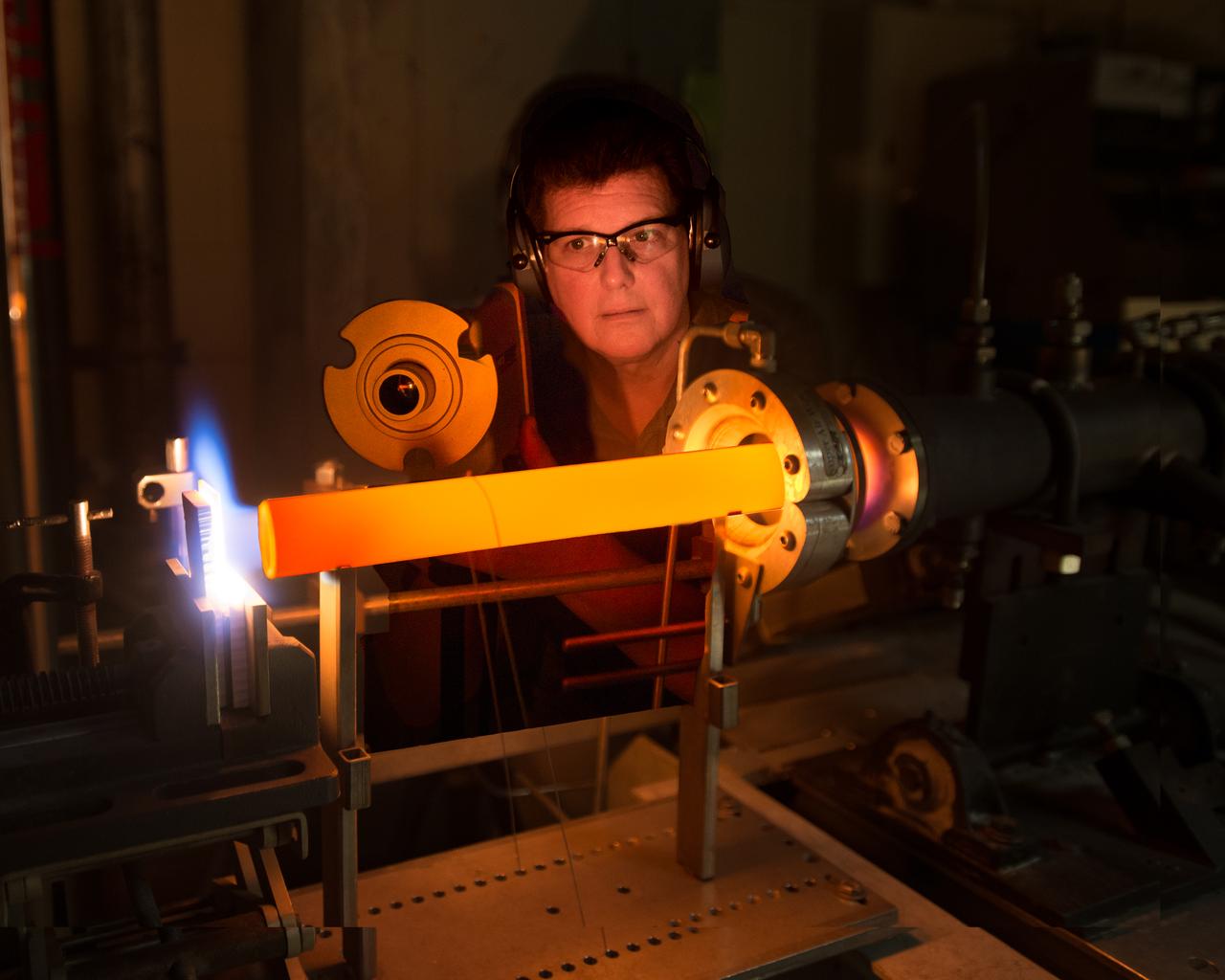
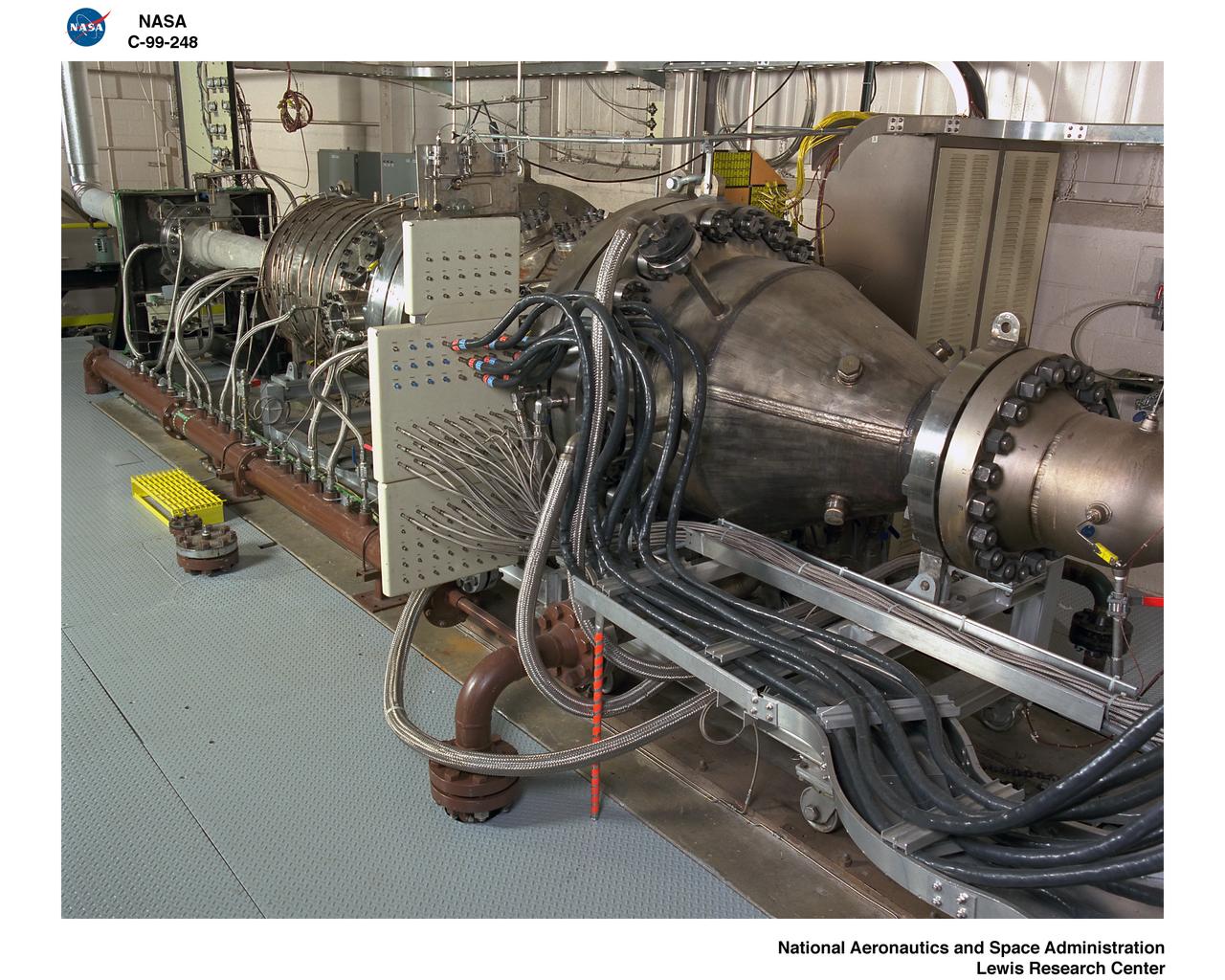
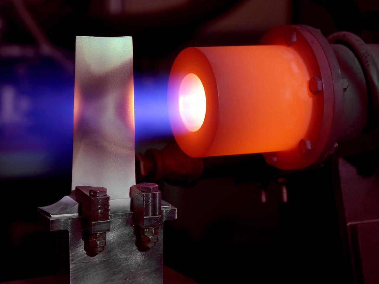
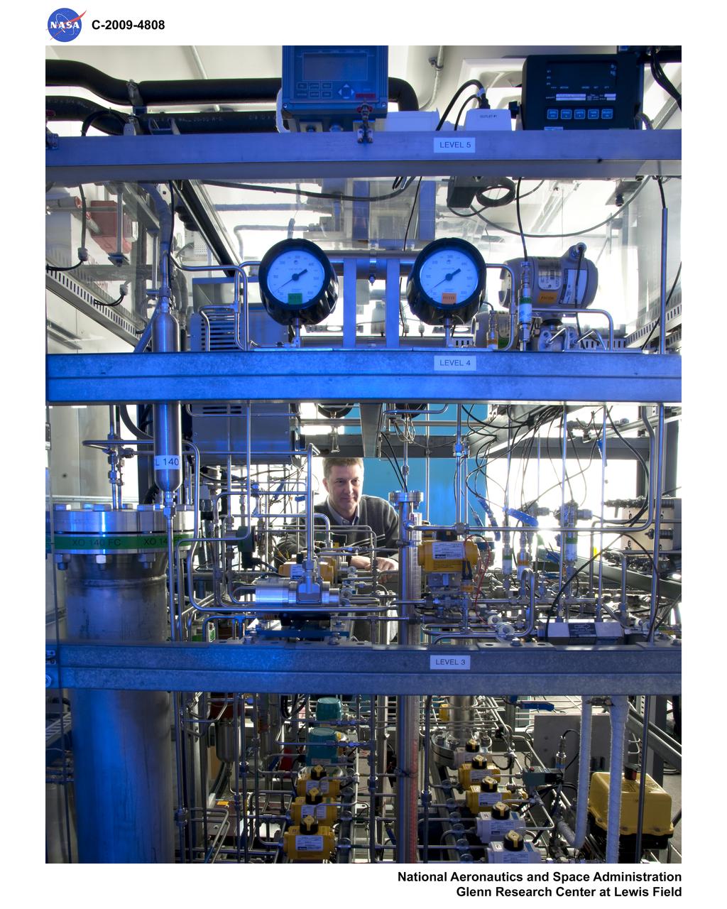
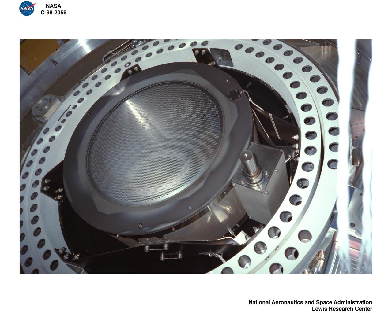
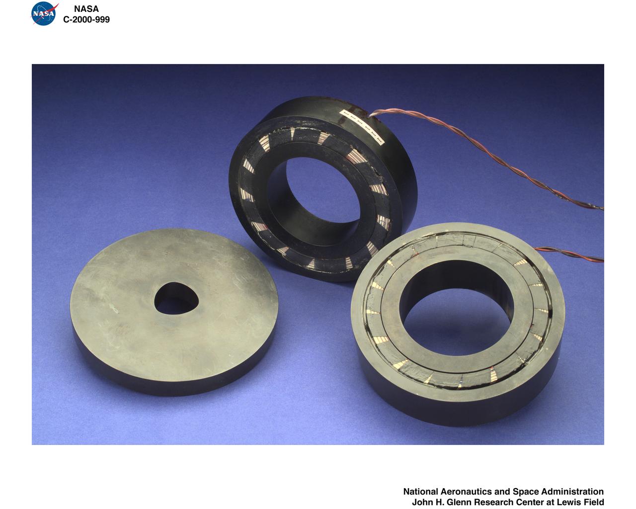
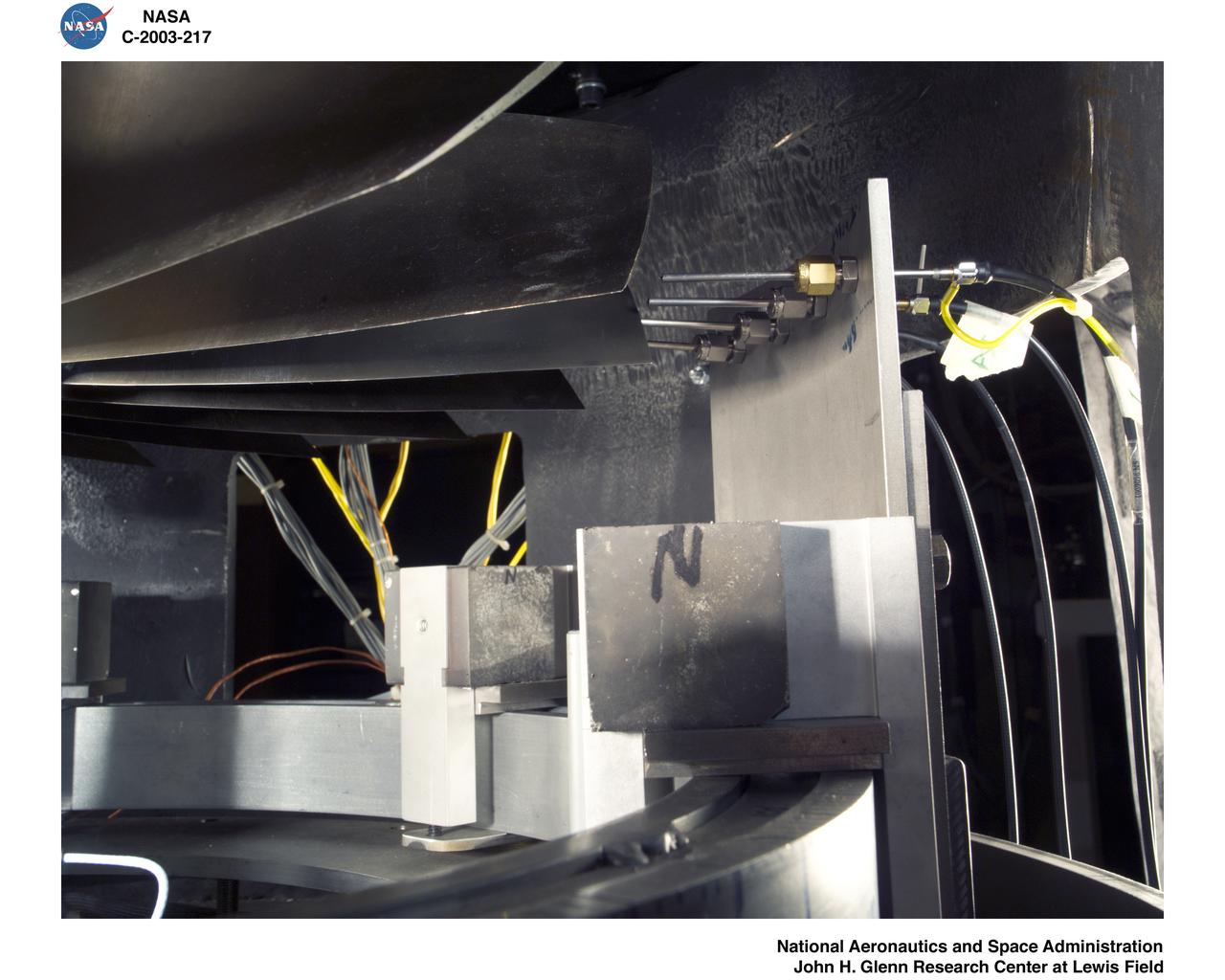
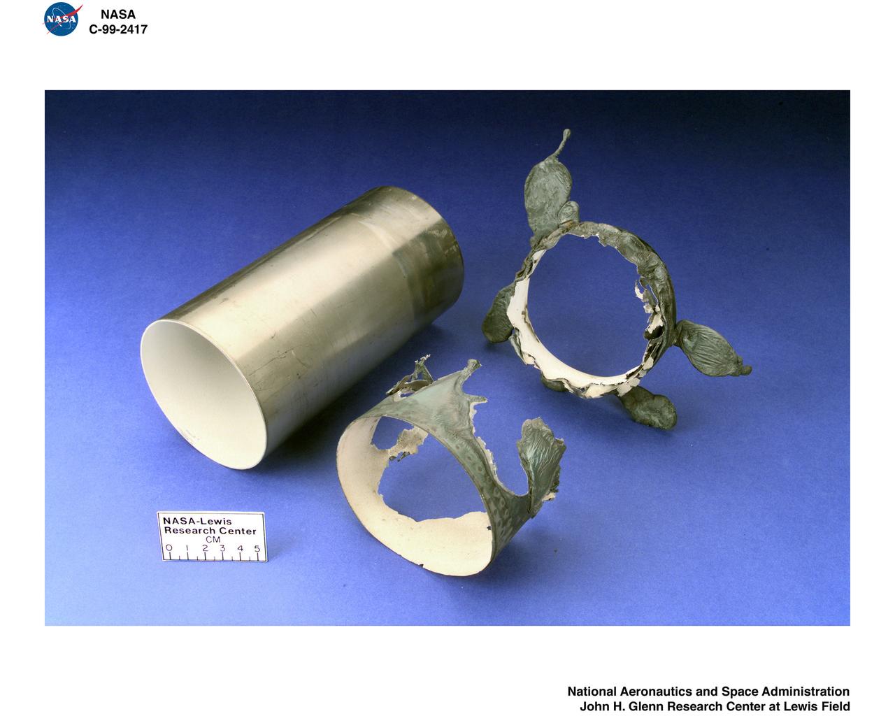
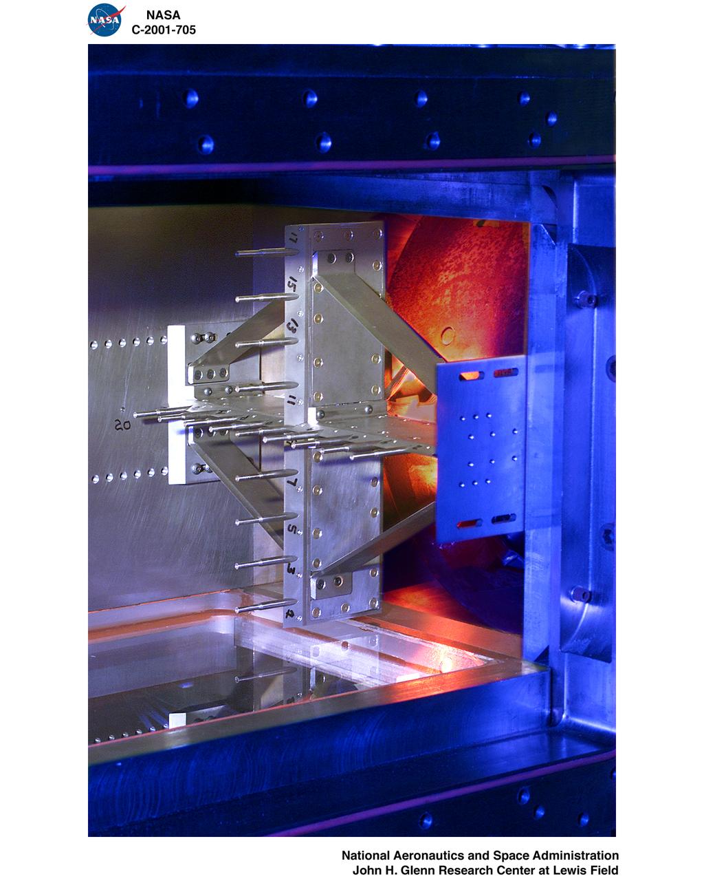
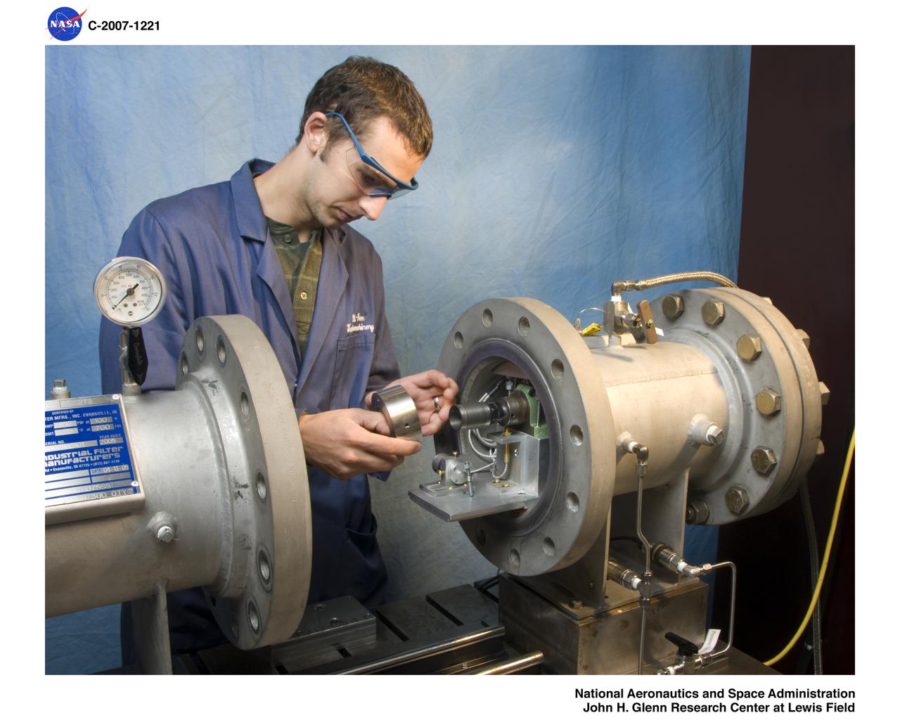
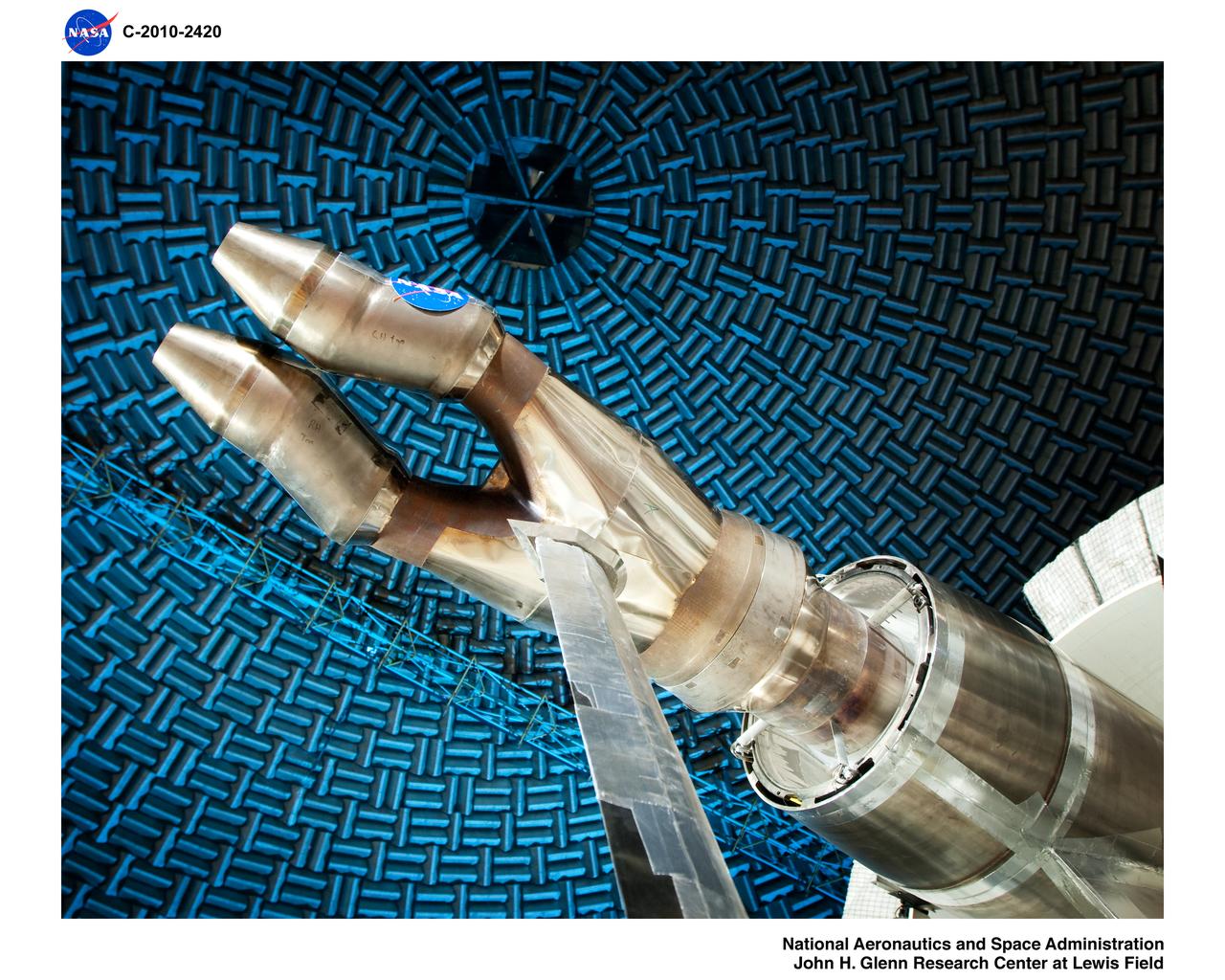
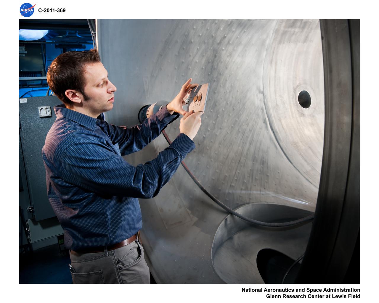
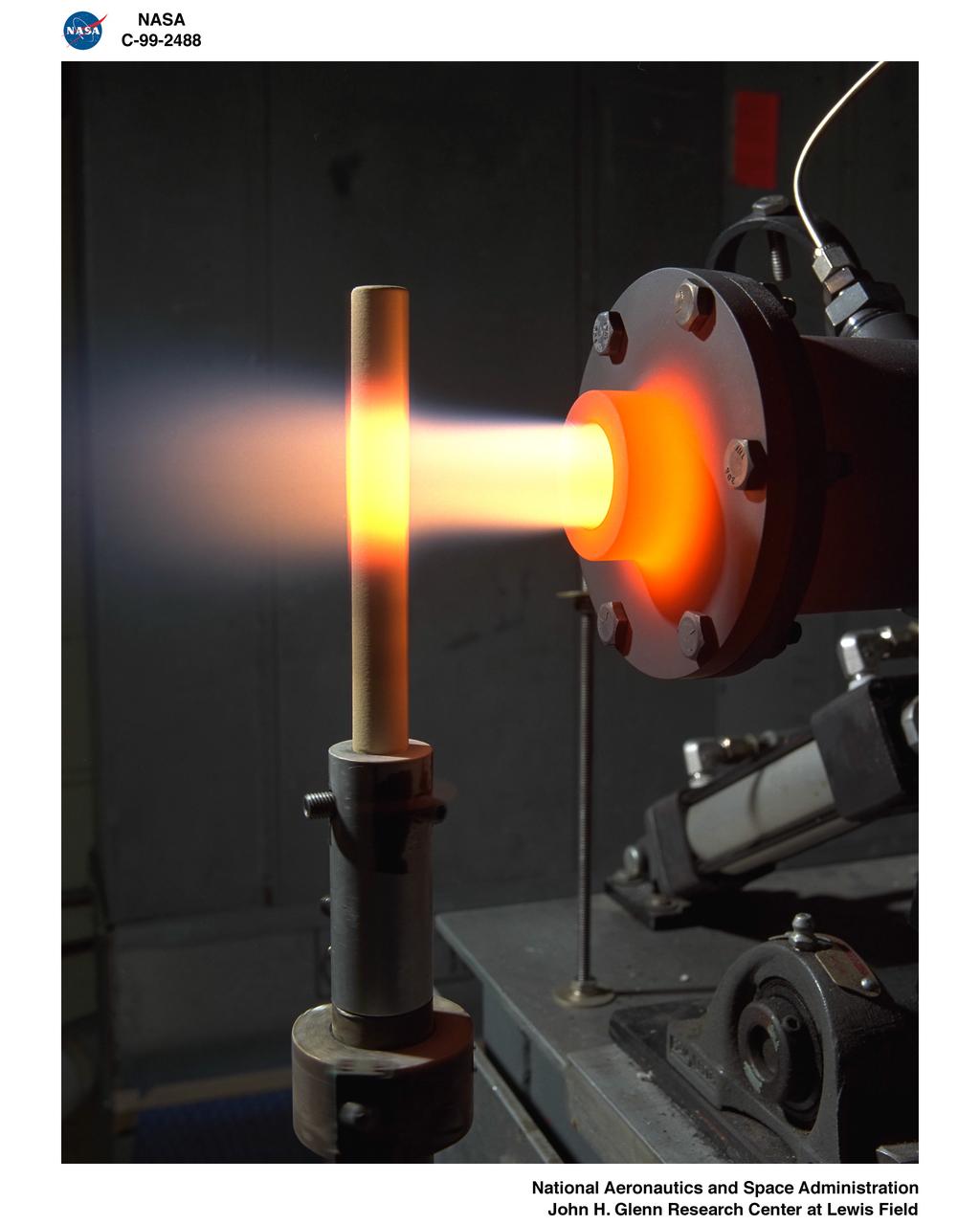
Burner Rig in the Material and Stresses Building
SHIIVER (Structural Heat Intercept Insulation Vibration Evaluation Rig) is a cryogenic test tank developed to evaluate heat intercept concepts. It arrived at Marshall Space Flight Center on August 10, 2017. The tank will receive heat sensors and spray-on foam insulation before making its way to Plum Brook station for further insulation and testing.
SHIIVER (Structural Heat Intercept Insulation Vibration Evaluation Rig)
SHIIVER (Structural Heat Intercept Insulation Vibration Evaluation Rig) is a cryogenic test tank developed to evaluate heat intercept concepts. It arrived at Marshall Space Flight Center on August 10, 2017. The tank will receive heat sensors and spray-on foam insulation before making its way to Plum Brook station for further insulation and testing.SHIIVER Tank Arrives at NASA’s Marshall Center for Spray-On Foam Insulation
SHIIVER (Structural Heat Intercept Insulation Vibration Evaluation Rig)
SHIIVER (Structural Heat Intercept Insulation Vibration Evaluation Rig) is a cryogenic test tank developed to evaluate heat intercept concepts. It arrived at Marshall Space Flight Center on August 10, 2017. The tank will receive heat sensors and spray-on foam insulation before making its way to Plum Brook station for further insulation and testing.
SHIIVER (Structural Heat Intercept Insulation Vibration Evaluation Rig)
SHIIVER Tank Arrives at NASA’s Marshall Center for Spray-On Foam InsulationSHIIVER (Structural Heat Intercept Insulation Vibration Evaluation Rig) is a cryogenic test tank developed to evaluate heat intercept concepts. It arrived at Marshall Space Flight Center on August 10, 2017. The tank will receive heat sensors and spray-on foam insulation before making its way to Plum Brook station for further insulation and testing.
SHIIVER (Structural Heat Intercept Insulation Vibration Evaluation Rig)
An engineer examines the Coherent Turbulence Rig in the Engine Research Building at the National Aeronautics and Space Administration (NASA) Lewis Research Center. Coherent turbulence occurs when waves of uniform size and alignment are present in airflow. Researchers at NASA Lewis were interested in determining the relation between the size of the waves and their heat transfer properties.    The massive 4.25-acre Engine Research Building contains dozens of test cells, test stands, and altitude chambers. A powerful a collection of compressors and exhausters located in the central portion of the basement provides process air and exhaust for these test areas. This system is connected to similar process air systems in the laboratory’s other large test facilities. The Central Control Room coordinates this activity and communicates with the local utilities.
Coherent Turbulence Rig in the Engine Research Building
Juno testing in Glenn Extreme Environments Rig, GEER Laboratory.  Juno is a solar-powered NASA spacecraft that spans the width of a basketball court and makes long, looping orbits around giant planet Jupiter
GRC-2022-C-00970
Various Oil-Free Turbomachinery Hardware and Rigs - thrust bearing rig
GRC-2003-C-01427
Various Oil-Free Turbomachinery Hardware and Rigs - bushing rig
GRC-2003-C-01424
BURNER RIG TESTS IN BOTH HEATING AND COOLING POSITIONS - RADOME CERAMIC MISSILE - EROSION RIG - THERMAL BARRIER COATED SAMPLE
GRC-1999-C-02483
Various Oil-Free Turbomachinery Hardware and Rigs - oil-free turbomachinery demonstration rigs
GRC-2003-C-01451
OVERHEAD VIEW OF NOZZLE ACOUSTIC TEST RIG POWERED LIFT RIG AND ACTIVE NOISE CONTROL FAN
GRC-2001-C-00109
BURNER RIG 126 CELL VANES 1 HOT 1 COLD -  BURNER RIG 121 CELL BLADES 1 HOT 1 COLD
GRC-1998-C-00270
LASER RIG
This image acquired on May 24, 2010 by NASA Terra spacecraft shows oil from the former Deepwater Horizon rig encroaching upon several of Louisiana wildlife habitats.
Leaking Oil Invades Louisiana Wildlife Habitats
MOLTEN SOLDER DROPLET RIG
GRC-1999-C-00311
ADVANCED SUBSONIC COMBUSTION RIG
GRC-1999-C-00248
DIRECTIONALLY SOLIDIFIED RIG
GRC-1995-C-01372
ADVANCED SUBSONIC COMBUSTION RIG
GRC-1999-C-00249
DYNAMIC SPIN RIG
GRC-2002-C-01897
Burner Rig Laboratory
GRC-2015-C-02889
Traction Rig with researcher and engineer
GRC-2008-C-01449
ADVANCED SUBSONIC COMBUSTION SECTOR RIG
GRC-1998-C-00206
DEMONSTRATION RIGS - CAPSTONE MICROTURBINE CUTAWAY
GRC-2003-C-00301
ION PROPULSION LABORATORIES - HYDROFORMING RIG
GRC-2001-C-00377
COMBUSTOR LINERS FOR THERMAL GRADIENT RIG
GRC-2000-C-01847
A 1-foot long stator blade with a thermal coating subjected to intense heat in order to test its strength at the National Aeronautics and Space Administration (NASA) Lewis Research Center. Lewis researchers sought to determine optimal types of ceramic coatings to increase the durability of metals. The research was primarily intended to support the design of stator blades for high-performance axial-flow compressor and turbofan engines. The coatings reduced the temperature of the metal and the amount of required cooling.       As engines became more and more sophisticated, compressor blades were required to withstand higher and higher temperatures. Lewis researchers developed a dual-layer thermal-barrier coating that could be applied to turbine vanes and blades and combustion liners. This new sprayable thermal-barrier coating was evaluated for its durability, strength, fatigue, and aerodynamic penalties.    This hot-gas rig fired the scorching gas at the leading edge of a test blade. The blade was cooled by an internal air flow. The blades were heated at two different velocities during the program. When using Mach 0.3 gases the entire heating and cooling cycle only lasted 30 seconds.  The cycle lasted 60 minutes during tests at Mach 1.
Stator Blade with Thermal Barrier Testing on Hot Gas Rig
PULSED EJECTOR WAVE PROPAGATION TEST RIG
GRC-2001-C-00705
INTERIORS OF FATIGUE LAB - STIRLING RIG #1
GRC-2003-C-02071
Spin Rig Facility with Optical Probe Instrumentation
GRC-2003-C-00217
THERMAL GRADIENT RIG CERAMIC MATRIX COMPOSITE CYLINDERS
GRC-1999-C-02417
DEEP SPACE 1 ION THRUSTER IN GIMBAL RIG
GRC-1998-C-02059
FULLY MAGNETICALLY SUSPENDED SPIN RIG PARTS
GRC-2000-C-01000
Closed-Loop Regenerative Fuel Cell Rig
GRC-2009-C-04806
FULLY MAGNETICALLY SUSPENDED SPIN RIG PARTS
GRC-2000-C-01001
Oil-Free Turbomachinery Thrust Bearing Test Rig
GRC-2006-C-00387
INTERIORS OF FATIGUE LAB - TMD RIG #2
GRC-2003-C-02061
Closed-Loop Regenerative Fuel Cell Rig
GRC-2009-C-04808
FULLY MAGNETICALLY SUSPENDED SPIN RIG PARTS
GRC-2000-C-00999
Spin Rig Facility with Optical Probe Instrumentation
GRC-2003-C-00216
RAYLEIGH SCATTERING SET UP ON LARGE NOZZLE RIG
GRC-2002-C-00651
Oil-Free Turbomachinery Thrust Bearing Test Rig
GRC-2006-C-00389
DROPLET COMBUSTION EXPERIMENT DCE DROP RIG
GRC-1998-C-02454
THERMAL GRADIENT RIG CERAMIC MATRIX COMPOSITE CYLINDERS
GRC-1999-C-02419
INTERIORS OF FATIGUE LAB - STIRLING RIG #1
GRC-2003-C-02070
DROPLET COMBUSTION EXPERIMENT DCE DROP RIG
GRC-1998-C-02455
Various Oil-Free Turbomachinery Hardware and Rigs - SE-8 control room
GRC-2003-C-01444
Low Pressure Plasma Thin Film Rig for Thermal and Environmental Barrier Coatings
GRC-2011-C-00389
FAST QUIET EXPERIMENT TEST ON THE MACH 3 BURNER RIG
GRC-1999-C-00907
Oil-Free High-Pressure Journal Bearing Test Rig
GRC-2007-C-01221
Low Pressure Plasma Thin Film Rig for Thermal and Environmental Barrier Coatings
GRC-2011-C-00369
X33 COMBUSTION WARE IGNITION FULL SCALE PROTOYPE TEST RIG
GRC-1998-C-01289
X33 COMBUSTION WARE IGNITION FULL SCALE PROTOYPE TEST RIG
GRC-1998-C-01287
Twin Jet Hardware in the Nozzle Acoustical Test Rig, NATR
GRC-2010-C-02420
Nozzle Acoustic Test Rig (NATR), High Flow Jet Exit 2009
GRC-2009-C-01220
Quare Rig exposed coated and uncoated GRCop-84 sheet specimens
GRC-2004-C-01379
BEARINGS COMPONENT TEST RIG SHAFTING TEST ASSEMBLY WITH SPECIMEN
GRC-1999-C-02252
HIGH TEMP HIGH SPEED TURBINE SEAL TEST RIG
GRC-2002-C-00965
HIGH TEMP HIGH SPEED TURBINE SEAL TEST RIG
GRC-2002-C-00969
Tour of the Umbilical Test Rig and the Crew Exploration Vehicle (CEV) Test Area
GRC-2009-C-01019
Nozzle Acoustic Test Rig (NATR), High Flow Jet Exit 2009
GRC-2009-C-01210
Increased Fidelity Actuator Hardware Installation, 2-Axis Rig
GRC-2010-C-01024
HIGH TEMPERATURE MAGNETIC BEARING TEST RIG AT 1000 DEGREES FARENHEIDT
GRC-2002-C-01190
CERAMIC MATRIX COMPOSITE CYLINDER FOR THERMAL GRADIENT RIG WITH INSTRUMENTATION
GRC-2000-C-00122
Nozzle Acoustic Test Rig (NATR), High Flow Jet Exit 2009
GRC-2009-C-01209
Low Pressure Plasma Thin Film Rig for Thermal and Environmental Barrier Coatings
GRC-2011-C-00386
Glenn Extreme Environments Rig, GEER, Test Chamber, recreate Venus conditions on Earth, photos of insulation construction progress
GRC-2013-C-04629
Glenn Extreme Environments Rig, GEER, Test Chamber, recreate Venus conditions on Earth, photos of insulation construction progress
GRC-2013-C-04622
Glenn Extreme Environments Rig, GEER, Test Chamber, recreate Venus conditions on Earth, photos of insulation construction progress
GRC-2013-C-04631
Historical Baseline Blade Set (F31/A31) Installed on the Open Rotor Propulsion Rig in the 9x15 Wind Tunnel
GRC-2010-C-03457
BURNER RIG TESTS IN BOTH HEATING AND COOLING POSITIONS - TITANIUM ALUMINIDE ALLOY TEST - HOT
GRC-1999-C-02482
ROCKET BASED COMBINED CYCLE  -  RBCC  -  RIG 3.1 MODEL INSTALLED IN 10X10 FOOT SUPERSONIC WIND TUNNEL TEST SECTION
GRC-2000-C-00707
DROPLET COMBUSTION EXPERIMENT DCE DROP RIG SUB COMPONENTS IGNITOR FUEL DISPENSER MOTOR 2 PC BOARDS
GRC-1998-C-02460
Glenn Extreme Environments Rig, GEER, Test Chamber used to create Venus Conditions on Earth
GRC-2013-C-04419
Twin Jet Model, Nozzle Acoustic Test Rig, NATR, Aeroacoustic Propulsion Laboratory, AAPL
GRC-2013-C-01260
The Plasma Spray-Physical Vapor Deposition, PS-PVD, Rig, Coatings for Next-Generation Turbine Components, Creating Efficient Engines
GRC-2015-C-00249
BURNER RIG TESTS IN BOTH HEATING AND COOLING POSITIONS - CERAMIC MISSILE RADOME TEST
GRC-1999-C-02486
Glenn Extreme Environments Rig, GEER, Test Chamber used to create Venus Conditions on Earth
GRC-2013-C-04415
ROCKET BASED COMBINED CYCLE  -  RBCC  -  RIG 3.1 MODEL INSTALLED IN 10X10 FOOT SUPERSONIC WIND TUNNEL TEST SECTION
GRC-2000-C-00683
DROPLET COMBUSTION EXPERIMENT DCE DROP RIG SUB COMPONENTS IGNITOR FUEL DISPENSER MOTOR 2 PC BOARDS
GRC-1998-C-02459
DROPLET COMBUSTION EXPERIMENT DCE DROP RIG SUB COMPONENTS IGNITOR FUEL DISPENSER MOTOR 2 PC BOARDS
GRC-1998-C-02456
Historical Baseline Blade Set (F31/A31) Installed on the Open Rotor Propulsion Rig in the 9x15 Wind Tunnel
GRC-2010-C-03453