
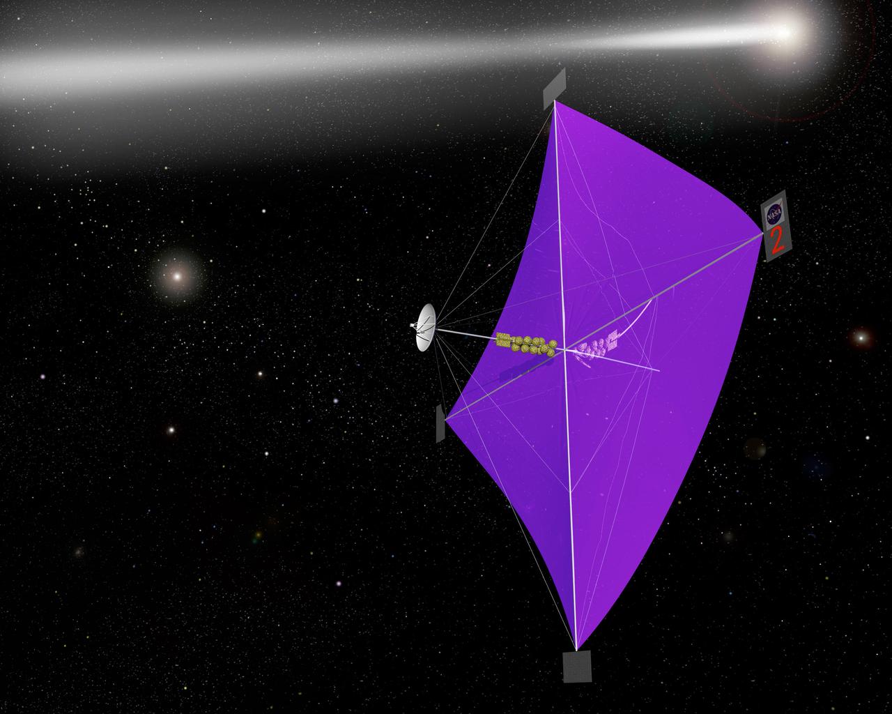
This artist’s concept shows the Advanced Composite Solar Sail System spacecraft sailing in space using the energy of the Sun.
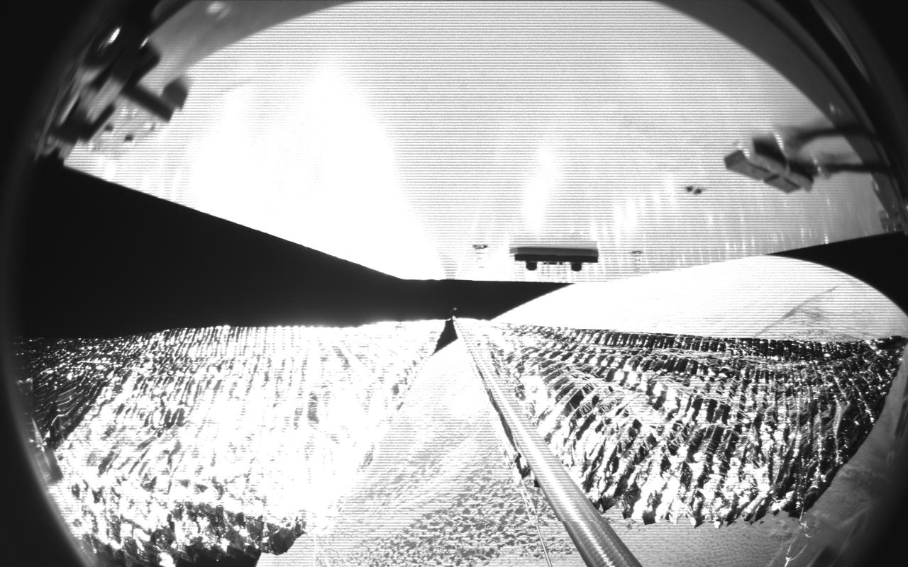
Four cameras aboard the Advanced Composite Solar Sail System spacecraft show the four reflective sail quadrants supported by composite booms. The booms are mounted at right angles and the spacecraft’s solar panel is rectangular, but lines appear distorted because of the wide-angle camera field of view. View from a black-and-white wide-angle camera aboard the Advanced Composite Solar Sail System taken during sail unfurling in low Earth orbit. The spacecraft has four such cameras, centrally located aboard the spacecraft. Here, reflective sail quadrants supported by composite booms are seen when the booms are partially extended and the sail quadrants are not taut. At the top of the photo is the back surface of one of the spacecraft’s solar panels. On the lower right Earth is seen below.
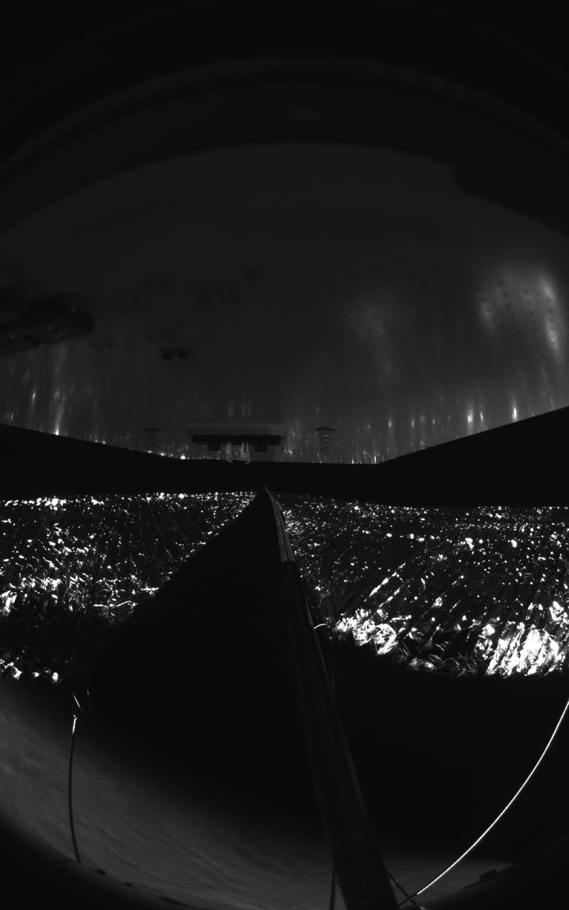
Four cameras aboard the Advanced Composite Solar Sail System spacecraft show the four reflective sail quadrants supported by composite booms. The booms are mounted at right angles and the spacecraft’s solar panel is rectangular, but lines appear distorted because of the wide-angle camera field of view. View from a black-and-white wide-angle camera aboard the Advanced Composite Solar Sail System taken during sail unfurling in low Earth orbit. The spacecraft has four such cameras, centrally located aboard the spacecraft. Here, reflective sail quadrants supported by composite booms are seen when the booms are partially extended and the sail quadrants are not taut. At the top of the photo is the back surface of one of the spacecraft’s solar panels. On the lower left Earth’s limb is seen below.
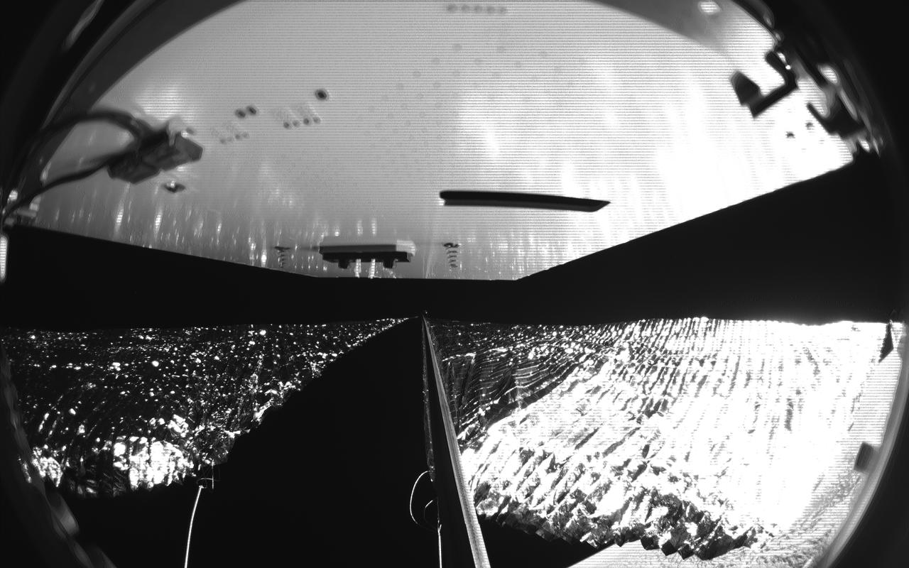
Four cameras aboard the Advanced Composite Solar Sail System spacecraft show the four reflective sail quadrants supported by composite booms. The booms are mounted at right angles and the spacecraft’s solar panel is rectangular, but lines appear distorted because of the wide-angle camera field of view. View from a black-and-white wide-angle camera aboard the Advanced Composite Solar Sail System taken during sail unfurling in low Earth orbit. The spacecraft has four such cameras, centrally located aboard the spacecraft. Here, reflective sail quadrants supported by composite booms are seen when the booms are partially extended and the sail quadrants are not taut. At the top of the photo is the back surface of one of the spacecraft’s solar panels. On the lower right Earth is seen below.

An artist’s concept of NASA’s Advanced Composite Solar Sail System spacecraft in orbit as seen from directly above the spacecraft looking down at Earth below.
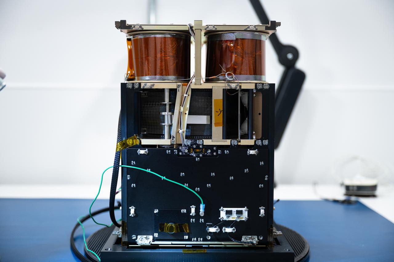
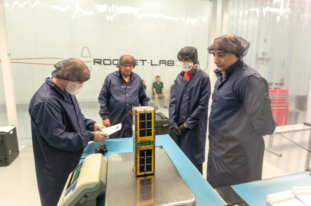
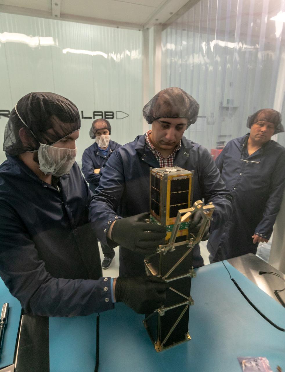
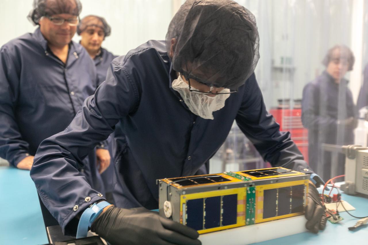
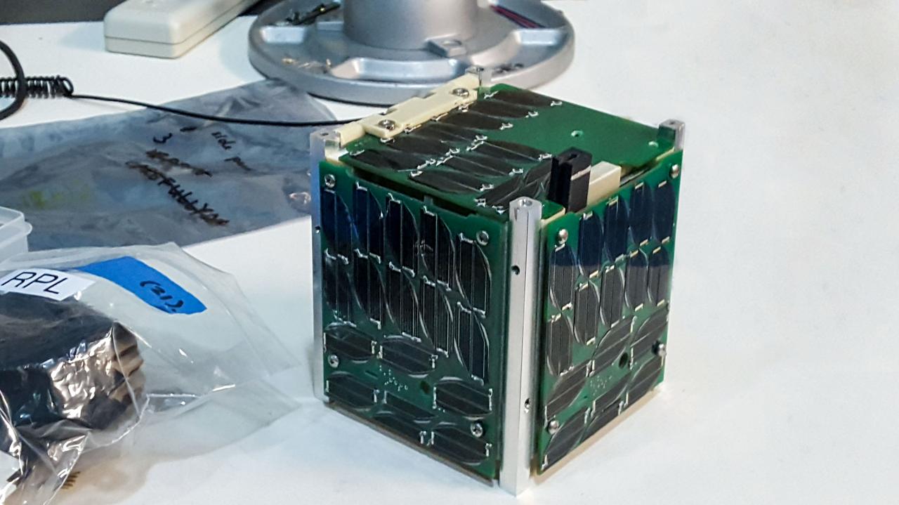
Electric Sail 6U CubeSat Testbed Article with Tether Mockup
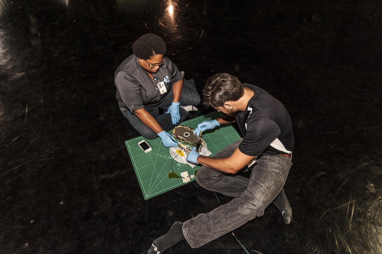
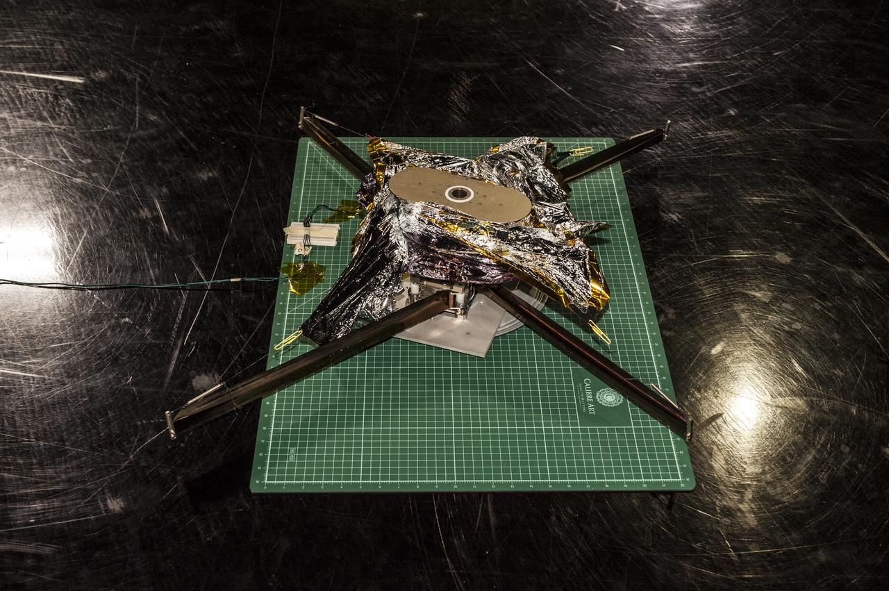
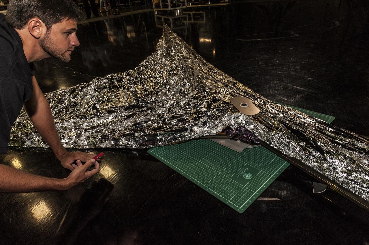
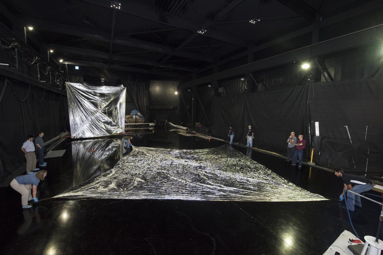
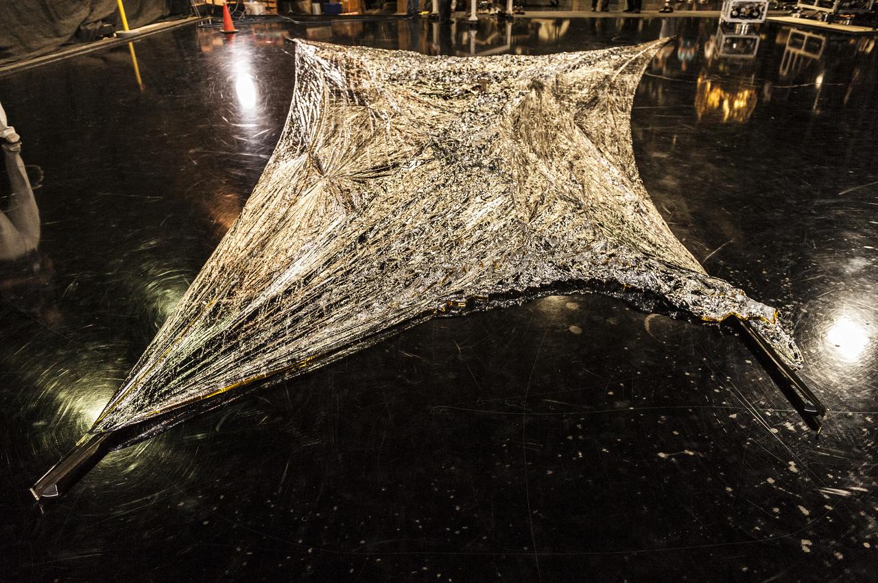
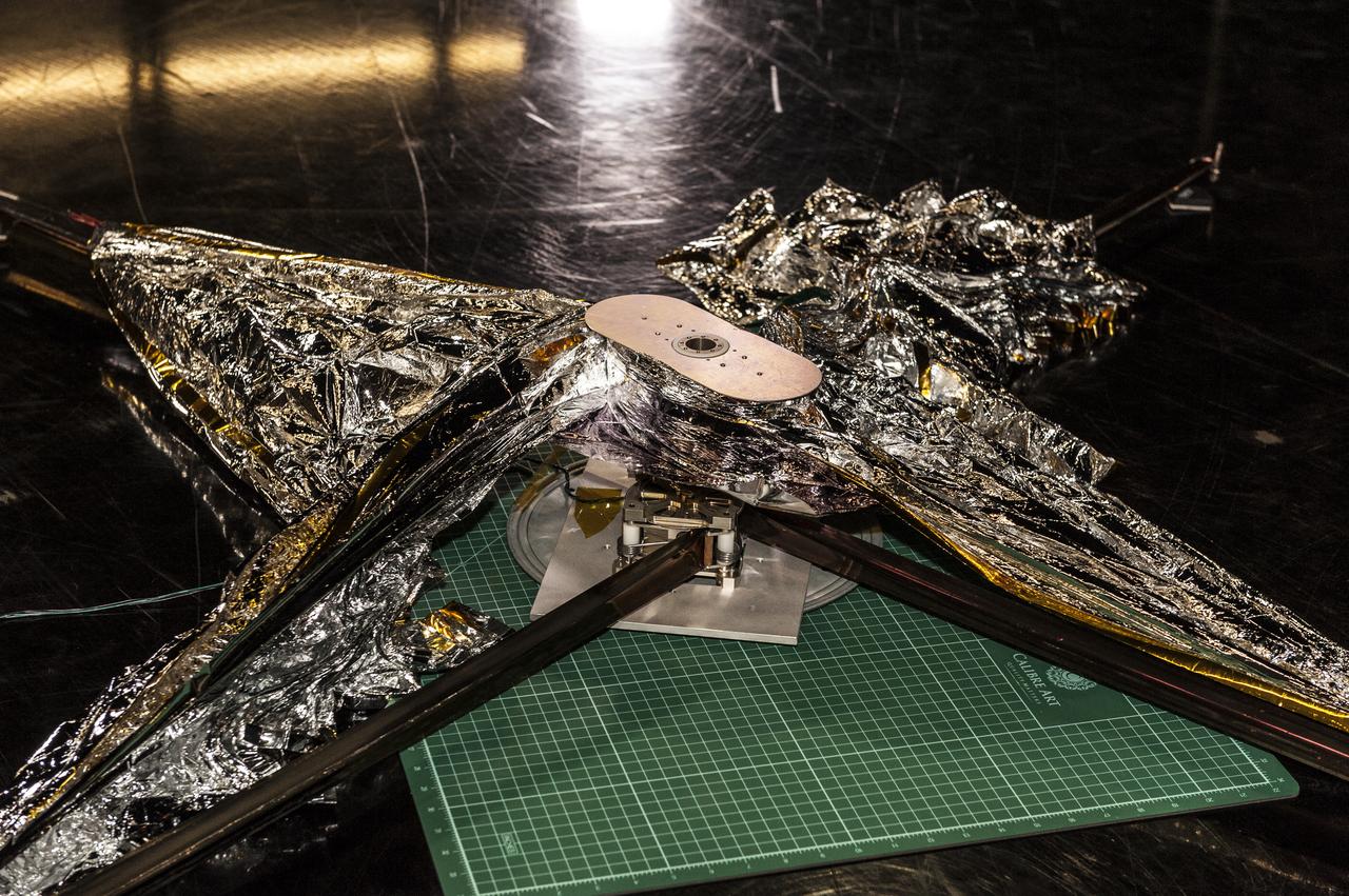
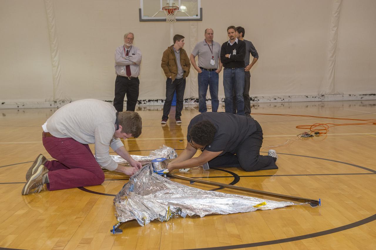
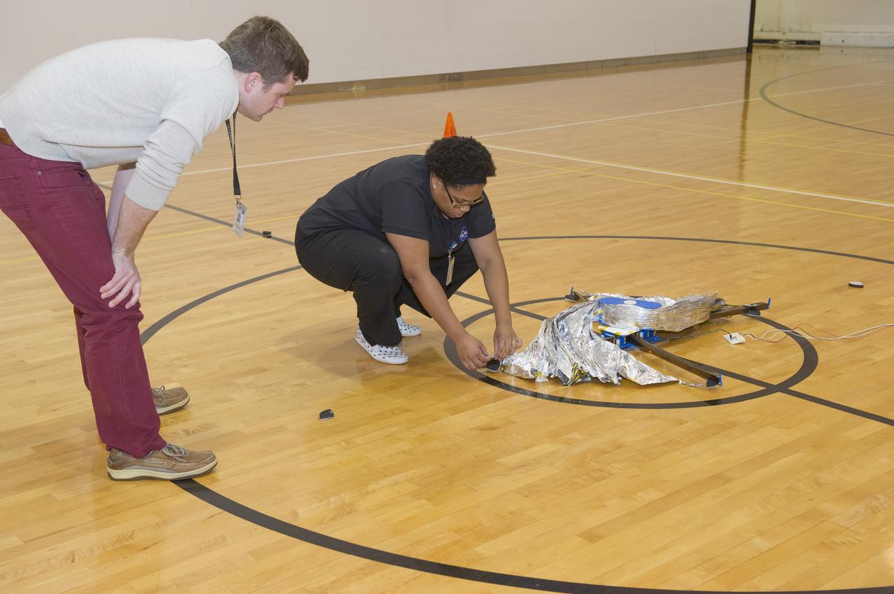
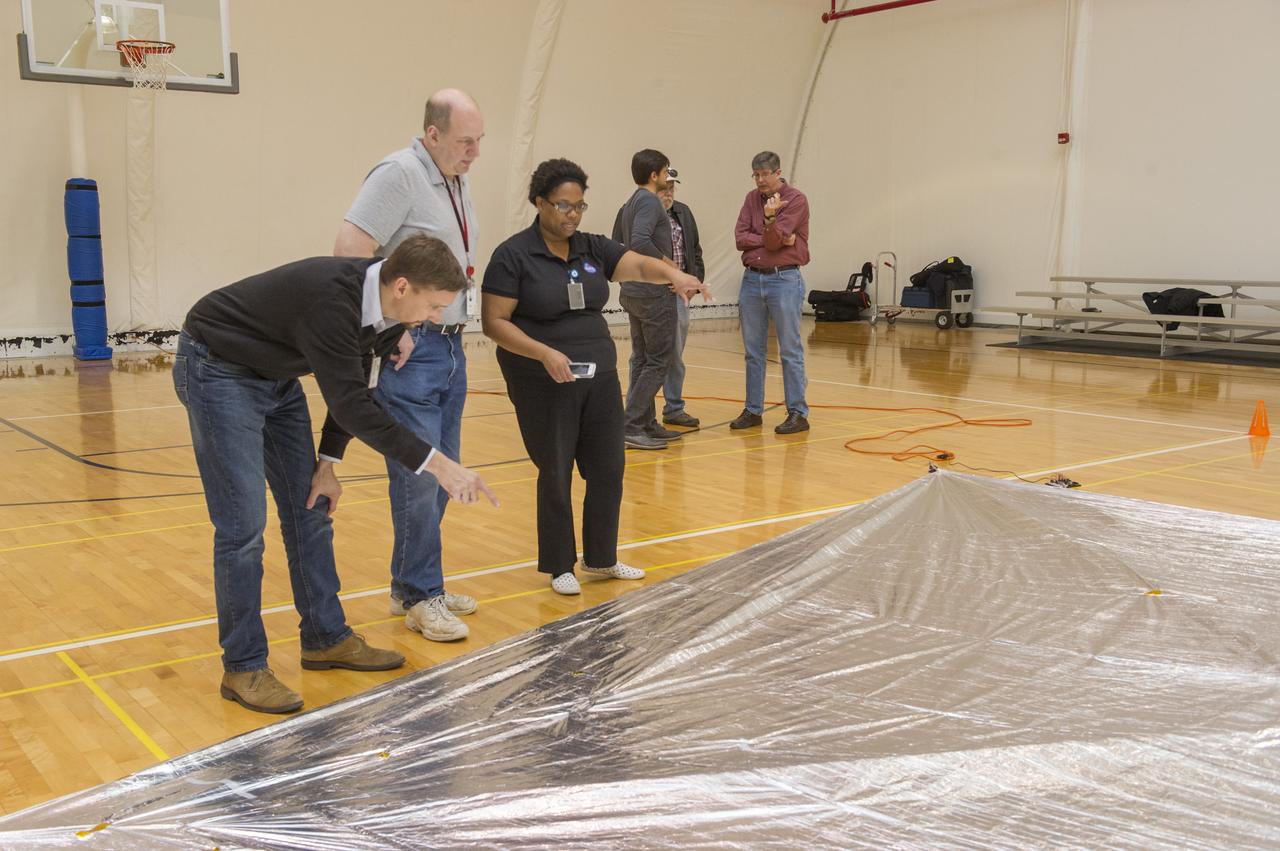
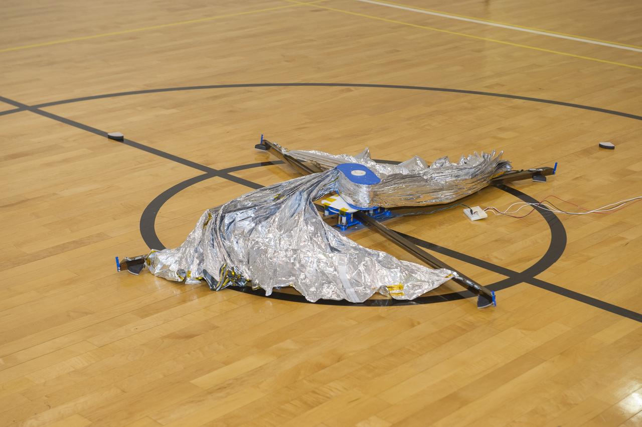
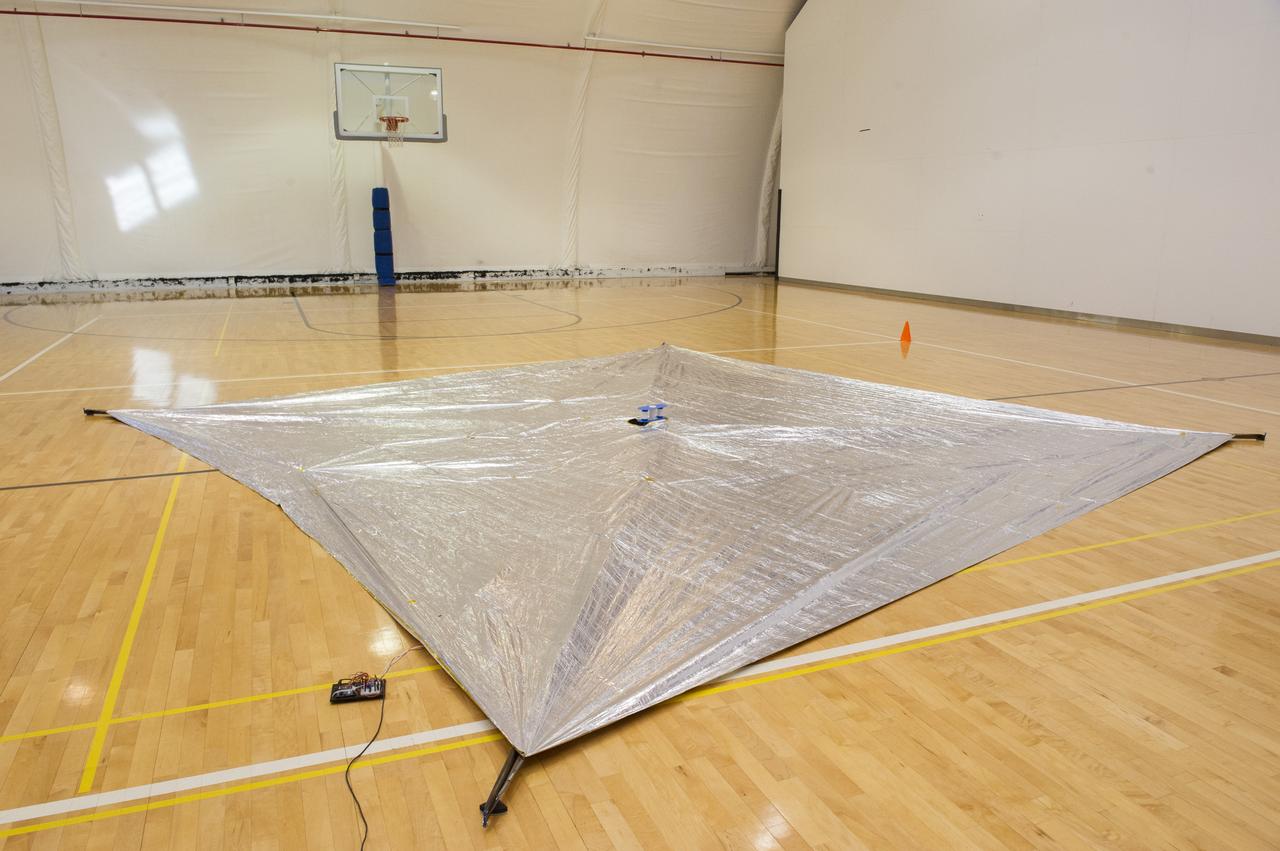
NEAR EARTH ASTEROID (NEA) SAIL TEAM PERFORMING A DEPLOYMENT OF THE FLIGHT-LIKE ENGINEERING DEVELOPMENT UNIT SOLAR SAIL. THE SAIL WAS MANUFACTURED AT NEXOLVE (HSV, AL) AND DEPLOYED FOR THE FIRST TIME AT MSFC ON AUGUST 4TH, 2016
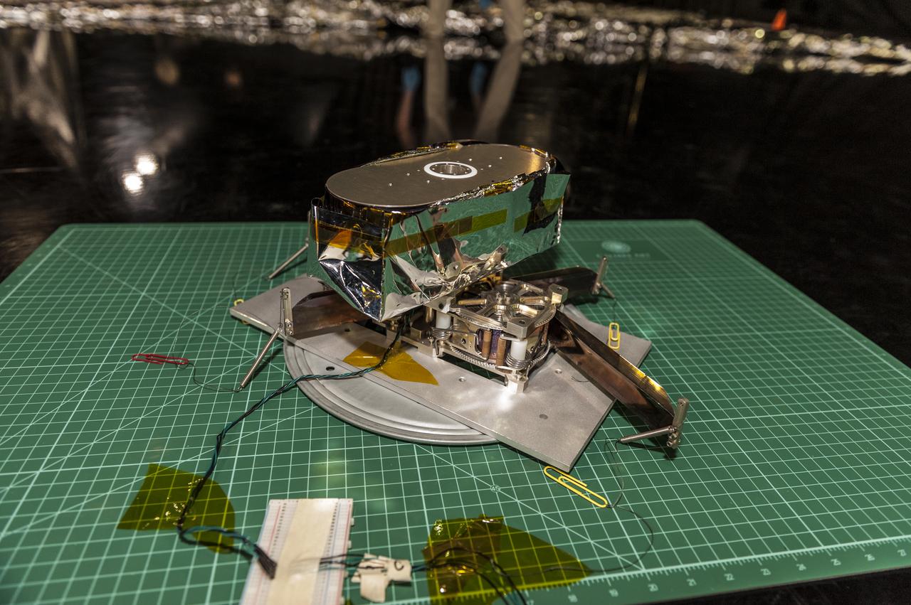
NEAR EARTH ASTEROID (NEA) SAIL TEAM PERFORMING A DEPLOYMENT OF THE FLIGHT-LIKE ENGINEERING DEVELOPMENT UNIT SOLAR SAIL. THE SAIL WAS MANUFACTURED AT NEXOLVE (HSV, AL) AND DEPLOYED FOR THE FIRST TIME AT MSFC ON AUGUST 4TH, 2016
NEAR EARTH ASTEROID (NEA) SAIL TEAM PERFORMING A DEPLOYMENT OF THE FLIGHT-LIKE ENGINEERING DEVELOPMENT UNIT SOLAR SAIL. THE SAIL WAS MANUFACTURED AT NEXOLVE (HSV, AL) AND DEPLOYED FOR THE FIRST TIME AT MSFC ON AUGUST 4TH, 2016
NEAR EARTH ASTEROID (NEA) SAIL TEAM PERFORMING A DEPLOYMENT OF THE FLIGHT-LIKE ENGINEERING DEVELOPMENT UNIT SOLAR SAIL. THE SAIL WAS MANUFACTURED AT NEXOLVE (HSV, AL) AND DEPLOYED FOR THE FIRST TIME AT MSFC ON AUGUST 4TH, 2016
NEAR EARTH ASTEROID (NEA) SAIL TEAM PERFORMING A DEPLOYMENT OF THE FLIGHT-LIKE ENGINEERING DEVELOPMENT UNIT SOLAR SAIL. THE SAIL WAS MANUFACTURED AT NEXOLVE (HSV, AL) AND DEPLOYED FOR THE FIRST TIME AT MSFC ON AUGUST 4TH, 2016
NEAR EARTH ASTEROID (NEA) SAIL TEAM PERFORMING A DEPLOYMENT OF THE FLIGHT-LIKE ENGINEERING DEVELOPMENT UNIT SOLAR SAIL. THE SAIL WAS MANUFACTURED AT NEXOLVE (HSV, AL) AND DEPLOYED FOR THE FIRST TIME AT MSFC ON AUGUST 4TH, 2016
NEAR EARTH ASTEROID (NEA) SAIL TEAM PERFORMING A DEPLOYMENT OF THE FLIGHT-LIKE ENGINEERING DEVELOPMENT UNIT SOLAR SAIL. THE SAIL WAS MANUFACTURED AT NEXOLVE (HSV, AL) AND DEPLOYED FOR THE FIRST TIME AT MSFC ON AUGUST 4TH, 2016
NEAR EARTH ASTEROID (NEA) SAIL TEAM PERFORMING A DEPLOYMENT OF THE FLIGHT-LIKE ENGINEERING DEVELOPMENT UNIT SOLAR SAIL. THE SAIL WAS MANUFACTURED AT NEXOLVE (HSV, AL) AND DEPLOYED FOR THE FIRST TIME AT MSFC ON AUGUST 4TH, 2016
NEAR EARTH ASTEROID (NEA) SAIL TEAM PERFORMING A DEPLOYMENT OF THE FLIGHT-LIKE ENGINEERING DEVELOPMENT UNIT SOLAR SAIL. THE SAIL WAS MANUFACTURED AT NEXOLVE (HSV, AL) AND DEPLOYED FOR THE FIRST TIME AT MSFC ON AUGUST 4TH, 2016

NEAR EARTH ASTEROID (NEA) SAIL TEAM PERFORMING A DEPLOYMENT OF THE FLIGHT-LIKE ENGINEERING DEVELOPMENT UNIT SOLAR SAIL. THE SAIL WAS MANUFACTURED AT NEXOLVE (HSV, AL) AND DEPLOYED FOR THE FIRST TIME AT MSFC ON AUGUST 4TH, 2016
NEAR EARTH ASTEROID (NEA) SAIL TEAM PERFORMING A DEPLOYMENT OF THE FLIGHT-LIKE ENGINEERING DEVELOPMENT UNIT SOLAR SAIL. THE SAIL WAS MANUFACTURED AT NEXOLVE (HSV, AL) AND DEPLOYED FOR THE FIRST TIME AT MSFC ON AUGUST 4TH, 2016
NEAR EARTH ASTEROID (NEA) SAIL TEAM PERFORMING A DEPLOYMENT OF THE FLIGHT-LIKE ENGINEERING DEVELOPMENT UNIT SOLAR SAIL. THE SAIL WAS MANUFACTURED AT NEXOLVE (HSV, AL) AND DEPLOYED FOR THE FIRST TIME AT MSFC ON AUGUST 4TH, 2016
NEAR EARTH ASTEROID (NEA) SAIL TEAM PERFORMING A DEPLOYMENT OF THE FLIGHT-LIKE ENGINEERING DEVELOPMENT UNIT SOLAR SAIL. THE SAIL WAS MANUFACTURED AT NEXOLVE (HSV, AL) AND DEPLOYED FOR THE FIRST TIME AT MSFC ON AUGUST 4TH, 2016
NEAR EARTH ASTEROID (NEA) SAIL TEAM PERFORMING A DEPLOYMENT OF THE FLIGHT-LIKE ENGINEERING DEVELOPMENT UNIT SOLAR SAIL. THE SAIL WAS MANUFACTURED AT NEXOLVE (HSV, AL) AND DEPLOYED FOR THE FIRST TIME AT MSFC ON AUGUST 4TH, 2016
NEAR EARTH ASTEROID (NEA) SAIL TEAM PERFORMING A DEPLOYMENT OF THE FLIGHT-LIKE ENGINEERING DEVELOPMENT UNIT SOLAR SAIL. THE SAIL WAS MANUFACTURED AT NEXOLVE (HSV, AL) AND DEPLOYED FOR THE FIRST TIME AT MSFC ON AUGUST 4TH, 2016

An artist’s concept of NASA’s Advanced Composite Solar Sail System spacecraft in Earth orbit.
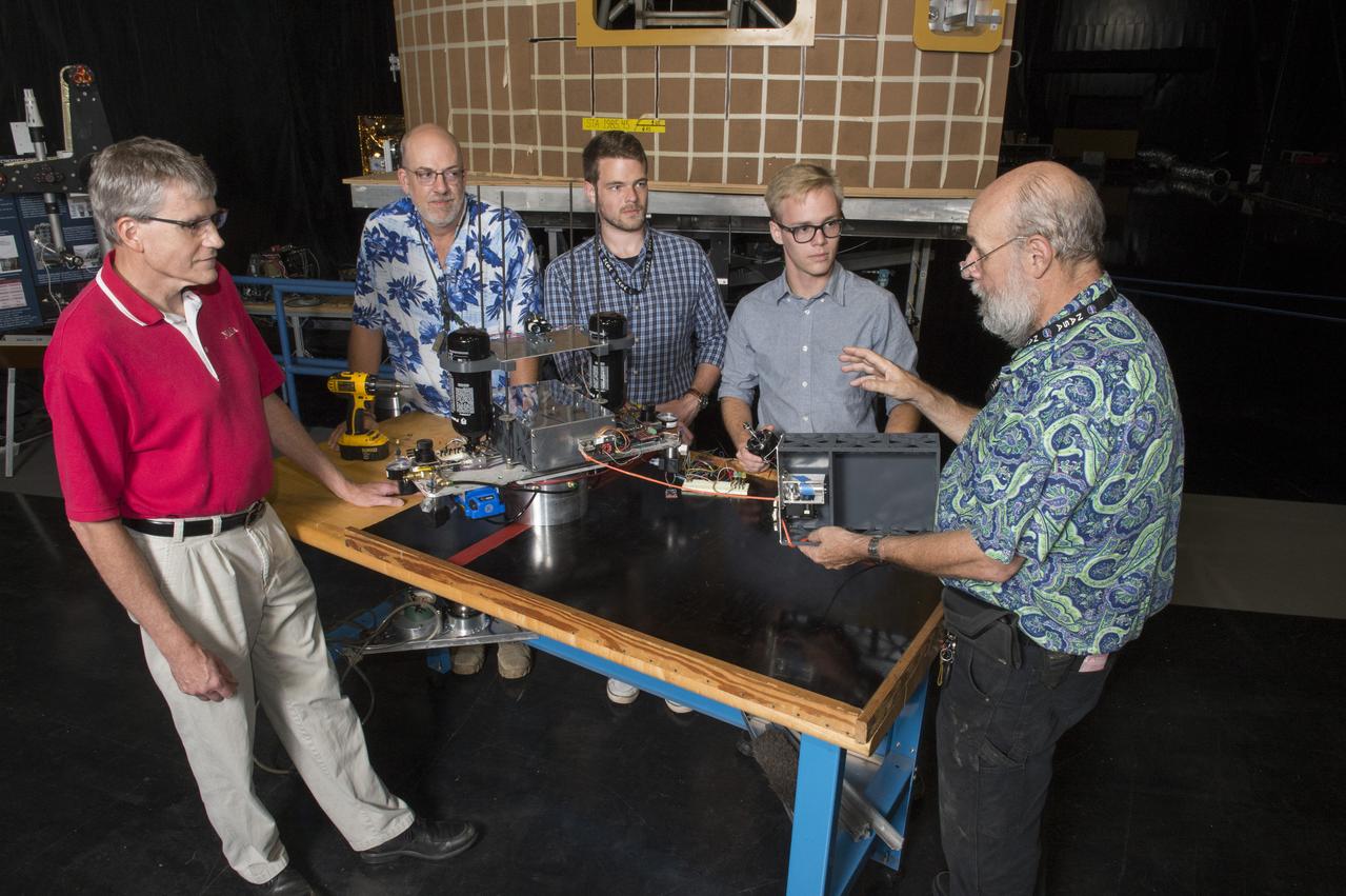
Electric Sail (E-Sail) Tether Team Discusses 6U CubeSat Test Article and Tether Deployment System (Right to left: Tom Bryan, Davis Hunter (student intern), Jonathan MacArthur (student intern), Charles Cowen, Mike Tinker)
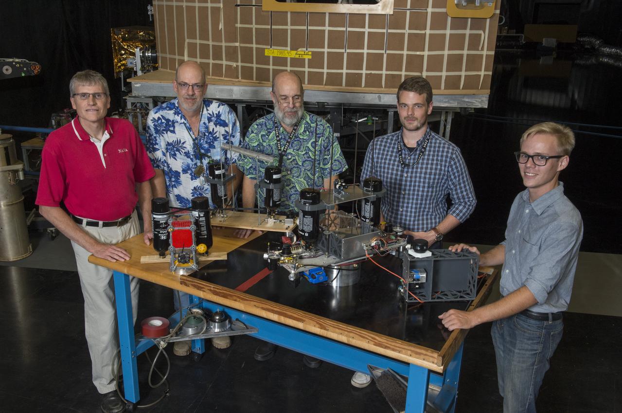
Electric Sail (E-Sail) Tether Team with 6U CubeSat Prototypes and Current Version of Tether Deployer Test Article, (Right to left: Tom Bryan, Davis Hunter (student intern), Jonathan MacArthur (student intern), Charles Cowen, Mike Tinker)
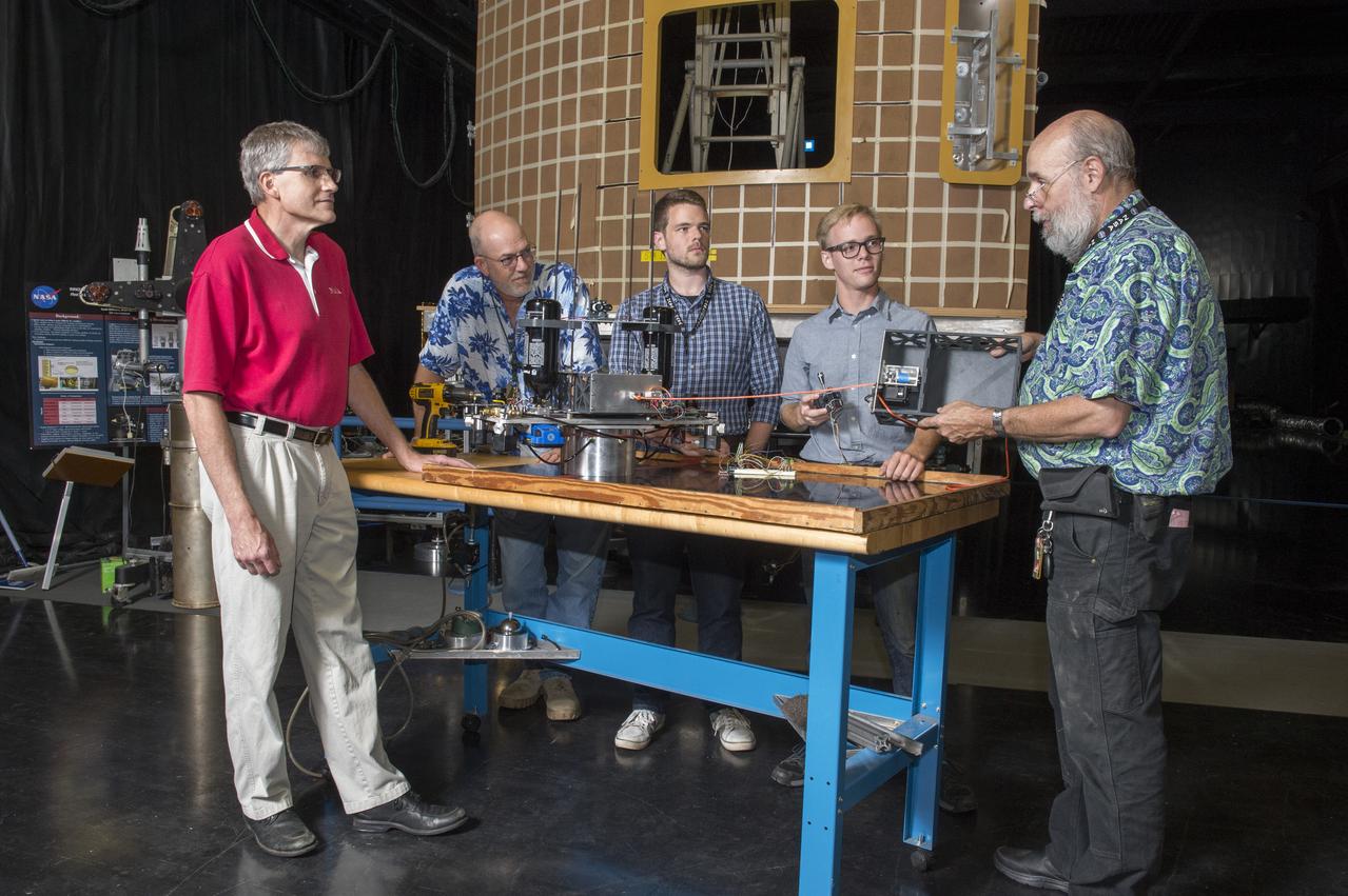
Electric Sail (E-Sail) Tether Team Discusses 6U CubeSat Test Article and Tether Deployment System (Right to left: Tom Bryan, Davis Hunter (student intern), Jonathan MacArthur (student intern), Charles Cowen, Mike Tinker)

An artist's concept of NASA's Advanced Composite Solar Sail System spacecraft in orbit as the Sun crests Earth's horizon.

An artist’s concept of NASA’s Advanced Composite Solar Sail System spacecraft in Earth orbit with the Sun in the background.
Sailing to White Boat
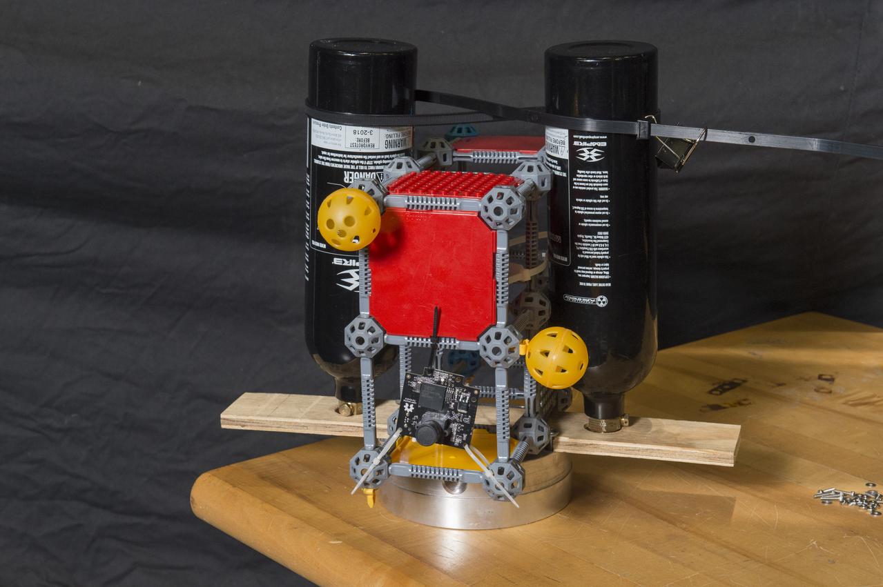
First Generation Agile Engineering Prototype of Electric Sail 6U CubeSat Testbed Article

An artist’s concept of NASA’s Advanced Composite Solar Sail System spacecraft orbiting Earth, showing a configuration with solar arrays deployed and the sails and the booms stowed.

NASA’s Advanced Composite Solar Sail System is seen orbiting Earth in this 13-second exposure photograph, Monday, Sept. 2, 2024, from Arlington, Virginia. The mission team confirmed the spacecraft’s unique composite boom system unfurled its reflective sail on Thursday, accomplishing a critical milestone in the agency’s demonstration of next-generation solar sail technology that will allow small spacecraft to “sail on sunlight.” Just as a sailboat is powered by wind in a sail, a spacecraft can use the pressure of sunlight on a solar sail for propulsion. This technology demonstration serves as a pathfinder for future missions powered by solar sail technology. Photo Credit: (NASA/Bill Ingalls)
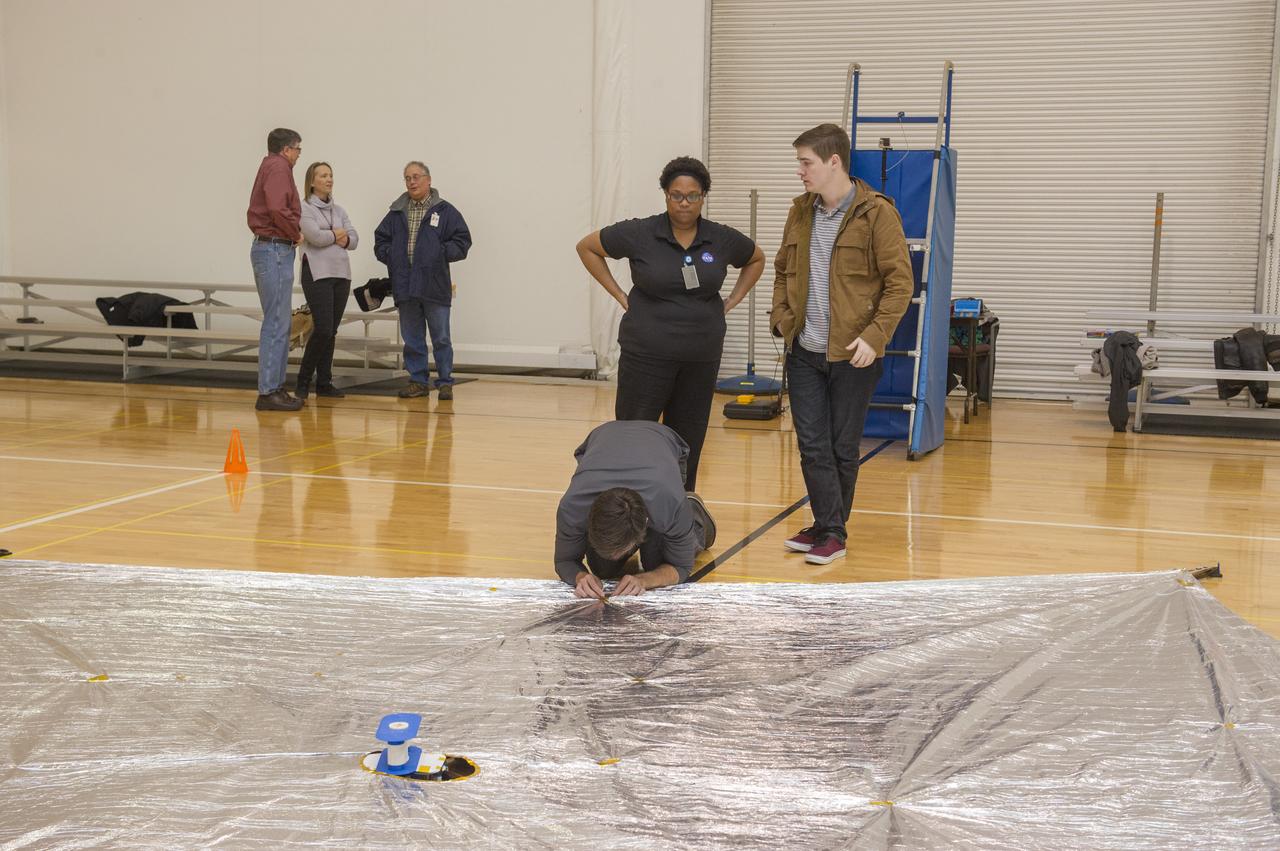
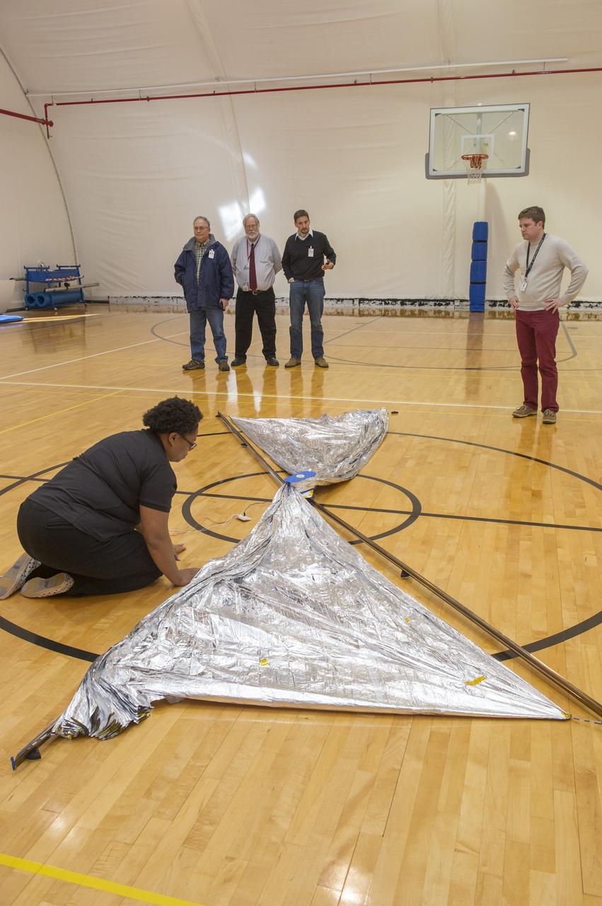
TIFFANY LOCKETT OVERSEES THE HALF SCALE (36 SQUARE METERS) ENGINEERING DEVELOPMENT UNIT (EDU) SOLAR SAIL DEPLOYMENT DEMONSTRATION IN PREPARATION FOR FULL SCALE EDU (86 SQUARE METERS) DEPLOYMENT IN APRIL, 2016. DETAILS OF RIPS AND HOLES IN SOLAR SAIL FABRIC.
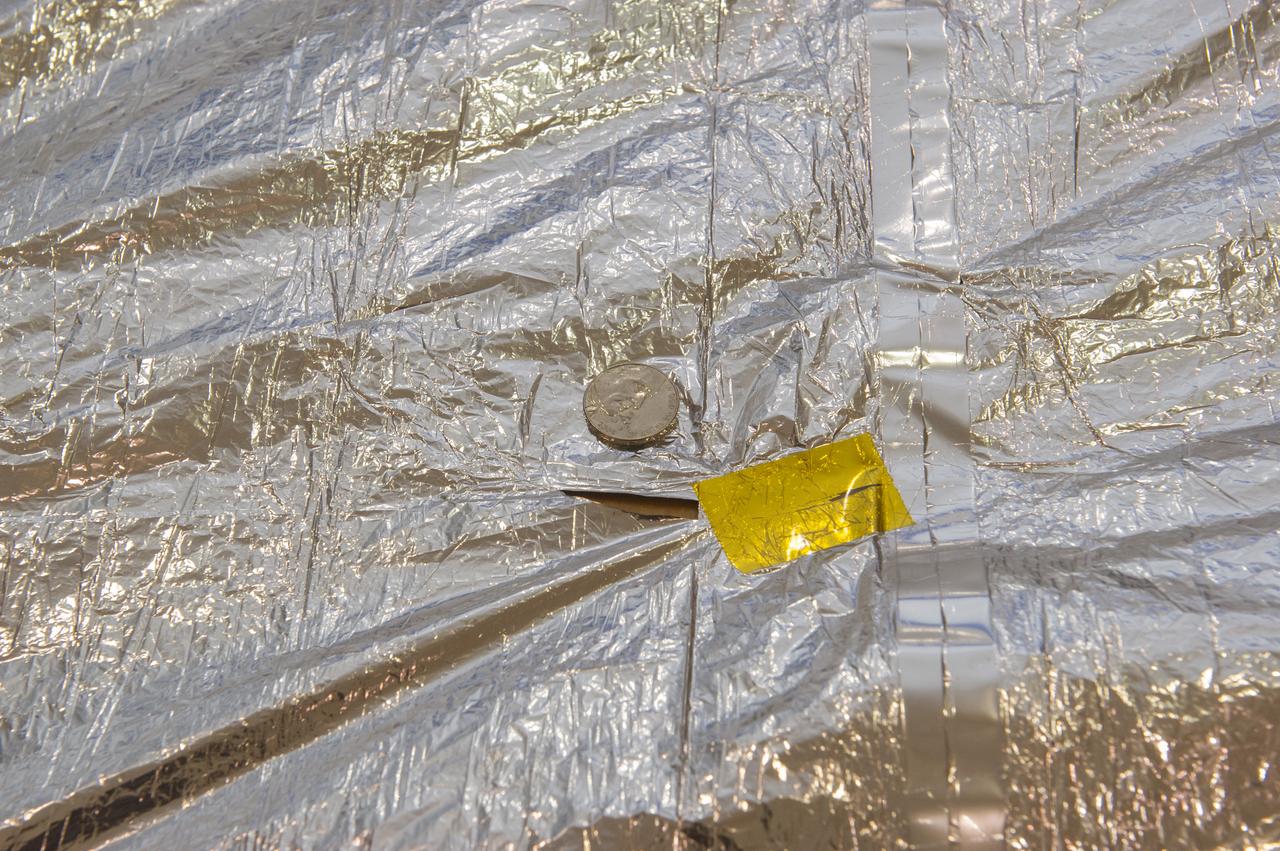
TIFFANY LOCKETT OVERSEES THE HALF SCALE (36 SQUARE METERS) ENGINEERING DEVELOPMENT UNIT (EDU) SOLAR SAIL DEPLOYMENT DEMONSTRATION IN PREPARATION FOR FULL SCALE EDU (86 SQUARE METERS) DEPLOYMENT IN APRIL, 2016. DETAILS OF RIPS AND HOLES IN SOLAR SAIL FABRIC.
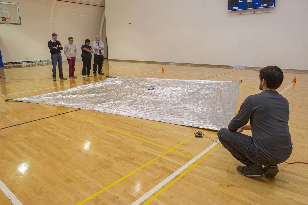
TIFFANY LOCKETT OVERSEES THE HALF SCALE (36 SQUARE METERS) ENGINEERING DEVELOPMENT UNIT (EDU) SOLAR SAIL DEPLOYMENT DEMONSTRATION IN PREPARATION FOR FULL SCALE EDU (86 SQUARE METERS) DEPLOYMENT IN APRIL, 2016
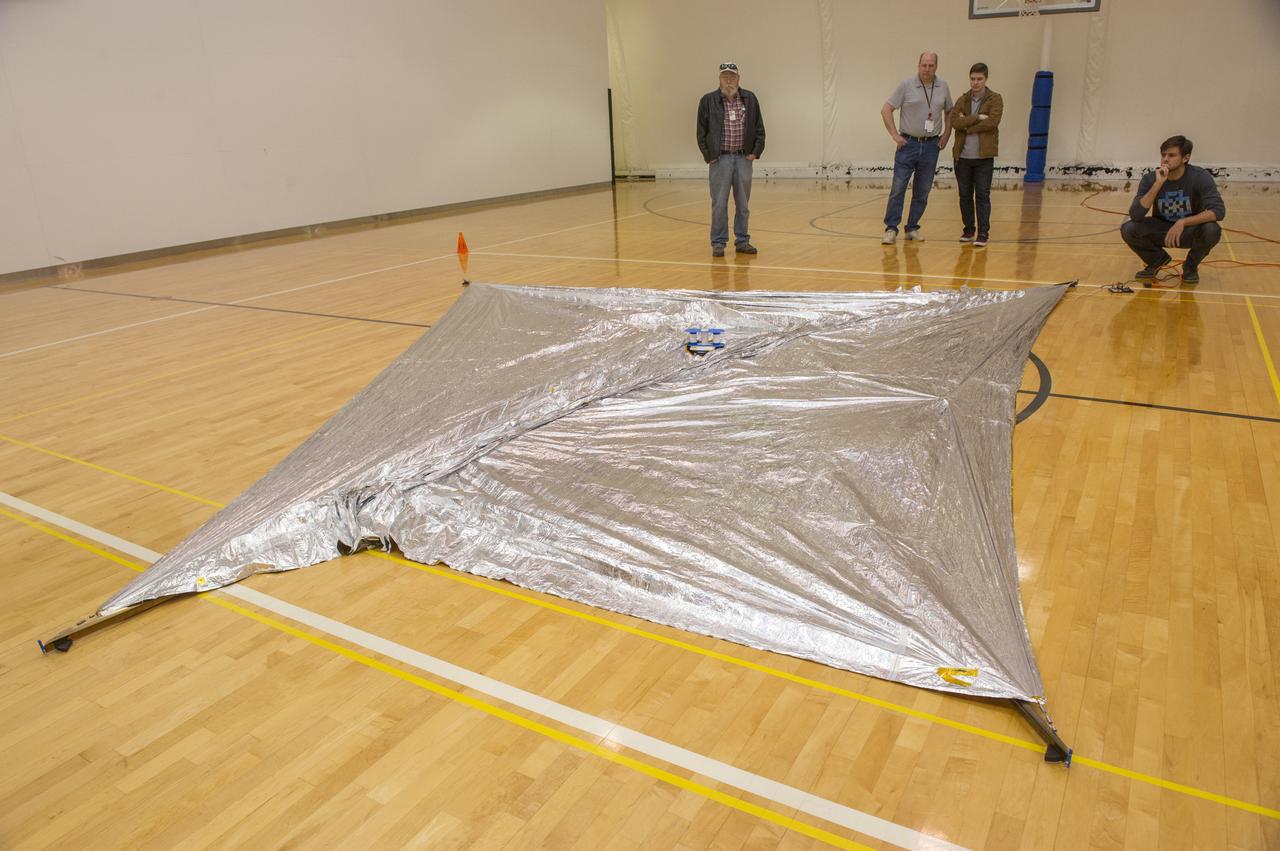
TIFFANY LOCKETT OVERSEES THE HALF SCALE (36 SQUARE METERS) ENGINEERING DEVELOPMENT UNIT (EDU) SOLAR SAIL DEPLOYMENT DEMONSTRATION IN PREPARATION FOR FULL SCALE EDU (86 SQUARE METERS) DEPLOYMENT IN APRIL, 2016
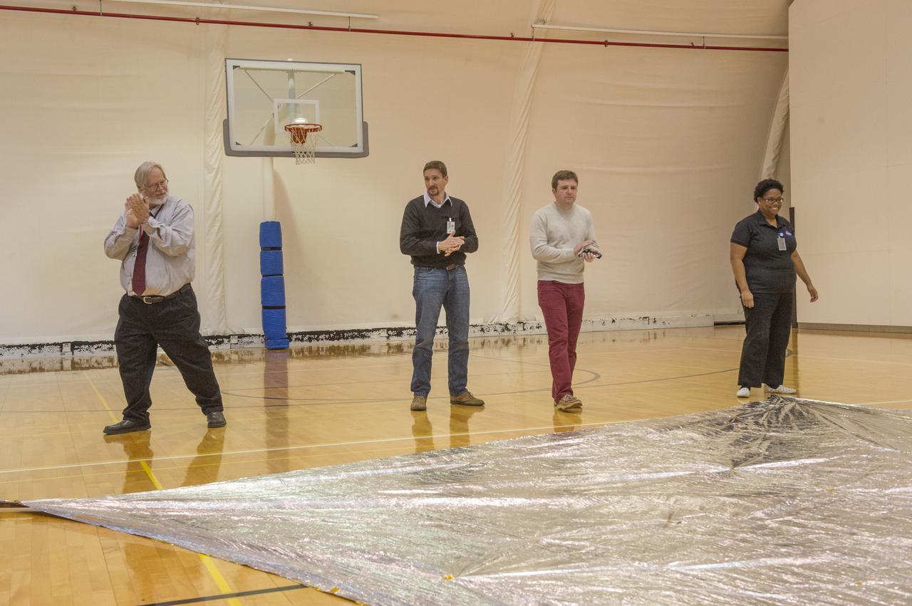
TIFFANY LOCKETT OVERSEES THE HALF SCALE (36 SQUARE METERS) ENGINEERING DEVELOPMENT UNIT (EDU) SOLAR SAIL DEPLOYMENT DEMONSTRATION IN PREPARATION FOR FULL SCALE EDU (86 SQUARE METERS) DEPLOYMENT IN APRIL, 2016
TIFFANY LOCKETT OVERSEES THE HALF SCALE (36 SQUARE METERS) ENGINEERING DEVELOPMENT UNIT (EDU) SOLAR SAIL DEPLOYMENT DEMONSTRATION IN PREPARATION FOR FULL SCALE EDU (86 SQUARE METERS) DEPLOYMENT IN APRIL, 2016
TIFFANY LOCKETT OVERSEES THE HALF SCALE (36 SQUARE METERS) ENGINEERING DEVELOPMENT UNIT (EDU) SOLAR SAIL DEPLOYMENT DEMONSTRATION IN PREPARATION FOR FULL SCALE EDU (86 SQUARE METERS) DEPLOYMENT IN APRIL, 2016
TIFFANY LOCKETT OVERSEES THE HALF SCALE (36 SQUARE METERS) ENGINEERING DEVELOPMENT UNIT (EDU) SOLAR SAIL DEPLOYMENT DEMONSTRATION IN PREPARATION FOR FULL SCALE EDU (86 SQUARE METERS) DEPLOYMENT IN APRIL, 2016
TIFFANY LOCKETT OVERSEES THE HALF SCALE (36 SQUARE METERS) ENGINEERING DEVELOPMENT UNIT (EDU) SOLAR SAIL DEPLOYMENT DEMONSTRATION IN PREPARATION FOR FULL SCALE EDU (86 SQUARE METERS) DEPLOYMENT IN APRIL, 2016
TIFFANY LOCKETT OVERSEES THE HALF SCALE (36 SQUARE METERS) ENGINEERING DEVELOPMENT UNIT (EDU) SOLAR SAIL DEPLOYMENT DEMONSTRATION IN PREPARATION FOR FULL SCALE EDU (86 SQUARE METERS) DEPLOYMENT IN APRIL, 2016
TIFFANY LOCKETT OVERSEES THE HALF SCALE (36 SQUARE METERS) ENGINEERING DEVELOPMENT UNIT (EDU) SOLAR SAIL DEPLOYMENT DEMONSTRATION IN PREPARATION FOR FULL SCALE EDU (86 SQUARE METERS) DEPLOYMENT IN APRIL, 2016
TIFFANY LOCKETT OVERSEES THE HALF SCALE (36 SQUARE METERS) ENGINEERING DEVELOPMENT UNIT (EDU) SOLAR SAIL DEPLOYMENT DEMONSTRATION IN PREPARATION FOR FULL SCALE EDU (86 SQUARE METERS) DEPLOYMENT IN APRIL, 2016
TIFFANY LOCKETT OVERSEES THE HALF SCALE (36 SQUARE METERS) ENGINEERING DEVELOPMENT UNIT (EDU) SOLAR SAIL DEPLOYMENT DEMONSTRATION IN PREPARATION FOR FULL SCALE EDU (86 SQUARE METERS) DEPLOYMENT IN APRIL, 2016
TIFFANY LOCKETT OVERSEES THE HALF SCALE (36 SQUARE METERS) ENGINEERING DEVELOPMENT UNIT (EDU) SOLAR SAIL DEPLOYMENT DEMONSTRATION IN PREPARATION FOR FULL SCALE EDU (86 SQUARE METERS) DEPLOYMENT IN APRIL, 2016
TIFFANY LOCKETT OVERSEES THE HALF SCALE (36 SQUARE METERS) ENGINEERING DEVELOPMENT UNIT (EDU) SOLAR SAIL DEPLOYMENT DEMONSTRATION IN PREPARATION FOR FULL SCALE EDU (86 SQUARE METERS) DEPLOYMENT IN APRIL, 2016
TIFFANY LOCKETT OVERSEES THE HALF SCALE (36 SQUARE METERS) ENGINEERING DEVELOPMENT UNIT (EDU) SOLAR SAIL DEPLOYMENT DEMONSTRATION IN PREPARATION FOR FULL SCALE EDU (86 SQUARE METERS) DEPLOYMENT IN APRIL, 2016
TIFFANY LOCKETT OVERSEES THE HALF SCALE (36 SQUARE METERS) ENGINEERING DEVELOPMENT UNIT (EDU) SOLAR SAIL DEPLOYMENT DEMONSTRATION IN PREPARATION FOR FULL SCALE EDU (86 SQUARE METERS) DEPLOYMENT IN APRIL, 2016
TIFFANY LOCKETT OVERSEES THE HALF SCALE (36 SQUARE METERS) ENGINEERING DEVELOPMENT UNIT (EDU) SOLAR SAIL DEPLOYMENT DEMONSTRATION IN PREPARATION FOR FULL SCALE EDU (86 SQUARE METERS) DEPLOYMENT IN APRIL, 2016
TIFFANY LOCKETT OVERSEES THE HALF SCALE (36 SQUARE METERS) ENGINEERING DEVELOPMENT UNIT (EDU) SOLAR SAIL DEPLOYMENT DEMONSTRATION IN PREPARATION FOR FULL SCALE EDU (86 SQUARE METERS) DEPLOYMENT IN APRIL, 2016
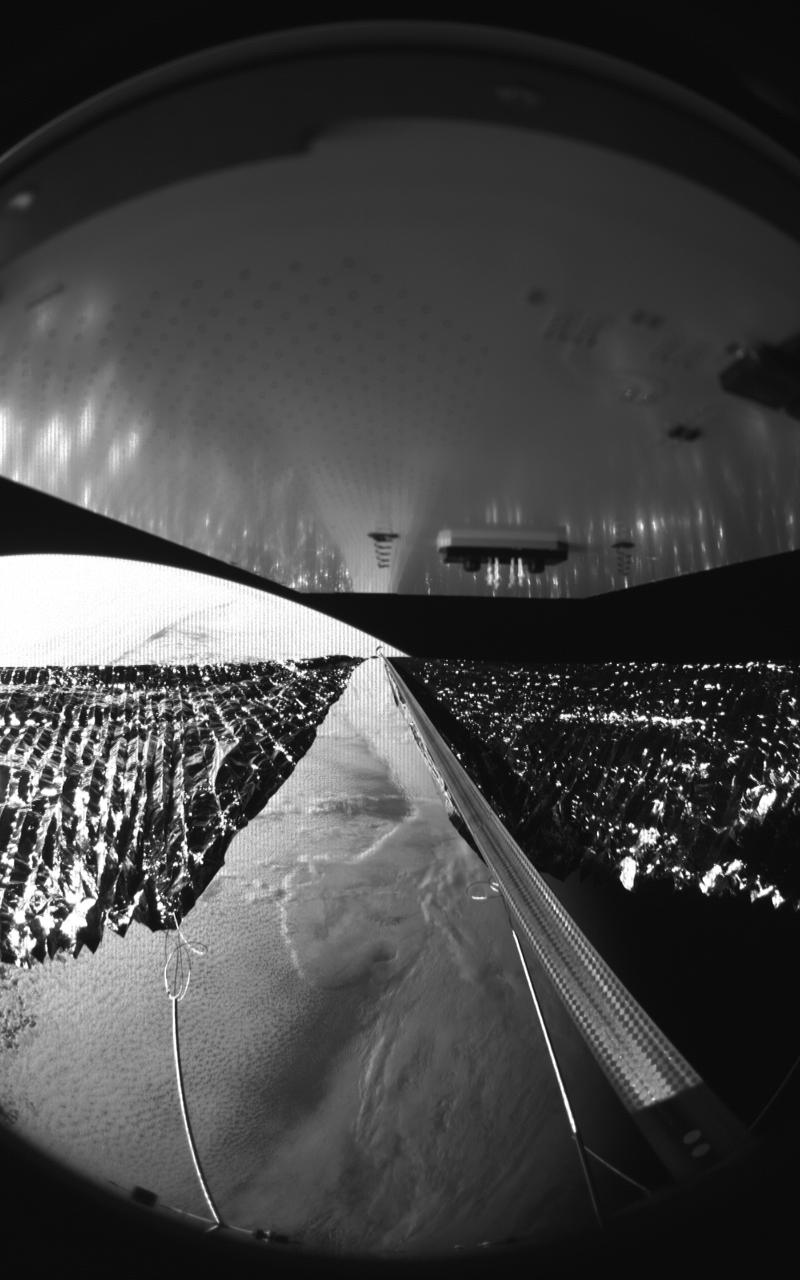
Four cameras aboard the Advanced Composite Solar Sail System spacecraft show the four reflective sail quadrants supported by composite booms. The booms are mounted at right angles and the spacecraft’s solar panel is rectangular, but lines appear distorted because of the wide-angle camera field of view. View from a black-and-white wide-angle camera aboard the Advanced Composite Solar Sail System taken during sail unfurling in low Earth orbit. The spacecraft has four such cameras, centrally located aboard the spacecraft. Here, reflective sail quadrants supported by composite booms are seen when the booms are partially extended and the sail quadrants are not taut. At the top of the photo is the back surface of one of the spacecraft’s solar panels. On the lower left Earth is seen below.
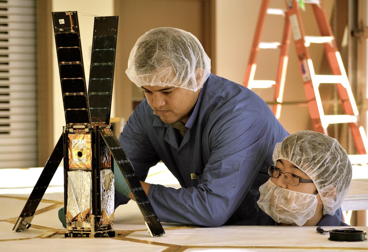
Second Generation Agile Engineering Prototype of Electric Sail 6U CubeSat Testbed Article
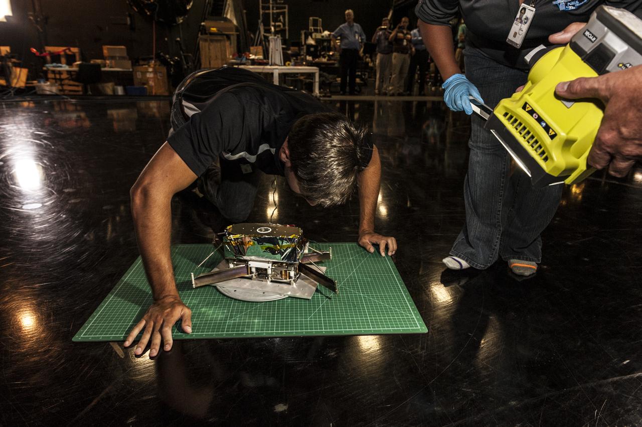
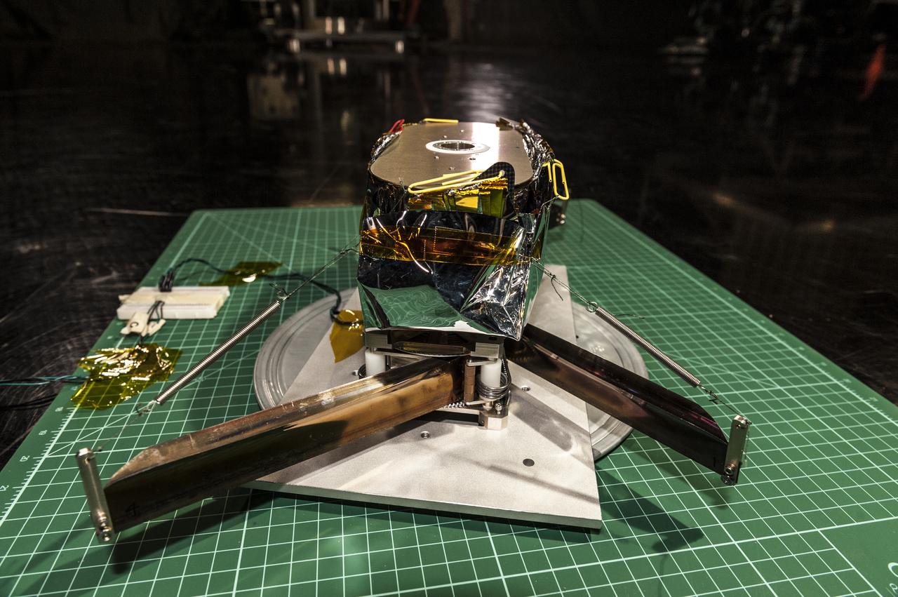
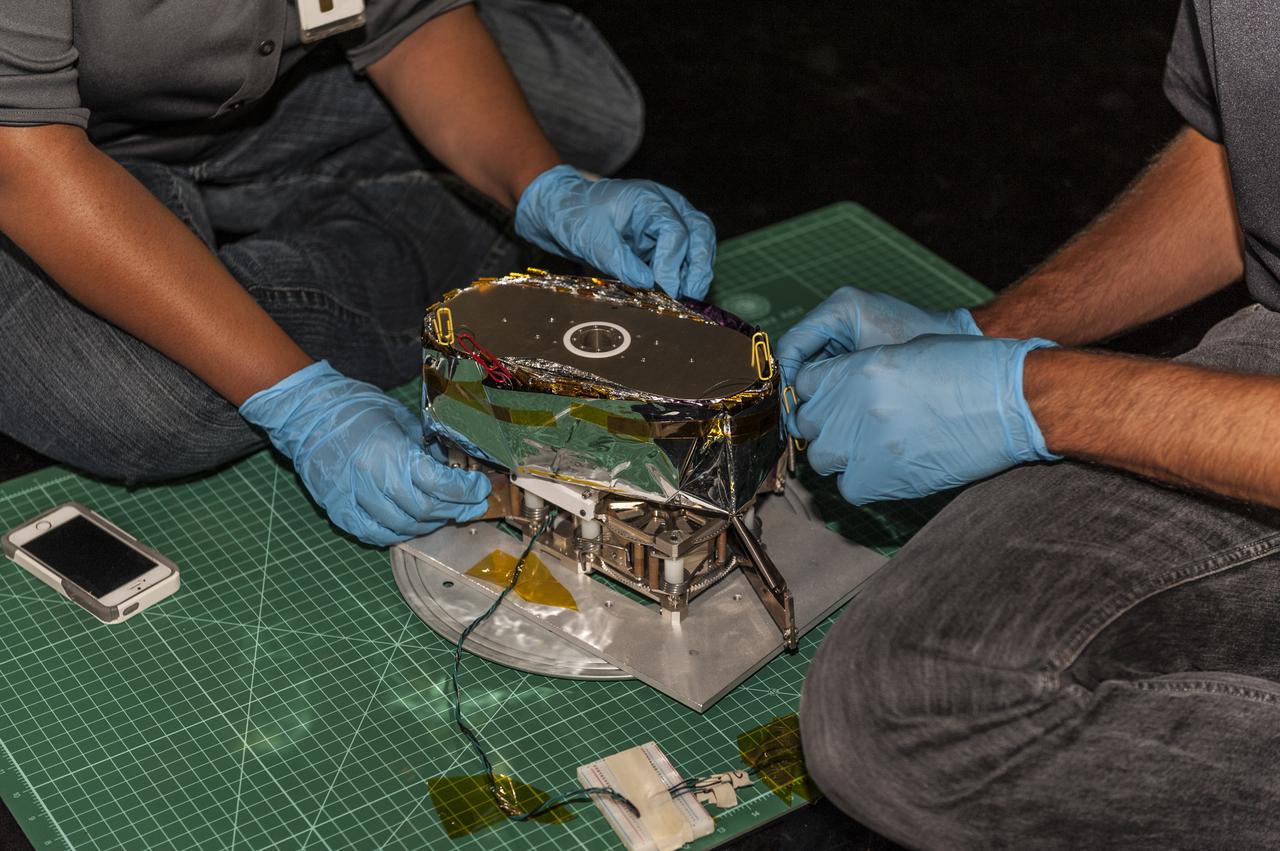
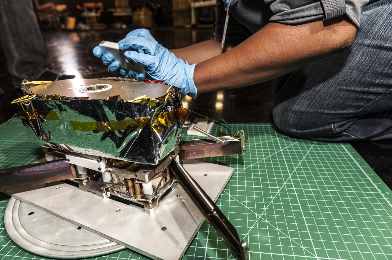
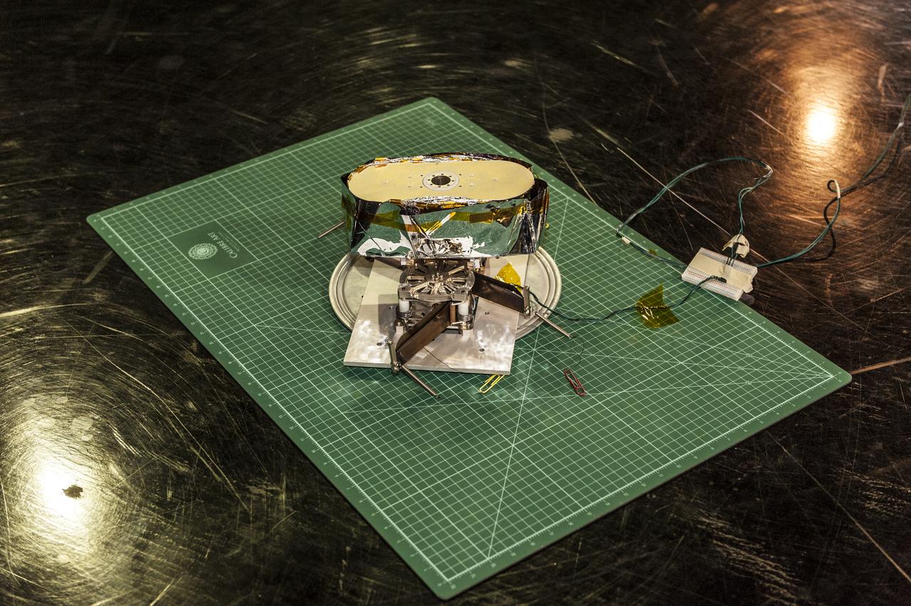
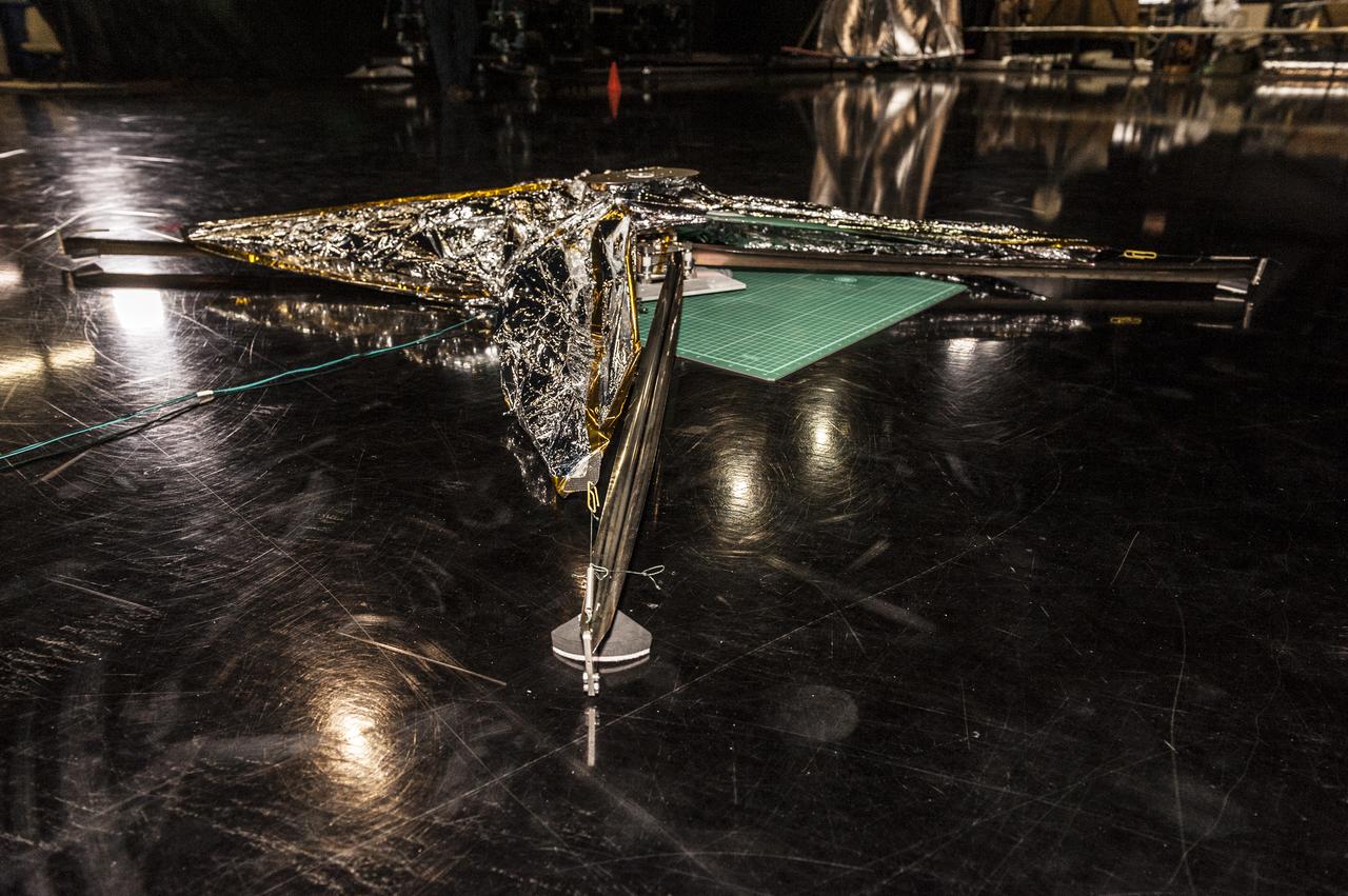
NEA (Near Earth Asteroid) Scout Solar Sail, deployed, with team members: Alex Sobey, Andy Heaton, Olive Stohlmann, Leslie McNutt, Tiffany Russell Lockett, Roy Young, Les Johnson, Kevin Sykes, Tom Bryan
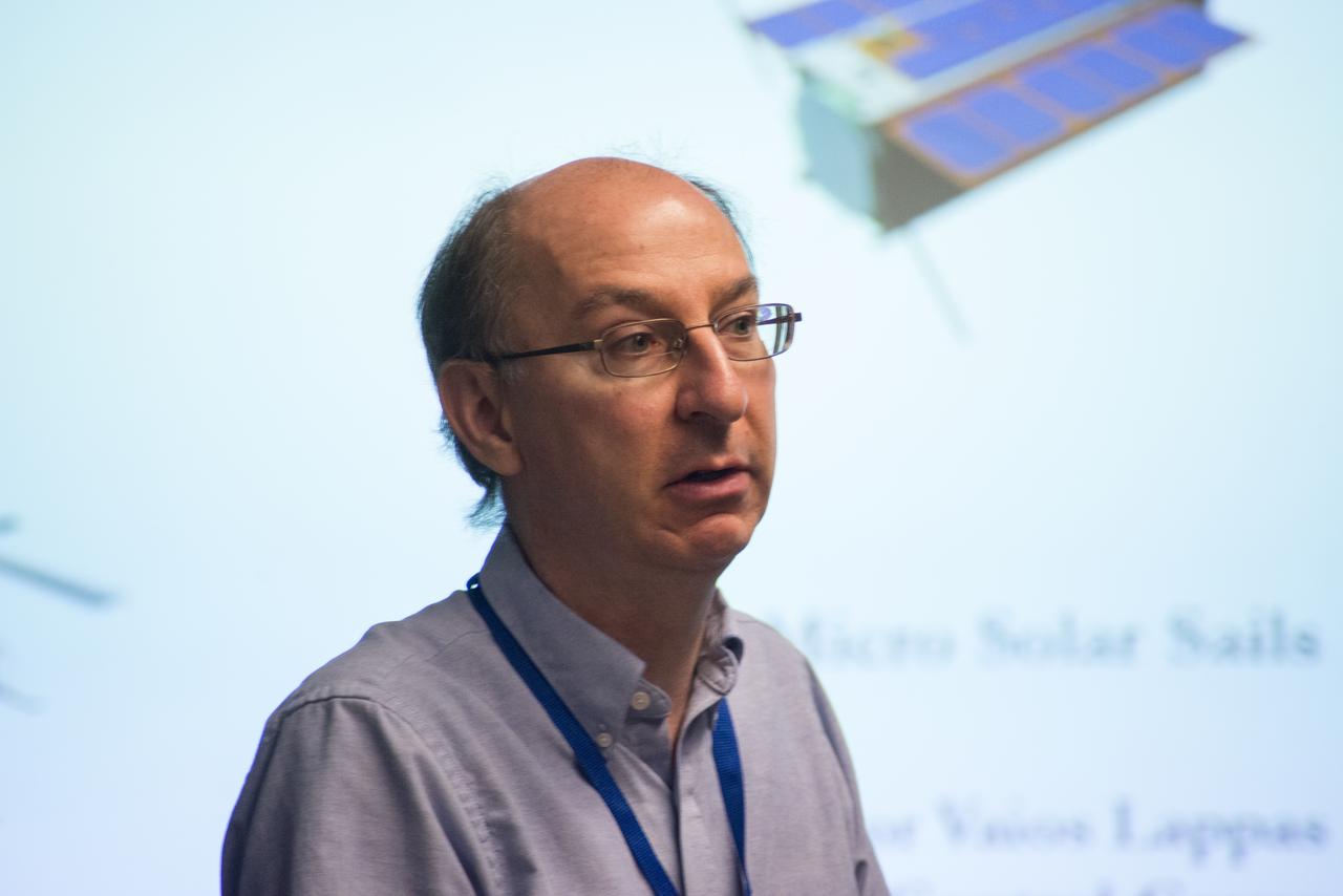
LES JOHNSON INTRODUCES PROFESSOR VARIOS LAPP, UNIVERSITY OF SURREY, UK, PRIME INVESTIGATOR OF SOLAR SAIL TECHNOLOGY
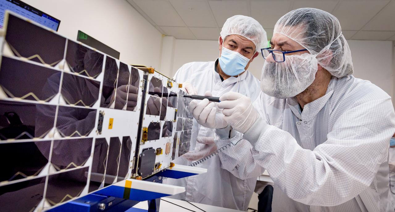
Overview of the solar panels test of the Advanced Composite Solar Sail System (ACS3) spacecraft in the Ames Integration Facility in N213 room 104.
Overview of the -Y axis of the Advanced Composite Solar Sail System (ACS3) spacecraft before the installation of the solar panels in the Ames Integration Facility in N213 room 104.
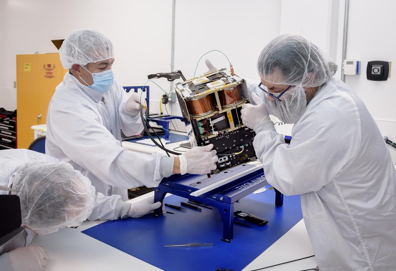
Left to right: Keats Wilkie, Mario Perez, and Craig Turczynski rotate the Advanced Composite Solar Sail System (ACS3) spacecraft on the workbench of the Ames Integration Facility located in N213 room 104.
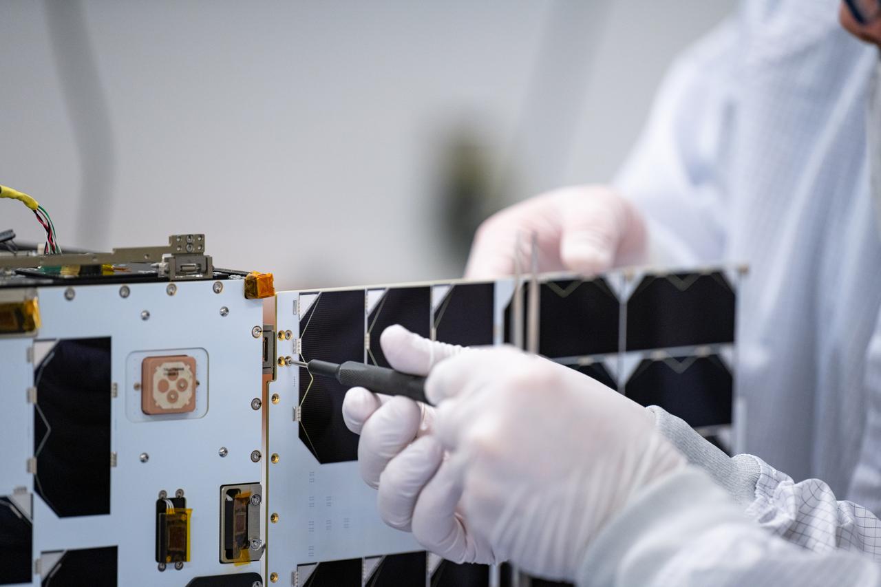
Craig Turczynski, and Mario Perez install the solar panels on the +Y and -Y axis of Advanced Composite Solar Sail System (ACS3) spacecraft in the Ames Integration Facility in N213 room 104.
Mario Perez, back, holds the deployable solar panel as Craig Turczynski, left, secures it to the Advanced Composite Solar Sail System (ACS3) spacecraft in the Ames Integration Facility located in N213 room 104.
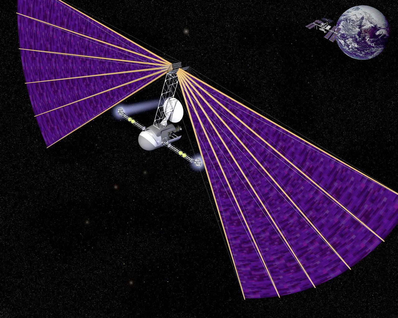
Concept of a vehicle journeys from Earth to Mars propelled by thrusters powered by electricity from photovoltaic cells on its large fan shaped sails
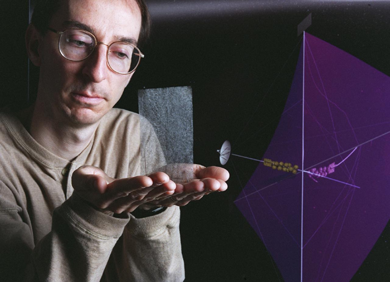
Engineers at Marshall Space Flight Center's (MSFC) Interstellar Propulsion Research department are proposing different solutions to combustion propellants for future space travel. One alternative being tested is the solar sail. The idea is, once deployed, the sail will allow solar winds to propel a spacecraft away from Earth and towards its destination. This would allow a spacecraft to travel indefinitely without the need to refuel during its ong journey. Thin reflective sails could be propelled through space by sunlight, microwave beams, or laser beams, just as the wind pushes sailboats on Earth. The sail will be the largest spacecraft ever built, sparning 440 yards, twice the diameter of the Louisiana Super Dome. Construction materials are being tested in a simulated space environment, where they are exposed to harsh conditions to test their performance and durability in extremely hot and cold temperatures. A leading candidate for the construction material is a carbon fiber material whose density is less than 1/10 ounce per square yard, the equivalent of flattening one raisin to the point that it covers a square yard. In space, the material would unfurl like a fan when it is deployed from an expendable rocket. This photo shows Les Johnson, manager of MSFC's Interstellar Propulsion Research Center holding the rigid, lightweight carbon fiber. An artist's concept of the sail is on the right. Mankind's first venture outside of our solar system is proposed for launch in a 2010 timeframe. An interstellar probe, powered by the fastest spacecraft ever flown, will zoom toward the stars at 58 miles per second. It will cover the distance from New York to Los Angeles in less than a minute and will travel over 23 billion miles beyond the edge of the solar system.
Engineers at Marshall Space Flight Center's Interstellar Propulsion Research department are proposing different solutions to combustion propellants for future space travel. Pictured here is one alternative, the solar sail, depicted through an artist's concept. The idea is, once deployed, the sail will allow solar winds to propel a spacecraft away from Earth and towards its destination. This would allow a spacecraft to travel indefinitely without the need to refuel during its prolong journey. Thin reflective sails could be propelled through space by sunlight, microwave beams, or laser beams, just as the wind pushes sailboats on Earth. The sail will be the largest spacecraft ever built, sparning 440 yards, twice the diameter of the Louisiana Super Dome. Construction materials are being tested in a simulated space environment, where they are exposed to harsh conditions to test their performance and durability in extremely hot and cold temperatures. A leading candidate for the construction material is a carbon fiber material whose density is less than 1/10 ounce per square yard, the equivalent of flattening one raisin to the point that it covers a square yard. In space, the material would unfurl like a fan when it is deployed from an expendable rocket. Mankind's first venture outside of our solar system is proposed for launch in a 2010 timeframe. An interstellar probe, powered by the fastest spacecraft ever flown, will zoom toward the stars at 58 miles per second. It will cover the distance from New York to Los Angeles in less than a minute and will travel over 23 billion miles beyond the edge of the solar system.

SL4-150-5074 (February 1974) --- Scientist-astronaut Edward G. Gibson, science pilot for the Skylab 4 mission, demonstrates the effects of zero-gravity as he sails through airlock module hatch. Photo credit: NASA
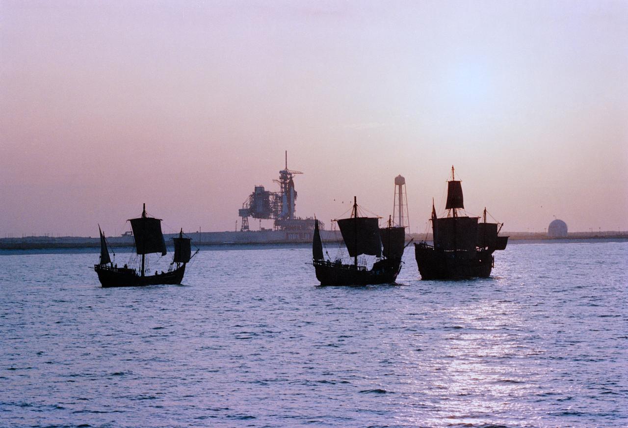
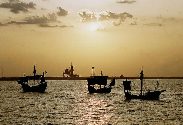
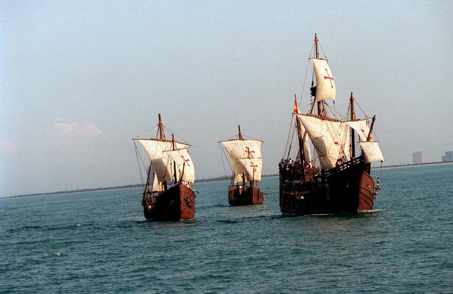
Replicas of Christopher Columbus' sailing ships Santa Maria, Nina, and Pinta sail by Endeavour, Orbiter Vehicle (OV) 105, on Kennedy Space Center (KSC) Launch Complex (LC) Pad 39B awaiting liftoff on its maiden voyage, STS-49. This view was taken from the water showing the three ships silhouetted in the foreground with OV-105 on mobile launcher platform profiled against fixed service structure (FSS) tower and rectracted rotating service structure (RSS) in the background. Next to the launch pad (at right) are the sound suppression water system tower and the liquid hydrogen (LH2) storage tank. View provided by KSC with alternate number KSC-92PC-970.
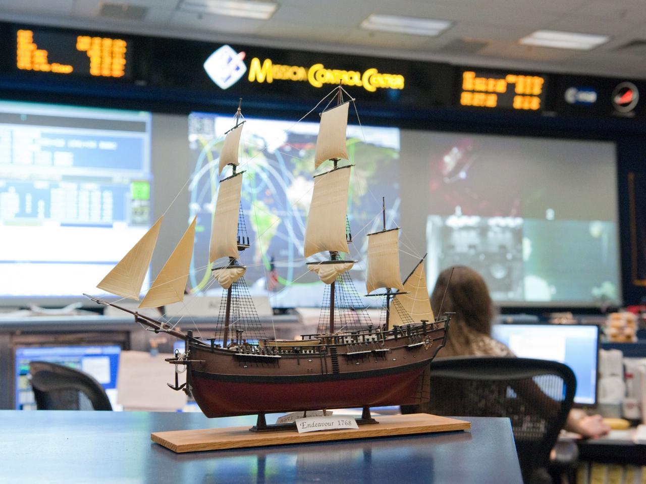
JSC2011-E-046588 (20 May 2011) --- A scale model of HM Bark Endeavour, namesake for the space shuttle currently making its final flight, adorns a console in the space shuttle flight control room in Mission Control in Houston. This model was first displayed in 1992 in the old shuttle control room during STS-49, the inaugural flight of the shuttle Endeavour. It was built by Dan Willett of JSC's Information Resources Directorate. The original sailing ship Endeavour was commanded by Lt. James Cook on a scientific voyage to the South Pacific, Australia and New Zealand from 1768 to 1771. Photo credit: NASA
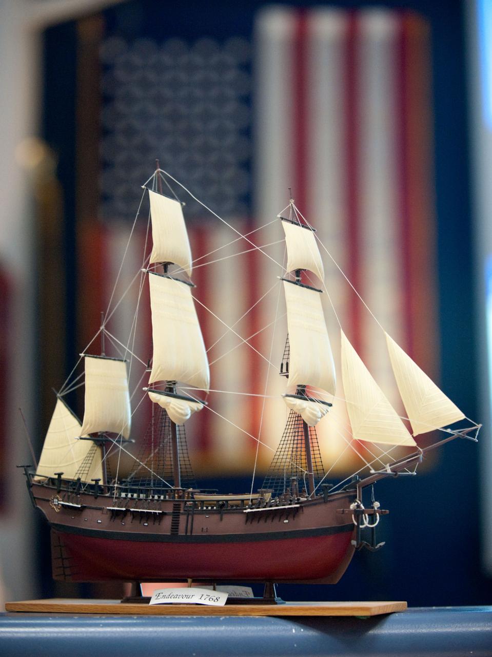
JSC2011-E-046587 (20 May 2011) --- A scale model of HM Bark Endeavour, namesake for the space shuttle currently making its final flight, adorns a console in the space shuttle flight control room in Mission Control in Houston. This model was first displayed in 1992 in the old shuttle control room during STS-49, the inaugural flight of the shuttle Endeavour. It was built by Dan Willett of JSC's Information Resources Directorate. The original sailing ship Endeavour was commanded by Lt. James Cook on a scientific voyage to the South Pacific, Australia and New Zealand from 1768 to 1771. Photo credit: NASA
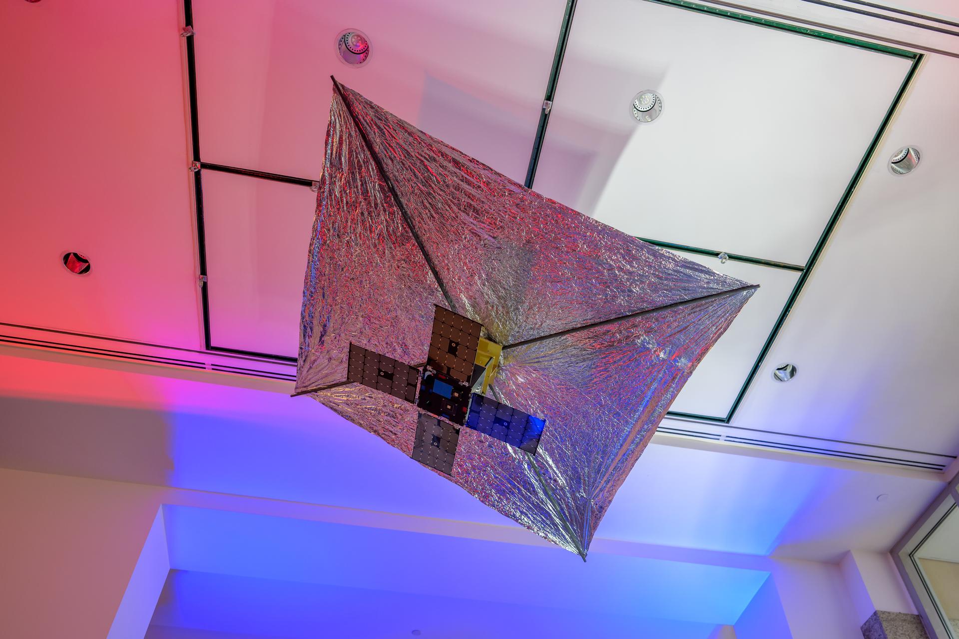
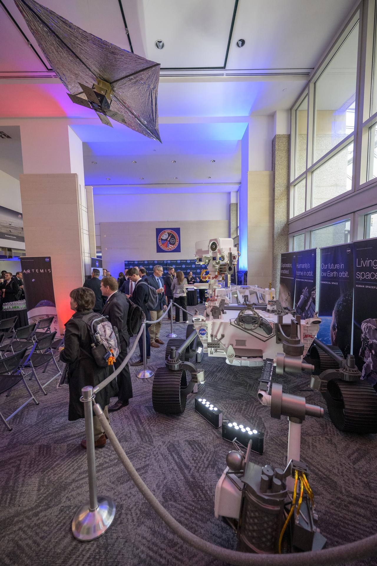
A model of the Advanced Composite Solar Sail System (ACS3) is seen in the NASA Headquarters lobby during a 2-day event where NASA outlined how the agency is executing President Donald J. Trump’s National Space Policy and accelerating preparations for America’s return to the surface of the Moon by 2028, Wednesday, March 25, 2026, at the Mary W. Jackson NASA Headquarters building in Washington. During the event NASA leadership provided updates on mission priorities, including sending the first astronauts to the lunar surface in more than 50 years, establishing the initial elements of a permanent lunar base, getting America underway in space on nuclear propulsion, and other objectives. Photo Credit: (NASA/Bill Ingalls)
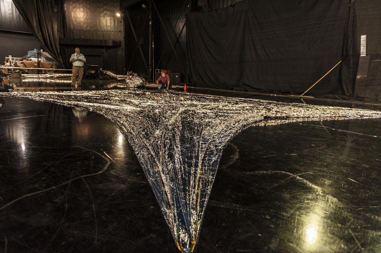
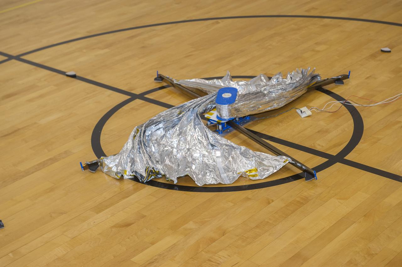
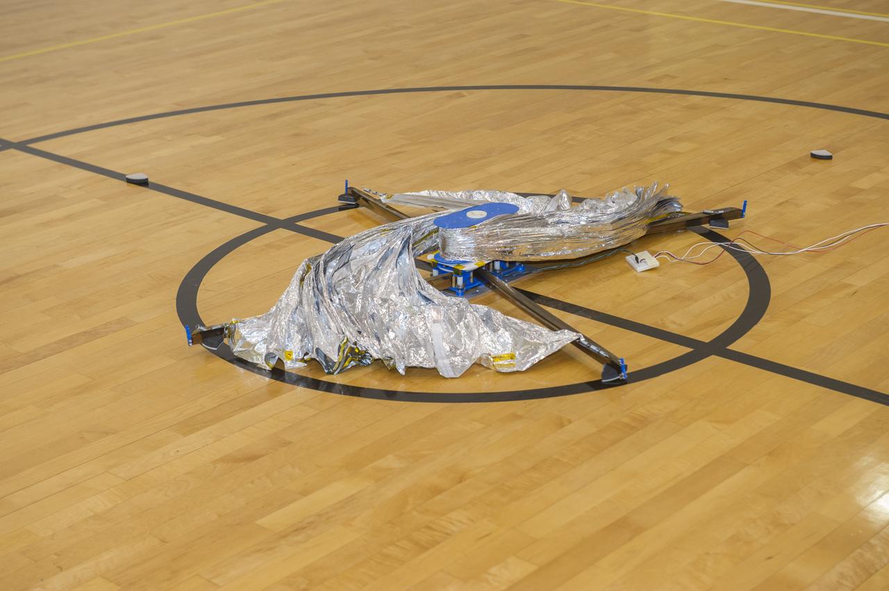
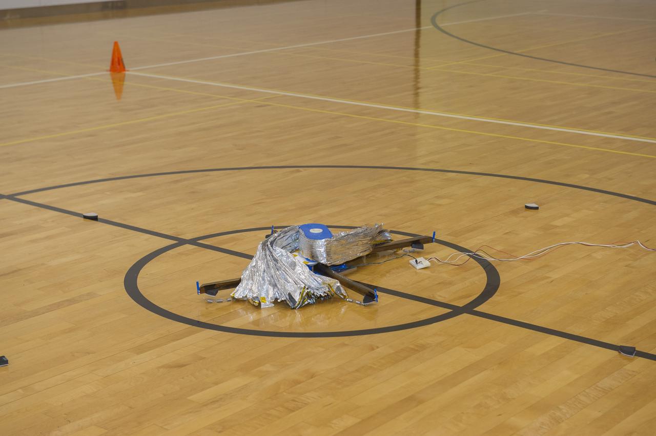
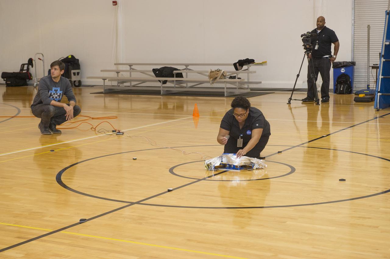
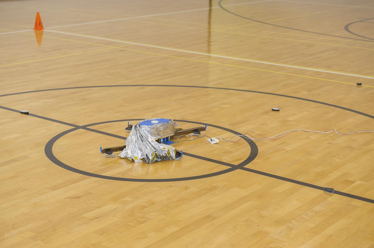
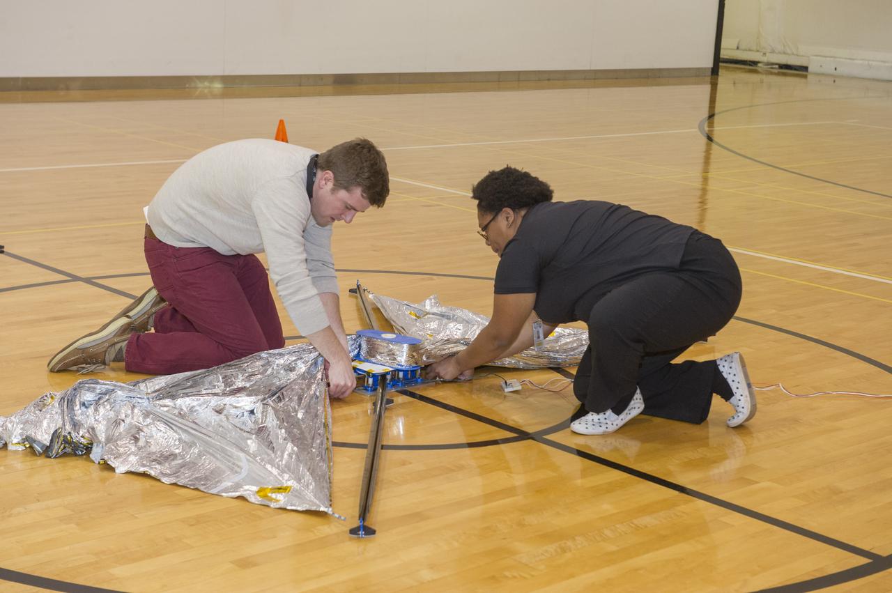
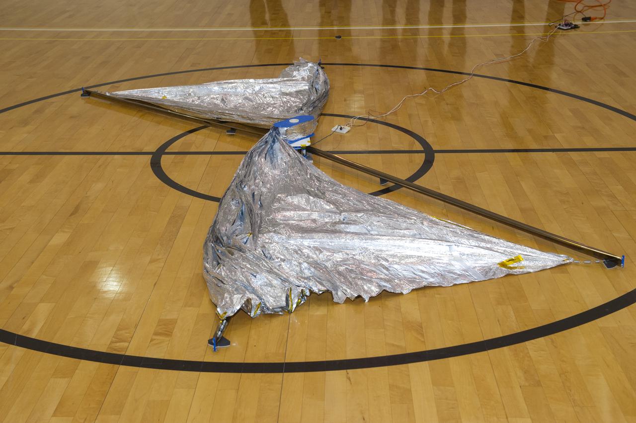
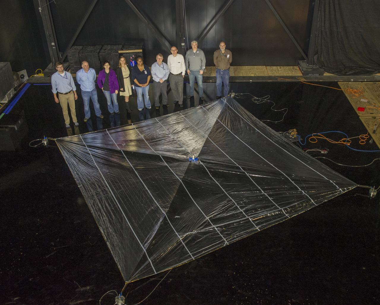
BTK Able 20 meter Solar Sail being deployed with all four sections for the first time. Solar sails are intended for deep space science missions.
BTK Able 20 meter Solar Sail being deployed with all four sections for the first time. Solar sails are intended for deep space science missions.
BTK Able 20 meter Solar Sail being deployed with all four sections for the first time. Solar sails are intended for deep space science missions.
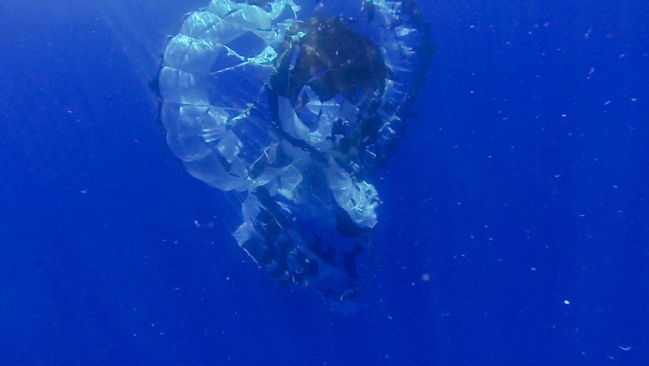
Tears are visible in the parachute from NASA Supersonic Disk Sail Parachute, which did not deploy as expected. The photo was obtained by Navy divers during recovery of the LDSD test vehicle and parachute.
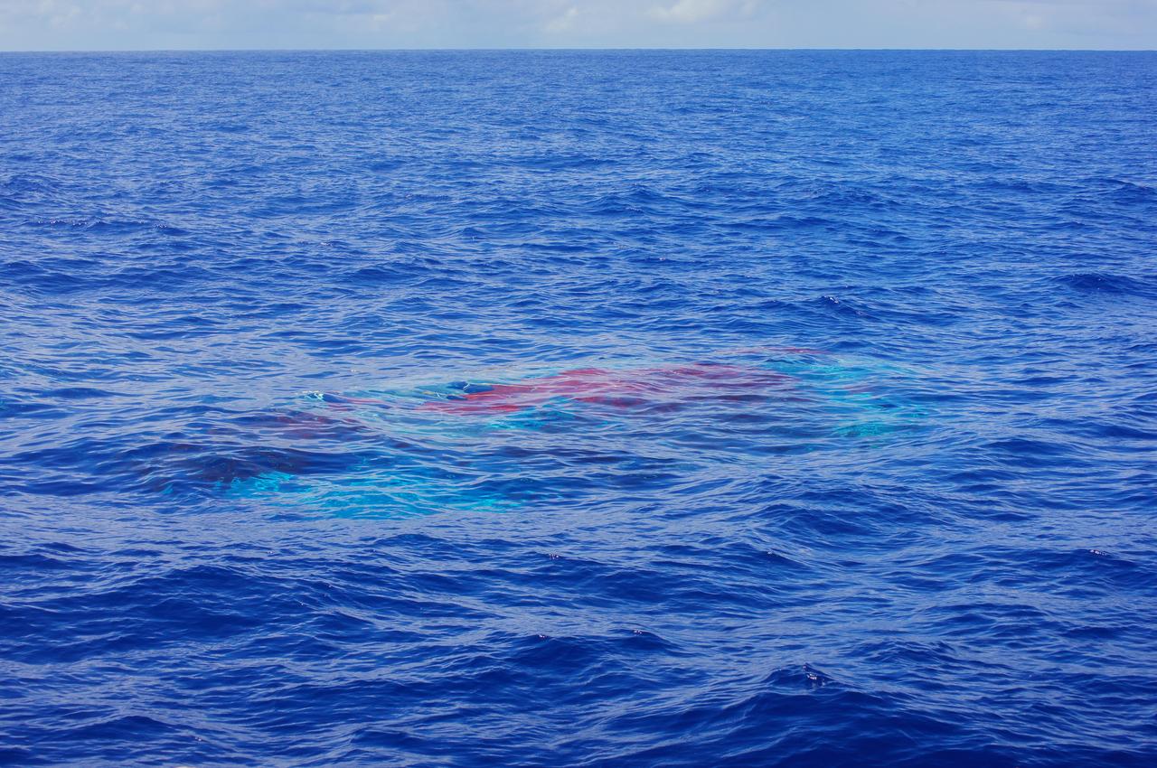
NASA Supersonic Disk Sail Parachute, one of the new technologies being developed as part of NASA Low-Density Supersonic Decelerator LDSD project, floats just below the surface of the Pacific Ocean on June 28, 2014.
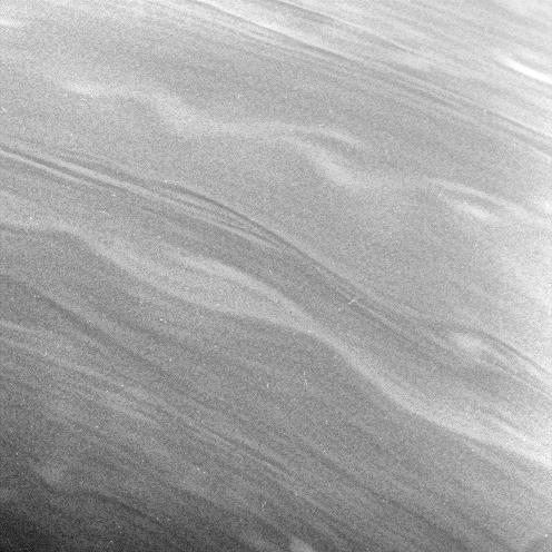
The smooth, linear contours and long, gently meandering character of the clouds in this view suggest stable prevailing winds at these latitudes, from 57 to 67 degrees north on Saturn
CubeSail is a nano-scale flight experiment to demonstrate deployment and control of a single 250-meter (20 m2) solar sail blade as a low-cost risk reduction precursor of the exciting advanced interplanetary UltraSail concept having four 5-kilometer blades (with approximately 100,000 m2 of sail area). CubeSail was built by the University of Illinois at Urbana-Champaign and CU Aerospace, the same team that designed the I-Sail and UltraSail concepts funded by NASA’s SBIR program. CubeSail represents an affordable stepping-stone towards the future development of the UltraSail solar sail concept that would enable very high-energy inner heliosphere and interstellar scientific missions. In addition, near-earth missions such as Heliostorm for early warning of solar storms will provide more warning margin as the solar sail performance is increased with UltraSail technology. Spacecraft design studies show that for sail areal densities below 5 gm/m2, as proposed with UltraSail, that spacecraft payloads can be significantly increased to 50-60% because of the elimination of the propellant, without sacrificing flight time. Furthermore, higher payload fractions will result in dramatically lower total spacecraft mass and consequently much lower launch cost, enabling more missions for the research dollar.
Students Alex Diaz and Riki Munakata of California Polytechnic State University testing the LightSail CubeSat. LightSail is a citizen-funded technology demonstration mission sponsored by the Planetary Society using solar propulsion for CubeSats. The spacecraft is designed to “sail” on the energy of solar photons striking the thin, reflective sail material. The first LightSail mission is designed to test the spacecraft’s critical systems, including the sequence to autonomously deploy a Mylar solar sail with an area of 32 square meters (344 square feet). The Planetary Society is planning a second, full solar sailing demonstration flight for 2016. Light is made of packets of energy called photons. While photons have no mass, they have energy and momentum. Solar sails use this momentum as a method of propulsion, creating flight by light. LightSail’s solar sail is packaged into a three-unit CubeSat about the size of a loaf of bread. Launched by NASA’s CubeSat Launch Initiative on the ELaNa XI mission as an auxiliary payload aboard the U.S. Air Force X-37B space plane mission on May 20, 2015.
CubeSail is a nano-scale flight experiment to demonstrate deployment and control of a single 250-meter (20 m2) solar sail blade as a low-cost risk reduction precursor of the exciting advanced interplanetary UltraSail concept having four 5-kilometer blades (with approximately 100,000 m2 of sail area). CubeSail was built by the University of Illinois at Urbana-Champaign and CU Aerospace, the same team that designed the I-Sail and UltraSail concepts funded by NASA’s SBIR program. CubeSail represents an affordable stepping-stone towards the future development of the UltraSail solar sail concept that would enable very high-energy inner heliosphere and interstellar scientific missions. In addition, near-earth missions such as Heliostorm for early warning of solar storms will provide more warning margin as the solar sail performance is increased with UltraSail technology. Spacecraft design studies show that for sail areal densities below 5 gm/m2, as proposed with UltraSail, that spacecraft payloads can be significantly increased to 50-60% because of the elimination of the propellant, without sacrificing flight time. Furthermore, higher payload fractions will result in dramatically lower total spacecraft mass and consequently much lower launch cost, enabling more missions for the research dollar.
CubeSail is a nano-scale flight experiment to demonstrate deployment and control of a single 250-meter (20 m2) solar sail blade as a low-cost risk reduction precursor of the exciting advanced interplanetary UltraSail concept having four 5-kilometer blades (with approximately 100,000 m2 of sail area). CubeSail was built by the University of Illinois at Urbana-Champaign and CU Aerospace, the same team that designed the I-Sail and UltraSail concepts funded by NASA’s SBIR program. CubeSail represents an affordable stepping-stone towards the future development of the UltraSail solar sail concept that would enable very high-energy inner heliosphere and interstellar scientific missions. In addition, near-earth missions such as Heliostorm for early warning of solar storms will provide more warning margin as the solar sail performance is increased with UltraSail technology. Spacecraft design studies show that for sail areal densities below 5 gm/m2, as proposed with UltraSail, that spacecraft payloads can be significantly increased to 50-60% because of the elimination of the propellant, without sacrificing flight time. Furthermore, higher payload fractions will result in dramatically lower total spacecraft mass and consequently much lower launch cost, enabling more missions for the research dollar.
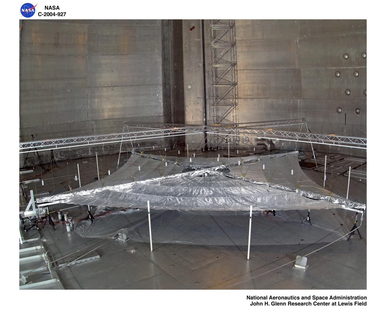
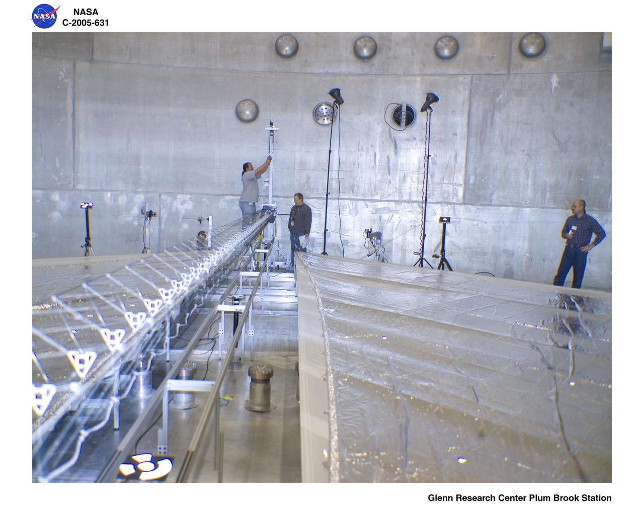
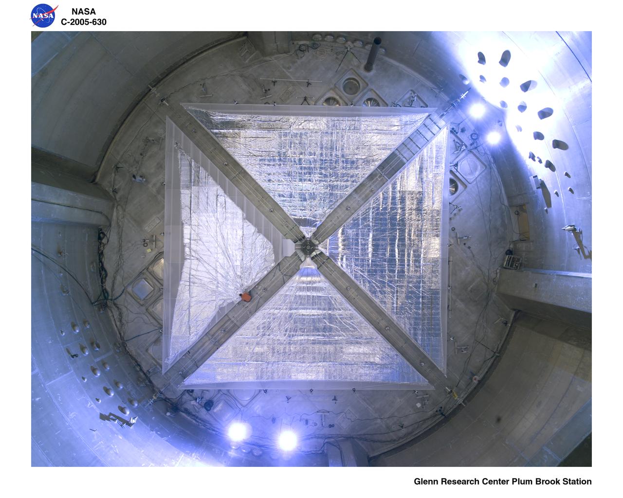
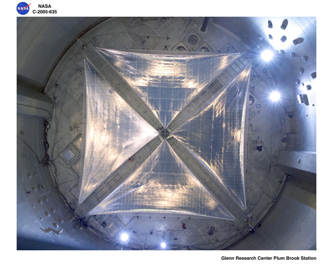
Solar Sail Testing at the Plum Brook Space Power Facility (SPF)
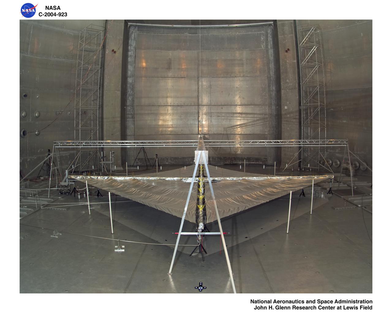
Solar Sail Testing at the Plum Brook Space Power Facility (SPF)
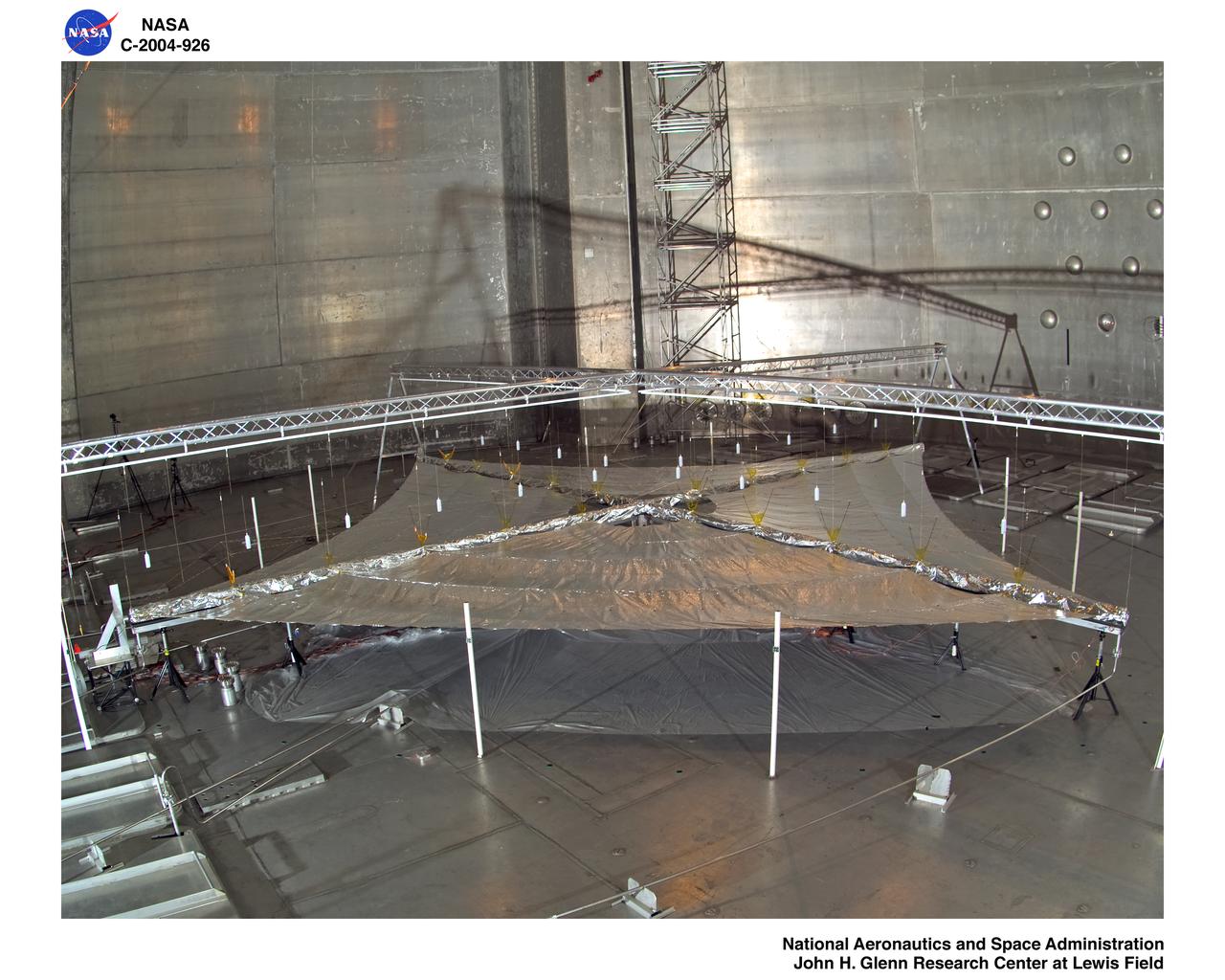
Solar Sail Testing at the Plum Brook Space Power Facility (SPF)
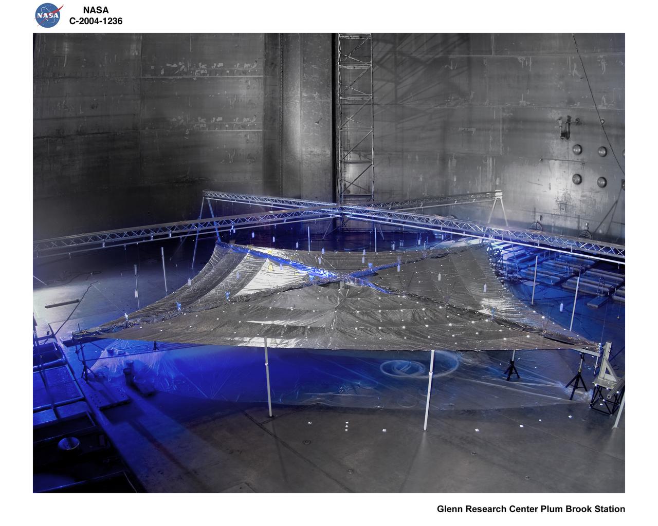
Solar Sail Testing at the NASA Plum Brook Space Power Facility (SPF)
NASA Headquarters lobby is seen with models of the Mars 2020 Perseverance Rover, and Advanced Composite Solar Sail System (ACS3) on display ahead of an event where NASA outlined how the agency is executing President Donald J. Trump’s National Space Policy and accelerating preparations for America’s return to the surface of the Moon by 2028, Tuesday, March 24, 2026, at the Mary W. Jackson NASA Headquarters building in Washington. During the event NASA leadership provided updates on mission priorities, including sending the first astronauts to the lunar surface in more than 50 years, establishing the initial elements of a permanent lunar base, getting America underway in space on nuclear propulsion, and other objectives. Photo Credit: (NASA/Bill Ingalls)
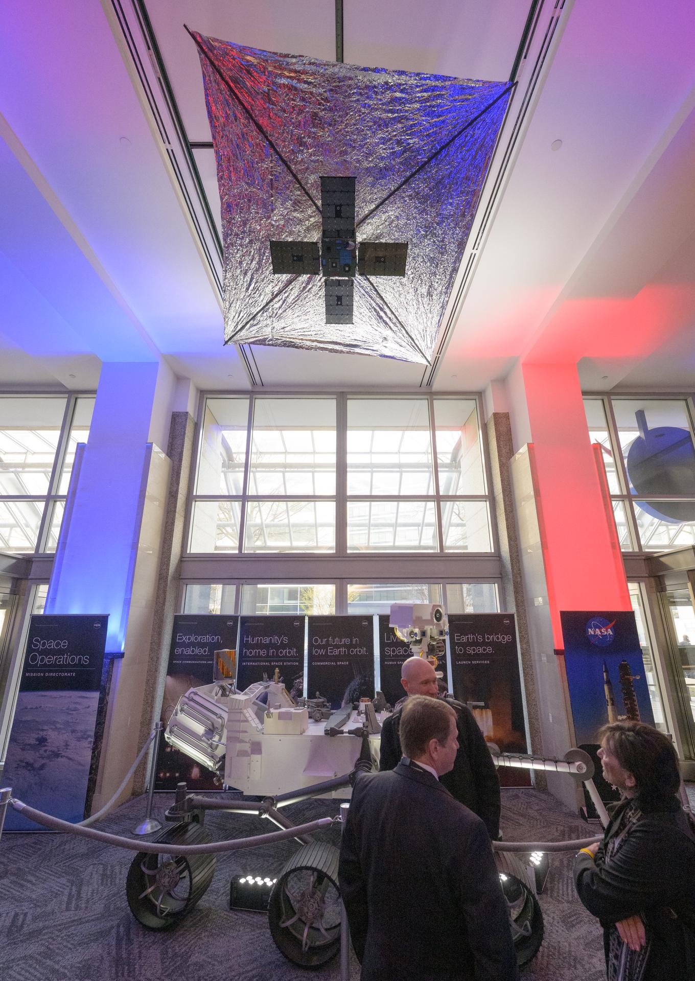
NASA Headquarters lobby is seen with models of the Mars 2020 Perseverance Rover, and Advanced Composite Solar Sail System (ACS3) on display ahead of an event where NASA outlined how the agency is executing President Donald J. Trump’s National Space Policy and accelerating preparations for America’s return to the surface of the Moon by 2028, Tuesday, March 24, 2026, at the Mary W. Jackson NASA Headquarters building in Washington. During the event NASA leadership provided updates on mission priorities, including sending the first astronauts to the lunar surface in more than 50 years, establishing the initial elements of a permanent lunar base, getting America underway in space on nuclear propulsion, and other objectives. Photo Credit: (NASA/Bill Ingalls)
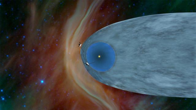
This artist concept shows the general locations of NASA two Voyager spacecraft. Voyager 1 top has sailed beyond our solar bubble into interstellar space. Voyager 2 bottom is still exploring the outer layer of the solar bubble.
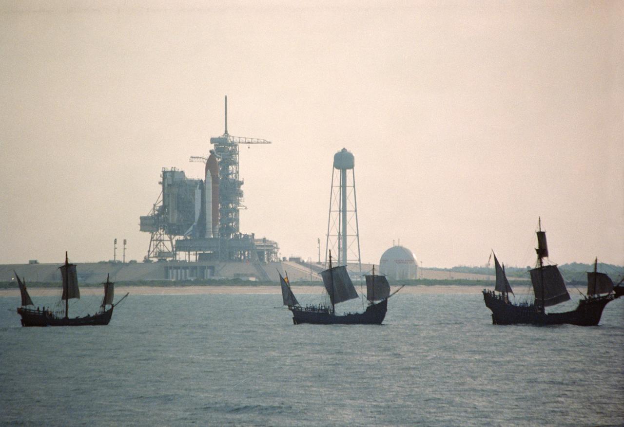
S92-39074 (6 May 1992) --- The centuries-old technology that built Christopher Columbus' three sailing ships passes within a half mile of the 20th-Century Space Shuttle Endeavour, in background, awaiting liftoff on Launch Pad 39B. The replicas of the Santa Maria, Nina, and Pinta wind-powered ships, managed by the Spain '92 Foundation, are on a tour to ports around the Gulf of Mexico and up the Atlantic Coast of the United States. Endeavour is set to lift off on its maiden voyage, STS-49, on May 7, 1992. Video footage of the two types of exploration vessels will be used by NASA for a variety of productions, including the annual Von Braun Exploration forum sponsored by NASA's Marshall Space Flight Center (MSFC), Huntsville, Alabama, in October, 1992. This year's theme is Exploration and the Evolution of Nations. 1992 is the 500th anniversary of Columbus' voyage to the New World.
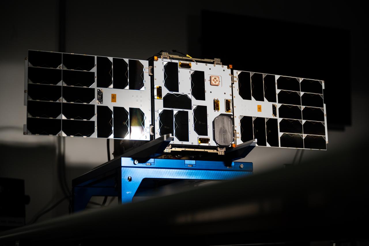
jsc2020e016860 (8/5/2016) --- A view of the fully assembled prototype of Alpha CubeSat. Alpha comprises a 1U CubeSat capable of deploying a free-flying 1m x 1m light sail equipped with 4 chip satellites (ChipSats). The overall goal of the Alpha mission is to serve as a technical demonstration of a light sail in orbit, verifying the properties of a highly retroreflective material for laser propulsion. Image courtesy of Cornell SSDS.
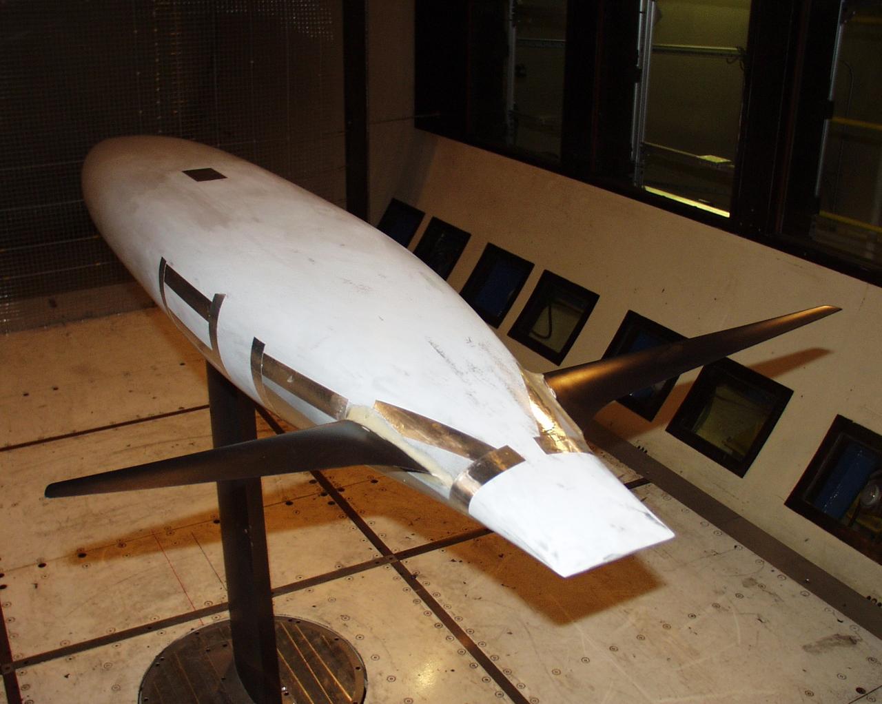
One World Challenge: boat hull configuration optimization test 12-0095 in Ames 12ft pressure wind tunnel. (Three phase Dec 2000 thru May 2002 - America Cup Sailing)
On the 500th arniversary of Christopher Columbus' discovery of the New World, replicas of his three ships sailed past the launch pad at the Kennedy Space Center (KSC) while the space shuttle Columbia sat poised for lift off.
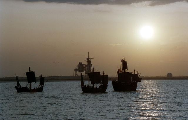
On the 500th arniversary of Christopher Columbus' discovery of the New World, replicas of his three ships sailed past the launch pad at the Kennedy Space Center (KSC) while the space shuttle Columbia sat poised for lift off.
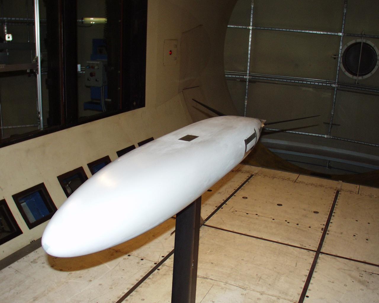

On the 500th arniversary of Christopher Columbus' discovery of the New World, replicas of his three ships sailed past the launch pad at the Kennedy Space Center (KSC) while the space shuttle Columbia sat poised for lift off.

One World Challenge: boat hull configuration optimization test 12-0095 in Ames 12ft pressure wind tunnel. (Three phase Dec 2000 thru May 2002 - America Cup Sailing)
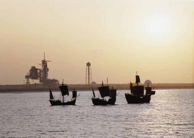
On the 500th arniversary of Christopher Columbus' discovery of the New World, replicas of his three ships sailed past the launch pad at the Kennedy Space Center (KSC) while the space shuttle Columbia sat poised for lift off.
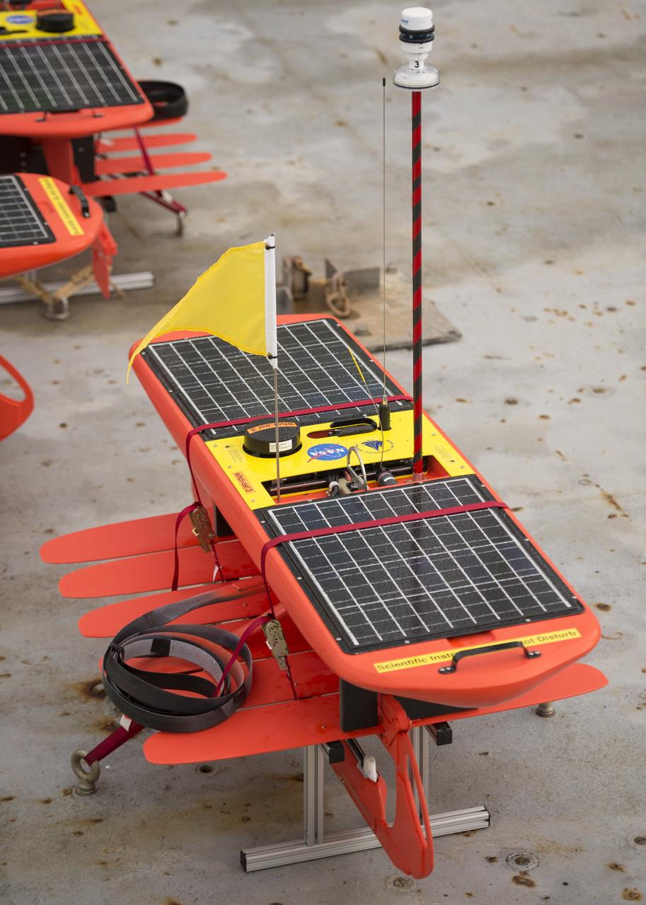
Autonomous wave gliders are seen onboard the the Woods Hole Oceanographic Institution research vessel Knorr on Tuesday, Sept. 4, 2012, in Woods Hole, Mass. The autonomous gliders will be deployed in the Atlantic Ocean as part of the Salinity Processes in the Upper Ocean Regional Study (SPURS) which is set to sail on Sept. 6. The NASA-sponsored expedition will sail to the North Atlantic's saltiest spot to get a detailed, 3-D picture of how salt content fluctuates in the ocean's upper layers and how these variations are related to shifts in rainfall patterns around the planet. Photo Credit: (NASA/Bill Ingalls)
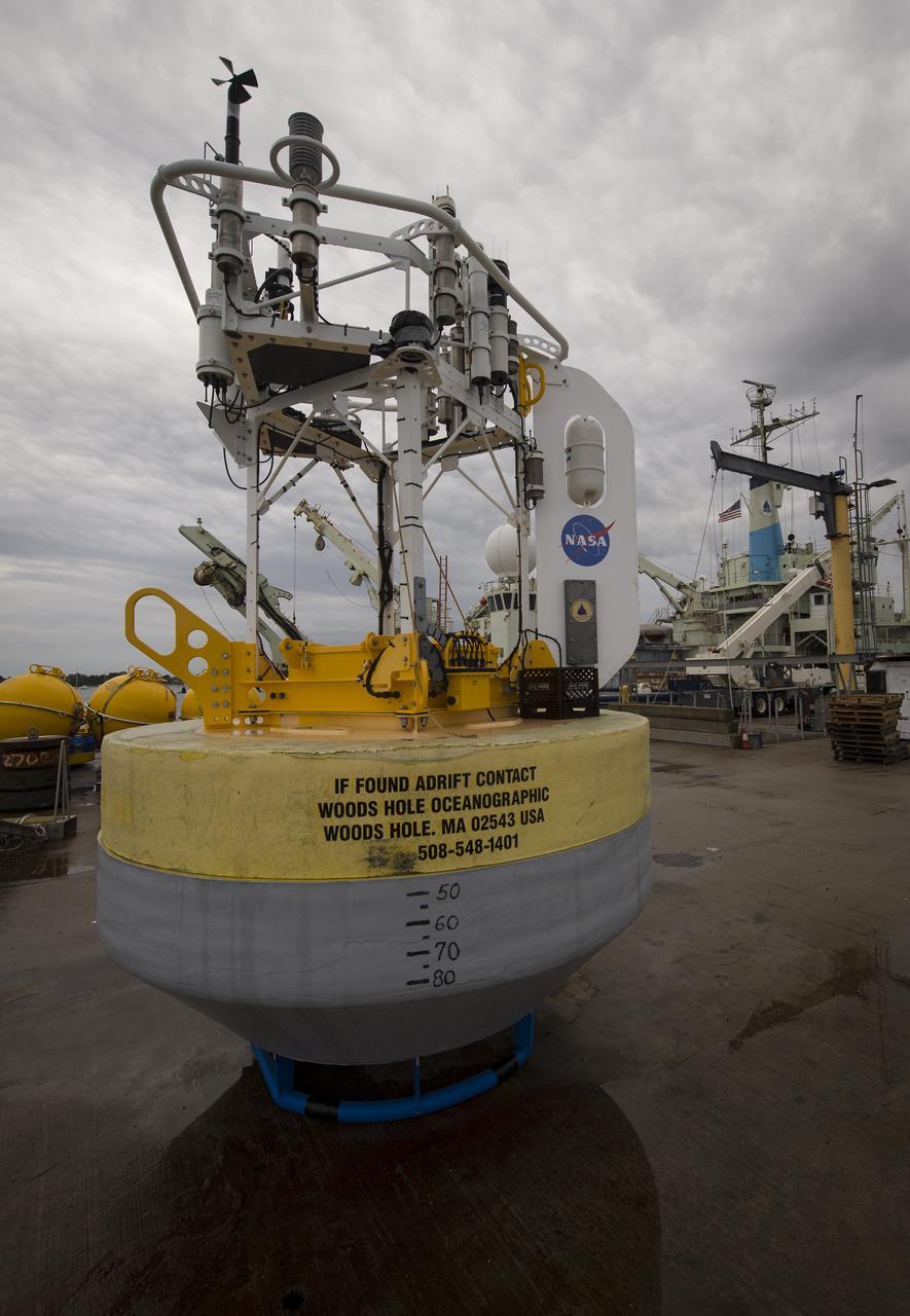
A sensor-laden buoy is seen prior to being loaded onboard the Woods Hole Oceanographic Institution's vessel Knorr on Tuesday, Sept. 4, 2012, in Woods Hole, Mass. The buoy will be deployed in the Atlantic Ocean as part of the Salinity Processes in the Upper Ocean Regional Study (SPURS) which is set to sail on Sept. 6. The NASA-sponsored expedition will sail to the North Atlantic's saltiest spot to get a detailed, 3-D picture of how salt content fluctuates in the ocean's upper layers and how these variations are related to shifts in rainfall patterns around the planet. Photo Credit: (NASA/Bill Ingalls)
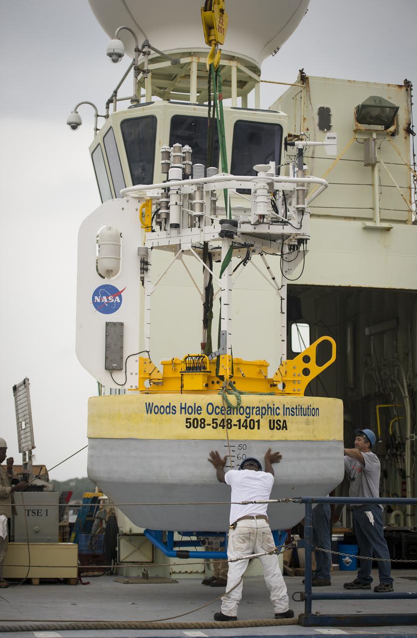
A sensor-laden buoy is lifted onboard the Woods Hole Oceanographic Institution's research vessel Knorr on wednesday, Sept. 5, 2012, in Woods Hole, Mass. The buoy will be deployed in the Atlantic Ocean as part of the Salinity Processes in the Upper Ocean Regional Study (SPURS) which is set to sail on Sept. 6. The NASA-sponsored expedition will sail to the North Atlantic's saltiest spot to get a detailed, 3-D picture of how salt content fluctuates in the ocean's upper layers and how these variations are related to shifts in rainfall patterns around the planet. Photo Credit: (NASA/Bill Ingalls)
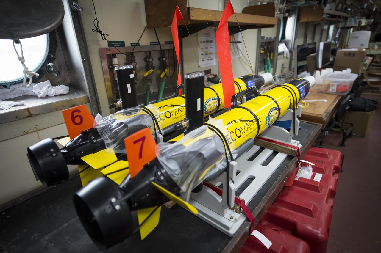
Two EcoMapper AUVs (autonomous underwater vehicles) are seen onboard the the Woods Hole Oceanographic Institution research vessel Knorr on Tuesday, Sept. 4, 2012, in Woods Hole, Mass. The EcoMappers will be deployed in the Atlantic Ocean as part of the Salinity Processes in the Upper Ocean Regional Study (SPURS) which is set to sail on Sept. 6. The NASA-sponsored expedition will sail to the North Atlantic's saltiest spot to get a detailed, 3-D picture of how salt content fluctuates in the ocean's upper layers and how these variations are related to shifts in rainfall patterns around the planet. Photo Credit: (NASA/Bill Ingalls)
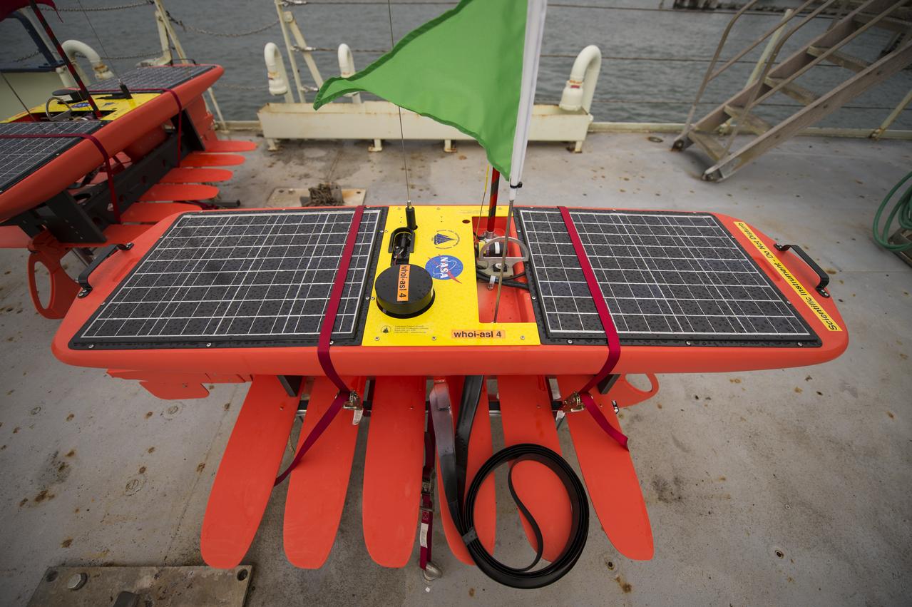
Autonomous wave gliders are seen onboard the the Woods Hole Oceanographic Institution research vessel Knorr on Tuesday, Sept. 4, 2012, in Woods Hole, Mass. The autonomous gliders will be deployed in the Atlantic Ocean as part of the Salinity Processes in the Upper Ocean Regional Study (SPURS) which is set to sail on Sept. 6. The NASA-sponsored expedition will sail to the North Atlantic's saltiest spot to get a detailed, 3-D picture of how salt content fluctuates in the ocean's upper layers and how these variations are related to shifts in rainfall patterns around the planet. Photo Credit: (NASA/Bill Ingalls)