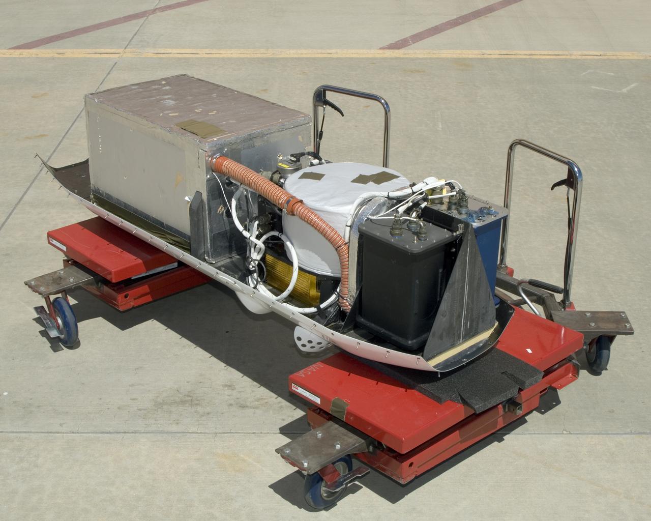
The instruments that make up the Ames Autonomous Module Scanner (AMS) that provided precise thermal-infrared imaging during the Western States Fire Mission in 2007 are detailed in this photo of the AMS as mounted on Ikhana's pod tray. The large foil-covered foam-insulated box at left covers the pressure vessel containing the data system computers and other electronics. The round white-topped assembly is the scan head, including the scan mirror, folded telescope, blackbody references, spectrometer and detectors. Two pressure boxes visible at the forward end of the tray contain the Applanix POS/AV precision navigation subsystem (black) and the power distributor including circuit breakers and ancillary wiring, scan motor controller and the blackbody reference temperature controller (blue).
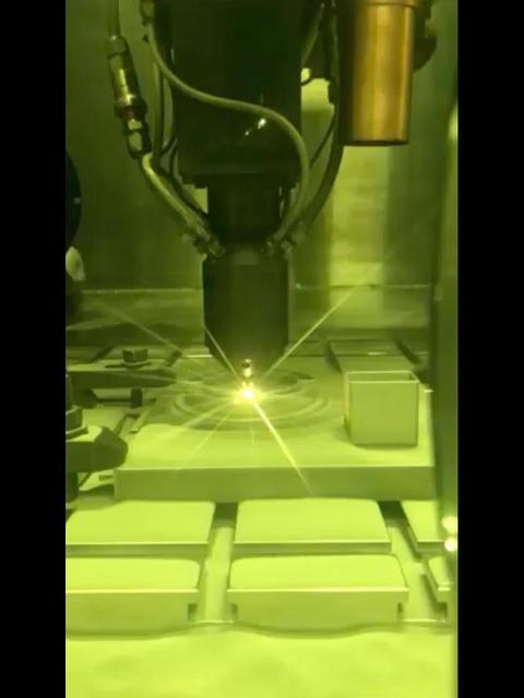
This video clip shows a 3D printing technique where a printer head scans over each layer of a part, blowing metal powder that is melted by a laser. It's one of several ways parts are 3D printed at NASA's Jet Propulsion Laboratory, but was not used to create the parts aboard the Perseverance rover. Movie available at https://photojournal.jpl.nasa.gov/catalog/PIA23972

KENNEDY SPACE CENTER, FLA. - Members of the ice team review final details before heading to Launch Pad 39B and their part in the launch of Space Shuttle Discovery on Return to Flight mission STS-114. After the fuel tanking, they will be scanning and inspecting the fuel tank and other hardware on the Space Shuttle for any evidence of ice or debris. Discovery is scheduled to launch on the historic Return to Flight mission STS-114 at 3:51 p.m. July 13 with a crew of seven.

KENNEDY SPACE CENTER, FLA. - Members of the ice team review final details before heading to Launch Pad 39B and their part in the launch of Space Shuttle Discovery on Return to Flight mission STS-114. After the fuel tanking, they will be scanning and inspecting the fuel tank and other hardware on the Space Shuttle for any evidence of ice or debris. Discovery is scheduled to launch on the historic Return to Flight mission STS-114 at 3:51 p.m. July 13 with a crew of seven.
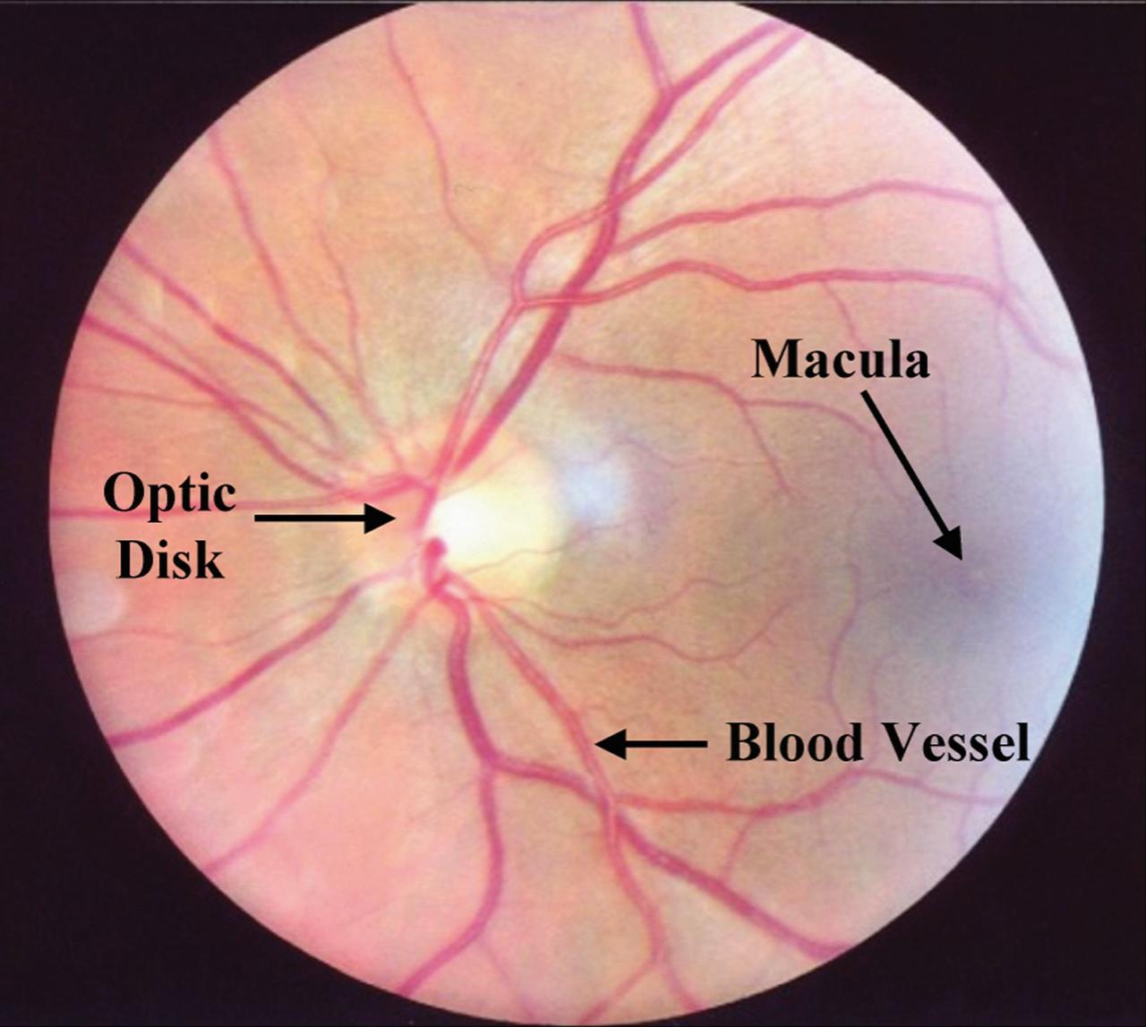
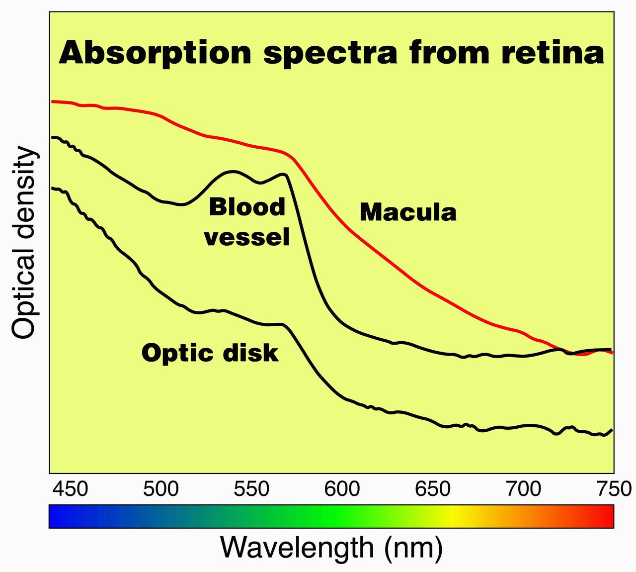
ProVision Technologies, a NASA commercial space center at Sternis Space Center in Mississippi, has developed a new hyperspectral imaging (HSI) system that is much smaller than the original large units used aboard remote sensing aircraft and satellites. The new apparatus is about the size of a breadbox. HSI may be useful to ophthalmologists to study and diagnose eye health, both on Earth and in space, by examining the back of the eye to determine oxygen and blood flow quickly and without any invasion. ProVision's hyperspectral imaging system can scan the human eye and produce a graph showing optical density or light absorption, which can then be compared to a graph from a normal eye. Scans of the macula, optic disk or optic nerve head, and blood vessels can be used to detect anomalies and identify diseases in this delicate and important organ. ProVision has already developed a relationship with the University of Alabama at Birmingham, but is still on the lookout for a commercial partner in this application.
ProVision Technologies, a NASA research partnership center at Sternis Space Center in Mississippi, has developed a new hyperspectral imaging (HSI) system that is much smaller than the original large units used aboard remote sensing aircraft and satellites. The new apparatus is about the size of a breadbox. HSI may be useful to ophthalmologists to study and diagnose eye health, both on Earth and in space, by examining the back of the eye to determine oxygen and blood flow quickly and without any invasion. ProVision's hyperspectral imaging system can scan the human eye and produce a graph showing optical density or light absorption, which can then be compared to a graph from a normal eye. Scans of the macula, optic disk or optic nerve head, and blood vessels can be used to detect anomalies and identify diseases in this delicate and important organ. ProVision has already developed a relationship with the University of Alabama at Birmingham, but is still on the lookout for a commercial partner in this application.
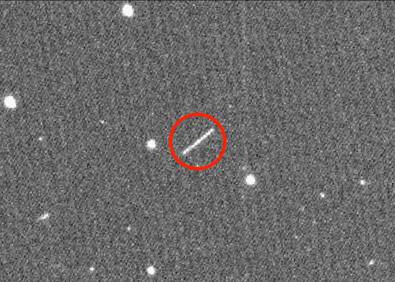
The streak circled in the center of this image is asteroid 2020 QG, which came closer to Earth than any other nonimpacting asteroid on record. It was detected by the Zwicky Transient Facility on Sunday, Aug. 16 at 12:08 a.m. EDT (Saturday, Aug. 15 at 9:08 p.m. PDT). The wide-field camera image of the Zwicky Transient Facility, a sky-scanning survey telescope funded by the National Science Foundation and NASA, and based at Caltech's Palomar Observatory in Southern California. The image was taken six hours after the close approach, as the asteroid was heading away from Earth. https://photojournal.jpl.nasa.gov/catalog/PIA24038
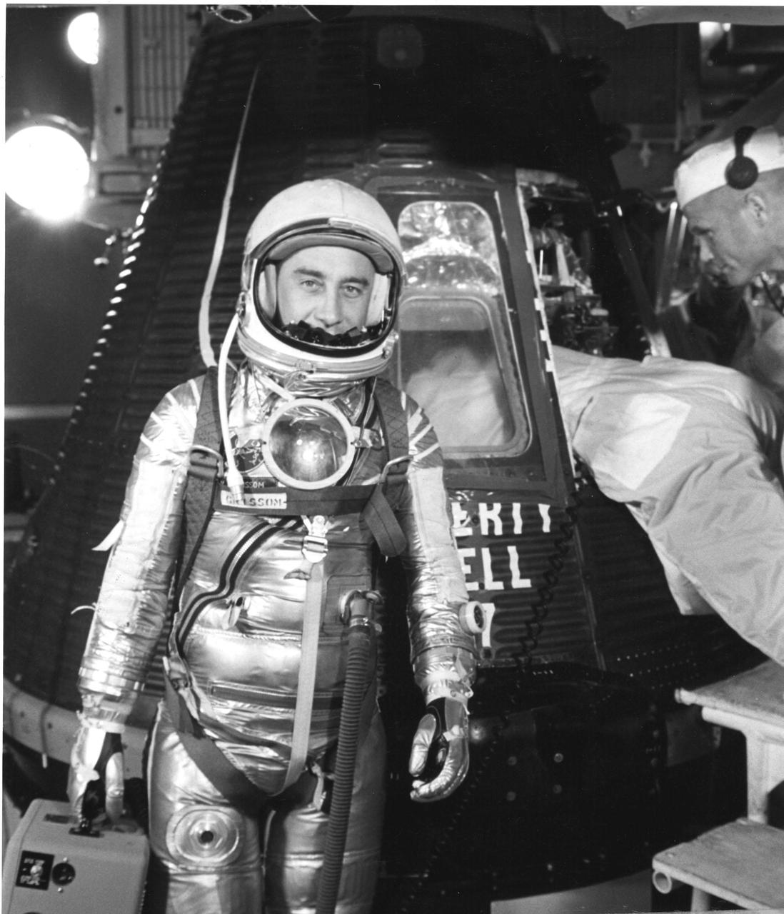
KENNEDY SPACE CENTER, FLA. -- READY FOR FLIGHT - On level three of gantry on pad 5, Project Mercury astronaut Virgil I. 'Gus' Grissom pauses briefly while a technician completes final adjustment in the Liberty Bell 7 spacecraft, which carried Grissom 118 miles into space on Friday, July 21, 1961. The craft's large trapezoidal observation window can be seen behind the pilot. The Pilot Observer Camera, which brought the astronaut's head and shoulders into view, was to reflect the lights on the flight events sequence panel through the 5-inch plexiglas parabolic mirror attached to Grissom's suit, to provide and accurately time record the pilot's voice communications, eye scan pattern and arm motions. The spacecraft sank on landing and has not been recovered. (NASA Photo)
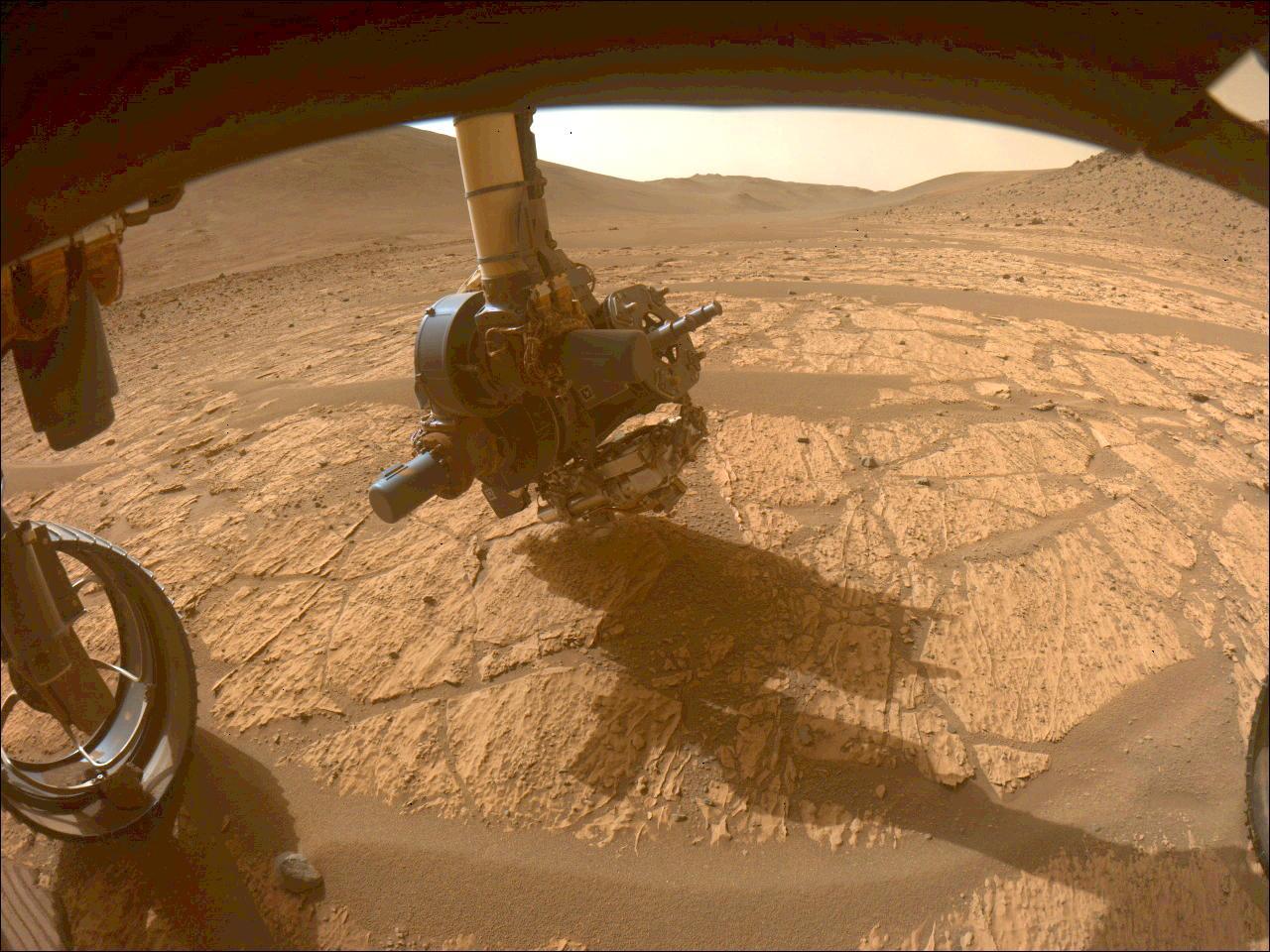
This image shows the WATSON camera aboard NASA's Perseverance Mars rover gathering data on the "Walhalla Glades" abrasion patch. It was taken in the "Bright Angel" region of Jezero Crater by one of the rover's front hazard avoidance cameras on June 14, 2024, the 1,180th Martian day, or sol, of the mission. WATSON (Wide Angle Topographic Sensor for Operations and eNgineering) is located on the SHERLOC (Scanning Habitable Environments with Raman and Luminescence for Organics and Chemicals) instrument at the end of Perseverance's long robotic arm. In this image, SHERLOC is at the bottom of the turret. The WATSON camera head is closest to the surface, and SHERLOC's Autofocus and Context Imager (another camera) is to the right, closer to the drill. A key objective for Perseverance's mission on Mars is astrobiology, including the search for signs of ancient microbial life. The rover is also characterizing the planet's geology and past climate, which paves the way for human exploration of the Red Planet. JPL, which is managed for NASA by Caltech in Pasadena, California, built and manages operations of the Perseverance rover. https://photojournal.jpl.nasa.gov/catalog/PIA26320
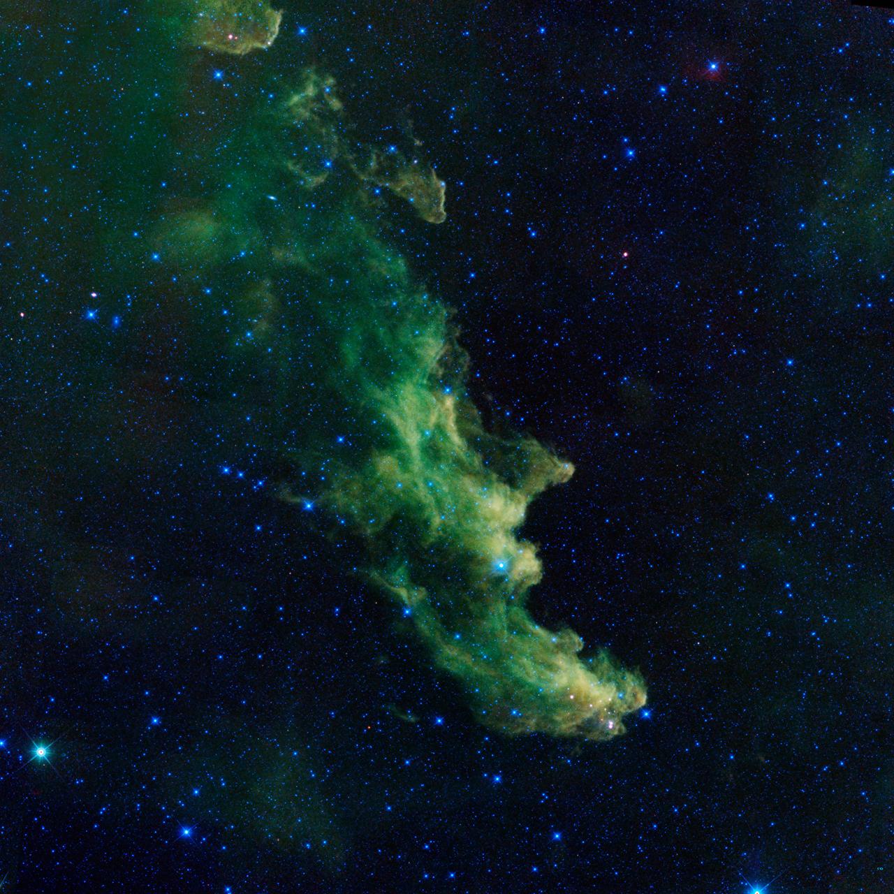
A witch appears to be screaming out into space in this new image from NASA's Wide-Field Infrared Survey Explorer, or WISE. The infrared portrait shows the Witch Head nebula, named after its resemblance to the profile of a wicked witch. Astronomers say the billowy clouds of the nebula, where baby stars are brewing, are being lit up by massive stars. Dust in the cloud is being hit with starlight, causing it to glow with infrared light, which was picked up by WISE's detectors. The Witch Head nebula is estimated to be hundreds of light-years away in the Orion constellation, just off the famous hunter's knee. WISE was recently "awakened" to hunt for asteroids in a program called NEOWISE. The reactivation came after the spacecraft was put into hibernation in 2011, when it completed two full scans of the sky, as planned. Image credit: NASA/JPL-Caltech <b><a href="http://www.nasa.gov/audience/formedia/features/MP_Photo_Guidelines.html" rel="nofollow">NASA image use policy.</a></b> <b><a href="http://www.nasa.gov/centers/goddard/home/index.html" rel="nofollow">NASA Goddard Space Flight Center</a></b> enables NASA’s mission through four scientific endeavors: Earth Science, Heliophysics, Solar System Exploration, and Astrophysics. Goddard plays a leading role in NASA’s accomplishments by contributing compelling scientific knowledge to advance the Agency’s mission. <b>Follow us on <a href="http://twitter.com/NASA_GoddardPix" rel="nofollow">Twitter</a></b> <b>Like us on <a href="http://www.facebook.com/pages/Greenbelt-MD/NASA-Goddard/395013845897?ref=tsd" rel="nofollow">Facebook</a></b> <b>Find us on <a href="http://instagram.com/nasagoddard?vm=grid" rel="nofollow">Instagram</a></b>

A witch appears to be screaming out into space in this new image from NASA's Wide-Field Infrared Survey Explorer, or WISE. The infrared portrait shows the Witch Head nebula, named after its resemblance to the profile of a wicked witch. Astronomers say the billowy clouds of the nebula, where baby stars are brewing, are being lit up by massive stars. Dust in the cloud is being hit with starlight, causing it to glow with infrared light, which was picked up by WISE's detectors. The Witch Head nebula is estimated to be hundreds of light-years away in the Orion constellation, just off the famous hunter's knee. WISE was recently "awakened" to hunt for asteroids in a program called NEOWISE. The reactivation came after the spacecraft was put into hibernation in 2011, when it completed two full scans of the sky, as planned. Image credit: NASA/JPL-Caltech NASA image use policy. ( http://www.nasa.gov/audience/formedia/features/MP_Photo_Guidelines.html ) NASA Goddard Space Flight Center ( http://www.nasa.gov/centers/goddard/home/index.html ) enables NASA’s mission through four scientific endeavors: Earth Science, Heliophysics, Solar System Exploration, and Astrophysics. Goddard plays a leading role in NASA’s accomplishments by contributing compelling scientific knowledge to advance the Agency’s mission. Follow us on Twitter ( http://twitter.com/NASA_GoddardPix ) Like us on Facebook ( http://www.facebook.com/pages/Greenbelt-MD/NASA-Goddard/395013845897?ref=tsd ) Find us on Instagram ( http://instagram.com/nasagoddard?vm=grid )

Stitched together from 79 individual images, this Mastcam-Z right-eye 110-mm zoom mosaic is from the camera's first high-resolution panorama imaging sequence. These images were taken on the afternoon of Sol 4 (Feb. 22, 2021) of the mission; a sol is a Martian day. The camera was commanded to take these images by scanning the mast, or "head," a full 360-degrees around the horizon visible from the landing site. The top of some of the distant crater rim is cut off in some images to ensure the images would cover the front ridge of the Jezero Crater's ancient delta, which is only about 1.25 miles (2 kilometers) away from the rover in the center of this panorama. At that distance and focal length, Mastcam-Z can resolve features as small as about 50 centimeters (1.6 feet) across along the front of the delta. The mosaic is not white balanced but is instead displayed in a preliminary calibrated version of a natural color composite, approximately simulating the colors of the scene that we would see if we were there viewing it ourselves. Arizona State University in Tempe leads the operations of the Mastcam-Z instrument, working in collaboration with Malin Space Science Systems in San Diego. A key objective for Perseverance's mission on Mars is astrobiology, including the search for signs of ancient microbial life. The rover will characterize the planet's geology and past climate, pave the way for human exploration of the Red Planet, and be the first mission to collect and cache Martian rock and regolith (broken rock and dust). Subsequent NASA missions, in cooperation with ESA (European Space Agency), would send spacecraft to Mars to collect these sealed samples from the surface and return them to Earth for in-depth analysis. The Mars 2020 Perseverance mission is part of NASA's Moon to Mars exploration approach, which includes Artemis missions to the Moon that will help prepare for human exploration of the Red Planet. Complete mosaic available at https://photojournal.jpl.nasa.gov/catalog/PIA23727

Project LOLA. Test subject sitting at the controls: Project LOLA or Lunar Orbit and Landing Approach was a simulator built at Langley to study problems related to landing on the lunar surface. It was a complex project that cost nearly 2 million dollars. James Hansen wrote: This simulator was designed to provide a pilot with a detailed visual encounter with the lunar surface the machine consisted primarily of a cockpit, a closed-circuit TV system, and four large murals or scale models representing portions of the lunar surface as seen from various altitudes. The pilot in the cockpit moved along a track past these murals which would accustom him to the visual cues for controlling a spacecraft in the vicinity of the moon. Unfortunately, such a simulation--although great fun and quite aesthetic--was not helpful because flight in lunar orbit posed no special problems other than the rendezvous with the LEM, which the device did not simulate. Not long after the end of Apollo, the expensive machine was dismantled. (p. 379) Ellis J. White wrote in his paper, Discussion of Three Typical Langley Research Center Simulation Programs : A typical mission would start with the first cart positioned on model 1 for the translunar approach and orbit establishment. After starting the descent, the second cart is readied on model 2 and, at the proper time, when superposition occurs, the pilot s scene is switched from model 1 to model 2. then cart 1 is moved to and readied on model 3. The procedure continues until an altitude of 150 feet is obtained. The cabin of the LM vehicle has four windows which represent a 45 degree field of view. The projection screens in front of each window represent 65 degrees which allows limited head motion before the edges of the display can be seen. The lunar scene is presented to the pilot by rear projection on the screens with four Schmidt television projectors. The attitude orientation of the vehicle is represented by changing the lunar scene through the portholes determined by the scan pattern of four orthicons. The stars are front projected onto the upper three screens with a four-axis starfield generation (starball) mounted over the cabin and there is a separate starball for the low window. -- Published in James R. Hansen, Spaceflight Revolution: NASA Langley Research Center From Sputnik to Apollo, (Washington: NASA, 1995), p. 379 Ellis J. White, Discussion of Three Typical Langley Research Center Simulation Programs, Paper presented at the Eastern Simulation Council (EAI s Princeton Computation Center), Princeton, NJ, October 20, 1966.
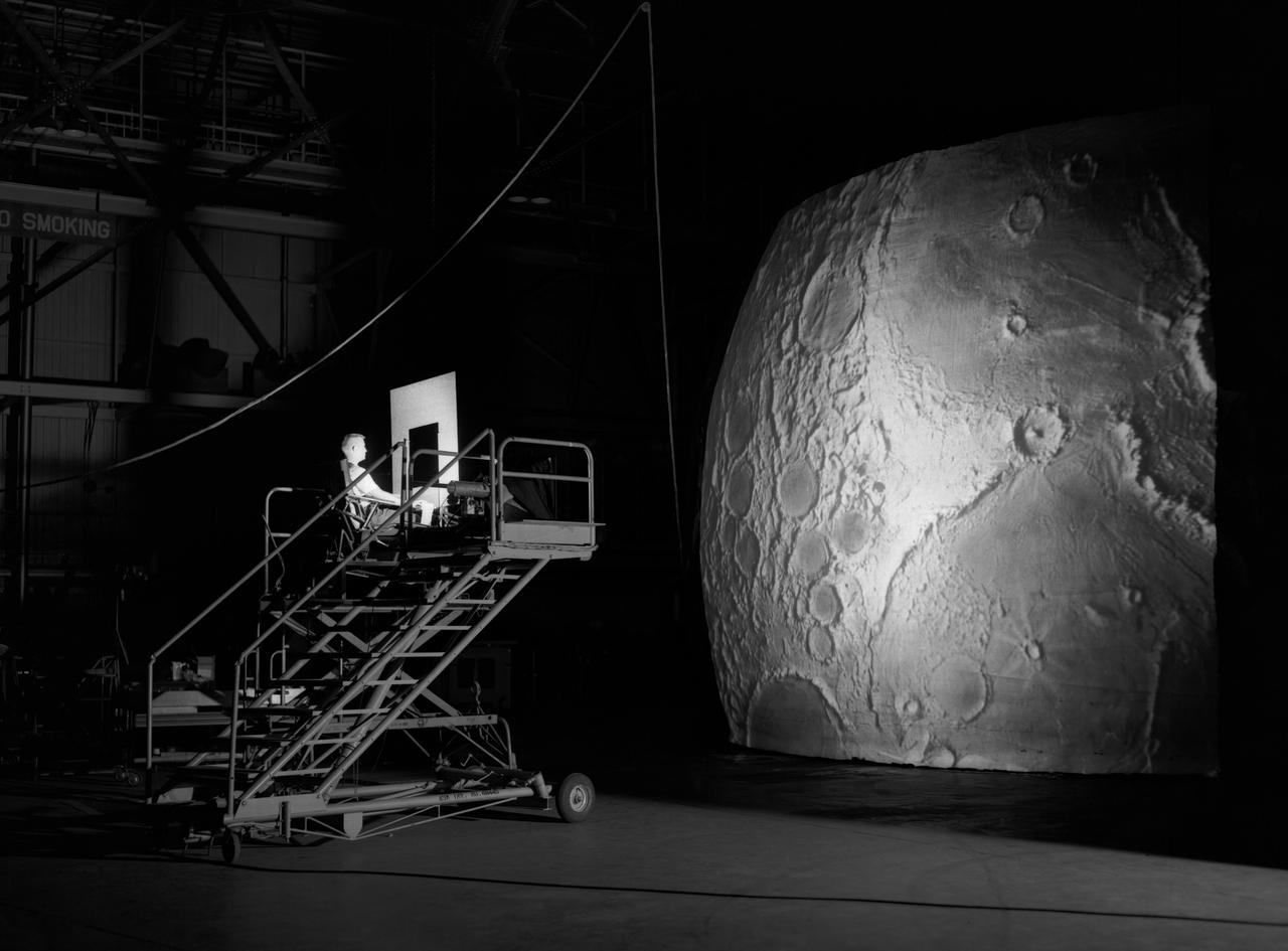
Test subject sitting at the controls: Project LOLA or Lunar Orbit and Landing Approach was a simulator built at Langley to study problems related to landing on the lunar surface. It was a complex project that cost nearly $2 million dollars. James Hansen wrote: "This simulator was designed to provide a pilot with a detailed visual encounter with the lunar surface; the machine consisted primarily of a cockpit, a closed-circuit TV system, and four large murals or scale models representing portions of the lunar surface as seen from various altitudes. The pilot in the cockpit moved along a track past these murals which would accustom him to the visual cues for controlling a spacecraft in the vicinity of the moon. Unfortunately, such a simulation--although great fun and quite aesthetic--was not helpful because flight in lunar orbit posed no special problems other than the rendezvous with the LEM, which the device did not simulate. Not long after the end of Apollo, the expensive machine was dismantled." (p. 379) Ellis J. White further described this simulator in his paper , "Discussion of Three Typical Langley Research Center Simulation Programs," (Paper presented at the Eastern Simulation Council (EAI's Princeton Computation Center), Princeton, NJ, October 20, 1966.) "A typical mission would start with the first cart positioned on model 1 for the translunar approach and orbit establishment. After starting the descent, the second cart is readied on model 2 and, at the proper time, when superposition occurs, the pilot's scene is switched from model 1 to model 2. then cart 1 is moved to and readied on model 3. The procedure continues until an altitude of 150 feet is obtained. The cabin of the LM vehicle has four windows which represent a 45 degree field of view. The projection screens in front of each window represent 65 degrees which allows limited head motion before the edges of the display can be seen. The lunar scene is presented to the pilot by rear projection on the screens with four Schmidt television projectors. The attitude orientation of the vehicle is represented by changing the lunar scene through the portholes determined by the scan pattern of four orthicons. The stars are front projected onto the upper three screens with a four-axis starfield generation (starball) mounted over the cabin and there is a separate starball for the low window." -- Published in James R. Hansen, Spaceflight Revolution: NASA Langley Research Center From Sputnik to Apollo, (Washington: NASA, 1995), p. 379.