Orion's launch abort system separates on its first flight test, Exploration Flight Test-1 (EFT-1), on December 5, 2014.

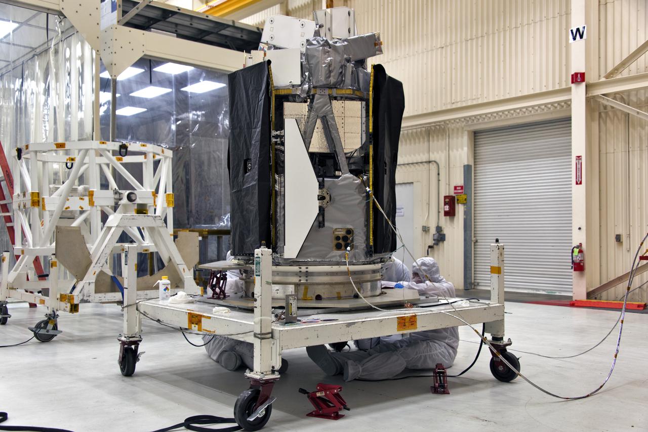
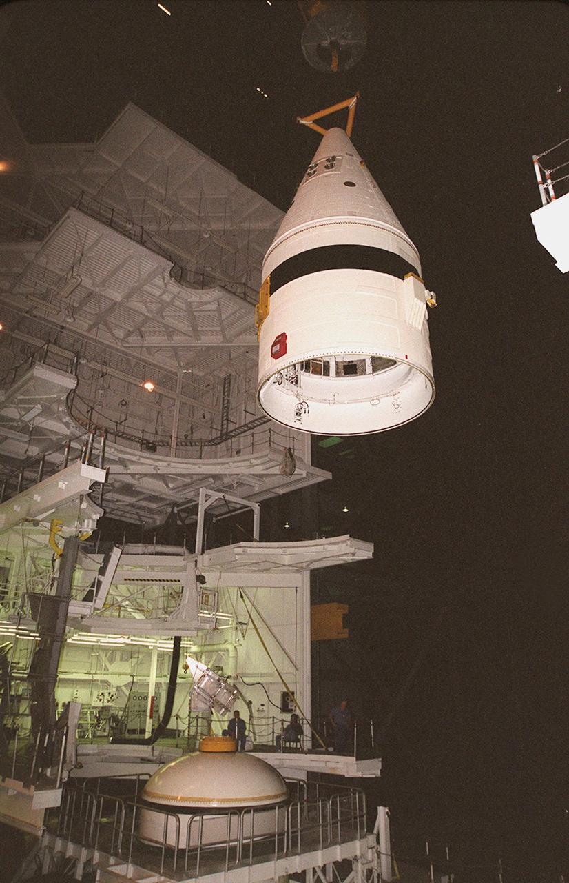
In Building 1555 on North Vandenberg Air Force Base in California, technicians carry the separation system, at left, toward the AIM spacecraft hovering above the stand at right. AIM, which stands for Aeronomy of Ice in the Mesosphere, is being prepared for integrated testing and a flight simulation. The AIM spacecraft will fly three instruments designed to study polar mesospheric clouds located at the edge of space, 50 miles above the Earth's surface in the coldest part of the planet's atmosphere. The mission's primary goal is to explain why these clouds form and what has caused them to become brighter and more numerous and appear at lower latitudes in recent years. AIM's results will provide the basis for the study of long-term variability in the mesospheric climate and its relationship to global climate change. AIM is scheduled to be mated to its launch vehicle, Orbital Sciences' Pegasus XL, during the second week of April, after which final inspections will be conducted. Launch is scheduled for April 25.
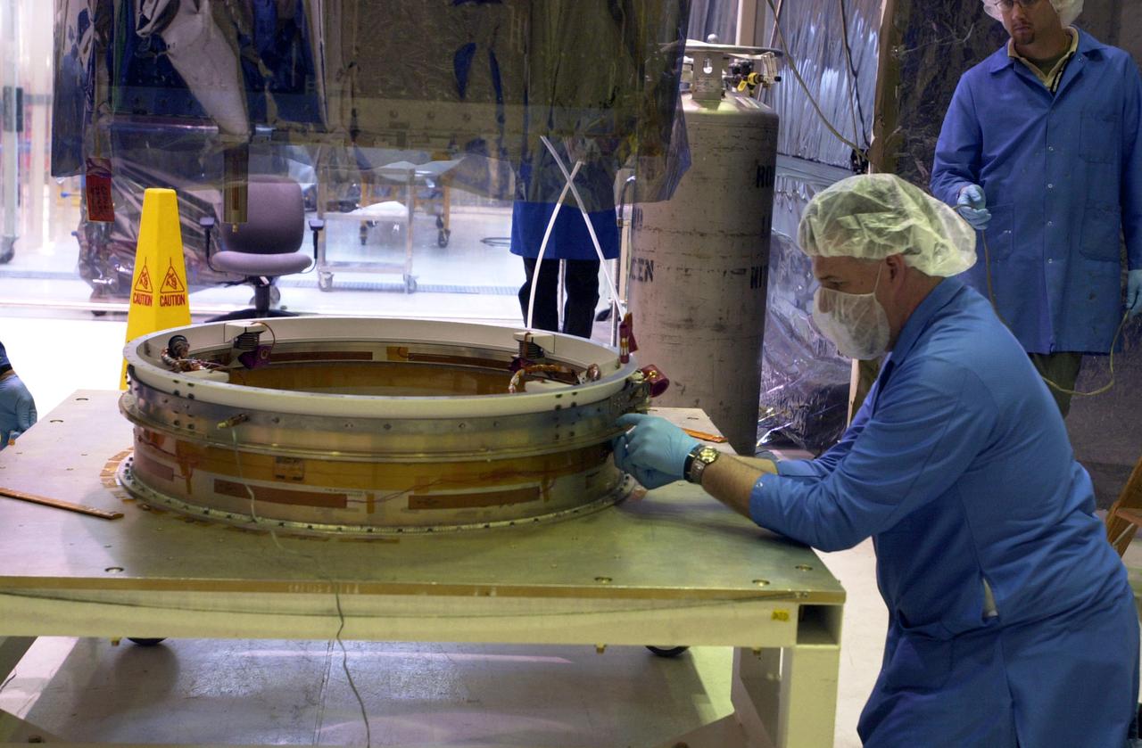
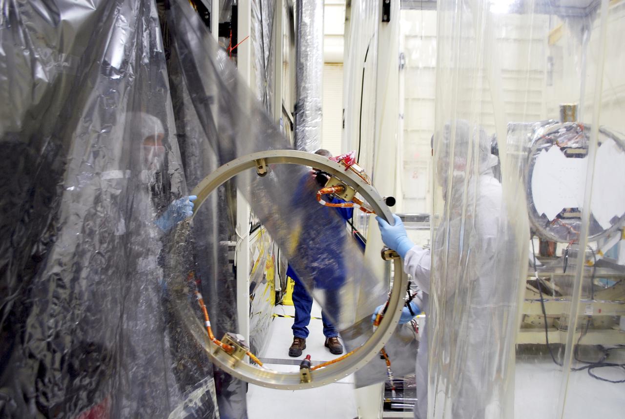
In Building 1555 on North Vandenberg Air Force Base in California, technicians work on the separation system to be mated to the AIM spacecraft, hovering above it. AIM, which stands for Aeronomy of Ice in the Mesosphere, is being prepared for integrated testing and a flight simulation. The AIM spacecraft will fly three instruments designed to study polar mesospheric clouds located at the edge of space, 50 miles above the Earth's surface in the coldest part of the planet's atmosphere. The mission's primary goal is to explain why these clouds form and what has caused them to become brighter and more numerous and appear at lower latitudes in recent years. AIM's results will provide the basis for the study of long-term variability in the mesospheric climate and its relationship to global climate change. AIM is scheduled to be mated to its launch vehicle, Orbital Sciences' Pegasus XL, during the second week of April, after which final inspections will be conducted. Launch is scheduled for April 25.
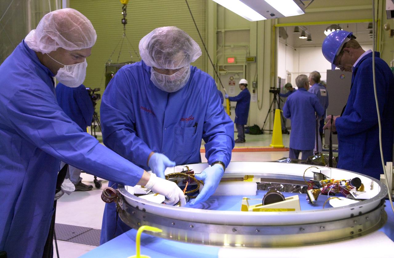
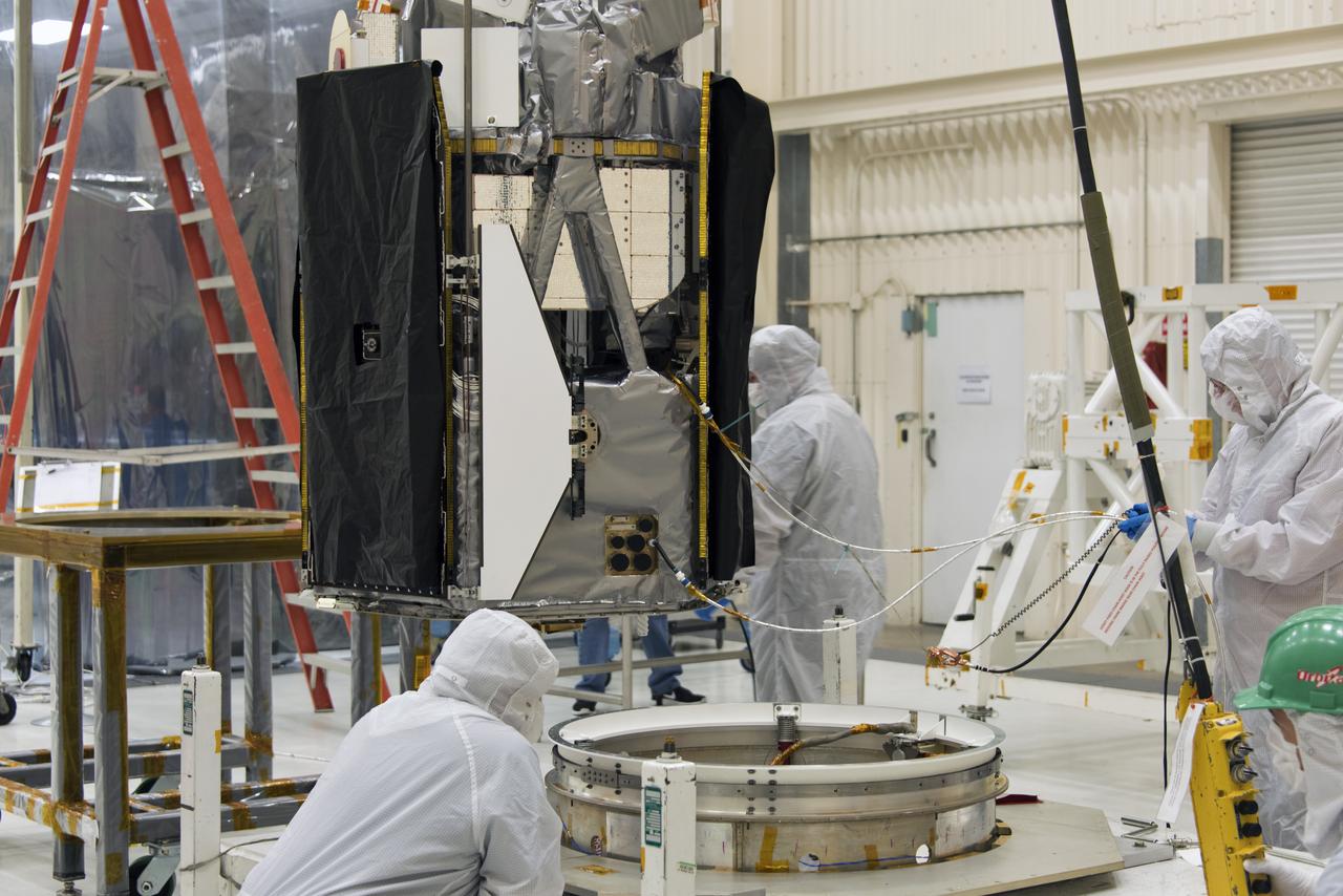
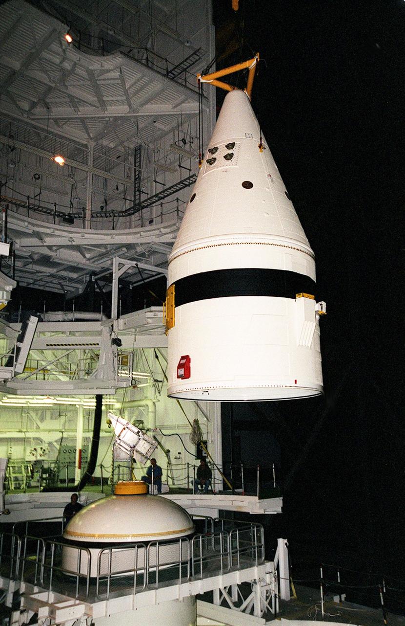
In Building 1555 on North Vandenberg Air Force Base in California, technicians work on the separation system to be mated to the AIM spacecraft. AIM, which stands for Aeronomy of Ice in the Mesosphere, is being prepared for integrated testing and a flight simulation. The AIM spacecraft will fly three instruments designed to study polar mesospheric clouds located at the edge of space, 50 miles above the Earth's surface in the coldest part of the planet's atmosphere. The mission's primary goal is to explain why these clouds form and what has caused them to become brighter and more numerous and appear at lower latitudes in recent years. AIM's results will provide the basis for the study of long-term variability in the mesospheric climate and its relationship to global climate change. AIM is scheduled to be mated to its launch vehicle, Orbital Sciences' Pegasus XL, during the second week of April, after which final inspections will be conducted. Launch is scheduled for April 25.
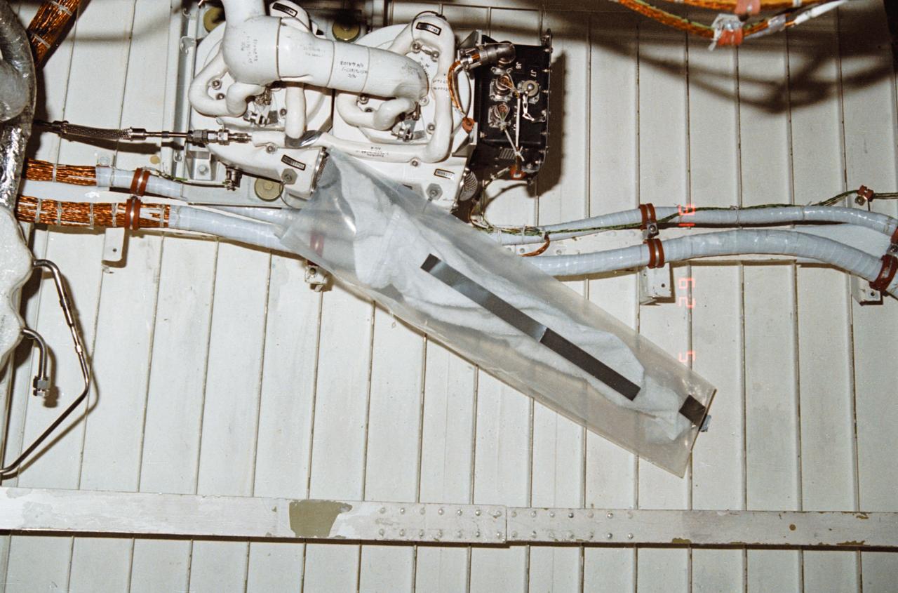
During STS-32, onboard Columbia, Orbiter Vehicle (OV) 102, a leakage problem at environmental control and life support system (ECLSS) air revitalization system (ARS) humidity separator A below the middeck is solved with a plastic bag and a towel. The towel inserted inside a plastic bag absorbed the water that had collected at the separator inlet.
Technicians secure NASA's Ionospheric Connection Explorer (ICON) on the spacecraft separation system May 9, 2018, in a clean room inside Building 1555 at Vandenberg Air Force Base in California. The explorer will launch on June 15, 2018, from Kwajalein Atoll in the Marshall Islands (June 14 in the continental United States) on Orbital ATK's Pegasus XL rocket, which is attached to the company's L-1011 Stargazer aircraft. ICON will study the frontier of space - the dynamic zone high in Earth's atmosphere where terrestrial weather from below meets space weather above. The explorer will help determine the physics of Earth's space environment and pave the way for mitigating its effects on our technology, communications systems and society.
Technicians prepare NASA's Ionospheric Connection Explorer (ICON) to be attached to the spacecraft separation system May 9, 2018, in a clean room inside Building 1555 at Vandenberg Air Force Base in California. The explorer will launch on June 15, 2018, from Kwajalein Atoll in the Marshall Islands (June 14 in the continental United States) on Orbital ATK's Pegasus XL rocket, which is attached to the company's L-1011 Stargazer aircraft. ICON will study the frontier of space - the dynamic zone high in Earth's atmosphere where terrestrial weather from below meets space weather above. The explorer will help determine the physics of Earth's space environment and pave the way for mitigating its effects on our technology, communications systems and society.
In Building 1555 on North Vandenberg Air Force Base in California, technicians prepare the AIM spacecraft for integrated testing and a flight simulation. The AIM spacecraft will fly three instruments designed to study polar mesospheric clouds located at the edge of space, 50 miles above the Earth's surface in the coldest part of the planet's atmosphere. The mission's primary goal is to explain why these clouds form and what has caused them to become brighter and more numerous and appear at lower latitudes in recent years. AIM's results will provide the basis for the study of long-term variability in the mesospheric climate and its relationship to global climate change. AIM is scheduled to be mated to its launch vehicle, Orbital Sciences' Pegasus XL, during the second week of April, after which final inspections will be conducted. Launch is scheduled for April 25.
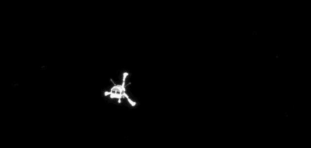
The Onboard Scientific Imaging System OSIRIS on the European Space Agency Rosetta spacecraft captured this parting shot of the mission Philae lander after its separation from the mother ship on Nov. 12, 2014.
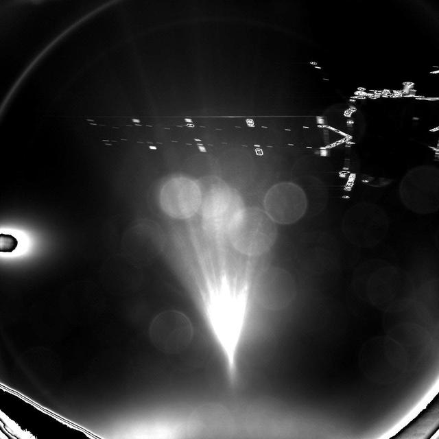
The Philae lander of the European Space Agency Rosetta mission took this parting shot of its mother ship, Rosetta, shortly after separation on Nov. 12, 2014. The image was taken with the lander CIVA-P imaging system.
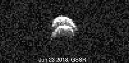
Radar images of the binary asteroid 2017 YE5 from NASA's Goldstone Solar System Radar (GSSR). The observations, conducted on June 23, 2018, show two lobes, but do not yet show two separate objects. A movie is available at https://photojournal.jpl.nasa.gov/catalog/PIA22557
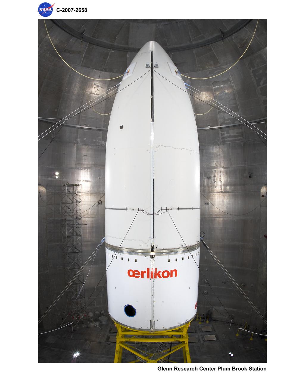
Ariane V Horizontal Separation System 3 (HSS3) Payload Fairing Separation Pre and Post Test Photo Documentation Inside Space Power Facility (SPF)

Composite Art Electro Explusive Separation System (EESS) showing where application would be most effective for deicing and anti-icing
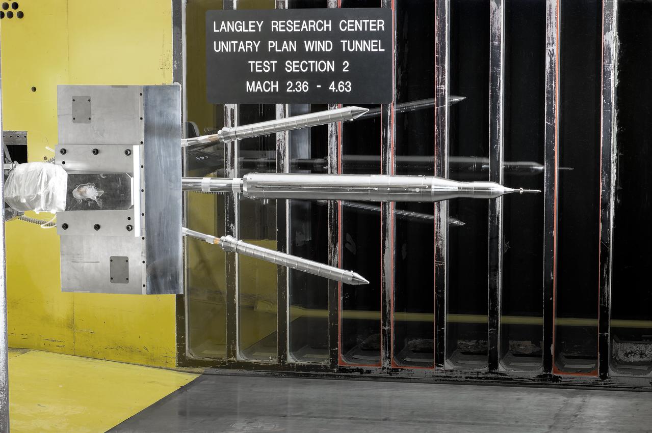
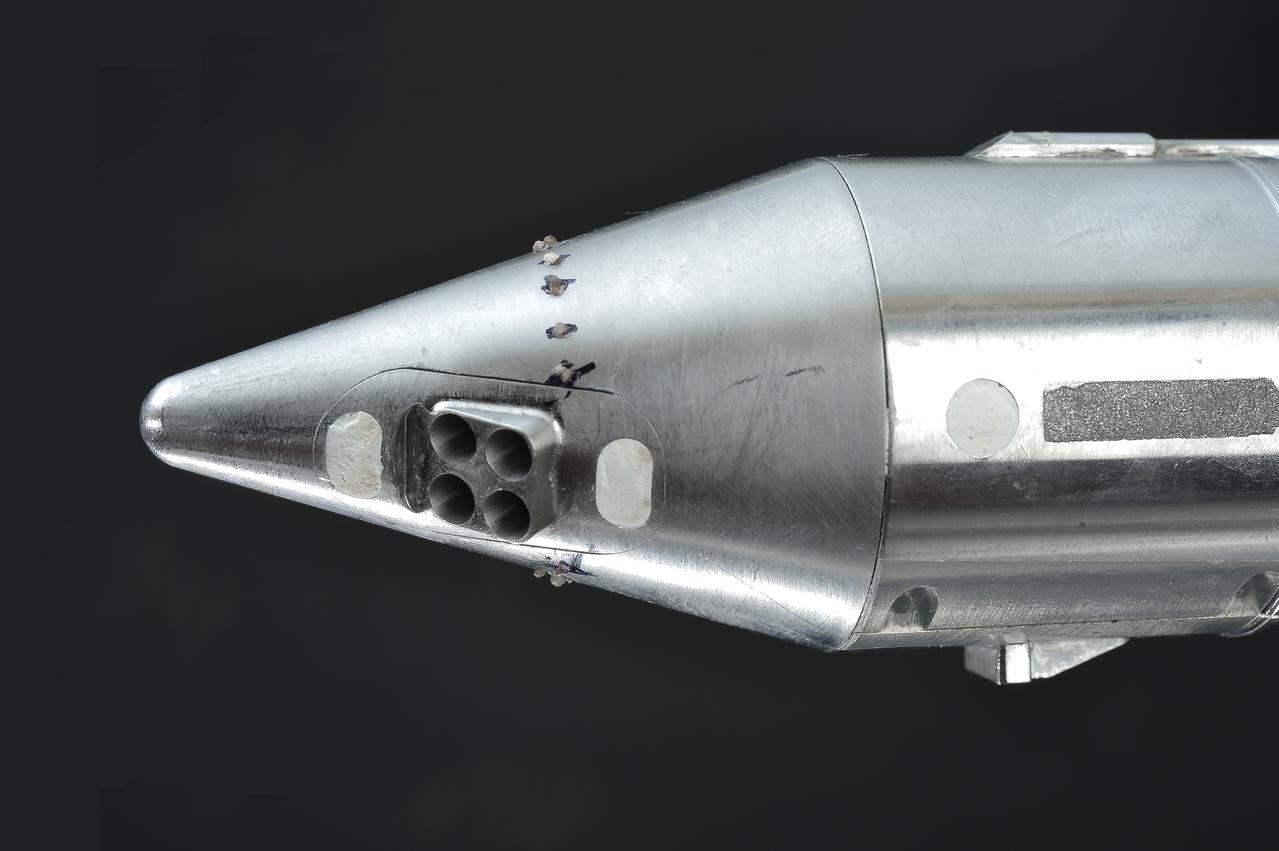
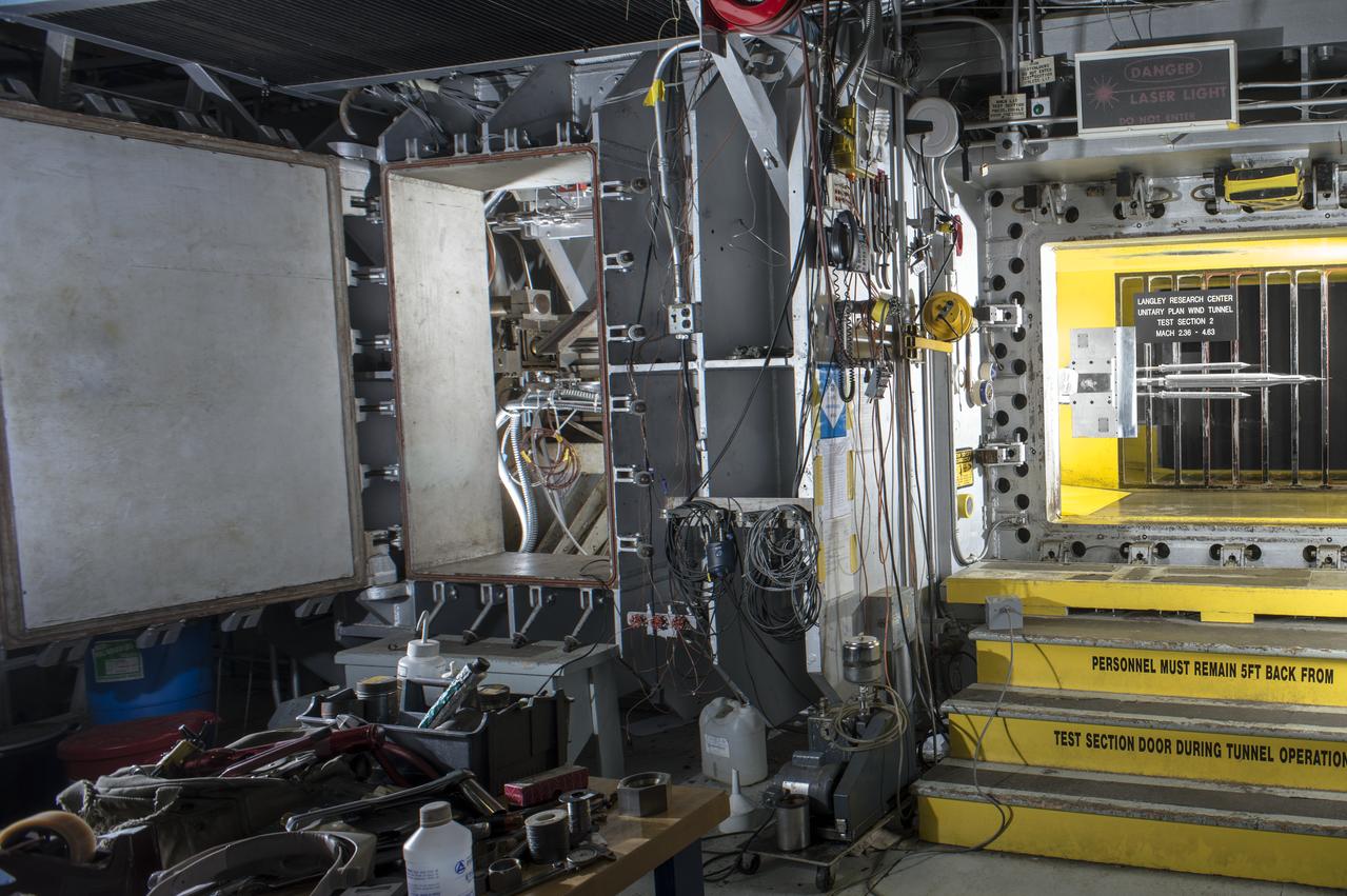
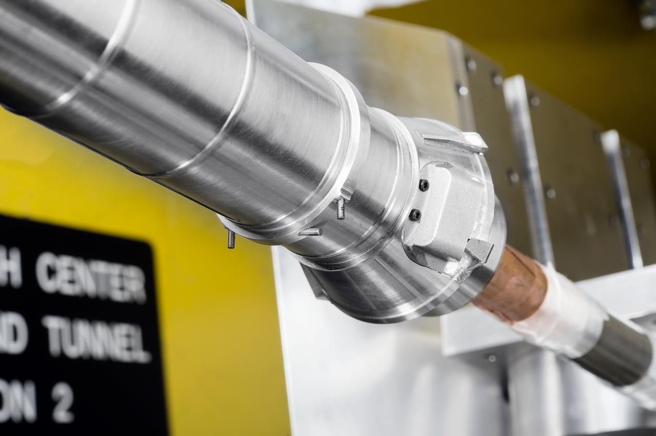
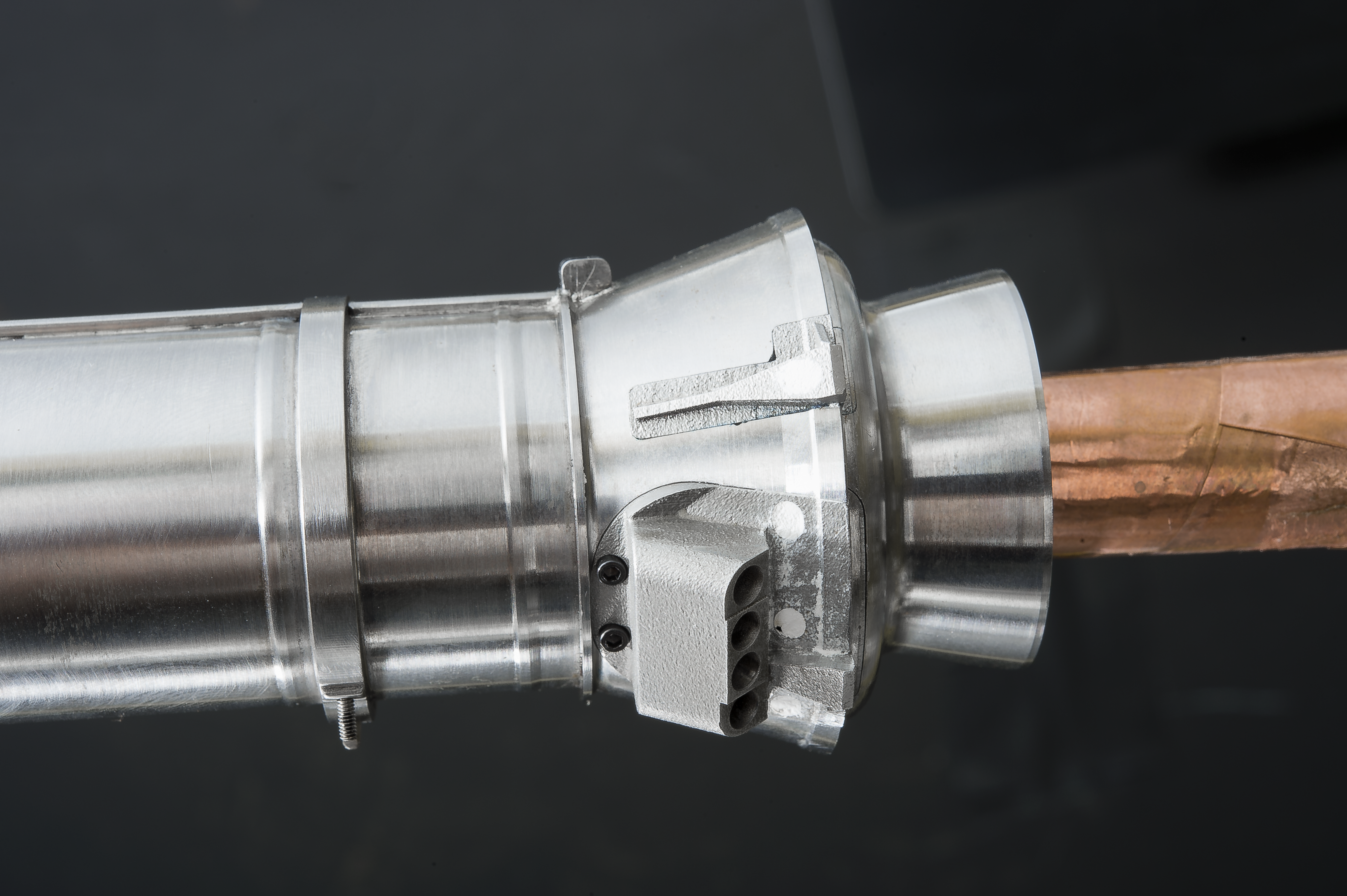
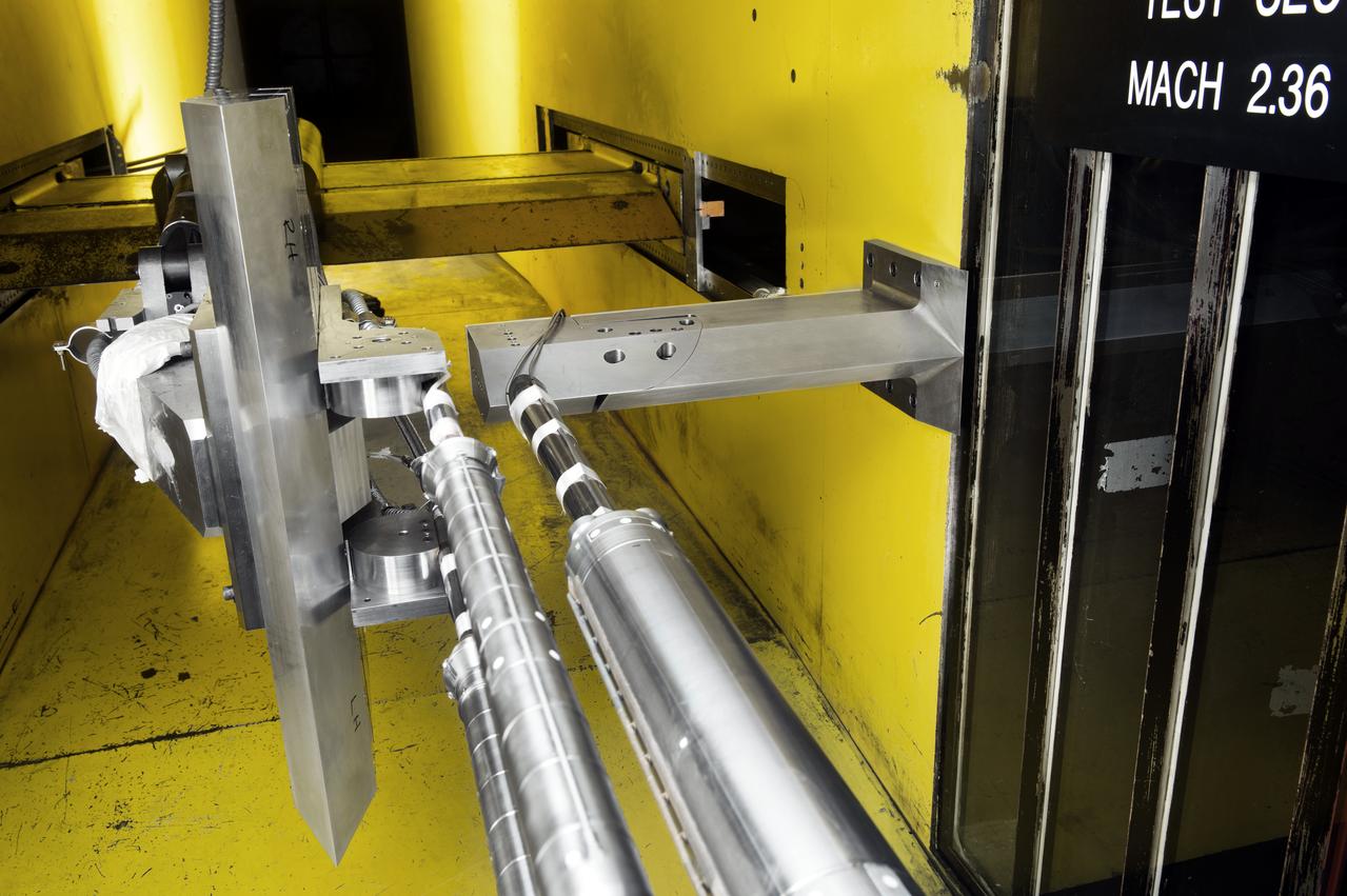
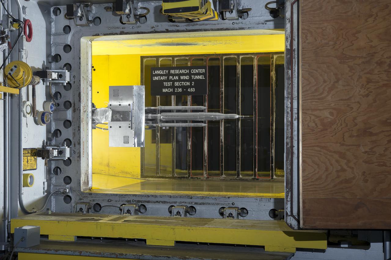
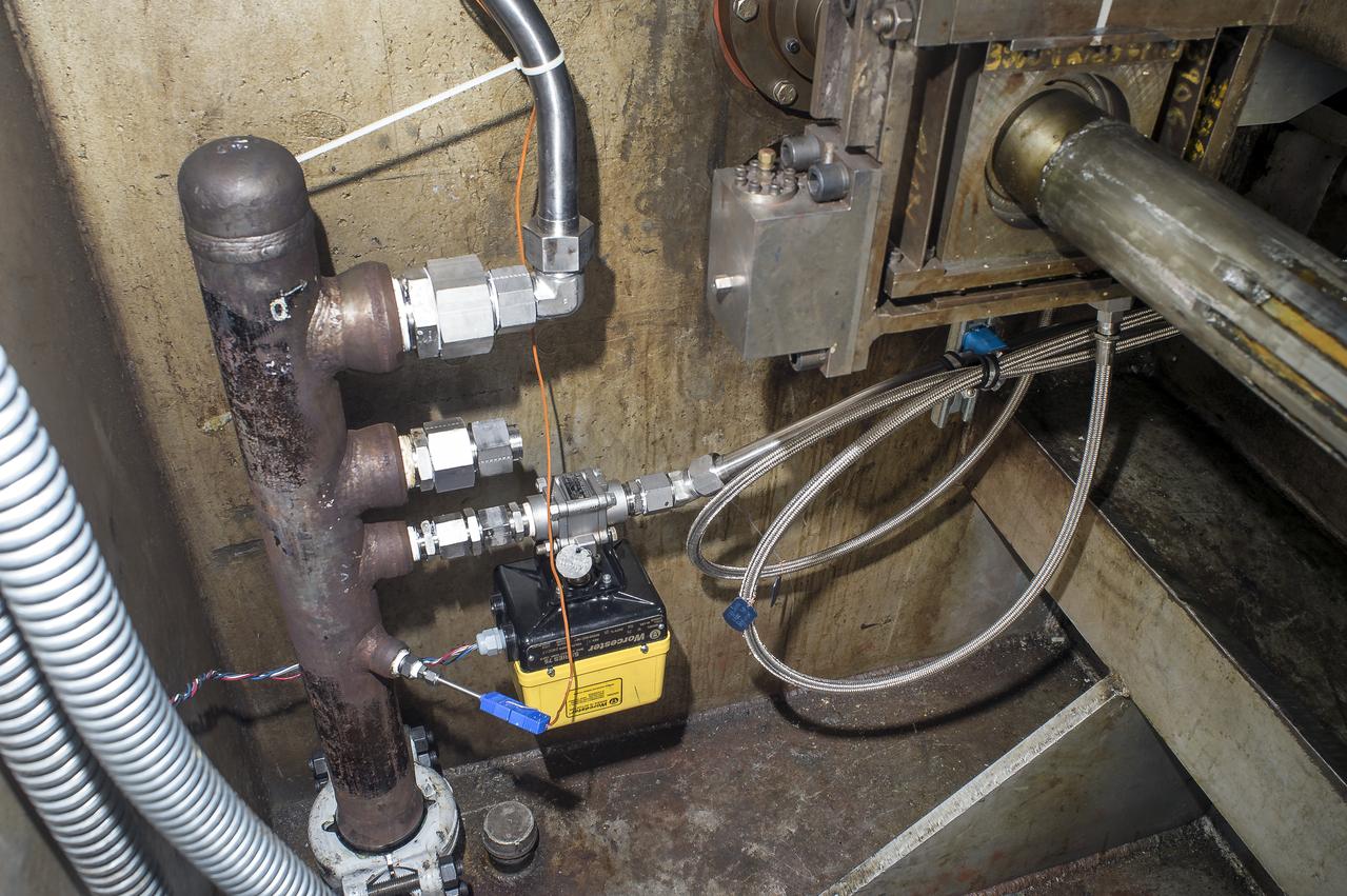
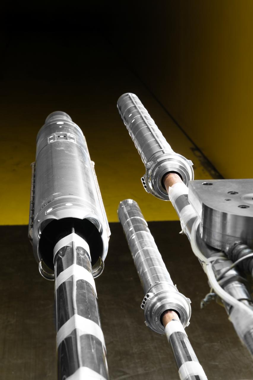
Stage Separation Test of the Space Launch System(SLS) in the Langley Unitary Plan Wind Tunnel (UPWT). The model used High Pressure air blown through the solid rocket boosters. (SRB) to simulate the booster separation motors (BSM) firing.
Stage Separation Test of the Space Launch System(SLS) in the Langley Unitary Plan Wind Tunnel (UPWT). The model used High Pressure air blown through the solid rocket boosters. (SRB) to simulate the booster separation motors (BSM) firing.
Stage Separation Test of the Space Launch System(SLS) in the Langley Unitary Plan Wind Tunnel (UPWT). The model used High Pressure air blown through the solid rocket boosters. (SRB) to simulate the booster separation motors (BSM) firing.
Stage Separation Test of the Space Launch System(SLS) in the Langley Unitary Plan Wind Tunnel (UPWT). The model used High Pressure air blown through the solid rocket boosters. (SRB) to simulate the booster separation motors (BSM) firing.
Stage Separation Test of the Space Launch System(SLS) in the Langley Unitary Plan Wind Tunnel (UPWT). The model used High Pressure air blown through the solid rocket boosters. (SRB) to simulate the booster separation motors (BSM) firing.
Stage Separation Test of the Space Launch System(SLS) in the Langley Unitary Plan Wind Tunnel (UPWT). The model used High Pressure air blown through the solid rocket boosters. (SRB) to simulate the booster separation motors (BSM) firing.
Stage Separation Test of the Space Launch System(SLS) in the Langley Unitary Plan Wind Tunnel (UPWT). The model used High Pressure air blown through the solid rocket boosters. (SRB) to simulate the booster separation motors (BSM) firing.
Stage Separation Test of the Space Launch System(SLS) in the Langley Unitary Plan Wind Tunnel (UPWT). The model used High Pressure air blown through the solid rocket boosters. (SRB) to simulate the booster separation motors (BSM) firing.
Stage Separation Test of the Space Launch System(SLS) in the Langley Unitary Plan Wind Tunnel (UPWT). The model used High Pressure air blown through the solid rocket boosters. (SRB) to simulate the booster separation motors (BSM) firing.

Stage Separation Test of the Space Launch System(SLS) in the Langley Unitary Plan Wind Tunnel (UPWT). The model used High Pressure air blown through the solid rocket boosters. (SRB) to simulate the booster separation motors (BSM) firing.
Stage Separation Test of the Space Launch System(SLS) in the Langley Unitary Plan Wind Tunnel (UPWT). The model used High Pressure air blown through the solid rocket boosters. (SRB) to simulate the booster separation motors (BSM) firing.
Stage Separation Test of the Space Launch System(SLS) in the Langley Unitary Plan Wind Tunnel (UPWT). The model used High Pressure air blown through the solid rocket boosters. (SRB) to simulate the booster separation motors (BSM) firing.
Stage Separation Test of the Space Launch System(SLS) in the Langley Unitary Plan Wind Tunnel (UPWT). The model used High Pressure air blown through the solid rocket boosters. (SRB) to simulate the booster separation motors (BSM) firing.

Stage Separation Test of the Space Launch System(SLS) in the Langley Unitary Plan Wind Tunnel (UPWT). The model used High Pressure air blown through the solid rocket boosters. (SRB) to simulate the booster separation motors (BSM) firing.
Stage Separation Test of the Space Launch System(SLS) in the Langley Unitary Plan Wind Tunnel (UPWT). The model used High Pressure air blown through the solid rocket boosters. (SRB) to simulate the booster separation motors (BSM) firing.
Stage Separation Test of the Space Launch System(SLS) in the Langley Unitary Plan Wind Tunnel (UPWT). The model used High Pressure air blown through the solid rocket boosters. (SRB) to simulate the booster separation motors (BSM) firing.
Stage Separation Test of the Space Launch System(SLS) in the Langley Unitary Plan Wind Tunnel (UPWT). The model used High Pressure air blown through the solid rocket boosters. (SRB) to simulate the booster separation motors (BSM) firing.
Stage Separation Test of the Space Launch System(SLS) in the Langley Unitary Plan Wind Tunnel (UPWT). The model used High Pressure air blown through the solid rocket boosters. (SRB) to simulate the booster separation motors (BSM) firing.
Stage Separation Test of the Space Launch System(SLS) in the Langley Unitary Plan Wind Tunnel (UPWT). The model used High Pressure air blown through the solid rocket boosters. (SRB) to simulate the booster separation motors (BSM) firing.
Stage Separation Test of the Space Launch System(SLS) in the Langley Unitary Plan Wind Tunnel (UPWT). The model used High Pressure air blown through the solid rocket boosters. (SRB) to simulate the booster separation motors (BSM) firing.
Stage Separation Test of the Space Launch System(SLS) in the Langley Unitary Plan Wind Tunnel (UPWT). The model used High Pressure air blown through the solid rocket boosters. (SRB) to simulate the booster separation motors (BSM) firing.
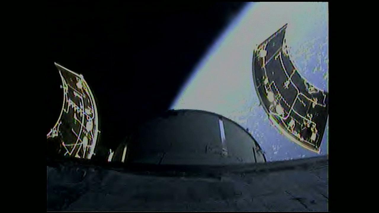
An onboard camera captures separation of the three 13 by 14-foot Orion service module fairings following lift off the Delta IV Heavy rocket from Space Launch Complex 37 at Cape Canaveral Air Force Station in Florida on Dec. 5, 2014. Exploration Flight Test-1 (EFT-1) also will validate systems such as Orion’s parachutes, avionics and attitude control, and demonstrate major separation events such as the launch abort system jettison and the service module fairing separation. Part of Batch image transfer from Flickr.
The ADvanced SEParation (ADSEP) commercial payload is making use of major advances in separation technology: The Phase Partitioning Experiment (PPE); the Micorencapsulation experiment; and the Hemoglobin Separation Experiment (HSE). Using ADSEP, commercial researchers will attempt to determine the partition coefficients for model particles in a two-phase system. With this information, researchers can develop a higher resolution, more effective cell isolation procedure that can be used for many different types of research and for improved health care. The advanced separation technology is already being made available for use in ground-based laboratories.
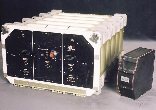
The ADvanced SEParation (ADSEP) commercial payload is making use of major advances in separation technology: The Phase Partitioning Experiment (PPE); the Micorencapsulation experiment; and the Hemoglobin Separation Experiment (HSE). Using ADSEP, commercial researchers will attempt to determine the partition coefficients for model particles in a two-phase system. With this information, researchers can develop a higher resolution, more effective cell isolation procedure that can be used for many different types of research and for improved health care. The advanced separation technology is already being made available for use in ground-based laboratories.
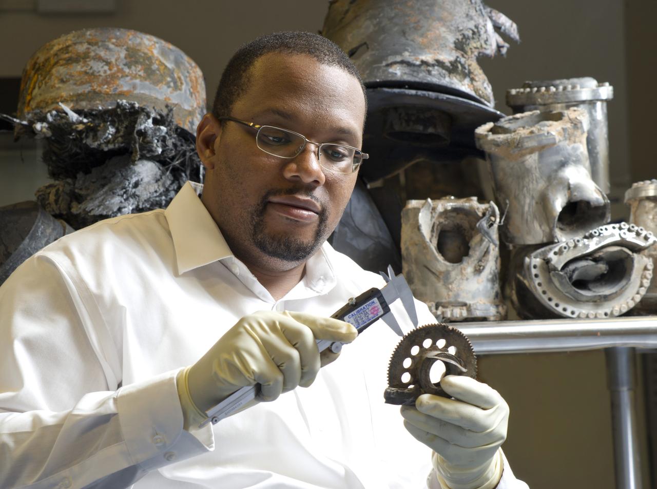
MARVIN BARNES, NASA MSFC ER52 SOLID PROPULSION, SEPARATION AND MANEUVERING SYSTEMS BRANCH, INSPECTS POST-FLIGHT ORION LAUNCH ABORT SYSTEM (LAS) PAD ABORT 1 (PA-1) HARDWARE
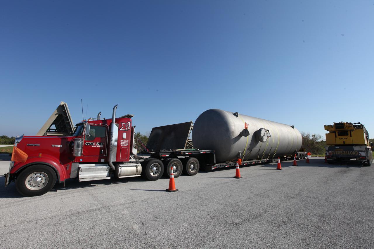
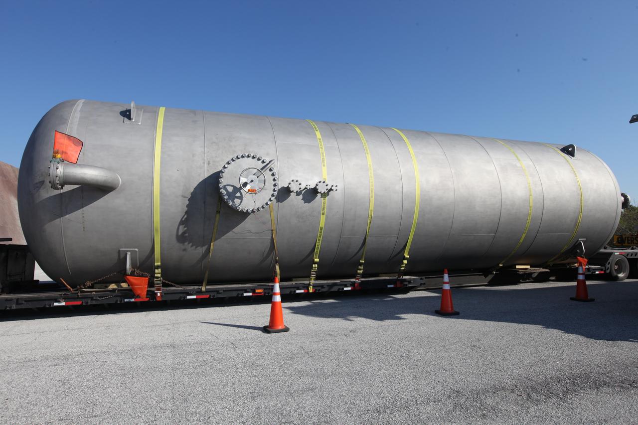
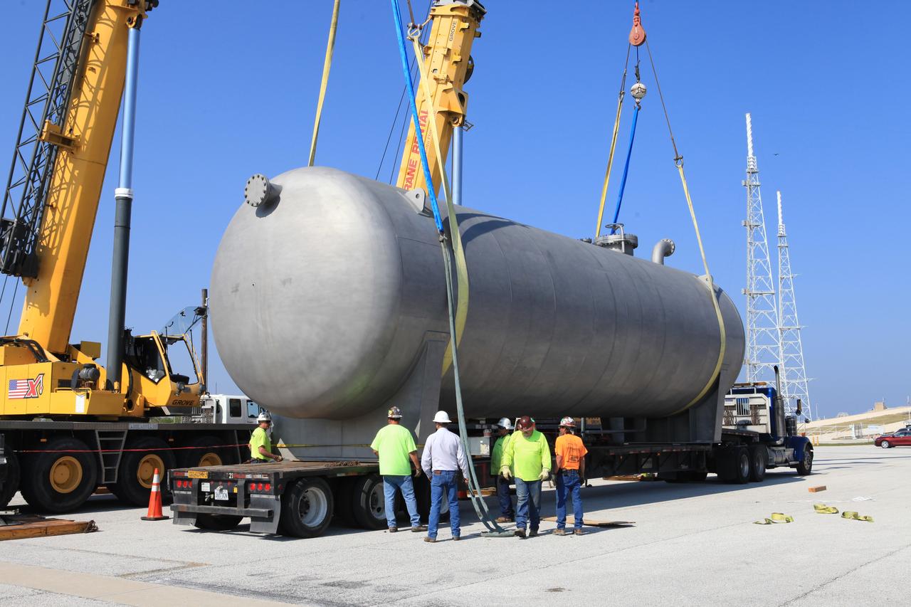
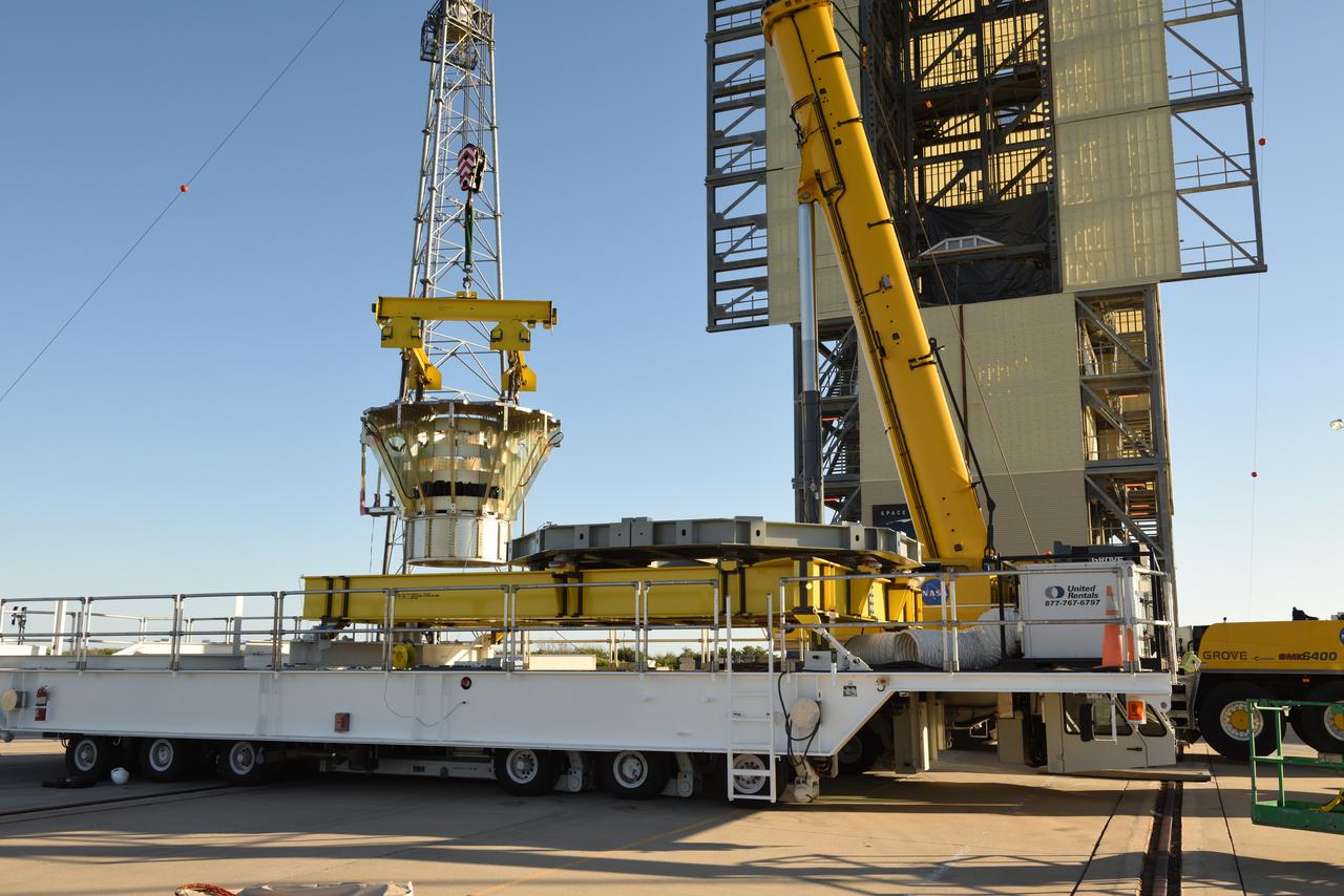
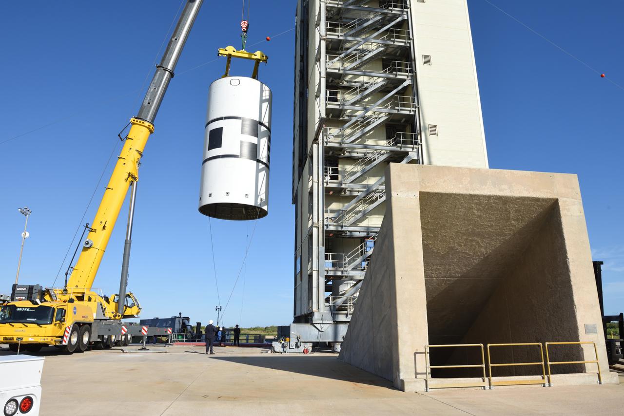
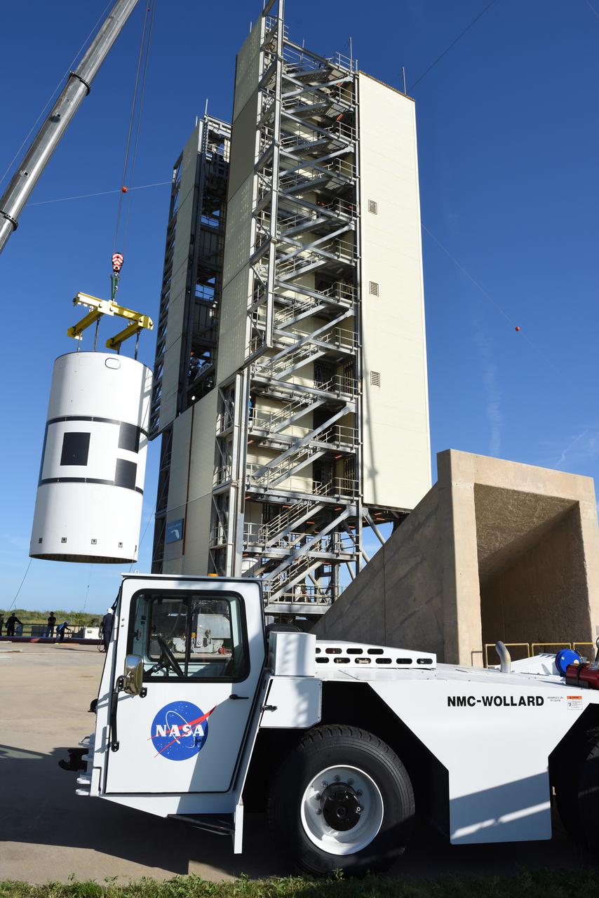
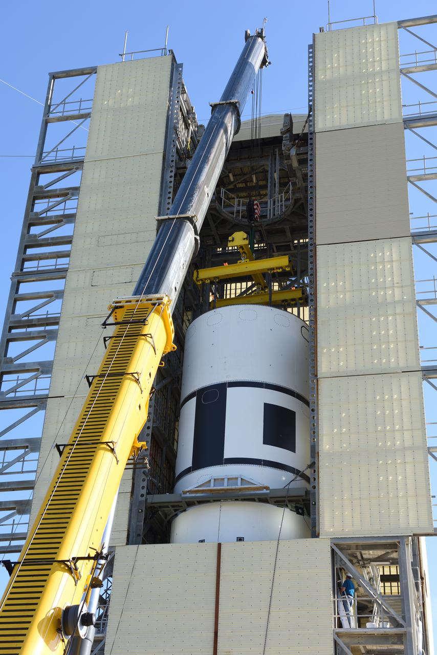
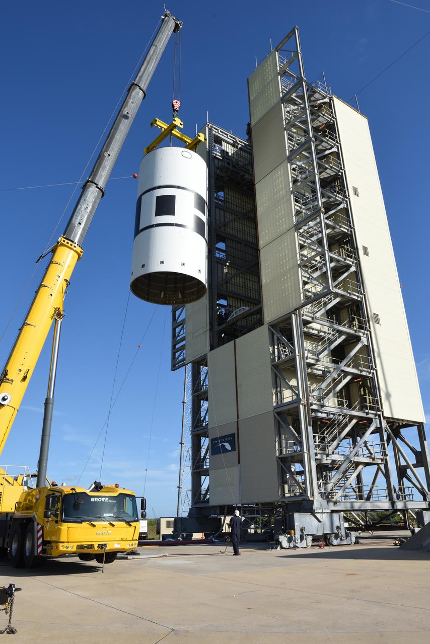
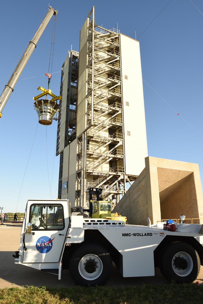
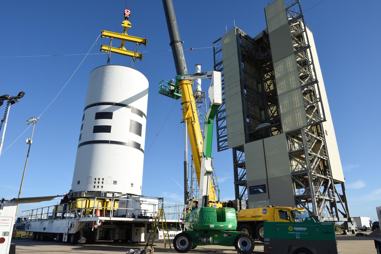
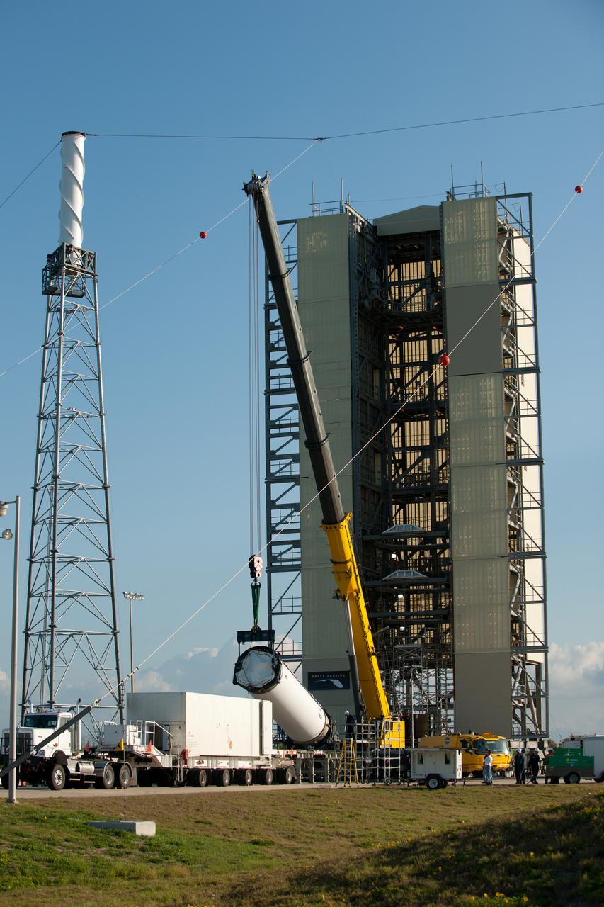
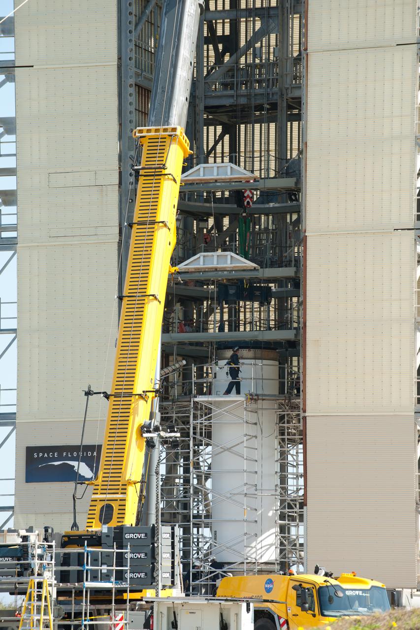
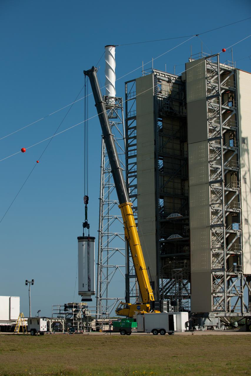
A new liquid hydrogen separator tank arrives at NASA's Kennedy Space Center in Florida. The tank will be lifted and rotated for delivery to Launch Pad 39B. The new separator/storage tank will be added to the pad's existing hydrogen vent system to assure gaseous hydrogen is delivered downstream to the flare stack. The 60,000 gallon tank was built by INOXCVA, in Baytown, Texas, a subcontractor of Precision Mechanical Inc. in Cocoa Florida. The new tank will support all future launches from the pad.
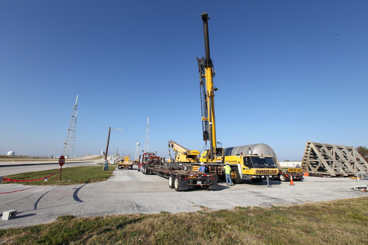
A new liquid hydrogen separator tank arrives at NASA's Kennedy Space Center in Florida. A crane will be used to lift and rotate the tank for delivery to Launch Pad 39B. The new separator/storage tank will be added to the pad's existing hydrogen vent system to assure gaseous hydrogen is delivered downstream to the flare stack. The 60,000 gallon tank was built by INOXCVA, in Baytown, Texas, a subcontractor of Precision Mechanical Inc. in Cocoa Florida. The new tank will support all future launches from the pad.
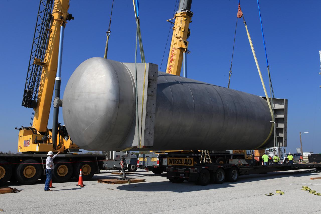
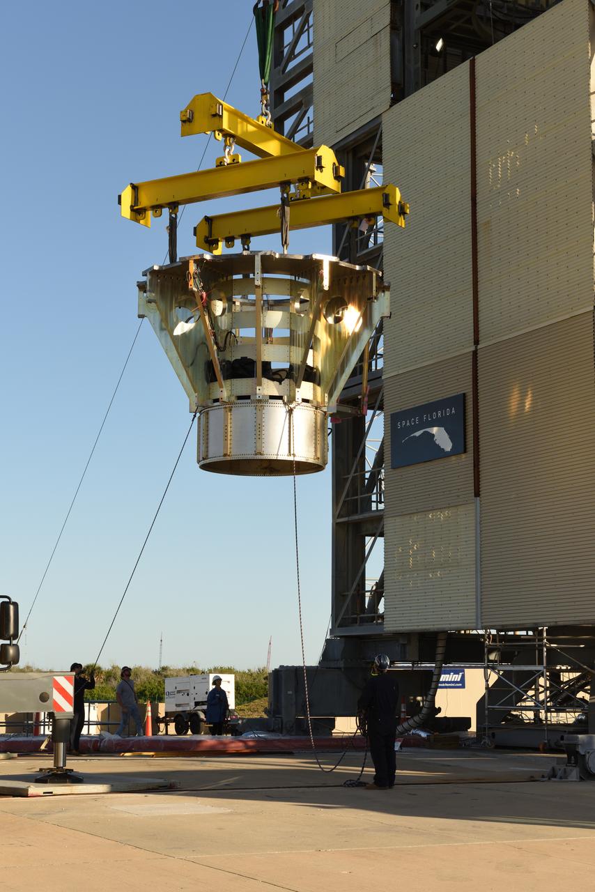
A new liquid hydrogen separator tank arrives at NASA's Kennedy Space Center in Florida. A crane has been attached to the tank to lift and rotate it before it is delivered to Launch Pad 39B. The new separator/storage tank will be added to the pad's existing hydrogen vent system to assure gaseous hydrogen is delivered downstream to the flare stack. The 60,000 gallon tank was built by INOXCVA, in Baytown, Texas, a subcontractor of Precision Mechanical Inc. in Cocoa Florida. The new tank will support all future launches from the pad.
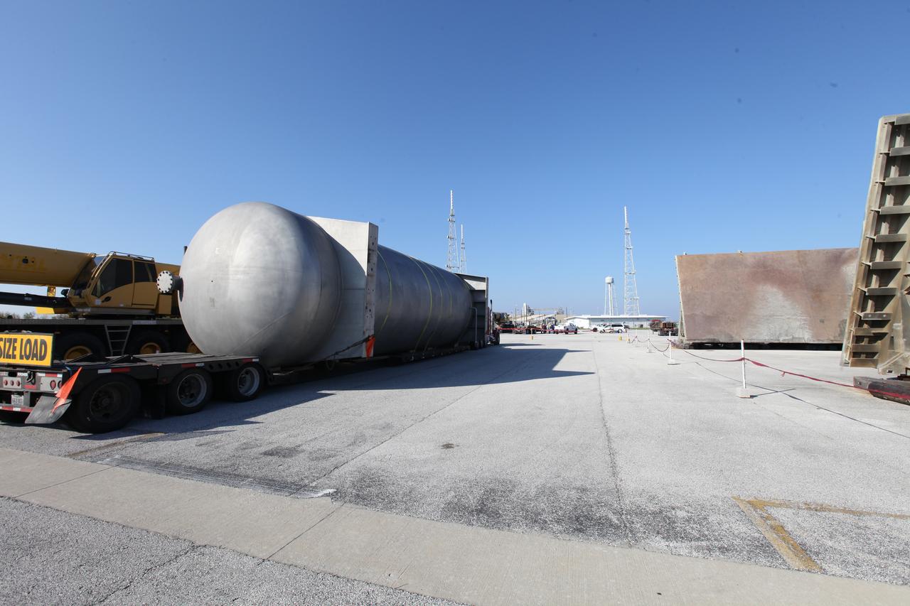
A new liquid hydrogen separator tank arrives at NASA's Kennedy Space Center in Florida. The tank will be lifted and rotated for delivery to Launch Pad 39B. The new separator/storage tank will be added to the pad's existing hydrogen vent system to assure gaseous hydrogen is delivered downstream to the flare stack. The 60,000 gallon tank was built by INOXCVA, in Baytown, Texas, a subcontractor of Precision Mechanical Inc. in Cocoa Florida. The new tank will support all future launches from the pad.
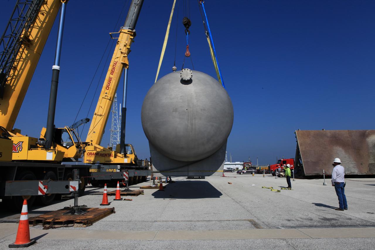
A new liquid hydrogen separator tank arrives at NASA's Kennedy Space Center in Florida. A crane is used to lift and rotate the tank before it is delivered to Launch Pad 39B. The new separator/storage tank will be added to the pad's existing hydrogen vent system to assure gaseous hydrogen is delivered downstream to the flare stack. The 60,000 gallon tank was built by INOXCVA, in Baytown, Texas, a subcontractor of Precision Mechanical Inc. in Cocoa Florida. The new tank will support all future launches from the pad.
A new liquid hydrogen separator tank arrives at NASA's Kennedy Space Center in Florida. The tank will be lifted and rotated for delivery to Launch Pad 39B. The new separator/storage tank will be added to the pad's existing hydrogen vent system to assure gaseous hydrogen is delivered downstream to the flare stack. The 60,000 gallon tank was built by INOXCVA, in Baytown, Texas, a subcontractor of Precision Mechanical Inc. in Cocoa Florida. The new tank will support all future launches from the pad.
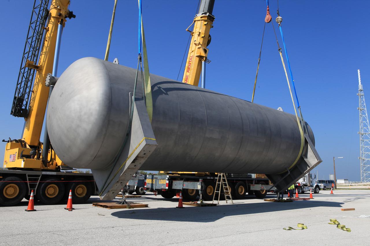
A new liquid hydrogen separator tank arrives at NASA's Kennedy Space Center in Florida. A crane is used to lift the tank and rotate it before it is delivered to Launch Pad 39B. The new separator/storage tank will be added to the pad's existing hydrogen vent system to assure gaseous hydrogen is delivered downstream to the flare stack. The 60,000 gallon tank was built by INOXCVA, in Baytown, Texas, a subcontractor of Precision Mechanical Inc. in Cocoa Florida. The new tank will support all future launches from the pad.
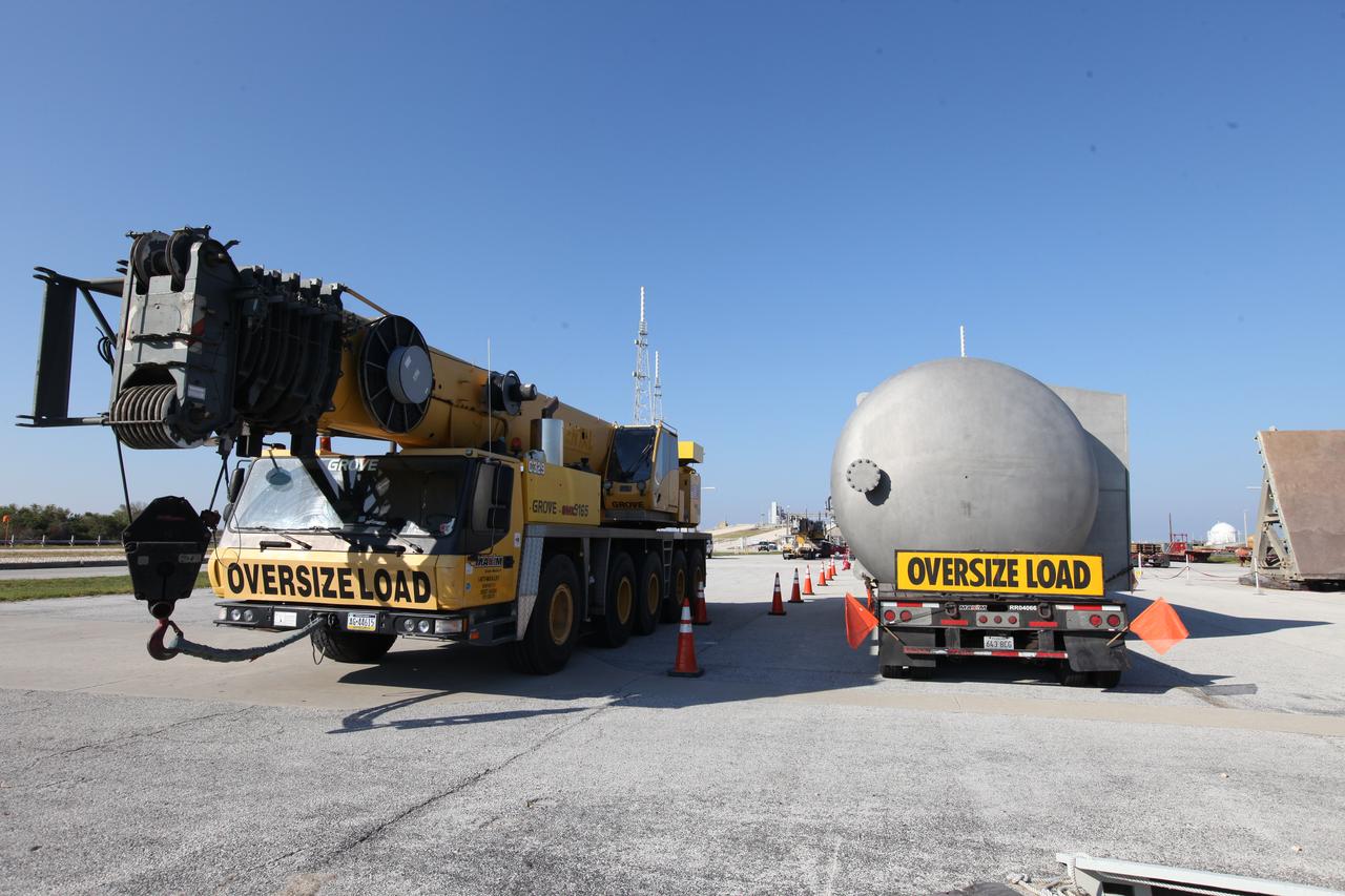
A new liquid hydrogen separator tank arrives at NASA's Kennedy Space Center in Florida. A crane will be used to lift and rotate the tank for delivery to Launch Pad 39B. The new separator/storage tank will be added to the pad's existing hydrogen vent system to assure gaseous hydrogen is delivered downstream to the flare stack. The 60,000 gallon tank was built by INOXCVA, in Baytown, Texas, a subcontractor of Precision Mechanical Inc. in Cocoa Florida. The new tank will support all future launches from the pad.
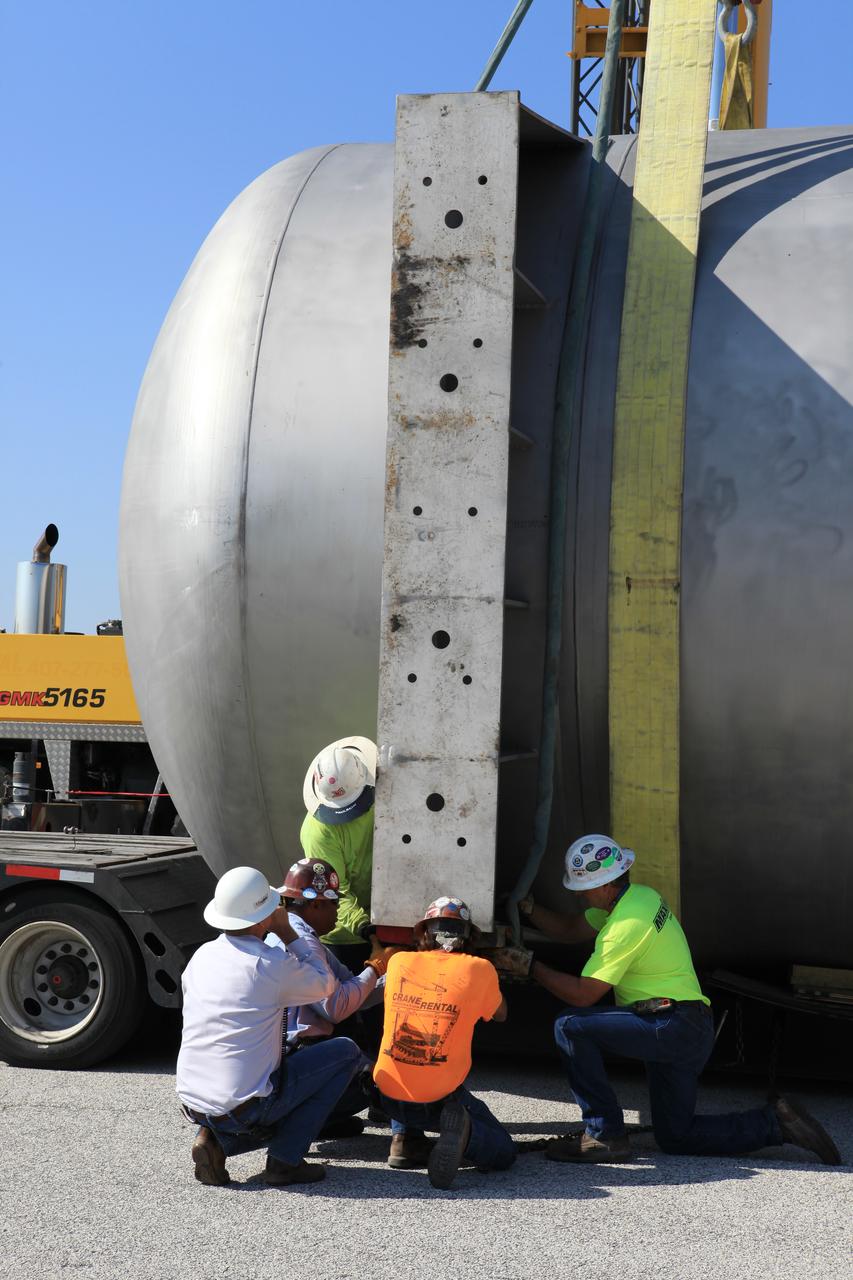
A new liquid hydrogen separator tank arrives at NASA's Kennedy Space Center in Florida. Construction workers check lines as a crane is attached to the tank to lift and rotate it before it is delivered to Launch Pad 39B. The new separator/storage tank will be added to the pad's existing hydrogen vent system to assure gaseous hydrogen is delivered downstream to the flare stack. The 60,000 gallon tank was built by INOXCVA, in Baytown, Texas, a subcontractor of Precision Mechanical Inc. in Cocoa Florida. The new tank will support all future launches from the pad.
A new liquid hydrogen separator tank arrives at NASA's Kennedy Space Center in Florida. A crane is used to lift and rotate the tank before delivery to Launch Pad 39B. The new separator/storage tank will be added to the pad's existing hydrogen vent system to assure gaseous hydrogen is delivered downstream to the flare stack. The 60,000 gallon tank was built by INOXCVA, in Baytown, Texas, a subcontractor of Precision Mechanical Inc. in Cocoa Florida. The new tank will support all future launches from the pad.
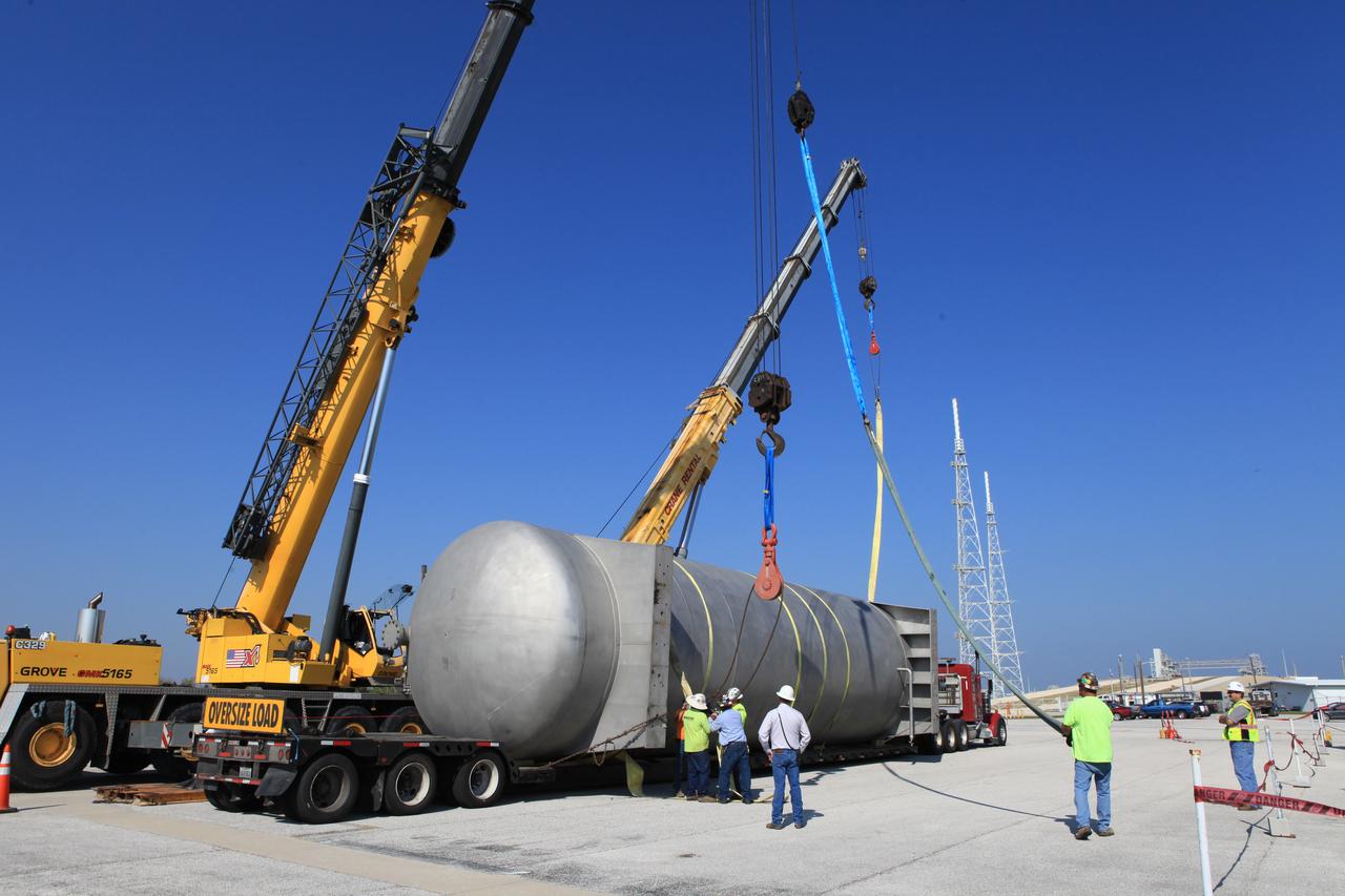
A new liquid hydrogen separator tank arrives at NASA's Kennedy Space Center in Florida. The tank has been lifted and rotated by crane and lowered back onto the flatbed truck for transport to Launch Pad 39B. The new separator/storage tank will be added to the pad's existing hydrogen vent system to assure gaseous hydrogen is delivered downstream to the flare stack. The 60,000 gallon tank was built by INOXCVA, in Baytown, Texas, a subcontractor of Precision Mechanical Inc. in Cocoa Florida. The new tank will support all future launches from the pad.
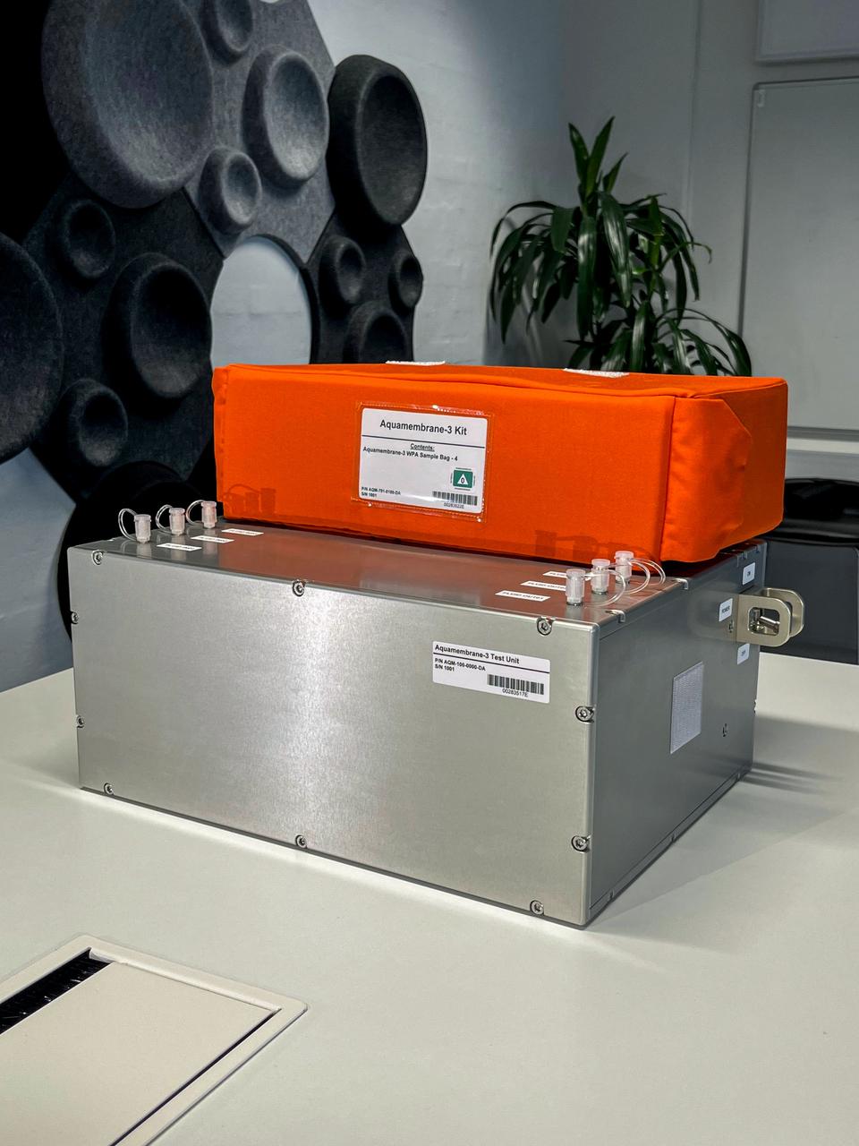
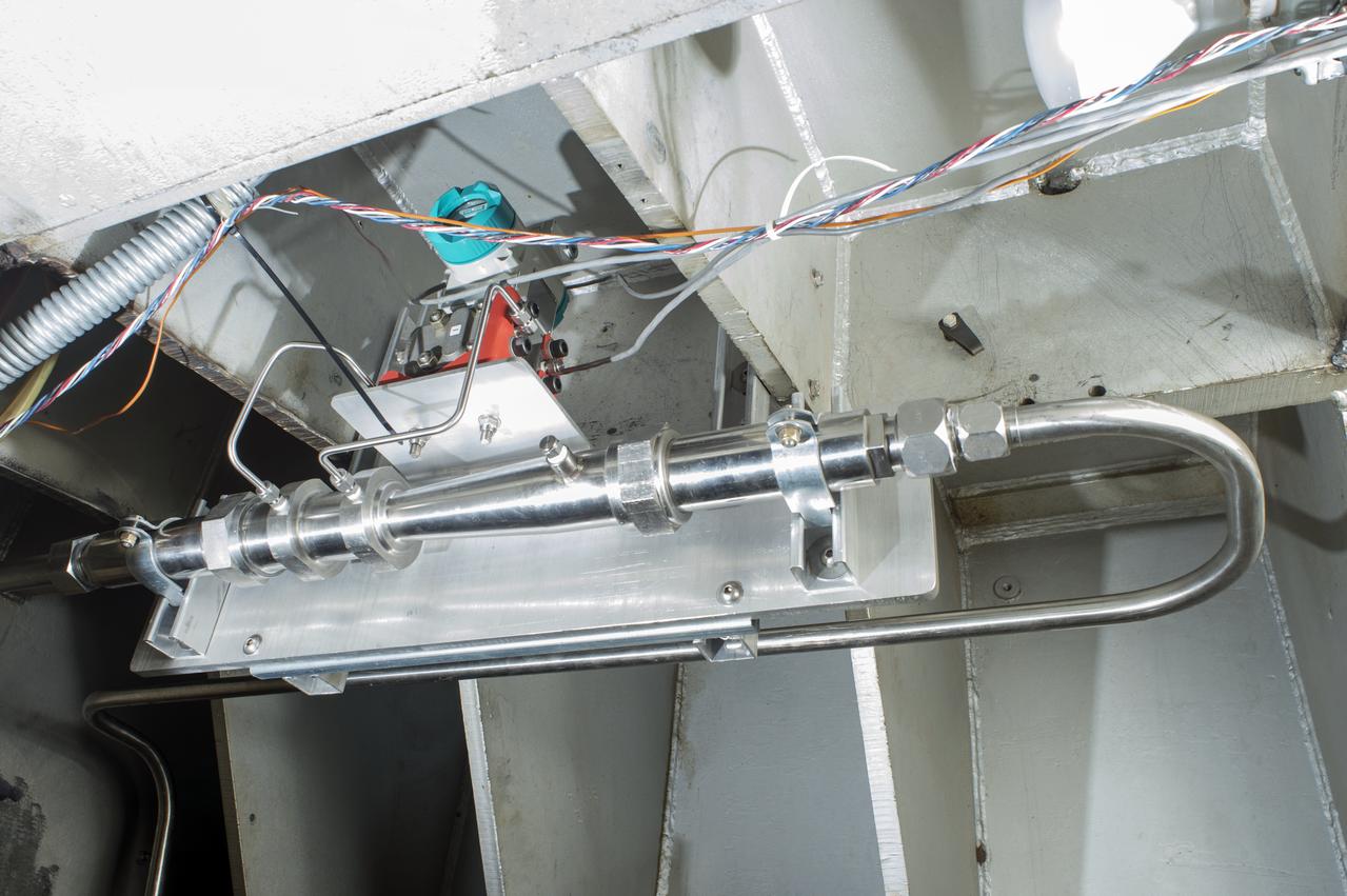
jsc2023e055872 (10/5/2023) --- The Testing Contaminant Rejection of Aquaporin Inside® HFFO Module (Aquamembrane-3) hardware consists of three separate and parallel systems to quantify the membrane's water flux and contamination rejection in microgravity, which are key parameters for a full water recovery system. This image shows the complete experiment hardware.
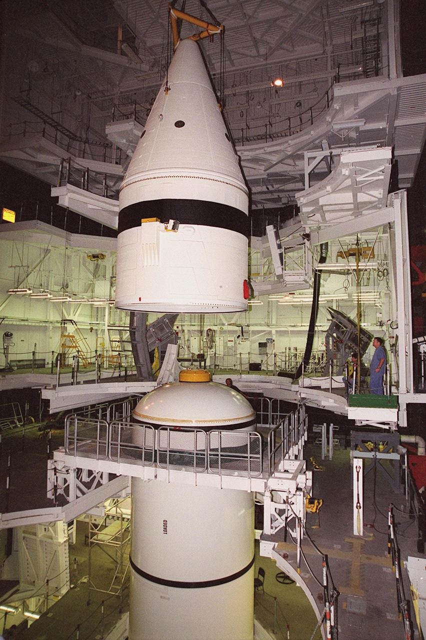
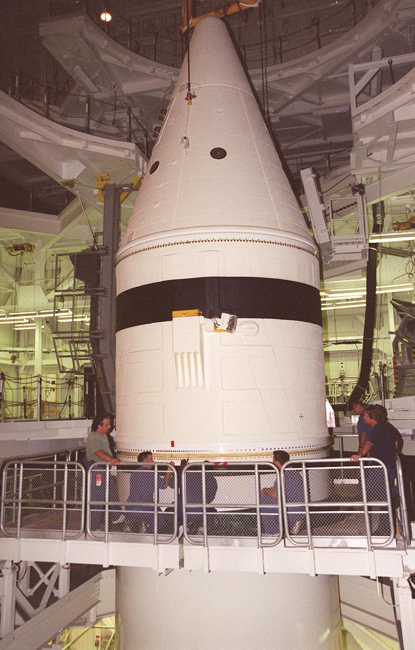
Inside the Vehicle Assembly Building, an overhead crane lifts the forward section of a solid rocket booster (SRB) to mate it with the components seen at lower left in the photo. The forward section of each booster, from nose cap to forward skirt contains avionics, a sequencer, forward separation motors, a nose cone separation system, drogue and main parachutes, a recovery beacon, a recovery light, a parachute camera on selected flights and a range safety system. Each SRB weighs approximately 1.3 million pounds at launch. The SRB is part of the stack for Space Shuttle Discovery and the STS-92 mission, scheduled for launch Oct. 5, from Launch Pad 39A, on the fifth flight to the International Space Station

Inside the Vehicle Assembly Building, an overhead crane lifts the forward section of a solid rocket booster (SRB) to mate it with the components seen at lower left in the photo. The forward section of each booster, from nose cap to forward skirt contains avionics, a sequencer, forward separation motors, a nose cone separation system, drogue and main parachutes, a recovery beacon, a recovery light, a parachute camera on selected flights and a range safety system. Each SRB weighs approximately 1.3 million pounds at launch. The SRB is part of the stack for Space Shuttle Discovery and the STS-92 mission, scheduled for launch Oct. 5, from Launch Pad 39A, on the fifth flight to the International Space Station
Inside the Vehicle Assembly Building, an overhead crane moves the forward section of a solid rocket booster (SRB) toward the previously stacked elements at lower left in the photo. The forward section of each booster, from nose cap to forward skirt contains avionics, a sequencer, forward separation motors, a nose cone separation system, drogue and main parachutes, a recovery beacon, a recovery light, a parachute camera on selected flights and a range safety system. Each SRB weighs approximately 1.3 million pounds at launch. The SRB is part of the stack for Space Shuttle Discovery and the STS-92 mission, scheduled for launch Oct. 5, from Launch Pad 39A, on the fifth flight to the International Space Station

Inside the Vehicle Assembly Building, an overhead crane moves the forward section of a solid rocket booster (SRB) toward the previously stacked elements at lower left in the photo. The forward section of each booster, from nose cap to forward skirt contains avionics, a sequencer, forward separation motors, a nose cone separation system, drogue and main parachutes, a recovery beacon, a recovery light, a parachute camera on selected flights and a range safety system. Each SRB weighs approximately 1.3 million pounds at launch. The SRB is part of the stack for Space Shuttle Discovery and the STS-92 mission, scheduled for launch Oct. 5, from Launch Pad 39A, on the fifth flight to the International Space Station
Inside the Vehicle Assembly Building, an overhead crane centers the forward section of a solid rocket booster (SRB) above the rest of the stack it will be mated to. The forward section of each booster, from nose cap to forward skirt contains avionics, a sequencer, forward separation motors, a nose cone separation system, drogue and main parachutes, a recovery beacon, a recovery light, a parachute camera on selected flights and a range safety system. Each SRB weighs approximately 1.3 million pounds at launch. The SRB is part of the stack for Space Shuttle Discovery and the STS-92 mission, scheduled for launch Oct. 5, from Launch Pad 39A, on the fifth flight to the International Space Station
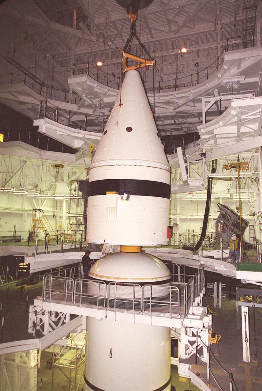
Inside the Vehicle Assembly Building, an overhead crane lowers the forward section of a solid rocket booster (SRB) toward the rest of the stack for mating. The forward section of each booster, from nose cap to forward skirt contains avionics, a sequencer, forward separation motors, a nose cone separation system, drogue and main parachutes, a recovery beacon, a recovery light, a parachute camera on selected flights and a range safety system. Each SRB weighs approximately 1.3 million pounds at launch. The SRB is part of the stack for Space Shuttle Discovery and the STS-92 mission, scheduled for launch Oct. 5, from Launch Pad 39A, on the fifth flight to the International Space Station

Inside the Vehicle Assembly Building, an overhead crane lowers the forward section of a solid rocket booster (SRB) toward the rest of the stack for mating. The forward section of each booster, from nose cap to forward skirt contains avionics, a sequencer, forward separation motors, a nose cone separation system, drogue and main parachutes, a recovery beacon, a recovery light, a parachute camera on selected flights and a range safety system. Each SRB weighs approximately 1.3 million pounds at launch. The SRB is part of the stack for Space Shuttle Discovery and the STS-92 mission, scheduled for launch Oct. 5, from Launch Pad 39A, on the fifth flight to the International Space Station

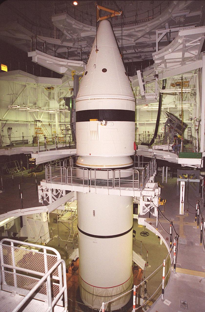
Inside the Vehicle Assembly Building, the forward section of a solid rocket booster (SRB) sits on top of the rest of the stack for mating. The forward section of each booster, from nose cap to forward skirt contains avionics, a sequencer, forward separation motors, a nose cone separation system, drogue and main parachutes, a recovery beacon, a recovery light, a parachute camera on selected flights and a range safety system. Each SRB weighs approximately 1.3 million pounds at launch. The SRB is part of the stack for Space Shuttle Discovery and the STS-92 mission, scheduled for launch Oct. 5, from Launch Pad 39A, on the fifth flight to the International Space Station
Inside the Vehicle Assembly Building, the forward section of a solid rocket booster (SRB) sits on top of the rest of the stack for mating. The forward section of each booster, from nose cap to forward skirt contains avionics, a sequencer, forward separation motors, a nose cone separation system, drogue and main parachutes, a recovery beacon, a recovery light, a parachute camera on selected flights and a range safety system. Each SRB weighs approximately 1.3 million pounds at launch. The SRB is part of the stack for Space Shuttle Discovery and the STS-92 mission, scheduled for launch Oct. 5, from Launch Pad 39A, on the fifth flight to the International Space Station

Inside the Vehicle Assembly Building, the forward section of a solid rocket booster (SRB) is lowered onto the rest of the stack for mating. The forward section of each booster, from nose cap to forward skirt contains avionics, a sequencer, forward separation motors, a nose cone separation system, drogue and main parachutes, a recovery beacon, a recovery light, a parachute camera on selected flights and a range safety system. Each SRB weighs approximately 1.3 million pounds at launch. The SRB is part of the stack for Space Shuttle Discovery and the STS-92 mission, scheduled for launch Oct. 5, from Launch Pad 39A, on the fifth flight to the International Space Station

Inside the Vehicle Assembly Building, an overhead crane centers the forward section of a solid rocket booster (SRB) above the rest of the stack it will be mated to. The forward section of each booster, from nose cap to forward skirt contains avionics, a sequencer, forward separation motors, a nose cone separation system, drogue and main parachutes, a recovery beacon, a recovery light, a parachute camera on selected flights and a range safety system. Each SRB weighs approximately 1.3 million pounds at launch. The SRB is part of the stack for Space Shuttle Discovery and the STS-92 mission, scheduled for launch Oct. 5, from Launch Pad 39A, on the fifth flight to the International Space Station
Inside the Vehicle Assembly Building, the forward section of a solid rocket booster (SRB) is lowered onto the rest of the stack for mating. The forward section of each booster, from nose cap to forward skirt contains avionics, a sequencer, forward separation motors, a nose cone separation system, drogue and main parachutes, a recovery beacon, a recovery light, a parachute camera on selected flights and a range safety system. Each SRB weighs approximately 1.3 million pounds at launch. The SRB is part of the stack for Space Shuttle Discovery and the STS-92 mission, scheduled for launch Oct. 5, from Launch Pad 39A, on the fifth flight to the International Space Station

Protective aerodynamic panels separate from the launch abort system following the liftoff of the Artemis II test flight on Wednesday, April 1, 2026, from Launch Complex 39B at NASA’s Kennedy Space Center in Florida. In the event of early ascent emergencies, the launch abort system would quickly pull the Orion spacecraft and the crew safely away from the SLS (Space Launch System) rocket. If needed for an abort, the launch abort system can accelerate from 0 to 500 mph in 2 seconds.
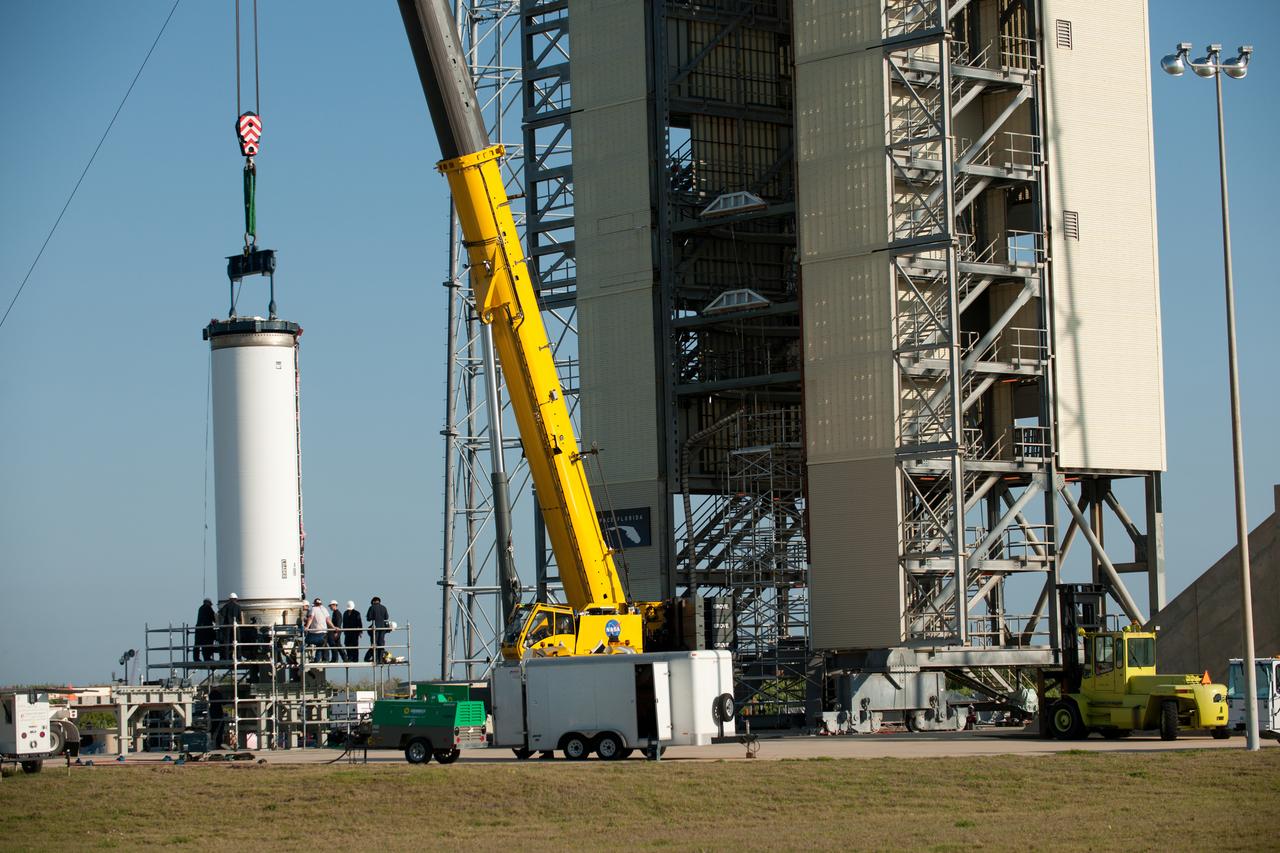
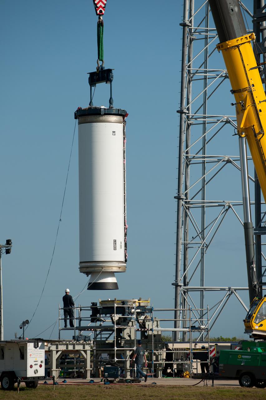
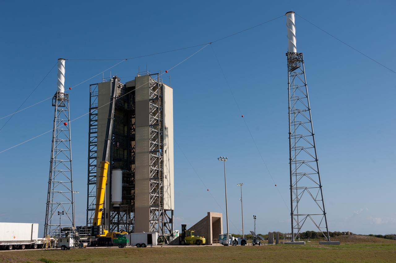
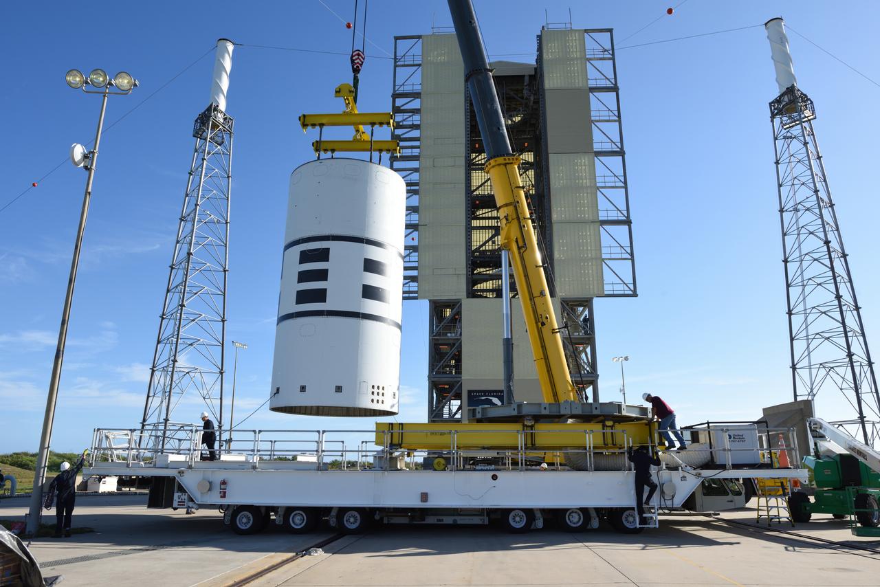
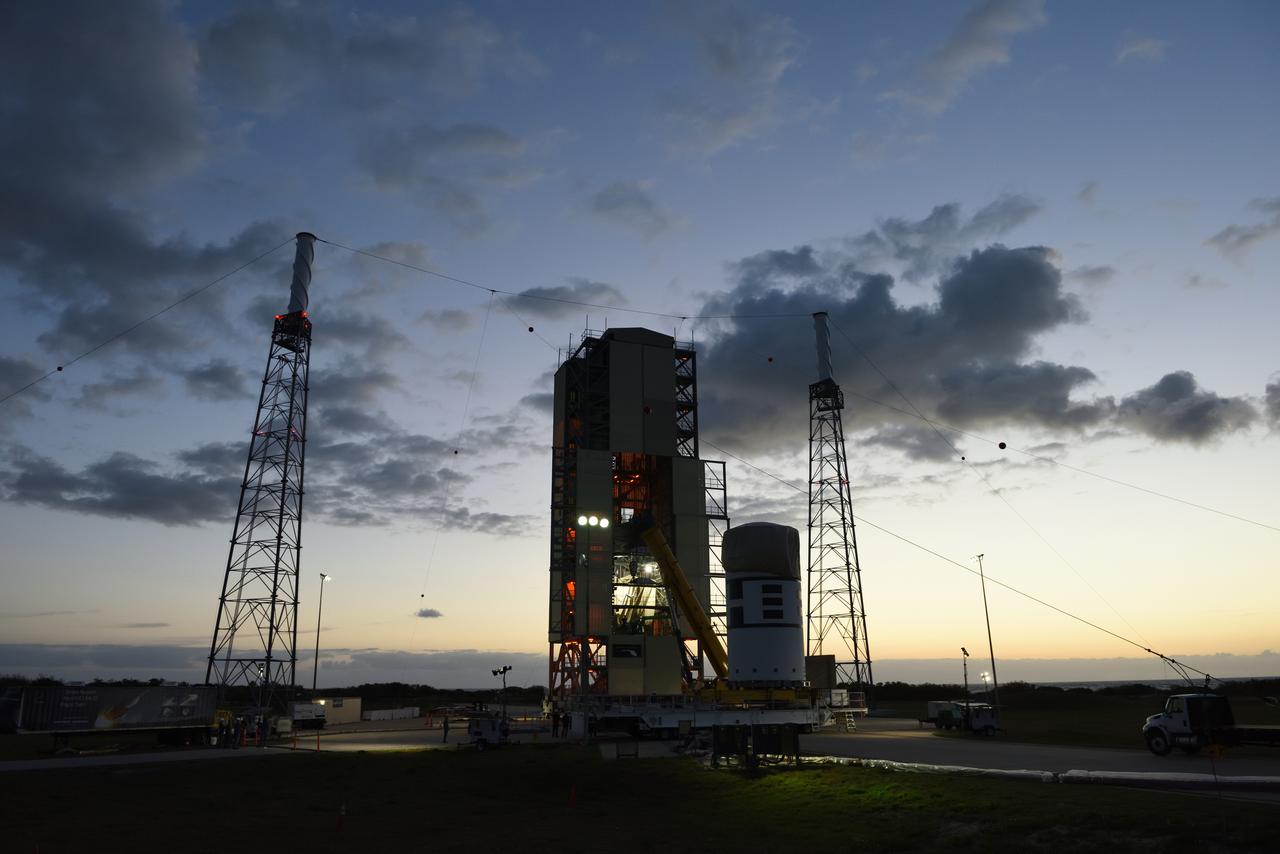
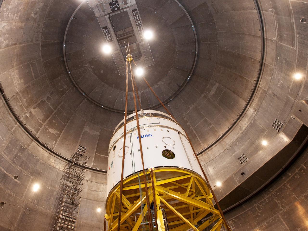
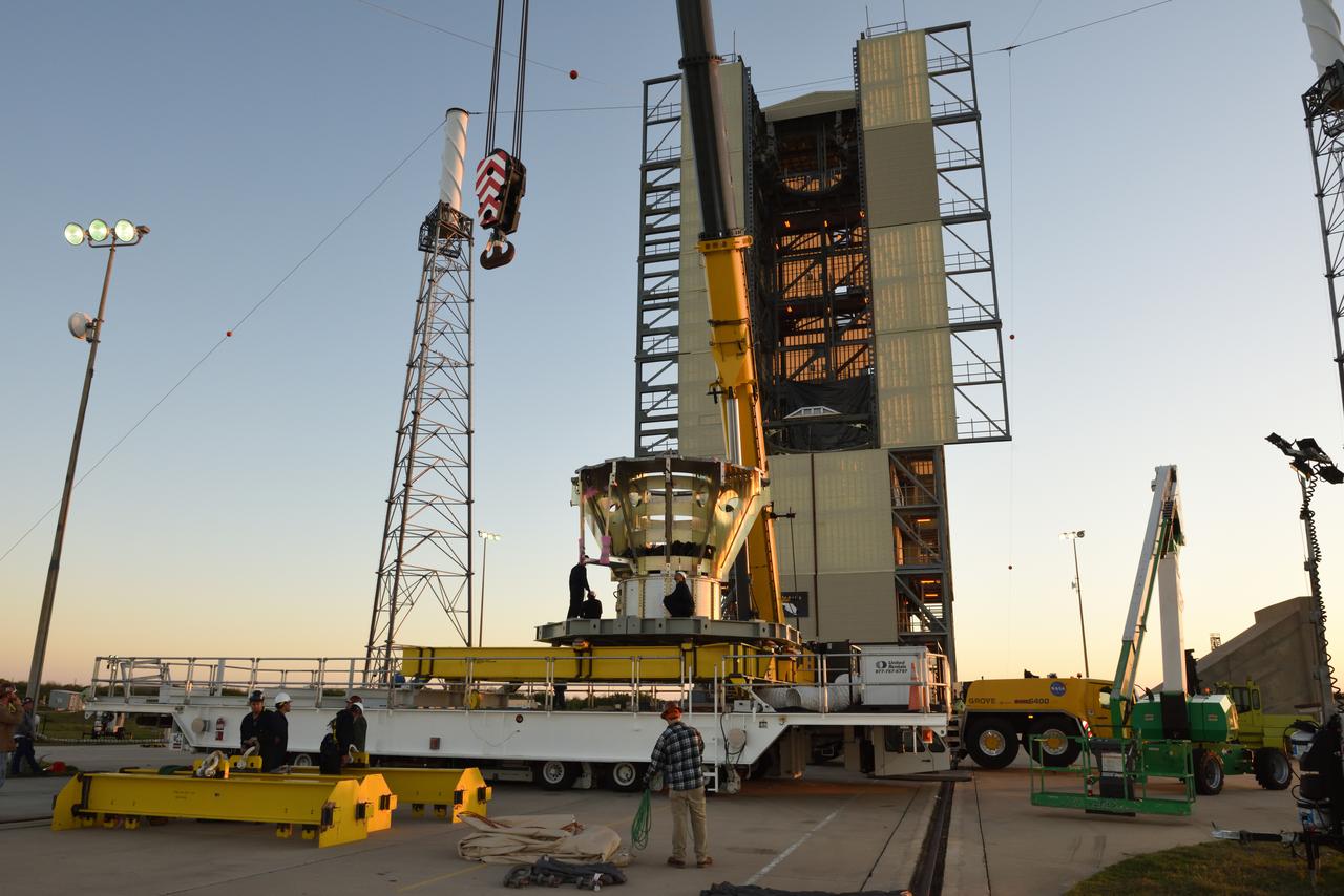
The Abort Test Booster, the rocket which will propel Orion's Launch Abort System and crew module / separation ring during the Ascent Abort -2 (AA-2) flight test, is stacked at the launch pad at Cape Canaveral Air Force Station in Florida on April 12, 2019.
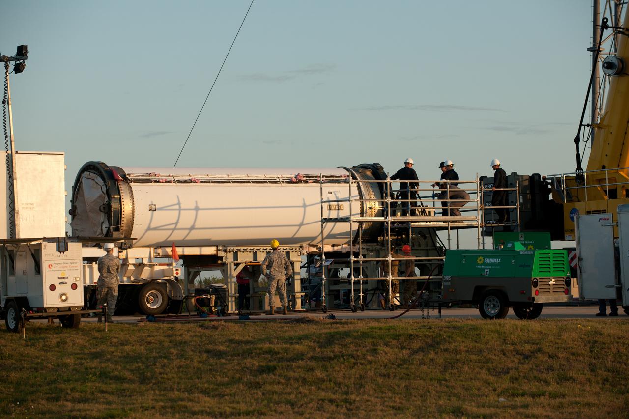
The Abort Test Booster, the rocket which will propel Orion's Launch Abort System and crew module / separation ring during the Ascent Abort -2 (AA-2) flight test, is stacked at the launch pad at Cape Canaveral Air Force Station in Florida on April 12, 2019.
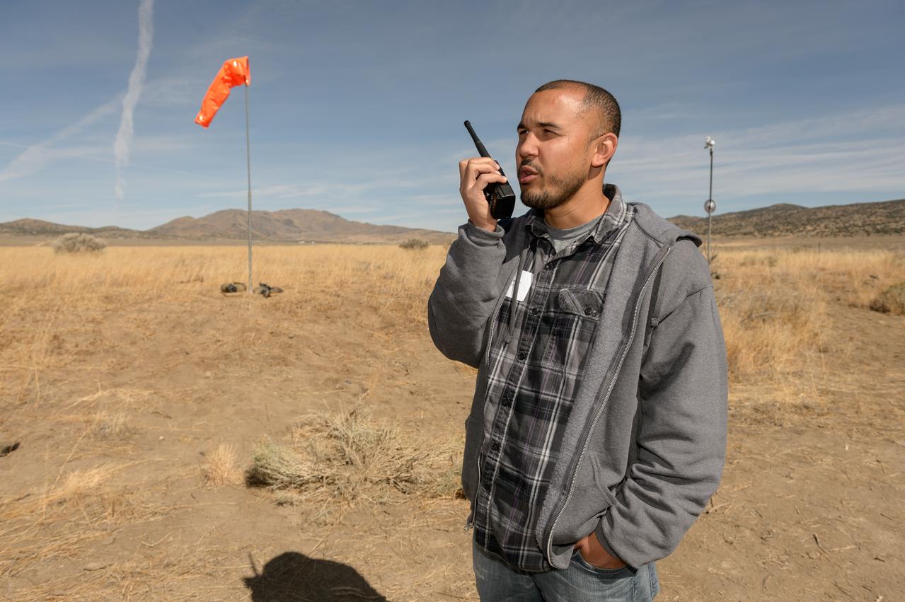
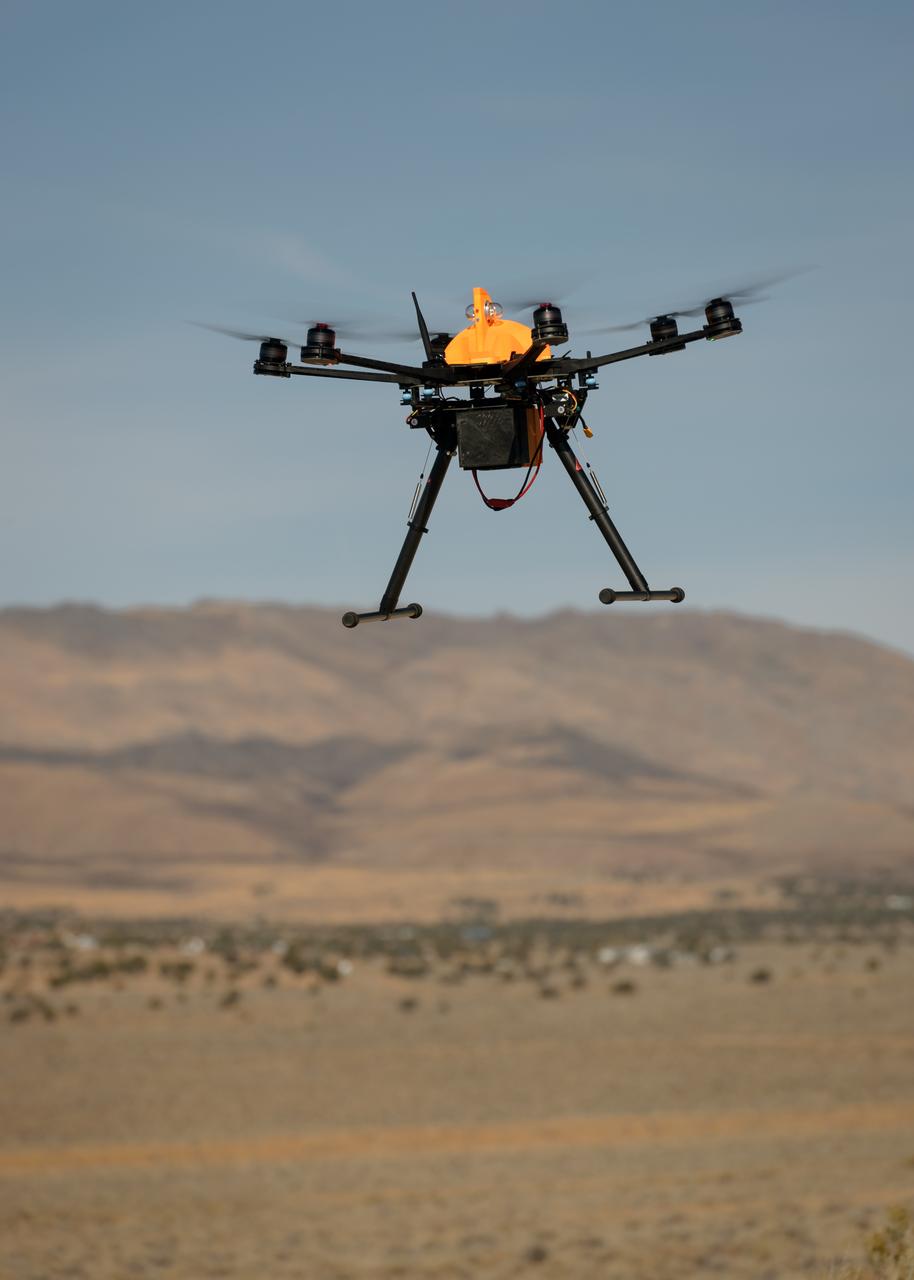
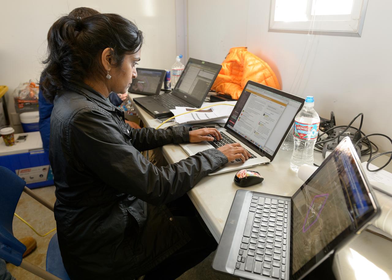
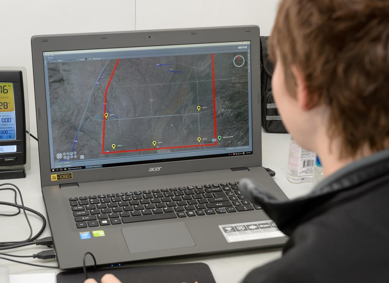
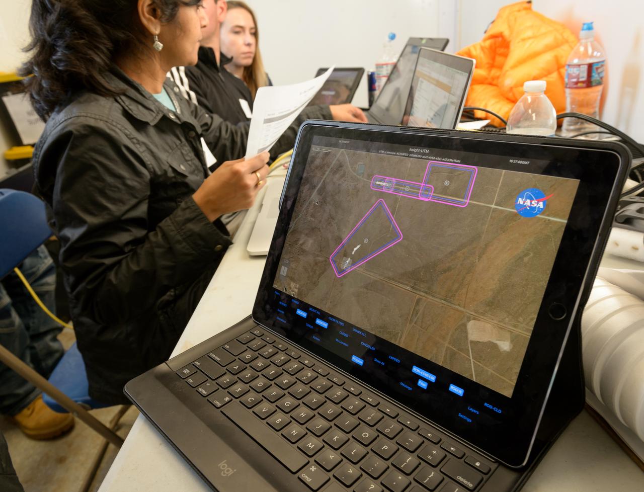
Test of Unmanned Aircraft Systems Traffic Management (UTM) technical capability Level 2 (TCL2) at Reno-Stead Airport, Nevada. During the test, five drones simultaneously crossed paths, separated by altitude. Two drones flew beyond visual line-of-sight and three flew within line-of-sight of their operators.
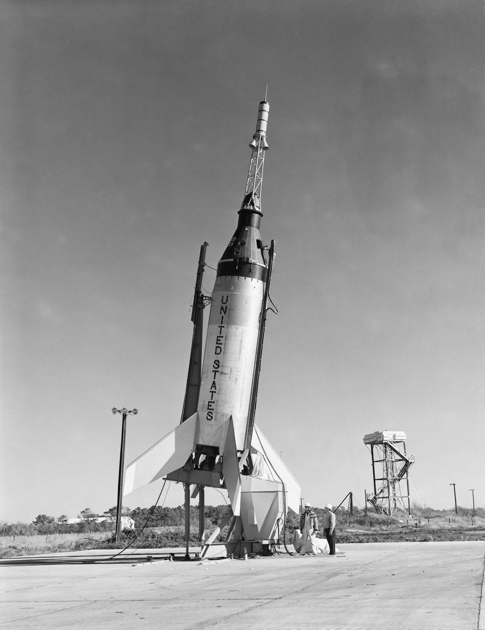
G60-02552 (8 Nov. 1960) --- Little Joe-5 prelaunch fittings shot before flight from Wallops Island. The suborbital test flight was to qualify the capsule system. The capsule did not separate from the booster. Photo credit: NASA
The Abort Test Booster, the rocket which will propel Orion's Launch Abort System and crew module / separation ring during the Ascent Abort -2 (AA-2) flight test, is stacked at the launch pad at Cape Canaveral Air Force Station in Florida on April 12, 2019.
The Abort Test Booster, the rocket which will propel Orion's Launch Abort System and crew module / separation ring during the Ascent Abort -2 (AA-2) flight test, is stacked at the launch pad at Cape Canaveral Air Force Station in Florida on April 12, 2019.
Test of Unmanned Aircraft Systems Traffic Management (UTM) technical capability Level 2 (TCL2) at Reno-Stead Airport, Nevada. During the test, five drones simultaneously crossed paths, separated by altitude. Two drones flew beyond visual line-of-sight and three flew within line-of-sight of their operators.
Test of Unmanned Aircraft Systems Traffic Management (UTM) technical capability Level 2 (TCL2) at Reno-Stead Airport, Nevada. During the test, five drones simultaneously crossed paths, separated by altitude. Two drones flew beyond visual line-of-sight and three flew within line-of-sight of their operators.
The Abort Test Booster, the rocket which will propel Orion's Launch Abort System and crew module / separation ring during the Ascent Abort -2 (AA-2) flight test, is stacked at the launch pad at Cape Canaveral Air Force Station in Florida on April 12, 2019.
The Abort Test Booster, the rocket which will propel Orion's Launch Abort System and crew module / separation ring during the Ascent Abort -2 (AA-2) flight test, is stacked at the launch pad at Cape Canaveral Air Force Station in Florida on April 12, 2019.
The Abort Test Booster, the rocket which will propel Orion's Launch Abort System and crew module / separation ring during the Ascent Abort -2 (AA-2) flight test, is stacked at the launch pad at Cape Canaveral Air Force Station in Florida on April 12, 2019.
The Abort Test Booster, the rocket which will propel Orion's Launch Abort System and crew module / separation ring during the Ascent Abort -2 (AA-2) flight test, is stacked at the launch pad at Cape Canaveral Air Force Station in Florida on April 12, 2019.
The Abort Test Booster, the rocket which will propel Orion's Launch Abort System and crew module / separation ring during the Ascent Abort -2 (AA-2) flight test, is stacked at the launch pad at Cape Canaveral Air Force Station in Florida on April 12, 2019.
The Abort Test Booster, the rocket which will propel Orion's Launch Abort System and crew module / separation ring during the Ascent Abort -2 (AA-2) flight test, is stacked at the launch pad at Cape Canaveral Air Force Station in Florida on April 12, 2019.
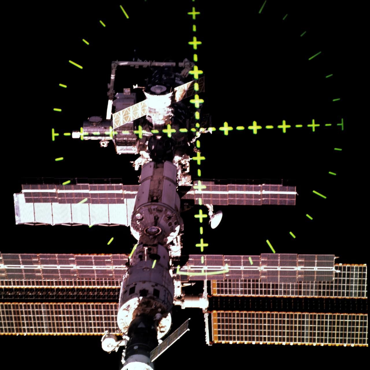
STS105-707-055 (20 August 2001) --- This view of the International Space Station (ISS) was captured with a 70mm handheld camera through the Space Shuttle Discovery's crew optical alignment system (COAS) during separation operations. The undocking took place at 9:52 a.m. (CDT), August 20, 2001.
Test of Unmanned Aircraft Systems Traffic Management (UTM) technical capability Level 2 (TCL2) at Reno-Stead Airport, Nevada. During the test, five drones simultaneously crossed paths, separated by altitude. Two drones flew beyond visual line-of-sight and three flew within line-of-sight of their operators.
The Abort Test Booster, the rocket which will propel Orion's Launch Abort System and crew module / separation ring during the Ascent Abort -2 (AA-2) flight test, is stacked at the launch pad at Cape Canaveral Air Force Station in Florida on April 12, 2019.
The Abort Test Booster, the rocket which will propel Orion's Launch Abort System and crew module / separation ring during the Ascent Abort -2 (AA-2) flight test, is stacked at the launch pad at Cape Canaveral Air Force Station in Florida on April 12, 2019.

Test of Unmanned Aircraft Systems Traffic Management (UTM) technical capability Level 2 (TCL2) at Reno-Stead Airport, Nevada. During the test, five drones simultaneously crossed paths, separated by altitude. Two drones flew beyond visual line-of-sight and three flew within line-of-sight of their operators.

Test of Unmanned Aircraft Systems Traffic Management (UTM) technical capability Level 2 (TCL2) at Reno-Stead Airport, Nevada. During the test, five drones simultaneously crossed paths, separated by altitude. Two drones flew beyond visual line-of-sight and three flew within line-of-sight of their operators.
Test of Unmanned Aircraft Systems Traffic Management (UTM) technical capability Level 2 (TCL2) at Reno-Stead Airport, Nevada. During the test, five drones simultaneously crossed paths, separated by altitude. Two drones flew beyond visual line-of-sight and three flew within line-of-sight of their operators.
The Abort Test Booster, the rocket which will propel Orion's Launch Abort System and crew module / separation ring during the Ascent Abort -2 (AA-2) flight test, is stacked at the launch pad at Cape Canaveral Air Force Station in Florida on April 12, 2019.
The Abort Test Booster, the rocket which will propel Orion's Launch Abort System and crew module / separation ring during the Ascent Abort -2 (AA-2) flight test, is stacked at the launch pad at Cape Canaveral Air Force Station in Florida on April 12, 2019.
The Abort Test Booster, the rocket which will propel Orion's Launch Abort System and crew module / separation ring during the Ascent Abort -2 (AA-2) flight test, is stacked at the launch pad at Cape Canaveral Air Force Station in Florida on April 12, 2019.
NASA Glenn conducted a test on the Ariane 5 Payload Fairing at Plum Brook’s Space Power Facility (SPF). The test was to qualify a new horizontal pyrotechnic separation system, which blew the two fairing halves apart and away from the payload during flight.
The Abort Test Booster, the rocket which will propel Orion's Launch Abort System and crew module / separation ring during the Ascent Abort -2 (AA-2) flight test, is stacked at the launch pad at Cape Canaveral Air Force Station in Florida on April 12, 2019.
The Abort Test Booster, the rocket which will propel Orion's Launch Abort System and crew module / separation ring during the Ascent Abort -2 (AA-2) flight test, is stacked at the launch pad at Cape Canaveral Air Force Station in Florida on April 12, 2019.
The Abort Test Booster, the rocket which will propel Orion's Launch Abort System and crew module / separation ring during the Ascent Abort -2 (AA-2) flight test, is stacked at the launch pad at Cape Canaveral Air Force Station in Florida on April 12, 2019.
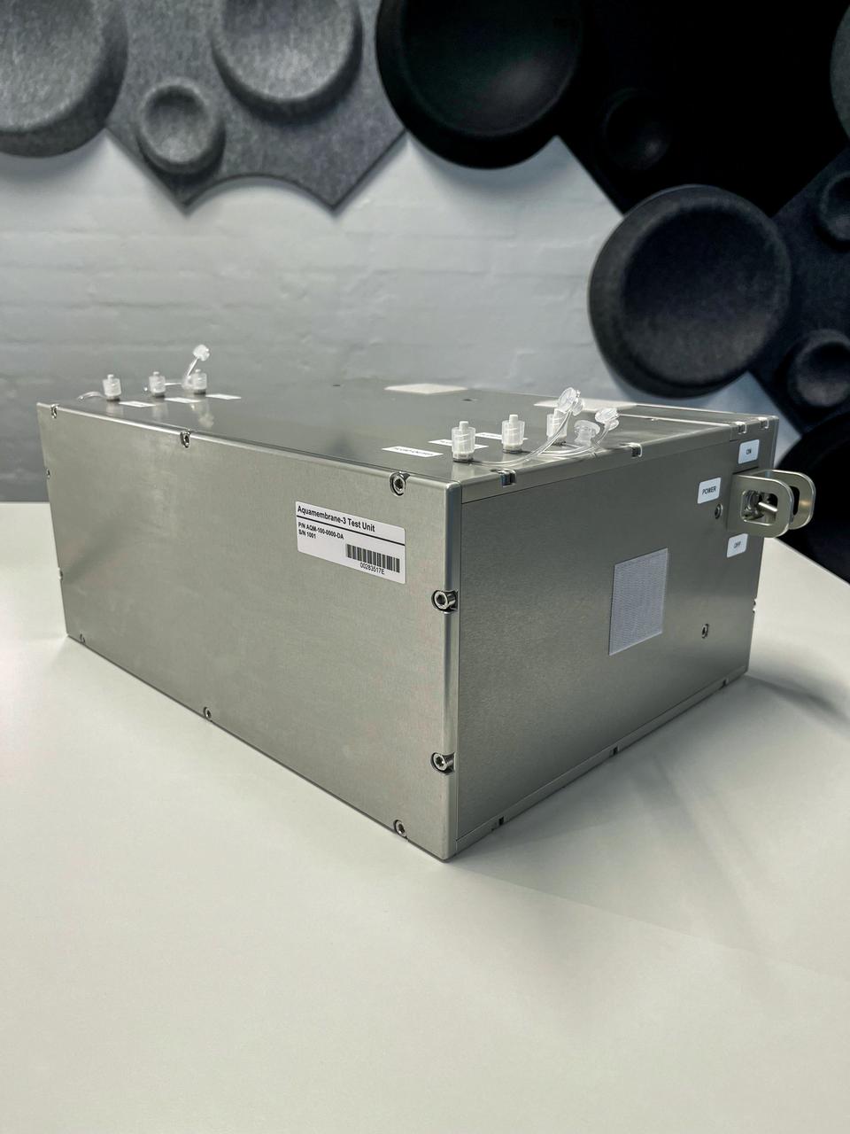
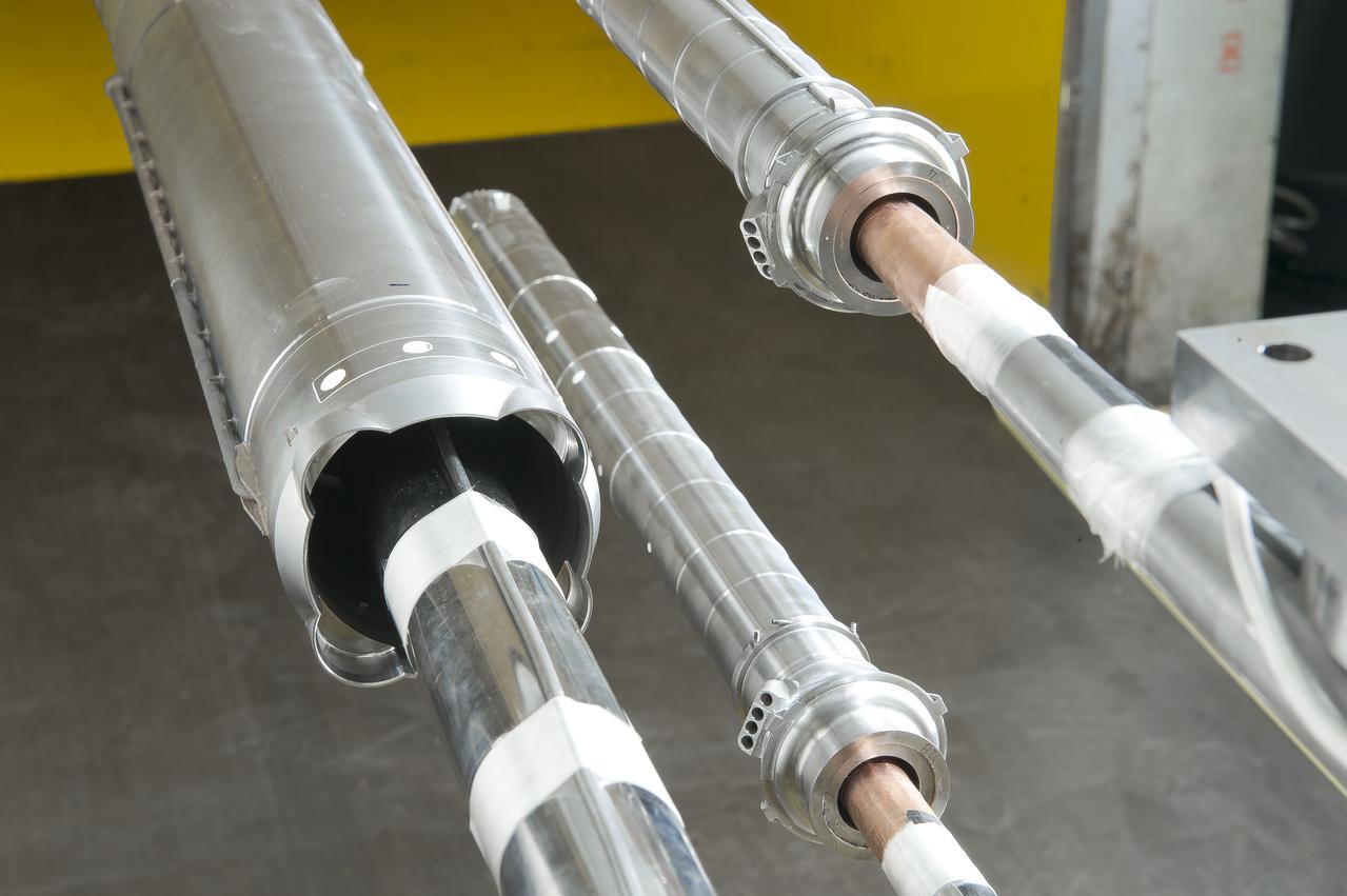
jsc2023e055873 (10/5/2023) --- The Testing Contaminant Rejection of Aquaporin Inside® HFFO Module (Aquamembrane-3) hardware consists of three separate and parallel systems to quantify the membrane's water flux and contamination rejection in microgravity, which are key parameters for a full water recovery system. This image shows the unit containing the forward osmosis membranes and other fluid system components.
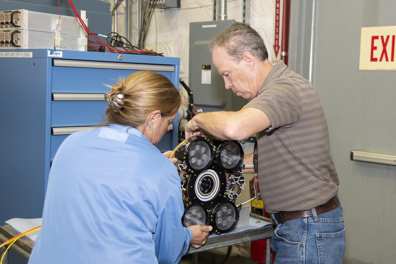
Dan Nolan, who with engineer Lucas Moxey developed the camera system shown in the photo, is seen working with April Torres to prepare it for vibration testing at NASA’s Armstrong Flight Research Center. The camera system is designed to operate as part of the Orion AA-2 test article’s abort test booster/separation ring developmental flight instrumentation subsystem. The testing proved the camera system could function and endure the predicted flight environment.
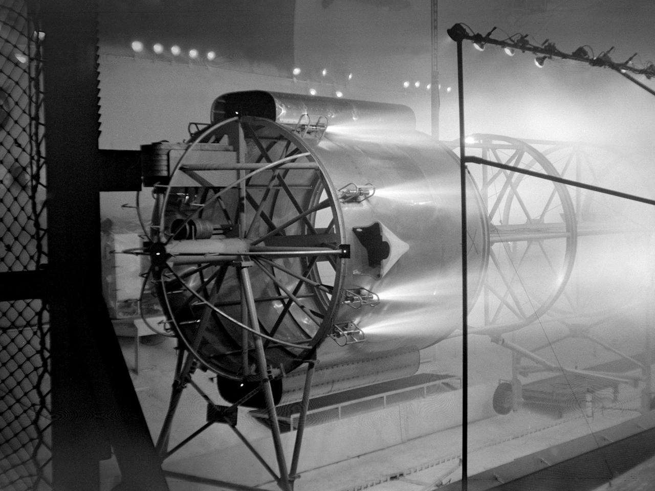
An Atlas/Centaur mass model undergoes a separation test inside the Space Power Chambers at NASA Lewis Research Center. Lewis was in the midst of an extensive effort to prepare the Centaur second-stage rocket for its missions to send the Surveyor spacecraft to the moon as a precursor to the Apollo missions. As part of these preparations, Lewis management decided to convert its Altitude Wind Tunnel into two large test chambers—the Space Power Chambers. The conversion included the removal of the tunnel’s internal components and the insertion of bulkheads to seal off the new chambers within the tunnel. One chamber could simulate conditions found at 100 miles altitude, while this larger chamber simulated the upper atmosphere. In this test series, researchers wanted to verify that the vehicle’s retrorockets would properly separate the Centaur from the Atlas. The model was suspended horizontally on a trolley system inside chamber. A net was hung at one end to catch the jettisoned Atlas model. The chamber atmosphere was reduced to a pressure altitude of 100,000 feet, and high-speed cameras were synchronized to the ignition of the retrorockets. The simulated Centaur is seen here jettisoning from the Atlas out of view to the right. The study resulted in a new jettison method that would significantly reduce the separation time and thus minimize the danger of collision between the two stages during separation.

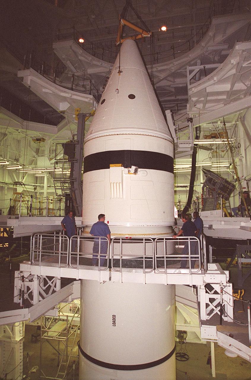
Workers in the Vehicle Assembly Building check the connections on the forward section of a solid rocket booster (SRB) being mated to the rest of the stack below it. The forward section of each booster, from nose cap to forward skirt contains avionics, a sequencer, forward separation motors, a nose cone separation system, drogue and main parachutes, a recovery beacon, a recovery light, a parachute camera on selected flights and a range safety system. Each SRB weighs approximately 1.3 million pounds at launch. The SRB is part of the stack for Space Shuttle Discovery and the STS-92 mission, scheduled for launch Oct. 5, from Launch Pad 39A, on the fifth flight to the International Space Station. Payloads on the mission include the Z-1 truss and Pressurized Mating Adapter-3, components of the Space Station
Workers in the Vehicle Assembly Building check the connections on the forward section of a solid rocket booster (SRB) being mated to the rest of the stack below it. The forward section of each booster, from nose cap to forward skirt contains avionics, a sequencer, forward separation motors, a nose cone separation system, drogue and main parachutes, a recovery beacon, a recovery light, a parachute camera on selected flights and a range safety system. Each SRB weighs approximately 1.3 million pounds at launch. The SRB is part of the stack for Space Shuttle Discovery and the STS-92 mission, scheduled for launch Oct. 5, from Launch Pad 39A, on the fifth flight to the International Space Station. Payloads on the mission include the Z-1 truss and Pressurized Mating Adapter-3, components of the Space Station
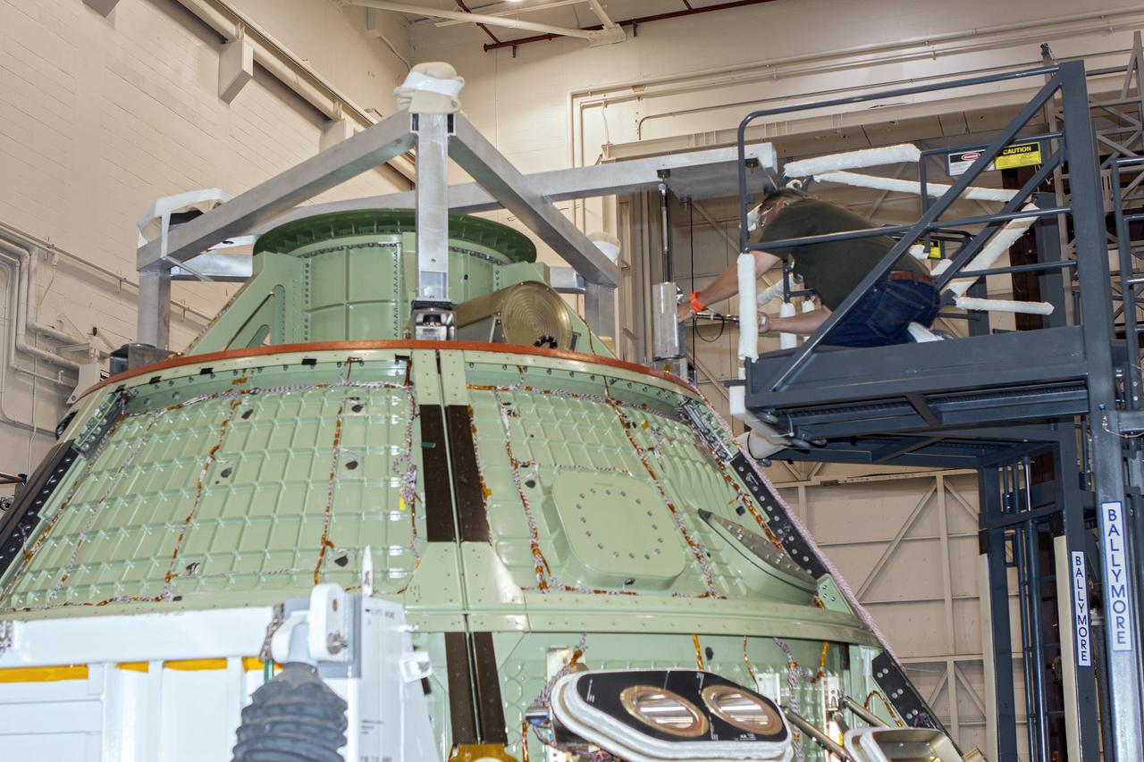
CAPE CANAVERAL, Fla. -- Inside the Launch Equipment Test Facility at NASA’s Kennedy Space in Florida, a second firing of the escape hold down post has occurred during a pyrotechnic bolt test on the Orion ground test vehicle. Lockheed Martin performed tests over a series of days on the explosive bolts that separate Orion from the launch abort system. Data was collected on the effect of shock waves on Orion during the explosive bolt separation. Orion is the exploration spacecraft designed to carry crews to space beyond low Earth orbit. It will provide emergency abort capability, sustain the crew during the space travel and provide safe re-entry from deep space return velocities. The first unpiloted test flight of the Orion is scheduled to launch in 2014 atop a Delta IV rocket and in 2017 on a Space Launch System rocket. For more information, visit http://www.nasa.gov/orion. Photo credit: NASA/Jim Grossmann
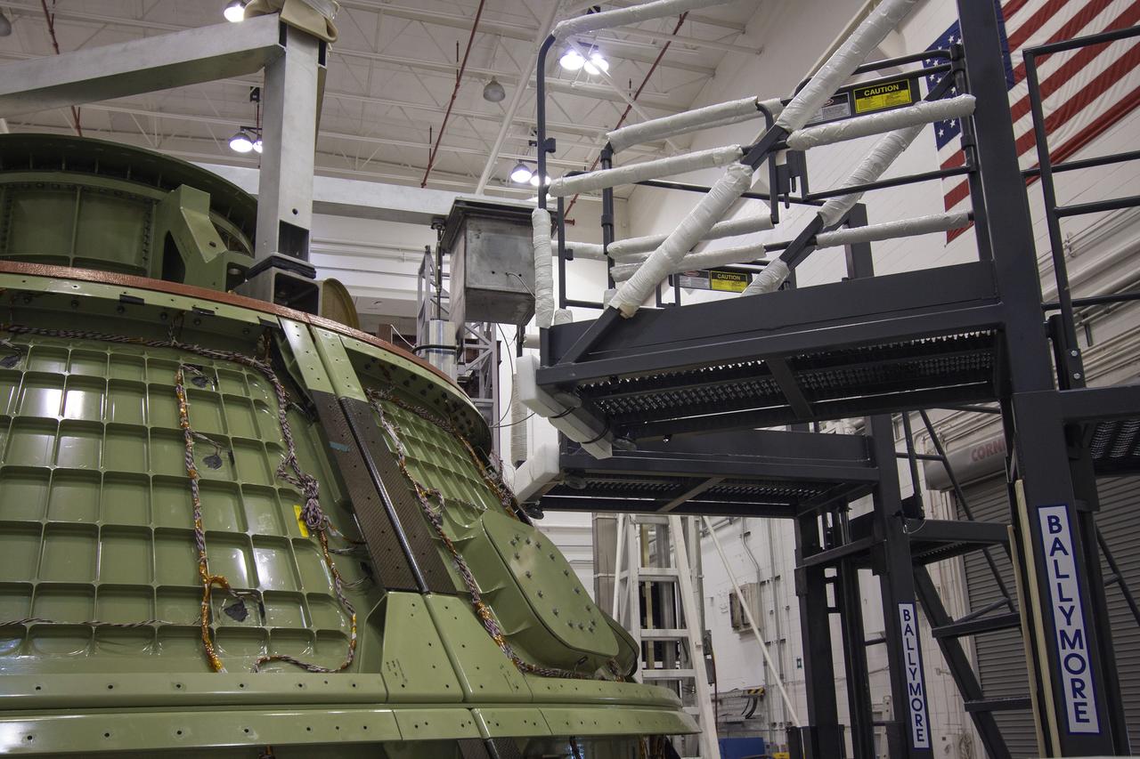
CAPE CANAVERAL, Fla. -- The Orion ground test vehicle sits on a test stand in the Launch Equipment Test Facility at NASA’s Kennedy Space Center in Florida while engineers and technicians prepare it for a pyrotechnic bolt test. Lockheed Martin performed tests over a series of days on the explosive bolts that separate Orion from the launch abort system. Data was collected on the effect of shock waves on Orion during the explosive bolt separation. Orion is the exploration spacecraft designed to carry crews to space beyond low Earth orbit. It will provide emergency abort capability, sustain the crew during the space travel and provide safe re-entry from deep space return velocities. The first unpiloted test flight of the Orion is scheduled to launch in 2014 atop a Delta IV rocket and in 2017 on a Space Launch System rocket. For more information, visit http://www.nasa.gov/orion. Photo credit: NASA/Jim Grossmann
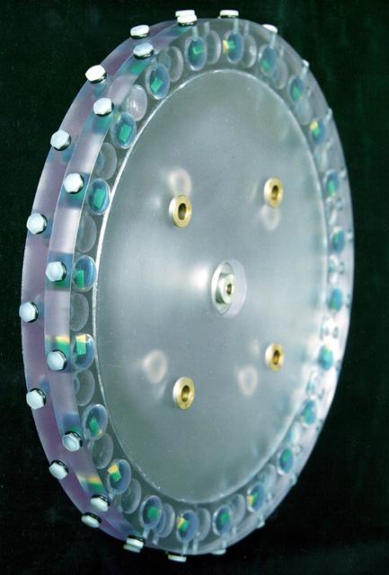
VANDENBERG AIR FORCE BASE, Calif. – At Vandenberg Air Force Base in California, technicians and engineers prepare a separation system ring that will be attached to NASA's Interface Region Imaging Spectrograph, or IRIS, spacecraft. The separation system will push IRIS away from an Orbital Pegasus XL rocket when the spacecraft reaches its proper orbit after launch. Scheduled for launch from Vandenberg Air Force Base no earlier than June 26, 2013, IRIS will open a new window of discovery by tracing the flow of energy and plasma through the chromospheres and transition region into the sun’s corona using spectrometry and imaging. IRIS fills a crucial gap in our ability to advance studies of the sun-to-Earth connection by tracing the flow of energy and plasma through the foundation of the corona and the region around the sun known as the heliosphere. For more information, visit http:__iris.gsfc.nasa.gov Photo credit: NASA_Randy Beaudoin
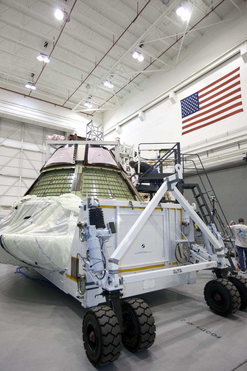
CAPE KENNEDY, Fla. -- The Orion ground test vehicle sits on a test stand in the Launch Equipment Test Facility at NASA’s Kennedy Space Center in Florida while engineers and technicians prepare it for a pyrotechnic bolt test. Lockheed Martin performed tests over a series of days on the explosive bolts that separate Orion from the launch abort system. Data was collected on the effect of shock waves on Orion during the explosive bolt separation. Orion is the exploration spacecraft designed to carry crews to space beyond low Earth orbit. It will provide emergency abort capability, sustain the crew during the space travel and provide safe re-entry from deep space return velocities. The first unpiloted test flight of the Orion is scheduled to launch in 2014 atop a Delta IV rocket and in 2017 on a Space Launch System rocket. For more information, visit http://www.nasa.gov/orion. Photo credit: NASA/Kim Shiflett