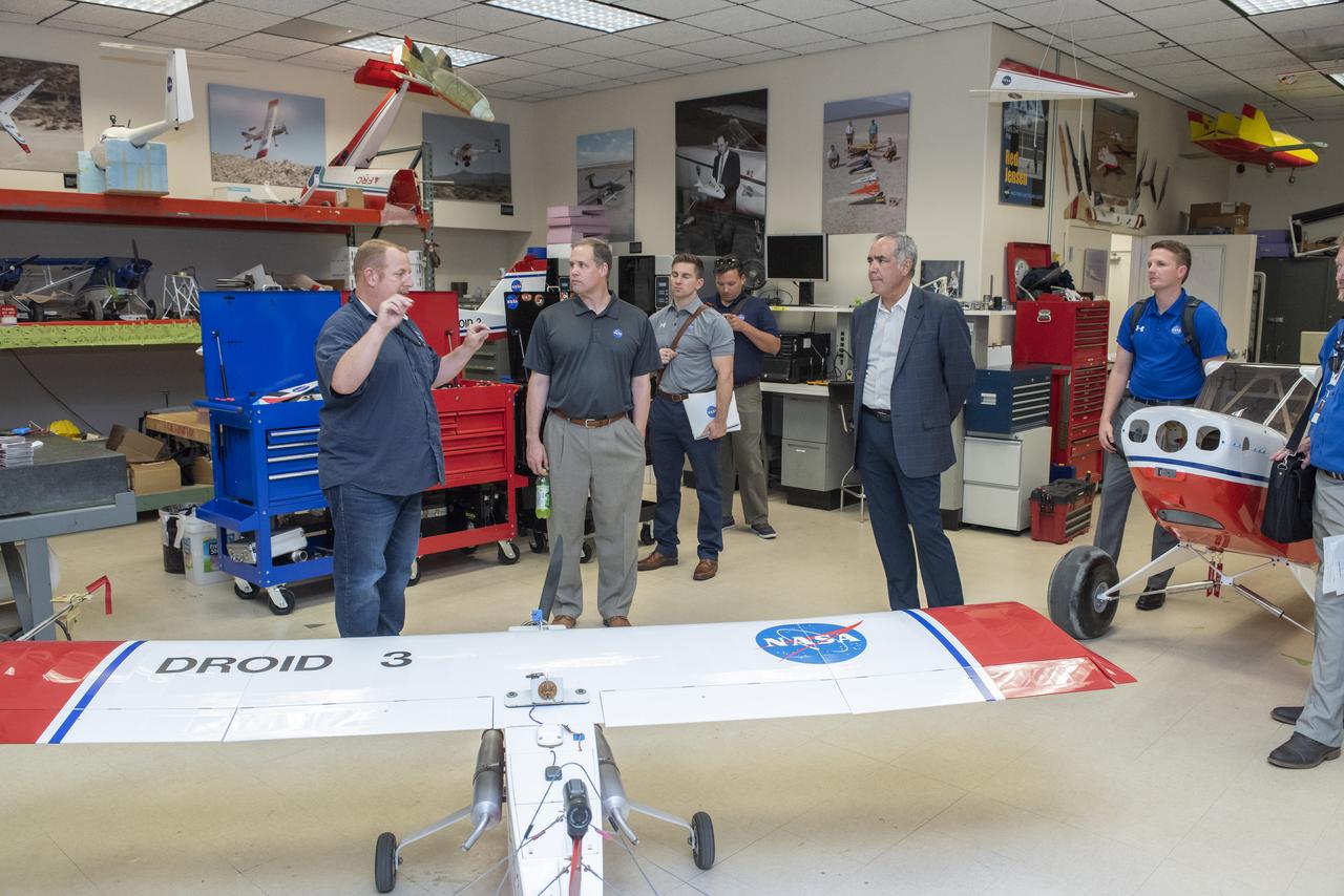
Armstrong's Robert "Red" Jensen talks to Bridenstine about using small scale aircraft to test aeronautical concepts keeping cost of aviation discoveries lower until technology is proved for larger aircraft.
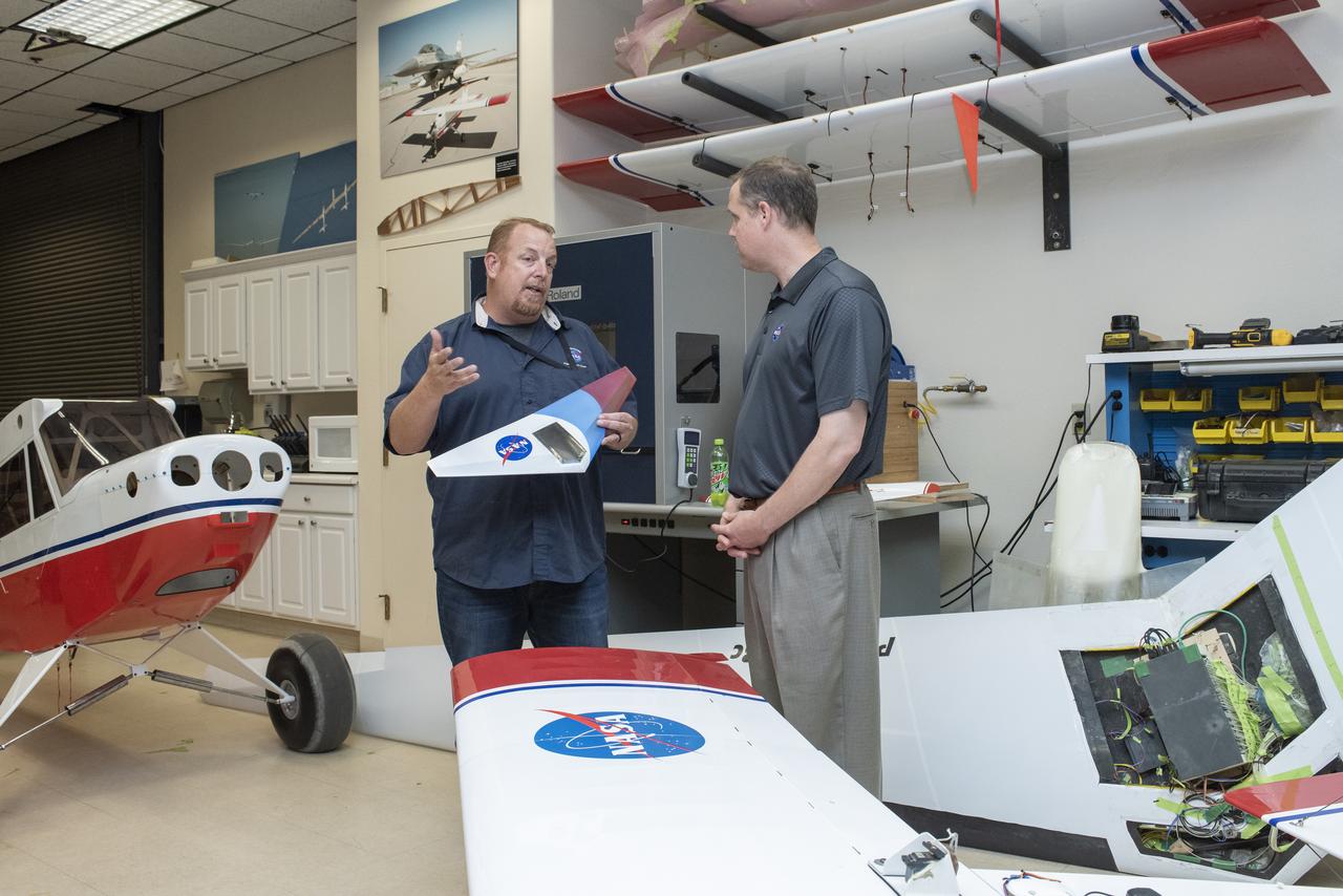
Armstrong's Robert "Red" Jensen talks to Bridenstine about using small scale aircraft to test aeronautical concepts keeping cost of aviation discoveries lower until technology is proved for larger aircraft.
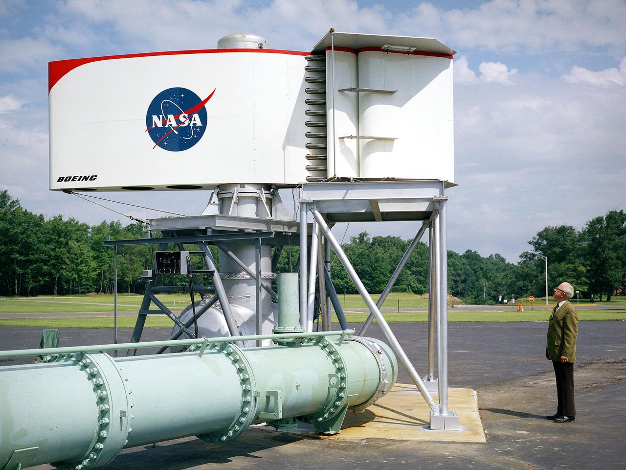
The augmentor wing concept was introduced during the early 1960s to enhance the performance of vertical and short takeoff (VSTOL) aircraft. The leading edge of the wing has full-span vertical flaps, and the trailing edge has double-slotted flaps. This provides aircraft with more control in takeoff and landing conditions. The augmentor wing also produced lower noise levels than other VSTOL designs. In the early 1970s Boeing Corporation built a Buffalo C-8A augmentor wing research aircraft for Ames Research Center. Researches at Lewis Research Center concentrated their efforts on reducing the noise levels of the wing. They initially used small-scale models to develop optimal nozzle screening methods. They then examined the nozzle designs on a large-scale model, seen here on an external test stand. This test stand included an airflow system, nozzle, the augmentor wing, and a muffler system below to reduce the atmospheric noise levels. The augmentor was lined with noise-reducing acoustic panels. The Lewis researchers were able to adjust the airflow to simulate conditions at takeoff and landing. Once the conditions were stabilized they took noise measurements from microphones placed in all directions from the wing, including an aircraft flying over. They found that the results coincided with the earlier small-scale studies for landing situations but not takeoffs. The acoustic panels were found to be successful.

Tour of the Electrified Powertrain Flight Demonstration in the HyPER lab on June 17th, 2024 at Glenn Research Center. NASA’s Electrified Powertrain Flight Demonstration (EPFD) project focuses advancing the future of sustainable aviation by turning hybrid electric flight into a reality. HyPER is a hardware-in-the-loop laboratory that was designed specifically to investigate the dynamic interactions between turbomachinery, the electric power system, and the constantly varying loads of electrified aircraft. It is a small-scale lab capable of rapid reconfiguration through software. This allows the emulation of new engines using simulation models that are easily replaced and then appropriately scaled for power and inertia to the test hardware. Photo Credit: (NASA/Sara Lowthian-Hanna)
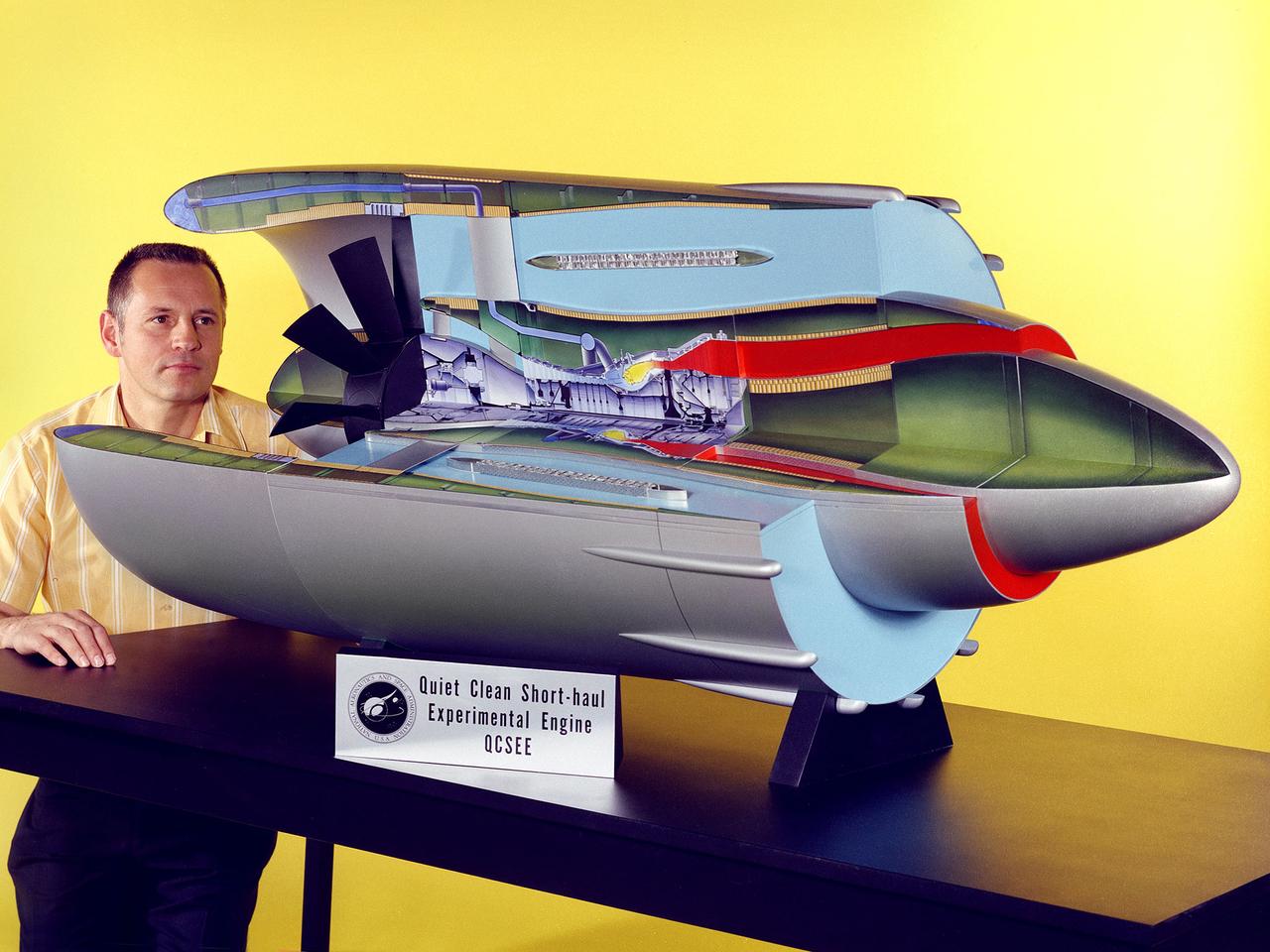
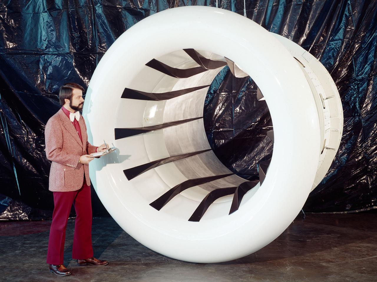
Program manager Carl Ciepluch poses with a model of the Quiet Clean Short Haul Experimental Engine (QCSEE) conceived by the National Aeronautics and Space Administration (NASA) Lewis Research Center. The QCSEE engine was designed to power future short-distance transport aircraft without generating significant levels of noise or pollution and without hindering performance. The engines were designed to be utilized on aircraft operating from small airports with short runways. Lewis researchers investigated two powered-lift designs and an array of new technologies to deal with the shorter runways. Lewis contracted General Electric to design the two QCSEE engines—one with over-the-wing power-lift and one with an under-the-wing design. A scale model of the over-the-wing engine was tested in the Full Scale Tunnel at the Langley Research Center in 1975 and 1976. Lewis researchers investigated both versions in a specially-designed test stand, the Engine Noise Test Facility, on the hangar apron. The QCSEE engines met the goals set out by the NASA researchers. The aircraft industry, however, never built the short-distance transport aircraft for which the engines were intended. Different technological elements of the engine, however, were applied to some future General Electric engines.
Brent Miller, of the V/STOL and Noise Division at the National Aeronautics and Space Administration (NASA) Lewis Research Center, poses with a sonic inlet for the NASA Quiet Engine Program. NASA Lewis had first investigated methods for reducing aircraft engine noise in the mid-1950s. Those efforts were resurrected and expanded in the late 1960s. The researchers found that the use of a sonic, or high-throat-Mach-number, inlet was effective at reducing the noise from the engine inlet. The device accelerated the inlet air to near-sonic speeds which kept the forward moving sound waves away from the inlet. The device also deflected the sound waves into the wall to further reduce the noise. NASA Lewis researchers tested models of the sonic inlet in their 9- by 15-Foot Low Speed Wind Tunnel. They found that the general level of aerodynamic performance was good. The tests during simulated takeoff and landing conditions demonstrated the sonic inlet’s ability to provide good aerodynamic and acoustic performance The researchers then successfully tested two full-scale sonic inlet designs, one from Pratt and Whitney and one from General Electric, with fans. A full-scale engine was installed on a thrust stand to determine the sonic inlet’s effect on the engine’s performance. The amount of noise reduction increased as the inlet flow velocity increased, but the full-scale tests did not produce as great a decrease in noise as the earlier small-scale tests.
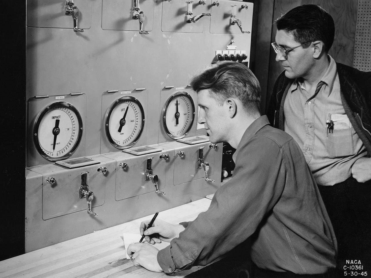
Researchers at the National Advisory Committee for Aeronautics (NACA) Aircraft Engine Research Laboratory monitor a ramjet's performance in the Altitude Wind Tunnel from the control room. The soundproof control room was just a few feet from the tunnel’s 20-foot-diameter test section. In the control room, the operators could control all aspects of the tunnel’s operation, including the air density, temperature, and speed. They also operated the engine or test article in the test section by controlling the angle-of-attack, speed, power, and other parameters. The men in this photograph are monitoring the engine’s thrust and lift. A NACA-designed 20-inch-diameter ramjet was installed in the tunnel in May 1945. Thrust figures from these runs were compared with drag data from tests of scale models in small supersonic tunnels to verify the ramjet’s feasibility. The tunnel was used to analyze the ramjet’s overall performance up to altitudes of 47,000 feet and speeds to Mach 1.84. The researchers found that an increase in altitude caused a reduction in the engine’s horsepower and identified optimal flameholder configurations.
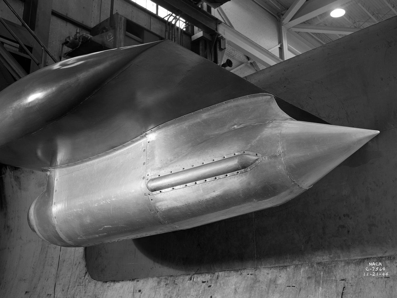
The Westinghouse 19XB turbojet seen from the side in the Altitude Wind Tunnel (AWT) test section at the National Advisory Committee for Aeronautics (NACA) Aircraft Engine Research Laboratory. Westinghouse started the development of a series of relatively small axial-flow turbojets for the Navy shortly after Pearl Harbor. In 1943 the 19A engine became both the first operational US-designed jet engine and the only U.S. turbojet incorporated into an aircraft during the war in Europe. In March 1943 Westinghouse agreed to create an improved six-stage 1400-pound thrust version, the 19B. The engine underwent its first test run a year later in March 1944. Almost immediately the navy agreed to Westinghouse’s proposal for the even larger 10-stage, 1600-pound-thrust 19XB prototype. By July 1944 the navy had contracted with the NACA for the testing of both engines in the AWT. The tunnel was the nation’s only facility for studying full-scale engines in simulated altitude conditions. The wind tunnel investigations, which began on September 9, 1944, revealed the superiority of the previously untested 19XB over the 19B. The 19B engines failed to restart consistently and suffered combustion blowouts above 17,000 feet. The 19XB, however, performed well and restarted routinely at twice that altitude. Two months later on January 26, 1945, two 19Bs powered a McDonnell XFD–1 Phantom, the US Navy’s first fighter jet, on its initial flight. Following its exceptional performance in the AWT, the 19XB engines soon replaced the 19Bs in the Phantom.
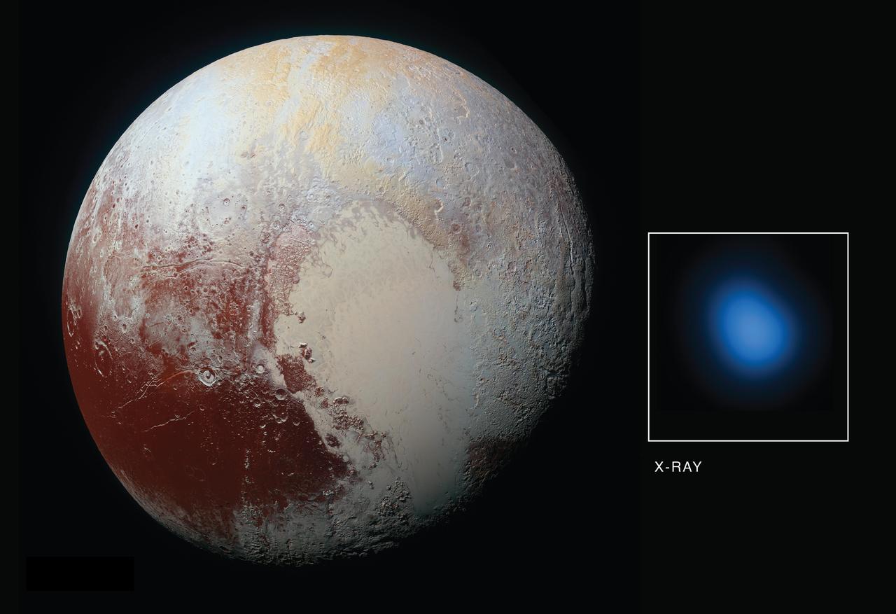
The first detection of Pluto in X-rays has been made using NASA's Chandra X-ray Observatory in conjunction with observations from NASA's New Horizons spacecraft. As New Horizons approached Pluto in late 2014 and then flew by the planet during the summer of 2015, Chandra obtained data during four separate observations. During each observation, Chandra detected low-energy X-rays from the small planet. The main panel in this graphic is an optical image taken from New Horizons on its approach to Pluto, while the inset shows an image of Pluto in X-rays from Chandra. There is a significant difference in scale between the optical and X-ray images. New Horizons made a close flyby of Pluto but Chandra is located near the Earth, so the level of detail visible in the two images is very different. The Chandra image is 180,000 miles across at the distance of Pluto, but the planet is only 1,500 miles across. Pluto is detected in the X-ray image as a point source, showing the sharpest level of detail available for Chandra or any other X-ray observatory. This means that details over scales that are smaller than the X-ray source cannot be seen here. Detecting X-rays from Pluto is a somewhat surprising result given that Pluto - a cold, rocky world without a magnetic field - has no natural mechanism for emitting X-rays. However, scientists knew from previous observations of comets that the interaction between the gases surrounding such planetary bodies and the solar wind - the constant streams of charged particles from the sun that speed throughout the solar system -- can create X-rays. The researchers were particularly interested in learning more about the interaction between the gases in Pluto's atmosphere and the solar wind. The New Horizon spacecraft carries an instrument designed to measure that activity up-close -- Solar Wind Around Pluto (SWAP) -- and scientists examined that data and proposed that Pluto contains a very mild, close-in bowshock, where the solar wind first "meets" Pluto (similar to a shock wave that forms ahead of a supersonic aircraft) and a small wake or tail behind the planet. The immediate mystery is that Chandra's readings on the brightness of the X-rays are much higher than expected from the solar wind interacting with Pluto's atmosphere. The Chandra detection is also surprising since New Horizons discovered Pluto's atmosphere was much more stable than the rapidly escaping, "comet-like" atmosphere that many scientists expected before the spacecraft flew past in July 2015. In fact, New Horizons found that Pluto's interaction with the solar wind is much more like the interaction of the solar wind with Mars, than with a comet. While Pluto is releasing enough gas from its atmosphere to make the observed X-rays, there isn't enough solar wind flowing directly at Pluto at its great distance from the Sun to make them according to certain theoretical models. There are several suggested possibilities for the enhanced X-ray emission from Pluto. These include a much wider and longer tail of gases trailing Pluto than New Horizons detected using its SWAP instrument. Because Pluto is so small compared to the size of a Chandra point source, scientists may be unable to detect such a tail in X-rays. Other possibilities are that interplanetary magnetic fields are focusing more particles than expected from the solar wind into the region around Pluto, or the low density of the solar wind in the outer solar system at the distance of Pluto could allow for the formation of a doughnut, or torus, of neutral gas centered around Pluto's orbit. It will take deeper and higher resolution images of X-rays from Pluto's environment than we currently have from Chandra to distinguish between these possibilities. http://photojournal.jpl.nasa.gov/catalog/PIA21061
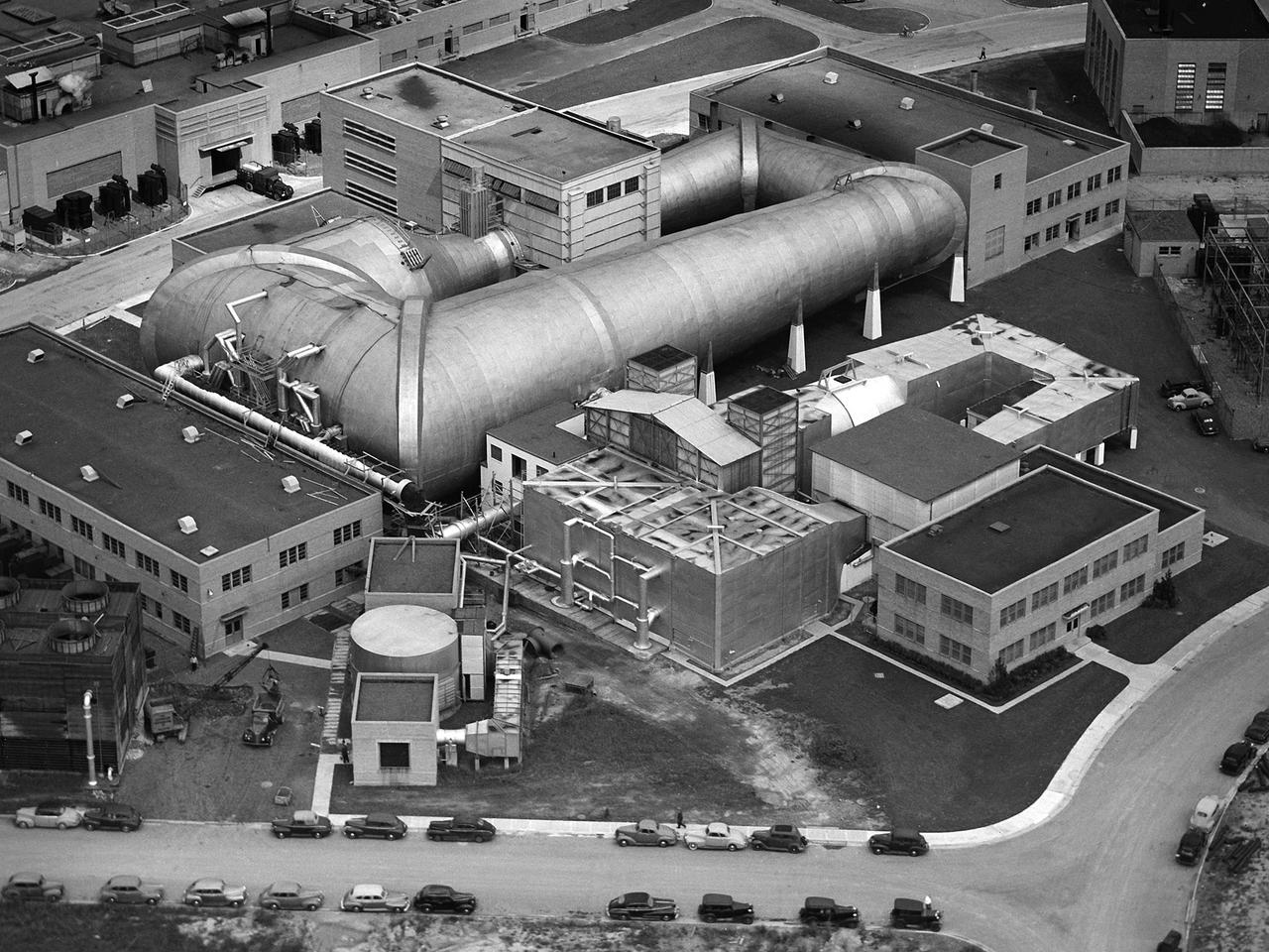
This aerial photograph shows the entire original wind tunnel complex at the National Advisory Committee for Aeronautics (NACA) Aircraft Engine Research Laboratory. The large Altitude Wind Tunnel (AWT) at the center of the photograph dominates the area. The Icing Research Tunnel to the right was incorporated into the lab’s design to take advantage of the AWT’s powerful infrastructure. The laboratory’s first supersonic wind tunnel was added to this complex just prior to this September 1945 photograph. The AWT was the nation’s only wind tunnel capable of studying full-scale engines in simulated flight conditions. The AWT’s test section and control room were within the two-story building near the top of the photograph. The exhauster equipment used to thin the airflow and the drive motor for the fan were in the building to the right of the tunnel. The unique refrigeration equipment was housed in the structure to the left of the tunnel. The Icing Research Tunnel was an atmospheric tunnel that used the AWT’s refrigeration equipment to simulate freezing rain inside its test section. A spray bar system inside the tunnel was originally used to create the droplets. The 18- by 18-inch supersonic wind tunnel was built in the summer of 1945 to take advantage of the AWT’s powerful exhaust system. It was the lab’s first supersonic tunnel and could reach Mach 1.91. Eventually the building would house three small supersonic tunnels, referred to as the “stack tunnels” because of the vertical alignment. The two other tunnels were added to this structure in 1949 and 1951.
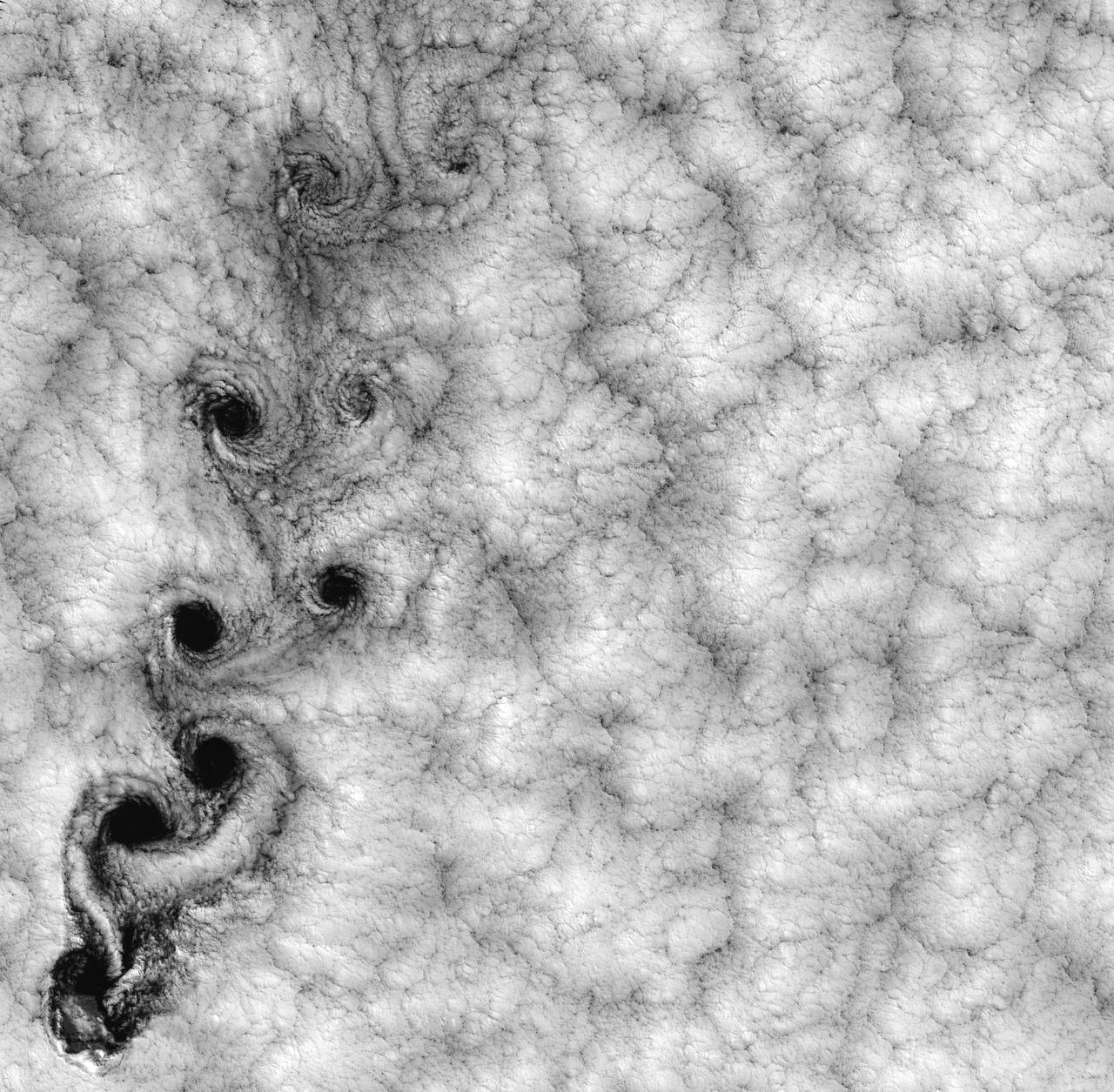
NASA image acquired September 15, 1999 This Landsat 7 image of clouds off the Chilean coast near the Juan Fernandez Islands (also known as the Robinson Crusoe Islands) on September 15, 1999, shows a unique pattern called a “von Karman vortex street.” This pattern has long been studied in the laboratory, where the vortices are created by oil flowing past a cylindrical obstacle, making a string of vortices only several tens of centimeters long. Study of this classic “flow past a circular cylinder” has been very important in the understanding of laminar and turbulent fluid flow that controls a wide variety of phenomena, from the lift under an aircraft wing to Earth’s weather. Here, the cylinder is replaced by Alejandro Selkirk Island (named after the true “Robinson Crusoe,” who was stranded here for many months in the early 1700s). The island is about 1.5 km in diameter, and rises 1.6 km into a layer of marine stratocumulus clouds. This type of cloud is important for its strong cooling of the Earth’s surface, partially counteracting the Greenhouse warming. An extended, steady equatorward wind creates vortices with clockwise flow off the eastern edge and counterclockwise flow off the western edge of the island. The vortices grow as they advect hundreds of kilometers downwind, making a street 10,000 times longer than those made in the laboratory. Observing the same phenomenon extended over such a wide range of sizes dramatizes the “fractal” nature of atmospheric convection and clouds. Fractals are characteristic of fluid flow and other dynamic systems that exhibit “chaotic” motions. Both clockwise and counter-clockwise vortices are generated by flow around the island. As the flow separates from the island’s leeward (away from the source of the wind) side, the vortices “swallow” some of the clear air over the island. (Much of the island air is cloudless due to a local “land breeze” circulation set up by the larger heat capacity of the waters surrounding the island.) The “swallowed” gulps of clear island air get carried along within the vortices, but these are soon mixed into the surrounding clouds. Landsat is unique in its ability to image both the small-scale eddies that mix clear and cloudy air, down to the 30 meter pixel size of Landsat, but also having a wide enough field-of-view, 180 km, to reveal the connection of the turbulence to large-scale flows such as the subtropical oceanic gyres. Landsat 7, with its new onboard digital recorder, has extended this capability away from the few Landsat ground stations to remote areas such as Alejandro Island, and thus is gradually providing a global dynamic picture of evolving human-scale phenomena. For more details on von Karman vortices, refer to <a href="http://climate.gsfc.nasa.gov/~cahalan" rel="nofollow">climate.gsfc.nasa.gov/~cahalan</a>. Image and caption courtesy Bob Cahalan, NASA GSFC Instrument: Landsat 7 - ETM+ Credit: NASA/GSFC/Landsat <b><a href="http://www.nasa.gov/centers/goddard/home/index.html" rel="nofollow">NASA Goddard Space Flight Center</a></b> enables NASA’s mission through four scientific endeavors: Earth Science, Heliophysics, Solar System Exploration, and Astrophysics. Goddard plays a leading role in NASA’s accomplishments by contributing compelling scientific knowledge to advance the Agency’s mission. <b>Follow us on <a href="http://twitter.com/NASA_GoddardPix" rel="nofollow">Twitter</a></b> <b>Join us on <a href="http://www.facebook.com/pages/Greenbelt-MD/NASA-Goddard/395013845897?ref=tsd" rel="nofollow">Facebook</a></b>