
Perovskite Solar Cells
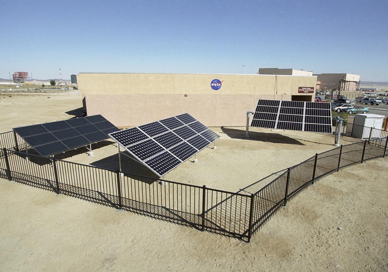
The 5 KW, state-of-the-art solar demonstration site at NASA Dryden is validating earthly use of solar cells developed for NASA's Helios solar-electric aircraft.

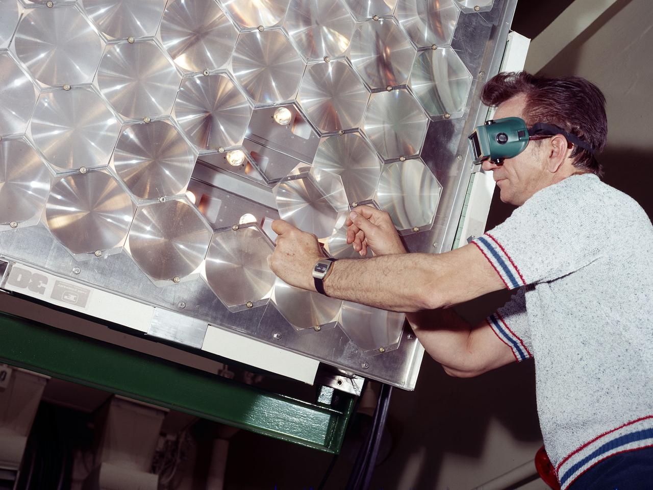
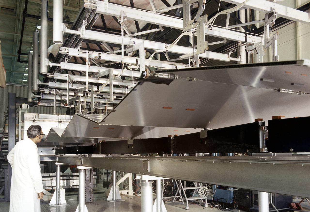
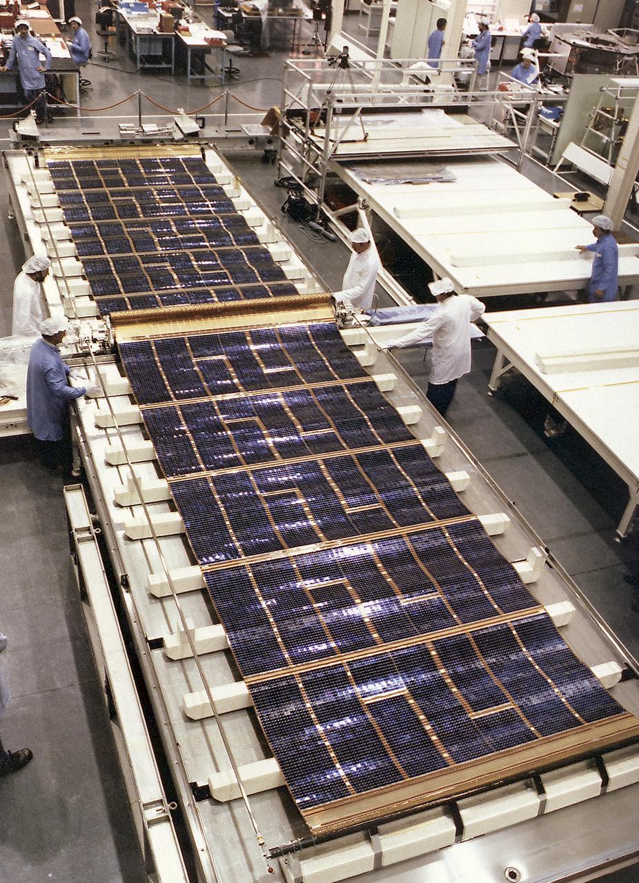
Adolph Spakowski, head of the Photovoltaic Fundamentals Section at the National Aeronautics and Space Administration (NASA) Lewis Research Center, illustrated the difference between conventional silicon solar cells (rear panel) and the new thin-film cells. The larger, flexible thin-film cells in the foreground were evaluated by Lewis energy conversion specialists for possible future space use. The conventional solar cells used on most spacecraft at the time were both delicate and heavy. For example, the Mariner IV spacecraft required 28,000 these solar cells for its flyby of Mars in 1964. NASA Lewis began investigating cadmium sulfide thin-film solar cells in 1961. The thin-film cells were made by heating semiconductor material until it evaporated. The vapor was then condensed onto an electricity-producing film only one-thousandth of an inch thick. The physical flexibility of the new thin-film cells allowed them to be furled, or rolled up, during launch. Spakowski led an 18-month test program at Lewis to investigate the application of cadmium sulfide semiconductors on a light metallized substrate. The new thin-film solar cells were tested in a space simulation chamber at a simulated altitude of 200 miles. Sunlight was recreated by a 5000-watt xenon light. Two dozen cells were exposed to 15 minutes of light followed by 15 minutes of darkness to test their durability in the constantly changing illumination of Earth orbit.
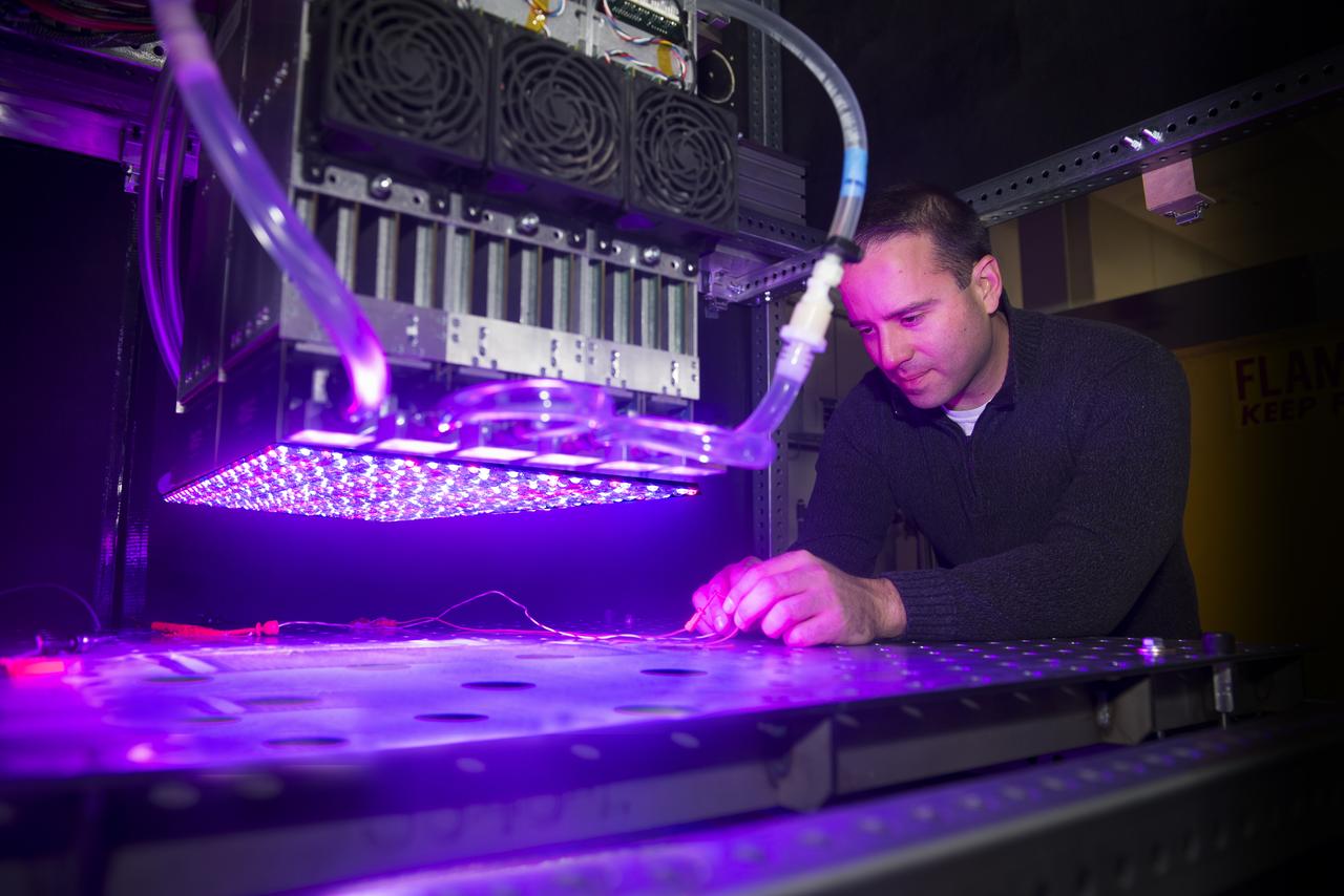
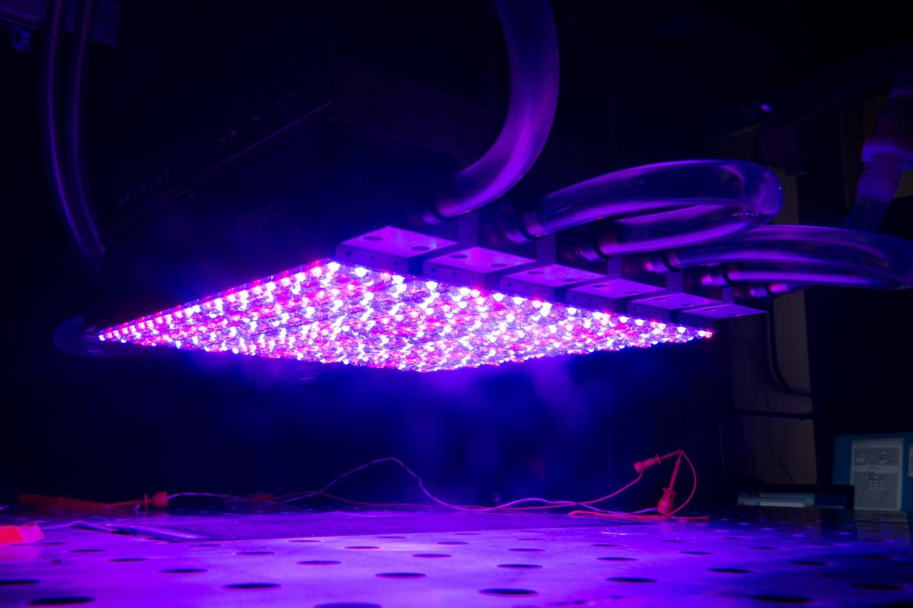
NASA Glenn's new LED solar simulator was developed by Angstrom Designs and UC Santa Barbara under a Small Business Innovative Research program to test the next generation of high-efficiency space solar cells for future missions. The new simulator contains over 1500 individually adjustable light sources, most of which emit light invisible to the human eye, to cover a 10 x10 foot area.
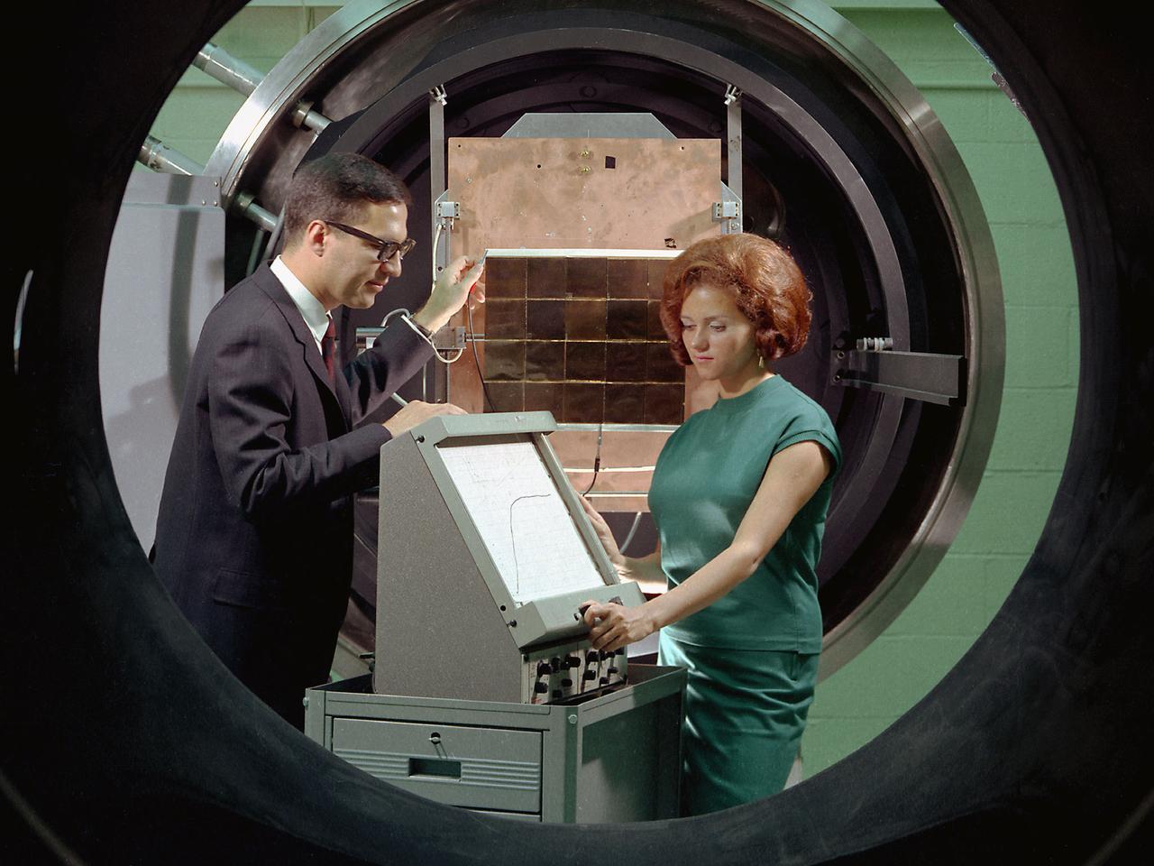
George Mazaris, works with an assistant to obtain the preliminary measurements of cadmium sulfide thin-film solar cells being tested in the Space Environmental Chamber at the National Aeronautics and Space Administration (NASA) Lewis Research Center. Lewis’ Photovoltaic Fundamentals Section was investigating thin-film alternatives to the standard rigid and fragile solar cells. The cadmium sulfide semiconductors were placed in a light, metallized substrate that could be rolled or furled during launch. The main advantage of the thin-film solar cells was their reduced weight. Lewis researchers, however, were still working on improving the performance of the semiconductor. The new thin-film solar cells were tested in a space simulation chamber in the CW-6 test cell in the Engine Research Building. The chamber created a simulated altitude of 200 miles. Sunlight was simulated by a 5000-watt xenon light. Some two dozen cells were exposed to 15 minutes of light followed by 15 minutes of darkness to test their durability in the constantly changing illumination of Earth orbit. This photograph was taken for use in a NASA recruiting publication.

Researcher Susan Johnson and a mechanic examine a flat-plate solar collector in the Solar Simulator Cell in the High Temperature Composites Laboratory at the National Aeronautics and Space Administration (NASA) Lewis Research Center. The Solar Simulator Cell allowed the researchers to control the radiation levels, air temperature, airflow, and fluid flow. The flat-plate collector, seen in a horizontal position here, was directed at the solar simulator, seen above Johnson, during the tests. Lewis researchers were studying the efficiency of various flat- plate solar collector designs in the 1970s for temperature control systems in buildings. The collectors consisted of a cover material, absorber plate, and parallel flow configuration. The collector’s absorber material and coating, covers, honeycomb material, mirrors, vacuum, and tube attachment could all be modified. Johnson’s study analyzed 35 collectors. Johnson, a lifelong pilot, joined NASA Lewis in 1974. The flat-plate solar collectors, seen here, were her first research project. Johnson also investigated advanced heat engines for general aviation and evaluated variable geometry combustors and liners. Johnson earned the Cleveland Technical Society’s Technical Achievement Award in 1984.
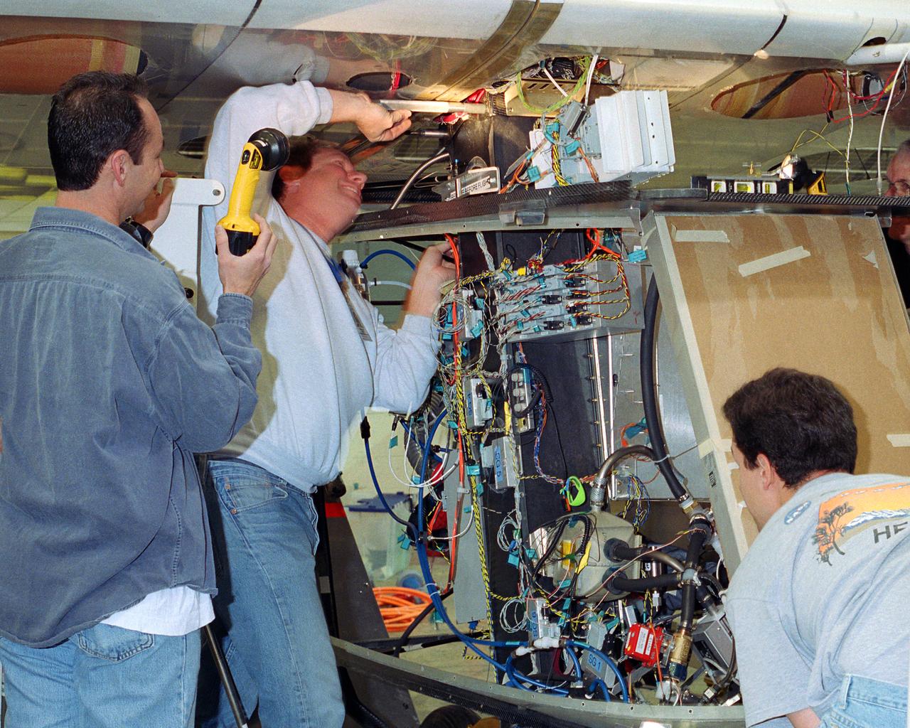
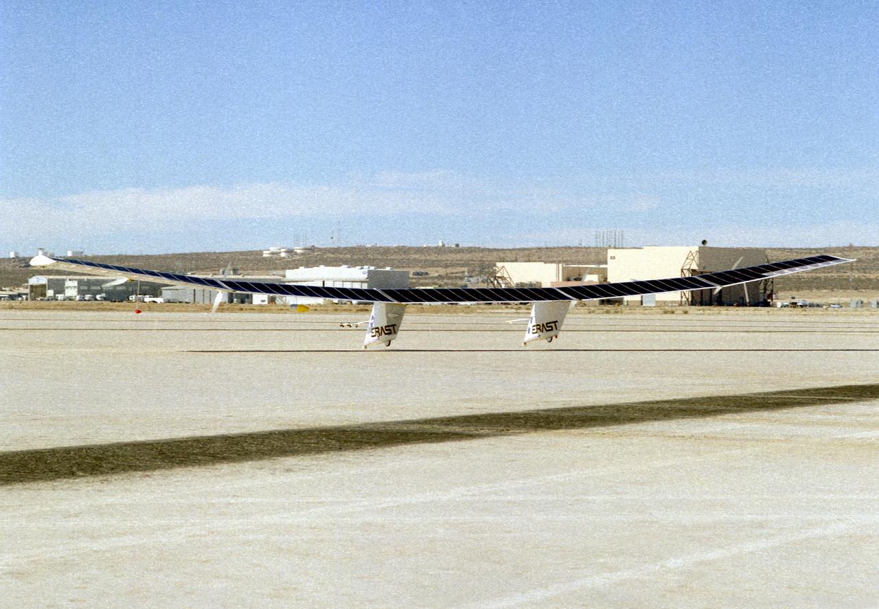
Aerovironment technicians carefully line up attachments as a fuel cell electrical system is installed on the Helios Prototype solar powered flying wing. The fuel cell system will power the aircraft at night during NASA-sponsored long-endurance demonstration flight in the summer of 2003.
NASA Glenn's new LED solar simulator was developed by Angstrom Designs and UC Santa Barbara under a Small Business Innovative Research program to test the next generation of high-efficiency space solar cells for future missions. The new simulator contains over 1500 individually adjustable light sources, most of which emit light invisible to the human eye, to cover a 10 x10 foot area.
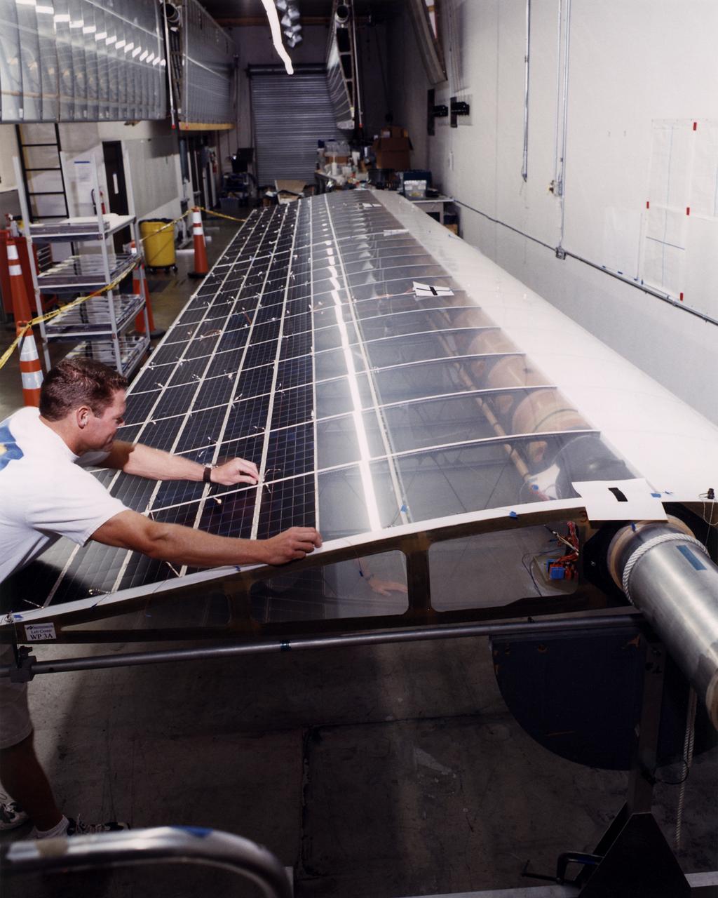
Technician Marshall MacCready carefully lays a panel of solar cells into place on a wing section of the Helios Prototype flying wing at AeroVironment's Design Development Center in Simi Valley, California. The bi-facial cells, manufactured by SunPower, Inc., of Sunnyvale, California, are among 64,000 solar cells which have been installed on the solar-powered aircraft to provide electricity to its 14 motors and operating systems.
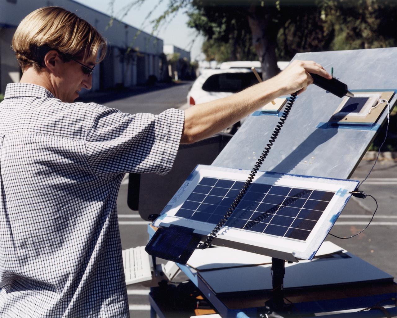
A technician at AeroVironment's Design Development Center in Simi Valley, California, checks a panel of silicon solar cells for conductivity and voltage. The bi-facial cells, fabricated by SunPower, Inc., of Sunnyvale, California, are among 64,000 solar cells which have been installed on the Helios Prototype solar-powered aircraft to provide power to its 14 electric motors and operating systems.
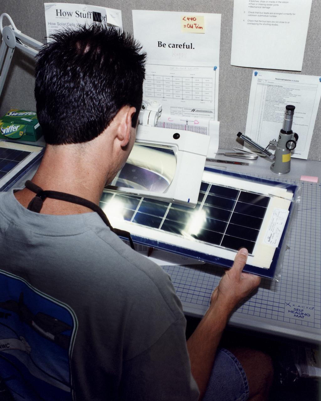
An engineer at AeroVironment's Design Development Center in Simi Valley, California, closely inspects a set of silicon solar cells for potential defects. The cells, fabricated by SunPower, Inc., of Sunnyvale, California, are among 64,000 solar cells which have been installed on the Helios Prototype solar-powered aircraft to provide power to its 14 electric motors and operating systems.
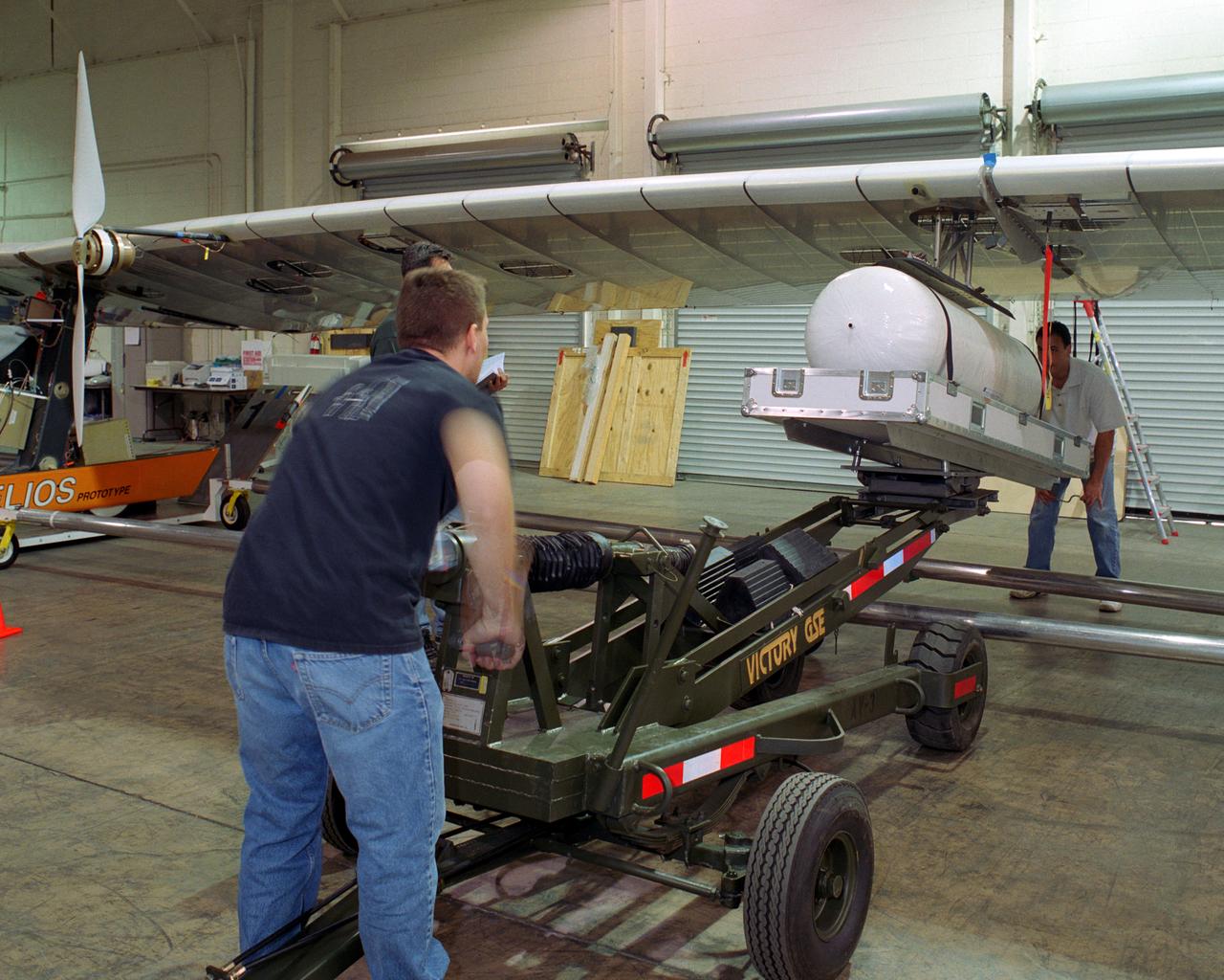
Technicians for AeroVironment, Inc., jack up a pressure tank to the wing of the Helios Prototype solar-electric flying wing. The tank carries pressurized hydrogen to fuel an experimental fuel cell system that powered the aircraft at night during an almost two-day long-endurance flight demonstration in the summer of 2003.
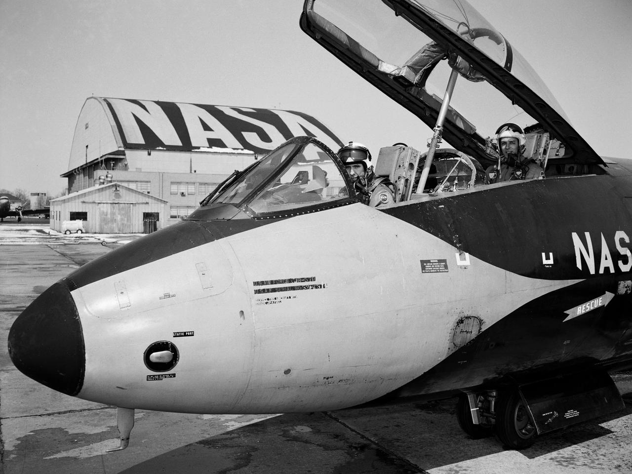
Pilot Earle Boyer and researcher Henry Brandhorst prepare for a solar cell calibration flight in a Martin B-57B Canberra at the National Aeronautics and Space Administration (NASA) Lewis Research Center. Lewis was in the early stages of decades-long energy conversion and space power research effort. Brandhorst, a member of the Chemistry and Energy Conversion Division, led a team of Lewis researchers in a quest to develop new power sources to sustain spacecraft in orbit. Solar cells proved to be an important source of energy, but researchers discovered that their behavior varied at different atmospheric levels. Their standardization and calibration were critical. Brandhorst initiated a standardized way to calibrate solar cells in the early 1960s using the B-57B aircraft. The pilots would take the aircraft up into the troposphere and open the solar cell to the sunlight. The aircraft would steadily descend while instruments recorded how much energy was being captured by the solar cell. From this data, Brandhorst could determine the estimated power for a particular solar cell at any altitude. Pilot Earle Boyer joined NASA Lewis in October 1962. He had flown Convair F-102 Delta Dagger fighters in the Air Force and served briefly in the National Guard before joining the Langley Research Center. Boyer was only at Langley a few months before he transferred to Cleveland. He flew the B-57B, a Convair F-106 Delta Dart, Gulfstream G-1 with an experimental turboprop, Learjet and many other aircraft over the next 32 years at Lewis.
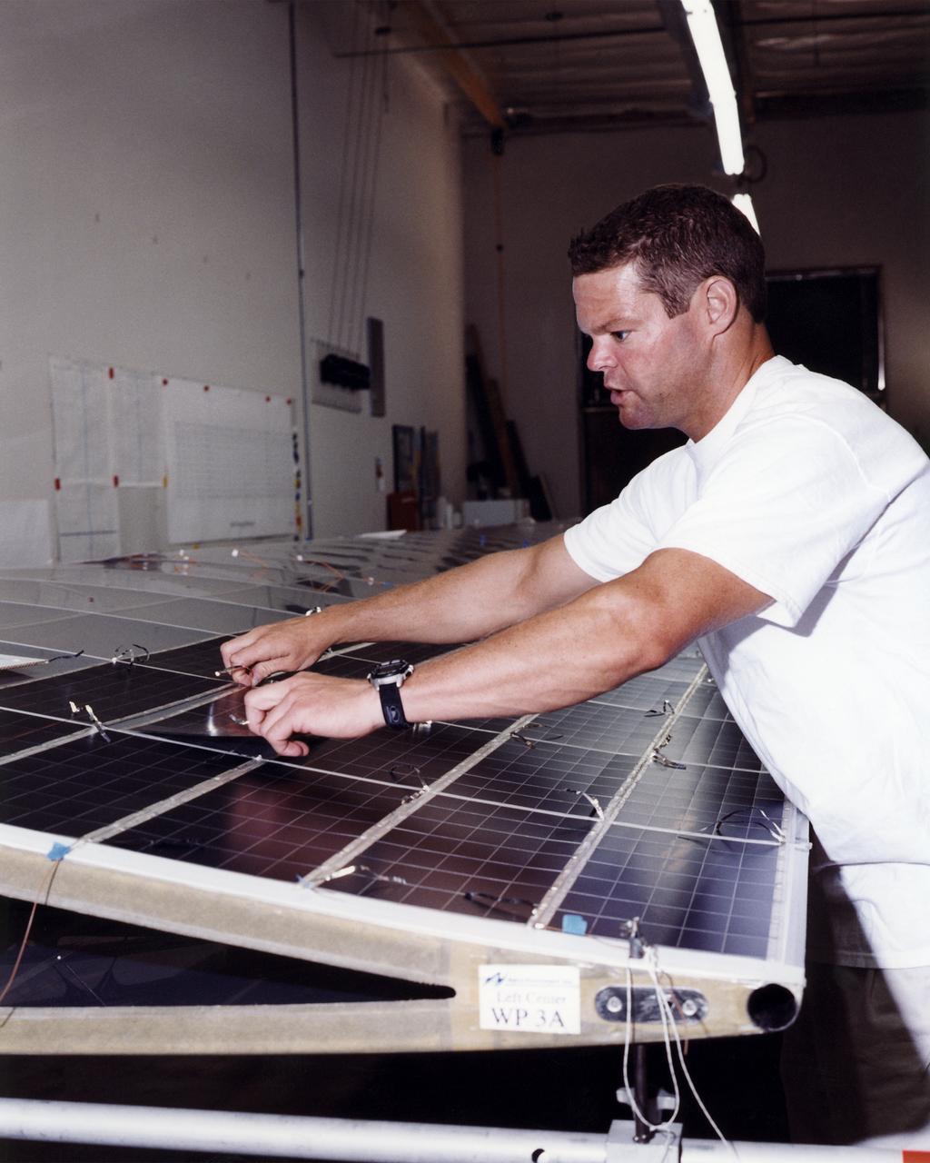
Technician Marshall MacCready carefully lays a panel of solar cells into place on a wing section of the Helios Prototype flying wing at AeroVironment's Design Development Center in Simi Valley, California. More than 1,800 panels containing some 64,000 bi-facial cells, fabricated by SunPower, Inc., of Sunnyvale, California, have been installed on the solar-powered aircraft to provide electricity to its 14 motors and operating systems.
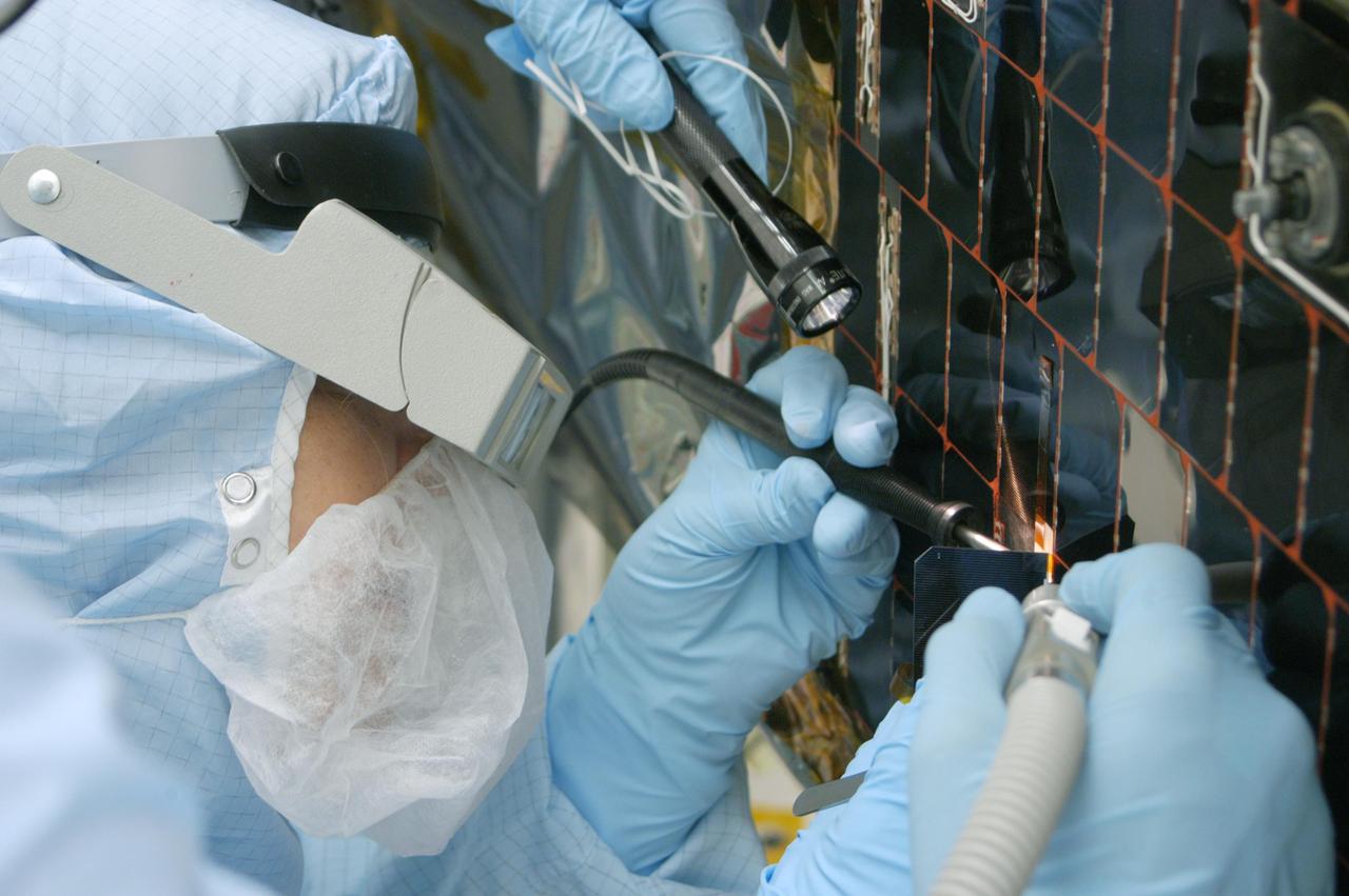
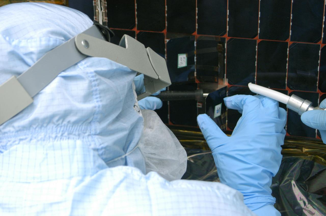
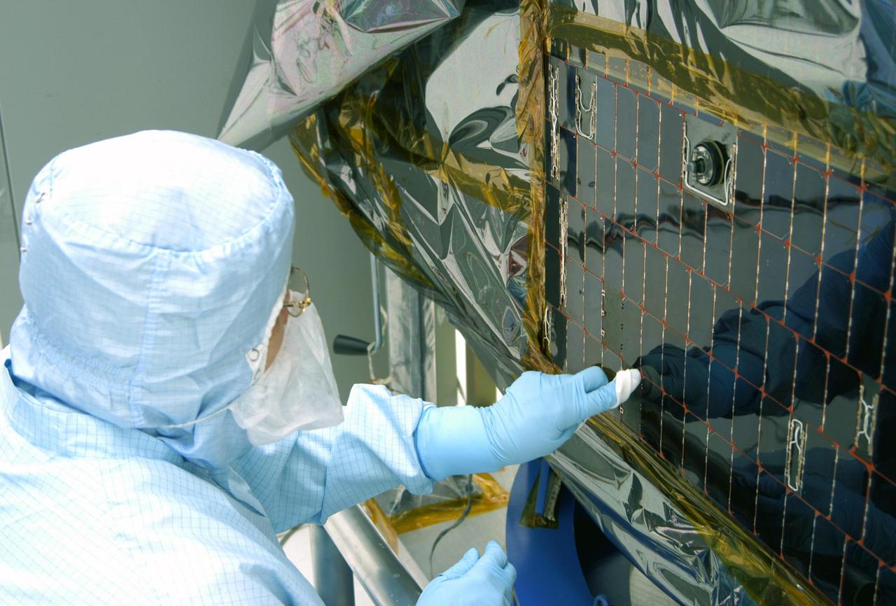
KENNEDY SPACE CENTER, FLA. - In the clean room at NASA’s Hangar AE on Cape Canaveral Air Force Station (CCAFS), a Spectrolab technician, Anna Herrera, removes one of the solar cells that will be replaced on the Swift spacecraft’s solar array. Swift is a first-of-its-kind, multi-wavelength observatory dedicated to the study of gamma-ray burst (GRB) science. Its three instruments will work together to observe GRBs and afterglows in the gamma-ray, X-ray, ultraviolet and optical wavebands. The main mission objectives for Swift are to determine the origin of gamma-ray bursts, classify gamma-ray bursts and search for new types, determine how the blast wave evolves and interacts with the surroundings, use gamma-ray bursts to study the early universe and perform the first sensitive hard X-ray survey of the sky. Swift is scheduled to launch Oct. 26 from Launch Pad 17-A, CCAFS, on a Boeing Delta 7320 rocket.
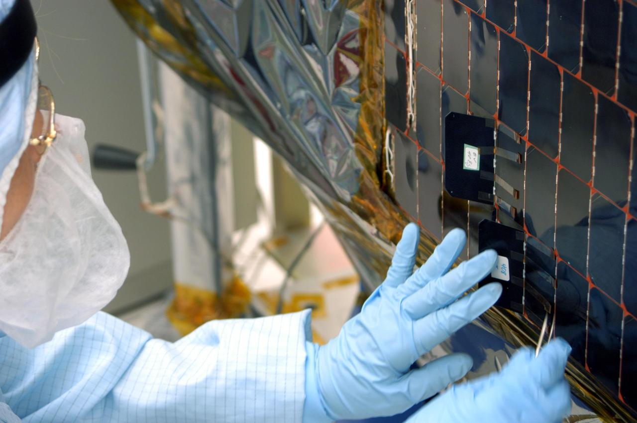
KENNEDY SPACE CENTER, FLA. - In the clean room at NASA’s Hangar AE on Cape Canaveral Air Force Station (CCAFS), a Spectrolab technician, Anna Herrera, places a new solar cell on the Swift spacecraft’s solar array. Swift is a first-of-its-kind, multi-wavelength observatory dedicated to the study of gamma-ray burst (GRB) science. Its three instruments will work together to observe GRBs and afterglows in the gamma-ray, X-ray, ultraviolet and optical wavebands. The main mission objectives for Swift are to determine the origin of gamma-ray bursts, classify gamma-ray bursts and search for new types, determine how the blast wave evolves and interacts with the surroundings, use gamma-ray bursts to study the early universe and perform the first sensitive hard X-ray survey of the sky. Swift is scheduled to launch Oct. 26 from Launch Pad 17-A, CCAFS, on a Boeing Delta 7320 rocket.
KENNEDY SPACE CENTER, FLA. - In the clean room at NASA’s Hangar AE on Cape Canaveral Air Force Station (CCAFS), a Spectrolab technician, Anna Herrera, places a new solar cell on the Swift spacecraft’s solar array. Swift is a first-of-its-kind, multi-wavelength observatory dedicated to the study of gamma-ray burst (GRB) science. Its three instruments will work together to observe GRBs and afterglows in the gamma-ray, X-ray, ultraviolet and optical wavebands. The main mission objectives for Swift are to determine the origin of gamma-ray bursts, classify gamma-ray bursts and search for new types, determine how the blast wave evolves and interacts with the surroundings, use gamma-ray bursts to study the early universe and perform the first sensitive hard X-ray survey of the sky. Swift is scheduled to launch Oct. 26 from Launch Pad 17-A, CCAFS, on a Boeing Delta 7320 rocket.
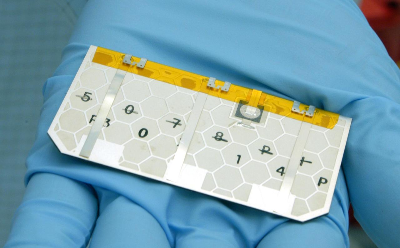
KENNEDY SPACE CENTER, FLA. - A closeup of one of the solar cells that will be removed and replaced on the Swift spacecraft’s solar array. Swift is a first-of-its-kind, multi-wavelength observatory dedicated to the study of gamma-ray burst (GRB) science. Its three instruments will work together to observe GRBs and afterglows in the gamma-ray, X-ray, ultraviolet and optical wavebands. The main mission objectives for Swift are to determine the origin of gamma-ray bursts, classify gamma-ray bursts and search for new types, determine how the blast wave evolves and interacts with the surroundings, use gamma-ray bursts to study the early universe and perform the first sensitive hard X-ray survey of the sky. Swift is scheduled to launch Oct. 26 from Launch Pad 17-A, CCAFS, on a Boeing Delta 7320 rocket.
KENNEDY SPACE CENTER, FLA. - In the clean room at NASA’s Hangar AE on Cape Canaveral Air Force Station (CCAFS), a Spectrolab technician, Anna Herrera, points to the two new solar cells removed and replaced on the Swift spacecraft’s solar array. Swift is a first-of-its-kind, multi-wavelength observatory dedicated to the study of gamma-ray burst (GRB) science. Its three instruments will work together to observe GRBs and afterglows in the gamma-ray, X-ray, ultraviolet and optical wavebands. The main mission objectives for Swift are to determine the origin of gamma-ray bursts, classify gamma-ray bursts and search for new types, determine how the blast wave evolves and interacts with the surroundings, use gamma-ray bursts to study the early universe and perform the first sensitive hard X-ray survey of the sky. Swift is scheduled to launch Oct. 26 from Launch Pad 17-A, CCAFS, on a Boeing Delta 7320 rocket.
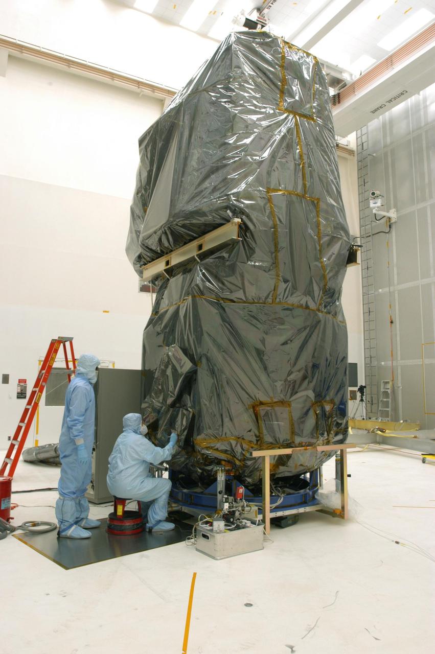
KENNEDY SPACE CENTER, FLA. - In the clean room at NASA’s Hangar AE on Cape Canaveral Air Force Station (CCAFS), Spectrolab technicians begin lifting the protective cover from the Swift spacecraft. Two of Swift’s solar cells on the solar array will be removed and replaced. Swift is a first-of-its-kind, multi-wavelength observatory dedicated to the study of gamma-ray burst (GRB) science. Its three instruments will work together to observe GRBs and afterglows in the gamma-ray, X-ray, ultraviolet and optical wavebands. The main mission objectives for Swift are to determine the origin of gamma-ray bursts, classify gamma-ray bursts and search for new types, determine how the blast wave evolves and interacts with the surroundings, use gamma-ray bursts to study the early universe and perform the first sensitive hard X-ray survey of the sky. Swift is scheduled to launch Oct. 26 from Launch Pad 17-A, CCAFS, on a Boeing Delta 7320 rocket.
CAPE CANAVERAL, Fla. – In the Space Station Processing Facility at NASA's Kennedy Space Center, workers prepare to move the final solar array wing for the International Space Station for installation on the S6 truss element. Scheduled to launch on the STS-119 mission, space shuttle Discovery will carry the S6 truss segment to complete the 361-foot-long backbone of the International Space Station. The truss includes the fourth pair of solar array wings and electronics that convert sunlight to power for the orbiting laboratory. Launch is targeted for Feb. 12, 2009. Photo credit: NASA/Troy Cryder
CAPE CANAVERAL, Fla. – In the Space Station Processing Facility at NASA's Kennedy Space Center, workers prepare to install the final solar array wing for the International Space Station onto the S6 truss element. Scheduled to launch on the STS-119 mission, space shuttle Discovery will carry the S6 truss segment to complete the 361-foot-long backbone of the International Space Station. The truss includes the fourth pair of solar array wings and electronics that convert sunlight to power for the orbiting laboratory. Launch is targeted for Feb. 12, 2009. Photo credit: NASA/Troy Cryder
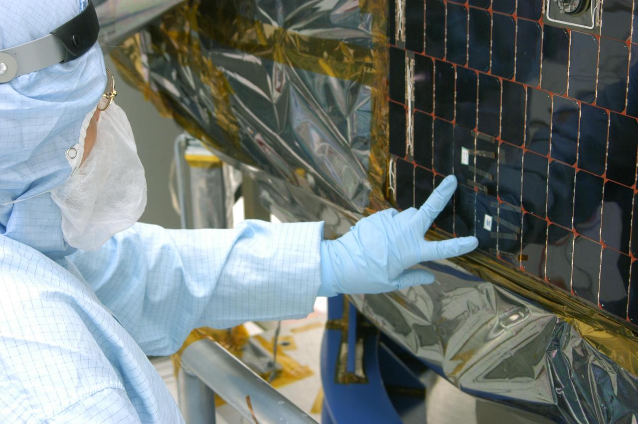
KENNEDY SPACE CENTER, FLA. - In the clean room at NASA’s Hangar AE on Cape Canaveral Air Force Station (CCAFS), a Spectrolab technician, Anna Herrera, points to an area on the Swift spacecraft’s solar array where cells will be removed and replaced. Swift is a first-of-its-kind, multi-wavelength observatory dedicated to the study of gamma-ray burst (GRB) science. Its three instruments will work together to observe GRBs and afterglows in the gamma-ray, X-ray, ultraviolet and optical wavebands. The main mission objectives for Swift are to determine the origin of gamma-ray bursts, classify gamma-ray bursts and search for new types, determine how the blast wave evolves and interacts with the surroundings, use gamma-ray bursts to study the early universe and perform the first sensitive hard X-ray survey of the sky. Swift is scheduled to launch Oct. 26 from Launch Pad 17-A, CCAFS, on a Boeing Delta 7320 rocket.
A NASA engineer installs a solar cell into a large array of solar cells.
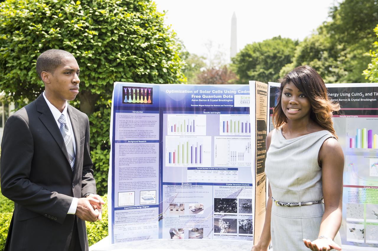
Crystal Brockington and Aaron Barron, both 18 years old, designed a more efficient and cost effective solar cell that harnesses energy without cadmium, which has been shown to be harmful to the environment. They were selected to participate in the White House Science Fair after they were awarded the High School Grand Prize at the Siemens We Can Change the World Challenge. The fourth White House Science Fair was held at the White House on May 27, 2014 and included 100 students from more than 30 different states who competed in science, technology, engineering, and math (STEM) competitions. (Photo Credit: NASA/Aubrey Gemignani)
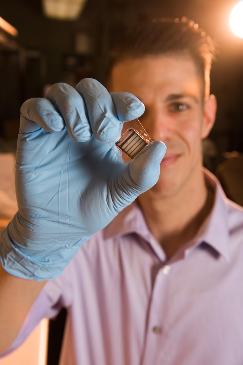
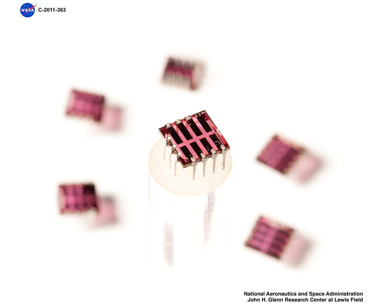
NASA Glenn researcher Tim Peshek shows off a new type of ultrathin solar cell, known as a ‘perovskite’ because of its structure. These solar cells show promise for space applications because of their high efficiency and radiation tolerance and open the door to extremely low cost and large solar arrays for spacecraft or lunar surface habitats.
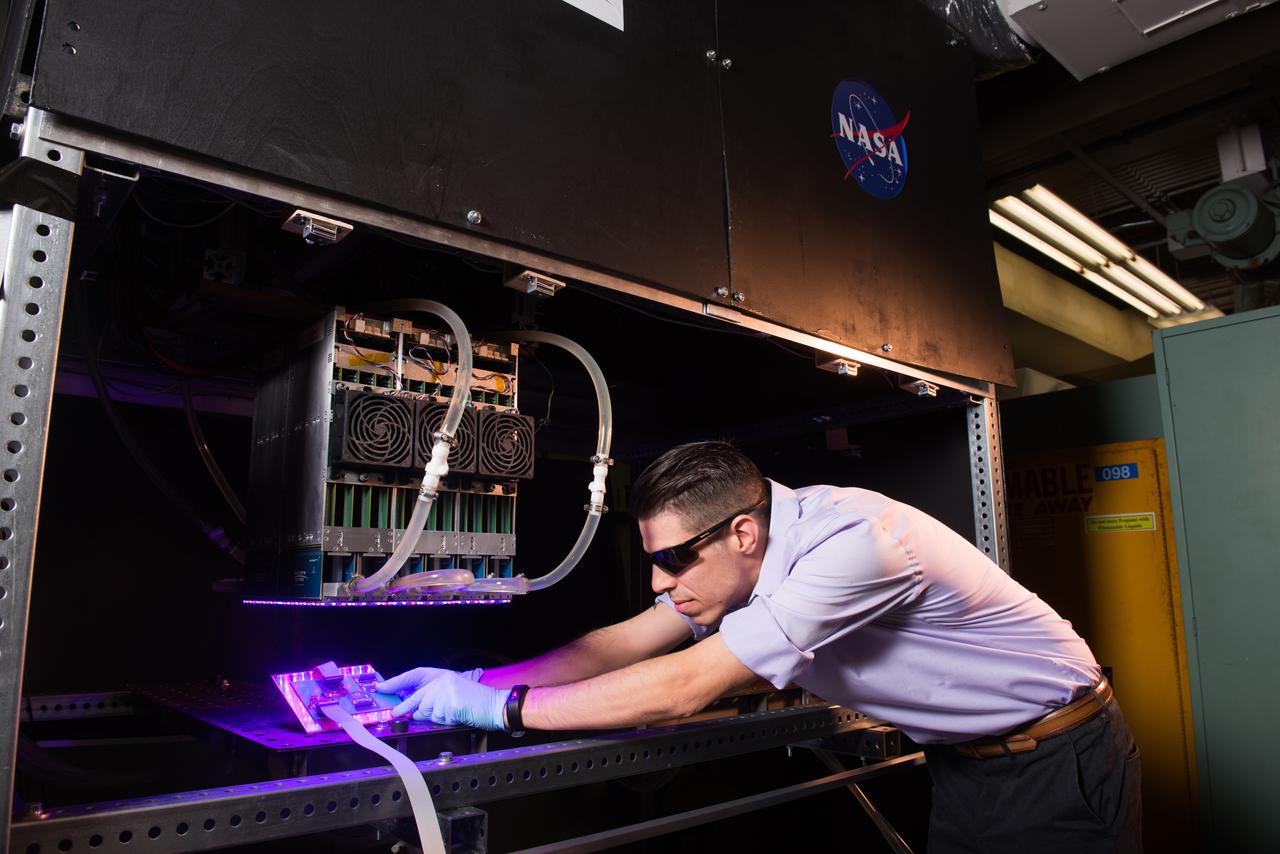
NASA Glenn researcher Tim Peshek shows off a new type of ultrathin solar cell, known as a ‘perovskite’ because of its structure. These solar cells show promise for space applications because of their high efficiency and radiation tolerance and open the door to extremely low cost and large solar arrays for spacecraft or lunar surface habitats.
NASA Glenn researcher Tim Peshek shows off a new type of ultrathin solar cell, known as a ‘perovskite’ because of its structure. These solar cells show promise for space applications because of their high efficiency and radiation tolerance and open the door to extremely low cost and large solar arrays for spacecraft or lunar surface habitats.
Photovoltaic Hardware - Prototype Organic Solar Cell Module
This is a photograph of a technician checking on a solar array wing for the Orbital Workshop as it is deployed. A solar array, consisting of two wings covered on one side with solar cells, was mounted outside the workshop to generate electrical power to augment the power generated by another solar array mounted on the solar observatory.
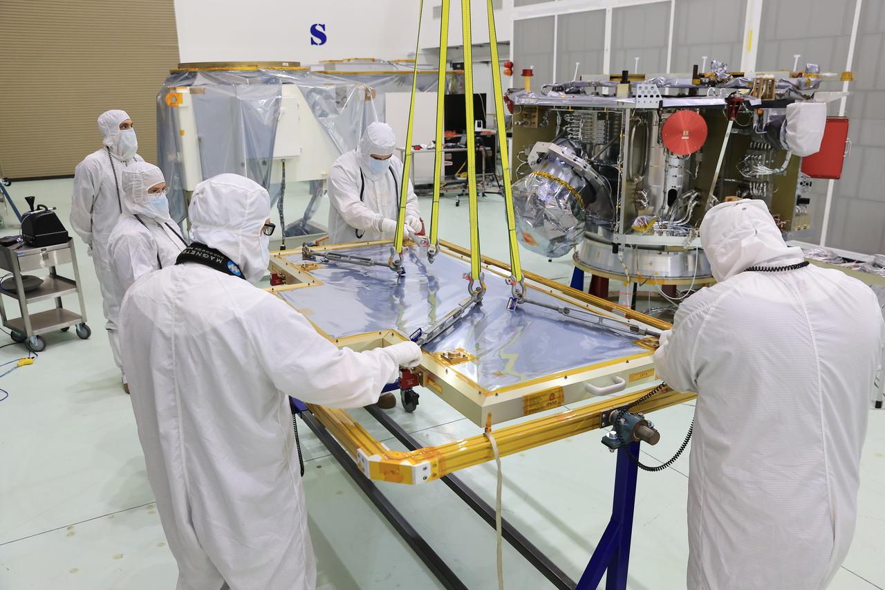
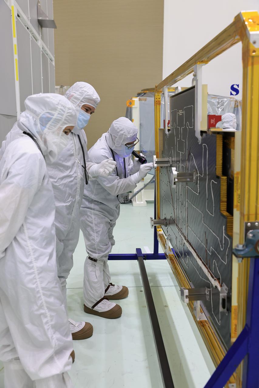
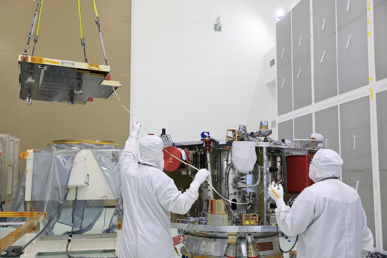
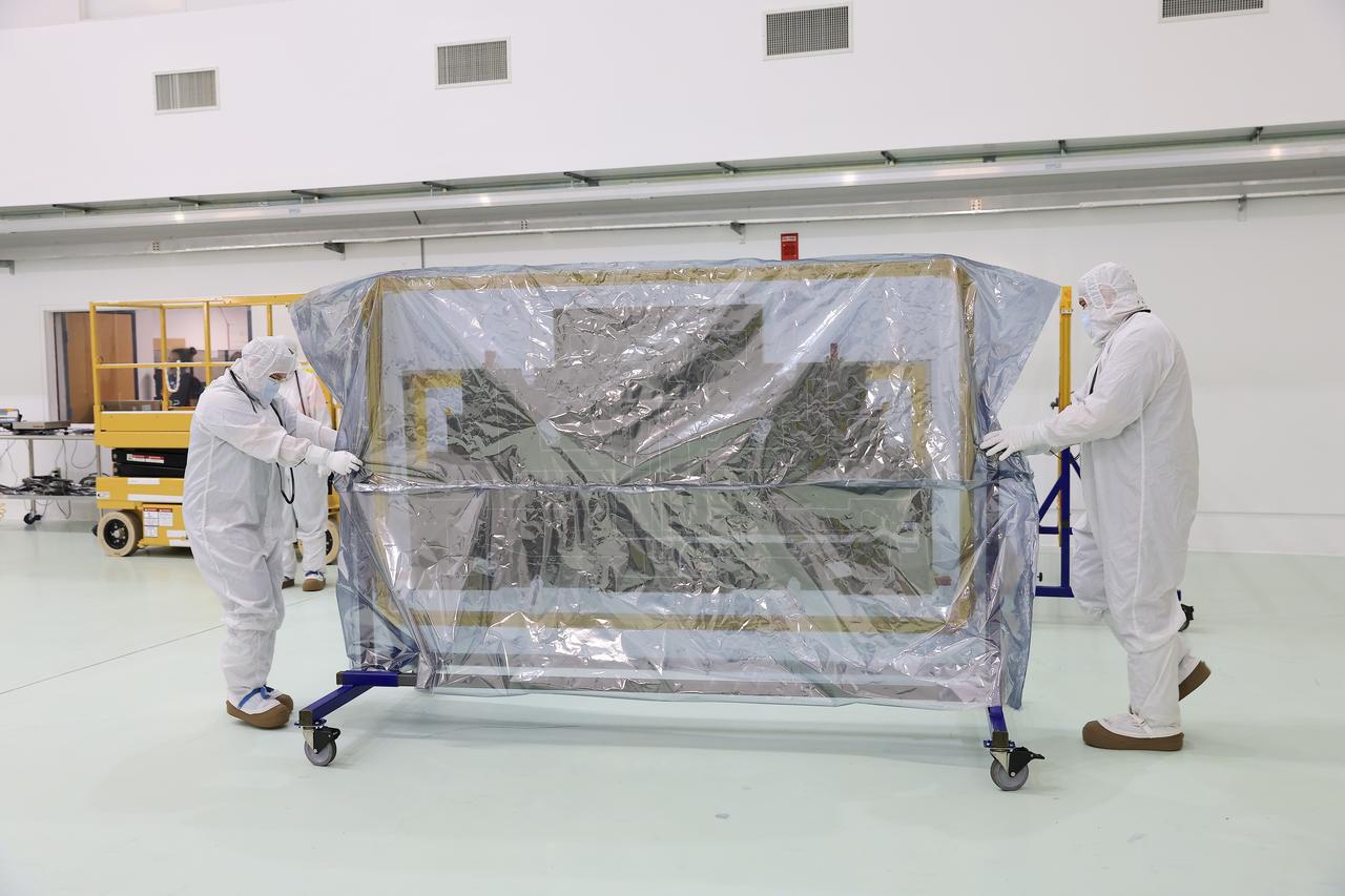
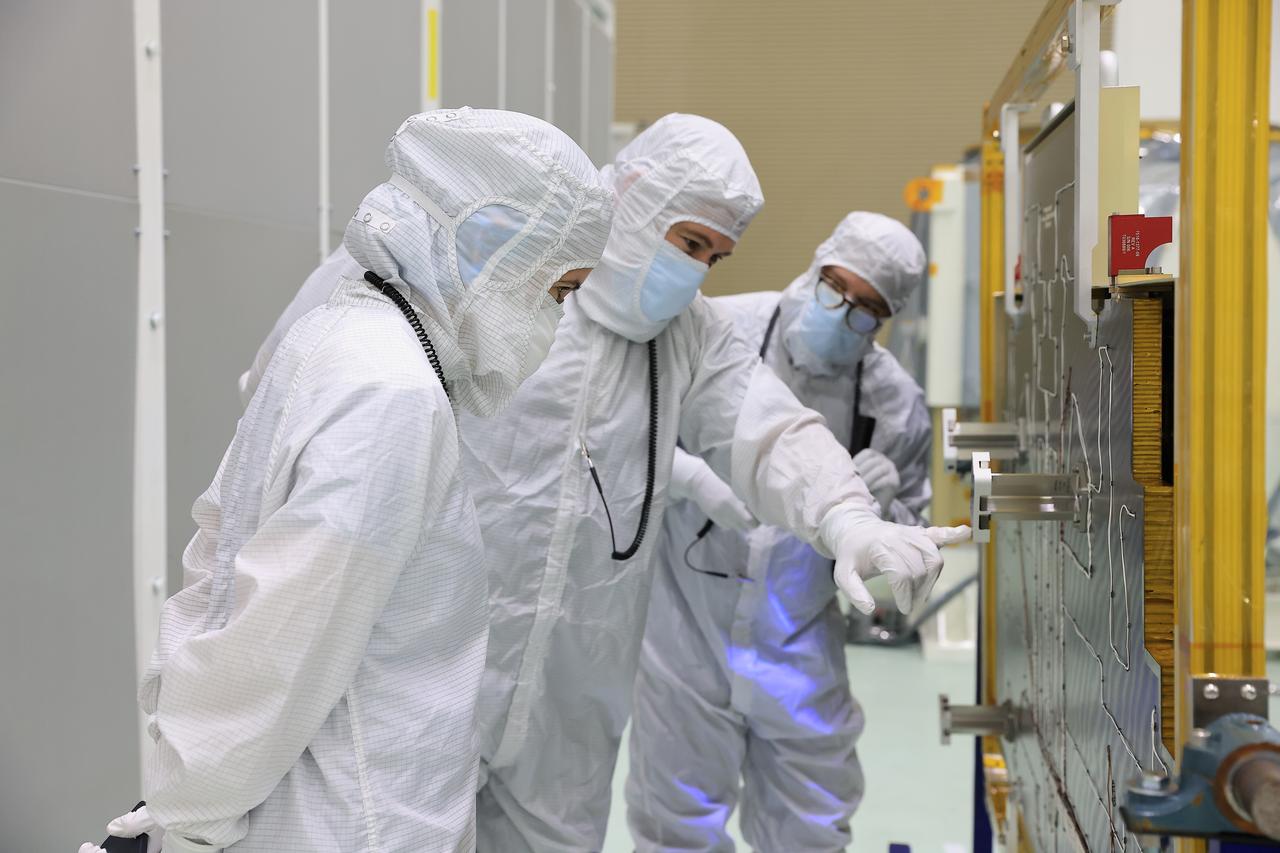
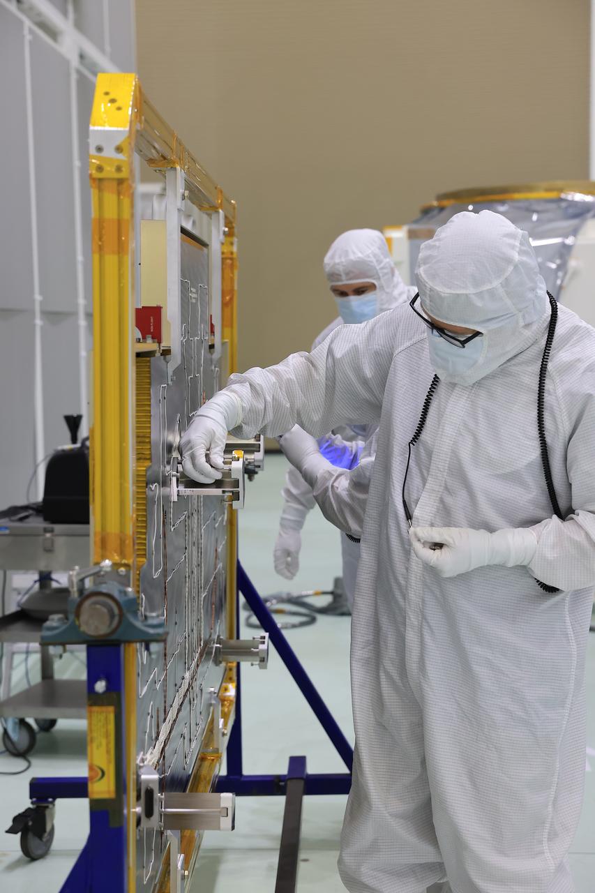
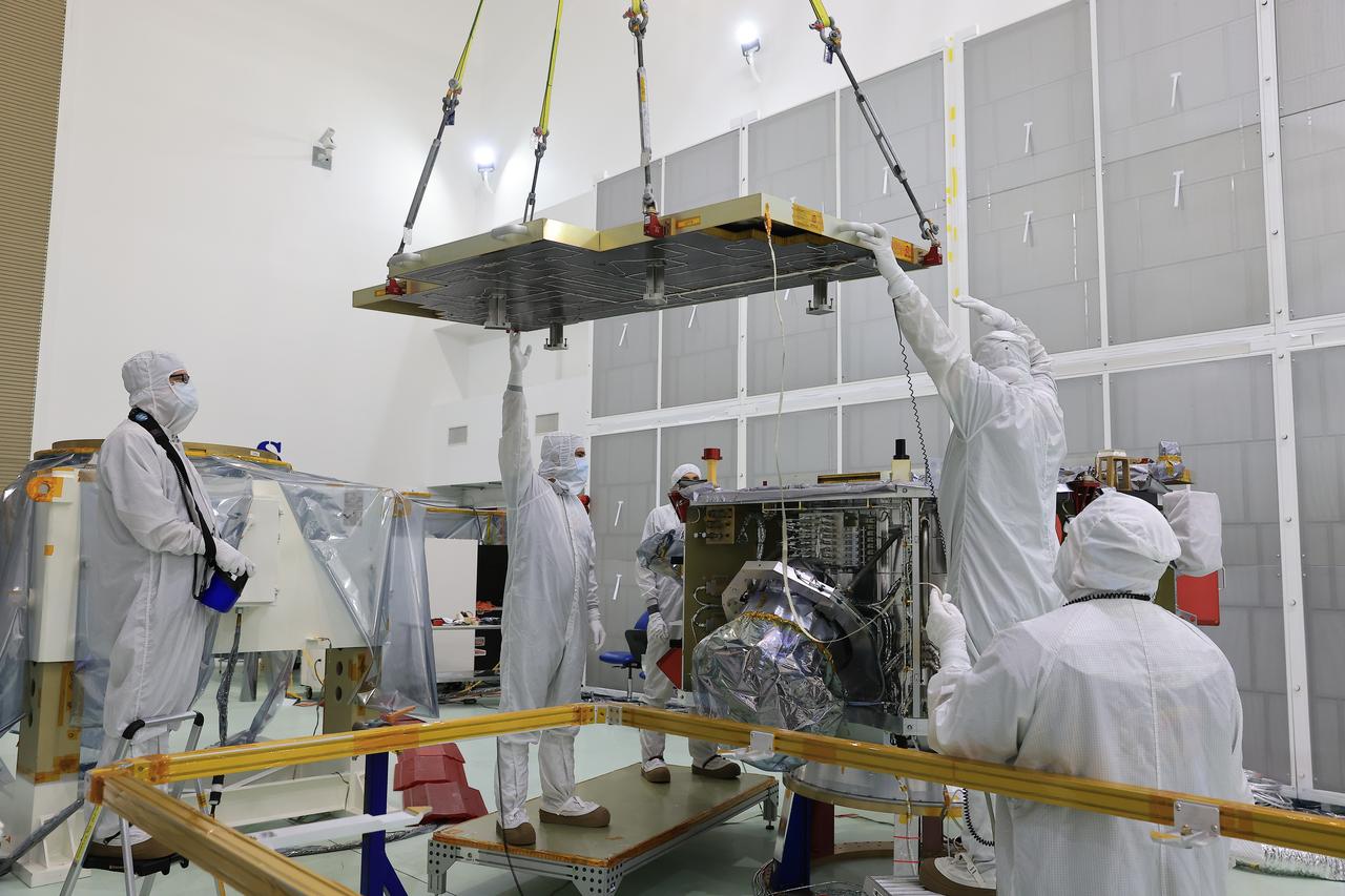
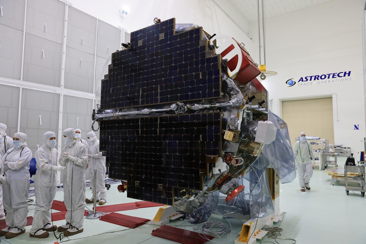
Technicians at the Astrotech Space Operations Facility near NASA’s Kennedy Space Center in Florida install the two-panel solar array on Thursday, July 17, 2025, that will help power the agency’s IMAP (Interstellar Mapping and Acceleration Probe) observatory on its upcoming journey one million miles away from Earth. Each panel of the solar array, located on the top of IMAP, consists of 16 strings of solar cells, with 36 cells per string, and combined will convert sunlight into 500 watts of power, more than enough for the observatory, which as a system uses less power than five 100-watt incandescent light bulbs.
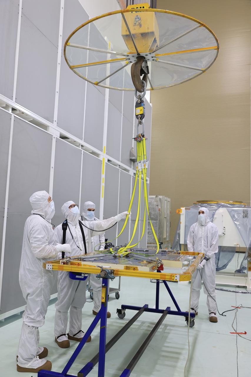
Technicians at the Astrotech Space Operations Facility near NASA’s Kennedy Space Center in Florida install the two-panel solar array on Thursday, July 17, 2025, that will help power the agency’s IMAP (Interstellar Mapping and Acceleration Probe) observatory on its upcoming journey one million miles away from Earth. Each panel of the solar array, located on the top of IMAP, consists of 16 strings of solar cells, with 36 cells per string, and combined will convert sunlight into 500 watts of power, more than enough for the observatory, which as a system uses less power than five 100-watt incandescent light bulbs.
Technicians at the Astrotech Space Operations Facility near NASA’s Kennedy Space Center in Florida install the two-panel solar array on Thursday, July 17, 2025, that will help power the agency’s IMAP (Interstellar Mapping and Acceleration Probe) observatory on its upcoming journey one million miles away from Earth. Each panel of the solar array, located on the top of IMAP, consists of 16 strings of solar cells, with 36 cells per string, and combined will convert sunlight into 500 watts of power, more than enough for the observatory, which as a system uses less power than five 100-watt incandescent light bulbs.
Technicians at the Astrotech Space Operations Facility near NASA’s Kennedy Space Center in Florida install the two-panel solar array on Thursday, July 17, 2025, that will help power the agency’s IMAP (Interstellar Mapping and Acceleration Probe) observatory on its upcoming journey one million miles away from Earth. Each panel of the solar array, located on the top of IMAP, consists of 16 strings of solar cells, with 36 cells per string, and combined will convert sunlight into 500 watts of power, more than enough for the observatory, which as a system uses less power than five 100-watt incandescent light bulbs.
Technicians at the Astrotech Space Operations Facility near NASA’s Kennedy Space Center in Florida install the two-panel solar array on Thursday, July 17, 2025, that will help power the agency’s IMAP (Interstellar Mapping and Acceleration Probe) observatory on its upcoming journey one million miles away from Earth. Each panel of the solar array, located on the top of IMAP, consists of 16 strings of solar cells, with 36 cells per string, and combined will convert sunlight into 500 watts of power, more than enough for the observatory, which as a system uses less power than five 100-watt incandescent light bulbs.
Technicians at the Astrotech Space Operations Facility near NASA’s Kennedy Space Center in Florida install the two-panel solar array on Thursday, July 17, 2025, that will help power the agency’s IMAP (Interstellar Mapping and Acceleration Probe) observatory on its upcoming journey one million miles away from Earth. Each panel of the solar array, located on the top of IMAP, consists of 16 strings of solar cells, with 36 cells per string, and combined will convert sunlight into 500 watts of power, more than enough for the observatory, which as a system uses less power than five 100-watt incandescent light bulbs.
Technicians at the Astrotech Space Operations Facility near NASA’s Kennedy Space Center in Florida install the two-panel solar array on Thursday, July 17, 2025, that will help power the agency’s IMAP (Interstellar Mapping and Acceleration Probe) observatory on its upcoming journey one million miles away from Earth. Each panel of the solar array, located on the top of IMAP, consists of 16 strings of solar cells, with 36 cells per string, and combined will convert sunlight into 500 watts of power, more than enough for the observatory, which as a system uses less power than five 100-watt incandescent light bulbs.
Technicians at the Astrotech Space Operations Facility near NASA’s Kennedy Space Center in Florida install the two-panel solar array on Thursday, July 17, 2025, that will help power the agency’s IMAP (Interstellar Mapping and Acceleration Probe) observatory on its upcoming journey one million miles away from Earth. Each panel of the solar array, located on the top of IMAP, consists of 16 strings of solar cells, with 36 cells per string, and combined will convert sunlight into 500 watts of power, more than enough for the observatory, which as a system uses less power than five 100-watt incandescent light bulbs.
Technicians at the Astrotech Space Operations Facility near NASA’s Kennedy Space Center in Florida install the two-panel solar array on Thursday, July 17, 2025, that will help power the agency’s IMAP (Interstellar Mapping and Acceleration Probe) observatory on its upcoming journey one million miles away from Earth. Each panel of the solar array, located on the top of IMAP, consists of 16 strings of solar cells, with 36 cells per string, and combined will convert sunlight into 500 watts of power, more than enough for the observatory, which as a system uses less power than five 100-watt incandescent light bulbs.
Technicians at the Astrotech Space Operations Facility near NASA’s Kennedy Space Center in Florida install the two-panel solar array on Thursday, July 17, 2025, that will help power the agency’s IMAP (Interstellar Mapping and Acceleration Probe) observatory on its upcoming journey one million miles away from Earth. Each panel of the solar array, located on the top of IMAP, consists of 16 strings of solar cells, with 36 cells per string, and combined will convert sunlight into 500 watts of power, more than enough for the observatory, which as a system uses less power than five 100-watt incandescent light bulbs.
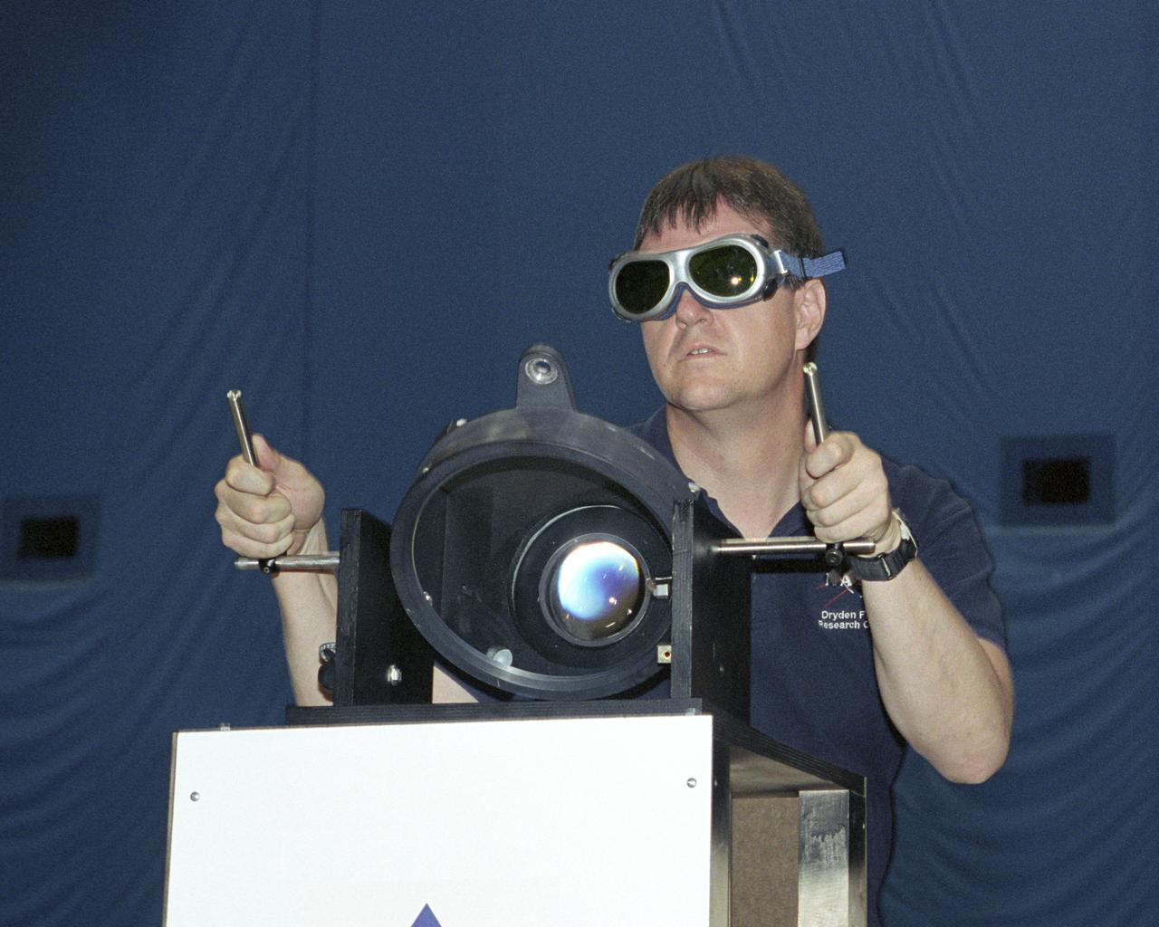
NASA Dryden project engineer Dave Bushman carefully aims the optics of a laser device at a solar cell panel on a model aircraft during the first flight demonstration of an aircraft powered by laser light.
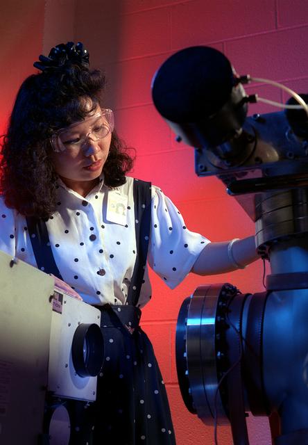
A pigment (phthalocyanine) is studied at the Marshall Materials and Processes Lab. The pigment has the ability to protect spacecraft against the harmful effects of the Sun's ultraviolet rays, and to increase the efficiency and life of solar cells.
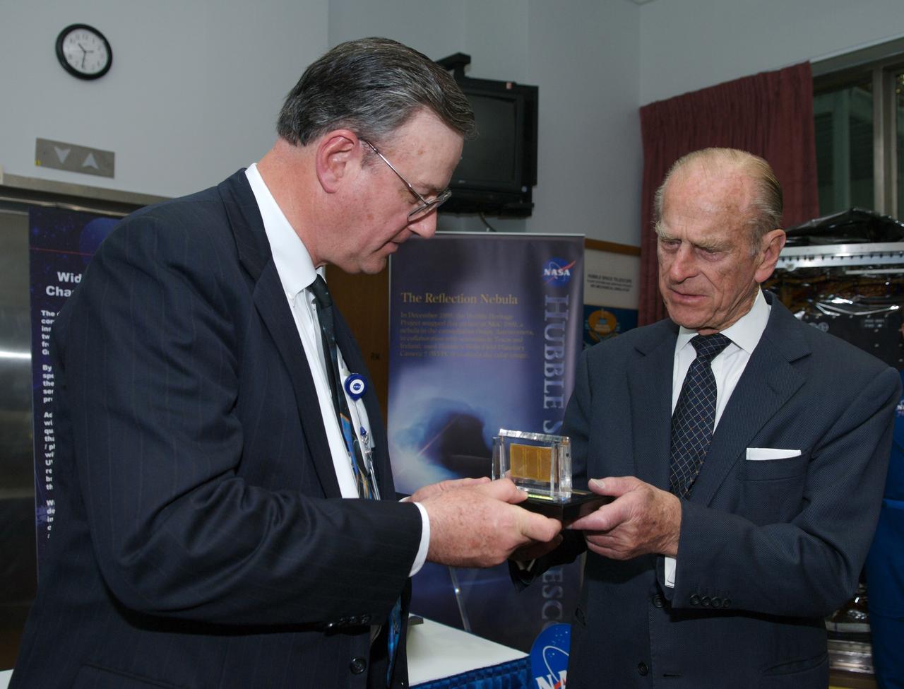
Preston Burch, left, Hubble Spece Telescope Program Manager presents Prince Philip with three solar cells returned from space during the first HST servicing mission. Photo Credit: (NASA/Chris Gunn)
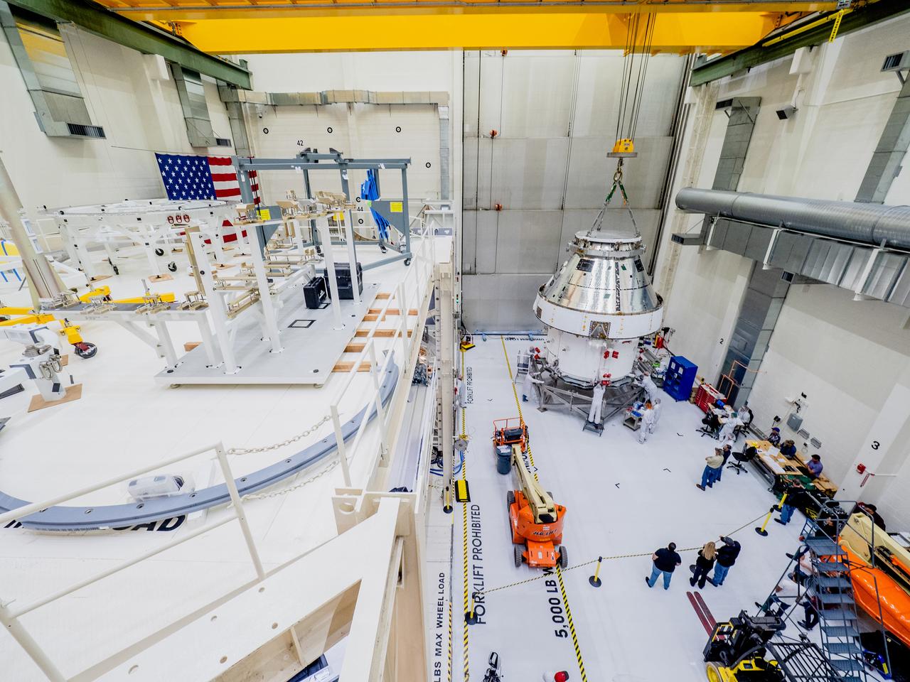
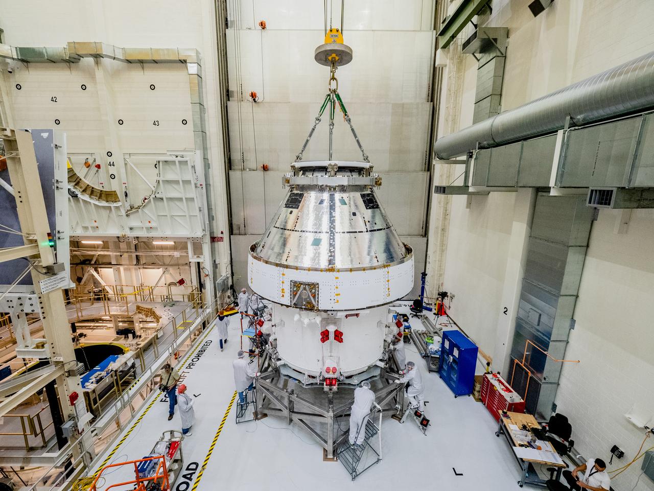
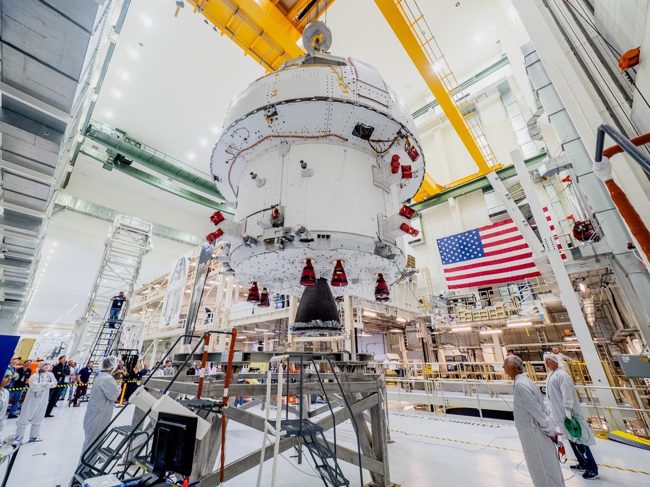
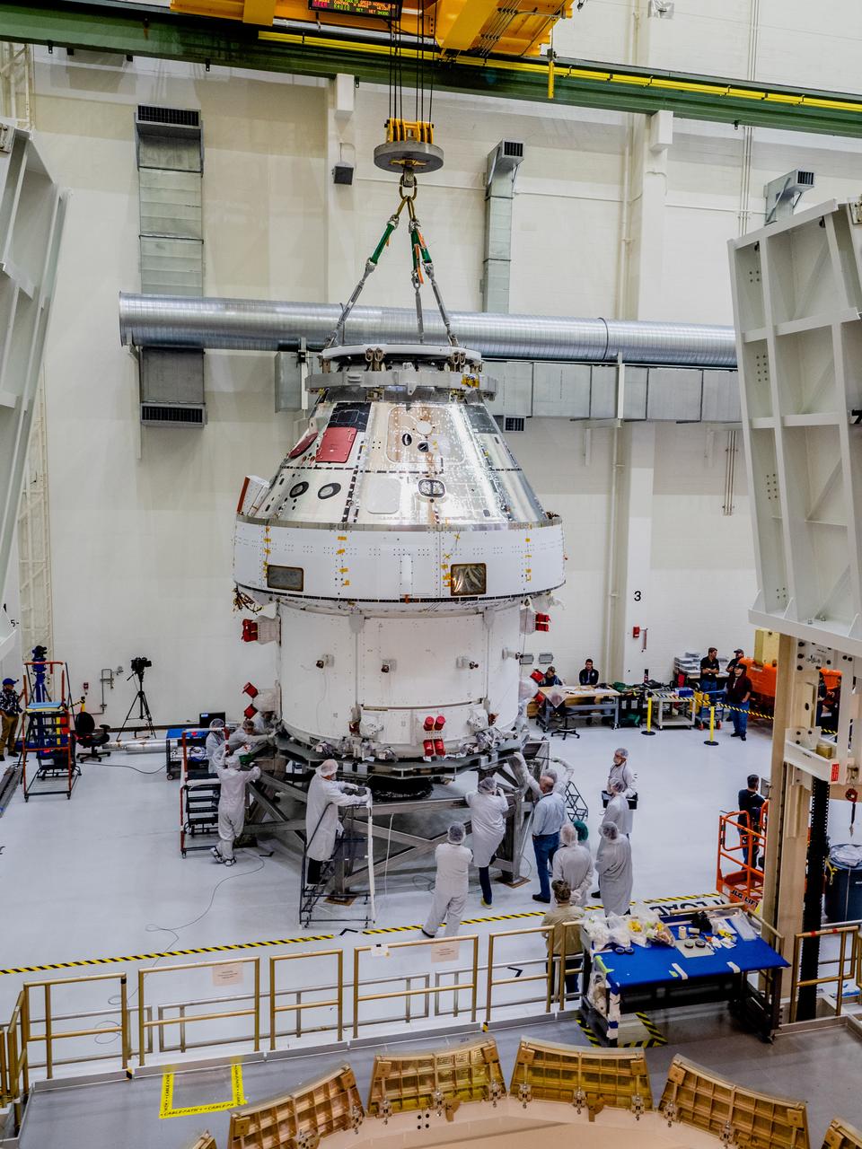
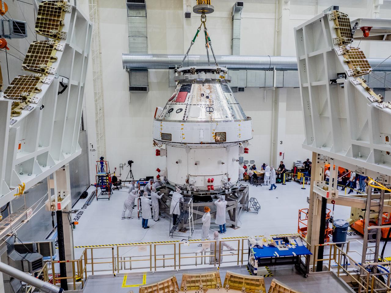
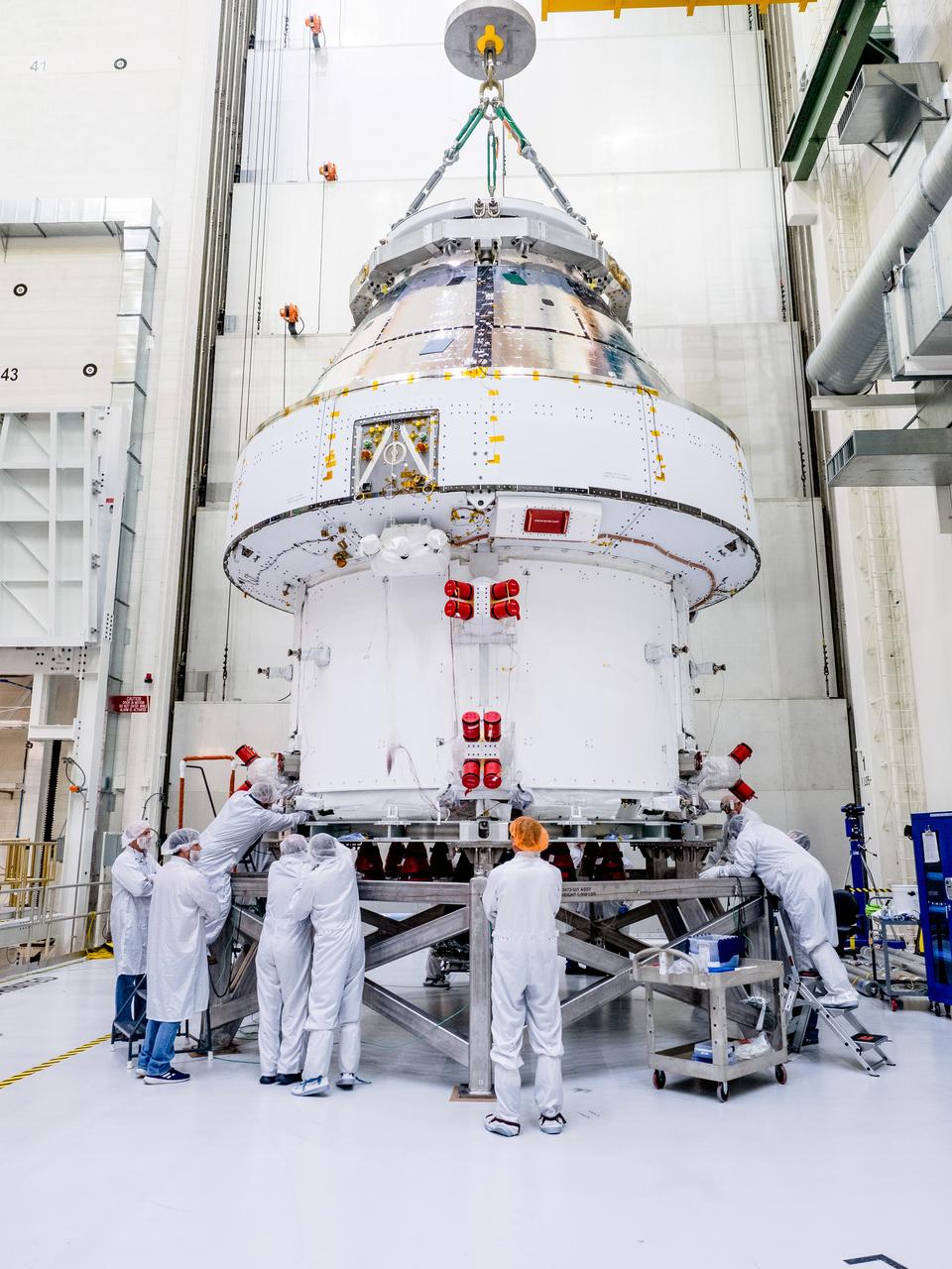
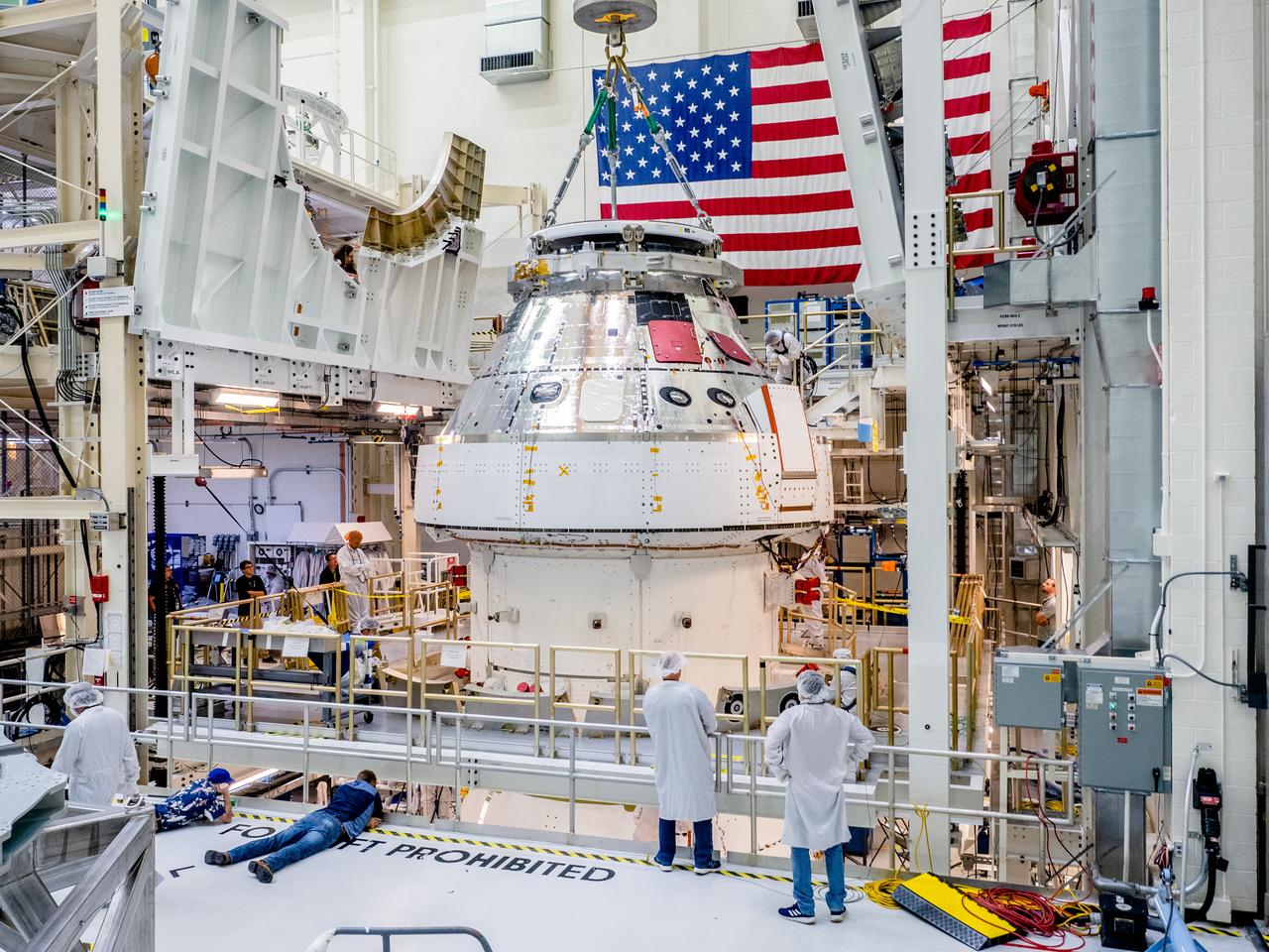
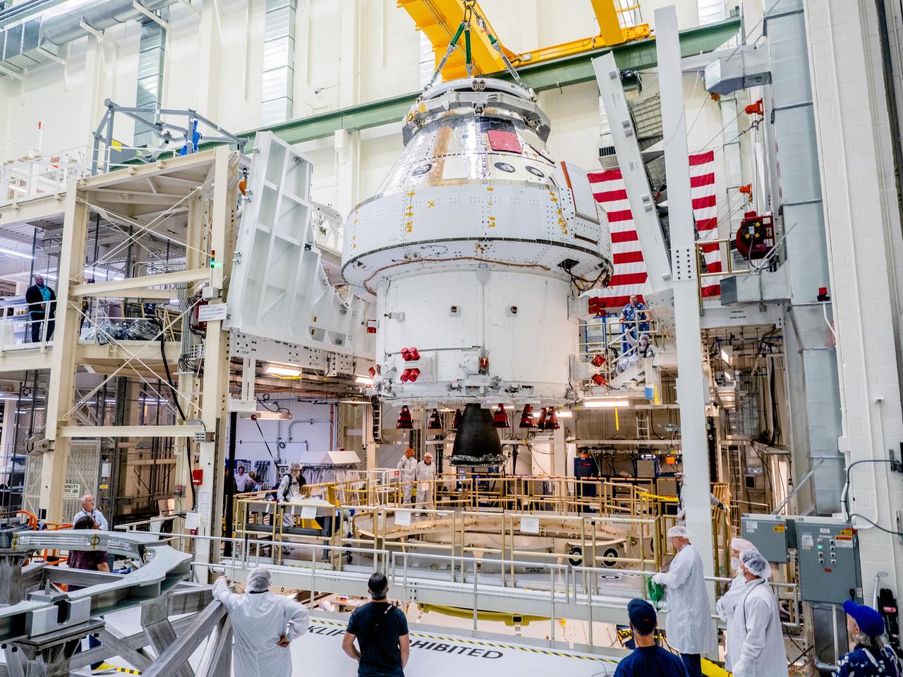
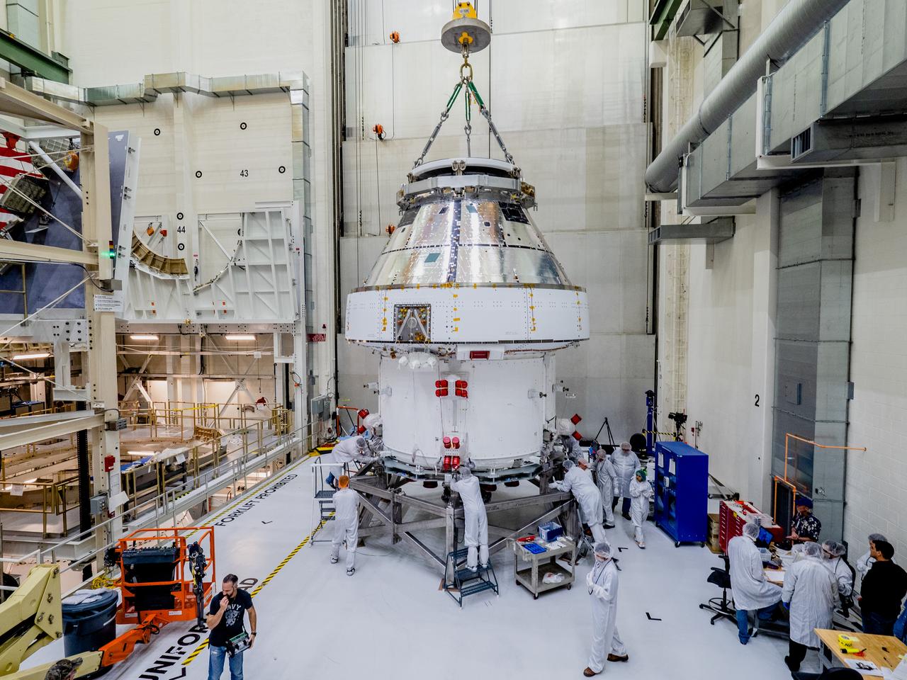
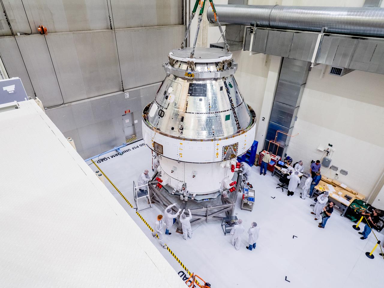
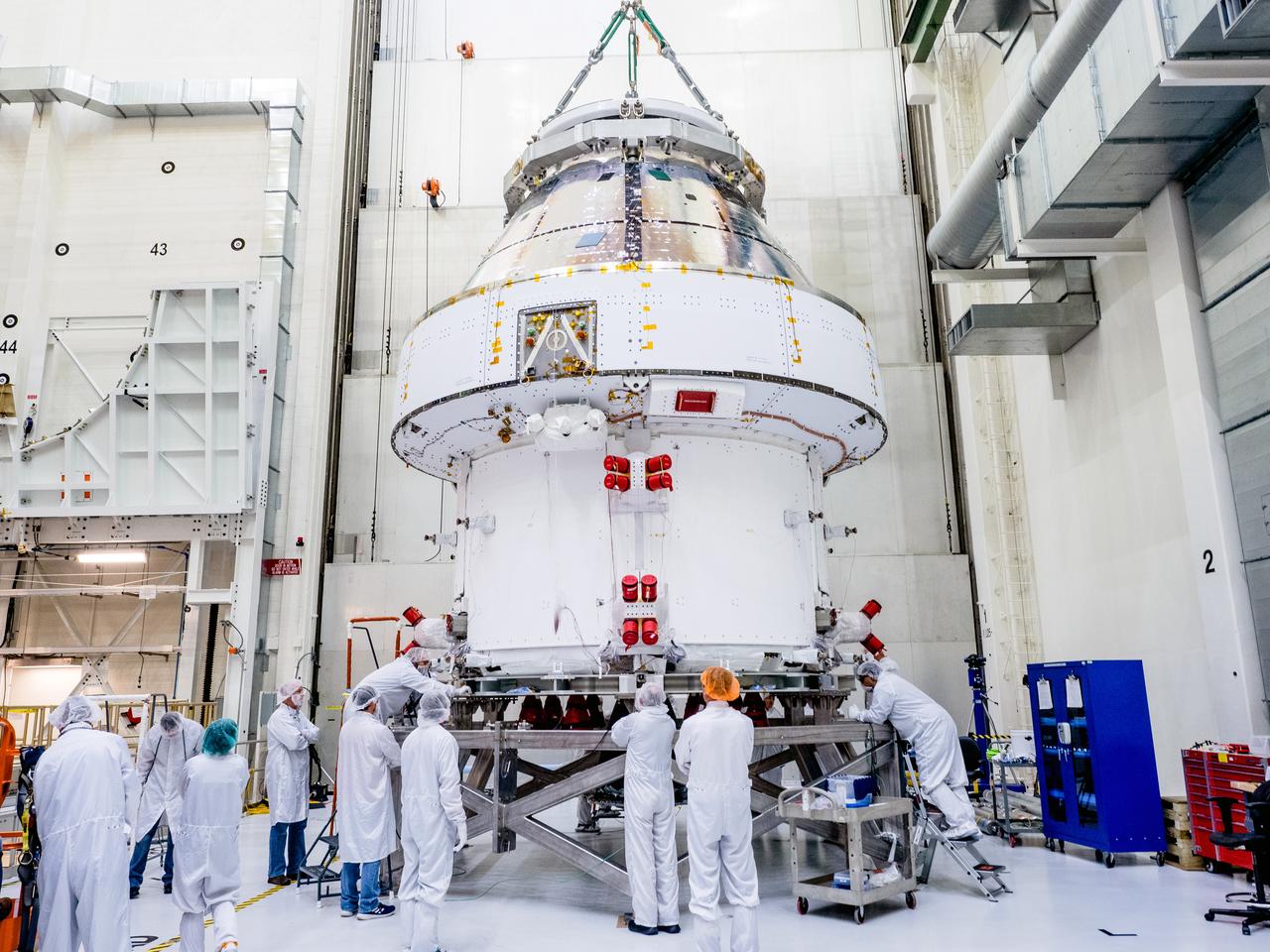
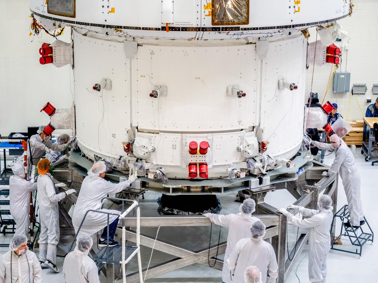
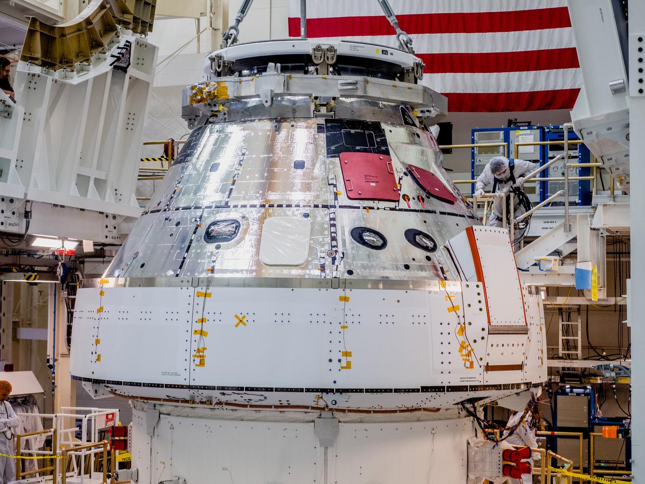
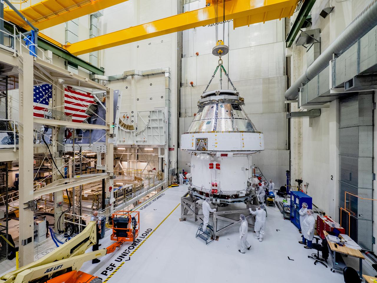
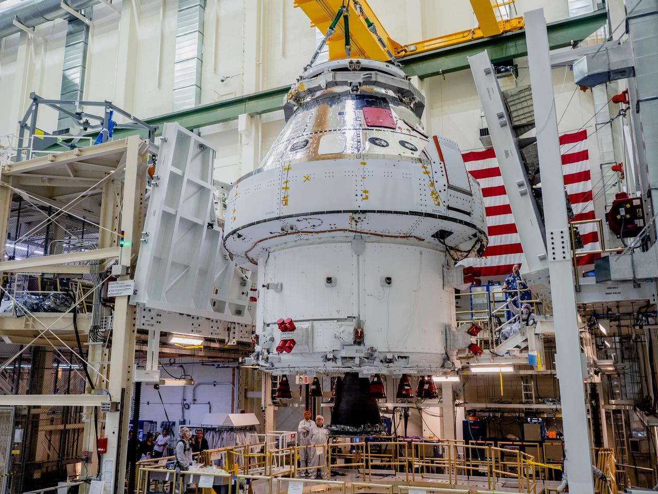
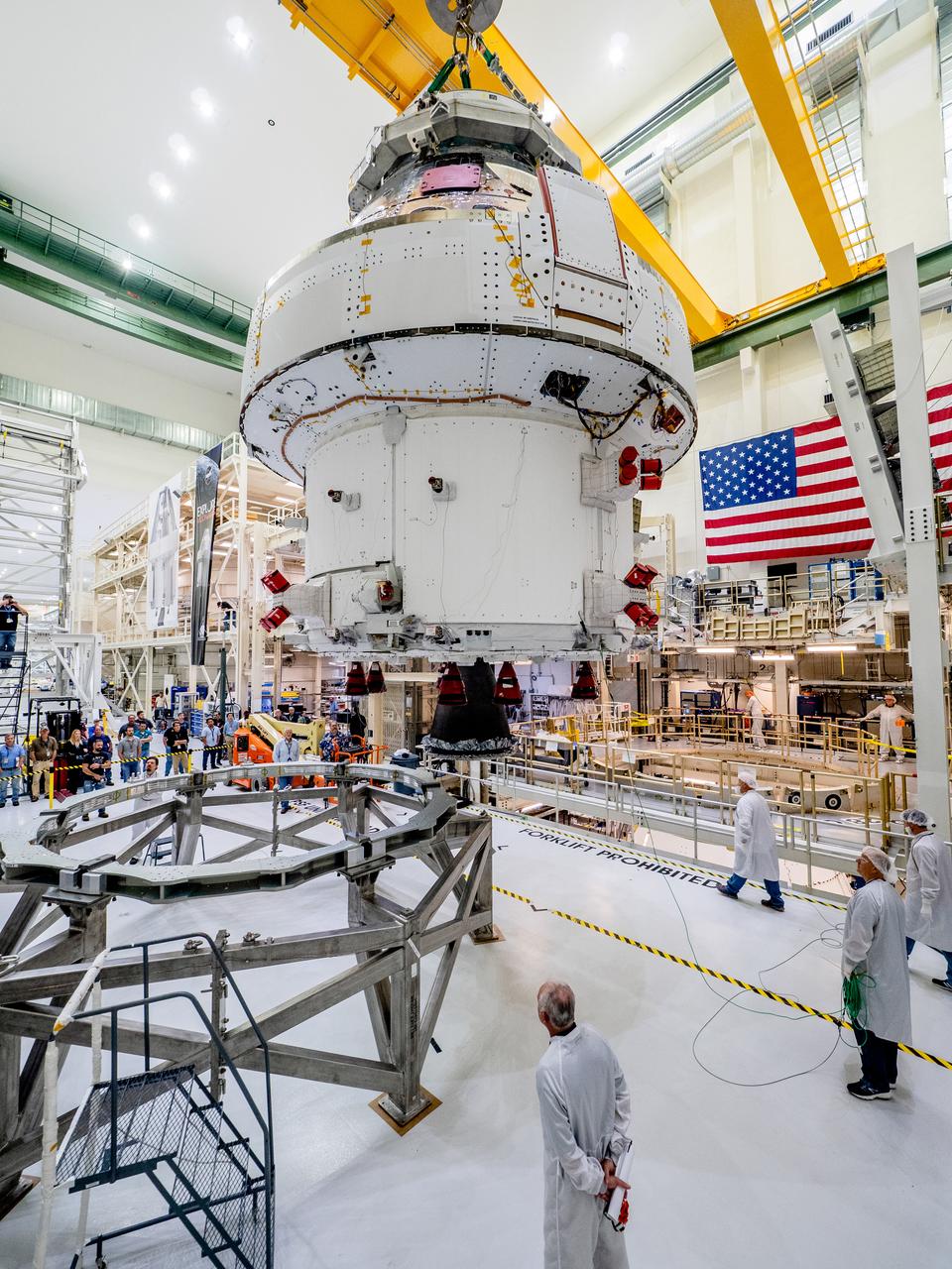
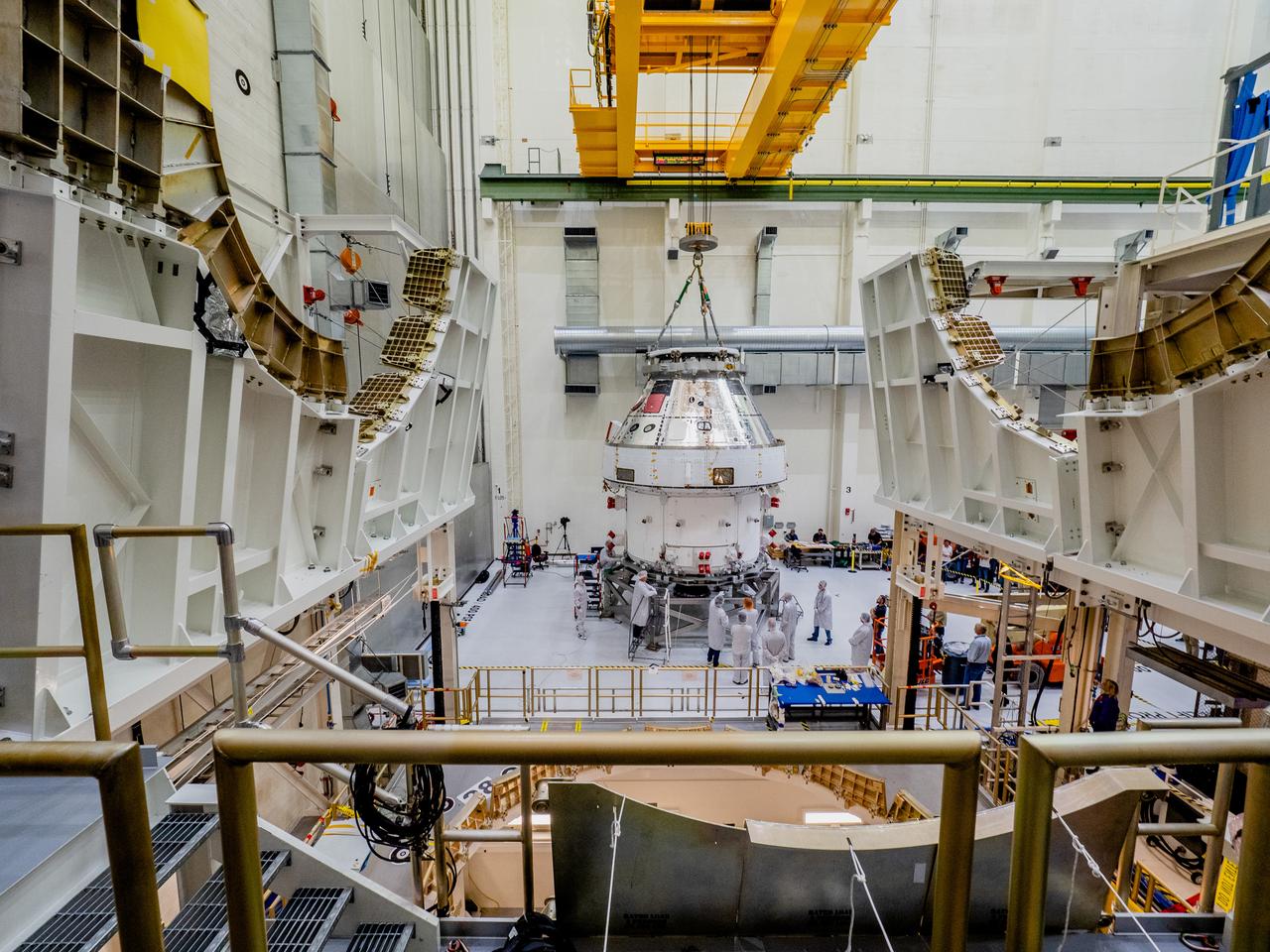
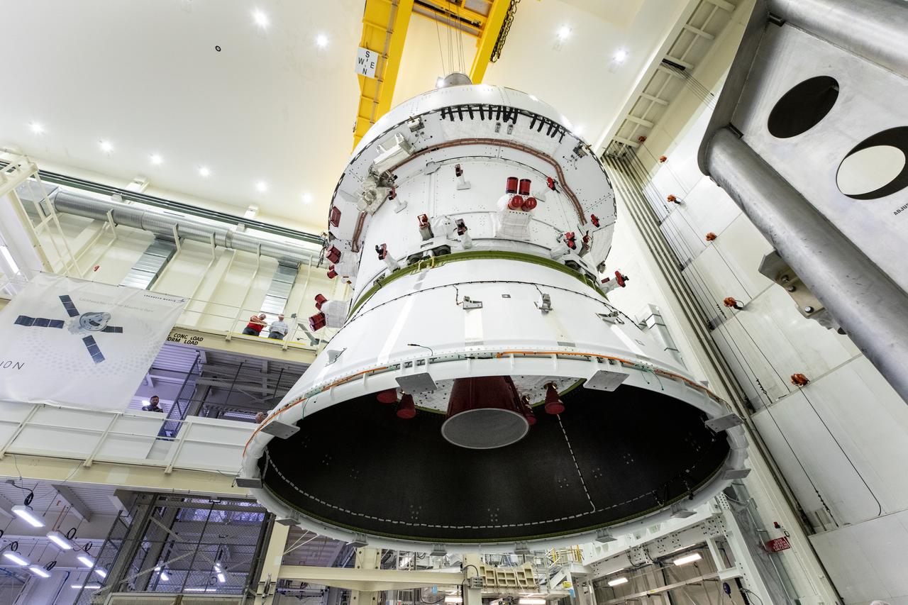
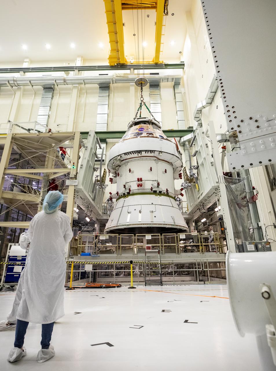
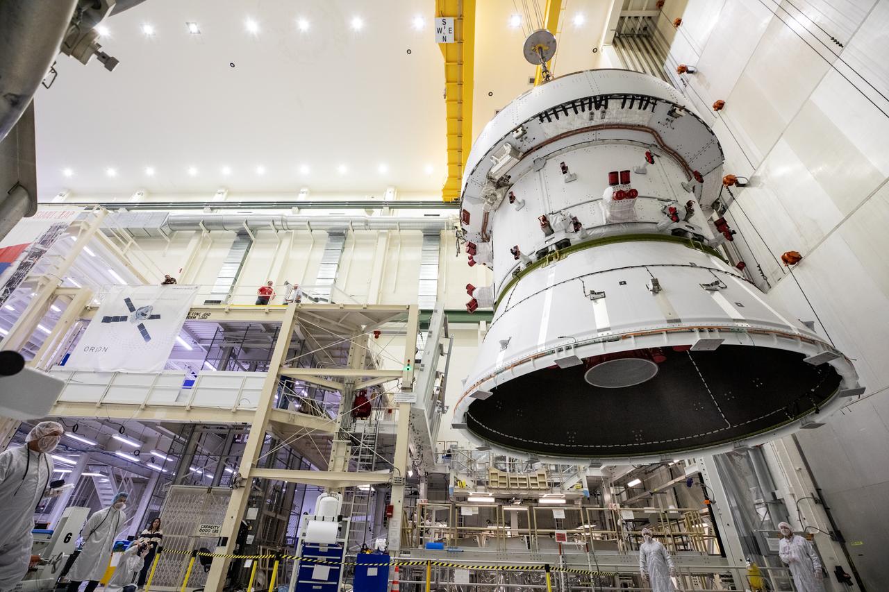
The Orion crew and service module stack for Artemis I was lifted out of the Final Assembly and Test (FAST) cell on November 11, 2019. The spacecraft has been stationed in the FAST cell since July for mating and closeout processing. The service module and crew module were moved separately into the cell, stacked and connected together for the mission. After lifting out of the cell, Orion will be attached to a tool called a verticator that rotates the stack from its vertical configuration to a horizontal configuration for transport to NASA’s Plum Brook Station in Sandusky, Ohio, where it will undergo full environmental testing to certify the complete vehicle for flight. Once the vehicle returns to Kennedy in several months, it will return to the FAST cell for installation of final panels left off for environmental testing purposes and the service module’s four solar arrays.
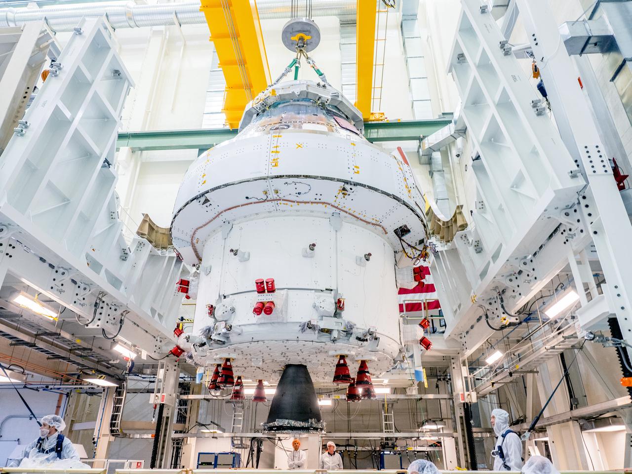
The Orion crew and service module stack for Artemis I was lifted out of the Final Assembly and Test (FAST) cell on November 11, 2019. The spacecraft has been stationed in the FAST cell since July for mating and closeout processing. The service module and crew module were moved separately into the cell, stacked and connected together for the mission. After lifting out of the cell, Orion will be attached to a tool called a verticator that rotates the stack from its vertical configuration to a horizontal configuration for transport to NASA’s Plum Brook Station in Sandusky, Ohio, where it will undergo full environmental testing to certify the complete vehicle for flight. Once the vehicle returns to Kennedy in several months, it will return to the FAST cell for installation of final panels left off for environmental testing purposes and the service module’s four solar arrays.
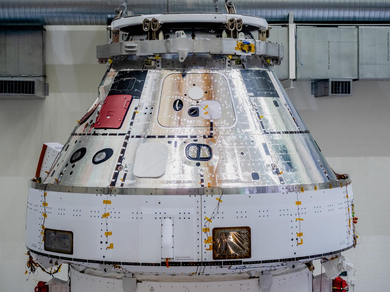
The Orion crew and service module stack for Artemis I was lifted out of the Final Assembly and Test (FAST) cell on November 11, 2019. The spacecraft has been stationed in the FAST cell since July for mating and closeout processing. The service module and crew module were moved separately into the cell, stacked and connected together for the mission. After lifting out of the cell, Orion will be attached to a tool called a verticator that rotates the stack from its vertical configuration to a horizontal configuration for transport to NASA’s Plum Brook Station in Sandusky, Ohio, where it will undergo full environmental testing to certify the complete vehicle for flight. Once the vehicle returns to Kennedy in several months, it will return to the FAST cell for installation of final panels left off for environmental testing purposes and the service module’s four solar arrays.

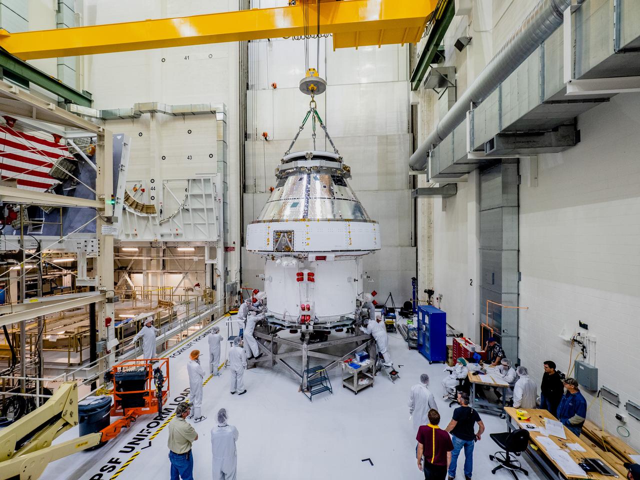
The Orion crew and service module stack for Artemis I was lifted out of the Final Assembly and Test (FAST) cell on November 11, 2019. The spacecraft has been stationed in the FAST cell since July for mating and closeout processing. The service module and crew module were moved separately into the cell, stacked and connected together for the mission. After lifting out of the cell, Orion will be attached to a tool called a verticator that rotates the stack from its vertical configuration to a horizontal configuration for transport to NASA’s Plum Brook Station in Sandusky, Ohio, where it will undergo full environmental testing to certify the complete vehicle for flight. Once the vehicle returns to Kennedy in several months, it will return to the FAST cell for installation of final panels left off for environmental testing purposes and the service module’s four solar arrays.
The Orion crew and service module stack for Artemis I was lifted out of the Final Assembly and Test (FAST) cell on November 11, 2019. The spacecraft has been stationed in the FAST cell since July for mating and closeout processing. The service module and crew module were moved separately into the cell, stacked and connected together for the mission. After lifting out of the cell, Orion will be attached to a tool called a verticator that rotates the stack from its vertical configuration to a horizontal configuration for transport to NASA’s Plum Brook Station in Sandusky, Ohio, where it will undergo full environmental testing to certify the complete vehicle for flight. Once the vehicle returns to Kennedy in several months, it will return to the FAST cell for installation of final panels left off for environmental testing purposes and the service module’s four solar arrays.
The Orion crew and service module stack for Artemis I was lifted out of the Final Assembly and Test (FAST) cell on November 11, 2019. The spacecraft has been stationed in the FAST cell since July for mating and closeout processing. The service module and crew module were moved separately into the cell, stacked and connected together for the mission. After lifting out of the cell, Orion will be attached to a tool called a verticator that rotates the stack from its vertical configuration to a horizontal configuration for transport to NASA’s Plum Brook Station in Sandusky, Ohio, where it will undergo full environmental testing to certify the complete vehicle for flight. Once the vehicle returns to Kennedy in several months, it will return to the FAST cell for installation of final panels left off for environmental testing purposes and the service module’s four solar arrays.
The Orion crew and service module stack for Artemis I was lifted out of the Final Assembly and Test (FAST) cell on November 11, 2019. The spacecraft has been stationed in the FAST cell since July for mating and closeout processing. The service module and crew module were moved separately into the cell, stacked and connected together for the mission. After lifting out of the cell, Orion will be attached to a tool called a verticator that rotates the stack from its vertical configuration to a horizontal configuration for transport to NASA’s Plum Brook Station in Sandusky, Ohio, where it will undergo full environmental testing to certify the complete vehicle for flight. Once the vehicle returns to Kennedy in several months, it will return to the FAST cell for installation of final panels left off for environmental testing purposes and the service module’s four solar arrays.
The Orion crew and service module stack for Artemis I was lifted out of the Final Assembly and Test (FAST) cell on November 11, 2019. The spacecraft has been stationed in the FAST cell since July for mating and closeout processing. The service module and crew module were moved separately into the cell, stacked and connected together for the mission. After lifting out of the cell, Orion will be attached to a tool called a verticator that rotates the stack from its vertical configuration to a horizontal configuration for transport to NASA’s Plum Brook Station in Sandusky, Ohio, where it will undergo full environmental testing to certify the complete vehicle for flight. Once the vehicle returns to Kennedy in several months, it will return to the FAST cell for installation of final panels left off for environmental testing purposes and the service module’s four solar arrays.
The Orion crew and service module stack for Artemis I was lifted out of the Final Assembly and Test (FAST) cell on November 11, 2019. The spacecraft has been stationed in the FAST cell since July for mating and closeout processing. The service module and crew module were moved separately into the cell, stacked and connected together for the mission. After lifting out of the cell, Orion will be attached to a tool called a verticator that rotates the stack from its vertical configuration to a horizontal configuration for transport to NASA’s Plum Brook Station in Sandusky, Ohio, where it will undergo full environmental testing to certify the complete vehicle for flight. Once the vehicle returns to Kennedy in several months, it will return to the FAST cell for installation of final panels left off for environmental testing purposes and the service module’s four solar arrays.
The Orion crew and service module stack for Artemis I was lifted out of the Final Assembly and Test (FAST) cell on November 11, 2019. The spacecraft has been stationed in the FAST cell since July for mating and closeout processing. The service module and crew module were moved separately into the cell, stacked and connected together for the mission. After lifting out of the cell, Orion will be attached to a tool called a verticator that rotates the stack from its vertical configuration to a horizontal configuration for transport to NASA’s Plum Brook Station in Sandusky, Ohio, where it will undergo full environmental testing to certify the complete vehicle for flight. Once the vehicle returns to Kennedy in several months, it will return to the FAST cell for installation of final panels left off for environmental testing purposes and the service module’s four solar arrays.
The Orion crew and service module stack for Artemis I was lifted out of the Final Assembly and Test (FAST) cell on November 11, 2019. The spacecraft has been stationed in the FAST cell since July for mating and closeout processing. The service module and crew module were moved separately into the cell, stacked and connected together for the mission. After lifting out of the cell, Orion will be attached to a tool called a verticator that rotates the stack from its vertical configuration to a horizontal configuration for transport to NASA’s Plum Brook Station in Sandusky, Ohio, where it will undergo full environmental testing to certify the complete vehicle for flight. Once the vehicle returns to Kennedy in several months, it will return to the FAST cell for installation of final panels left off for environmental testing purposes and the service module’s four solar arrays.

The Orion crew and service module stack for Artemis I was lifted out of the Final Assembly and Test (FAST) cell on November 11, 2019. The spacecraft has been stationed in the FAST cell since July for mating and closeout processing. The service module and crew module were moved separately into the cell, stacked and connected together for the mission. After lifting out of the cell, Orion will be attached to a tool called a verticator that rotates the stack from its vertical configuration to a horizontal configuration for transport to NASA’s Plum Brook Station in Sandusky, Ohio, where it will undergo full environmental testing to certify the complete vehicle for flight. Once the vehicle returns to Kennedy in several months, it will return to the FAST cell for installation of final panels left off for environmental testing purposes and the service module’s four solar arrays.
The Orion crew and service module stack for Artemis I was lifted out of the Final Assembly and Test (FAST) cell on November 11, 2019. The spacecraft has been stationed in the FAST cell since July for mating and closeout processing. The service module and crew module were moved separately into the cell, stacked and connected together for the mission. After lifting out of the cell, Orion will be attached to a tool called a verticator that rotates the stack from its vertical configuration to a horizontal configuration for transport to NASA’s Plum Brook Station in Sandusky, Ohio, where it will undergo full environmental testing to certify the complete vehicle for flight. Once the vehicle returns to Kennedy in several months, it will return to the FAST cell for installation of final panels left off for environmental testing purposes and the service module’s four solar arrays.
The Orion crew and service module stack for Artemis I was lifted out of the Final Assembly and Test (FAST) cell on November 11, 2019. The spacecraft has been stationed in the FAST cell since July for mating and closeout processing. The service module and crew module were moved separately into the cell, stacked and connected together for the mission. After lifting out of the cell, Orion will be attached to a tool called a verticator that rotates the stack from its vertical configuration to a horizontal configuration for transport to NASA’s Plum Brook Station in Sandusky, Ohio, where it will undergo full environmental testing to certify the complete vehicle for flight. Once the vehicle returns to Kennedy in several months, it will return to the FAST cell for installation of final panels left off for environmental testing purposes and the service module’s four solar arrays.
The Orion crew and service module stack for Artemis I was lifted out of the Final Assembly and Test (FAST) cell on November 11, 2019. The spacecraft has been stationed in the FAST cell since July for mating and closeout processing. The service module and crew module were moved separately into the cell, stacked and connected together for the mission. After lifting out of the cell, Orion will be attached to a tool called a verticator that rotates the stack from its vertical configuration to a horizontal configuration for transport to NASA’s Plum Brook Station in Sandusky, Ohio, where it will undergo full environmental testing to certify the complete vehicle for flight. Once the vehicle returns to Kennedy in several months, it will return to the FAST cell for installation of final panels left off for environmental testing purposes and the service module’s four solar arrays.
The Orion crew and service module stack for Artemis I was lifted out of the Final Assembly and Test (FAST) cell on November 11, 2019. The spacecraft has been stationed in the FAST cell since July for mating and closeout processing. The service module and crew module were moved separately into the cell, stacked and connected together for the mission. After lifting out of the cell, Orion will be attached to a tool called a verticator that rotates the stack from its vertical configuration to a horizontal configuration for transport to NASA’s Plum Brook Station in Sandusky, Ohio, where it will undergo full environmental testing to certify the complete vehicle for flight. Once the vehicle returns to Kennedy in several months, it will return to the FAST cell for installation of final panels left off for environmental testing purposes and the service module’s four solar arrays.
The Orion crew and service module stack for Artemis I was lifted out of the Final Assembly and Test (FAST) cell on November 11, 2019. The spacecraft has been stationed in the FAST cell since July for mating and closeout processing. The service module and crew module were moved separately into the cell, stacked and connected together for the mission. After lifting out of the cell, Orion will be attached to a tool called a verticator that rotates the stack from its vertical configuration to a horizontal configuration for transport to NASA’s Plum Brook Station in Sandusky, Ohio, where it will undergo full environmental testing to certify the complete vehicle for flight. Once the vehicle returns to Kennedy in several months, it will return to the FAST cell for installation of final panels left off for environmental testing purposes and the service module’s four solar arrays.
The Orion crew and service module stack for Artemis I was lifted out of the Final Assembly and Test (FAST) cell on November 11, 2019. The spacecraft has been stationed in the FAST cell since July for mating and closeout processing. The service module and crew module were moved separately into the cell, stacked and connected together for the mission. After lifting out of the cell, Orion will be attached to a tool called a verticator that rotates the stack from its vertical configuration to a horizontal configuration for transport to NASA’s Plum Brook Station in Sandusky, Ohio, where it will undergo full environmental testing to certify the complete vehicle for flight. Once the vehicle returns to Kennedy in several months, it will return to the FAST cell for installation of final panels left off for environmental testing purposes and the service module’s four solar arrays.
The Orion crew and service module stack for Artemis I was lifted out of the Final Assembly and Test (FAST) cell on November 11, 2019. The spacecraft has been stationed in the FAST cell since July for mating and closeout processing. The service module and crew module were moved separately into the cell, stacked and connected together for the mission. After lifting out of the cell, Orion will be attached to a tool called a verticator that rotates the stack from its vertical configuration to a horizontal configuration for transport to NASA’s Plum Brook Station in Sandusky, Ohio, where it will undergo full environmental testing to certify the complete vehicle for flight. Once the vehicle returns to Kennedy in several months, it will return to the FAST cell for installation of final panels left off for environmental testing purposes and the service module’s four solar arrays.
The Orion crew and service module stack for Artemis I was lifted out of the Final Assembly and Test (FAST) cell on November 11, 2019. The spacecraft has been stationed in the FAST cell since July for mating and closeout processing. The service module and crew module were moved separately into the cell, stacked and connected together for the mission. After lifting out of the cell, Orion will be attached to a tool called a verticator that rotates the stack from its vertical configuration to a horizontal configuration for transport to NASA’s Plum Brook Station in Sandusky, Ohio, where it will undergo full environmental testing to certify the complete vehicle for flight. Once the vehicle returns to Kennedy in several months, it will return to the FAST cell for installation of final panels left off for environmental testing purposes and the service module’s four solar arrays.
The Orion crew and service module stack for Artemis I was lifted out of the Final Assembly and Test (FAST) cell on November 11, 2019. The spacecraft has been stationed in the FAST cell since July for mating and closeout processing. The service module and crew module were moved separately into the cell, stacked and connected together for the mission. After lifting out of the cell, Orion will be attached to a tool called a verticator that rotates the stack from its vertical configuration to a horizontal configuration for transport to NASA’s Plum Brook Station in Sandusky, Ohio, where it will undergo full environmental testing to certify the complete vehicle for flight. Once the vehicle returns to Kennedy in several months, it will return to the FAST cell for installation of final panels left off for environmental testing purposes and the service module’s four solar arrays.
The Orion crew and service module stack for Artemis I was lifted out of the Final Assembly and Test (FAST) cell on November 11, 2019. The spacecraft has been stationed in the FAST cell since July for mating and closeout processing. The service module and crew module were moved separately into the cell, stacked and connected together for the mission. After lifting out of the cell, Orion will be attached to a tool called a verticator that rotates the stack from its vertical configuration to a horizontal configuration for transport to NASA’s Plum Brook Station in Sandusky, Ohio, where it will undergo full environmental testing to certify the complete vehicle for flight. Once the vehicle returns to Kennedy in several months, it will return to the FAST cell for installation of final panels left off for environmental testing purposes and the service module’s four solar arrays.
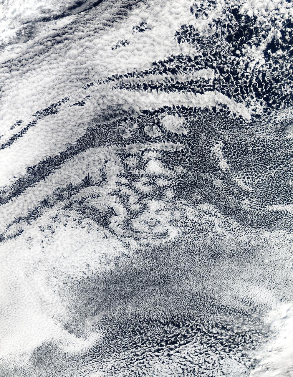
2010/107 - 04/17 at 21 :05 UTC. Open-cell and closed-cell clouds off Peru, Pacific Ocean Resembling a frosted window on a cold winter's day, this lacy pattern of marine clouds was captured off the coast of Peru in the Pacific Ocean by the MODIS on the Aqua satellite on April 19, 2010. The image reveals both open- and closed-cell cumulus cloud patterns. These cells, or parcels of air, often occur in roughly hexagonal arrays in a layer of fluid (the atmosphere often behaves like a fluid) that begins to "boil," or convect, due to heating at the base or cooling at the top of the layer. In "closed" cells warm air is rising in the center, and sinking around the edges, so clouds appear in cell centers, but evaporate around cell edges. This produces cloud formations like those that dominate the lower left. The reverse flow can also occur: air can sink in the center of the cell and rise at the edge. This process is called "open cell" convection, and clouds form at cell edges around open centers, which creates a lacy, hollow-looking pattern like the clouds in the upper right. Closed and open cell convection represent two stable atmospheric configurations — two sides of the convection coin. But what determines which path the "boiling" atmosphere will take? Apparently the process is highly chaotic, and there appears to be no way to predict whether convection will result in open or closed cells. Indeed, the atmosphere may sometimes flip between one mode and another in no predictable pattern. Satellite: Aqua NASA/GSFC/Jeff Schmaltz/MODIS Land Rapid Response Team To learn more about MODIS go to: <a href="http://rapidfire.sci.gsfc.nasa.gov/gallery/?latest" rel="nofollow">rapidfire.sci.gsfc.nasa.gov/gallery/?latest</a> <b><a href="http://www.nasa.gov/centers/goddard/home/index.html" rel="nofollow">NASA Goddard Space Flight Center</a></b> is home to the nation's largest organization of combined scientists, engineers and technologists that build spacecraft, instruments and new technology to study the Earth, the sun, our solar system, and the universe.
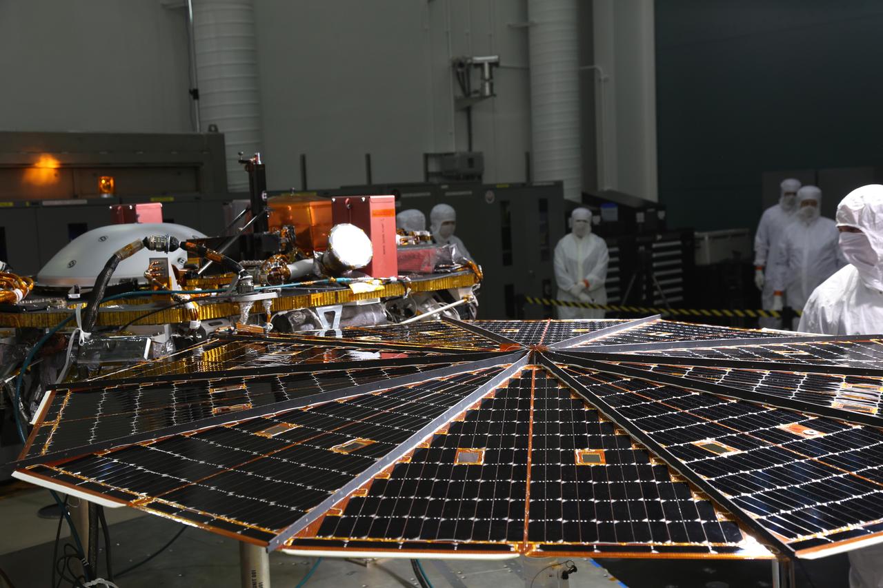
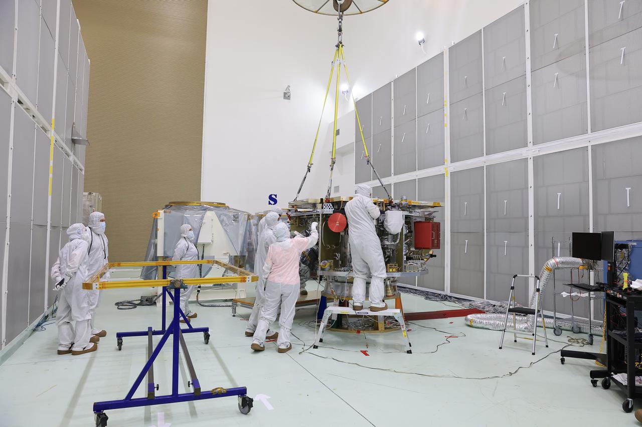
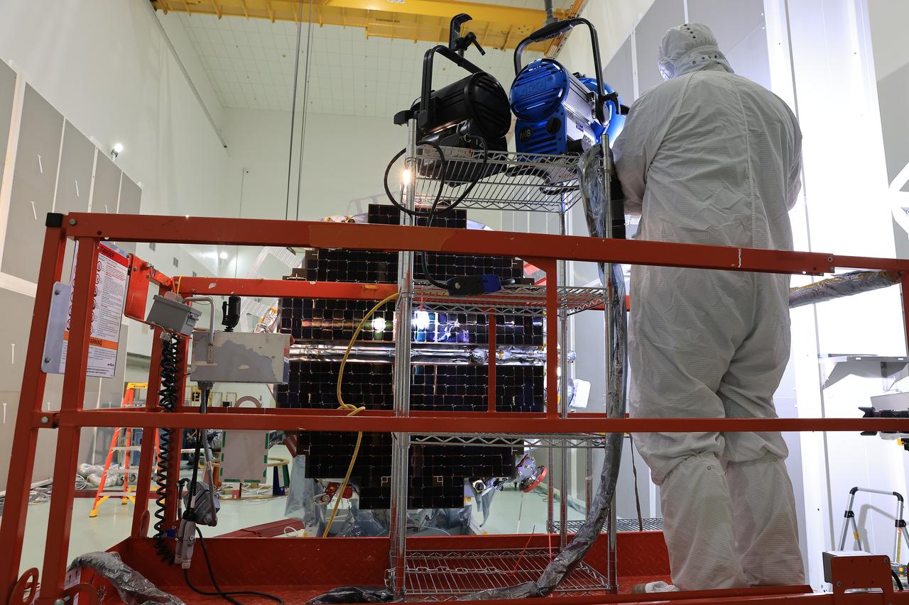
While in the landed configuration for the last time before arriving on Mars, NASA's InSight lander was commanded to deploy its solar arrays to test and verify the exact process that it will use on the surface of the Red Planet. During the test on Jan. 23, 2018 from the Lockheed Martin clean room in Littleton, Colorado, engineers and technicians evaluated that the solar arrays fully deployed and conducted an illumination test to confirm that the solar cells were collecting power. A video is available at https://photojournal.jpl.nasa.gov/catalog/PIA22203
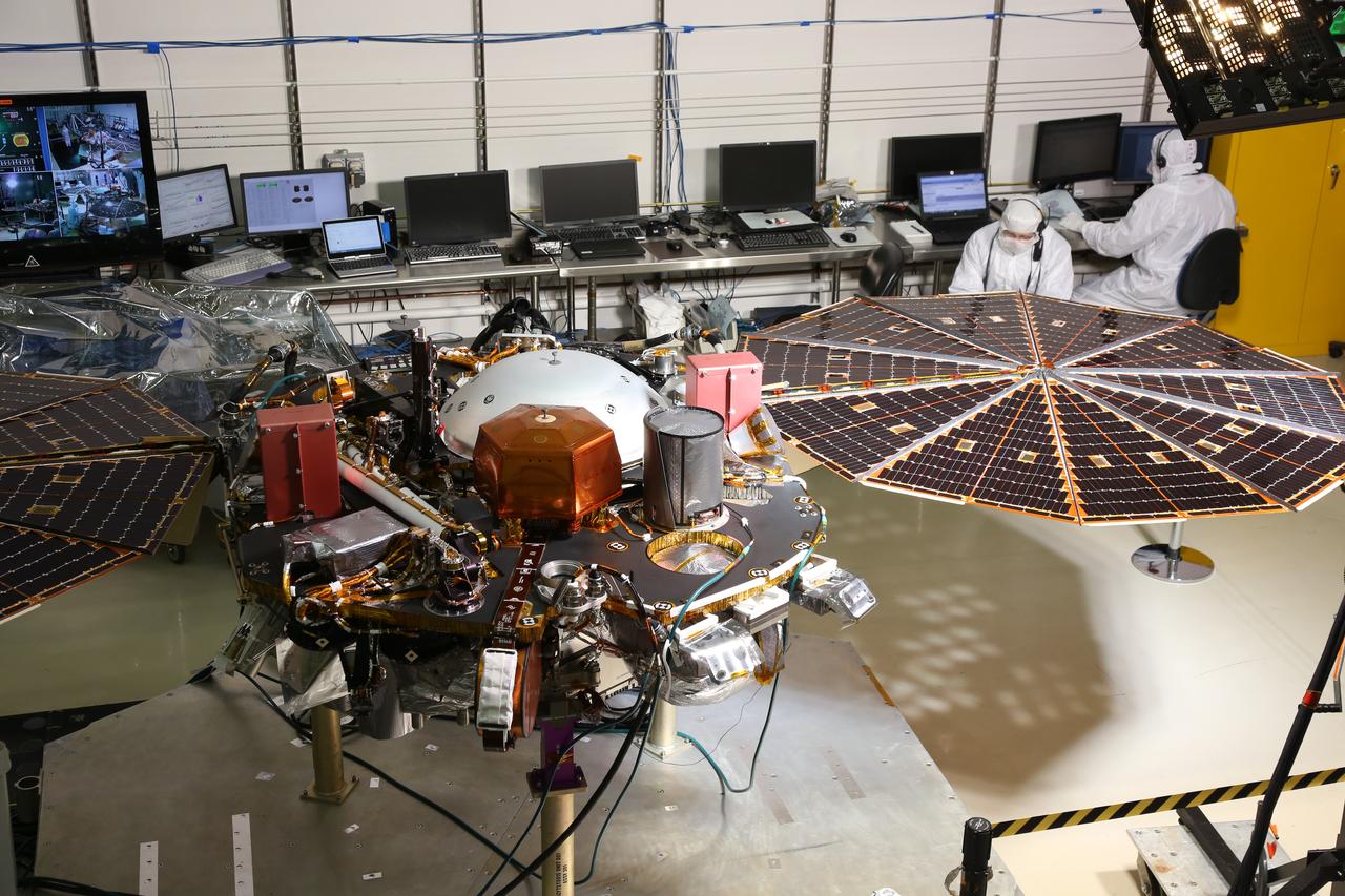
While in the landed configuration for the last time before arriving on Mars, NASA's InSight lander was commanded to deploy its solar arrays to test and verify the exact process that it will use on the surface of the Red Planet. During the test on Jan. 23, 2018 from the Lockheed Martin clean room in Littleton, Colorado, engineers and technicians evaluated that the solar arrays fully deployed and conducted an illumination test to confirm that the solar cells were collecting power. A video is available at https://photojournal.jpl.nasa.gov/catalog/PIA22202
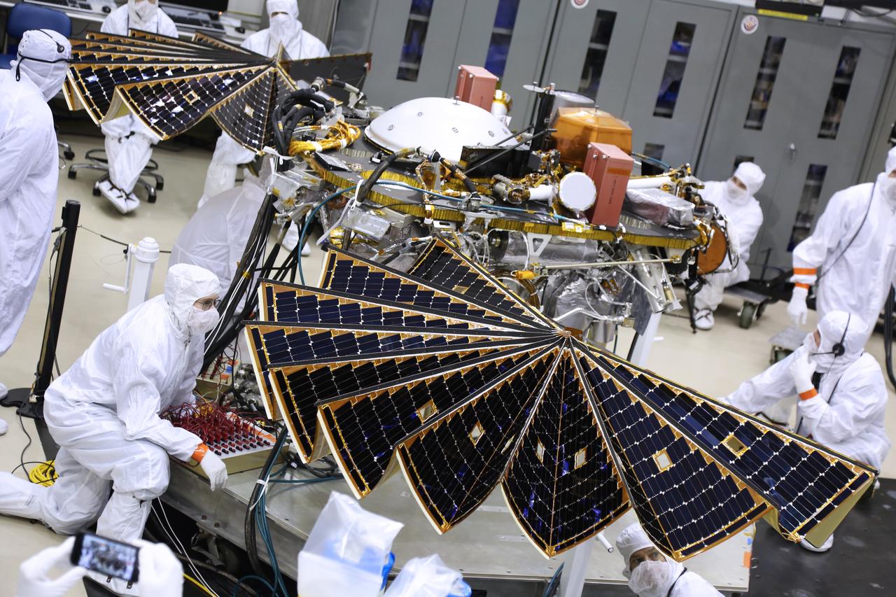
The solar arrays on NASA's InSight Mars lander were deployed as part of testing conducted Jan. 23, 2018, at Lockheed Martin Space in Littleton, Colorado. Engineers and technicians evaluated the solar arrays and performed an illumination test to confirm that the solar cells were collecting power. The launch window for InSight opens May 5, 2018. A video is available at https://photojournal.jpl.nasa.gov/catalog/PIA22205
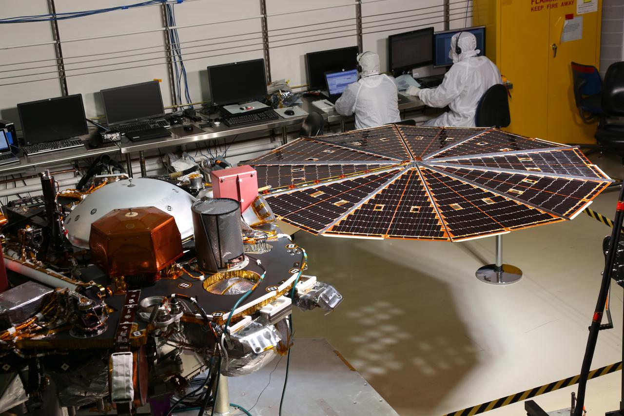
While in the landed configuration for the last time before arriving on Mars, NASA's InSight lander was commanded to deploy its solar arrays to test and verify the exact process that it will use on the surface of the Red Planet. During the test on Jan. 23, 2018 from the Lockheed Martin clean room in Littleton, Colorado, engineers and technicians evaluated that the solar arrays fully deployed and conducted an illumination test to confirm that the solar cells were collecting power. A video is available at https://photojournal.jpl.nasa.gov/catalog/PIA22201
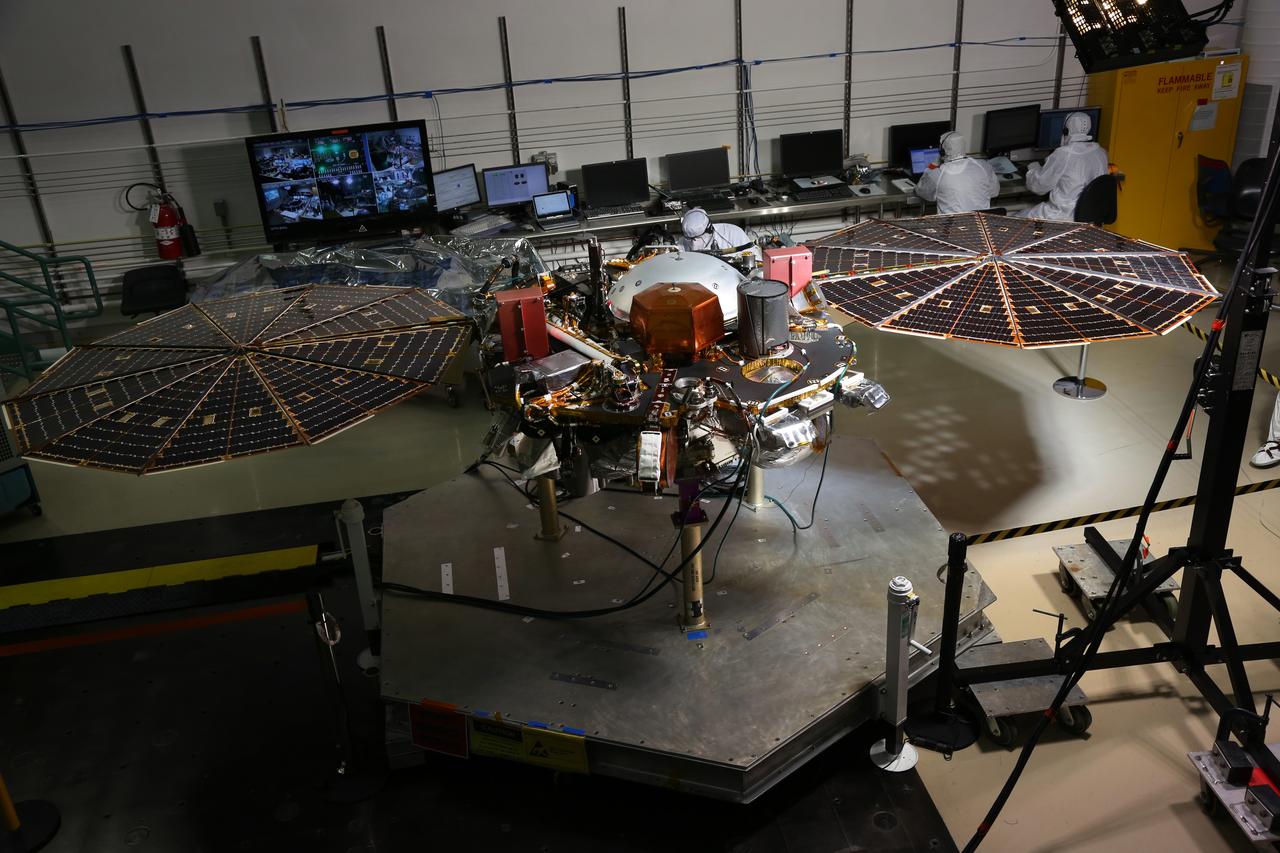
While in the landed configuration for the last time before arriving on Mars, NASA's InSight lander was commanded to deploy its solar arrays to test and verify the exact process that it will use on the surface of the Red Planet. During the test on Jan. 23, 2018 from the Lockheed Martin clean room in Littleton, Colorado, engineers and technicians evaluated that the solar arrays fully deployed and conducted an illumination test to confirm that the solar cells were collecting power. A video is available at https://photojournal.jpl.nasa.gov/catalog/PIA22200
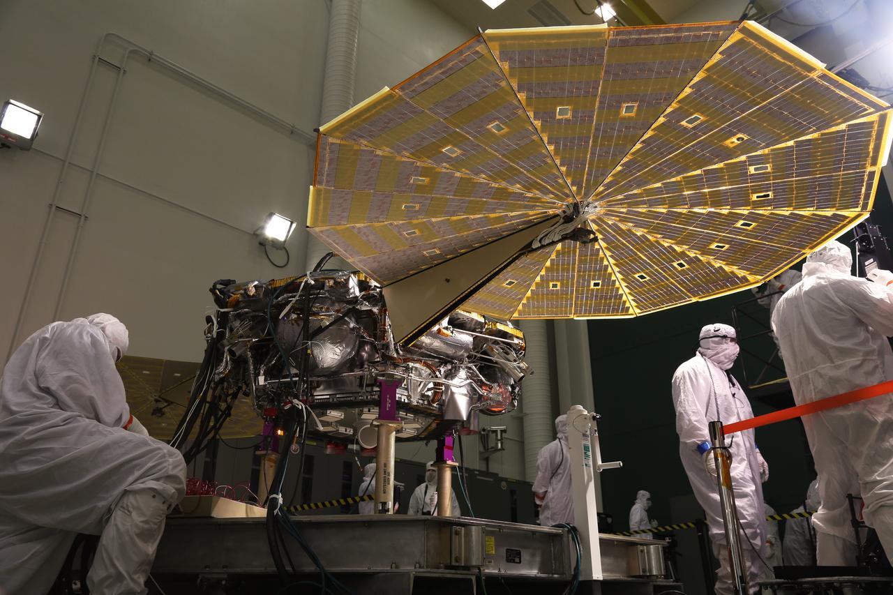
While in the landed configuration for the last time before arriving on Mars, NASA's InSight lander was commanded to deploy its solar arrays to test and verify the exact process that it will use on the surface of the Red Planet. During the test on Jan. 23, 2018 from the Lockheed Martin clean room in Littleton, Colorado, engineers and technicians evaluated that the solar arrays fully deployed and conducted an illumination test to confirm that the solar cells were collecting power. A video is available at https://photojournal.jpl.nasa.gov/catalog/PIA22204
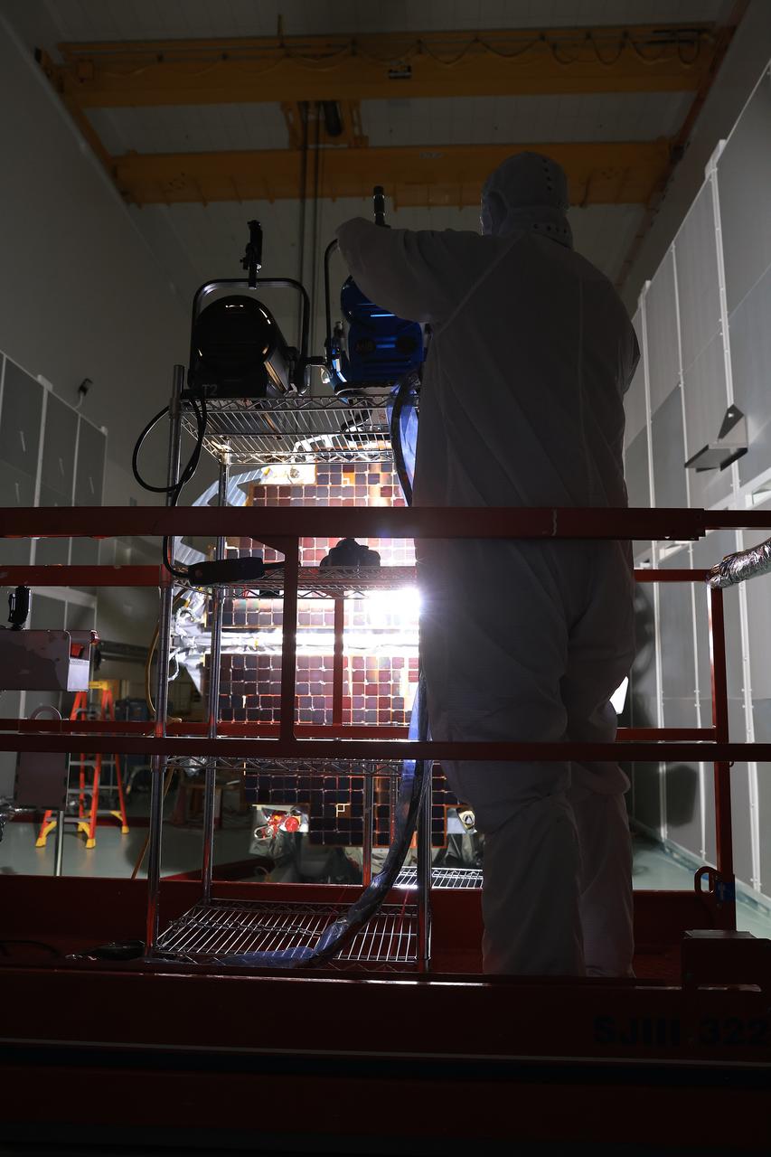
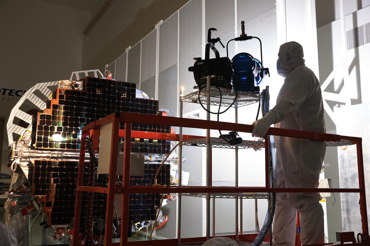
Technicians at the Astrotech Space Operations Facility near NASA’s Kennedy Space Center in Florida conduct illumination testing on Friday, July 18, 2025, by flashing a bright light that simulates the Sun into the two-panel solar array that will help power the agency’s IMAP (Interstellar Mapping and Acceleration Probe) observatory on its upcoming journey to a destination about one million miles away from Earth Lagrange Point 1. Each panel of the solar array, located on the top of IMAP, consists of 16 strings of solar cells, with 36 cells per string, and combined will convert sunlight into 500 watts of power, more than enough for the observatory, which as a system uses less power than five 100-watt incandescent light bulbs.
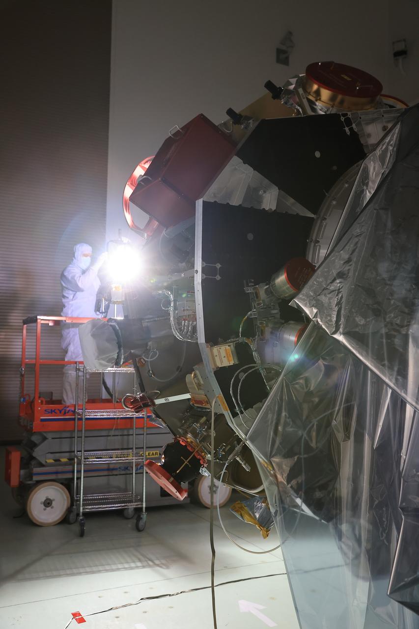
Technicians at the Astrotech Space Operations Facility near NASA’s Kennedy Space Center in Florida conduct illumination testing on Friday, July 18, 2025, by flashing a bright light that simulates the Sun into the two-panel solar array that will help power the agency’s IMAP (Interstellar Mapping and Acceleration Probe) observatory on its upcoming journey to a destination about one million miles away from Earth Lagrange Point 1. Each panel of the solar array, located on the top of IMAP, consists of 16 strings of solar cells, with 36 cells per string, and combined will convert sunlight into 500 watts of power, more than enough for the observatory, which as a system uses less power than five 100-watt incandescent light bulbs.
Technicians at the Astrotech Space Operations Facility near NASA’s Kennedy Space Center in Florida conduct illumination testing on Friday, July 18, 2025, by flashing a bright light that simulates the Sun into the two-panel solar array that will help power the agency’s IMAP (Interstellar Mapping and Acceleration Probe) observatory on its upcoming journey to a destination about one million miles away from Earth Lagrange Point 1. Each panel of the solar array, located on the top of IMAP, consists of 16 strings of solar cells, with 36 cells per string, and combined will convert sunlight into 500 watts of power, more than enough for the observatory, which as a system uses less power than five 100-watt incandescent light bulbs.
Technicians at the Astrotech Space Operations Facility near NASA’s Kennedy Space Center in Florida conduct illumination testing on Friday, July 18, 2025, by flashing a bright light that simulates the Sun into the two-panel solar array that will help power the agency’s IMAP (Interstellar Mapping and Acceleration Probe) observatory on its upcoming journey to a destination about one million miles away from Earth Lagrange Point 1. Each panel of the solar array, located on the top of IMAP, consists of 16 strings of solar cells, with 36 cells per string, and combined will convert sunlight into 500 watts of power, more than enough for the observatory, which as a system uses less power than five 100-watt incandescent light bulbs.
Technicians at the Astrotech Space Operations Facility near NASA’s Kennedy Space Center in Florida conduct illumination testing on Friday, July 18, 2025, by flashing a bright light that simulates the Sun into the two-panel solar array that will help power the agency’s IMAP (Interstellar Mapping and Acceleration Probe) observatory on its upcoming journey to a destination about one million miles away from Earth Lagrange Point 1. Each panel of the solar array, located on the top of IMAP, consists of 16 strings of solar cells, with 36 cells per string, and combined will convert sunlight into 500 watts of power, more than enough for the observatory, which as a system uses less power than five 100-watt incandescent light bulbs.
Technicians at the Astrotech Space Operations Facility near NASA’s Kennedy Space Center in Florida conduct illumination testing on Friday, July 18, 2025, by flashing a bright light that simulates the Sun into the two-panel solar array that will help power the agency’s IMAP (Interstellar Mapping and Acceleration Probe) observatory on its upcoming journey to a destination about one million miles away from Earth Lagrange Point 1. Each panel of the solar array, located on the top of IMAP, consists of 16 strings of solar cells, with 36 cells per string, and combined will convert sunlight into 500 watts of power, more than enough for the observatory, which as a system uses less power than five 100-watt incandescent light bulbs.
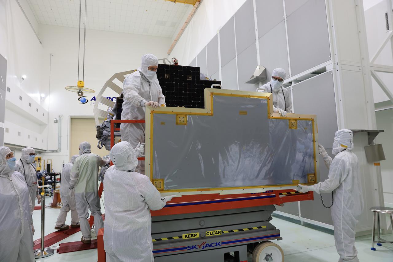
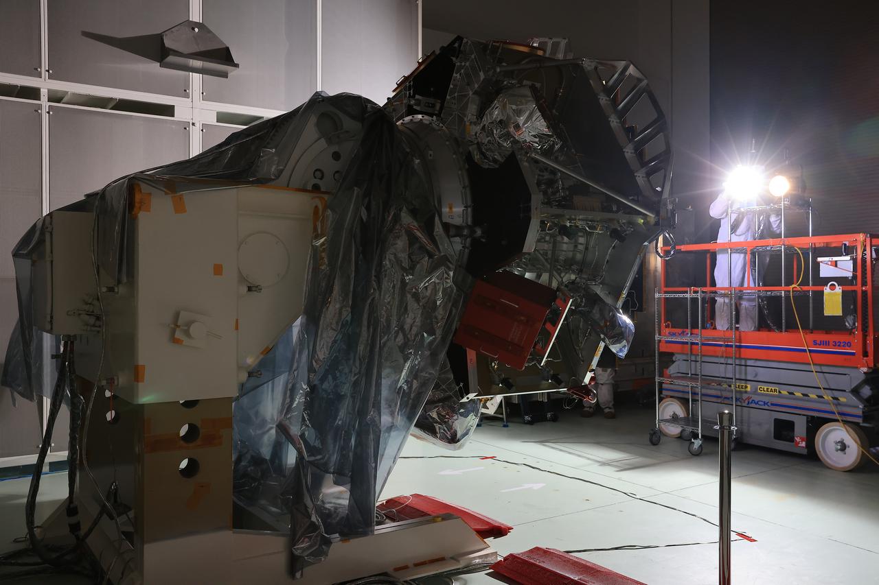
Technicians at the Astrotech Space Operations Facility near NASA’s Kennedy Space Center in Florida remove a protective covering from the two-panel solar array on Friday, July 18, 2025, that will help power the agency’s IMAP (Interstellar Mapping and Acceleration Probe) observatory on its upcoming journey to a destination about one million miles away from Earth at Lagrange Point 1. Each panel of the solar array, located on the top of IMAP, consists of 16 strings of solar cells, with 36 cells per string, and combined will convert sunlight into 500 watts of power, more than enough for the observatory, which as a system uses less power than five 100-watt incandescent light bulbs.

Technicians at the Astrotech Space Operations Facility near NASA’s Kennedy Space Center in Florida conduct illumination testing on Friday, July 18, 2025, by flashing a bright light that simulates the Sun into the two-panel solar array that will help power the agency’s IMAP (Interstellar Mapping and Acceleration Probe) observatory on its upcoming journey to a destination about one million miles away from Earth Lagrange Point 1. Each panel of the solar array, located on the top of IMAP, consists of 16 strings of solar cells, with 36 cells per string, and combined will convert sunlight into 500 watts of power, more than enough for the observatory, which as a system uses less power than five 100-watt incandescent light bulbs.
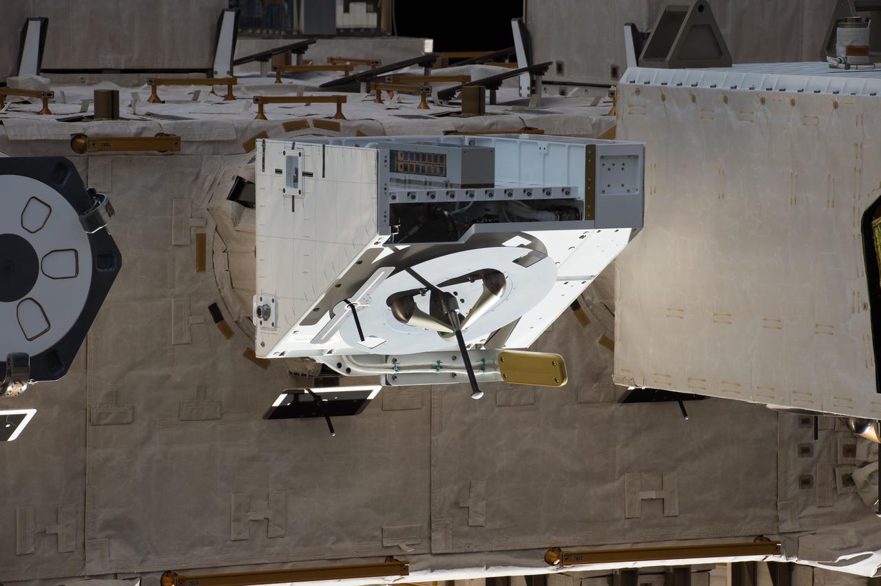
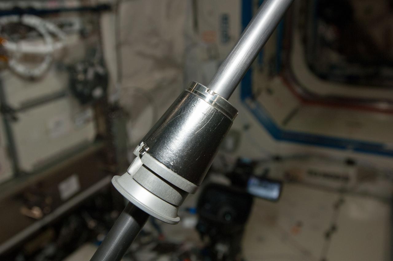
iss048e050816 (8/5/2016) --- A view of the NanoRacks External Platform (NREP), containing the NanoRacks-Gumstix and NanoRacks NanoTube Solar Cell payloads, installed on the JEM (Japanese Experiment Module) Exposed Facility (JEF). The NanoRacks External Platform is a compact research platform fitted for versatile use on the exterior of the International Space Station (ISS).
This is a view of a solar cell blanket deployed on a water table during the Solar Array deployment test. The Hubble Space Telescope (HST) Solar Arrays provide power to the spacecraft. The arrays are mounted on opposite sides of the HST, on the forward shell of the Support Systems Module. Each array stands on a 4-foot mast that supports a retractable wing of solar panels 40-feet (12.1-meters) long and 8.2-feet (2.5-meters) wide, in full extension. The arrays rotate so that the solar cells face the Sun as much as possible to harness the Sun's energy. The Space Telescope Operations Control Center at the Goddard Space Center operates the array, extending the panels and maneuvering the spacecraft to focus maximum sunlight on the arrays. The purpose of the HST, the most complex and sensitive optical telescope ever made, is to study the cosmos from a low-Earth orbit. By placing the telescope in space, astronomers are able to collect data that is free of the Earth's atmosphere. The HST Solar Array was designed by the European Space Agency and built by British Aerospace. The Marshall Space Flight Center had overall responsibility for design, development, and construction of the HST.
The Pathfinder research aircraft's solar cell arrays are prominently displayed as it touches down on the bed of Rogers Dry Lake at the Dryden Flight Research Center, Edwards, California, following a test flight. The solar arrays covered more than 75 percent of Pathfinder's upper wing surface, and provided electricity to power its six electric motors, flight controls, communications links and a host of scientific sensors.
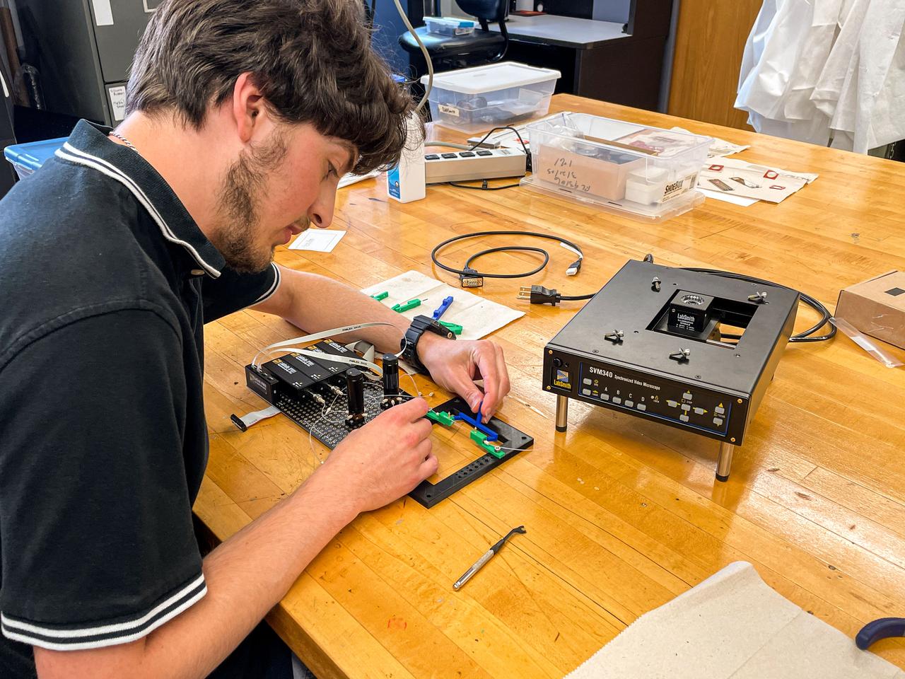
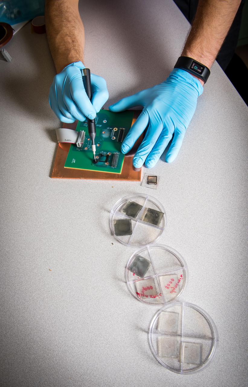
jsc2024e016254 (7/30/2021) --- A capstone student assembles the microscope and fluid breadboard for the Nano Particle Haloing Suspension payload. This payload tests controlled assembly of nanoparticles in a solution of zirconia and titanium-dioxide coated silica. Effective demonstration could lead to applications in an enhanced solar cell generation technology known as quantum-dot solar synthesis. Image courtesy of the University of Louisville.
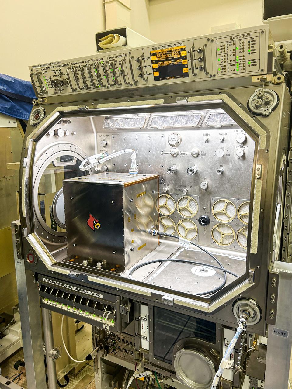
jsc2024e016253 (1/8/2024) --- The Nano Particle Haloing Suspension payload undergoes a fitting test at NASA's Marshall Space Flight Center in the Microgravity Science Glovebox replica. This payload tests controlled assembly of nanoparticles in a solution of zirconia and titanium-dioxide coated silica. Effective demonstration could lead to applications in an enhanced solar cell generation technology known as quantum-dot solar synthesis. Image courtesy of the University of Louisville.
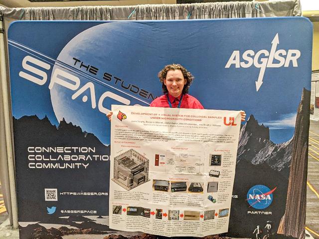
jsc2024e016255 (2/6/2024) --- Justin Murphy is an undergraduate Mechanical Engineering student (graduated May 2023) who has worked on the “Nano Halo” project and gave a poster presentation of his payload at ASGSR 2022 in Houston, Texas. The Nano Particle Haloing Suspension project tests controlled assembly of nanoparticles that could have applications in an enhanced solar cell generation technology known as quantum-dot solar synthesis. Image courtesy of the University of Louisville.
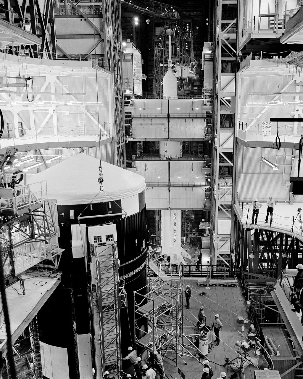
CAPE KENNEDY, Fla. -- At the Kennedy Space Center in Florida, one of Skylab 1's solar cell arrays is installed on the orbital space station in High Bay 2 of the Vehicle Assembly Building. Skylab 2 launch vehicle is in high bay 1, visible in the background. Each of the two solar cell arrays on the space station that will be deployed in orbit is designed to provide 10,500 watts of power. All power needed to operate the station and the Apollo Telescope mount will be taken from the arrays. Each array will have almost 1,177 square feet of surface area to turn sunlight into electrical power. Skylab 1 is schedule for launch April 30, 1973 and Skylab 2, carrying the astronauts Charles Conrad Jr., Dr. Joseph P. Kerwin and Paul J. Weitz to dock with the space station and enter it to live and work for 28 days, will be launched a day later. Photo Credit: NASA
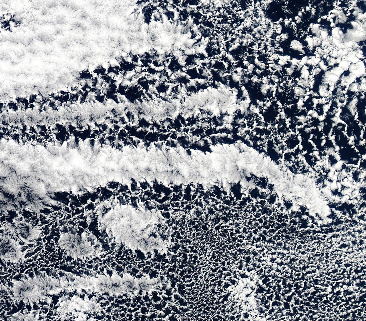
2010/107 - 04/17 at 21 :05 UTC. Open-cell and closed-cell clouds off Peru, Pacific Ocean. To view the full fame of this image to go: <a href="http://www.flickr.com/photos/gsfc/4557497219/">www.flickr.com/photos/gsfc/4557497219/</a> Resembling a frosted window on a cold winter's day, this lacy pattern of marine clouds was captured off the coast of Peru in the Pacific Ocean by the MODIS on the Aqua satellite on April 19, 2010. The image reveals both open- and closed-cell cumulus cloud patterns. These cells, or parcels of air, often occur in roughly hexagonal arrays in a layer of fluid (the atmosphere often behaves like a fluid) that begins to "boil," or convect, due to heating at the base or cooling at the top of the layer. In "closed" cells warm air is rising in the center, and sinking around the edges, so clouds appear in cell centers, but evaporate around cell edges. This produces cloud formations like those that dominate the lower left. The reverse flow can also occur: air can sink in the center of the cell and rise at the edge. This process is called "open cell" convection, and clouds form at cell edges around open centers, which creates a lacy, hollow-looking pattern like the clouds in the upper right. Closed and open cell convection represent two stable atmospheric configurations — two sides of the convection coin. But what determines which path the "boiling" atmosphere will take? Apparently the process is highly chaotic, and there appears to be no way to predict whether convection will result in open or closed cells. Indeed, the atmosphere may sometimes flip between one mode and another in no predictable pattern. Satellite: Aqua NASA/GSFC/Jeff Schmaltz/MODIS Land Rapid Response Team To learn more about MODIS go to: <a href="http://rapidfire.sci.gsfc.nasa.gov/gallery/?latest" rel="nofollow">rapidfire.sci.gsfc.nasa.gov/gallery/?latest</a> <b><a href="http://www.nasa.gov/centers/goddard/home/index.html" rel="nofollow">NASA Goddard Space Flight Center</a></b> is home to the nation's largest organization of combined scientists, engineers and technologists that build spacecraft, instruments and new technology to study the Earth, the sun, our solar system, and the universe.
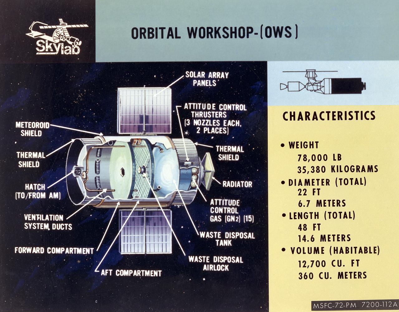
This cutaway illustration shows the characteristics and basic elements of the Skylab Orbiter Workshop (OWS). The OWS was divided into two major compartments. The lower level provided crew accommodations for sleeping, food preparation and consumption, hygiene, waste processing and disposal, and performance of certain experiments. The upper level consisted of a large work area and housed water storage tanks, a food freezer, storage vaults for film, scientific airlocks, mobility and stability experiment equipment, and other experimental equipment. The compartment below the crew quarters was a container for liquid and solid waste and trash accumulated throughout the mission. A solar array, consisting of two wings covered on one side with solar cells, was mounted outside the workshop to generate electrical power to augment the power generated by another solar array mounted on the solar observatory. Thrusters were provided at one end of the workshop for short-term control of the attitude of the space station.
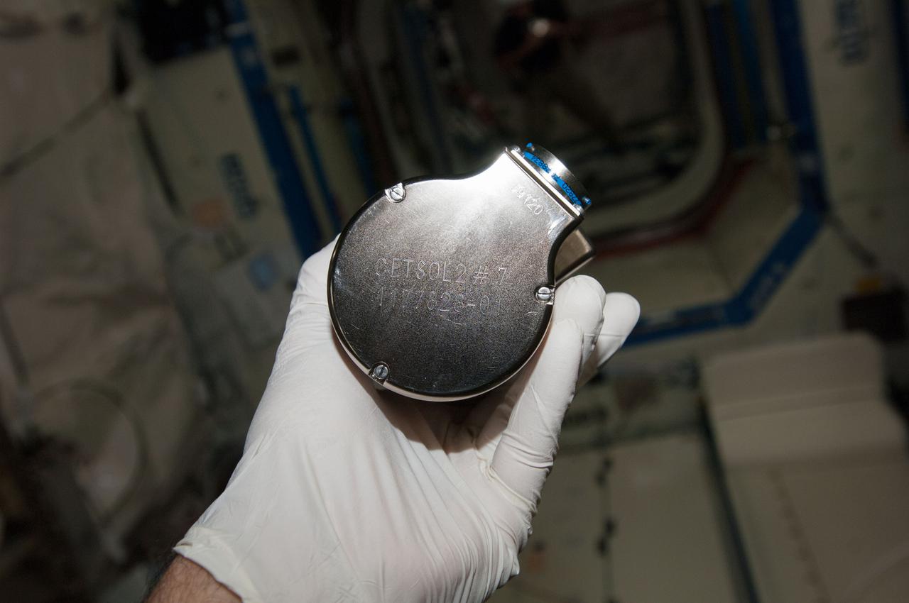
iss038e045758 (2/12/2014) --- A view of Columnar-to-Equiaxed Transition in Solidification Processing-2 (CETSOL-2) test sample 7 which is to be installed into the Material Science Laboratory (MSL) Solidification and Quench Furnace (SQF). This investigation aims to deepen the understanding of the physical principles that govern solidification processes in metal alloys. The patterns of the crystals resulting from transitions of liquids to solids is important for processes used to produce materials such as solar cells, thermoelectrics, and metal alloys.
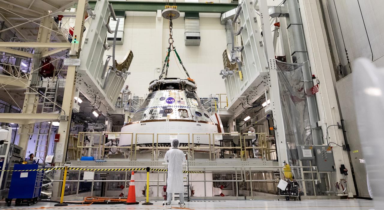
Technicians with NASA and Lockheed Martin operate a 30-ton crane to move NASA’s Artemis II Orion spacecraft out of the Final Assembly and System Testing cell inside the Neil A. Operations and Checkout Building at NASA’s Kennedy Space Center in Florida on Saturday, Feb. 22, 2025. The move prepares for the upcoming installation of four solar array wings and spacecraft adapter jettison fairings for the agency’s first crewed flight test under the Artemis campaign.
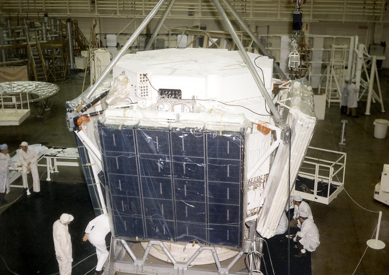
The Apollo Telescope Mount (ATM) was designed and developed by the Marshall Space Flight Center and served as the primary scientific instrument unit aboard Skylab (1973-1979). The ATM consisted of eight scientific instruments as well as a number of smaller experiments. In this image, the set of four large solar cell arrays, which could produce up to as much as 1.1 kilowatts of electric power, are being installed on an ATM prototype.
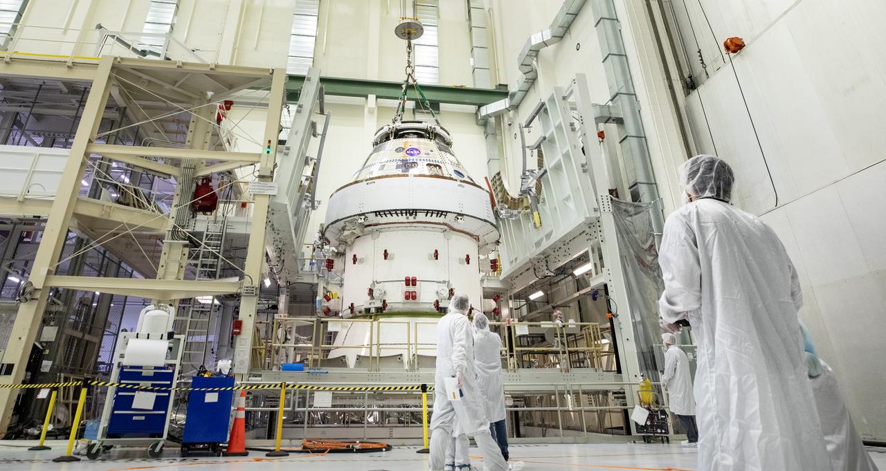
Technicians with NASA and Lockheed Martin operate a 30-ton crane to move NASA’s Artemis II Orion spacecraft out of the Final Assembly and System Testing cell inside the Neil A. Operations and Checkout Building at NASA’s Kennedy Space Center in Florida on Saturday, Feb. 22, 2025. The move prepares for the upcoming installation of four solar array wings and spacecraft adapter jettison fairings for the agency’s first crewed flight test under the Artemis campaign.
iss038e045760 92/12/2014) --- A view of Columnar-to-Equiaxed Transition in Solidification Processing-2 (CETSOL-2) test sample 7 which is to be installed into the Material Science Laboratory (MSL) Solidification and Quench Furnace (SQF). This investigation aims to deepen the understanding of the physical principles that govern solidification processes in metal alloys. The patterns of the crystals resulting from transitions of liquids to solids is important for processes used to produce materials such as solar cells, thermoelectrics, and metal alloys.

Technicians with NASA and Lockheed Martin operate a 30-ton crane to move NASA’s Artemis II Orion spacecraft out of the Final Assembly and System Testing cell inside the Neil A. Operations and Checkout Building at NASA’s Kennedy Space Center in Florida on Saturday, Feb. 22, 2025. The move prepares for the upcoming installation of four solar array wings and spacecraft adapter jettison fairings for the agency’s first crewed flight test under the Artemis campaign.
Technicians with NASA and Lockheed Martin operate a 30-ton crane to move NASA’s Artemis II Orion spacecraft out of the Final Assembly and System Testing cell inside the Neil A. Operations and Checkout Building at NASA’s Kennedy Space Center in Florida on Saturday, Feb. 22, 2025. The move prepares for the upcoming installation of four solar array wings and spacecraft adapter jettison fairings for the agency’s first crewed flight test under the Artemis campaign.
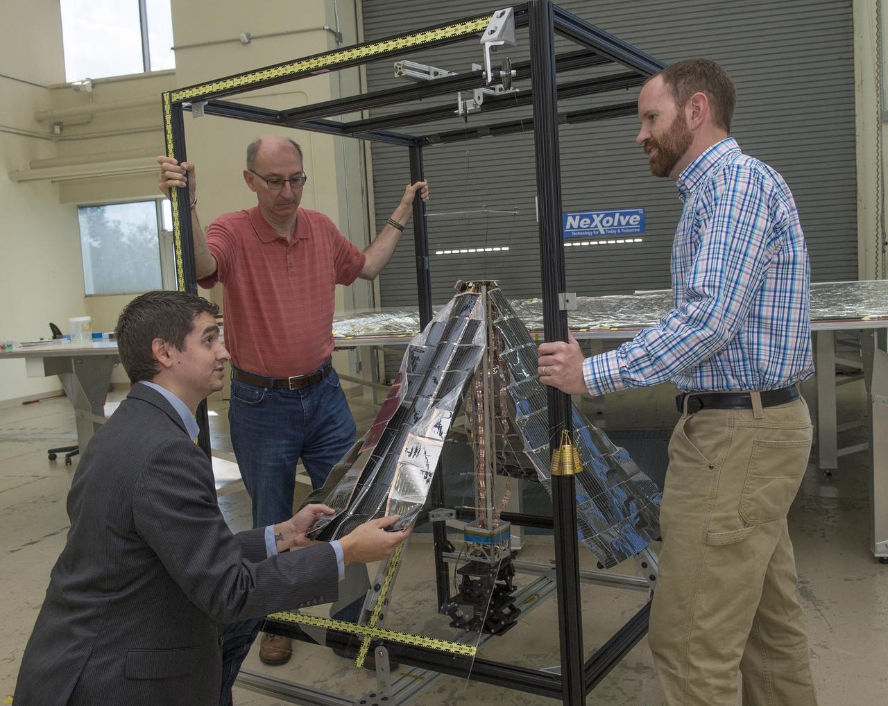
JOHN CARR, CO-PRINCIPAL INVESTIGATOR FOR NASA'S LIGHTWEIGHT INTEGRATED SOLAR ARRAY AND TRANSCEIVER PROJECT, KNEELS TO SHOW HOW ONE OF THE THIN-FILM SIDES OR "PETALS" IN WHICH PHOTO-VOLTAIC CELLS ARE EMBEDDED, IS FOLDED AND STOWED BEFORE LAUNCH. LOOKING ON DURING A DEMONSTRATION AFTER TESTING AT NEXOLVE, ARE LES JOHNSON, LEFT, ALSO CO-PRINCIPAL INVESTIGATOR, AND DARREN BOYD, RIGHT, THE RADIO FREQUENCY LEAD FOR THE PROJECT.
Technicians with NASA and Lockheed Martin operate a 30-ton crane to move NASA’s Artemis II Orion spacecraft out of the Final Assembly and System Testing cell inside the Neil A. Operations and Checkout Building at NASA’s Kennedy Space Center in Florida on Saturday, Feb. 22, 2025. The move prepares for the upcoming installation of four solar array wings and spacecraft adapter jettison fairings for the agency’s first crewed flight test under the Artemis campaign.
Technicians with NASA and Lockheed Martin operate a 30-ton crane to move NASA’s Artemis II Orion spacecraft out of the Final Assembly and System Testing cell inside the Neil A. Operations and Checkout Building at NASA’s Kennedy Space Center in Florida on Saturday, Feb. 22, 2025. The move prepares for the upcoming installation of four solar array wings and spacecraft adapter jettison fairings for the agency’s first crewed flight test under the Artemis campaign.
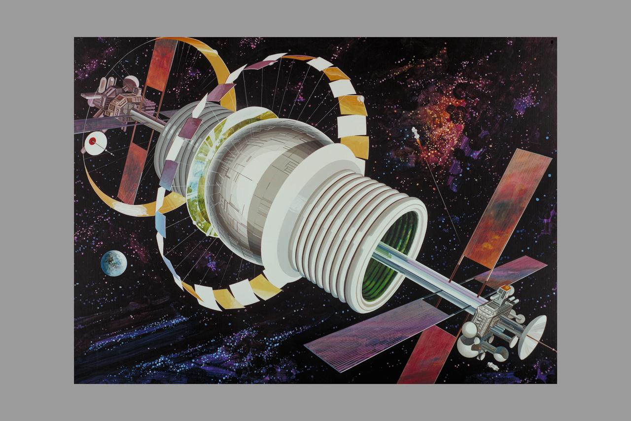
Artist: Rick Guidice Space Colonization - Bernal Sphere - The residential area is in the central sphere. Farming regions are in the 'tires.' Mirrors reflect sunlight into the habitat and farms. The large flat panels radiate away extra heat into space, and panels of solar cells provide electricity. Factories and docks for spaceships are at either end of the long central tube. (NOTE: art printed in Book 'Space Colony - Frontier of the 21st Century by Franklyn M. Branley)