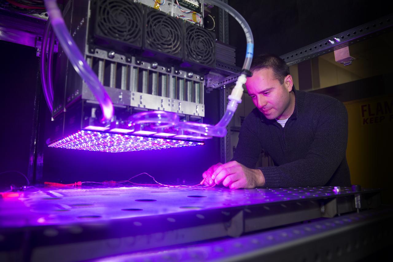
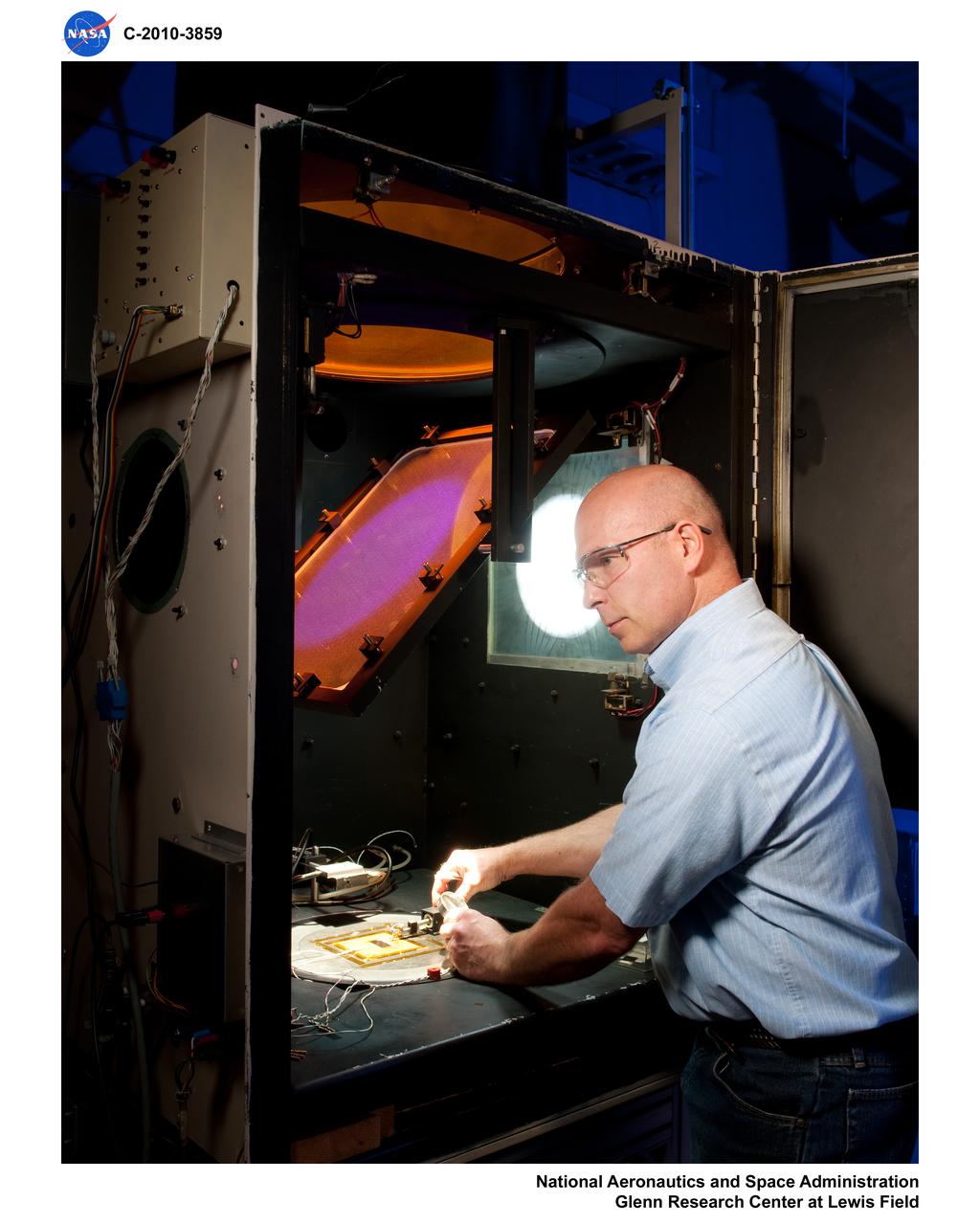
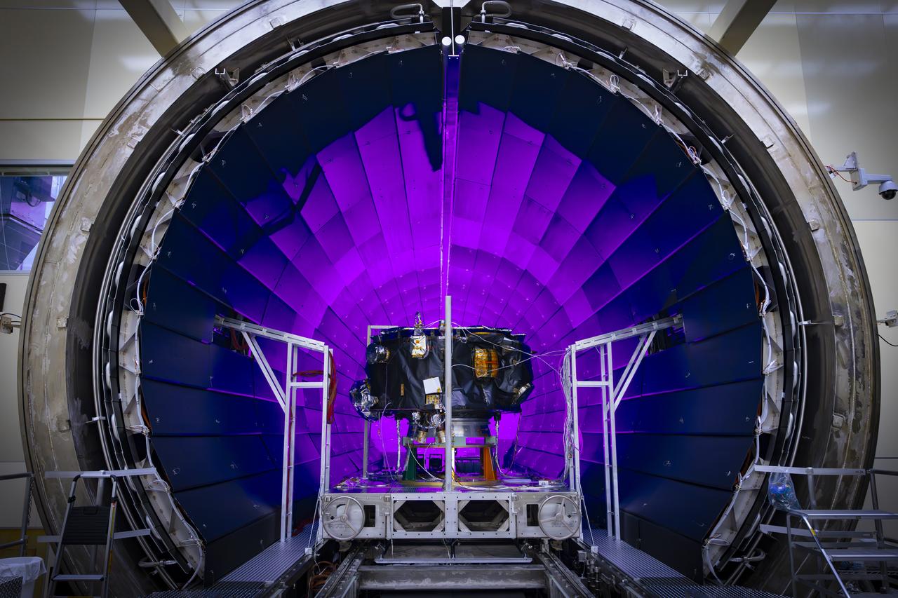
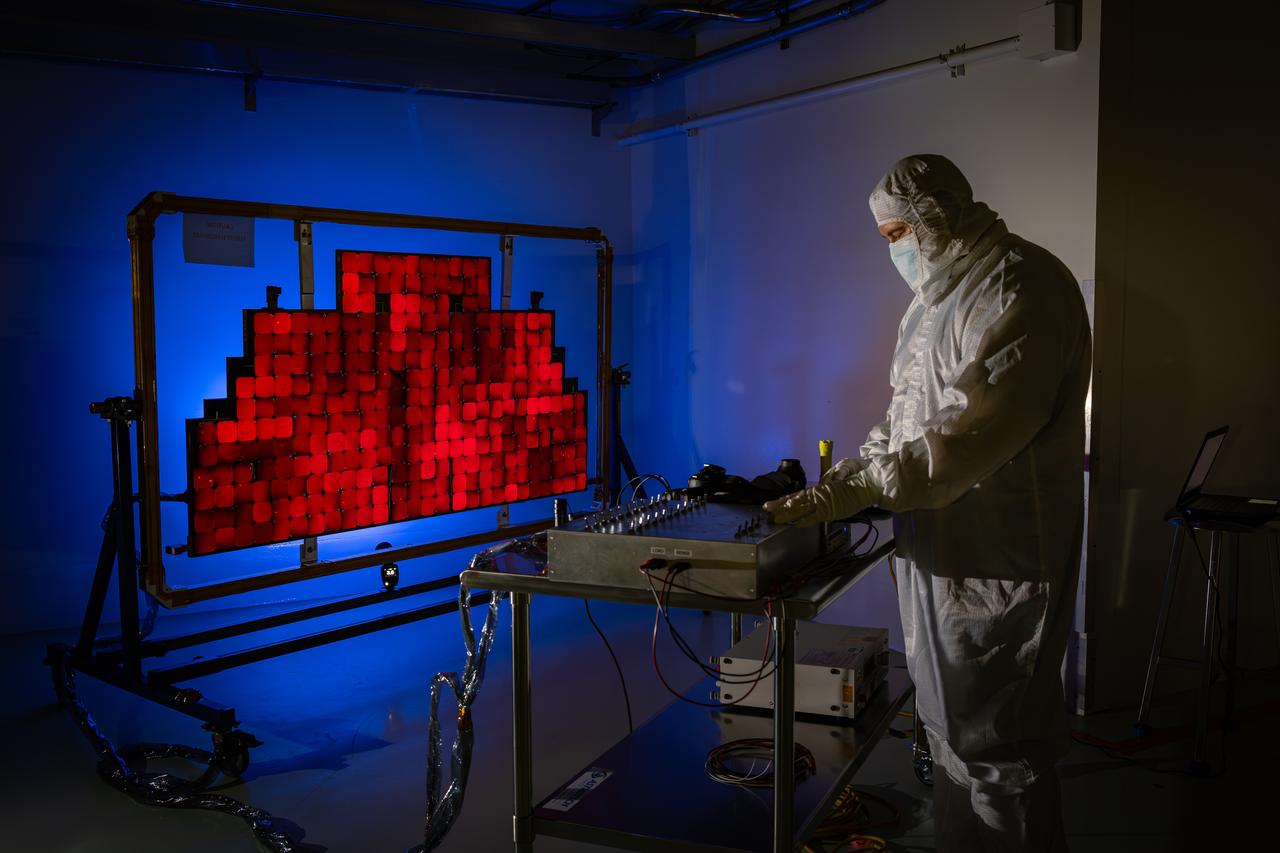
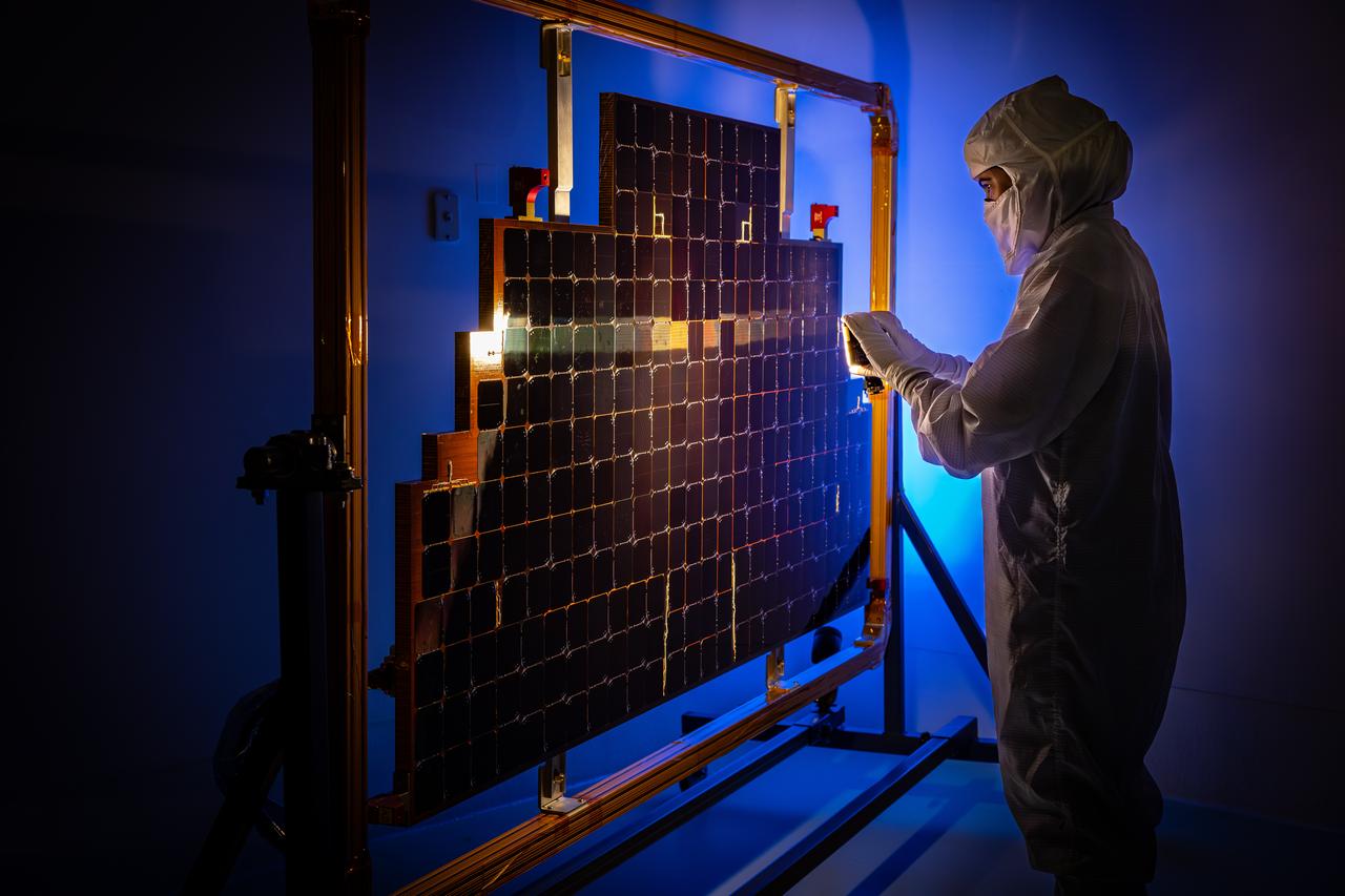
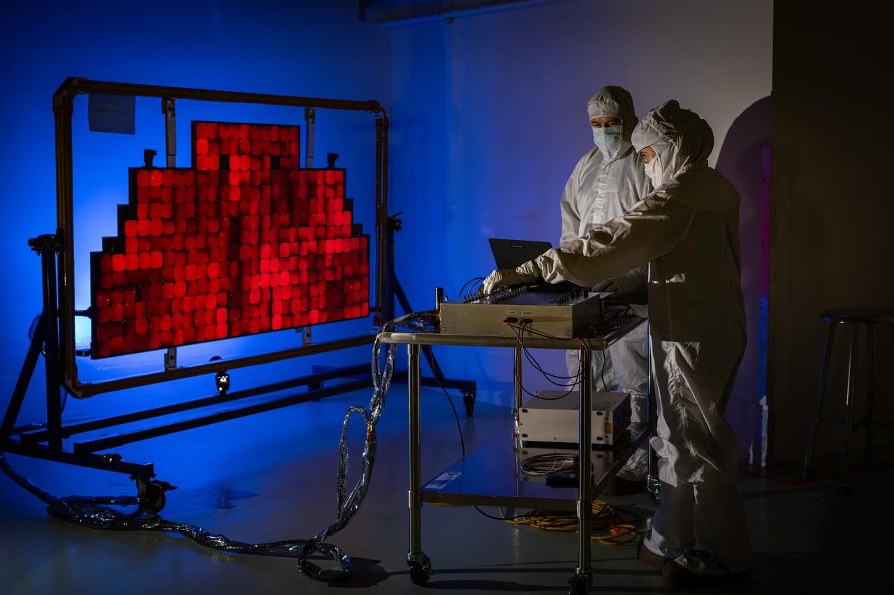
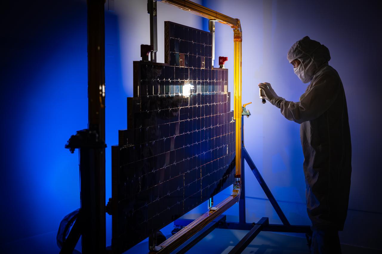
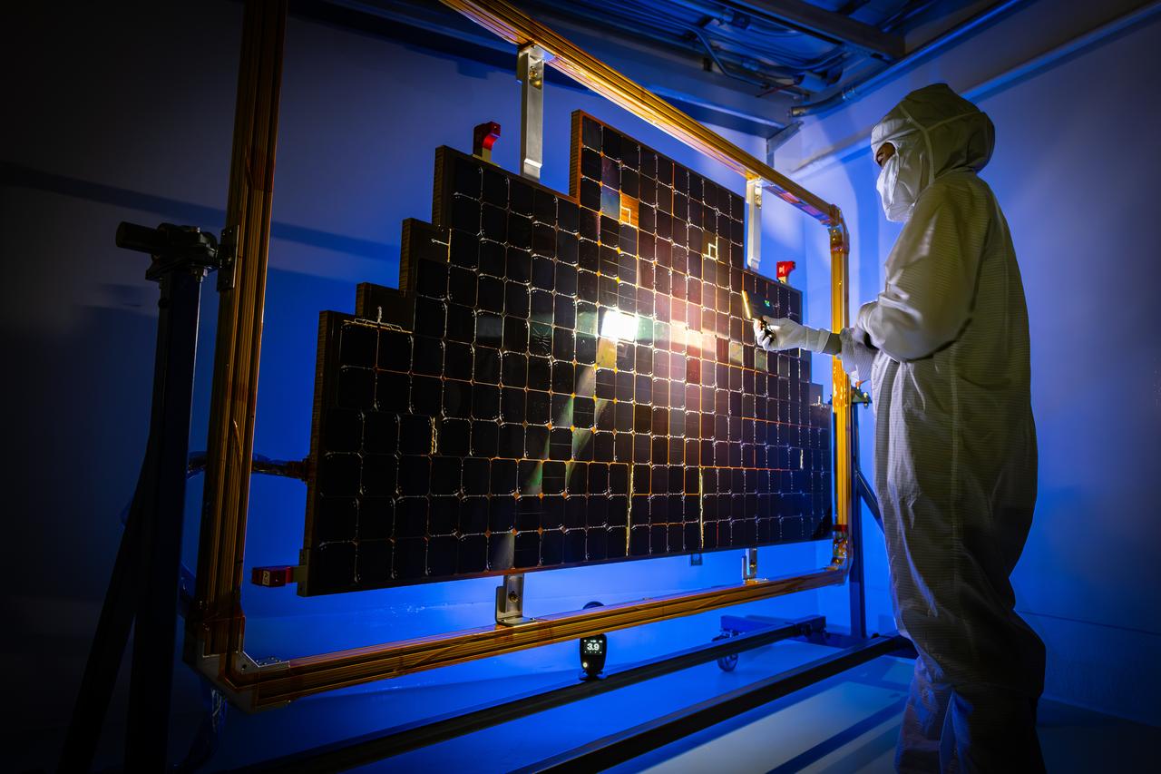
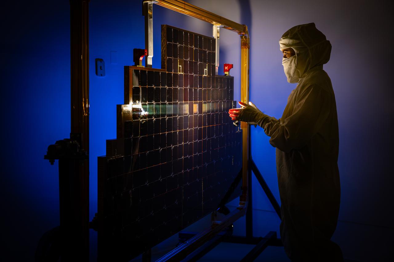
NASA Glenn's new LED solar simulator was developed by Angstrom Designs and UC Santa Barbara under a Small Business Innovative Research program to test the next generation of high-efficiency space solar cells for future missions. The new simulator contains over 1500 individually adjustable light sources, most of which emit light invisible to the human eye, to cover a 10 x10 foot area.
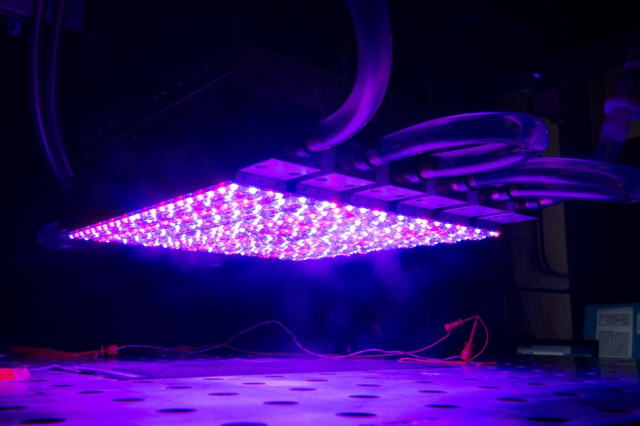
NASA Glenn's new LED solar simulator was developed by Angstrom Designs and UC Santa Barbara under a Small Business Innovative Research program to test the next generation of high-efficiency space solar cells for future missions. The new simulator contains over 1500 individually adjustable light sources, most of which emit light invisible to the human eye, to cover a 10 x10 foot area.

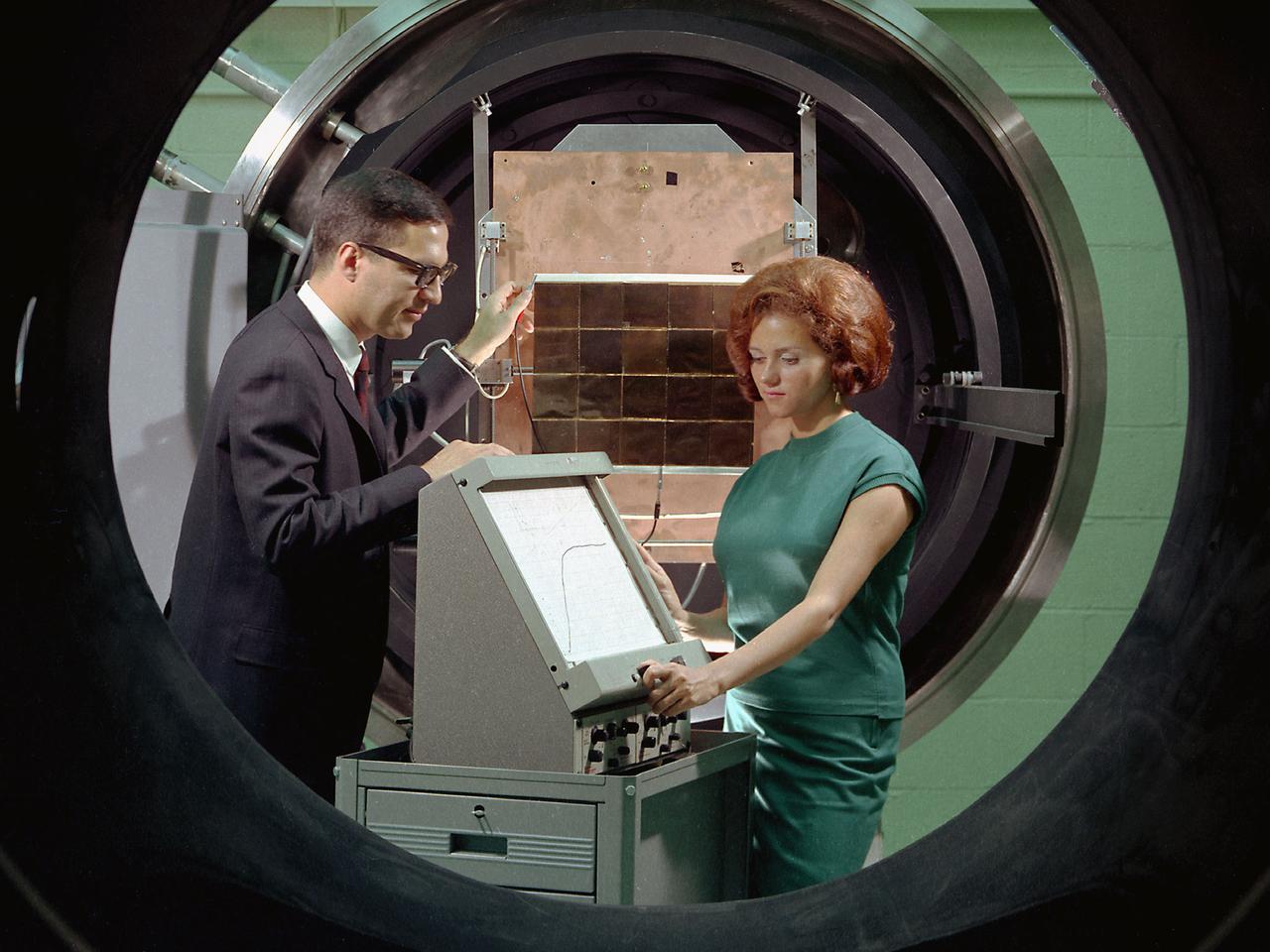
Researcher Susan Johnson and a mechanic examine a flat-plate solar collector in the Solar Simulator Cell in the High Temperature Composites Laboratory at the National Aeronautics and Space Administration (NASA) Lewis Research Center. The Solar Simulator Cell allowed the researchers to control the radiation levels, air temperature, airflow, and fluid flow. The flat-plate collector, seen in a horizontal position here, was directed at the solar simulator, seen above Johnson, during the tests. Lewis researchers were studying the efficiency of various flat- plate solar collector designs in the 1970s for temperature control systems in buildings. The collectors consisted of a cover material, absorber plate, and parallel flow configuration. The collector’s absorber material and coating, covers, honeycomb material, mirrors, vacuum, and tube attachment could all be modified. Johnson’s study analyzed 35 collectors. Johnson, a lifelong pilot, joined NASA Lewis in 1974. The flat-plate solar collectors, seen here, were her first research project. Johnson also investigated advanced heat engines for general aviation and evaluated variable geometry combustors and liners. Johnson earned the Cleveland Technical Society’s Technical Achievement Award in 1984.
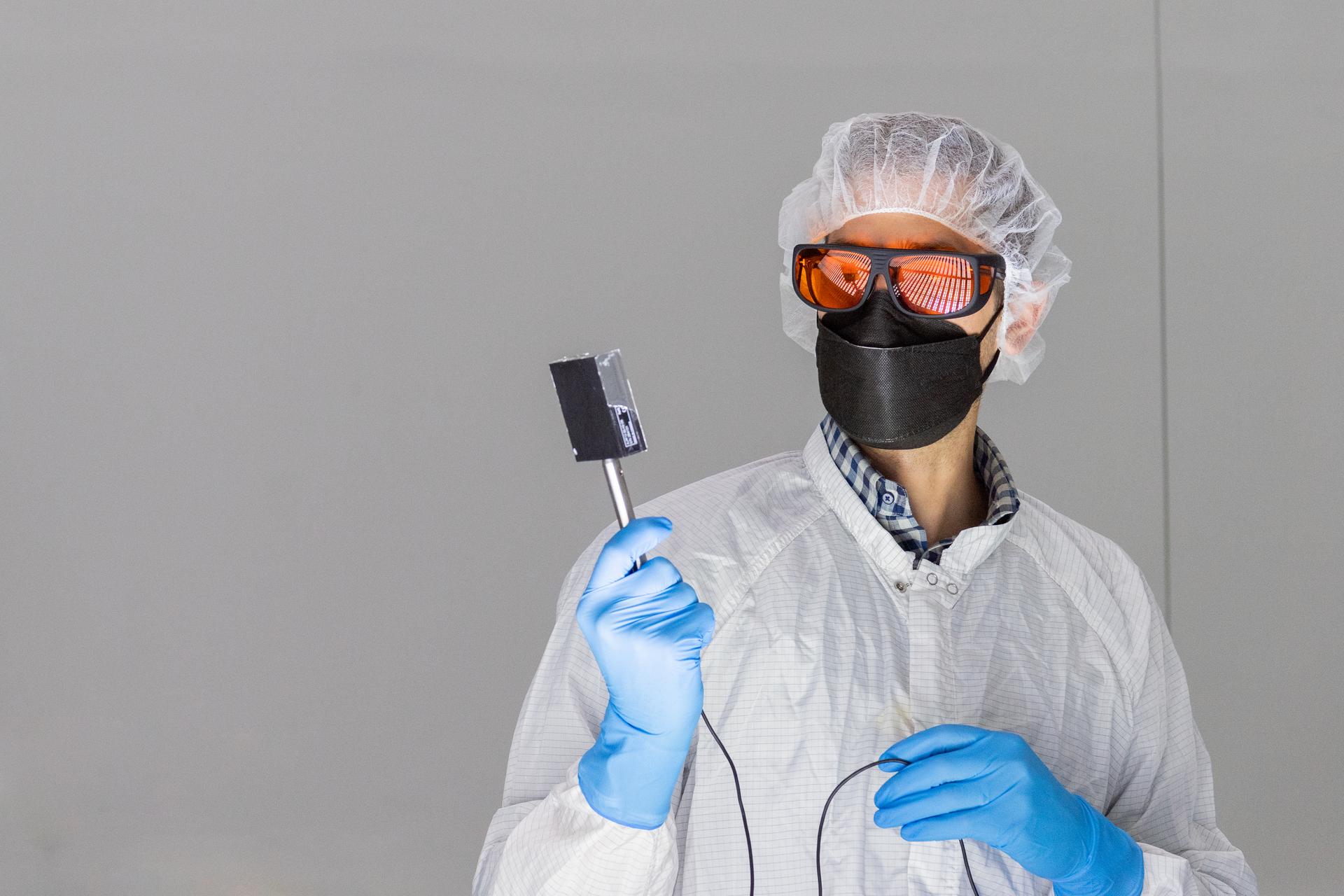
Tucker Ryan Thomas with G2V takes calibration readings from the OSAM-1 solar simulators during their commissioning tests inside a cleanroom at Goddard Space Flight Center, Greenbelt Md., Oct 3, 2022. This photo has been cleared for public release. NASA/Mike Guinto
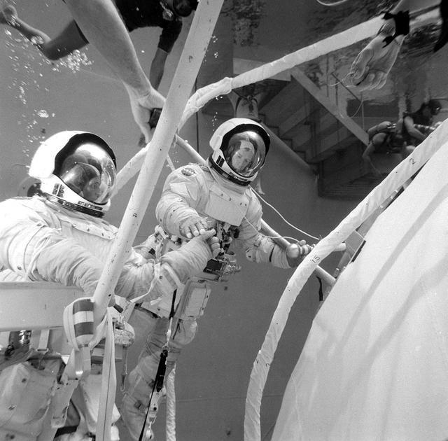
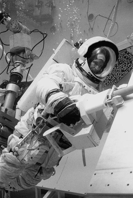
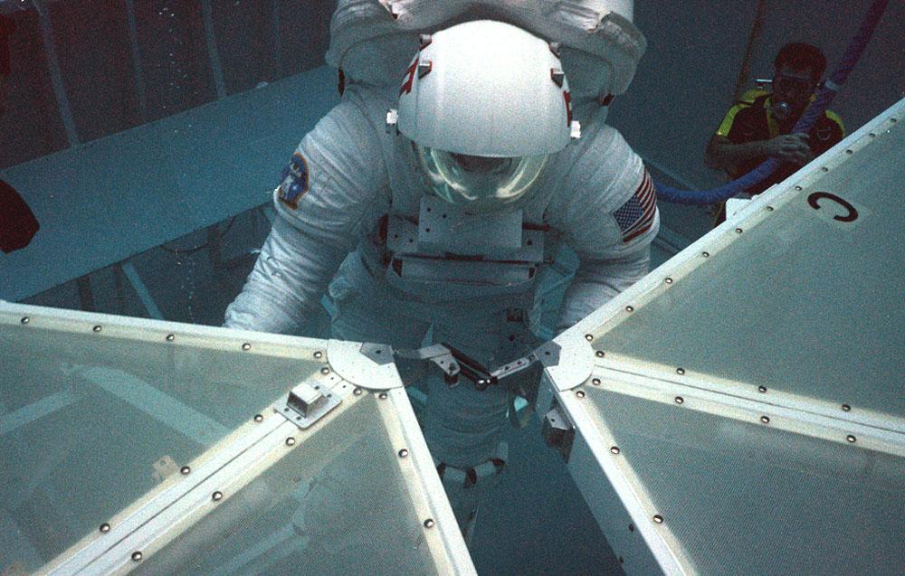
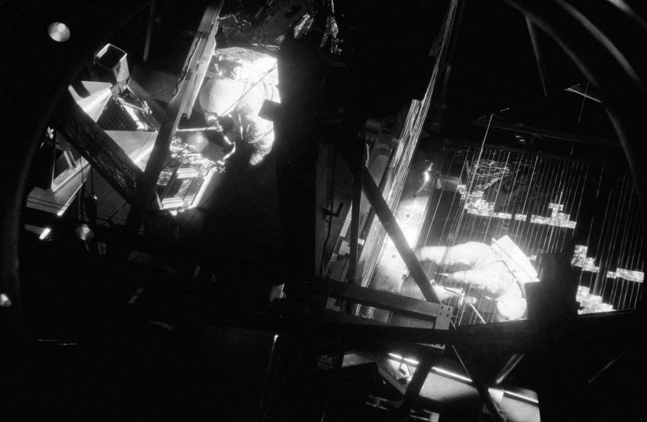
This photograph was taken during testing of an emergency procedure to free jammed solar array panels on the Skylab workshop. A metal strap became tangled over one of the folded solar array panels when Skylab lost its micrometeoroid shield during the launch. This photograph shows astronauts Schweickart and Gibson in the Marshall Space Flight Center (MSFC) Neutral Buoyancy Simulator (NBS) using various cutting tools and methods developed by the MSFC to free the jammed solar wing. Extensive testing and many hours of practice in simulators such as the NBS tank helped prepare the Skylab crewmen for extravehicular performance in the weightless environment. This huge water tank simulated the weightless environment that the astronauts would encounter in space.
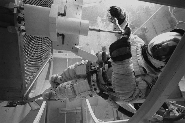
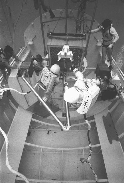
In February 1980, a satellite called Solar Maximum Mission Spacecraft, or Solar Max, was launched into Earth's orbit. Its primary objective was to provide a detailed study of solar flares, active regions on the Sun's surface, sunspots, and other solar activities. Additionally, it was to measure the total output of radiation from the Sun. Not much was known about solar activity at that time except for a slight knowledge of solar flares. After its launch, Solar Max fulfilled everyone's expectations. However, after a year in orbit, Solar Max's Altitude Control System malfunctioned, preventing the precise pointing of instruments at the Sun. NASA scientists were disappointed at the lost data, but not altogether dismayed because Solar Max had been designed for Space Shuttle retrievability enabling repair of the satellite. On April 6, 1984, Space Shuttle Challenger (STS-41C), Commanded by astronaut Robert L. Crippen and piloted by Francis R. Scobee, launched on a historic voyage. This voyage initiated a series of firsts for NASA; the first satellite retrieval, the first service use of a new space system called the Marned Maneuvering Unit (MMU), the first in-orbit repair, the first use of the Remote Manipulator System (RMS), and the Space Shuttle Challenger's first space flight. The mission was successful in retrieving Solar Max. Mission Specialist Dr. George D. Nelson, using the MMU, left the orbiter's cargo bay and rendezvoused with Solar Max. After attaching himself to the satellite, he awaited the orbiter to maneuver itself nearby. Using the RMS, Solar Max was captured and docked in the cargo bay while Dr. Nelson replaced the altitude control system and the coronagraph/polarimeter electronics box. After the repairs were completed, Solar Max was redeposited in orbit with the assistance of the RMS. Prior to the April 1984 launch, countless man-hours were spent preparing for this mission. The crew of Challenger spent months at Marshall Space Flight Center's (MSFC) Neutral Buoyancy Simulator (NBS) practicing retrieval maneuvers, piloting the MMU, and training on equipment so they could make the needed repairs to Solar Max. Pictured is Dr. Nelson performing a replacement task on the Solar Max mock-up in the NBS.
In February 1980, a satellite called Solar Maximum Mission Spacecraft, or Solar Max, was launched into Earth's orbit. Its primary objective was to provide a detailed study of solar flares,active regions on the Sun's surface, sunspots, and other solar activities. Additionally, it was to measure the total output of radiation from the Sun. Not much was known about solar activity at that time except for a slight knowledge of solar flares. After its launch, Solar Max fulfilled everyone's expectations. However, after a year in orbit, Solar Max's Altitude Control System malfunctioned, preventing the precise pointing of instruments at the Sun. NASA scientists were disappointed at the lost data, but not altogether dismayed because Solar Max had been designed for Space Shuttle retrievability enabling the repair of the satellite. On April 6, 1984, Space Shuttle Challenger (STS-41C), Commanded by astronaut Robert L. Crippen and piloted by Francis R. Scobee, launched on a historic voyage. This voyage initiated a series of firsts for NASA; the first satellite retrieval, the first service use of a new space system called the Marned Maneuvering Unit (MMU), the first in-orbit repair, the first use of the Remote Manipulator System (RMS), and the Space Shuttle Challenger's first space flight. The mission was successful in retrieving Solar Max. Mission Specialist Dr. George D. Nelson, using the MMU, left the orbiter's cargo bay and rendezvoused with Solar Max. After attaching himself to the satellite, he awaited the orbiter to maneuver itself nearby. Using the RMS, Solar Max was captured and docked in the cargo bay while Dr. Nelson replaced the altitude control system and the coronagraph/polarimeter electronics box. After the repairs were completed, Solar Max was redeposited in orbit with the assistance of the RMS. Prior to the April 1984 launch, countless man-hours were spent preparing for this mission. The crew of Challenger spent months at Marshall Space Flight Center's (MSFC) Neutral Buoyancy Simulator (NBS) practicing retrieval maneuvers, piloting the MMU, and training on equipment so they could make the needed repairs to Solar Max. Pictured is Dr. Nelson performing a replacement task on the Solar Max mock-up in the NBS.
In February 1980, a satellite called Solar Maximum Mission Spacecraft, or Solar Max, was launched into Earth's orbit. Its primary objective was to provide a detailed study of solar flares, active regions on the Sun's surface, sunspots, and other solar activities. Additionally, it was to measure the total output of radiation from the Sun. Not much was known about solar activity at that time except for a slight knowledge of solar flares. After its launch, Solar Max fulfilled everyone's expectations. However, after a year in orbit, Solar Max's Altitude Control System malfunctioned, preventing the precise pointing of instruments at the Sun. NASA scientists were disappointed at the lost data, but not altogether dismayed because Solar Max had been designed for Space Shuttle retrievability enabling the repair of the satellite. On April 6, 1984, Space Shuttle Challenger (STS-41C), Commanded by astronaut Robert L. Crippen and piloted by Francis R. Scobee, launched on a historic voyage. This voyage initiated a series of firsts for NASA; the first satellite retrieval, the first service use of a new space system called the Marned Maneuvering Unit (MMU), the first in-orbit repair, the first use of the Remote Manipulator System (RMS), and the Space Shuttle Challenger's first space flight. The mission was successful in retrieving Solar Max. Mission Specialist Dr. George D. Nelson, using the MMU, left the orbiter's cargo bay and rendezvoused with Solar Max. After attaching himself to the satellite, he awaited the orbiter to maneuver itself nearby. Using the RMS, Solar Max was captured and docked in the cargo bay while Dr. Nelson replaced the altitude control system and the coronagraph/polarimeter electronics box. After the repairs were completed, Solar Max was redeposited in orbit with the assistance of the RMS. Prior to the April 1984 launch, countless man-hours were spent preparing for this mission. The crew of Challenger spent months at Marshall Space Flight Center's (MSFC) Neutral Buoyancy Simulator (NBS) practicing retrieval maneuvers, piloting the MMU, and training on equipment so they could make the needed repairs to Solar Max. Pictured is Dr. Nelson performing a replacement task on the Solar Max mock-up in the NBS.
In February 1980, a satellite called Solar Maximum Mission Spacecraft, or Solar Max, was launched into Earth's orbit. Its primary objective was to provide a detailed study of solar flares,active regions on the Sun's surface, sunspots, and other solar activities. Additionally, it was to measure the total output of radiation from the Sun. Not much was known about solar activity at that time except for a slight knowledge of solar flares. After its launch, Solar Max fulfilled everyone's expectations. However, after a year in orbit, Solar Max's Altitude Control System malfunctioned, preventing the precise pointing of instruments at the Sun. NASA scientists were disappointed at the lost data, but not altogether dismayed because Solar Max had been designed for Space Shuttle retrievability, enabling repair to the satellite. On April 6, 1984, Space Shuttle Challenger (STS-41C), Commanded by astronaut Robert L. Crippen and piloted by Francis R. Scobee, launched on a historic voyage. This voyage initiated a series of firsts for NASA; the first satellite retrieval, the first service use of a new space system called the Marned Maneuvering Unit (MMU), the first in-orbit repair, the first use of the Remote Manipulator System (RMS), and the Space Shuttle Challenger's first space flight. The mission was successful in retrieving Solar Max. Mission Specialist Dr. George D. Nelson, using the MMU, left the orbiter's cargo bay and rendezvoused with Solar Max. After attaching himself to the satellite, he awaited the orbiter to maneuver itself nearby. Using the RMS, Solar Max was captured and docked in the cargo bay while Dr. Nelson replaced the altitude control system and the coronagraph/polarimeter electronics box. After the repairs were completed, Solar Max was redeposited in orbit with the assistance of the RMS. Prior to the April 1984 launch, countless man-hours were spent preparing for this mission. The crew of Challenger spent months at Marshall Space Flight Center's (MSFC) Neutral Buoyancy Simulator (NBS) practicing retrieval maneuvers, piloting the MMU, and training on equipment so they could make the needed repairs to Solar Max. Pictured is Dr. Nelson performing a replacement task on the Solar Max mock-up in the NBS.
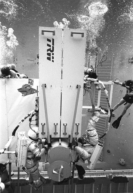
In February 1980, a satellite called Solar Maximum Mission Spacecraft, or Solar Max, was launched into Earth's orbit. Its primary objective was to provide a detailed study of solar flares, active regions on the Sun's surface, sunspots, and other solar activities. Additionally, it was to measure the total output of radiation from the Sun. Not much was known about solar activity at that time except for a slight knowledge of solar flares. After its launch, Solar Max fulfilled everyone's expectations. However, after a year in orbit, Solar Max's Altitude Control System malfunctioned, preventing the precise pointing of instruments at the Sun. NASA scientists were disappointed at the lost data, but not altogether dismayed because Solar Max had been designed for Space Shuttle retrievability enabling the repair of the satellite. On April 6, 1984, Space Shuttle Challenger (STS-41C), Commanded by astronaut Robert L. Crippen and piloted by Francis R. Scobee, launched on a historic voyage. This voyage initiated a series of firsts for NASA; the first satellite retrieval, the first service use of a new space system called the Marned Maneuvering Unit (MMU), the first in-orbit repair, the first use of the Remote Manipulator System (RMS), and the Space Shuttle Challenger's first space flight. The mission was successful in retrieving Solar Max. Mission Specialist Dr. George D. Nelson, using the MMU, left the orbiter's cargo bay and rendezvoused with Solar Max. After attaching himself to the satellite, he awaited the orbiter to maneuver itself nearby. Using the RMS, Solar Max was captured and docked in the cargo bay while Dr. Nelson replaced the altitude control system and the coronagraph/polarimeter electronics box. After the repairs were completed, Solar Max was redeposited in orbit with the assistance of the RMS. Prior to the April 1984 launch, countless man-hours were spent preparing for this mission. The crew of Challenger spent months at Marshall Space Flight Center's (MSFC) Neutral Buoyancy Simulator (NBS) practicing retrieval maneuvers, piloting the MMU, and training on equipment so they could make the needed repairs to Solar Max. Pictured are crew members training on repair tasks.
In February 1980, a satellite called Solar Maximum Mission Spacecraft, or Solar Max, was launched into Earth's orbit. Its primary objective was to provide a detailed study of solar flares, active regions on the Sun's surface, sunspots, and other solar activities. Additionally, it was to measure the total output of radiation from the Sun. Not much was known about solar activity at that time except for a slight knowledge of solar flares. After its launch, Solar Max fulfilled everyone's expectations. However, after a year in orbit, Solar Max's Altitude Control System malfunctioned, preventing the precise pointing of instruments at the Sun. NASA scientists were disappointed at the lost data, but not altogether dismayed because Solar Max had been designed for Space Shuttle retrievability enabling the repair of the satellite. On April 6, 1984, Space Shuttle Challenger (STS-41C), Commanded by astronaut Robert L. Crippen and piloted by Francis R. Scobee, launched on a historic voyage. This voyage initiated a series of firsts for NASA; the first satellite retrieval, the first service use of a new space system called the Marned Maneuvering Unit (MMU), the first in-orbit repair, the first use of the Remote Manipulator System (RMS), and the Space Shuttle Challenger's first space flight. The mission was successful in retrieving Solar Max. Mission Specialist Dr. George D. Nelson, using the MMU, left the orbiter's cargo bay and rendezvoused with Solar Max. After attaching himself to the satellite, he awaited the orbiter to maneuver itself nearby. Using the RMS, Solar Max was captured and docked in the cargo bay while Dr. Nelson replaced the altitude control system and the coronagraph/polarimeter electronics box. After the repairs were completed, Solar Max was redeposited in orbit with the assistance of the RMS. Prior to the April 1984 launch, countless man-hours were spent preparing for this mission. The crew of Challenger spent months at Marshall Space Flight Center's (MSFC) Neutral Buoyancy Simulator (NBS) practicing retrieval maneuvers, piloting the MMU, and training on equipment so they could make the needed repairs to Solar Max. Pictured are crew members training for repair tasks.
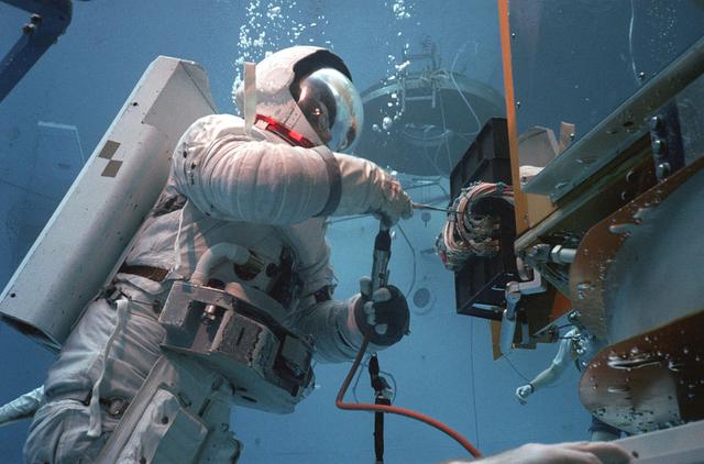
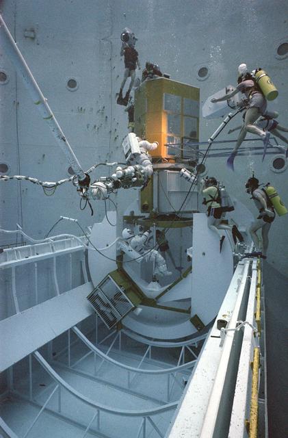
The Space Platform was first conceived as a launching site for deep space exploration. The original idea was to build this space platform either on the moon's surface or near lunar orbit. It would be used as a staging base, where the reusable launch vehicles (later known as Space Shuttles) would ferry machinery and equipment to assemble deep space exploration vehicles. Replaced by the Space Station concept, the space platform idea was never completed. However, early in the space platform development, astronauts trained at the Marshall Space Flight Center's (MSFC) Neutral Buoyancy Simulator (NBS), as pictured here, working on solar array equipment. This experiment was deployed from the shuttle to study the motions of large structures in space. Similar arrays will be used on the Space Station and large observatory spacecraft in the future.
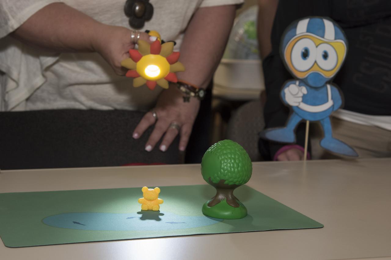
Educators shine a flashlight onto a toy bear to simulate the physics behind solar eclipses.
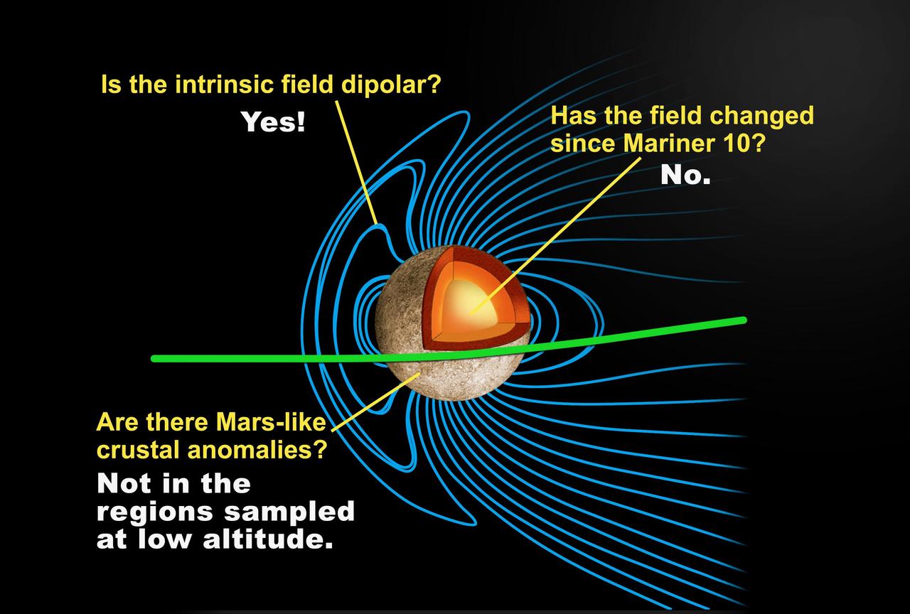
This depiction of a simulated Mercury magnetosphere shows representations of the distortions of the planetary magnetic field lines blue by the solar wind.
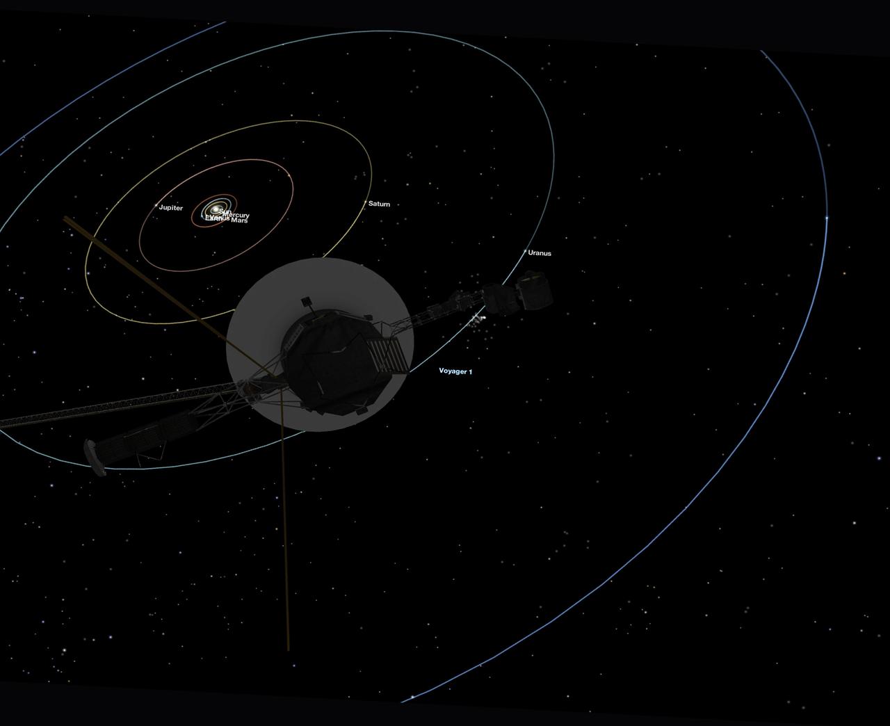
This simulated view, made using NASA's Eyes on the Solar System app, approximates Voyager 1's perspective when it took its final series of images known as the "Family Portrait of the Solar System," including the "Pale Blue Dot" image. https://photojournal.jpl.nasa.gov/catalog/PIA23681
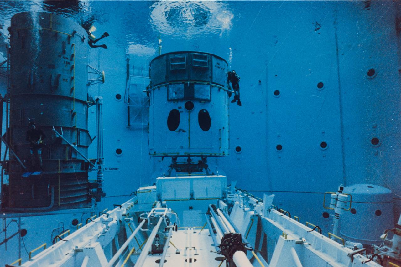
Safety divers in the Neutral Buoyancy Simulator (NBS) at the Marshall Space Flight Center (MSFC) prepare a mockup of the Hubble Space Telescope (HST) for one of 32 separate training sessions conducted by four of the STS-61 crew members in June. The three-week process allowed mission trainers to refine the timelines for the five separate spacewalks scheduled to be conducted on the actual mission scheduled for December 1993. The HST is separated into two pieces since the water tank depth cannot support the entire structure in one piece. The full length payload bay mockup shows the Solar Array Carrier in the foreground and the various containers that will house replacement hardware that will be carried on the mission.
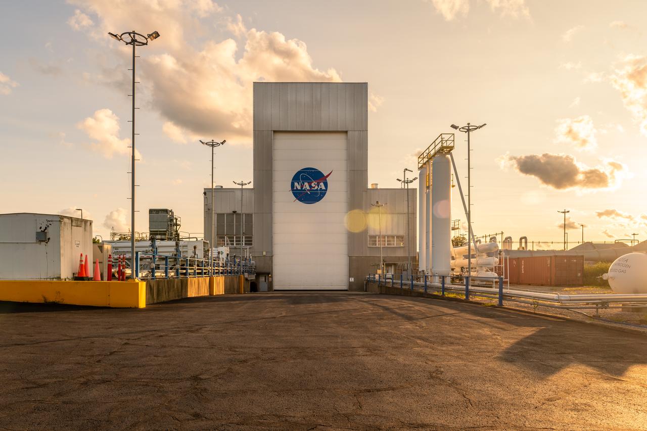
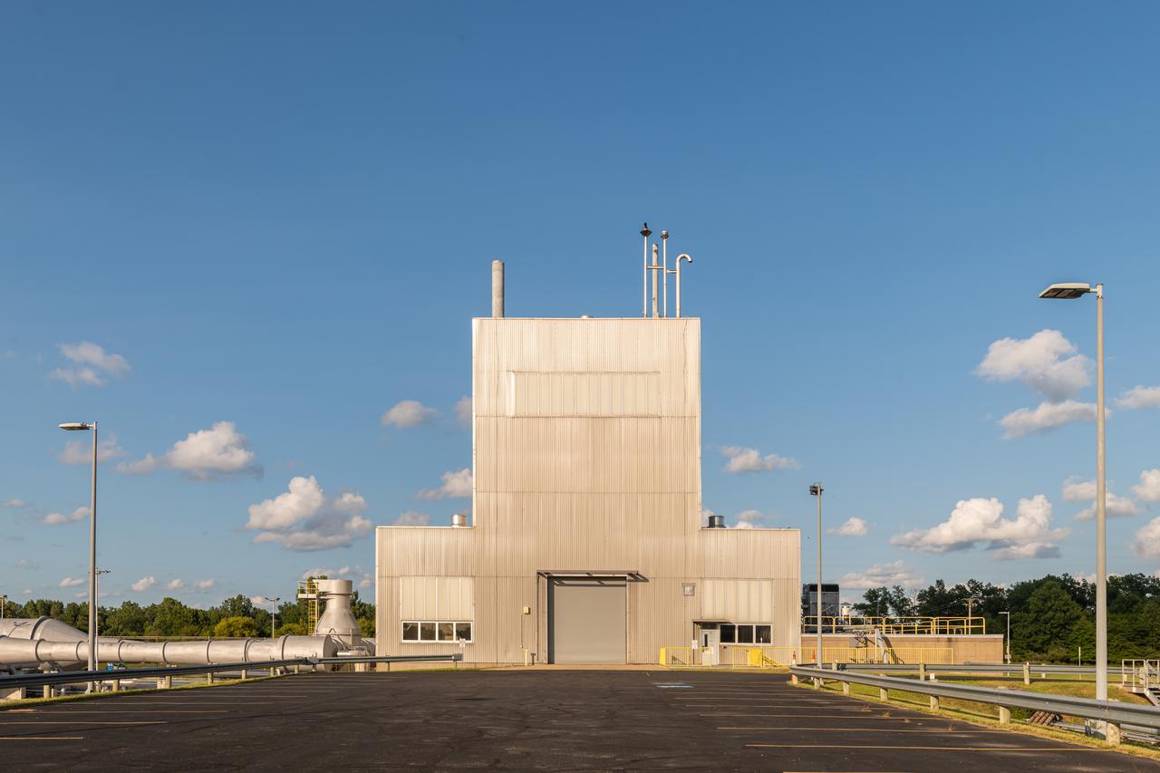
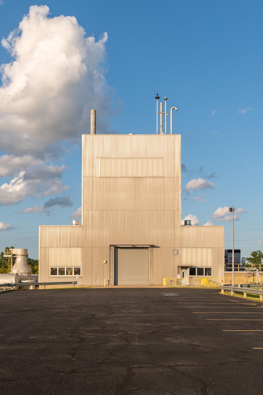
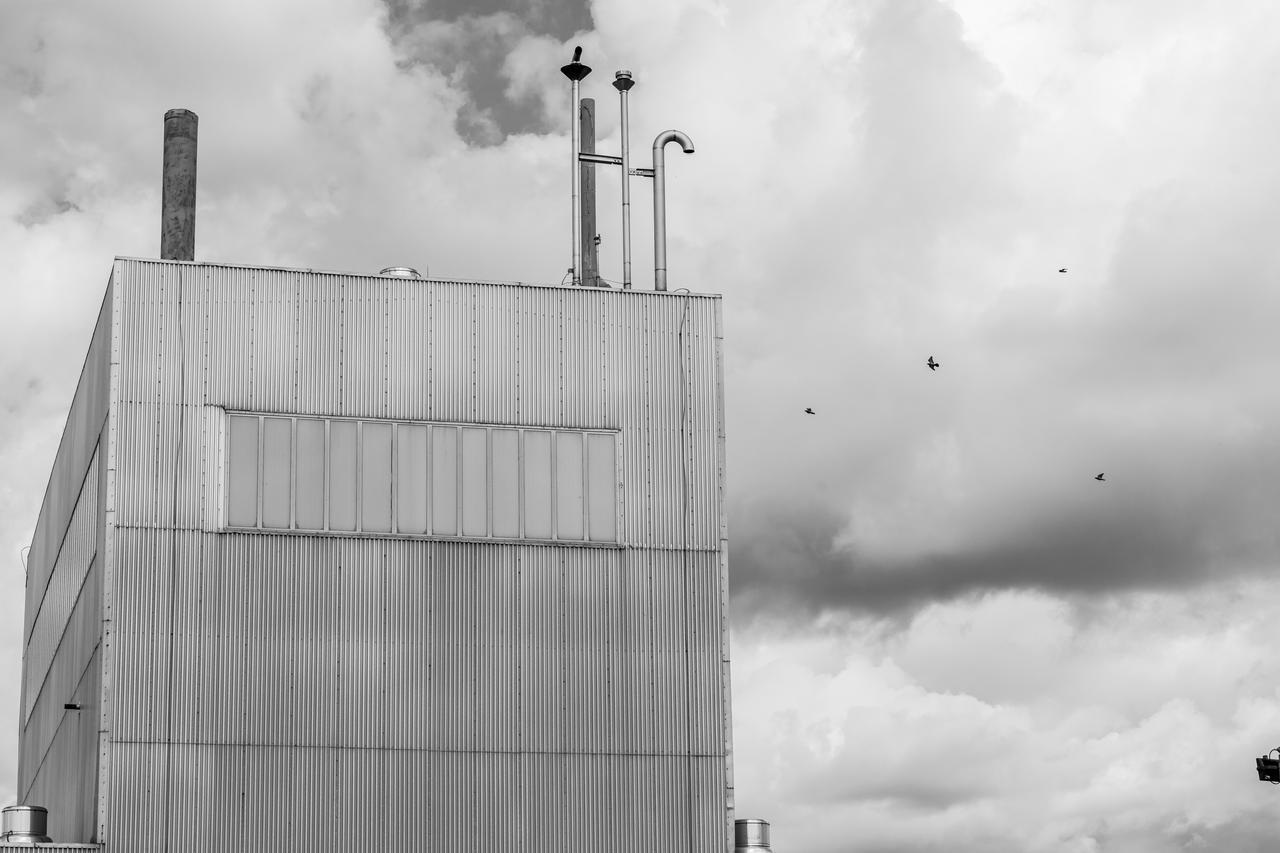
Solar Simulator
Solar Simulator
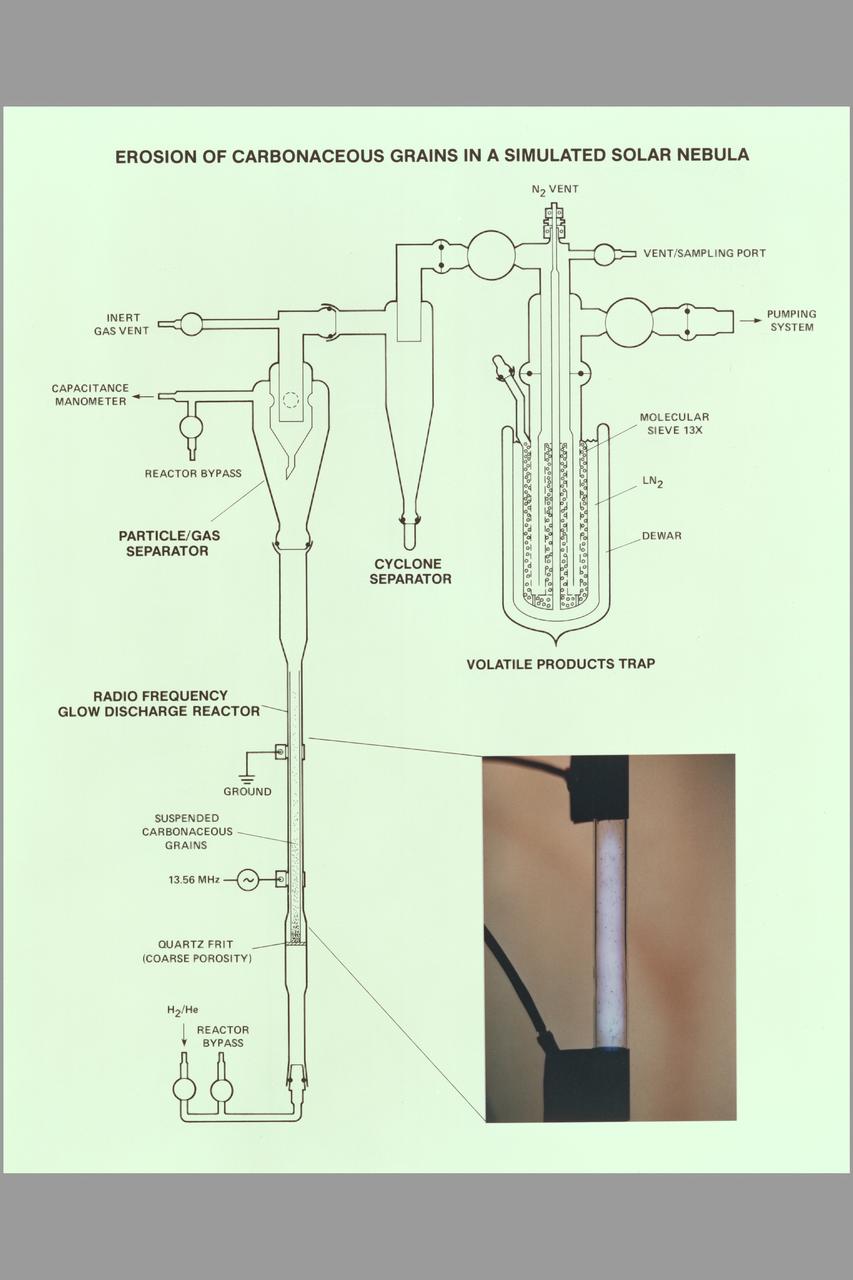
Erosion of Carbonaceous Grains in a Simulated Solar Nebula Composite
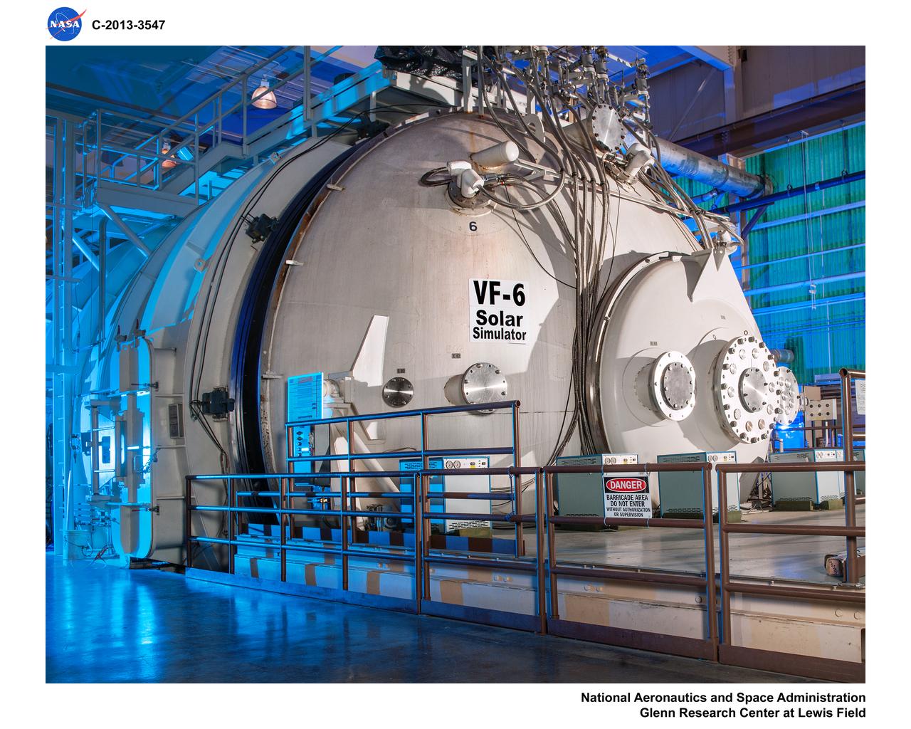
Tank 6, VF-6, Solar Simulator
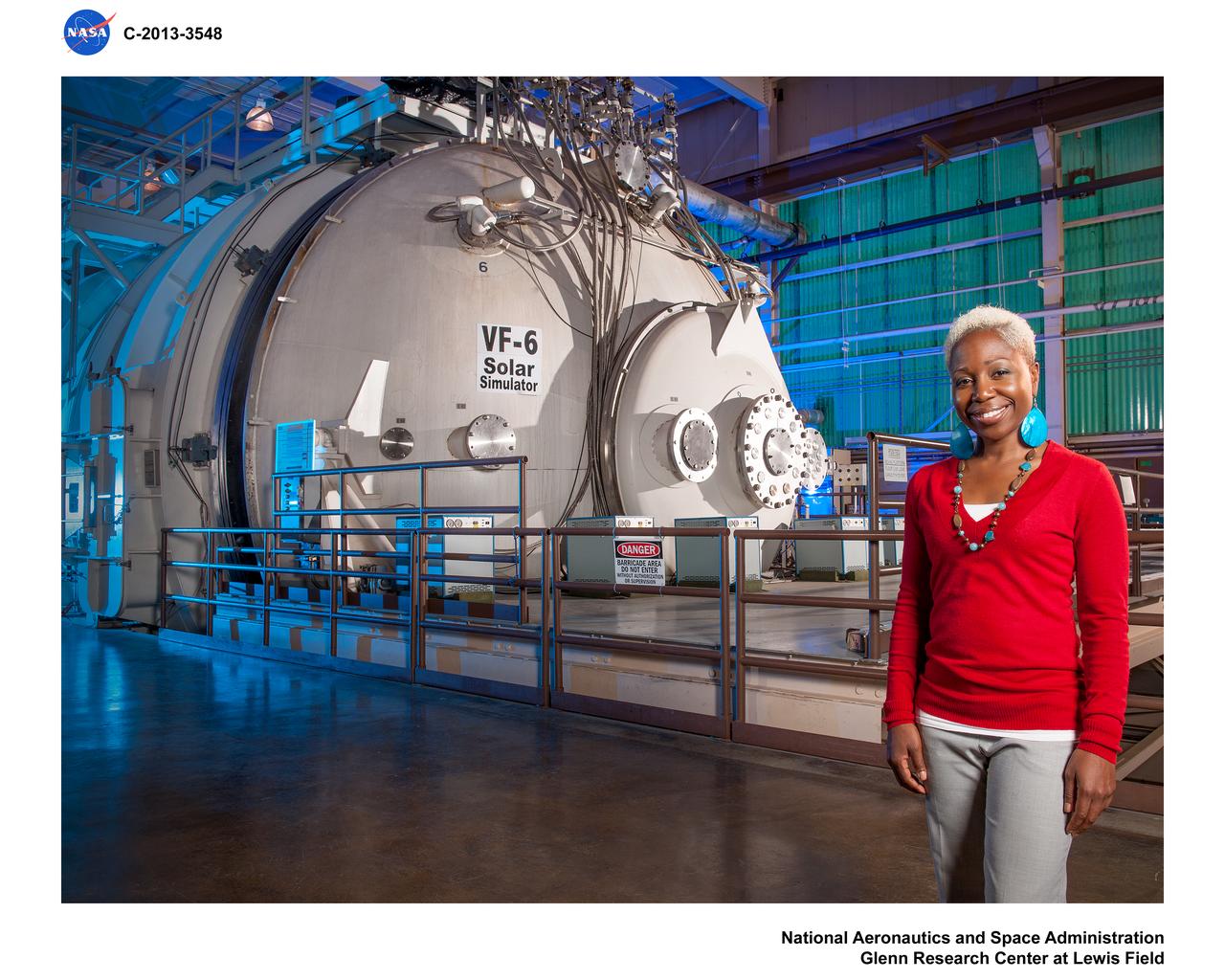
Environmental portrait of Mary Gibson and of Tank 6 (VF-6) Solar Simulator for NASA GRC Web Feature Story
Marshall scientist practices assembling the solar panel array for the space station during the Collector Panel Assembly Test (COPAT) at Marshall's Neutral Buoyancy Simulator (NBS).
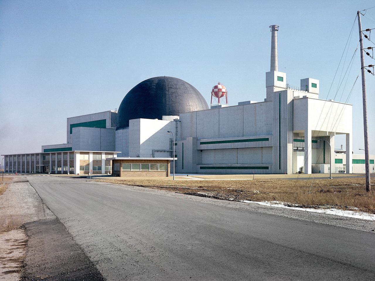
Exterior view of the Space Power Facility at the National Aeronautics and Space Administration’s (NASA) Plum Brook Station in Sandusky, Ohio. The $28.4-million facility, which began operations in 1969, is the largest high vacuum chamber ever built. The chamber is 100 feet in diameter and 120 feet high. It produces a vacuum deep enough to simulate the conditions at 300 miles altitude. The facility can sustain a high vacuum; simulate solar radiation via a 4-megawatt quartz heat lamp array, solar spectrum by a 400-kilowatt arc lamp, and cold environments. The Space Power Facility was originally designed to test nuclear power sources for spacecraft during long durations in a space atmosphere, but it was never used for that purpose. The facility’s first test in 1970 involved a 15 to 20-kilowatt Brayton Cycle Power System for space applications. Three different methods of simulating solar heat were employed during the Brayton tests. The facility was also used for jettison tests of the Centaur Standard Shroud. The shroud was designed for the new Titan-Centaur rocket that was scheduled to launch the Viking spacecraft to Mars. The new shroud was tested under conditions that simulated the time from launch to the separation of the stages. Test programs at the facility include high-energy experiments, shroud separation tests, Mars Lander system tests, deployable Solar Sail tests and International Space Station hardware tests.
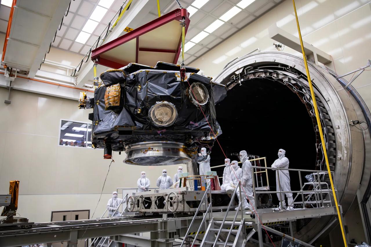
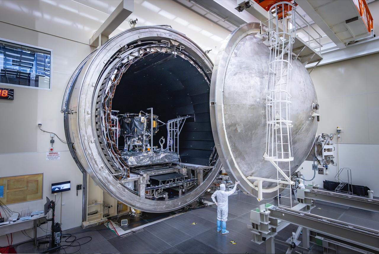
These photos and timelapse show NASA’s IMAP mission being loaded into the thermal vacuum chamber of NASA Marshall Space Flight Center’s X-Ray and Cryogenic Facility (XRCF) in Huntsville, Alabama. IMAP arrived at Marshall March 18 and was loaded into the chamber March 19. IMAP will undergo testing such as dramatic temperature changes to simulate the harsh environment of space. The XRCF’s vacuum chamber is is 20 feet in diameter and 60 feet long making it one of the largest across NASA. The IMAP mission is a modern-day celestial cartographer that will map the solar system by studying the heliosphere, a giant bubble created by the Sun’s solar wind that surrounds our solar system and protects it from harmful interstellar radiation. Photos and video courtesy of Ed Whitman from Johns Hopkins University’s Applied Physics Laboratory. For more information, contact NASA Marshall’s Office of Communications at 256-544-0034.
These photos and timelapse show NASA’s IMAP mission being loaded into the thermal vacuum chamber of NASA Marshall Space Flight Center’s X-Ray and Cryogenic Facility (XRCF) in Huntsville, Alabama. IMAP arrived at Marshall March 18 and was loaded into the chamber March 19. IMAP will undergo testing such as dramatic temperature changes to simulate the harsh environment of space. The XRCF’s vacuum chamber is is 20 feet in diameter and 60 feet long making it one of the largest across NASA. The IMAP mission is a modern-day celestial cartographer that will map the solar system by studying the heliosphere, a giant bubble created by the Sun’s solar wind that surrounds our solar system and protects it from harmful interstellar radiation. Photos and video courtesy of Ed Whitman from Johns Hopkins University’s Applied Physics Laboratory. For more information, contact NASA Marshall’s Office of Communications at 256-544-0034.
These photos and timelapse show NASA’s IMAP mission being loaded into the thermal vacuum chamber of NASA Marshall Space Flight Center’s X-Ray and Cryogenic Facility (XRCF) in Huntsville, Alabama. IMAP arrived at Marshall March 18 and was loaded into the chamber March 19. IMAP will undergo testing such as dramatic temperature changes to simulate the harsh environment of space. The XRCF’s vacuum chamber is is 20 feet in diameter and 60 feet long making it one of the largest across NASA. The IMAP mission is a modern-day celestial cartographer that will map the solar system by studying the heliosphere, a giant bubble created by the Sun’s solar wind that surrounds our solar system and protects it from harmful interstellar radiation. Photos and video courtesy of Ed Whitman from Johns Hopkins University’s Applied Physics Laboratory. For more information, contact NASA Marshall’s Office of Communications at 256-544-0034.
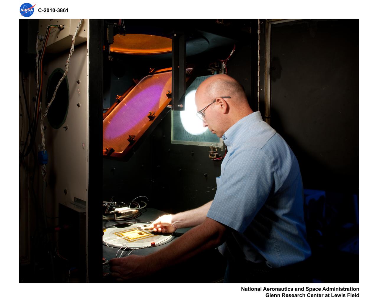
George Mazaris, works with an assistant to obtain the preliminary measurements of cadmium sulfide thin-film solar cells being tested in the Space Environmental Chamber at the National Aeronautics and Space Administration (NASA) Lewis Research Center. Lewis’ Photovoltaic Fundamentals Section was investigating thin-film alternatives to the standard rigid and fragile solar cells. The cadmium sulfide semiconductors were placed in a light, metallized substrate that could be rolled or furled during launch. The main advantage of the thin-film solar cells was their reduced weight. Lewis researchers, however, were still working on improving the performance of the semiconductor. The new thin-film solar cells were tested in a space simulation chamber in the CW-6 test cell in the Engine Research Building. The chamber created a simulated altitude of 200 miles. Sunlight was simulated by a 5000-watt xenon light. Some two dozen cells were exposed to 15 minutes of light followed by 15 minutes of darkness to test their durability in the constantly changing illumination of Earth orbit. This photograph was taken for use in a NASA recruiting publication.
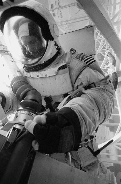
Astronaut Neil A. Armstrong, commander of the Apollo 11 lunar landing mission, is photographed during thermovacuum training in Chamber B of the Space Environment Simulation Laboratory, Building 32, Manned Spacecraft Center. He is wearing an Extravehicular Mobility Unit. The training simulated lunar surface vacuum and thermal conditions during astronaut operations outside the Lunar Module on the moon's surface. The mirror was used to reflect solar light.
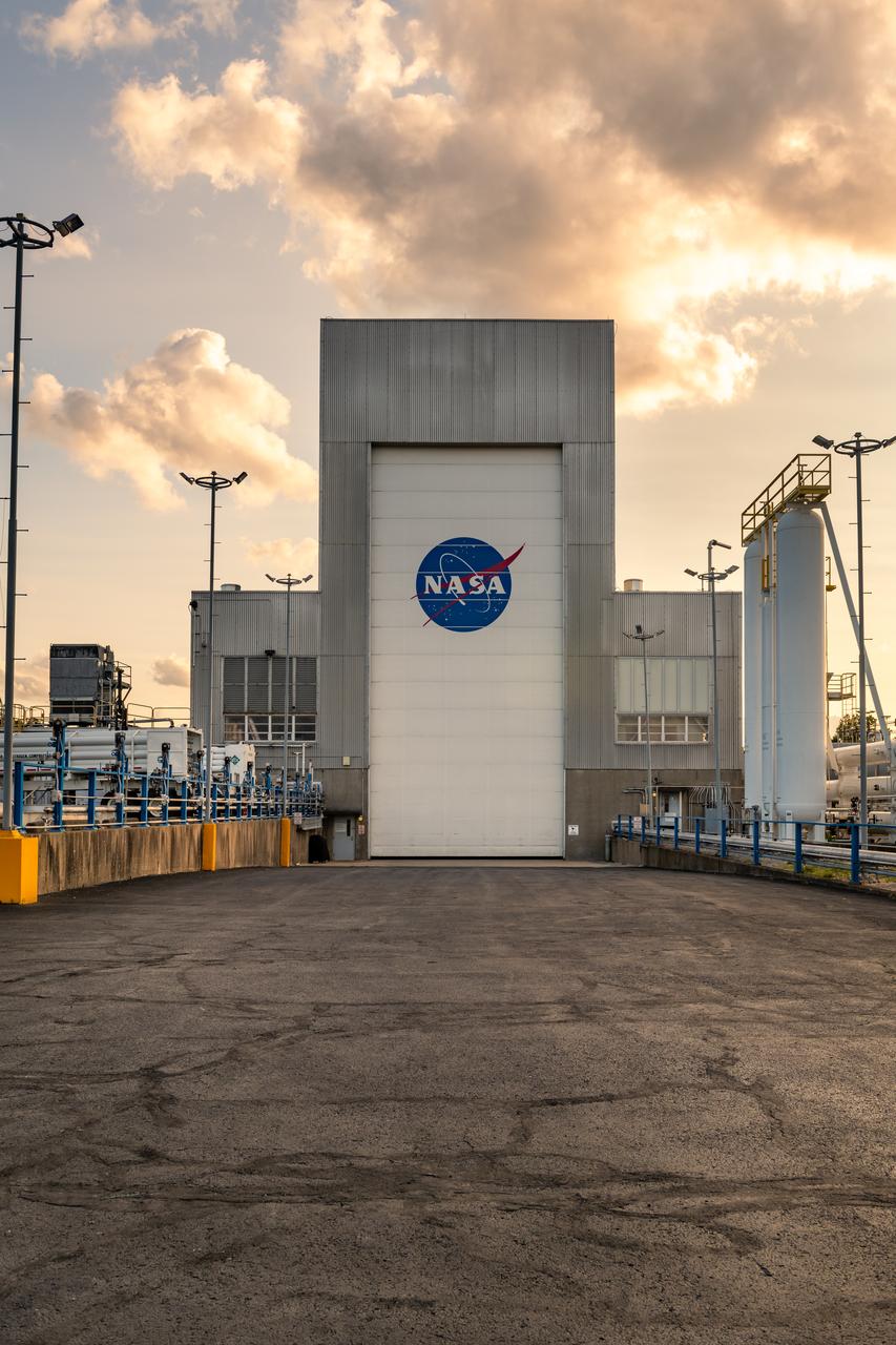
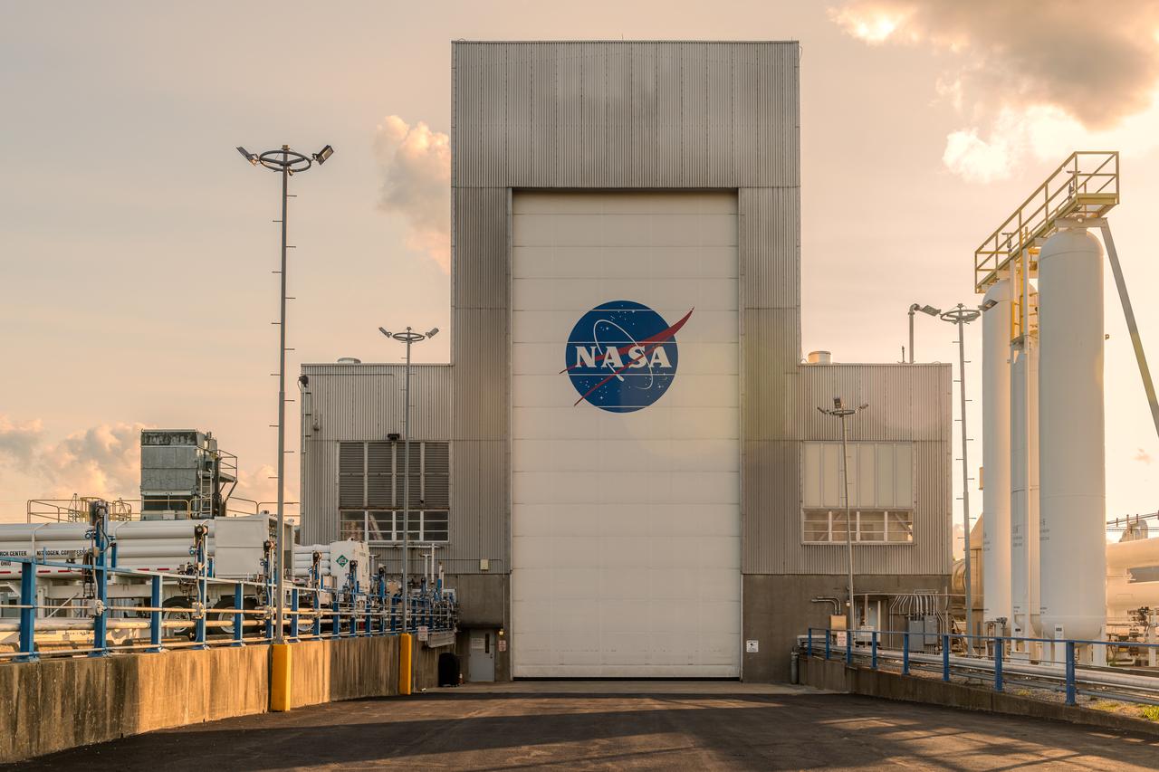
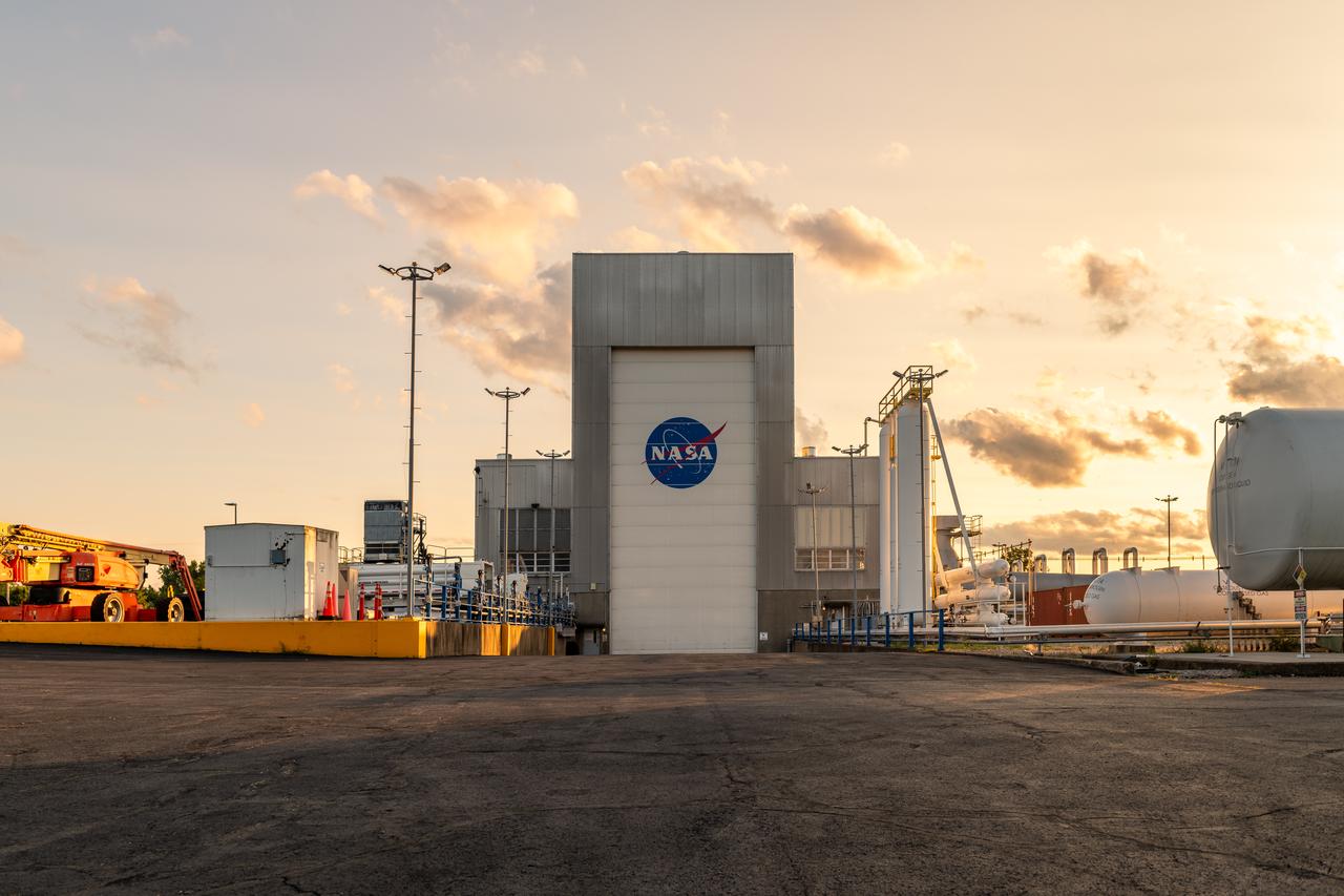
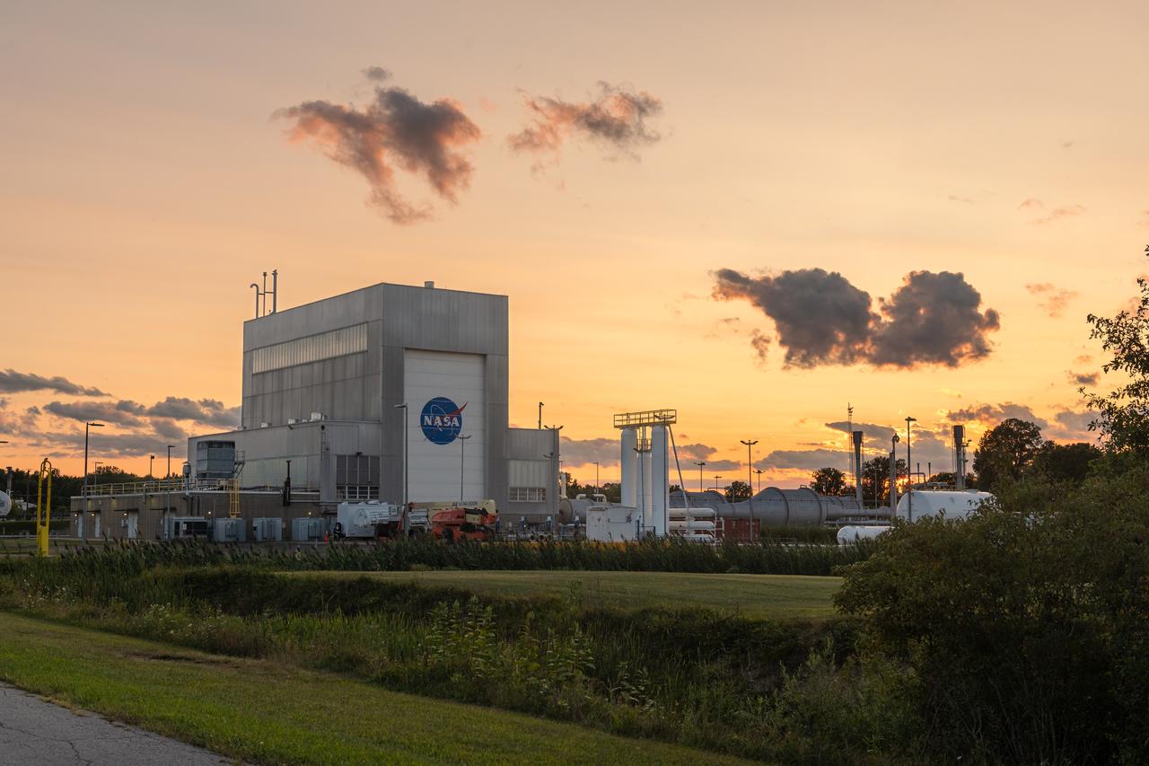
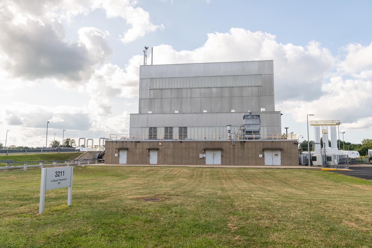
NASA’s In-Space Propulsion Facility located at Neil Armstrong Test Facility in Sandusky Ohio is the world’s only high altitude test facility capable of full-scale rocket engine and launch vehicle system level tests. The facility supports mission profile thermal vacuum simulation and engine firing. The engine or vehicle can be exposed for indefinite periods to low ambient pressures, low-background temperatures, and dynamic solar heating, simulating the environment the hardware will encounter during orbital or interplanetary travel. Photo Credit: (NASA/Jordan Salkin)
NASA’s In-Space Propulsion Facility located at Neil Armstrong Test Facility in Sandusky Ohio is the world’s only high altitude test facility capable of full-scale rocket engine and launch vehicle system level tests. The facility supports mission profile thermal vacuum simulation and engine firing. The engine or vehicle can be exposed for indefinite periods to low ambient pressures, low-background temperatures, and dynamic solar heating, simulating the environment the hardware will encounter during orbital or interplanetary travel. Photo Credit: (NASA/Jordan Salkin)
NASA’s In-Space Propulsion Facility located at Neil Armstrong Test Facility in Sandusky Ohio is the world’s only high altitude test facility capable of full-scale rocket engine and launch vehicle system level tests. The facility supports mission profile thermal vacuum simulation and engine firing. The engine or vehicle can be exposed for indefinite periods to low ambient pressures, low-background temperatures, and dynamic solar heating, simulating the environment the hardware will encounter during orbital or interplanetary travel. Photo Credit: (NASA/Jordan Salkin)
NASA’s In-Space Propulsion Facility located at Neil Armstrong Test Facility in Sandusky Ohio is the world’s only high altitude test facility capable of full-scale rocket engine and launch vehicle system level tests. The facility supports mission profile thermal vacuum simulation and engine firing. The engine or vehicle can be exposed for indefinite periods to low ambient pressures, low-background temperatures, and dynamic solar heating, simulating the environment the hardware will encounter during orbital or interplanetary travel. Photo Credit: (NASA/Jordan Salkin)
NASA’s In-Space Propulsion Facility located at Neil Armstrong Test Facility in Sandusky Ohio is the world’s only high altitude test facility capable of full-scale rocket engine and launch vehicle system level tests. The facility supports mission profile thermal vacuum simulation and engine firing. The engine or vehicle can be exposed for indefinite periods to low ambient pressures, low-background temperatures, and dynamic solar heating, simulating the environment the hardware will encounter during orbital or interplanetary travel. Photo Credit: (NASA/Jordan Salkin)
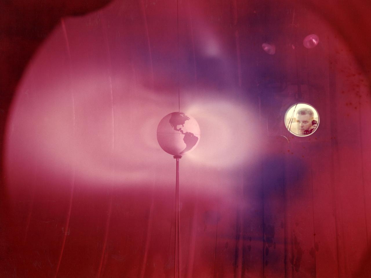
The model of the Earth housed inside Vacuum Tank 5 contained a coil which produced a magnetic field simulating that of the Earth. It was bombarded with a stream of ionized particles simulating the solar wind which impinges on the Earth's magnetic field. The bands or belts of luminous plasma seen in this image were suggestive of the Van Allen belts found around the Earth. Scientists at Lewis probed the plasma around the model and studied scaling laws in an attempt to find an explanation for the actual formation of the Van Allen belt.
NASA’s In-Space Propulsion Facility located at Neil Armstrong Test Facility in Sandusky Ohio is the world’s only high altitude test facility capable of full-scale rocket engine and launch vehicle system level tests. The facility supports mission profile thermal vacuum simulation and engine firing. The engine or vehicle can be exposed for indefinite periods to low ambient pressures, low-background temperatures, and dynamic solar heating, simulating the environment the hardware will encounter during orbital or interplanetary travel. Photo Credit: (NASA/Jordan Salkin)
NASA’s In-Space Propulsion Facility located at Neil Armstrong Test Facility in Sandusky Ohio is the world’s only high altitude test facility capable of full-scale rocket engine and launch vehicle system level tests. The facility supports mission profile thermal vacuum simulation and engine firing. The engine or vehicle can be exposed for indefinite periods to low ambient pressures, low-background temperatures, and dynamic solar heating, simulating the environment the hardware will encounter during orbital or interplanetary travel. Photo Credit: (NASA/Jordan Salkin)
NASA’s In-Space Propulsion Facility located at Neil Armstrong Test Facility in Sandusky Ohio is the world’s only high altitude test facility capable of full-scale rocket engine and launch vehicle system level tests. The facility supports mission profile thermal vacuum simulation and engine firing. The engine or vehicle can be exposed for indefinite periods to low ambient pressures, low-background temperatures, and dynamic solar heating, simulating the environment the hardware will encounter during orbital or interplanetary travel. Photo Credit: (NASA/Jordan Salkin)
NASA’s In-Space Propulsion Facility located at Neil Armstrong Test Facility in Sandusky Ohio is the world’s only high altitude test facility capable of full-scale rocket engine and launch vehicle system level tests. The facility supports mission profile thermal vacuum simulation and engine firing. The engine or vehicle can be exposed for indefinite periods to low ambient pressures, low-background temperatures, and dynamic solar heating, simulating the environment the hardware will encounter during orbital or interplanetary travel. Photo Credit: (NASA/Jordan Salkin)
NASA’s In-Space Propulsion Facility located at Neil Armstrong Test Facility in Sandusky Ohio is the world’s only high altitude test facility capable of full-scale rocket engine and launch vehicle system level tests. The facility supports mission profile thermal vacuum simulation and engine firing. The engine or vehicle can be exposed for indefinite periods to low ambient pressures, low-background temperatures, and dynamic solar heating, simulating the environment the hardware will encounter during orbital or interplanetary travel. Photo Credit: (NASA/Jordan Salkin)
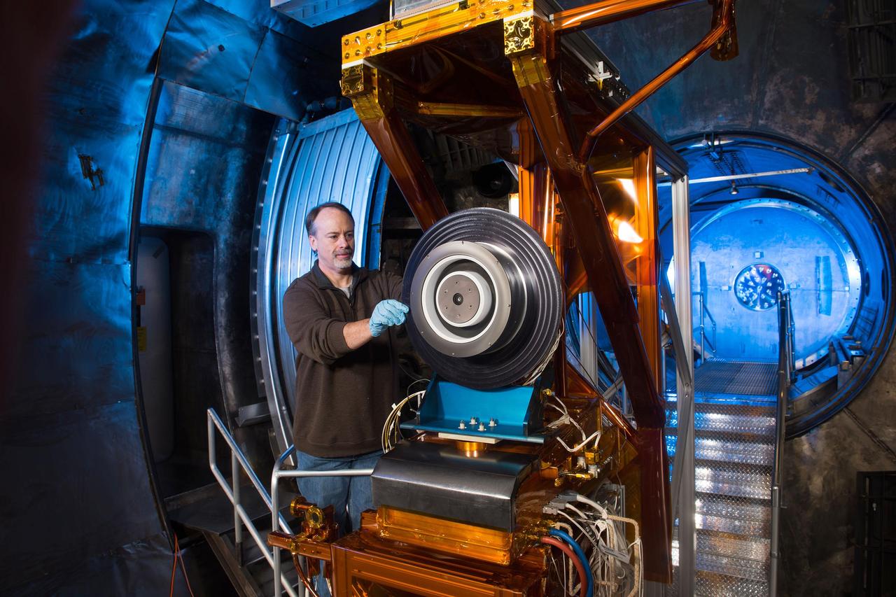
NASA Glenn engineer Dr. Peter Peterson prepares a high-power Hall thruster for ground testing in a vacuum chamber that simulates the environment in space. This high-powered solar electric propulsion thruster has been identified as a critical part of NASA’s future deep space exploration plans.
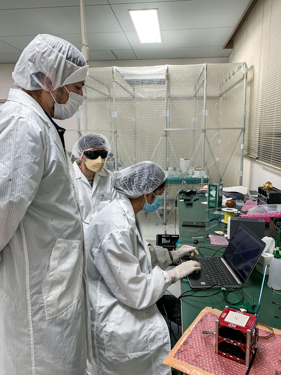
jsc2024e006086 (9/9/2024) --- Some MicroOrbiter-1 team members were analyzing the results from exposing the satellite solar panels to the sun simulator to confirm their generation of power.From left to right : SHRESTHA Hari Ram, MATTEI Giulio, ZANGMO Pema...Image Credit: MOUMNI Fahd.
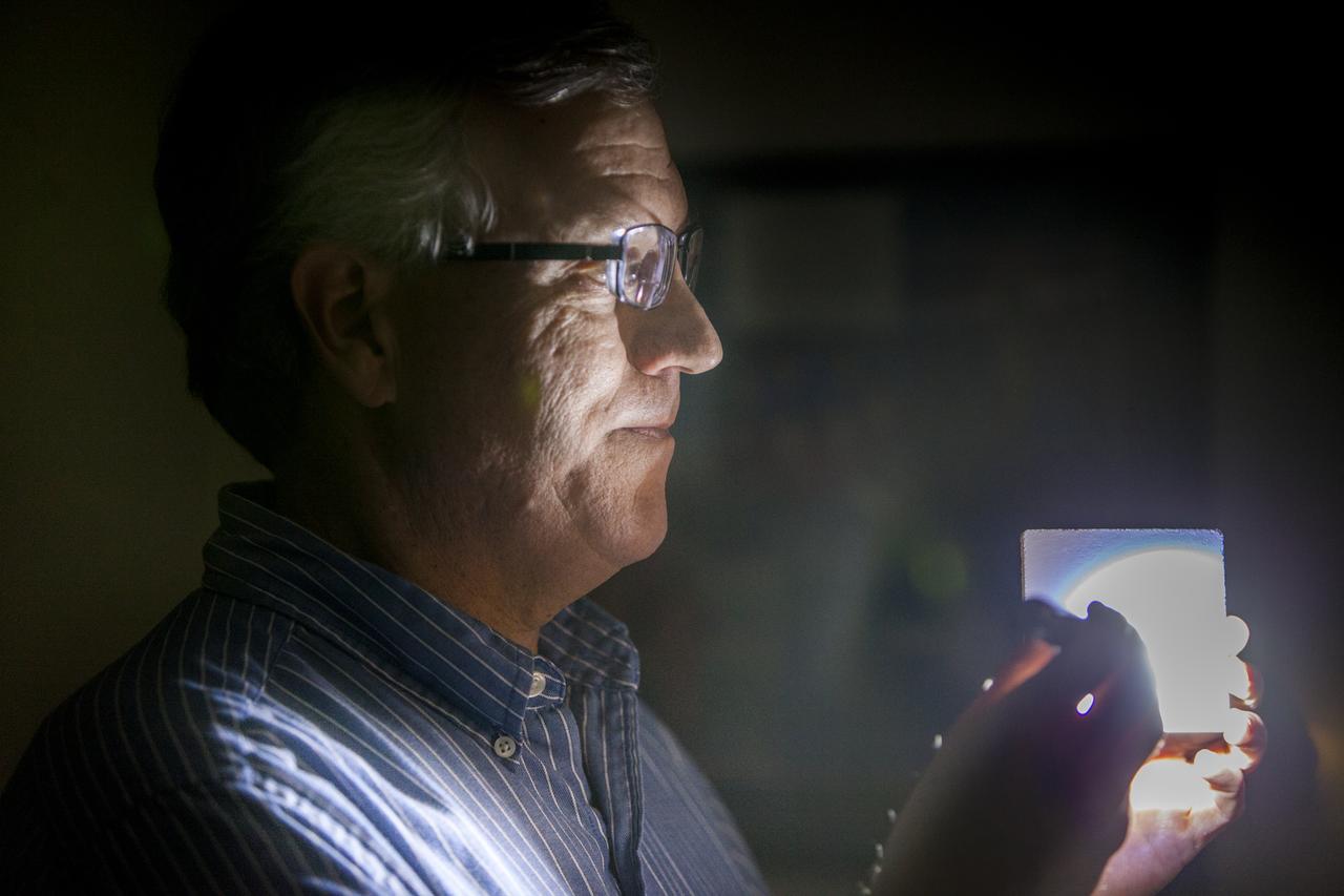
Robert Youngquist, Ph.D., tests a sample disk with a "Solar White" cryogenic selective surface coating with a flash light, demonstrating the coating’s reflective properties. The innovative coating is predicted to reflect more than 99.9 percent of the simulated solar infrared radiation. This technology could enable storing super-cold, or cryogenic, liquids and support systems that shield astronauts against radiation during the Journey to Mars.
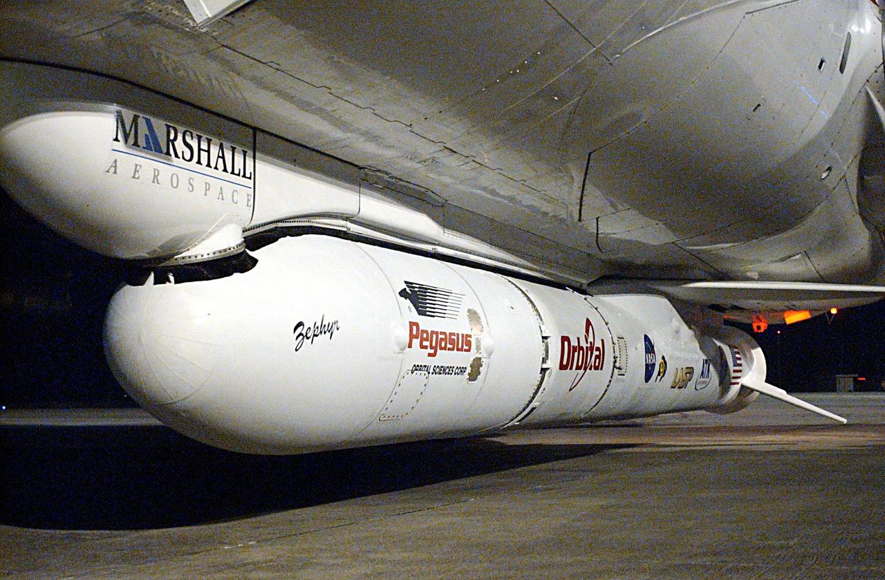
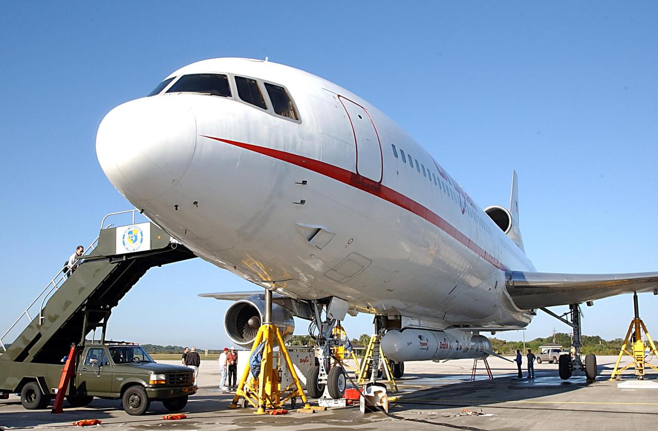
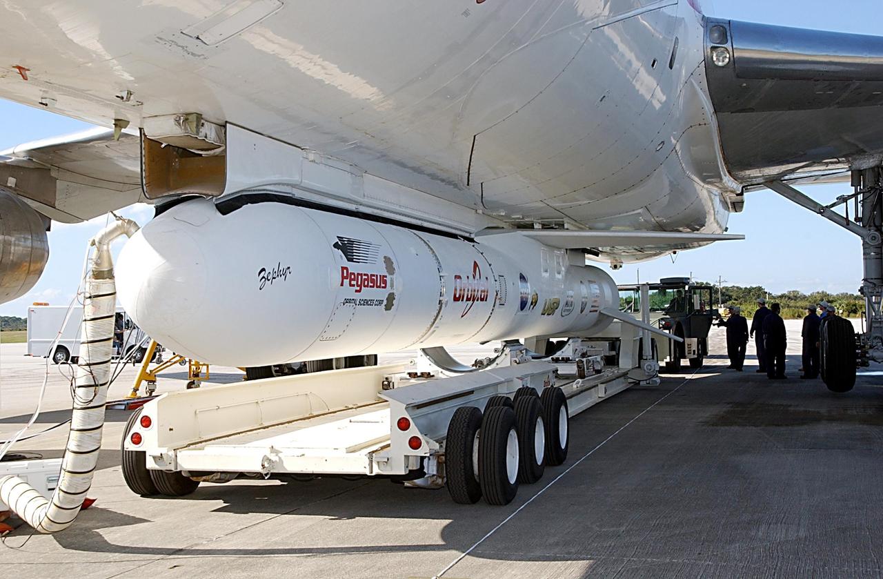
KENNEDY SPACE CENTER, FLA. -- Attached underneath the Orbital Sciences L-1011 aircraft is the Pegasus XL Expendable Launch Vehicle, which will be transported to the Multi-Payload Processing Facility for testing and verification. The Pegasus will undergo three flight simulations prior to its scheduled launch in late January 2003. The Pegasus XL will carry NASA's Solar Radiation and Climate Experiment (SORCE) into orbit. Built by Orbital Sciences Space Systems Group, SORCE will study and measure solar irradiance as a source of energy in the Earth's atmosphere. .
KENNEDY SPACE CENTER, FLA. -- Attached underneath the Orbital Sciences L-1011 aircraft is the Pegasus XL Expendable Launch Vehicle, which will be transported to the Multi-Payload Processing Facility for testing and verification. The Pegasus will undergo three flight simulations prior to its scheduled launch in late January 2003. The Pegasus XL will carry NASA's Solar Radiation and Climate Experiment (SORCE) into orbit. Built by Orbital Sciences Space Systems Group, SORCE will study and measure solar irradiance as a source of energy in the Earth's atmosphere. .
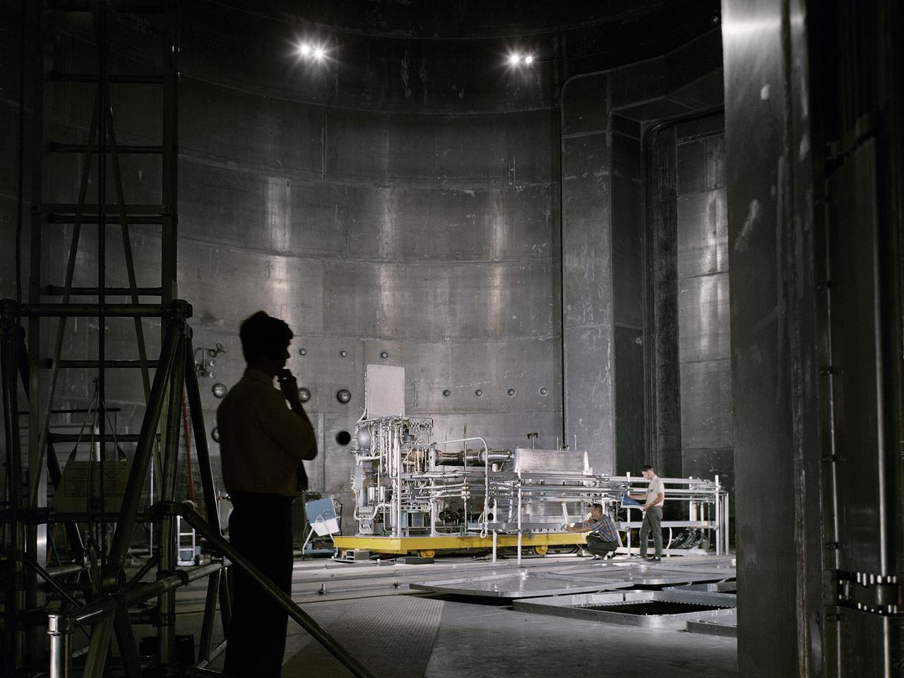
Set up of a Brayton Cycle Power System test in the Space Power Facility’s massive vacuum chamber at the National Aeronautics and Space Administration’s (NASA) Plum Brook Station in Sandusky, Ohio. The $28.4-million facility, which began operations in 1969, is the largest high vacuum chamber ever built. The chamber is 100 feet in diameter and 120 feet high. It can produce a vacuum deep enough to simulate the conditions at 300 miles altitude. The Space Power Facility was originally designed to test nuclear-power sources for spacecraft, but it was never used for that purpose. The Space Power Facility was first used to test a 15 to 20-kilowatt Brayton Cycle Power System for space applications. Three different methods of simulating solar heat were employed during the tests. Lewis researchers studied the Brayton power system extensively in the 1960s and 1970s. The Brayton engine converted solar thermal energy into electrical power. The system operated on a closed-loop Brayton thermodynamic cycle with a helium-xenon gas mixture as its working fluid. A space radiator was designed to serve as the system’s waste heat rejecter. The radiator was later installed in the vacuum chamber and tested in a simulated space environment to determine its effect on the power conversion system. The Brayton system was subjected to simulated orbits with 62 minutes of sun and 34 minutes of shade.
Technicians conduct an illumination test by flashing a bright light that simulates the Sun into the solar array for NASA’s IMAP (Interstellar Mapping and Acceleration Probe) observatory inside the high bay at the Astrotech Space Operations Facility near the agency’s Kennedy Space Center in Florida on Friday, June 20, 2025. The IMAP solar array converts sunlight into approximately 500 watts of power, and IMAP’s spin axis, which comes through the center of the solar arrays, points sunward to provide constant power. Launch is targeted for no earlier than September 2025 aboard a SpaceX Falcon 9 rocket from Launch Complex 39A at NASA Kennedy.
Technicians conduct an illumination test by flashing a bright light that simulates the Sun into the solar array for NASA’s IMAP (Interstellar Mapping and Acceleration Probe) observatory inside the high bay at the Astrotech Space Operations Facility near the agency’s Kennedy Space Center in Florida on Friday, June 20, 2025. The IMAP solar array converts sunlight into approximately 500 watts of power, and IMAP’s spin axis, which comes through the center of the solar arrays, points sunward to provide constant power. Launch is targeted for no earlier than September 2025 aboard a SpaceX Falcon 9 rocket from Launch Complex 39A at NASA Kennedy.
Technicians conduct an illumination test by flashing a bright light that simulates the Sun into the solar array for NASA’s IMAP (Interstellar Mapping and Acceleration Probe) observatory inside the high bay at the Astrotech Space Operations Facility near the agency’s Kennedy Space Center in Florida on Friday, June 20, 2025. The IMAP solar array converts sunlight into approximately 500 watts of power, and IMAP’s spin axis, which comes through the center of the solar arrays, points sunward to provide constant power. Launch is targeted for no earlier than September 2025 aboard a SpaceX Falcon 9 rocket from Launch Complex 39A at NASA Kennedy.
Technicians conduct an illumination test by flashing a bright light that simulates the Sun into the solar array for NASA’s IMAP (Interstellar Mapping and Acceleration Probe) observatory inside the high bay at the Astrotech Space Operations Facility near the agency’s Kennedy Space Center in Florida on Friday, June 20, 2025. The IMAP solar array converts sunlight into approximately 500 watts of power, and IMAP’s spin axis, which comes through the center of the solar arrays, points sunward to provide constant power. Launch is targeted for no earlier than September 2025 aboard a SpaceX Falcon 9 rocket from Launch Complex 39A at NASA Kennedy.
Technicians conduct an illumination test by flashing a bright light that simulates the Sun into the solar array for NASA’s IMAP (Interstellar Mapping and Acceleration Probe) observatory inside the high bay at the Astrotech Space Operations Facility near the agency’s Kennedy Space Center in Florida on Friday, June 20, 2025. The IMAP solar array converts sunlight into approximately 500 watts of power, and IMAP’s spin axis, which comes through the center of the solar arrays, points sunward to provide constant power. Launch is targeted for no earlier than September 2025 aboard a SpaceX Falcon 9 rocket from Launch Complex 39A at NASA Kennedy.
Technicians conduct an illumination test by flashing a bright light that simulates the Sun into the solar array for NASA’s IMAP (Interstellar Mapping and Acceleration Probe) observatory inside the high bay at the Astrotech Space Operations Facility near the agency’s Kennedy Space Center in Florida on Friday, June 20, 2025. The IMAP solar array converts sunlight into approximately 500 watts of power, and IMAP’s spin axis, which comes through the center of the solar arrays, points sunward to provide constant power. Launch is targeted for no earlier than September 2025 aboard a SpaceX Falcon 9 rocket from Launch Complex 39A at NASA Kennedy.
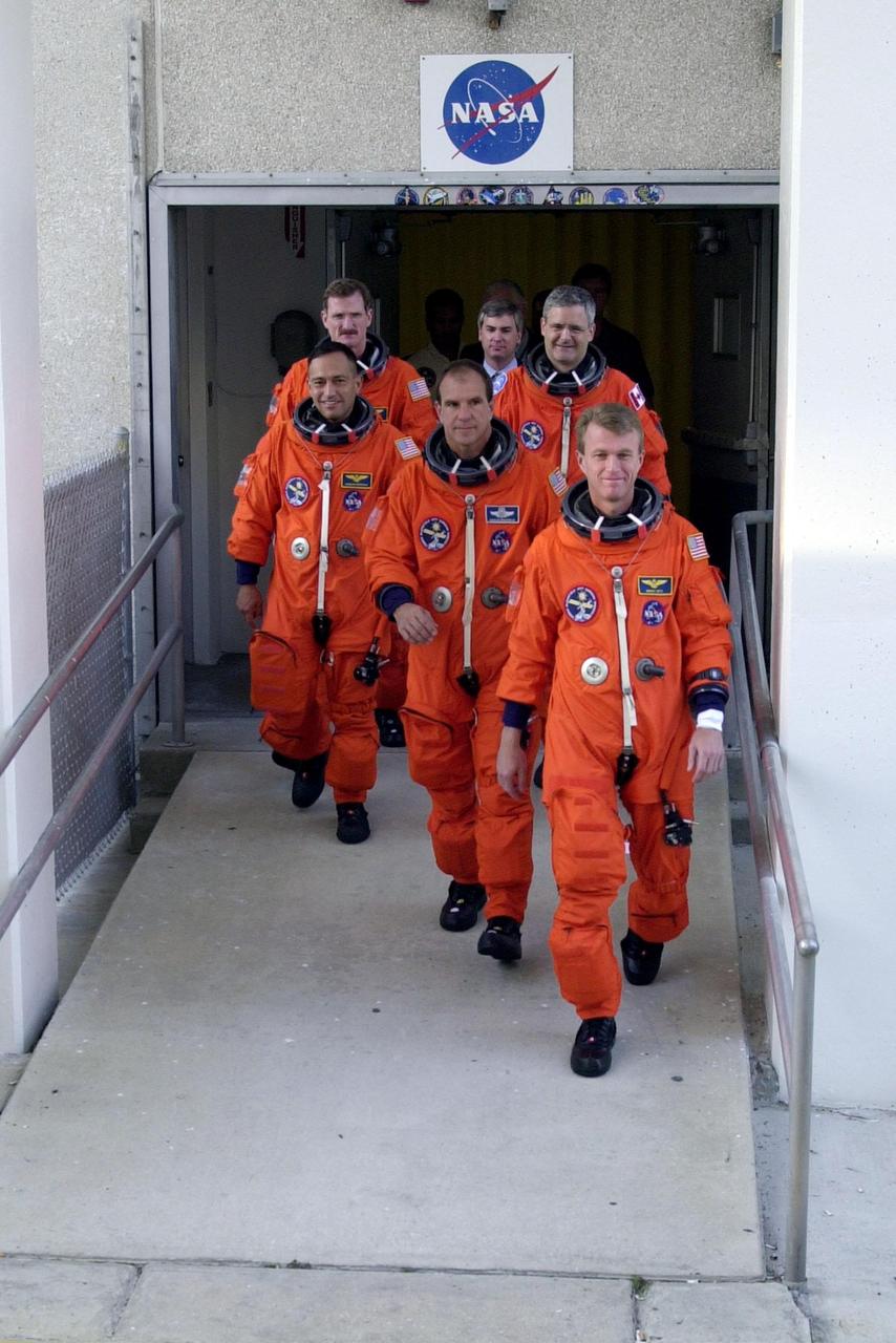
The STS-97 crew leaves the O&C Building on their way to Launch Pad 39B for a simulated launch countdown. Commander Brent Jett (right) leads the way with Pilot Mike Bloomfield behind him. Taking up the rear are (left) Mission Specialists Carlos Noriega, Joe Tanner and (right) Marc Garneau, who is with the Canadian Space Agency. The crew is taking part in Terminal Countdown Demonstration Test activities that include emergency egress training, familiarization with the payload, and the simulated launch countdown. Mission STS-97is the sixth construction flight to the International Space Station. Its payload includes the P6 Integrated Truss Structure and a photovoltaic (PV) module, with giant solar arrays that will provide power to the Station. The mission includes two spacewalks to complete the solar array connections. STS-97 is scheduled to launch Nov. 30 at about 10:05 p.m. EST
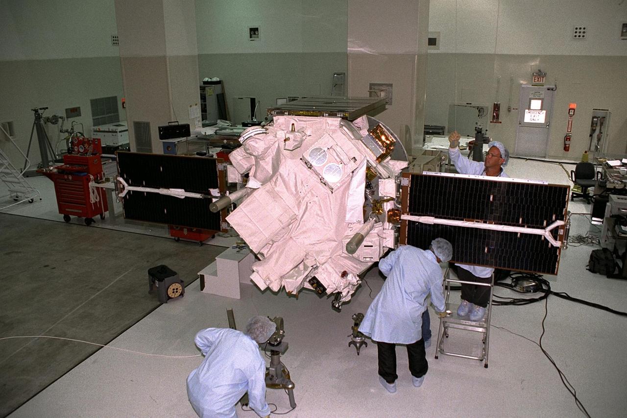
Applied Physics Laboratory engineers and technicians from Johns Hopkins University test solar array deployment of the Advanced Composition Explorer (ACE) in KSC’s Spacecraft Assembly and Encapsulation Facility-II (SAEF-II). The wire hanging from the ceiling above the black solar array panel is used for "g-negation," which takes the weight off of the panel’s hinges to simulate zero gravity, mimicking deployment in space. Scheduled for launch on a Delta II rocket from Cape Canaveral Air Station on Aug. 25, ACE will study low-energy particles of solar origin and high-energy galactic particles for a better understanding of the formation and evolution of the solar system as well as the astrophysical processes involved. The collecting power of instrumentation aboard ACE is at least 100 times more sensitive than anything previously flown to collect similar data by NASA

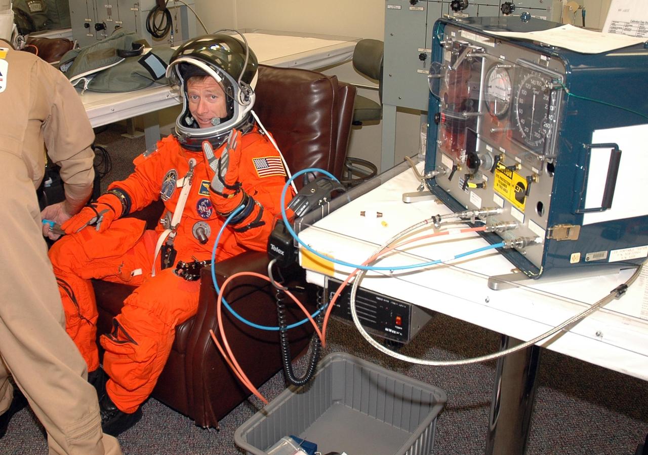
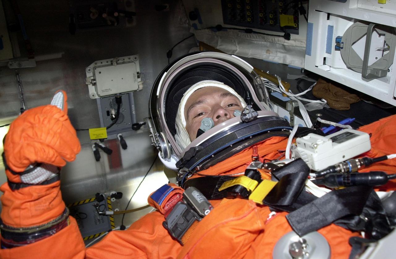
KENNEDY SPACE CENTER, FLA. - The STS-115 crew members are suiting up for their simulated launch countdown. Shown here is Mission Specialist Daniel Burbank. The mission crew is at KSC for Terminal Countdown Demonstration Test (TCDT) activities that are preparation for launch on Space Shuttle Atlantis, scheduled to take place in a window that opens Aug. 27. The TCDT has included emergency egress training as well as the simulation. During their 11-day mission to the International Space Station, the STS-115 crew will continue construction of the station and attach the payload elements, the Port 3/4 truss segment with its two large solar arrays. Photo credit: NASA/Cory Huston
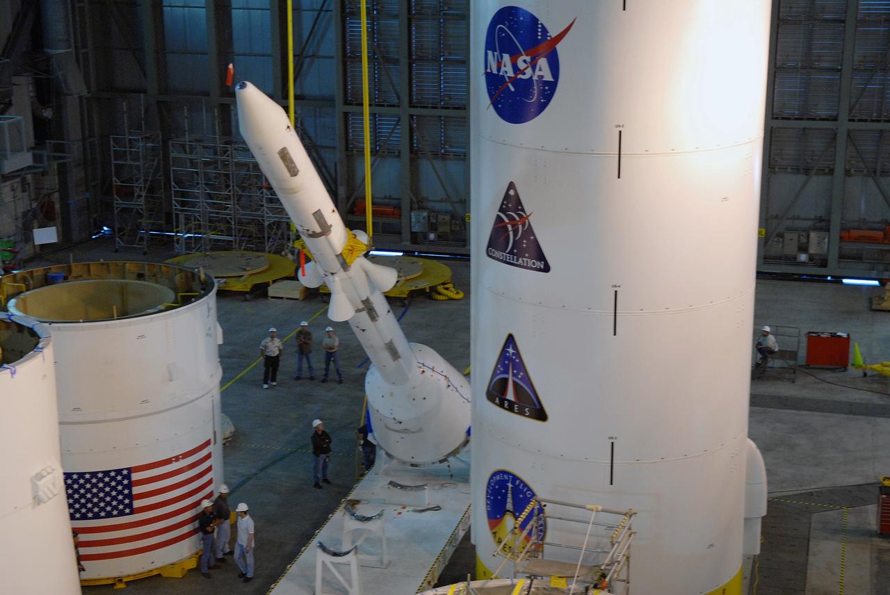
CAPE CANAVERAL, Fla. – In high bay 4 of the Vehicle Assembly Building at NASA's Kennedy Space Center in Florida, the crane raises the Ares I-X simulated launch abort system, or LAS, to a vertical position. The LAS will then be ready for assembly with the crew module simulator. Ares I-X is the flight test vehicle for the Ares I, which is part of the Constellation Program to return men to the moon and beyond. Ares I is the essential core of a safe, reliable, cost-effective space transportation system that eventually will carry crewed missions back to the moon, on to Mars and out into the solar system. Ares I-X is targeted for launch in July 2009. Photo credit: NASA/Jack Pfaller
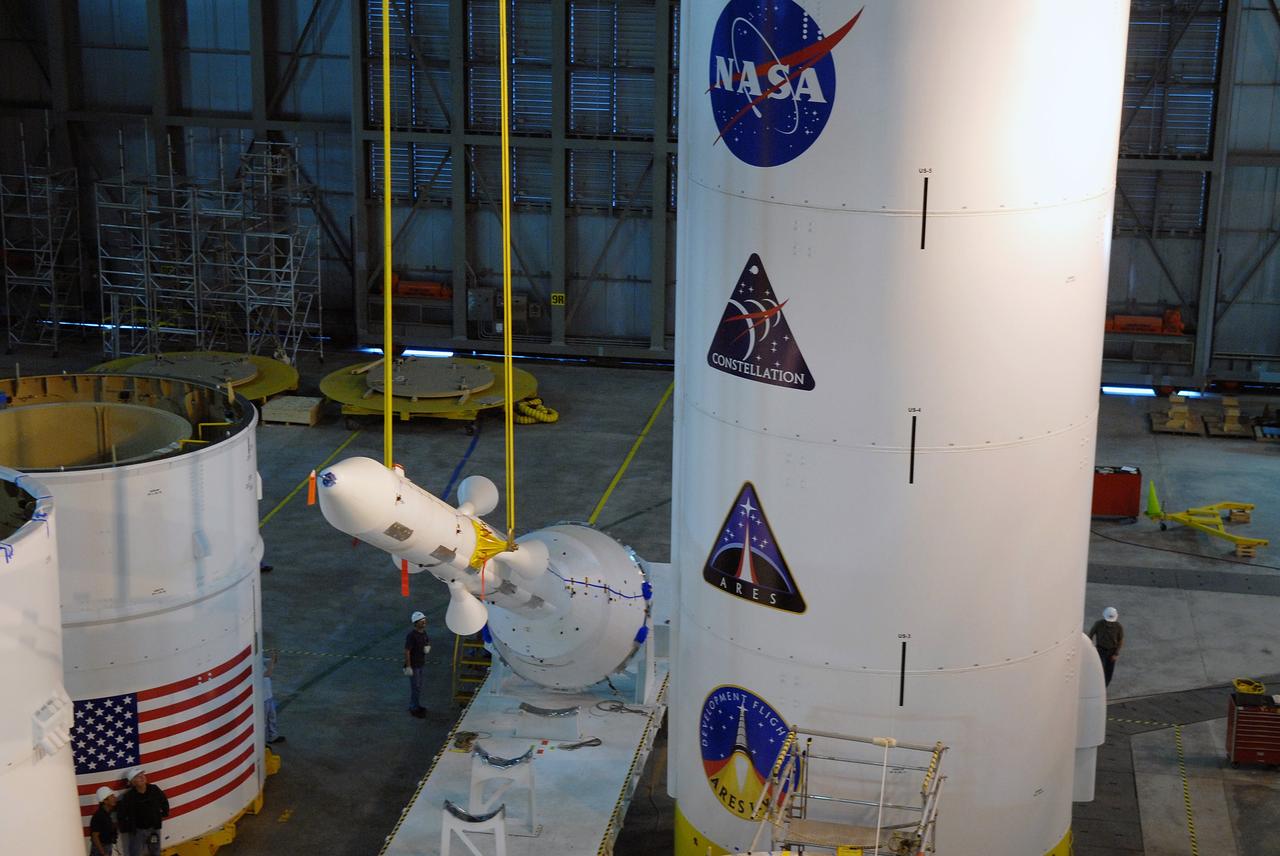
CAPE CANAVERAL, Fla. – In high bay 4 of the Vehicle Assembly Building at NASA's Kennedy Space Center in Florida, the crane begins to raise the Ares I-X simulated launch abort system, or LAS, to a vertical position. The LAS will then be ready for assembly with the crew module simulator. Ares I-X is the flight test vehicle for the Ares I, which is part of the Constellation Program to return men to the moon and beyond. Ares I is the essential core of a safe, reliable, cost-effective space transportation system that eventually will carry crewed missions back to the moon, on to Mars and out into the solar system. Ares I-X is targeted for launch in July 2009. Photo credit: NASA/Jack Pfaller
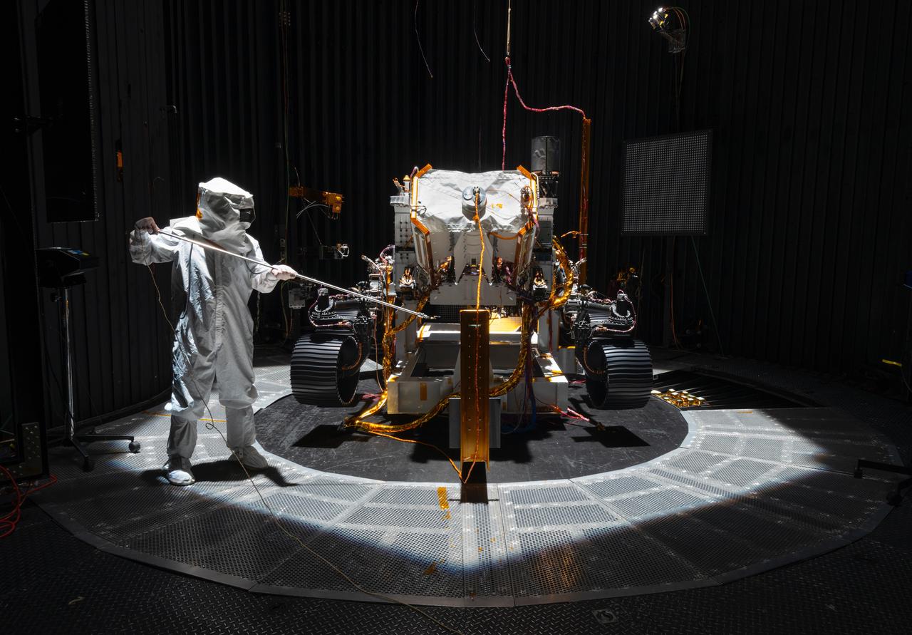
An engineer working on NASA's Mars 2020 mission uses a solar intensity probe to measure and compare the amount of artificial sunlight that reaches different portions of the rover. To simulate the Sun's rays for the test, powerful xenon lamps several floors below the chamber were illuminated, their light directed onto a mirror at the top of the chamber and reflected down on the spacecraft. The data collected during this test will be used to confirm thermal models the team has generated regarding how the Sun's rays will interact with the 2020 rover while on the surface of Mars. The image was taken on Oct. 14, 2019, in the Space Simulator Facility at NASA's Jet Propulsion Laboratory in Pasadena, California. https://photojournal.jpl.nasa.gov/catalog/PIA23469
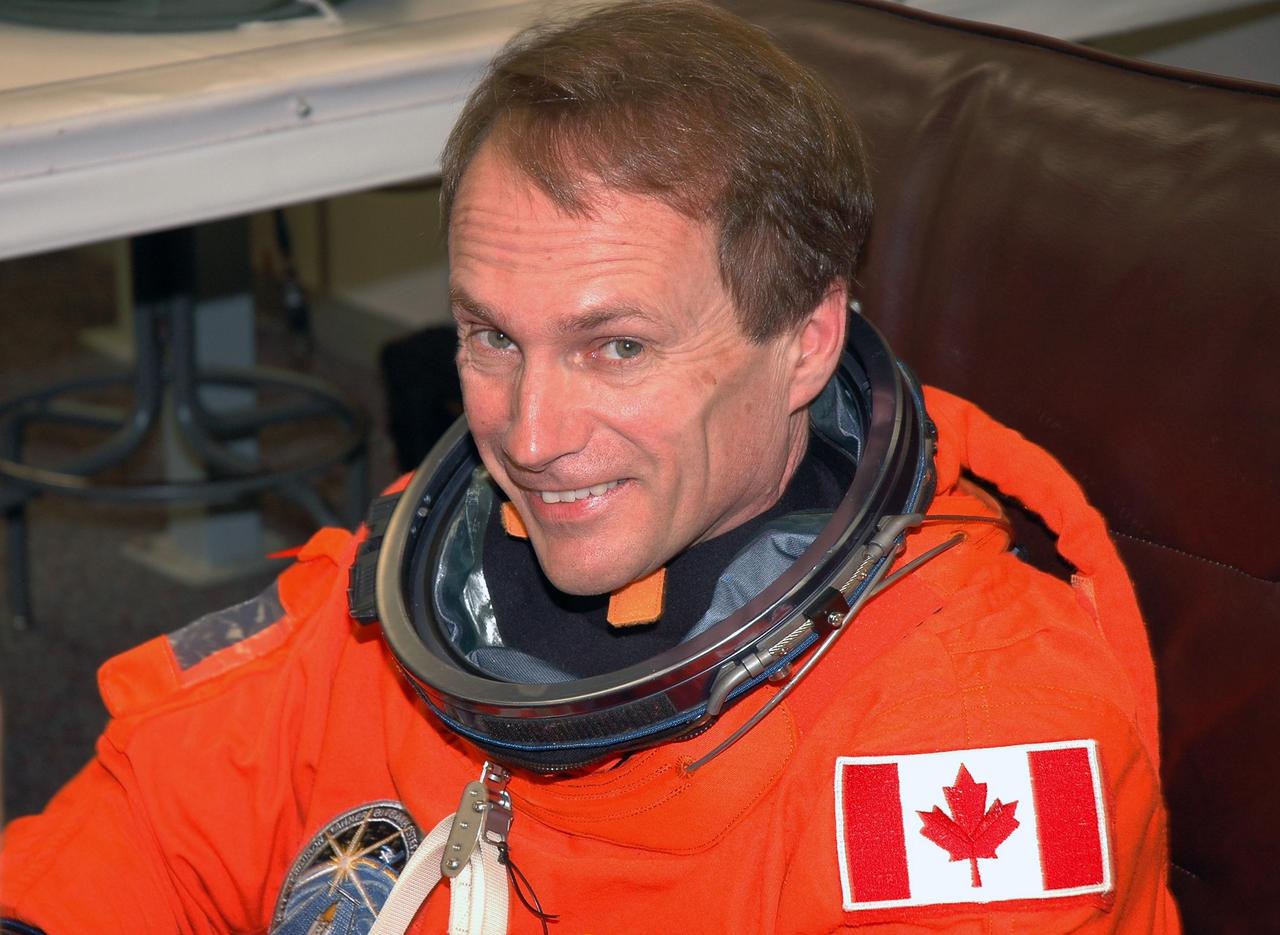
KENNEDY SPACE CENTER, FLA. - The STS-115 crew members are suiting up for their simulated launch countdown. Shown here is Mission Specialist Steven MacLean, who is with the Canadian Space Agency. The mission crew is at KSC for Terminal Countdown Demonstration Test (TCDT) activities that are preparation for launch on Space Shuttle Atlantis, scheduled to take place in a window that opens Aug. 27. The TCDT has included emergency egress training as well as the simulation. During their 11-day mission to the International Space Station, the STS-115 crew will continue construction of the station and attach the payload elements, the Port 3/4 truss segment with its two large solar arrays. Photo credit: NASA/Cory Huston
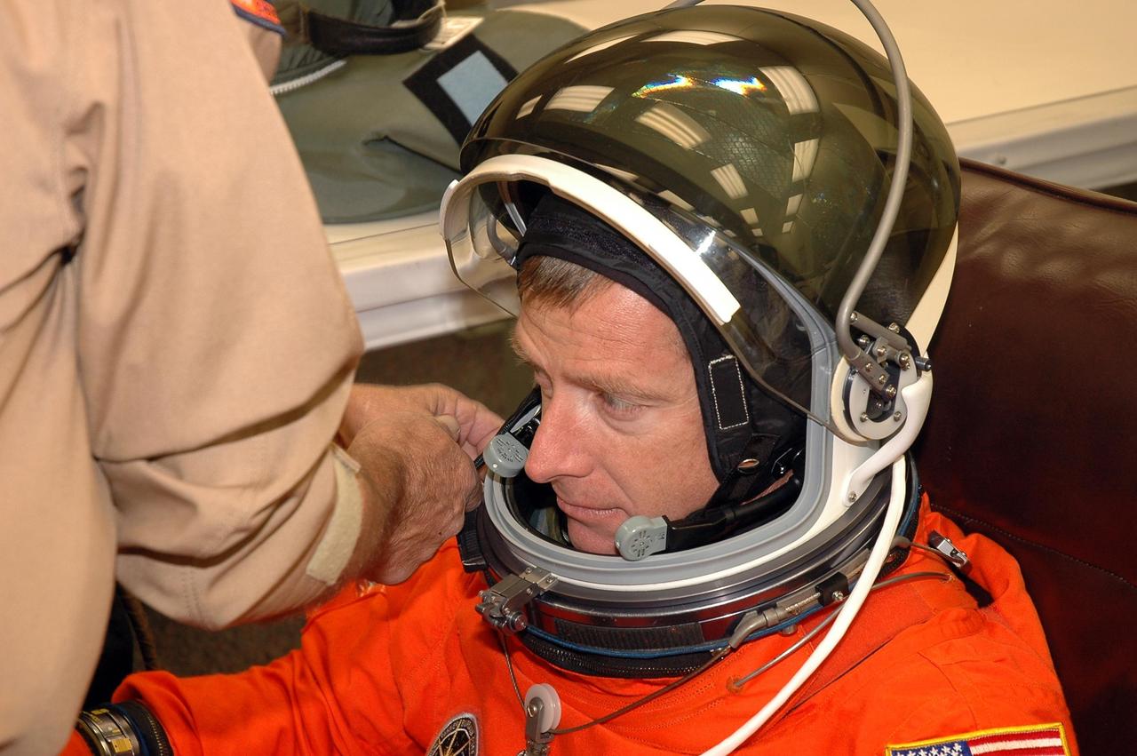
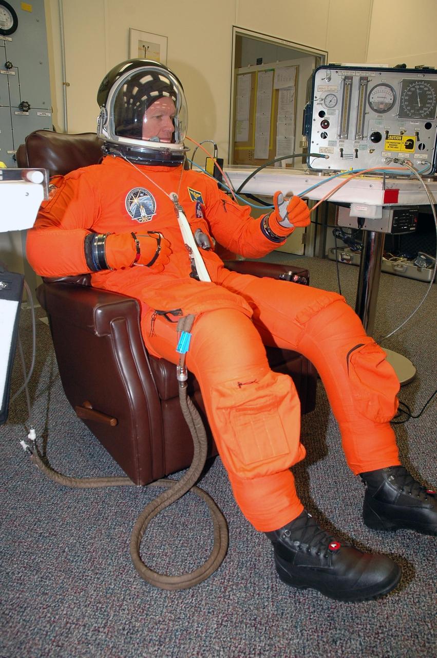
KENNEDY SPACE CENTER, FLA. - The STS-115 crew members are suiting up for their simulated launch countdown. Shown here being helped with his helmet is Pilot Christopher Ferguson. The mission crew is at KSC for Terminal Countdown Demonstration Test (TCDT) activities that are preparation for launch on Space Shuttle Atlantis, scheduled to take place in a window that opens Aug. 27. The TCDT has included emergency egress training as well as the simulation. During their 11-day mission to the International Space Station, the STS-115 crew will continue construction of the station and attach the payload elements, the Port 3/4 truss segment with its two large solar arrays. Photo credit: NASA/Cory Huston
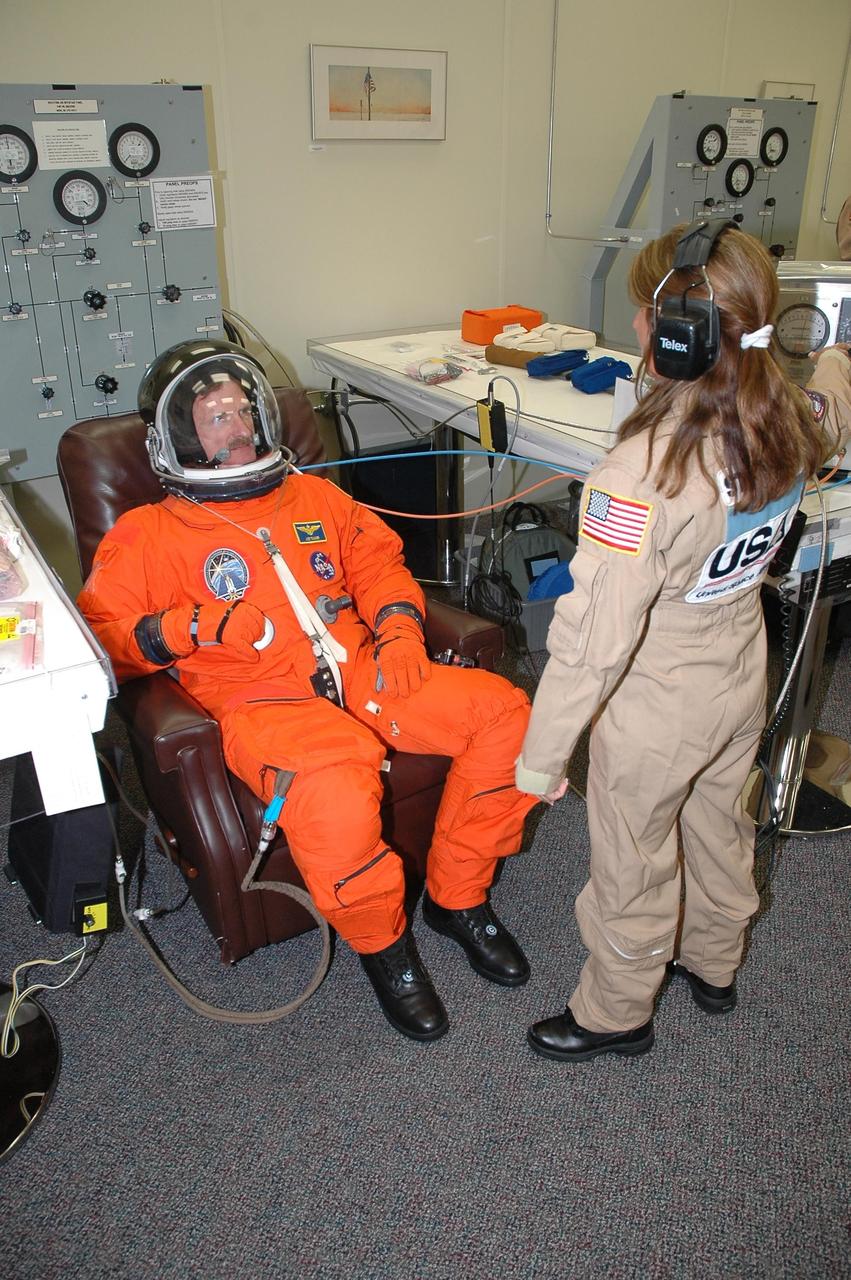
KENNEDY SPACE CENTER, FLA. - The STS-115 crew members are checking the fit of their launch and entry suits before tomorrow's simulated launch countdown. In the chair is Mission Specialist Joseph Tanner. The simulation is the culmination of Terminal Countdown Demonstration Test activities at NASA's Kennedy Space Center. The crew is getting ready for their launch on Space Shuttle Atlantis, scheduled to take place in a window that opens Aug. 27. During the 11-day mission to the International Space Station, the STS-115 crew will continue construction of the station and install their cargo, the Port 3/4 truss segment with its two large solar arrays. Photo credit: NASA/Cory Huston
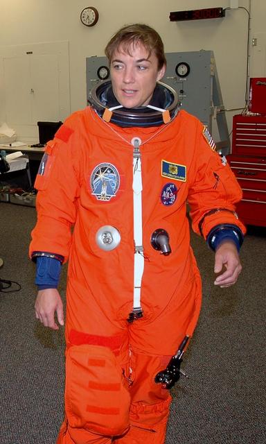
KENNEDY SPACE CENTER, FLA. - The STS-115 crew members are suiting up for their simulated launch countdown. Shown here is Mission Specialist Heidemarie Stefanyshyn-Piper. The mission crew is at KSC for Terminal Countdown Demonstration Test (TCDT) activities that are preparation for launch on Space Shuttle Atlantis, scheduled to take place in a window that opens Aug. 27. The TCDT has included emergency egress training as well as the simulation. During their 11-day mission to the International Space Station, the STS-115 crew will continue construction of the station and attach the payload elements, the Port 3/4 truss segment with its two large solar arrays. Photo credit: NASA/Cory Huston
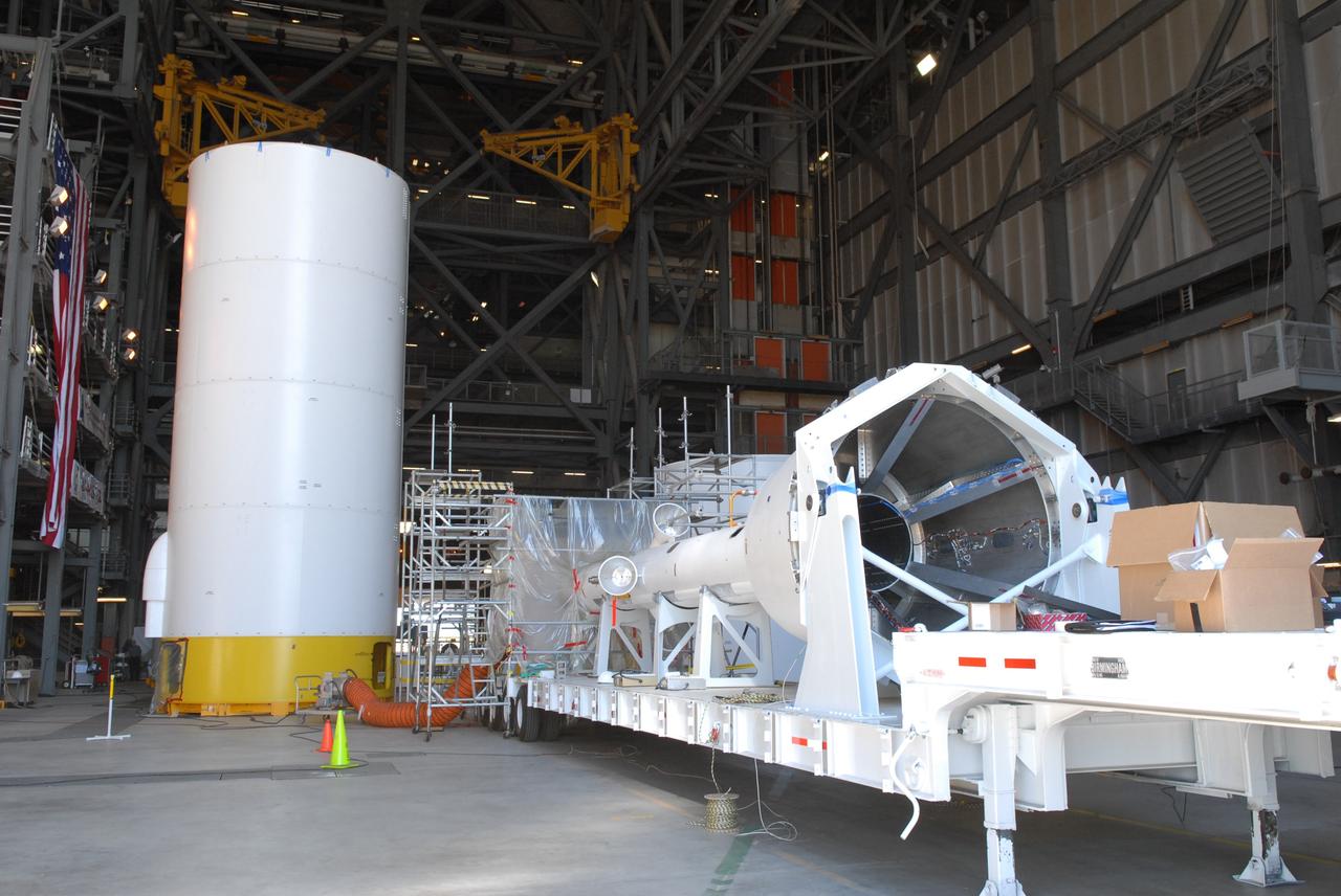
CAPE CANAVERAL, Fla. – In the transfer aisle of the Vehicle Assembly Building at NASA's Kennedy Space Center in Florida, workers monitor the conjoined forward and center segments of the fifth segment simulator for the Ares I-X as a crane lifts them toward the simulator’s aft segment. Ares I-X is the test vehicle for the Ares I, a component of the Constellation Program to return men to the moon and beyond. Ares I is the essential core of a safe, reliable, cost-effective space transportation system that eventually will carry crewed missions back to the moon, on to Mars and out into the solar system. The launch of the Ares I-X flight test is targeted for August 2009. Photo credit: NASA/Jim Grossmann

KENNEDY SPACE CENTER, FLA. - The STS-115 crew members are suiting up for their simulated launch countdown. Shown here adjusting his glove is Mission Specialist Joseph Tanner. The mission crew is at KSC for Terminal Countdown Demonstration Test (TCDT) activities that are preparation for launch on Space Shuttle Atlantis, scheduled to take place in a window that opens Aug. 27. The TCDT has included emergency egress training as well as the simulation. During their 11-day mission to the International Space Station, the STS-115 crew will continue construction of the station and attach the payload elements, the Port 3/4 truss segment with its two large solar arrays. Photo credit: NASA/Cory Huston
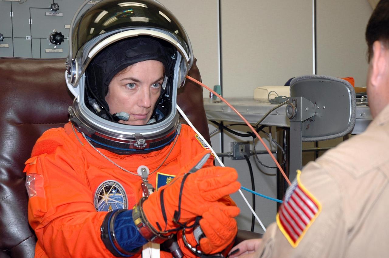
KENNEDY SPACE CENTER, FLA. - The STS-115 crew members are checking the fit of their launch and entry suits before tomorrow's simulated launch countdown. Checking her glove is Mission Specialist Heidemarie Stefanyshyn-Piper. The simulation is the culmination of Terminal Countdown Demonstration Test activities at NASA's Kennedy Space Center. The crew is getting ready for their launch on Space Shuttle Atlantis, scheduled to take place in a window that opens Aug. 27. During the 11-day mission to the International Space Station, the STS-115 crew will continue construction of the station and install their cargo, the Port 3/4 truss segment with its two large solar arrays. Photo credit: NASA/Cory Huston

KENNEDY SPACE CENTER, FLA. - The STS-115 crew members are suiting up for their simulated launch countdown. Shown here is Commander Brent Jett. The mission crew is at KSC for Terminal Countdown Demonstration Test (TCDT) activities that are preparation for launch on Space Shuttle Atlantis, scheduled to take place in a window that opens Aug. 27. The TCDT has included emergency egress training as well as the simulation. During their 11-day mission to the International Space Station, the STS-115 crew will continue construction of the station and attach the payload elements, the Port 3/4 truss segment with its two large solar arrays. Photo credit: NASA/Cory Huston
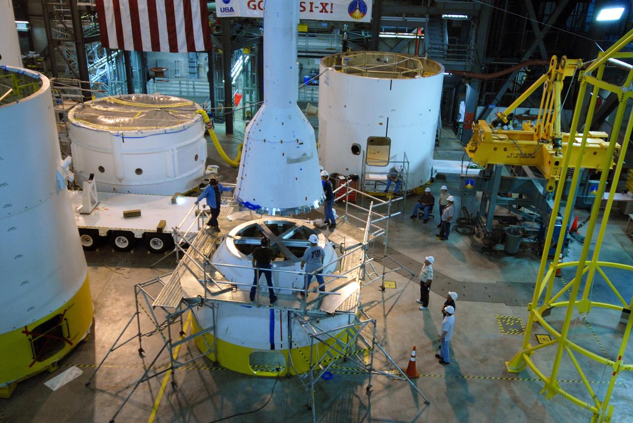
CAPE CANAVERAL, Fla. – In high bay 4 of the Vehicle Assembly Building at NASA's Kennedy Space Center in Florida, workers prepare the crane that will lift and rotate the Ares I-X simulated launch abort system (center) for assembly with the crew module simulator. Ares I-X is the flight test vehicle for the Ares I, which is part of the Constellation Program to return men to the moon and beyond. Ares I is the essential core of a safe, reliable, cost-effective space transportation system that eventually will carry crewed missions back to the moon, on to Mars and out into the solar system. Ares I-X is targeted for launch in July 2009. Photo credit: NASA/Jack Pfaller
KENNEDY SPACE CENTER, FLA. - The STS-115 crew members are suiting up for their simulated launch countdown. Shown here is Commander Brent Jett. The mission crew is at KSC for Terminal Countdown Demonstration Test (TCDT) activities that are preparation for launch on Space Shuttle Atlantis, scheduled to take place in a window that opens Aug. 27. The TCDT has included emergency egress training as well as the simulation. During their 11-day mission to the International Space Station, the STS-115 crew will continue construction of the station and attach the payload elements, the Port 3/4 truss segment with its two large solar arrays. Photo credit: NASA/Cory Huston
KENNEDY SPACE CENTER, FLA. - The STS-115 crew members are suiting up for their simulated launch countdown. Shown here being helped with his glove is Pilot Christopher Ferguson. The mission crew is at KSC for Terminal Countdown Demonstration Test (TCDT) activities that are preparation for launch on Space Shuttle Atlantis, scheduled to take place in a window that opens Aug. 27. The TCDT has included emergency egress training as well as the simulation. During their 11-day mission to the International Space Station, the STS-115 crew will continue construction of the station and attach the payload elements, the Port 3/4 truss segment with its two large solar arrays. Photo credit: NASA/Cory Huston
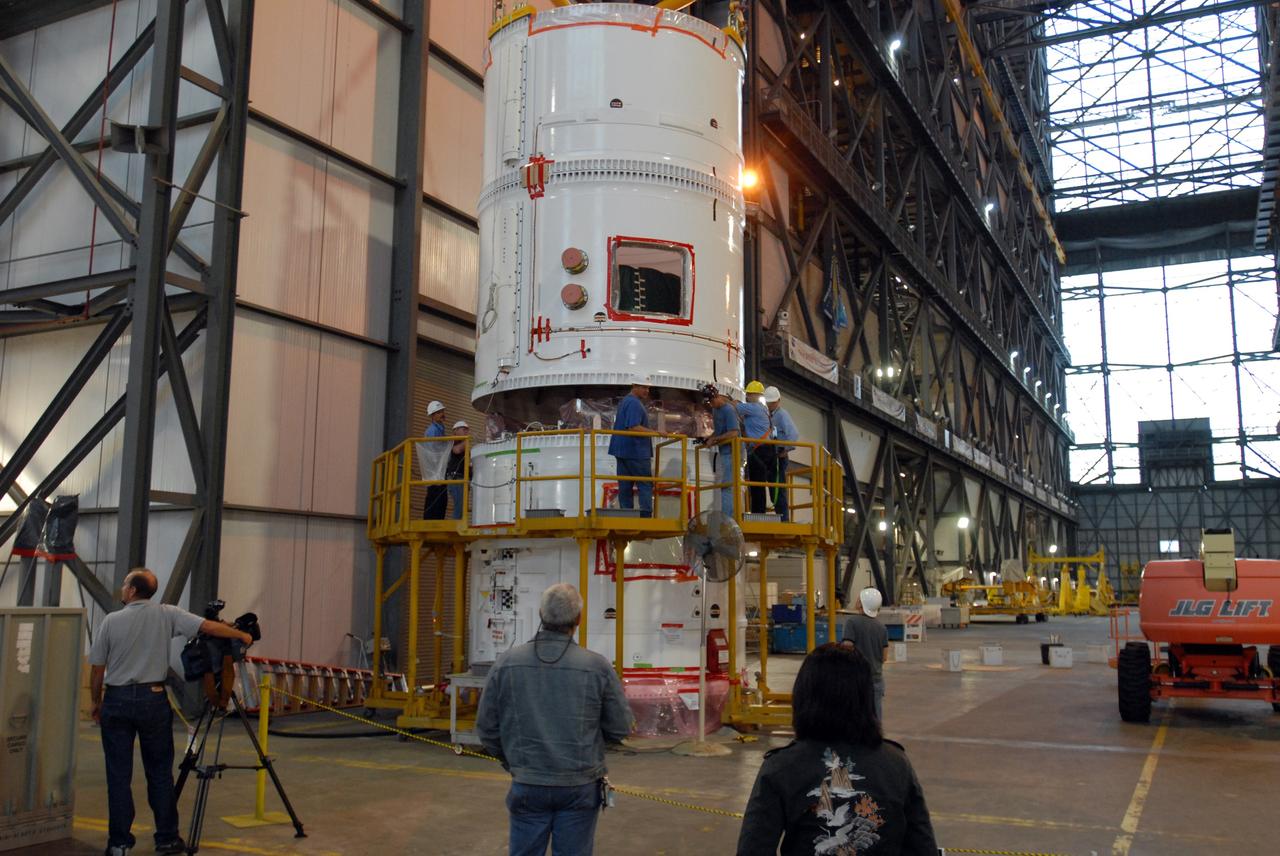
CAPE CANAVERAL, Fla. – In the transfer aisle of the Vehicle Assembly Building at NASA's Kennedy Space Center in Florida, a crane lowers the conjoined forward and center segments of the fifth segment simulator for the Ares I-X onto the simulator’s aft segment. Ares I-X is the test vehicle for the Ares I, a component of the Constellation Program to return men to the moon and beyond. Ares I is the essential core of a safe, reliable, cost-effective space transportation system that eventually will carry crewed missions back to the moon, on to Mars and out into the solar system. The launch of the Ares I-X flight test is targeted for August 2009. Photo credit: NASA/Jim Grossmann
CAPE CANAVERAL, Fla. – In the transfer aisle of the Vehicle Assembly Building at NASA's Kennedy Space Center in Florida, workers prepare to lift the conjoined forward and center segments of the fifth segment simulator for the Ares I-X. The segments will be mated to the simulator’s aft segment, at left. Ares I-X is the test vehicle for the Ares I, a component of the Constellation Program to return men to the moon and beyond. Ares I is the essential core of a safe, reliable, cost-effective space transportation system that eventually will carry crewed missions back to the moon, on to Mars and out into the solar system. The launch of the Ares I-X flight test is targeted for August 2009. Photo credit: NASA/Jim Grossmann
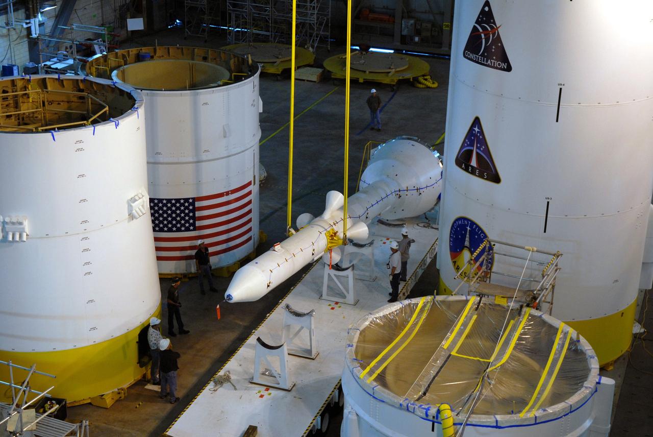
CAPE CANAVERAL, Fla. – In In high bay 4 of the Vehicle Assembly Building at NASA's Kennedy Space Center in Florida, the crane lifts the Ares I-X simulated launch abort system, or LAS, from its stand. The LAS will be rotated to vertical for assembly with the crew module simulator. Ares I-X is the flight test vehicle for the Ares I, which is part of the Constellation Program to return men to the moon and beyond. Ares I is the essential core of a safe, reliable, cost-effective space transportation system that eventually will carry crewed missions back to the moon, on to Mars and out into the solar system. Ares I-X is targeted for launch in July 2009. Photo credit: NASA/Jack Pfaller
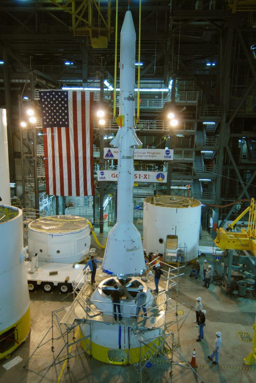
CAPE CANAVERAL, Fla. – In high bay 4 of the Vehicle Assembly Building at NASA's Kennedy Space Center in Florida, workers keep close watch on the Ares I-X simulated launch abort system, or LAS, as it is lowered toward the crew module simulator. Ares I-X is the flight test vehicle for the Ares I, which is part of the Constellation Program to return men to the moon and beyond. Ares I is the essential core of a safe, reliable, cost-effective space transportation system that eventually will carry crewed missions back to the moon, on to Mars and out into the solar system. Ares I-X is targeted for launch in July 2009. Photo credit: NASA/Jack Pfaller
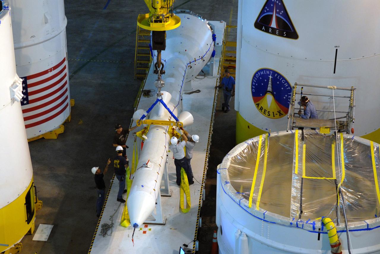
CAPE CANAVERAL, Fla. – In high bay 4 of the Vehicle Assembly Building at NASA's Kennedy Space Center in Florida, workers place a crane and straps on the Ares I-X simulated launch abort system to lift and rotate it for assembly with the crew module simulator. Ares I-X is the flight test vehicle for the Ares I, which is part of the Constellation Program to return men to the moon and beyond. Ares I is the essential core of a safe, reliable, cost-effective space transportation system that eventually will carry crewed missions back to the moon, on to Mars and out into the solar system. Ares I-X is targeted for launch in July 2009. Photo credit: NASA/Jack Pfaller
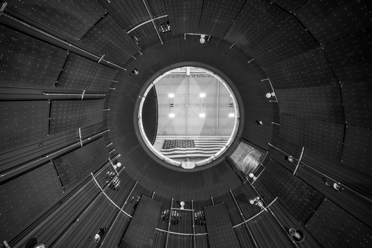
NASA’s In-Space Propulsion Facility located at Neil Armstrong Test Facility in Sandusky Ohio is the world’s only high altitude test facility capable of full-scale rocket engine and launch vehicle system level tests. The facility supports mission profile thermal vacuum simulation and engine firing. The engine or vehicle can be exposed for indefinite periods to low ambient pressures, low-background temperatures, and dynamic solar heating, simulating the environment the hardware will encounter during orbital or interplanetary travel. This is a view from inside the chamber looking up toward the American flag. Photo Credit: (NASA/Jordan Salkin)
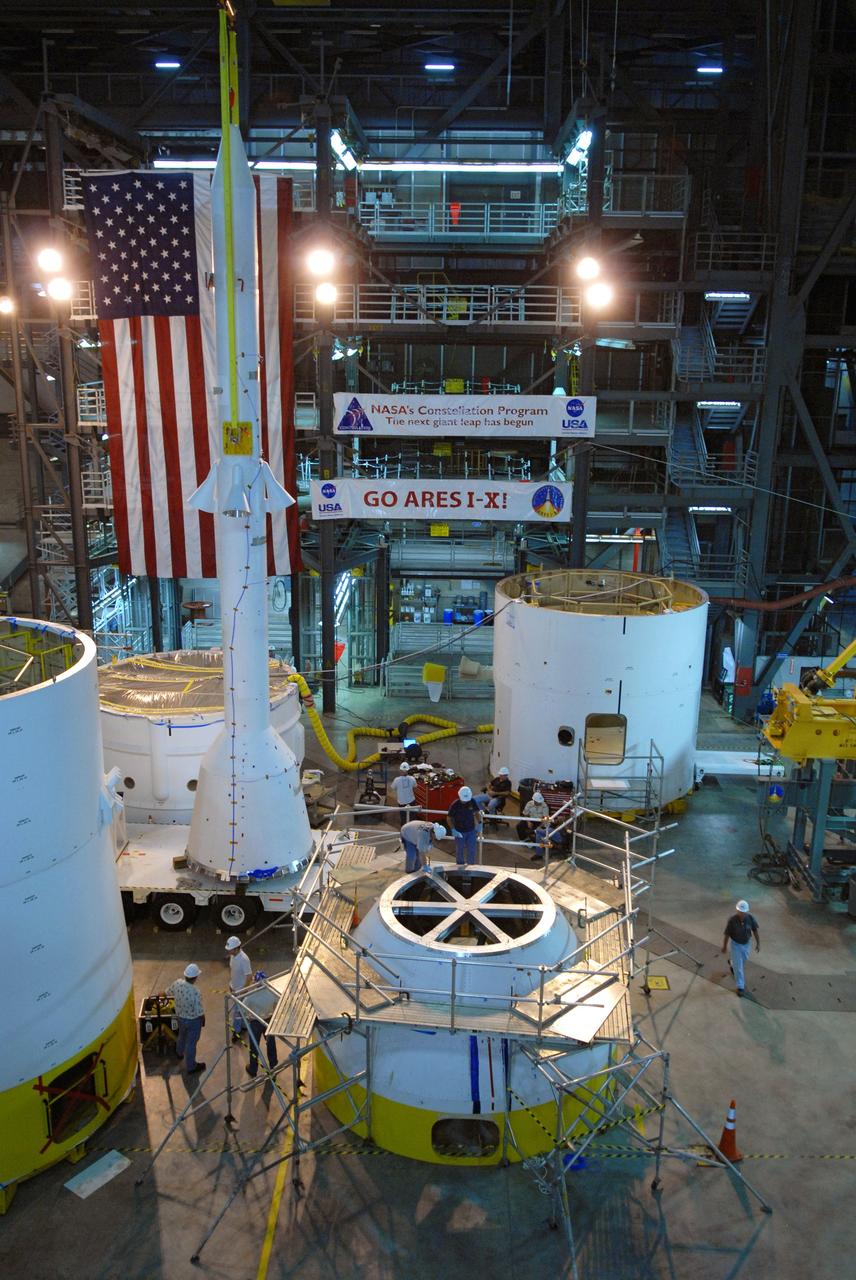
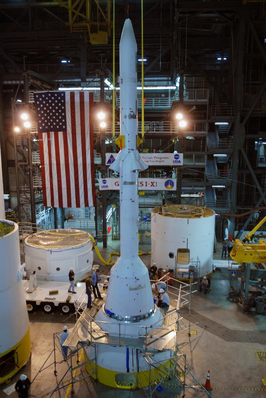
CAPE CANAVERAL, Fla. – Simulator segments of the Ares I-X are on display for the media in the Vehicle Assembly Building at NASA's Kennedy Space Center in Florida. At left are several stacked segments. At right is the launch abort system simulator. The I-X flight will provide NASA an early opportunity to test and prove hardware, facilities and ground operations associated with Ares I, part of the Constellation Program to return men to the moon and beyond. Ares I is the essential core of a safe, reliable, cost-effective space transportation system that eventually will carry crewed missions back to the moon, on to Mars and out into the solar system. Photo credit: NASA/Jack Pfaller
CAPE CANAVERAL, Fla. – In high bay 4 of the Vehicle Assembly Building at NASA's Kennedy Space Center in Florida, workers keep close watch on the Ares I-X simulated launch abort system, or LAS, as it is lowered toward the crew module simulator. Ares I-X is the flight test vehicle for the Ares I, which is part of the Constellation Program to return men to the moon and beyond. Ares I is the essential core of a safe, reliable, cost-effective space transportation system that eventually will carry crewed missions back to the moon, on to Mars and out into the solar system. Ares I-X is targeted for launch in July 2009. Photo credit: NASA/Jack Pfaller
CAPE CANAVERAL, Fla. – In the transfer aisle of the Vehicle Assembly Building at NASA's Kennedy Space Center in Florida, the conjoined forward and center segments of the fifth segment simulator for the Ares I-X is attached to a crane prior to lifting operations. The segments will be mated to the simulator’s aft segment. Ares I-X is the test vehicle for the Ares I, a component of the Constellation Program to return men to the moon and beyond. Ares I is the essential core of a safe, reliable, cost-effective space transportation system that eventually will carry crewed missions back to the moon, on to Mars and out into the solar system. The launch of the Ares I-X flight test is targeted for August 2009. Photo credit: NASA/Jim Grossmann
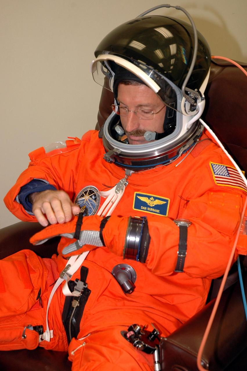
KENNEDY SPACE CENTER, FLA. - The STS-115 crew members are suiting up for their simulated launch countdown. Shown Shown here is Mission Specialist Daniel Burbank. The mission crew is at KSC for Terminal Countdown Demonstration Test (TCDT) activities that are preparation for launch on Space Shuttle Atlantis, scheduled to take place in a window that opens Aug. 27. The TCDT has included emergency egress training as well as the simulation. During their 11-day mission to the International Space Station, the STS-115 crew will continue construction of the station and attach the payload elements, the Port 3/4 truss segment with its two large solar arrays. Photo credit: NASA/Cory Huston
CAPE CANAVERAL, Fla. – In high bay 4 of the Vehicle Assembly Building at NASA's Kennedy Space Center in Florida, the Ares I-X simulated launch abort system, or LAS, (left of center) is being moved to the crew module simulator (center) for assembly. Ares I-X is the flight test vehicle for the Ares I, which is part of the Constellation Program to return men to the moon and beyond. Ares I is the essential core of a safe, reliable, cost-effective space transportation system that eventually will carry crewed missions back to the moon, on to Mars and out into the solar system. Ares I-X is targeted for launch in July 2009. Photo credit: NASA/Jack Pfaller
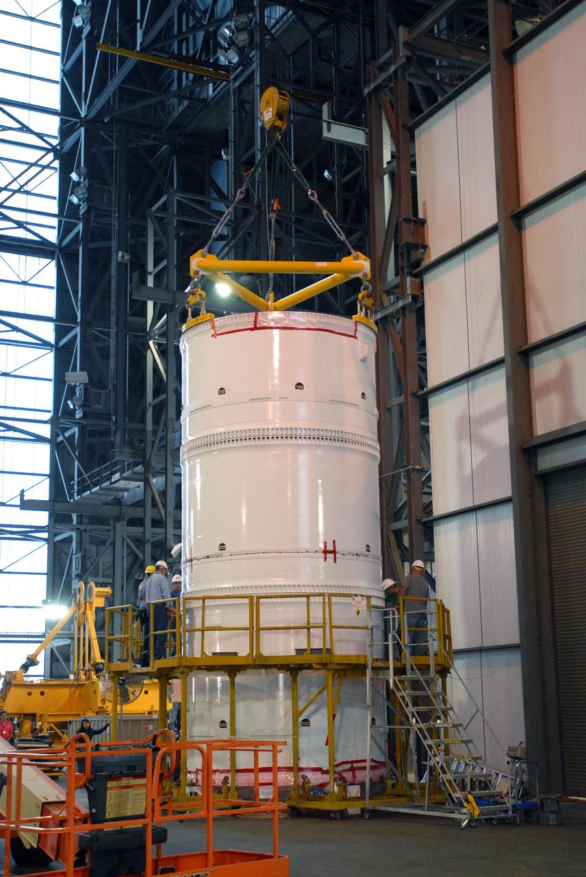
CAPE CANAVERAL, Fla. – In the transfer aisle of the Vehicle Assembly Building at NASA's Kennedy Space Center in Florida, the conjoined forward and center segments of the fifth segment simulator for the Ares I-X is secured to the simulator’s aft segment. Ares I-X is the test vehicle for the Ares I, a component of the Constellation Program to return men to the moon and beyond. Ares I is the essential core of a safe, reliable, cost-effective space transportation system that eventually will carry crewed missions back to the moon, on to Mars and out into the solar system. The launch of the Ares I-X flight test is targeted for August 2009. Photo credit: NASA/Jim Grossmann
CAPE CANAVERAL, Fla. – In the transfer aisle of the Vehicle Assembly Building at NASA's Kennedy Space Center in Florida, a crane lifts the conjoined forward and center segments of the fifth segment simulator for the Ares I-X. The segments will be mated to the simulator’s aft segment, at left. Ares I-X is the test vehicle for the Ares I, a component of the Constellation Program to return men to the moon and beyond. Ares I is the essential core of a safe, reliable, cost-effective space transportation system that eventually will carry crewed missions back to the moon, on to Mars and out into the solar system. The launch of the Ares I-X flight test is targeted for August 2009. Photo credit: NASA/Jim Grossmann
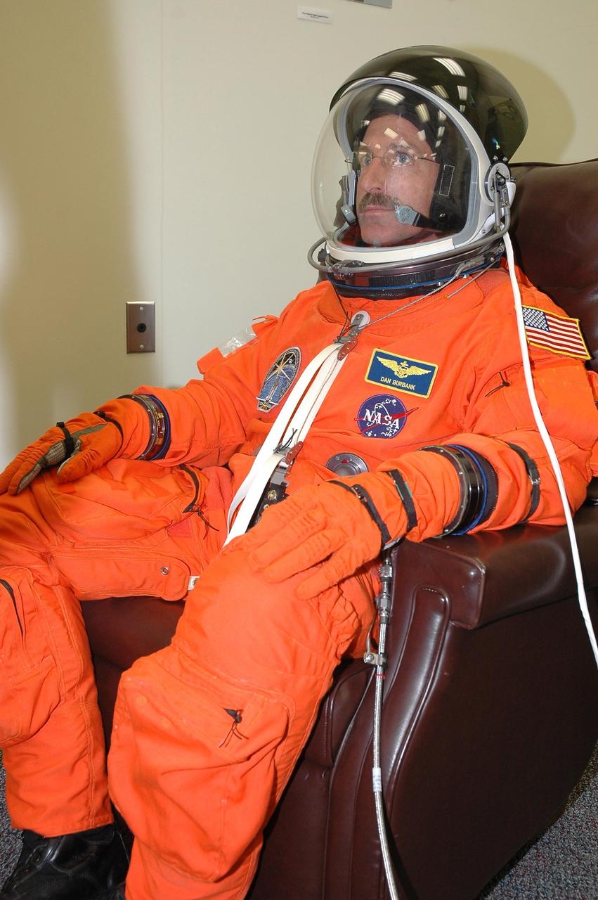
KENNEDY SPACE CENTER, FLA. - The STS-115 crew members are checking the fit of their launch and entry suits before tomorrow's simulated launch countdown. In the chair is Mission Specialist Daniel Burbank. The simulation is the culmination of Terminal Countdown Demonstration Test activities at NASA's Kennedy Space Center. The crew is getting ready for their launch on Space Shuttle Atlantis, scheduled to take place in a window that opens Aug. 27. During the 11-day mission to the International Space Station, the STS-115 crew will continue construction of the station and install their cargo, the Port 3/4 truss segment with its two large solar arrays. Photo credit: NASA/Cory Huston
CAPE CANAVERAL, Fla. – In high bay 4 of the Vehicle Assembly Building at NASA's Kennedy Space Center in Florida, workers keep close watch on the Ares I-X simulated launch abort system, or LAS, as it is lowered onto the crew module simulator for assembly. Ares I-X is the flight test vehicle for the Ares I, which is part of the Constellation Program to return men to the moon and beyond. Ares I is the essential core of a safe, reliable, cost-effective space transportation system that eventually will carry crewed missions back to the moon, on to Mars and out into the solar system. Ares I-X is targeted for launch in July 2009. Photo credit: NASA/Jack Pfaller
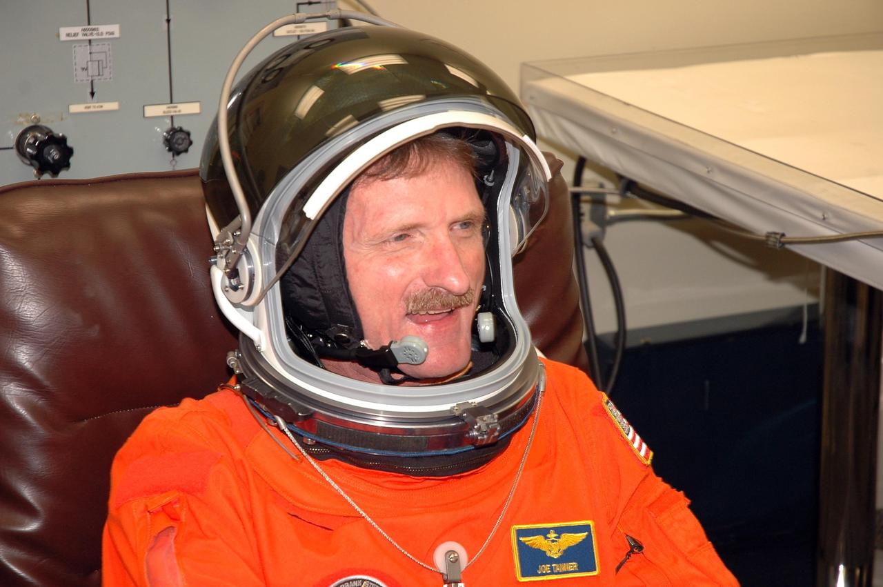
KENNEDY SPACE CENTER, FLA. - The STS-115 crew members are suiting up for their simulated launch countdown. Shown here is Mission Specialist Joseph Tanner. The mission crew is at KSC for Terminal Countdown Demonstration Test (TCDT) activities that are preparation for launch on Space Shuttle Atlantis, scheduled to take place in a window that opens Aug. 27. The TCDT has included emergency egress training as well as the simulation. During their 11-day mission to the International Space Station, the STS-115 crew will continue construction of the station and attach the payload elements, the Port 3/4 truss segment with its two large solar arrays. Photo credit: NASA/Cory Huston
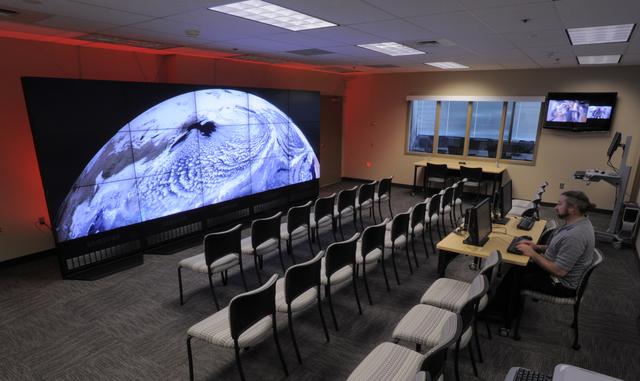
The NASA Center for Climate Simulation (NCCS) Data Exploration Theater features a 17- by 6-foot multi-screen visualization wall for engaging visitors and scientists with high-definition movies of simulation results. Here, the wall displays a 3.5-kilometer-resolution global simulation that captures numerous cloud types at groundbreaking fidelity. Credit: NASA/Pat Izzo To learn more about NCCS go to: <a href="http://www.nasa.gov/topics/earth/features/climate-sim-center.html" rel="nofollow">www.nasa.gov/topics/earth/features/climate-sim-center.html</a> NASA Goddard Space Flight Center is home to the nation's largest organization of combined scientists, engineers and technologists that build spacecraft, instruments and new technology to study the Earth, the sun, our solar system, and the universe.
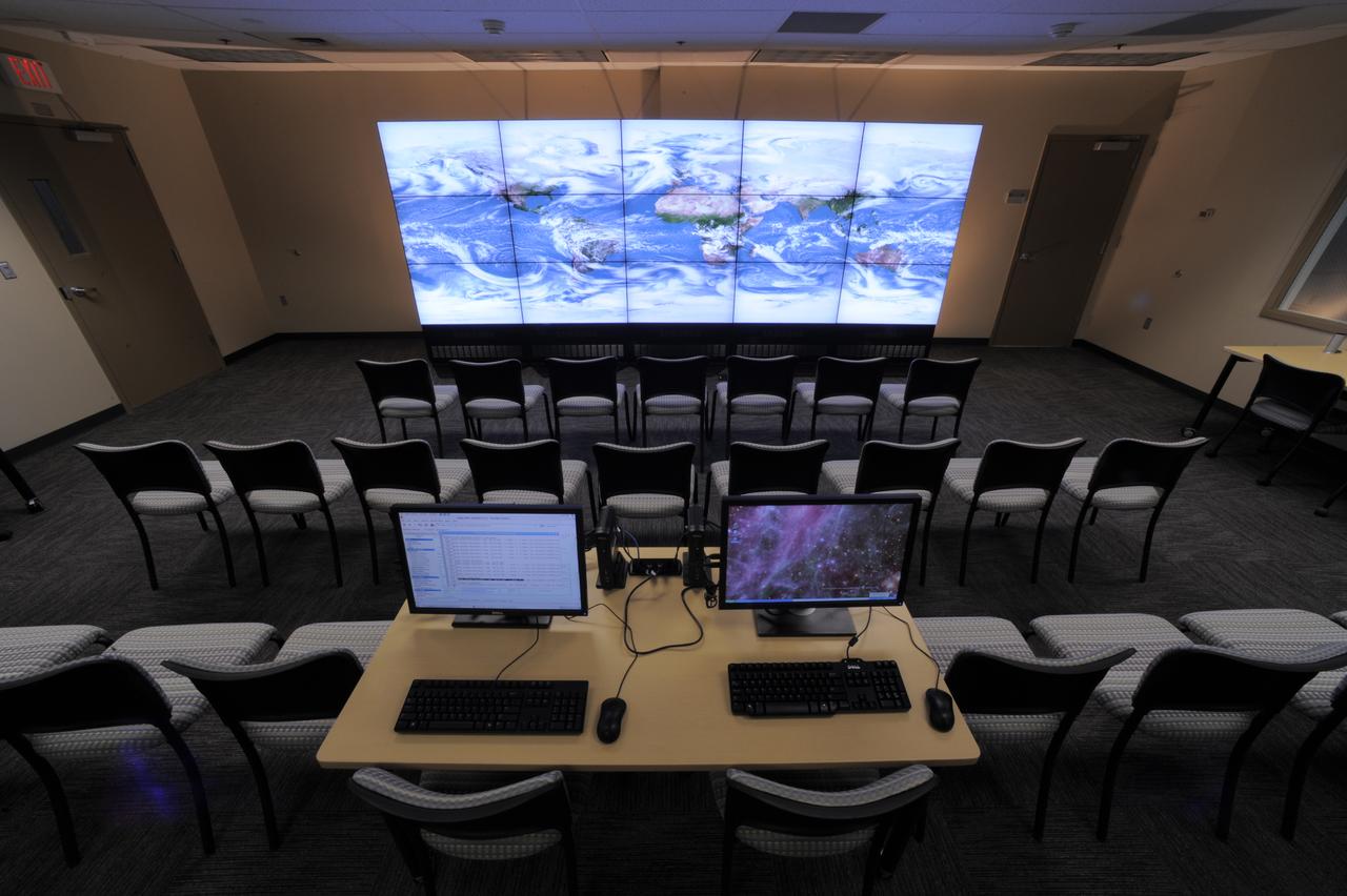
The NASA Center for Climate Simulation (NCCS) Data Exploration Theater features a 17- by 6-foot multi-screen visualization wall for engaging visitors and scientists with high-definition movies of simulation results. Here, the wall displays a 5-kilometer-resolution global simulation that captures numerous cloud types at groundbreaking fidelity. Credit: NASA/Pat Izzo To learn more about NCCS go to: <a href="http://www.nasa.gov/topics/earth/features/climate-sim-center.html" rel="nofollow">www.nasa.gov/topics/earth/features/climate-sim-center.html</a> NASA Goddard Space Flight Center is home to the nation's largest organization of combined scientists, engineers and technologists that build spacecraft, instruments and new technology to study the Earth, the sun, our solar system, and the universe.
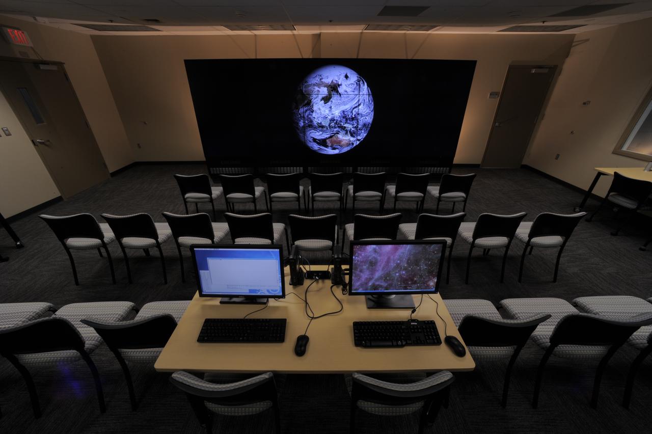
The NASA Center for Climate Simulation (NCCS) Data Exploration Theater features a 17- by 6-foot multi-screen visualization wall for engaging visitors and scientists with high-definition movies of simulation results. Here, the wall displays a 3.5-kilometer-resolution global simulation that captures numerous cloud types at groundbreaking fidelity. Credit: NASA/Pat Izzo To learn more about NCCS go to: <a href="http://www.nasa.gov/topics/earth/features/climate-sim-center.html" rel="nofollow">www.nasa.gov/topics/earth/features/climate-sim-center.html</a> NASA Goddard Space Flight Center is home to the nation's largest organization of combined scientists, engineers and technologists that build spacecraft, instruments and new technology to study the Earth, the sun, our solar system, and the universe.
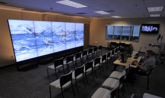
The NASA Center for Climate Simulation (NCCS) Data Exploration Theater features a 17- by 6-foot multi-screen visualization wall for engaging visitors and scientists with high-definition movies of simulation results. Here, the wall displays a 5-kilometer-resolution global simulation that captures numerous cloud types at groundbreaking fidelity. Credit: NASA/Pat Izzo To learn more about NCCS go to: <a href="http://www.nasa.gov/topics/earth/features/climate-sim-center.html" rel="nofollow">www.nasa.gov/topics/earth/features/climate-sim-center.html</a> NASA Goddard Space Flight Center is home to the nation's largest organization of combined scientists, engineers and technologists that build spacecraft, instruments and new technology to study the Earth, the sun, our solar system, and the universe.
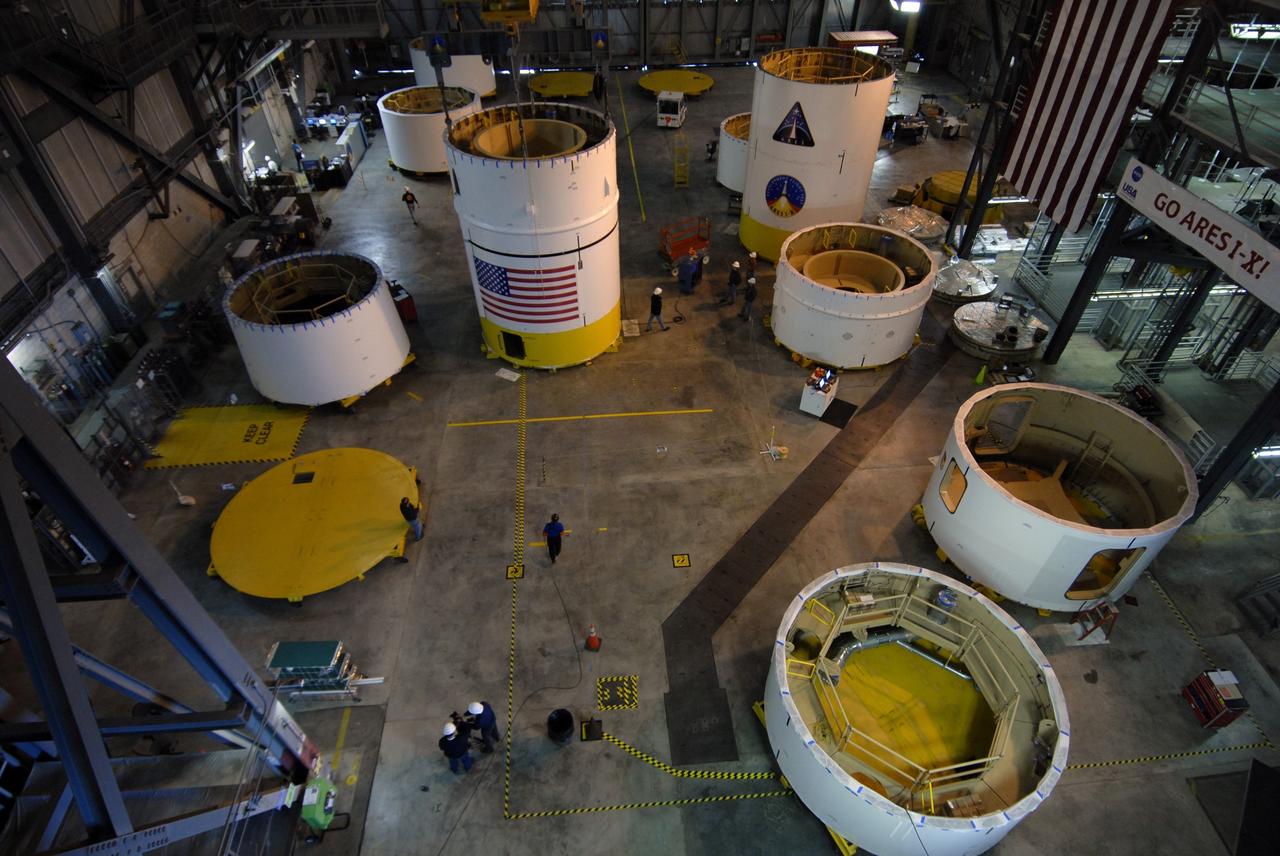
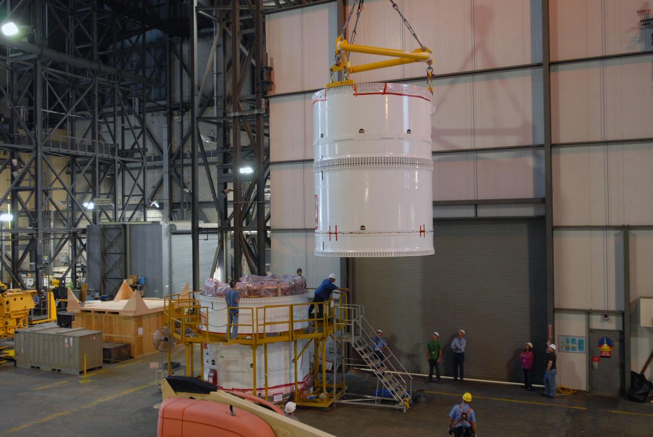
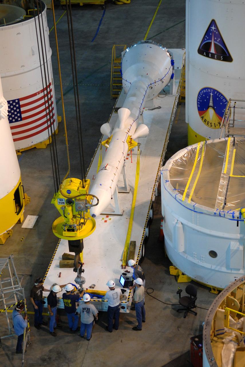
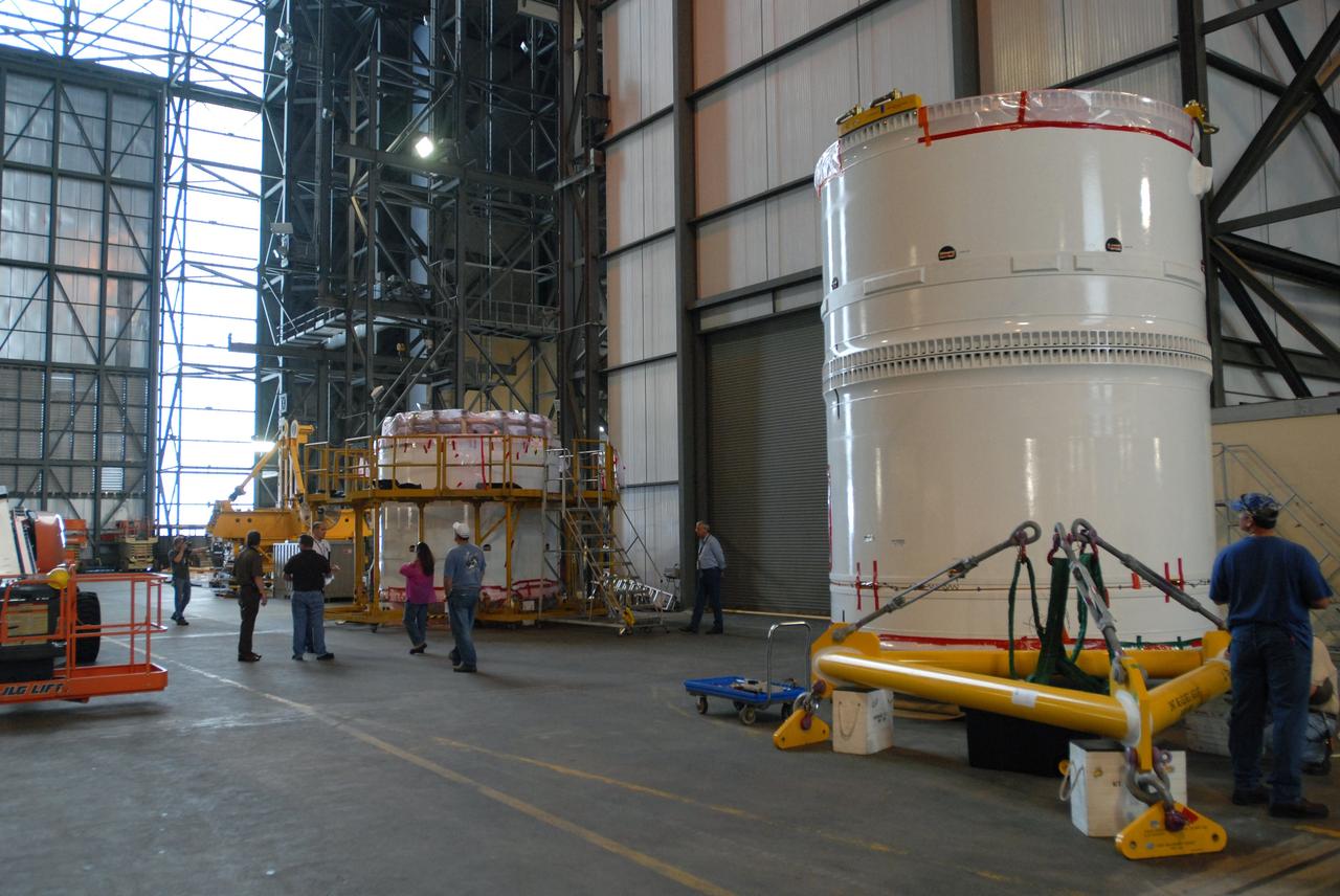
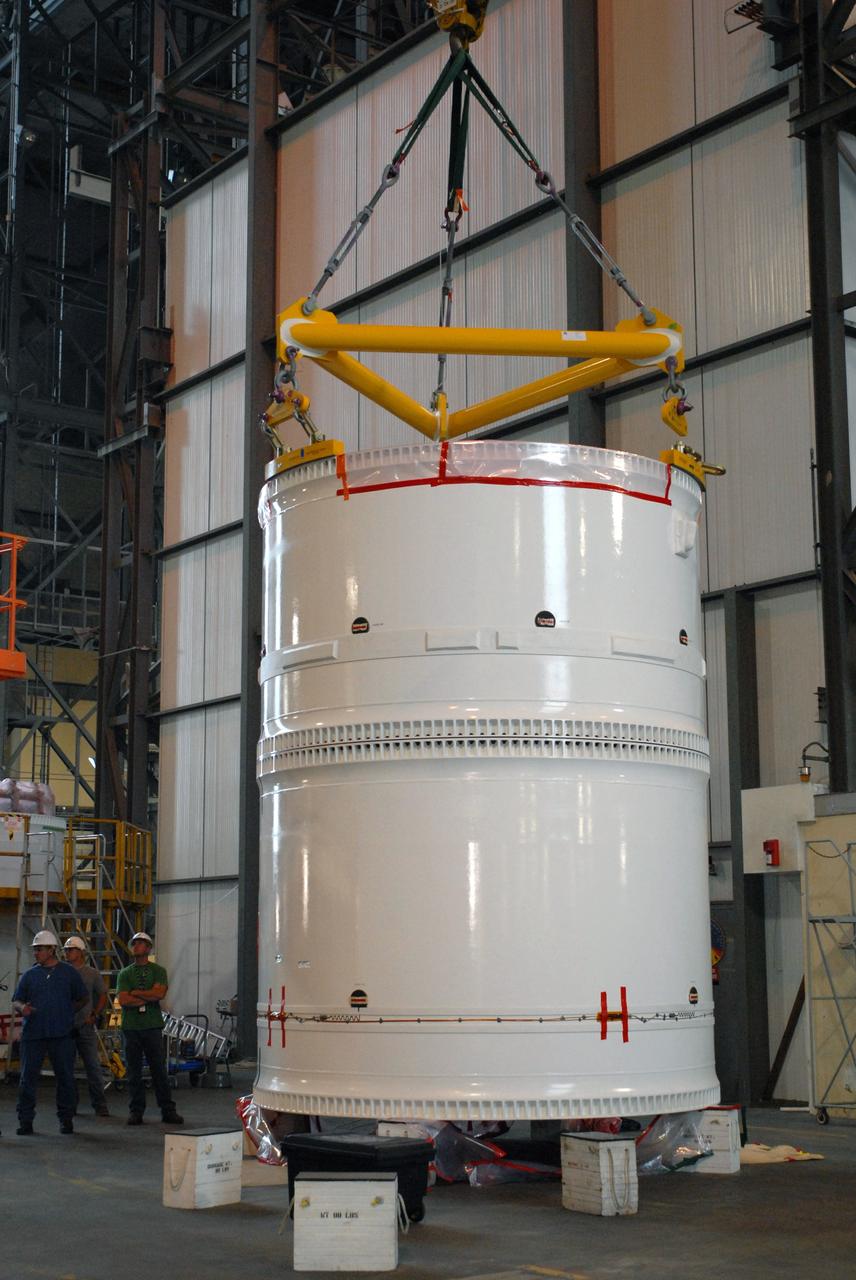
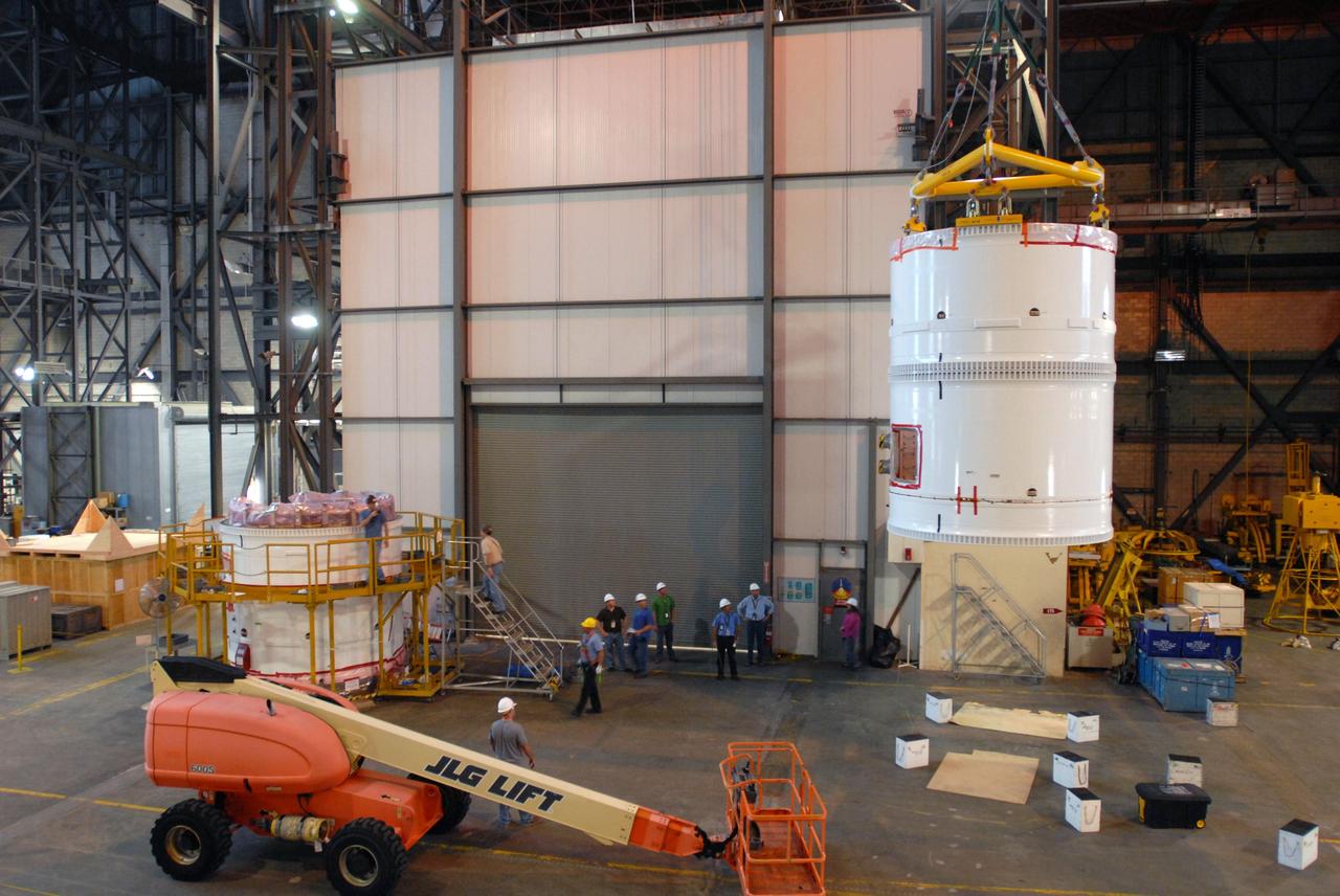
CAPE CANAVERAL, Fla. -- The upper stage simulator segments are positioned across the floor of the Vehicle Assembly Building's high bay 4 at NASA's Kennedy Space Center in Florida. Four of the segments are already stacked. The upper stage simulator will be used in the test flight identified as Ares I-X in 2009. Ares I-X is the test vehicle for the Ares I, which is part of the Constellation Program to return men to the moon and beyond. Ares I is the essential core of a safe, reliable, cost-effective space transportation system that eventually will carry crewed missions back to the moon, on to Mars and out into the solar system. Ares I may also use its 25-ton payload capacity to deliver resources and supplies to the International Space Station, or to "park" payloads in orbit for retrieval by other spacecraft bound for the moon or other destinations. The upper stage simulator comprises 11 segments, each approximately 18 feet in diameter. The simulator segments will simulate the mass and the outer mold line and will be more than 100 feet of the total vehicle height of 327 feet. Photo credit: NASA/Jack Pfaller
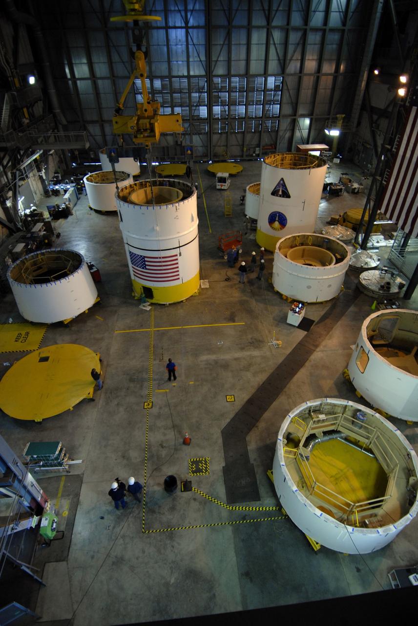
CAPE CANAVERAL, Fla. -- The upper stage simulator segments are positioned across the floor of the Vehicle Assembly Building's high bay 4 at NASA's Kennedy Space Center in Florida. Four of the segments are already stacked. The upper stage simulator will be used in the test flight identified as Ares I-X in 2009. Ares I-X is the test vehicle for the Ares I, which is part of the Constellation Program to return men to the moon and beyond. Ares I is the essential core of a safe, reliable, cost-effective space transportation system that eventually will carry crewed missions back to the moon, on to Mars and out into the solar system. Ares I may also use its 25-ton payload capacity to deliver resources and supplies to the International Space Station, or to "park" payloads in orbit for retrieval by other spacecraft bound for the moon or other destinations. The upper stage simulator comprises 11 segments, each approximately 18 feet in diameter. The simulator segments will simulate the mass and the outer mold line and will be more than 100 feet of the total vehicle height of 327 feet. Photo credit: NASA/Jack Pfaller
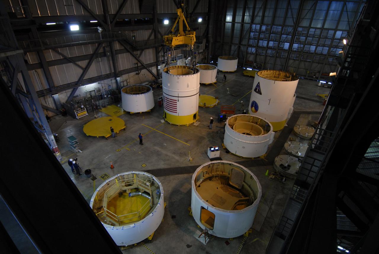
CAPE CANAVERAL, Fla. -- The upper stage simulator segments are positioned across the floor of the Vehicle Assembly Building's high bay 4 at NASA's Kennedy Space Center in Florida. Four of the segments are already stacked. The upper stage simulator will be used in the test flight identified as Ares I-X in 2009. Ares I-X is the test vehicle for the Ares I, which is part of the Constellation Program to return men to the moon and beyond. Ares I is the essential core of a safe, reliable, cost-effective space transportation system that eventually will carry crewed missions back to the moon, on to Mars and out into the solar system. Ares I may also use its 25-ton payload capacity to deliver resources and supplies to the International Space Station, or to "park" payloads in orbit for retrieval by other spacecraft bound for the moon or other destinations. The upper stage simulator comprises 11 segments, each approximately 18 feet in diameter. The simulator segments will simulate the mass and the outer mold line and will be more than 100 feet of the total vehicle height of 327 feet. Photo credit: NASA/Jack Pfaller
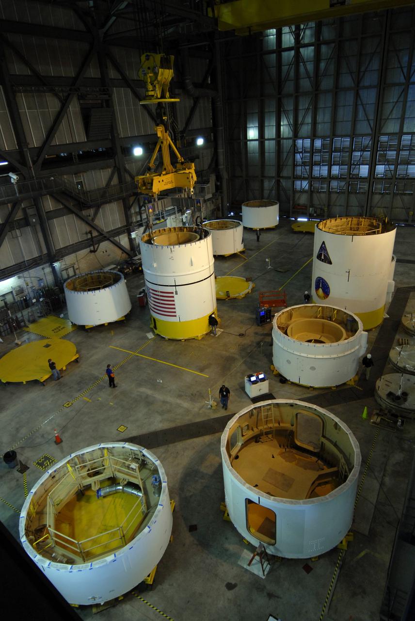
CAPE CANAVERAL, Fla. -- The upper stage simulator segments are positioned across the floor of the Vehicle Assembly Building's high bay 4 at NASA's Kennedy Space Center in Florida. Four of the segments are already stacked. The upper stage simulator will be used in the test flight identified as Ares I-X in 2009. Ares I-X is the test vehicle for the Ares I, which is part of the Constellation Program to return men to the moon and beyond. Ares I is the essential core of a safe, reliable, cost-effective space transportation system that eventually will carry crewed missions back to the moon, on to Mars and out into the solar system. Ares I may also use its 25-ton payload capacity to deliver resources and supplies to the International Space Station, or to "park" payloads in orbit for retrieval by other spacecraft bound for the moon or other destinations. The upper stage simulator comprises 11 segments, each approximately 18 feet in diameter. The simulator segments will simulate the mass and the outer mold line and will be more than 100 feet of the total vehicle height of 327 feet. Photo credit: NASA/Jack Pfaller
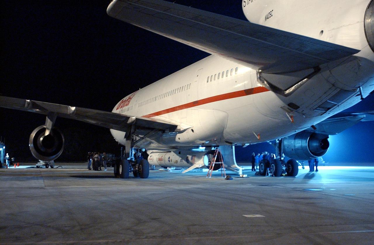
KENNEDY SPACE CENTER, FLA. -- Workers prepare to remove a Pegasus XL Expendable Launch Vehicle from the underside of an Orbital Sciences L-1011 aircraft. The aircraft, with the launch vehicle attached, arrived at the Cape Canaveral Air Force Station Skid Strip on Dec. 17. The Pegasus XL will undergo three flight simulations prior to its scheduled launch in late January 2003. It will carry NASA's Solar Radiation and Climate Experiment (SORCE) spacecraft into orbit. Built by Orbital Sciences Space Systems Group, SORCE will study and measure solar irradiance as a source of energy in the Earth's atmosphere with instruments built by the University of Colorado's Laboratory for Atmospheric and Space Physics (LASP).
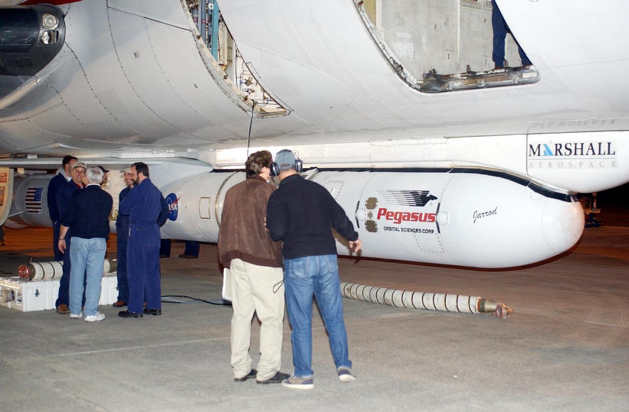
KENNEDY SPACE CENTER, FLA. -- Workers at the Cape Canaveral Air Force Station Skid Strip look over the Pegasus XL Expendable Launch Vehicle attached underneath the Orbital Sciences L-1011 aircraft. The Pegasus will be transported to the Multi-Payload Processing Facility for testing and verification. The Pegasus will undergo three flight simulations prior to its scheduled launch in late January 2003. The Pegasus XL will carry NASA's Solar Radiation and Climate Experiment (SORCE) into orbit. Built by Orbital Sciences Space Systems Group, SORCE will study and measure solar irradiance as a source of energy in the Earth's atmosphere. .
STS-97 Mission Specialist Carlos Noriega settles into his seat in Space Shuttle Endeavour on Launch Pad 39B. He and the rest of the crew are taking part in a simulated launch countdown, part of Terminal Countdown Demonstration Test activities that also include emergency egress training and familiarization with the payload. Mission STS-97 is the sixth construction flight to the International Space Station. Its payload includes the P6 Integrated Truss Structure and a photovoltaic (PV) module, with giant solar arrays that will provide power to the Station. The mission includes two spacewalks to complete the solar array connections. STS-97 is scheduled to launch Nov. 30 at about 10:05 p.m. EST

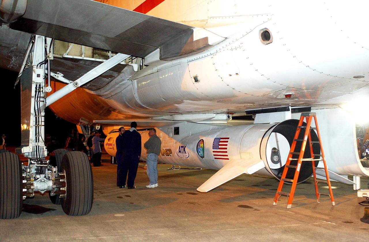
KENNEDY SPACE CENTER, FLA. -- Workers prepare a Pegasus XL Expendable Launch Vehicle for detachment from the underside of an Orbital Sciences L-1011 aircraft. The aircraft, with the launch vehicle nestled beneath, arrived at the Cape Canaveral Air Force Station Skid Strip on Dec. 17. The Pegasus XL will undergo three flight simulations prior to its scheduled launch in late January 2003. It will carry NASA's Solar Radiation and Climate Experiment (SORCE) spacecraft into orbit. Built by Orbital Sciences Space Systems Group, SORCE will study and measure solar irradiance as a source of energy in the Earth's atmosphere with instruments built by the University of Colorado's Laboratory for Atmospheric and Space Physics (LASP).
KENNEDY SPACE CENTER, FLA. -- Workers at the Cape Canaveral Air Force Station Skid Strip stand next to the Pegasus XL Expendable Launch Vehicle underneath the Orbital Sciences L-1011 aircraft. The Pegasus will be transported to the Multi-Payload Processing Facility for testing and verification. The Pegasus will undergo three flight simulations prior to its scheduled launch in late January 2003. The Pegasus XL will carry NASA's Solar Radiation and Climate Experiment (SORCE) into orbit. Built by Orbital Sciences Space Systems Group, SORCE will study and measure solar irradiance as a source of energy in the Earth's atmosphere. .
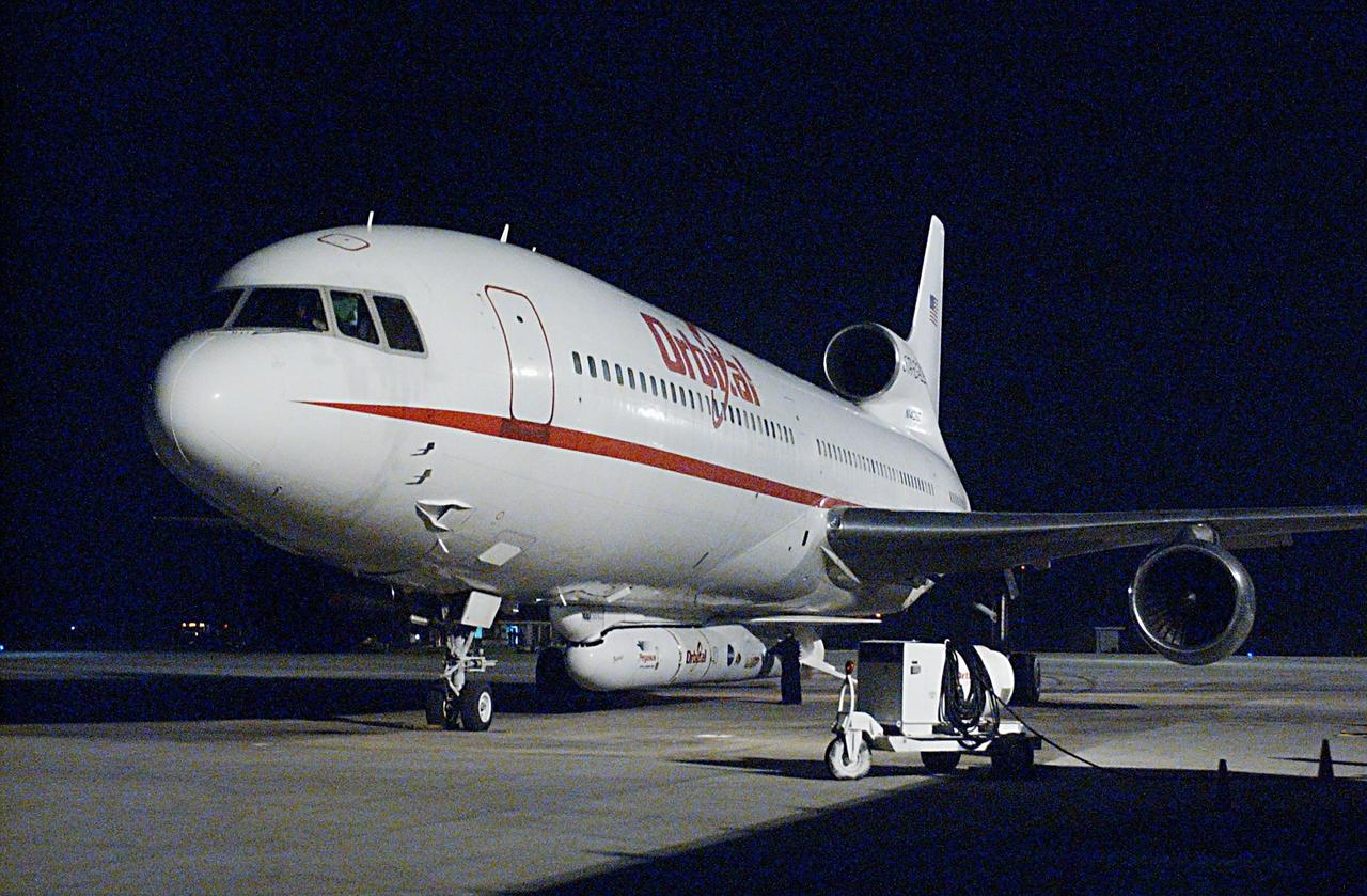
KENNEDY SPACE CENTER, FLA. - An Orbital Sciences L-1011 aircraft arrives at the Cape Canaveral Air Force Station Skid Strip. Attached underneath the aircraft is the Pegasus XL Expendable Launch Vehicle, which will be transported to the Multi-Payload Processing Facility for testing and verification. The Pegasus will undergo three flight simulations prior to its scheduled launch in late January 2003. The Pegasus XL will carry NASA's Solar Radiation and Climate Experiment (SORCE) into orbit. Built by Orbital Sciences Space Systems Group, SORCE will study and measure solar irradiance as a source of energy in the Earth's atmosphere. .
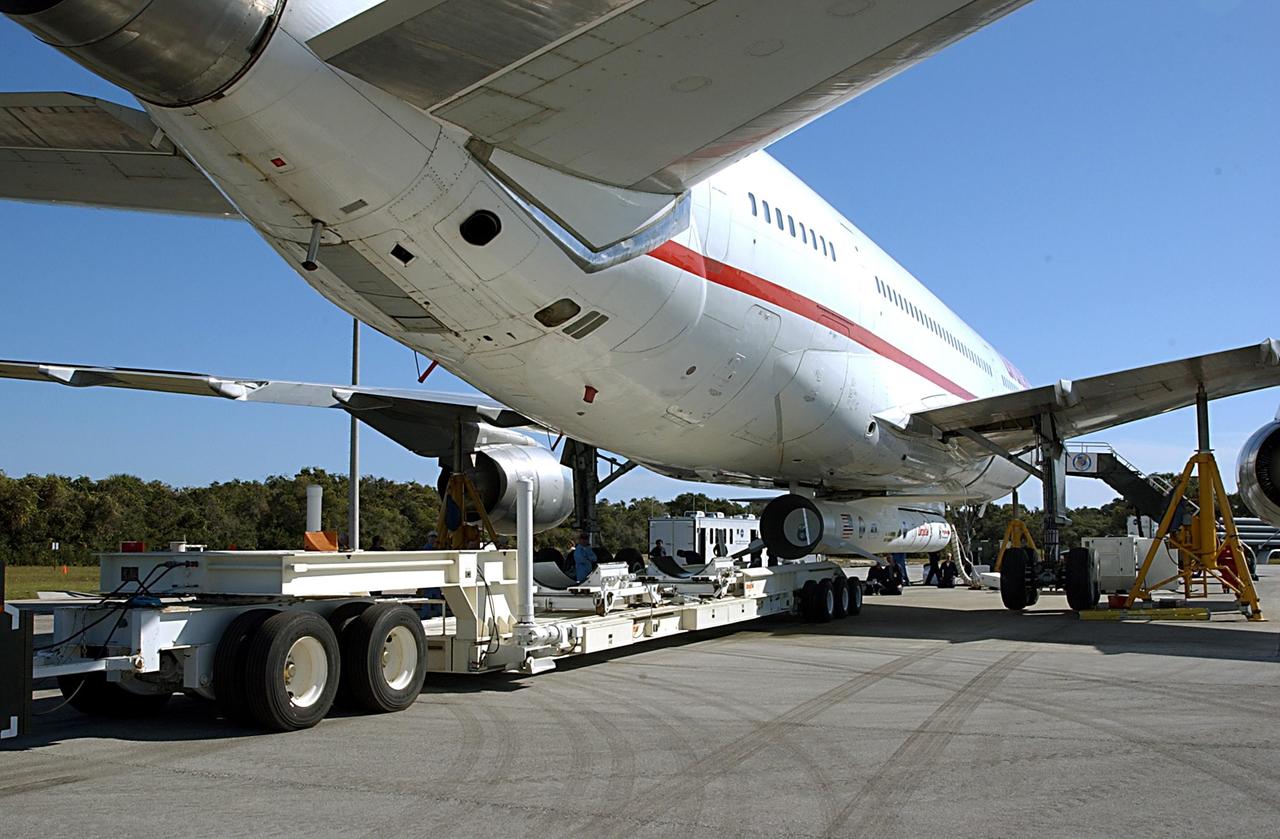
KENNEDY SPACE CENTER, FLA. -- A transporter is positioned below a Pegasus XL Expendable Launch Vehicle before its detachment from the underside of an Orbital Sciences L-1011 aircraft. The aircraft, with the launch vehicle nestled beneath, arrived at the Cape Canaveral Air Force Station Skid Strip on Dec. 17. The Pegasus XL will undergo three flight simulations prior to its scheduled launch in late January 2003. It will carry NASA's Solar Radiation and Climate Experiment (SORCE) spacecraft into orbit. Built by Orbital Sciences Space Systems Group, SORCE will study and measure solar irradiance as a source of energy in the Earth's atmosphere with instruments built by the University of Colorado's Laboratory for Atmospheric and Space Physics (LASP).
KENNEDY SPACE CENTER, FLA. -- A transporter is repositioned below a Pegasus XL Expendable Launch Vehicle before it is detached from the underside of an Orbital Sciences L-1011 aircraft. The aircraft, with the launch vehicle nestled beneath, arrived at the Cape Canaveral Air Force Station Skid Strip on Dec. 17. The Pegasus XL will undergo three flight simulations prior to its scheduled launch in late January 2003. It will carry NASA's Solar Radiation and Climate Experiment (SORCE) spacecraft into orbit. Built by Orbital Sciences Space Systems Group, SORCE will study and measure solar irradiance as a source of energy in the Earth's atmosphere with instruments built by the University of Colorado's Laboratory for Atmospheric and Space Physics (LASP).