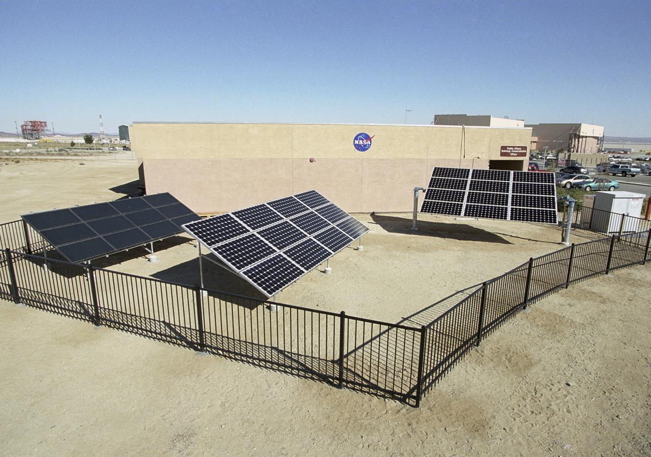
The 5 KW, state-of-the-art solar demonstration site at NASA Dryden is validating earthly use of solar cells developed for NASA's Helios solar-electric aircraft.
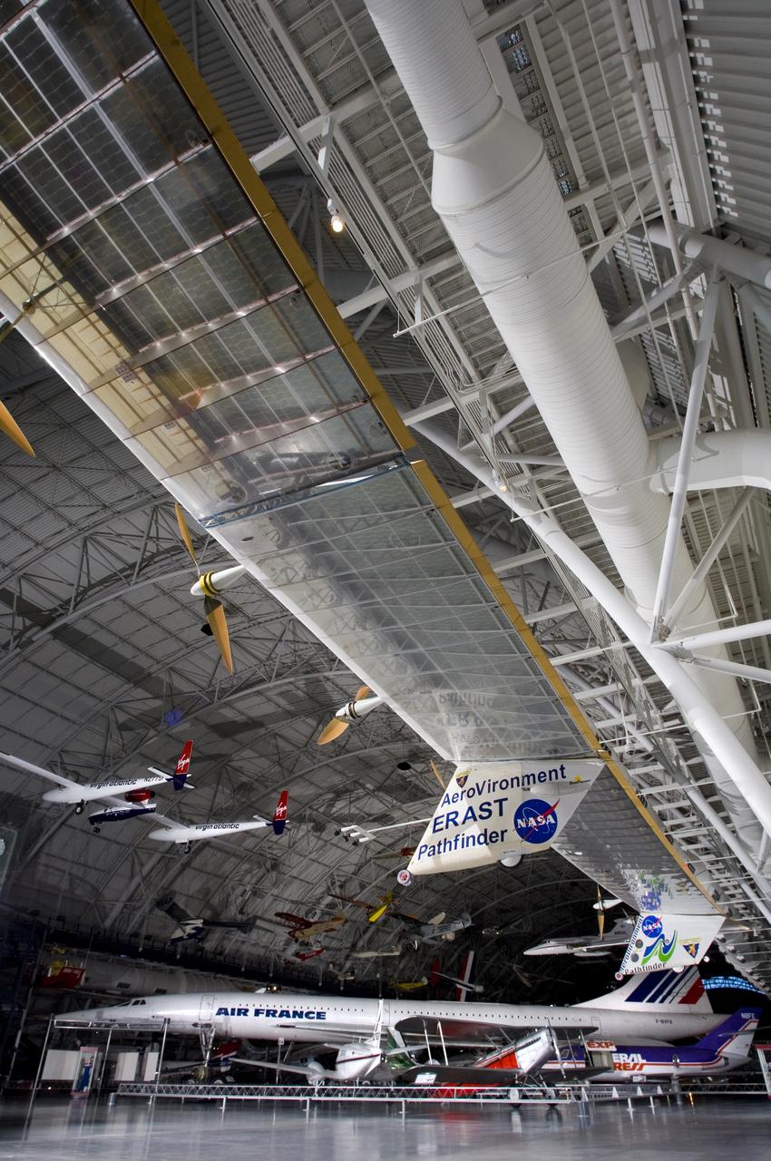
The record-setting AeroVironment/NASA Pathfinder-Plus solar-electric flying wing is enshrined in the National Air & Space Museum's Udvar-Hazy Center in Virginia.
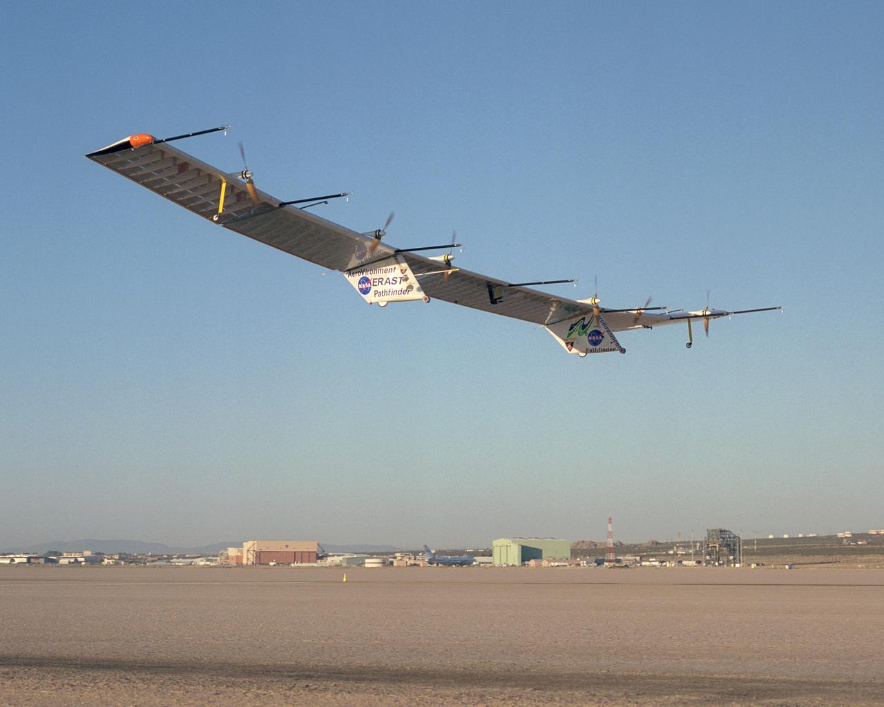
The Pathfinder-Plus solar-electric flying wing lifts off Rogers Dry Lake adjoining NASA Dryden Flight Research Center on a turbulence-measurement flight.
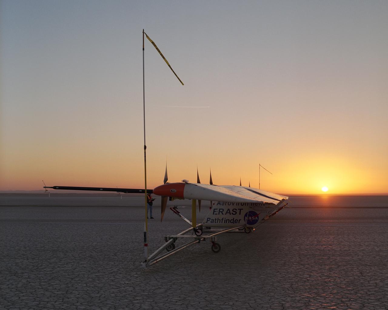
As the rising sun dawns over the parched bed of Rogers Dry Lake, AeroVironment's solar-electric Pathfinder-Plus awaits takeoff on its final research flight.
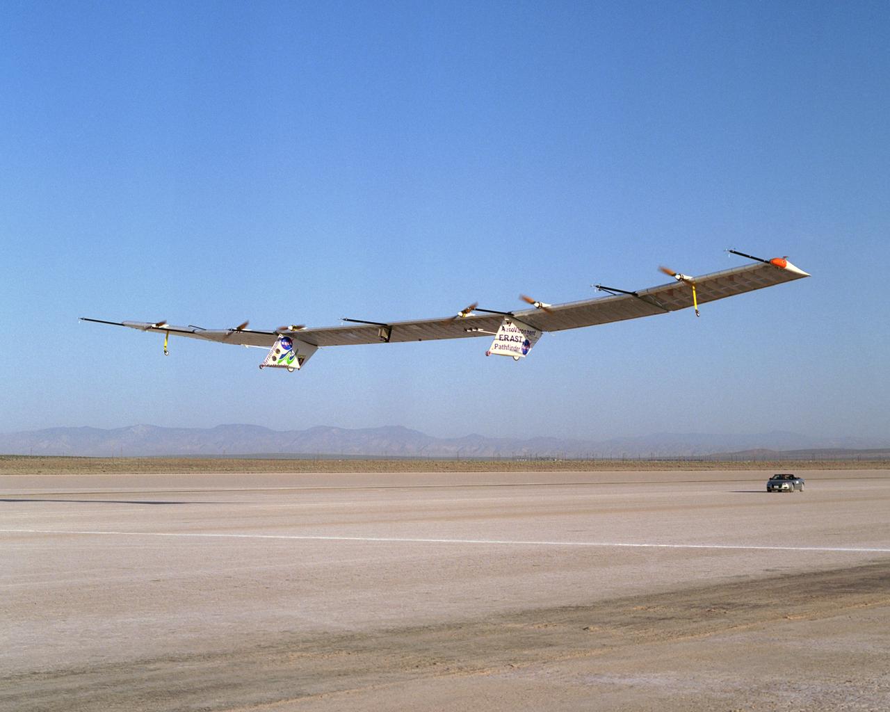
The Pathfinder-Plus solar-electric flying wing lifts off Rogers Dry Lake adjoining NASA Dryden Flight Research Center on a turbulence-measurement flight.
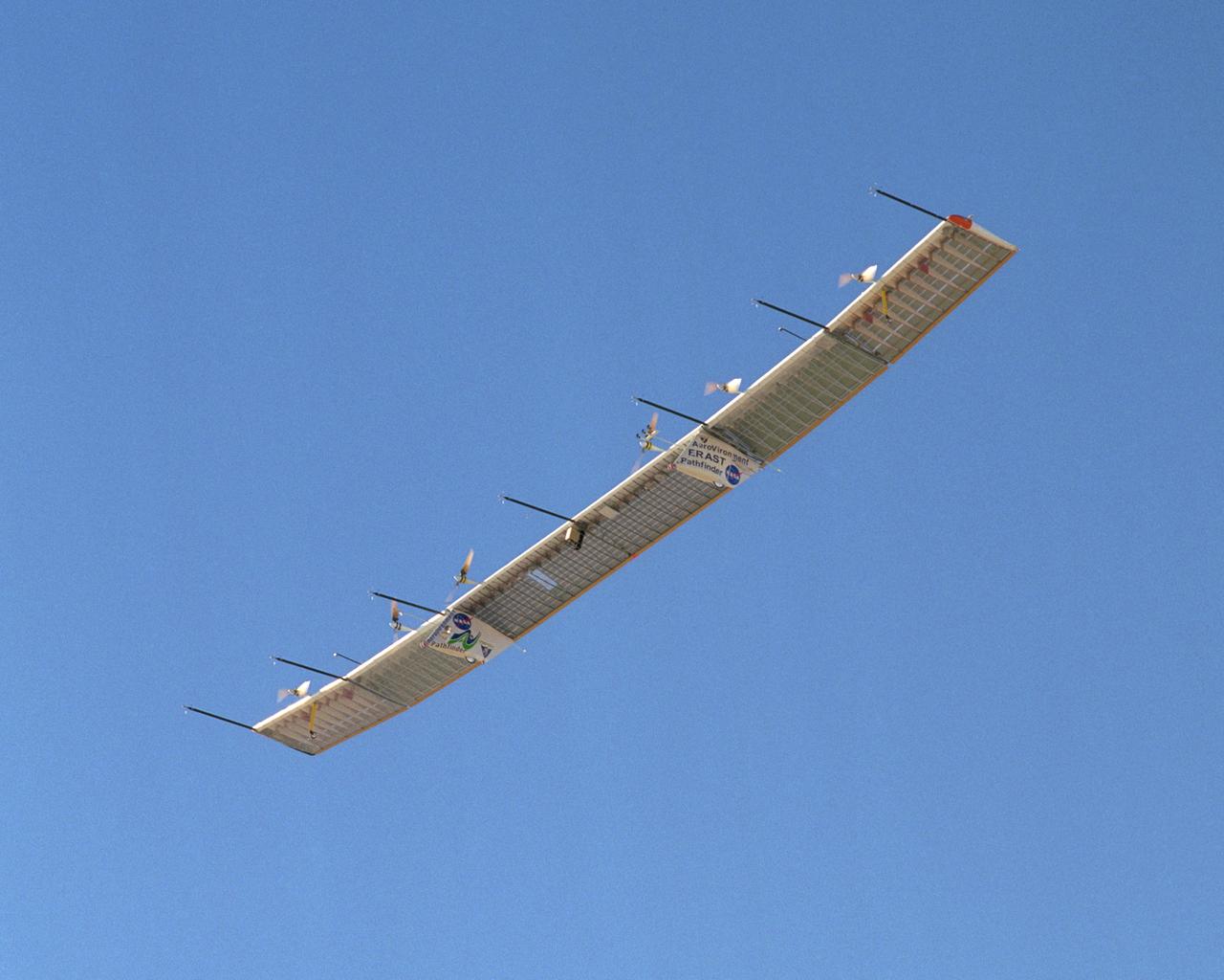
With its sensor booms projecting ahead of the wing, the Pathfinder-Plus solar-electric aircraft soars under a blue sky on a turbulence measurement research flight.
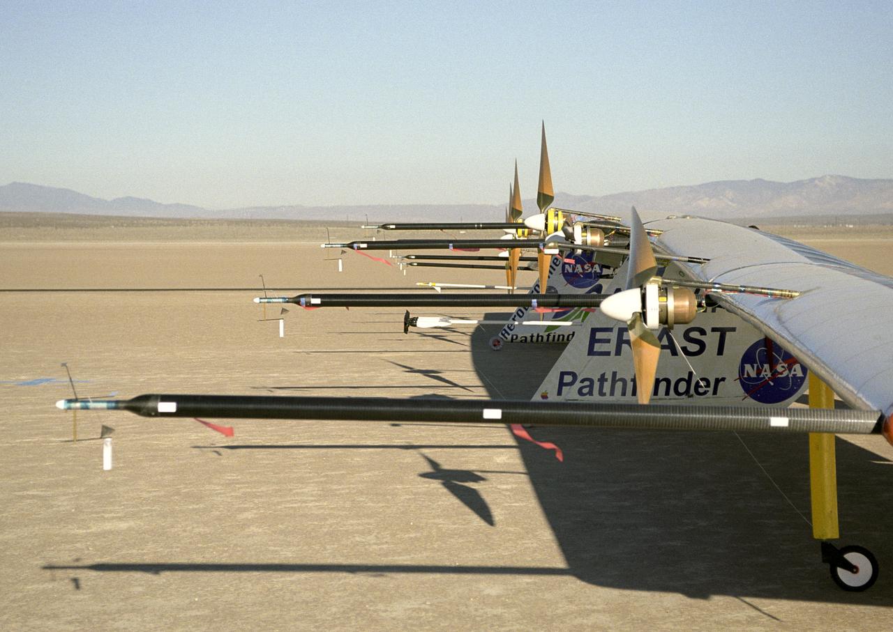
Sensitive instruments mounted on booms extending forward of the wing measure air turbulence and its effect on the stability of the Pathfinder-Plus solar-electric flying wing.
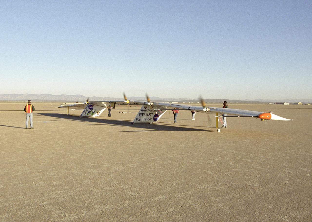
AeroVironment ground crew check out the operation of the Pathfinder-Plus solar aircraft's electric motors during combined systems tests on Rogers Dry Lake.
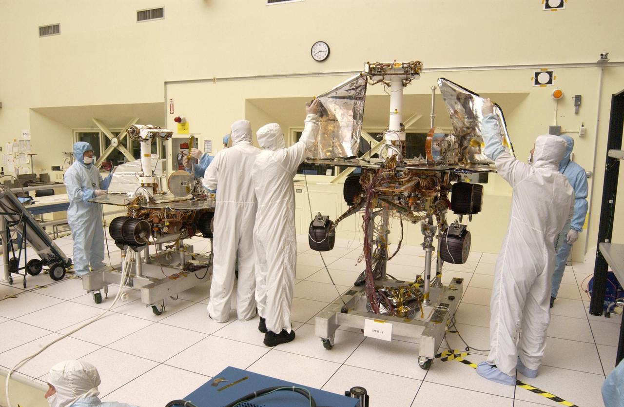
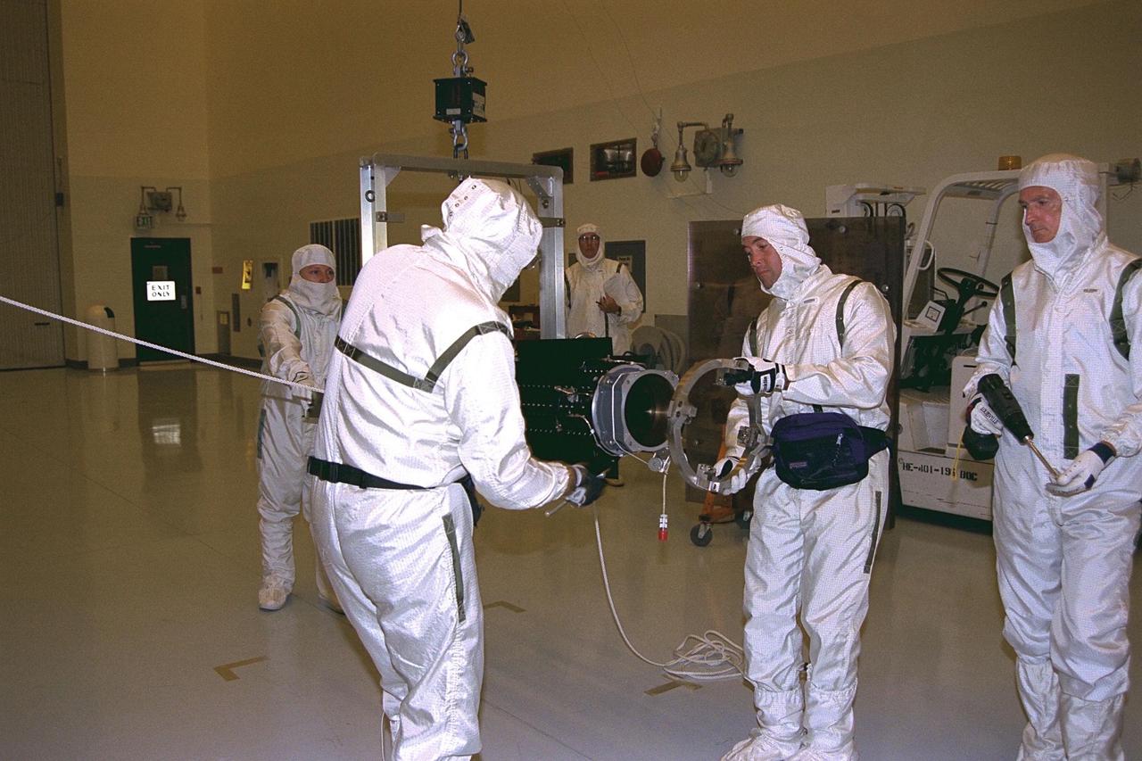
JPL engineers hand-deploying the solar arrays that provide the electrical power on NASA Mars Exploration Rover 1.
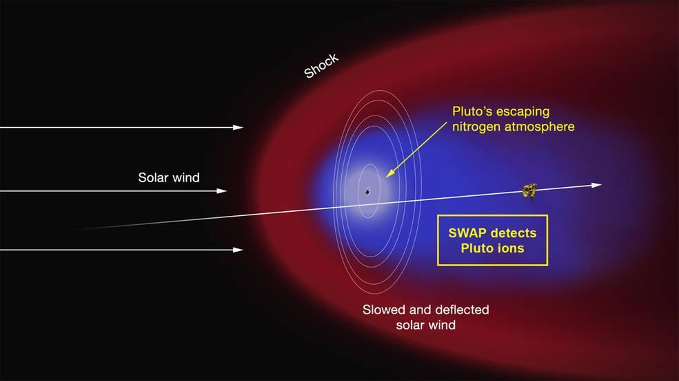
Artist concept of the interaction of the solar wind the supersonic outflow of electrically charged particles from the Sun with Pluto predominantly nitrogen atmosphere based on NASA New Horizons SWAP instrument.
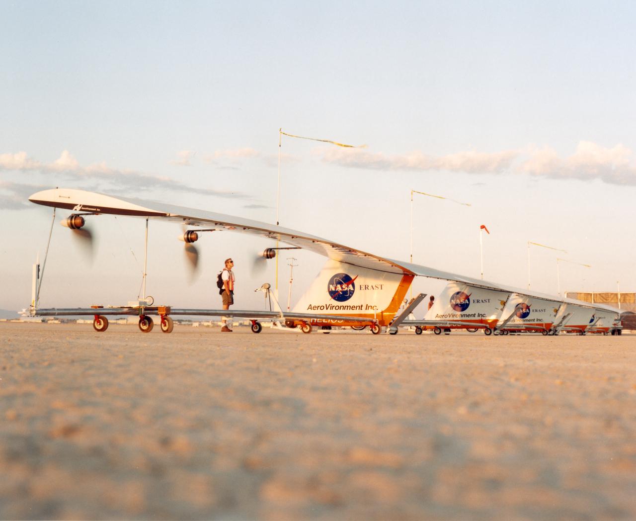
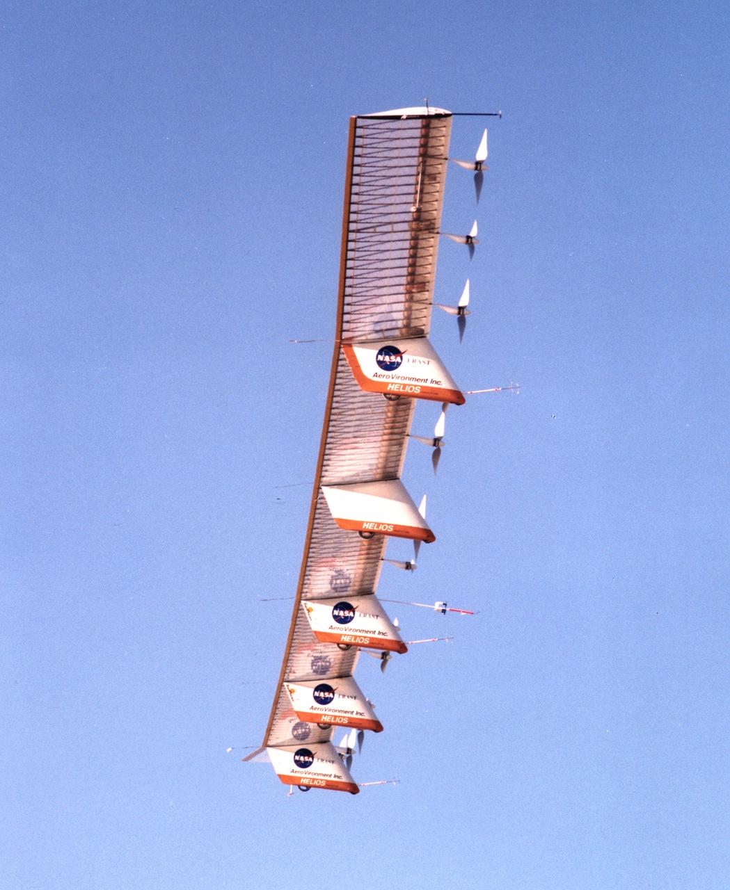
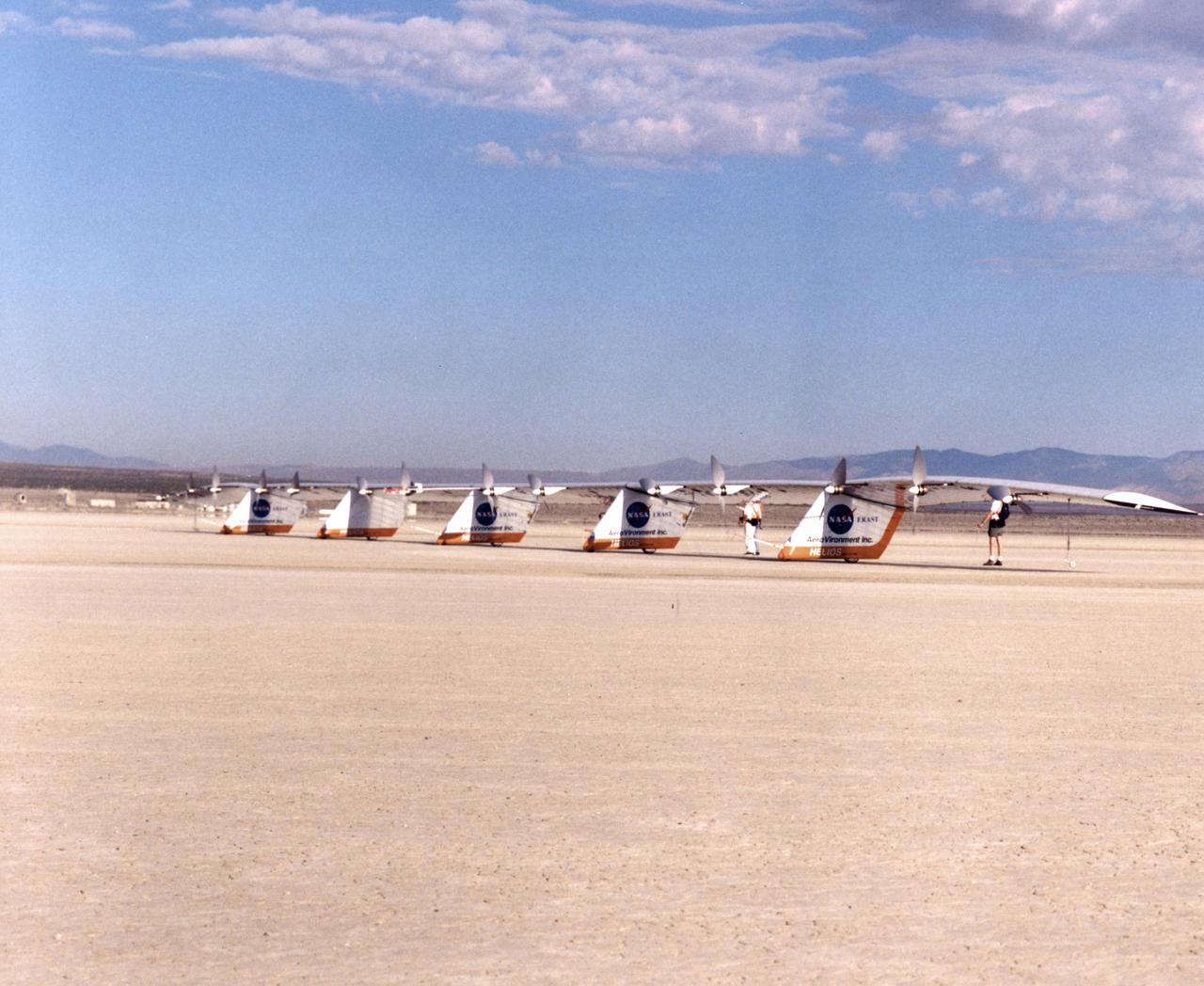
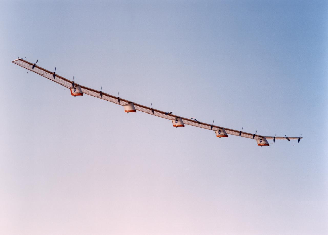
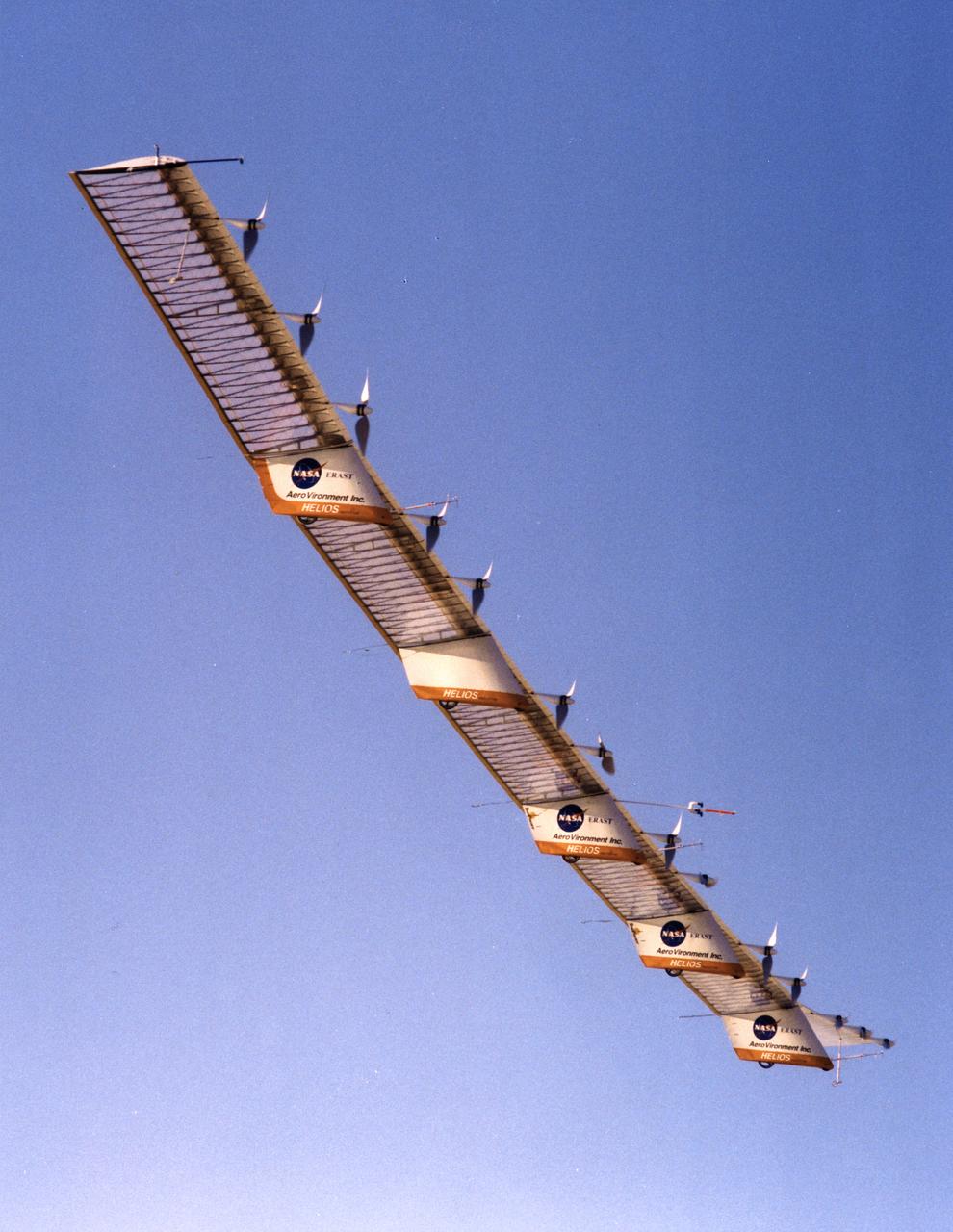
The Helios Prototype is an enlarged version of the Centurion flying wing, which flew a series of test flights at Dryden in late 1998. The craft has a wingspan of 247 feet, 41 feet greater than the Centurion, 2 1/2 times that of its solar-powered Pathfinder flying wing, and longer than either the Boeing 747 jetliner or Lockheed C-5 transport aircraft.
The Helios Prototype is an enlarged version of the Centurion flying wing, which flew a series of test flights at Dryden in late 1998. The craft has a wingspan of 247 feet, 41 feet greater than the Centurion, 2 1/2 times that of its solar-powered Pathfinder flying wing, and longer than either the Boeing 747 jetliner or Lockheed C-5 transport aircraft.
The Helios Prototype is an enlarged version of the Centurion flying wing, which flew a series of test flights at Dryden in late 1998. The craft has a wingspan of 247 feet, 41 feet greater than the Centurion, 2 1/2 times that of its solar-powered Pathfinder flying wing, and longer than either the Boeing 747 jetliner or Lockheed C-5 transport aircraft.
The Helios Prototype is an enlarged version of the Centurion flying wing, which flew a series of test flights at Dryden in late 1998. The craft has a wingspan of 247 feet, 41 feet greater than the Centurion, 2 1/2 times that of its solar-powered Pathfinder flying wing, and longer than either the Boeing 747 jetliner or Lockheed C-5 transport aircraft.
The Helios Prototype is an enlarged version of the Centurion flying wing, which flew a series of test flights at Dryden in late 1998. The craft has a wingspan of 247 feet, 41 feet greater than the Centurion, 2 1/2 times that of its solar-powered Pathfinder flying wing, and longer than either the Boeing 747 jetliner or Lockheed C-5 transport aircraft.
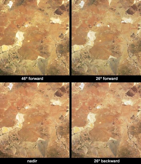
These images, from 8 April 2003 show that depending upon the position of the Sun, the solar power stations in California Mohave Desert can reflect solar energy from their large, mirror-like surfaces directly toward one of NASA Terra cameras.
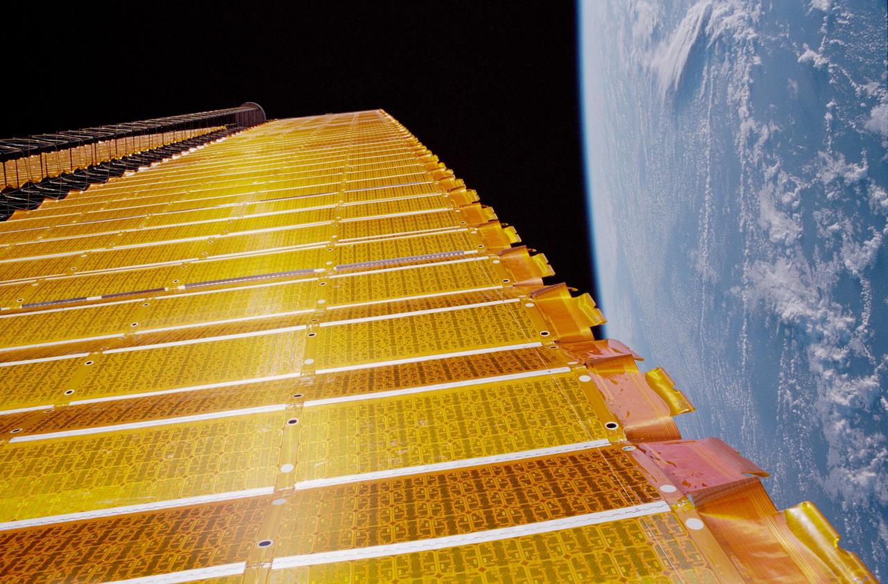
STS097-376-006 (7 Dec 2000) --- A close-up view of the P6 solar array on the International Space Station (ISS), backdropped against the blackness of space and the Earth?s horizon. The P6 solar array is the first of eight sets of solar arrays that at the completion of the space station construction in 2006, will comprise the station?s electrical power system, converting sunlight to electricity.
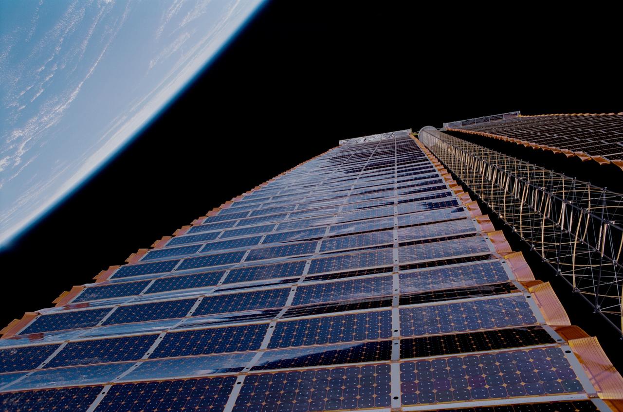
STS097-376-019 (7 December 2000) --- A close-up view of the P6 solar array on the International Space Station (ISS), backdropped against the blackness of space and the Earth’s horizon. The P6 solar array is the first of eight sets of solar arrays that at the completion of the space station construction in 2006, will comprise the station’s electrical power system, converting sunlight to electricity.
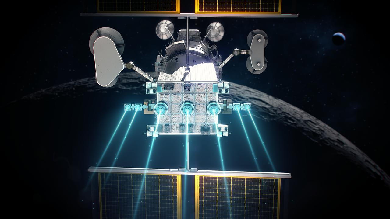
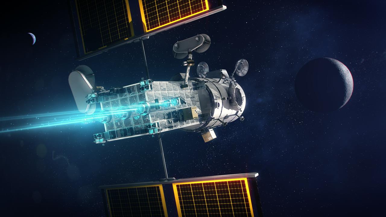
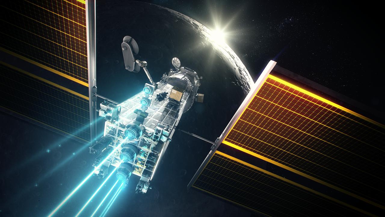
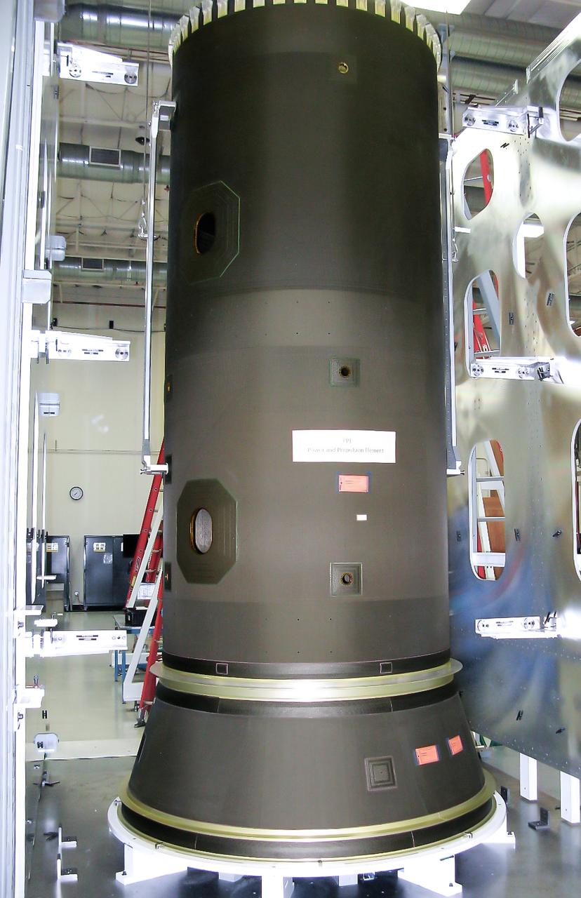
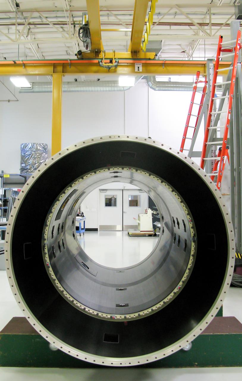
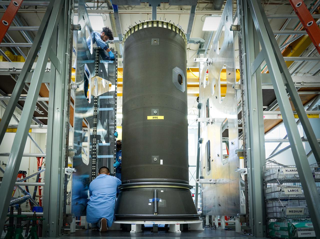
The Power and Propulsion Element's 12 kw thrusters will make Gateway the most powerful solar electric spacecraft ever flown.
The Power and Propulsion Element's 12 kw thrusters will make Gateway the most powerful solar electric spacecraft ever flown.
The Power and Propulsion Element's 12 kw thrusters will make Gateway the most powerful solar electric spacecraft ever flown.
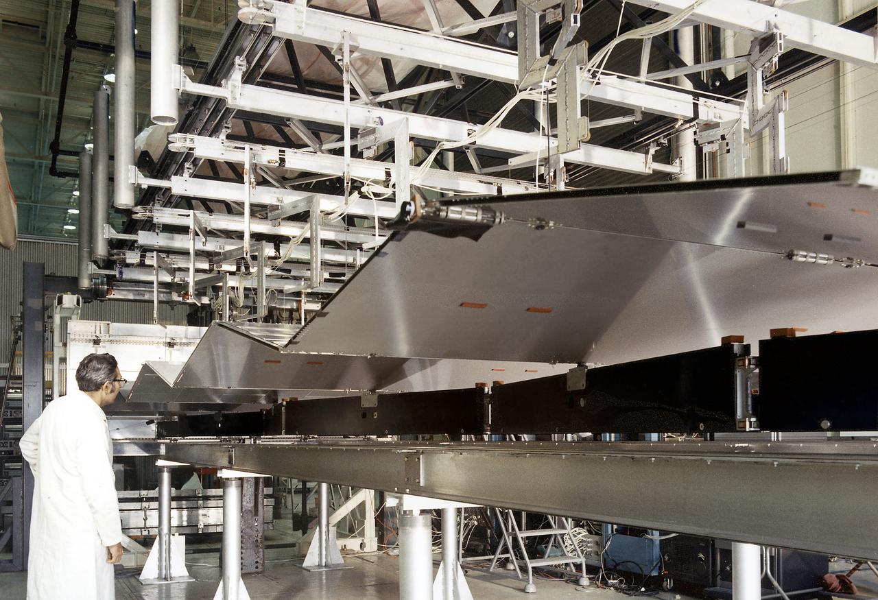
This is a photograph of a technician checking on a solar array wing for the Orbital Workshop as it is deployed. A solar array, consisting of two wings covered on one side with solar cells, was mounted outside the workshop to generate electrical power to augment the power generated by another solar array mounted on the solar observatory.
In the Space Station Processing Facility, Solar Array Wing-3, an element of the International Space Station, is lifted from a work stand to move it to the Integrated Electronic Assembly for testing. The solar array is scheduled to be launched on STS-97 in late November along with the P6 truss. The Station’s electrical power system (EPS) will use eight photovoltaic solar arrays to convert sunlight to electricity. Each of the eight solar arrays will be 112 feet long by 39 feet wide. The solar arrays are mounted on a “blanket” that can be folded like an accordion for delivery. Once in orbit, astronauts will deploy the blankets to their full size. Gimbals will be used to rotate the arrays so that they will face the Sun to provide maximum power to the Space Station
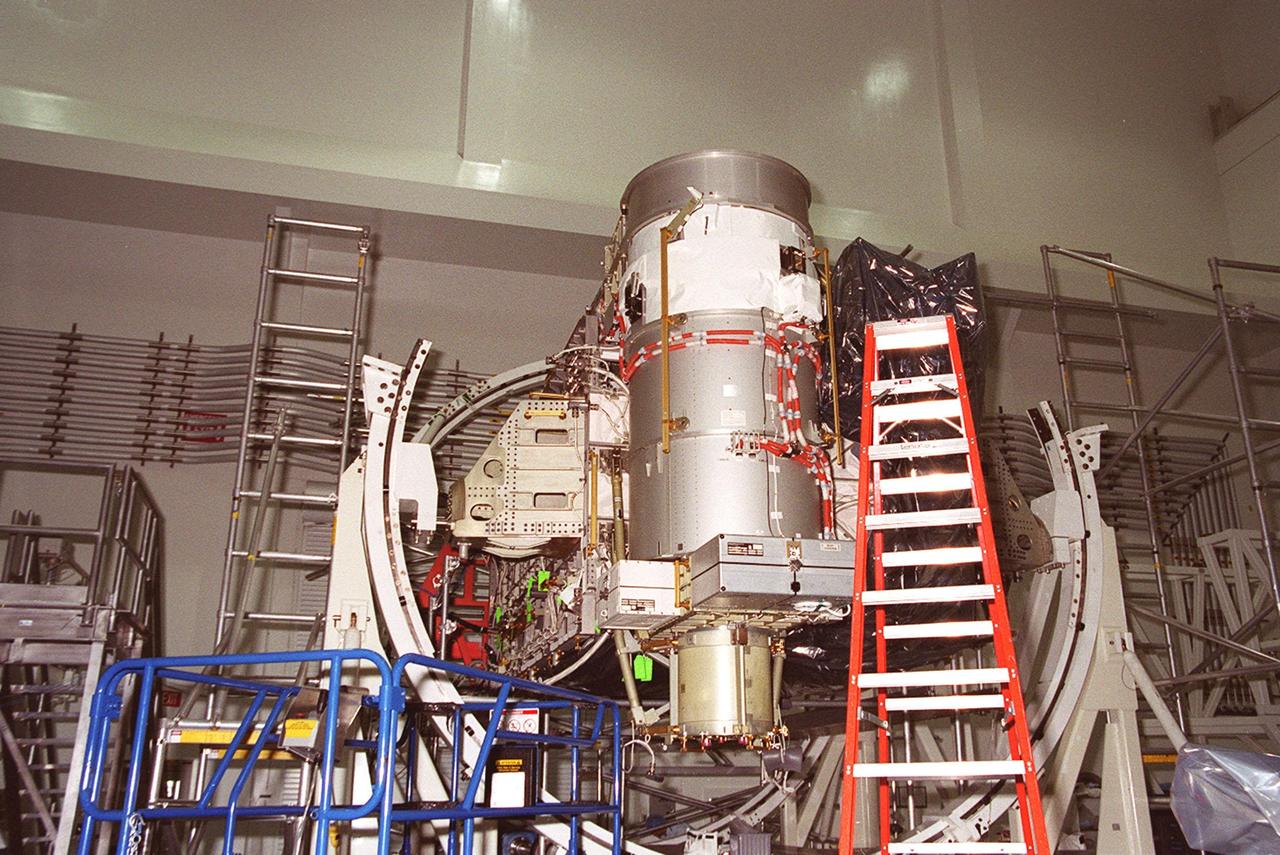
In the Space Station Processing Facility, Solar Array Wing-3, a component of the International Space Station, is installed in the Integrated Electronic Assembly where it will be tested. The solar array is scheduled to be launched on STS-97 in late November along with the P6 truss. The Station’s electrical power system (EPS) will use eight photovoltaic solar arrays to convert sunlight to electricity. Each of the eight solar arrays will be 112 feet long by 39 feet wide. The solar arrays are mounted on a “blanket” that can be folded like an accordion for delivery. Once in orbit, astronauts will deploy the blankets to their full size. Gimbals will be used to rotate the arrays so that they will face the Sun to provide maximum power to the Space Station
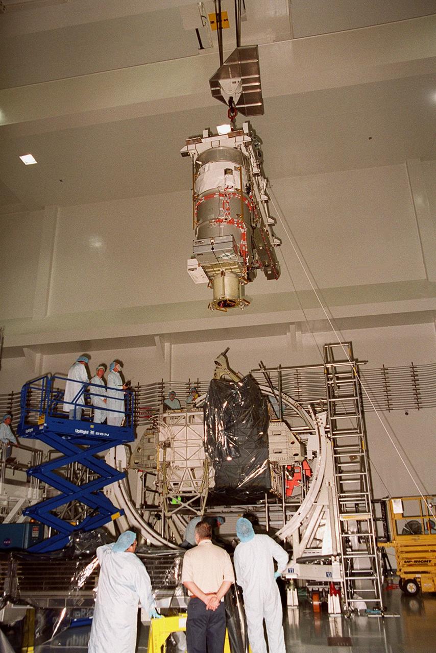
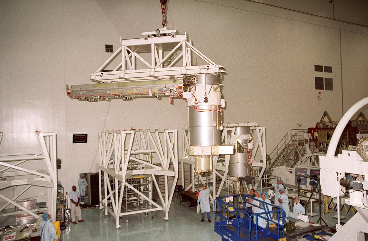
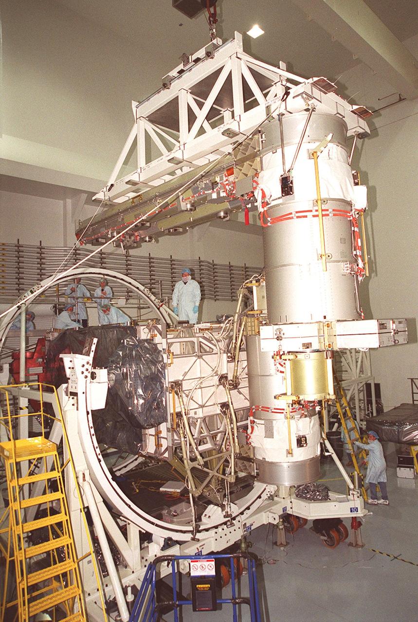
In the Space Station Processing Facility, Solar Array Wing-3 (at top), a component of the International Space Station, hovers above the Integrated Electronic Assembly where it will be installed for testing. The solar array is scheduled to be launched on STS-97 in late November along with the P6 truss. The Station’s electrical power system (EPS) will use eight photovoltaic solar arrays to convert sunlight to electricity. Each of the eight solar arrays will be 112 feet long by 39 feet wide. The solar arrays are mounted on a “blanket” that can be folded like an accordion for delivery. Once in orbit, astronauts will deploy the blankets to their full size. Gimbals will be used to rotate the arrays so that they will face the Sun to provide maximum power to the Space Station
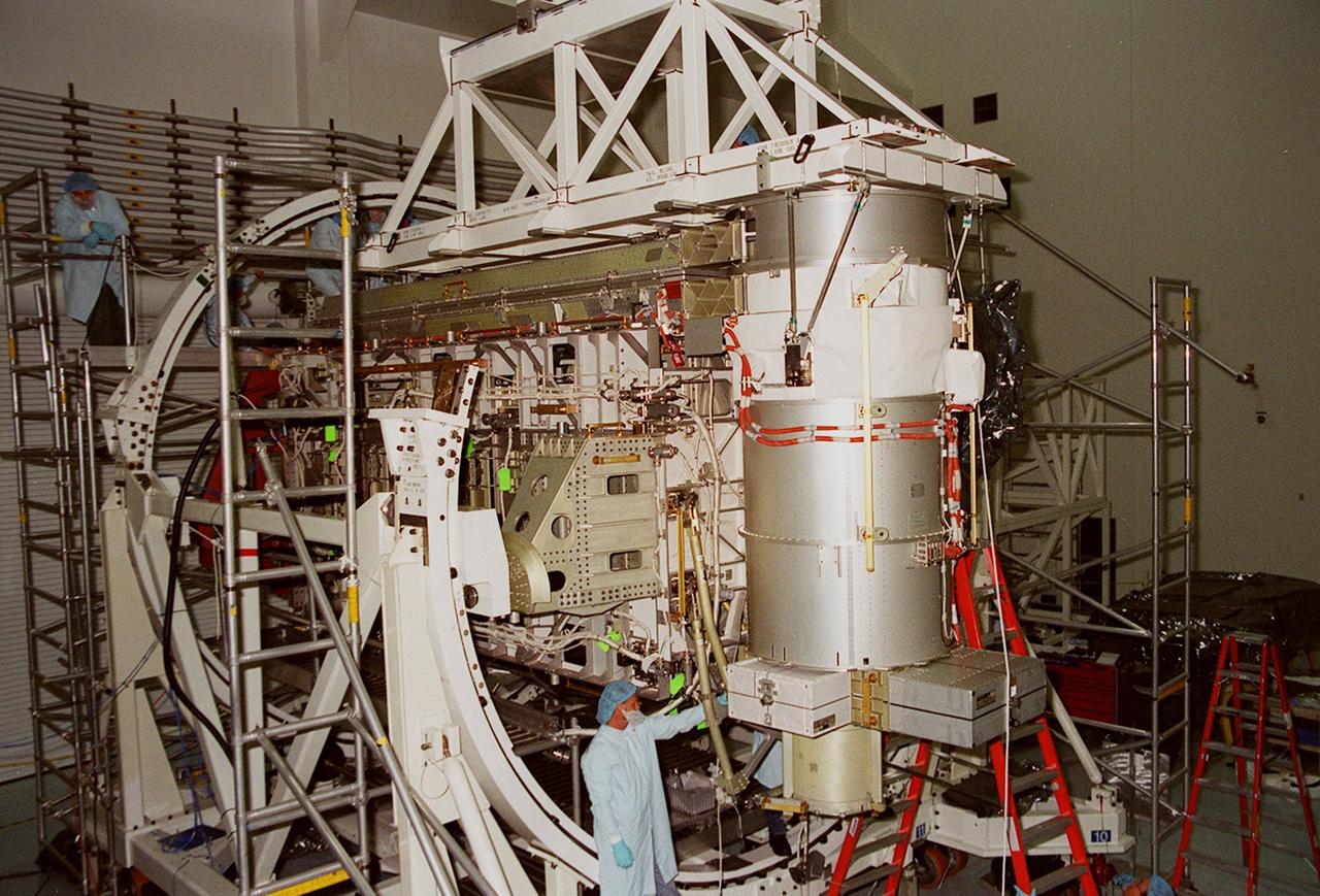
In the Space Station Processing Facility, Solar Array Wing-3, a component of the International Space Station, is installed in the Integrated Electronic Assembly where it will be tested. The solar array is scheduled to be launched on STS-97 in late November along with the P6 truss. The Station’s electrical power system (EPS) will use eight photovoltaic solar arrays to convert sunlight to electricity. Each of the eight solar arrays will be 112 feet long by 39 feet wide. The solar arrays are mounted on a “blanket” that can be folded like an accordion for delivery. Once in orbit, astronauts will deploy the blankets to their full size. Gimbals will be used to rotate the arrays so that they will face the Sun to provide maximum power to the Space Station
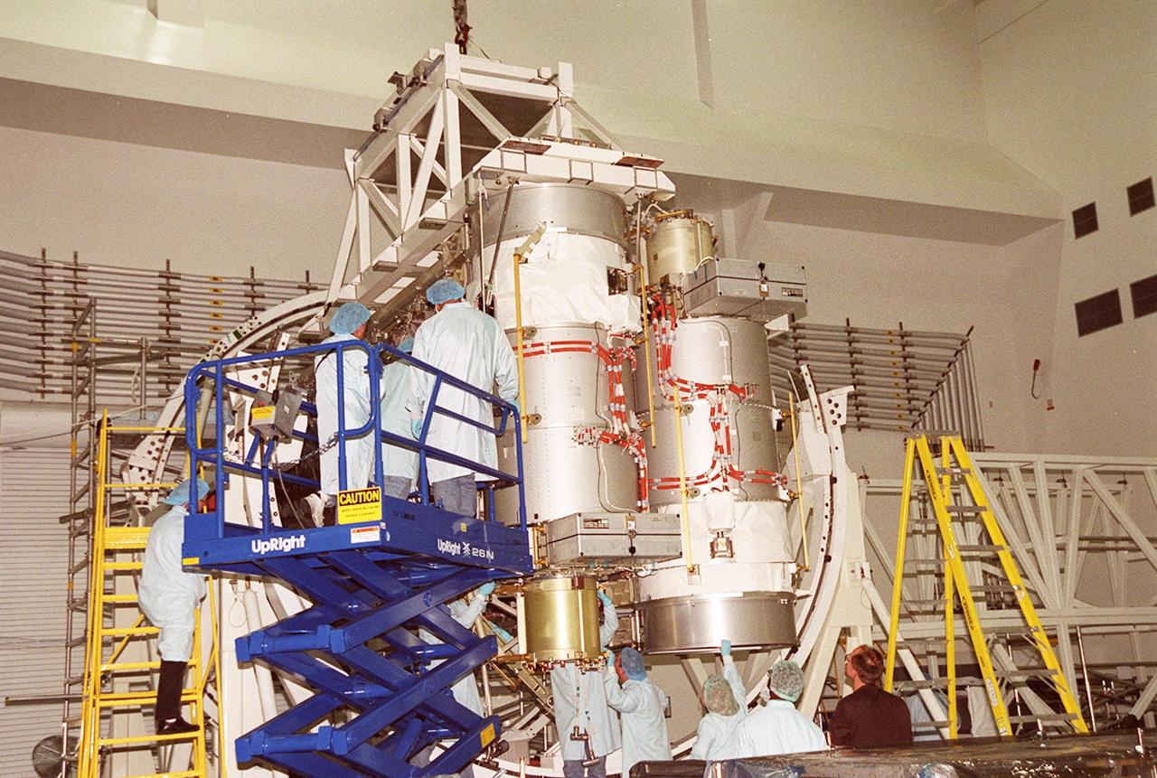
A solar array is nearly in place on the Integrated Equipment Assembly, next to Solar Array Wing-3, which is already installed. Components of the International Space Station, the arrays are scheduled to be launched on mission STS-97 in late November along with the P6 truss. The Station’s electrical power system (EPS) will use eight photovoltaic solar arrays to convert sunlight to electricity. Each of the eight solar arrays will be 112 feet long by 39 feet wide. The solar arrays are mounted on a “blanket” that can be folded like an accordion for delivery. Once in orbit, astronauts will deploy the blankets to their full size. Gimbals will be used to rotate the arrays so that they will face the Sun to provide maximum power to the Space Station
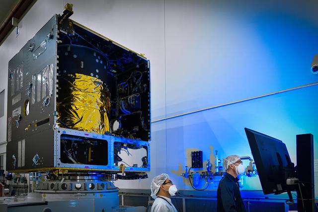
In this photo, taken in November 2020, technicians power on the main body of NASA's Psyche spacecraft — called the Solar Electric Propulsion (SEP) Chassis — for the first time, in a clean room at Maxar Technologies in Palo Alto, California. Maxar will deliver the SEP Chassis to NASA's Jet Propulsion Laboratory in Southern California in spring of 2021. Set to launch in August 2022, Psyche will investigate the composition of a metal-rich asteroid of the same name that lies in the main asteroid belt between Mars and Jupiter. The spacecraft will arrive in early 2026 and orbit the asteroid for nearly two years. https://photojournal.jpl.nasa.gov/catalog/PIA24326
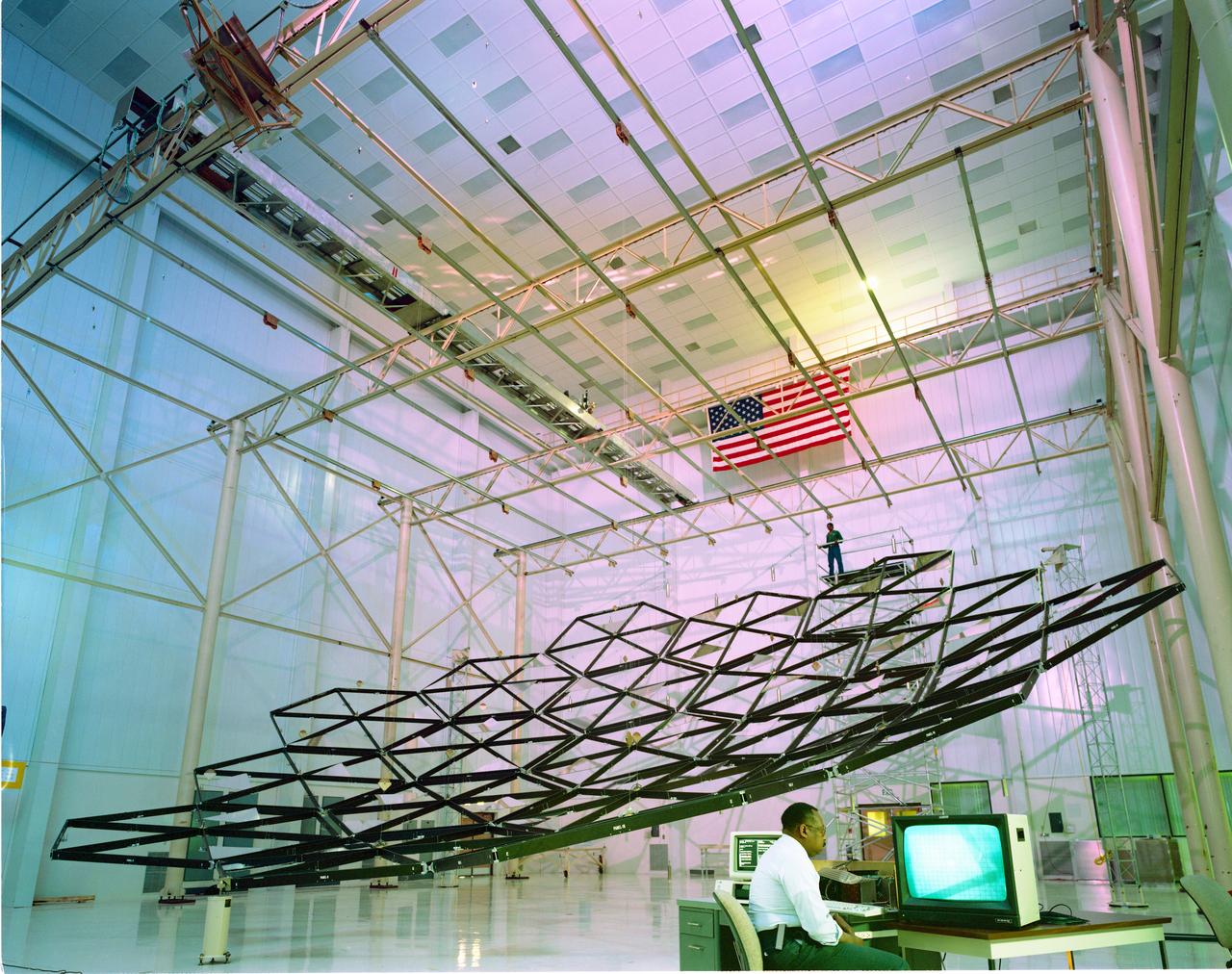
Testing of the Solar Dynamic Collector for Space Freedom. The solar dynamic power system includes a solar concentrator, which collects sunlight; a receiver, which accepts and stores the concentrated solar energy and transfers this energy to a gas; a Brayton turbine, alternator, and compressor unit, which generates electric power; and a radiator, which rejects waste heat.
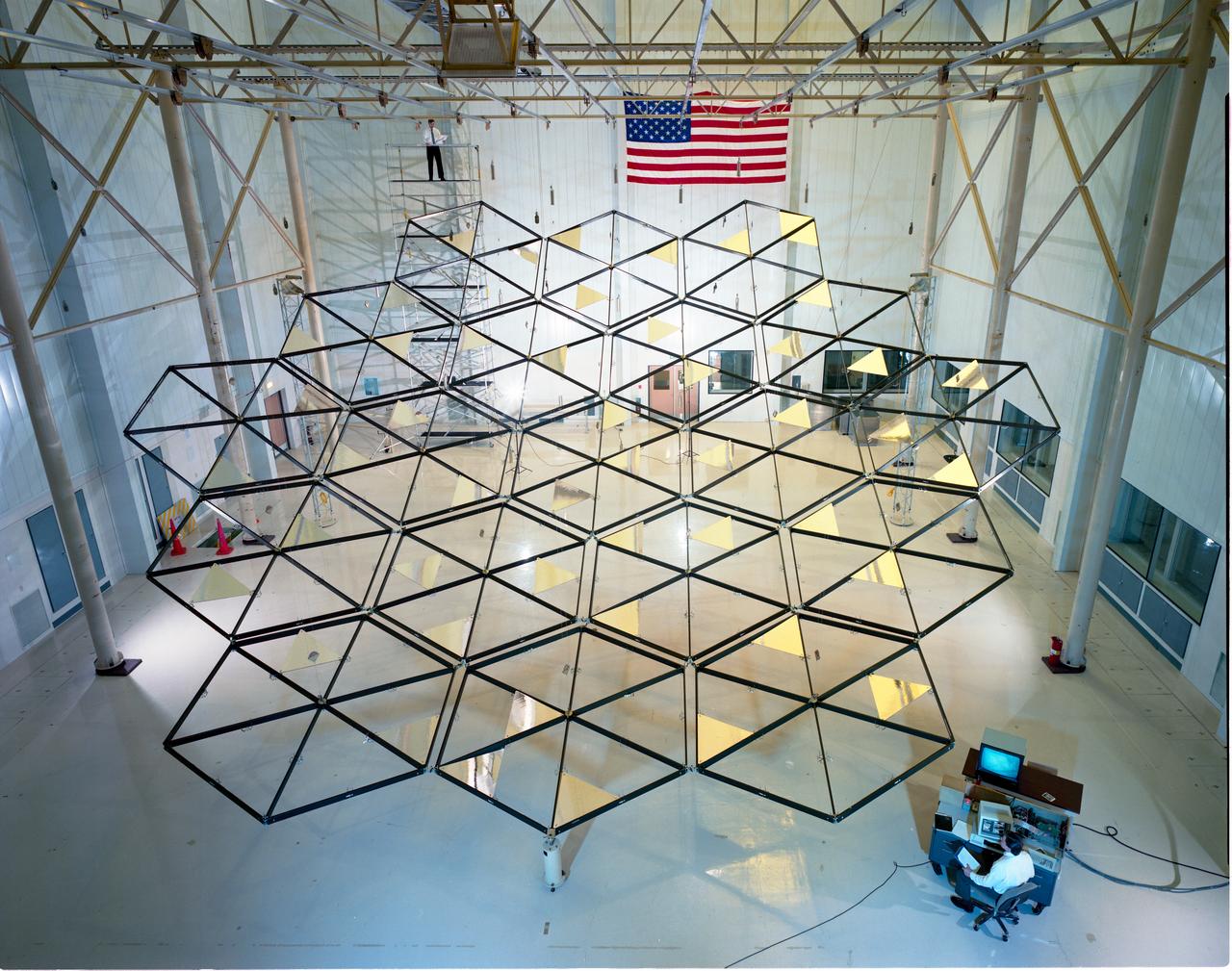
Testing of the Solar Dynamic Collector for Space Freedom. The solar dynamic power system includes a solar concentrator, which collects sunlight; a receiver, which accepts and stores the concentrated solar energy and transfers this energy to a gas; a Brayton turbine, alternator, and compressor unit, which generates electric power; and a radiator, which rejects waste heat.
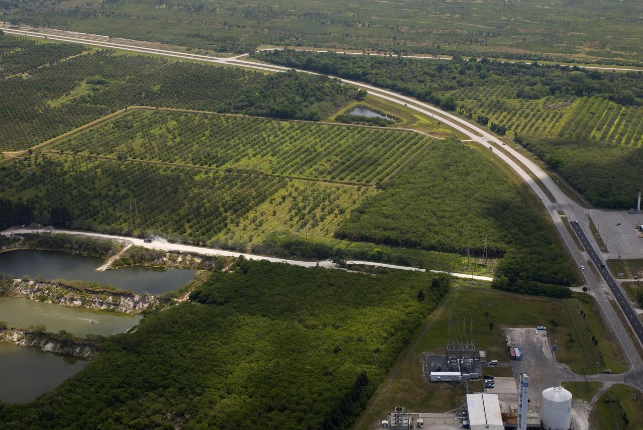
CAPE CANAVERAL, Fla. – This photo shows the area within NASA's Kennedy Space Center where a solar photovoltaic power generation system will be built as the result of an agreement between NASA and Florida Power & Light. The agreement is part of a new initiative that will cut reliance on fossil fuels and improve the environment by reducing greenhouse gas emissions. The major facility will produce an estimated 10 megawatts of electrical power, which can serve roughly 3,000 homes. A separate one-megawatt solar power facility will support the electrical needs of the center.
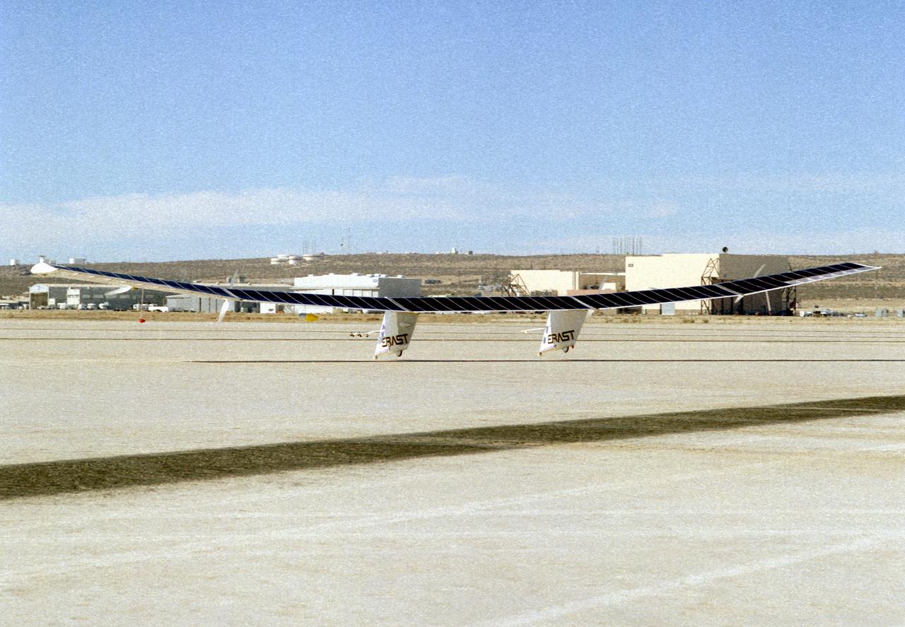
The Pathfinder research aircraft's solar cell arrays are prominently displayed as it touches down on the bed of Rogers Dry Lake at the Dryden Flight Research Center, Edwards, California, following a test flight. The solar arrays covered more than 75 percent of Pathfinder's upper wing surface, and provided electricity to power its six electric motors, flight controls, communications links and a host of scientific sensors.
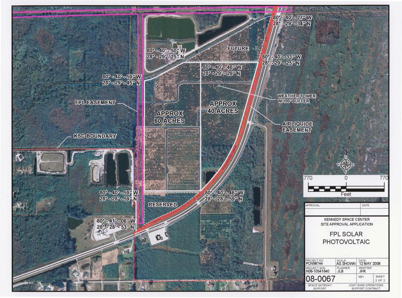
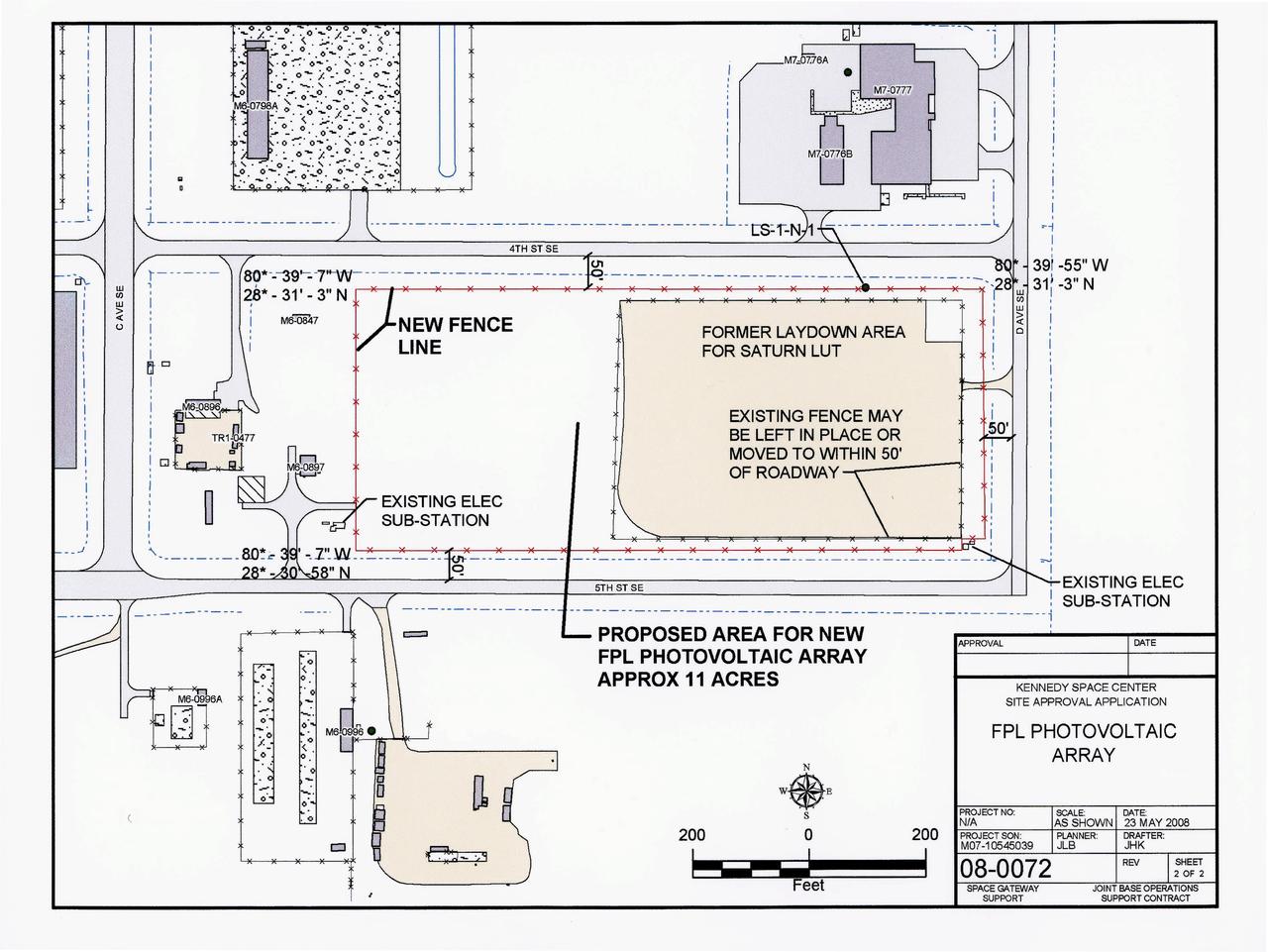
CAPE CANAVERAL, Fla. – This map shows the area within NASA's Kennedy Space Center where a solar photovoltaic power generation system will be built as the result of an agreement between NASA and Florida Power & Light. The agreement is part of a new initiative that will cut reliance on fossil fuels and improve the environment by reducing greenhouse gas emissions. The major facility will produce an estimated 10 megawatts of electrical power, which can serve roughly 3,000 homes. A separate one-megawatt solar power facility will support the electrical needs of the center.
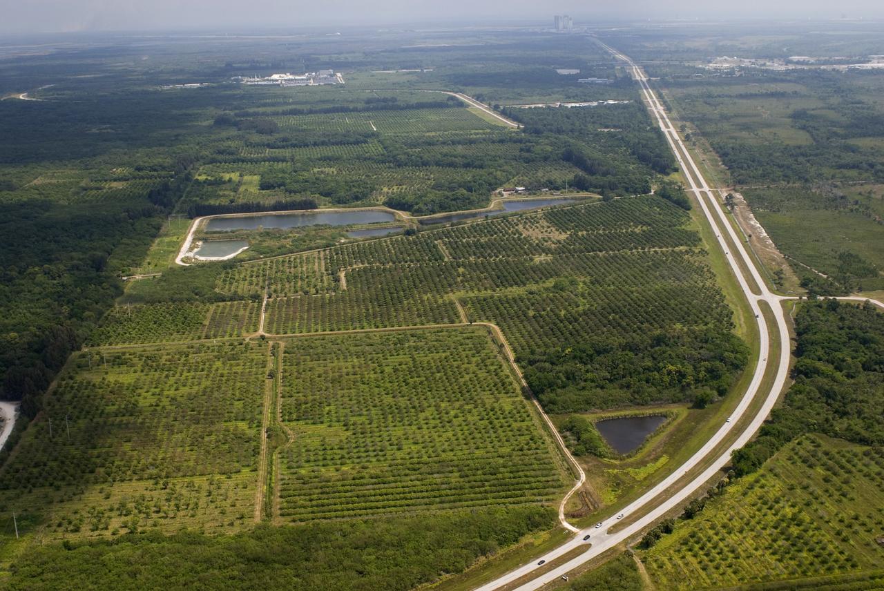
CAPE CANAVERAL, Fla. – This photo shows the area within NASA's Kennedy Space Center where a solar photovoltaic power generation system will be built as the result of an agreement between NASA and Florida Power & Light. The agreement is part of a new initiative that will cut reliance on fossil fuels and improve the environment by reducing greenhouse gas emissions. The major facility will produce an estimated 10 megawatts of electrical power, which can serve roughly 3,000 homes. A separate one-megawatt solar power facility will support the electrical needs of the center.
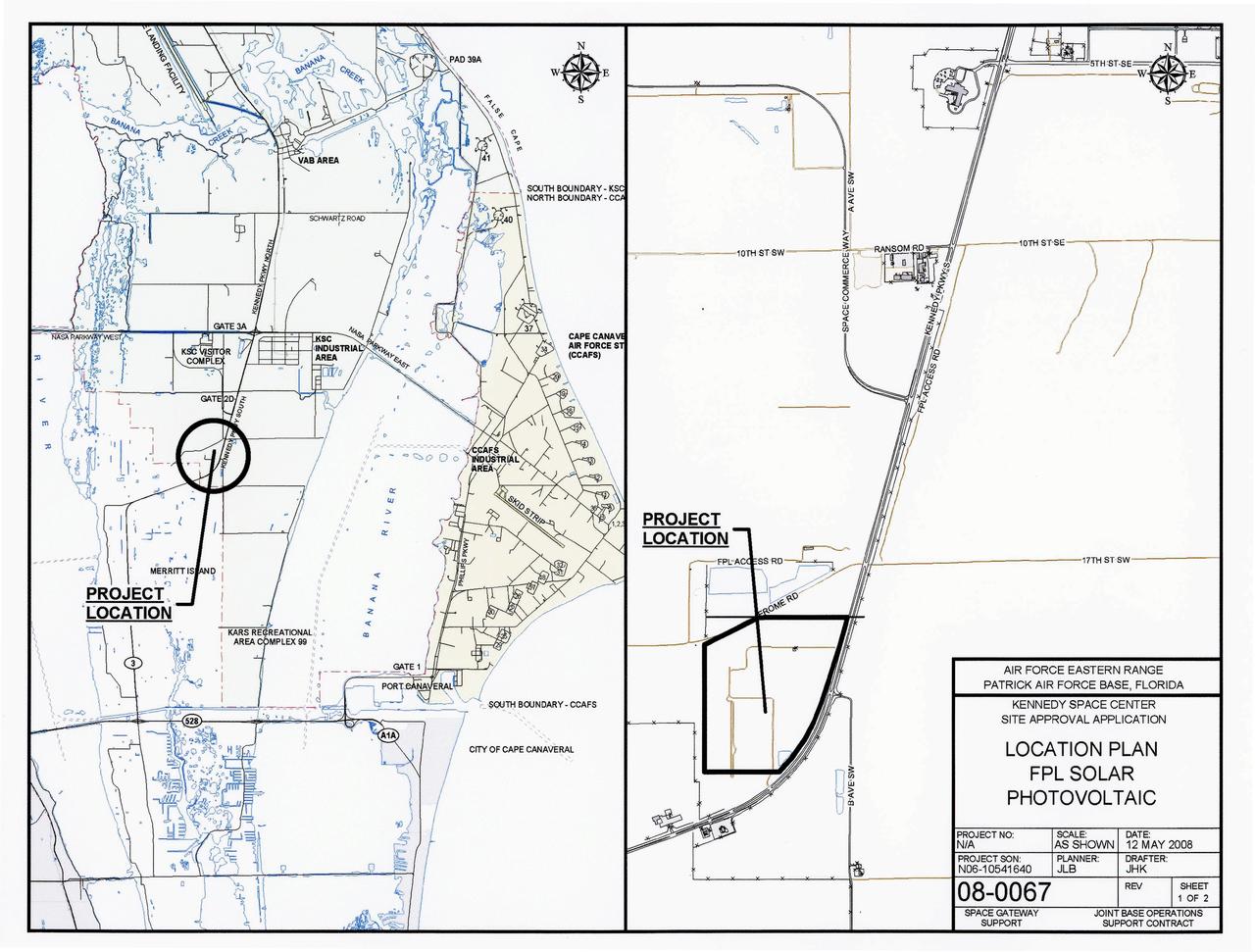
CAPE CANAVERAL, Fla. – This map shows the two sites within NASA's Kennedy Space Center where a solar photovoltaic power generation system will be built as the result of an agreement between NASA and Florida Power & Light. The agreement is part of a new initiative that will cut reliance on fossil fuels and improve the environment by reducing greenhouse gas emissions. The major facility will produce an estimated 10 megawatts of electrical power, which can serve roughly 3,000 homes. A separate one-megawatt solar power facility will support the electrical needs of the center.
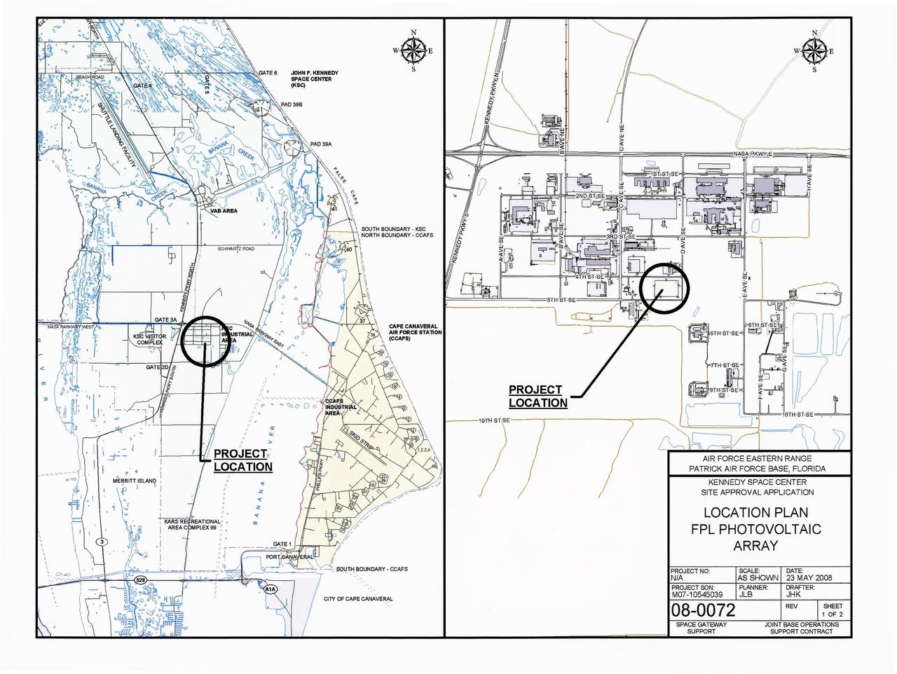
CAPE CANAVERAL, Fla. – This map shows the two sites within NASA's Kennedy Space Center where a solar photovoltaic power generation system will be built as the result of an agreement between NASA and Florida Power & Light. The agreement is part of a new initiative that will cut reliance on fossil fuels and improve the environment by reducing greenhouse gas emissions. The major facility will produce an estimated 10 megawatts of electrical power, which can serve roughly 3,000 homes. A separate one-megawatt solar power facility will support the electrical needs of the center.

This is the crew insignia for STS-97 which delivered, assembled, and activated the U.S. electrical power system onboard the International Space Station (ISS). The electrical power system, which is built into a 47-foot integrated truss structure known as P6, consists of solar arrays, radiators, batteries, and electronics. P6 was prepared for subsequent deployments of larger solar arrays and radiator, a critical step in the activation of the electrical power system that will eventually provide the power necessary for the first ISS crews to live and work in the U.S. segment. The crew patch depicts the space shuttle docked to the ISS in low Earth orbit after the activation of the P6 electrical power system. Gold and silver were used to highlight the portion of the ISS that were installed by the STS-97 crew. The sun, central to the design, is the source of energy for the ISS. The crew member names surround the outer border of the patch.
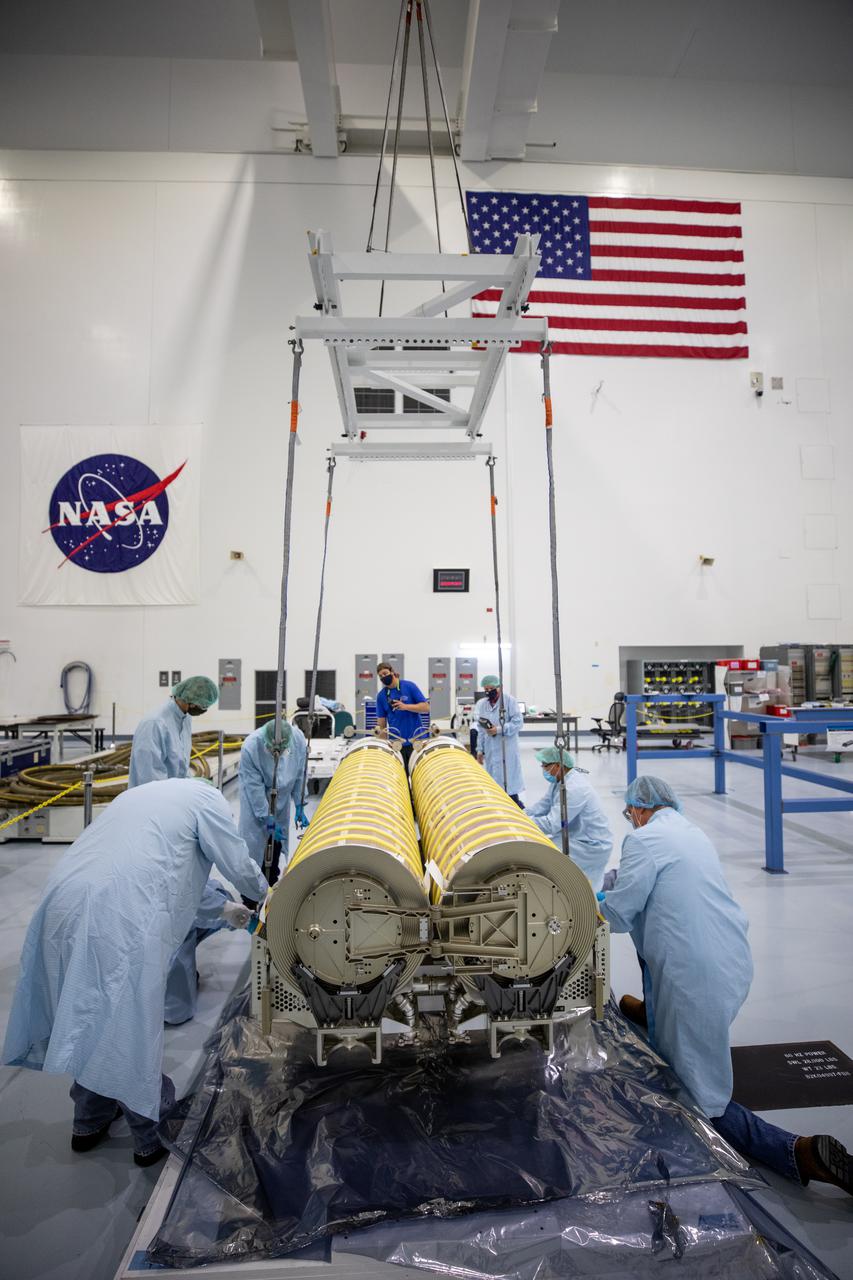
NASA and Boeing workers move solar arrays for the International Space Station to flight support equipment in the high bay of the Space Station Processing Facility at NASA’s Kennedy Space Center in Florida on April 2, 2021. The 63- by- 20-foot solar arrays will launch to the International Space Station later this year. They are the first two of six new solar arrays that in total will produce more than 120 kilowatts of electricity from the Sun’s energy, enough to power more than 40 average U.S. homes. Combined with the eight original, larger arrays, this advanced hardware will provide 215 kilowatts of energy, a 20 to 30 percent increase in power, helping maximize the space station’s capabilities for years to come. The arrays will produce electricity to sustain the station’s systems and equipment, plus augment the electricity available to continue a wide variety of public and private experiments and research in the microgravity environment of low-Earth orbit.
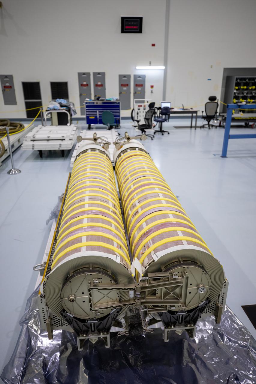
In view are the first two of six solar arrays shortly before NASA and Boeing workers began lifting them into flight support equipment the Space Station Processing Facility at NASA’s Kennedy Space Center in Florida on April 2, 2021. The 63- by- 20-foot solar arrays will launch to the International Space Station later this year. The six new solar arrays in total will produce more than 120 kilowatts of electricity from the Sun’s energy, enough to power more than 40 average U.S. homes. Combined with the eight original, larger arrays, this advanced hardware will provide 215 kilowatts of energy, a 20 to 30 percent increase in power, helping maximize the space station’s capabilities for years to come. The arrays will produce electricity to sustain the station’s systems and equipment, plus augment the electricity available to continue a wide variety of public and private experiments and research in the microgravity environment of low-Earth orbit.
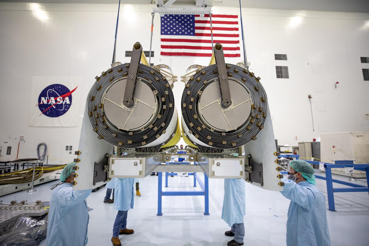
NASA and Boeing workers help position the solar arrays onto flight support equipment inside the high bay of the Space Station Processing Facility at NASA’s Kennedy Space Center in Florida on April 2, 2021. The 63- by- 20-foot solar arrays will launch to the International Space Station later this year. They are the first two of six new solar arrays that in total will produce more than 120 kilowatts of electricity from the Sun’s energy, enough to power more than 40 average U.S. homes. Combined with the eight original, larger arrays, this advanced hardware will provide 215 kilowatts of energy, a 20 to 30 percent increase in power, helping maximize the space station’s capabilities for years to come. The arrays will produce electricity to sustain the station’s systems and equipment, plus augment the electricity available to continue a wide variety of public and private experiments and research in the microgravity environment of low-Earth orbit.
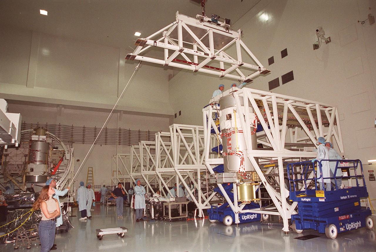
An overhead crane in the Space Station Processing Facility lifts a solar array as workers stand by to help guide it. The solar array will be installed onto the Integrated Equipment Assembly (IEA). A component of the International Space Station, the solar array is the second one being installed on the IEA. The arrays are scheduled to be launched on mission STS-97 in late November along with the P6 truss. The Station’s electrical power system (EPS) will use eight photovoltaic solar arrays to convert sunlight to electricity. Each of the eight solar arrays will be 112 feet long by 39 feet wide. The solar arrays are mounted on a “blanket” that can be folded like an accordion for delivery. Once in orbit, astronauts will deploy the blankets to their full size. Gimbals will be used to rotate the arrays so that they will face the Sun to provide maximum power to the Space Station
Workers rise to the occasion on accordion lifts as they oversee the movement of solar array in front of them. The solar array will be installed onto the Integrated Equipment Assembly (IEA). A component of the International Space Station, the solar array is the second one being installed on the IEA. The arrays are scheduled to be launched on mission STS-97 in late November along with the P6 truss. The Station’s electrical power system (EPS) will use eight photovoltaic solar arrays to convert sunlight to electricity. Each of the eight solar arrays will be 112 feet long by 39 feet wide. The solar arrays are mounted on a “blanket” that can be folded like an accordion for delivery. Once in orbit, astronauts will deploy the blankets to their full size. Gimbals will be used to rotate the arrays so that they will face the Sun to provide maximum power to the Space Station
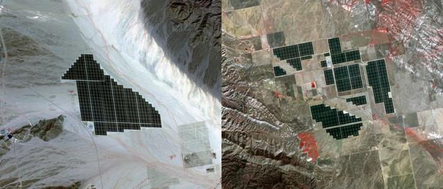
On February 15, 2015 the Desert Sunlight solar project in California’s Mojave Desert became operational. This image from NASA Terra spacecraft shows the 550-megawatt plant generates enough electricity to power 160,000 average homes. Covering an area of 16 km2, the 8.8 million cadmium telluride photovoltaic modules take advantage of the more than 300 days of sunshine. Desert Sunlight joins the similar-sized Topaz Solar Farm in San Luis Obispo County, CA, that became operational in June, 2014. The Desert Sunlight image (left) was acquired March 12, 2015 and is located at 33.8 degrees north, 115.4 degrees west; the Topaz image (right) was acquired September 11, 2014 and is located at 35.4 degrees north, 120.1 degrees west. Each image covers an area of 10.5 x 12 km. http://photojournal.jpl.nasa.gov/catalog/PIA19268
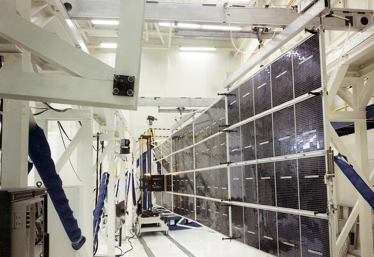
The Apollo Telescope Mount (ATM), one of four major components comprising Skylab, was designed and developed by the Marshall Space Flight Center. Power to operate the ATM's instruments and experiments was collected by four solar arrays, capable of producing up to 1.1 kilowatts of electricity. This is a photograph of the ATM Solar Array flight unit deployed for illumination testing.
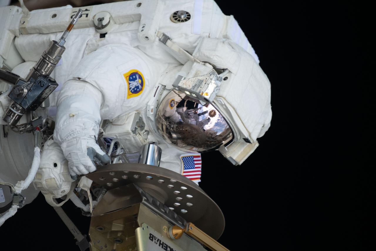
iss070e37241 (Nov. 1, 2023) --- Expedition 70 Flight Engineer and NASA astronaut Loral O'Hara is pictured during a spacewalk for maintenance on the International Space Station's port solar alpha rotary joint, which allows the solar arrays to track the Sun and generate electricity to power the orbital outpost.
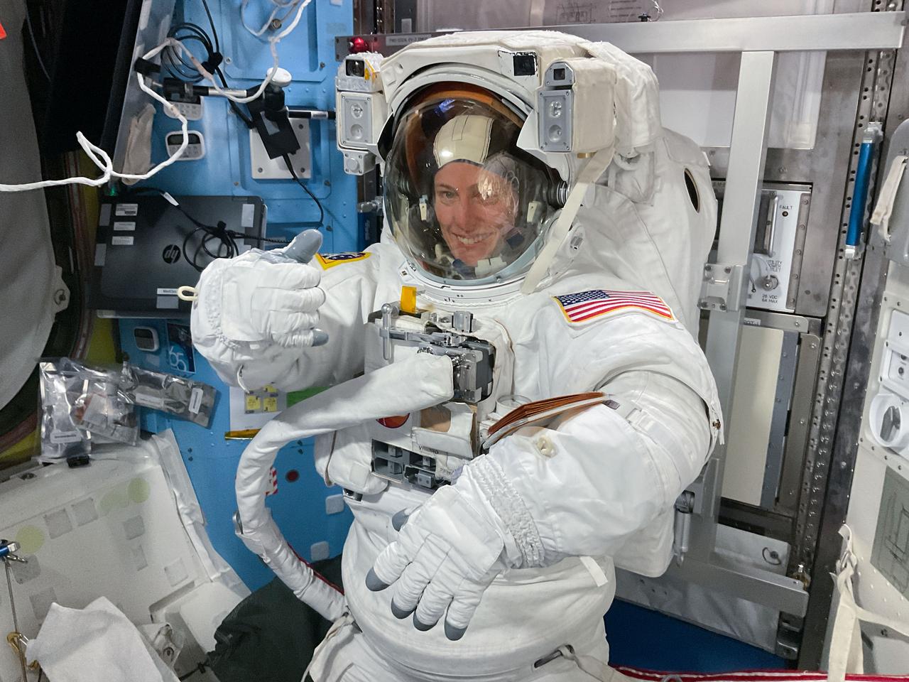
iss070e37272 (Nov. 1, 2023) --- Expedition 70 Flight Engineer and NASA astronaut Loral O'Hara is pictured in her spacesuit before beginning a spacewalk for maintenance on the International Space Station's port solar alpha rotary joint, which allows the solar arrays to track the Sun and generate electricity to power the orbital outpost.
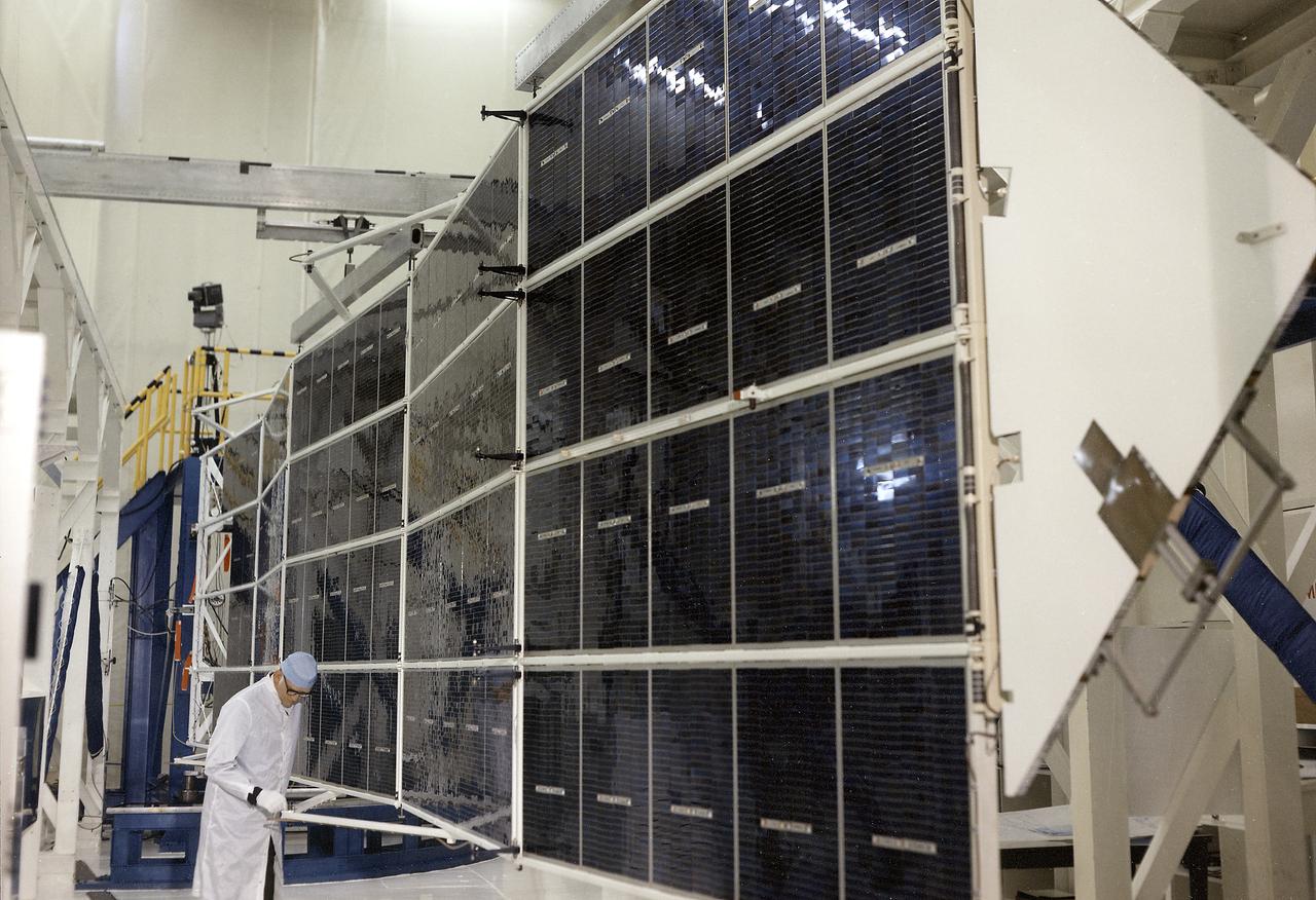
The Apollo Telescope Mount (ATM), one of four major components comprising Skylab, was designed and developed by the Marshall Space Flight Center. Power to operate the ATM's instruments and experiments was collected by four solar arrays, capable of producing up to 1.1 kilowatts of electricity. This is a photograph of the ATM Solar Array flight unit 1 in the deployed position.
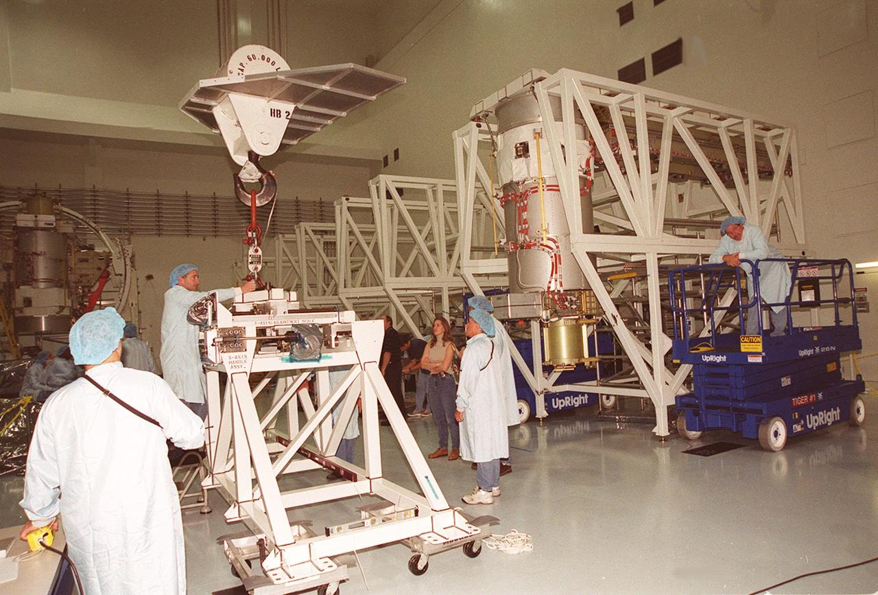
Workers in the Space Station Processing Facility watch closely as Solar Array Wing-3, a component of the International Space Station, is moved toward the Integrated Electronic Assembly where it will be installed for testing. The solar array is scheduled to be launched on STS-97 in late November along with the P6 truss. The Station’s electrical power system (EPS) will use eight photovoltaic solar arrays to convert sunlight to electricity. Each of the eight solar arrays will be 112 feet long by 39 feet wide. The solar arrays are mounted on a “blanket” that can be folded like an accordion for delivery. Once in orbit, astronauts will deploy the blankets to their full size. Gimbals will be used to rotate the arrays so that they will face the Sun to provide maximum power to the Space Station
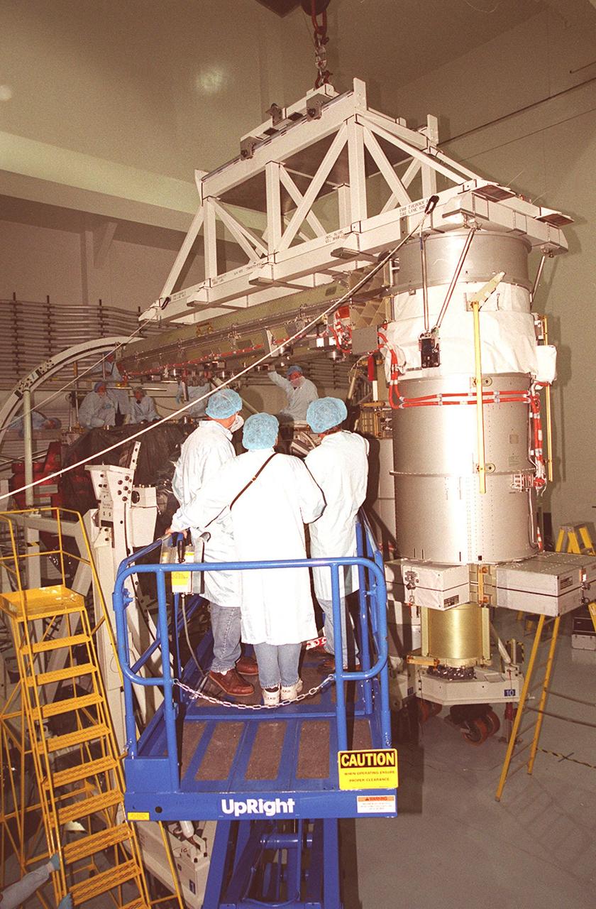
Workers in the Space Station Processing Facility get ready to attach an overhead crane (center top) to the solar array below it to move the array for installation onto the Integrated Equipment Assembly (IEA). A component of the International Space Station, the solar array is the second one being installed on the IEA. The arrays are scheduled to be launched on mission STS-97 in late November along with the P6 truss. The Station’s electrical power system (EPS) will use eight photovoltaic solar arrays to convert sunlight to electricity. Each of the eight solar arrays will be 112 feet long by 39 feet wide. The solar arrays are mounted on a “blanket” that can be folded like an accordion for delivery. Once in orbit, astronauts will deploy the blankets to their full size. Gimbals will be used to rotate the arrays so that they will face the Sun to provide maximum power to the Space Station
Workers in the Space Station Processing Facility prepare an overhead crane they will use to move a solar array, a component of the International Space Station, for installation onto the Integrated Equipment Assembly. The solar array is the second one being installed. They are scheduled to be launched on mission STS-97 in late November along with the P6 truss. The Station’s electrical power system (EPS) will use eight photovoltaic solar arrays to convert sunlight to electricity. Each of the eight solar arrays will be 112 feet long by 39 feet wide. The solar arrays are mounted on a “blanket” that can be folded like an accordion for delivery. Once in orbit, astronauts will deploy the blankets to their full size. Gimbals will be used to rotate the arrays so that they will face the Sun to provide maximum power to the Space Station
In the Space Station Processing Facility, workers help guide a solar array into position for installation on the Integrated Equipment Assembly. Solar Array Wing-3 is already in place. Components of the International Space Station, the arrays are scheduled to be launched on mission STS-97 in late November along with the P6 truss. The Station’s electrical power system (EPS) will use eight photovoltaic solar arrays to convert sunlight to electricity. Each of the eight solar arrays will be 112 feet long by 39 feet wide. The solar arrays are mounted on a “blanket” that can be folded like an accordion for delivery. Once in orbit, astronauts will deploy the blankets to their full size. Gimbals will be used to rotate the arrays so that they will face the Sun to provide maximum power to the Space Station
Workers in the Space Station Processing Facility help guide an overhead crane toward a workstand containing a solar array in order to move it for installation onto the Integrated Equipment Assembly (IEA). A component of the International Space Station, the solar array is the second one being installed on the IEA. The arrays are scheduled to be launched on mission STS-97 in late November along with the P6 truss. The Station’s electrical power system (EPS) will use eight photovoltaic solar arrays to convert sunlight to electricity. Each of the eight solar arrays will be 112 feet long by 39 feet wide. The solar arrays are mounted on a “blanket” that can be folded like an accordion for delivery. Once in orbit, astronauts will deploy the blankets to their full size. Gimbals will be used to rotate the arrays so that they will face the Sun to provide maximum power to the Space Station
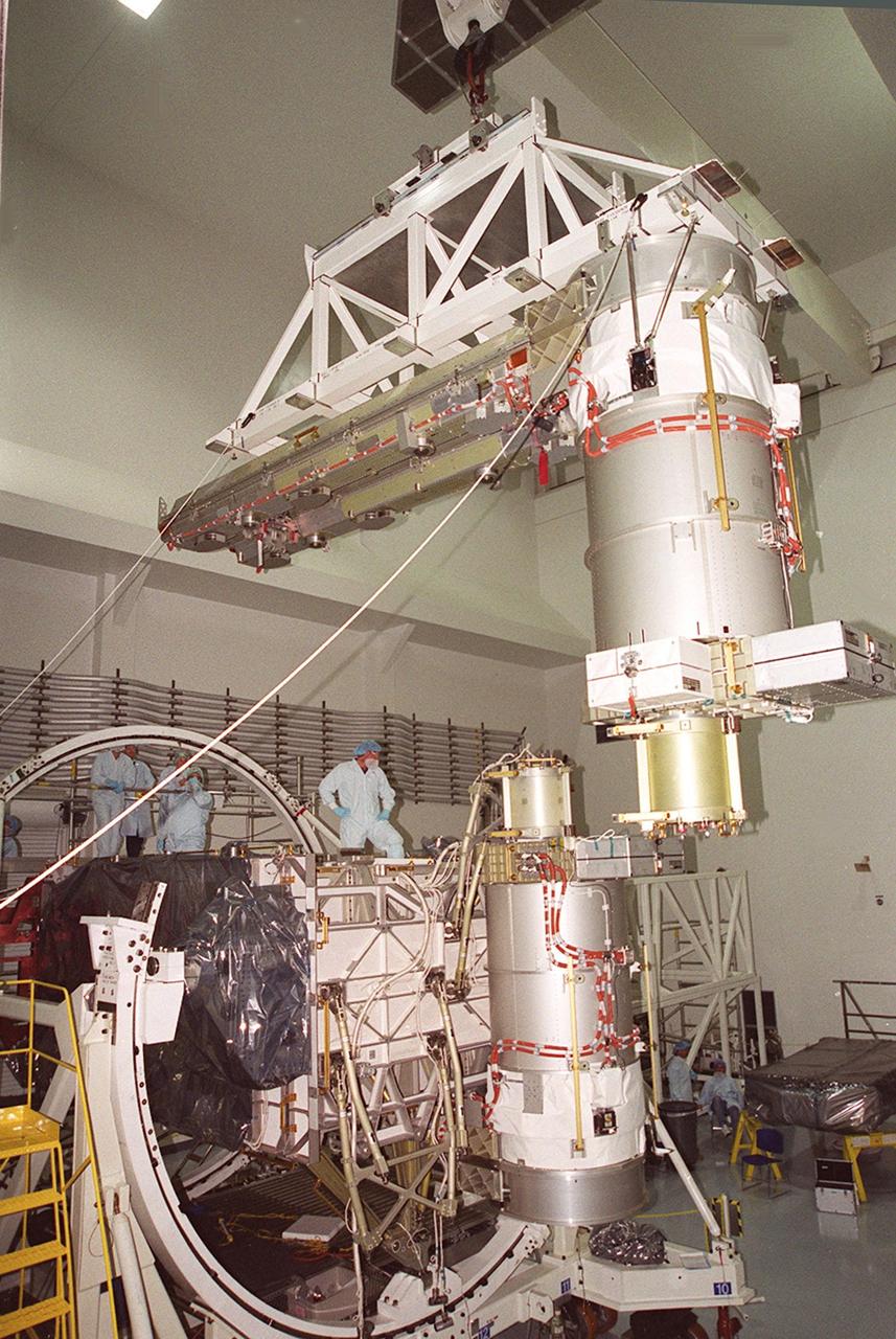
In the Space Station Processing Facility, the overhead crane carrying a solar array arrives at the Integrated Equipment Assembly (IEA) on which it will be installed. Solar Array Wing-3 is already in place. Components of the International Space Station, the arrays are scheduled to be launched on mission STS-97 in late November along with the P6 truss. The Station’s electrical power system (EPS) will use eight photovoltaic solar arrays to convert sunlight to electricity. Each of the eight solar arrays will be 112 feet long by 39 feet wide. The solar arrays are mounted on a “blanket” that can be folded like an accordion for delivery. Once in orbit, astronauts will deploy the blankets to their full size. Gimbals will be used to rotate the arrays so that they will face the Sun to provide maximum power to the Space Station
In the Space Station Processing Facility, the overhead crane carrying a solar array maneuvers its cargo into position on the Integrated Equipment Assembly on which it will be installed. Solar Array Wing-3 is already in place. Components of the International Space Station, the arrays are scheduled to be launched on mission STS-97 in late November along with the P6 truss. The Station’s electrical power system (EPS) will use eight photovoltaic solar arrays to convert sunlight to electricity. Each of the eight solar arrays will be 112 feet long by 39 feet wide. The solar arrays are mounted on a “blanket” that can be folded like an accordion for delivery. Once in orbit, astronauts will deploy the blankets to their full size. Gimbals will be used to rotate the arrays so that they will face the Sun to provide maximum power to the Space Station
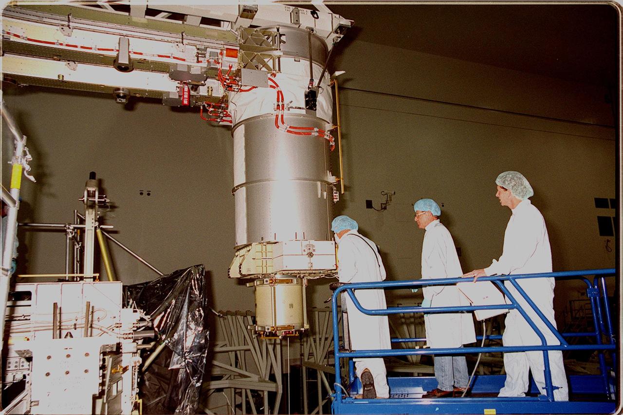
Workers in the Space Station Processing Facility watch closely as Solar Array Wing-3, a component of the International Space Station, is lowered toward the Integrated Electronic Assembly where it will be installed for testing. The solar array is scheduled to be launched on STS-97 in late November along with the P6 truss. The Station’s electrical power system (EPS) will use eight photovoltaic solar arrays to convert sunlight to electricity. Each of the eight solar arrays will be 112 feet long by 39 feet wide. The solar arrays are mounted on a “blanket” that can be folded like an accordion for delivery. Once in orbit, astronauts will deploy the blankets to their full size. Gimbals will be used to rotate the arrays so that they will face the Sun to provide maximum power to the Space Station
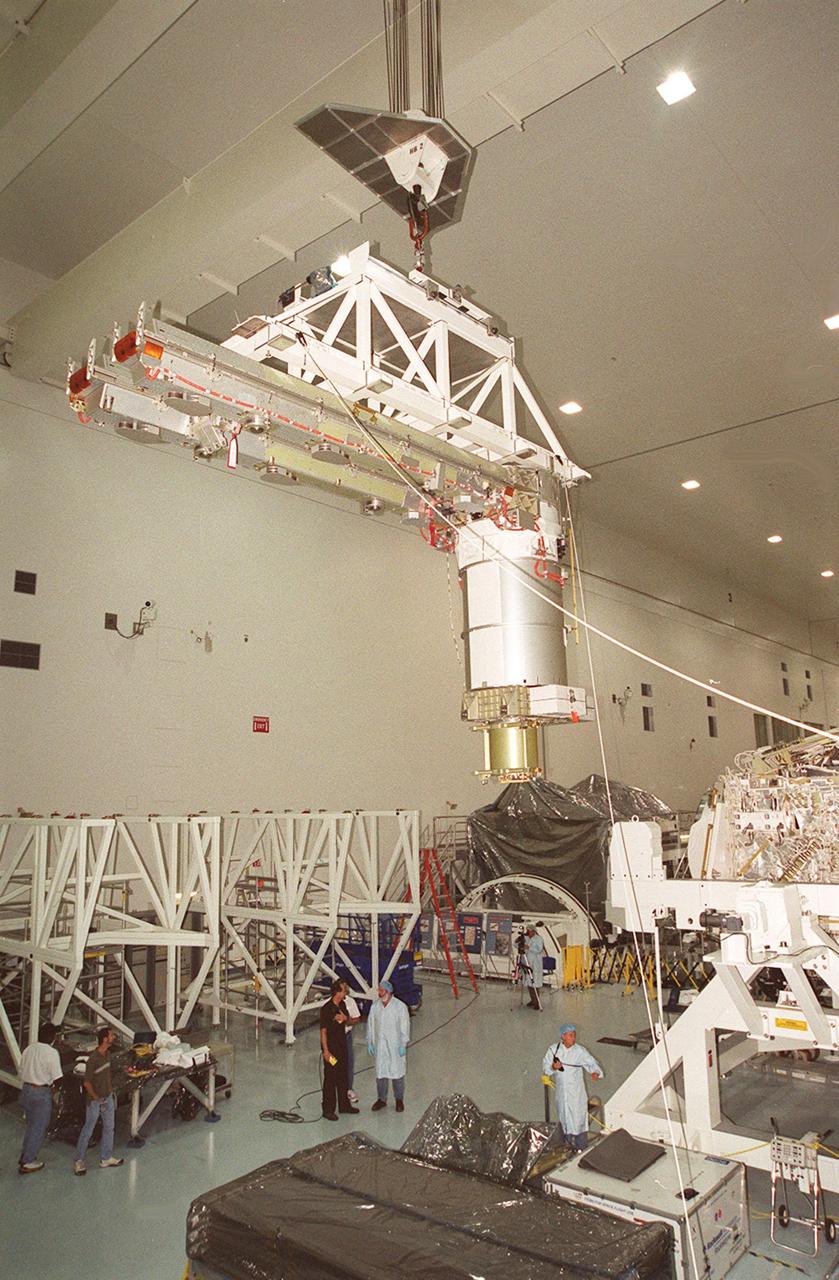
The overhead crane carrying a solar array turns on its axis to move the array to the Integrated Equipment Assembly (IEA) for installation. A component of the International Space Station, the solar array is the second one being installed on the IEA. The arrays are scheduled to be launched on mission STS-97 in late November along with the P6 truss. The Station’s electrical power system (EPS) will use eight photovoltaic solar arrays to convert sunlight to electricity. Each of the eight solar arrays will be 112 feet long by 39 feet wide. The solar arrays are mounted on a “blanket” that can be folded like an accordion for delivery. Once in orbit, astronauts will deploy the blankets to their full size. Gimbals will be used to rotate the arrays so that they will face the Sun to provide maximum power to the Space Station
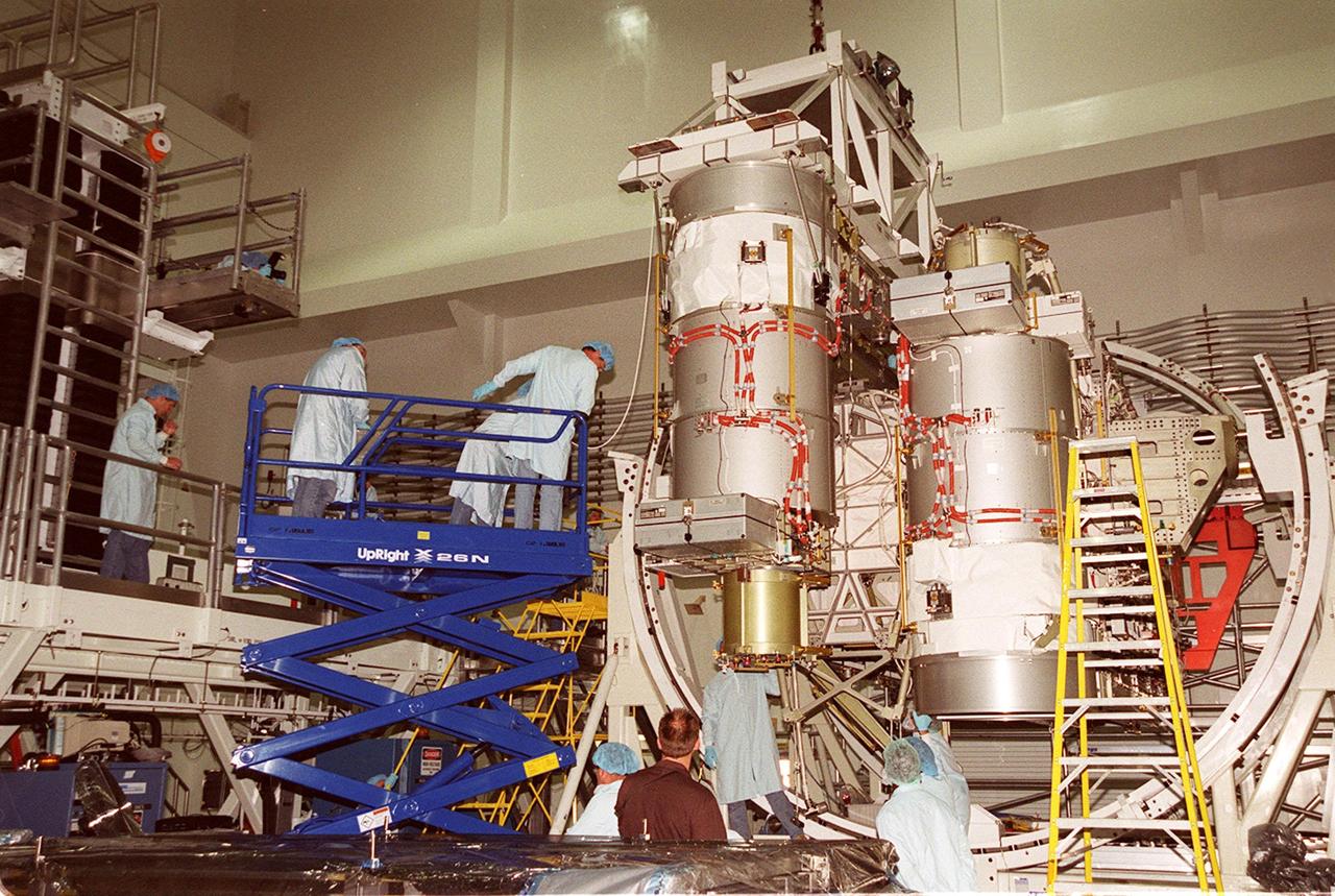
Workers in the Space Station Processing Facility give close attention to the placement of a solar array on the Integrated Equipment Assembly. Solar Array Wing-3 is already in place. Components of the International Space Station, the arrays are scheduled to be launched on mission STS-97 in late November along with the P6 truss. The Station’s electrical power system (EPS) will use eight photovoltaic solar arrays to convert sunlight to electricity. Each of the eight solar arrays will be 112 feet long by 39 feet wide. The solar arrays are mounted on a “blanket” that can be folded like an accordion for delivery. Once in orbit, astronauts will deploy the blankets to their full size. Gimbals will be used to rotate the arrays so that they will face the Sun to provide maximum power to the Space Station
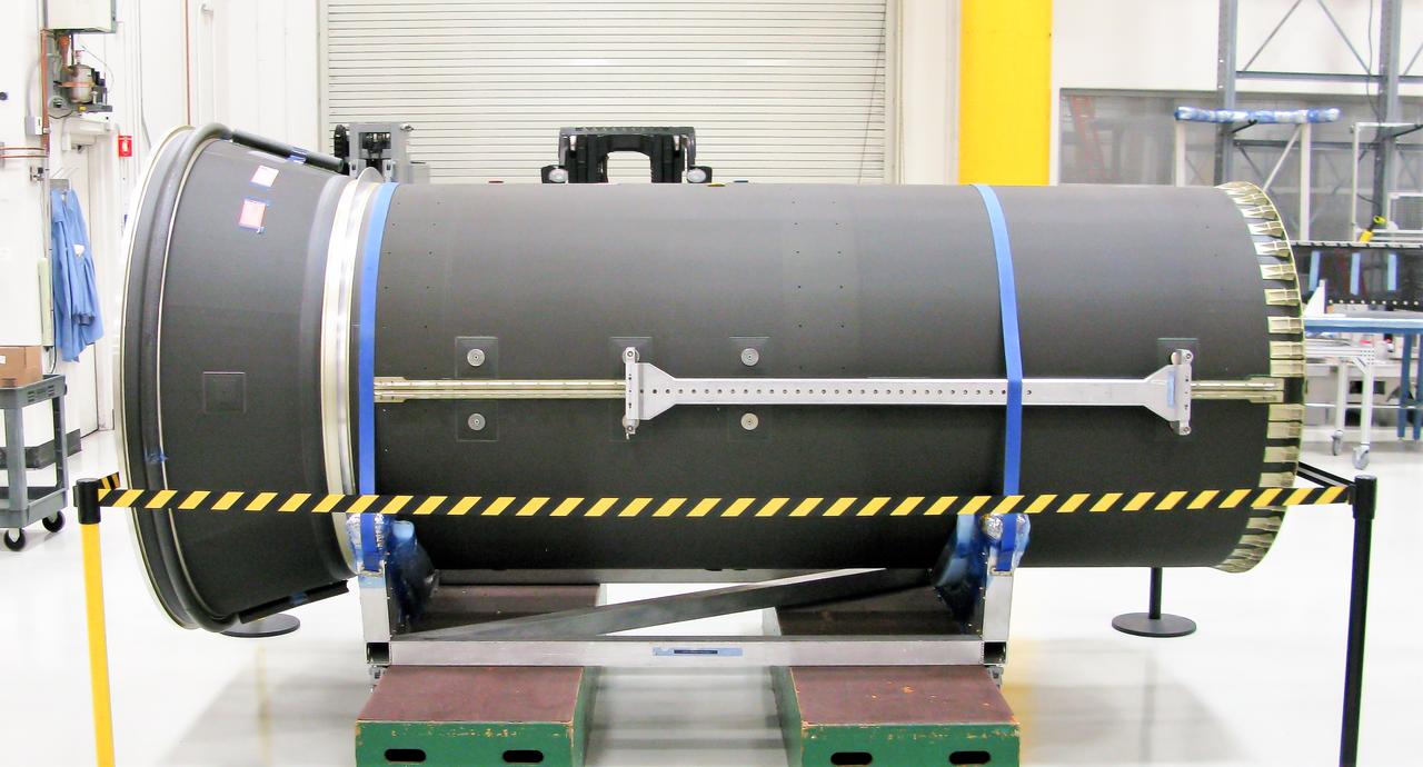
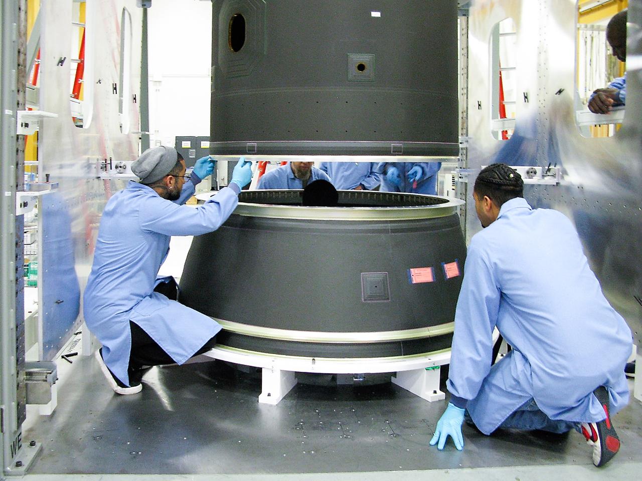
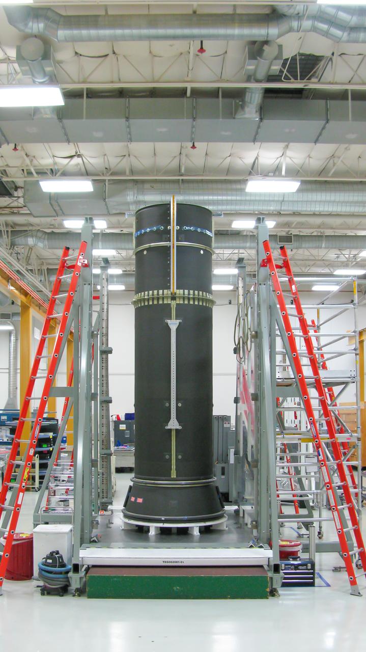
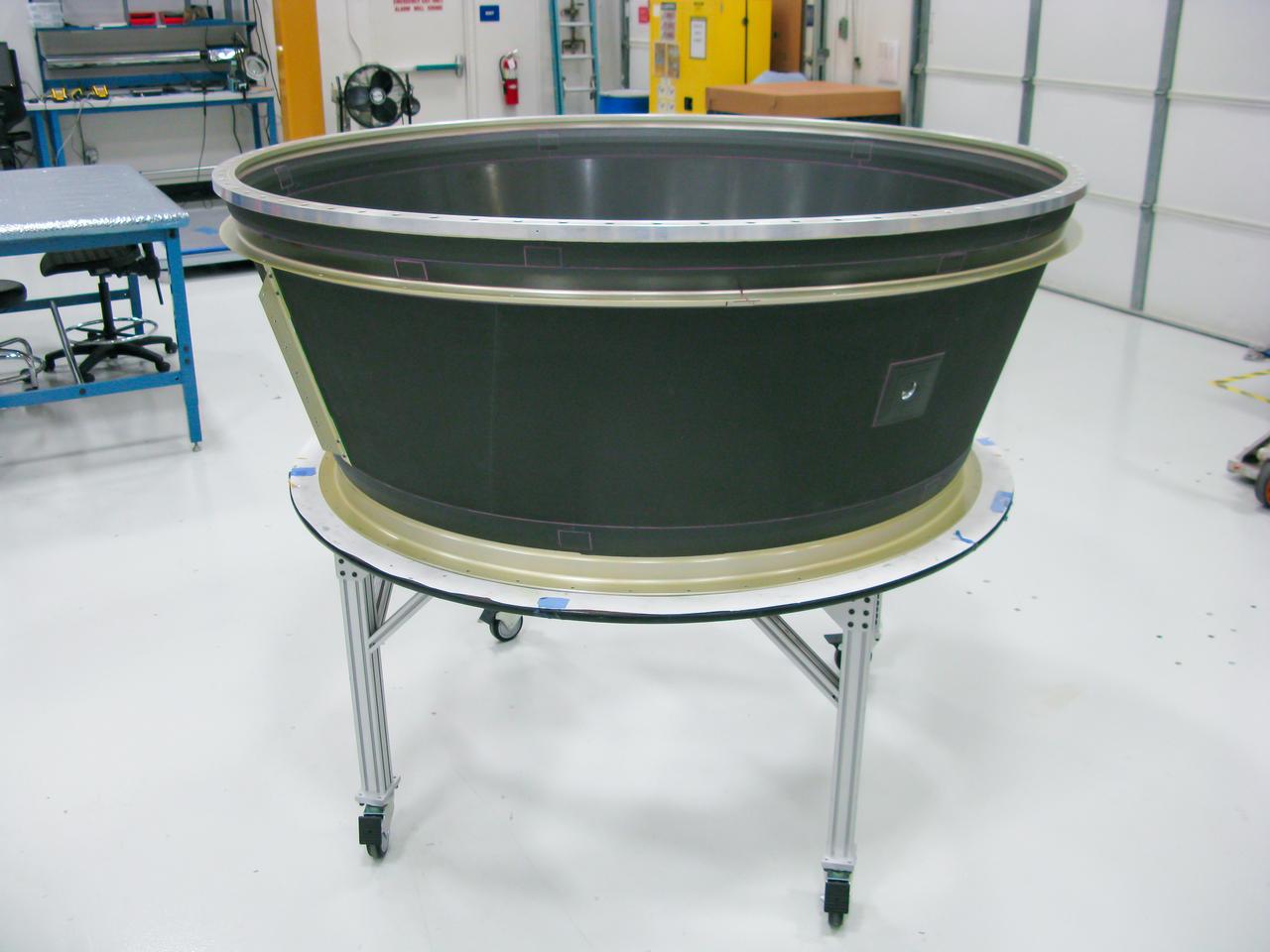
Maxar Technologies completes early fabrication work on the central cylinder structure of the Gateway space station's Power and Propulsion Element (PPE) that will make Gateway the most powerful solar electric spacecraft ever flown.
Maxar Technologies completes early fabrication work on the central cylinder structure of the Gateway space station's Power and Propulsion Element (PPE) that will make Gateway the most powerful solar electric spacecraft ever flown.
Maxar Technologies completes early fabrication work on the central cylinder structure of the Gateway space station's Power and Propulsion Element (PPE) that will make Gateway the most powerful solar electric spacecraft ever flown.
Maxar Technologies completes early fabrication work on the central cylinder structure of the Gateway space station's Power and Propulsion Element (PPE) that will make Gateway the most powerful solar electric spacecraft ever flown.
Maxar Technologies completes early fabrication work on the central cylinder structure of the Gateway space station's Power and Propulsion Element (PPE) that will make Gateway the most powerful solar electric spacecraft ever flown.
Maxar Technologies completes early fabrication work on the central cylinder structure of the Gateway space station's Power and Propulsion Element (PPE) that will make Gateway the most powerful solar electric spacecraft ever flown.

Maxar Technologies completes early fabrication work on the central cylinder structure of the Gateway space station's Power and Propulsion Element (PPE) that will make Gateway the most powerful solar electric spacecraft ever flown.
Maxar Technologies completes early fabrication work on the central cylinder structure of the Gateway space station's Power and Propulsion Element (PPE) that will make Gateway the most powerful solar electric spacecraft ever flown.
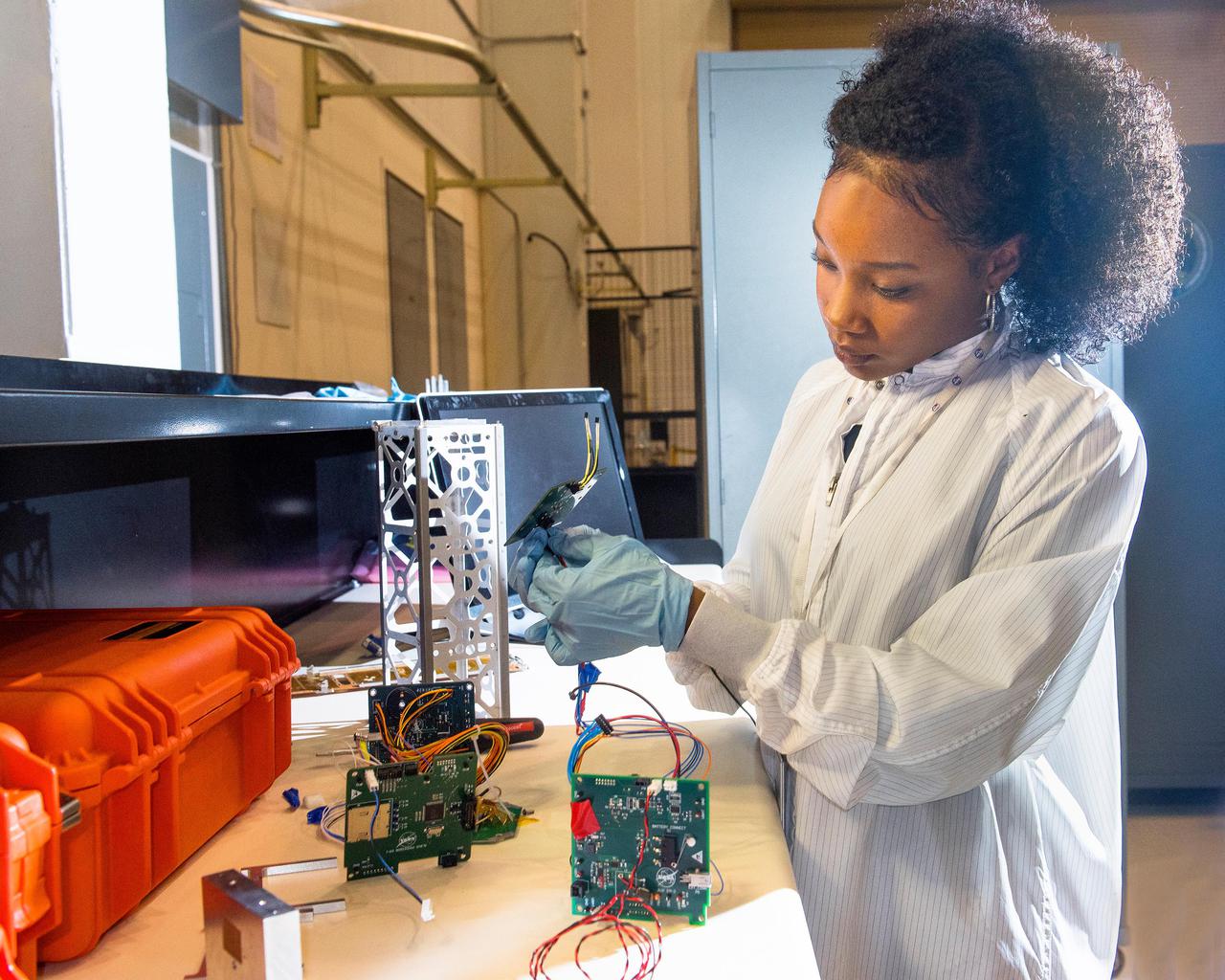
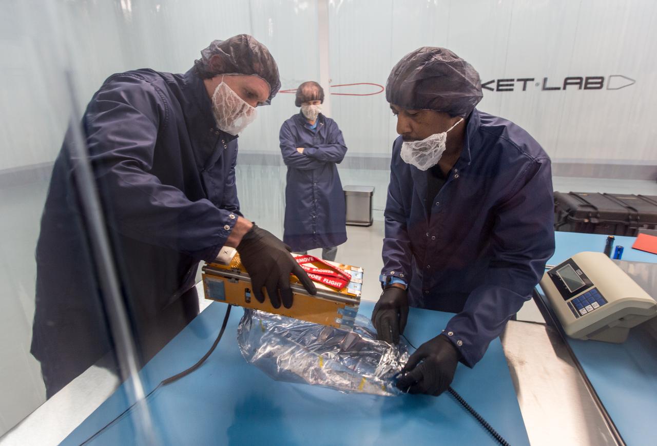
Advanced eLectrical Bus (ALBus) CubeSat: From Build to Flight A new CubeSat, launched Sunday, December 16, will test high power electric systems and the use of unique shape memory alloy (SMA) components for the first time. CubeSats are very small, lightweight satellites, about the size of a loaf of bread, and typically operate within a power range of 5-20 watts. Lower power systems are typically used in CubeSats because of size and weight limits, while higher power systems and components cause excessive heat. Completely designed and led by a team of 12 early career scientists and engineers at NASA’s Glenn Research Center in Cleveland, the Advanced Electrical Bus, or ALBus, will be the first CubeSat to demonstrate power management and distribution of a 100-watt electrical system. The CubeSat will also employ a custom-built SMA release mechanism and hinges to deploy solar arrays and conduct electricity.

STS097-S-001 (January 2000) --- This is the crew insignia for STS-97, which will deliver, assemble, and activate the U.S. electrical power system on board the International Space Station (ISS). The electrical power system, which is built into a 47-foot integrated truss structure known as P6, consists of solar arrays, radiators, batteries, and electronics. P6 will be attached to the station using the shuttle's robotic arm in coordination with spacewalking crew members that will make the final connections. The spacewalkers will then prepare P6 for the subsequent deployments of the large solar arrays and radiator, which are critical steps in the activation of the electrical power system. The 120-foot solar arrays will provide the power necessary for the first ISS crews to live and work in the U.S. segment. The crew patch depicts the space shuttle docked to ISS in low Earth orbit after the activation of the P6 electrical power system. Gold and silver are used to highlight the portion of ISS that will be installed by the STS-97 crew. The Sun, central to the design, is the source of energy for ISS. The NASA insignia design for space shuttle flights is reserved for use by the astronauts and for other official use as the NASA Administrator may authorize. Public availability has been approved only in the forms of illustrations by the various news media. When and if there is any change in this policy, which is not anticipated, the change will be publicly announced. Photo credit: NASA
CAPE CANAVERAL, Fla. – This map shows the area within NASA's Kennedy Space Center where one of the two solar photovoltaic power generation systems will be built as the result of an agreement between NASA and Florida Power & Light. The agreement is part of a new initiative that will cut reliance on fossil fuels and improve the environment by reducing greenhouse gas emissions. The major facility will produce an estimated 10 megawatts of electrical power, which can serve roughly 3,000 homes. A separate one-megawatt solar power facility will support the electrical needs of the center.
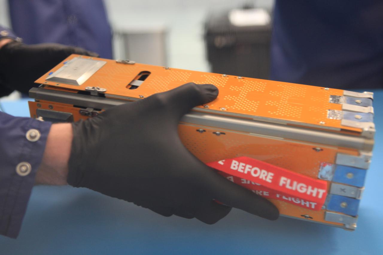
The Advanced Electrical Bus (ALBus) mission is a technology demonstration of resettable Shape Memory Alloy (SMA) mechanisms for deployable solar arrays and a pathfinder for high power density CubeSats. The mission has two primary objectives. The first is to demonstrate the functionality of the novel SMA activated solar array mechanisms in the on-orbit environment. The second objective is to assess the system level ability to charge a high capacity battery, distribute 100 W of electrical power and thermally control the 3-U CubeSat system. Performance from the mission will be used to mature the SMA mechanism designs for CubeSat applications and plan for future high power density CubeSat missions.
The Advanced Electrical Bus (ALBus) mission is a technology demonstration of resettable Shape Memory Alloy (SMA) mechanisms for deployable solar arrays and a pathfinder for high power density CubeSats. The mission has two primary objectives. The first is to demonstrate the functionality of the novel SMA activated solar array mechanisms in the on-orbit environment. The second objective is to assess the system level ability to charge a high capacity battery, distribute 100 W of electrical power and thermally control the 3-U CubeSat system. Performance from the mission will be used to mature the SMA mechanism designs for CubeSat applications and plan for future high power density CubeSat missions.
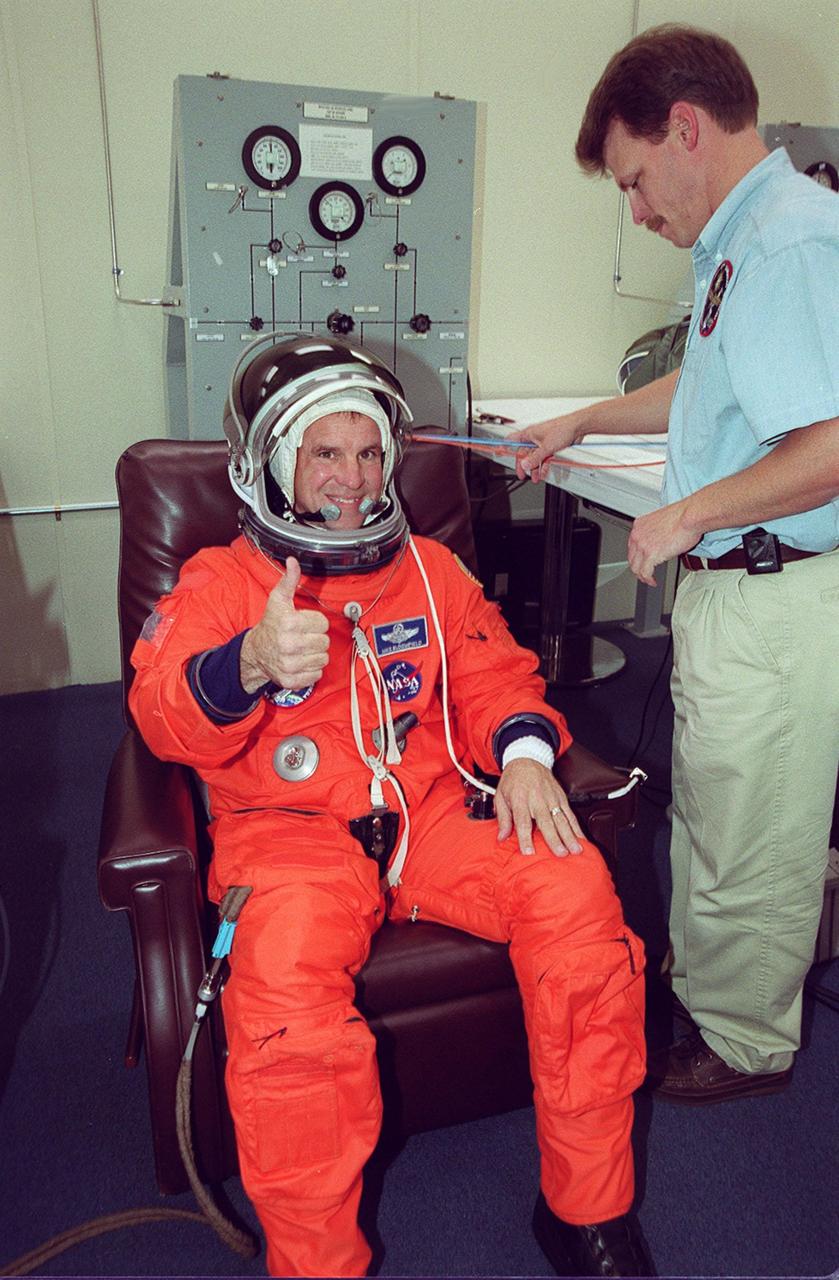
STS-97 Pilot Michael Bloomfield signals thumbs up for launch after donning his launch and entry suit. This is his second Shuttle flight. Mission STS-97 is the sixth construction flight to the International Space Station. It is transporting the P6 Integrated Truss Structure that comprises Solar Array Wing-3 and the Integrated Electronic Assembly, to be installed on the Space Station. The solar arrays are mounted on a “blanket” that can be folded like an accordion for delivery. Once in orbit, astronauts will deploy the blankets to their full size. The 11-day mission includes two spacewalks to complete the solar array connections. The Station’s electrical power system will use eight photovoltaic solar arrays, each 112 feet long by 39 feet wide, to convert sunlight to electricity. Gimbals will be used to rotate the arrays so that they will face the Sun to provide maximum power to the Space Station. Launch is scheduled for Nov. 30 at 10:06 p.m. EST
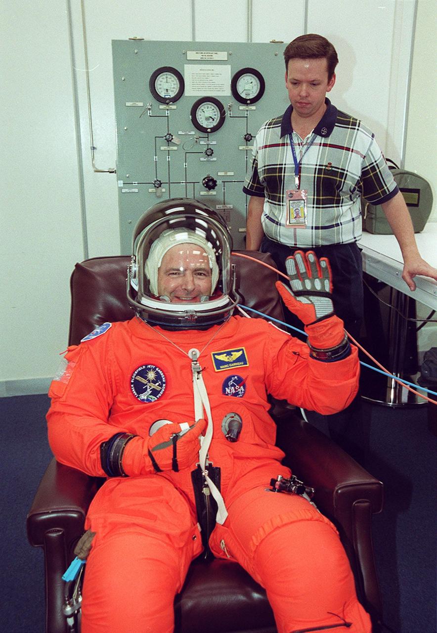
STS-97 Mission Specialist Marc Garneau, who is with the Canadian Space Agency, waves after donning his launch and entry suit. This is his third Shuttle flight.; Mission STS-97 is the sixth construction flight to the International Space Station. It is transporting the P6 Integrated Truss Structure that comprises Solar Array Wing-3 and the Integrated Electronic Assembly, to be installed on the Space Station. The solar arrays are mounted on a “blanket” that can be folded like an accordion for delivery. Once in orbit, astronauts will deploy the blankets to their full size. The 11-day mission includes two spacewalks to complete the solar array connections. The Station’s electrical power system will use eight photovoltaic solar arrays, each 112 feet long by 39 feet wide, to convert sunlight to electricity.. Gimbals will be used to rotate the arrays so that they will face the Sun to provide maximum power to the Space Station. Launch is scheduled for Nov. 30 at 10:06 p.m. EST

STS-97 Mission Specialist Carlos Noriega appears relaxed as he dons his launch and entry suit. This is his second Shuttle flight. Mission STS-97 is the sixth construction flight to the International Space Station. It is transporting the P6 Integrated Truss Structure that comprises Solar Array Wing-3 and the Integrated Electronic Assembly, to be installed on the Space Station. The solar arrays are mounted on a “blanket” that can be folded like an accordion for delivery. Once in orbit, astronauts will deploy the blankets to their full size. The 11-day mission includes two spacewalks to complete the solar array connections. The Station’s electrical power system will use eight photovoltaic solar arrays, each 112 feet long by 39 feet wide, to convert sunlight to electricity. Gimbals will be used to rotate the arrays so that they will face the Sun to provide maximum power to the Space Station. Launch is scheduled for Nov. 30 at 10:06 p.m. EST
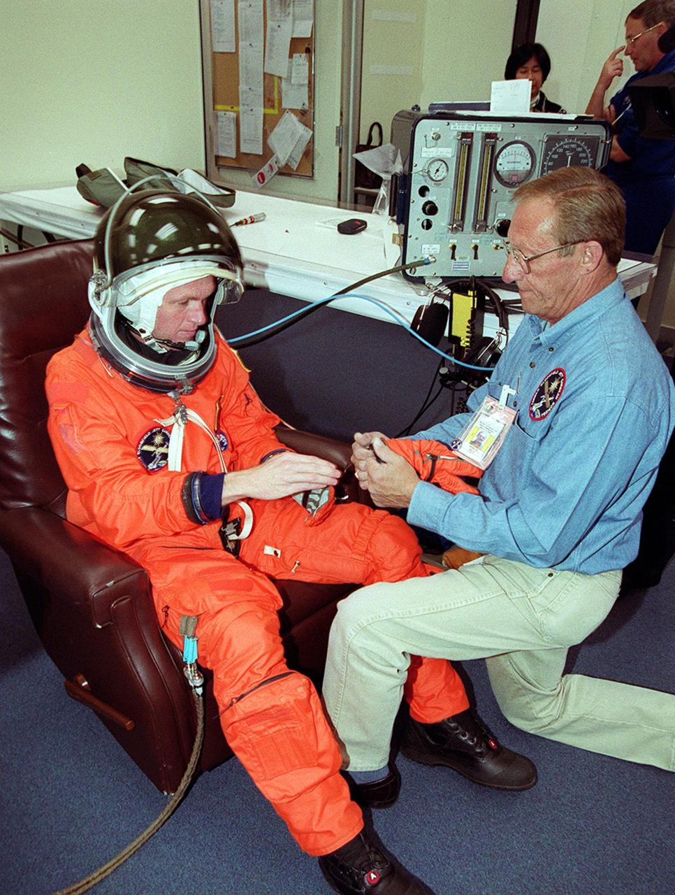
With the help of a suit technician, STS-97 Commander Brent Jett dons his launch and entry suit. This is his third Shuttle flight.; Mission STS-97 is the sixth construction flight to the International Space Station. It is transporting the P6 Integrated Truss Structure that comprises Solar Array Wing-3 and the Integrated Electronic Assembly, to be installed on the Space Station. The solar arrays are mounted on a “blanket” that can be folded like an accordion for delivery. Once in orbit, astronauts will deploy the blankets to their full size. The 11-day mission includes two spacewalks to complete the solar array connections. The Station’s electrical power system will use eight photovoltaic solar arrays, each 112 feet long by 39 feet wide, to convert sunlight to electricity. Gimbals will be used to rotate the arrays so that they will face the Sun to provide maximum power to the Space Station. Launch is scheduled for Nov. 30 at 10:06 p.m. EST
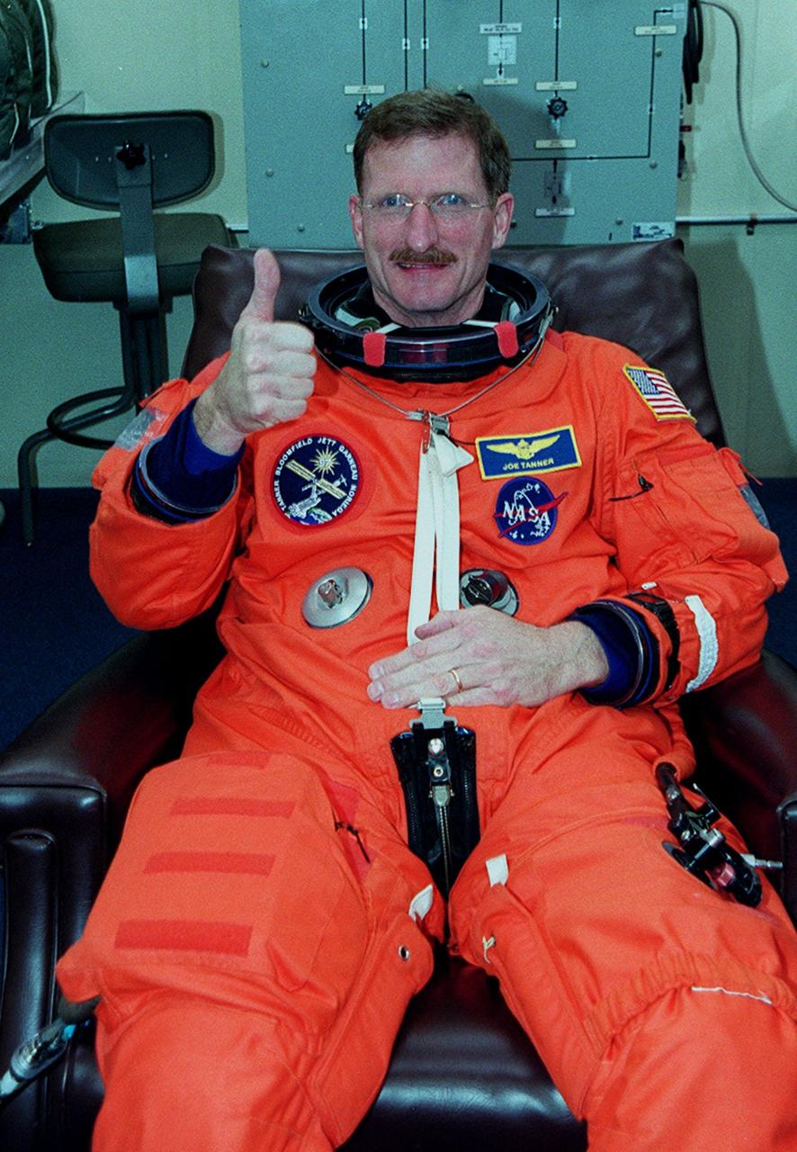
STS-97 Mission Specialist Joseph Tanner signals thumbs up for launch as he dons his launch and entry suit. this is his third Shuttle flight.; Mission STS-97 is the sixth construction flight to the International Space Station. It is transporting the P6 Integrated Truss Structure that comprises Solar Array Wing-3 and the Integrated Electronic Assembly, to be installed on the Space Station. The solar arrays are mounted on a “blanket” that can be folded like an accordion for delivery. Once in orbit, astronauts will deploy the blankets to their full size. The 11-day mission includes two spacewalks to complete the solar array connections. The Station’s electrical power system will use eight photovoltaic solar arrays, each 112 feet long by 39 feet wide, to convert sunlight to electricity.. Gimbals will be used to rotate the arrays so that they will face the Sun to provide maximum power to the Space Station. Launch is scheduled for Nov. 30 at 10:06 p.m. EST
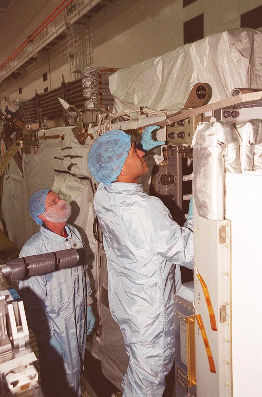
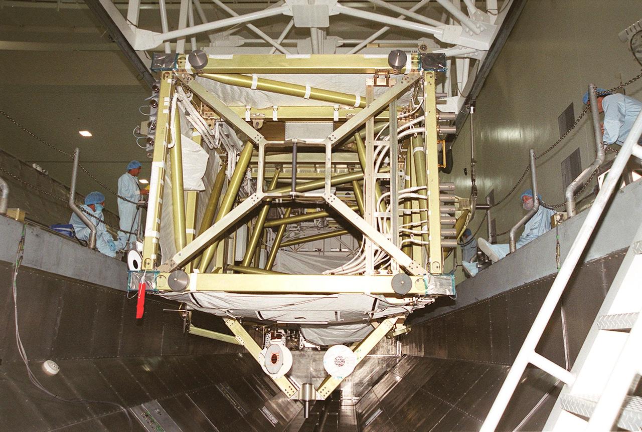
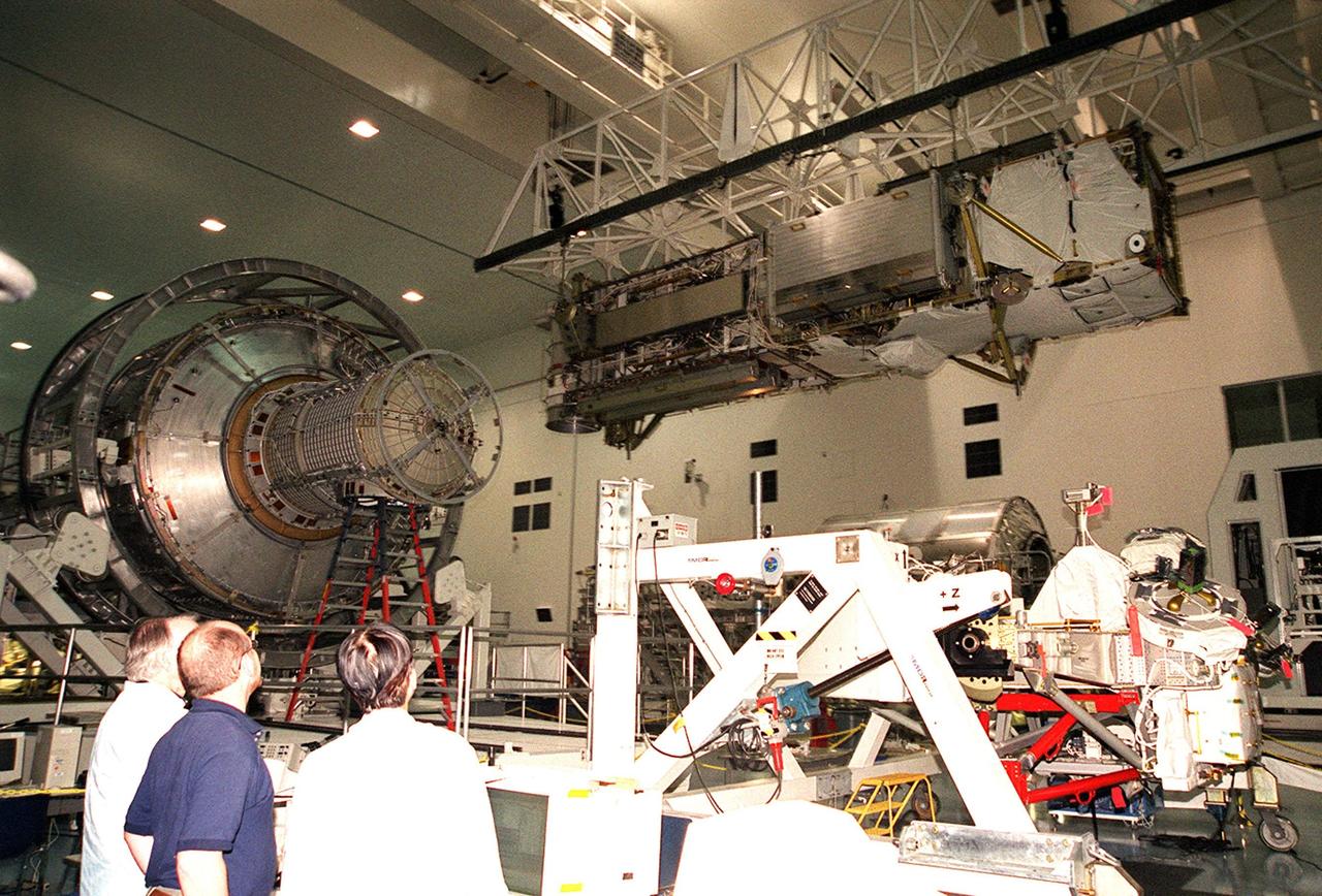
In the Space Station Processing Facility, STS-97 Mission Specialists Carlos Noriega (left) and Joe Tanner check out the mission payload, the P6 integrated truss segment. Mission STS-97 is the sixth construction flight to the International Space Station. The P6 comprises Solar Array Wing-3 and the Integrated Electronic Assembly, to be installed on the International Space Station. The Station’s electrical power system will use eight photovoltaic solar arrays, each 112 feet long by 39 feet wide, to convert sunlight to electricity. The solar arrays are mounted on a “blanket” that can be folded like an accordion for delivery. Once in orbit, astronauts will deploy the blankets to their full size. Gimbals will be used to rotate the arrays so that they will face the Sun to provide maximum power to the Space Station. The mission includes two spacewalks by Noriega and Tanner to complete the solar array connections. STS-97 is scheduled to launch Nov. 30 at about 10:06 p.m. EST
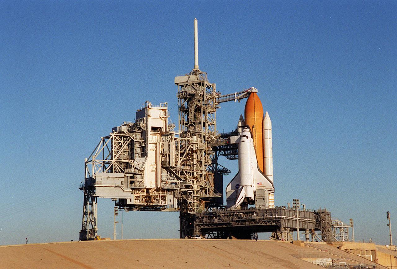
Back dropped by a cloudless blue sky, Space Shuttle Endeavor stands ready for launch after the rollback of the Rotating Service Structure, at left. The orbiter launched that night carrying the STS-97 crew of five. The STS-97 mission's primary objective was the delivery, assembly, and activation of the U.S. electrical power system onboard the International Space Station (ISS). The electrical power system, which is built into a 73-meter (240-foot) long solar array structure, consists of solar arrays, radiators, batteries, and electronics. The entire 15.4-metric ton (17-ton) package is called the P6 Integrated Truss Segment, and is the heaviest and largest element yet delivered to the station aboard a space shuttle. The electric system will eventually provide the power necessary for the first ISS crews to live and work in the U.S. segment.
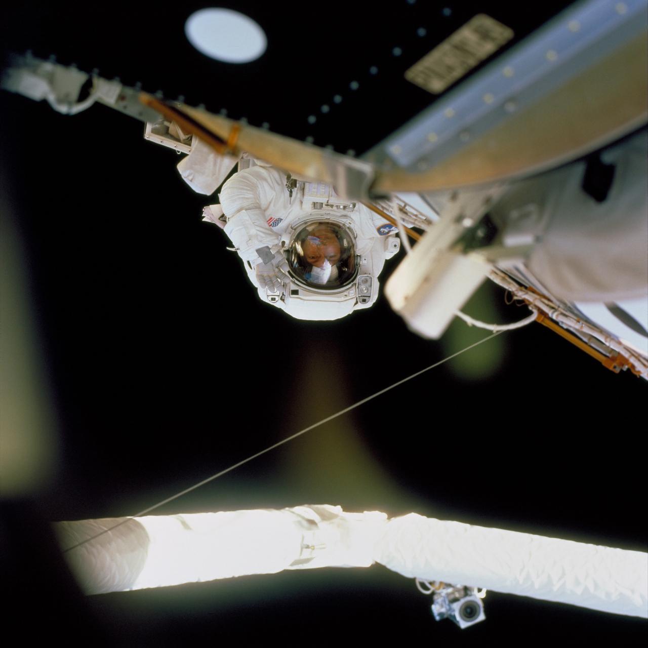
In this image, STS-97 astronaut and mission specialist Carlos I. Noriega waves at a crew member inside Endeavor's cabin during the mission's final session of Extravehicular Activity (EVA). Launched aboard the Space Shuttle Orbiter Endeavor on November 30, 2000, the STS-97 mission's primary objective was the delivery, assembly, and activation of the U.S. electrical power system onboard the International Space Station (ISS). The electrical power system, which is built into a 73-meter (240-foot) long solar array structure consists of solar arrays, radiators, batteries, and electronics. The entire 15.4-metric ton (17-ton) package is called the P6 Integrated Truss Segment, and is the heaviest and largest element yet delivered to the station aboard a space shuttle. The electrical system will eventually provide the power necessary for the first ISS crews to live and work in the U.S. segment.
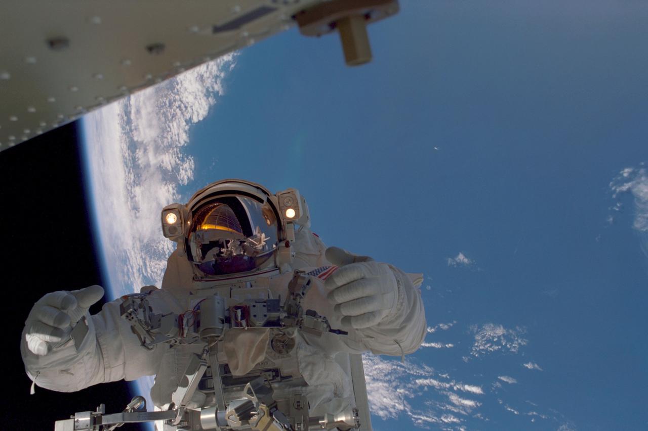
In this image, planet Earth, some 235 statute miles away, forms the back drop for this photo of STS-97 astronaut and mission specialist Joseph R. Tanner, taken during the third of three space walks. The mission's goal was to perform the delivery, assembly, and activation of the U.S. electrical power system onboard the International Space Station (ISS). The electrical power system, which is built into a 73-meter (240-foot) long solar array structure consists of solar arrays, radiators, batteries, and electronics. The entire 15.4-metric ton (17-ton) package is called the P6 Integrated Truss Segment, and is the heaviest and largest element yet delivered to the station aboard a space shuttle. The electrical system will eventually provide the power necessary for the first ISS crews to live and work in the U.S. segment. The STS-97 crew of five launched aboard the Space Shuttle Orbiter Endeavor on November 30, 2000 for an 11 day mission.
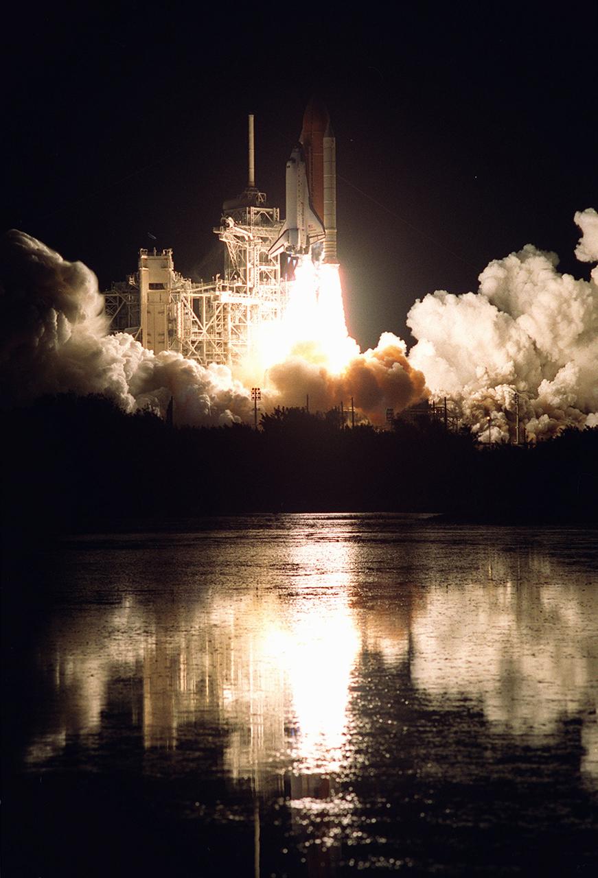
Nearby waters reflect the flames of the Space Shuttle Endeavor as she lifts off November 30, 2000, carrying the STS-97 crew of five. The STS-97 mission's primary objective was the delivery, assembly, and activation of the U.S. electrical power system onboard the International Space Station (ISS). The electrical power system, which is built into a 73-meter (240-foot) long solar array structure, consists of solar arrays, radiators, batteries, and electronics. The entire 15.4-metric ton (17-ton) package is called the P6 Integrated Truss Segment and is the heaviest and largest element yet delivered to the station aboard a space shuttle. The electrical system will eventually provide the power necessary for the first ISS crews to live and work in the U.S. segment.
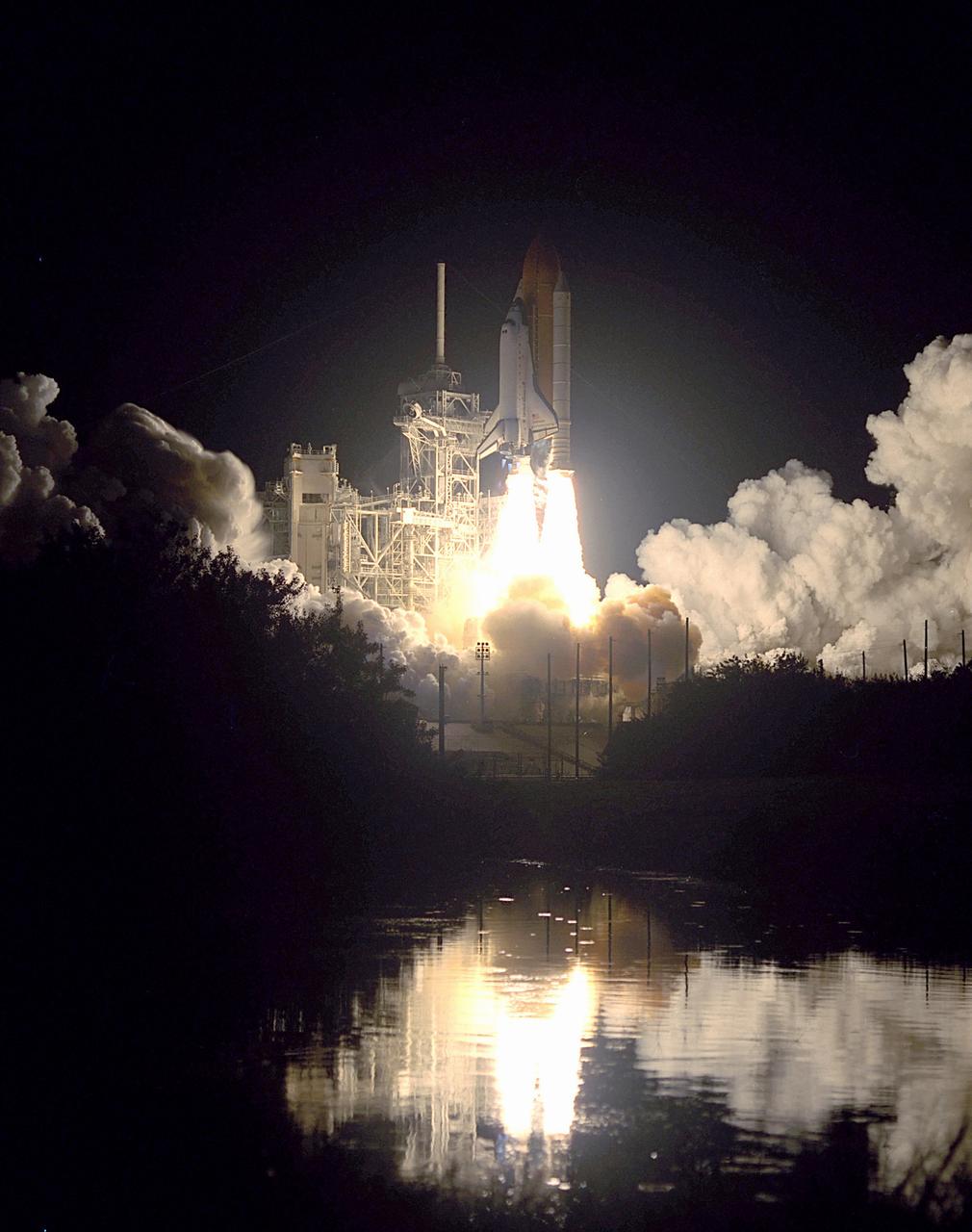
Nearby waters reflect the flames of the Space Shuttle Endeavor as she lifts off November 30, 2000 carrying the STS-97 crew of five. The STS-97 mission's primary objective was the delivery, assembly, and activation of the U.S. electrical power system onboard the International Space Station (ISS). The electrical power system, which is built into a 73-meter (240-foot) long solar array structure, consists of solar arrays, radiators, batteries, and electronics. The entire 15.4-metric ton (17-ton) package is called the P6 Integrated Truss Segment, and is the heaviest and largest element yet delivered to the station aboard a space shuttle. The electrical system will eventually provide the power necessary for the first ISS crews to live and work in the U.S. segment.
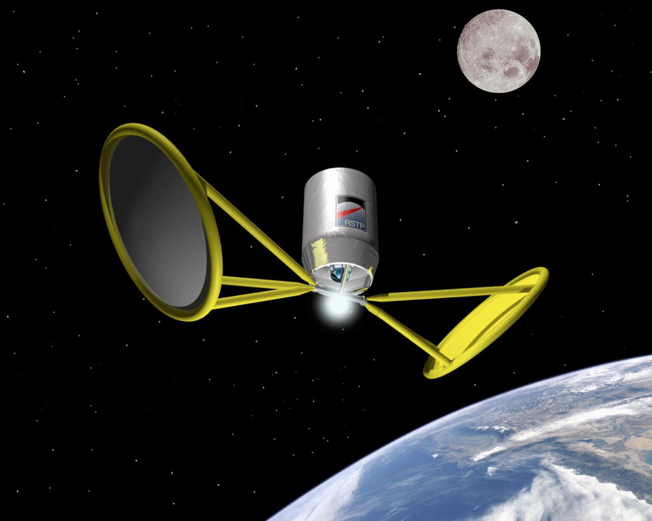
Harnessing the Sun's energy through Solar Thermal Propulsion will propel vehicles through space by significantly reducing weight, complexity, and cost while boosting performance over current conventional upper stages. Another solar powered system, solar electric propulsion, demonstrates ion propulsion is suitable for long duration missions. Pictured is an artist's concept of space flight using solar thermal propulsion.
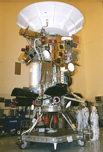
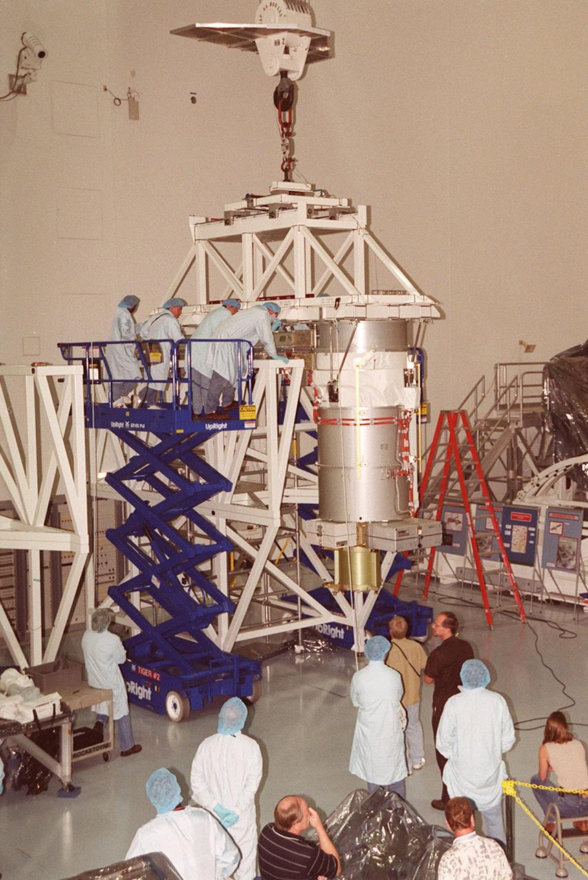
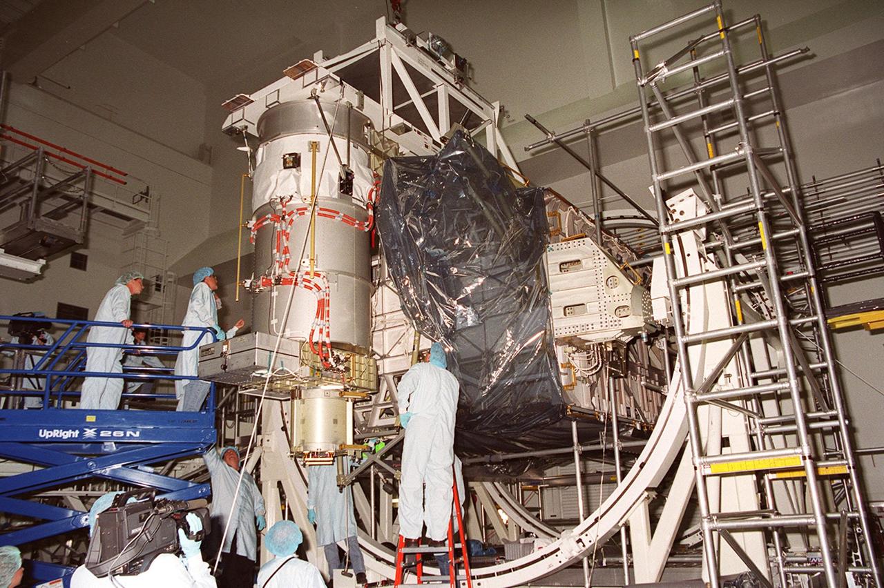
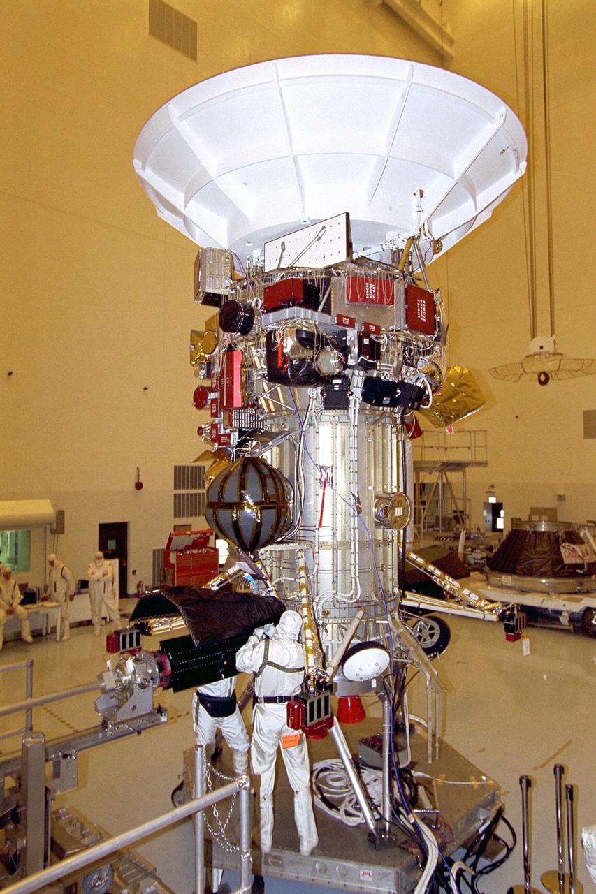
Jet Propulsion Research Lab (JPL) workers use a borescope to verify the pressure relief device bellow's integrity on a radioisotope thermoelectric generator (RTG) that has been installed on the Cassini spacecraft in the Payload Hazardous Servicing Facility. The activity is part of the mechanical and electrical verification testing of RTGs during prelaunch processing. RTGs use heat from the natural decay of plutonium to generate electrical power. The three RTGs on Cassini will enable the spacecraft to operate far from the Sun where solar power systems are not feasible. They will provide electrical power to Cassini on it seven year trip to the Saturnian system and during its four year mission at Saturn.
Jet Propulsion Research Lab (JPL) workers use a borescope to verify the pressure relief device bellow's integrity on a radioisotope thermoelectric generator (RTG) that has been installed on the Cassini spacecraft in the Payload Hazardous Servicing Facility. The activity is part of the mechanical and electrical verification testing of RTGs during prelaunch processing. RTGs use heat from the natural decay of plutonium to generate electrical power. The three RTGs on Cassini will enable the spacecraft to operate far from the Sun where solar power systems are not feasible. They will provide electrical power to Cassini on it seven year trip to the Saturnian system and during its four year mission at Saturn.
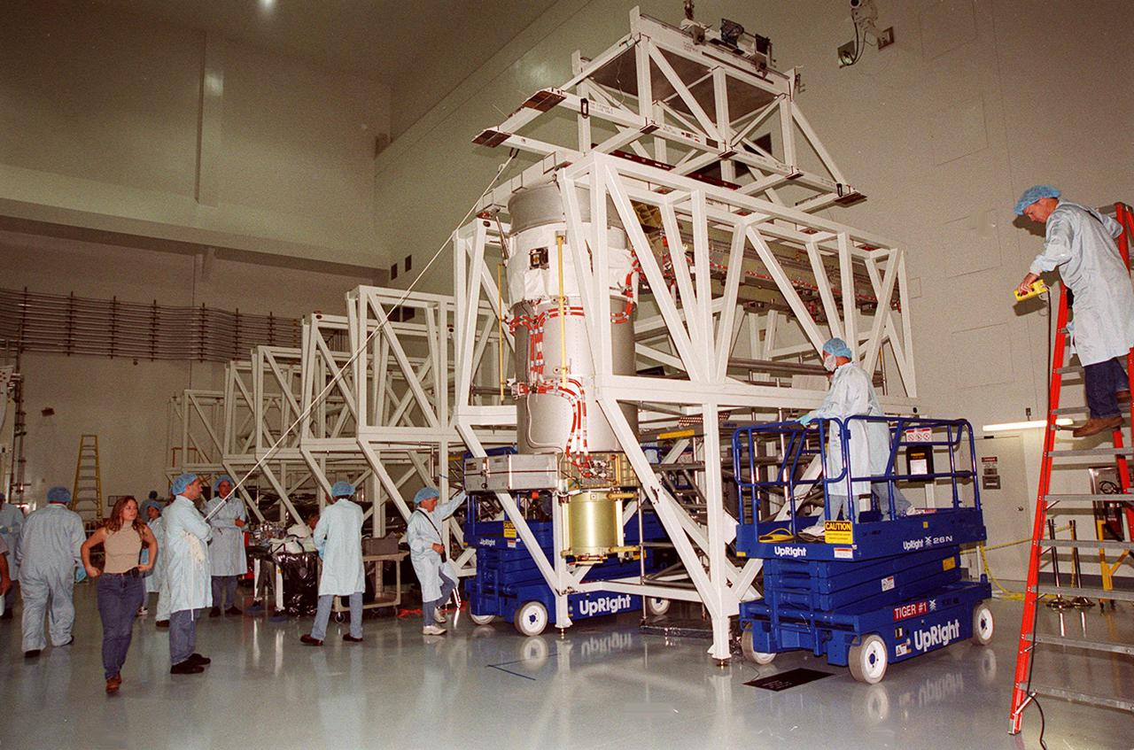
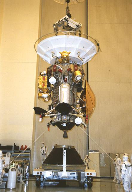
Workers in the Payload Hazardous Servicing Facility remove the storage collar from a radioisotope thermoelectric generator (RTG) in preparation for installation on the Cassini spacecraft. Cassini will be outfitted with three RTGs. The power units are undergoing mechanical and electrical verification tests in the PHSF. The RTGs will provide electrical power to Cassini on its 6.7-year trip to the Saturnian system and during its four-year mission at Saturn. RTGs use heat from the natural decay of plutonium to generate electric power. The generators enable spacecraft to operate at great distances from the Sun where solar power systems are not feasible. The Cassini mission is targeted for an Oct. 6 launch aboard a Titan IVB/Centaur expendable launch vehicle
Jet Propulsion Laboratory (JPL) workers Dan Maynard and John Shuping prepare to install a radioisotope thermoelectric generator (RTG) on the Cassini spacecraft in the Payload Hazardous Servicing Facility (PHSF). The three RTGs which will provide electrical power to Cassini on its mission to the Saturnian system are undergoing mechanical and electrical verification testing in the PHSF. RTGs use heat from the natural decay of plutonium to generate electric power. The generators enable spacecraft to operate far from the Sun where solar power systems are not feasible. The Cassini mission is scheduled for an Oct. 6 launch aboard a Titan IVB/Centaur expendable launch vehicle. Cassini is built and managed for NASA by JPL
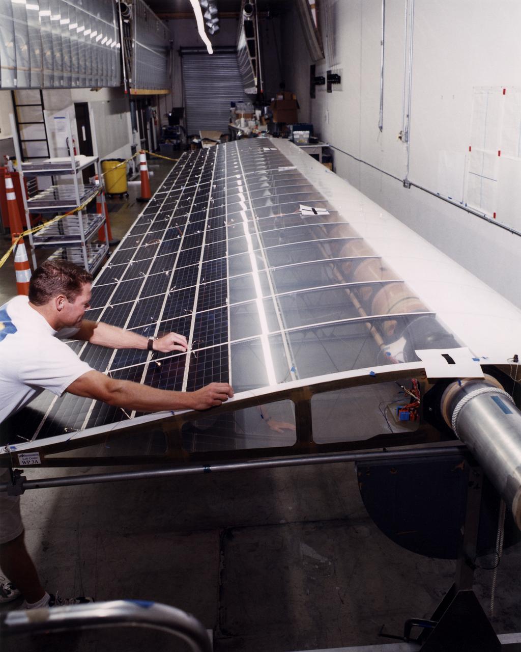
Technician Marshall MacCready carefully lays a panel of solar cells into place on a wing section of the Helios Prototype flying wing at AeroVironment's Design Development Center in Simi Valley, California. The bi-facial cells, manufactured by SunPower, Inc., of Sunnyvale, California, are among 64,000 solar cells which have been installed on the solar-powered aircraft to provide electricity to its 14 motors and operating systems.
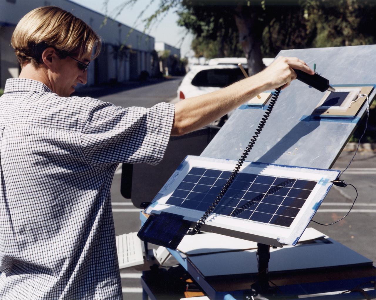
A technician at AeroVironment's Design Development Center in Simi Valley, California, checks a panel of silicon solar cells for conductivity and voltage. The bi-facial cells, fabricated by SunPower, Inc., of Sunnyvale, California, are among 64,000 solar cells which have been installed on the Helios Prototype solar-powered aircraft to provide power to its 14 electric motors and operating systems.
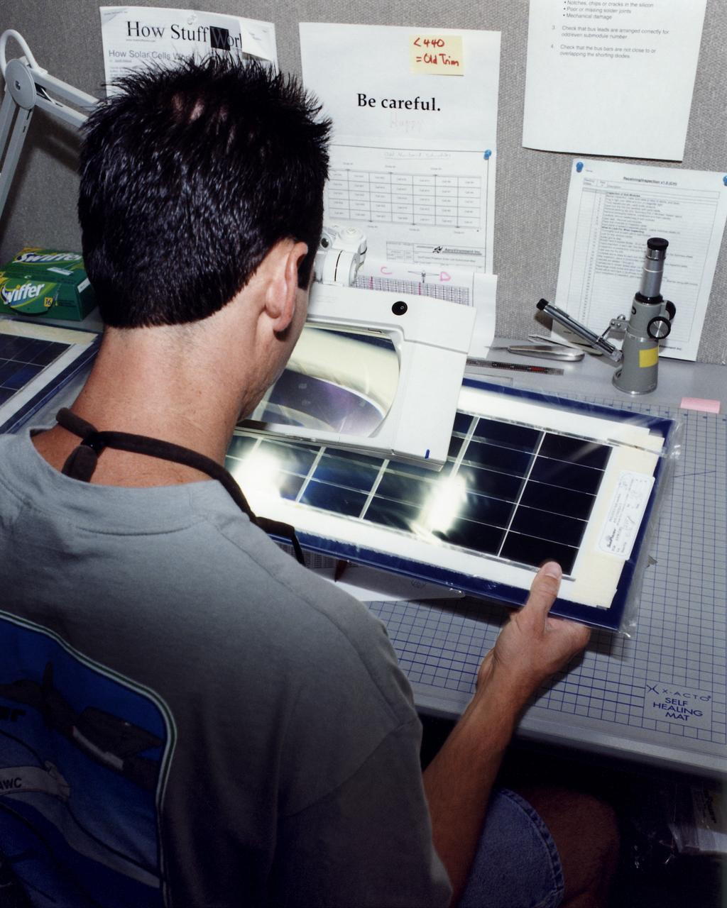
An engineer at AeroVironment's Design Development Center in Simi Valley, California, closely inspects a set of silicon solar cells for potential defects. The cells, fabricated by SunPower, Inc., of Sunnyvale, California, are among 64,000 solar cells which have been installed on the Helios Prototype solar-powered aircraft to provide power to its 14 electric motors and operating systems.
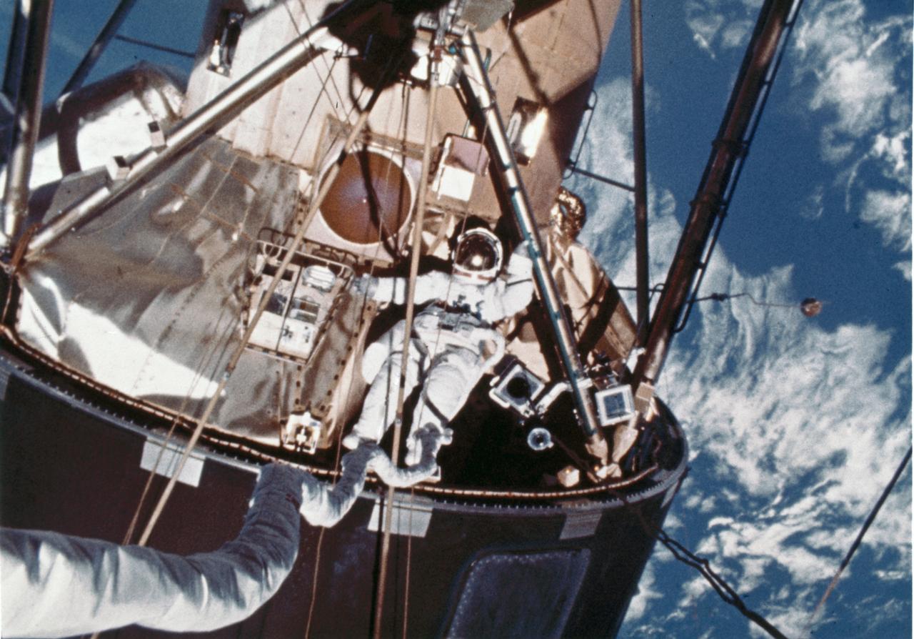
In this photograph, a skylab-4 astronaut performs Extra Vehicular Activities (EVA) outside of the lab. The third crew (Skylab-4) spent 84 days in the orbiting laboratory. The solar observatory was designed for full exposure to the Sun throughout most of the Skylab mission. Solar energy was transformed into electrical power for operation of all spacecraft systems. The proper operation of these solar arrays was vital to the mission.
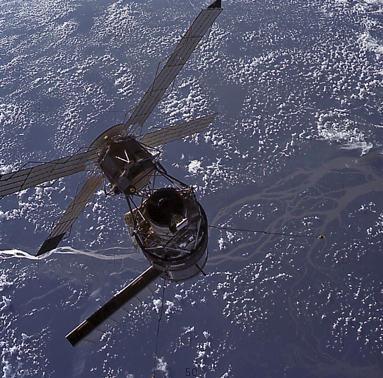
This striking image of Skylab was photographed by Astronaut Jack Lousma (Skylab-3), as the second crew reached the orbiting laboratory over the delta of the mighty Amazon River. Skylab's solar arrays were exposed directly to the Sun's rays. Solar energy was transformed into electrical power for operation of all spacecraft systems. The proper operation of these solar arrays was vital to the mission.
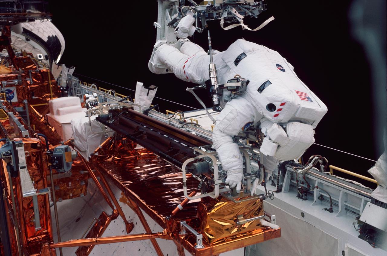
STS109-326-008 (5 March 2002) --- Astronaut Michael J. Massimino, mission specialist, works at the stowage area for the Hubble Space Telescope's port side solar array. Astronauts Massimino and James H. Newman removed the old port solar array and stowed it in Columbia’s payload bay for a return to Earth. They then went on to install a third-generation solar array and its associated electrical components. Two crew mates had accomplished the same feat with the starboard array on the previous day.

This photograph was taken as the third crew (Skylab-4) departed the space station. The solar observatory was designed for full exposure to the Sun throughout most of the Skylab mission. Solar energy was transformed into electrical power for operation of all spacecraft systems. The proper operation of these solar arrays was vital to the mission. This Skylab in orbit view was taken by the Skylab-4 crew.
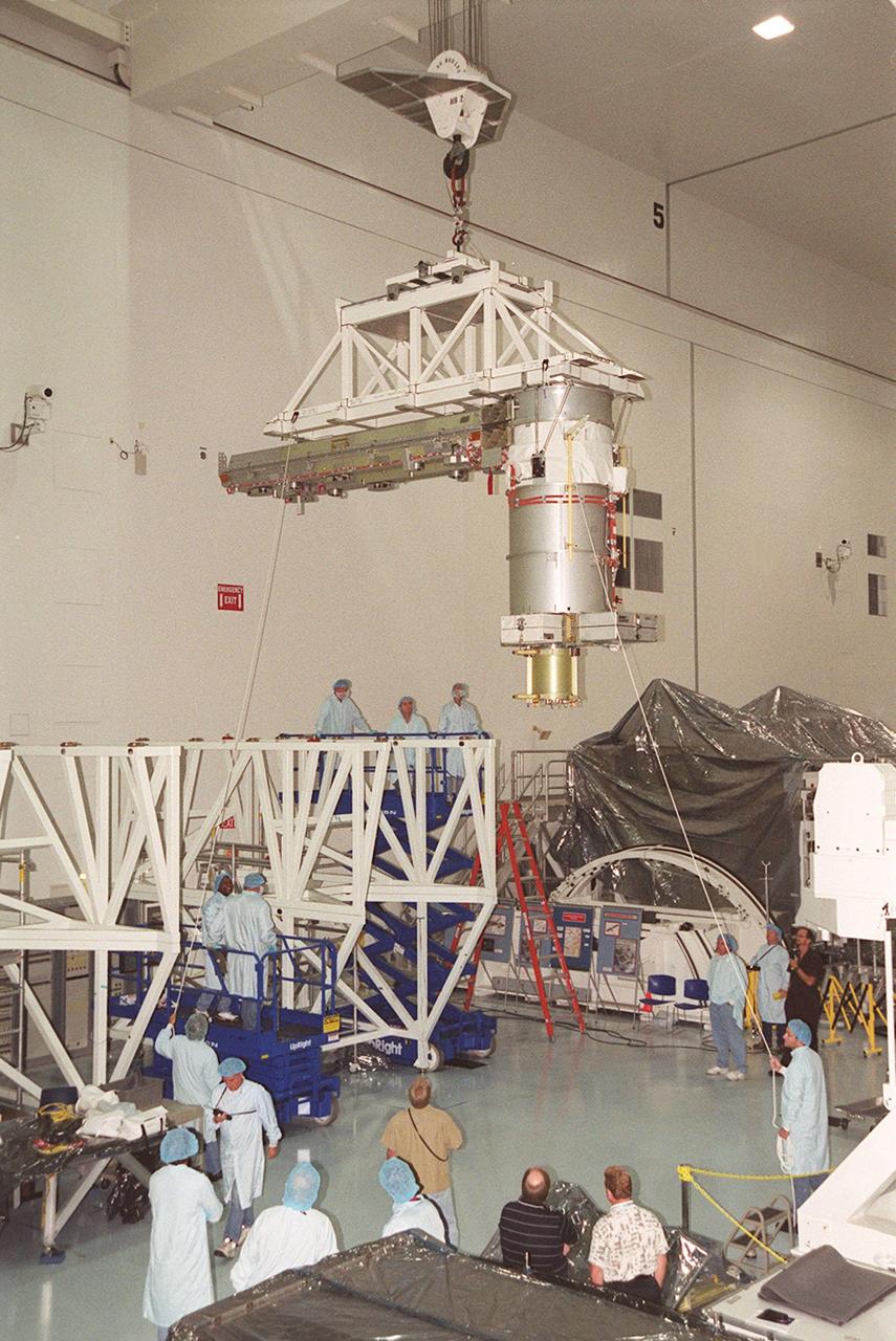
KENNEDY SPACE CENTER, FLA. -- In the Space Station Processing Facility, the P6 integrated truss segment is placed in the payload transport canister while workers watch its progress. After being secured in the canister, the truss will be transported to Launch Pad 39B and the payload changeout room. Then it will be moved into Space Shuttle Endeavour’s payload bay for mission STS-97. The P6 comprises Solar Array Wing-3 and the Integrated Electronic Assembly, to be installed on the Space Station. The Station’s electrical power system will use eight photovoltaic solar arrays, each 112 feet long by 39 feet wide, to convert sunlight to electricity. The solar arrays are mounted on a “blanket” that can be folded like an accordion for delivery. Once in orbit, astronauts will deploy the blankets to their full size. Gimbals will be used to rotate the arrays so that they will face the Sun to provide maximum power to the Space Station. The STS-97 launch is scheduled Nov. 30 at 10:06 p.m. EST
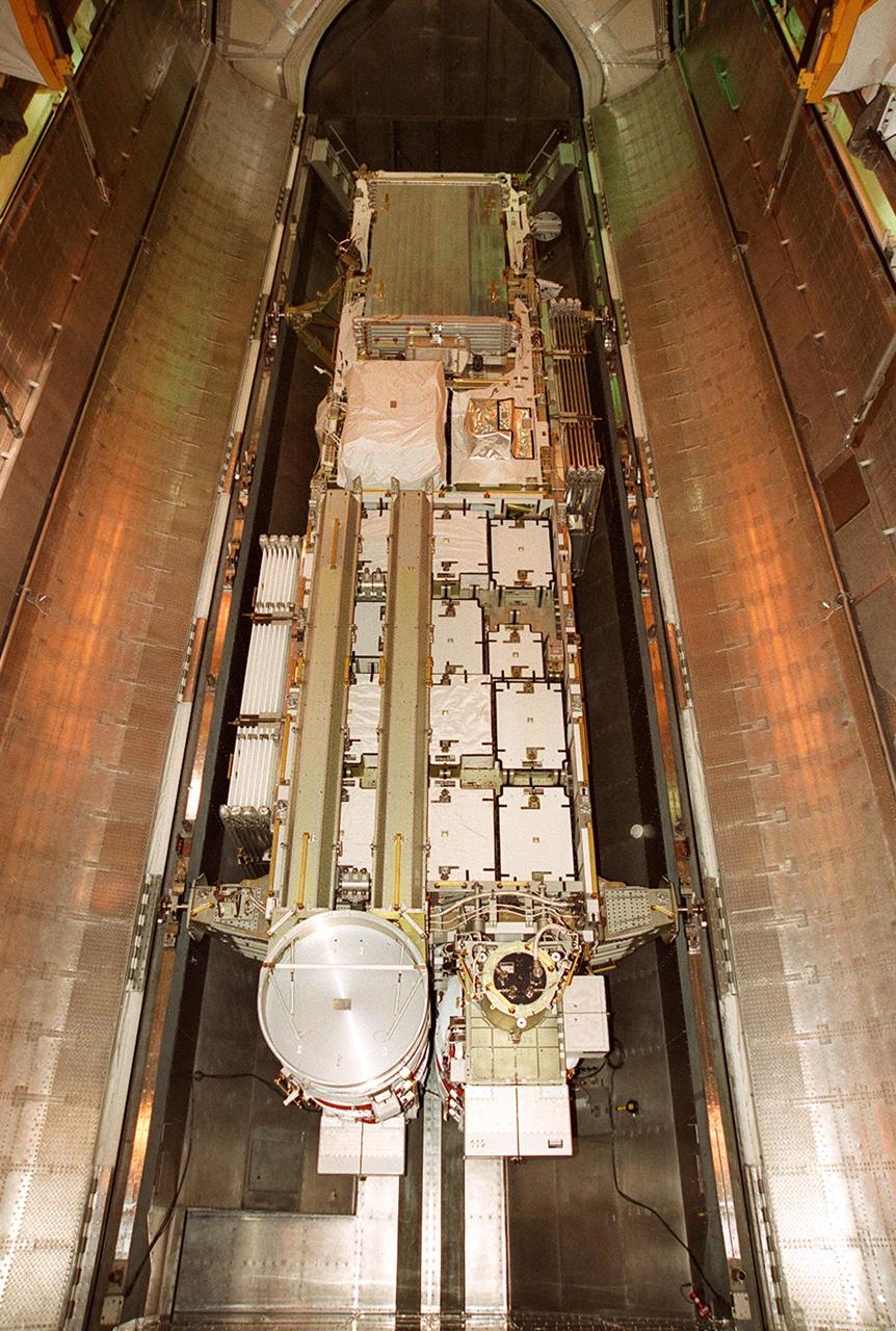
The doors of the payload transport canister are open wide in the payload changeout room on Launch Pad 39B. Revealed is the P6 integrated truss segment, which will fly on mission STS-97. The P6 comprises Solar Array Wing-3 and the Integrated Electronic Assembly, to be installed on the International Space Station. The Station’s electrical power system will use eight photovoltaic solar arrays, each 112 feet long by 39 feet wide, to convert sunlight to electricity. The solar arrays are mounted on a “blanket” that can be folded like an accordion for delivery. Once in orbit, astronauts will deploy the blankets to their full size. Gimbals will be used to rotate the arrays so that they will face the Sun to provide maximum power to the Space Station. Launch of STS-97 is scheduled for Nov. 30 at 10:06 p.m. EST
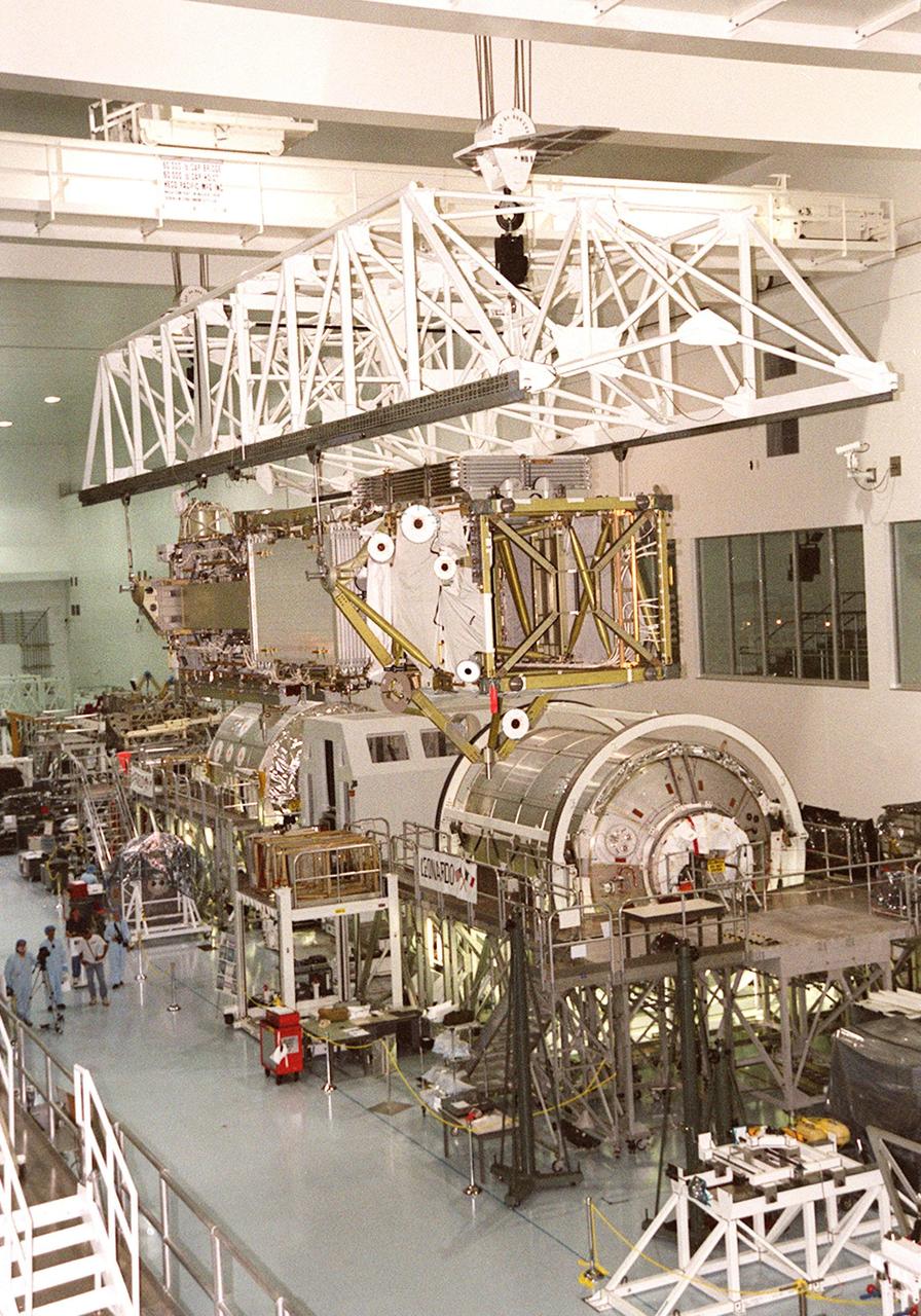
As it travels across the Space Station Processing Facility, the P6 integrated truss segment passes over the two Italian-built Multi-Purpose Logistics Modules, Leonardo (right) and Raffaello (behind Leonardo). The P6 is being moved to a payload transport canister for transfer to Launch Pad 39B. There it will be placed in Endeavour’s payload bay for launch on mission STS-97. The P6 comprises Solar Array Wing-3 and the Integrated Electronic Assembly, to be installed on the Space Station. The Station’s electrical power system will use eight photovoltaic solar arrays, each 112 feet long by 39 feet wide, to convert sunlight to electricity. The solar arrays are mounted on a “blanket” that can be folded like an accordion for delivery. Once in orbit, astronauts will deploy the blankets to their full size. Gimbals will be used to rotate the arrays so that they will face the Sun to provide maximum power to the Space Station. Launch is scheduled Nov. 30 at 10:06 p.m. EST
In the Space Station Processing Facility, an overhead crane moves the P6 integrated truss segment to a payload transport canister for transfer to Launch Pad 39B. There it will be placed in Endeavour’s payload bay for launch on mission STS-97. The P6 comprises Solar Array Wing-3 and the Integrated Electronic Assembly, to be installed on the International Space Station. The Station’s electrical power system will use eight photovoltaic solar arrays, each 112 feet long by 39 feet wide, to convert sunlight to electricity. The solar arrays are mounted on a “blanket” that can be folded like an accordion for delivery. Once in orbit, astronauts will deploy the blankets to their full size. Gimbals will be used to rotate the arrays so that they will face the Sun to provide maximum power to the Space Station. Launch is scheduled Nov. 30 at 10:06 p.m. EST
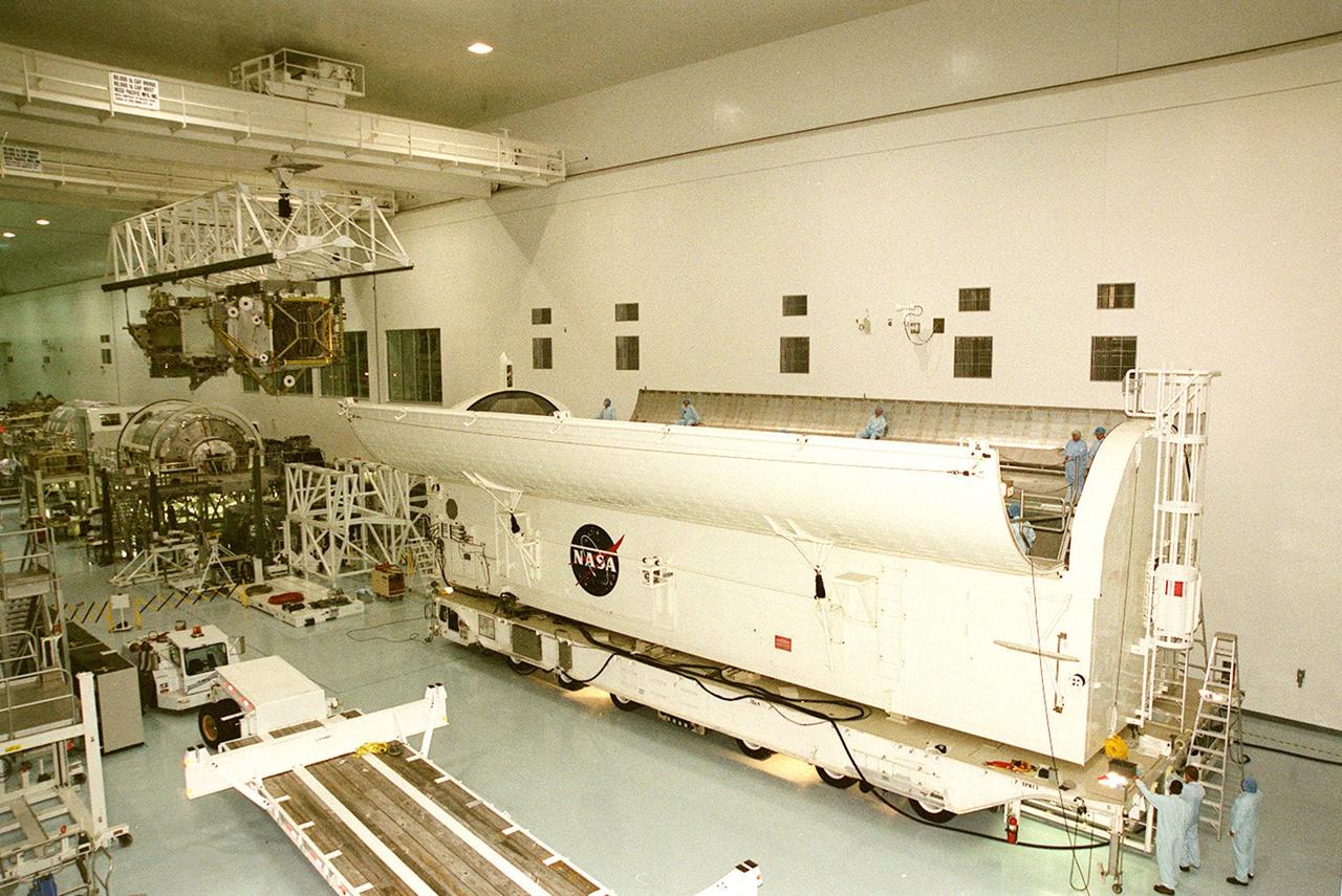
KENNEDY SPACE CENTER, FLA. -- The payload transport canister (right) and workers wait for the arrival of the P6 integrated truss segment (left) carried by the overhead crane. After being placed in the canister, the truss will be transported to Launch Pad 39B and the payload changeout room. Then it will be moved into Space Shuttle Endeavour’s payload bay for mission STS-97. The P6 comprises Solar Array Wing-3 and the Integrated Electronic Assembly, to be installed on the Space Station. The Station’s electrical power system will use eight photovoltaic solar arrays, each 112 feet long by 39 feet wide, to convert sunlight to electricity. The solar arrays are mounted on a “blanket” that can be folded like an accordion for delivery. Once in orbit, astronauts will deploy the blankets to their full size. Gimbals will be used to rotate the arrays so that they will face the Sun to provide maximum power to the Space Station. The STS-97 launch is scheduled Nov. 30 at 10:06 p.m. EST
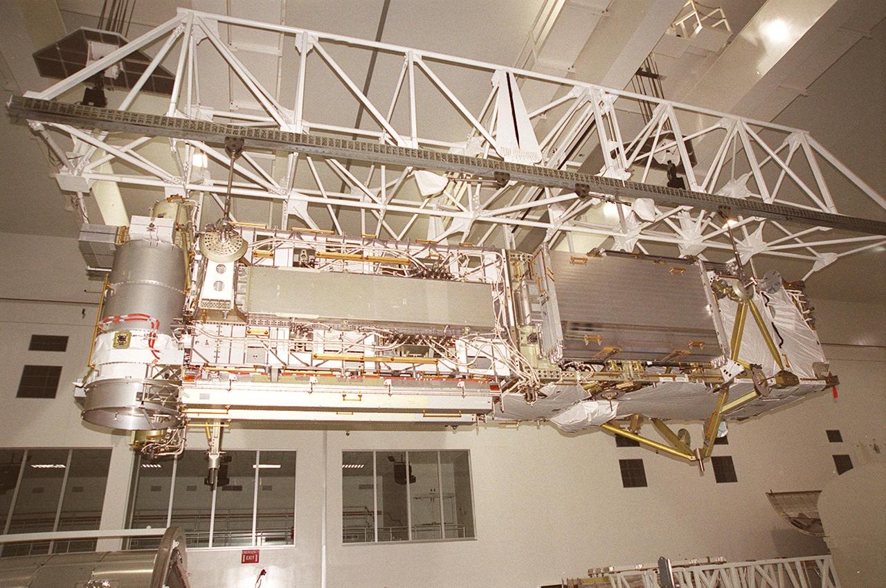
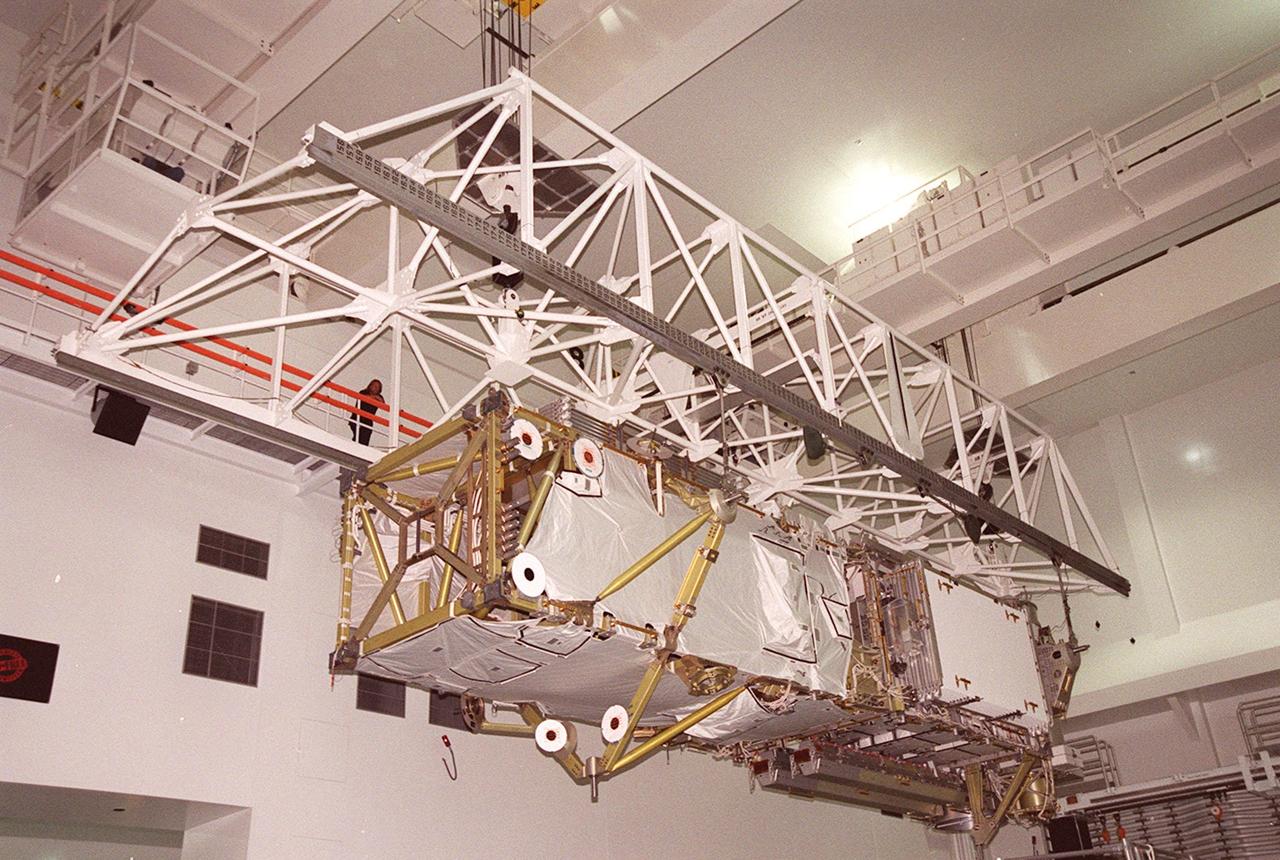
The P6 integrated truss segment hangs suspended from an overhead crane that is moving it the length of the Space Station Processing Facility toward a payload transport canister for transfer to Launch Pad 39B. At the pad, the Space Station element will be placed in Endeavour’s payload bay for launch on mission STS-97. The P6 comprises Solar Array Wing-3 and the Integrated Electronic Assembly, to be installed on the Space Station. The Station’s electrical power system will use eight photovoltaic solar arrays, each 112 feet long by 39 feet wide, to convert sunlight to electricity. The solar arrays are mounted on a “blanket” that can be folded like an accordion for delivery. Once in orbit, astronauts will deploy the blankets to their full size. Gimbals will be used to rotate the arrays so that they will face the Sun to provide maximum power to the Space Station. The STS-97 launch is scheduled Nov. 30 at 10:06 p.m. EST
In the Space Station Processing Facility, the P6 integrated truss segment travels across the building to a payload transport canister for transfer to Launch Pad 39B. There it will be placed in Endeavour’s payload bay for launch on mission STS-97. At left is the airlock module, another component of the International Space Station. The P6 comprises Solar Array Wing-3 and the Integrated Electronic Assembly, to be installed on the Space Station. The Station’s electrical power system will use eight photovoltaic solar arrays, each 112 feet long by 39 feet wide, to convert sunlight to electricity. The solar arrays are mounted on a “blanket” that can be folded like an accordion for delivery. Once in orbit, astronauts will deploy the blankets to their full size. Gimbals will be used to rotate the arrays so that they will face the Sun to provide maximum power to the Space Station. Launch is scheduled Nov. 30 at 10:06 p.m. EST