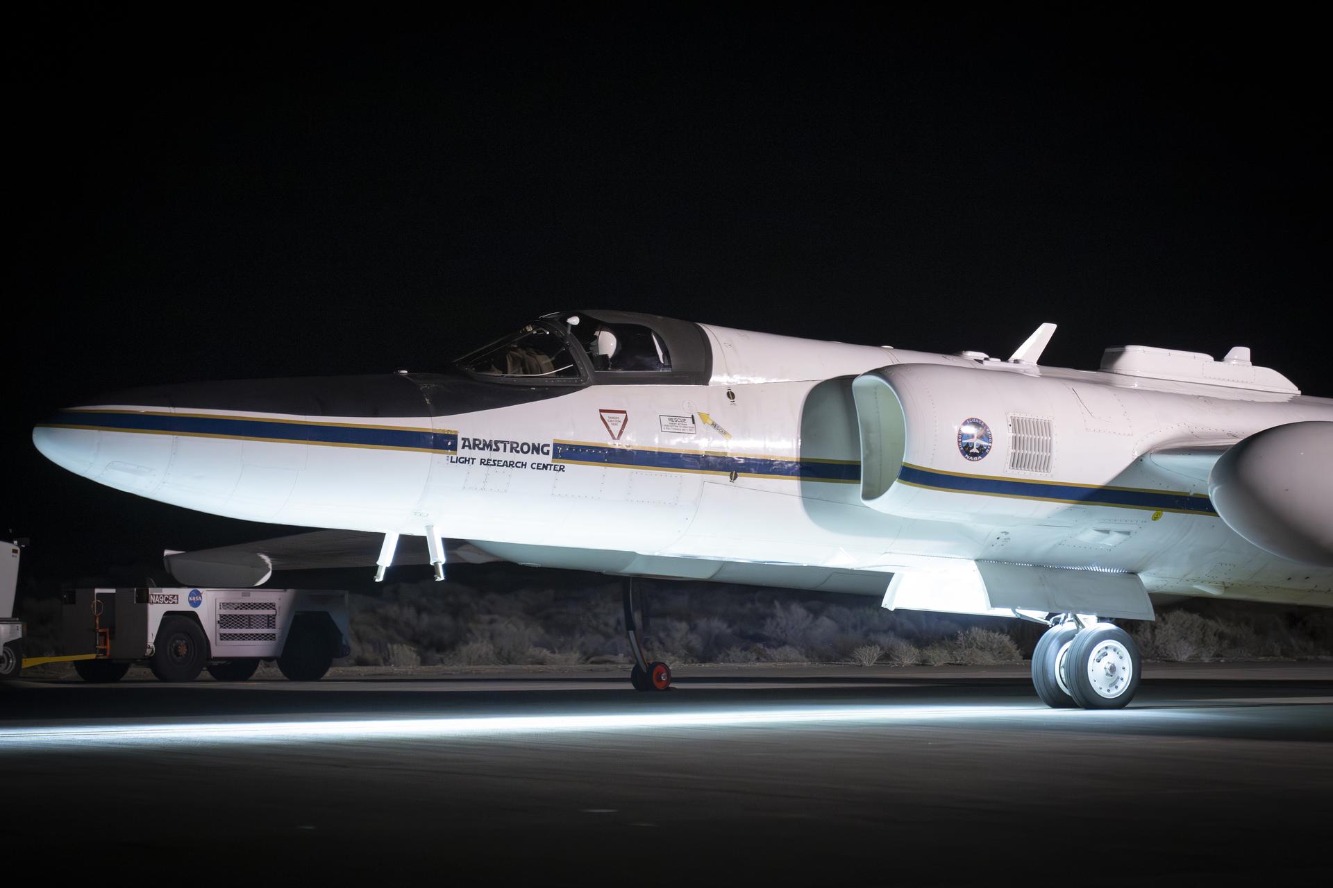
NASA’s ER-2 high-altitude aircraft prepares for a night flight with the Airborne Lunar Spectral Irradiance (air-LUSI) instrument on Monday, Feb. 2, 2026. The instrument measures Moonlight to improve accuracy of space-based sensors that forecast the weather, monitor agriculture, and study Earth’s ecosystem.
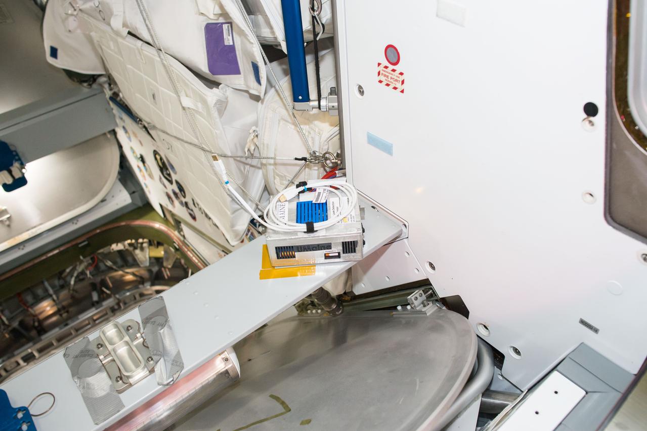
iss050e035315 (1/26/2017) --- A view of the Wireless Leak Detector Ultrasonic Sensor aboard the International Space Station (ISS). The Joint Leak Detection and Localization Based on Fast Bayesian Inference from Network of Ultrasonic Sensor Arrays in Microgravity Environment (Wireless Leak Detection) investigation compares signals received at various ultrasonic sensors to reveal the location of air leaks, which can then be repaired.
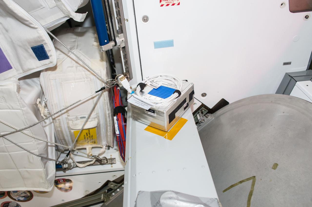
iss050e035313 (1/26/2017) --- A view of the Wireless Leak Detector Ultrasonic Sensor aboard the International Space Station (ISS). The Joint Leak Detection and Localization Based on Fast Bayesian Inference from Network of Ultrasonic Sensor Arrays in Microgravity Environment (Wireless Leak Detection) investigation compares signals received at various ultrasonic sensors to reveal the location of air leaks, which can then be repaired.
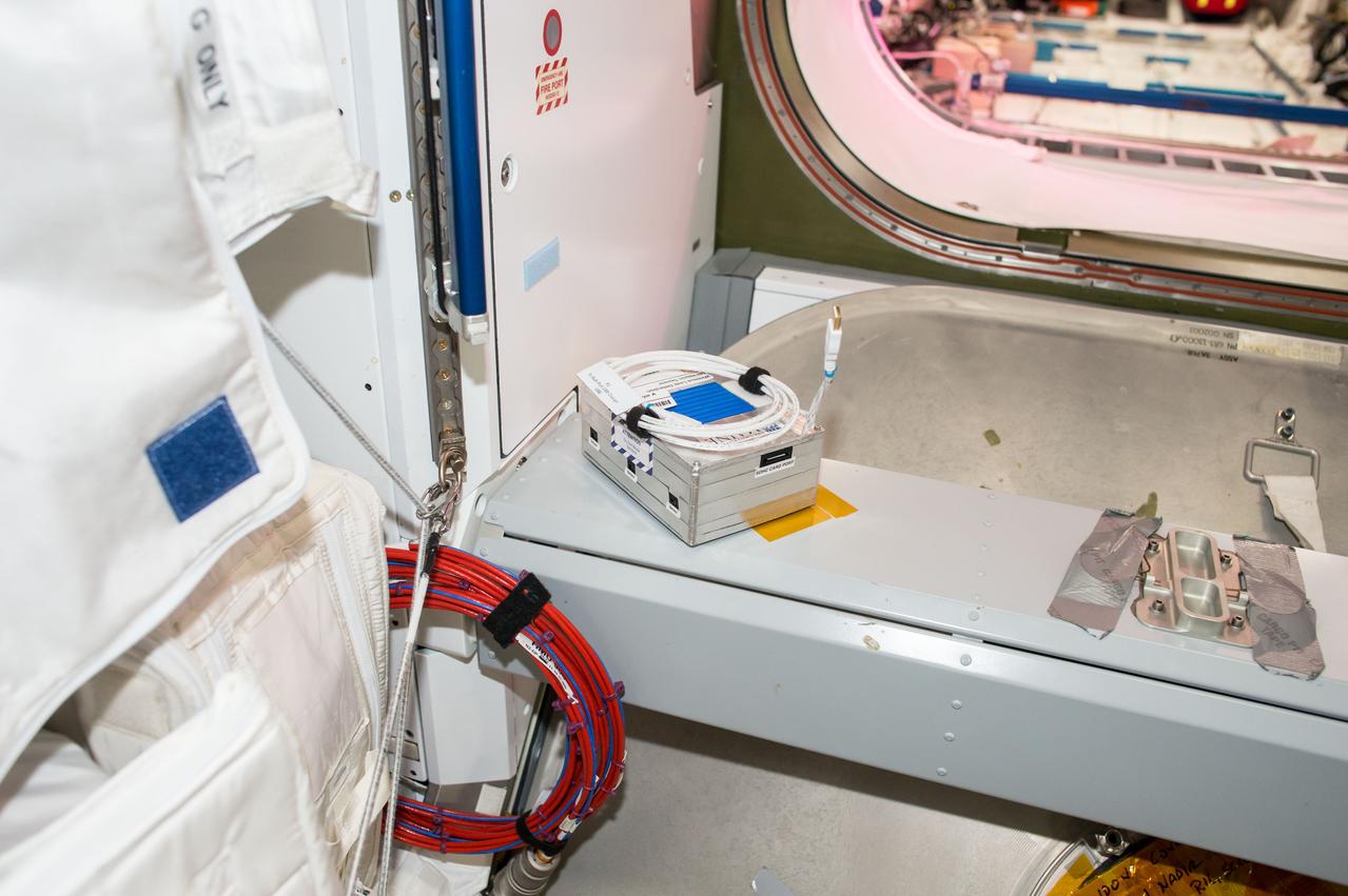
iss050e035314 (1/26/2017) --- A view of the Wireless Leak Detector Ultrasonic Sensor aboard the International Space Station (ISS). The Joint Leak Detection and Localization Based on Fast Bayesian Inference from Network of Ultrasonic Sensor Arrays in Microgravity Environment (Wireless Leak Detection) investigation compares signals received at various ultrasonic sensors to reveal the location of air leaks, which can then be repaired.
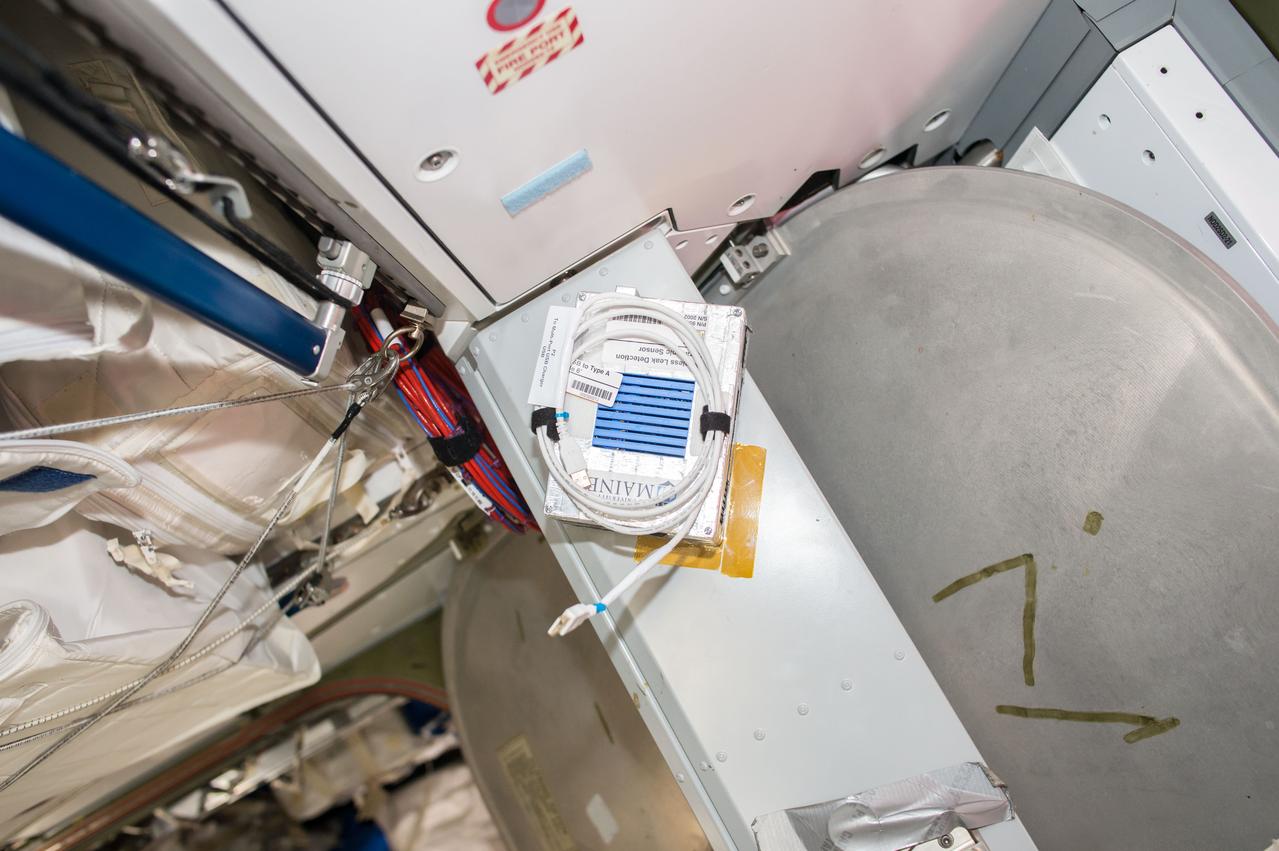
iss050e035316 (1/26/2017) --- A view of the Wireless Leak Detector Ultrasonic Sensor aboard the International Space Station (ISS). The Joint Leak Detection and Localization Based on Fast Bayesian Inference from Network of Ultrasonic Sensor Arrays in Microgravity Environment (Wireless Leak Detection) investigation compares signals received at various ultrasonic sensors to reveal the location of air leaks, which can then be repaired.
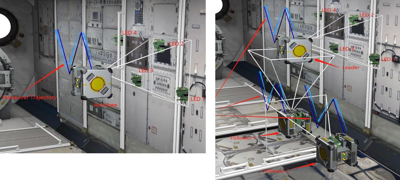
jsc2025e032821 (3/20/2025) --- Smartphone Video Guidance Sensor (SVGS) proximity maneuvers on the International Space Station. Left: navigation based on color-coded targets, Right: formation flight. Image courtesy of Hector Gutierrez.
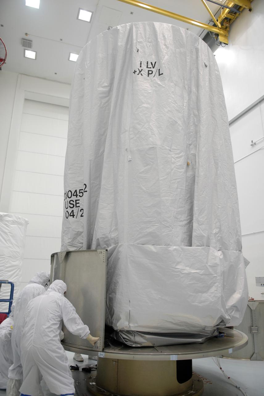
CAPE CANAVERAL, Fla. – At the Astrotech payload processing facility in Titusville, Fla., workers place the first segments of the transportation canister around the base of the Space Tracking and Surveillance System – Demonstrators, or STSS Demo, spacecraft. The STSS Demo is a space-based sensor component of a layered Ballistic Missile Defense System designed for the overall mission of detecting, tracking and discriminating ballistic missiles. STSS is capable of tracking objects after boost phase and provides trajectory information to other sensors. It will be launched by NASA for the Missile Defense Agency between 8 and 8:58 a.m. EDT Sept. 18. Approved for Public Release 09-MDA-04886 (10 SEPT 09) Photo credit: NASA/Kim Shiflett
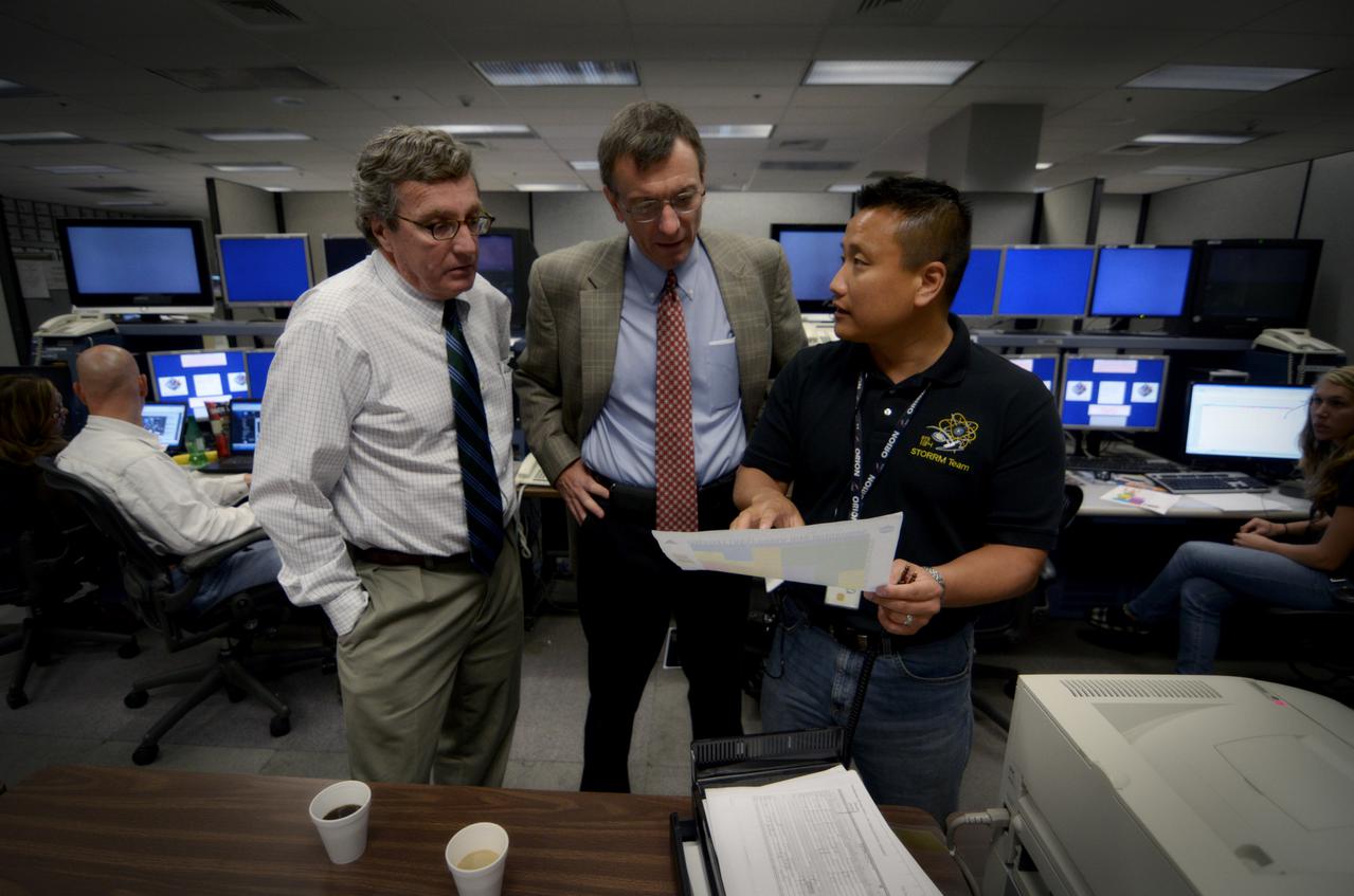
Teams conduct powerup and docking operations for the Sensor Test for Orion Relative Navigation Risk Mitigation (STORRM) in a payload support room at Johnson Space Center’s Mission Control Center in Houston on May 18, 2011. STORRM was successfully demonstrated on Space Shuttle Endeavour’s STS-134 mission to the International Space Station. The goal of STORRM was to validate a new relative navigation sensor based on advanced laser and detector technology that will make docking and undocking spacecraft easier and safer. It also tested the hardware in the same environment that the sensors would experience on the first Orion rendezvous to another vehicle.
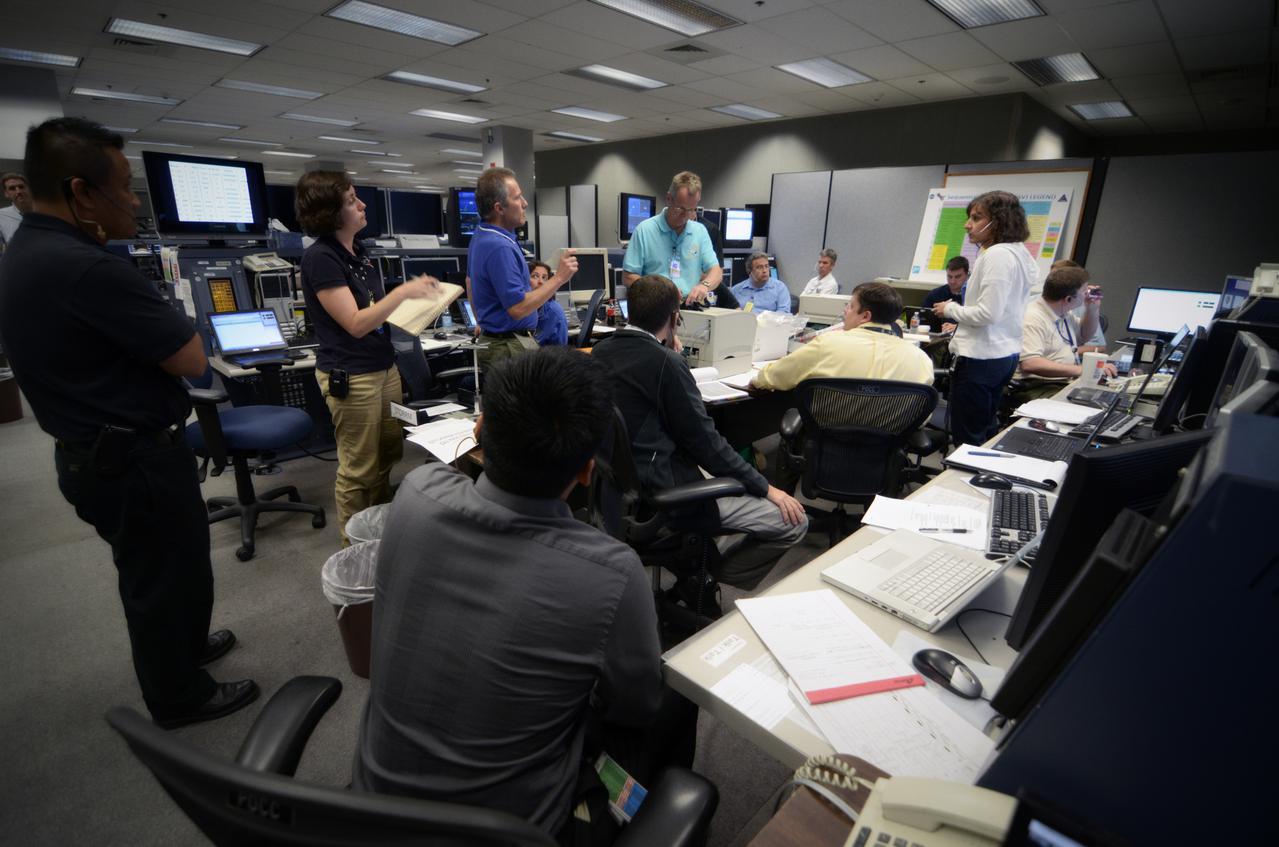
Teams conduct powerup and docking operations for the Sensor Test for Orion Relative Navigation Risk Mitigation (STORRM) in a payload support room at Johnson Space Center’s Mission Control Center in Houston on May 17, 2011. STORRM was successfully demonstrated on Space Shuttle Endeavour’s STS-134 mission to the International Space Station. The goal of STORRM was to validate a new relative navigation sensor based on advanced laser and detector technology that will make docking and undocking spacecraft easier and safer. It also tested the hardware in the same environment that the sensors would experience on the first Orion rendezvous to another vehicle.

Teams conduct powerup and docking operations for the Sensor Test for Orion Relative Navigation Risk Mitigation (STORRM) in a payload support room at Johnson Space Center’s Mission Control Center in Houston on May 18, 2011. STORRM was successfully demonstrated on Space Shuttle Endeavour’s STS-134 mission to the International Space Station. The goal of STORRM was to validate a new relative navigation sensor based on advanced laser and detector technology that will make docking and undocking spacecraft easier and safer. It also tested the hardware in the same environment that the sensors would experience on the first Orion rendezvous to another vehicle.
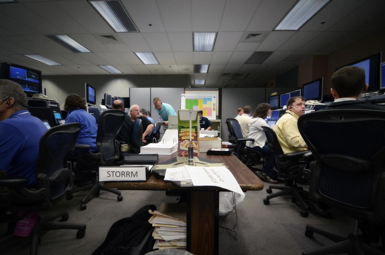
Teams conduct powerup and docking operations for the Sensor Test for Orion Relative Navigation Risk Mitigation (STORRM) in a payload support room at Johnson Space Center’s Mission Control Center in Houston on May 17, 2011. STORRM was successfully demonstrated on Space Shuttle Endeavour’s STS-134 mission to the International Space Station. The goal of STORRM was to validate a new relative navigation sensor based on advanced laser and detector technology that will make docking and undocking spacecraft easier and safer. It also tested the hardware in the same environment that the sensors would experience on the first Orion rendezvous to another vehicle.

Teams conduct powerup and docking operations for the Sensor Test for Orion Relative Navigation Risk Mitigation (STORRM) in a payload support room at Johnson Space Center’s Mission Control Center in Houston on May 18, 2011. STORMM was successfully demonstrated on Space Shuttle Endeavour’s STS-134 mission to the International Space Station..The goal of STORRM was to validate a new relative navigation sensor based on advanced laser and detector technology that will make docking and undocking spacecraft easier and safer. It also tested the hardware in the same environment that the sensors would experience on the first Orion rendezvous to another vehicle. Part of Batch image transfer from Flickr.
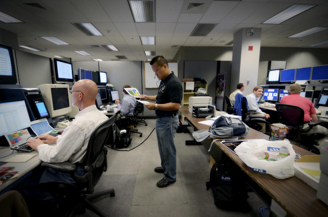
Teams conduct powerup and docking operations for the Sensor Test for Orion Relative Navigation Risk Mitigation (STORRM) in a payload support room at Johnson Space Center’s Mission Control Center in Houston on May 18, 2011. STORRM was successfully demonstrated on Space Shuttle Endeavour’s STS-134 mission to the International Space Station. The goal of STORRM was to validate a new relative navigation sensor based on advanced laser and detector technology that will make docking and undocking spacecraft easier and safer. It also tested the hardware in the same environment that the sensors would experience on the first Orion rendezvous to another vehicle.
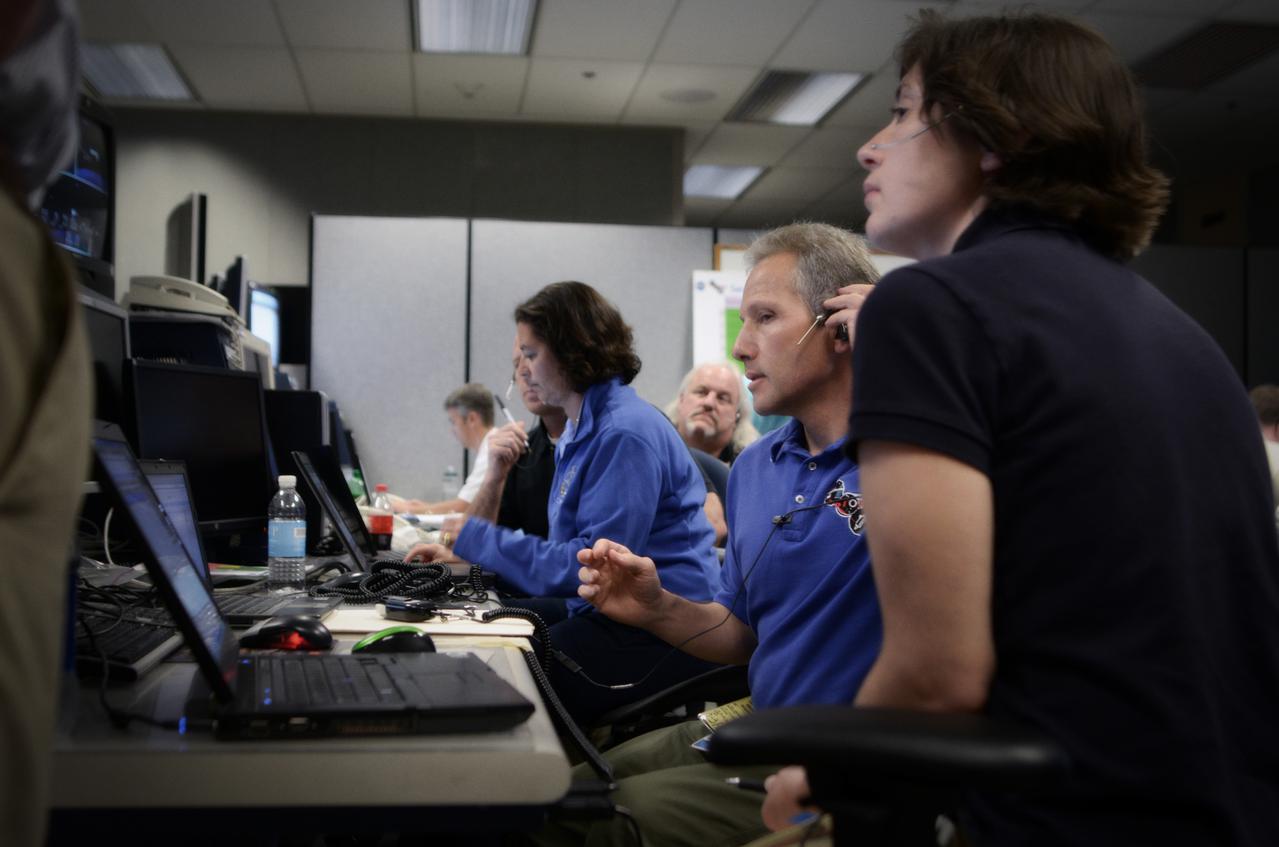
Teams conduct powerup and docking operations for the Sensor Test for Orion Relative Navigation Risk Mitigation (STORRM) in a payload support room at Johnson Space Center’s Mission Control Center in Houston on May 17, 2011. STORRM was successfully demonstrated on Space Shuttle Endeavour’s STS-134 mission to the International Space Station. The goal of STORRM was to validate a new relative navigation sensor based on advanced laser and detector technology that will make docking and undocking spacecraft easier and safer. It also tested the hardware in the same environment that the sensors would experience on the first Orion rendezvous to another vehicle.
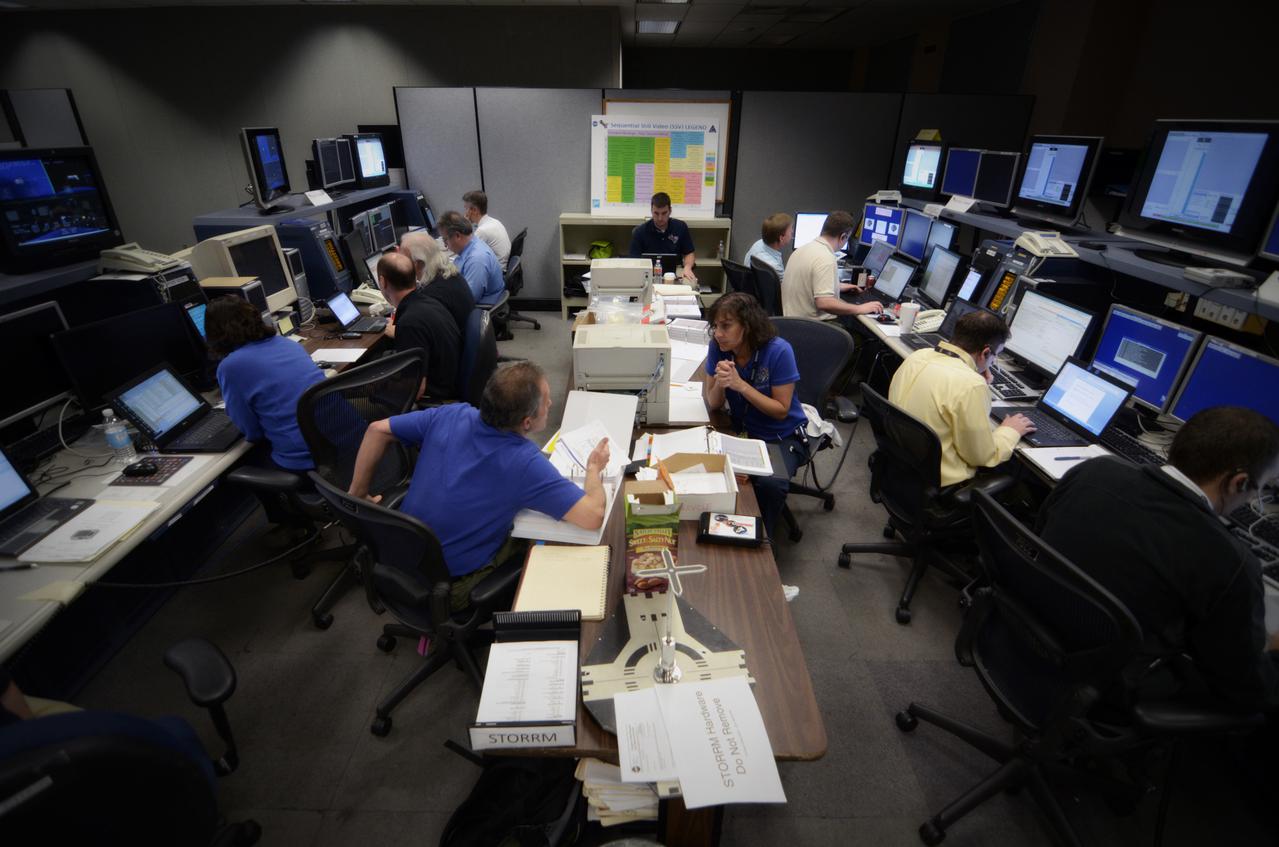
Teams conduct powerup and docking operations for the Sensor Test for Orion Relative Navigation Risk Mitigation (STORRM) in a payload support room at Johnson Space Center’s Mission Control Center in Houston on May 17, 2011. STORRM was successfully demonstrated on Space Shuttle Endeavour’s STS-134 mission to the International Space Station. The goal of STORRM was to validate a new relative navigation sensor based on advanced laser and detector technology that will make docking and undocking spacecraft easier and safer. It also tested the hardware in the same environment that the sensors would experience on the first Orion rendezvous to another vehicle.
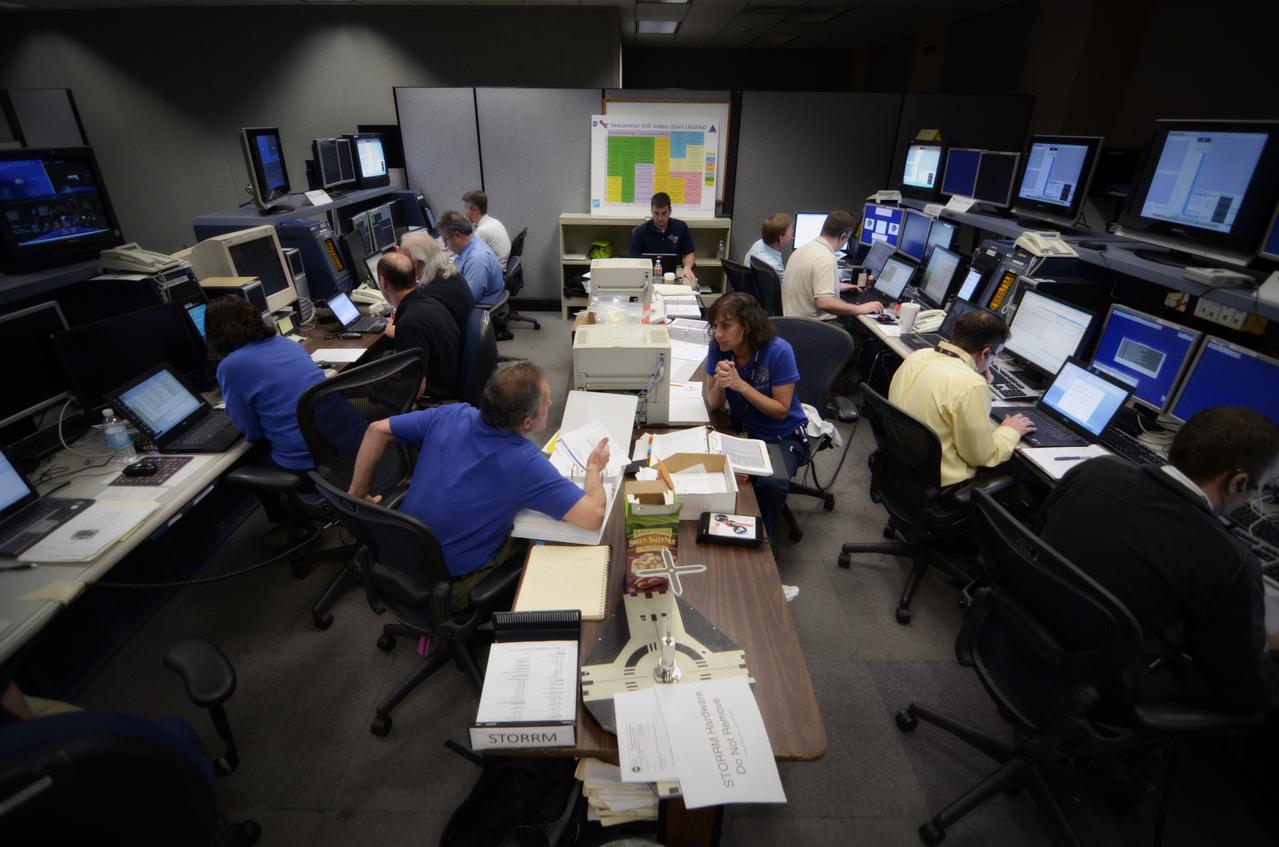
Teams conduct powerup and docking operations for the Sensor Test for Orion Relative Navigation Risk Mitigation (STORRM) in a payload support room at Johnson Space Center’s Mission Control Center in Houston on May 18, 2011. STORMM was successfully demonstrated on Space Shuttle Endeavour’s STS-134 mission to the International Space Station..The goal of STORRM was to validate a new relative navigation sensor based on advanced laser and detector technology that will make docking and undocking spacecraft easier and safer. It also tested the hardware in the same environment that the sensors would experience on the first Orion rendezvous to another vehicle. Part of Batch image transfer from Flickr.
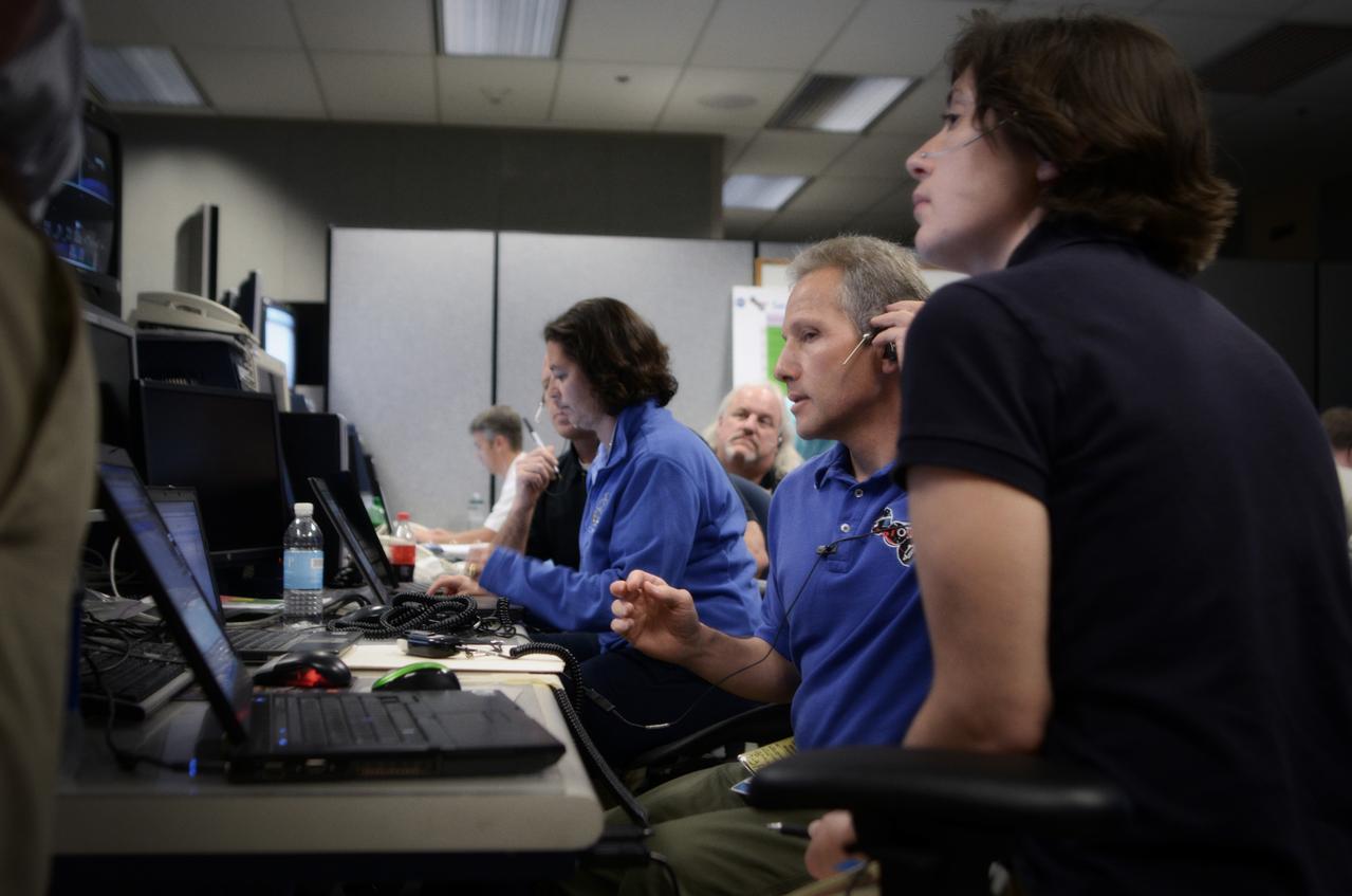
Teams conduct powerup and docking operations for the Sensor Test for Orion Relative Navigation Risk Mitigation (STORRM) in a payload support room at Johnson Space Center’s Mission Control Center in Houston on May 18, 2011. STORMM was successfully demonstrated on Space Shuttle Endeavour’s STS-134 mission to the International Space Station..The goal of STORRM was to validate a new relative navigation sensor based on advanced laser and detector technology that will make docking and undocking spacecraft easier and safer. It also tested the hardware in the same environment that the sensors would experience on the first Orion rendezvous to another vehicle. Part of Batch image transfer from Flickr.
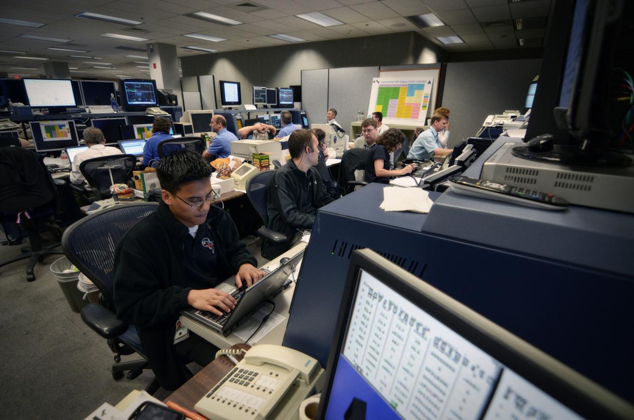
Teams conduct powerup and docking operations for the Sensor Test for Orion Relative Navigation Risk Mitigation (STORRM) in a payload support room at Johnson Space Center’s Mission Control Center in Houston on May 18, 2011. STORMM was successfully demonstrated on Space Shuttle Endeavour’s STS-134 mission to the International Space Station..The goal of STORRM was to validate a new relative navigation sensor based on advanced laser and detector technology that will make docking and undocking spacecraft easier and safer. It also tested the hardware in the same environment that the sensors would experience on the first Orion rendezvous to another vehicle. Part of Batch image transfer from Flickr.
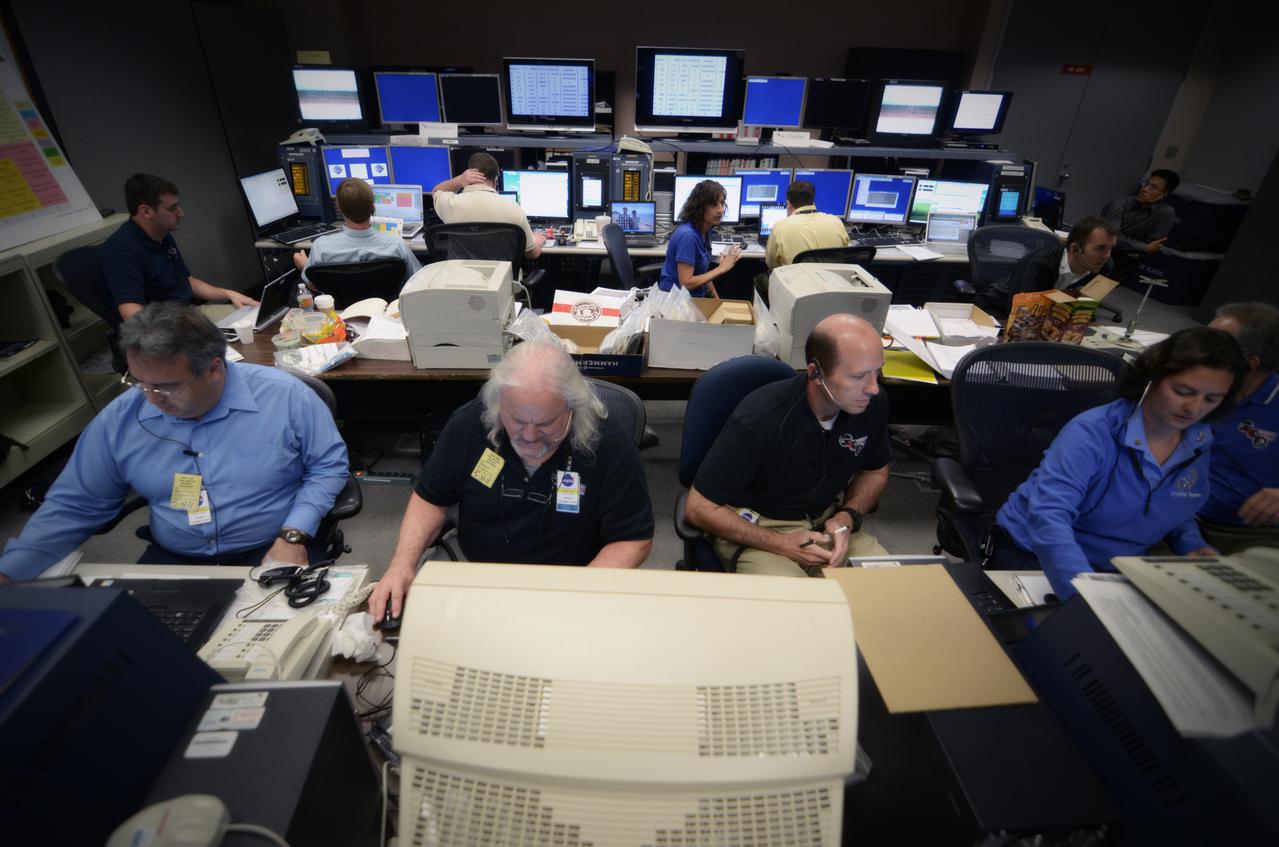
Teams conduct powerup and docking operations for the Sensor Test for Orion Relative Navigation Risk Mitigation (STORRM) in a payload support room at Johnson Space Center’s Mission Control Center in Houston on May 17, 2011. STORRM was successfully demonstrated on Space Shuttle Endeavour’s STS-134 mission to the International Space Station. The goal of STORRM was to validate a new relative navigation sensor based on advanced laser and detector technology that will make docking and undocking spacecraft easier and safer. It also tested the hardware in the same environment that the sensors would experience on the first Orion rendezvous to another vehicle.
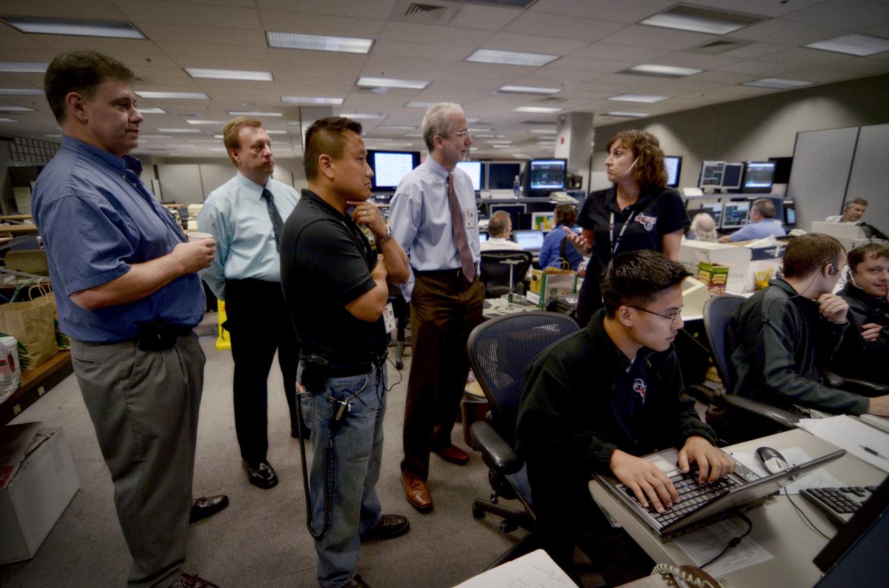
Teams conduct powerup and docking operations for the Sensor Test for Orion Relative Navigation Risk Mitigation (STORRM) in a payload support room at Johnson Space Center’s Mission Control Center in Houston on May 18, 2011. STORRM was successfully demonstrated on Space Shuttle Endeavour’s STS-134 mission to the International Space Station. The goal of STORRM was to validate a new relative navigation sensor based on advanced laser and detector technology that will make docking and undocking spacecraft easier and safer. It also tested the hardware in the same environment that the sensors would experience on the first Orion rendezvous to another vehicle.
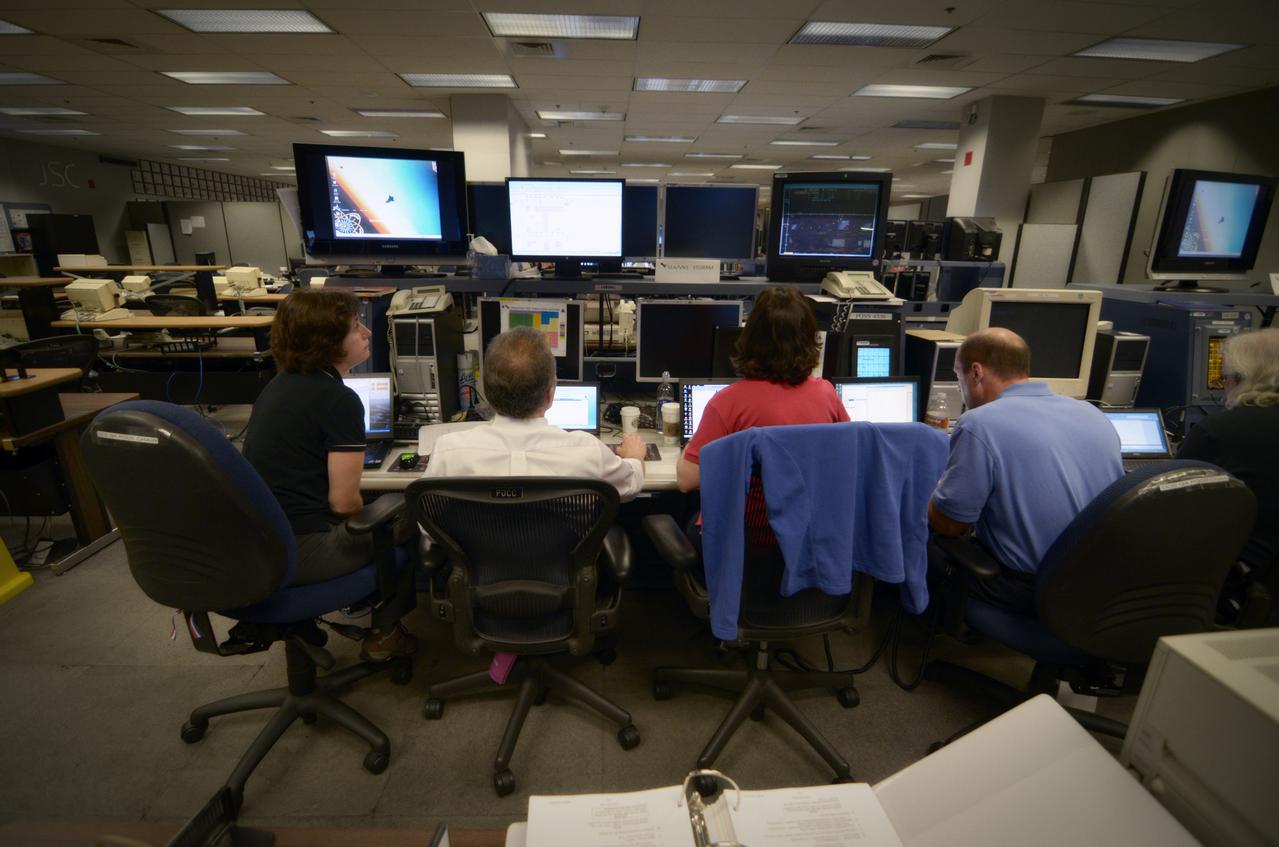
Teams conduct powerup and docking operations for the Sensor Test for Orion Relative Navigation Risk Mitigation (STORRM) in a payload support room at Johnson Space Center’s Mission Control Center in Houston on May 18, 2011. STORMM was successfully demonstrated on Space Shuttle Endeavour’s STS-134 mission to the International Space Station..The goal of STORRM was to validate a new relative navigation sensor based on advanced laser and detector technology that will make docking and undocking spacecraft easier and safer. It also tested the hardware in the same environment that the sensors would experience on the first Orion rendezvous to another vehicle. Part of Batch image transfer from Flickr.
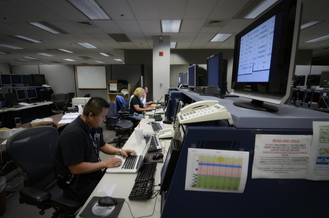
Teams conduct powerup and docking operations for the Sensor Test for Orion Relative Navigation Risk Mitigation (STORRM) in a payload support room at Johnson Space Center’s Mission Control Center in Houston on May 18, 2011. STORMM was successfully demonstrated on Space Shuttle Endeavour’s STS-134 mission to the International Space Station..The goal of STORRM was to validate a new relative navigation sensor based on advanced laser and detector technology that will make docking and undocking spacecraft easier and safer. It also tested the hardware in the same environment that the sensors would experience on the first Orion rendezvous to another vehicle. Part of Batch image transfer from Flickr.
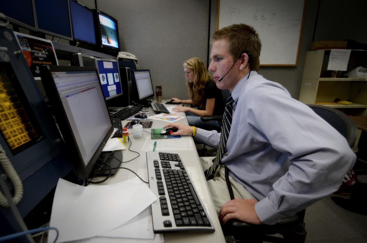
Teams conduct powerup and docking operations for the Sensor Test for Orion Relative Navigation Risk Mitigation (STORRM) in a payload support room at Johnson Space Center’s Mission Control Center in Houston on May 18, 2011. STORMM was successfully demonstrated on Space Shuttle Endeavour’s STS-134 mission to the International Space Station..The goal of STORRM was to validate a new relative navigation sensor based on advanced laser and detector technology that will make docking and undocking spacecraft easier and safer. It also tested the hardware in the same environment that the sensors would experience on the first Orion rendezvous to another vehicle. Part of Batch image transfer from Flickr.

Teams conduct powerup and docking operations for the Sensor Test for Orion Relative Navigation Risk Mitigation (STORRM) in a payload support room at Johnson Space Center’s Mission Control Center in Houston on May 18, 2011. STORMM was successfully demonstrated on Space Shuttle Endeavour’s STS-134 mission to the International Space Station..The goal of STORRM was to validate a new relative navigation sensor based on advanced laser and detector technology that will make docking and undocking spacecraft easier and safer. It also tested the hardware in the same environment that the sensors would experience on the first Orion rendezvous to another vehicle. Part of Batch image transfer from Flickr.

Teams conduct powerup and docking operations for the Sensor Test for Orion Relative Navigation Risk Mitigation (STORRM) in a payload support room at Johnson Space Center’s Mission Control Center in Houston on May 18, 2011. STORRM was successfully demonstrated on Space Shuttle Endeavour’s STS-134 mission to the International Space Station. The goal of STORRM was to validate a new relative navigation sensor based on advanced laser and detector technology that will make docking and undocking spacecraft easier and safer. It also tested the hardware in the same environment that the sensors would experience on the first Orion rendezvous to another vehicle.
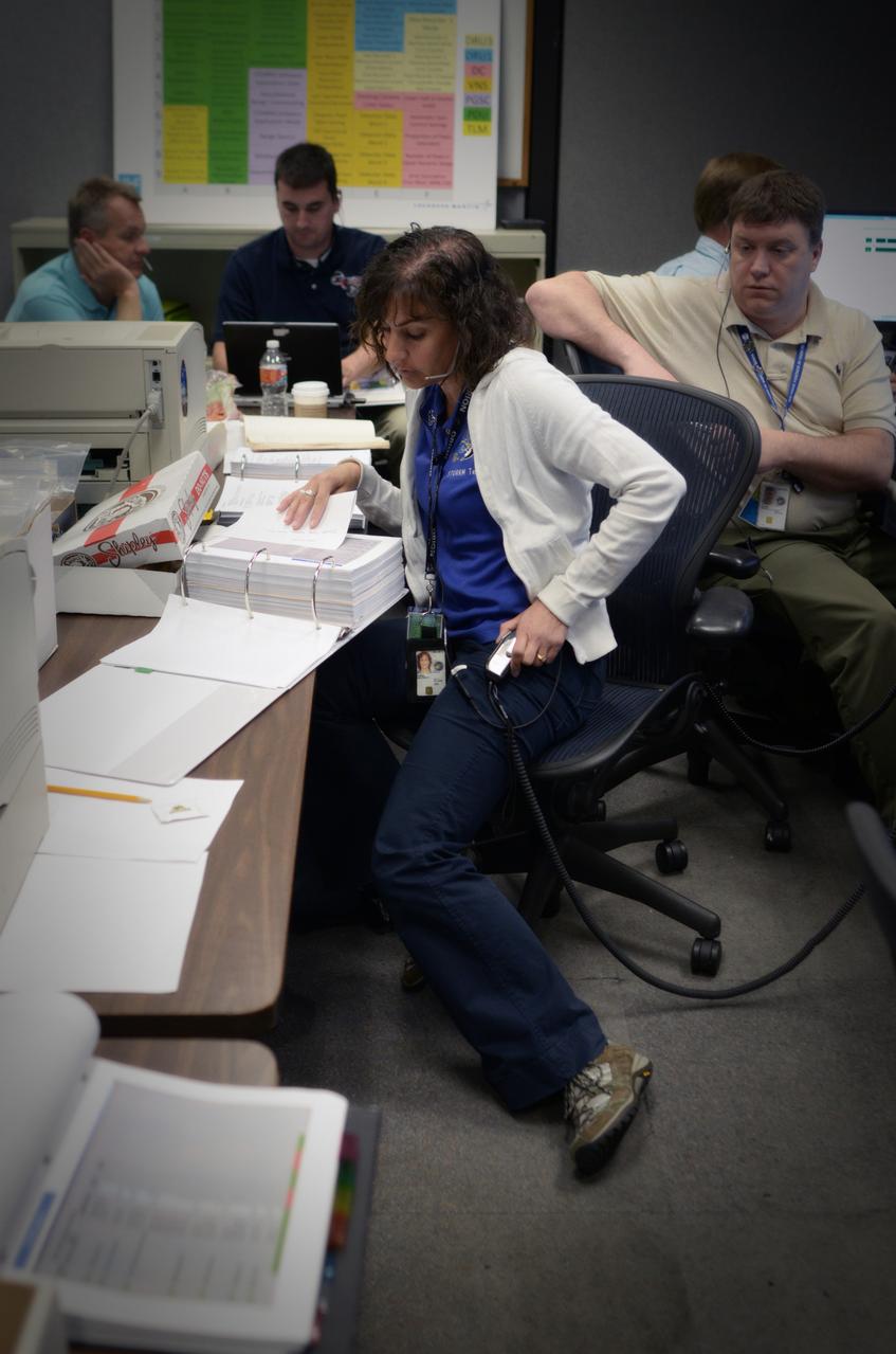
Teams conduct powerup and docking operations for the Sensor Test for Orion Relative Navigation Risk Mitigation (STORRM) in a payload support room at Johnson Space Center’s Mission Control Center in Houston on May 18, 2011. STORMM was successfully demonstrated on Space Shuttle Endeavour’s STS-134 mission to the International Space Station..The goal of STORRM was to validate a new relative navigation sensor based on advanced laser and detector technology that will make docking and undocking spacecraft easier and safer. It also tested the hardware in the same environment that the sensors would experience on the first Orion rendezvous to another vehicle. Part of Batch image transfer from Flickr.
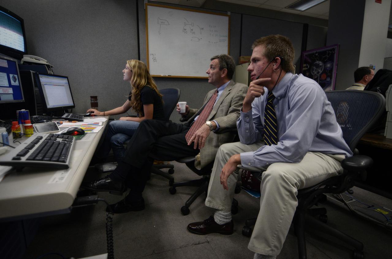
Teams conduct powerup and docking operations for the Sensor Test for Orion Relative Navigation Risk Mitigation (STORRM) in a payload support room at Johnson Space Center’s Mission Control Center in Houston on May 18, 2011. STORRM was successfully demonstrated on Space Shuttle Endeavour’s STS-134 mission to the International Space Station. The goal of STORRM was to validate a new relative navigation sensor based on advanced laser and detector technology that will make docking and undocking spacecraft easier and safer. It also tested the hardware in the same environment that the sensors would experience on the first Orion rendezvous to another vehicle.

Teams conduct powerup and docking operations for the Sensor Test for Orion Relative Navigation Risk Mitigation (STORRM) in a payload support room at Johnson Space Center’s Mission Control Center in Houston on May 18, 2011. STORMM was successfully demonstrated on Space Shuttle Endeavour’s STS-134 mission to the International Space Station..The goal of STORRM was to validate a new relative navigation sensor based on advanced laser and detector technology that will make docking and undocking spacecraft easier and safer. It also tested the hardware in the same environment that the sensors would experience on the first Orion rendezvous to another vehicle. Part of Batch image transfer from Flickr.
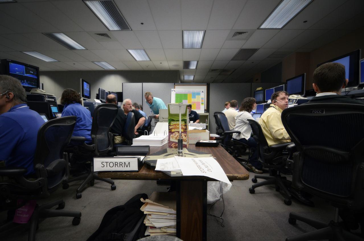
Teams conduct powerup and docking operations for the Sensor Test for Orion Relative Navigation Risk Mitigation (STORRM) in a payload support room at Johnson Space Center’s Mission Control Center in Houston on May 18, 2011. STORMM was successfully demonstrated on Space Shuttle Endeavour’s STS-134 mission to the International Space Station..The goal of STORRM was to validate a new relative navigation sensor based on advanced laser and detector technology that will make docking and undocking spacecraft easier and safer. It also tested the hardware in the same environment that the sensors would experience on the first Orion rendezvous to another vehicle. Part of Batch image transfer from Flickr.
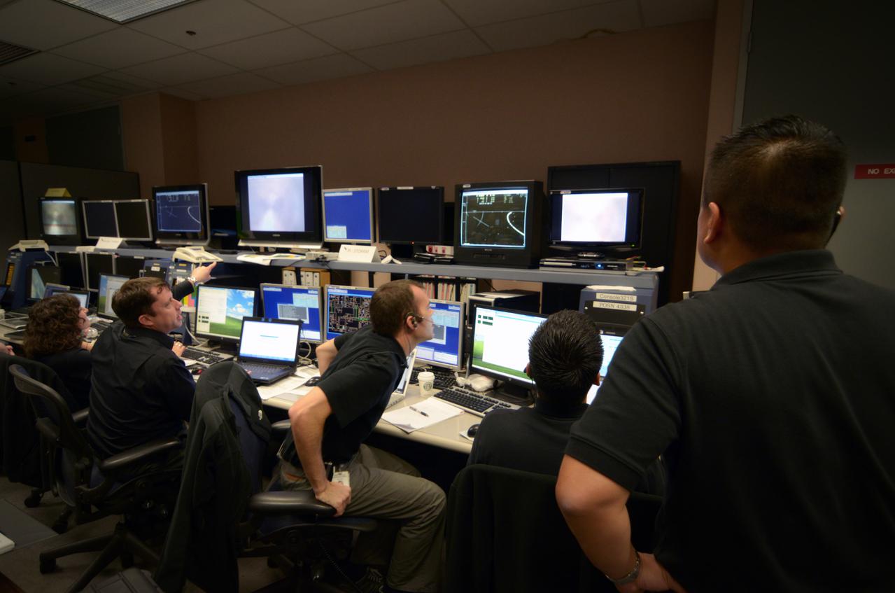
Teams conduct powerup and docking operations for the Sensor Test for Orion Relative Navigation Risk Mitigation (STORRM) in a payload support room at Johnson Space Center’s Mission Control Center in Houston on May 18, 2011. STORMM was successfully demonstrated on Space Shuttle Endeavour’s STS-134 mission to the International Space Station. The goal of STORRM was to validate a new relative navigation sensor based on advanced laser and detector technology that will make docking and undocking spacecraft easier and safer. It also tested the hardware in the same environment that the sensors would experience on the first Orion rendezvous to another vehicle.
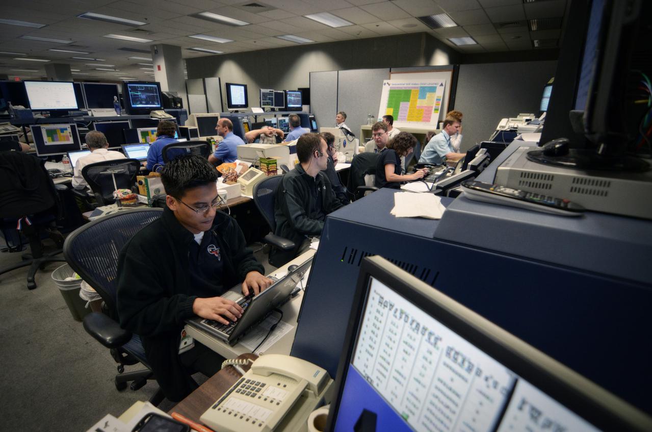
Teams conduct powerup and docking operations for the Sensor Test for Orion Relative Navigation Risk Mitigation (STORRM) in a payload support room at Johnson Space Center’s Mission Control Center in Houston on May 18, 2011. STORRM was successfully demonstrated on Space Shuttle Endeavour’s STS-134 mission to the International Space Station. The goal of STORRM was to validate a new relative navigation sensor based on advanced laser and detector technology that will make docking and undocking spacecraft easier and safer. It also tested the hardware in the same environment that the sensors would experience on the first Orion rendezvous to another vehicle.

Teams conduct powerup and docking operations for the Sensor Test for Orion Relative Navigation Risk Mitigation (STORRM) in a payload support room at Johnson Space Center’s Mission Control Center in Houston on May 18, 2011. STORMM was successfully demonstrated on Space Shuttle Endeavour’s STS-134 mission to the International Space Station..The goal of STORRM was to validate a new relative navigation sensor based on advanced laser and detector technology that will make docking and undocking spacecraft easier and safer. It also tested the hardware in the same environment that the sensors would experience on the first Orion rendezvous to another vehicle. Part of Batch image transfer from Flickr.
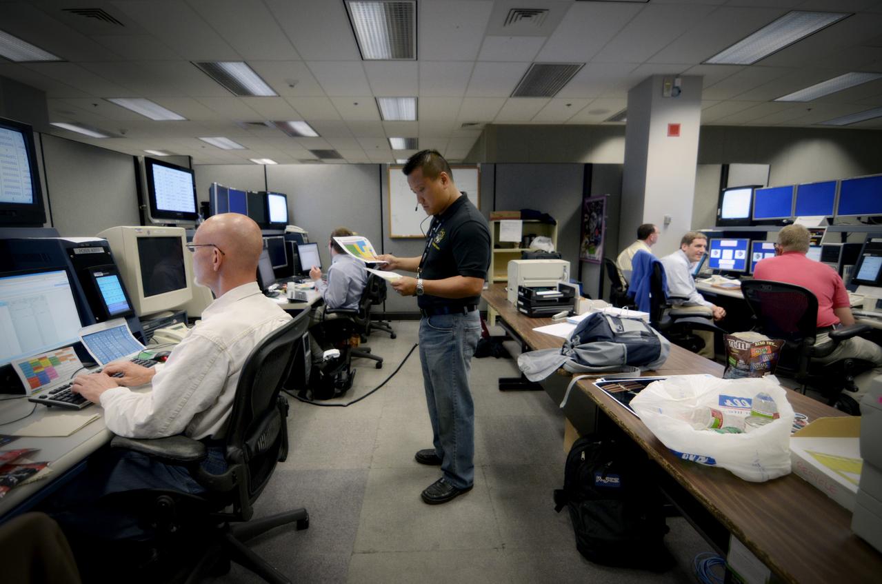
Teams conduct powerup and docking operations for the Sensor Test for Orion Relative Navigation Risk Mitigation (STORRM) in a payload support room at Johnson Space Center’s Mission Control Center in Houston on May 18, 2011. STORMM was successfully demonstrated on Space Shuttle Endeavour’s STS-134 mission to the International Space Station..The goal of STORRM was to validate a new relative navigation sensor based on advanced laser and detector technology that will make docking and undocking spacecraft easier and safer. It also tested the hardware in the same environment that the sensors would experience on the first Orion rendezvous to another vehicle. Part of Batch image transfer from Flickr.
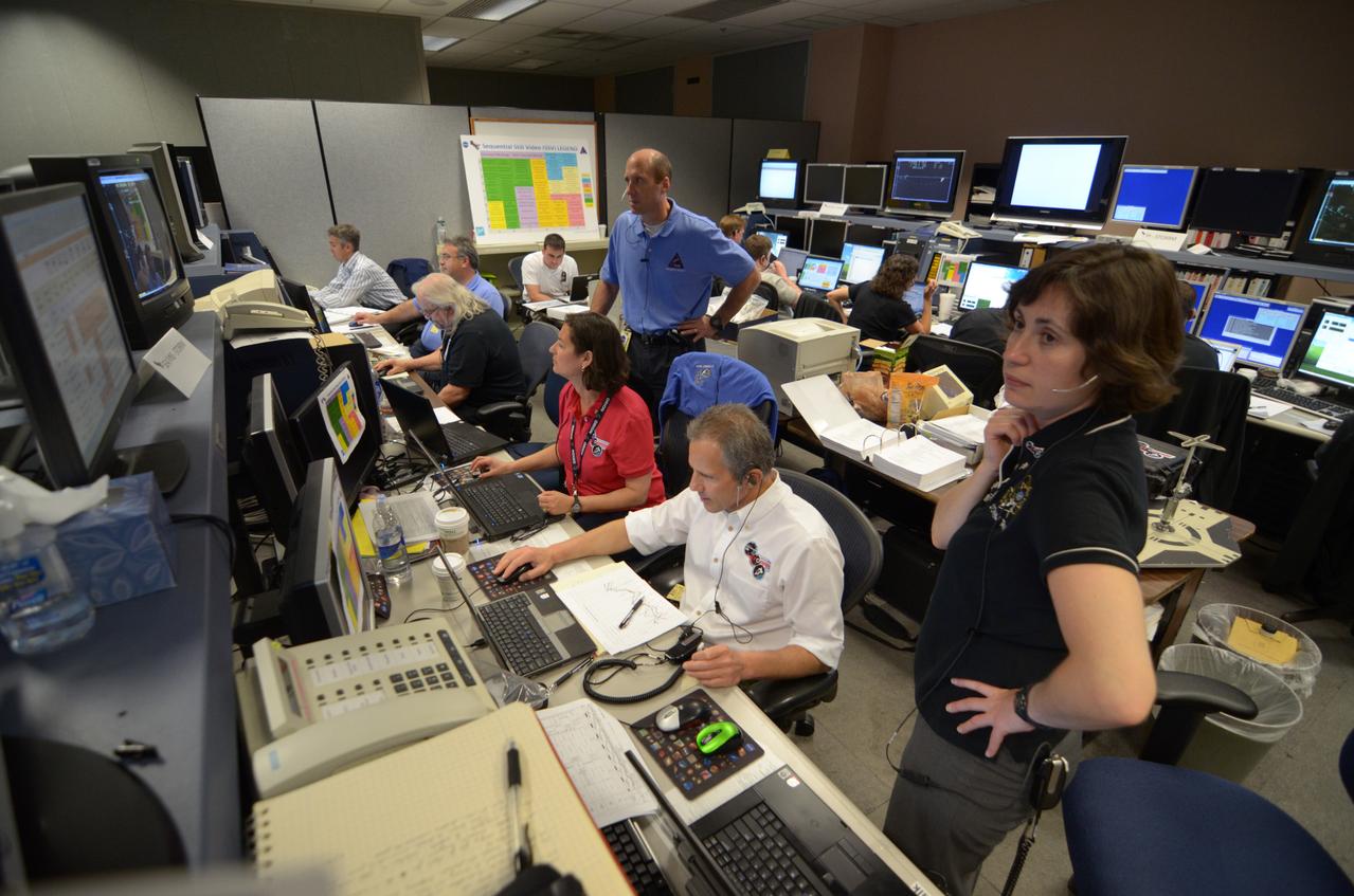
Teams conduct powerup and docking operations for the Sensor Test for Orion Relative Navigation Risk Mitigation (STORRM) in a payload support room at Johnson Space Center’s Mission Control Center in Houston on May 18, 2011. STORMM was successfully demonstrated on Space Shuttle Endeavour’s STS-134 mission to the International Space Station..The goal of STORRM was to validate a new relative navigation sensor based on advanced laser and detector technology that will make docking and undocking spacecraft easier and safer. It also tested the hardware in the same environment that the sensors would experience on the first Orion rendezvous to another vehicle. Part of Batch image transfer from Flickr.
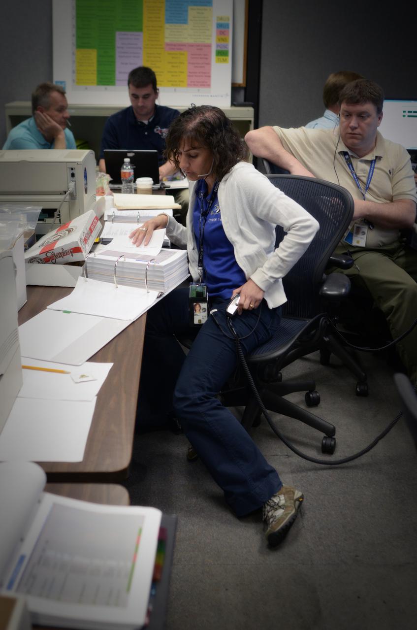
Teams conduct powerup and docking operations for the Sensor Test for Orion Relative Navigation Risk Mitigation (STORRM) in a payload support room at Johnson Space Center’s Mission Control Center in Houston on May 17, 2011. STORRM was successfully demonstrated on Space Shuttle Endeavour’s STS-134 mission to the International Space Station. The goal of STORRM was to validate a new relative navigation sensor based on advanced laser and detector technology that will make docking and undocking spacecraft easier and safer. It also tested the hardware in the same environment that the sensors would experience on the first Orion rendezvous to another vehicle.
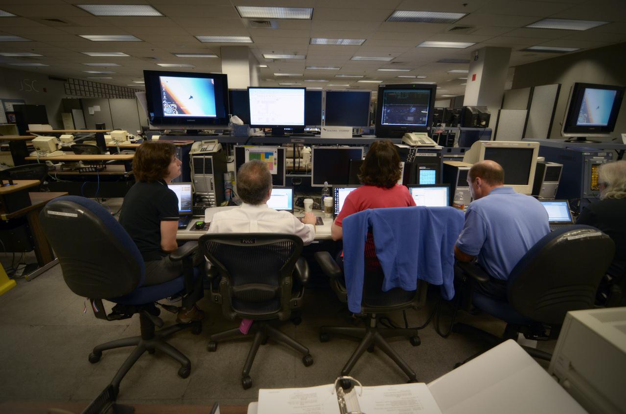
Teams conduct powerup and docking operations for the Sensor Test for Orion Relative Navigation Risk Mitigation (STORRM) in a payload support room at Johnson Space Center’s Mission Control Center in Houston on May 18, 2011. STORRM was successfully demonstrated on Space Shuttle Endeavour’s STS-134 mission to the International Space Station. The goal of STORRM was to validate a new relative navigation sensor based on advanced laser and detector technology that will make docking and undocking spacecraft easier and safer. It also tested the hardware in the same environment that the sensors would experience on the first Orion rendezvous to another vehicle.
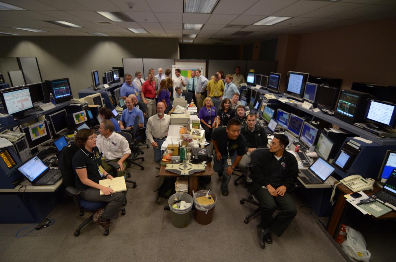
Teams conduct powerup and docking operations for the Sensor Test for Orion Relative Navigation Risk Mitigation (STORRM) in a payload support room at Johnson Space Center’s Mission Control Center in Houston on May 18, 2011. STORRM was successfully demonstrated on Space Shuttle Endeavour’s STS-134 mission to the International Space Station. The goal of STORRM was to validate a new relative navigation sensor based on advanced laser and detector technology that will make docking and undocking spacecraft easier and safer. It also tested the hardware in the same environment that the sensors would experience on the first Orion rendezvous to another vehicle.
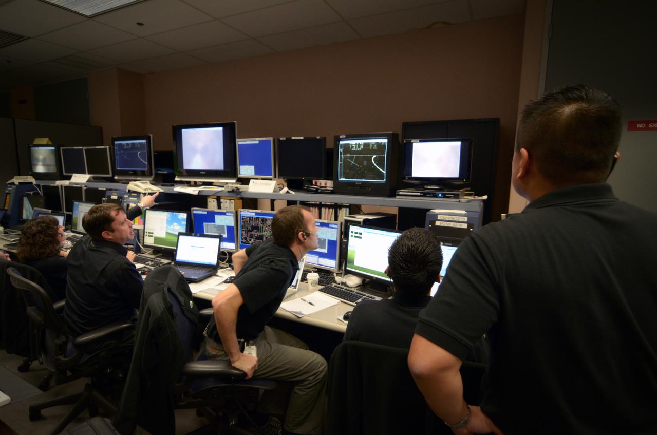
Teams conduct powerup and docking operations for the Sensor Test for Orion Relative Navigation Risk Mitigation (STORRM) in a payload support room at Johnson Space Center’s Mission Control Center in Houston on May 18, 2011. STORMM was successfully demonstrated on Space Shuttle Endeavour’s STS-134 mission to the International Space Station..The goal of STORRM was to validate a new relative navigation sensor based on advanced laser and detector technology that will make docking and undocking spacecraft easier and safer. It also tested the hardware in the same environment that the sensors would experience on the first Orion rendezvous to another vehicle. Part of Batch image transfer from Flickr.
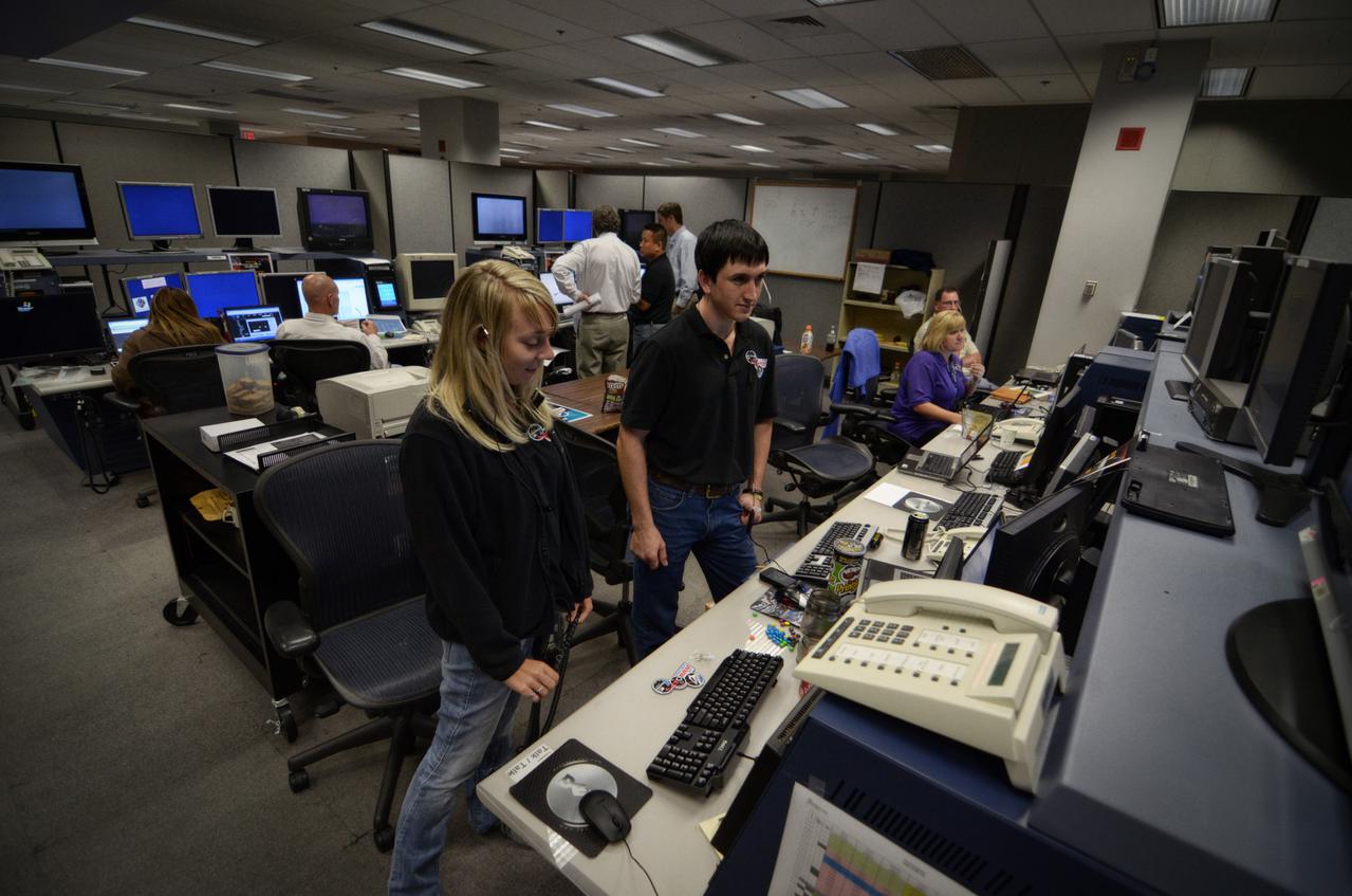
Teams conduct powerup and docking operations for the Sensor Test for Orion Relative Navigation Risk Mitigation (STORRM) in a payload support room at Johnson Space Center’s Mission Control Center in Houston on May 18, 2011. STORRM was successfully demonstrated on Space Shuttle Endeavour’s STS-134 mission to the International Space Station. The goal of STORRM was to validate a new relative navigation sensor based on advanced laser and detector technology that will make docking and undocking spacecraft easier and safer. It also tested the hardware in the same environment that the sensors would experience on the first Orion rendezvous to another vehicle.

Teams conduct powerup and docking operations for the Sensor Test for Orion Relative Navigation Risk Mitigation (STORRM) in a payload support room at Johnson Space Center’s Mission Control Center in Houston on May 18, 2011. STORMM was successfully demonstrated on Space Shuttle Endeavour’s STS-134 mission to the International Space Station..The goal of STORRM was to validate a new relative navigation sensor based on advanced laser and detector technology that will make docking and undocking spacecraft easier and safer. It also tested the hardware in the same environment that the sensors would experience on the first Orion rendezvous to another vehicle. Part of Batch image transfer from Flickr.
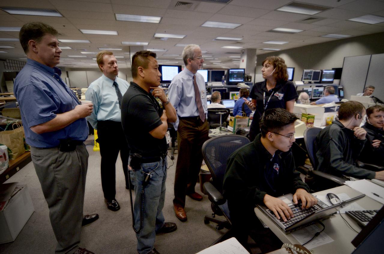
Teams conduct powerup and docking operations for the Sensor Test for Orion Relative Navigation Risk Mitigation (STORRM) in a payload support room at Johnson Space Center’s Mission Control Center in Houston on May 18, 2011. STORMM was successfully demonstrated on Space Shuttle Endeavour’s STS-134 mission to the International Space Station..The goal of STORRM was to validate a new relative navigation sensor based on advanced laser and detector technology that will make docking and undocking spacecraft easier and safer. It also tested the hardware in the same environment that the sensors would experience on the first Orion rendezvous to another vehicle. Part of Batch image transfer from Flickr.
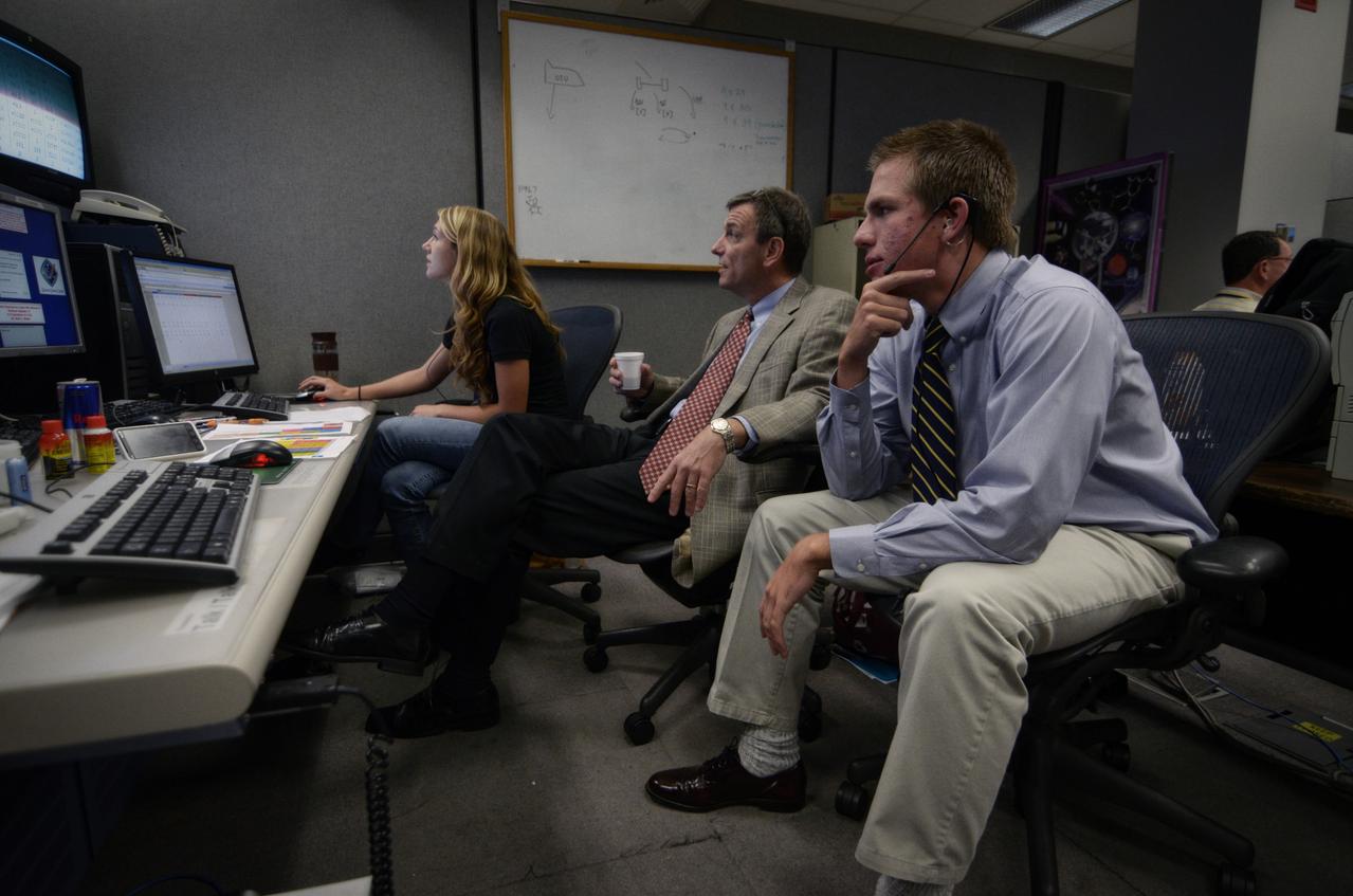
Teams conduct powerup and docking operations for the Sensor Test for Orion Relative Navigation Risk Mitigation (STORRM) in a payload support room at Johnson Space Center’s Mission Control Center in Houston on May 18, 2011. STORMM was successfully demonstrated on Space Shuttle Endeavour’s STS-134 mission to the International Space Station..The goal of STORRM was to validate a new relative navigation sensor based on advanced laser and detector technology that will make docking and undocking spacecraft easier and safer. It also tested the hardware in the same environment that the sensors would experience on the first Orion rendezvous to another vehicle. Part of Batch image transfer from Flickr.
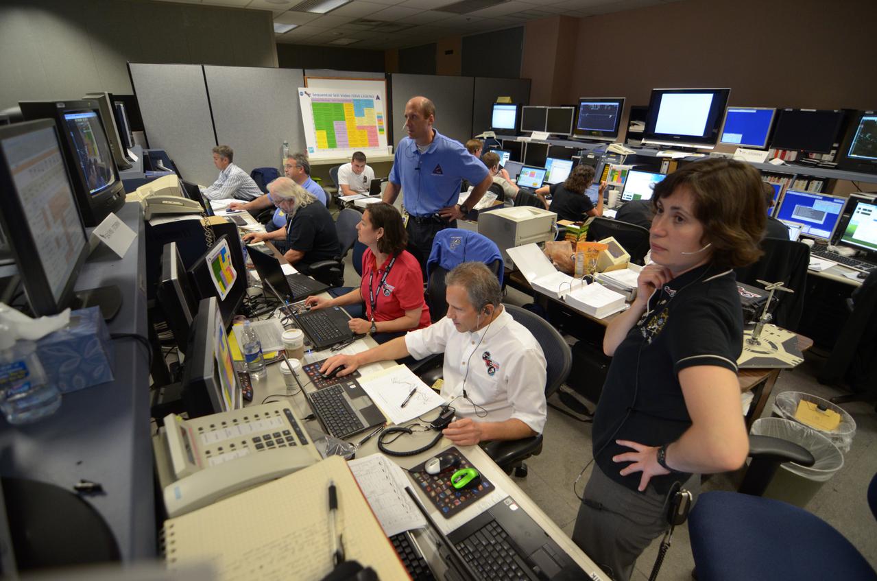
Teams conduct powerup and docking operations for the Sensor Test for Orion Relative Navigation Risk Mitigation (STORRM) in a payload support room at Johnson Space Center’s Mission Control Center in Houston on May 18, 2011. STORRM was successfully demonstrated on Space Shuttle Endeavour’s STS-134 mission to the International Space Station. The goal of STORRM was to validate a new relative navigation sensor based on advanced laser and detector technology that will make docking and undocking spacecraft easier and safer. It also tested the hardware in the same environment that the sensors would experience on the first Orion rendezvous to another vehicle.
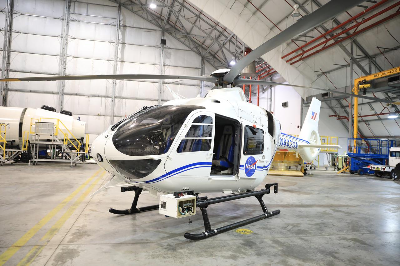
The NASA Airborne Instrumentation for Real-world Video of Urban Environments (AIRVUE) sensor pod is attached to the base of a NASA helicopter at NASA’s Kennedy Space Center in Cape Canaveral, Florida in April 2024 before a flight to test the pod’s cameras and sensors. The AIRVUE pod will be used to collect data for autonomous aircraft like air taxis, drones, or other Advanced Air Mobility aircraft.

KENNEDY SPACE CENTER, FLA. -- On Launch Pad 39A, Lockheed Martin engineer Ray Clark splices wires between space shuttle Atlantis' external tank and the engine cutoff, or ECO, sensor system. The replacement feed-through connector in the ECO sensor system will be installed later. Some of the tank's ECO sensors gave failed readings during propellant tanking for Atlantis' STS-122 mission launch attempts on Dec. 6 and Dec. 9. Results of a tanking test on Dec. 18 pointed to an open circuit in the feed-through connector wiring, which is located at the base of the tank. The feed-through connector passes the wires from the inside of the tank to the outside. The pins in the replacement connector have been precisely soldered to create a connection that allows sensors inside the tank to send signals to the computers onboard Atlantis. No problems with the ECO sensors themselves have been found. NASA's Space Shuttle Program has proposed a target launch date of Feb. 7 for the STS-122 mission. That proposed launch date remains under evaluation pending coordination with all partners in the International Space Station Program. Photo credit: NASA/George Shelton
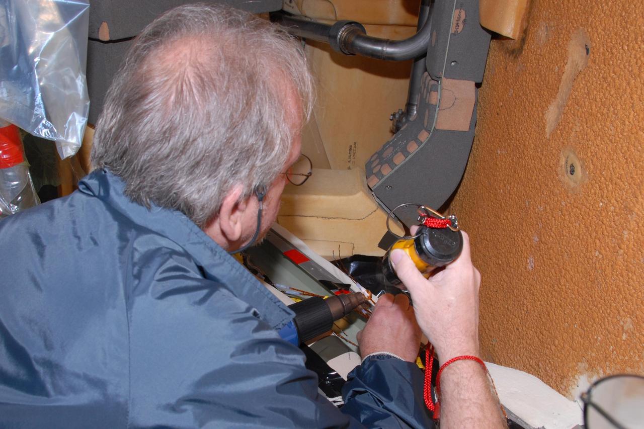
KENNEDY SPACE CENTER, FLA. -- On Launch Pad 39A, Lockheed Martin engineer Ray Clark splices wires between space shuttle Atlantis' external tank and the engine cutoff, or ECO, sensor system. The replacement feed-through connector in the ECO sensor system will be installed later. Some of the tank's ECO sensors gave failed readings during propellant tanking for Atlantis' STS-122 mission launch attempts on Dec. 6 and Dec. 9. Results of a tanking test on Dec. 18 pointed to an open circuit in the feed-through connector wiring, which is located at the base of the tank. The feed-through connector passes the wires from the inside of the tank to the outside. The pins in the replacement connector have been precisely soldered to create a connection that allows sensors inside the tank to send signals to the computers onboard Atlantis. No problems with the ECO sensors themselves have been found. NASA's Space Shuttle Program has proposed a target launch date of Feb. 7 for the STS-122 mission. That proposed launch date remains under evaluation pending coordination with all partners in the International Space Station Program. Photo credit: NASA/George Shelton
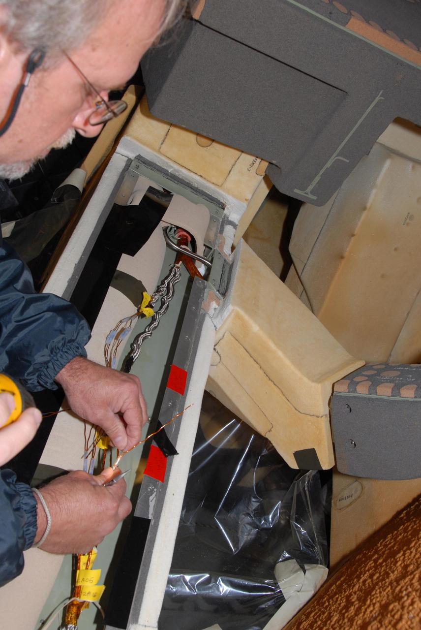
KENNEDY SPACE CENTER, FLA. -- On Launch Pad 39A, Lockheed Martin engineer Ray Clark splices wires between space shuttle Atlantis' external tank and the engine cutoff, or ECO, sensor system. The replacement feed-through connector in the ECO sensor system will be installed later. Some of the tank's ECO sensors gave failed readings during propellant tanking for Atlantis' STS-122 mission launch attempts on Dec. 6 and Dec. 9. Results of a tanking test on Dec. 18 pointed to an open circuit in the feed-through connector wiring, which is located at the base of the tank. The feed-through connector passes the wires from the inside of the tank to the outside. The pins in the replacement connector have been precisely soldered to create a connection that allows sensors inside the tank to send signals to the computers onboard Atlantis. No problems with the ECO sensors themselves have been found. NASA's Space Shuttle Program has proposed a target launch date of Feb. 7 for the STS-122 mission. That proposed launch date remains under evaluation pending coordination with all partners in the International Space Station Program. Photo credit: NASA/George Shelton

KENNEDY SPACE CENTER, FLA. -- On Launch Pad 39A at NASA's Kennedy Space Center, foam insulation is being trimmed for placement around the engine cutoff, or ECO, sensor system connector and wiring on space shuttle Atlantis' external tank. The foam was removed to enable engineers to remove and replace a feed-through ECO sensor connector on the tank. The feed-through connector passes the wires from the inside of the tank to the outside. Results of a tanking test on Dec. 18 pointed to an open circuit in the feed-through connector wiring, which is located at the base of the tank. The pins in the replacement connector were precisely soldered to create a connection that allows sensors inside the tank to send signals to the computers onboard Atlantis. The launch date for the shuttle's STS-122 mission has now been targeted for Feb. 7. Photo credit: NASA/Kim Shiflett
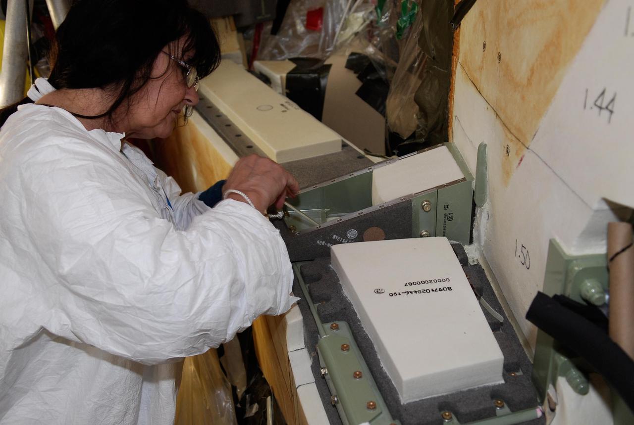
KENNEDY SPACE CENTER, FLA. -- On Launch Pad 39A at NASA's Kennedy Space Center, a technician trims foam placed around the engine cutoff, or ECO, sensor system connector and wiring on space shuttle Atlantis' external tank. The foam was removed to enable engineers to remove and replace a feed-through ECO sensor connector on the tank. The feed-through connector passes the wires from the inside of the tank to the outside. Results of a tanking test on Dec. 18 pointed to an open circuit in the feed-through connector wiring, which is located at the base of the tank. The pins in the replacement connector were precisely soldered to create a connection that allows sensors inside the tank to send signals to the computers onboard Atlantis. The launch date for the shuttle's STS-122 mission has now been targeted for Feb. 7. Photo credit: NASA/Kim Shiflett

KENNEDY SPACE CENTER, FLA. -- On Launch Pad 39A at NASA's Kennedy Space Center, foam is being replaced around the engine cutoff, or ECO, sensor system connector and wiring on space shuttle Atlantis' external tank. The foam was removed to enable engineers to remove and replace a feed-through ECO sensor connector on the tank. The feed-through connector passes the wires from the inside of the tank to the outside. Results of a tanking test on Dec. 18 pointed to an open circuit in the feed-through connector wiring, which is located at the base of the tank. The pins in the replacement connector were precisely soldered to create a connection that allows sensors inside the tank to send signals to the computers onboard Atlantis. The launch date for the shuttle's STS-122 mission has now been targeted for Feb. 7. Photo credit: NASA/Kim Shiflett
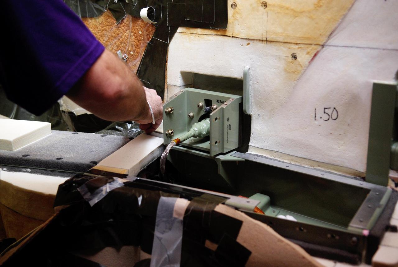
KENNEDY SPACE CENTER, FLA. -- On Launch Pad 39A at NASA's Kennedy Space Center, foam insulation is being trimmed for placement around the engine cutoff, or ECO, sensor system connector and wiring on space shuttle Atlantis' external tank. The foam was removed to enable engineers to remove and replace a feed-through ECO sensor connector on the tank. The feed-through connector passes the wires from the inside of the tank to the outside. Results of a tanking test on Dec. 18 pointed to an open circuit in the feed-through connector wiring, which is located at the base of the tank. The pins in the replacement connector were precisely soldered to create a connection that allows sensors inside the tank to send signals to the computers onboard Atlantis. The launch date for the shuttle's STS-122 mission has now been targeted for Feb. 7. Photo credit: NASA/Kim Shiflett
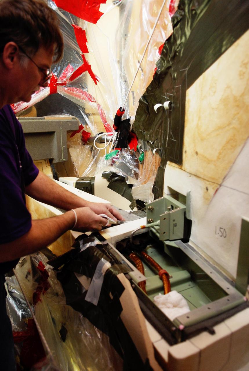
KENNEDY SPACE CENTER, FLA. -- On Launch Pad 39A at NASA's Kennedy Space Center, foam insulation is being trimmed for placement around the engine cutoff, or ECO, sensor system connector and wiring on space shuttle Atlantis' external tank. The foam was removed to enable engineers to remove and replace a feed-through ECO sensor connector on the tank. The feed-through connector passes the wires from the inside of the tank to the outside. Results of a tanking test on Dec. 18 pointed to an open circuit in the feed-through connector wiring, which is located at the base of the tank. The pins in the replacement connector were precisely soldered to create a connection that allows sensors inside the tank to send signals to the computers onboard Atlantis. The launch date for the shuttle's STS-122 mission has now been targeted for Feb. 7. Photo credit: NASA/Kim Shiflett
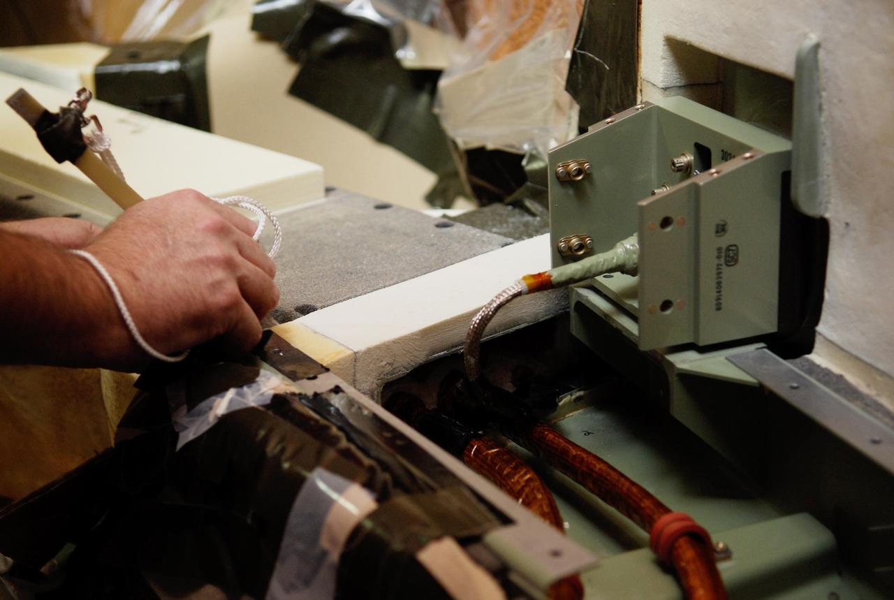
KENNEDY SPACE CENTER, FLA. -- On Launch Pad 39A at NASA's Kennedy Space Center, foam insulation is being trimmed for placement around the engine cutoff, or ECO, sensor system connector and wiring on space shuttle Atlantis' external tank. The foam was removed to enable engineers to remove and replace a feed-through ECO sensor connector on the tank. The feed-through connector passes the wires from the inside of the tank to the outside. Results of a tanking test on Dec. 18 pointed to an open circuit in the feed-through connector wiring, which is located at the base of the tank. The pins in the replacement connector were precisely soldered to create a connection that allows sensors inside the tank to send signals to the computers onboard Atlantis. The launch date for the shuttle's STS-122 mission has now been targeted for Feb. 7. Photo credit: NASA/Kim Shiflett
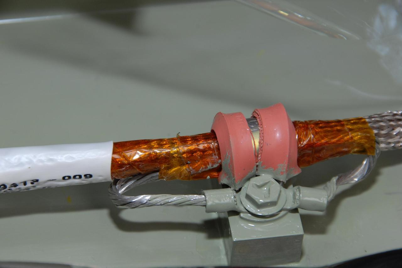
KENNEDY SPACE CENTER, FLA. -- This closeup shows the final splicing completed on the wiring between space shuttle Atlantis' external tank and the engine cutoff, or ECO, sensor system before the replacement feed-through connector in the ECO sensor system is installed. Cryogenic shielding is installed around the wiring. The feed-through connector passes the wires from the inside of the tank to the outside. Results of a tanking test on Dec. 18 pointed to an open circuit in the feed-through connector wiring, which is located at the base of the tank. The pins in the replacement connector have been precisely soldered to create a connection that allows sensors inside the tank to send signals to the computers onboard Atlantis. The work is being done on Launch Pad 39A. Space shuttle Atlantis is now targeted for launch on Feb. 7. Photo credit: NASA/George Shelton
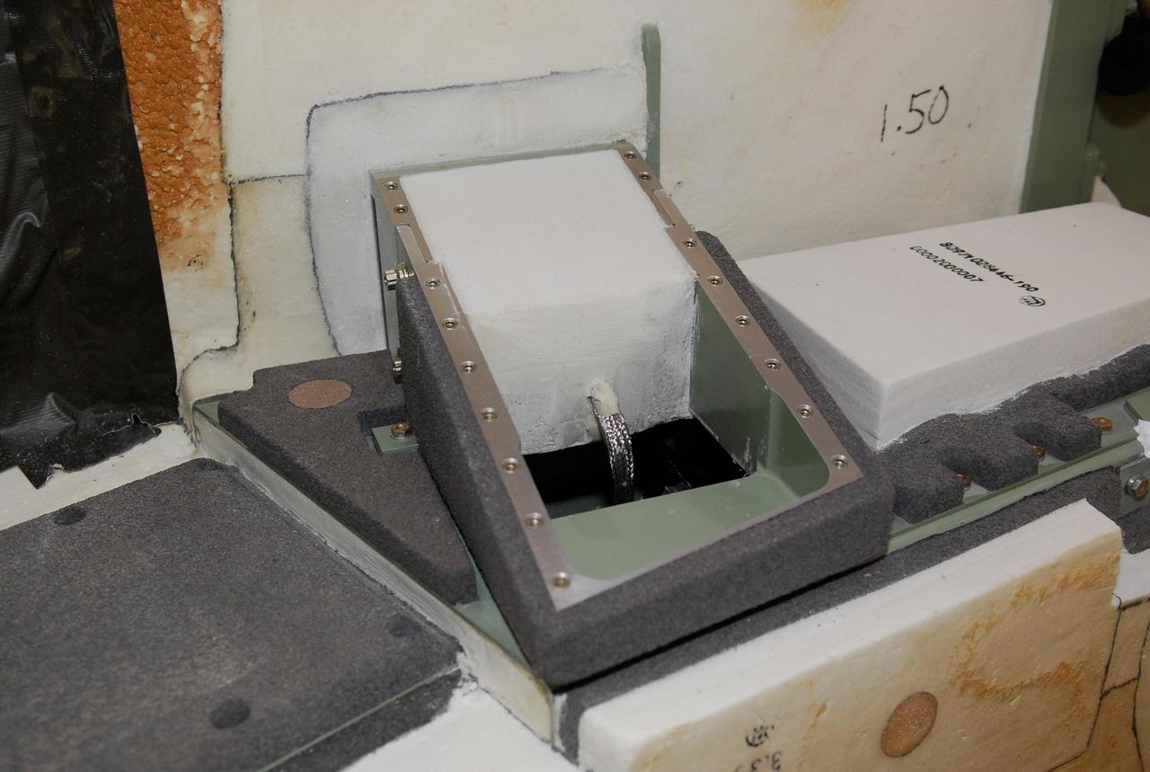
KENNEDY SPACE CENTER, FLA. -- On Launch Pad 39A at NASA's Kennedy Space Center, foam is being replaced around the engine cutoff, or ECO, sensor system connector and wiring on space shuttle Atlantis' external tank. The foam was removed to enable engineers to remove and replace a feed-through ECO sensor connector on the tank. The feed-through connector passes the wires from the inside of the tank to the outside. Results of a tanking test on Dec. 18 pointed to an open circuit in the feed-through connector wiring, which is located at the base of the tank. The pins in the replacement connector were precisely soldered to create a connection that allows sensors inside the tank to send signals to the computers onboard Atlantis. The launch date for the shuttle's STS-122 mission has now been targeted for Feb. 7. Photo credit: NASA/Kim Shiflett

CAPE CANAVERAL, Fla. – At the Astrotech payload processing facility in Titusville, Fla., the Space Tracking and Surveillance System – Demonstrators, or STSS Demo, spacecraft is under a protective cover before being encased in the transportation canister. The STSS Demo is a space-based sensor component of a layered Ballistic Missile Defense System designed for the overall mission of detecting, tracking and discriminating ballistic missiles. STSS is capable of tracking objects after boost phase and provides trajectory information to other sensors. It will be launched by NASA for the Missile Defense Agency between 8 and 8:58 a.m. EDT Sept. 18. Approved for Public Release 09-MDA-04886 (10 SEPT 09) Photo credit: NASA/Kim Shiflett
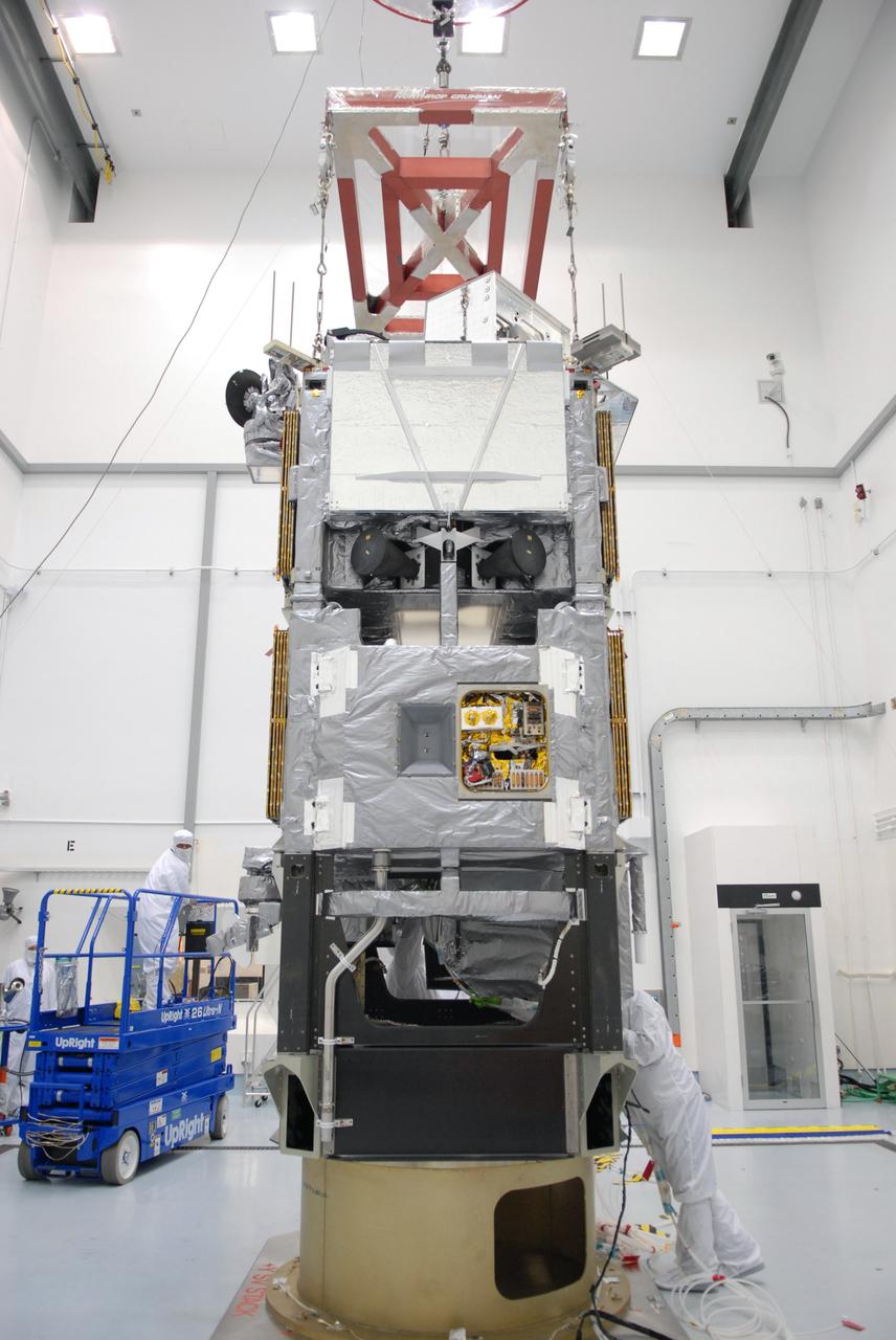
CAPE CANAVERAL, Fla. – At the Astrotech payload processing facility in Titusville, Fla., the SV1-SV2 spacecraft is ready to be weighed. The two spacecraft are known as the Space Tracking and Surveillance System – Demonstrators, or STSS Demo, which is a space-based sensor component of a layered Ballistic Missile Defense System designed for the overall mission of detecting, tracking and discriminating ballistic missiles. STSS is capable of tracking objects after boost phase and provides trajectory information to other sensors. It will be launched by NASA for the Missile Defense Agency between 8 and 8:58 a.m. EDT Sept. 18. Approved for Public Release 09-MDA-04886 (10 SEPT 09) Photo credit: NASA/Jim Grossmann
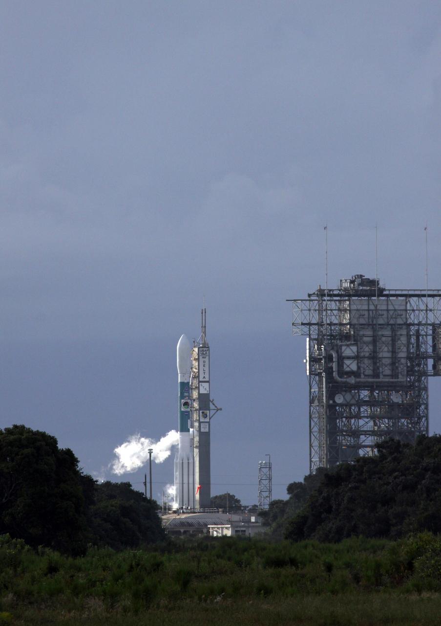
CAPE CANAVERAL, Fla. – On Launch Pad 17-B at Cape Canaveral Air Force Station in Florida, the Space Tracking and Surveillance System Demonstrator spacecraft waits for launch under dark, cloudy sky. Rain over Central Florida's east coast caused the scrub of the launch. STSS Demo is a space-based sensor component of a layered Ballistic Missile Defense System designed for the overall mission of detection, tracking and discriminating ballistic missiles. STSS is capable of tracking objects after boost phase and provides trajectory information to other sensors. It will be launched by NASA for the Missile Defense Agency between 8 and 8:58 a.m. EDT Sept. 24. Photo credit: NASA/Jack Pfaller

CAPE CANAVERAL, Fla. – At the Astrotech payload processing facility in Titusville, Fla., workers place the second row of segments of the transportation canister around the Space Tracking and Surveillance System – Demonstrators, or STSS Demo, spacecraft. The STSS Demo is a space-based sensor component of a layered Ballistic Missile Defense System designed for the overall mission of detecting, tracking and discriminating ballistic missiles. STSS is capable of tracking objects after boost phase and provides trajectory information to other sensors. It will be launched by NASA for the Missile Defense Agency between 8 and 8:58 a.m. EDT Sept. 18. Approved for Public Release 09-MDA-04886 (10 SEPT 09) Photo credit: NASA/Kim Shiflett
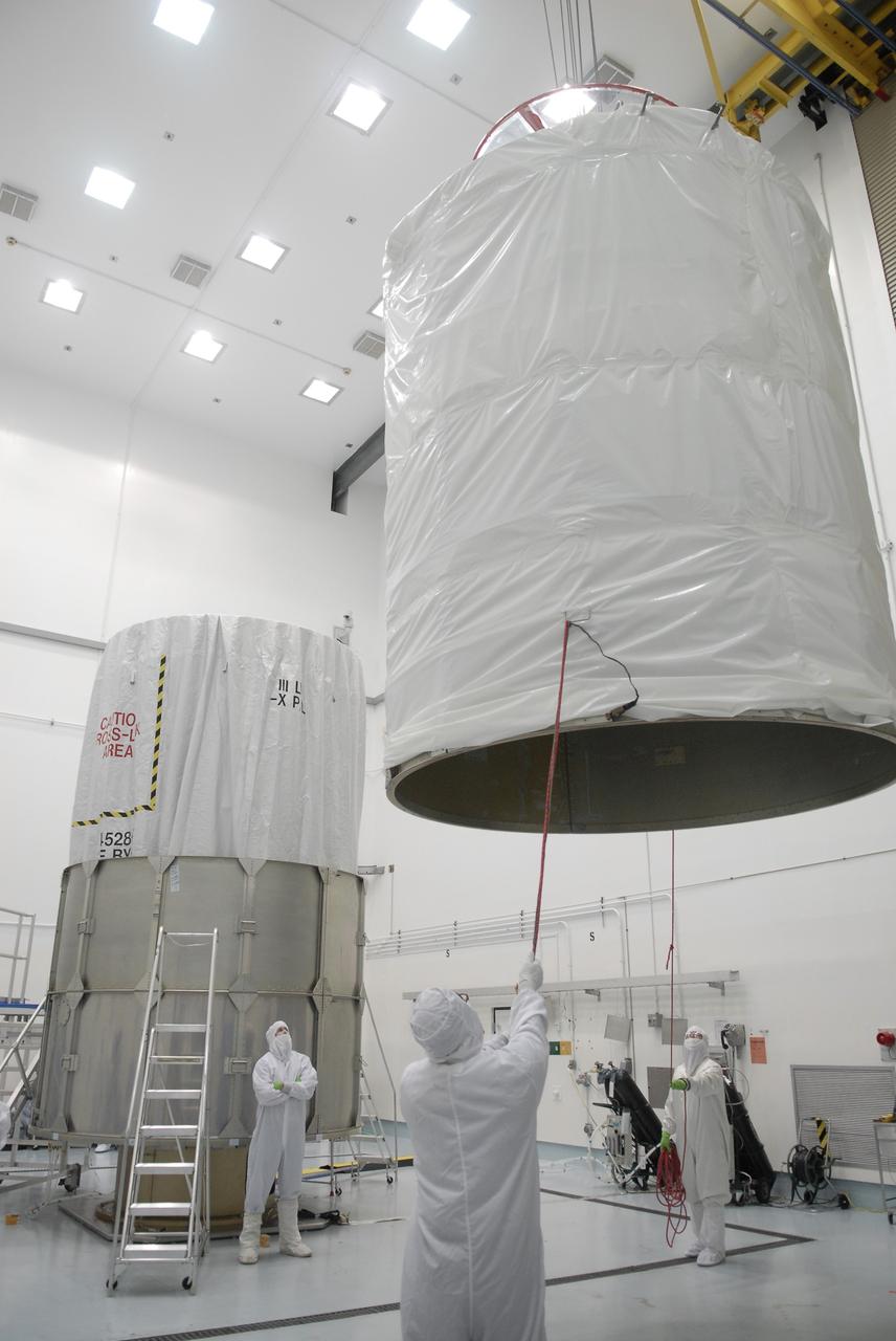
CAPE CANAVERAL, Fla. – At the Astrotech payload processing facility in Titusville, Fla., the upper segment of the transportation canister is moved toward the Space Tracking and Surveillance System – Demonstrators, or STSS Demo, spacecraft, at left. The STSS Demo is a space-based sensor component of a layered Ballistic Missile Defense System designed for the overall mission of detecting, tracking and discriminating ballistic missiles. STSS is capable of tracking objects after boost phase and provides trajectory information to other sensors. It will be launched by NASA for the Missile Defense Agency between 8 and 8:58 a.m. EDT Sept. 18. Approved for Public Release 09-MDA-04886 (10 SEPT 09) Photo credit: NASA/Kim Shiflett

CAPE CANAVERAL, Fla. – Approaching rain clouds at dawn hover over Central Florida's east coast, effectively causing the scrub of the Space Tracking and Surveillance System - Demonstrator spacecraft from Launch Pad 17-B at Cape Canaveral Air Force Station. STSS Demo is a space-based sensor component of a layered Ballistic Missile Defense System designed for the overall mission of detection, tracking and discriminating ballistic missiles. STSS is capable of tracking objects after boost phase and provides trajectory information to other sensors. It will be launched by NASA for the Missile Defense Agency between 8 and 8:58 a.m. EDT Sept. 24. Photo credit: NASA/Jack Pfaller
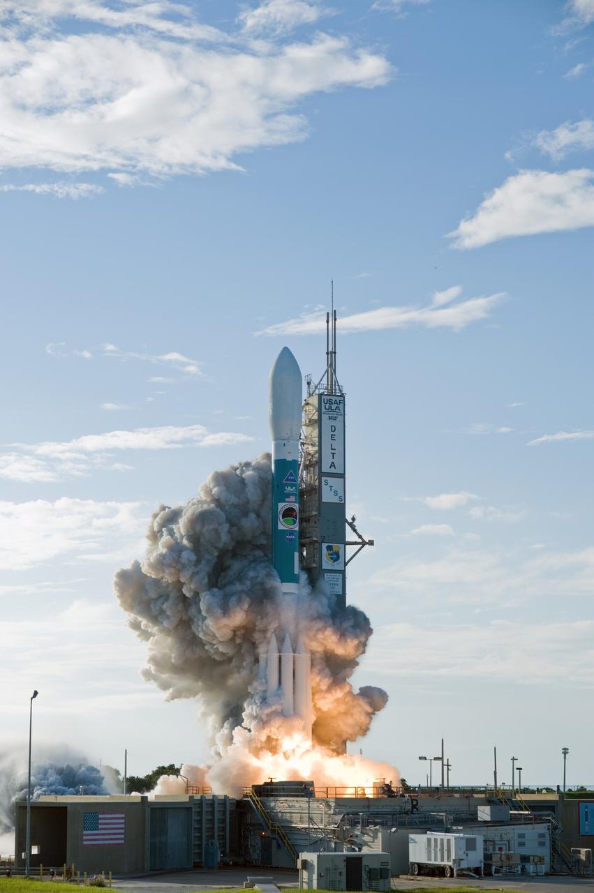
CAPE CANAVERAL, Fla. – The United Launch Alliance Delta II rocket with Space Tracking and Surveillance System - Demonstrator, or STSS-Demo, spacecraft leaps from Launch Pad 17-B at Cape Canaveral Air Force Station amid clouds of smoke. STSS-Demo was launched at 8:20:22 a.m. EDT by NASA for the U.S. Missile Defense Agency. The STSS-Demo is a space-based sensor component of a layered Ballistic Missile Defense System designed for the overall mission of detecting, tracking and discriminating ballistic missiles. STSS is capable of tracking objects after boost phase and provides trajectory information to other sensors. Photo credit: NASA/Sandra Joseph- Kevin O'Connell

CAPE CANAVERAL, Fla. –The United Launch Alliance Delta II rocket with Space Tracking and Surveillance System - Demonstrator, or STSS-Demo, spacecraft leaps from Launch Pad 17-B at Cape Canaveral Air Force Station amid clouds of smoke. STSS-Demo was launched at 8:20:22 a.m. EDT by NASA for the U.S. Missile Defense Agency. The STSS-Demo is a space-based sensor component of a layered Ballistic Missile Defense System designed for the overall mission of detecting, tracking and discriminating ballistic missiles. STSS is capable of tracking objects after boost phase and provides trajectory information to other sensors. Photo credit: NASA/Tony Gray-Tim Powers
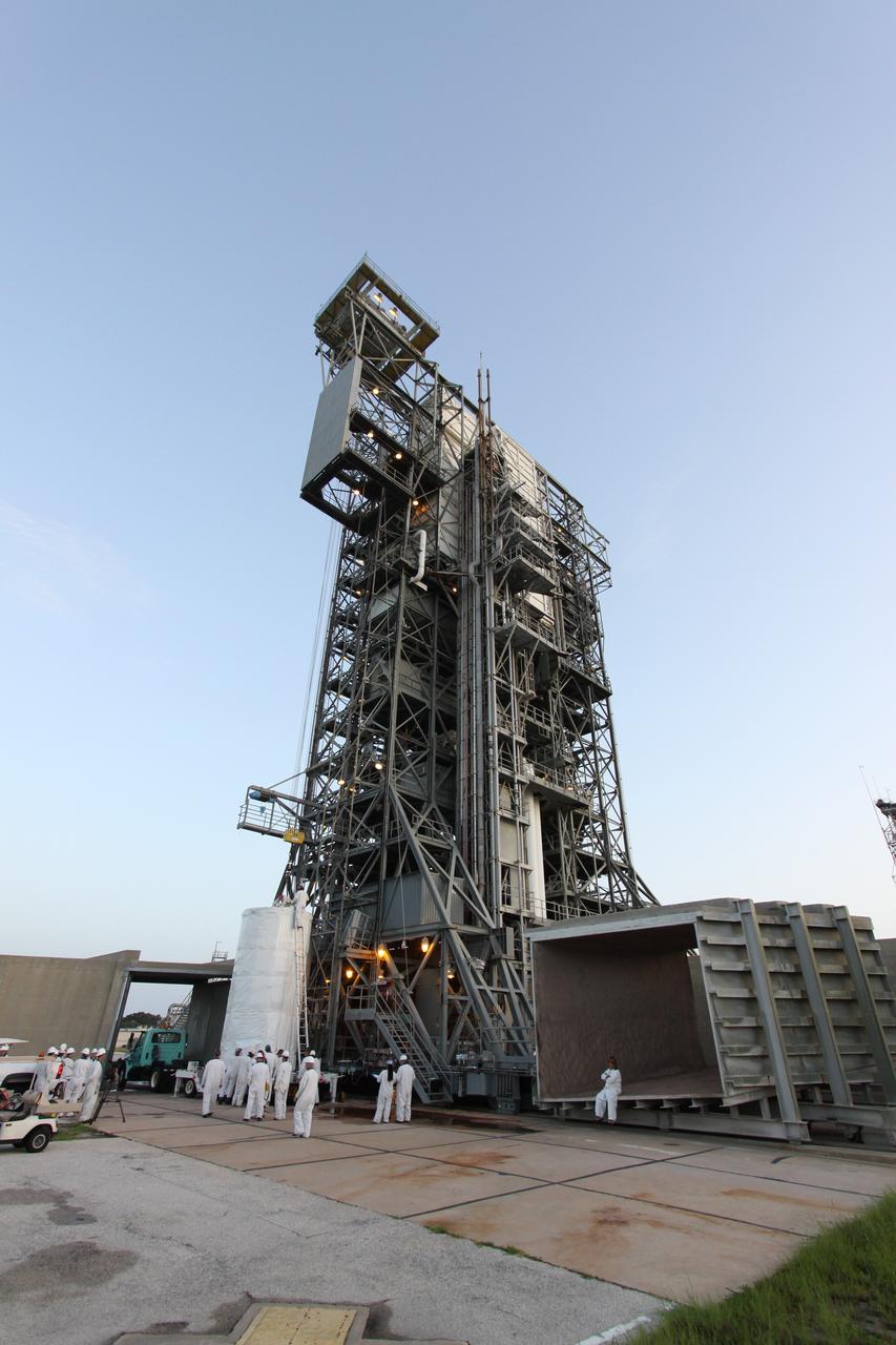
CAPE CANAVERAL, Fla. – The enclosed Space Tracking and Surveillance System – Demonstrators, or STSS-Demo, spacecraft arrives on Cape Canaveral Air Force Station's Launch Pad 17-B. The STSS Demo is a space-based sensor component of a layered Ballistic Missile Defense System designed for the overall mission of detecting, tracking and discriminating ballistic missiles. STSS is capable of tracking objects after boost phase and provides trajectory information to other sensors. It will be launched by NASA for the Missile Defense Agency between 8 and 8:58 a.m. EDT Sept. 18. Approved for Public Release 09-MDA-04886 (10 SEPT 09) Photo credit: NASA/Jack Pfaller

CAPE CANAVERAL, Fla. – The United Launch Alliance Delta II rocket with Space Tracking and Surveillance System - Demonstrator, or STSS-Demo, spacecraft aboard races into the sky leaving a trail of fire and smoke after liftoff from Launch Pad 17-B at Cape Canaveral Air Force Station. It was launched by NASA for the U.S. Missile Defense Agency at 8:20:22 a.m. EDT. The STSS-Demo is a space-based sensor component of a layered Ballistic Missile Defense System designed for the overall mission of detecting, tracking and discriminating ballistic missiles. STSS is capable of tracking objects after boost phase and provides trajectory information to other sensors. Photo credit: NASA/Alan Ault
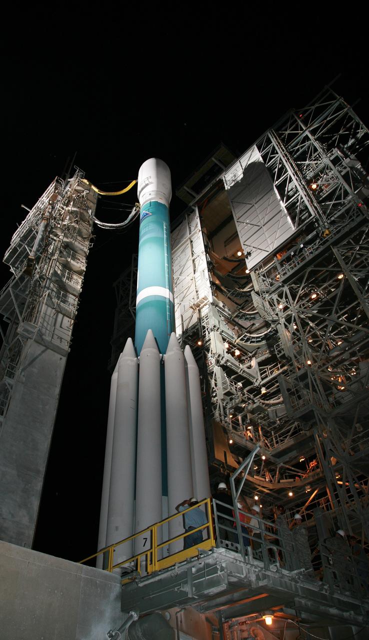
CAPE CANAVERAL, Fla. – The mobile service tower on Launch Pad 17-B at Cape Canaveral Air Force Station rolls back to reveal the United Launch Alliance Delta II rocket that will launch the Space Tracking and Surveillance System - Demonstrator into orbit. It is being launched by NASA for the Missile Defense System. The hour-long launch window opens at 8 a.m. EDT today. The STSS Demo is a space-based sensor component of a layered Ballistic Missile Defense System designed for the overall mission of detecting, tracking and discriminating ballistic missiles. STSS is capable of tracking objects after boost phase and provides trajectory information to other sensors. Photo credit: NASA/Dimitri Gerondidakis

CAPE CANAVERAL, Fla. – The Space Tracking and Surveillance System - Demonstrator, or STSS-Demo, spacecraft lifts off through a cloud of smoke from Launch Pad 17-B at Cape Canaveral Air Force Station aboard a United Launch Alliance Delta II rocket. It was launched by NASA for the U.S. Missile Defense Agency. Launch was at 8:20:22 a.m. EDT. The STSS-Demo is a space-based sensor component of a layered Ballistic Missile Defense System designed for the overall mission of detecting, tracking and discriminating ballistic missiles. STSS is capable of tracking objects after boost phase and provides trajectory information to other sensors. Photo credit: NASA/Jack Pfaller
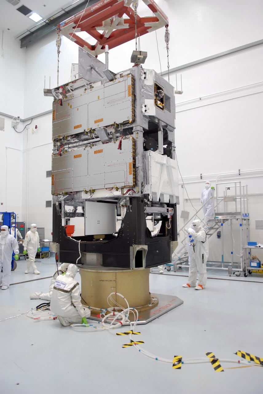
CAPE CANAVERAL, Fla. – At the Astrotech payload processing facility in Titusville, Fla., workers observe as the SV1-SV2 spacecraft is lifted for weighing. The two spacecraft are known as the Space Tracking and Surveillance System – Demonstrators, or STSS Demo, which is a space-based sensor component of a layered Ballistic Missile Defense System designed for the overall mission of detecting, tracking and discriminating ballistic missiles. STSS is capable of tracking objects after boost phase and provides trajectory information to other sensors. It will be launched by NASA for the Missile Defense Agency between 8 and 8:58 a.m. EDT Sept. 18. Approved for Public Release 09-MDA-04886 (10 SEPT 09) Photo credit: NASA/Jim Grossmann
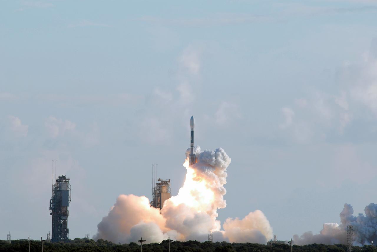
CAPE CANAVERAL, Fla. – The Space Tracking and Surveillance System - Demonstrator, or STSS-Demo, spacecraft lifts off through a cloud of smoke from Launch Pad 17-B at Cape Canaveral Air Force Station aboard a United Launch Alliance Delta II rocket. It was launched by NASA for the U.S. Missile Defense Agency. Launch was at 8:20:22 a.m. EDT. The STSS-Demo is a space-based sensor component of a layered Ballistic Missile Defense System designed for the overall mission of detecting, tracking and discriminating ballistic missiles. STSS is capable of tracking objects after boost phase and provides trajectory information to other sensors. Photo credit: NASA/Alan Ault
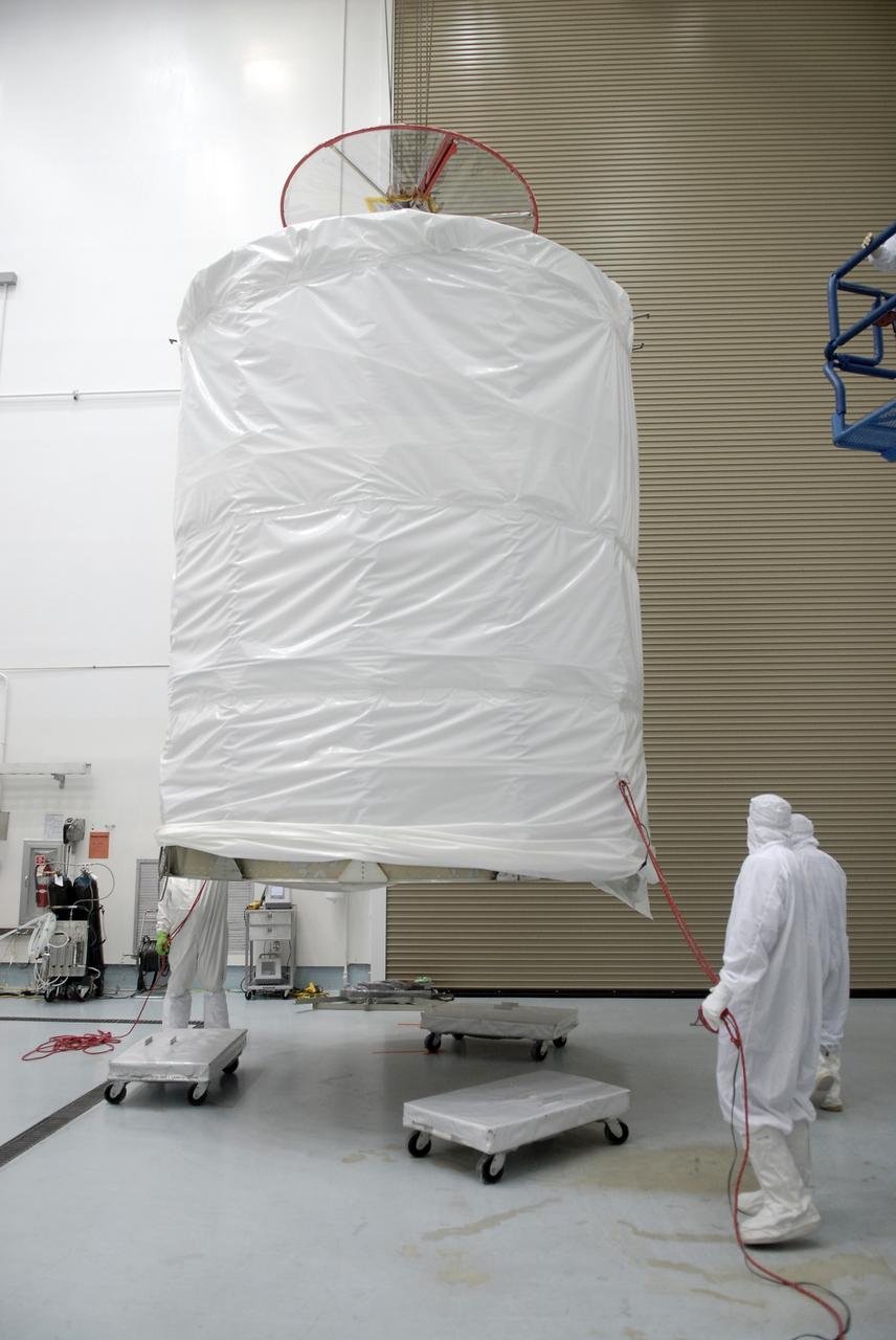
CAPE CANAVERAL, Fla. – At the Astrotech payload processing facility in Titusville, Fla., the upper segment of the transportation canister is lifted to be placed on the top of the Space Tracking and Surveillance System – Demonstrators, or STSS Demo, spacecraft. The STSS Demo is a space-based sensor component of a layered Ballistic Missile Defense System designed for the overall mission of detecting, tracking and discriminating ballistic missiles. STSS is capable of tracking objects after boost phase and provides trajectory information to other sensors. It will be launched by NASA for the Missile Defense Agency between 8 and 8:58 a.m. EDT Sept. 18. Approved for Public Release 09-MDA-04886 (10 SEPT 09) Photo credit: NASA/Kim Shiflett
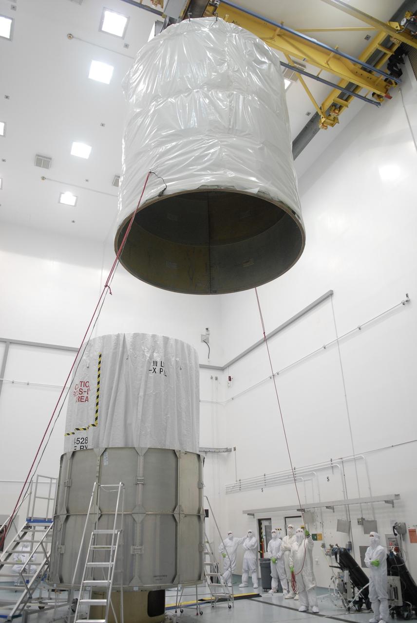
CAPE CANAVERAL, Fla. – At the Astrotech payload processing facility in Titusville, Fla., the upper segment of the transportation canister is moved toward the Space Tracking and Surveillance System – Demonstrators, or STSS Demo, spacecraft, at bottom left. The STSS Demo is a space-based sensor component of a layered Ballistic Missile Defense System designed for the overall mission of detecting, tracking and discriminating ballistic missiles. STSS is capable of tracking objects after boost phase and provides trajectory information to other sensors. It will be launched by NASA for the Missile Defense Agency between 8 and 8:58 a.m. EDT Sept. 18. Approved for Public Release 09-MDA-04886 (10 SEPT 09) Photo credit: NASA/Kim Shiflett
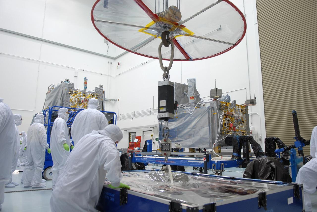
CAPE CANAVERAL, Fla. – At the Astrotech payload processing facility in Titusville, Fla., workers prepare to lift the SV1 and mate it to the SV2 spacecraft for the Space Tracking and Surveillance System – Demonstrators, or STSS Demo, Program. STSS-Demo is a space-based sensor component of a layered Ballistic Missile Defense System designed for the overall mission of detecting, tracking and discriminating ballistic missiles. The spacecraft is capable of tracking objects after boost phase and provides trajectory information to other sensors. It will be launched by NASA for the Missile Defense Agency between 8 and 8:58 a.m. EDT Sept. 18. Approved for Public Release 09-MDA-04886 (10 SEPT 09) Photo credit: NASA/Jim Grossmann
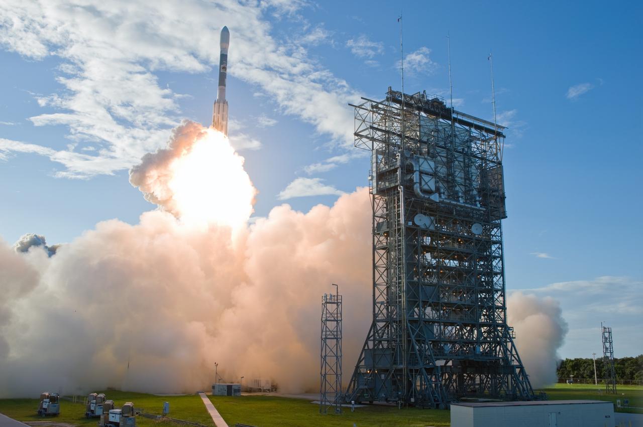
CAPE CANAVERAL, Fla. – The United Launch Alliance Delta II rocket carrying the Space Tracking and Surveillance System - Demonstrator, or STSS-Demo, spacecraft leaps into the sky from Launch Pad 17-B at Cape Canaveral Air Force Station. STSS-Demo was launched at 8:20:22 a.m. EDT by NASA for the U.S. Missile Defense Agency. The STSS-Demo is a space-based sensor component of a layered Ballistic Missile Defense System designed for the overall mission of detecting, tracking and discriminating ballistic missiles. STSS is capable of tracking objects after boost phase and provides trajectory information to other sensors. Photo credit: NASA/Sandra Joseph- Kevin O'Connell
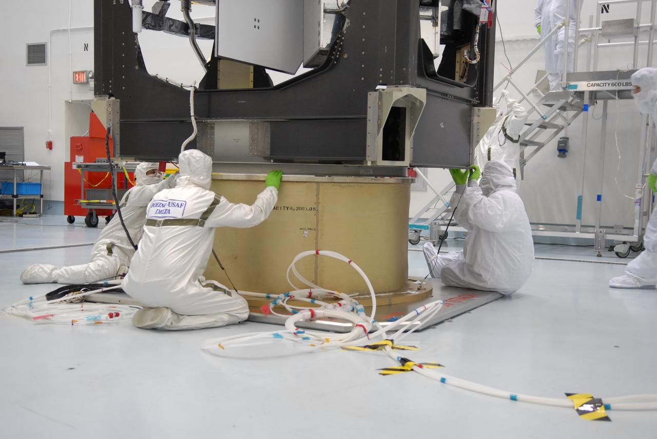
CAPE CANAVERAL, Fla. – At the Astrotech payload processing facility in Titusville, Fla., workers observe as the SV1-SV2 spacecraft is lifted for weighing. The two spacecraft are known as the Space Tracking and Surveillance System – Demonstrators, or STSS Demo, which is a space-based sensor component of a layered Ballistic Missile Defense System designed for the overall mission of detecting, tracking and discriminating ballistic missiles. STSS is capable of tracking objects after boost phase and provides trajectory information to other sensors. It will be launched by NASA for the Missile Defense Agency between 8 and 8:58 a.m. EDT Sept. 18. Approved for Public Release 09-MDA-04886 (10 SEPT 09) Photo credit: NASA/Jim Grossmann
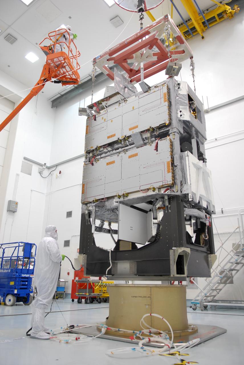
CAPE CANAVERAL, Fla. – At the Astrotech payload processing facility in Titusville, Fla., the SV1-SV2 spacecraft is lifted for weighing. The two spacecraft are known as the Space Tracking and Surveillance System – Demonstrators, or STSS Demo, which is a space-based sensor component of a layered Ballistic Missile Defense System designed for the overall mission of detecting, tracking and discriminating ballistic missiles. STSS is capable of tracking objects after boost phase and provides trajectory information to other sensors. It will be launched by NASA for the Missile Defense Agency between 8 and 8:58 a.m. EDT Sept. 18. Approved for Public Release 09-MDA-04886 (10 SEPT 09) Photo credit: NASA/Jim Grossmann
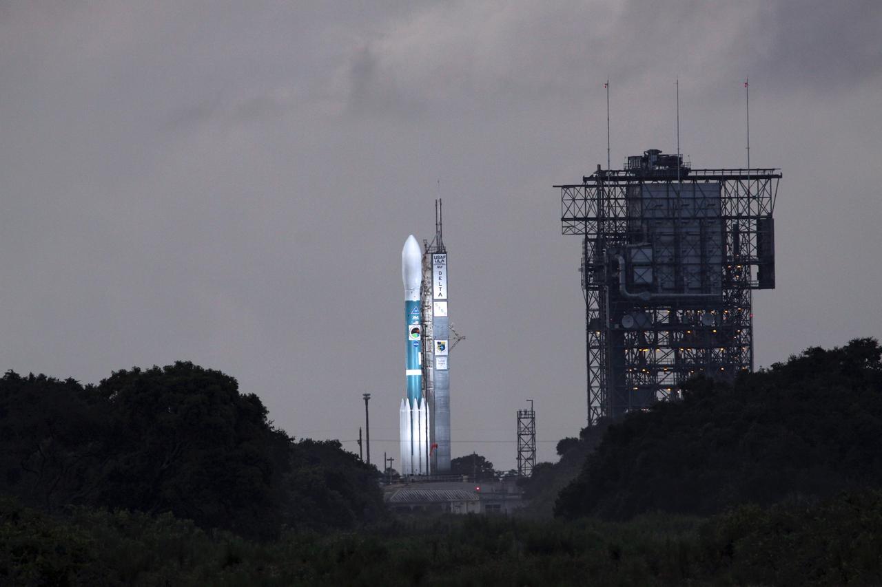
CAPE CANAVERAL, Fla. – On Launch Pad 17-B at Cape Canaveral Air Force Station in Florida, the Space Tracking and Surveillance System - Demonstrator spacecraft is bathed in light under a dark, cloudy sky. Rain over Central Florida's east coast caused the scrub of the launch. STSS Demo is a space-based sensor component of a layered Ballistic Missile Defense System designed for the overall mission of detection, tracking and discriminating ballistic missiles. STSS is capable of tracking objects after boost phase and provides trajectory information to other sensors. It will be launched by NASA for the Missile Defense Agency between 8 and 8:58 a.m. EDT Sept. 24. Photo credit: NASA/Jack Pfaller
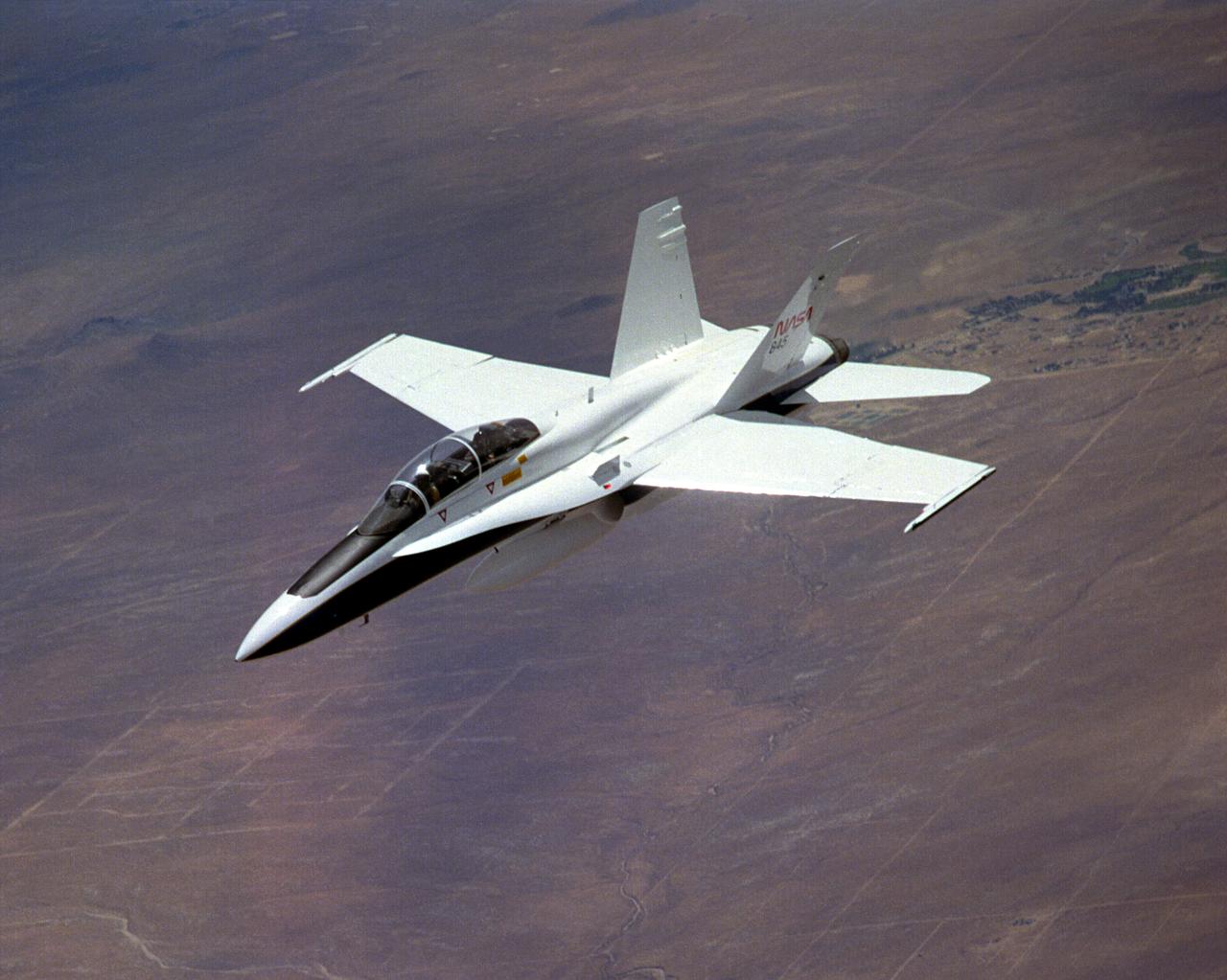
The National Aeronautics and Space Administration's Systems Research Aircraft (SRA), a highly modified F-18 jet fighter, during a research flight. The former Navy aircraft was flown by NASA's Dryden Flight Research Center at Edwards Air Force Base, California, to evaluate a number of experimental aerospace technologies in a multi-year, joint NASA/DOD/industry program. Among the more than 20 experiments flight-tested were several involving fiber optic sensor systems. Experiments developed by McDonnell-Douglas and Lockheed-Martin centered on installation and maintenace techniques for various types of fiber-optic hardware proposed for use in military and commercial aircraft, while a Parker-Hannifin experiment focused in alternative fiber-optic designs for position measurement sensors as well as operational experience in handling optical sensor systems. Other experiments flown on this testbed aircraft included electronically-controlled control surface actuators, flush air data collection systems, "smart" skin antennae and laser-based systems. Incorporation of one or more of these technologies in future aircraft and spacecraft could result in signifigant savings in weight, maintenance and overall cost.
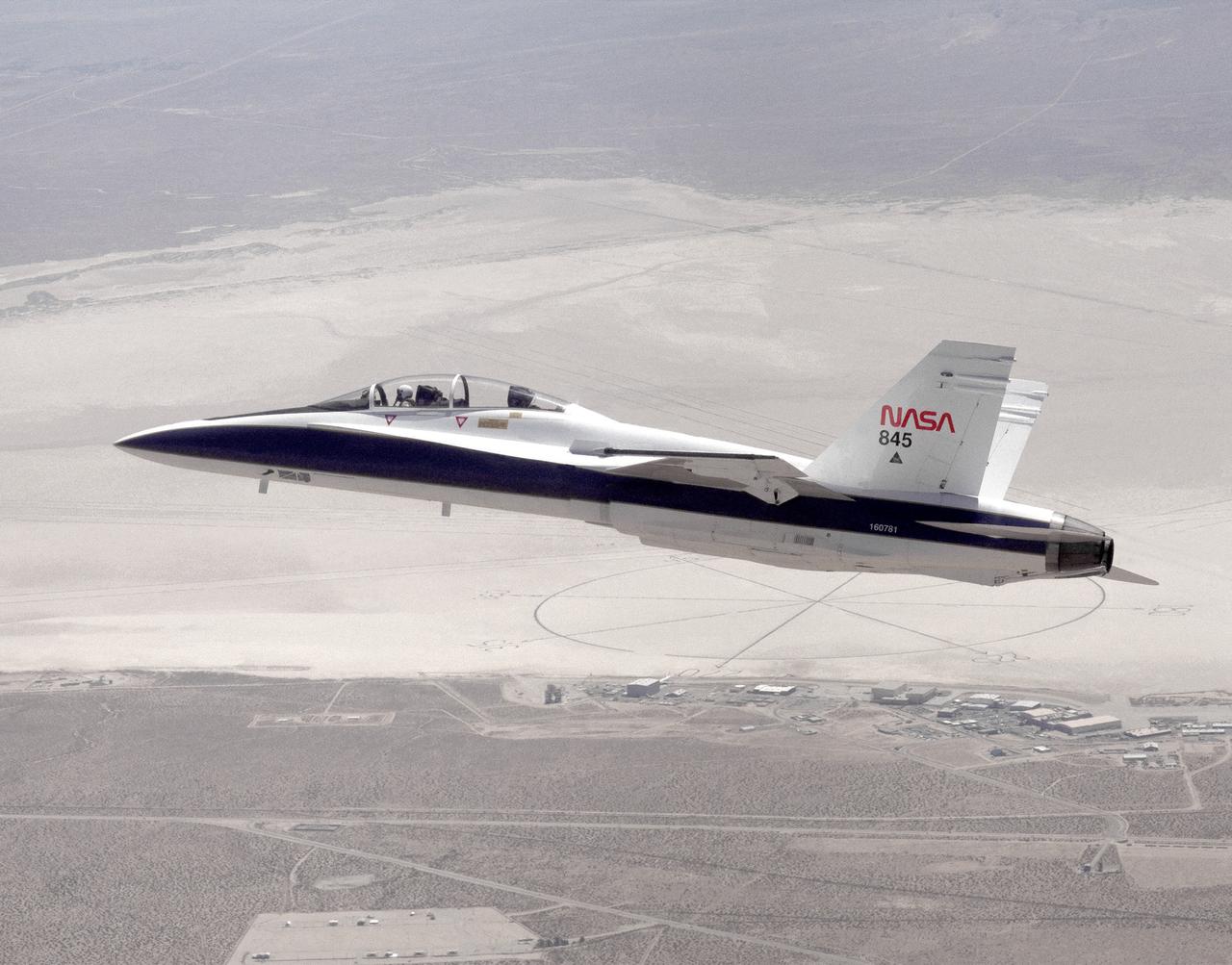
The National Aeronautics and Space Administration's Systems Research Aircraft (SRA), a highly modified F-18 jet fighter, on an early research flight over Rogers Dry Lake. The former Navy aircraft was flown by NASA's Dryden Flight Research Center at Edwards Air Force Base, California, to evaluate a number of experimental aerospace technologies in a multi-year, joint NASA/DOD/industry program. Among the more than 20 experiments flight-tested were several involving fiber optic sensor systems. Experiments developed by McDonnell-Douglas and Lockheed-Martin centered on installation and maintenace techniques for various types of fiber-optic hardware proposed for use in military and commercial aircraft, while a Parker-Hannifin experiment focused on alternative fiber-optic designs for postion measurement sensors as well as operational experience in handling optical sensor systems. Other experiments flown on this testbed aircraft included electronically-controlled control surface actuators, flush air data collection systems, "smart" skin antennae and laser-based systems. Incorporation of one or more of these technologies in future aircraft and spacecraft could result in signifigant savings in weight, maintenance and overall cost.
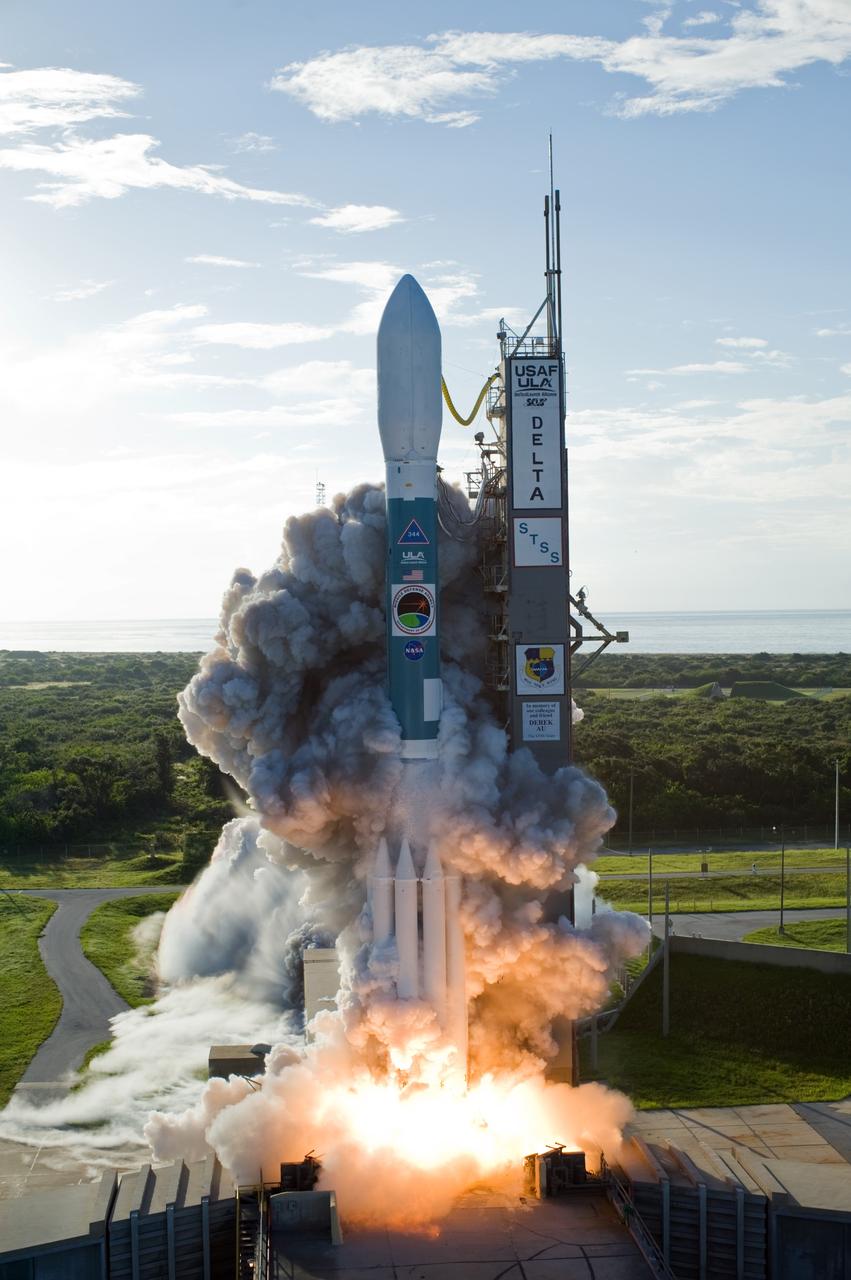
CAPE CANAVERAL, Fla. – Smoke billows around the United Launch Alliance Delta II rocket as it launches into space carrying the Space Tracking and Surveillance System - Demonstrator, or STSS-Demo, spacecraft. STSS-Demo was launched at 8:20:22 a.m. EDT by NASA for the U.S. Missile Defense Agency. The STSS-Demo is a space-based sensor component of a layered Ballistic Missile Defense System designed for the overall mission of detecting, tracking and discriminating ballistic missiles. Photo credit: NASA/Regina Mitchell-Tom Farrar

A test unit, or prototype, of NASA's Advanced Plant Habitat (APH) was delivered to the Space Station Processing Facility at the agency's Kennedy Space Center in Florida. The APH is the largest plant chamber built for the agency. Oscar Monje, a scientist on the Engineering Services Contract, prepares the base of the APH for engineering development tests to see how the science will integrate with the various systems of the plant habitat. The APH will have about 180 sensors and fourt times the light output of Veggie. The APH will be delivered to the International Space Station in March 2017.

A test unit, or prototype, of NASA's Advanced Plant Habitat (APH) was delivered to the Space Station Processing Facility at the agency's Kennedy Space Center in Florida. The APH is the largest plant chamber built for the agency. The base of the APH is being prepared for engineering development tests to see how the science will integrate with the various systems of the plant habitat. It will have 180 sensors and four times the light output of Veggie. The APH will be delivered to the International Space Station in March 2017.
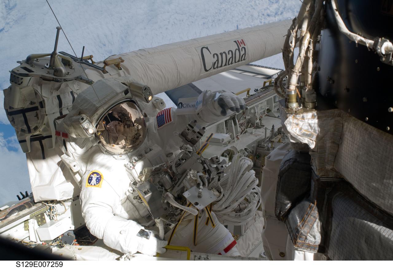
S129-E-007259 (21 Nov. 2009) --- Astronaut Randy Bresnik, STS-129 mission specialist, is pictured near the base of the Orbiter Boom Sensor System on the starboard side of the cargo bay of the space shuttle Atlantis, docked with the International Space Station. Astronauts Bresnik and Mike Foreman were in the midst of the second of three scheduled spacewalks for this shuttle crew, working in cooperation with the five current crewmembers for the orbital outpost and with their five Atlantis crewmates, all of whom pitched in EVA support from inside.
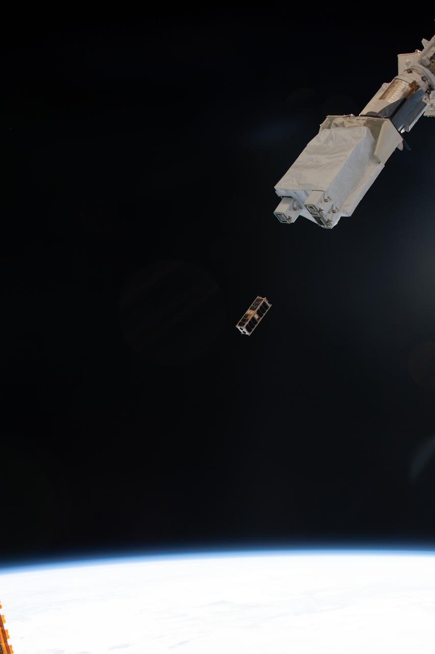
iss061e052148 (11/20/2019) --- An external view of the deployment of the RWASAT-1 CubeSat from the JEM Small Satellite Orbital Deployer aboard the International Space Station (ISS). RWanda Satellite-1 (RWASAT-1) is the first Rwandan 3-Unit (3U) CubeSat is built under a partnership of the Rwanda Utilities Regulatory Authority (RURA) and Tokyo University, to help develop a space engineering capacity in Rwanda. RWASAT-1 has two cameras for monitoring the status of agriculture, and a receiver for data collection from ground based sensors.
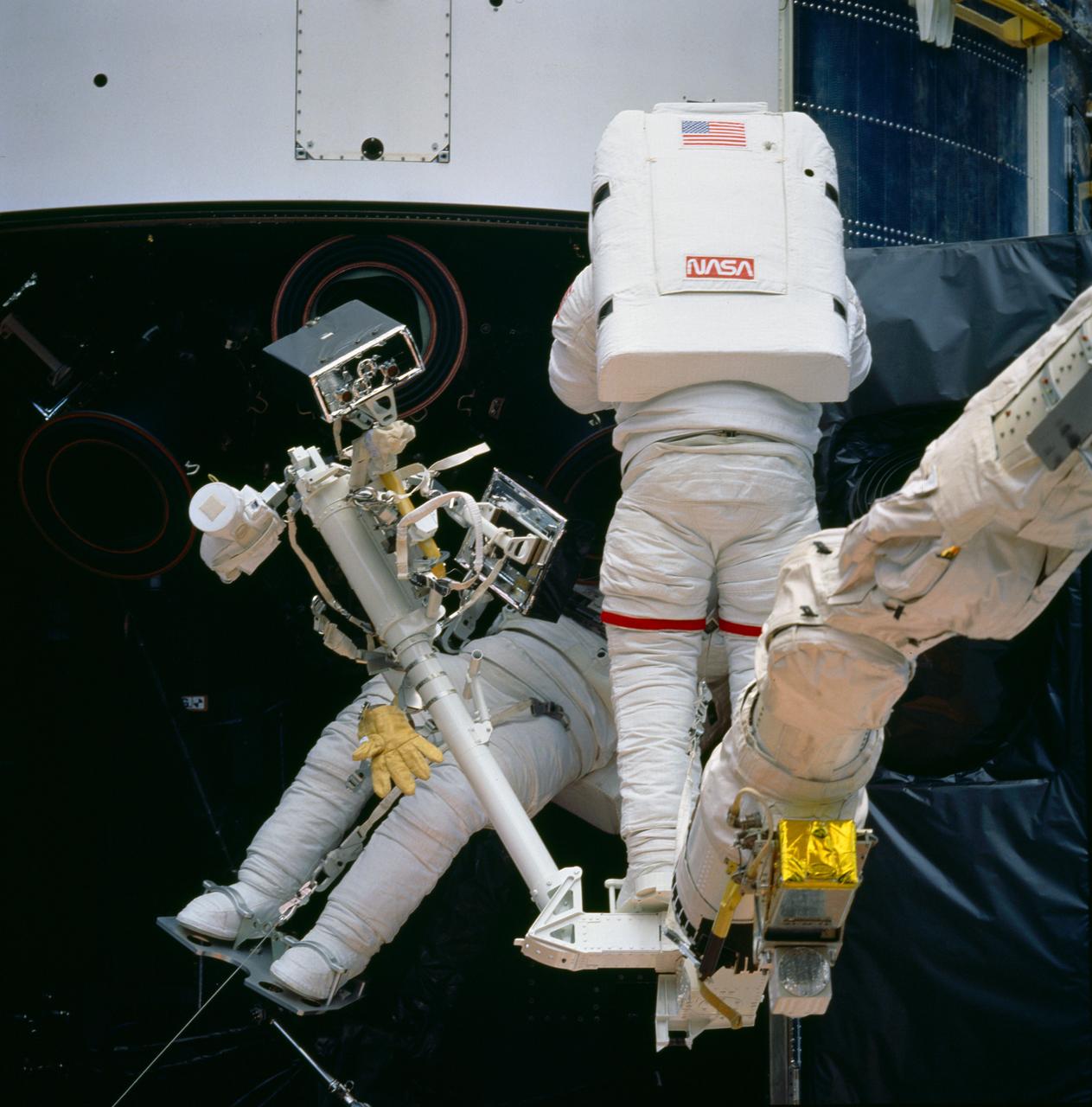
STS061-87-046 (5 Dec 1993) --- Astronauts Jeffrey A. Hoffman (right) and F. Story Musgrave work near the base of the Hubble Space Telescope (HST) on the first of five spacewalks. Their particular mission here is to replace failed Rate Sensor Units (RSU) inside the telescope's housing. Hoffman is anchored to a foot restraint, mounted on the end of the Space Shuttle Endeavour's Remote Manipulator System (RMS) arm, while Musgrave is standing on a foot restraint attached to a support structure in the cargo bay.
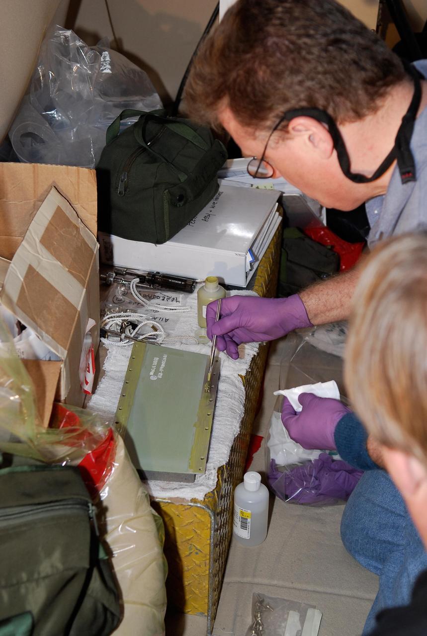
KENNEDY SPACE CENTER, FLA. -- On Launch Pad 39A at NASA's Kennedy Space Center, technicians prepare the cover to be installed over the engine cutoff, or ECO, sensor system connector and wiring on space shuttle space shuttle Atlantis' external tank. The feed-through connector passes the wires from the inside of the tank to the outside. Results of a tanking test on Dec. 18 pointed to an open circuit in the feed-through connector wiring, which is located at the base of the tank. The pins in the replacement connector were precisely soldered to create a connection that allows sensors inside the tank to send signals to the computers onboard Atlantis. The launch date for the shuttle's STS-122 mission has now been targeted for Feb. 7. Photo credit: NASA/Kim Shiflett
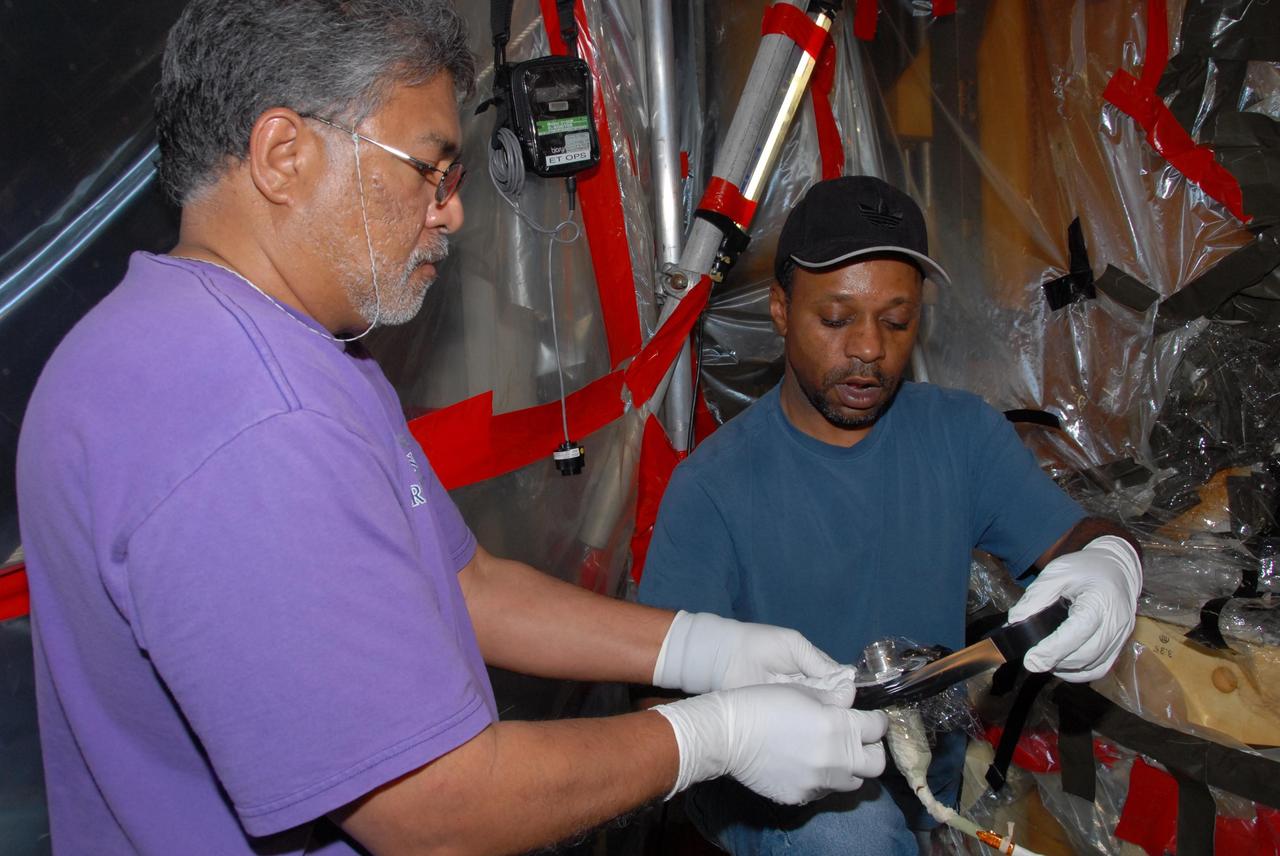
KENNEDY SPACE CENTER, FLA. -- At Launch Pad 39A, a team of external tank specialists from Lockheed Martin and the United Space Alliance undertakes the task of removing the hydrogen feed-through connector in support of space shuttle Atlantis' STS-122 mission. Here, technicians wrap the connector for transport to NASA's Marshall Space Flight Center in Huntsville, Ala., for further cryogenic testing. Some of the tank's engine cutoff sensors, or ECO sensors, failed during propellant tanking for launch attempts on Dec. 6 and Dec. 9. Results of a tanking test on Dec. 18 pointed to an open circuit in the feed-through connector wiring, which is located at the base of the tank. The feed-through connector passes the wires from the inside of the tank to the outside. After the data from additional testing on the connector is analyzed, shuttle program managers will decide on a forward plan. Launch of STS-122 is targeted for January 2008. Photo credit: NASA/George Shelton

KENNEDY SPACE CENTER, FLA. -- At Launch Pad 39A, a team of external tank specialists from Lockheed Martin and the United Space Alliance undertakes the task of removing the hydrogen feed-through connector in support of space shuttle Atlantis' STS-122 mission. Here, technicians wrap the connector for transport to NASA's Marshall Space Flight Center in Huntsville, Ala., for further cryogenic testing. Some of the tank's engine cutoff sensors, or ECO sensors, failed during propellant tanking for launch attempts on Dec. 6 and Dec. 9. Results of a tanking test on Dec. 18 pointed to an open circuit in the feed-through connector wiring, which is located at the base of the tank. The feed-through connector passes the wires from the inside of the tank to the outside. After the data from additional testing on the connector is analyzed, shuttle program managers will decide on a forward plan. Launch of STS-122 is targeted for January 2008. Photo credit: NASA/George Shelton
KENNEDY SPACE CENTER, FLA. -- On Launch Pad 39A at NASA's Kennedy Space Center, a technician begins attaching the cover over the engine cutoff, or ECO, sensor system connector and wiring on space shuttle Atlantis' external tank. The feed-through connector passes the wires from the inside of the tank to the outside. Results of a tanking test on Dec. 18 pointed to an open circuit in the feed-through connector wiring, which is located at the base of the tank. The pins in the replacement connector were precisely soldered to create a connection that allows sensors inside the tank to send signals to the computers onboard Atlantis. The launch date for the shuttle's STS-122 mission has now been targeted for Feb. 7. Photo credit: NASA/Kim Shiflett
KENNEDY SPACE CENTER, FLA. -- On Launch Pad 39A at NASA's Kennedy Space Center, technicians prepare the cover to be installed over the engine cutoff, or ECO, sensor system connector and wiring on space shuttle Atlantis' external tank. The feed-through connector passes the wires from the inside of the tank to the outside. Results of a tanking test on Dec. 18 pointed to an open circuit in the feed-through connector wiring, which is located at the base of the tank. The pins in the replacement connector were precisely soldered to create a connection that allows sensors inside the tank to send signals to the computers onboard Atlantis. The launch date for the shuttle's STS-122 mission has now been targeted for Feb. 7. Photo credit: NASA/Kim Shiflett
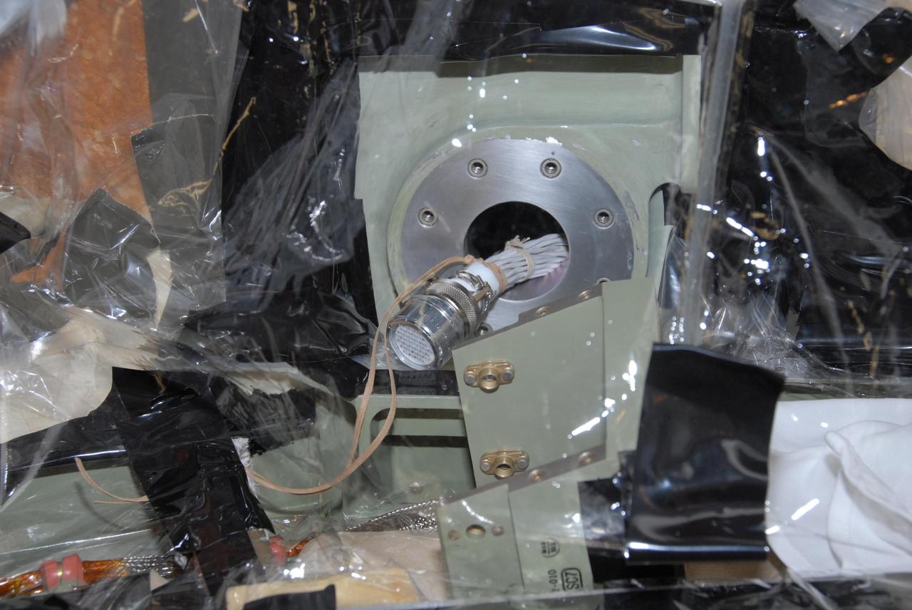
KENNEDY SPACE CENTER, FLA. -- This closeup shows the internal connector to which the replacement feed-through connector in the engine cutoff, or ECO, sensor system on space shuttle Atlantis' external tank will be installed. The feed-through connector passes the wires from the inside of the tank to the outside. Results of a tanking test on Dec. 18 pointed to an open circuit in the feed-through connector wiring, which is located at the base of the tank. The pins in the replacement connector have been precisely soldered to create a connection that allows sensors inside the tank to send signals to the computers onboard Atlantis. The work is being done on Launch Pad 39A. Space shuttle Atlantis is now targeted for launch on Feb. 7. Photo credit: NASA/George Shelton
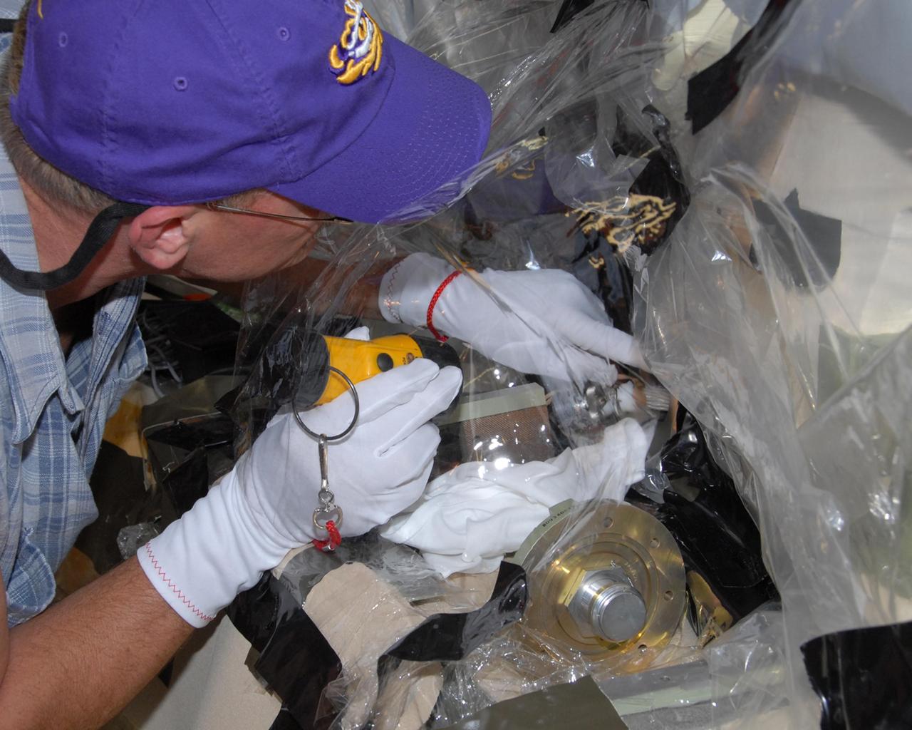
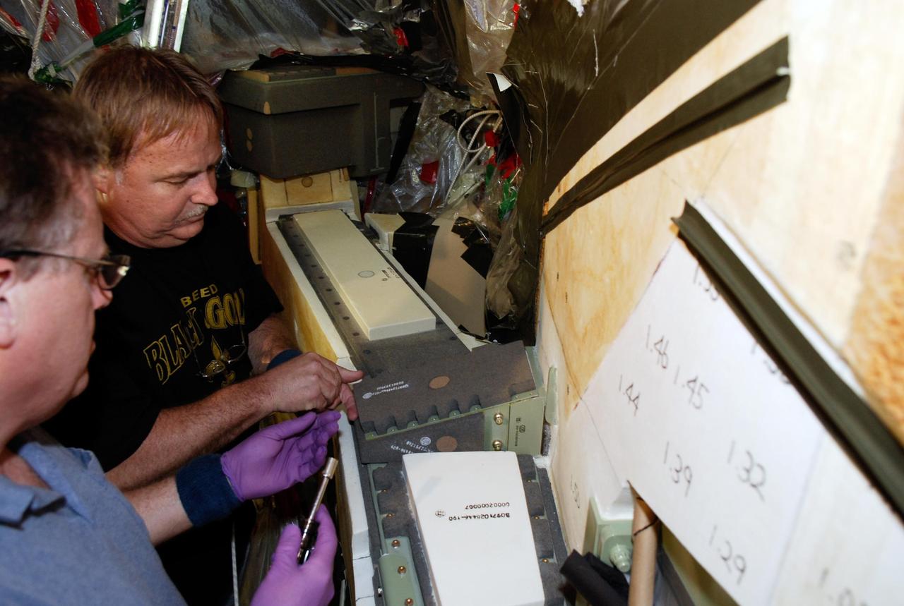
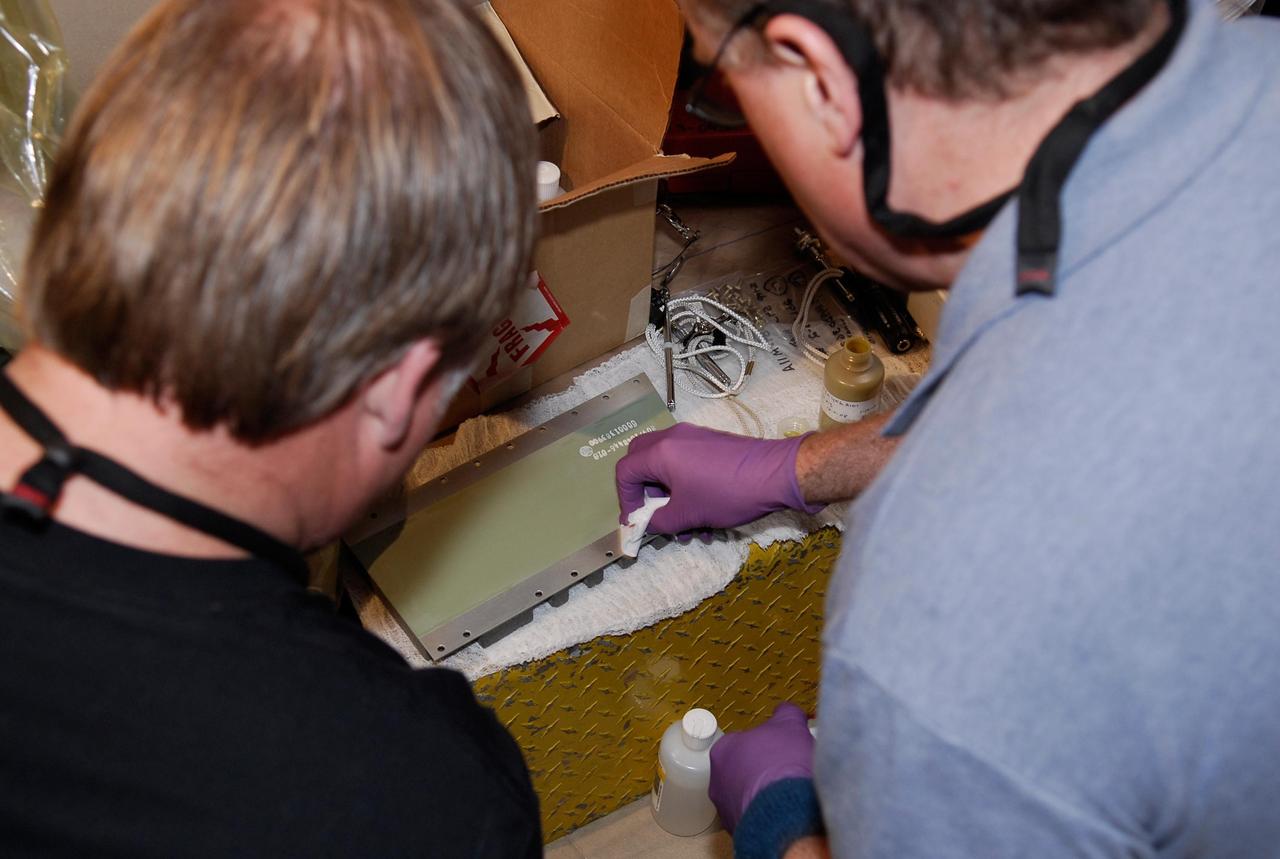
KENNEDY SPACE CENTER, FLA. -- Mike Berger, with Lockheed Martin, examines the internal connector on space shuttle Atlantis' external tank to which the replacement feed-through connector in the engine cutoff, or ECO, sensor system will be attached. The replacement connector is seen below Berger's hand. The feed-through connector passes the wires from the inside of the tank to the outside. Results of a tanking test on Dec. 18 pointed to an open circuit in the feed-through connector wiring, which is located at the base of the tank. The pins in the replacement connector have been precisely soldered to create a connection that allows sensors inside the tank to send signals to the computers onboard Atlantis. The work is being done on Launch Pad 39A. Space shuttle Atlantis is now targeted for launch on Feb. 7. Photo credit: NASA/George Shelton
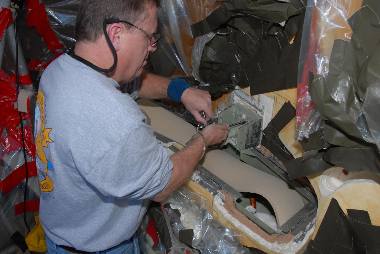
KENNEDY SPACE CENTER, FLA. -- At Launch Pad 39A, a team of external tank specialists from Lockheed Martin and the United Space Alliance undertakes the task of removing the hydrogen feed-through connector in support of space shuttle Atlantis' STS-122 mission. Here, a technician removes a pair of support brackets. Some of the tank's engine cutoff sensors, or ECO sensors, failed during propellant tanking for launch attempts on Dec. 6 and Dec. 9. Results of a tanking test on Dec. 18 pointed to an open circuit in the feed-through connector wiring, which is located at the base of the tank. The feed-through connector passes the wires from the inside of the tank to the outside. After the data from additional testing on the connector is analyzed, shuttle program managers will decide on a forward plan. Launch of STS-122 is targeted for January 2008. Photo credit: NASA/George Shelton
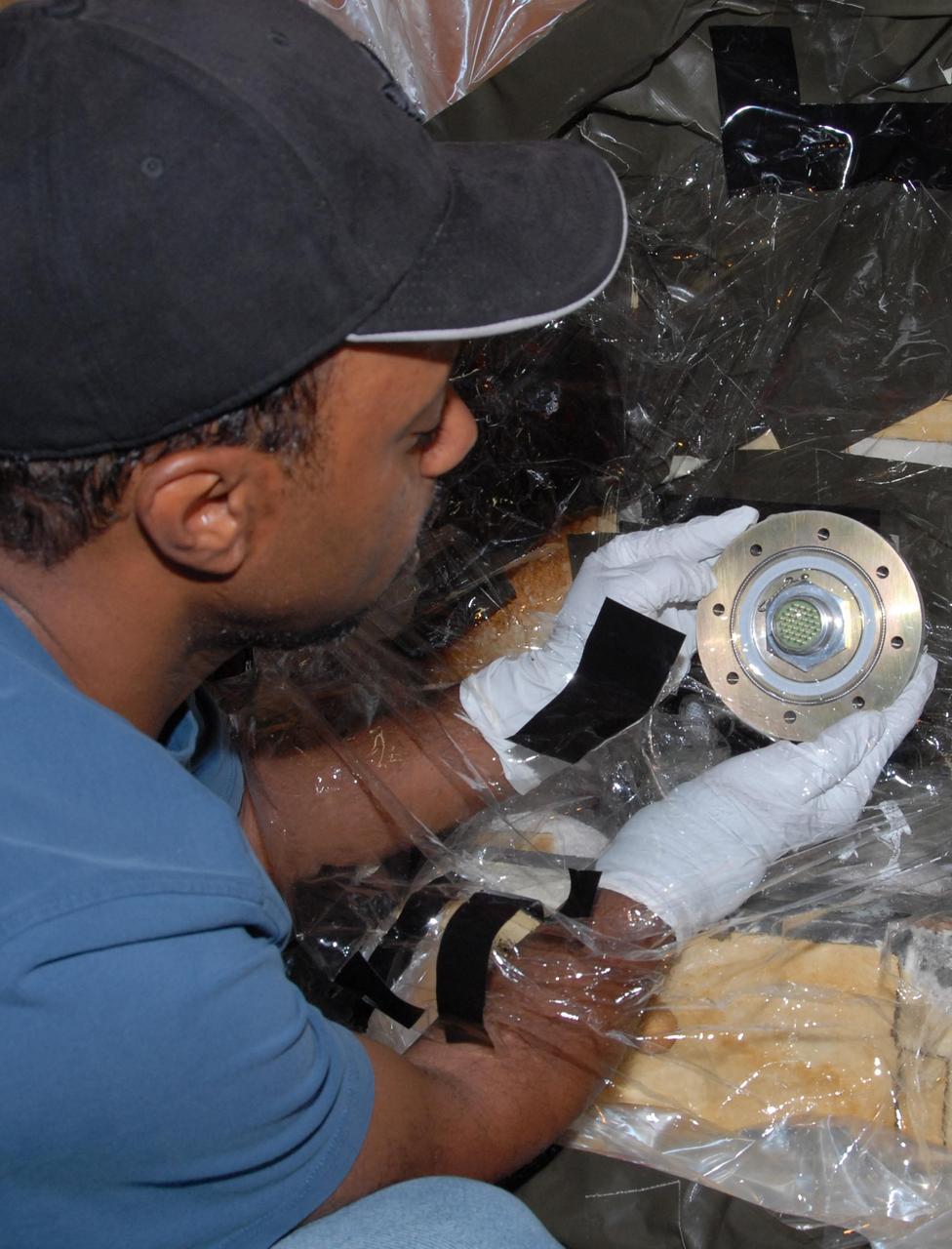
KENNEDY SPACE CENTER, FLA. -- At Launch Pad 39A, a team of external tank specialists from Lockheed Martin and the United Space Alliance undertakes the task of removing the hydrogen feed-through connector in support of space shuttle Atlantis' STS-122 mission. Here, a technician inspects the connector just removed from the external tank. Some of the tank's engine cutoff sensors, or ECO sensors, failed during propellant tanking for launch attempts on Dec. 6 and Dec. 9. Results of a tanking test on Dec. 18 pointed to an open circuit in the feed-through connector wiring, which is located at the base of the tank. The feed-through connector passes the wires from the inside of the tank to the outside. After the data from additional testing on the connector is analyzed, shuttle program managers will decide on a forward plan. Launch of STS-122 is targeted for January 2008. Photo credit: NASA/George Shelton
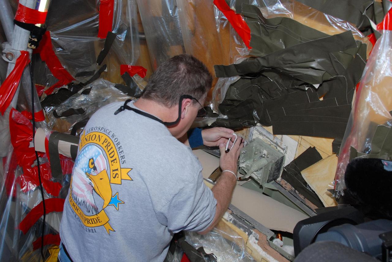
KENNEDY SPACE CENTER, FLA. -- At Launch Pad 39A, a team of external tank specialists from Lockheed Martin and the United Space Alliance undertakes the task of removing the hydrogen feed-through connector in support of space shuttle Atlantis' STS-122 mission. Here, a technician cuts the external connector cable. Some of the tank's engine cutoff sensors, or ECO sensors, failed during propellant tanking for launch attempts on Dec. 6 and Dec. 9. Results of a tanking test on Dec. 18 pointed to an open circuit in the feed-through connector wiring, which is located at the base of the tank. The feed-through connector passes the wires from the inside of the tank to the outside. After the data from additional testing on the connector is analyzed, shuttle program managers will decide on a forward plan. Launch of STS-122 is targeted for January 2008. Photo credit: NASA/George Shelton
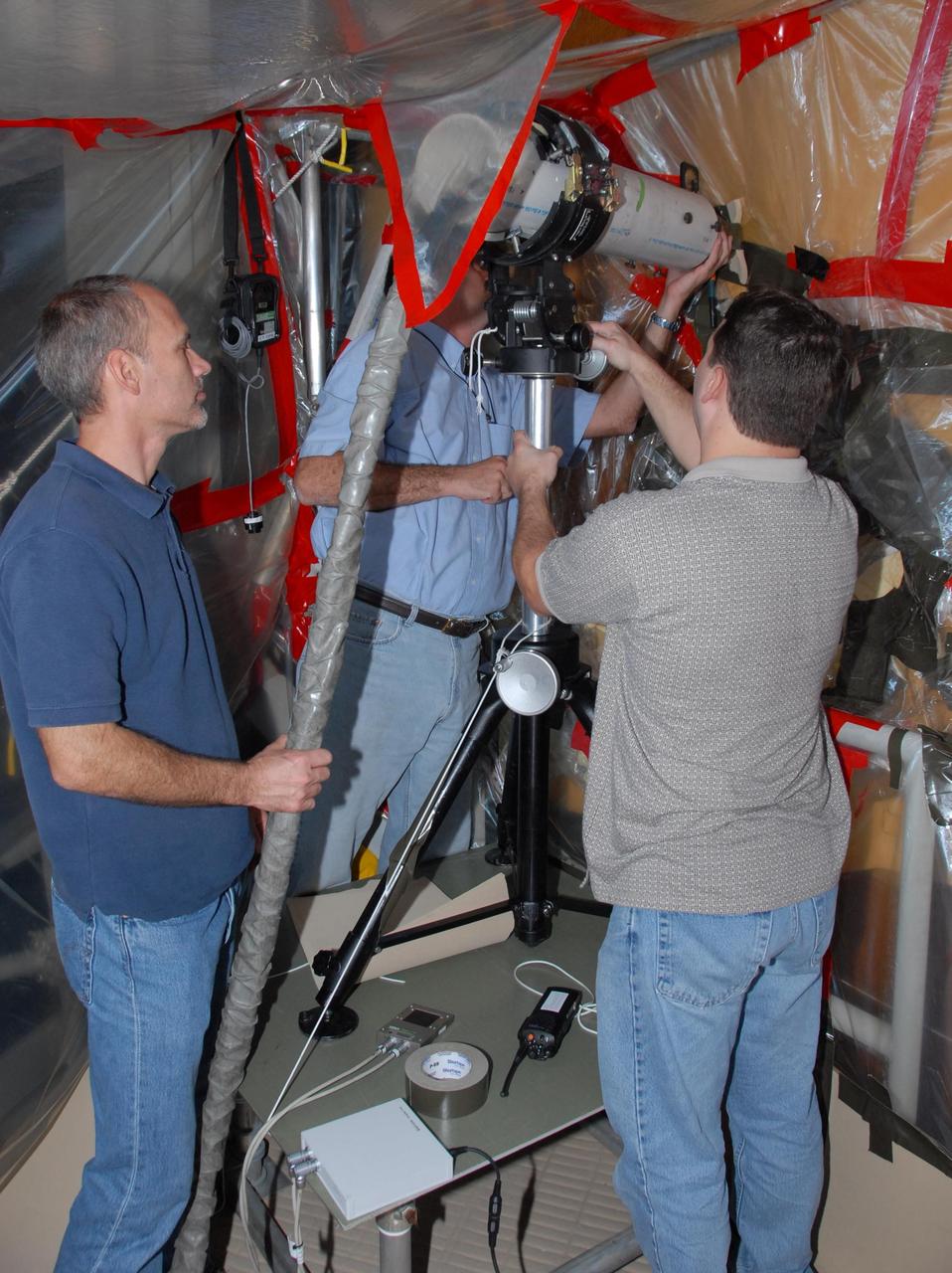
KENNEDY SPACE CENTER, FLA. -- At Launch Pad 39A, a team of external tank specialists from Lockheed Martin and the United Space Alliance undertakes the task of removing the hydrogen feed-through connector in support of space shuttle Atlantis' STS-122 mission. Here, technicians set up equipment that will be used to take X-rays of the connector cable. Some of the tank's engine cutoff sensors, or ECO sensors, failed during propellant tanking for launch attempts on Dec. 6 and Dec. 9. Results of a tanking test on Dec. 18 pointed to an open circuit in the feed-through connector wiring, which is located at the base of the tank. The feed-through connector passes the wires from the inside of the tank to the outside. After the data from additional testing on the connector is analyzed, shuttle program managers will decide on a forward plan. Launch of STS-122 is targeted for January 2008. Photo credit: NASA/George Shelton
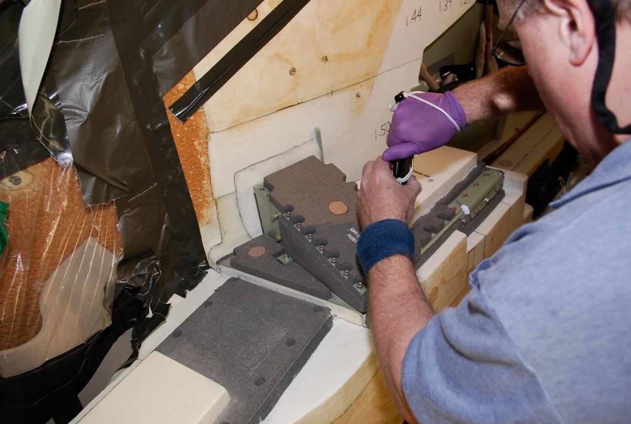
KENNEDY SPACE CENTER, FLA. -- On Launch Pad 39A at NASA's Kennedy Space Center, a technician completes installing the cover over the engine cutoff, or ECO, sensor system connector and wiring on space shuttle Atlantis' external tank. The feed-through connector passes the wires from the inside of the tank to the outside. Results of a tanking test on Dec. 18 pointed to an open circuit in the feed-through connector wiring, which is located at the base of the tank. The pins in the replacement connector were precisely soldered to create a connection that allows sensors inside the tank to send signals to the computers onboard Atlantis. The launch date for the shuttle's STS-122 mission has now been targeted for Feb. 7. Photo credit: NASA/Kim Shiflett
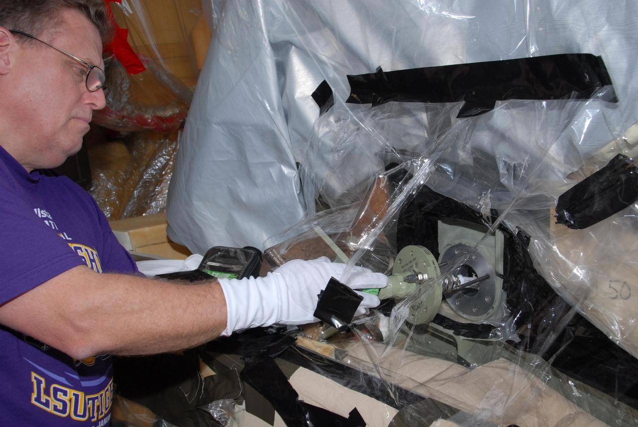
KENNEDY SPACE CENTER, FLA. -- Lloyd Johns, with Lockheed Martin, attaches the replacement feed-through connector in the engine cutoff, or ECO, sensor system to the internal connector on space shuttle Atlantis' external tank. The feed-through connector passes the wires from the inside of the tank to the outside. Results of a tanking test on Dec. 18 pointed to an open circuit in the feed-through connector wiring, which is located at the base of the tank. The pins in the replacement connector have been precisely soldered to create a connection that allows sensors inside the tank to send signals to the computers onboard Atlantis. The work is being done on Launch Pad 39A. Space shuttle Atlantis is now targeted for launch on Feb. 7. Photo credit: NASA/George Shelton
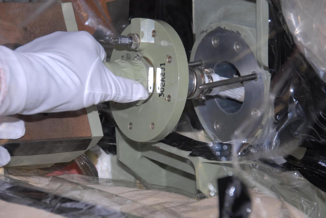
KENNEDY SPACE CENTER, FLA. -- Lloyd Johns, with Lockheed Martin, attaches the replacement feed-through connector in the engine cutoff, or ECO, sensor system to the internal connector on space shuttle Atlantis' external tank. The feed-through connector passes the wires from the inside of the tank to the outside. Results of a tanking test on Dec. 18 pointed to an open circuit in the feed-through connector wiring, which is located at the base of the tank. The pins in the replacement connector have been precisely soldered to create a connection that allows sensors inside the tank to send signals to the computers onboard Atlantis. The work is being done on Launch Pad 39A. Space shuttle Atlantis is now targeted for launch on Feb. 7. Photo credit: NASA/George Shelton
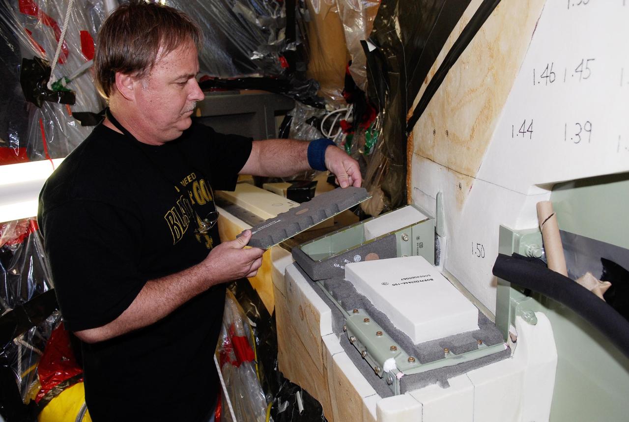
KENNEDY SPACE CENTER, FLA. -- On Launch Pad 39A at NASA's Kennedy Space Center, a technician gets ready to place the cover over the engine cutoff, or ECO, sensor system connector and wiring on space shuttle Atlantis' external tank. The feed-through connector passes the wires from the inside of the tank to the outside. Results of a tanking test on Dec. 18 pointed to an open circuit in the feed-through connector wiring, which is located at the base of the tank. The pins in the replacement connector were precisely soldered to create a connection that allows sensors inside the tank to send signals to the computers onboard Atlantis. The launch date for the shuttle's STS-122 mission has now been targeted for Feb. 7. Photo credit: NASA/Kim Shiflett
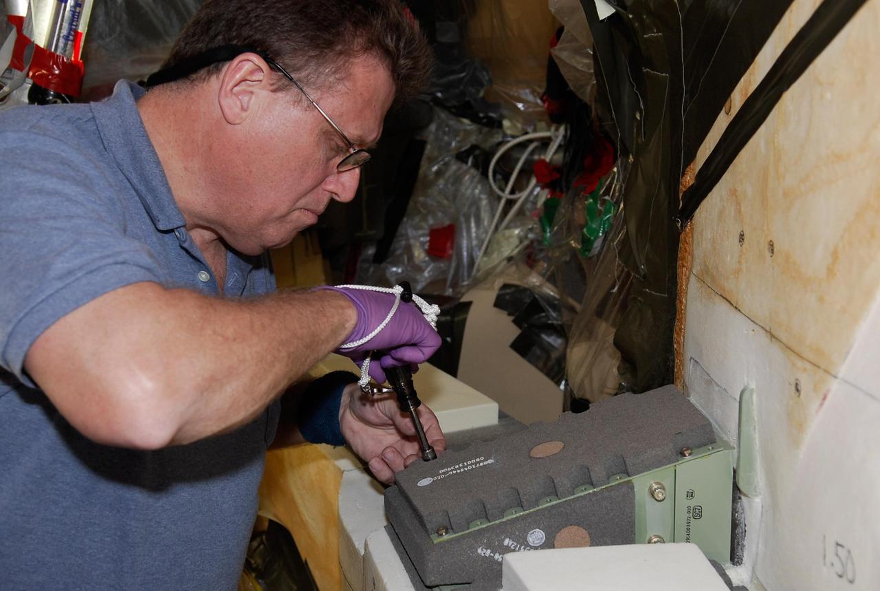
KENNEDY SPACE CENTER, FLA. -- On Launch Pad 39A at NASA's Kennedy Space Center, a technician attaches the cover over the engine cutoff, or ECO, sensor system connector and wiring on space shuttle Atlantis' external tank. The feed-through connector passes the wires from the inside of the tank to the outside. Results of a tanking test on Dec. 18 pointed to an open circuit in the feed-through connector wiring, which is located at the base of the tank. The pins in the replacement connector were precisely soldered to create a connection that allows sensors inside the tank to send signals to the computers onboard Atlantis. The launch date for the shuttle's STS-122 mission has now been targeted for Feb. 7. Photo credit: NASA/Kim Shiflett