
FDCD Branch Stability and Control branch: Names, rows front to back, people left to right: Ground level: 1. ?? 2. Debra L. Livingston 3. Katherine G. Johnson 4. Robert Dunning Step 1: 1. Ellie Fillmore (?) 2. Al Hamer 3. Suresh Joshi Step 2: 1. John Young 2. Ernest Armstrong 3. Vladislav Klein 4. Charles T. Woolley Step 3: 1. Lawrence Taylor 2. Tony Fontana Step 4: 1. Bill Suit 2. Jane Carpenter 3. Daniel P. Giesy 4. Mario Smith Step 5: 1. Albert Schy 2. Ray Montgomery 3. Sahajendra Singh Top level: 1: Jim Batterson 2. Jim Williams 3. Claude Keckler 4. N. Sundararajan Behind all: John Shebalin Names given by Danial P. Giesy

Stability and Control Branch Photo: Names, rows front to back, people left to right: Row 1: 1. ?? Graduate Student (USAF) 2. Robert Dunning 3. Rhonda Harvey Poppen 4. Katherine G. Johnson 5. ?? Graduate Student (USAF) 6. Vladislav Klein Row 2: 1. Mario Smith 2. Jeff Williams 3. N. Sundararajan 4. Tony Fontana 5. John Young Row 3: 1. Lawrence Taylor 2. Jim Batterson 3. Suresh Joshi 4. Daniel P. Giesy Row 4: 1. Bill Suit 2. Albert A. Schy 3. Al Hamer 4. Ernest Armstrong 5. Claude Keckler Row 5: 1. Chris Brown 2. Robert Bullock 3. Ray Montgomery 4. Jim Williams 5. Sahajendra Singh 6. Graduate Student (Egypt) Names given by Daniel P. Giesy.

Event: Horizontal Stabilator Install The Low Boom Flight Demonstrator manufacturing team installed the horizontal stabilizers to the aircraft. These are used along with the flight control computers to keep the airplane flying safely and providing the pitch control so that the pilot can fly the missions envisioned for the X-59

Event: Horizontal Stabilator Install The Low Boom Flight Demonstrator manufacturing team installed the horizontal stabilizers to the aircraft. These are used along with the flight control computers to keep the airplane flying safely and providing the pitch control so that the pilot can fly the missions envisioned for the X-59.

Event: Horizontal Stabilator Install The Low Boom Flight Demonstrator manufacturing team installed the horizontal stabilizers to the aircraft. These are used along with the flight control computers to keep the airplane flying safely and providing the pitch control so that the pilot can fly the missions envisioned for the X-59.

Event: Horizontal Stabilator Install The Low Boom Flight Demonstrator manufacturing team installed the horizontal stabilizers to the aircraft. These are used along with the flight control computers to keep the airplane flying safely and providing the pitch control so that the pilot can fly the missions envisioned for the X-59.
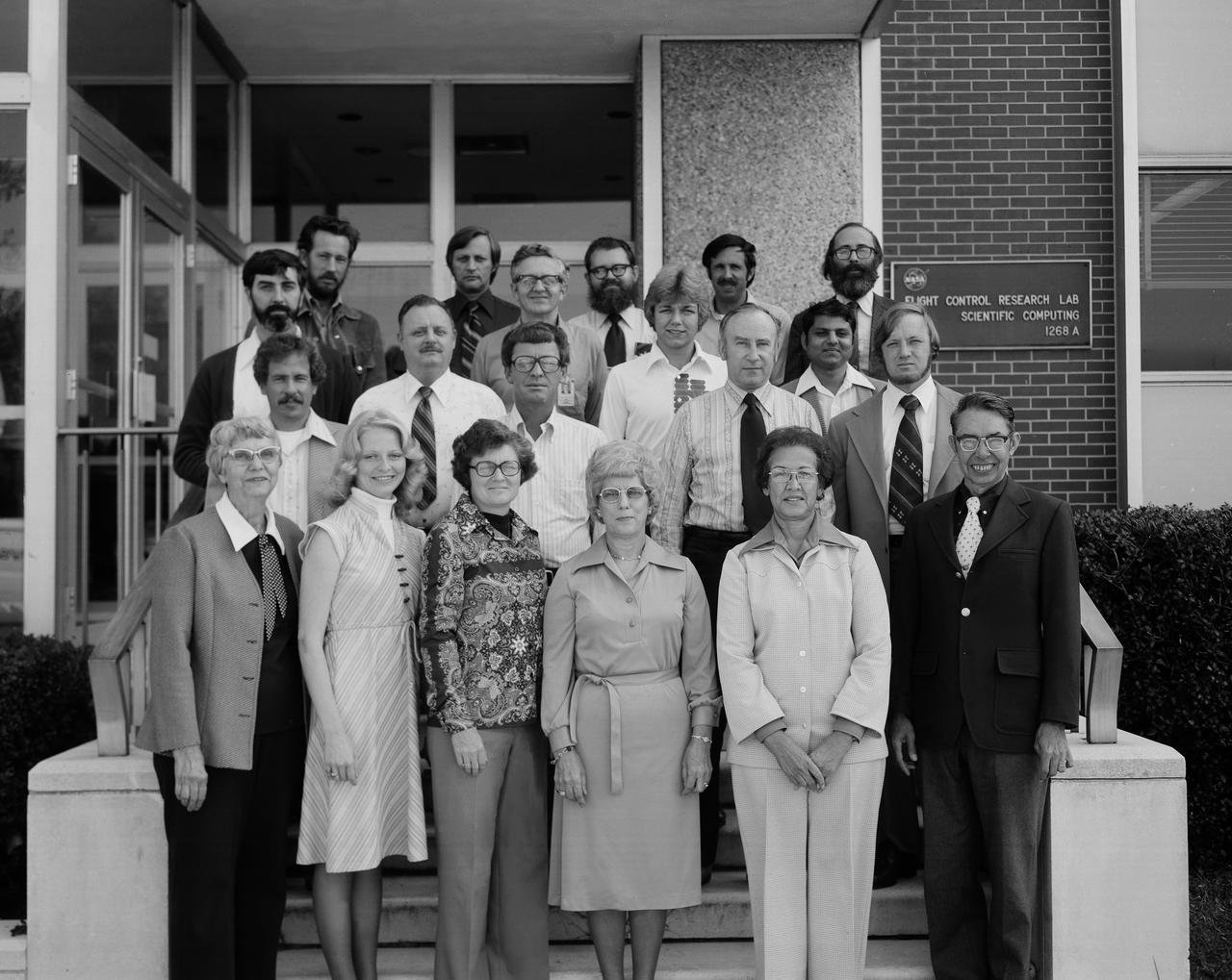
FDCD Stability and Control Branch Photo. Names, rows front to back, people left to right: Ground level: 1. Margery Hanna 2. Debra L. Livingston 3. Carolyn Grantham 4. Nell Moore 5. Katherine G. Johnson 6. Hewitt Phillips Step 1: 1. John Shaughnessy 2. John Young 3. Bill Martz 4. Charles T. Woolley Step 2: 1. Al Hamer 2. Marion Wise (?) 3. Suresh Joshi Step 3: 1. Willard W. Anderson 2. Albert A. Schy 3. Daniel P. Giesy Step 4: 1. Hugh Bergeron 2. Claude Keckler 3. Nelson Groom 4. Ralph Will Names Given by Danial Pl. Giesy.
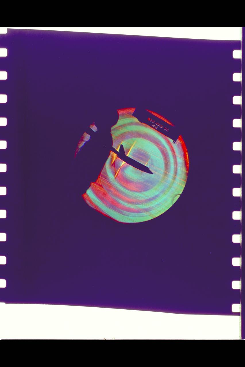
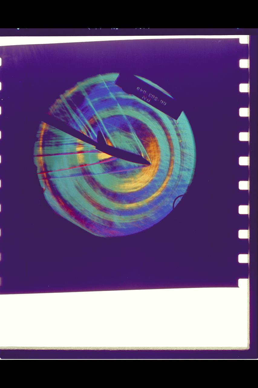
MSC Space Shuttle Stability and Control Characteristics. Schlieren of North American Rockwell Straight Wing orbiter approximate Mach .95
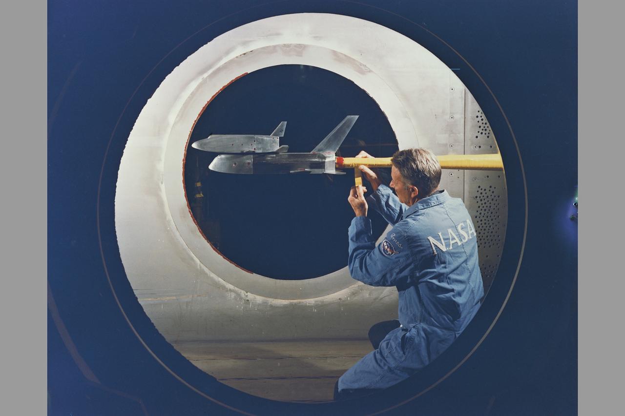
MSC Space Shuttle Model stability and control characteristics test in 9x7ft w.t. (test number not available)
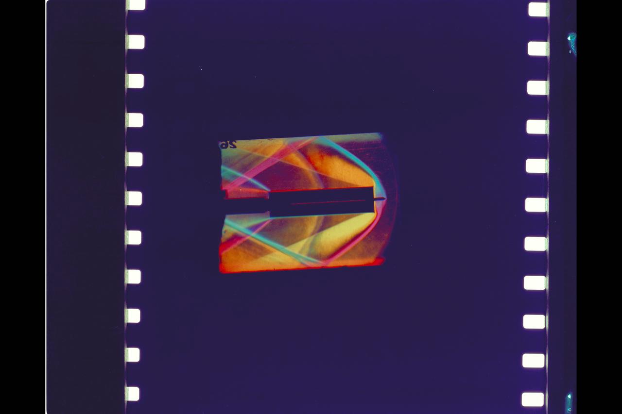
MSC Space Shuttle Stability and Control Characteristics. Schlieren of a Hollow Tube in 6ft. W.T. Test-66-503 Approximate Mach 1.2
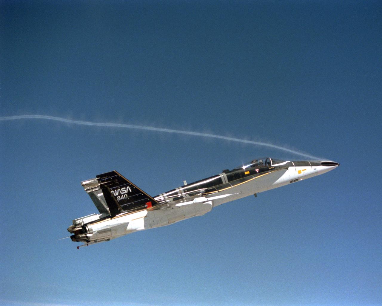
During the final phase of tests with the HARV, Dryden technicians installed nose strakes, which were panels that fitted flush against the sides of the forward nose. When the HARV was at a high alpha, the aerodynamics of the nose caused a loss of directional stability. Extending one or both of the strakes results in strong side forces that, in turn, generated yaw control. This approach, along with the aircraft's Thrust Vectoring Control system, proved to be stability under flight conditions in which conventional surfaces, such as the vertical tails, were ineffective.
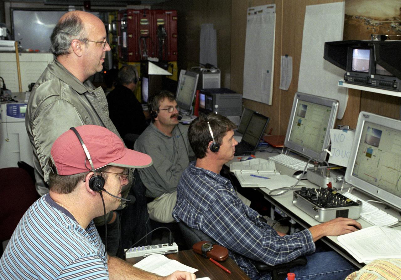
AeroVironment's test director Jim Daley, backup pilot Rik Meininger, stability and controls engineer Derek Lisoski and pilot Wyatt Sadler (clockwise from bottom left) closely monitor systems testing of the Pathfinder-Plus solar aircraft from the control station.

This is the 3rd entry of the TTBW model in 14x22. This test specifically is a lateral-directional test looking at the effects of 3D printed ventral, keel, and dorsal strakes on the stability and control characteristics of the model. Cooperative agreement between Boeing and NASA.
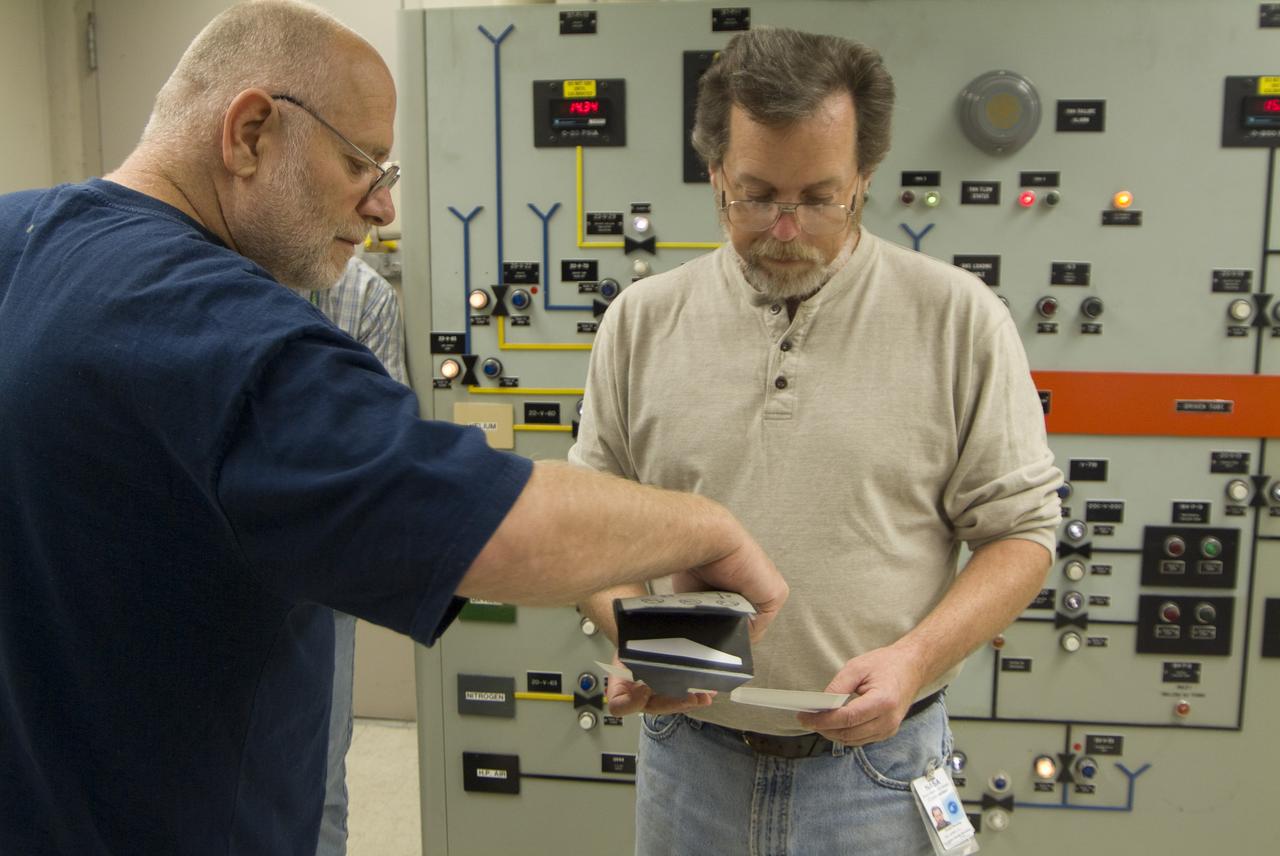
CEV (Crew Escape Vehicle) capsule Balistic Range testing to examine static and dynamic stability characteristics (at the Hypervelocity Free-Flight Facility) HFF - Don Holt (L) & Don Bowling (r) in control room examining poloroids
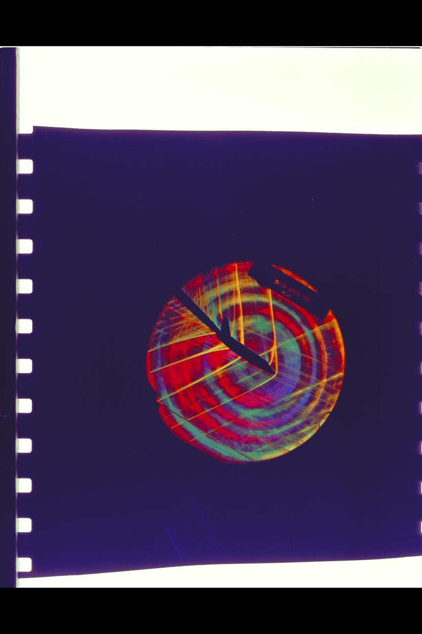
MSC Space Shuttle Stability and Control Characteristics. Schlieren of North American Rockwell Straight Wing orbiter approximate Mach .95 6ft w.t. Test-66-503
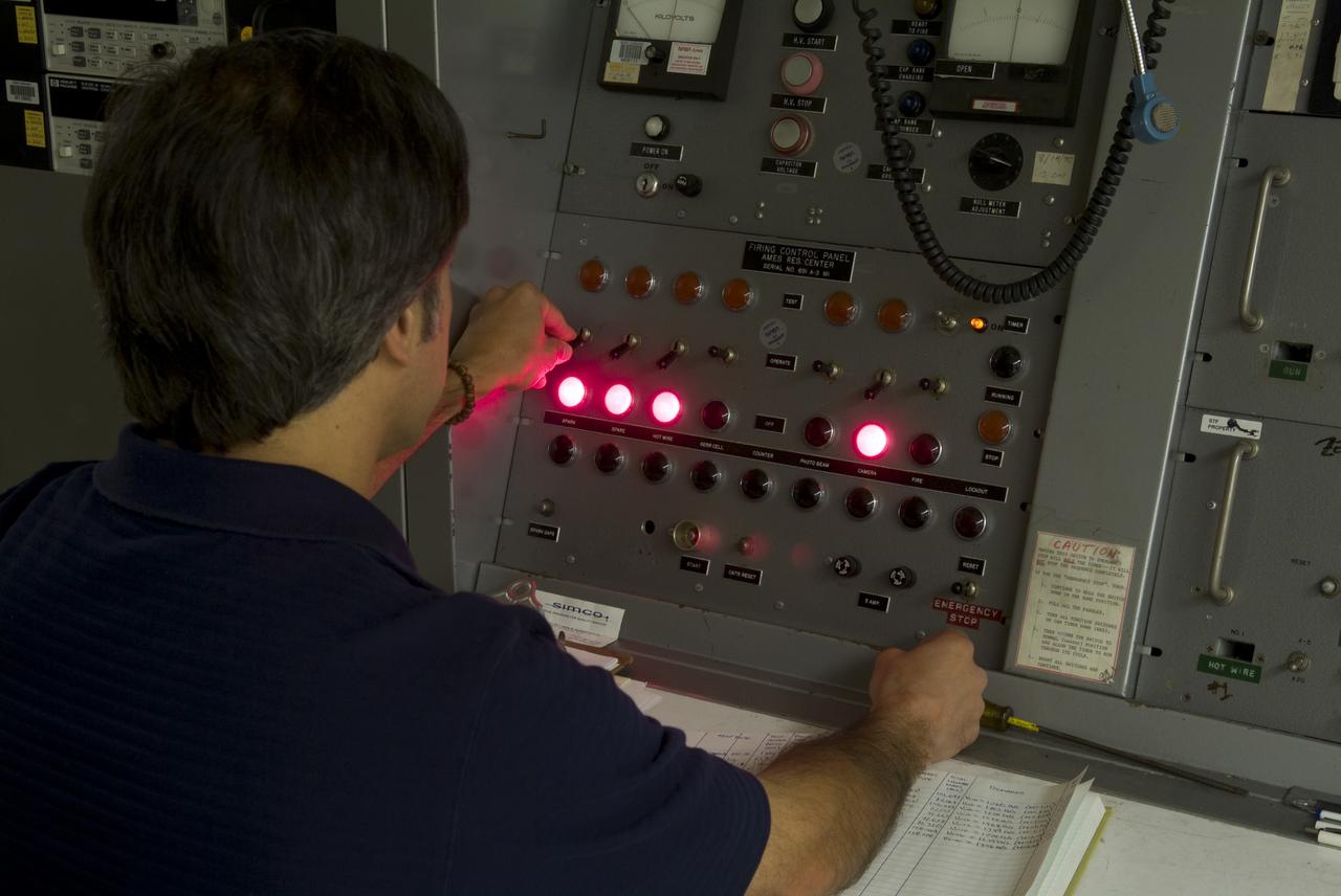
CEV (Crew Escape Vehicle) capsule Balistic Range testing to examine static and dynamic stability characteristics (at the Hypervelocity Free-Flight Facility) HFF Chuck Cornelison operating 'Firing' control pannel
MSC Space Shuttle Stability and Control Characteristics. Schlieren of North American Rockwell Straight Wing orbiter approximate Mach .95 6ft w.t. test-66-503
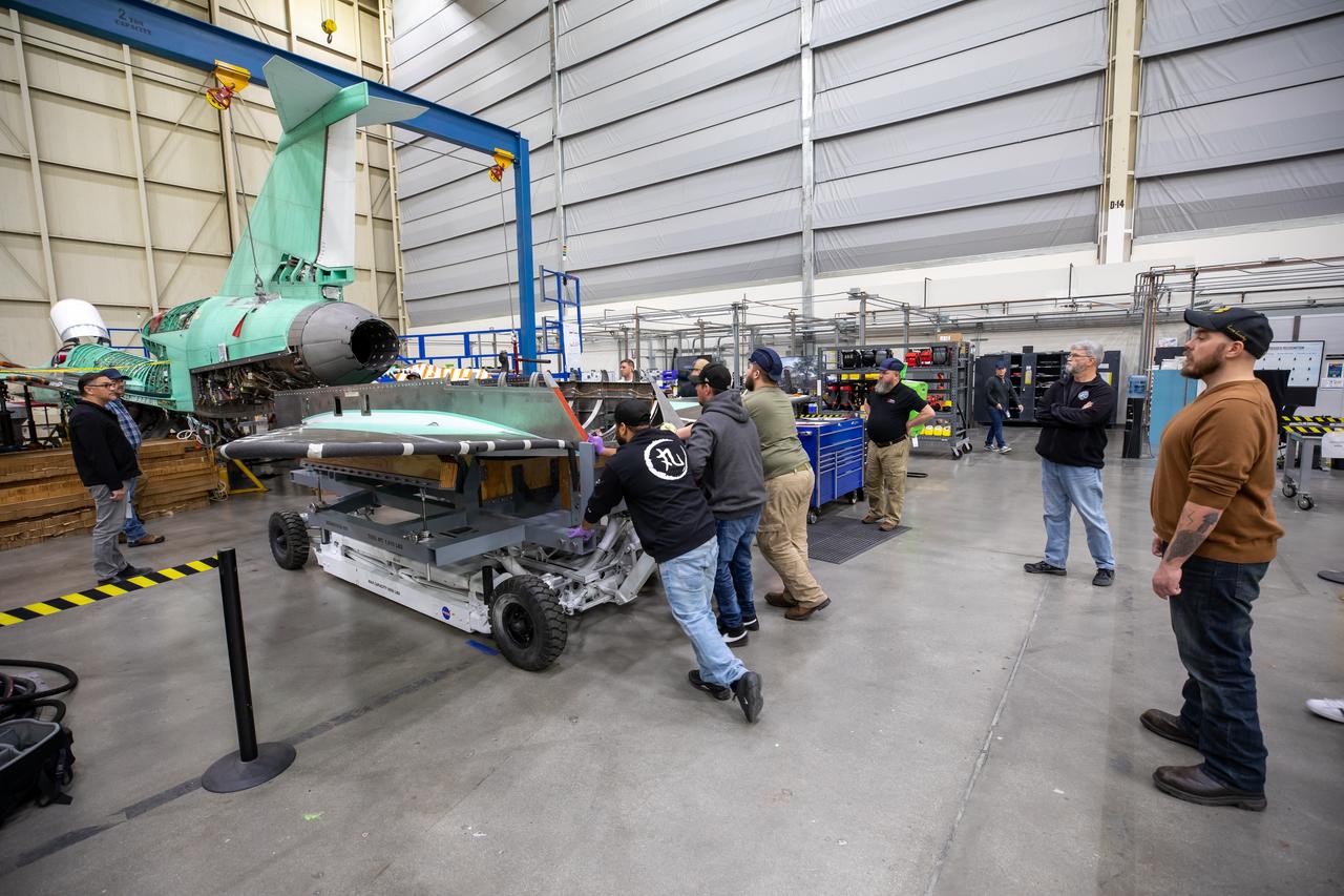
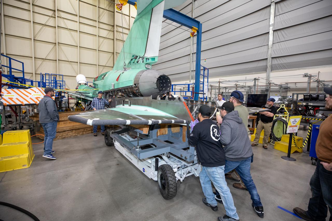
The X-59 team at Lockheed Martin Skunk Works in Palmdale, California, load the lower empennage - the tail section - into place. The surfaces used to control the tilt of the airplane are called stabilators and are connected to the lower empennage. The X-59 is the centerpiece of NASA’s Quesst mission, which could help enable commercial supersonic air travel over land.
The X-59 team at Lockheed Martin Skunk Works in Palmdale, California, load the lower empennage - the tail section - into place. The surfaces used to control the tilt of the airplane are called stabilators and are connected to the lower empennage. The X-59 is the centerpiece of NASA’s Quesst mission, which could help enable commercial supersonic air travel over land.
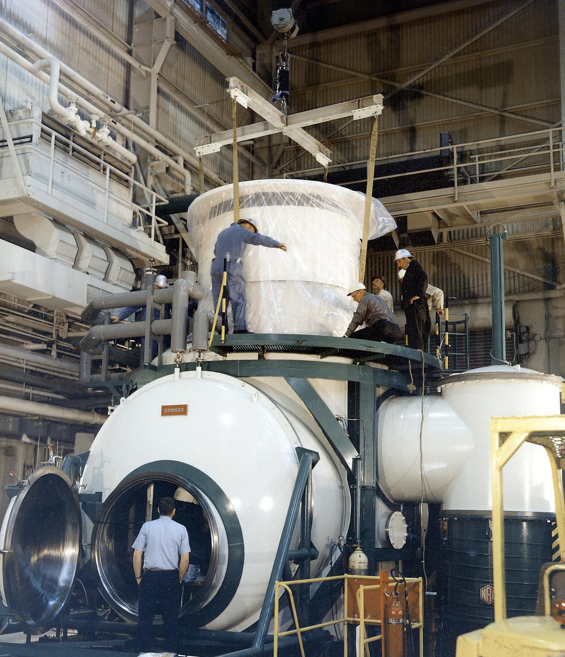
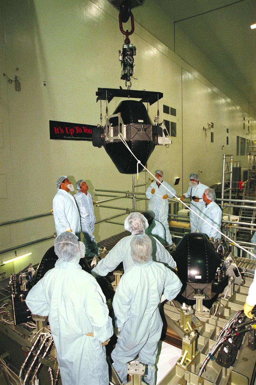
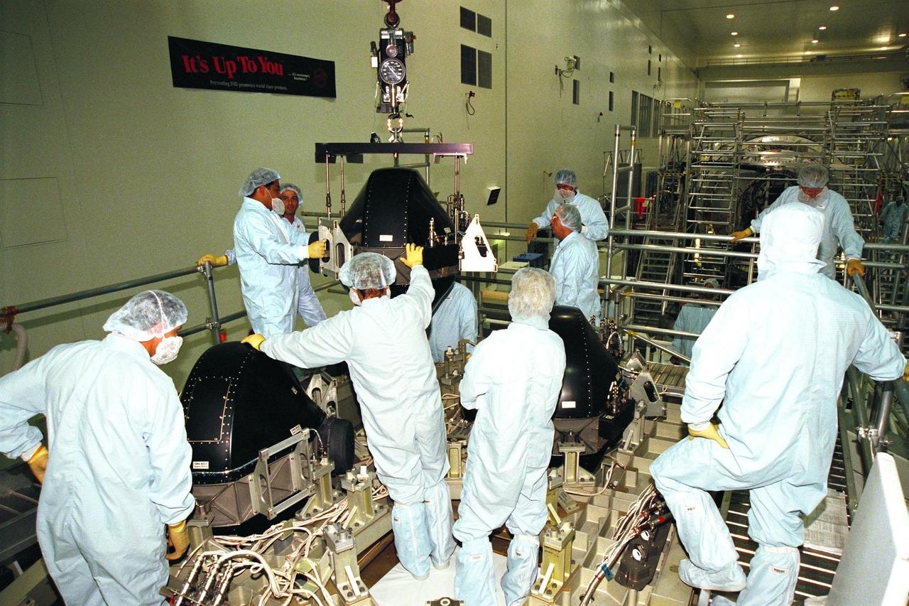
The Apollo Telescope Mount (ATM) was designed and developed by the Marshall Space Flight Center (MSFC) and served as the primary scientific instrument unit aboard Skylab (1973-1979). The ATM consisted of eight scientific instruments as well as a number of smaller experiments. In this image, the thermal unit, that controlled the temperature stability of the ATM, is being installed into a vacuum chamber.
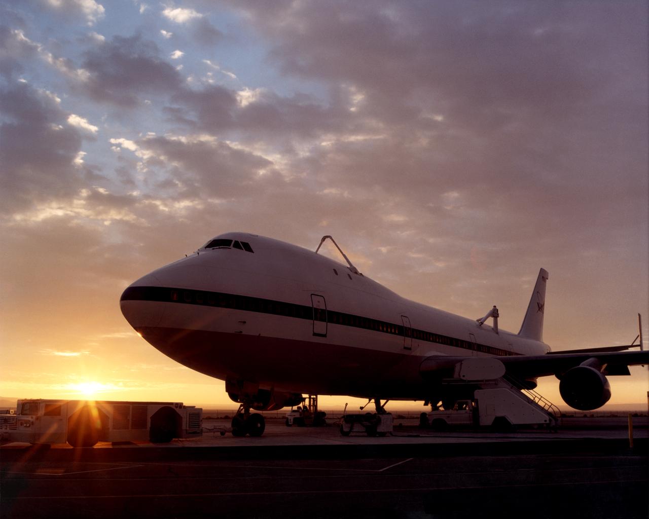
One of NASA’s two modified Boeing 747 Shuttle Carrier Aircraft is bathed in the morning Sun at NASA’s Dryden Flight Research Center at Edwards, California. The modified jumbo jetliners are used to ferry the Space Shuttle orbiters between Dryden and the Kennedy Space Center in Florida and Boeing’s Reusable Space Systems modification facility at Palmdale, California. Features which distinguish the two SCAs from standard 747 jetliners are three struts, with associated interior structural strengthening, which protrude from the top of the fuselage (two aft, one forward) on which the orbiter is attached, and two additional vertical stabilizers, one on each end of the standard horizontal stabilizer, to enhance directional stability. All interior furnishings and equipment aft of the forward No. 1 doors have also been removed to reduce weight. The two SCAs are under the operational control of NASA's Johnson Space Center, Houston, Texas.
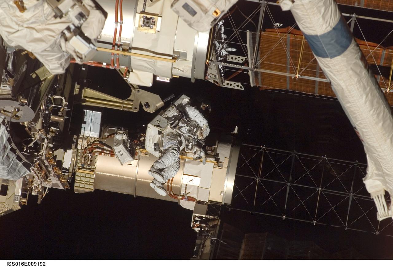
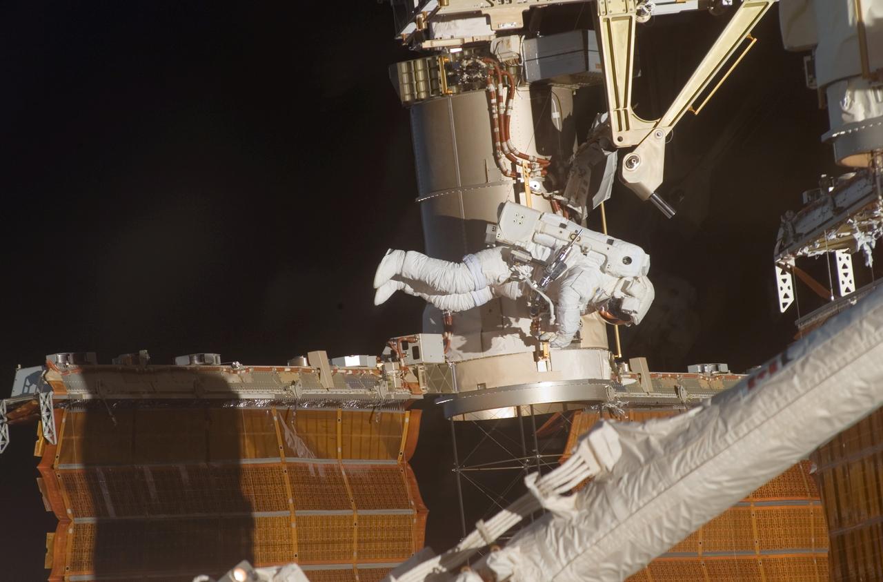
ISS016-E-009192 (3 Nov. 2007) --- Astronaut Doug Wheelock, STS-120 mission specialist, participates in the mission's fourth session of extravehicular activity (EVA) while Space Shuttle Discovery is docked with the International Space Station. During the 7-hour, 19-minute spacewalk, astronaut Scott Parazynski (out of frame), mission specialist, cut a snagged wire and installed homemade stabilizers designed to strengthen the damaged solar array's structure and stability in the vicinity of the damage. Wheelock assisted from the truss by keeping an eye on the distance between Parazynski and the array. Once the repair was complete, flight controllers on the ground successfully completed the deployment of the array.
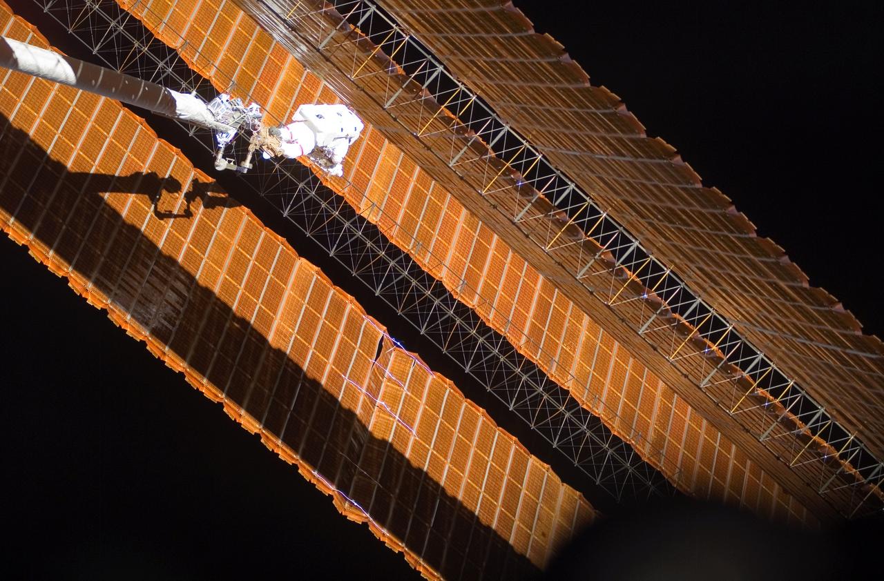
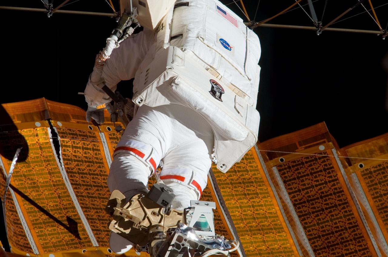
While anchored to a foot restraint on the end of the Orbiter Boom Sensor System (OBSS), astronaut Scott Parazynski, STS-120 mission specialist, participated in the mission's fourth session of extravehicular activity (EVA) while Space Shuttle Discovery was docked with the International Space Station (ISS). During the 7-hour and 19-minute space walk, Parazynski cut a snagged wire and installed homemade stabilizers designed to strengthen the structure and stability of the damaged P6 4B solar array wing. Astronaut Doug Wheelock (out of frame), mission specialist, assisted from the truss by keeping an eye on the distance between Parazynski and the array. Once the repair was complete, flight controllers on the ground successfully completed the deployment of the array.
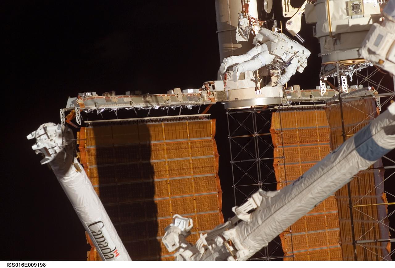
ISS016-E-009198 (3 Nov. 2007) --- Astronaut Doug Wheelock, STS-120 mission specialist, participates in the mission's fourth session of extravehicular activity (EVA) while Space Shuttle Discovery is docked with the International Space Station. During the 7-hour, 19-minute spacewalk, astronaut Scott Parazynski (out of frame), mission specialist, cut a snagged wire and installed homemade stabilizers designed to strengthen the damaged solar array's structure and stability in the vicinity of the damage. Wheelock assisted from the truss by keeping an eye on the distance between Parazynski and the array. Once the repair was complete, flight controllers on the ground successfully completed the deployment of the array.
Astronaut Doug Wheelock, STS-120 mission specialist, participated in the mission's fourth session of extravehicular activity (EVA) while Space Shuttle Discovery was docked with the International Space Station (ISS). During the 7-hour and 19-minute space walk, astronaut Scott Parazynski (out of frame), mission specialist, cut a snagged wire and installed homemade stabilizers designed to strengthen the structure and stability of the damaged P6 4B solar array wing. Wheelock assisted from the truss by keeping an eye on the distance between Parazynski and the array. Once the repair was complete, flight controllers on the ground successfully completed the deployment of the array.
While anchored to a foot restraint on the end of the Orbiter Boom Sensor System (OBSS), astronaut Scott Parazynski, STS-120 mission specialist, participated in the mission's fourth session of extravehicular activity (EVA) while Space Shuttle Discovery was docked with the International Space Station (ISS). During the 7-hour and 19-minute space walk, Parazynski cut a snagged wire and installed homemade stabilizers designed to strengthen the structure and stability of the damaged P6 4B solar array wing. Astronaut Doug Wheelock (out of frame), mission specialist, assisted from the truss by keeping an eye on the distance between Parazynski and the array. Once the repair was complete, flight controllers on the ground successfully completed the deployment of the array.
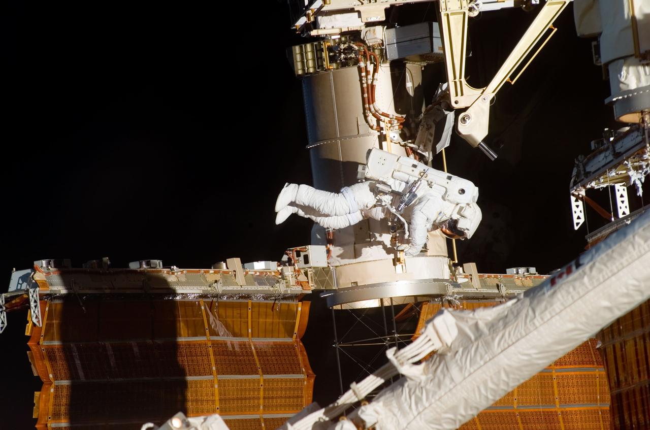
ISS016-E-009179 (3 Nov. 2007) --- Astronaut Doug Wheelock, STS-120 mission specialist, participates in the mission's fourth session of extravehicular activity (EVA) while Space Shuttle Discovery is docked with the International Space Station. During the 7-hour, 19-minute spacewalk, astronaut Scott Parazynski (out of frame), mission specialist, cut a snagged wire and installed homemade stabilizers designed to strengthen the damaged solar array's structure and stability in the vicinity of the damage. Wheelock assisted from the truss by keeping an eye on the distance between Parazynski and the array. Once the repair was complete, flight controllers on the ground successfully completed the deployment of the array.
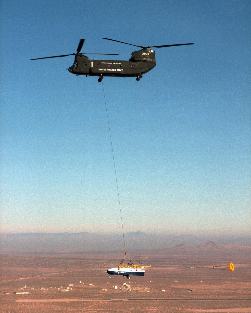
With a small stabilization parachute trailing behind, the X-40 sub-scale technology demonstrator is suspended under a U.S. Army CH-47 Chinook cargo helicopter during a captive-carry test flight at NASA's Dryden Flight Research Center, Edwards, California. The captive carry flights are designed to verify the X-40's navigation and control systems, rigging angles for its sling, and stability and control of the helicopter while carrying the X-40 on a tether. Following a series of captive-carry flights, the X-40 made free flights from a launch altitude of about 15,000 feet above ground, gliding to a fully autonomous landing. The X-40 is an unpowered 82 percent scale version of the X-37, a Boeing-developed spaceplane designed to demonstrate various advanced technologies for development of future lower-cost access to space vehicles.
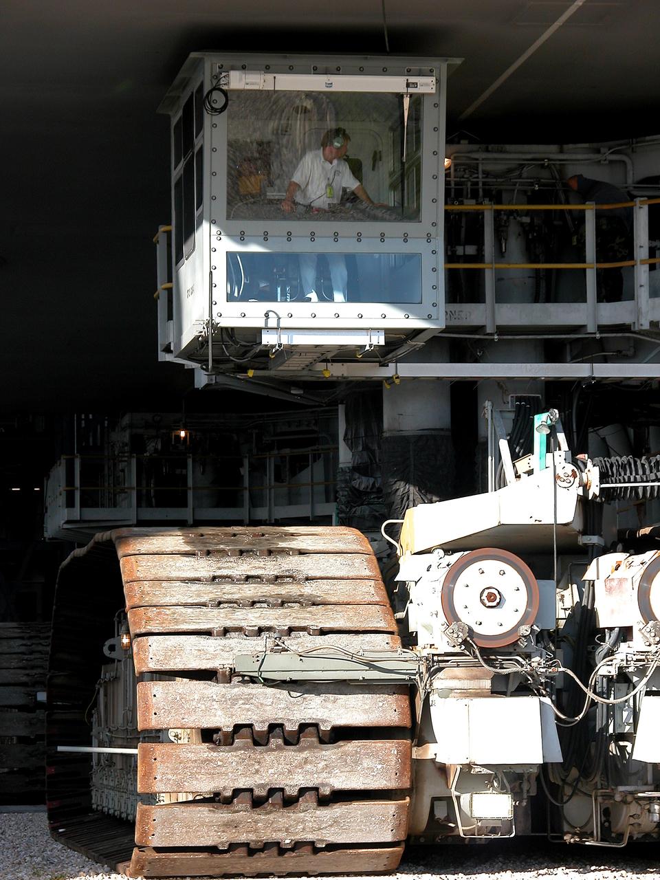
KENNEDY SPACE CENTER, FLA. - As the crawler transporter slowly moves the Mobile Launcher Platform (MLP) out of the Vehicle Assembly Building, the driver of the front control cab can be seen. The MLP is carrying two solid rocket boosters for engineering analysis vibration tests on the crawler and MLP. The crawler is moving at various speeds up to 1 mph in an effort to achieve vibration data gathering goals as it leaves the VAB and then returns. The boosters are braced at the top for stability. The primary purpose of these rollout tests is to gather data to develop future maintenance requirements on the transport equipment and the flight hardware. Various parts of the MLP and crawler transporter have been instrumented with vibration data collection equipment.
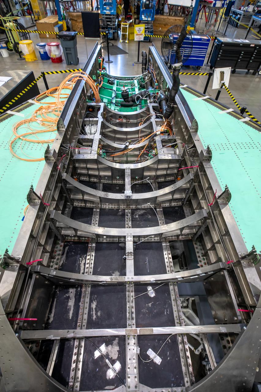
This image shows the X-59 aircraft’s lower empennage structure, or tail section of the plane, that was installed. The stabilators, the outer surfaces also seen in the photo, attach to the lower empennage and are used to help regulate the aircraft pitch which controls the up and down movement of the motion of the plane. The 13-foot engine will pack 22,000 pounds of propulsion and energy and power the X-plane to its planned cruising speed of Mach 1.4. Once complete, the X-59 aircraft will demonstrate the ability to fly supersonic while reducing the loud sonic boom to a quiet sonic thump and help enable commercial supersonic air travel over land. This aircraft is the centerpiece of NASA’s Quesst mission.
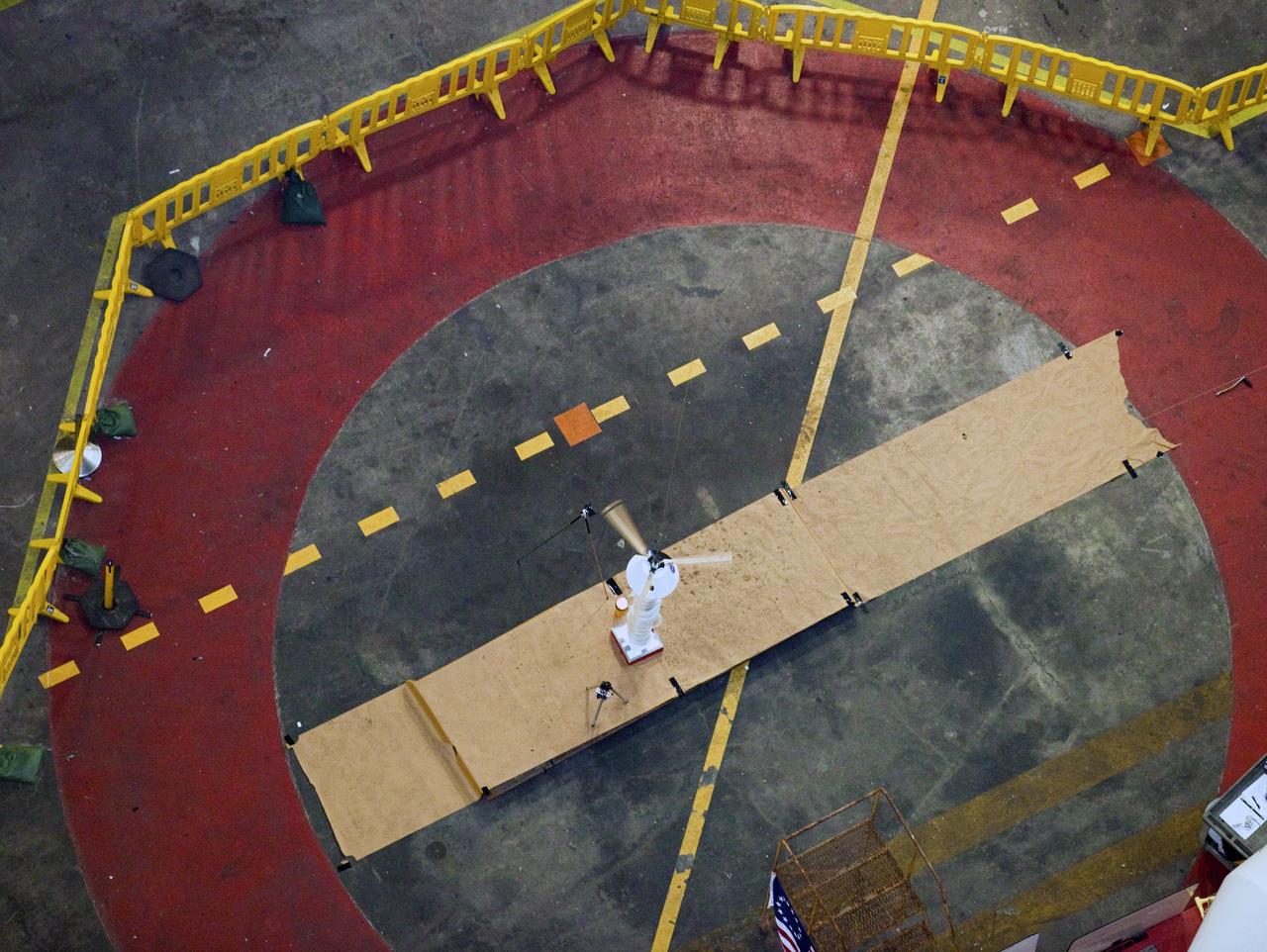
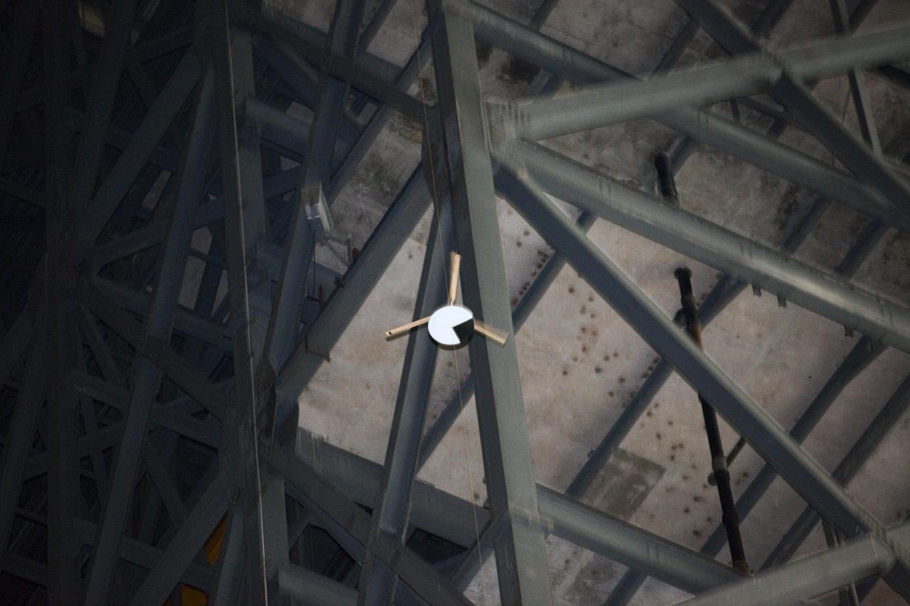
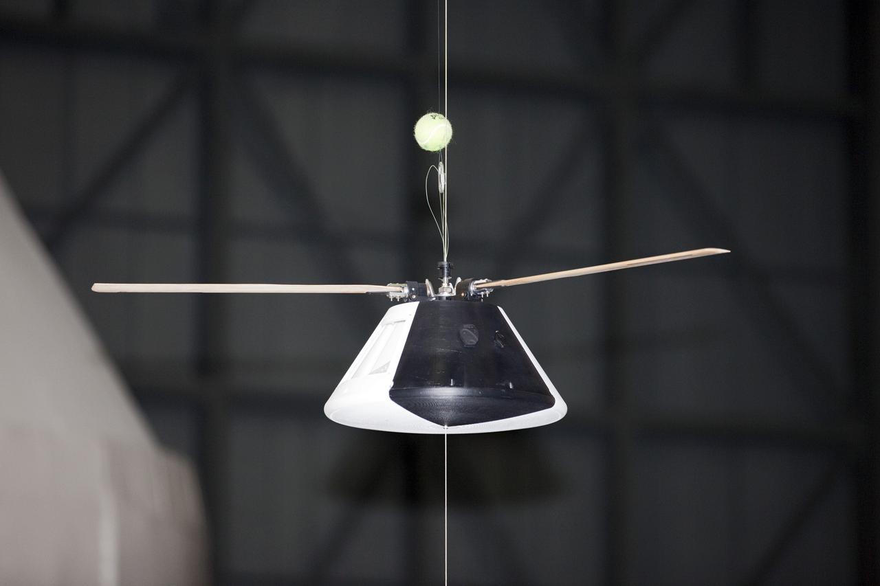
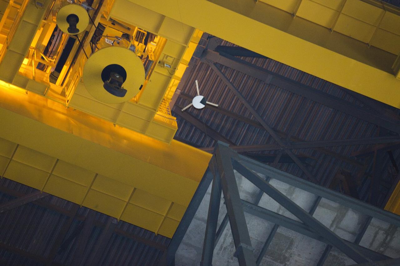
CAPE CANAVERAL, Fla. - A model capsule falls during tests inside the Vehicle Assembly Building at NASA's Kennedy Space Center in Florida to test a rotor system landing design. The design would give a capsule the stability and control of a helicopter, but would not be powered. Instead, the wind passing over the rotors as the capsule descends would make the blades turn, a process called auto-rotation. The intent is to give real spacecraft a soft landing with enough control that they could touch down anywhere in the world, whether it be a runway or parking lot. In other words, wherever a helicopter could land, a spacecraft could land, too. Photo credit: NASA/Kim Shiflett
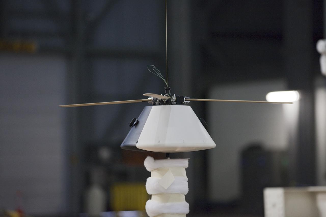
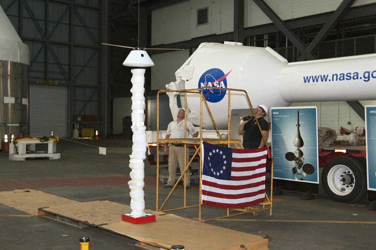
CAPE CANAVERAL, Fla. - A model capsule seen ahead of tests inside the Vehicle Assembly Building at NASA's Kennedy Space Center in Florida to test a rotor system landing design. The design would give a capsule the stability and control of a helicopter, but would not be powered. Instead, the wind passing over the rotors as the capsule descends would make the blades turn, a process called auto-rotation. The intent is to give real spacecraft a soft landing with enough control that they could touch down anywhere in the world, whether it be a runway or parking lot. In other words, wherever a helicopter could land, a spacecraft could land, too. Photo credit: NASA/Kim Shiflett
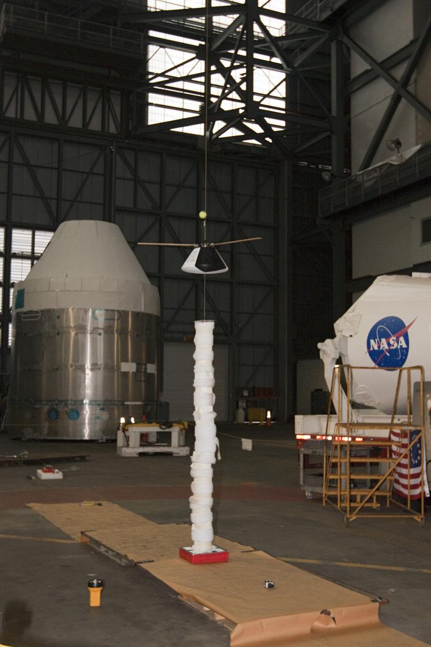
CAPE CANAVERAL, Fla. - A model capsule seen ahead of tests inside the Vehicle Assembly Building at NASA's Kennedy Space Center in Florida to test a rotor system landing design. The design would give a capsule the stability and control of a helicopter, but would not be powered. Instead, the wind passing over the rotors as the capsule descends would make the blades turn, a process called auto-rotation. The intent is to give real spacecraft a soft landing with enough control that they could touch down anywhere in the world, whether it be a runway or parking lot. In other words, wherever a helicopter could land, a spacecraft could land, too. Photo credit: NASA/Kim Shiflett
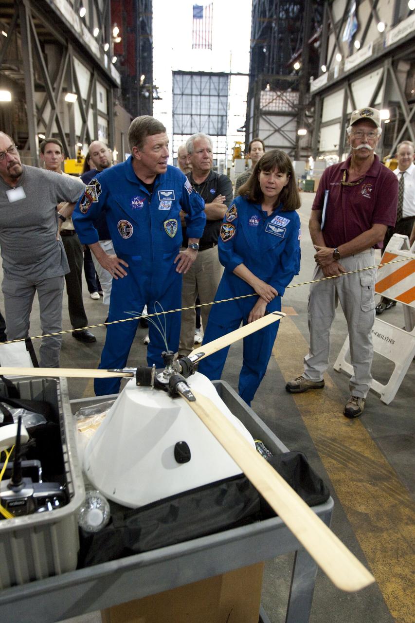
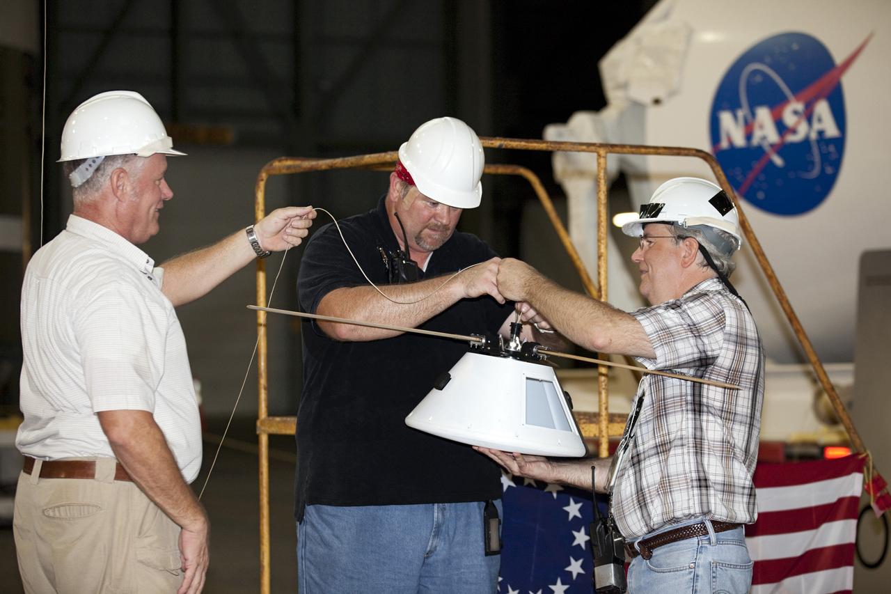
CAPE CANAVERAL, Fla. - Astronauts Mike Fossum and Cady Coleman look over a model capsule fit with rotor blades ahead of tests inside the Vehicle Assembly Building at NASA's Kennedy Space Center in Florida. The design would give a capsule the stability and control of a helicopter, but would not be powered. Instead, the wind passing over the rotors as the capsule descends would make the blades turn, a process called auto-rotation. The intent is to give real spacecraft a soft landing with enough control that they could touch down anywhere in the world, whether it be a runway or parking lot. In other words, wherever a helicopter could land, a spacecraft could land, too. Photo credit: NASA/Kim Shiflett
CAPE CANAVERAL, Fla. - Test operators examine a model capsule after a of test inside the Vehicle Assembly Building at NASA's Kennedy Space Center in Florida to test a rotor system landing design. The design would give a capsule the stability and control of a helicopter, but would not be powered. Instead, the wind passing over the rotors as the capsule descends would make the blades turn, a process called auto-rotation. The intent is to give real spacecraft a soft landing with enough control that they could touch down anywhere in the world, whether it be a runway or parking lot. In other words, wherever a helicopter could land, a spacecraft could land, too. Photo credit: NASA/Kim Shiflett
CAPE CANAVERAL, Fla. - A model capsule seen ahead of tests inside the Vehicle Assembly Building at NASA's Kennedy Space Center in Florida to test a rotor system landing design. The design would give a capsule the stability and control of a helicopter, but would not be powered. Instead, the wind passing over the rotors as the capsule descends would make the blades turn, a process called auto-rotation. The intent is to give real spacecraft a soft landing with enough control that they could touch down anywhere in the world, whether it be a runway or parking lot. In other words, wherever a helicopter could land, a spacecraft could land, too. Photo credit: NASA/Kim Shiflett
CAPE CANAVERAL, Fla. - A model capsule following a test inside the Vehicle Assembly Building at NASA's Kennedy Space Center in Florida to test a rotor system landing design. The design would give a capsule the stability and control of a helicopter, but would not be powered. Instead, the wind passing over the rotors as the capsule descends would make the blades turn, a process called auto-rotation. The intent is to give real spacecraft a soft landing with enough control that they could touch down anywhere in the world, whether it be a runway or parking lot. In other words, wherever a helicopter could land, a spacecraft could land, too. Photo credit: NASA/Kim Shiflett
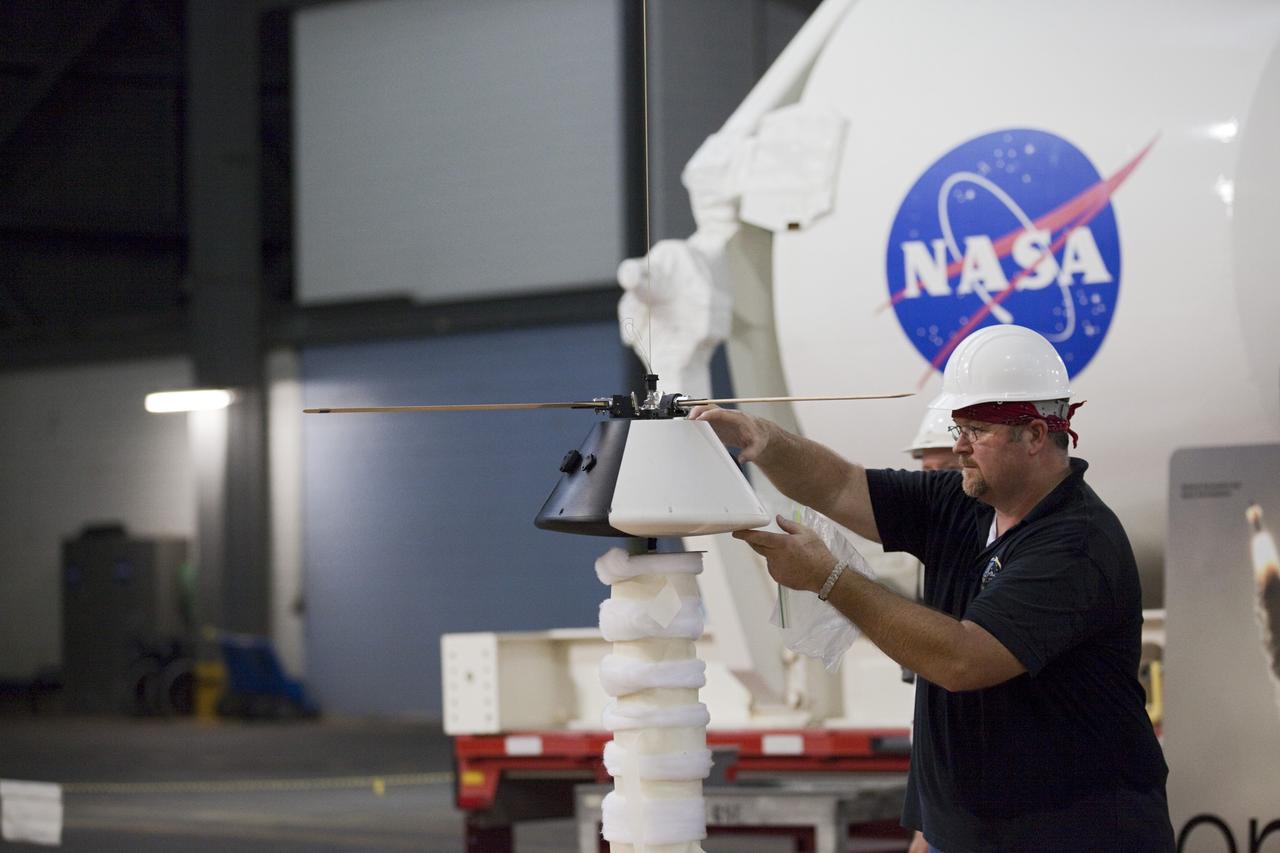
CAPE CANAVERAL, Fla. - Test operators prepare a model capsule ahead of tests inside the Vehicle Assembly Building at NASA's Kennedy Space Center in Florida to test a rotor system landing design. The design would give a capsule the stability and control of a helicopter, but would not be powered. Instead, the wind passing over the rotors as the capsule descends would make the blades turn, a process called auto-rotation. The intent is to give real spacecraft a soft landing with enough control that they could touch down anywhere in the world, whether it be a runway or parking lot. In other words, wherever a helicopter could land, a spacecraft could land, too. Photo credit: NASA/Kim Shiflett
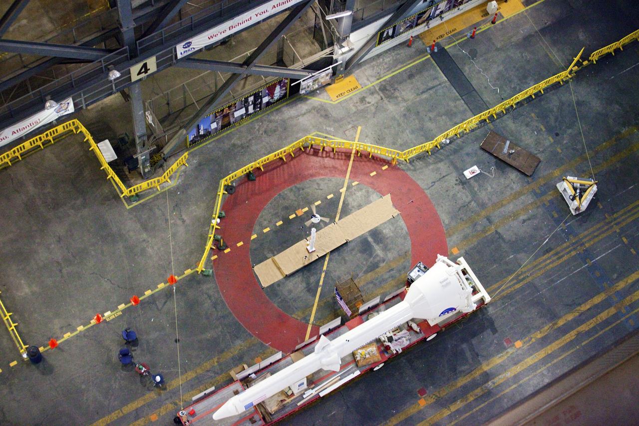
CAPE CANAVERAL, Fla. - A model capsule falls during tests inside the Vehicle Assembly Building at NASA's Kennedy Space Center in Florida to test a rotor system landing design. The design would give a capsule the stability and control of a helicopter, but would not be powered. Instead, the wind passing over the rotors as the capsule descends would make the blades turn, a process called auto-rotation. The intent is to give real spacecraft a soft landing with enough control that they could touch down anywhere in the world, whether it be a runway or parking lot. In other words, wherever a helicopter could land, a spacecraft could land, too. Photo credit: NASA/Kim Shiflett
CAPE CANAVERAL, Fla. - NASA Aerospace Engineer Jeff Hagen prepares a model capsule ahead of tests inside the Vehicle Assembly Building at NASA's Kennedy Space Center in Florida to test a rotor system landing design. The design would give a capsule the stability and control of a helicopter, but would not be powered. Instead, the wind passing over the rotors as the capsule descends would make the blades turn, a process called auto-rotation. The intent is to give real spacecraft a soft landing with enough control that they could touch down anywhere in the world, whether it be a runway or parking lot. In other words, wherever a helicopter could land, a spacecraft could land, too. Photo credit: NASA/Kim Shiflett
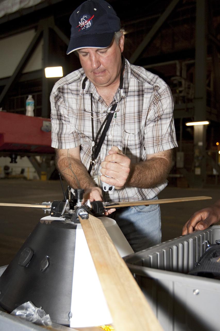
CAPE CANAVERAL, Fla. - NASA's Johnson Space Center Aerospace Engineer Jeff Hagen attaches a rotor to the top of a model capsule ahead of tests inside the Vehicle Assembly Building at NASA's Kennedy Space Center in Florida. The design would give a capsule the stability and control of a helicopter, but would not be powered. Instead, the wind passing over the rotors as the capsule descends would make the blades turn, a process called auto-rotation. The intent is to give real spacecraft a soft landing with enough control that they could touch down anywhere in the world, whether it be a runway or parking lot. In other words, wherever a helicopter could land, a spacecraft could land, too. Photo credit: NASA/Kim Shiflett
CAPE CANAVERAL, Fla. - A model capsule seen ahead of tests inside the Vehicle Assembly Building at NASA's Kennedy Space Center in Florida to test a rotor system landing design. The design would give a capsule the stability and control of a helicopter, but would not be powered. Instead, the wind passing over the rotors as the capsule descends would make the blades turn, a process called auto-rotation. The intent is to give real spacecraft a soft landing with enough control that they could touch down anywhere in the world, whether it be a runway or parking lot. In other words, wherever a helicopter could land, a spacecraft could land, too. Photo credit: NASA/Kim Shiflett
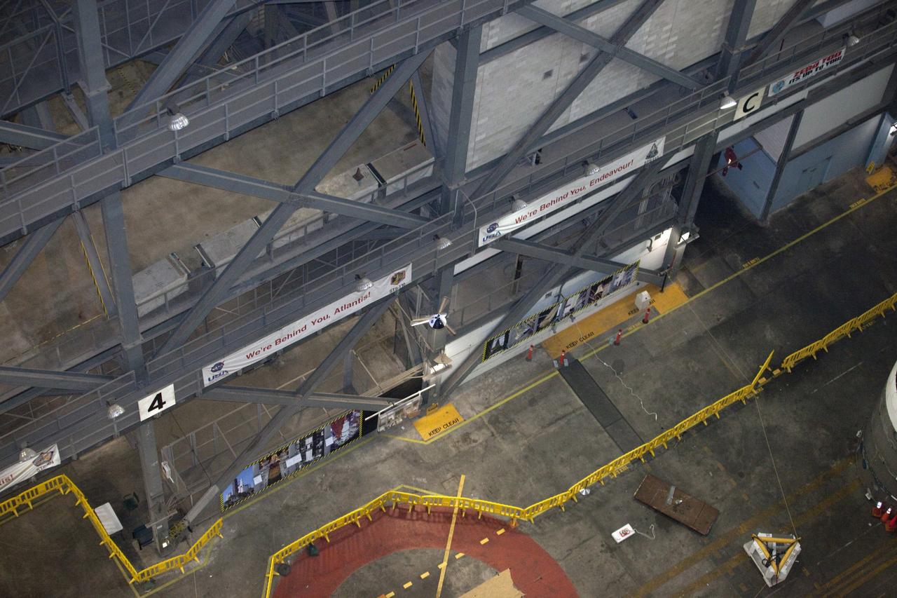
CAPE CANAVERAL, Fla. - A model capsule falls during tests inside the Vehicle Assembly Building at NASA's Kennedy Space Center in Florida to test a rotor system landing design. The design would give a capsule the stability and control of a helicopter, but would not be powered. Instead, the wind passing over the rotors as the capsule descends would make the blades turn, a process called auto-rotation. The intent is to give real spacecraft a soft landing with enough control that they could touch down anywhere in the world, whether it be a runway or parking lot. In other words, wherever a helicopter could land, a spacecraft could land, too. Photo credit: NASA/Kim Shiflett
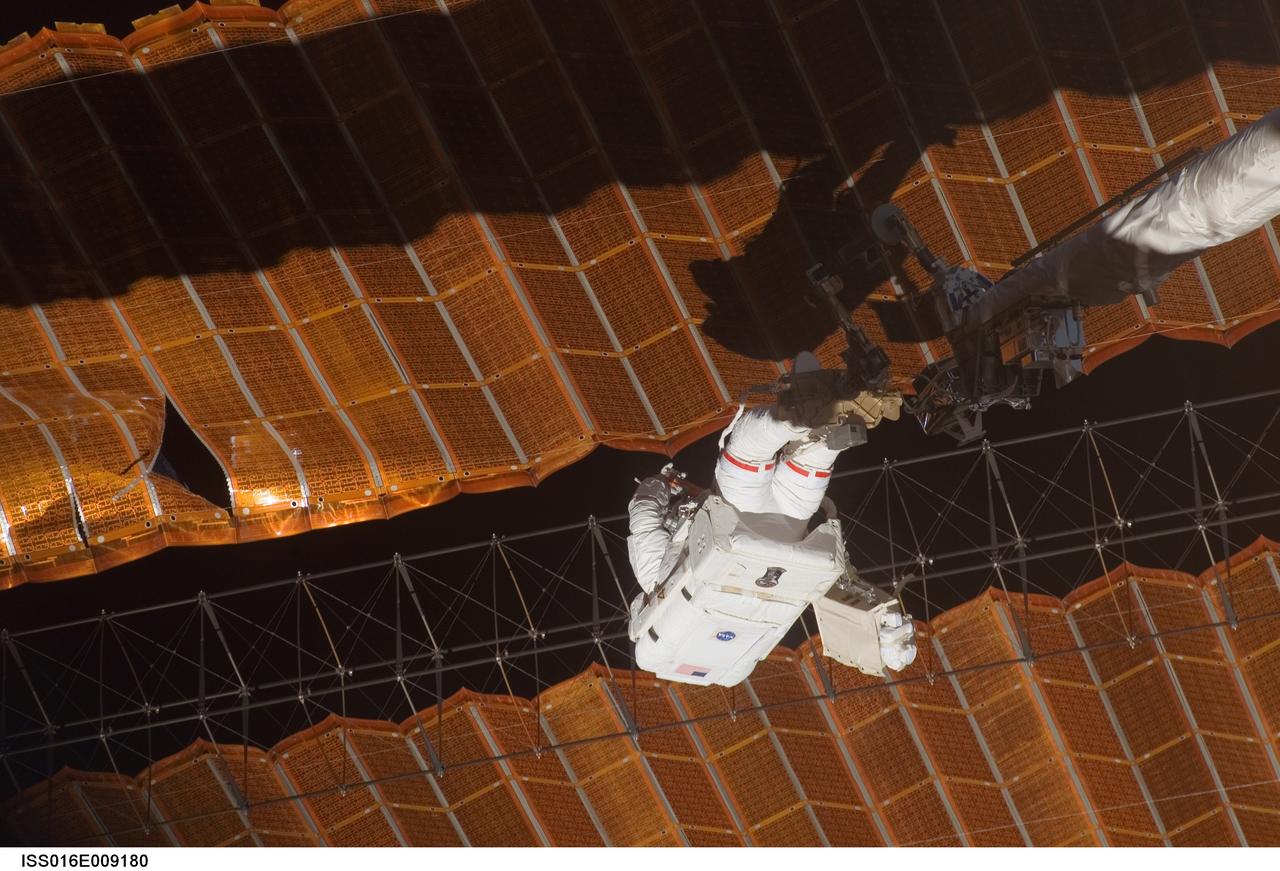
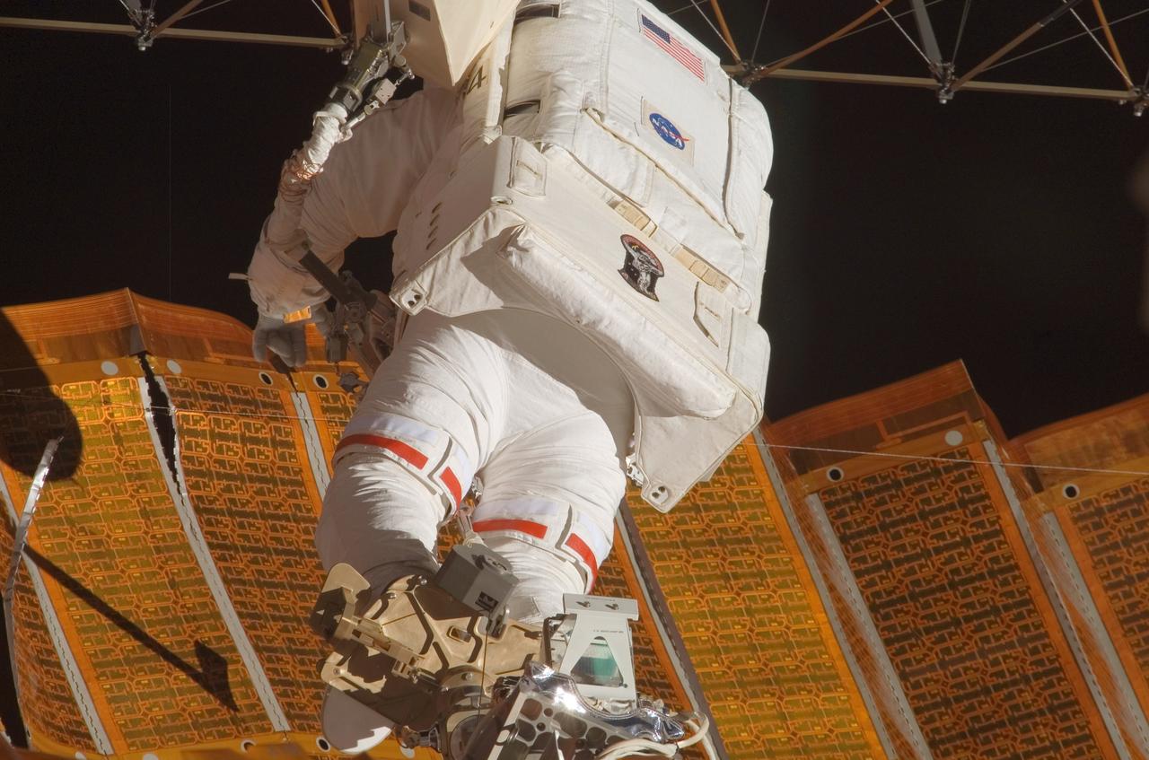
ISS016-E-009180 (3 Nov. 2007) --- While anchored to a foot restraint on the end of the Orbiter Boom Sensor System (OBSS), astronaut Scott Parazynski, STS-120 mission specialist, participates in the mission's fourth session of extravehicular activity (EVA) while Space Shuttle Discovery is docked with the International Space Station. During the 7-hour, 19-minute spacewalk, Parazynski cut a snagged wire and installed homemade stabilizers designed to strengthen the damaged solar array's structure and stability in the vicinity of the damage. Astronaut Doug Wheelock (out of frame), mission specialist, assisted from the truss by keeping an eye on the distance between Parazynski and the array. Once the repair was complete, flight controllers on the ground successfully completed the deployment of the array.
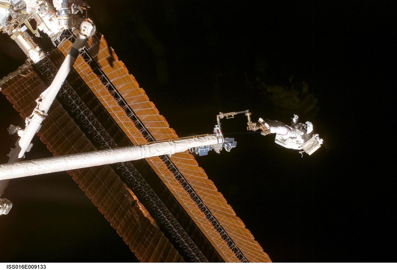
ISS016-E-009133 (3 Nov. 2007) --- While anchored to a foot restraint on the end of the Orbiter Boom Sensor System (OBSS), astronaut Scott Parazynski, STS-120 mission specialist, participates in the mission's fourth session of extravehicular activity (EVA) while Space Shuttle Discovery is docked with the International Space Station. During the 7-hour, 19-minute spacewalk, Parazynski cut a snagged wire and installed homemade stabilizers designed to strengthen the damaged solar array's structure and stability in the vicinity of the damage. Astronaut Doug Wheelock (out of frame), mission specialist, assisted from the truss by keeping an eye on the distance between Parazynski and the array. Once the repair was complete, flight controllers on the ground successfully completed the deployment of the array.
ISS016-E-009135 (3 Nov. 2007) --- While anchored to a foot restraint on the end of the Orbiter Boom Sensor System (OBSS), astronaut Scott Parazynski, STS-120 mission specialist, participates in the mission's fourth session of extravehicular activity (EVA) while Space Shuttle Discovery is docked with the International Space Station. During the 7-hour, 19-minute spacewalk, Parazynski cut a snagged wire and installed homemade stabilizers designed to strengthen the damaged solar array's structure and stability in the vicinity of the damage. Astronaut Doug Wheelock (out of frame), mission specialist, assisted from the truss by keeping an eye on the distance between Parazynski and the array. Once the repair was complete, flight controllers on the ground successfully completed the deployment of the array.
ISS016-E-009184 (3 Nov. 2007) --- While anchored to a foot restraint on the end of the Orbiter Boom Sensor System (OBSS), astronaut Scott Parazynski, STS-120 mission specialist, participates in the mission's fourth session of extravehicular activity (EVA) while Space Shuttle Discovery is docked with the International Space Station. During the 7-hour, 19-minute spacewalk, Parazynski cut a snagged wire and installed homemade stabilizers designed to strengthen the damaged solar array's structure and stability in the vicinity of the damage. Astronaut Doug Wheelock (out of frame), mission specialist, assisted from the truss by keeping an eye on the distance between Parazynski and the array. Once the repair was complete, flight controllers on the ground successfully completed the deployment of the array.
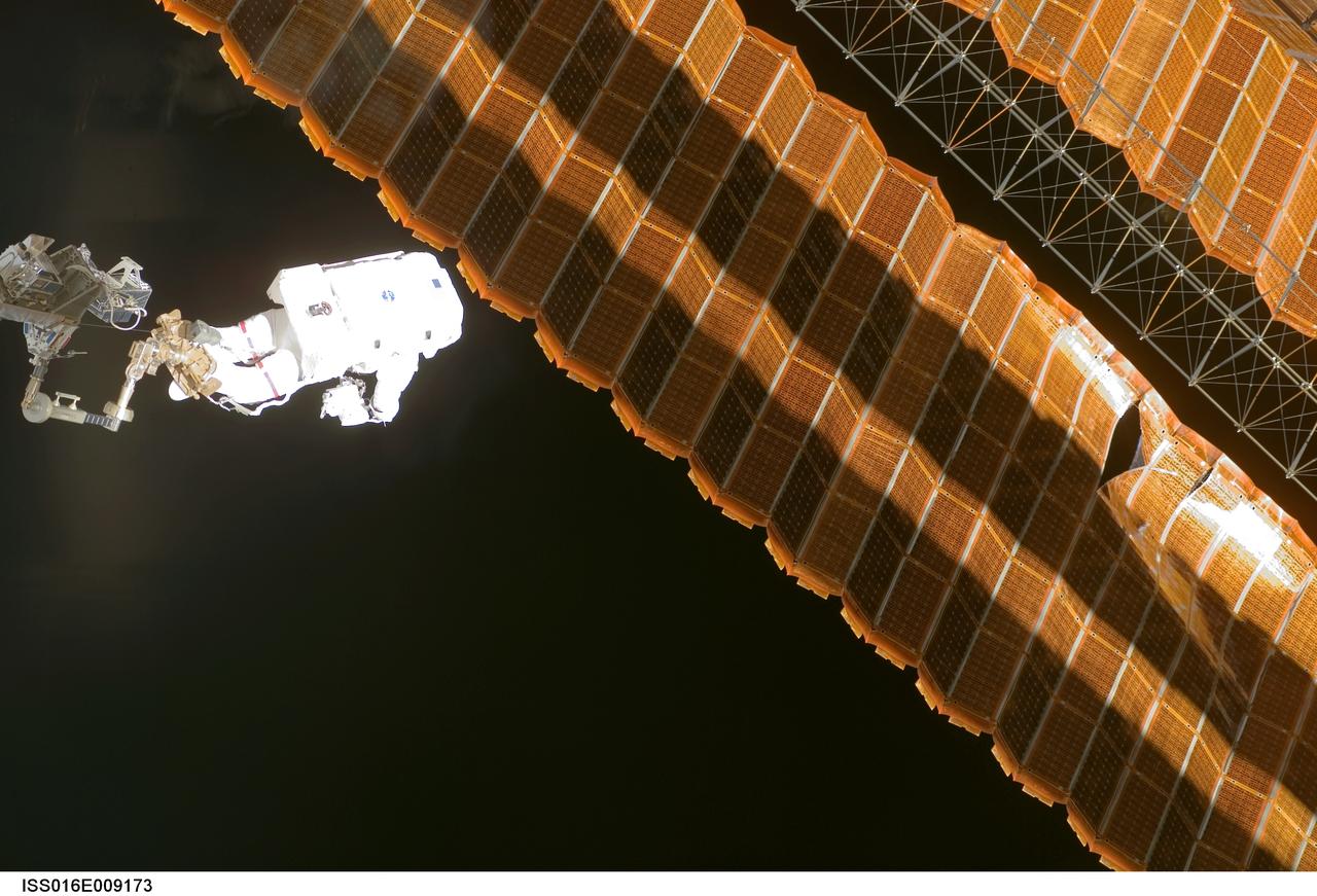
ISS016-E-009173 (3 Nov. 2007) --- While anchored to a foot restraint on the end of the Orbiter Boom Sensor System (OBSS), astronaut Scott Parazynski, STS-120 mission specialist, participates in the mission's fourth session of extravehicular activity (EVA) while Space Shuttle Discovery is docked with the International Space Station. During the 7-hour, 19-minute spacewalk, Parazynski cut a snagged wire and installed homemade stabilizers designed to strengthen the damaged solar array's structure and stability in the vicinity of the damage. Astronaut Doug Wheelock (out of frame), mission specialist, assisted from the truss by keeping an eye on the distance between Parazynski and the array. Once the repair was complete, flight controllers on the ground successfully completed the deployment of the array.
ISS016-E-008873 (3 Nov. 2007) --- While anchored to a foot restraint on the end of the Orbiter Boom Sensor System (OBSS), astronaut Scott Parazynski, STS-120 mission specialist, participates in the mission's fourth session of extravehicular activity (EVA) while Space Shuttle Discovery is docked with the International Space Station. During the 7-hour, 19-minute spacewalk, Parazynski cut a snagged wire and installed homemade stabilizers designed to strengthen the damaged solar array's structure and stability in the vicinity of the damage. Astronaut Doug Wheelock (out of frame), mission specialist, assisted from the truss by keeping an eye on the distance between Parazynski and the array. Once the repair was complete, flight controllers on the ground successfully completed the deployment of the array.
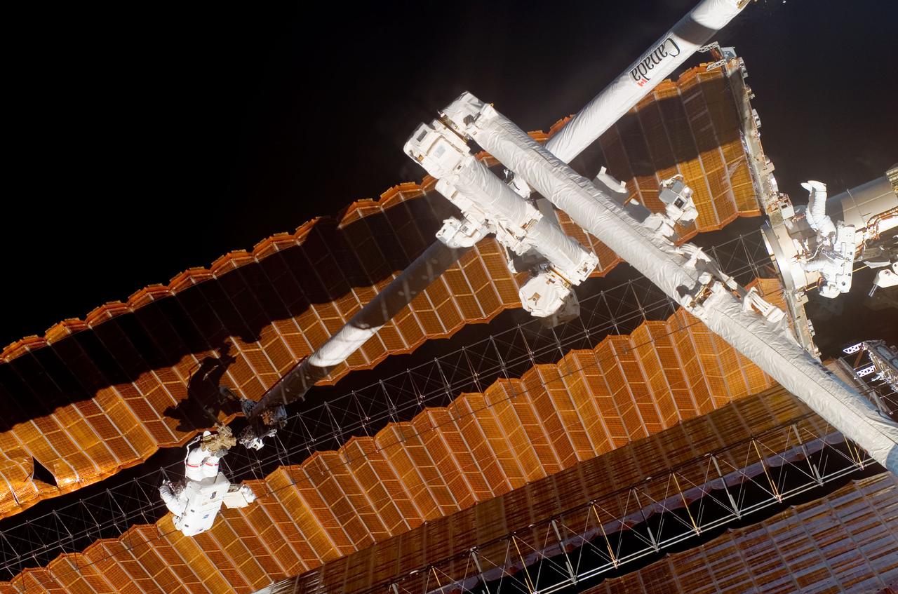
ISS016-E-009182 (3 Nov. 2007) --- While anchored to a foot restraint on the end of the Orbiter Boom Sensor System (OBSS), astronaut Scott Parazynski, STS-120 mission specialist, participates in the mission's fourth session of extravehicular activity (EVA) while Space Shuttle Discovery is docked with the International Space Station. During the 7-hour, 19-minute spacewalk, Parazynski cut a snagged wire and installed homemade stabilizers designed to strengthen the damaged solar array's structure and stability in the vicinity of the damage. Astronaut Doug Wheelock (right), mission specialist, assisted from the truss by keeping an eye on the distance between Parazynski and the array. Once the repair was complete, flight controllers on the ground successfully completed the deployment of the array.
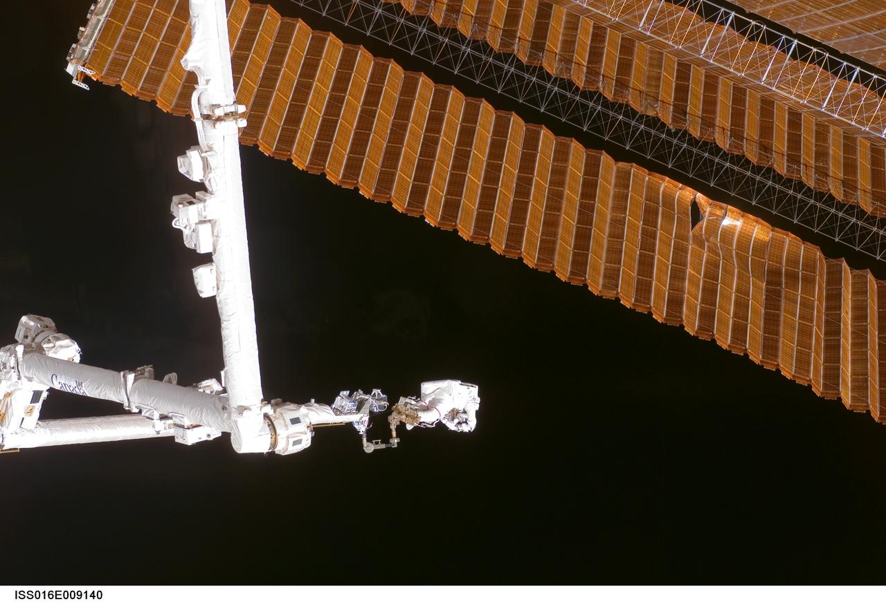
ISS016-E-009140 (3 Nov. 2007) --- While anchored to a foot restraint on the end of the Orbiter Boom Sensor System (OBSS), astronaut Scott Parazynski, STS-120 mission specialist, participates in the mission's fourth session of extravehicular activity (EVA) while Space Shuttle Discovery is docked with the International Space Station. During the 7-hour, 19-minute spacewalk, Parazynski cut a snagged wire and installed homemade stabilizers designed to strengthen the damaged solar array's structure and stability in the vicinity of the damage. Astronaut Doug Wheelock (out of frame), mission specialist, assisted from the truss by keeping an eye on the distance between Parazynski and the array. Once the repair was complete, flight controllers on the ground successfully completed the deployment of the array.
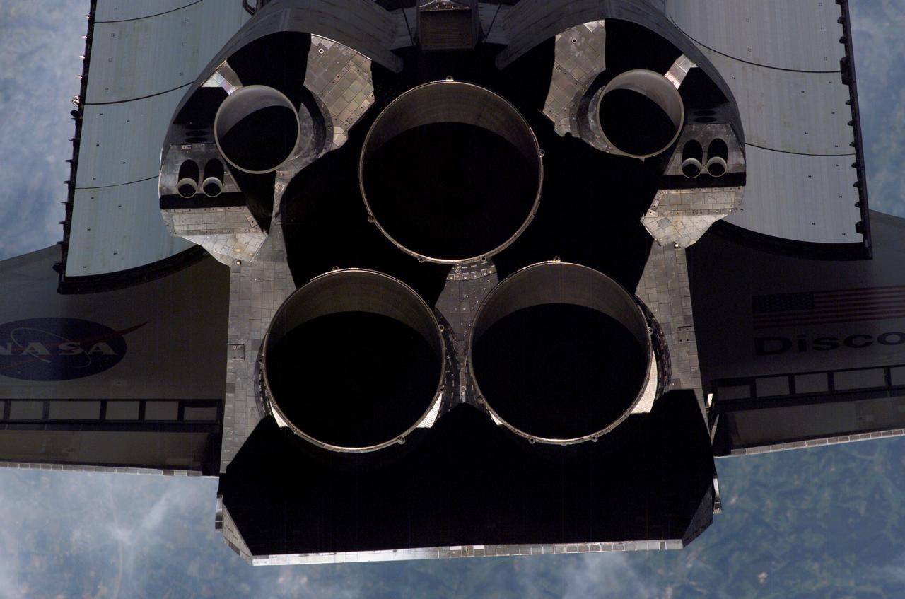
ISS013-E-47629 (6 July 2006) --- A close-up view of Space Shuttle Discovery's tail section is featured in this image photographed by an Expedition 13 crewmember on the International Space Station during STS-121 R-Pitch Maneuver survey on Flight Day 3. Visible are the shuttle's main engines, vertical stabilizer, orbital maneuvering system (OMS) pods, reaction control system (RCS) jets and a portion of payload bay door radiator and wings.
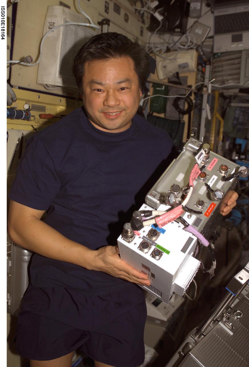
ISS010-E-18164 (17 February 2005) --- Astronaut Leroy Chiao, Expedition 10 commander and NASA ISS science officer, holds an Electronic Box Assembly, and Violation Isolation and Stabilization (VIS) Controller Assembly, which is part of the Treadmill Vibration Isolation System (TVIS) in the Zvezda Service Module of the International Space Station (ISS). Also in view is a VIS/TM data cable and VIS/TM power cable. This box receives power and distributes it between the treadmill and the VIS subassemblies.
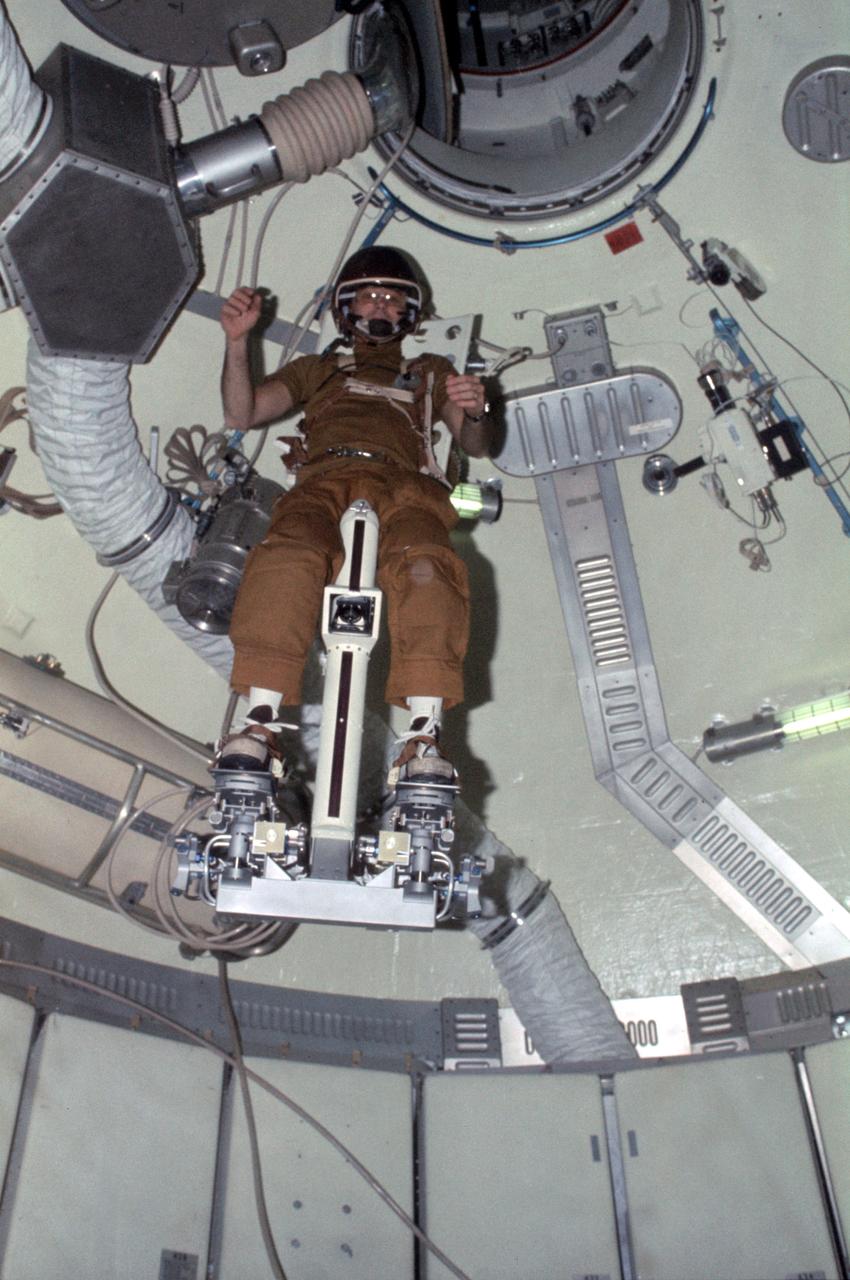
SL3-108-1304 (July-September 1973) --- Astronaut Alan L. Bean, Skylab 3 commander, flies the M509 Astronaut Maneuvering Equipment in the forward dome area of the Orbital Workshop (OWS) on the space station cluster in Earth orbit. Bean is strapped in to the back-mounted, hand-controlled Automatically Stabilized Maneuvering Unit (ASMU). This ASMU experiment is being done in shirt sleeves. The dome area where the experiment is conducted is about 22 feet in diameter and 19 feet from top to bottom. Photo credit: NASA
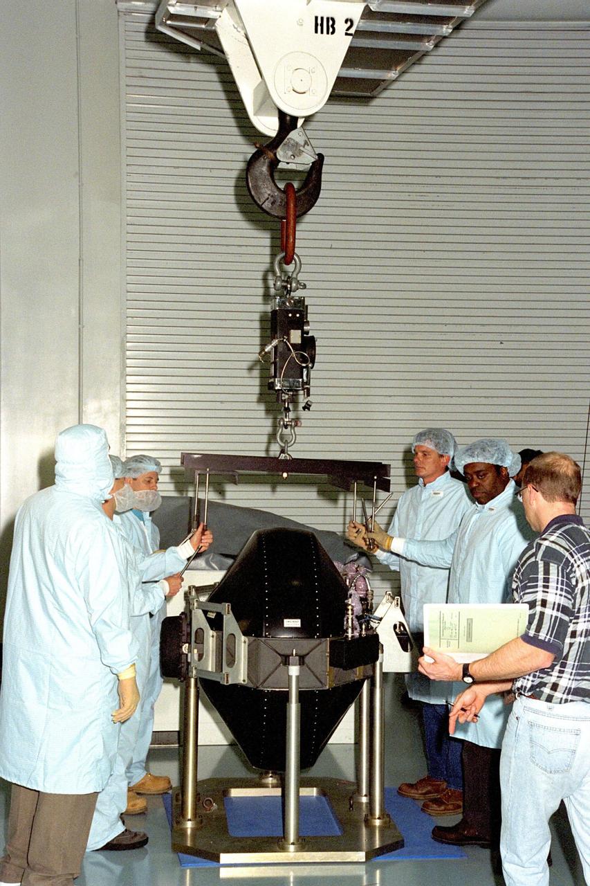
KENNEDY SPACE CENTER, FLA. -- A control moment gyro (CMG) is processed in KSC's Space Station Processing Facility. This gyro is one of four CMGs that will stabilize the International Space Station (ISS) while on orbit. The four gyros will connect with the Z-1 truss that is scheduled to launch on the third ISS flight, scheduled to occur aboard the Space Shuttle Atlantis on STS-92.
Boeing technicians move a Control Moment Gyroscope (CMG) to the Integrated Truss Structure (ITS) Z1 in the Space Station Processing Facility at KSC. Gyroscopes are used for stabilization of the International Space Station (ISS). The CMG and Z1, part of the construction of the ISS, will be carried on STS-92, the third U.S. flight planned for on-orbit construction of the ISS. STS-92 is scheduled for liftoff on June 17, 1999, aboard the Space Shuttle Atlantis
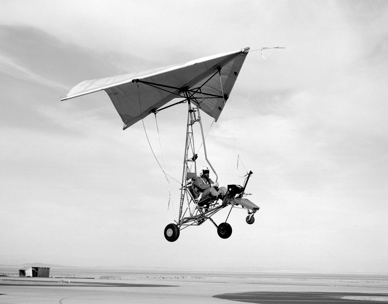
Pilot and Paresev 1 preparing for a landing on the Rogers dry lakebed in 1962 at Edwards Air Force Base, California. The flight program began with ground tow tests. Several tows were made before liftoff was attempted to check the control rigging and to familiarize the pilot with the vehicle’s ground stability. As the pilot’s confidence and experience increased, tow speeds were also increased until liftoff was attained. Liftoff was at about 40 knots indicated airspeed (kias).
Boeing technicians lower a Control Moment Gyroscope (CMG) into place on the Integrated Truss Structure (ITS) Z1 in the Space Station Processing Facility at KSC. Gyroscopes are used for stabilization of the International Space Station (ISS). The CMG and Z1, part of the construction of the ISS, will be carried on STS-92, the third U.S. flight planned for on-orbit construction of the ISS. STS-92 is scheduled for liftoff on June 17, 1999, aboard the Space Shuttle Atlantis
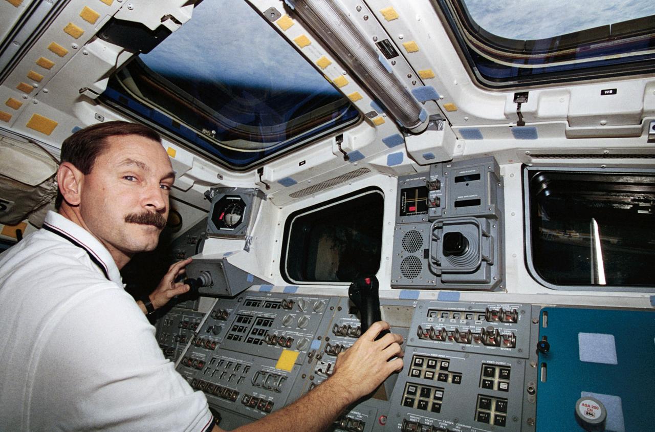
STS077-312-015 (19-29 May 1996) --- Astronaut Curtis L. Brown, Jr., pilot, mans the controls for the Remote Manipulator System (RMS) on the Space Shuttle Endeavour?s aft flight deck during rendezvous operations. During the flight, the six-member crew was involved in deployment and rendezvous operations with the Spartan 207/Inflatable Antenna Experiment (IAE) as well as the Passive Aerodynamically Stabilized Magnetically Damped Satellite (PAMS)/Satellite Test Unit (STU).
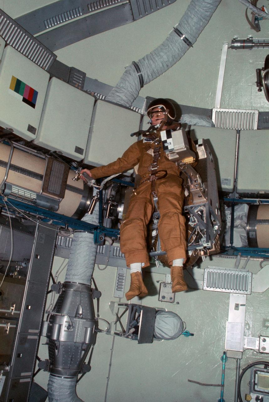
SL3-107-1215 (27 Aug. 1973) --- Astronaut Alan L. Bean, Skylab 3 commander, flies the M509 Astronaut Maneuvering Equipment in the forward dome area of the Orbital Workshop (OWS) on the space station cluster in Earth orbit. One of his fellow crewmen took this photograph with a 35mm Nikon camera. Bean is strapped into the back mounted, hand-controlled Automatically Stabilized Maneuvering Unit (ASMU). The dome area is about 22 feet in diameter and 19 feet from top to bottom. Photo credit: NASA
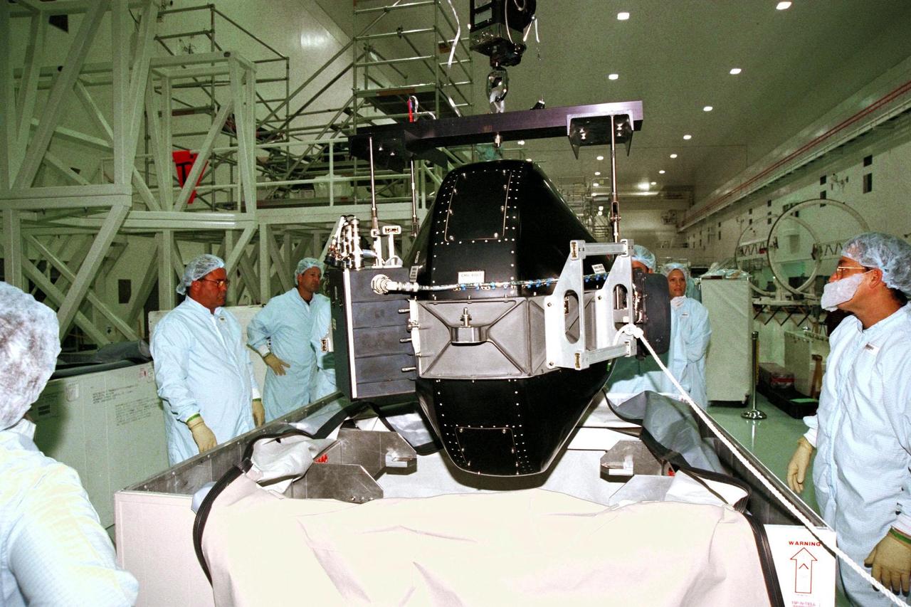
Boeing technicians remove the cover from a Control Moment Gyroscope (CMG) in the Space Station Processing Facility at KSC. The CMG will be attached to the Integrated Truss Structure (ITS) Z1. Gyroscopes are used for stabilization of the International Space Station (ISS). The CMG and Z1, part of the construction of the ISS, will be carried on STS-92, the third U.S. flight planned for on-orbit construction of the ISS. STS-92 is scheduled for liftoff on June 17, 1999, aboard the Space Shuttle Atlantis

51A-39-040 (14 Nov. 1984) --- A 70mm frame of Westar VI retrieval. Astronauts Dale A. Gardner, left, and Joseph P. Allen IV work together with Anna L. Fisher (not pictured, controlling remote manipulator system (RMS) arm from Discovery?s cabin) to bring Westar VI/PAM-D into cargo bay. Allen is on the mobile foot restraint, which is attached to the RMS end effector, while Gardner works to remove a stinger device from the now stabilized satellite. Photo credit: NASA
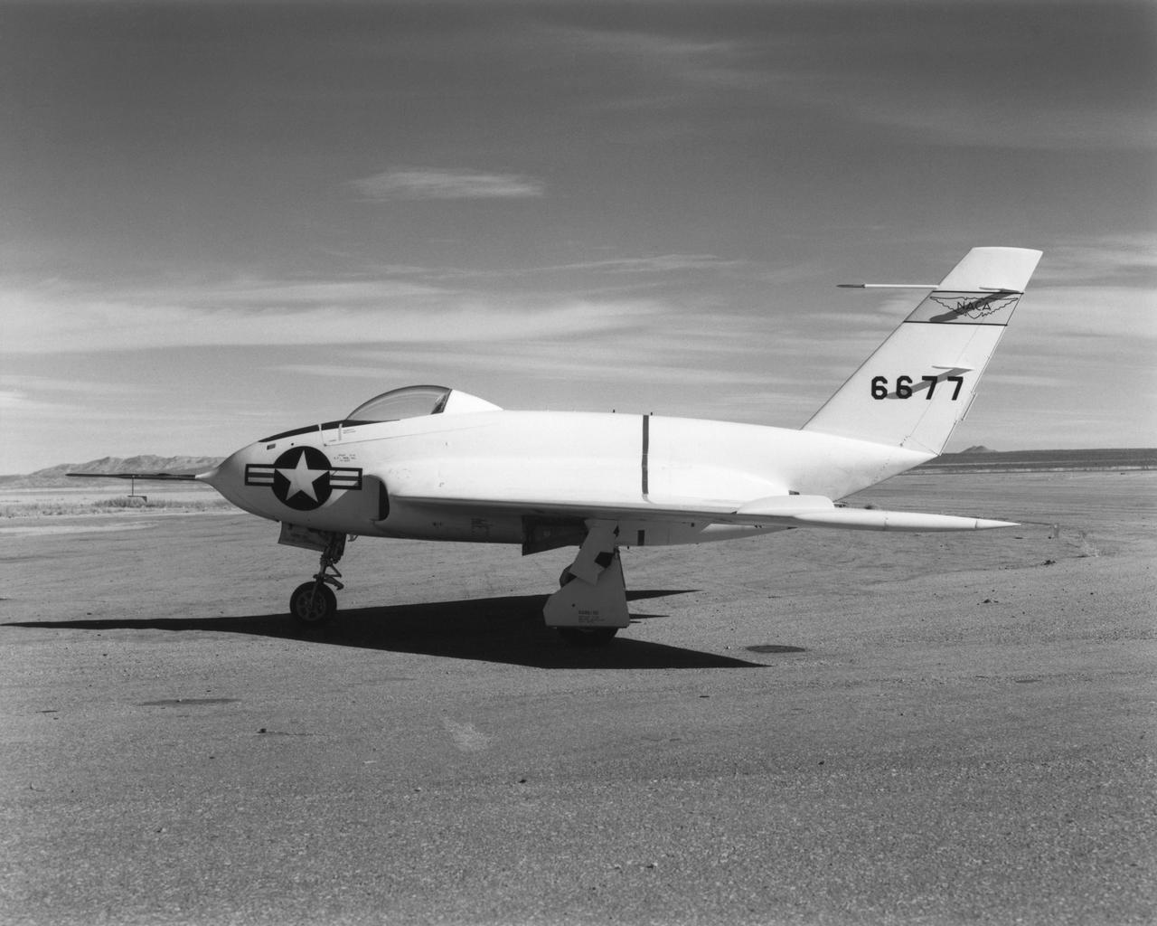
In this 1950 view of the left side of the NACA High-Speed Flight Research Station's X-4 research aircraft, the low swept wing and horizontal taillest design are seen. The X-4 Bantam, a single-place, low swept-wing, semi-tailless aircraft, was designed and built by Northrop Aircraft, Inc. It had no horizontal tail surfaces and its mission was to obtain in-flight data on the stability and control of semi-tailless aircraft at high subsonic speeds.
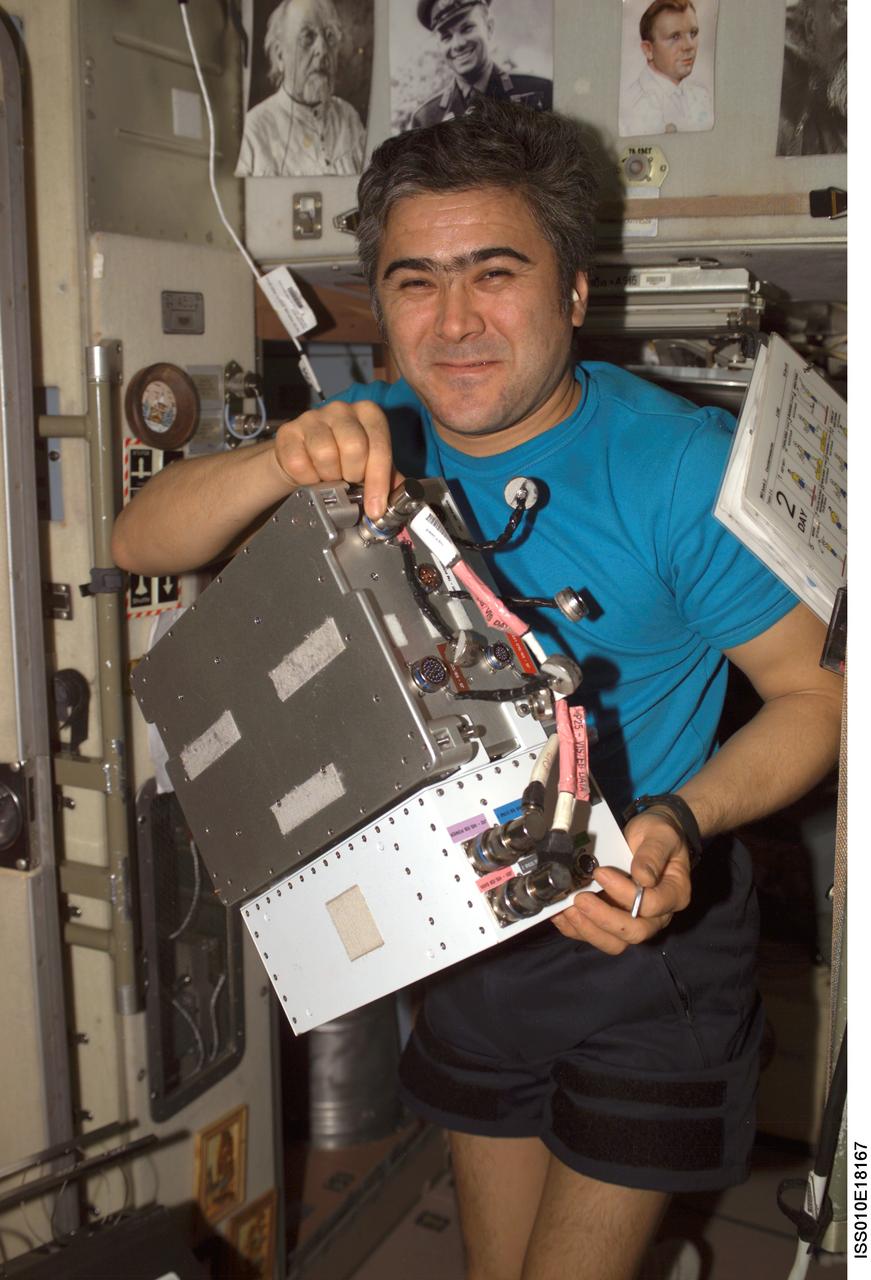
ISS010-E-18167 (17 February 2005) --- Cosmonaut Salizhan S. Sharipov, Expedition 10 flight engineer representing Russia's Federal Space Agency, holds an Electronic Box Assembly, and Violation Isolation and Stabilization (VIS) Controller Assembly, which is part of the Treadmill Vibration Isolation System (TVIS) in the Zvezda Service Module of the International Space Station (ISS). Also in view is a VIS/TM data cable and VIS/TM power cable. This box receives power and distributes it between the treadmill and the VIS subassemblies.
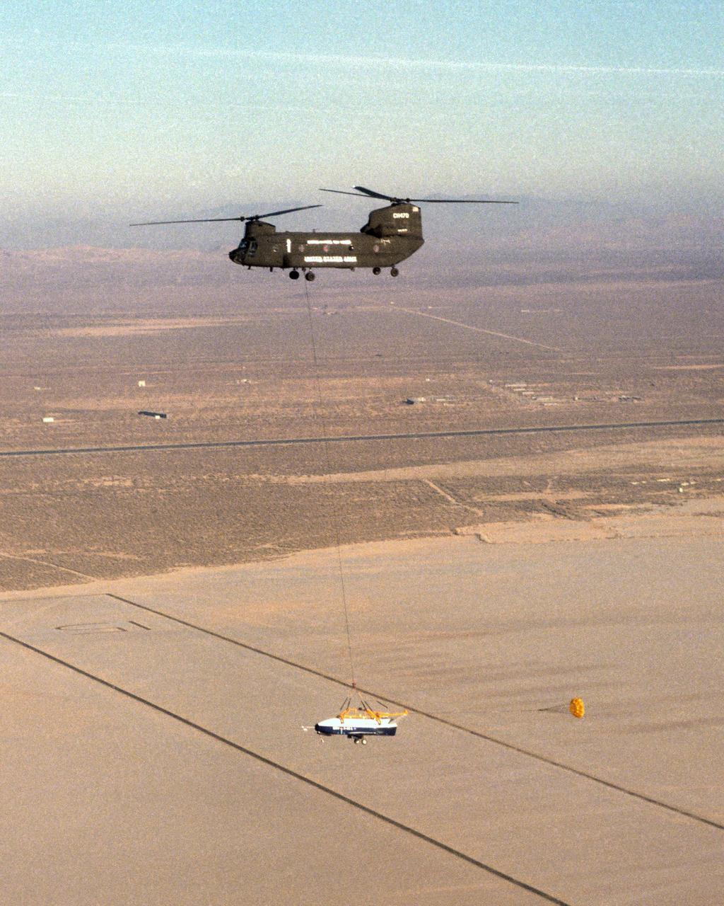
The X-40 sub-scale technology demonstrator and its U.S. Army CH-47 Chinook helicopter mothership fly over a dry lakebed runway during a captive-carry test flight from NASA's Dryden Flight Research Center, Edwards, California. The X-40 is attached to a sling which is suspended from the CH-47 by a 110-foot-long cable during the tests, while a small parachute trails behind to provide stability. The captive carry flights are designed to verify the X-40's navigation and control systems, rigging angles for its sling, and stability and control of the helicopter while carrying the X-40 on a tether. Following a series of captive-carry flights, the X-40 made free flights from a launch altitude of about 15,000 feet above ground, gliding to a fully autonomous landing. The X-40 is an unpowered 82 percent scale version of the X-37, a Boeing-developed spaceplane designed to demonstrate various advanced technologies for development of future lower-cost access to space vehicles.
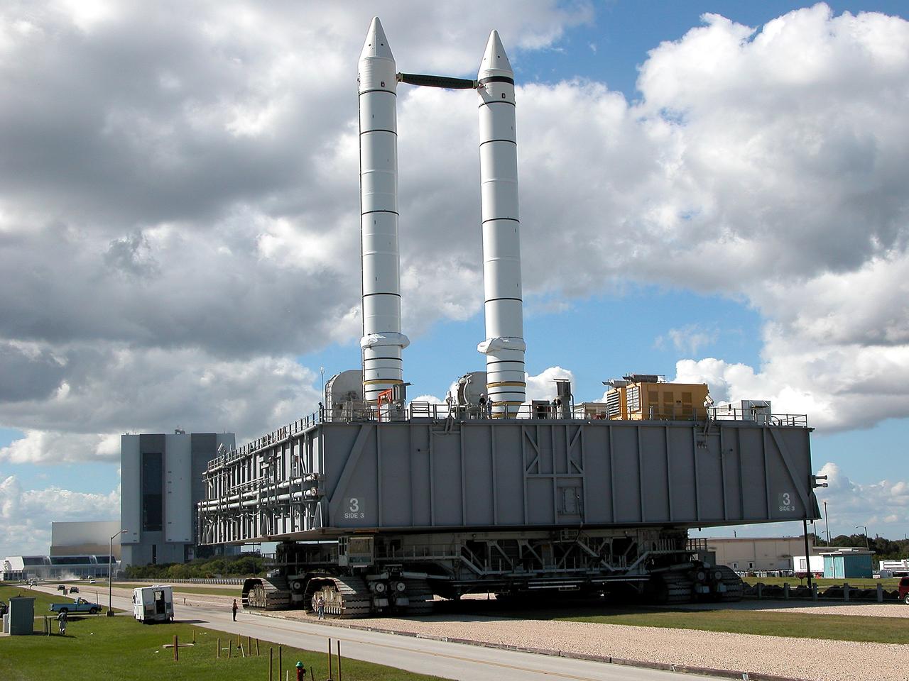
KENNEDY SPACE CENTER, FLA. - A crawler-transporter carrying Mobile Launcher Platform (MLP) number 3, with a set of twin solid rocket boosters bolted atop, crawls to the intersection in the crawlerway in support of the second engineering analysis vibration test on the crawler and MLP. From this perspective, the Launch Control Center (left) and the 525-foot-tall Vehicle Assembly Building (right) in the background appear dwarfed by the 184-foot-tall boosters. The crawler is moving at various speeds up to 1 mph in an effort to achieve vibration data gathering goals as it leaves the VAB, travels toward Launch Pad 39A and then returns. The boosters are braced at the top for stability. The primary purpose of these rollout tests is to gather data to develop future maintenance requirements on the transport equipment and the flight hardware. Various parts of the MLP and crawler transporter have been instrumented with vibration data collection equipment.
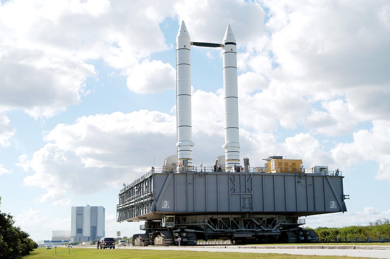
KENNEDY SPACE CENTER, FLA. - The crawler-transporter carrying Mobile Launcher Platform (MLP) number 3, with a set of twin solid rocket boosters bolted atop, crawls to the intersection in the crawlerway in support of the second engineering analysis vibration test on the crawler and MLP. From this perspective, the Launch Control Center (left) and the 525-foot-tall Vehicle Assembly Building (right) in the background appear dwarfed by the 184-foot-tall boosters. The crawler is moving at various speeds up to 1 mph in an effort to achieve vibration data gathering goals as it leaves the VAB, travels toward Launch Pad 39A and then returns. The boosters are braced at the top for stability. The primary purpose of these rollout tests is to gather data to develop future maintenance requirements on the transport equipment and the flight hardware. Various parts of the MLP and crawler transporter have been instrumented with vibration data collection equipment.
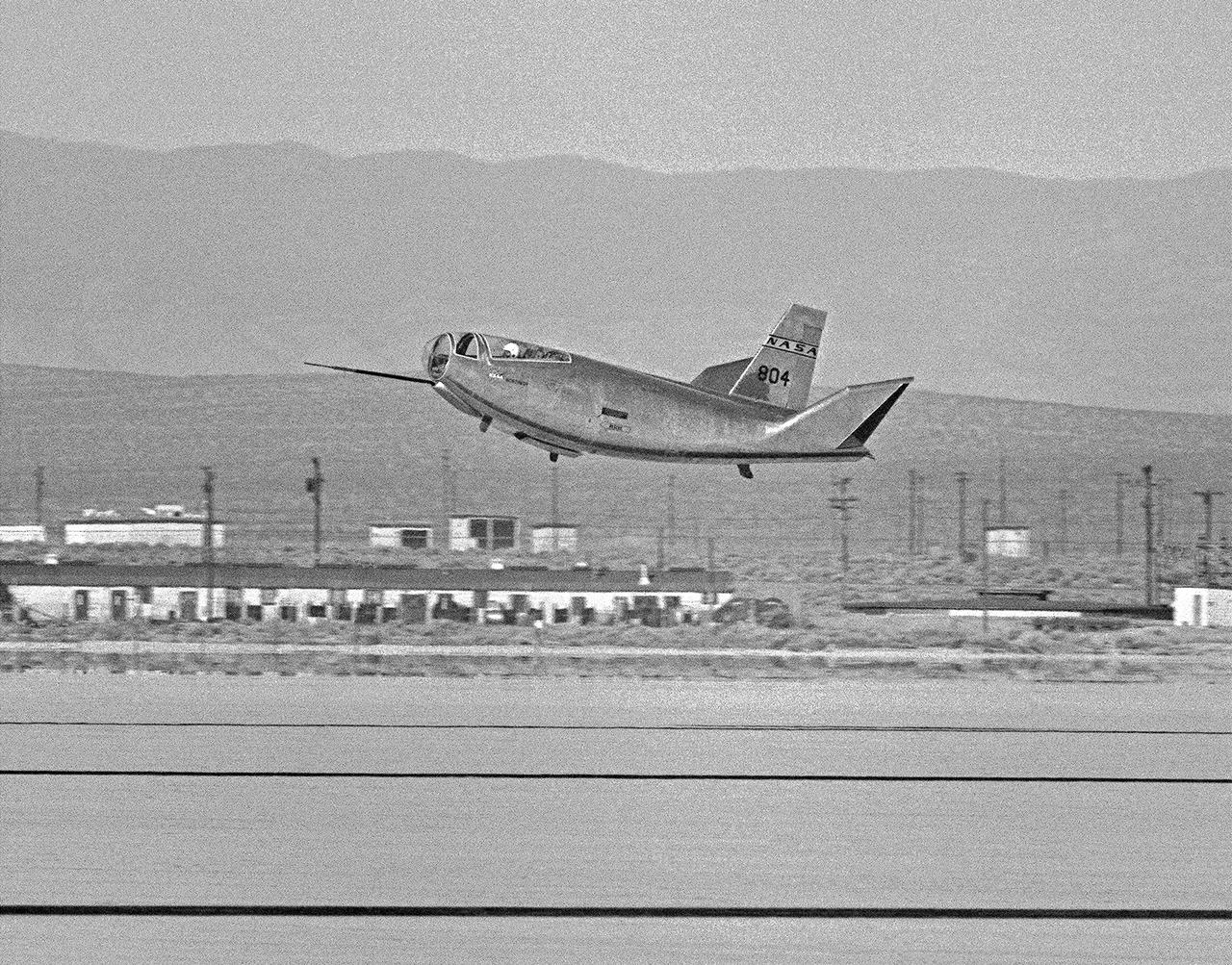
The HL-10 Lifting Body completes its first research flight with a landing on Rogers Dry Lake at Edwards AFB, California, on December 22, 1966. The HL-10 suffered from buffeting and poor control during the flight. Pilot Bruce Peterson was able to make a successful landing despite the severe problems. These were traced to airflow separation from the fins. As a result, the fins were no longer able to stabilize the vehicle. A small reshaping of the fins' leading edges cured the airflow separation, but it was not until March 15, 1968, that the second HL-10 flight occurred.
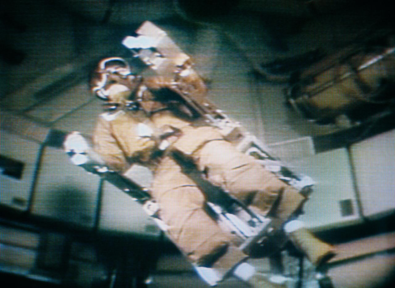
S73-34207 (28 Aug. 1973) --- Astronaut Alan L. Bean, Skylab 3 commander, flies the M509 astronaut Maneuvering Equipment, as seen in this photographic reproduction taken from a television transmission made by a color television camera in the Orbital Workshop (OWS) of the Skylab space station in Earth orbit. Bean is strapped into the back-mounted, hand-controlled Automatically Stabilized Maneuvering Unit (ASMU). The M509 exercise was in the forward dome area of the OWS. The dome area is about 22 feet in diameter and 19 feet from top to bottom. Photo credit: NASA
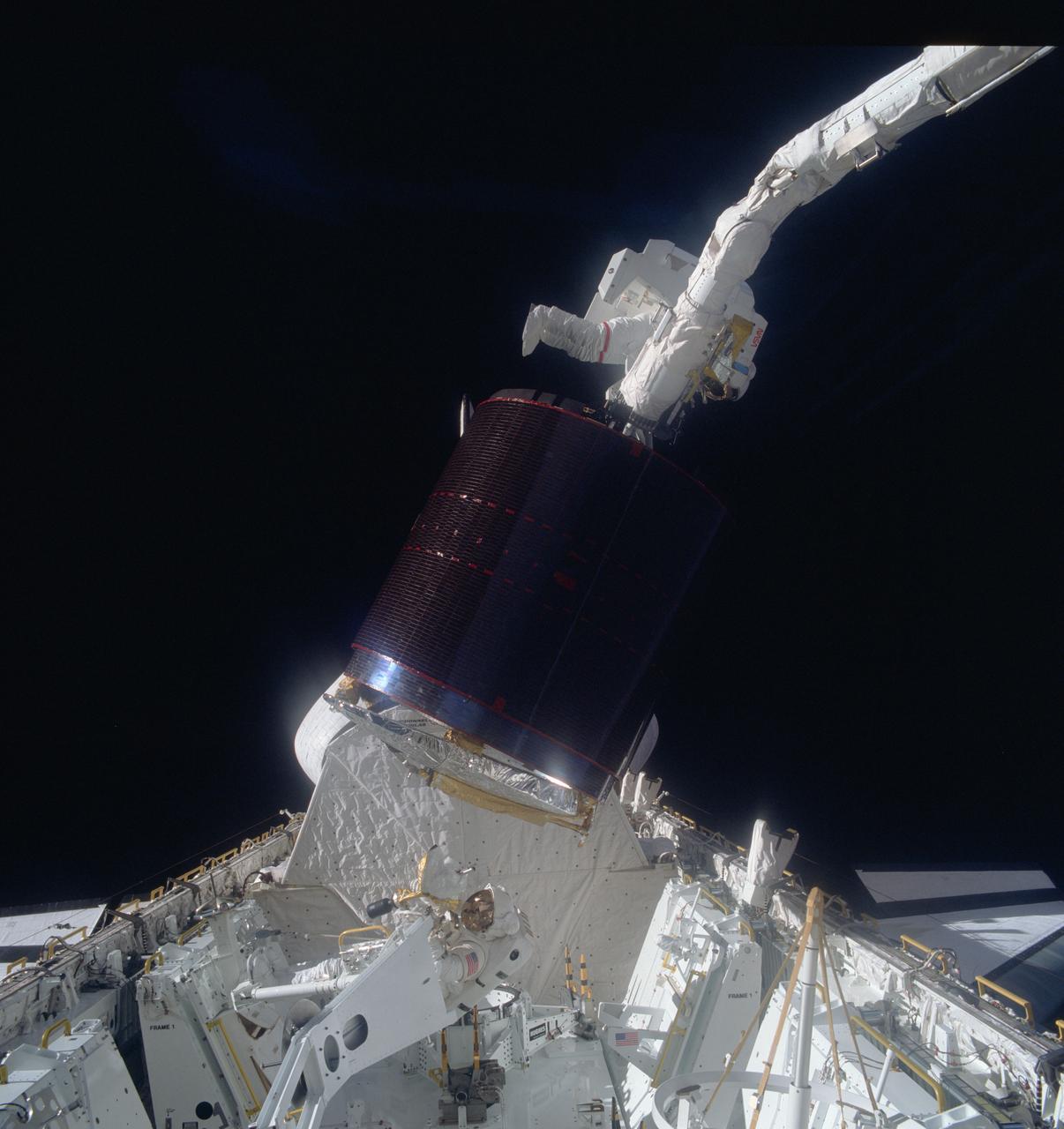
51A-41-021 (12 Nov 1984) --- Astronaut Joseph P. Allen IV, top, hangs onto a stinger device, which earlier had stabilized the pictured Palapa B-2 communications satellite, as astronaut Dale A. Gardner in the cargo bay of Discovery waits to assist in the berthing of the previously stranded spinning spacecraft. The end effector of the remote manipulatore system (RMS), controlled from inside Discovery's cabin by astronaut Anna L. Fisher, grasps a special grapple point to Allen's right. A fellow crewmember on the flight deck, using a 70mm handheld Hasselblad camera, exposed the frame. The activity took place on November 12, 1984.
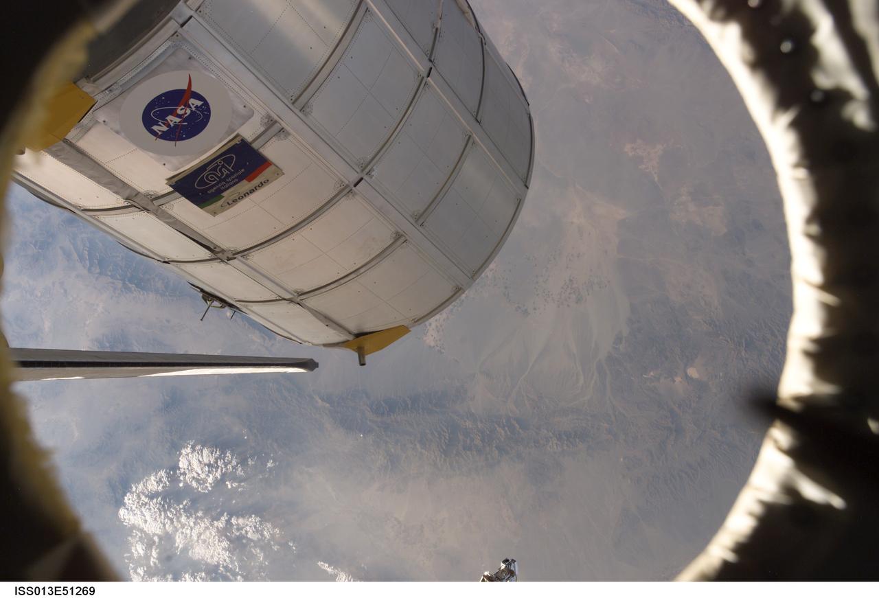
ISS013-E-51269 (14 July 2006) --- Canadarm2 or the Space Station Remote Manipulator System (SSRMS) arm (out of frame) grasps the Italian-built Multi-Purpose Logistics Module Leonardo to place it back in Discovery's cargo bay. On the other end of the arm, inside the shirt sleeve environment of the Destiny laboratory on the International Space Station, astronauts Stephanie D. Wilson and Lisa M. Nowak, STS-121 mission specialists, were in control of the transfer. The MPLM was being moved from its temporary parking place on the station's Unity node to the payload bay of Discovery for the return trip to Earth. Discovery's vertical stabilizer is at left.
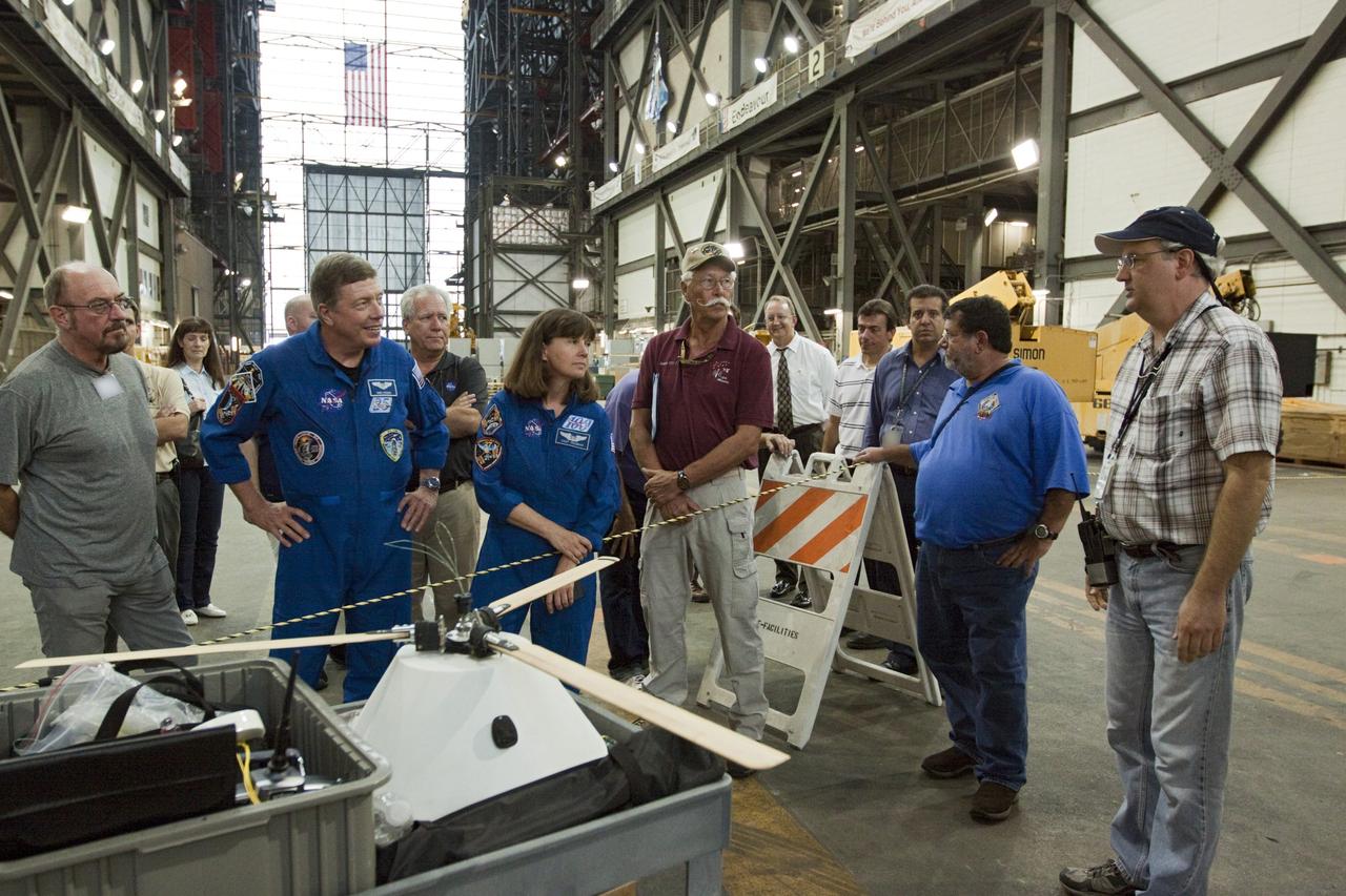
CAPE CANAVERAL, Fla. - Astronauts Mike Fossum and Cady Coleman, both in blue flight suits, look over the model capsule fit with rotor blades ahead of tests inside the Vehicle Assembly Building at NASA's Kennedy Space Center in Florida. NASA's Johnson Space Center Aerospace Engineer Jeff Hagen, right, fields questions about the project. The design would give a capsule the stability and control of a helicopter, but would not be powered. Instead, the wind passing over the rotors as the capsule descends would make the blades turn, a process called auto-rotation. The intent is to give real spacecraft a soft landing with enough control that they could touch down anywhere in the world, whether it be a runway or parking lot. In other words, wherever a helicopter could land, a spacecraft could land, too. Photo credit: NASA/Kim Shiflett
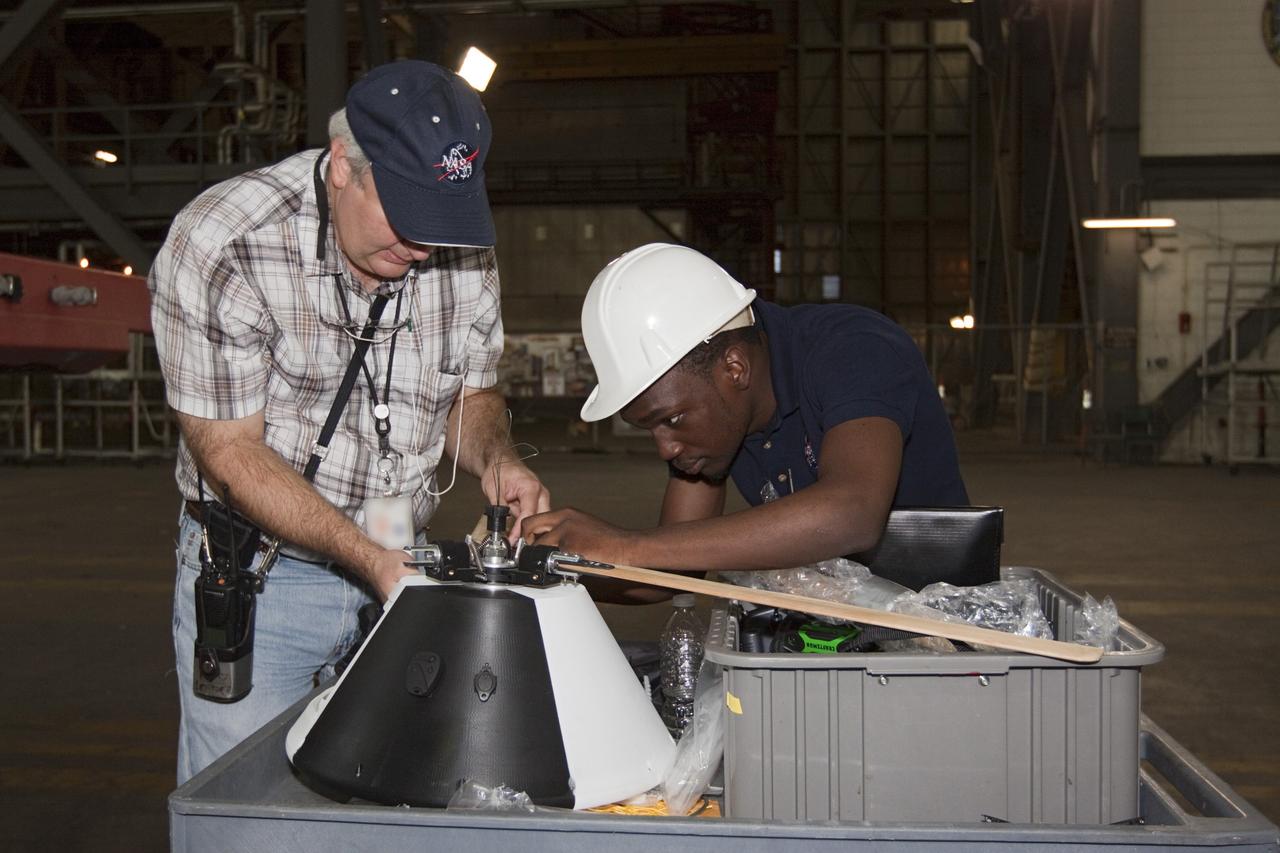
CAPE CANAVERAL, Fla. - NASA's Johnson Space Center Aerospace Engineer Jeff Hagen, left, and engineering intern Emmanuel Nyangweso attach rotors to the top of a model capsule ahead of tests inside the Vehicle Assembly Building at NASA's Kennedy Space Center in Florida. The design would give a capsule the stability and control of a helicopter, but would not be powered. Instead, the wind passing over the rotors as the capsule descends would make the blades turn, a process called auto-rotation. The intent is to give real spacecraft a soft landing with enough control that they could touch down anywhere in the world, whether it be a runway or parking lot. In other words, wherever a helicopter could land, a spacecraft could land, too. Photo credit: NASA/Kim Shiflett
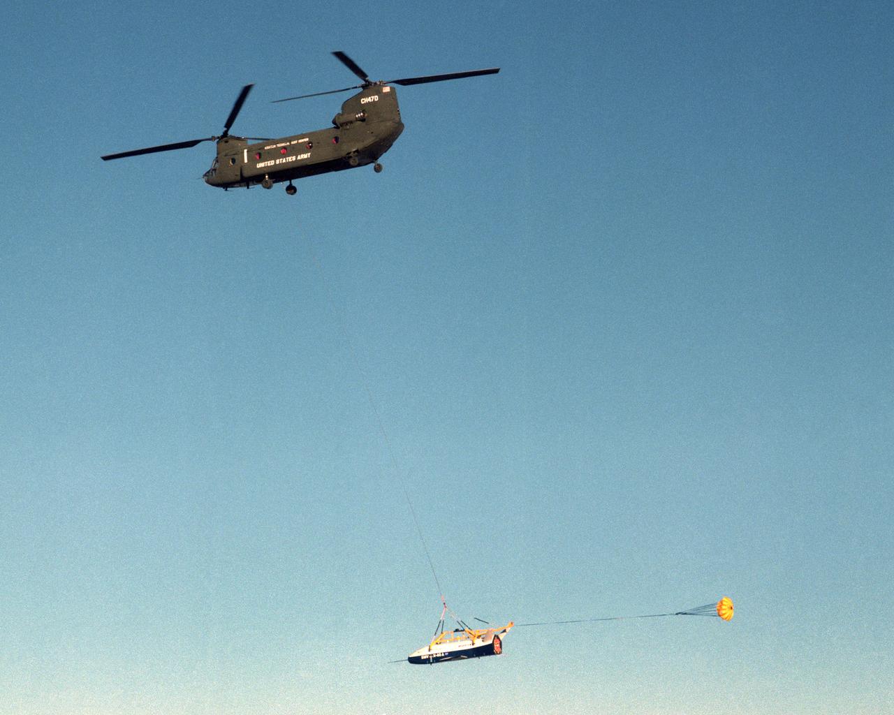
The X-40 sub-scale technology demonstrator is suspended under a U.S. Army CH-47 Chinook cargo helicopter during a captive-carry test flight at NASA's Dryden Flight Research Center, Edwards, California. The captive carry flights are designed to verify the X-40's navigation and control systems, rigging angles for its sling, and stability and control of the helicopter while carrying the X-40 on a tether. Following a series of captive-carry flights, the X-40 made free flights from a launch altitude of about 15,000 feet above ground, gliding to a fully autonomous landing. The X-40 is an unpowered 82 percent scale version of the X-37, a Boeing-developed spaceplane designed to demonstrate various advanced technologies for development of future lower-cost access to space vehicles.
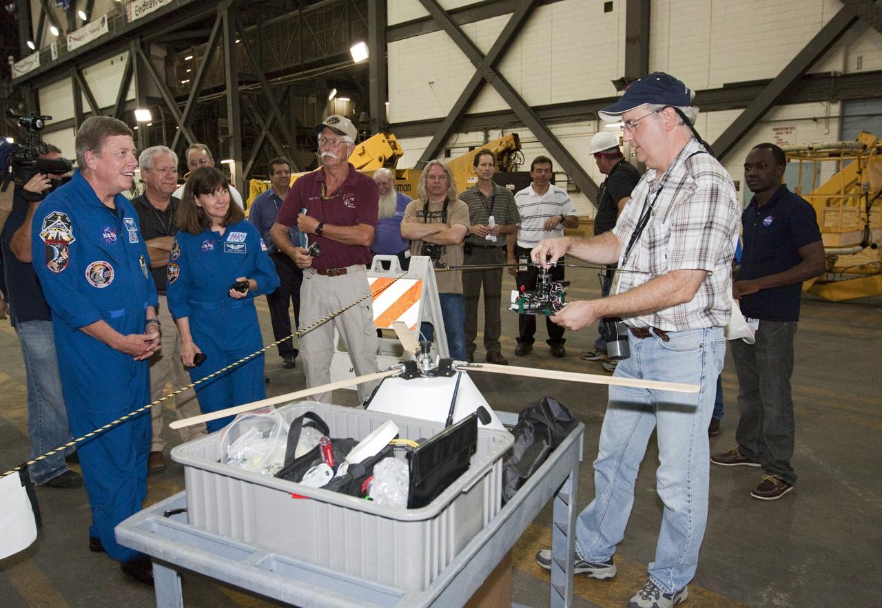
CAPE CANAVERAL, Fla. - Astronauts Mike Fossum and Cady Coleman, both in blue flight suits, listen as NASA's Johnson Space Center Aerospace Engineer Jeff Hagen explains the rotor mechanism for a model capsule ahead of tests inside the Vehicle Assembly Building at NASA's Kennedy Space Center in Florida. The design would give a capsule the stability and control of a helicopter, but would not be powered. Instead, the wind passing over the rotors as the capsule descends would make the blades turn, a process called auto-rotation. The intent is to give real spacecraft a soft landing with enough control that they could touch down anywhere in the world, whether it be a runway or parking lot. In other words, wherever a helicopter could land, a spacecraft could land, too. Photo credit: NASA/Kim Shiflett
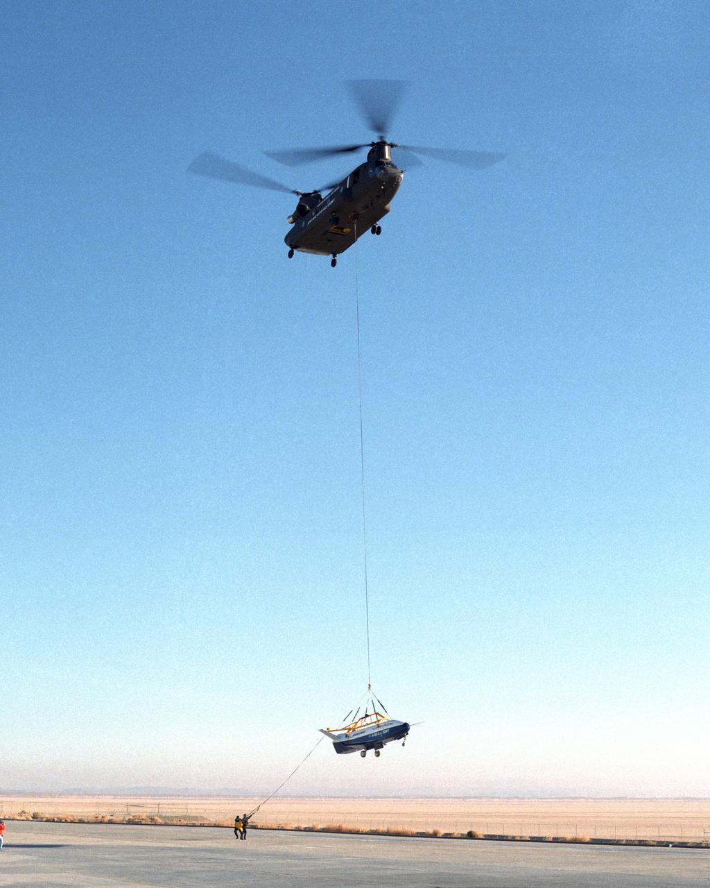
Ground crewmen help guide the alignment of the X-40 technology demonstrator as the experimental craft is gently lowered to the ground by a U.S. Army CH-47 Chinook cargo helicopter following a captive-carry test flight at NASA's Dryden Flight Research Center, Edwards, California. The X-40 is an unpowered 82 percent scale version of the X-37, a Boeing-developed spaceplane designed to demonstrate various advanced technologies for development of future lower-cost access to space vehicles. The X-37 will be carried into space aboard a space shuttle and then released to perform various maneuvers and a controlled re-entry through the Earth's atmosphere to an airplane-style landing on a runway, controlled entirely by pre-programmed computer software. Following a series of captive-carry flights, the X-40 made several free flights from a launch altitude of about 15,000 feet above ground, gliding to a fully autonomous landing. The captive carry flights helped verify the X-40's navigation and control systems, rigging angles for its sling, and stability and control of the helicopter while carrying the X-40 on a tether.
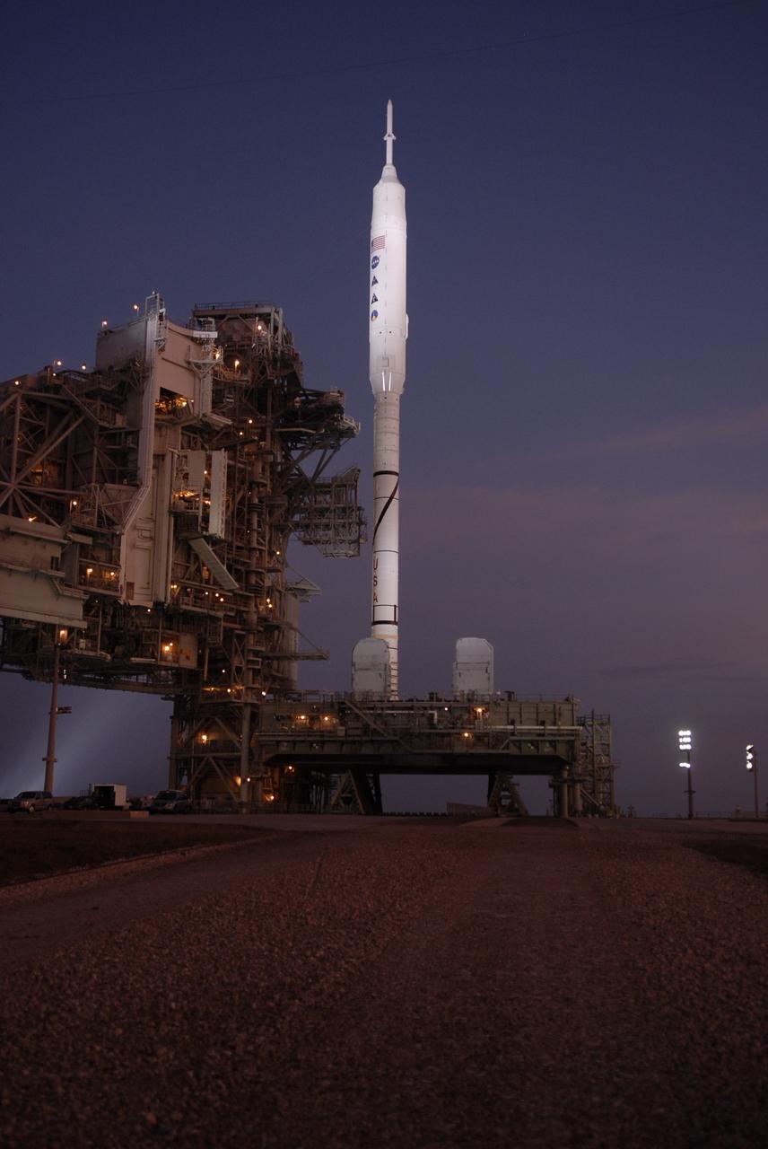
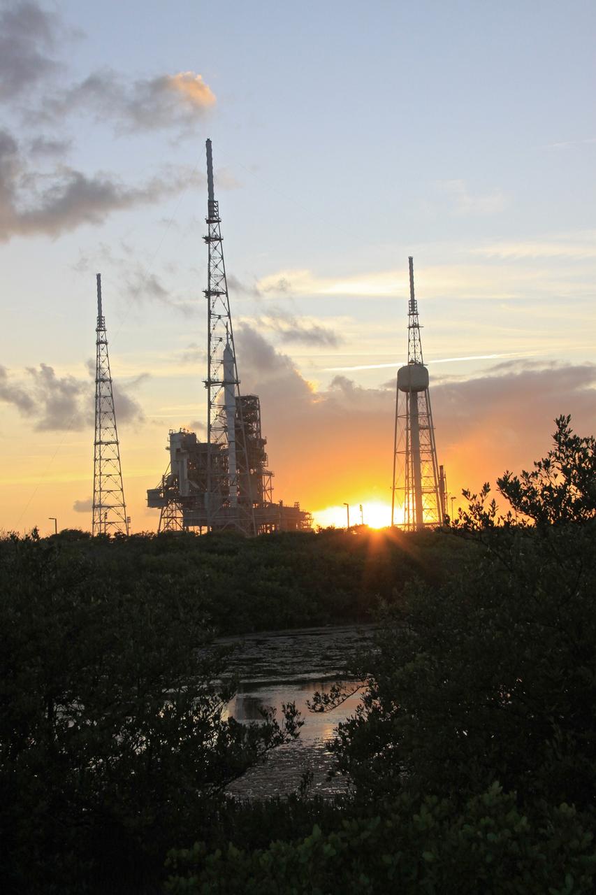
CAPE CANAVERAL, Fla. – Sunrise at Launch Pad 39B at NASA's Kennedy Space Center in Florida reveals the rotating service structure and the arms of the vehicle stabilization system have been retracted from around the Constellation Program's 327-foot-tall Ares I-X rocket for launch. The transfer of the pad from the Space Shuttle Program to the Constellation Program took place May 31. Modifications made to the pad include the removal of shuttle unique subsystems, such as the orbiter access arm and a section of the gaseous oxygen vent arm, and the installation of three 600-foot lightning towers, access platforms, environmental control systems and a vehicle stabilization system. The data returned from more than 700 sensors throughout the rocket will be used to refine the design of future launch vehicles and bring NASA one step closer to reaching its exploration goals. The Ares I-X flight test is targeted for Oct. 27. For information on the Ares I-X vehicle and flight test, visit http://www.nasa.gov/aresIX. Photo credit: NASA/Kim Shiflett

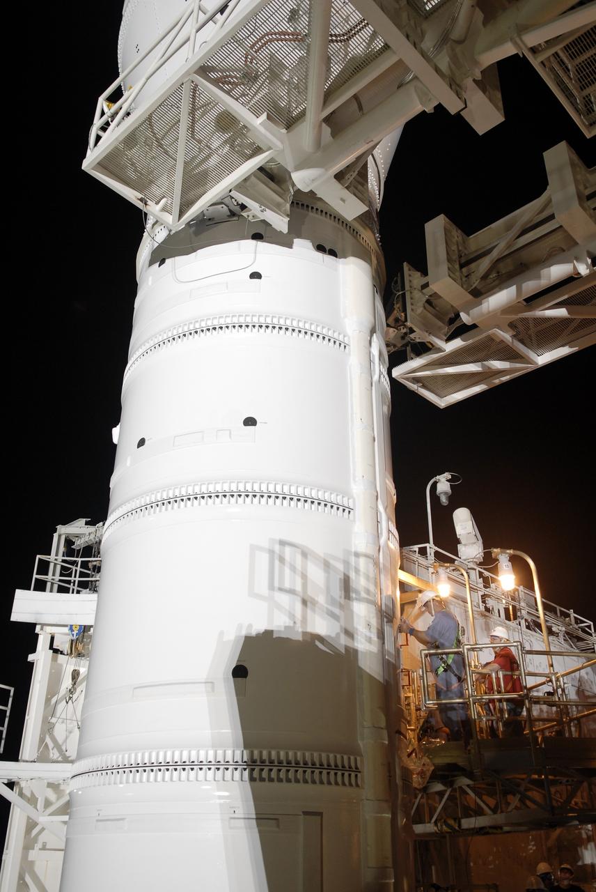
CAPE CANAVERAL, Fla. – Workers prepare to close the arms of the vehicle stabilization system around the towering 327-foot-tall Ares I-X rocket, newly arrived on Launch Pad 39B at NASA's Kennedy Space Center in Florida. The test rocket left the Vehicle Assembly Building at 1:39 a.m. EDT on its 4.2-mile trek to the pad and was "hard down" on the pad’s pedestals at 9:17 a.m. The transfer of the pad from the Space Shuttle Program to the Constellation Program took place May 31. Modifications made to the pad include the removal of shuttle unique subsystems, such as the orbiter access arm and a section of the gaseous oxygen vent arm, along with the installation of three 600-foot lightning towers, access platforms, environmental control systems and a vehicle stabilization system. Part of the Constellation Program, the Ares I-X is the test vehicle for the Ares I. The Ares I-X flight test is targeted for Oct. 27. For information on the Ares I-X vehicle and flight test, visit http://www.nasa.gov/aresIX. Photo credit: NASA/Kim Shiflett
CAPE CANAVERAL, Fla. – Workers on Launch Pad 39B at NASA's Kennedy Space Center in Florida prepare the Constellation Program's 327-foot-tall Ares I-X rocket for launch. The rotating service structure and the arms of the vehicle stabilization system will be moved from around the rocket for liftoff. The transfer of the pad from the Space Shuttle Program to the Constellation Program took place May 31. Modifications made to the pad include the removal of shuttle unique subsystems, such as the orbiter access arm and a section of the gaseous oxygen vent arm, and the installation of three 600-foot lightning towers, access platforms, environmental control systems and a vehicle stabilization system. The data returned from more than 700 sensors throughout the rocket will be used to refine the design of future launch vehicles and bring NASA one step closer to reaching its exploration goals. The Ares I-X flight test is targeted for Oct. 27. For information on the Ares I-X vehicle and flight test, visit http://www.nasa.gov/aresIX. Photo credit: NASA/Kim Shiflett
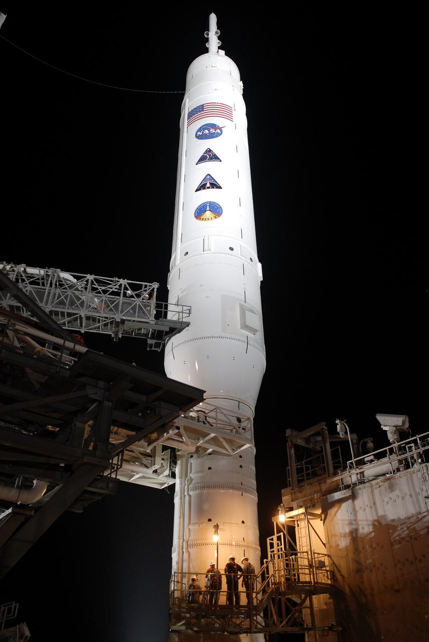
CAPE CANAVERAL, Fla. - Workers on Launch Pad 39B at NASA's Kennedy Space Center in Florida make final preparations for launch of the Constellation Program's 327-foot-tall Ares I-X rocket. The rotating service structure and the arms of the vehicle stabilization system will be moved from around the rocket for liftoff. The transfer of the pad from the Space Shuttle Program to the Constellation Program took place May 31. Modifications made to the pad include the removal of shuttle unique subsystems, such as the orbiter access arm and a section of the gaseous oxygen vent arm, and the installation of three 600-foot lightning towers, access platforms, environmental control systems and a vehicle stabilization system. The data returned from more than 700 sensors throughout the rocket will be used to refine the design of future launch vehicles and bring NASA one step closer to reaching its exploration goals. The Ares I-X flight test is targeted for Oct. 27. For information on the Ares I-X vehicle and flight test, visit http://www.nasa.gov/aresIX. Photo credit: NASA/Kim Shiflett
CAPE CANAVERAL, Fla. – The arms of the vehicle stabilization system are closed around the towering 327-foot-tall Ares I-X rocket, newly arrived on Launch Pad 39B at NASA's Kennedy Space Center in Florida. The test rocket left the Vehicle Assembly Building at 1:39 a.m. EDT on its 4.2-mile trek to the pad and was "hard down" on the pad’s pedestals at 9:17 a.m. The transfer of the pad from the Space Shuttle Program to the Constellation Program took place May 31. Modifications made to the pad include the removal of shuttle unique subsystems, such as the orbiter access arm and a section of the gaseous oxygen vent arm, along with the installation of three 600-foot lightning towers, access platforms, environmental control systems and a vehicle stabilization system. Part of the Constellation Program, the Ares I-X is the test vehicle for the Ares I. The Ares I-X flight test is targeted for Oct. 27. For information on the Ares I-X vehicle and flight test, visit http://www.nasa.gov/aresIX. Photo credit: NASA/Kim Shiflett
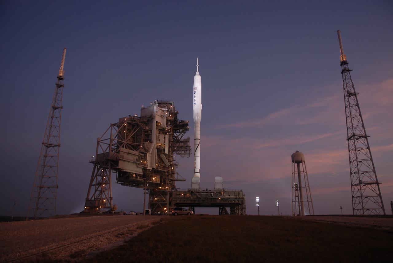
CAPE CANAVERAL, Fla. – As the sun rises over Launch Pad 39B at NASA's Kennedy Space Center in Florida, the rotating service structure and the arms of the vehicle stabilization system have been retracted from around the Constellation Program's 327-foot-tall Ares I-X rocket, resting atop its mobile launcher platform, for launch. The transfer of the pad from the Space Shuttle Program to the Constellation Program took place May 31. Modifications made to the pad include the removal of shuttle unique subsystems, such as the orbiter access arm and a section of the gaseous oxygen vent arm, and the installation of three 600-foot lightning towers, access platforms, environmental control systems and a vehicle stabilization system. The data returned from more than 700 sensors throughout the rocket will be used to refine the design of future launch vehicles and bring NASA one step closer to reaching its exploration goals. The Ares I-X flight test is targeted for Oct. 27. For information on the Ares I-X vehicle and flight test, visit http://www.nasa.gov/aresIX. Photo credit: NASA/Kim Shiflett
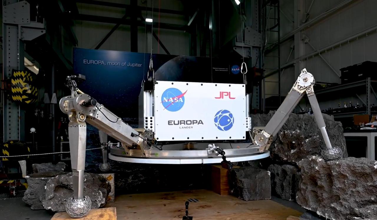
On Aug. 17 and 18, 2023, engineers at NASA's Jet Propulsion Laboratory in Southern California tested the landing system for a proposed future mission that would touch down on Jupiter's icy moon Europa. This system for the proposed Europa Lander is an evolution of hardware used on previous NASA lander missions. It includes the architecture used for the "sky crane maneuver" that helped lower NASA's Curiosity and Perseverance rovers onto the Martian surface, which would give the lander the stability it needs during touchdown. Although this landing architecture was developed with Europa as the target, it could be adapted for use at other moons and celestial bodies with challenging terrain. Four bridles, suspended from an overhead simulated propulsive descent stage, maintain a level lander body. The four legs conform passively to the terrain they encounter as the lander body continues to descend toward the surface. Each leg consists of a four-bar linkage mechanism that controls the leg's pose before and during landing. The legs are preloaded downward with a constant force spring to help them rearrange and compress the surface they encounter prior to landing, giving them extra traction and stability during and after the landing event. Acting like a skid plate, the belly pan provides the underside of the spacecraft with protection from potentially harmful terrain. The belly pan also resists shear motion on the terrain it interacts with. Once the belly pan contacts the surface, sensors trigger a mechanism that quickly locks the legs' "hip" and "knee" rotary joints, resulting in a table-like stance. At this point, the job of ensuring lander stability shifts from the bridles to the legs. This shift keeps the lander level after the bridles are unloaded. In the event the belly pan does not encounter terrain during the touchdown process, sensors in each leg can also declare touchdown. After the leg joints lock, the belly pan would be suspended above the landed terrain, and the lander would be supported only by the four legs. Not pictured in the video is the period after the bridles are offloaded and flyaway is commanded. The bridles would then be cut, and the hovering propulsive stage would fly away, leaving the lander in a stable stance on the surface. Movie available at https://photojournal.jpl.nasa.gov/catalog/PIA26010

KENNEDY SPACE CENTER, FLA. -- Swordtail fish (Xiphophorus helleri), like those that are part of the Neurolab payload on Space Shuttle Mission STS-90, are shown in their holding tank in the Operations and Checkout Building. The fish will fly in the Closed Equilibrated Biological Aquatic System (CEBAS) Minimodule, a middeck locker-sized fresh water habitat, designed to allow the controlled incubation of aquatic species in a self-stabilizing, artifical ecosystem for up to three weeks under space conditions. Investigations during the Neurolab mission will focus on the effects of microgravity on the nervous system. The crew of STS-90, slated for launch April 16 at 2:19 p.m. EDT, include Commander Richard Searfoss, Pilot Scott Altman, Mission Specialists Richard Linnehan, D.V.M., Dafydd (Dave) Williams, M.D., and Kathryn (Kay) Hire, and Payload Specialists Jay Buckey, M.D., and James Pawelczyk, Ph.D
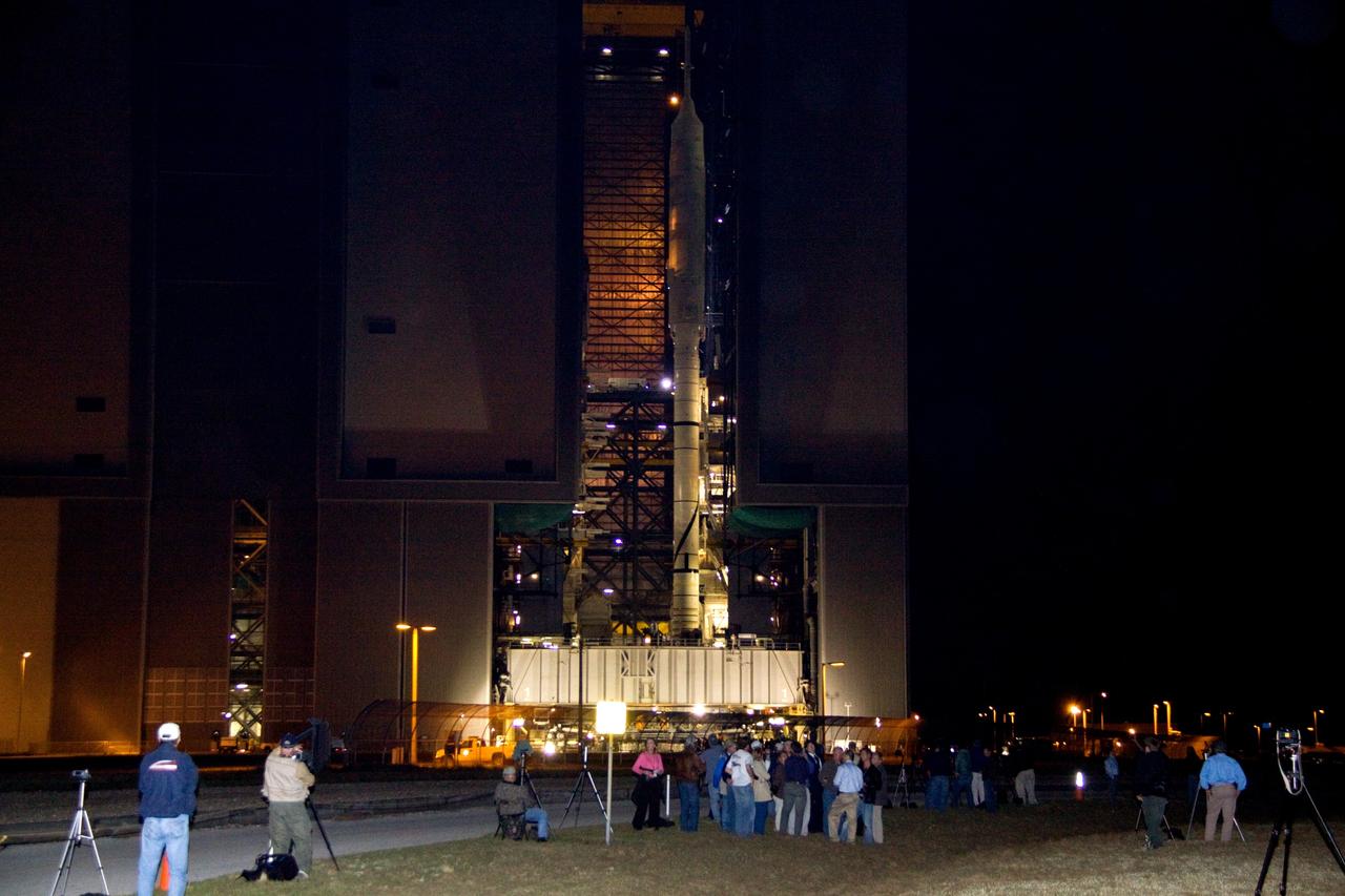
CAPE CANAVERAL, Fla. – Outside the massive Vehicle Assembly Building at NASA's Kennedy Space Center in Florida, members of the news media (foreground) wait in the dark for the rollout of the Ares I-X to begin. The rocket will travel the 4.2 miles to Launch Pad 39B atop the crawler-transporter. The transfer of the pad from the Space Shuttle Program to the Constellation Program took place May 31. Modifications made to the pad include the removal of shuttle unique subsystems, such as the orbiter access arm and a section of the gaseous oxygen vent arm, along with the installation of three 600-foot lightning towers, access platforms, environmental control systems and a vehicle stabilization system. Part of the Constellation Program, the Ares I-X is the test vehicle for the Ares I. The Ares I-X flight test is targeted for Oct. 27. For information on the Ares I-X vehicle and flight test, visit http://www.nasa.gov/aresIX. Photo credit: NASA/Jack Pfaller

KENNEDY SPACE CENTER, FLA. -- United Space Alliance workers on board the Freedom Star, one of the Shuttle Rocket Booster retrieval ships, check the controls on the recompression chamber at right. The ship and its dive team, including a diver medical technician, Andy Fish, were instrumental in rescuing a lobster diver in distress off Cape Canaveral Sept. 11. The ship was on a certification exercise and near the location of a lobster diving boat that radioed the U.S. Coast Guard for help when one of the divers experienced difficulty breathing on his return to the surface. Hearing the call for help, the captain of the Freedom Star offered to help. Fish stayed with the diver in the recompression chamber aboard the Freedom Star until the ship reached Port Canaveral where a KSC Occupational Health doctor waited. The diver was stabilized and taken to Florida Hospital.
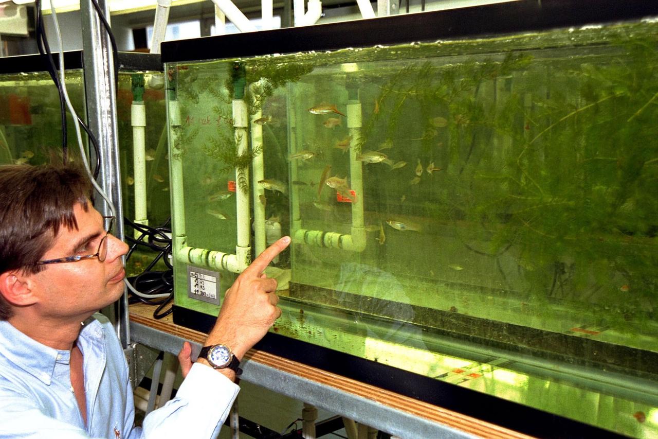
KENNEDY SPACE CENTER, FLA. -- Dr. Dirk Voeste, a scientist with Ruhr-University of Bochum, Germany, examines some swordtail fish (Xiphophorus helleri), like those that are part of the Neurolab payload on Space Shuttle Mission STS-90, in their holding tank in the Operations and Checkout Building. The fish will fly in the Closed Equilibrated Biological Aquatic System (CEBAS) Minimodule, a middeck locker-sized fresh water habitat, designed to allow the controlled incubation of aquatic species in a self-stabilizing, artifical ecosystem for up to three weeks under space conditions. Investigations during the Neurolab mission will focus on the effects of microgravity on the nervous system. The crew of STS-90, slated for launch April 16 at 2:19 p.m. EDT, include Commander Richard Searfoss, Pilot Scott Altman, Mission Specialists Richard Linnehan, D.V.M., Dafydd (Dave) Williams, M.D., and Kathryn (Kay) Hire, and Payload Specialists Jay Buckey, M.D., and James Pawelczyk, Ph.D
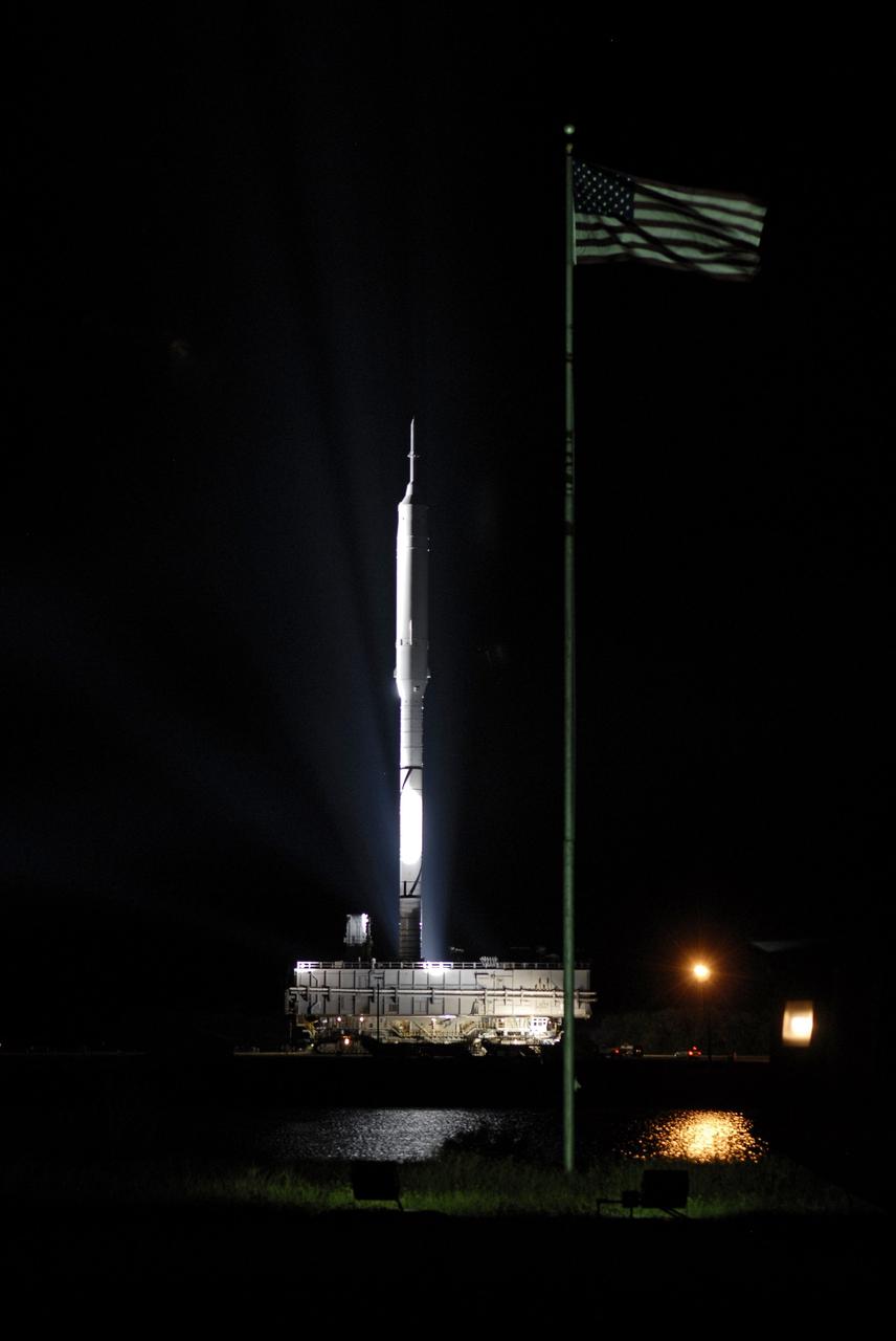
CAPE CANAVERAL, Fla. - The American flag waves as the Ares I-X rocket passes by on its slow trek to Launch Pad 39B at NASA's Kennedy Space Center in Florida. The rocket, riding atop a crawler-transporter, began the 4.2-mile journey at 1:39 a.m. EDT. The transfer of the pad from the Space Shuttle Program to the Constellation Program took place May 31. Modifications made to the pad include the removal of shuttle unique subsystems, such as the orbiter access arm and a section of the gaseous oxygen vent arm, along with the installation of three 600-foot lightning towers, access platforms, environmental control systems and a vehicle stabilization system. Part of the Constellation Program, the Ares I-X is the test vehicle for the Ares I. The Ares I-X flight test is targeted for Oct. 27. For information on the Ares I-X vehicle and flight test, visit http://www.nasa.gov/aresIX. Photo credit: NASA/Kim Shiflett
CAPE CANAVERAL, Fla. - The Ares I-X rocket heads toward Launch Pad 39B at NASA's Kennedy Space Center in Florida, riding atop a crawler-transporter. The 4.2-mile trip to the pad from the massive Vehicle Assembly Building began at 1:39 a.m. EDT. The transfer of the pad from the Space Shuttle Program to the Constellation Program took place May 31. Modifications made to the pad include the removal of shuttle unique subsystems, such as the orbiter access arm and a section of the gaseous oxygen vent arm, along with the installation of three 600-foot lightning towers, access platforms, environmental control systems and a vehicle stabilization system. Part of the Constellation Program, the Ares I-X is the test vehicle for the Ares I. The Ares I-X flight test is targeted for Oct. 27. For information on the Ares I-X vehicle and flight test, visit http://www.nasa.gov/aresIX. Photo credit: NASA/Kim Shiflett
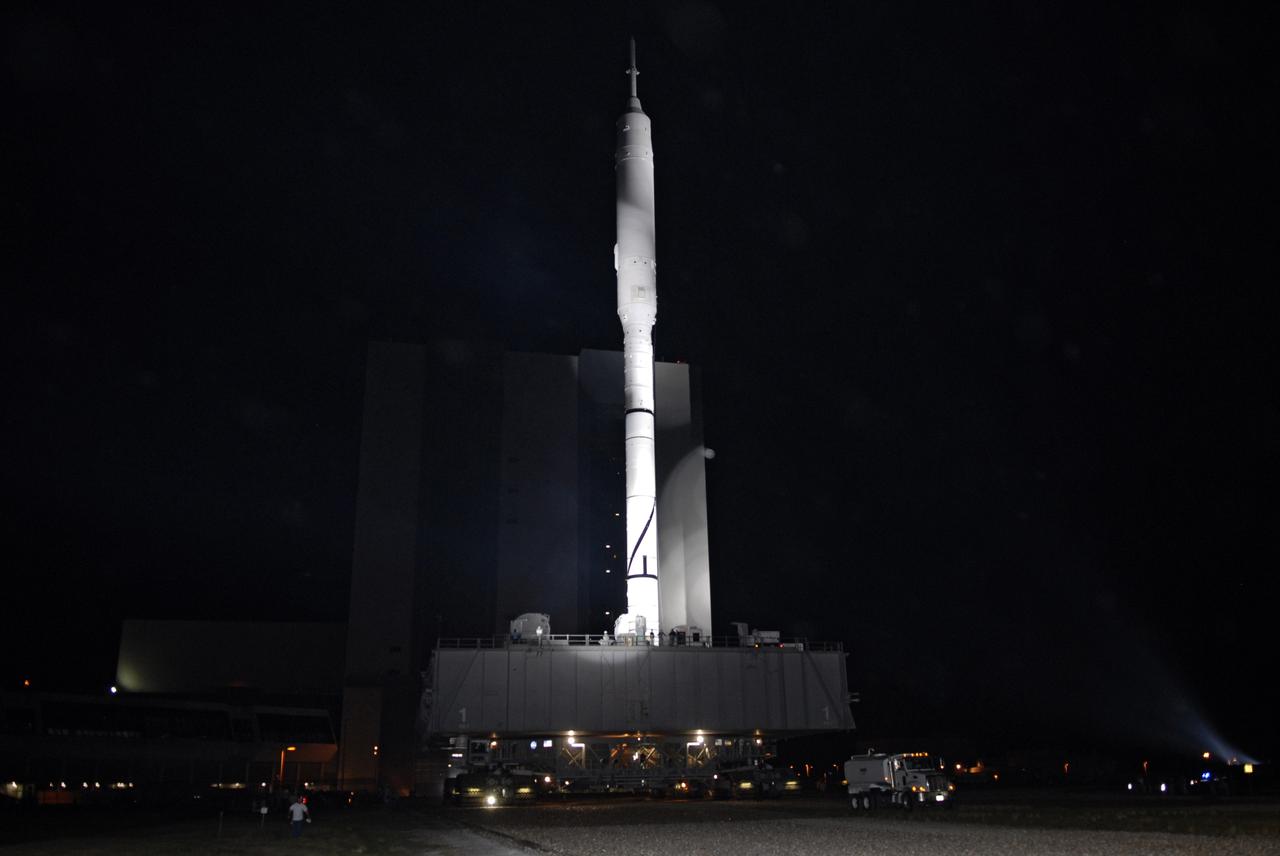
CAPE CANAVERAL, Fla. - The towering 327-foot-tall Ares I-X rocket moves away from the Vehicle Assembly Building at NASA's Kennedy Space Center in Florida. The rocket's slow, 4.2-mile journey to Launch Pad 39B began at 1:39 a.m. EDT. The transfer of the pad from the Space Shuttle Program to the Constellation Program took place May 31. Modifications made to the pad include the removal of shuttle unique subsystems, such as the orbiter access arm and a section of the gaseous oxygen vent arm, along with the installation of three 600-foot lightning towers, access platforms, environmental control systems and a vehicle stabilization system. Part of the Constellation Program, the Ares I-X is the test vehicle for the Ares I. The Ares I-X flight test is targeted for Oct. 27. For information on the Ares I-X vehicle and flight test, visit http://www.nasa.gov/aresIX. Photo credit: NASA/Kim Shiflett
CAPE CANAVERAL, Fla. – Standing tall, the Ares I-X rocket rides atop the crawler-transporter as it moves beyond the Vehicle Assembly Building at NASA's Kennedy Space Center in Florida. Its slow trek to Launch Pad 39B, known as "rollout," began at 1:39 a.m. EDT. The transfer of the pad from the Space Shuttle Program to the Constellation Program took place May 31. Modifications made to the pad include the removal of shuttle unique subsystems, such as the orbiter access arm and a section of the gaseous oxygen vent arm, along with the installation of three 600-foot lightning towers, access platforms, environmental control systems and a vehicle stabilization system. Part of the Constellation Program, the Ares I-X is the test vehicle for the Ares I. The Ares I-X flight test is targeted for Oct. 27. For information on the Ares I-X vehicle and flight test, visit http://www.nasa.gov/aresIX. Photo credit: NASA/Jim Grossmann
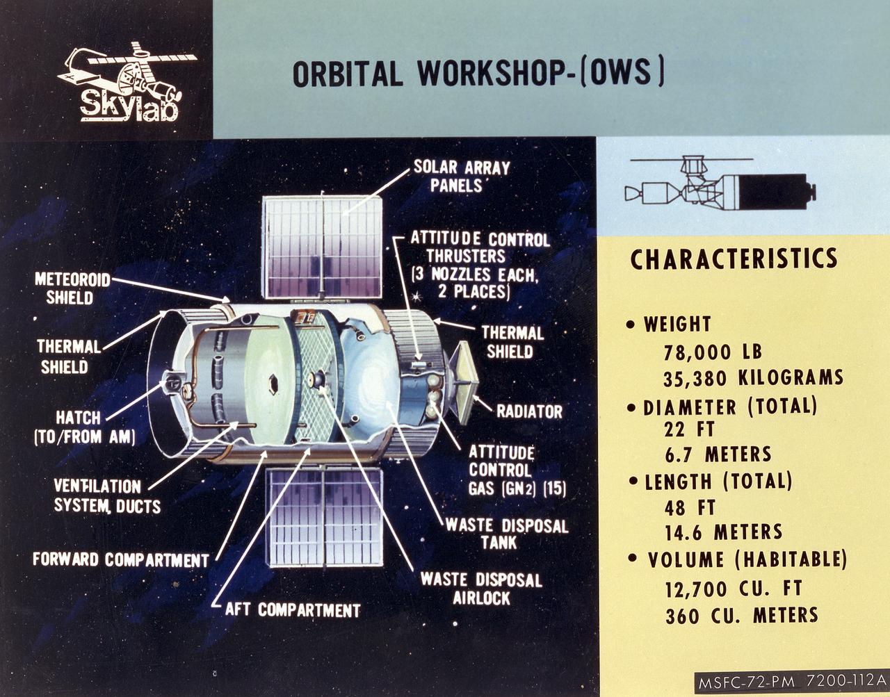
This cutaway illustration shows the characteristics and basic elements of the Skylab Orbiter Workshop (OWS). The OWS was divided into two major compartments. The lower level provided crew accommodations for sleeping, food preparation and consumption, hygiene, waste processing and disposal, and performance of certain experiments. The upper level consisted of a large work area and housed water storage tanks, a food freezer, storage vaults for film, scientific airlocks, mobility and stability experiment equipment, and other experimental equipment. The compartment below the crew quarters was a container for liquid and solid waste and trash accumulated throughout the mission. A solar array, consisting of two wings covered on one side with solar cells, was mounted outside the workshop to generate electrical power to augment the power generated by another solar array mounted on the solar observatory. Thrusters were provided at one end of the workshop for short-term control of the attitude of the space station.
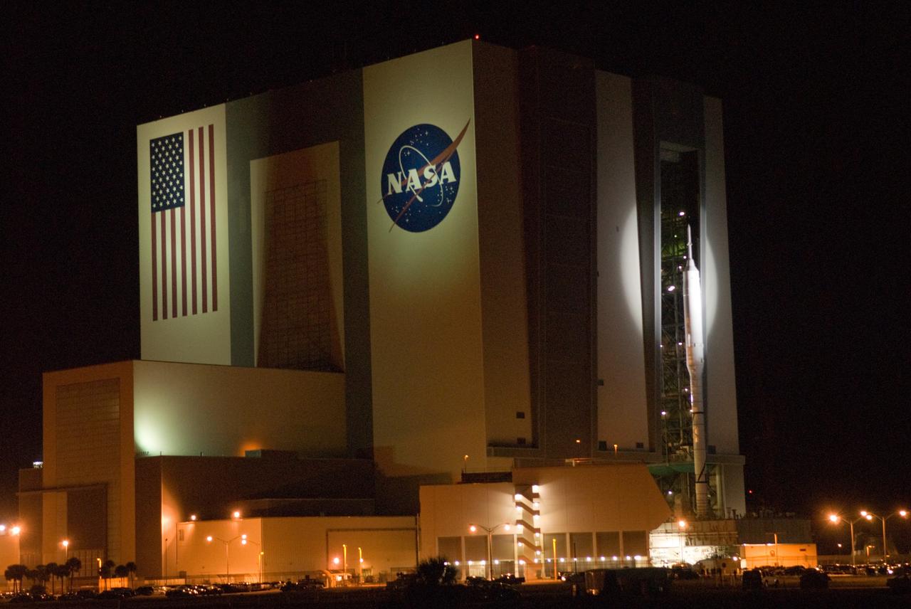
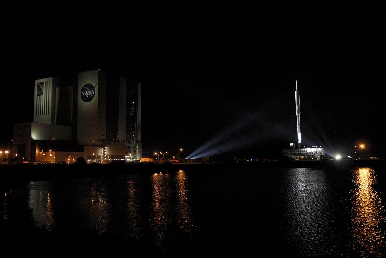
CAPE CANAVERAL, Fla. – Spotlighted against the Vehicle Assembly Building at NASA's Kennedy Space Center in Florida, the 327-foot-tall Ares I-X rocket begins its slow trek to Launch Pad 39B. The move, known as "rollout," began at 1:39 a.m. EDT. The transfer of the pad from the Space Shuttle Program to the Constellation Program took place May 31. Modifications made to the pad include the removal of shuttle unique subsystems, such as the orbiter access arm and a section of the gaseous oxygen vent arm, along with the installation of three 600-foot lightning towers, access platforms, environmental control systems and a vehicle stabilization system. Part of the Constellation Program, the Ares I-X is the test vehicle for the Ares I. The Ares I-X flight test is targeted for Oct. 27. For information on the Ares I-X vehicle and flight test, visit http://www.nasa.gov/aresIX. Photo credit: NASA/Jim Grossmann
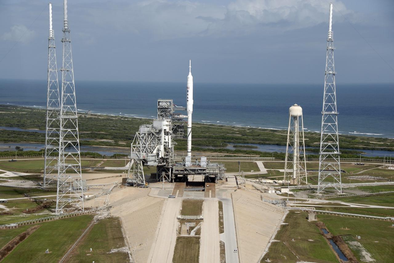
CAPE CANAVERAL, Fla. - Waves break along the Atlantic shoreline near Launch Pad 39B at NASA's Kennedy Space Center in Florida. On the pad, the Ares I-X rocket awaits liftoff on its upcoming flight test. This is the first time since the Apollo Program's Saturn rockets were retired that a vehicle other than the space shuttle has occupied the pad. Modifications to the pad to support the Ares I-X included the removal of shuttle unique subsystems, such as the orbiter access arm and a section of the gaseous oxygen vent arm, and the installation of three 600-foot lightning towers, access platforms, environmental control systems and a vehicle stabilization system. Part of the Constellation Program, the Ares I-X is the test vehicle for the Ares I. The Ares I-X flight test is set for Oct. 27. For information on the Ares I-X vehicle and flight test, visit http://www.nasa.gov/aresIX. Photo credit: NASA/Kim Shiflett
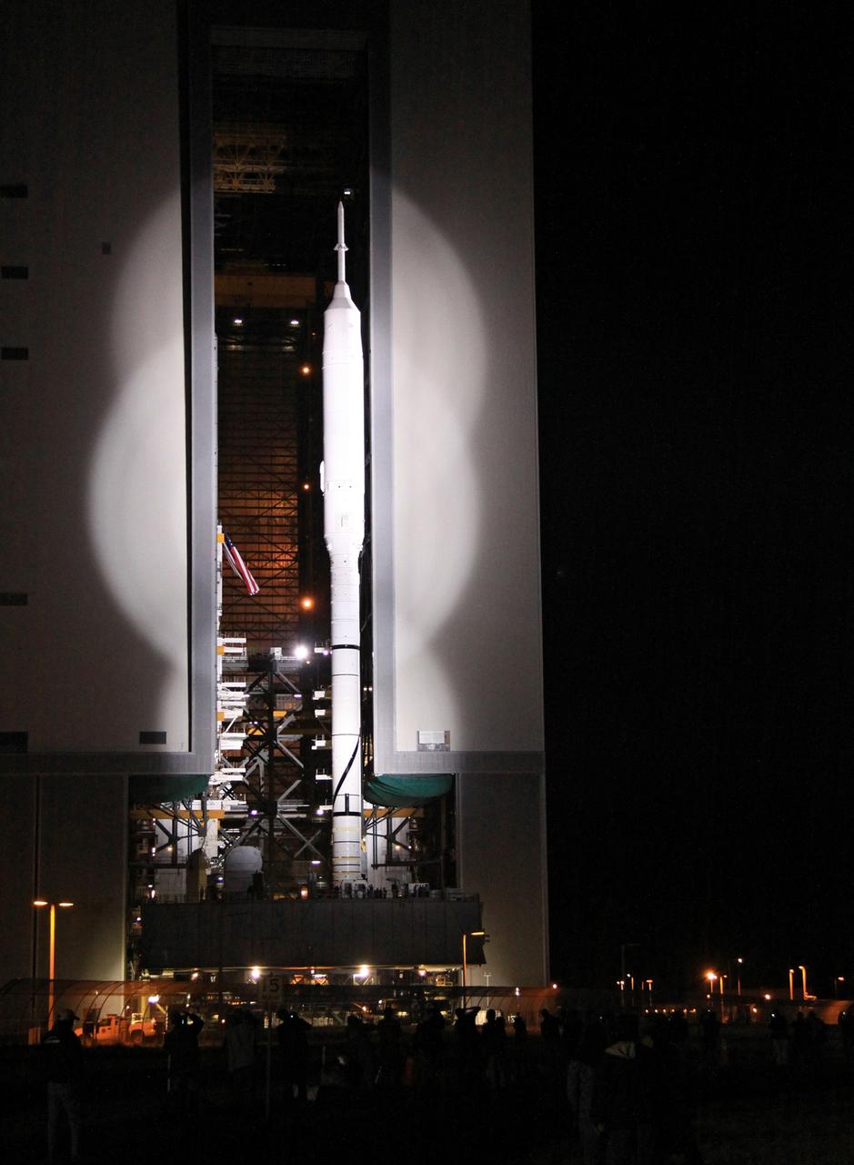
CAPE CANAVERAL, Fla. – Spotlighted in brilliant white, the 327-foot-tall Ares I-X rocket emerges from the Vehicle Assembly Building at NASA's Kennedy Space Center in Florida. The move to the launch pad, known as "rollout," began at 1:39 a.m. EDT. The transfer of the pad from the Space Shuttle Program to the Constellation Program took place May 31. Modifications made to the pad include the removal of shuttle unique subsystems, such as the orbiter access arm and a section of the gaseous oxygen vent arm, along with the installation of three 600-foot lightning towers, access platforms, environmental control systems and a vehicle stabilization system. Part of the Constellation Program, the Ares I-X is the test vehicle for the Ares I. The Ares I-X flight test is targeted for Oct. 27. For information on the Ares I-X vehicle and flight test, visit http://www.nasa.gov/aresIX. Photo credit: NASA/Jack Pfaller
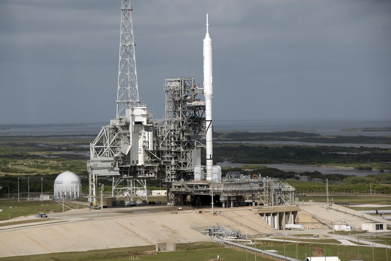
CAPE CANAVERAL, Fla. - At Launch Pad 39B at NASA's Kennedy Space Center in Florida, the Ares I-X rocket, secured to its mobile launcher platform, awaits liftoff on its upcoming flight test. This is the first time since the Apollo Program's Saturn rockets were retired that a vehicle other than the space shuttle has occupied the pad. Modifications to the pad to support the Ares I-X included the removal of shuttle unique subsystems, such as the orbiter access arm and a section of the gaseous oxygen vent arm, and the installation of three 600-foot lightning towers, access platforms, environmental control systems and a vehicle stabilization system. Part of the Constellation Program, the Ares I-X is the test vehicle for the Ares I. The Ares I-X flight test is set for Oct. 27. For information on the Ares I-X vehicle and flight test, visit http://www.nasa.gov/aresIX. Photo credit: NASA/Kim Shiflett
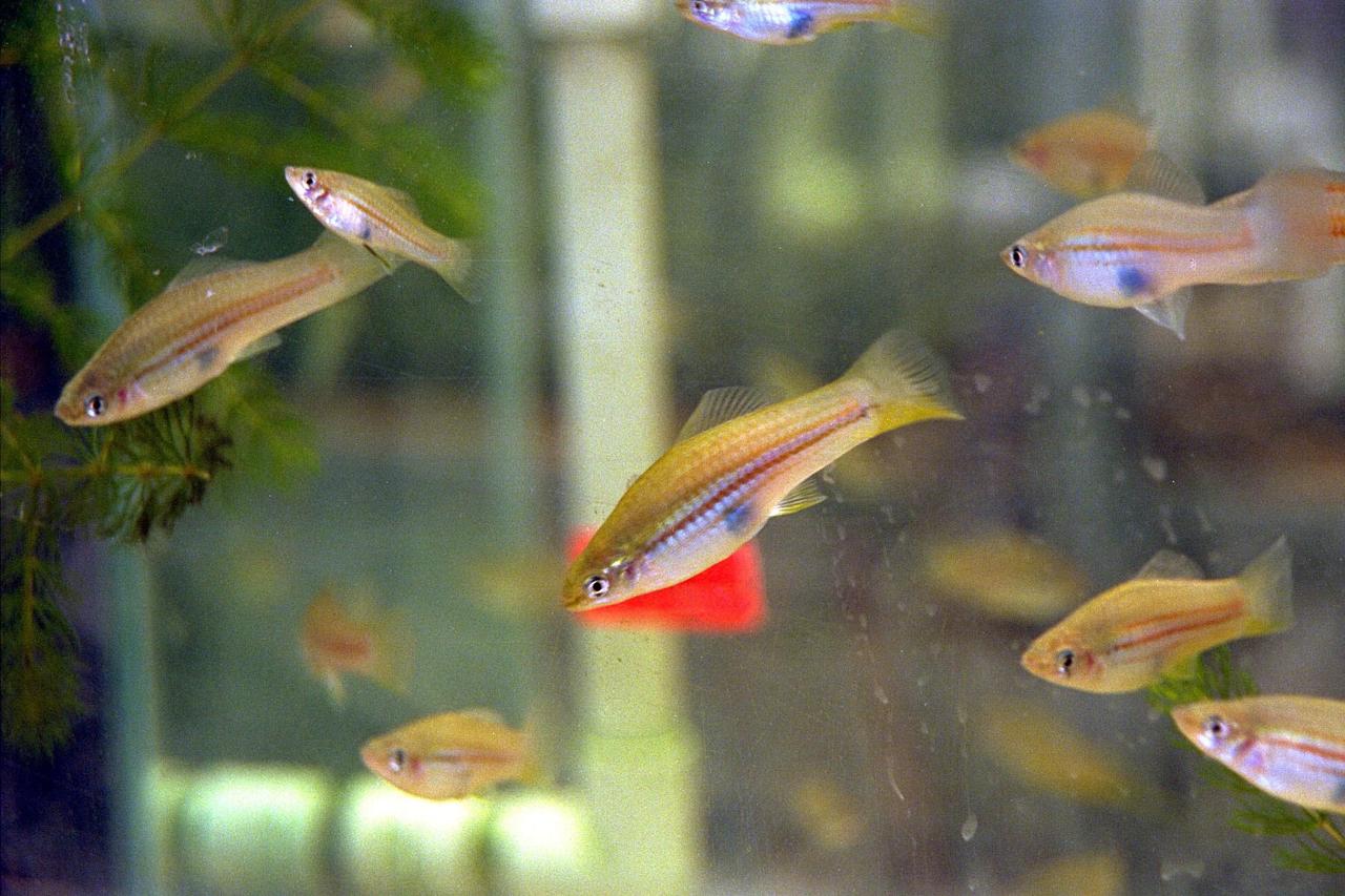
KENNEDY SPACE CENTER, FLA. -- Swordtail fish (Xiphophorus helleri), like those that are part of the Neurolab payload on Space Shuttle Mission STS-90, are shown in their holding tank in the Operations and Checkout Building. The fish will fly in the Closed Equilibrated Biological Aquatic System (CEBAS) Minimodule, a middeck locker-sized fresh water habitat, designed to allow the controlled incubation of aquatic species in a self-stabilizing, artifical ecosystem for up to three weeks under space conditions. Investigations during the Neurolab mission will focus on the effects of microgravity on the nervous system. The crew of STS-90, slated for launch April 16 at 2:19 p.m. EDT, include Commander Richard Searfoss, Pilot Scott Altman, Mission Specialists Richard Linnehan, D.V.M., Dafydd (Dave) Williams, M.D., and Kathryn (Kay) Hire, and Payload Specialists Jay Buckey, M.D., and James Pawelczyk, Ph.D.
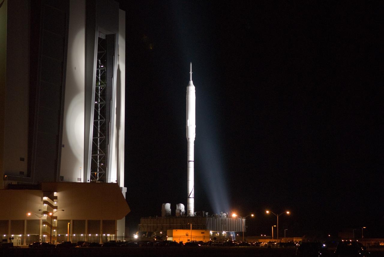
CAPE CANAVERAL, Fla. – The 327-foot-tall Ares I-X rocket clears the door of the Vehicle Assembly Building at NASA's Kennedy Space Center in Florida, on its way to Launch Pad 39B. The move to the launch pad, known as "rollout," began at 1:39 a.m. EDT. The transfer of the pad from the Space Shuttle Program to the Constellation Program took place May 31. Modifications made to the pad include the removal of shuttle unique subsystems, such as the orbiter access arm and a section of the gaseous oxygen vent arm, along with the installation of three 600-foot lightning towers, access platforms, environmental control systems and a vehicle stabilization system. Part of the Constellation Program, the Ares I-X is the test vehicle for the Ares I. The Ares I-X flight test is targeted for Oct. 27. For information on the Ares I-X vehicle and flight test, visit http://www.nasa.gov/aresIX. Photo credit: NASA/Jack Pfaller
CAPE CANAVERAL, Fla. – As the sun falls behind Launch Pad 39B at NASA's Kennedy Space Center in Florida, the rotating service structure, or RSS, has been retracted from the 327-foot-tall Ares I-X rocket to allow a full test of the rocket to be conducted. The transfer of the pad from the Space Shuttle Program to the Constellation Program took place May 31. Modifications made to the pad include the removal of shuttle unique subsystems, such as the orbiter access arm and a section of the gaseous oxygen vent arm, along with the installation of three 600-foot lightning towers, access platforms, environmental control systems and a vehicle stabilization system. Part of the Constellation Program, the Ares I-X is the test vehicle for the Ares I. The Ares I-X flight test is targeted for Oct. 27. For information on the Ares I-X vehicle and flight test, visit http://www.nasa.gov/aresIX. Photo credit: NASA/Jack Pfaller
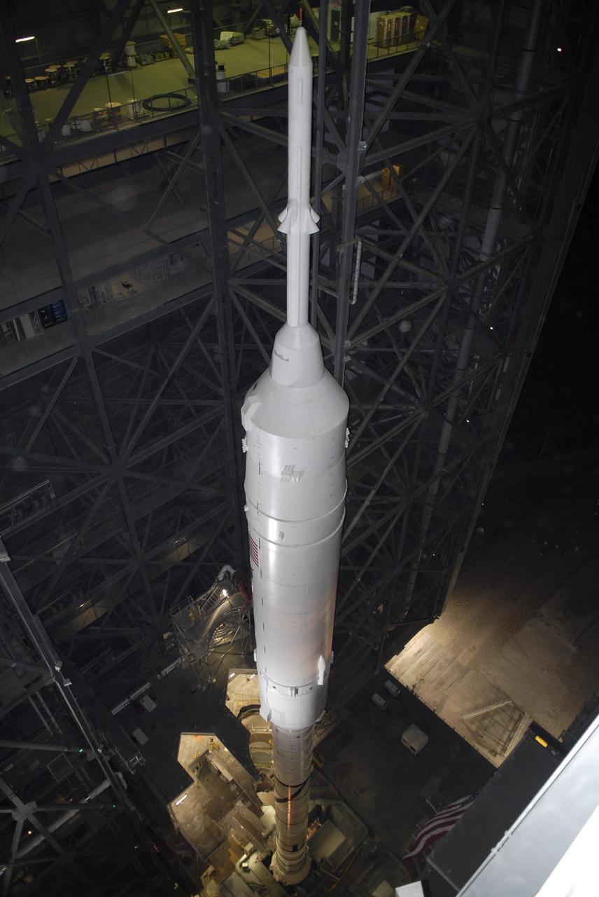
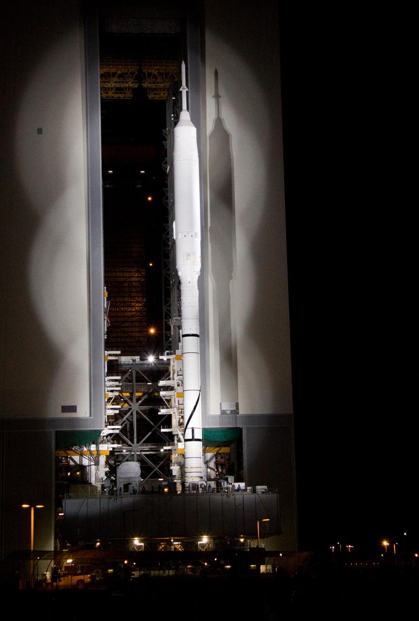
CAPE CANAVERAL, Fla. - Inside the Vehicle Assembly Building at NASA's Kennedy Space Center in Florida, the 327-foot-tall Ares I-X rocket stands on its mobile launcher platform. The transfer of the pad from the Space Shuttle Program to the Constellation Program took place May 31. Modifications made to the pad include the removal of shuttle unique subsystems, such as the orbiter access arm and a section of the gaseous oxygen vent arm, along with the installation of three 600-foot lightning towers, access platforms, environmental control systems and a vehicle stabilization system. Part of the Constellation Program, the Ares I-X is the test vehicle for the Ares I. The Ares I-X flight test is targeted for Oct. 27. For information on the Ares I-X vehicle and flight test, visit http://www.nasa.gov/aresIX. Photo credit: NASA/Kim Shiflett