
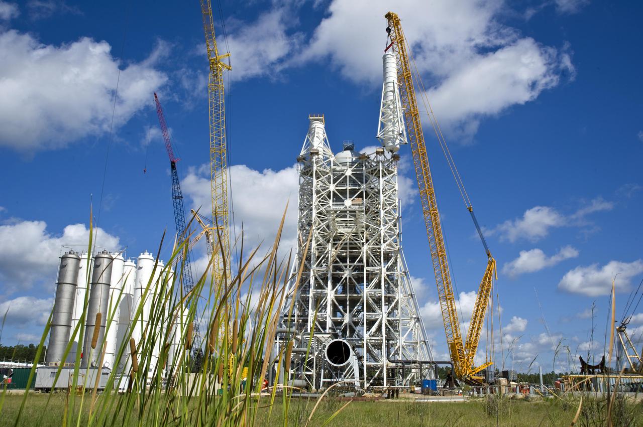
Stennis Space Center engineers celebrated a key milestone in construction of the A-3 Test Stand on April 9 - completion of structural steel work. Workers with Lafayette (La.) Steel Erector Inc. placed the last structural steel beam atop the stand during a noon ceremony attended by more than 100 workers and guests.
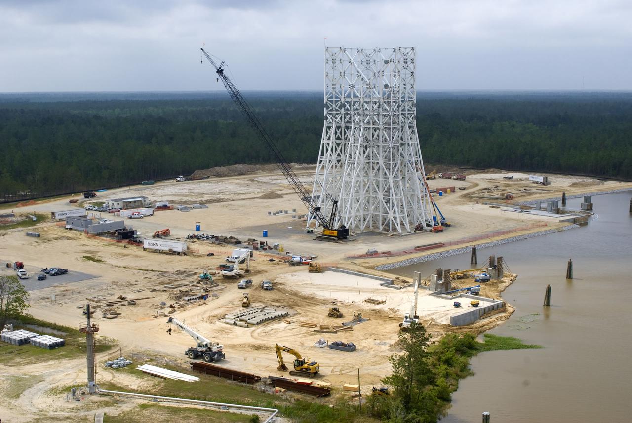
Structural steel work is completed on the 235-foot A-3 Test Stand at NASA's John C. Stennis Space Center. Stennis engineers celebrated this key milestone in construction April 9.
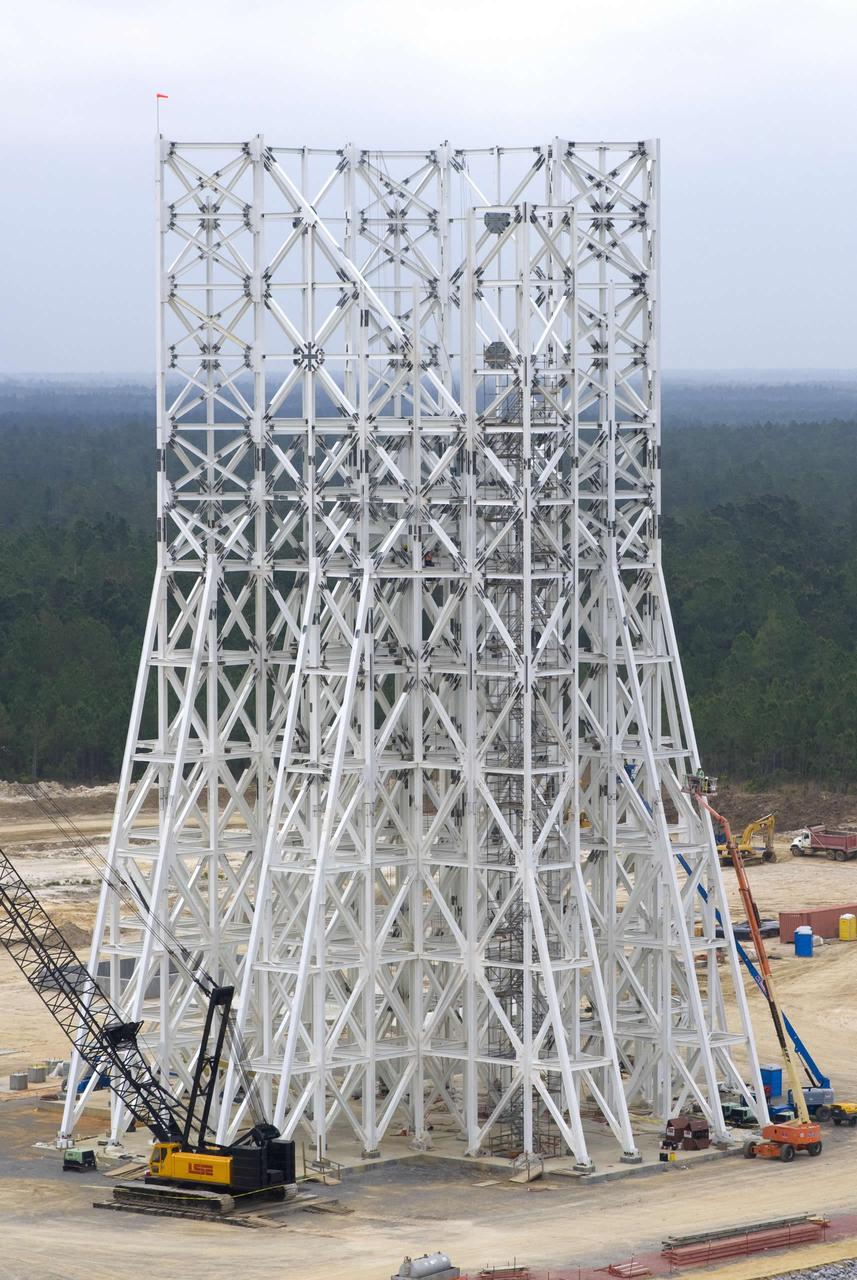
Structural steel work is completed on the 235-foot A-3 Test Stand at NASA's John C. Stennis Space Center. Stennis engineers celebrated this key milestone in construction April 9.
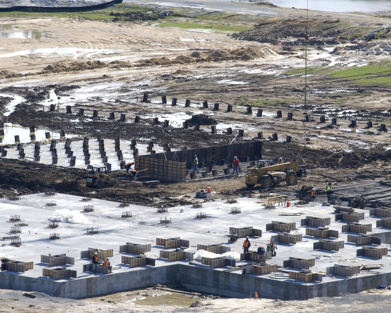
The concrete foundation placed Dec. 18 (foreground) for Stennis Space Center's future A-3 Test Stand has almost completely cured by early January, according to Bo Clarke, NASA's contracting officer technical representative for the foundation contract. By late December, construction on foundations for many of the test stand's support structures - diffuser, liquid oxygen, isopropyl alcohol and water tanks and gaseous nitrogen bottle battery - had begun with the installation of (background) `mud slabs.' The slabs provide a working surface for the reinforcing steel and foundation forms.
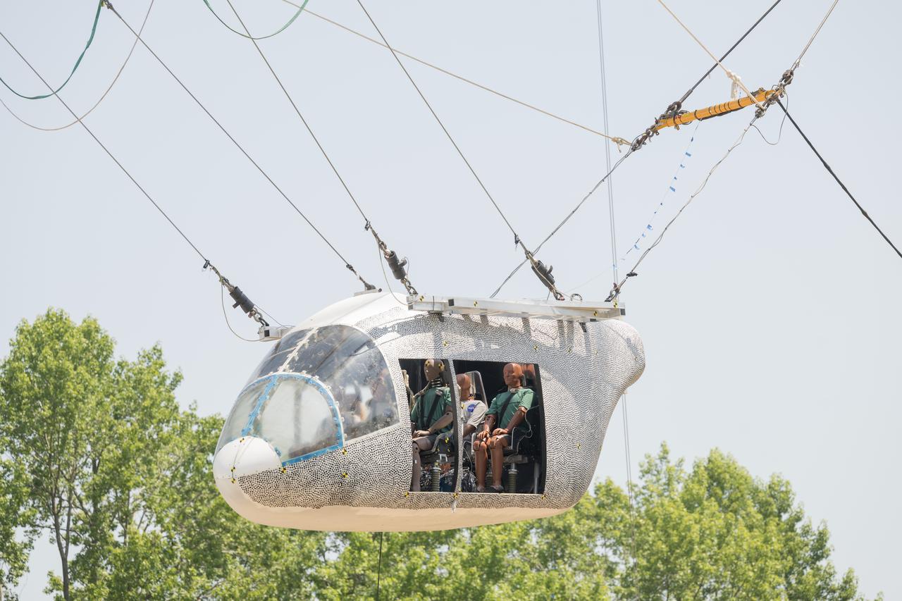
An aircraft body modeled after an air taxi with weighted test dummies inside is hoisted about 35 feet in the air by cables at NASA’s Langley Research Center in Hampton, Virginia. The aircraft was dropped from a tall steel structure, known as a gantry, on June 26 at Langley’s Landing and Impact Research Facility. NASA researchers are investigating aircraft materials that best absorb impact forces in a crash.
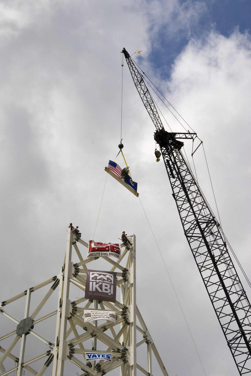
The final structural steel beam, bearing flags and the names of project workers, is hoisted and fastened into place atop the A-3 Test Stand.
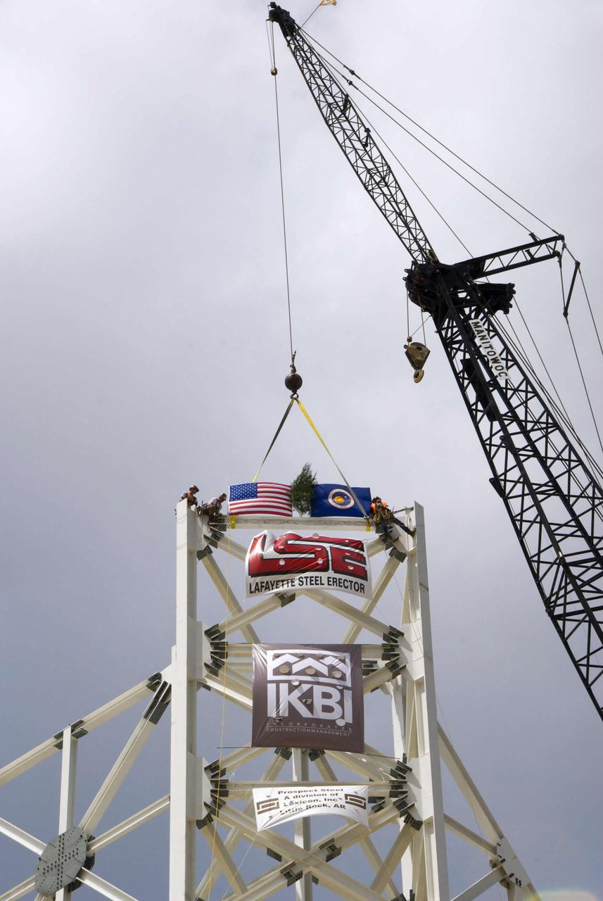
The final structural steel beam, bearing flags and the names of project workers, is hoisted and fastened into place atop the A-3 Test Stand.
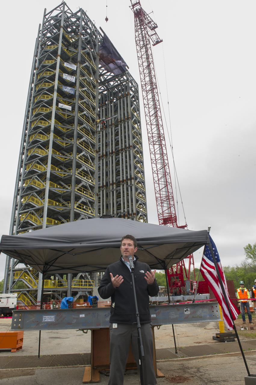
PHIL HENDRIX, SPEAKS TO THE CROWD IN FRONT OF A STEEL BEAM DESTINED FOR TEST STAND 4693 DURING THE STRUCTURE'S TOPPING OUT CEREMONY APRIL 12.
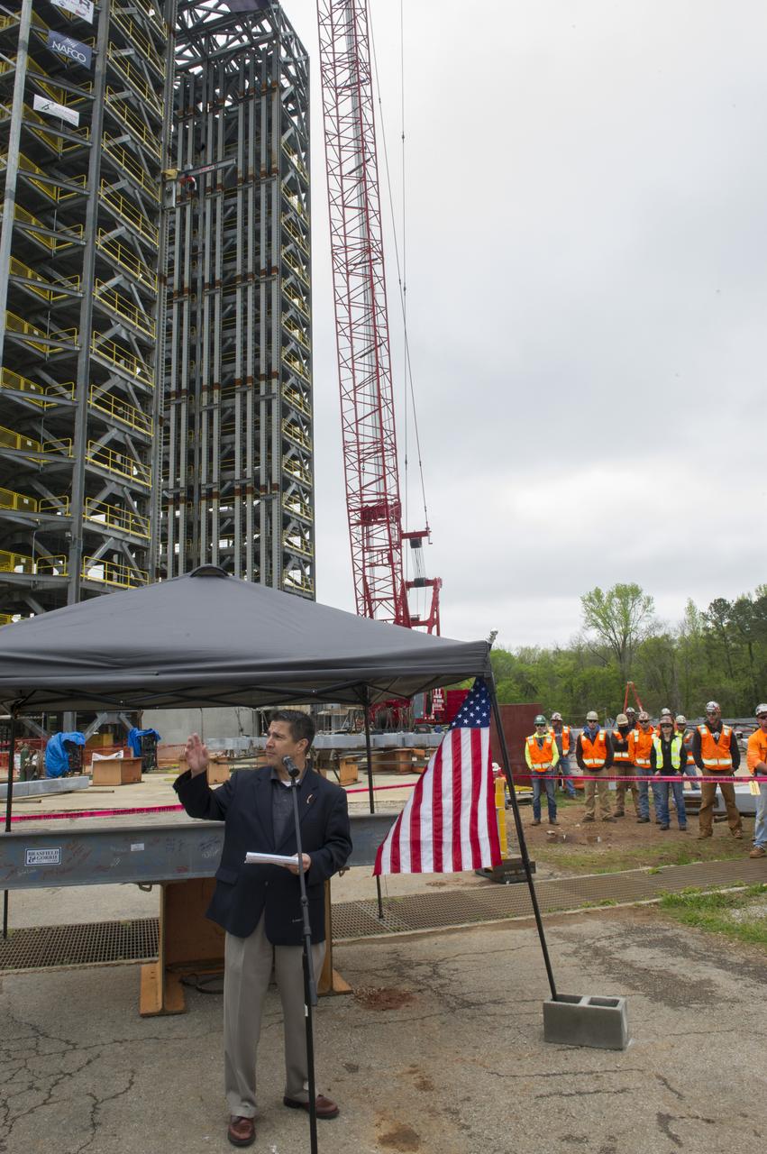
TIM FLORES SPEAKS TO THE CROWD IN FRONT OF A STEEL BEAM DESTINED FOR TEST STAND 4693 DURING THE STRUCTURE'S TOPPING OUT CEREMONY APRIL 12.
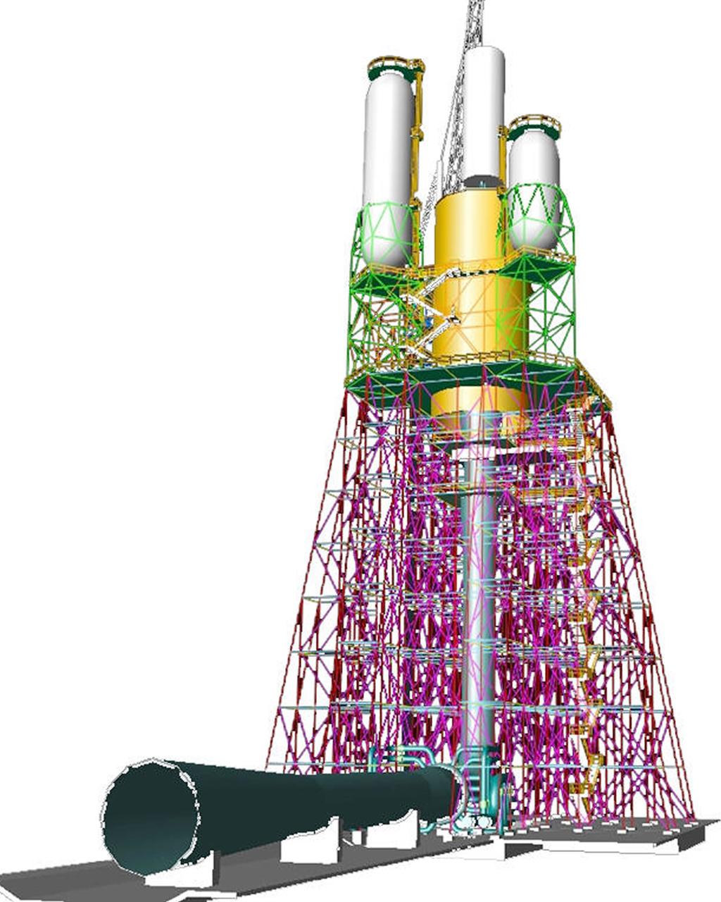
This engineer's concept drawing of the A-3 Test Stand shows the 300-foot-tall structure's open steel frame and large exhaust diffuser.
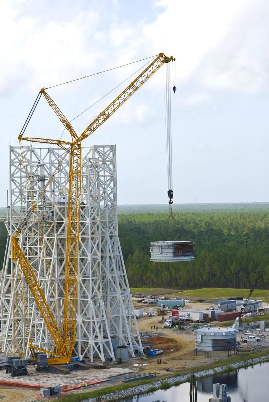
Employees at Stennis Space Center continue work on the A-3 Test Stand. As shown, a section of the test cell is lifted for installation on the stand's structural steel frame. Work on the A-3 Test Stand began in 2007. It is scheduled for activation in 2012.
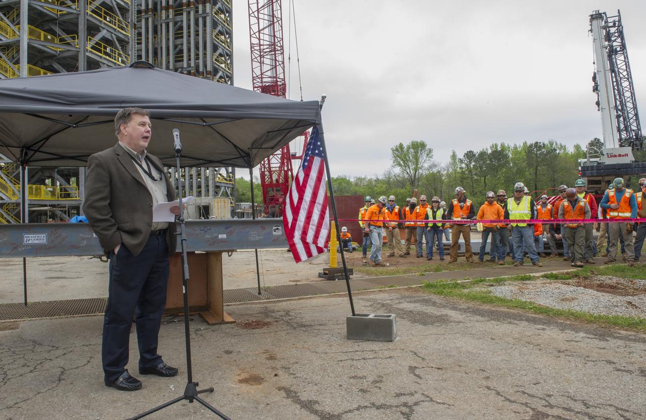
BOB DEVLIN, DEPUTY DIRECTOR OF MARSHALL'S OFFICE OF CENTER OPERATIONS, SPEAKS TO THE CROWD IN FRONT OF A STEEL BEAM DESTINED FOR TEST STAND 4693 DURING THE STRUCTURE'S TOPPING OUT CEREMONY APRIL 12.
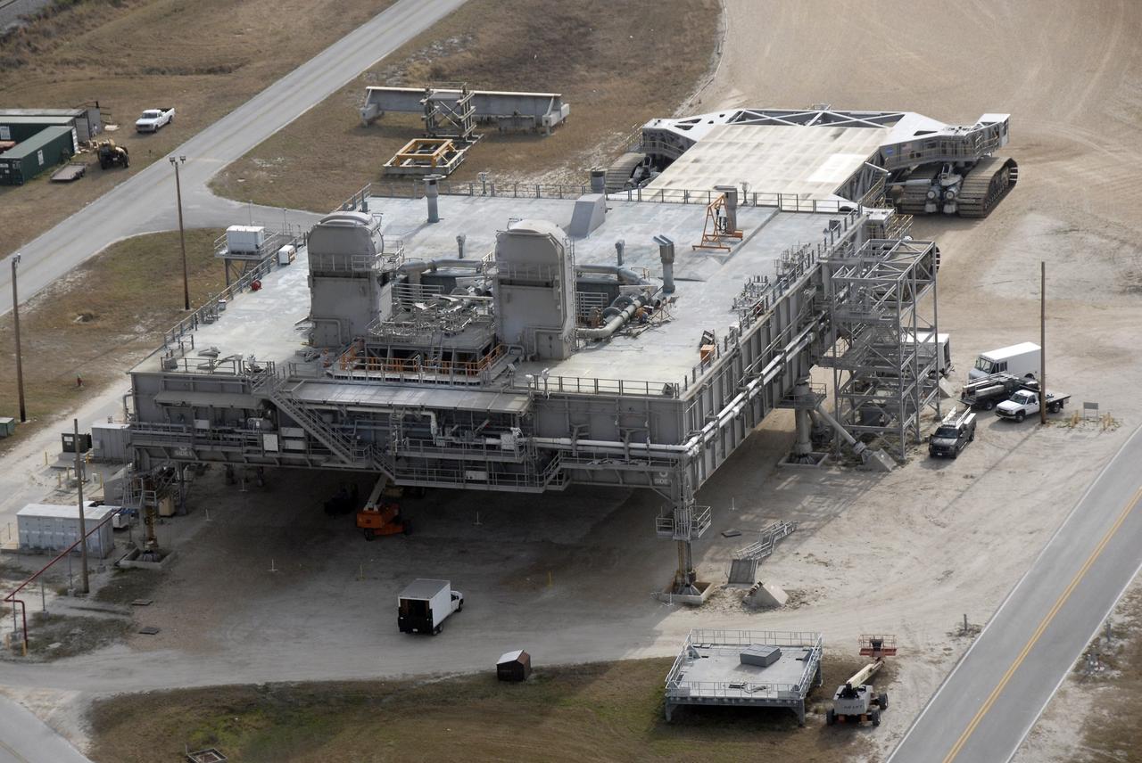
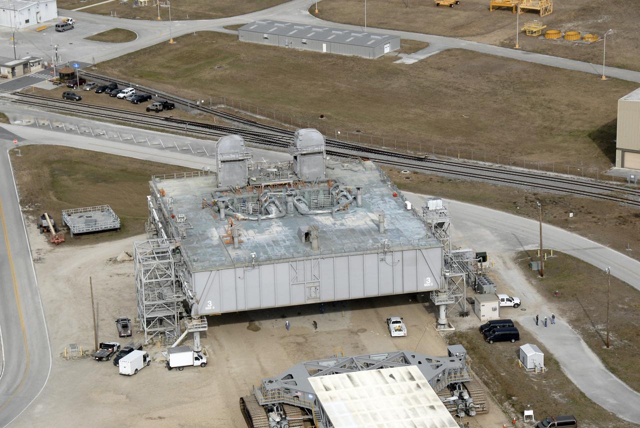
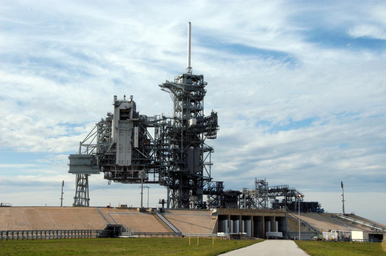
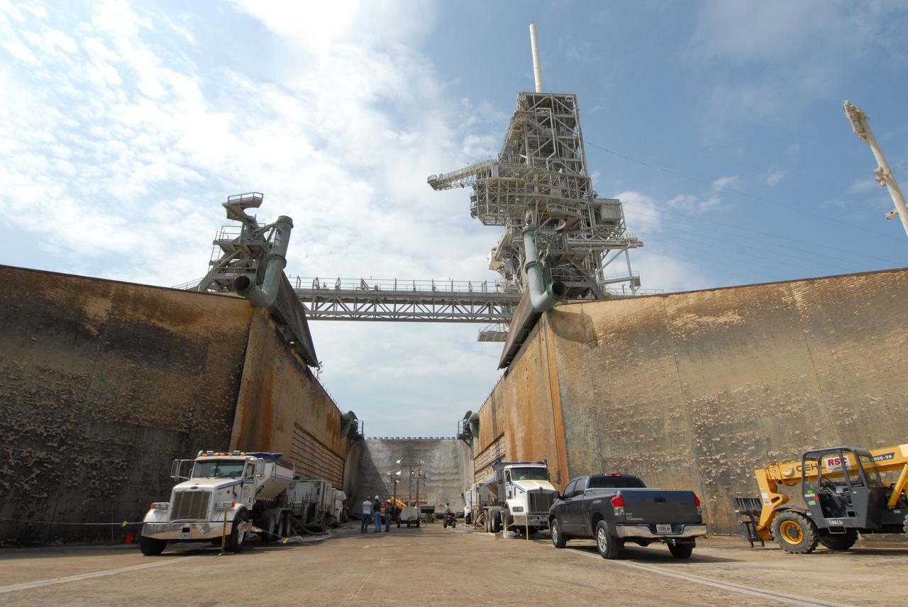
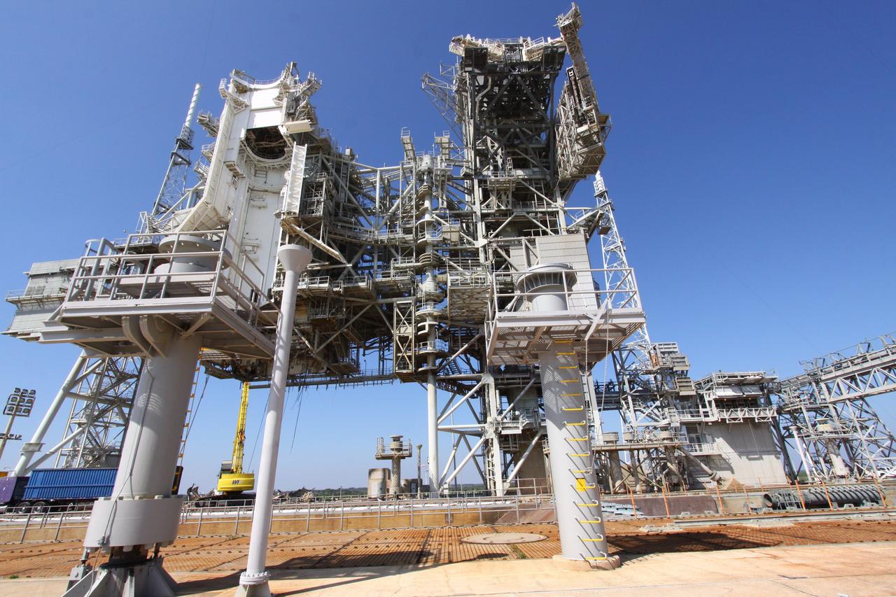
CAPE CANAVERAL, Fla. – An aerial view of a mobile launcher platform that is parked in the Launch Complex 39 Area at NASA's Kennedy Space Center in Florida. The platform, which is a moveable base for the launch of space shuttle, is a two-story steel structure 25 feet high, 160 feet long and 135 feet wide. It is constructed of welded steel up to 6 inches thick. The platform rests on six 22-foot-tall pedestals. Photo credit: NASA/Kim Shiflett
CAPE CANAVERAL, Fla. – An aerial view of a mobile launcher platform that is parked in the Launch Complex 39 Area at NASA's Kennedy Space Center in Florida. The platform, which is a moveable base for the launch of space shuttle, is a two-story steel structure 25 feet high, 160 feet long and 135 feet wide. It is constructed of welded steel up to 6 inches thick. The platform rests on six 22-foot-tall pedestals. Photo credit: NASA/Kim Shiflett

CAPE CANAVERAL, Fla. – An aerial view of a mobile launcher platform that is parked in the Launch Complex 39 Area at NASA's Kennedy Space Center in Florida. The platform, which is a moveable base for the launch of space shuttle, is a two-story steel structure 25 feet high, 160 feet long and 135 feet wide. It is constructed of welded steel up to 6 inches thick. The platform rests on six 22-foot-tall pedestals. Photo credit: NASA/Kim Shiflett

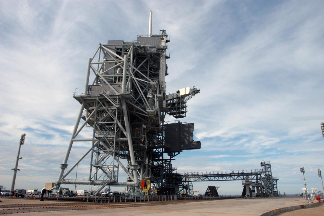
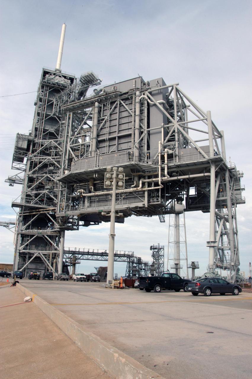
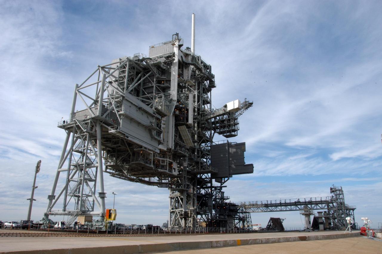
The rotating service structure on Launch Pad 39A is being moved for the first time in more than a year due to maintenance and upgrades on the pad. Some of the work included sandblasting the structure to remove rust and repainting. In addition, the RSS was jacked up and a new upper-bearing race assembly installed where the RSS pivots against the fixed service structure and a half-inch steel plate added. Pad 39A is being made ready for its first launch in four years, the upcoming STS-117 on March 15.

The rotating service structure on Launch Pad 39A has moved for the first time in more than a year due to maintenance and upgrades on the pad. Some of the work included sandblasting the structure to remove rust and repainting. In addition, the RSS was jacked up and a new upper-bearing race assembly installed where the RSS pivots against the fixed service structure and a half-inch steel plate added. Pad 39A is being made ready for its first launch in four years, the upcoming STS-117 on March 15.
The rotating service structure on Launch Pad 39A is being moved for the first time in more than a year due to maintenance and upgrades on the pad. Some of the work included sandblasting the structure to remove rust and repainting. In addition, the RSS was jacked up and a new upper-bearing race assembly installed where the RSS pivots against the fixed service structure and a half-inch steel plate added. Pad 39A is being made ready for its first launch in four years, the upcoming STS-117 on March 15.
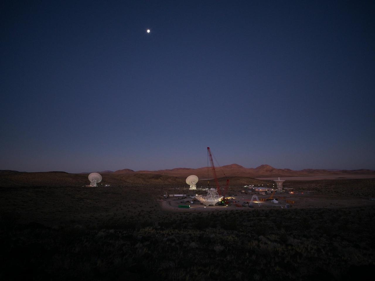
In the early morning of Dec. 18, 2024, a crane looms over the 112-foot-wide (34-meter-wide) steel framework for Deep Space Station 23 (DSS-23) reflector dish, which will soon be lowered into position on the antenna's base structure. Located at the Deep Space Network's Goldstone Space Communications Complex near Barstow, California, DSS-23 is a multi-frequency beam waveguide antenna that will boost the DSN's capacity and enhance NASA's deep space communications capabilities for decades to come. In the background are, from left to right, the beam waveguide antennas DSS-25 and DSS-26, and the decommissioned 85-foot (26-meter) Apollo antenna. https://photojournal.jpl.nasa.gov/catalog/PIA26456
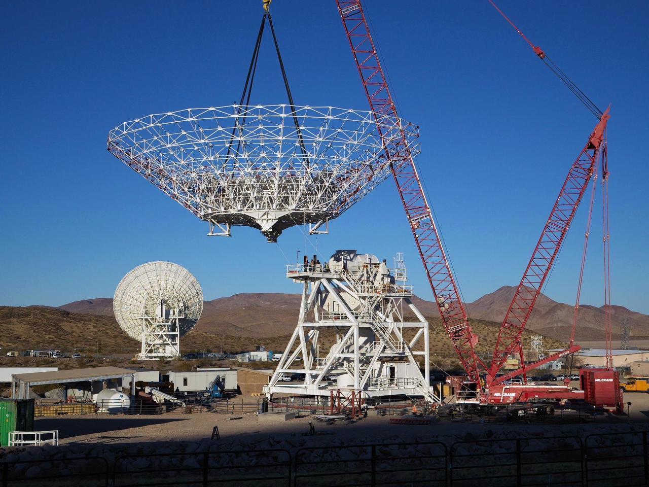
A crane lowers the 112-foot-wide (34-meter-wide) steel framework for the Deep Space Station 23 (DSS-23) reflector dish into position on Dec. 18, 2024, at the Deep Space Network's Goldstone Space Communications Complex near Barstow, California. A multi-frequency beam waveguide antenna, DSS-23 will boost the DSN's capacity and enhance NASA's deep space communications capabilities for decades to come. Once online in 2026, DSS-23 will be the fifth of six new beam waveguide antennas to be added to the network, following DSS-53, which was added at the DSN's Madrid complex in 2022. After the reflector skeleton was bolted into place, engineers placed what's called a quadripod into the center of the structure. A four-legged support structure weighing 16 ½ tons, the quadripod is fitted with a curved subreflector that will direct radio frequency signals from deep space that bounce off the main reflector into the antenna's pedestal where the antenna's receivers are housed. Next steps: to fit panels onto the steel skeleton of the parabolic reflector to create a curved surface to collect radio frequency signals. The DSN allows missions to track, send commands to, and receive scientific data from faraway spacecraft. It is managed by NASA's Jet Propulsion Laboratory in Southern California for the agency's Space Communications and Navigation (SCaN) program, which is located at NASA Headquarters within the Space Operations Mission Directorate. https://photojournal.jpl.nasa.gov/catalog/PIA26454
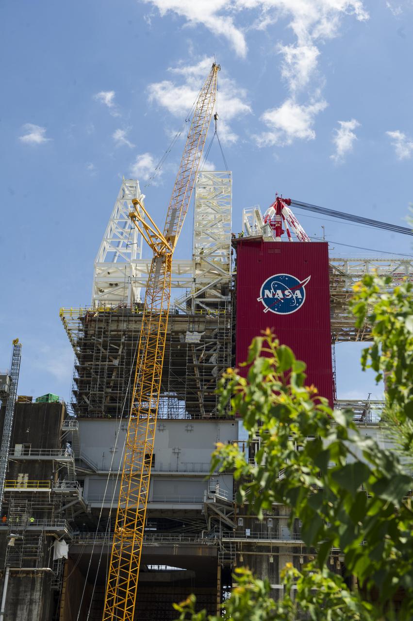
A structural steel section is lifted into place atop the B-2 Test Stand at NASA’s Stennis Space Center as part of modification work to prepare for testing the core stage of NASA’s new Space Launch System. The section is part of the Main Propulsion Test Article (MPTA) framework, which will support the SLS core stage for testing. The existing framework was installed on the stand in the late 1970s to test the shuttle MPTA. However, that framework had to be repositioned and modified to accommodate the larger SLS stage. About 1 million pounds of structural steel has been added, extending the framework about 100 feet higher and providing a new look to the Stennis skyline. Stennis will test the actual flight core stage for the first uncrewed SLS mission, Exploration Mission-1.
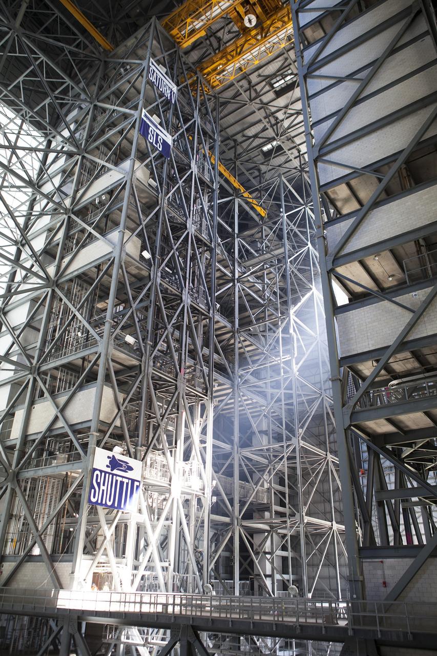
CAPE CANAVERAL, Fla. – Steel structures surround High Bay 3 inside the Vehicle Assembly Building, or VAB, at NASA’s Kennedy Space Center in Florida. In view, high above, is the 175-ton crane. Banners note the heights of the Saturn V, Space Launch System, or SLS, and shuttle on the steel structure. Modifications are underway in the VAB to prepare High Bay 3 for a new platform system. The modifications are part of a centerwide refurbishment initiative under the Ground Systems Development and Operations Program. High bay 3 is being refurbished to accommodate NASA’s Space Launch System and a variety of other spacecraft. For more information, visit http://www.nasa.gov/exploration/systems/ground/index.html. Photo credit: NASA/Dimitri Gerondidakis

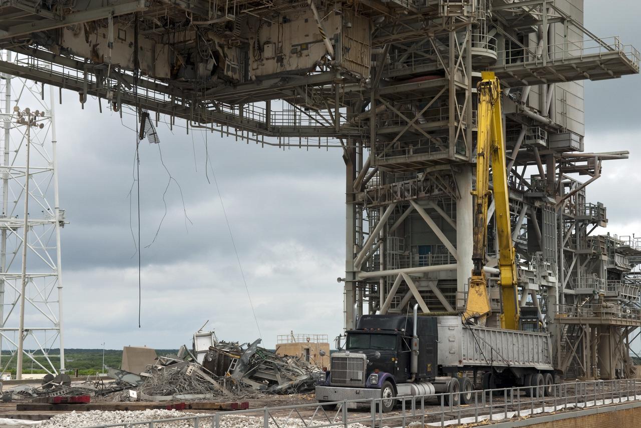
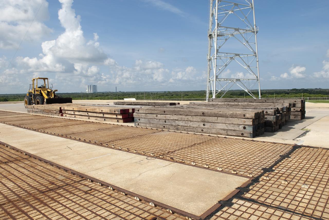
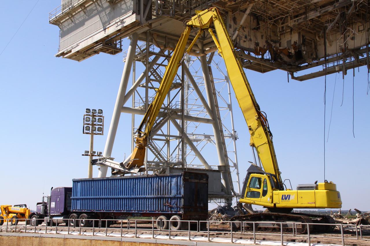
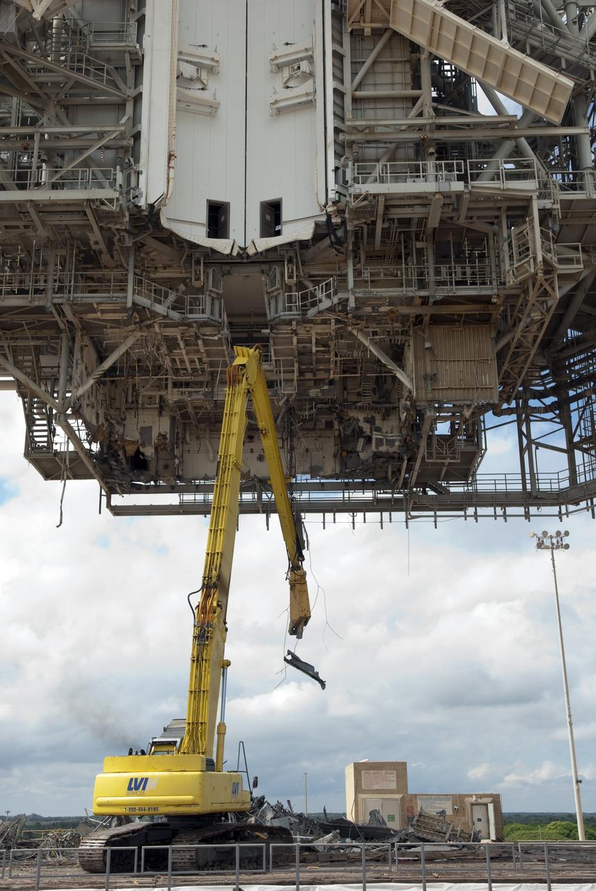
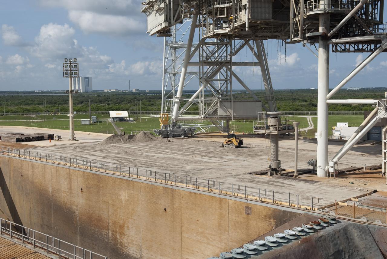
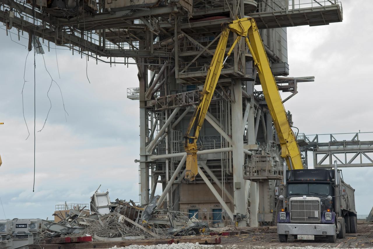
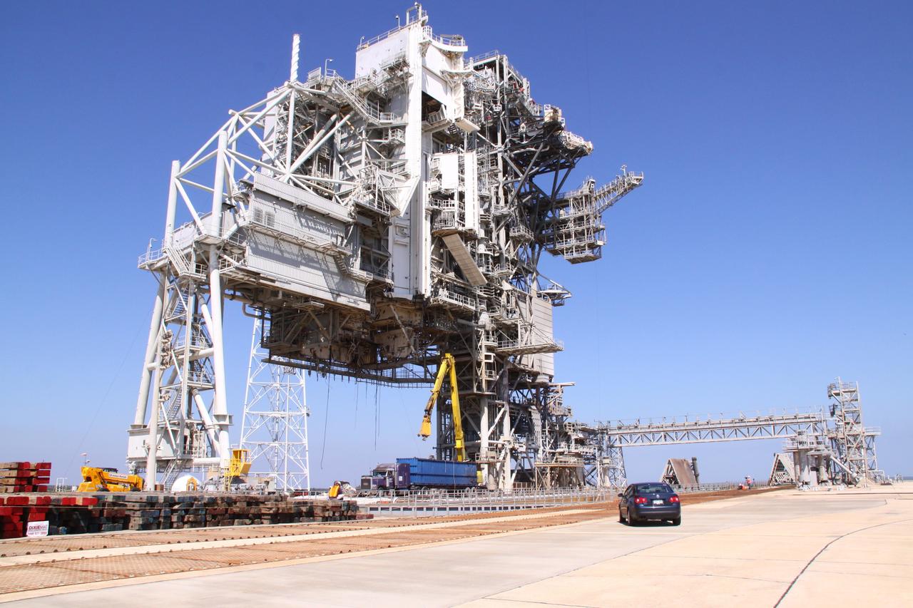
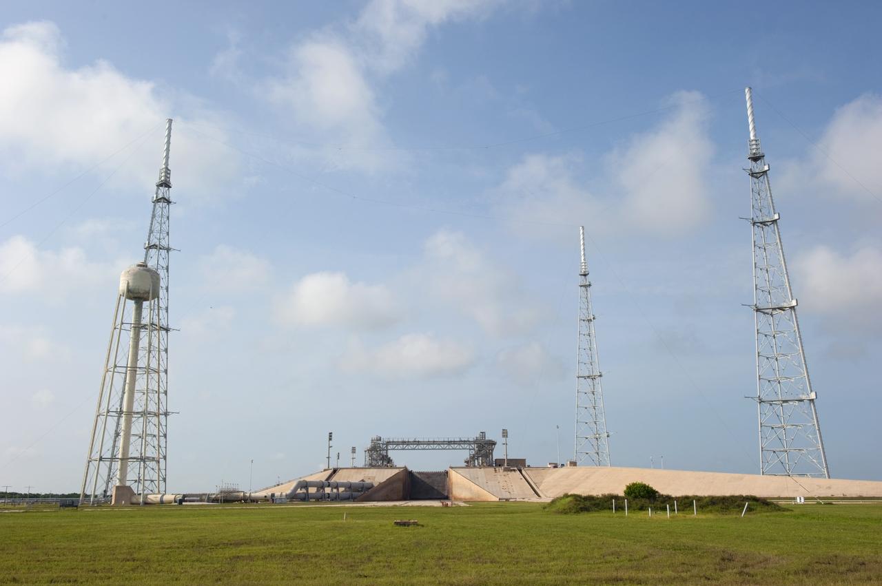
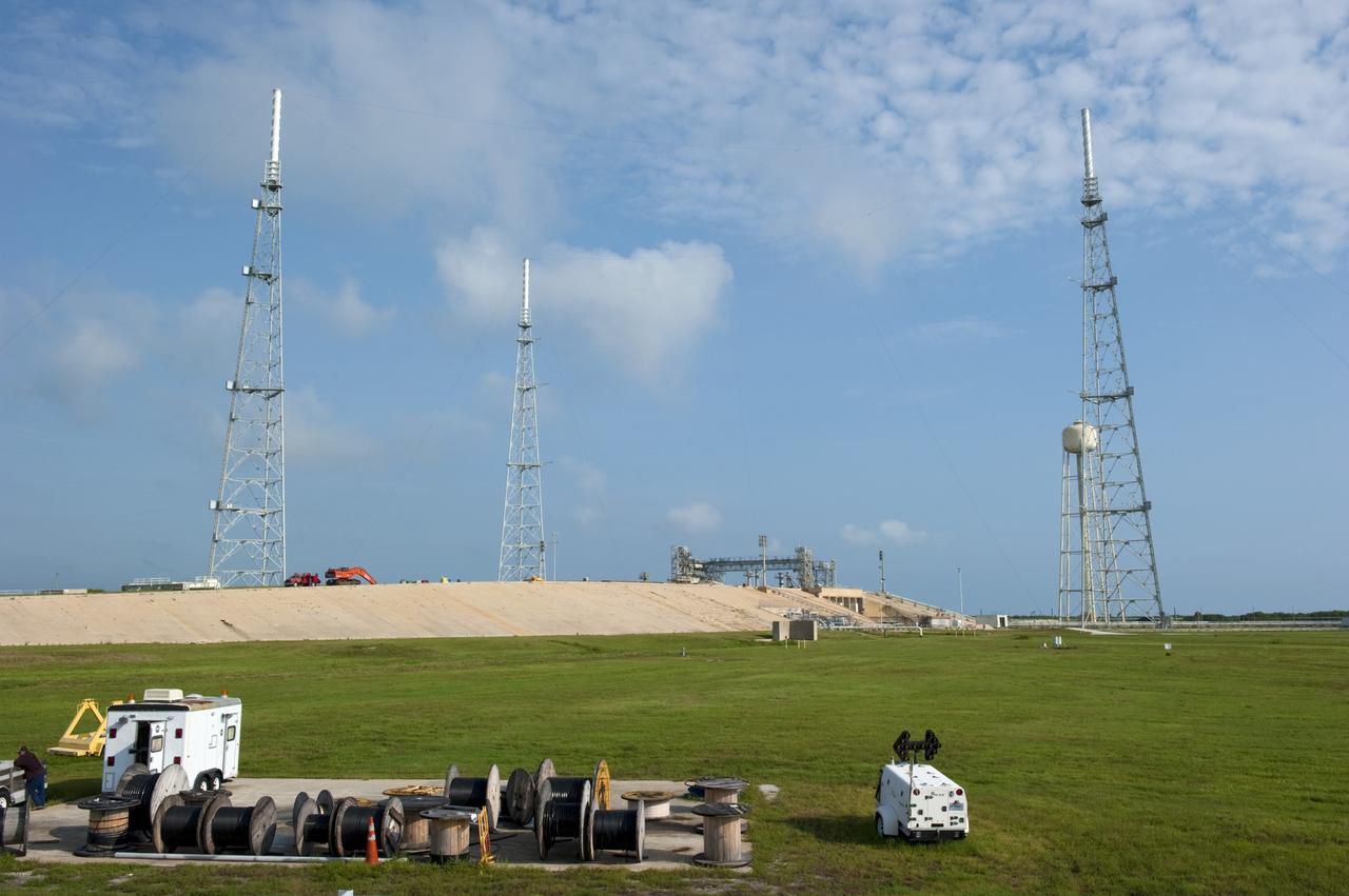
CAPE CANAVERAL, Fla. -- At NASA's Kennedy Space Center in Florida, the rotating service structure (RSS) on Launch Pad 39B is being dismantled. Sand, reinforcing steel and large wooden mats were put down under the RSS to protect the structure's concrete from falling debris during deconstruction. Starting in 2009, the structure at the pad was no longer needed for NASA's Space Shuttle Program, so it is being restructured for future use. The new design will feature a "clean pad" for rockets to come with their own launcher, making it more versatile for a number of vehicles. The new lightning protection system, consisting of three lightning towers and a wire catenary system will remain. Photo credit: NASA/Jim Grossmann
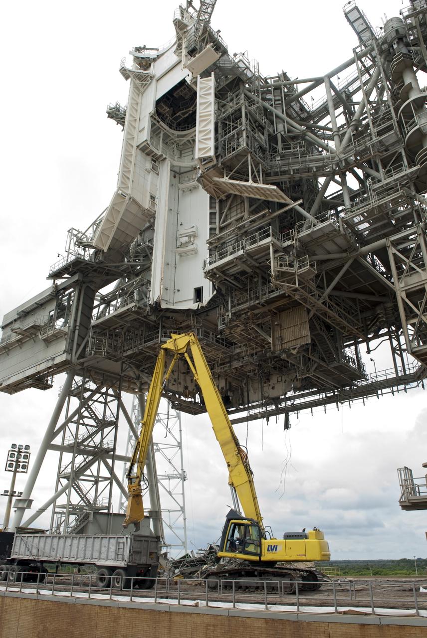
CAPE CANAVERAL, Fla. -- At NASA's Kennedy Space Center in Florida, crews are dismantling the rotating service structure (RSS) on Launch Pad 39B. Sand, reinforcing steel and large wooden mats were put down under the RSS to protect the structure's concrete from falling debris during deconstruction. Starting in 2009, the structure at the pad was no longer needed for NASA's Space Shuttle Program, so it is being restructured for future use. The new design will feature a "clean pad" for rockets to come with their own launcher, making it more versatile for a number of vehicles. The new lightning protection system, consisting of three lightning towers and a wire catenary system will remain. Photo credit: NASA/Jim Grossmann
CAPE CANAVERAL, Fla. -- At NASA's Kennedy Space Center in Florida, crews are dismantling the rotating service structure (RSS) on Launch Pad 39B. Sand, reinforcing steel and large wooden mats were put down under the RSS to protect the structure's concrete from falling debris during deconstruction. Starting in 2009, the structure at the pad was no longer needed for NASA's Space Shuttle Program, so it is being restructured for future use. The new design will feature a "clean pad" for rockets to come with their own launcher, making it more versatile for a number of vehicles. The new lightning protection system, consisting of three lightning towers and a wire catenary system will remain. Photo credit: NASA/Jim Grossmann
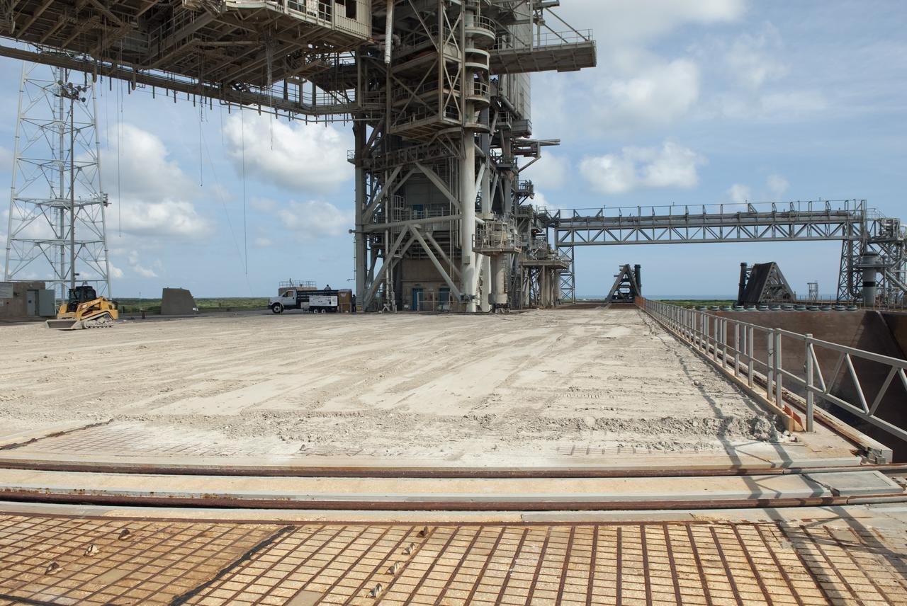
CAPE CANAVERAL, Fla. -- At NASA's Kennedy Space Center in Florida, construction crews lay sand, reinforcing steel and large wooden mats under the rotating service structure (RSS) of Launch Pad 39B to protect the structure's concrete from falling debris during deconstruction. Starting in 2009, the structure at the pad was no longer needed for NASA's Space Shuttle Program, so it is being restructured for future use. The new design will feature a "clean pad" for rockets to come with their own launcher, making it more versatile for a number of vehicles. For information on NASA's future plans, visit www.nasa.gov. Photo credit: NASA/Jim Grossmann
CAPE CANAVERAL, Fla. -- At NASA's Kennedy Space Center in Florida, the rotating service structure (RSS) on Launch Pad 39B is being dismantled. Sand, reinforcing steel and large wooden mats were put down under the RSS to protect the structure's concrete from falling debris during deconstruction. Starting in 2009, the structure at the pad was no longer needed for NASA's Space Shuttle Program, so it is being restructured for future use. The new design will feature a "clean pad" for rockets to come with their own launcher, making it more versatile for a number of vehicles. The new lightning protection system, consisting of three lightning towers and a wire catenary system will remain. Photo credit: NASA/Jim Grossmann
KENNEDY SPACE CENTER, FLA. -- The rotating service structure on Launch Pad 39A is being moved for the first time in more than a year due to maintenance and upgrades on the pad. Some of the work included sandblasting the structure to remove rust and repainting. In addition, the RSS was jacked up and a new upper-bearing race assembly installed where the RSS pivots against the fixed service structure and a half-inch steel plate added. Pad 39A is being made ready for its first launch in four years, the upcoming STS-117 on March 15. Photo credit: NASA/George Shelton
KENNEDY SPACE CENTER, FLA. -- The rotating service structure on Launch Pad 39A is being moved for the first time in more than a year due to maintenance and upgrades on the pad. Some of the work included sandblasting the structure to remove rust and repainting. In addition, the RSS was jacked up and a new upper-bearing race assembly installed where the RSS pivots against the fixed service structure and a half-inch steel plate added. Pad 39A is being made ready for its first launch in four years, the upcoming STS-117 on March 15. Photo credit: NASA/George Shelton

KENNEDY SPACE CENTER, FLA. -- Workers on Launch Pad 39A get ready to begin the movement of the rotating service structure above them. The RSS has not been rotated for more than a year during the maintenance and upgrades on the pad. Some of the work included sandblasting the structure to remove rust and repainting. In addition, the RSS was jacked up and a new upper-bearing race assembly installed where the RSS pivots against the fixed service structure and a half-inch steel plate added. Pad 39A is being made ready for its first launch in four years, the upcoming STS-117 on March 15. Photo credit: NASA/George Shelton

Workers on Launch Pad 39A get ready to begin the movement of the rotating service structure above them. The RSS has not been rotated for more than a year during the maintenance and upgrades on the pad. Some of the work included sandblasting the structure to remove rust and repainting. In addition, the RSS was jacked up and a new upper-bearing race assembly installed where the RSS pivots against the fixed service structure and a half-inch steel plate added. Pad 39A is being made ready for its first launch in four years, the upcoming STS-117 on March 15.
CAPE CANAVERAL, Fla. -- At NASA's Kennedy Space Center in Florida, construction crews lay sand, reinforcing steel and large wooden mats under the rotating service structure (RSS) of Launch Pad 39B to protect the structure's concrete from falling debris during deconstruction. Starting in 2009, the structure at the pad was no longer needed for NASA's Space Shuttle Program, so it is being restructured for future use. The new design will feature a "clean pad" for rockets to come with their own launcher, making it more versatile for a number of vehicles. For information on NASA's future plans, visit www.nasa.gov. Photo credit: NASA/Jim Grossmann
CAPE CANAVERAL, Fla. -- At NASA's Kennedy Space Center in Florida, crews continue dismantling the rotating service structure (RSS) on Launch Pad 39B. Sand, reinforcing steel and large wooden mats were put down under the RSS to protect the structure's concrete from falling debris during deconstruction. Starting in 2009, the structure at the pad was no longer needed for NASA's Space Shuttle Program, so it is being restructured for future use. The new design will feature a "clean pad" for rockets to come with their own launcher, making it more versatile for a number of vehicles. The new lightning protection system, consisting of three lightning towers and a wire catenary system will remain. Photo credit: NASA/Jack Pfaller
KENNEDY SPACE CENTER, FLA. -- The rotating service structure on Launch Pad 39A has moved for the first time in more than a year due to maintenance and upgrades on the pad. Some of the work included sandblasting the structure to remove rust and repainting. In addition, the RSS was jacked up and a new upper-bearing race assembly installed where the RSS pivots against the fixed service structure and a half-inch steel plate added. Pad 39A is being made ready for its first launch in four years, the upcoming STS-117 on March 15. Photo credit: NASA/George Shelton
CAPE CANAVERAL, Fla. -- At NASA's Kennedy Space Center in Florida, crews are dismantling the rotating service structure (RSS) on Launch Pad 39B. Sand, reinforcing steel and large wooden mats were put down under the RSS to protect the structure's concrete from falling debris during deconstruction. Starting in 2009, the structure at the pad was no longer needed for NASA's Space Shuttle Program, so it is being restructured for future use. The new design will feature a "clean pad" for rockets to come with their own launcher, making it more versatile for a number of vehicles. The new lightning protection system, consisting of three lightning towers and a wire catenary system will remain. Photo credit: NASA/Jim Grossmann
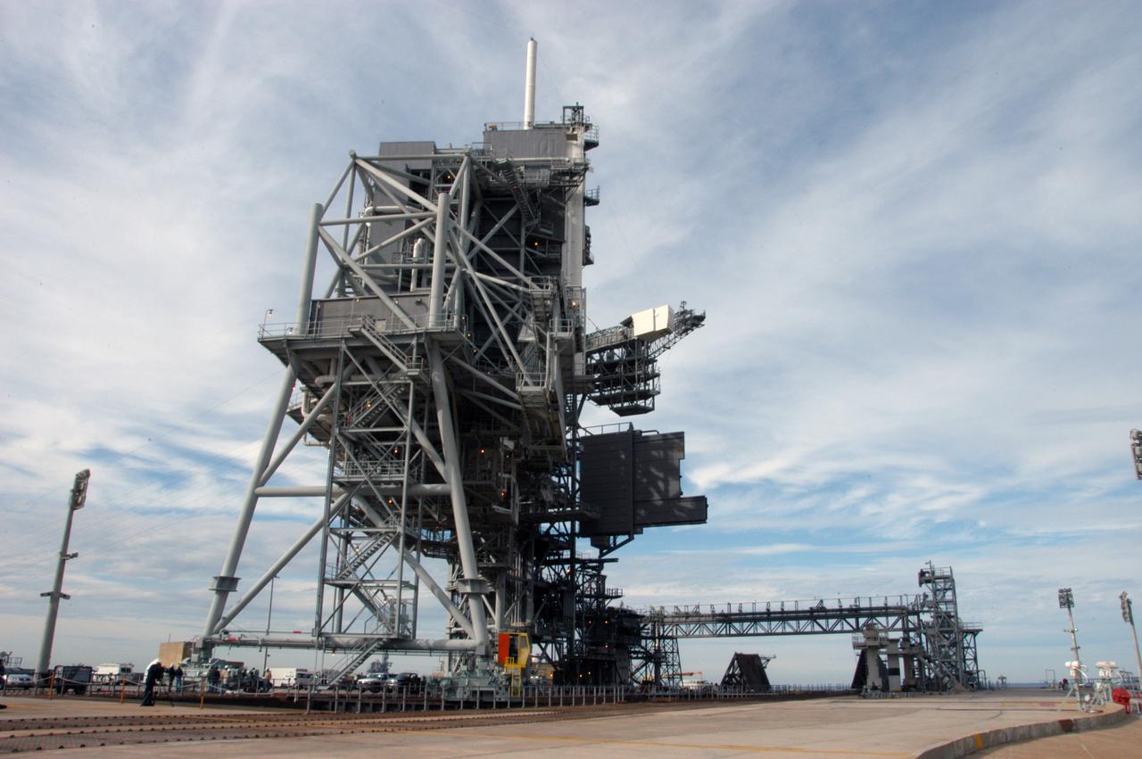
The rotating service structure on Launch Pad 39A has been fully opened for the first time in more than a year due to maintenance and upgrades on the pad. Some of the work included sandblasting the structure to remove rust and repainting. In addition, the RSS was jacked up and a new upper-bearing race assembly installed where the RSS pivots against the fixed service structure and a half-inch steel plate added. Pad 39A is being made ready for its first launch in four years, the upcoming STS-117 on March 15. Photo credit: NASA/George Shelton

KENNEDY SPACE CENTER, FLA. -- The rotating service structure on Launch Pad 39A has been fully opened for the first time in more than a year due to maintenance and upgrades on the pad. Some of the work included sandblasting the structure to remove rust and repainting. In addition, the RSS was jacked up and a new upper-bearing race assembly installed where the RSS pivots against the fixed service structure and a half-inch steel plate added. Pad 39A is being made ready for its first launch in four years, the upcoming STS-117 on March 15. Photo credit: NASA/George Shelton
CAPE CANAVERAL, Fla. -- At NASA's Kennedy Space Center in Florida, construction crews lay sand, reinforcing steel and large wooden mats under the rotating service structure (RSS) of Launch Pad 39B to protect the structure's concrete from falling debris during deconstruction. Starting in 2009, the structure at the pad was no longer needed for NASA's Space Shuttle Program, so it is being restructured for future use. The new design will feature a "clean pad" for rockets to come with their own launcher, making it more versatile for a number of vehicles. For information on NASA's future plans, visit www.nasa.gov. Photo credit: NASA/Jim Grossmann
CAPE CANAVERAL, Fla. -- At NASA's Kennedy Space Center in Florida, the rotating service structure (RSS) on Launch Pad 39B is being dismantled. Sand, reinforcing steel and large wooden mats were put down under the RSS to protect the structure's concrete from falling debris during deconstruction. Starting in 2009, the structure at the pad was no longer needed for NASA's Space Shuttle Program, so it is being restructured for future use. The new design will feature a "clean pad" for rockets to come with their own launcher, making it more versatile for a number of vehicles. The new lightning protection system, consisting of three lightning towers and a wire catenary system will remain. Photo credit: NASA/Jim Grossmann
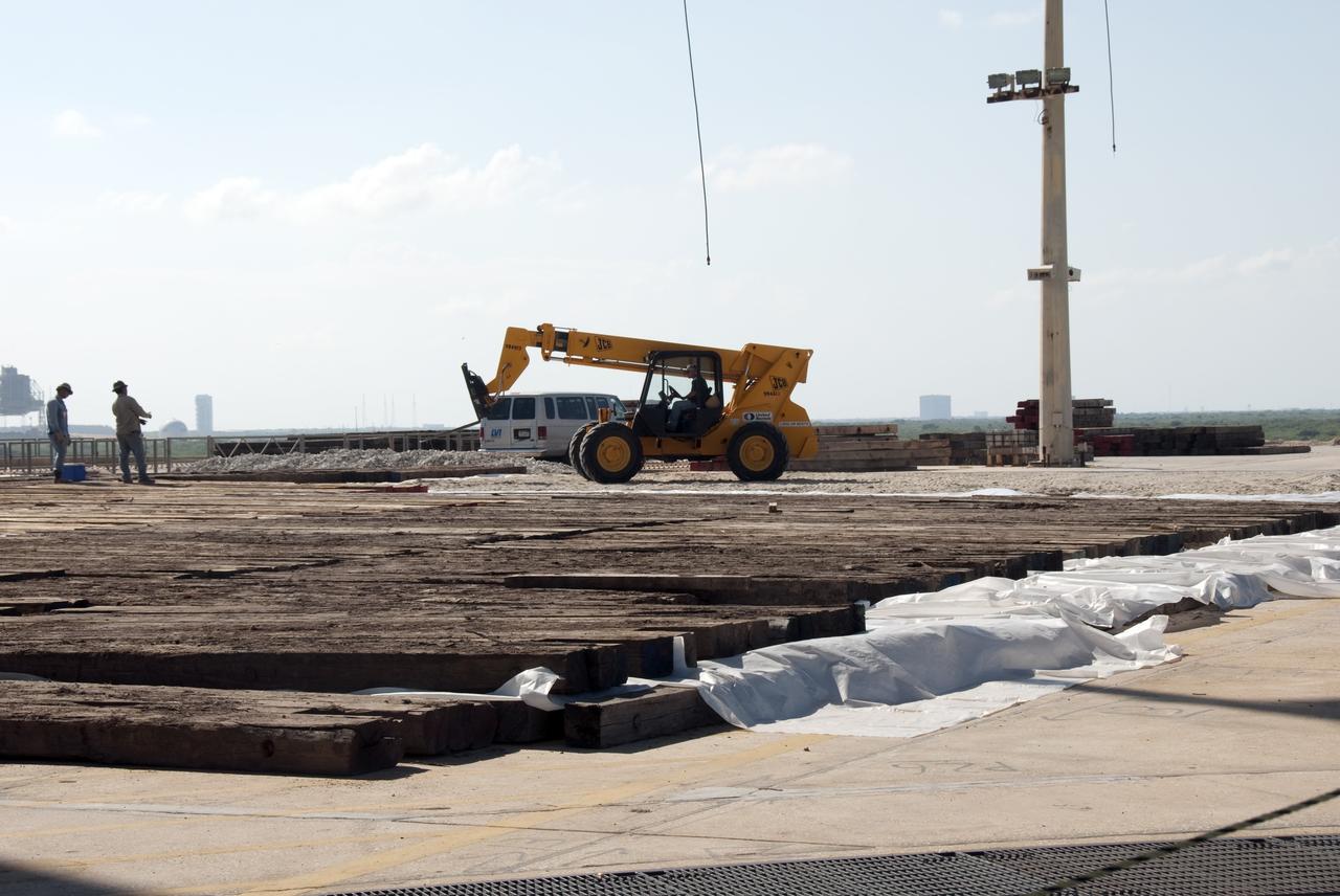
CAPE CANAVERAL, Fla. -- At NASA's Kennedy Space Center in Florida, construction crews lay large wooden mats on top of sand and reinforcing steel to protect the concrete under the rotating service structure (RSS) of Launch Pad 39B during deconstruction. Starting in 2009, the structure at Pad B was no longer needed for NASA's Space Shuttle Program, so it is being restructured for future use. The new design will feature a "clean pad" for rockets to come with their own launcher, making it more versatile for a number of vehicles. For information on NASA's future plans, visit www.nasa.gov. Photo credit: NASA/Jim Grossmann
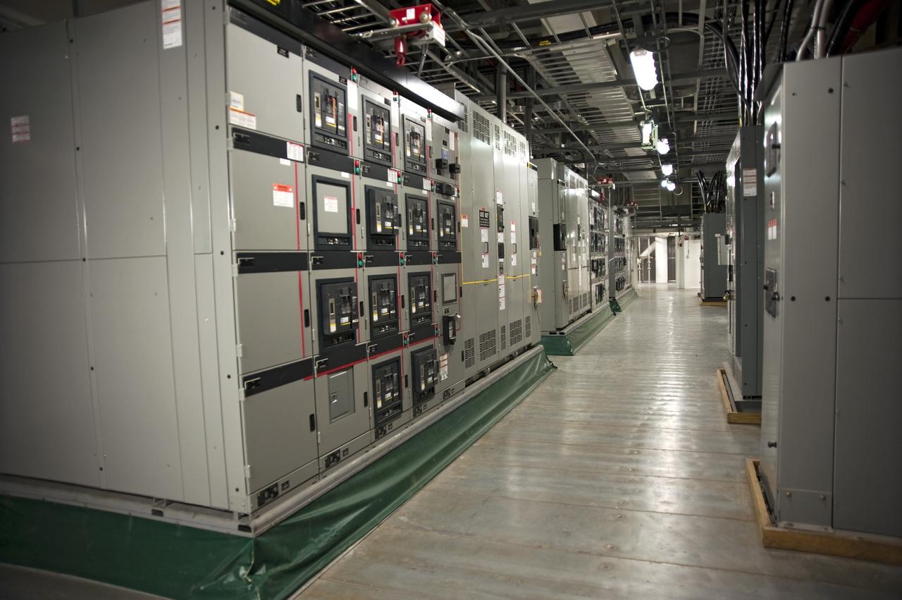
CAPE CANAVERAL, Fla. -- The interior of NASA's new mobile launcher, or ML, support structure is outfitted with solid steel flooring, lights, air conditioning, electrical boxes and sprinkler piping at NASA's Kennedy Space Center in Florida. The 355-foot-tall structure will support NASA's future human spaceflight program. The base of the launcher is lighter than space shuttle mobile launcher platforms so the crawler-transporter can pick up the heavier load of the tower and a taller rocket. The next step will be to add ground support equipment, such as umbilicals and access arms, for future rocket launches. For information on NASA's future plans, visit www.nasa.gov. Photo credit: NASA/Kim Shiflett
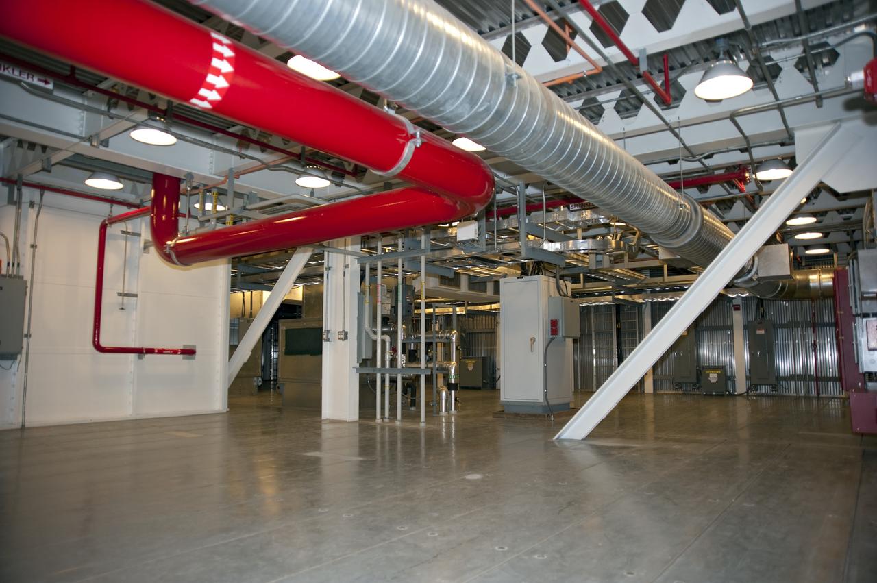
CAPE CANAVERAL, Fla. -- The interior of NASA's new mobile launcher, or ML, support structure is outfitted with solid steel flooring, lights, air conditioning, electrical boxes and sprinkler piping at NASA's Kennedy Space Center in Florida. The 355-foot-tall structure will support NASA's future human spaceflight program. The base of the launcher is lighter than space shuttle mobile launcher platforms so the crawler-transporter can pick up the heavier load of the tower and a taller rocket. The next step will be to add ground support equipment, such as umbilicals and access arms, for future rocket launches. For information on NASA's future plans, visit www.nasa.gov. Photo credit: NASA/Kim Shiflett
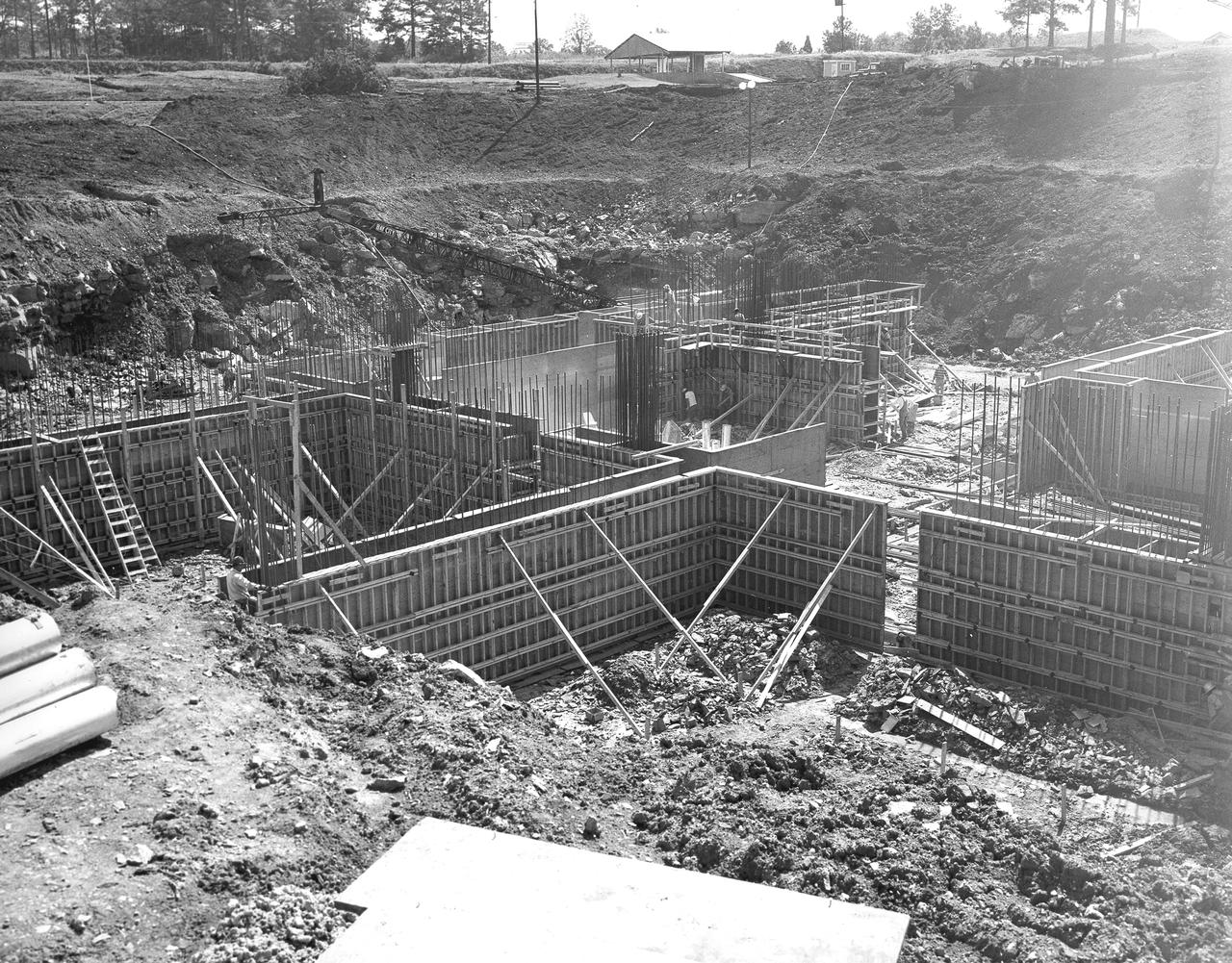
At its founding, the Marshall Space Flight Center (MSFC) inherited the Army’s Jupiter and Redstone test stands, but much larger facilities were needed for the giant stages of the Saturn V. From 1960 to 1964, the existing stands were remodeled and a sizable new test area was developed. The new comprehensive test complex for propulsion and structural dynamics was unique within the nation and the free world, and they remain so today because they were constructed with foresight to meet the future as well as on going needs. Construction of the S-IC Static test stand complex began in 1961 in the west test area of MSFC, and was completed in 1964. The S-IC static test stand was designed to develop and test the 138-ft long and 33-ft diameter Saturn V S-IC first stage, or booster stage, weighing in at 280,000 pounds. Required to hold down the brute force of a 7,500,000-pound thrust produced by 5 F-1 engines, the S-IC static test stand was designed and constructed with the strength of hundreds of tons of steel and 12,000,000 pounds of cement, planted down to bedrock 40 feet below ground level. The foundation walls, constructed with concrete and steel, are 4 feet thick. The base structure consists of four towers with 40-foot-thick walls extending upward 144 feet above ground level. The structure was topped by a crane with a 135-foot boom. With the boom in the upright position, the stand was given an overall height of 405 feet, placing it among the highest structures in Alabama at the time. This photo, taken September 15, 1961, shows the installation of the reinforcing steel prior to the pouring of the concrete foundation walls.
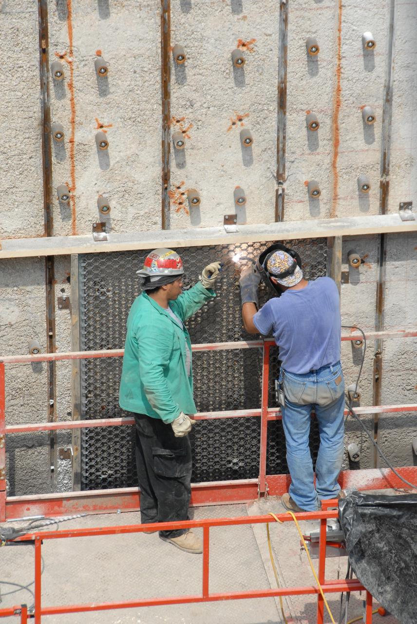
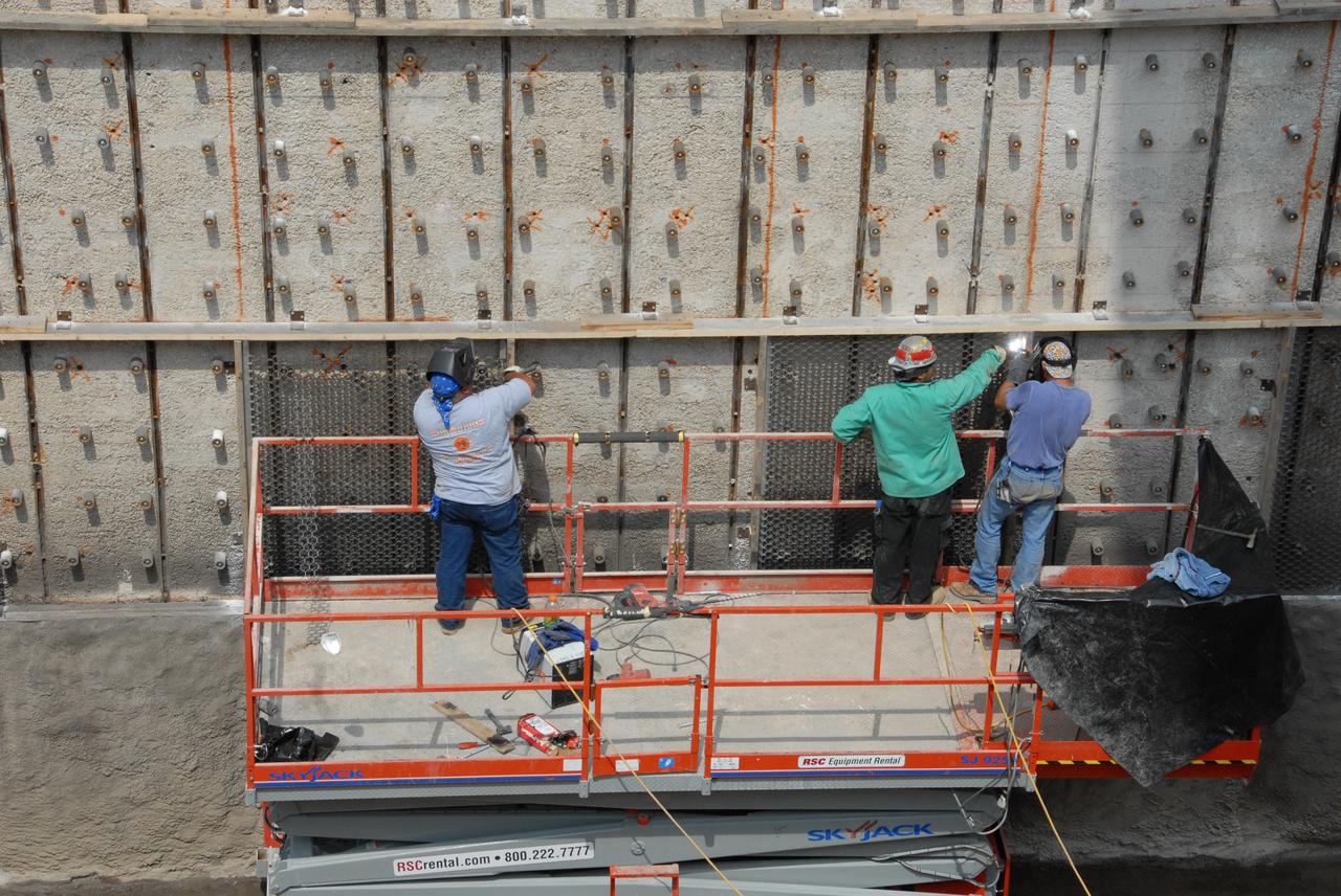
CAPE CANAVERAL, Fla. – Workers weld a steel grid structure to the wall of the flame trench on Launch Pad 39A at NASA's Kennedy Space Center. Damage to the trench occurred during the launch of Discovery on the STS-124 mission. A 75- by 20-foot section of the east wall was destroyed and debris scattered as far as the pad perimeter fence. Repairs are expected to be completed before the targeted Oct. 8 launch of Atlantis on the NASA Hubble Space Telescope servicing mission. Photo credit: NASA/Jack Pfaller
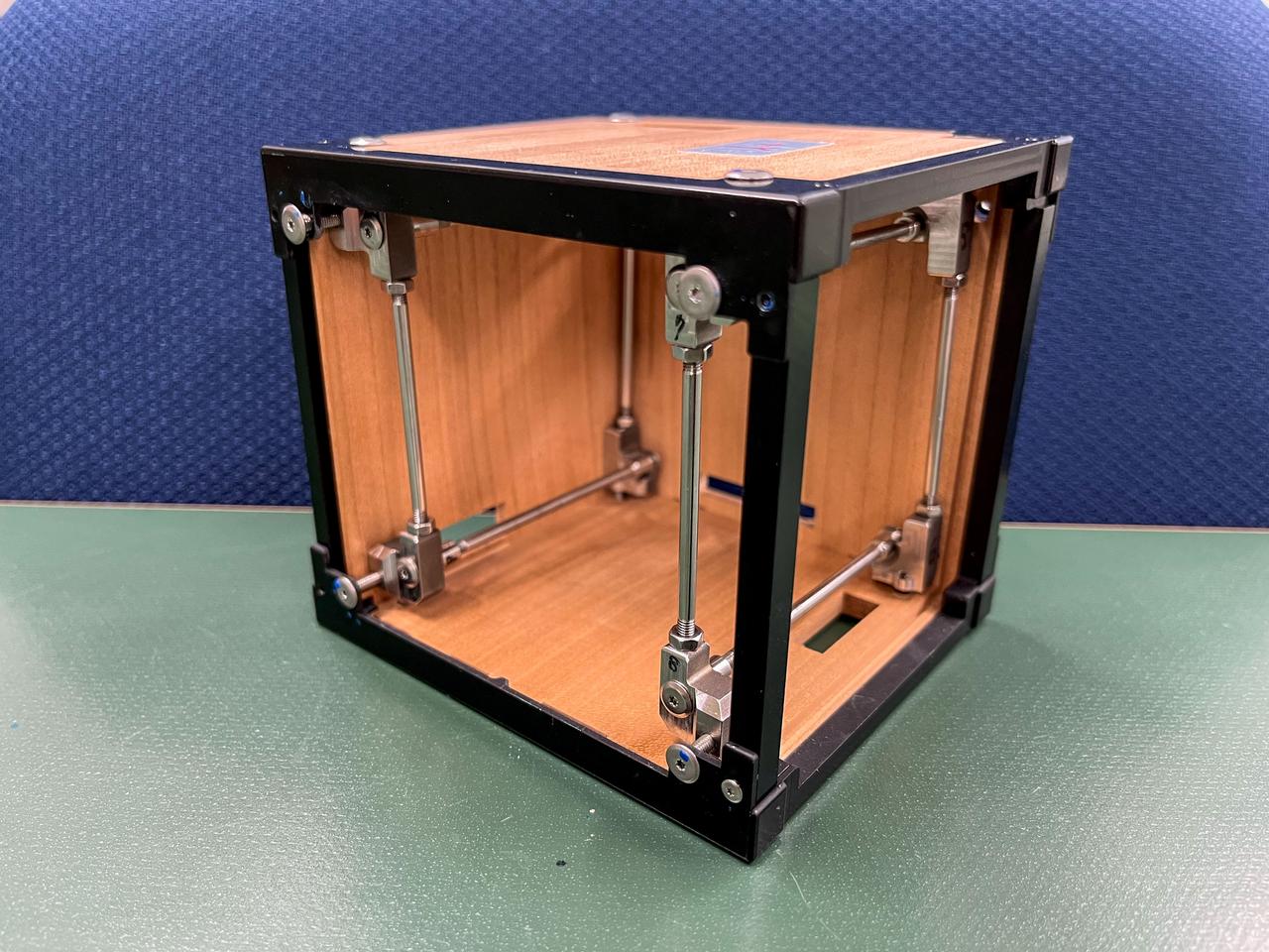
jsc2024e081749 (3/18/2023) --- LignoSat structural internal view shows the relationship among wooden panels, aluminum frames, and stainless steel shafts. LignoSat is the world’s first wooden satellite and investigates how wood changes in the space environment, as well as how wood transmits data through geomagnetic fields and wood’s resistance to cosmic radiation. Image courtesy of Kyoto University.
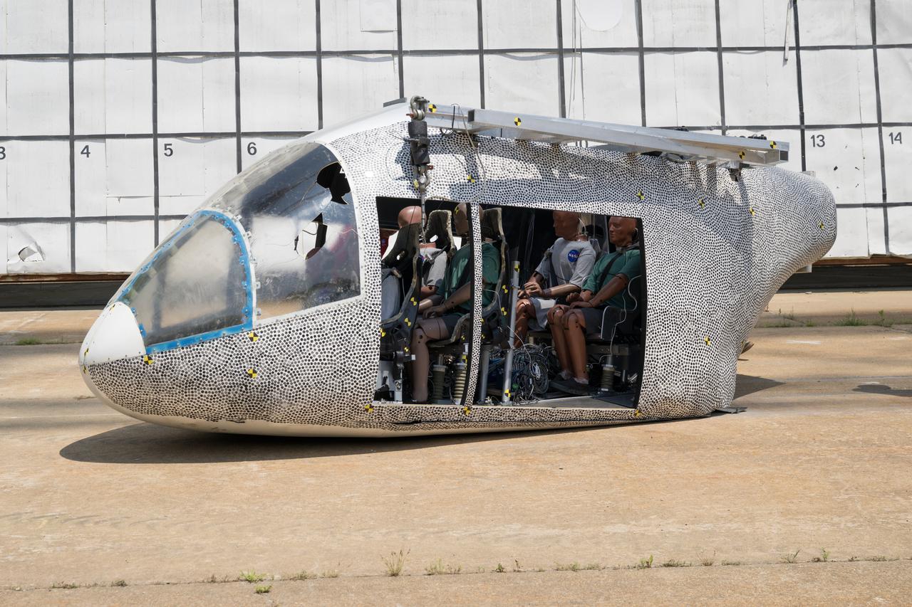
An aircraft body modeled after an air taxi with weighted test dummies inside is shown after a drop test at NASA’s Langley Research Center in Hampton, Virginia. The test was completed June 26 at Langley’s Landing and Impact Research Facility. The aircraft was dropped from a tall steel structure, known as a gantry, after being hoisted about 35 feet in the air by cables. NASA researchers are investigating aircraft materials that best absorb impact forces in a crash.
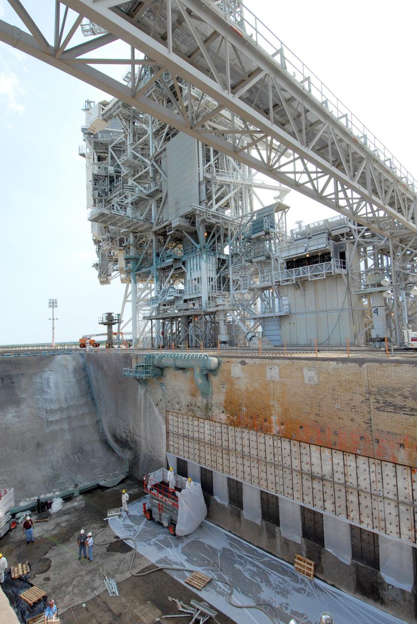
CAPE CANAVERAL, Fla. – This elevated view shows workers on a platform welding a steel grid structure to the wall of the flame trench on Launch Pad 39A at NASA's Kennedy Space Center. Damage to the trench occurred during the launch of Discovery on the STS-124 mission. A 75- by 20-foot section of the east wall was destroyed and debris scattered as far as the pad perimeter fence. Repairs are expected to be completed before the targeted Oct. 8 launch of Atlantis on the NASA Hubble Space Telescope servicing mission. Photo credit: NASA/Jack Pfaller

An aircraft body modeled after an air taxi with weighted test dummies inside is being prepared for a drop test by researchers at NASA’s Langley Research Center in Hampton, Virginia. The test was completed June 26 at Langley’s Landing and Impact Research Facility. The aircraft was dropped from a tall steel structure, known as a gantry, after being hoisted about 35 feet in the air by cables. NASA researchers are investigating aircraft materials that best absorb impact forces in a crash.
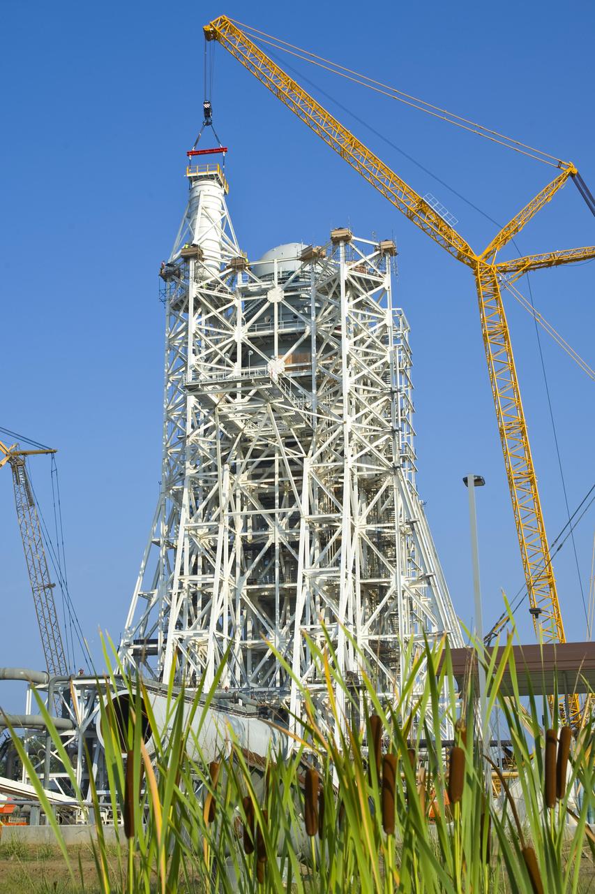
Stennis Space Center employees marked another construction milestone July 25 with installation of the 85,000-gallon liquid hydrogen tank atop the A-3 Test Stand. The 300-foot-tall stand is being built to test next-generation rocket engines that could carry humans into deep space once more. The liquid hydrogen tank and a 35,000-gallon liquid oxygen tank installed atop the steel structure earlier in June will provide fuel propellants for testing the engines.
CAPE CANAVERAL, Fla. – Workers prepare to weld a steel grid structure to the wall of the flame trench on Launch Pad 39A at NASA's Kennedy Space Center. Damage to the trench occurred during the launch of Discovery on the STS-124 mission. A 75- by 20-foot section of the east wall was destroyed and debris scattered as far as the pad perimeter fence. Repairs are expected to be completed before the targeted Oct. 8 launch of Atlantis on the NASA Hubble Space Telescope servicing mission. Photo credit: NASA/Jack Pfaller
CAPE CANAVERAL, Fla. – Workers weld a steel grid structure to the wall of the flame trench on Launch Pad 39A at NASA's Kennedy Space Center. Damage to the trench occurred during the launch of Discovery on the STS-124 mission. A 75- by 20-foot section of the east wall was destroyed and debris scattered as far as the pad perimeter fence. Repairs are expected to be completed before the targeted Oct. 8 launch of Atlantis on the NASA Hubble Space Telescope servicing mission. Photo credit: NASA/Jack Pfaller

A sliver of the Moon is visible just before sunrise at NASA's Kennedy Space Center in Florida. In view is one of the steel structures of the mobile launcher (ML). Several launch umbilicals have been installed on the ML tower. Exploration Ground Systems is overseeing installation of umbilicals and launch accessories on the ML to prepare for the first integrated test flight of the Orion spacecraft on the agency's Space Launch System rocket on Exploration Mission-1.

Instructor Rob Mortin watches as Stennis Space Center firefighters Lt. Greg Lampley, Rodney Boone, Vance Forrest and Billy Scarborough practice high-angle rope rescue techniques during a May 11, 2012, training exercise. The exercise specifically focused on scenarios applicable to the 300-foot-tall, open-steel-structure A-3 Test Stand under construction at the rocket engine test facility.
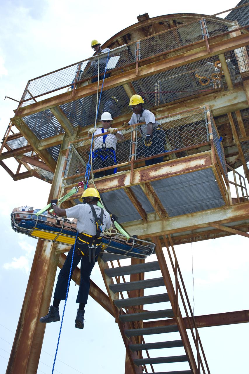
Instructor Rob Mortin watches as Stennis Space Center firefighters Lt. Greg Lampley, Rodney Boone, Vance Forrest and Billy Scarborough practice high-angle rope rescue techniques during a May 11, 2012, training exercise. The exercise specifically focused on scenarios applicable to the 300-foot-tall, open-steel-structure A-3 Test Stand under construction at the rocket engine test facility.
Construction of the A-3 Test Stand at Stennis Space Center continued June 8 with installation of a 35,000-gallon liquid oxygen tank atop the steel structure. The stand is being built to test next-generation rocket engines that will carry humans into deep space once more. The LOX tank and a liquid hydrogen tank to be installed atop the stand later will provide propellants for testing the engines. The A-3 Test Stand is scheduled for completion and activation in 2013.
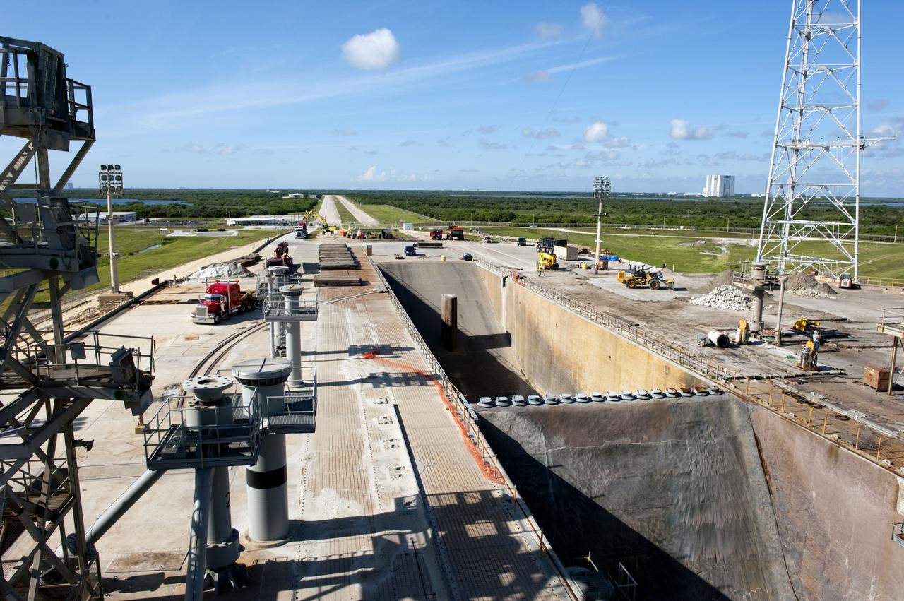
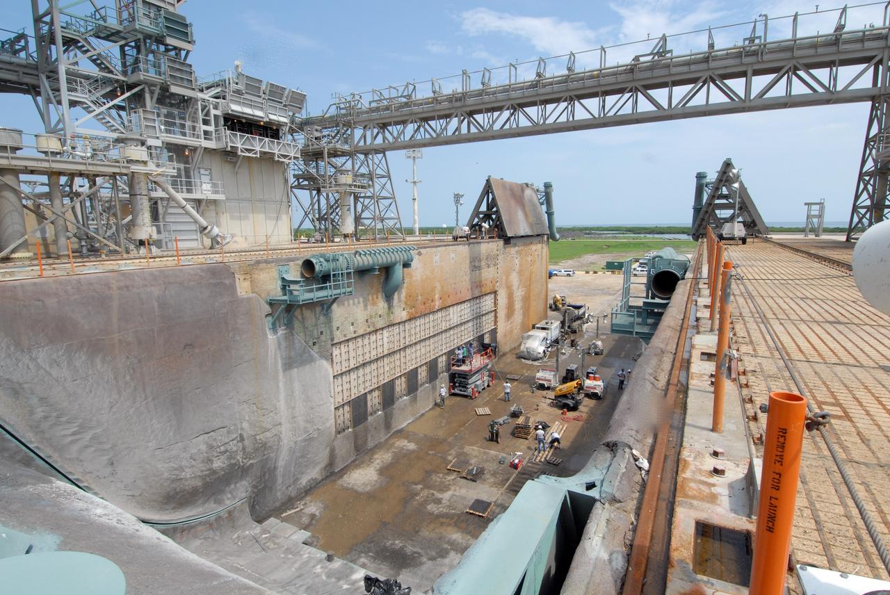
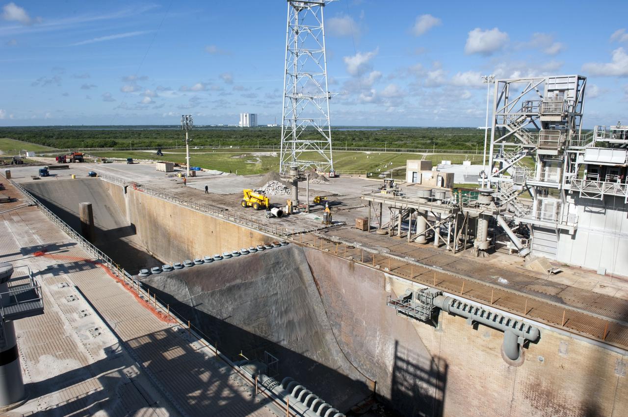
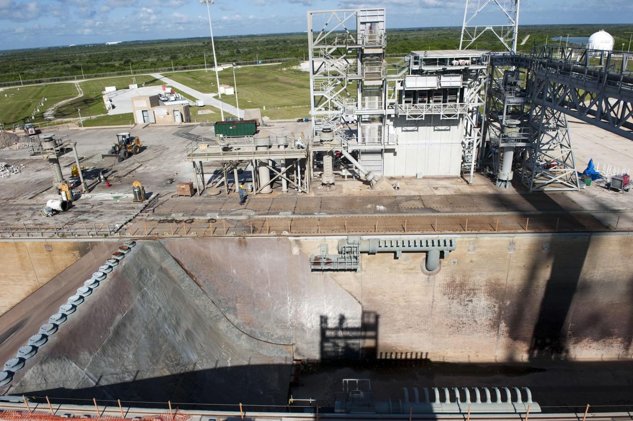
CAPE CANAVERAL, Fla. -- At NASA's Kennedy Space Center in Florida, cleanup of Launch Pad 39B is in progress beside the pad's flame trench. The trench is 450 feet long, 58 feet wide and 42 feet deep with an inner inverted V-shaped steel flame deflector. Sand, reinforcing steel and large wooden mats were placed over the pad's concrete surfaces during deconstruction to protect them from falling debris. In the distance is the 525-foot-tall Vehicle Assembly Building. In 2009, the structure at the pad was no longer needed for NASA's Space Shuttle Program, so it is being restructured for future use. The new design will feature a "clean pad" for rockets to come with their own launcher, making it more versatile for a number of rockets and spacecraft. The lightning protection system, consisting of three lightning towers and a wire catenary system, will remain. For information on NASA's future plans, visit http://www.nasa.gov/exploration. Photo credit: NASA/Kim Shiflett
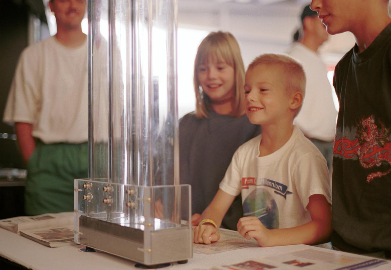
An entranced youngster watches a demonstration of the enhanced resilience of undercooled metal alloys as compared to conventional alloys. Steel bearings are dropped onto plates made of steel, titanium alloy, and zirconium liquid metal alloy, so-called because its molecular structure is amorphous and not crystalline. The bearing on the liquid metal plate bounces for a minute or more longer than on the other plates. Experiments aboard the Space Shuttle helped scientists refine their understanding of the physical properties of certain metal alloys when undercooled (i.e., kept liquid below their normal solidification temperature). This new knowledge then allowed scientists to modify a terrestrial production method so they can now make limited quantities marketed under the Liquid Metal trademark. The exhibit was a part of the NASA outreach activity at AirVenture 2000 sponsored by the Experimental Aircraft Association in Oshkosh, WI.
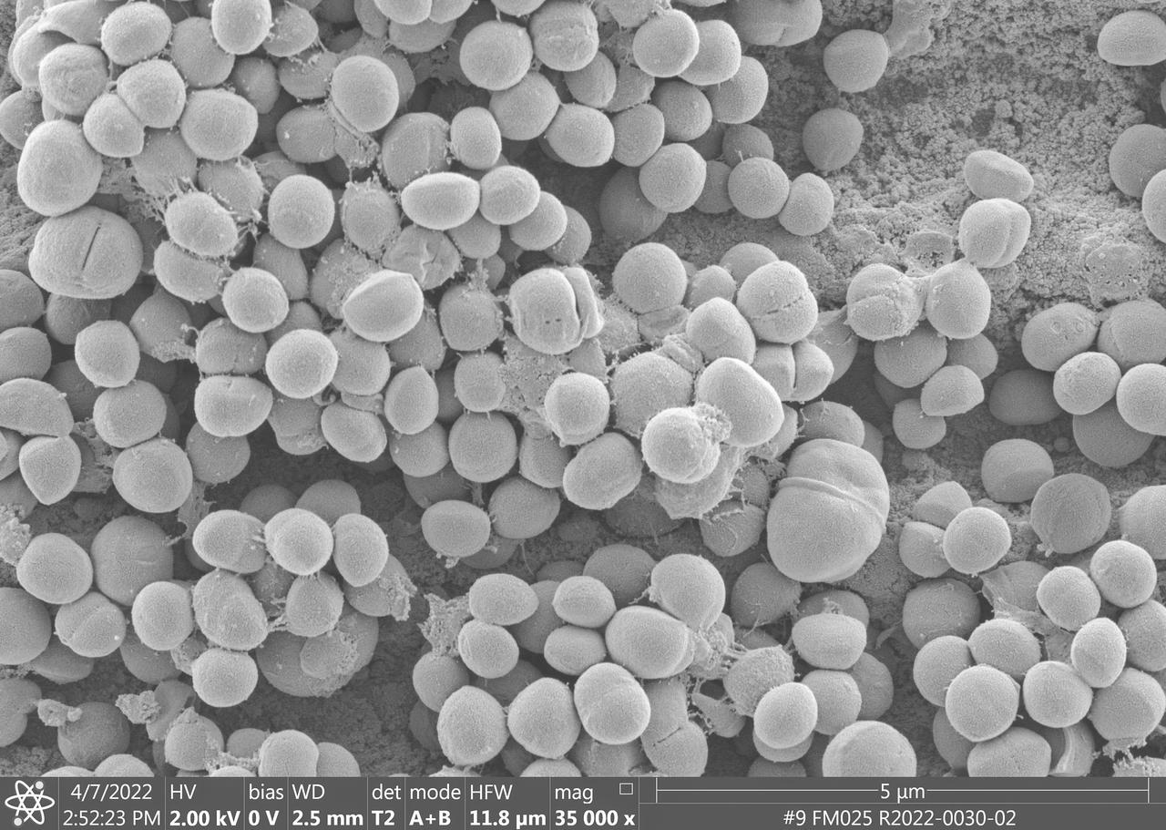
jsc2023e010178 (4/7/2022) --- This image taken by a scanning electron microscope shows one of the ESA-Biofilms sample plates from its first launch to the International Space Station. The sample plate in this image is made of stainless steel, which is the reference surface in the experiment since it has no antimicrobial properties. This surface also has a 3 µm laser structure engraved to the surface as control. In contrast to the copper surface, there are many Staphylococcus capitis cells attached to the steel surface that are actively dividing and starting to from components of a biofilm matrix. The ESA-Biofilms investigation studies bacterial biofilm formation and antimicrobial properties of different metal surfaces under spaceflight conditions in altered gravity. Image courtesy of DLR, CC BY-NC-ND 3.0.
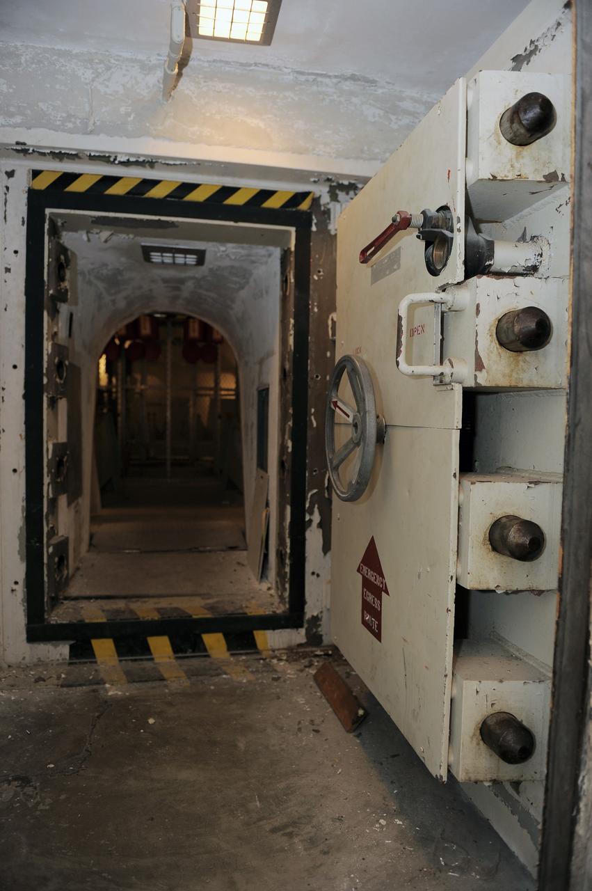
CAPE CANAVERAL, Fla. -- A steel door, similar to a bank vault door, leads to the blast-resistant "rubber room" beneath Launch Pad 39B at NASA's Kennedy Space Center. The room is a steel dome floating on rubber isolators and was used as an escape route during the Apollo Program in case of an emergency. It has since been abandoned by astronauts, but throughout the years nature found its way inside, including raccoons, snakes, birds and even a bobcat and opossum. Starting in 2009, the structure above the room on the pad was no longer needed for NASA's Space Shuttle Program, so it is being restructured for future use. The new design will feature a "clean pad" for rockets to come with their own launcher, making it more versatile for a number of vehicles. For information on NASA's future plans, visit www.nasa.gov. Photo credit: NASA/Kim Shiflett
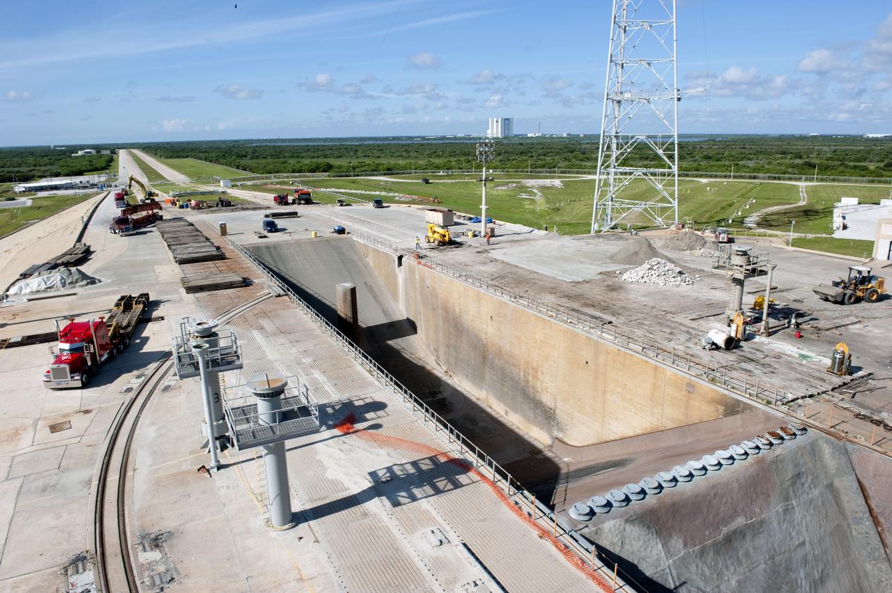
CAPE CANAVERAL, Fla. -- At NASA's Kennedy Space Center in Florida, cleanup of Launch Pad 39B is in progress beside the pad's flame trench. The trench is 450 feet long, 58 feet wide and 42 feet deep with an inner inverted V-shaped steel flame deflector. Sand, reinforcing steel and large wooden mats were placed over the pad's concrete surfaces during deconstruction to protect them from falling debris. In the distance is the 525-foot-tall Vehicle Assembly Building. In 2009, the structure at the pad was no longer needed for NASA's Space Shuttle Program, so it is being restructured for future use. The new design will feature a "clean pad" for rockets to come with their own launcher, making it more versatile for a number of rockets and spacecraft. The lightning protection system, consisting of three lightning towers and a wire catenary system, will remain. For information on NASA's future plans, visit http://www.nasa.gov/exploration. Photo credit: NASA/Kim Shiflett
CAPE CANAVERAL, Fla. -- At NASA's Kennedy Space Center in Florida, cleanup of Launch Pad 39B is in progress beside the pad's flame trench. The trench is 450 feet long, 58 feet wide and 42 feet deep with an inner inverted V-shaped steel flame deflector. Sand, reinforcing steel and large wooden mats were placed over the pad's concrete surfaces during deconstruction to protect them from falling debris. In the distance is the 525-foot-tall Vehicle Assembly Building. In 2009, the structure at the pad was no longer needed for NASA's Space Shuttle Program, so it is being restructured for future use. The new design will feature a "clean pad" for rockets to come with their own launcher, making it more versatile for a number of rockets and spacecraft. The lightning protection system, consisting of three lightning towers and a wire catenary system, will remain. For information on NASA's future plans, visit http://www.nasa.gov/exploration. Photo credit: NASA/Kim Shiflett
CAPE CANAVERAL, Fla. -- At NASA's Kennedy Space Center in Florida, cleanup of Launch Pad 39B is in progress beside the pad's flame trench. The trench is 450 feet long, 58 feet wide and 42 feet deep with an inner inverted V-shaped steel flame deflector. Sand, reinforcing steel and large wooden mats were placed over the pad's concrete surfaces during deconstruction to protect them from falling debris. In 2009, the structure at the pad was no longer needed for NASA's Space Shuttle Program, so it is being restructured for future use. The new design will feature a "clean pad" for rockets to come with their own launcher, making it more versatile for a number of rockets and spacecraft. The lightning protection system, consisting of three lightning towers and a wire catenary system, will remain. For information on NASA's future plans, visit http://www.nasa.gov/exploration. Photo credit: NASA/Kim Shiflett

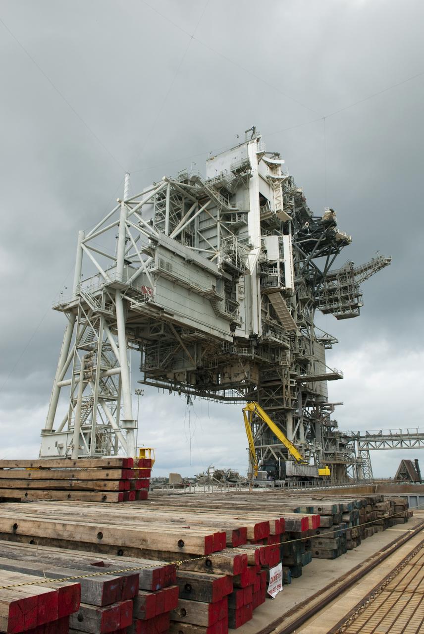
CAPE CANAVERAL, Fla. -- At NASA's Kennedy Space Center in Florida, this image shows the progress of the rotating service structure (RSS) on Launch Pad 39B as it is being dismantled. Sand, reinforcing steel and large wooden mats were put down under the RSS to protect the structure's concrete from falling debris during deconstruction. Starting in 2009, the structure at the pad was no longer needed for NASA's Space Shuttle Program, so it is being restructured for future use. The new design will feature a "clean pad" for rockets to come with their own launcher, making it more versatile for a number of vehicles. The new lightning protection system, consisting of three lightning towers and a wire catenary system will remain. Photo credit: NASA/Jack Pfaller
CAPE CANAVERAL, Fla. -- At NASA's Kennedy Space Center in Florida, this long range view shows the progress of the rotating service structure (RSS) on Launch Pad 39B as it is being dismantled. Sand, reinforcing steel and large wooden mats were put down under the RSS to protect the structure's concrete from falling debris during deconstruction. Starting in 2009, the structure at the pad was no longer needed for NASA's Space Shuttle Program, so it is being restructured for future use. The new design will feature a "clean pad" for rockets to come with their own launcher, making it more versatile for a number of vehicles. The new lightning protection system, consisting of three lightning towers and a wire catenary system will remain. Photo credit: NASA/Jack Pfaller
CAPE CANAVERAL, Fla. -- At NASA's Kennedy Space Center in Florida, this image shows the progress of the rotating service structure (RSS) on Launch Pad 39B as it is being dismantled. Sand, reinforcing steel and large wooden mats were put down under the RSS to protect the structure's concrete from falling debris during deconstruction. Starting in 2009, the structure at the pad was no longer needed for NASA's Space Shuttle Program, so it is being restructured for future use. The new design will feature a "clean pad" for rockets to come with their own launcher, making it more versatile for a number of vehicles. The new lightning protection system, consisting of three lightning towers and a wire catenary system will remain. Photo credit: NASA/Jack Pfaller
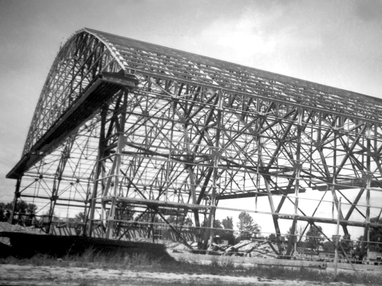
Northward view of the Flight Research Building's steel framework in August 1941 as it neared completion at the National Advisory Committee for Aeronautics (NACA) Aircraft Engine Research Laboratory. The 272- by 150-foot hangar had a 90-foot clearance at its highest point. The hangar was the first structure built and was needed as a shelter for the growing staff, who occupied a nearby Farm House at this point. In January 1941 the Cleveland-area R.P. Carbone Construction Company was selected to build the hangar. Over the ensuing months, however, the NACA management became frustrated by the slow progress on the project. Although Carbone was contracted to complete the entire hangar by August, it was September before even the structural steel frame, seen in this photograph, was in place. Officials estimated the roof and siding were four months behind schedule. This was a serious concern because the lab’s research, support and administrative staff members would soon begin arriving. By mid-September the transite walls began enclosing the skeleton. In October work began on the temporary offices inside. The building was completed in mid-December just in time for the staff arriving from Langley.
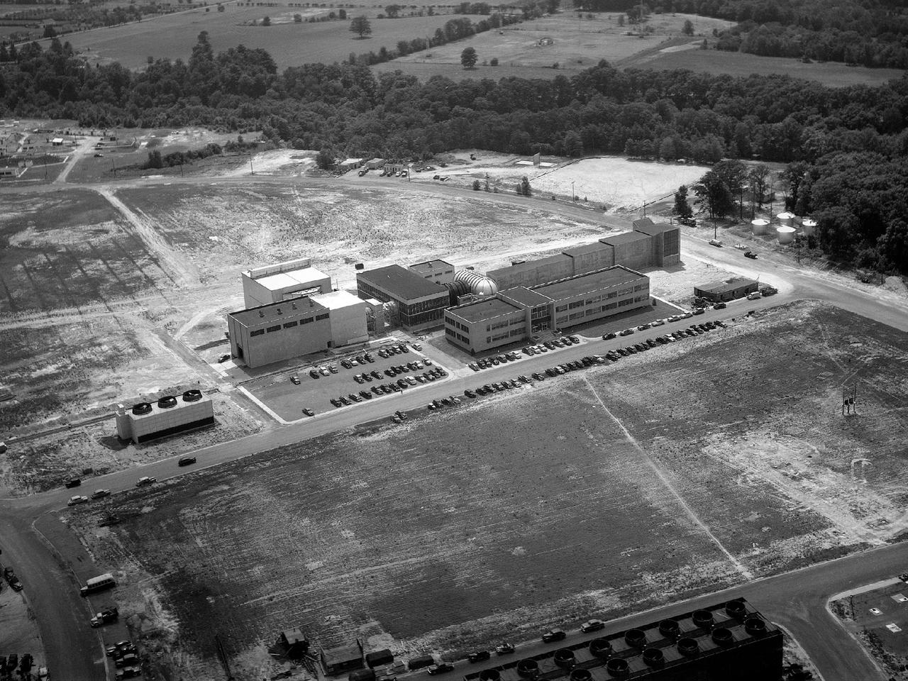
Aerial view of the 8- by 6-Foot Supersonic Wind Tunnel in its original configuration at the National Advisory Committee for Aeronautics (NACA) Lewis Flight Propulsion Laboratory. The 8- by 6 was the laboratory’s first large supersonic wind tunnel. It was also the NACA’s most powerful supersonic tunnel, and its first facility capable of running an engine at supersonic speeds. The 8- by 6-foot tunnel has been used to study inlets and exit nozzles, fuel injectors, flameholders, exit nozzles, and controls on ramjet and turbojet propulsion systems. The 8- by 6 was originally an open-throat and non-return tunnel. This meant that the supersonic air flow was blown through the test section and out the other end into the atmosphere. In this photograph, the three drive motors in the structure at the left supplied power to the seven-stage axial-flow compressor in the light-colored structure. The air flow passed through flexible walls which were bent to create the desired speed. The test article was located in the 8- by 6-foot stainless steel test section located inside the steel pressure chamber at the center of this photograph. The tunnel dimensions were then gradually increased to slow the air flow before it exited into the atmosphere. The large two-story building in front of the tunnel was used as office space for the researchers.
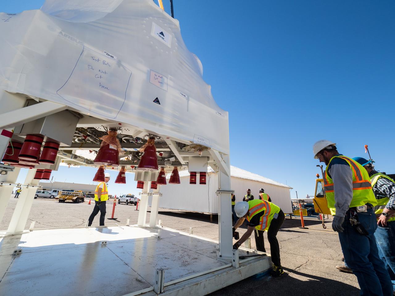
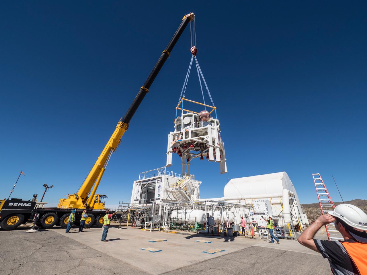
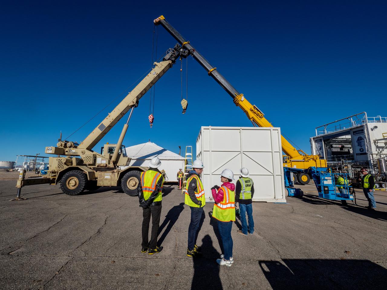
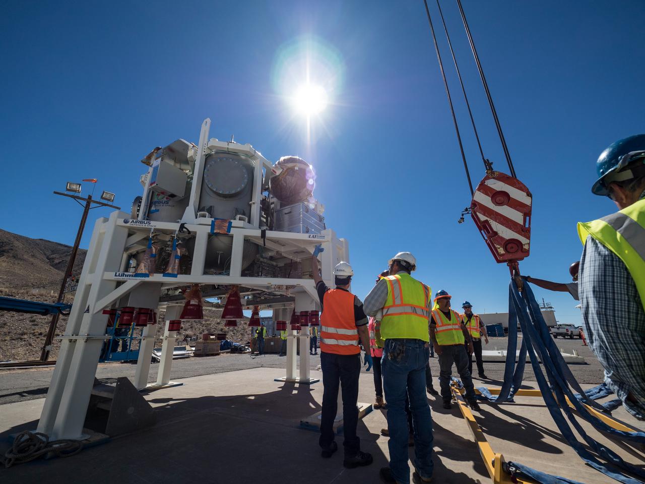
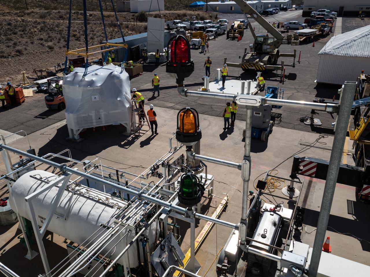
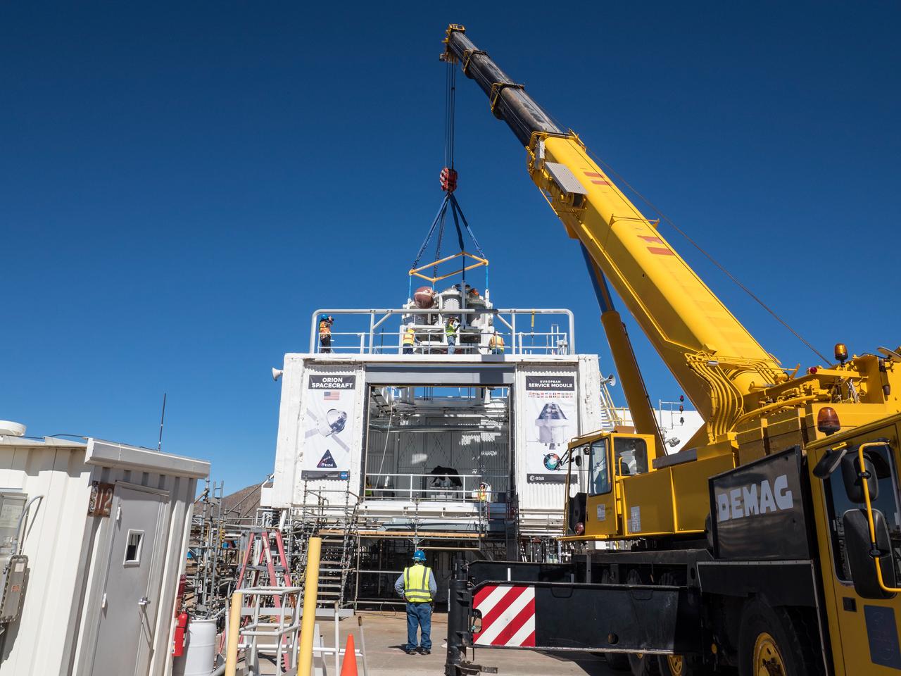
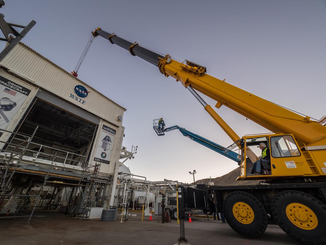
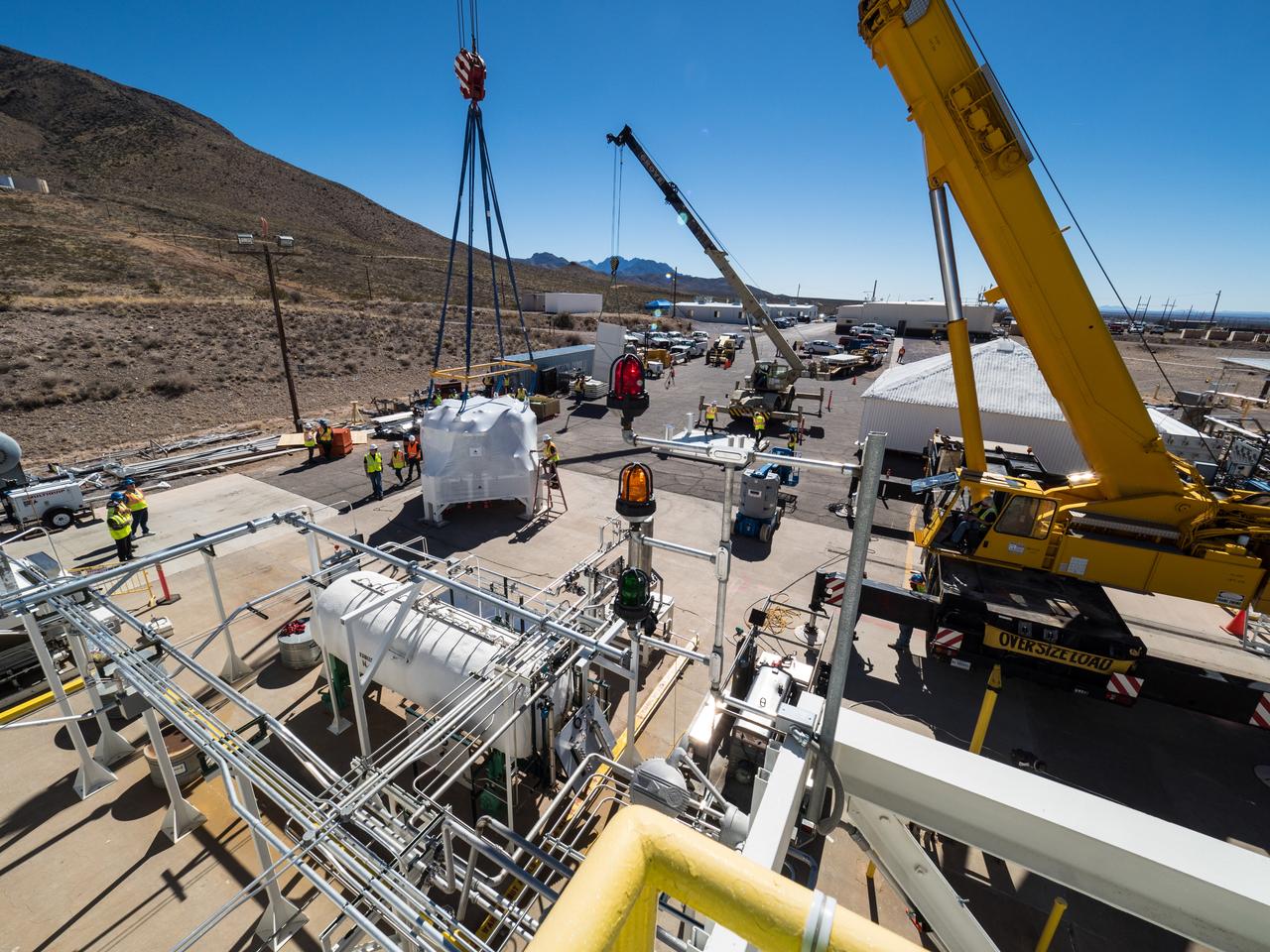
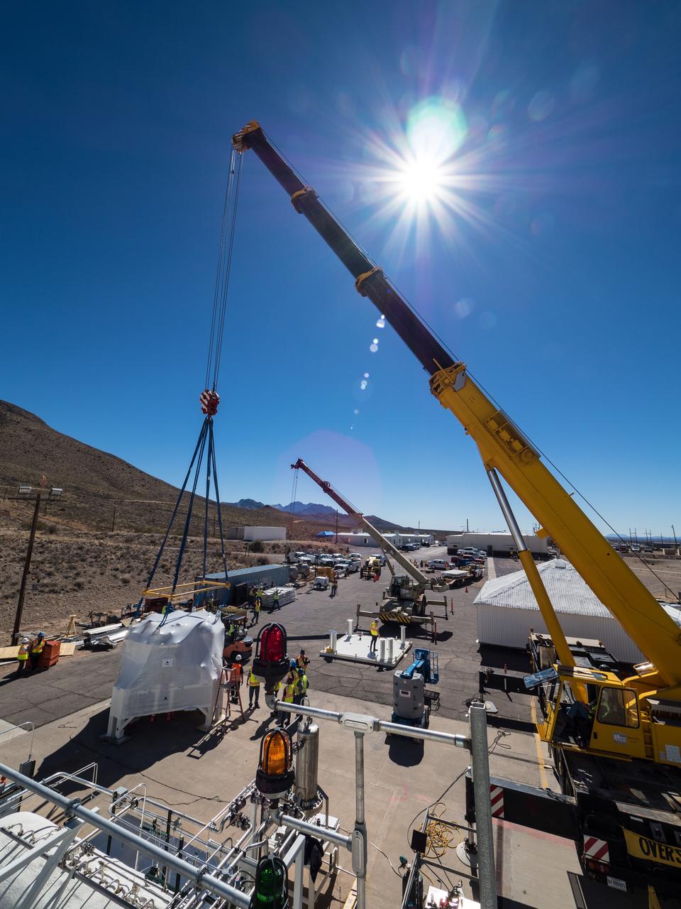
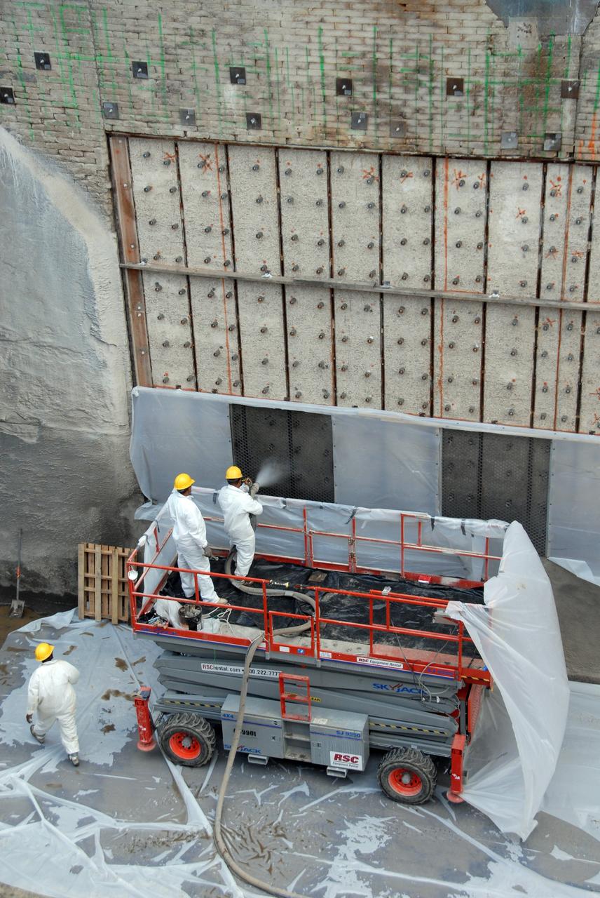
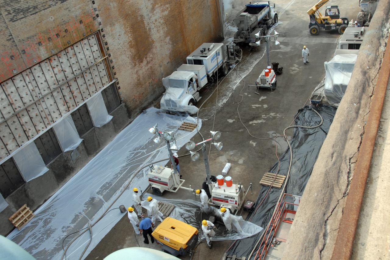
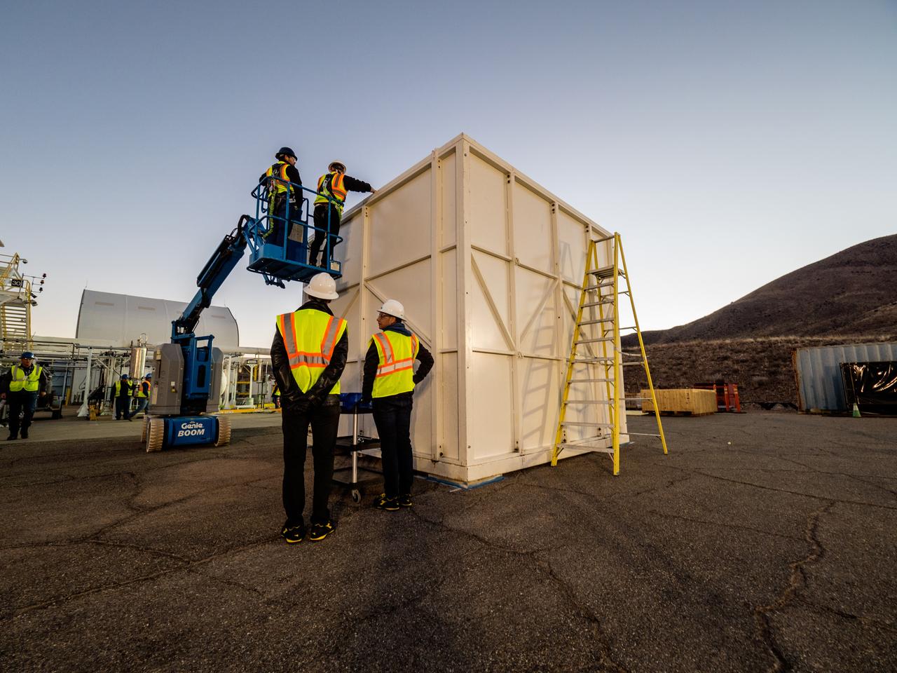
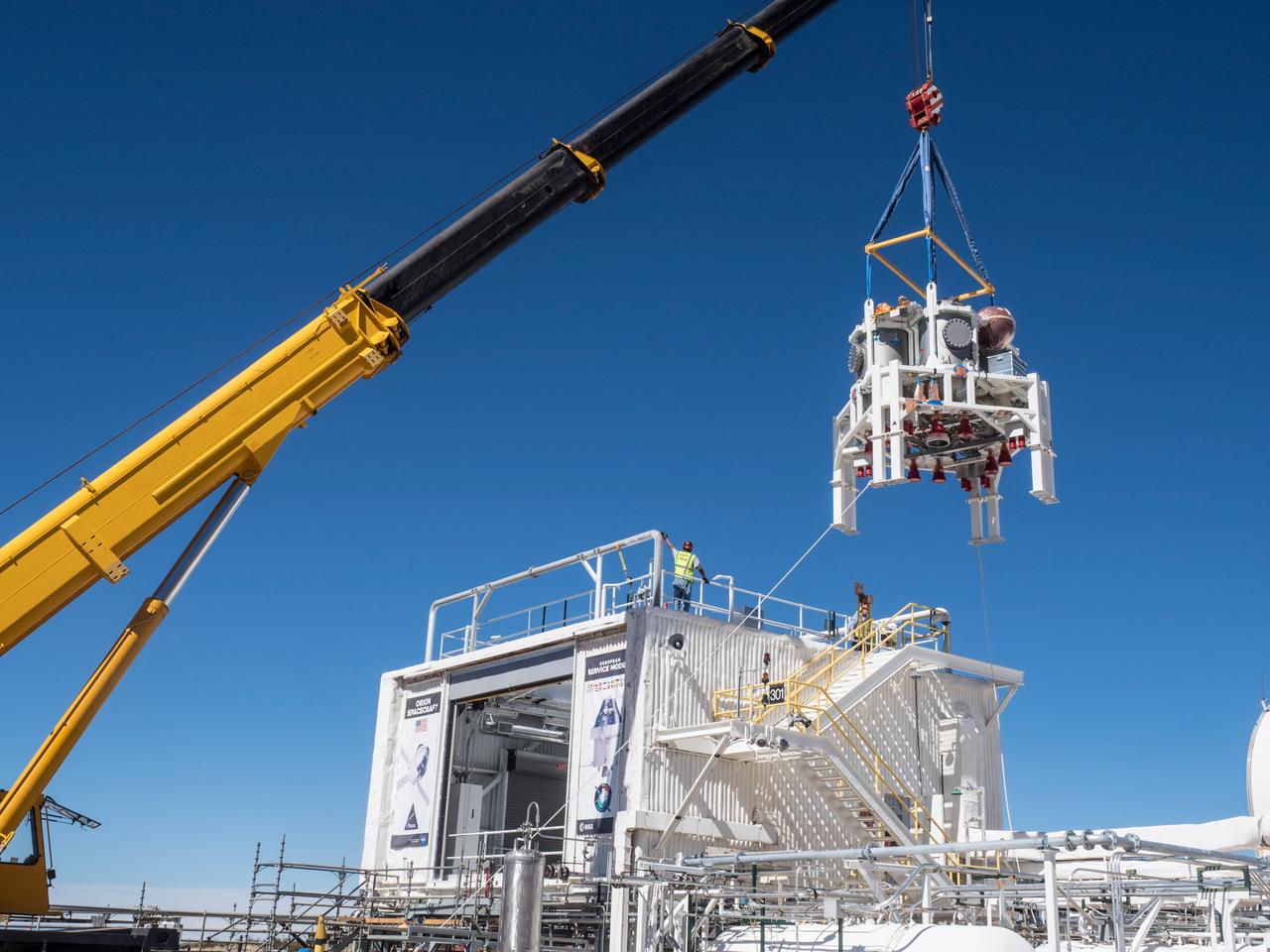
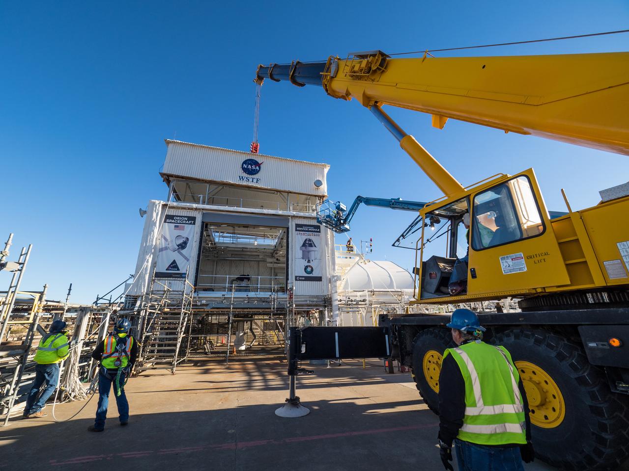
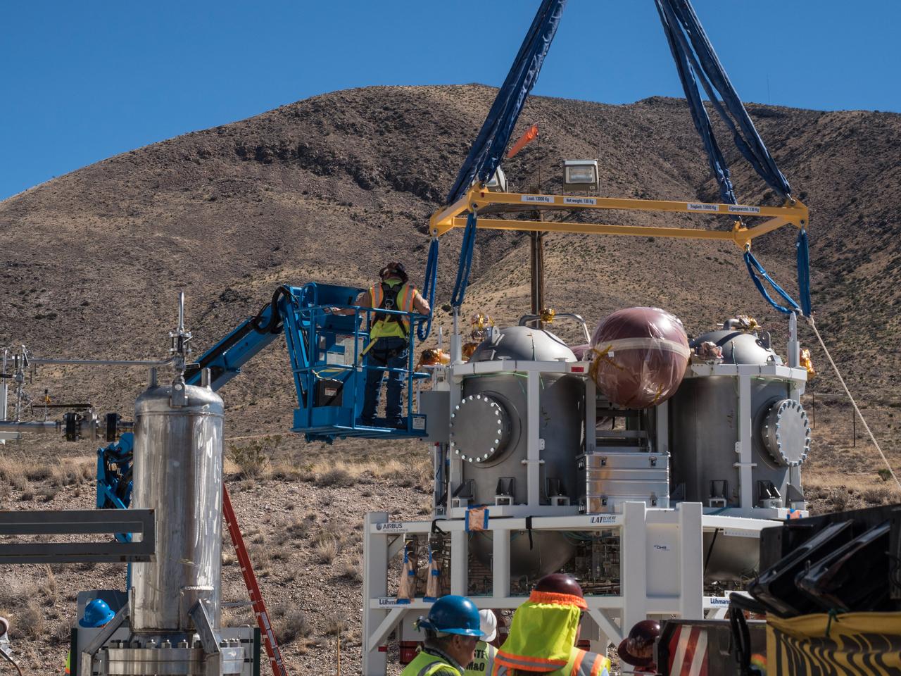
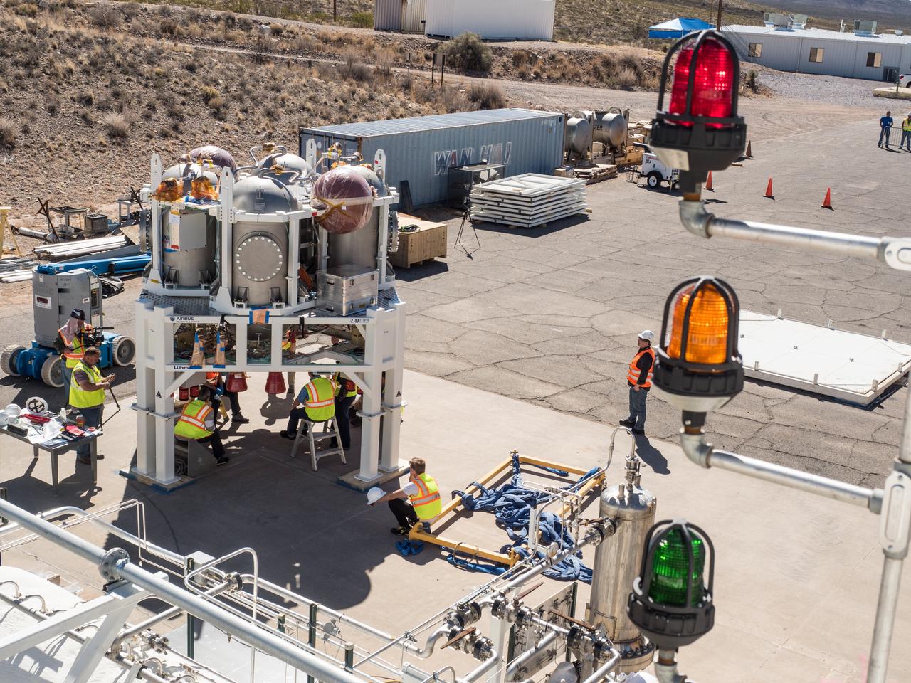
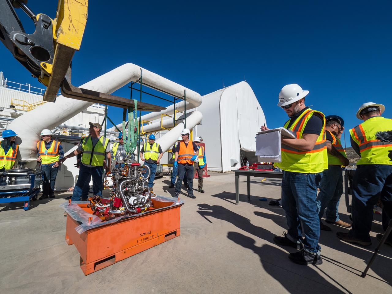
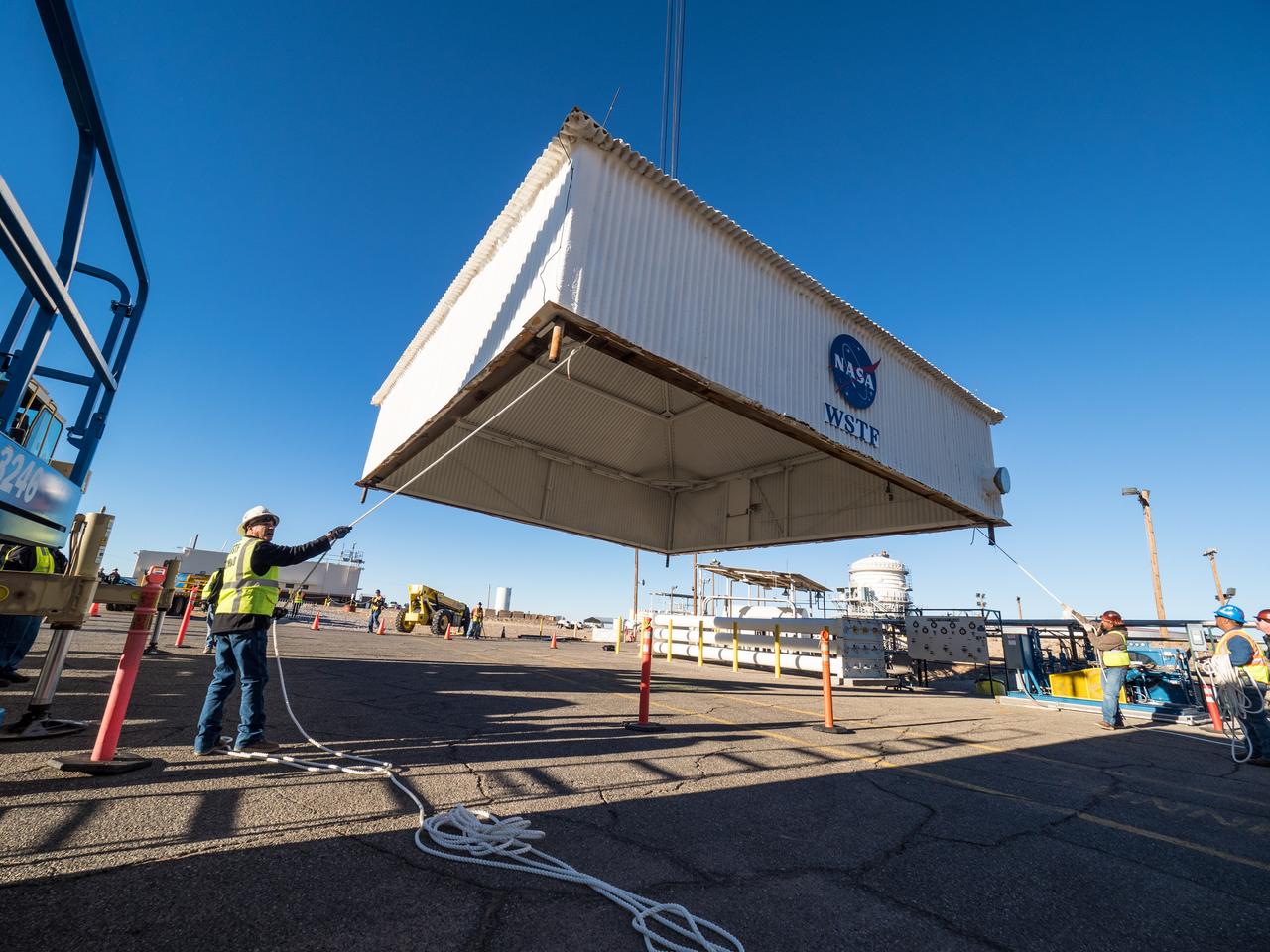
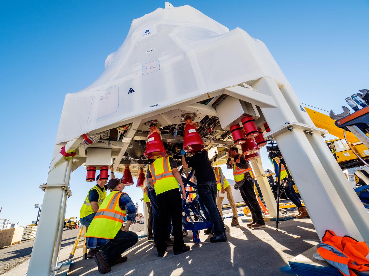
On Feb. 21, 2017 engineers successfully install ESA’s European Service Module Propulsion Qualification Module (PQM) at NASA’s White Sands Test Facility in New Mexico that was delivered by Airbus – ESA’s prime contractor for the Service Module. The module will be equipped with a total of 21 engines to support NASA’s Orion spacecraft: one U.S. Space Shuttle Orbital Maneuvering System (OMS) engine, eight auxiliary thrusters and 12 smaller thrusters produced by Airbus Safran Launchers in Germany. The all-steel PQM structure is used to test the propulsion systems on Orion, including “hot firing” of the OMS engine and thrusters.
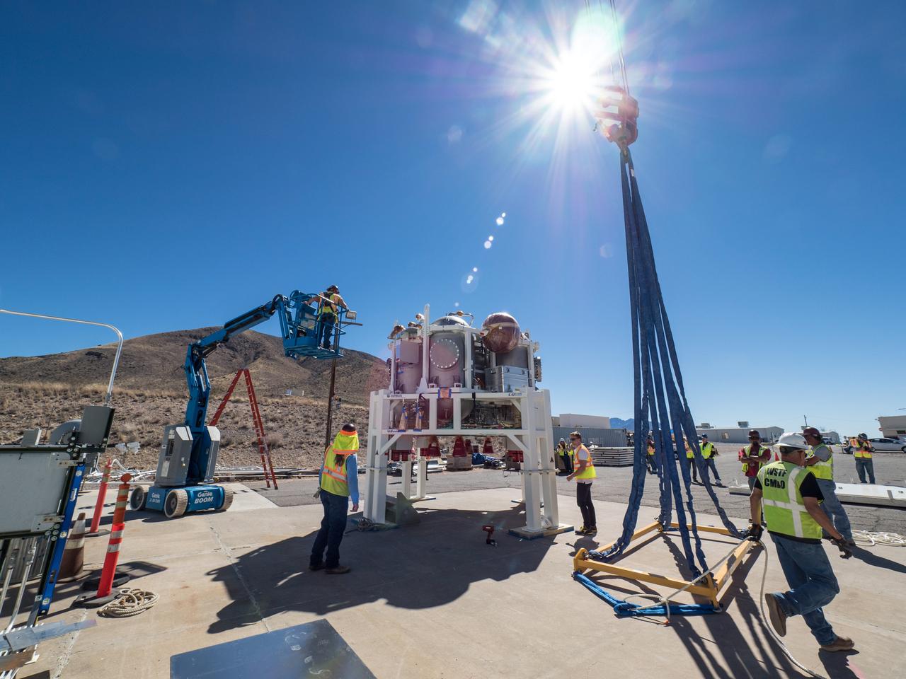
On Feb. 22, engineers successfully install ESA’s European Service Module Propulsion Qualification Module (PQM) at NASA’s White Sands Test Facility in New Mexico that was delivered by Airbus – ESA’s prime contractor for the Service Module. The module will be equipped with a total of 21 engines to support NASA’s Orion spacecraft: one U.S. Space Shuttle Orbital Maneuvering System (OMS) engine, eight auxiliary thrusters and 12 smaller thrusters produced by Airbus Safran Launchers in Germany. The all-steel PQM structure is used to test the propulsion systems on Orion, including “hot firing” of the OMS engine and thrusters.
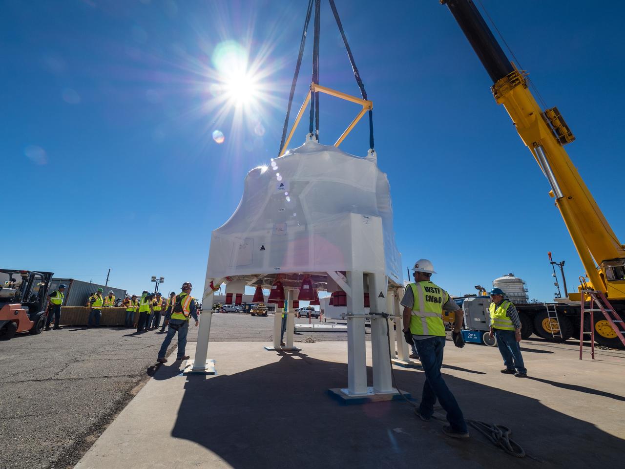
On Feb. 22, engineers successfully install ESA’s European Service Module Propulsion Qualification Module (PQM) at NASA’s White Sands Test Facility in New Mexico that was delivered by Airbus – ESA’s prime contractor for the Service Module. The module will be equipped with a total of 21 engines to support NASA’s Orion spacecraft: one U.S. Space Shuttle Orbital Maneuvering System (OMS) engine, eight auxiliary thrusters and 12 smaller thrusters produced by Airbus Safran Launchers in Germany. The all-steel PQM structure is used to test the propulsion systems on Orion, including “hot firing” of the OMS engine and thrusters.
On Feb. 21, 2017 engineers successfully install ESA’s European Service Module Propulsion Qualification Module (PQM) at NASA’s White Sands Test Facility in New Mexico that was delivered by Airbus – ESA’s prime contractor for the Service Module. The module will be equipped with a total of 21 engines to support NASA’s Orion spacecraft: one U.S. Space Shuttle Orbital Maneuvering System (OMS) engine, eight auxiliary thrusters and 12 smaller thrusters produced by Airbus Safran Launchers in Germany. The all-steel PQM structure is used to test the propulsion systems on Orion, including “hot firing” of the OMS engine and thrusters.
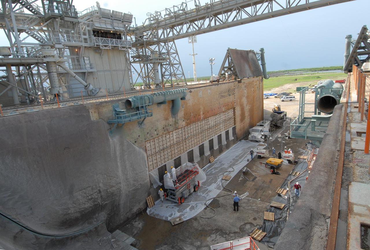
CAPE CANAVERAL, Fla. – This elevated view of Launch Pad 39A at NASA's Kennedy Space Center shows workers preparing to fill steel grid structures, welded to the wall of the flame trench, with a heat-resistant concrete called Fondue Fyre, developed during NASA's Apollo lunar program. Damage to the trench occurred during the May 31 launch of Discovery on the STS-124 mission. A 75- by 20-foot section of the east wall was destroyed and debris scattered as far as the pad perimeter fence. Repairs are expected to be completed before the targeted Oct. 8 launch of Atlantis on the NASA Hubble Space Telescope servicing mission. Photo credit: NASA/Jack Pfaller
On Feb. 21, 2017 engineers successfully install ESA’s European Service Module Propulsion Qualification Module (PQM) at NASA’s White Sands Test Facility in New Mexico that was delivered by Airbus – ESA’s prime contractor for the Service Module. The module will be equipped with a total of 21 engines to support NASA’s Orion spacecraft: one U.S. Space Shuttle Orbital Maneuvering System (OMS) engine, eight auxiliary thrusters and 12 smaller thrusters produced by Airbus Safran Launchers in Germany. The all-steel PQM structure is used to test the propulsion systems on Orion, including “hot firing” of the OMS engine and thrusters.
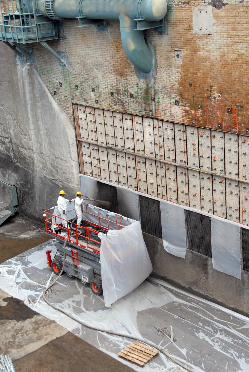
CAPE CANAVERAL, Fla. – At Launch Pad 39A at NASA's Kennedy Space Center, workers on a platform spray a heat-resistant concrete called Fondue Fyre into steel grid structures, welded to the wall of the flame trench. Fondue Fyre was developed during NASA's Apollo lunar program. Damage to the trench occurred during the May 31 launch of Discovery on the STS-124 mission. A 75- by 20-foot section of the east wall was destroyed and debris scattered as far as the pad perimeter fence. Repairs are expected to be completed before the targeted Oct. 8 launch of Atlantis on the NASA Hubble Space Telescope servicing mission. Photo credit: NASA/Jack Pfaller
On Feb. 22, engineers successfully install ESA’s European Service Module Propulsion Qualification Module (PQM) at NASA’s White Sands Test Facility in New Mexico that was delivered by Airbus – ESA’s prime contractor for the Service Module. The module will be equipped with a total of 21 engines to support NASA’s Orion spacecraft: one U.S. Space Shuttle Orbital Maneuvering System (OMS) engine, eight auxiliary thrusters and 12 smaller thrusters produced by Airbus Safran Launchers in Germany. The all-steel PQM structure is used to test the propulsion systems on Orion, including “hot firing” of the OMS engine and thrusters.
CAPE CANAVERAL, Fla. – This elevated view of Launch Pad 39A at NASA's Kennedy Space Center shows workers preparing to fill steel grid structures, welded to the wall of the flame trench, with a heat-resistant concrete called Fondue Fyre, developed during NASA's Apollo lunar program. Damage to the trench occurred during the May 31 launch of Discovery on the STS-124 mission. A 75- by 20-foot section of the east wall was destroyed and debris scattered as far as the pad perimeter fence. Repairs are expected to be completed before the targeted Oct. 8 launch of Atlantis on the NASA Hubble Space Telescope servicing mission. Photo credit: NASA/Jack Pfaller

CAPE CANAVERAL, Fla. – At Launch Pad 39A at NASA's Kennedy Space Center, workers spray a heat-resistant concrete called Fondue Fyre into steel grid structures, welded to the wall of the flame trench. Fondue Fyre was developed during NASA's Apollo lunar program. Damage to the trench occurred during the May 31 launch of Discovery on the STS-124 mission. A 75- by 20-foot section of the east wall was destroyed and debris scattered as far as the pad perimeter fence. Repairs are expected to be completed before the targeted Oct. 8 launch of Atlantis on the NASA Hubble Space Telescope servicing mission. Photo credit: NASA/Jack Pfaller
On Feb. 21, 2017 engineers successfully install ESA’s European Service Module Propulsion Qualification Module (PQM) at NASA’s White Sands Test Facility in New Mexico that was delivered by Airbus – ESA’s prime contractor for the Service Module. The module will be equipped with a total of 21 engines to support NASA’s Orion spacecraft: one U.S. Space Shuttle Orbital Maneuvering System (OMS) engine, eight auxiliary thrusters and 12 smaller thrusters produced by Airbus Safran Launchers in Germany. The all-steel PQM structure is used to test the propulsion systems on Orion, including “hot firing” of the OMS engine and thrusters.
On Feb. 22, engineers successfully install ESA’s European Service Module Propulsion Qualification Module (PQM) at NASA’s White Sands Test Facility in New Mexico that was delivered by Airbus – ESA’s prime contractor for the Service Module. The module will be equipped with a total of 21 engines to support NASA’s Orion spacecraft: one U.S. Space Shuttle Orbital Maneuvering System (OMS) engine, eight auxiliary thrusters and 12 smaller thrusters produced by Airbus Safran Launchers in Germany. The all-steel PQM structure is used to test the propulsion systems on Orion, including “hot firing” of the OMS engine and thrusters.
On Feb. 21, 2017 engineers successfully install ESA’s European Service Module Propulsion Qualification Module (PQM) at NASA’s White Sands Test Facility in New Mexico that was delivered by Airbus – ESA’s prime contractor for the Service Module. The module will be equipped with a total of 21 engines to support NASA’s Orion spacecraft: one U.S. Space Shuttle Orbital Maneuvering System (OMS) engine, eight auxiliary thrusters and 12 smaller thrusters produced by Airbus Safran Launchers in Germany. The all-steel PQM structure is used to test the propulsion systems on Orion, including “hot firing” of the OMS engine and thrusters.

On Feb. 21, 2017 engineers successfully install ESA’s European Service Module Propulsion Qualification Module (PQM) at NASA’s White Sands Test Facility in New Mexico that was delivered by Airbus – ESA’s prime contractor for the Service Module. The module will be equipped with a total of 21 engines to support NASA’s Orion spacecraft: one U.S. Space Shuttle Orbital Maneuvering System (OMS) engine, eight auxiliary thrusters and 12 smaller thrusters produced by Airbus Safran Launchers in Germany. The all-steel PQM structure is used to test the propulsion systems on Orion, including “hot firing” of the OMS engine and thrusters.
CAPE CANAVERAL, Fla. -- At NASA's Kennedy Space Center in Florida, the flame trench remains at Launch Pad 39B after the pad's deconstruction. The trench is 450 feet long, 58 feet wide and 42 feet deep with an inner inverted V-shaped steel flame deflector. In 2009, the structure at the pad was no longer needed for NASA's Space Shuttle Program, so it is being restructured for future use. The new design will feature a "clean pad" for rockets to come with their own launcher, making it more versatile for a number of vehicles. For information on NASA's future plans, visit http://www.nasa.gov/exploration. Photo credit: NASA/Kim Shiflett
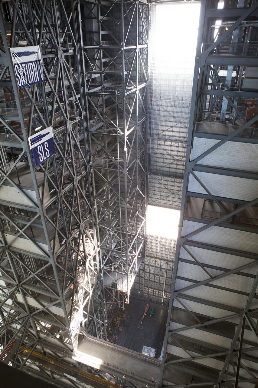
CAPE CANAVERAL, Fla. – A view looking down from one of the higher levels in the Vehicle Assembly Building, or VAB, reveals High Bay 3 at NASA’s Kennedy Space Center in Florida. Banners note the heights of the Saturn V, Space Launch System, or SLS, and shuttle on the steel structure. Modifications are underway to prepare High Bay 3 for a new platform system. The modifications are part of a centerwide refurbishment initiative under the Ground Systems Development and Operations Program. High bay 3 is being refurbished to accommodate NASA’s Space Launch System and a variety of other spacecraft. For more information, visit http://www.nasa.gov/exploration/systems/ground/index.html. Photo credit: NASA/Dimitri Gerondidakis
CAPE CANAVERAL, Fla. -- At NASA's Kennedy Space Center in Florida, the flame trench remains at Launch Pad 39B after the pad's deconstruction. The trench is 450 feet long, 58 feet wide and 42 feet deep with an inner inverted V-shaped steel flame deflector. In 2009, the structure at the pad was no longer needed for NASA's Space Shuttle Program, so it is being restructured for future use. The new design will feature a "clean pad" for rockets to come with their own launcher, making it more versatile for a number of vehicles. For information on NASA's future plans, visit http://www.nasa.gov/exploration. Photo credit: NASA/Kim Shiflett

On Feb. 22, engineers successfully install ESA’s European Service Module Propulsion Qualification Module (PQM) at NASA’s White Sands Test Facility in New Mexico that was delivered by Airbus – ESA’s prime contractor for the Service Module. The module will be equipped with a total of 21 engines to support NASA’s Orion spacecraft: one U.S. Space Shuttle Orbital Maneuvering System (OMS) engine, eight auxiliary thrusters and 12 smaller thrusters produced by Airbus Safran Launchers in Germany. The all-steel PQM structure is used to test the propulsion systems on Orion, including “hot firing” of the OMS engine and thrusters.
On Feb. 21, 2017 engineers successfully install ESA’s European Service Module Propulsion Qualification Module (PQM) at NASA’s White Sands Test Facility in New Mexico that was delivered by Airbus – ESA’s prime contractor for the Service Module. The module will be equipped with a total of 21 engines to support NASA’s Orion spacecraft: one U.S. Space Shuttle Orbital Maneuvering System (OMS) engine, eight auxiliary thrusters and 12 smaller thrusters produced by Airbus Safran Launchers in Germany. The all-steel PQM structure is used to test the propulsion systems on Orion, including “hot firing” of the OMS engine and thrusters.
On Feb. 21, 2017 engineers successfully install ESA’s European Service Module Propulsion Qualification Module (PQM) at NASA’s White Sands Test Facility in New Mexico that was delivered by Airbus – ESA’s prime contractor for the Service Module. The module will be equipped with a total of 21 engines to support NASA’s Orion spacecraft: one U.S. Space Shuttle Orbital Maneuvering System (OMS) engine, eight auxiliary thrusters and 12 smaller thrusters produced by Airbus Safran Launchers in Germany. The all-steel PQM structure is used to test the propulsion systems on Orion, including “hot firing” of the OMS engine and thrusters.
CAPE CANAVERAL, Fla. – This elevated view of Launch Pad 39A at NASA's Kennedy Space Center shows workers filling steel grid structures, welded to the wall of the flame trench, with a heat-resistant concrete called Fondue Fyre, developed during NASA's Apollo lunar program. Damage to the trench occurred during the May 31 launch of Discovery on the STS-124 mission. A 75- by 20-foot section of the east wall was destroyed and debris scattered as far as the pad perimeter fence. Repairs are expected to be completed before the targeted Oct. 8 launch of Atlantis on the NASA Hubble Space Telescope servicing mission. Photo credit: NASA/Jack Pfaller
CAPE CANAVERAL, Fla. – This elevated view of Launch Pad 39A at NASA's Kennedy Space Center shows the steel grid structures, welded to the wall of the flame trench, which workers will be filling with a heat-resistant concrete called Fondue Fyre, developed during NASA's Apollo lunar program. Damage to the trench occurred during the May 31 launch of Discovery on the STS-124 mission. A 75- by 20-foot section of the east wall was destroyed and debris scattered as far as the pad perimeter fence. Repairs are expected to be completed before the targeted Oct. 8 launch of Atlantis on the NASA Hubble Space Telescope servicing mission. Photo credit: NASA/Jack Pfaller
On Feb. 21, 2017 engineers successfully install ESA’s European Service Module Propulsion Qualification Module (PQM) at NASA’s White Sands Test Facility in New Mexico that was delivered by Airbus – ESA’s prime contractor for the Service Module. The module will be equipped with a total of 21 engines to support NASA’s Orion spacecraft: one U.S. Space Shuttle Orbital Maneuvering System (OMS) engine, eight auxiliary thrusters and 12 smaller thrusters produced by Airbus Safran Launchers in Germany. The all-steel PQM structure is used to test the propulsion systems on Orion, including “hot firing” of the OMS engine and thrusters.

On Feb. 21, 2017 engineers successfully install ESA’s European Service Module Propulsion Qualification Module (PQM) at NASA’s White Sands Test Facility in New Mexico that was delivered by Airbus – ESA’s prime contractor for the Service Module. The module will be equipped with a total of 21 engines to support NASA’s Orion spacecraft: one U.S. Space Shuttle Orbital Maneuvering System (OMS) engine, eight auxiliary thrusters and 12 smaller thrusters produced by Airbus Safran Launchers in Germany. The all-steel PQM structure is used to test the propulsion systems on Orion, including “hot firing” of the OMS engine and thrusters.
On Feb. 22, engineers successfully install ESA’s European Service Module Propulsion Qualification Module (PQM) at NASA’s White Sands Test Facility in New Mexico that was delivered by Airbus – ESA’s prime contractor for the Service Module. The module will be equipped with a total of 21 engines to support NASA’s Orion spacecraft: one U.S. Space Shuttle Orbital Maneuvering System (OMS) engine, eight auxiliary thrusters and 12 smaller thrusters produced by Airbus Safran Launchers in Germany. The all-steel PQM structure is used to test the propulsion systems on Orion, including “hot firing” of the OMS engine and thrusters.
CAPE CANAVERAL, Fla. -- At NASA's Kennedy Space Center in Florida, cleanup of Launch Pad 39B is in progress. Sand, reinforcing steel and large wooden mats were placed over the pad's concrete surfaces during deconstruction to protect them from falling debris. In 2009, the structure at the pad was no longer needed for NASA's Space Shuttle Program, so it is being restructured for future use. The new design will feature a "clean pad" for rockets to come with their own launcher, making it more versatile for a number of vehicles. For information on NASA's future plans, visit http://www.nasa.gov/exploration. Photo credit: NASA/Kim Shiflett
On Feb. 21, 2017 engineers successfully install ESA’s European Service Module Propulsion Qualification Module (PQM) at NASA’s White Sands Test Facility in New Mexico that was delivered by Airbus – ESA’s prime contractor for the Service Module. The module will be equipped with a total of 21 engines to support NASA’s Orion spacecraft: one U.S. Space Shuttle Orbital Maneuvering System (OMS) engine, eight auxiliary thrusters and 12 smaller thrusters produced by Airbus Safran Launchers in Germany. The all-steel PQM structure is used to test the propulsion systems on Orion, including “hot firing” of the OMS engine and thrusters.
On Feb. 22, engineers successfully install ESA’s European Service Module Propulsion Qualification Module (PQM) at NASA’s White Sands Test Facility in New Mexico that was delivered by Airbus – ESA’s prime contractor for the Service Module. The module will be equipped with a total of 21 engines to support NASA’s Orion spacecraft: one U.S. Space Shuttle Orbital Maneuvering System (OMS) engine, eight auxiliary thrusters and 12 smaller thrusters produced by Airbus Safran Launchers in Germany. The all-steel PQM structure is used to test the propulsion systems on Orion, including “hot firing” of the OMS engine and thrusters.

On Feb. 22, engineers successfully install ESA’s European Service Module Propulsion Qualification Module (PQM) at NASA’s White Sands Test Facility in New Mexico that was delivered by Airbus – ESA’s prime contractor for the Service Module. The module will be equipped with a total of 21 engines to support NASA’s Orion spacecraft: one U.S. Space Shuttle Orbital Maneuvering System (OMS) engine, eight auxiliary thrusters and 12 smaller thrusters produced by Airbus Safran Launchers in Germany. The all-steel PQM structure is used to test the propulsion systems on Orion, including “hot firing” of the OMS engine and thrusters.
On Feb. 22, engineers successfully install ESA’s European Service Module Propulsion Qualification Module (PQM) at NASA’s White Sands Test Facility in New Mexico that was delivered by Airbus – ESA’s prime contractor for the Service Module. The module will be equipped with a total of 21 engines to support NASA’s Orion spacecraft: one U.S. Space Shuttle Orbital Maneuvering System (OMS) engine, eight auxiliary thrusters and 12 smaller thrusters produced by Airbus Safran Launchers in Germany. The all-steel PQM structure is used to test the propulsion systems on Orion, including “hot firing” of the OMS engine and thrusters.
On Feb. 21, 2017 engineers successfully install ESA’s European Service Module Propulsion Qualification Module (PQM) at NASA’s White Sands Test Facility in New Mexico that was delivered by Airbus – ESA’s prime contractor for the Service Module. The module will be equipped with a total of 21 engines to support NASA’s Orion spacecraft: one U.S. Space Shuttle Orbital Maneuvering System (OMS) engine, eight auxiliary thrusters and 12 smaller thrusters produced by Airbus Safran Launchers in Germany. The all-steel PQM structure is used to test the propulsion systems on Orion, including “hot firing” of the OMS engine and thrusters.
On Feb. 21, 2017 engineers successfully install ESA’s European Service Module Propulsion Qualification Module (PQM) at NASA’s White Sands Test Facility in New Mexico that was delivered by Airbus – ESA’s prime contractor for the Service Module. The module will be equipped with a total of 21 engines to support NASA’s Orion spacecraft: one U.S. Space Shuttle Orbital Maneuvering System (OMS) engine, eight auxiliary thrusters and 12 smaller thrusters produced by Airbus Safran Launchers in Germany. The all-steel PQM structure is used to test the propulsion systems on Orion, including “hot firing” of the OMS engine and thrusters.
On Feb. 21, 2017 engineers successfully install ESA’s European Service Module Propulsion Qualification Module (PQM) at NASA’s White Sands Test Facility in New Mexico that was delivered by Airbus – ESA’s prime contractor for the Service Module. The module will be equipped with a total of 21 engines to support NASA’s Orion spacecraft: one U.S. Space Shuttle Orbital Maneuvering System (OMS) engine, eight auxiliary thrusters and 12 smaller thrusters produced by Airbus Safran Launchers in Germany. The all-steel PQM structure is used to test the propulsion systems on Orion, including “hot firing” of the OMS engine and thrusters.