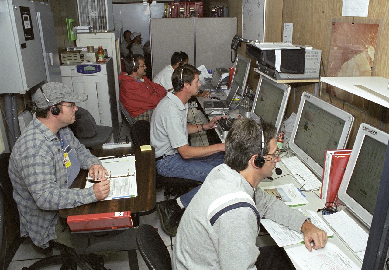
AeroVironment engineers and technicians closely monitor flight data in the ground control station during the Pathfinder-Plus' turbulence measurement flights.
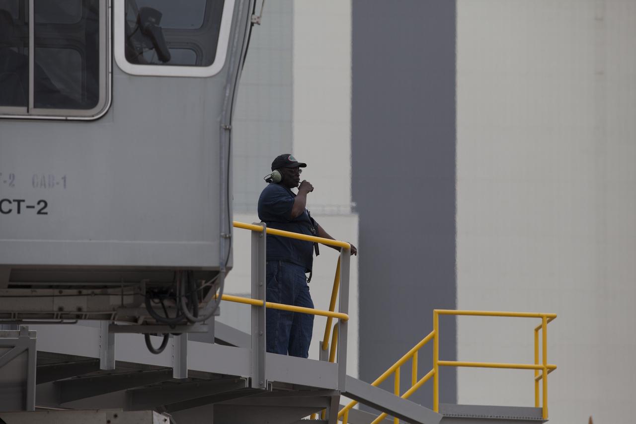
A technician communicates with the driver of NASA’s upgraded crawler-transporter 2 (CT-2) during the return drive to the Vehicle Assembly Building (VAB) at the agency’s Kennedy Space Center in Florida from its test drive to Launch Pad 39B. The crawler’s recently completed upgrades and modifications were tested to ensure the vehicle will be ready to support NASA’s journey to Mars. The Ground Systems Development and Operations Program at Kennedy oversaw upgrades to the crawler in the VAB. The crawler will carry the mobile launcher with Orion atop the Space Launch System rocket to Pad 39B for Exploration Mission 1.
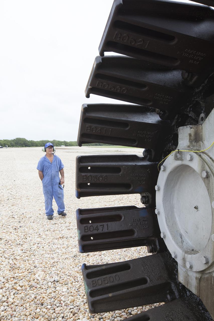
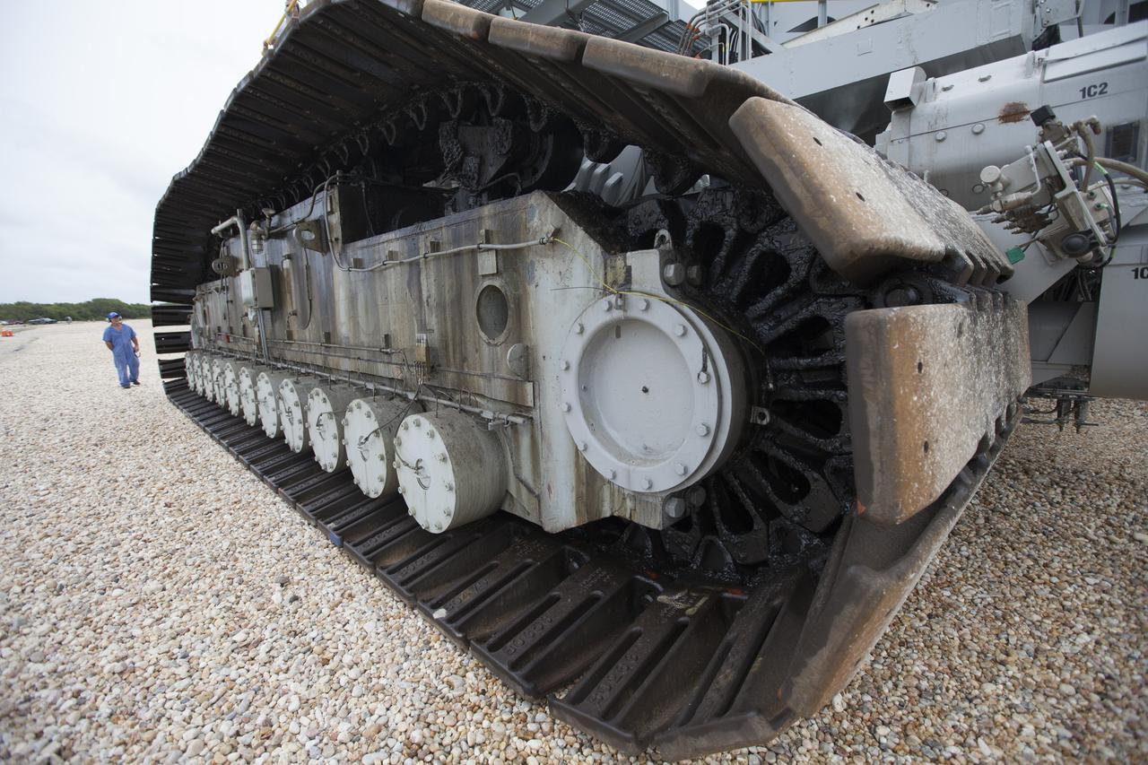
A technician watches the motion of the giant tracks on NASA’s upgraded crawler-transporter 2 (CT-2) as the giant vehicle travels along the crawlerway toward the Vehicle Assembly Building from its trek to Launch Pad 39B at the agency’s Kennedy Space Center in Florida. CT-2 was drive to Pad 39B to test recently completed upgrades and modifications to support NASA’s journey to Mars. The Ground Systems Development and Operations Program at Kennedy oversaw upgrades to the crawler in the VAB. The crawler will carry the mobile launcher with Orion atop the Space Launch System rocket to Pad 39B for Exploration Mission 1.
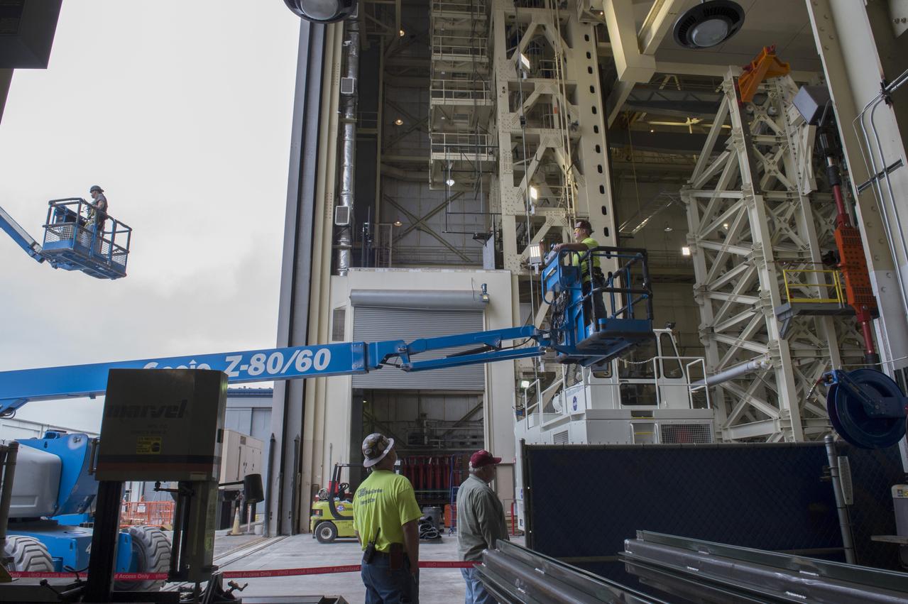
A technician watches the motion of the giant tracks on NASA’s upgraded crawler-transporter 2 (CT-2) as the giant vehicle travels along the crawlerway toward the Vehicle Assembly Building from its trek to Launch Pad 39B at the agency’s Kennedy Space Center in Florida. CT-2 was drive to Pad 39B to test recently completed upgrades and modifications to support NASA’s journey to Mars. The Ground Systems Development and Operations Program at Kennedy oversaw upgrades to the crawler in the VAB. The crawler will carry the mobile launcher with Orion atop the Space Launch System rocket to Pad 39B for Exploration Mission 1.
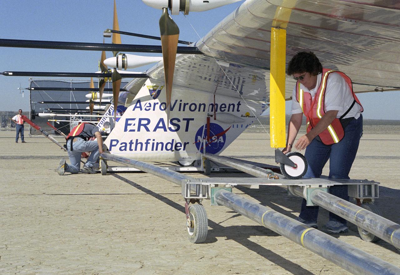
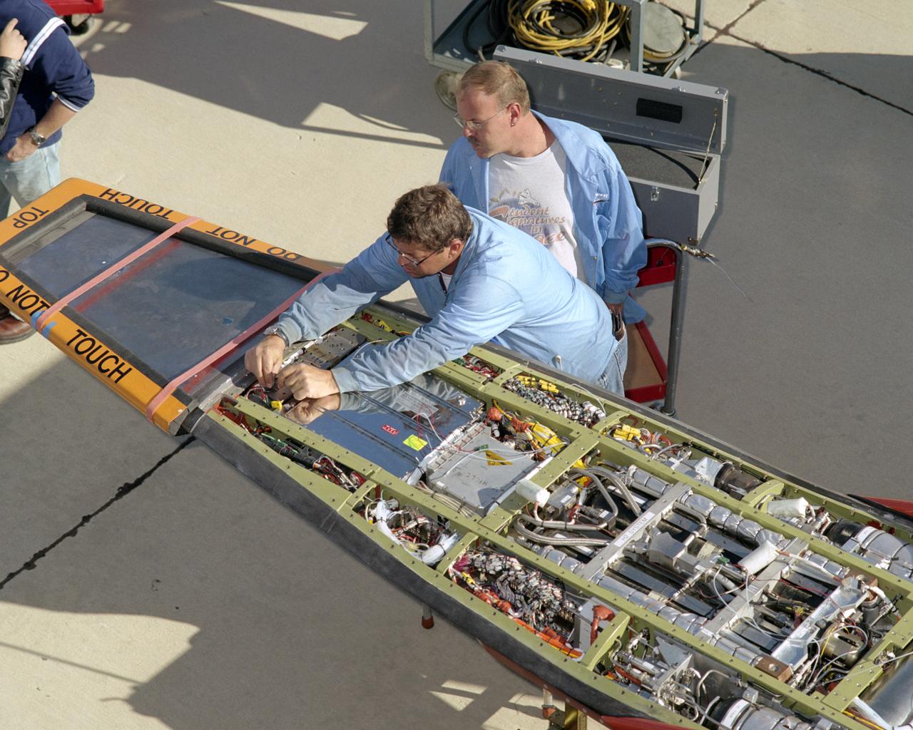
AeroVironment technicians prepare to remove the Pathfinder-Plus solar aircraft from its ground dolly before a turbulence measurement flight from Rogers Dry Lake.
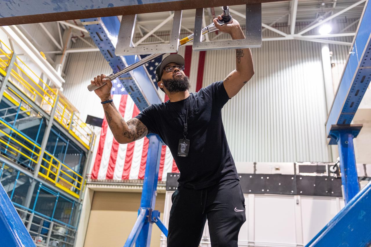
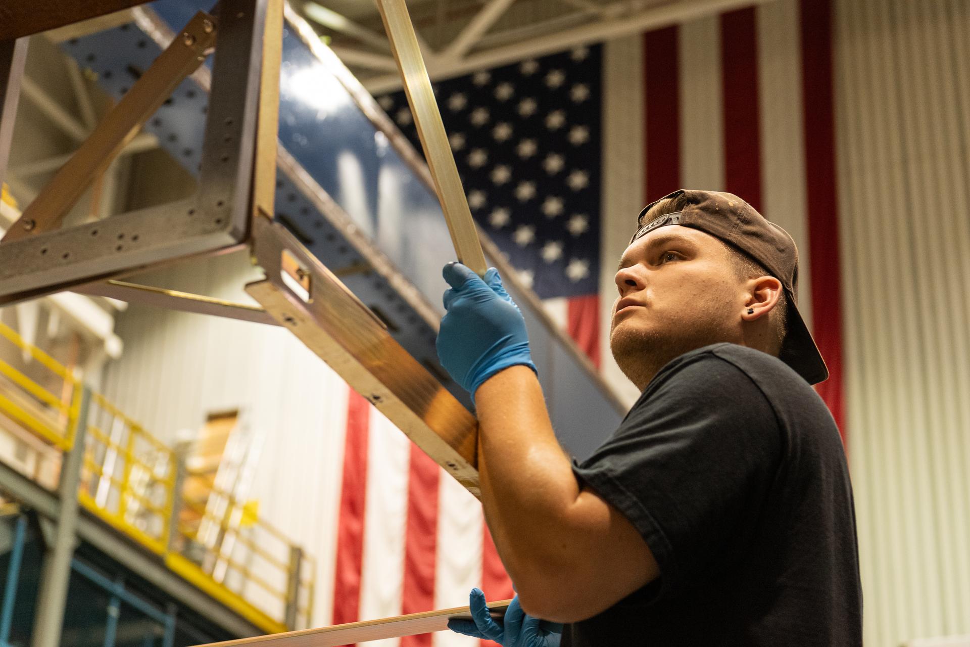
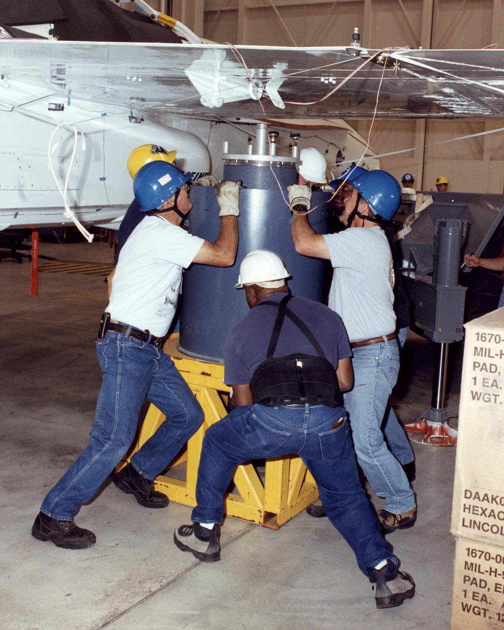
Boeing technicians that installed sensors inside of the Intertank STA.
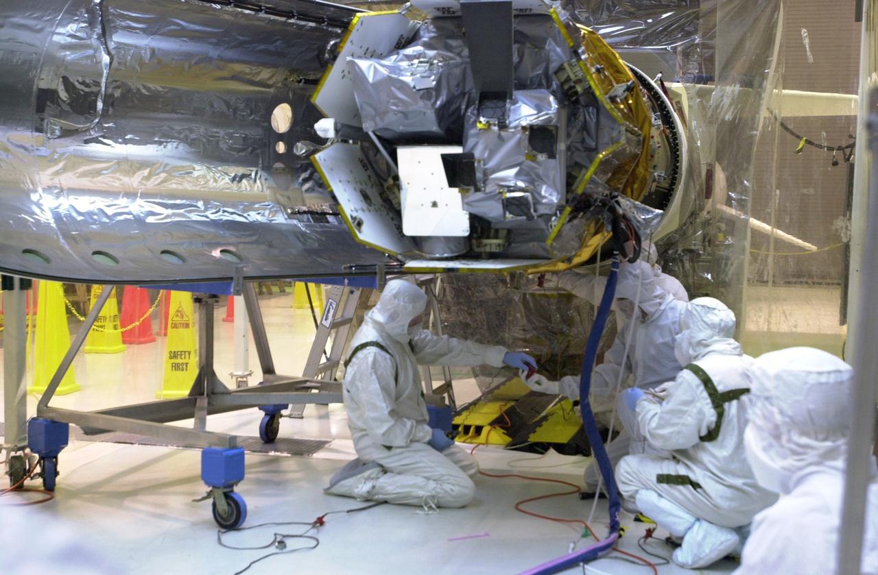
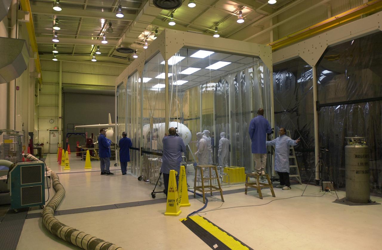
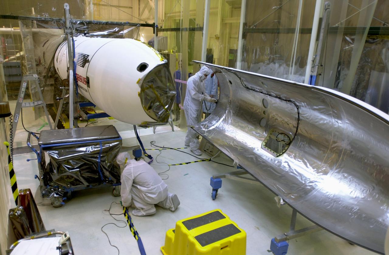
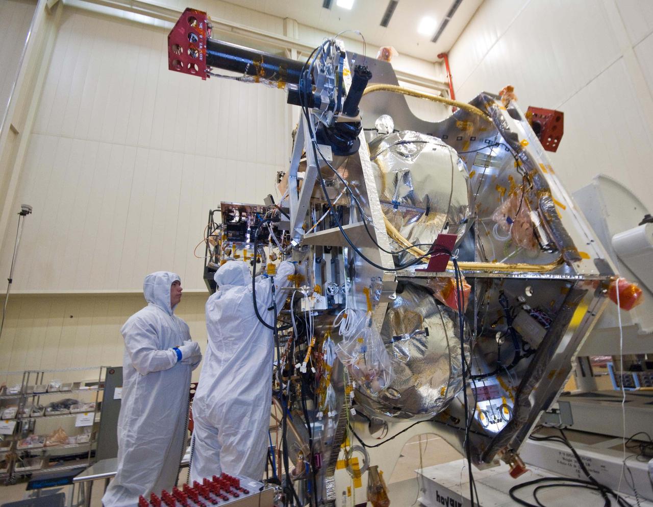
Technicians prepare the AIM spacecraft for fairing installation
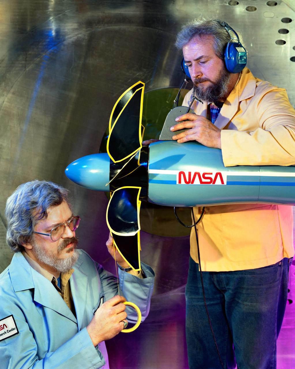
Technicians ready a single rotating propeller model in the 8x6 Supersonic Wind Tunnel
Seth Aulton, a mechanical engineering and integration technician, installs part of the Propellant Transfer System onto the servicing payload of OSAM-1 inside a cleanroom at Goddard Space Flight Center, Greenbelt, Md., Feb 14, 2023. This photo has been reviewed by OSAM-1 project management and the Export Control Office and is released for public view. NASA/Mike Guinto
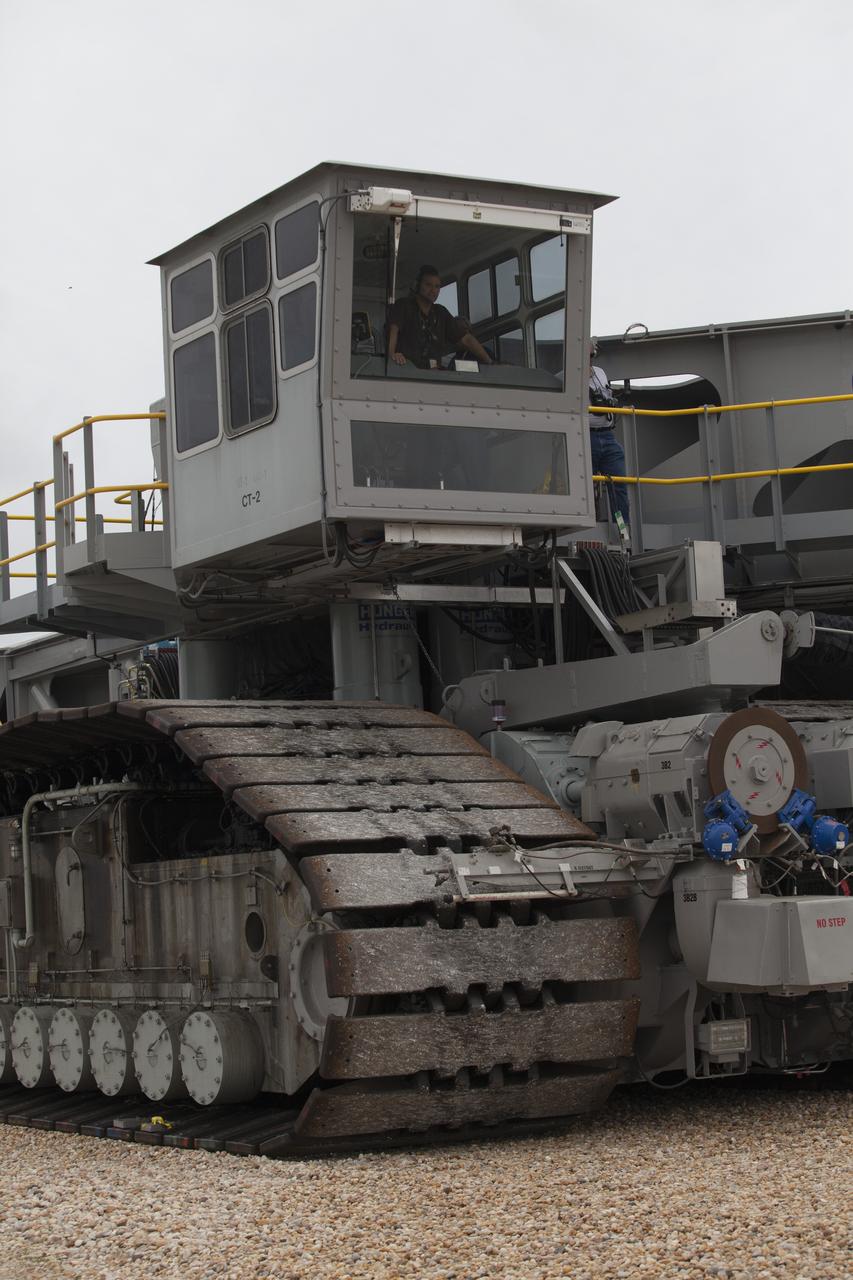
NASA’s upgraded crawler-transporter 2 (CT-2) returns to the Vehicle Assembly Building (VAB) from its trek to Launch Pad 39B at the agency’s Kennedy Space Center in Florida. CT-2 was driven along the crawlerway and onto Pad 39B to test recently completed upgrades and modifications for NASA’s journey to Mars. The Ground Systems Development and Operations Program at Kennedy oversaw upgrades to the crawler in the VAB. The crawler will carry the mobile launcher with Orion atop the Space Launch System rocket to Pad 39B for Exploration Mission 1.
Technicians are removed from SLS Intertank Test Article, ITA, after attaching to crosshead of load test Annex, Bldg. 4619,
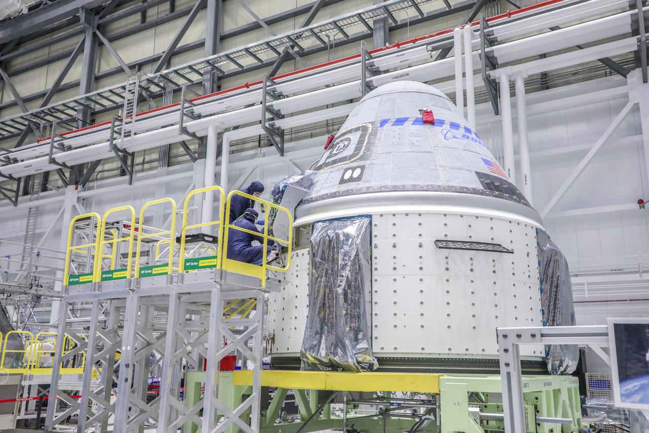
Starliner technicians work on the Orbital Flight Test-2 spacecraft in the high bay of Boeing’s Commercial Crew and Cargo Processing Facility at NASA’s Kennedy Space Center in Florida on Jan. 13, 2022.
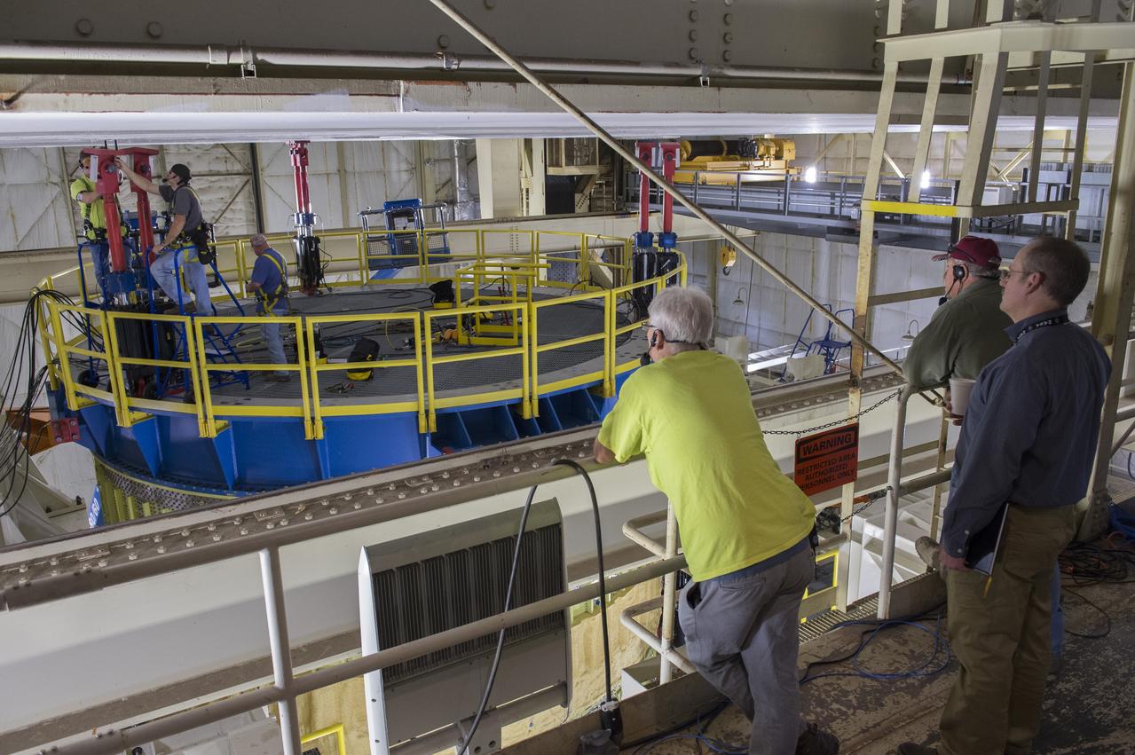
Robert Bobo, standing extreme right, and technicians view as SLS Intertank Test Article, ITA, is attached to crosshead of load test Annex, Bldg. 4619
Mechanical engineering and integration technician Ivan Pratt installs brackets onto the static load testing platform in preparation of an OSAM-1 ground support equipment proof test at Goddard Space Flight Center, Greenbelt Md., July 19, 2023. This photo has been reviewed by OSAM1 project management and the Export Control Office and is released for public view. NASA/Mike Guinto
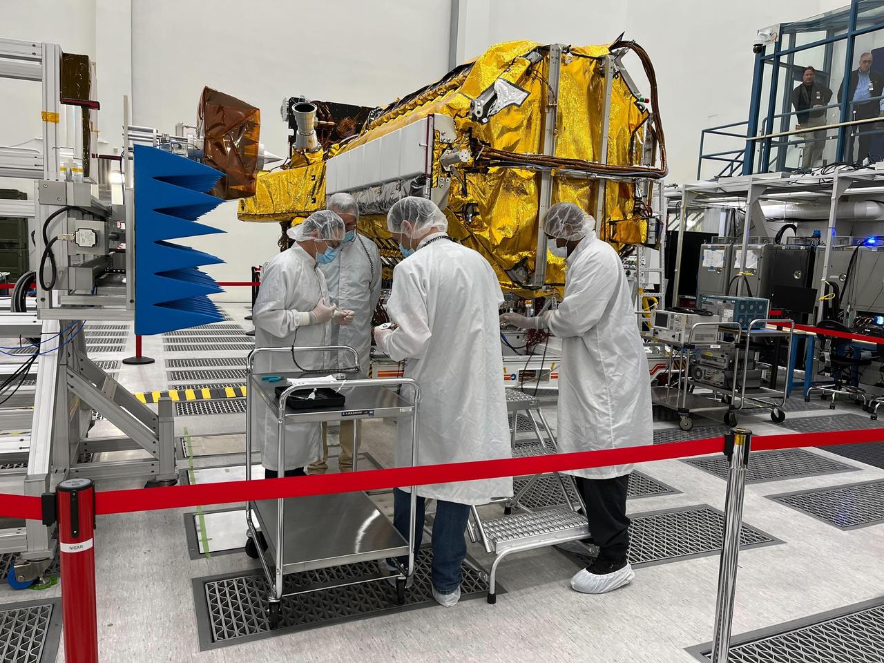
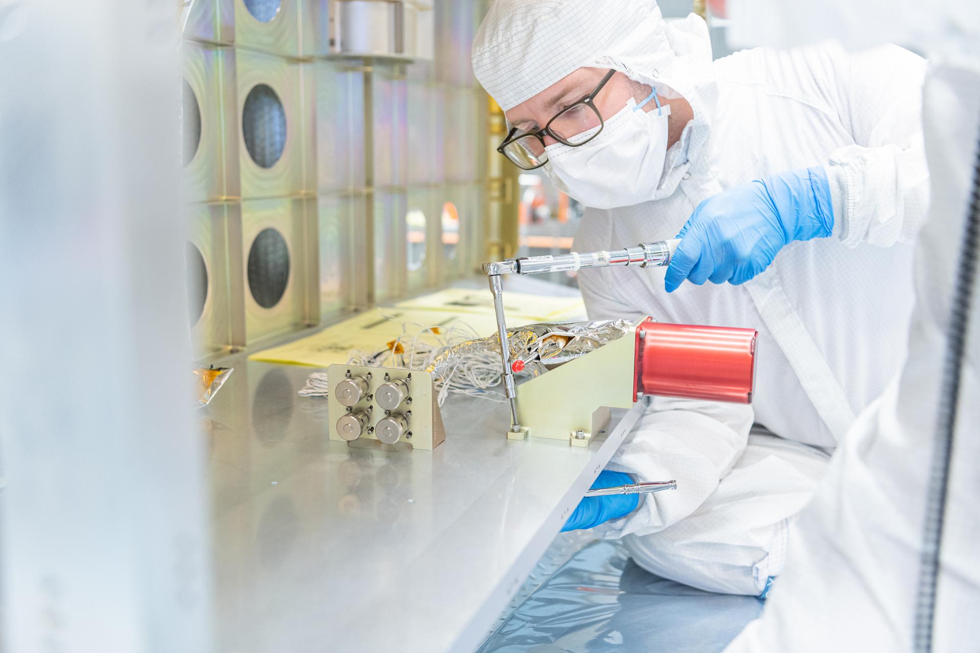
Engineers and technicians from NASA's Jet Propulsion Laboratory work on the NASA-ISRO Synthetic Aperture Radar (NISAR) science instrument payload in a clean room at JPL on Feb. 3, 2023. The payload is scheduled to ship to India in March 2023. The NISAR mission – a joint effort between NASA and ISRO – will measure changes to Earth's land ice surfaces down to fractions of an inch. Data collected by this satellite will help researchers monitor a wide range of changes critical to life on Earth in unprecedented detail. This includes spotting warning signs of imminent volcanic eruptions, helping to monitor groundwater supplies, tracking the melt rate of ice sheets tied to sea level rise, and observing shifts in the distribution of vegetation around the world. The data will inform humanity's responses to urgent challenges posed by natural disasters and climate change, and help communities prepare for and manage hazards. There are two instruments on the satellite that will send and receive radar signals to and from Earth's surface to make the mission's measurements. An L-band synthetic aperture radar (SAR), which uses a signal wavelength of around 9 inches (24 centimeters), and an S-band SAR with a signal wavelength of nearly 5 inches (12 centimeters). Both will bounce their microwave signal off of the planet's surface and record how long it takes the signal to make one roundtrip, as well as the strength of that return signal. This enables the researchers to calculate the distance from the spacecraft to Earth's surface and thereby determine how the land or ice is changing. An antenna reflector nearly 40 feet (12 meters) in diameter, supported by a deployable boom, will focus the microwave signals sent and received by the SARs. JPL, which is managed for NASA by Caltech in Pasadena, leads the U.S. component of NISAR and is providing the mission's L-band SAR instrument. NASA is also providing the radar reflector antenna, the deployable boom, a high-rate communication subsystem for science data, GPS receivers, a solid-state recorder, and payload data subsystem. ISRO is providing the spacecraft bus, the S-band SAR, the launch vehicle, and associated launch services and satellite mission operations. https://photojournal.jpl.nasa.gov/catalog/PIA25771
Mechanical engineering and integration technician, Lucas Keim, holds up a piece of ground support equipment during a proof test at Goddard Space Flight Center, Greenbelt Md., June 22, 2023. This photo has been reviewed by OSAM1 project management and the Export Control Office and is released for public view. NASA/Mike Guinto
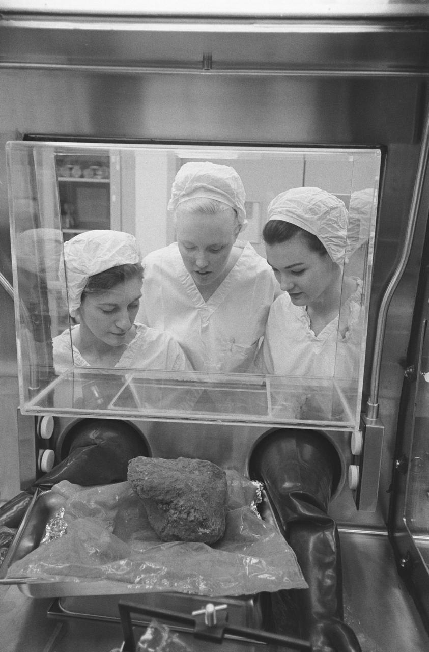
S71-21244 (24 Feb. 1971) --- Three Brown and Root/Northrop technicians in the Nonsterile Nitrogen Laboratory in the Lunar Receiving Laboratory (LRL) peer through glass at the much-discussed basketball size rock which Apollo 14 crewmen brought back from the Fra Mauro area of the moon. They are, left to right, Linda Tyler, Nancy L. Trent and Sandra Richards.
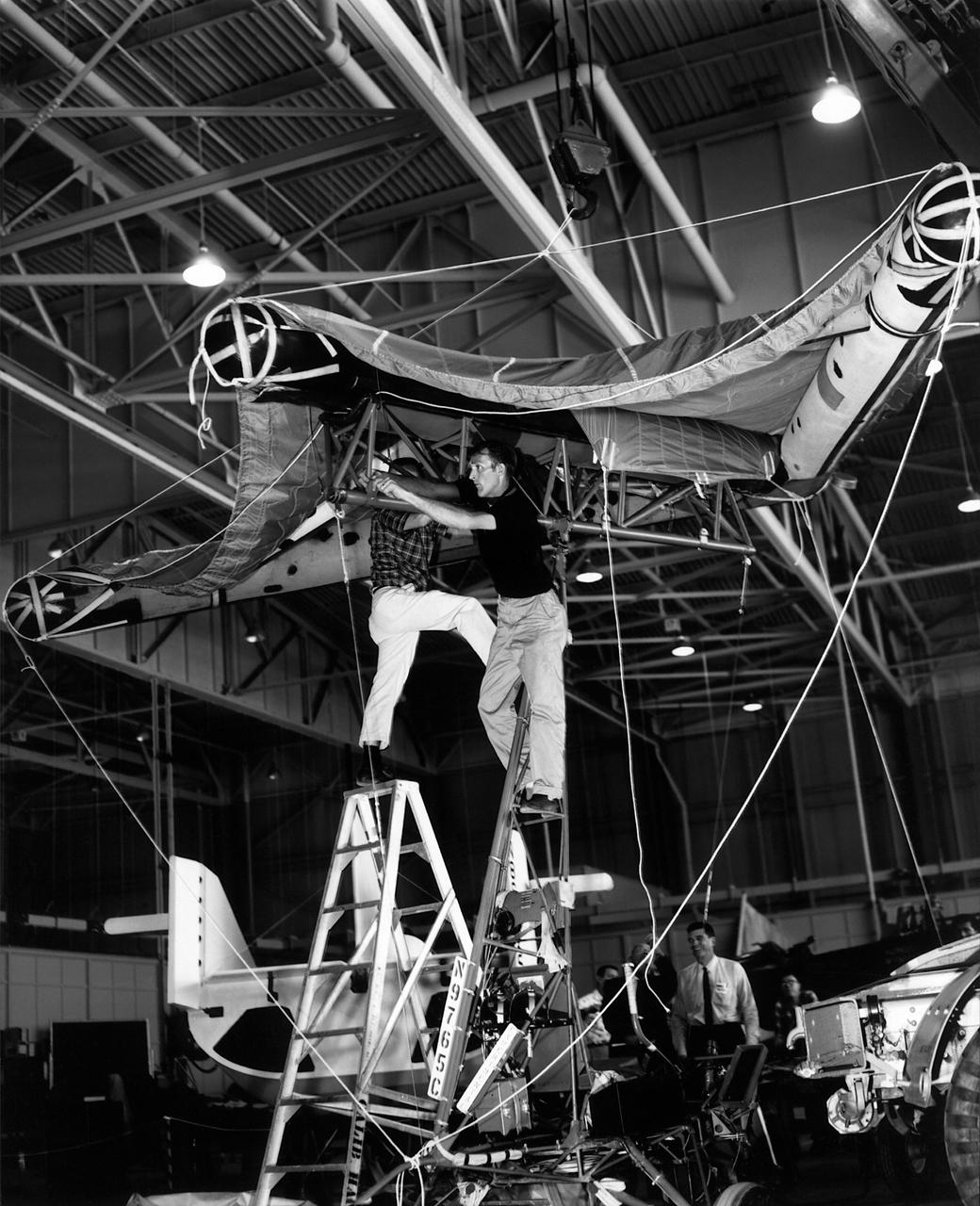
This photo shows the Paresev (Paraglider Research Vehicle) space frame receiving a new wing. Frank Fedor and a technician helper are attaching a half-scale version of an inflatable wing in a hangar at NASA Flight Research Center at Edwards, California. The Paresev in this configuration was called the 1-C and was expected to closely approximate the aerodynamic characteristics that would be encountered with the Gemini space capsule with a parawing extended. The whole wing was not inflatable; the three chambers that acted as spars and supported the wing inflated.
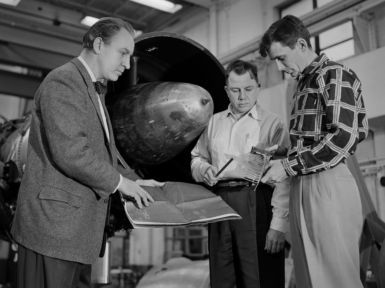
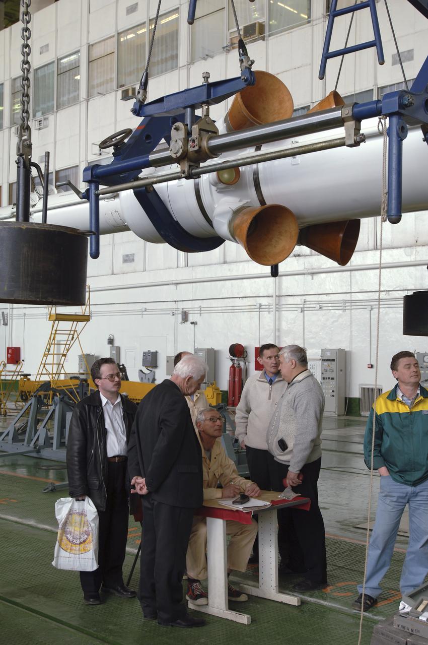
Researcher Bill Reiwaldt discusses the preparations for a test in the Altitude Wind Tunnel with technicians Jack Wagner and Dick Golladay at the National Advisory Committee for Aeronautics (NACA) Lewis Flight Propulsion Laboratory. Research engineers developed ideas for tests that were often in response to requests from the military or aircraft industry. Arrangements were made to obtain an engine for the study and to transport it to the Cleveland laboratory. The engine was brought into the facility’s shop area, where it was readied for investigation. It was common for several different engines to be worked on simultaneously in the shop. The researcher would discuss the engine and the test objectives with the Test Installation Division and the facility’s technicians. The operations team would handle the installation of the instrumentation and fitting the test into the facility’s schedule. Upon completion of the previous test, the engine was removed. The next engine was lifted by an overhead crane and transported from the shop to the test section. The engine was connected to the measurement devices and fuel and oil supply lines. Engines were tested over numerous runs under varying conditions and with variations on the configuration. The findings and test procedure were then described in research or technical memorandums and distributed to industry.
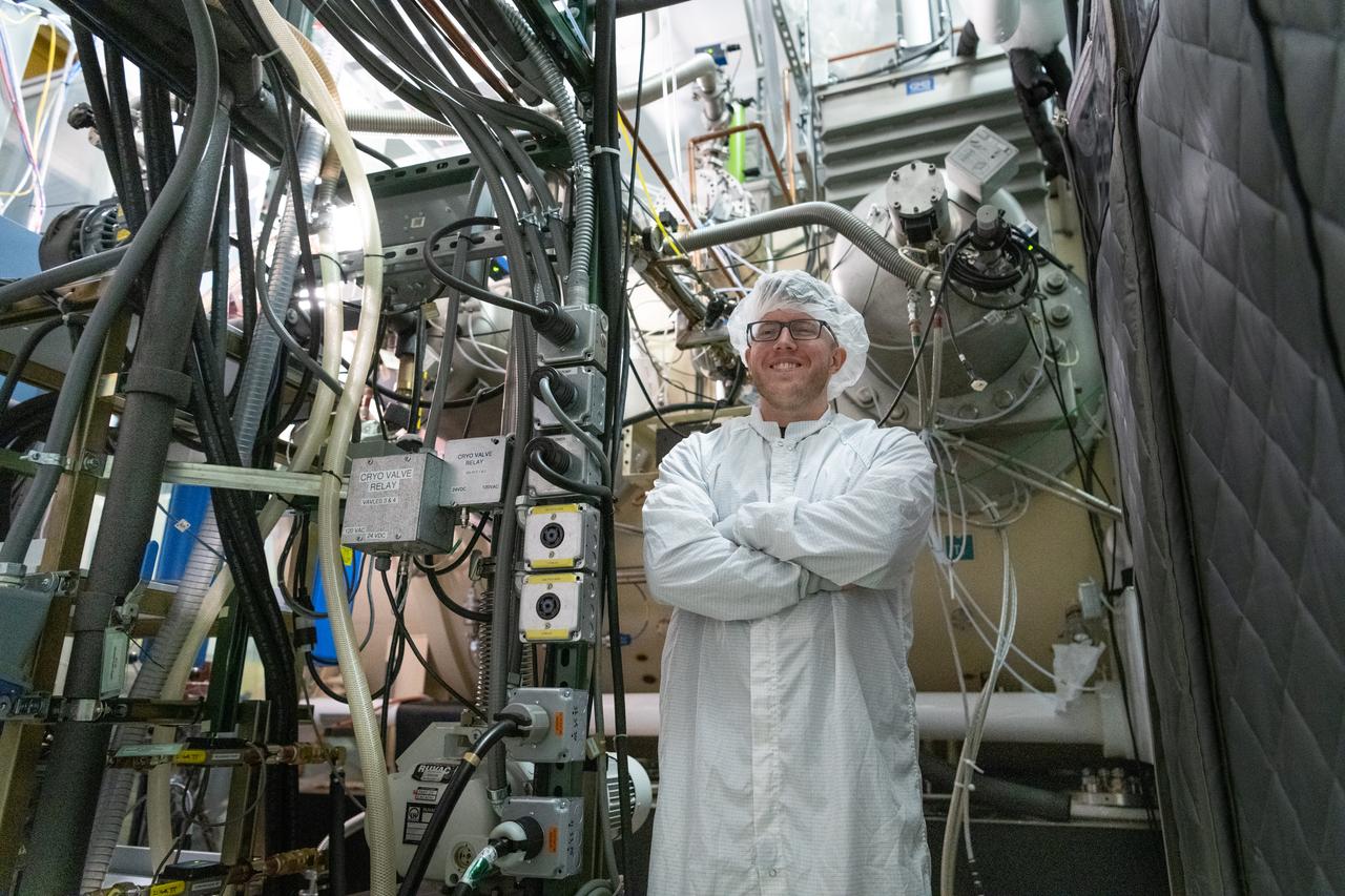
Thermal vacuum technician, Sean Cook, monitors the Ocean Color Instrument (OCI) thermal vacuum chamber temperatures during the environmental test campaign. OCI is a highly advanced optical spectrometer that will be used to measure properties of light over portions of the electromagnetic spectrum. It will enable continuous measurement of light at finer wavelength resolution than previous NASA satellite sensors, extending key system ocean color data records for climate studies. OCI is PACE's (Plankton, Aerosol, Cloud, ocean Ecosystem) primary sensor built at Goddard Space Flight Center in Greenbelt, MD.
NASA Dryden technicians (Dave Dennis, Freddy Green and Jeff Doughty) position a support cylinder under the right wing of the Active Aeroelastic Wing F/A-18 test aircraft prior to ground vibration tests.
Mechanical engineering and integration technician Seth Alton crane lifts the OSAM-1 power supply unit into the thermal vacuum chamber at Goddard Space Flight Center, Greenbelt Md., April 12, 2023. This photo has been reviewed by OSAM1 project management and the Export Control Office and is released for public view. NASA/Mike Guinto
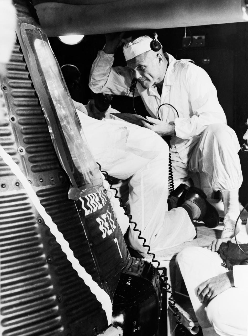
S61-03740 (20 July 1961) --- Astronaut John H. Glenn Jr. and a technician examine the interior of the Liberty Bell 7, the capsule flown a few days later during the Mercury-Redstone 4 mission with astronaut Virgil I. (Gus) Grissom. Photo credit: NASA
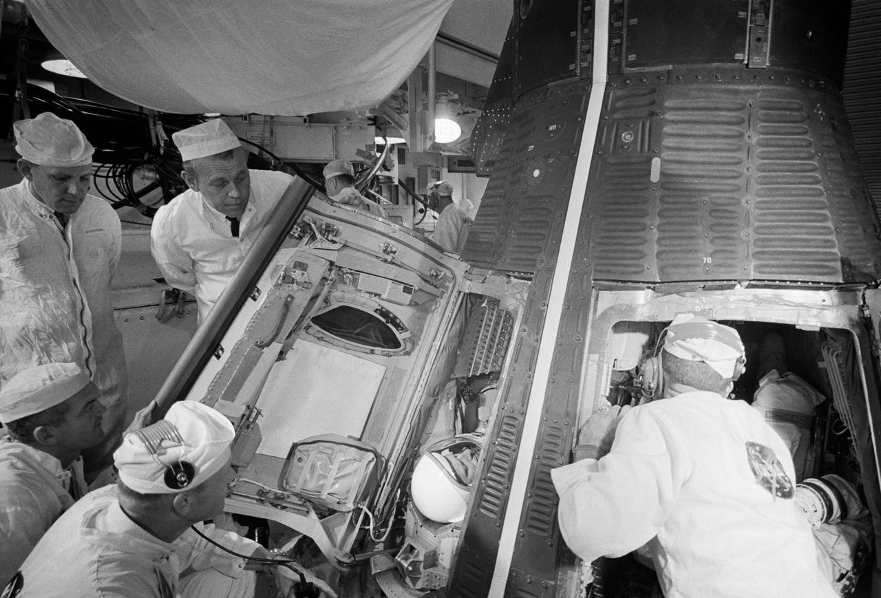
S66-56177 (10 Sept. 1966) --- Technicians in the White Room atop Pad 19 prepare to close hatches on the Gemini-11 spacecraft during prelaunch countdown. Inside the spacecraft are astronauts Charles Conrad Jr., command pilot, and Richard F. Gordon Jr., pilot. Photo credit: NASA
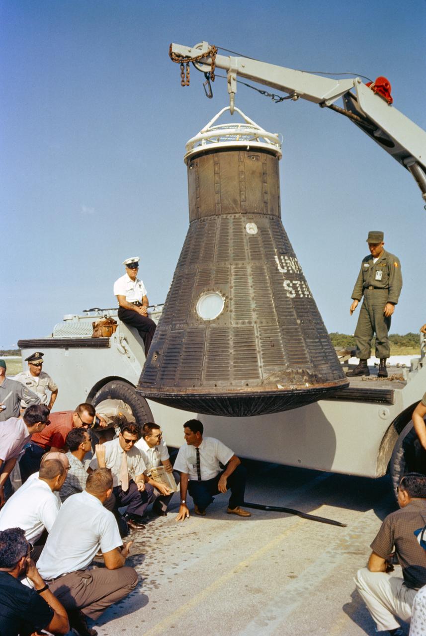
S64-14861 (1962) --- Department of Defense (DOD) recovery personnel and spacecraft technicians from NASA and McDonnell Aircraft Corp., inspect astronaut John Glenn's Mercury spacecraft, Friendship 7, following its return to Cape Canaveral after recovery in the Atlantic Ocean. Photo credit: NASA
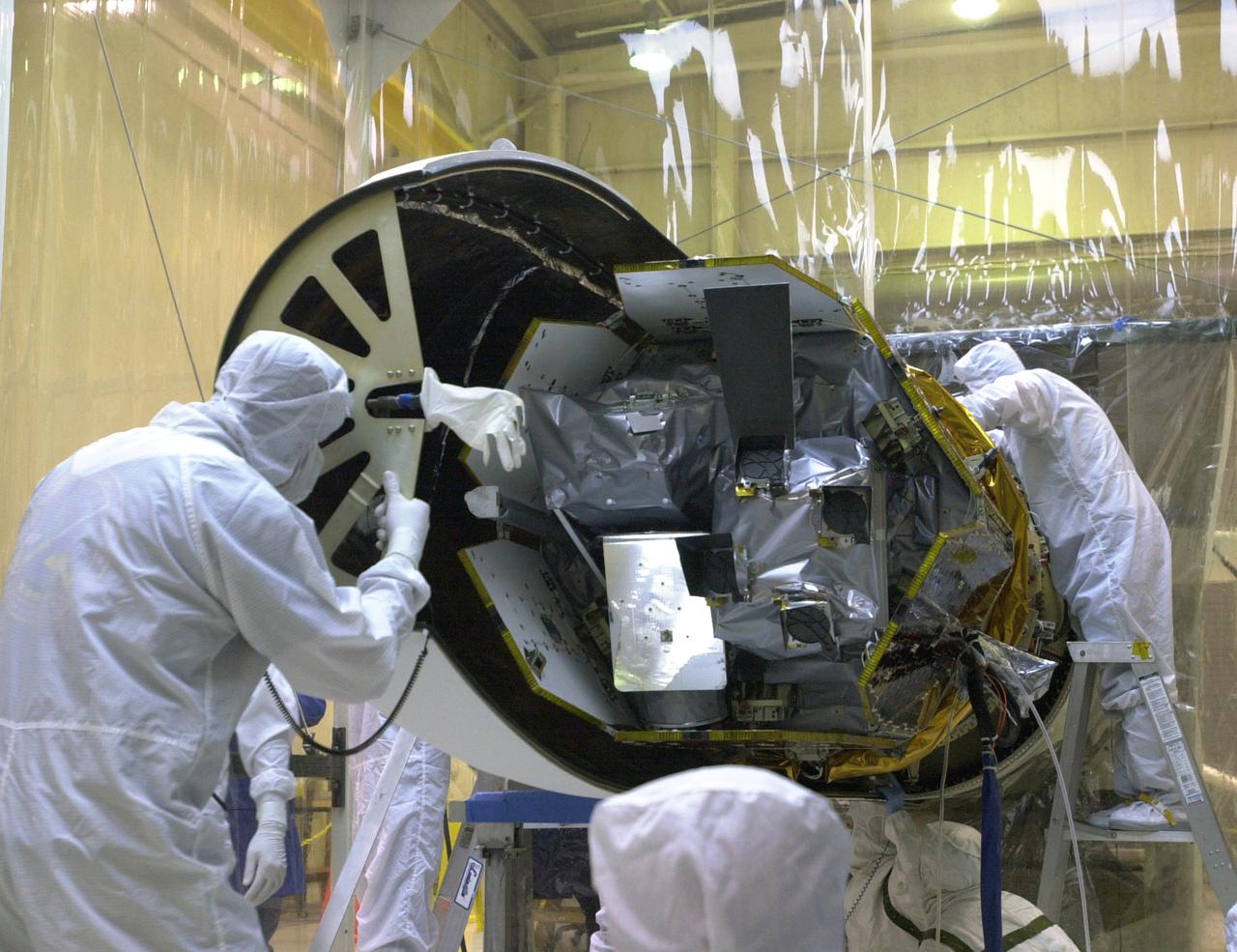
At Vandenberg Air Force Base in California, technicians prepare the AIM spacecraft for fairing installation. The fairing is a molded structure that fits around the spacecraft and forms an aerodynamically smooth nose cone, protecting the spacecraft during launch. Launch will be from a Pegasus XL rocket, carried and released by Orbital Sciences L-1011 jet aircraft. AIM, which stands for Aeronomy of Ice in the Mesosphere, is being prepared for integrated testing and a flight simulation. The AIM spacecraft will fly three instruments designed to study polar mesospheric clouds located at the edge of space, 50 miles above the Earth's surface in the coldest part of the planet's atmosphere. The mission's primary goal is to explain why these clouds form and what has caused them to become brighter and more numerous and appear at lower latitudes in recent years. AIM's results will provide the basis for the study of long-term variability in the mesospheric climate and its relationship to global climate change. Launch is scheduled for April 25.
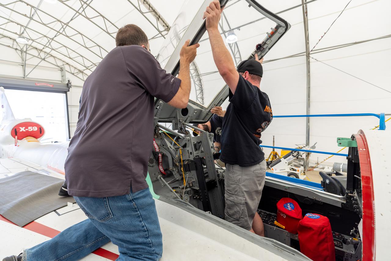
Lockheed Martin technicians temporarily remove the canopy from the X-59 in preparation for final installation of the ejection seat into the aircraft.
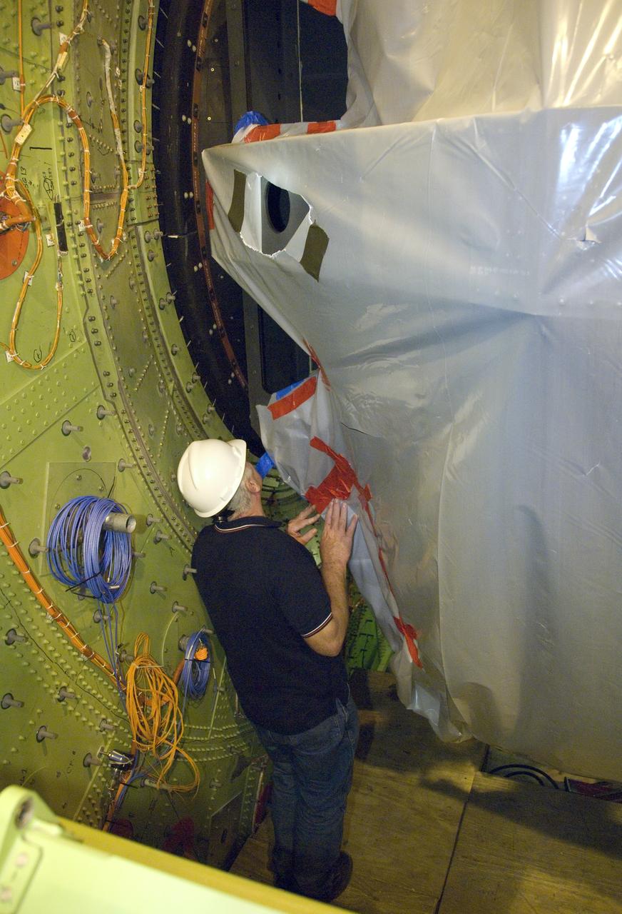
Technicians carefully disassemble portions of the aperture mounting assembly from NASA's SOFIA aircraft in preparation for removal of the telescope.
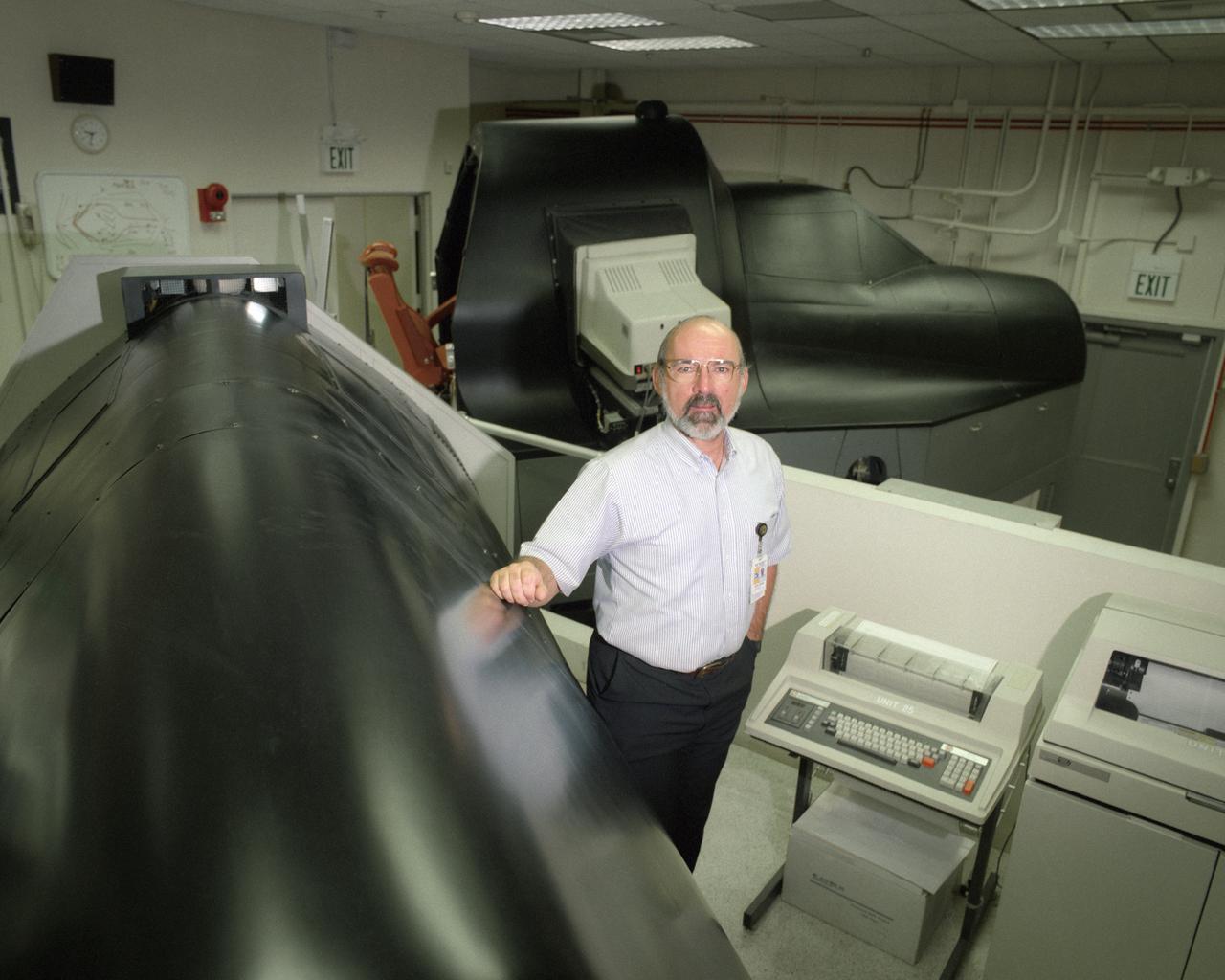
Electronics technician Joe Ciganek was responsible for operation and maintenance of the SR-71 simulator while it was at NASA's Dryden Flight Research Center.
A technician guides SOFIA's primary mirror assembly into the aircraft's telescope cavity completing the mirror reinstallation following its initial coating.
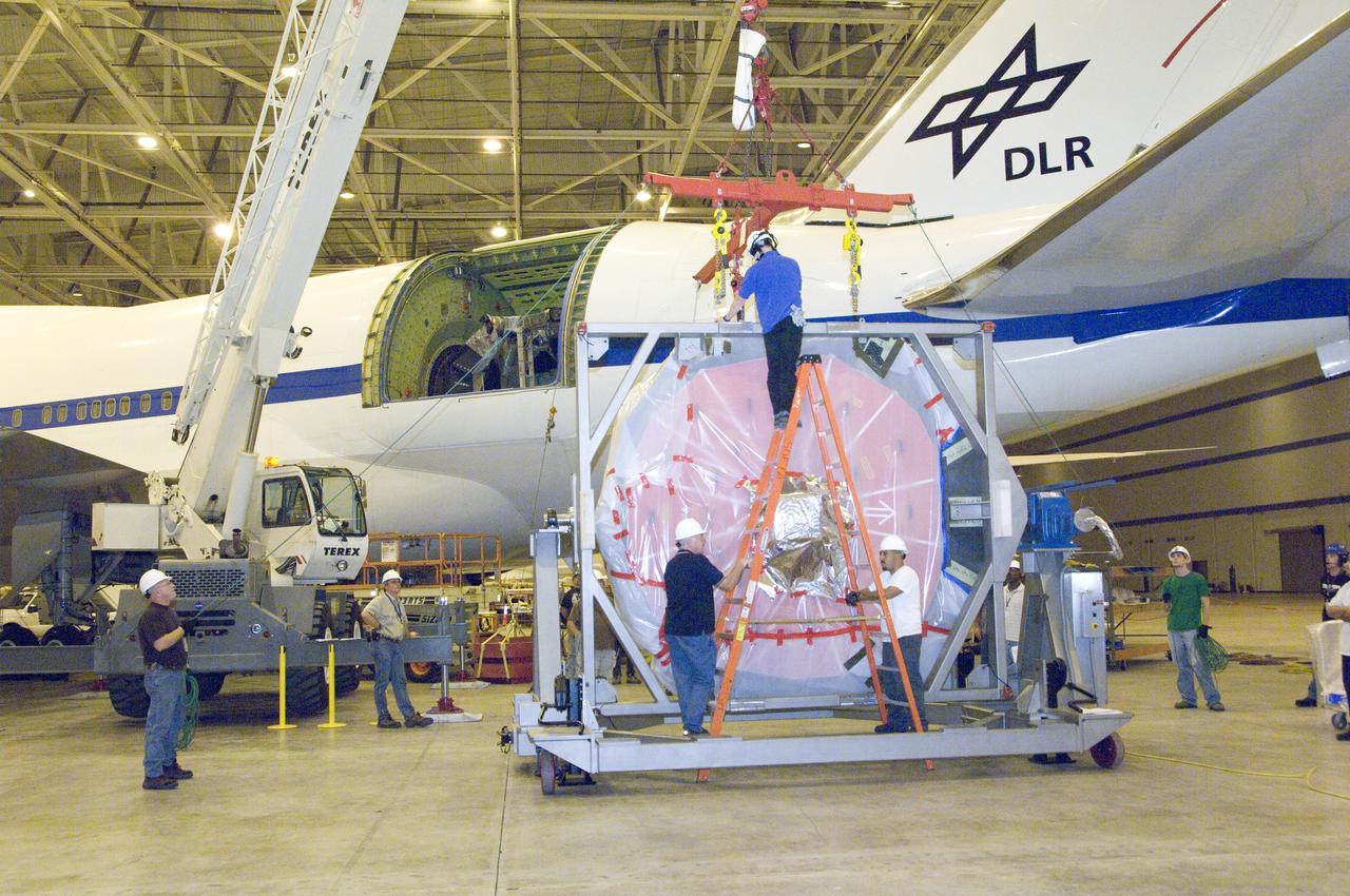
Engineers and technicians prepare SOFIA's German-built primary mirror assembly for reinstallation into NASA's 747SP airborne observatory.
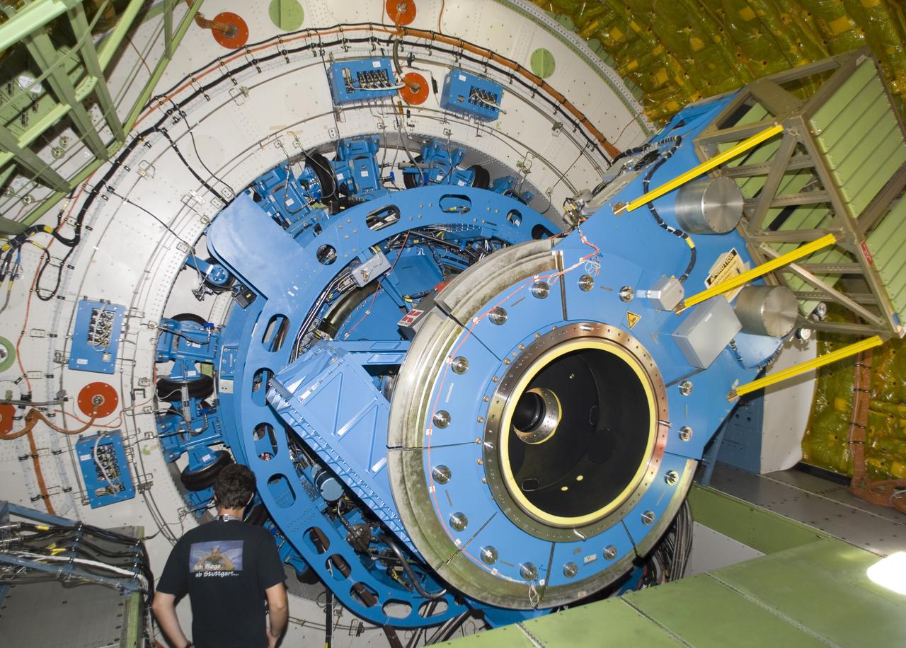
A technician examines the instrument mounting structure and bulkhead of the German-built infrared telescope installed in NASA's SOFIA airborne observatory.
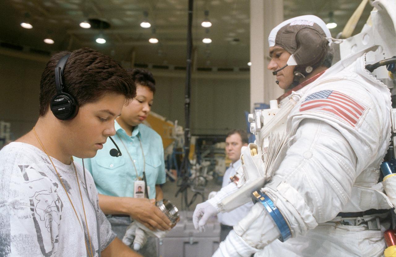
S92-42681 (28 July 1992) --- STS-53 Discovery, Orbiter Vehicle (OV) 103, Mission Specialist (MS) Michael R.U. Clifford, wearing extravehicular mobility unit (EMU) and communications carrier assembly (CCA), dons gloves with assistance from two technicians. Clifford is preparing for an underwater contingency extravehicular activity (EVA) simulation in JSC's Weightless Environment Training Facility (WETF) Bldg 29 pool.
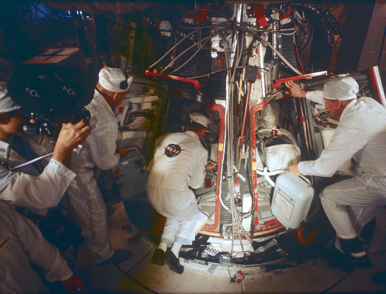
S65-61835 (15 Nov. 1965) --- Technicians assist the prime crew for the Gemini-7 spaceflight in systems checks inside their spacecraft in the White Room atop Pad 19. Prime crew members are astronauts Frank Borman (left, inside spacecraft), command pilot, and James A. Lovell Jr. (right, inside spacecraft), pilot. They wear the new light-weight spacesuit planned for use during their 14-day mission. Photo credit: NASA
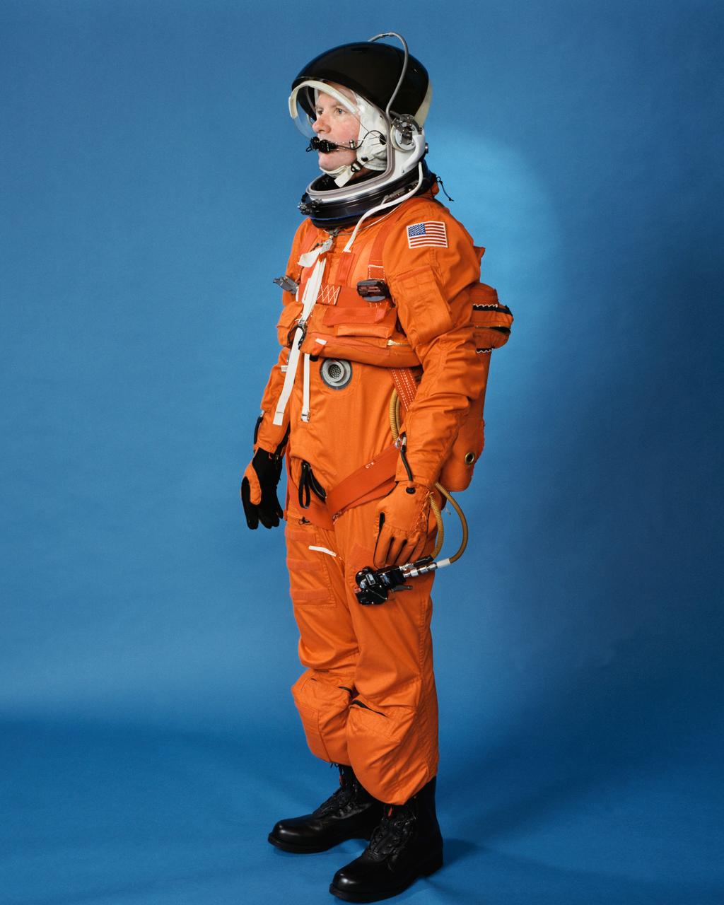
Space shuttle orange launch and entry suit (LES), a partial pressure suit, is modeled by a technician. LES was designed for STS-26, the return to flight mission, and subsequent missions. Included in the crew escape system (CES) package are launch and entry helmet (LEH) with communications carrier (COMM CAP), parachute pack and harness, life raft, life preserver unit (LPU), LES gloves, suit oxygen manifold and valves, boots, and survival gear.
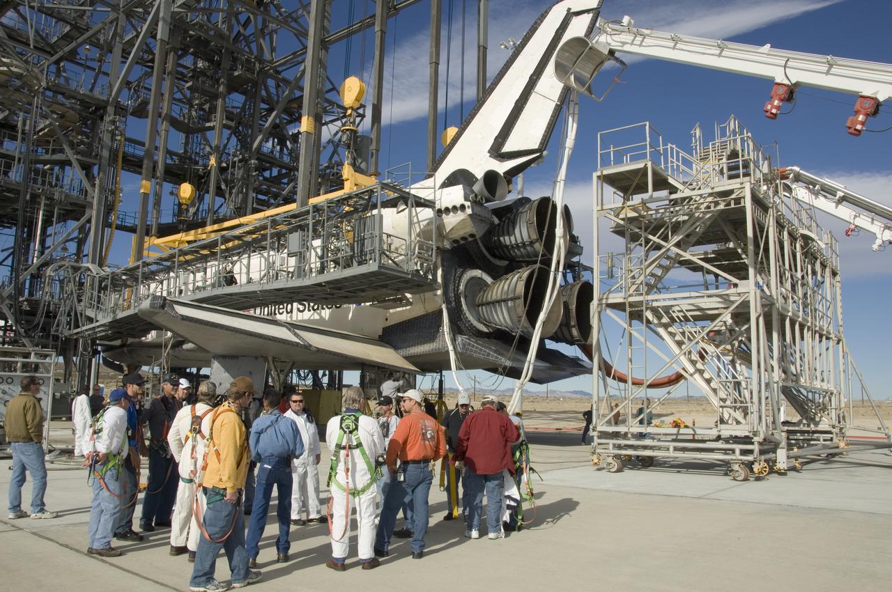
United Space Alliance technicians gather around the rear of Space Shuttle Endeavour for a safety briefing prior to moving the tail workstand around the shuttle's engines.

Technicians check out the mounting structure of the 20-metric-ton infrared telescope installed in NASA's Stratospheric Observatory for Infrared Astronomy (SOFIA).
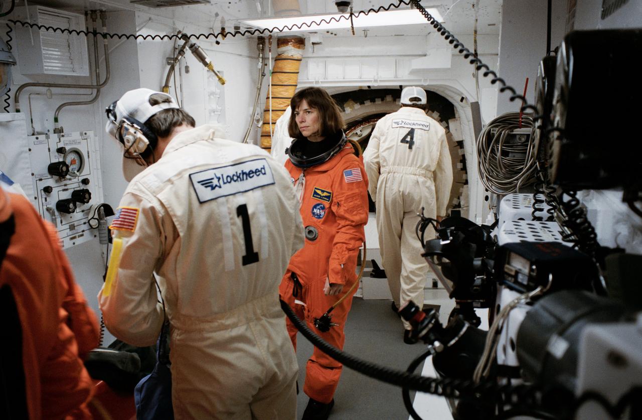
STS-32 Mission Specialist (MS) Bonnie J. Dunbar, wearing launch and entry suit (LES), looks on as technicians prepare LES equipment in the white room on the orbiter access arm at Kennedy Space Center (KSC) Launch Complex (LC) Pad 39A before entering Columbia, Orbiter Vehicle (OV) 102. In the background, a technician looks through OV-102 side hatch.
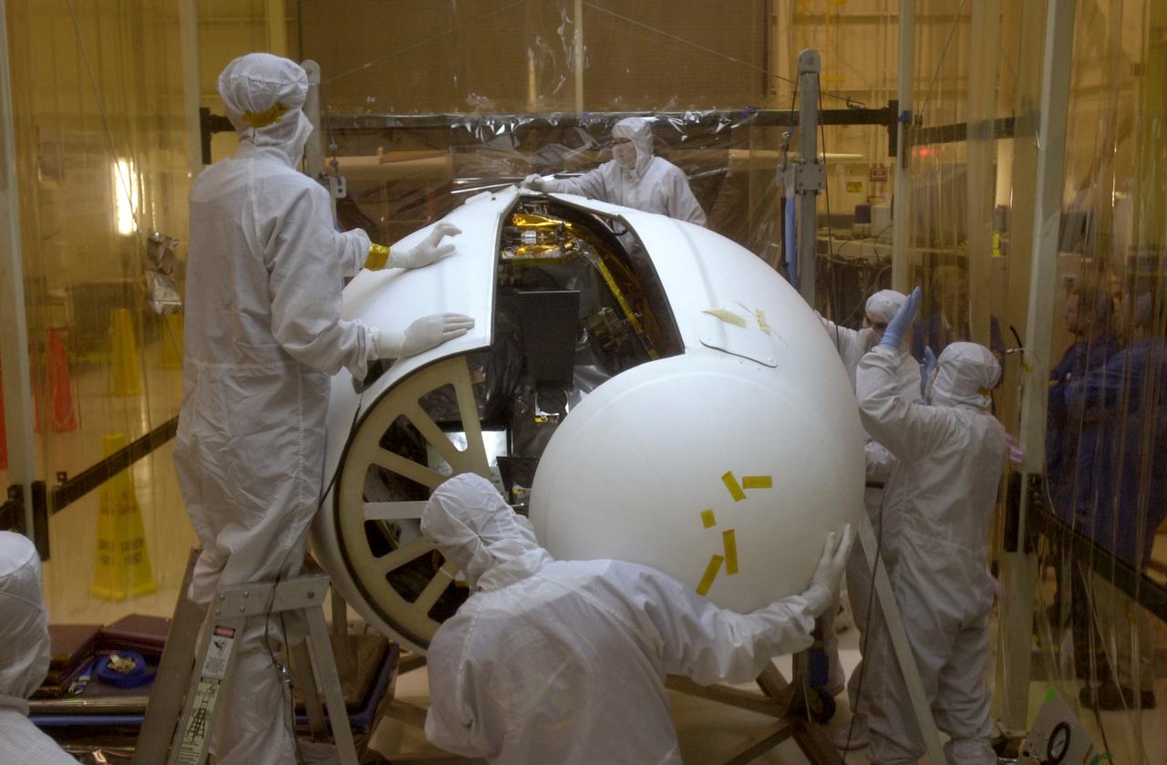
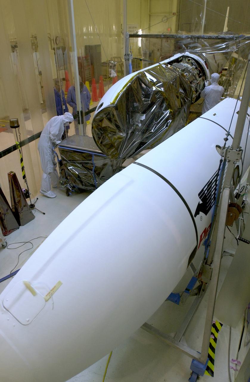
At Vandenberg Air Force Base in California, under the protective clean tent, technicians move the second half of the fairing into place around the AIM spacecraft. The fairing is a molded structure that fits around the spacecraft and forms an aerodynamically smooth nose cone, protecting the spacecraft during launch. Launch will be from a Pegasus XL rocket, carried and released by Orbital Sciences L-1011 jet aircraft. AIM, which stands for Aeronomy of Ice in the Mesosphere, is being prepared for integrated testing and a flight simulation. The AIM spacecraft will fly three instruments designed to study polar mesospheric clouds located at the edge of space, 50 miles above the Earth's surface in the coldest part of the planet's atmosphere. The mission's primary goal is to explain why these clouds form and what has caused them to become brighter and more numerous and appear at lower latitudes in recent years. AIM's results will provide the basis for the study of long-term variability in the mesospheric climate and its relationship to global climate change. Launch is scheduled for April 25.
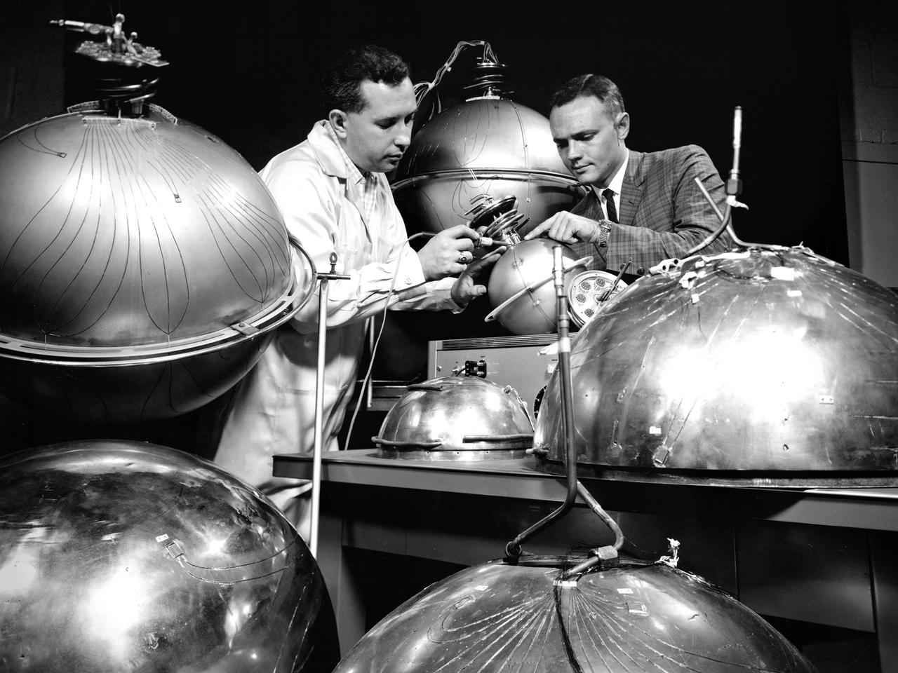
An engineer and technician at the National Aeronautics and Space Administration (NASA) Lewis Research Center install the instrumentation on spherical fuel tanks for an investigation of the behavior of liquids in microgravity. Lewis researchers were undertaking a broad effort to study the heat transfer properties of high energy propellants such as liquid hydrogen in microgravity. In the center’s 2.2-Second Drop Tower they investigated the wetting characteristics of liquid and the liquid-vapor configurations, and predicted the equilibrium state in microgravity conditions. Lewis was also conducting a series microgravity investigations which launched 9-inch diameter spherical dewars, seen here, on an Aerobee sounding rocket. A camera inside the rocket filmed the liquid hydrogen’s behavior during its 4 to 7 minutes of freefall. The researchers concluded, however, that they needed to extend the weightlessness period to obtain better results. So they designed an experiment to be launched on an Atlas missile that would provide 21 minutes of weightlessness. The experiment was flight qualified at Lewis. The 36-percent full liquid hydrogen stainless steel dewar was launched on the Atlas on February 25, 1964. The instrumentation measured temperature, pressure, vacuum, and liquid level. Temperature instrumentation indicated wall drying during the freefall. The resultant pressure-rise characteristics were similar to those used for the normal-gravity test.
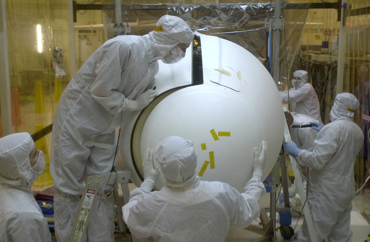
At Vandenberg Air Force Base in California, under the protective clean tent, technicians examine the installation of the fairing around the AIM spacecraft. The fairing is a molded structure that fits around the spacecraft and forms an aerodynamically smooth nose cone, protecting the spacecraft during launch. Launch will be from a Pegasus XL rocket, carried and released by Orbital Sciences L-1011 jet aircraft. AIM, which stands for Aeronomy of Ice in the Mesosphere, is being prepared for integrated testing and a flight simulation. The AIM spacecraft will fly three instruments designed to study polar mesospheric clouds located at the edge of space, 50 miles above the Earth's surface in the coldest part of the planet's atmosphere. The mission's primary goal is to explain why these clouds form and what has caused them to become brighter and more numerous and appear at lower latitudes in recent years. AIM's results will provide the basis for the study of long-term variability in the mesospheric climate and its relationship to global climate change. Launch is scheduled for April 25.
At Vandenberg Air Force Base in California, under the protective clean tent, technicians work on the second half of the fairing to be installed around the AIM spacecraft. The fairing is a molded structure that fits around the spacecraft and forms an aerodynamically smooth nose cone, protecting the spacecraft during launch. Launch will be from a Pegasus XL rocket, carried and released by Orbital Sciences L-1011 jet aircraft. AIM, which stands for Aeronomy of Ice in the Mesosphere, is being prepared for integrated testing and a flight simulation. The AIM spacecraft will fly three instruments designed to study polar mesospheric clouds located at the edge of space, 50 miles above the Earth's surface in the coldest part of the planet's atmosphere. The mission's primary goal is to explain why these clouds form and what has caused them to become brighter and more numerous and appear at lower latitudes in recent years. AIM's results will provide the basis for the study of long-term variability in the mesospheric climate and its relationship to global climate change. Launch is scheduled for April 25.
At Vandenberg Air Force Base in California, under the protective clean tent, technicians begin installing the fairing around the AIM spacecraft. The fairing is a molded structure that fits around the spacecraft and forms an aerodynamically smooth nose cone, protecting the spacecraft during launch. Launch will be from a Pegasus XL rocket, carried and released by Orbital Sciences L-1011 jet aircraft. AIM, which stands for Aeronomy of Ice in the Mesosphere, is being prepared for integrated testing and a flight simulation. The AIM spacecraft will fly three instruments designed to study polar mesospheric clouds located at the edge of space, 50 miles above the Earth's surface in the coldest part of the planet's atmosphere. The mission's primary goal is to explain why these clouds form and what has caused them to become brighter and more numerous and appear at lower latitudes in recent years. AIM's results will provide the basis for the study of long-term variability in the mesospheric climate and its relationship to global climate change. Launch is scheduled for April 25.
At Vandenberg Air Force Base in California, under the protective clean tent, technicians maneuver the second half of the fairing into place around the AIM spacecraft. The fairing is a molded structure that fits around the spacecraft and forms an aerodynamically smooth nose cone, protecting the spacecraft during launch. Launch will be from a Pegasus XL rocket, carried and released by Orbital Sciences L-1011 jet aircraft. AIM, which stands for Aeronomy of Ice in the Mesosphere, is being prepared for integrated testing and a flight simulation. The AIM spacecraft will fly three instruments designed to study polar mesospheric clouds located at the edge of space, 50 miles above the Earth's surface in the coldest part of the planet's atmosphere. The mission's primary goal is to explain why these clouds form and what has caused them to become brighter and more numerous and appear at lower latitudes in recent years. AIM's results will provide the basis for the study of long-term variability in the mesospheric climate and its relationship to global climate change. Launch is scheduled for April 25.
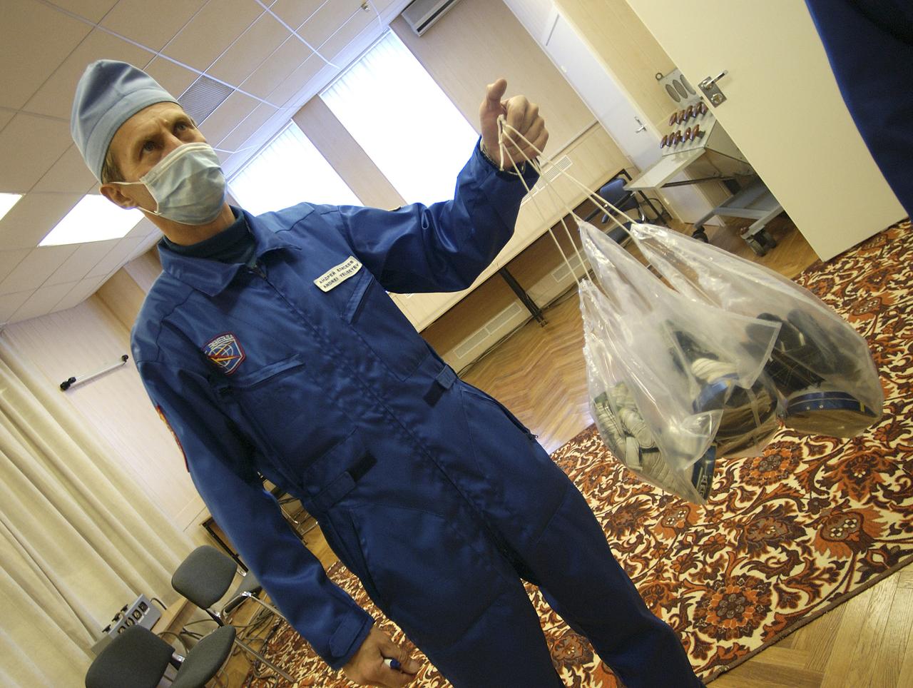
A Russian Suit Technician carries the gloves of all three Expedition 10 crew members Friday, October 5, 2004, at the Baikonur Cosmodrome in Kazakhstan. Expedition 10 Commander and NASA Science Officer Leroy Chiao, Russian Space Forces cosmonaut Yuri Shargin and Flight Engineer and Soyuz Commander Salizhan Sharipov will launch on October 14th to the International Space Station. Photo Credit: (NASA/Bill Ingalls)
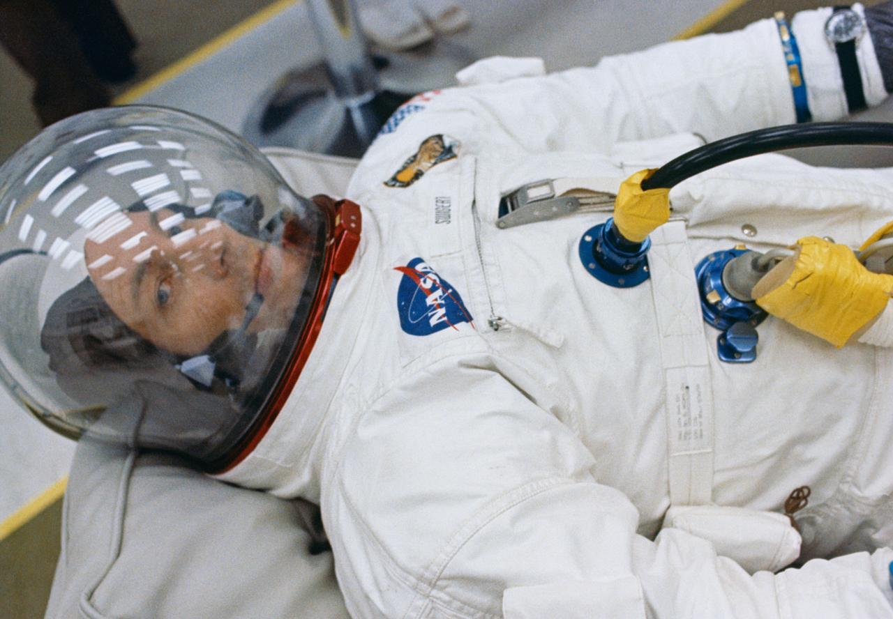
S70-34847 (11 April 1970) --- Astronaut John L. Swigert Jr., command module pilot for NASA?s third lunar landing mission, appears to be relaxing in the suiting room at Kennedy Space Center prior to launch. Other members of the Apollo 13 crew include astronauts James A. Lovell Jr., commander, and Fred W. Haise Jr., lunar module pilot. Swigert replaced astronaut Thomas K. Mattingly II when it was discovered that Mattingly had been exposed to the measles.
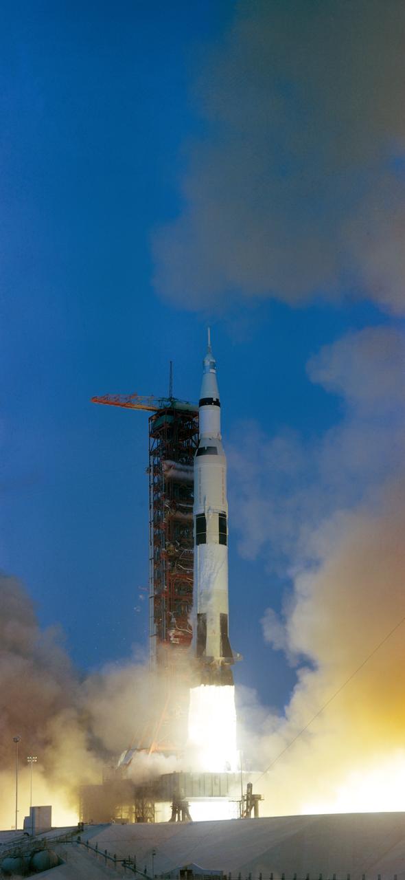
S70-34853 (11 April 1970) --- The Apollo 13 (Spacecraft 109/Lunar Module 7/Saturn 508) space vehicle is launched from Pad A, Launch Complex 39, Kennedy Space Center (KSC), at 2:13 p.m. (EST), April 11, 1970. The crew of the National Aeronautics and Space Administration's (NASA) third lunar landing mission are astronauts James A., Lovell Jr., commander; John L. Swigert Jr., command module pilot; and Fred W. Haise Jr., lunar module pilot.
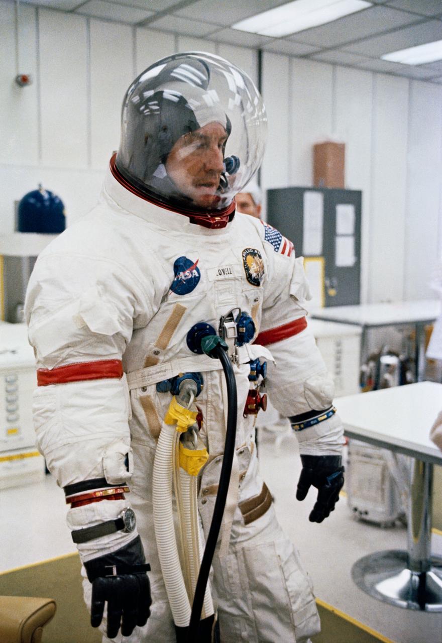
S70-34848 (11 April 1970) --- Astronaut James A. Lovell Jr., commander for NASA's Apollo 13 mission, undergoes space suit checks a few hours before launch. Other members of the crew are astronauts Fred W. Haise Jr., lunar module pilot, and John L. Swigert Jr., command module pilot. Swigert replaced astronaut Thomas K. Mattingly II when it was learned he had been exposed to measles.
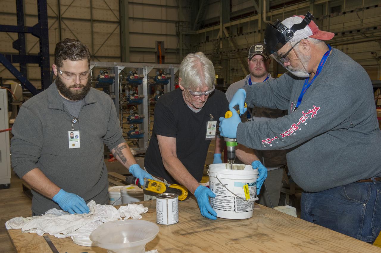
SHELL BUCKLE KNOCKDOWN FACTOR (SBKF) COMPOSITE BARREL EPOXY POUR.
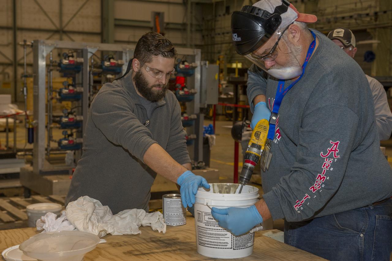
SHELL BUCKLE KNOCKDOWN FACTOR (SBKF) COMPOSITE BARREL EPOXY POUR.
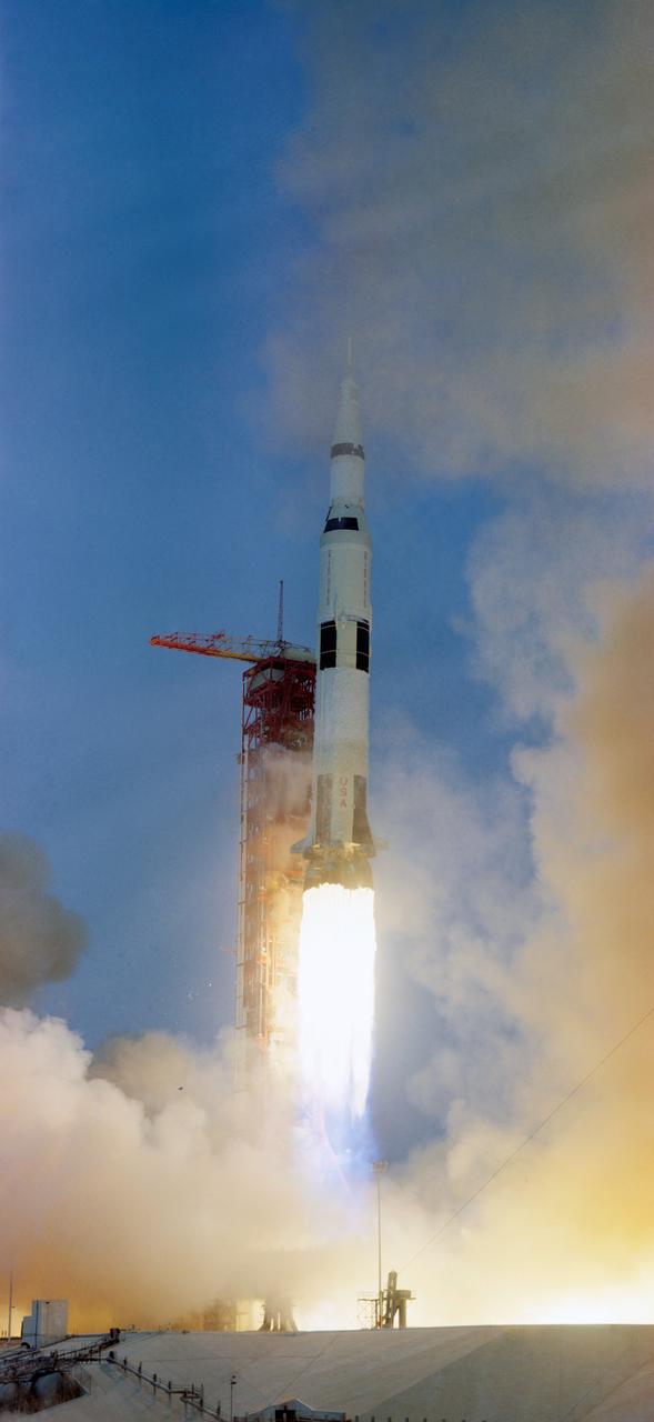
S70-34854 (11 April 1970) --- The Apollo 13 (Spacecraft 109/Lunar Module 7/Saturn 508) space vehicle is launched from Pad A, Launch Complex 39, Kennedy Space Center (KSC), at 2:13 p.m. (EST), April 11, 1970. The crew of the National Aeronautics and Space Administration's (NASA) third lunar landing mission are astronauts James A. Lovell Jr., commander; John L. Swigert Jr., command module pilot; and Fred W. Haise Jr., lunar module pilot.
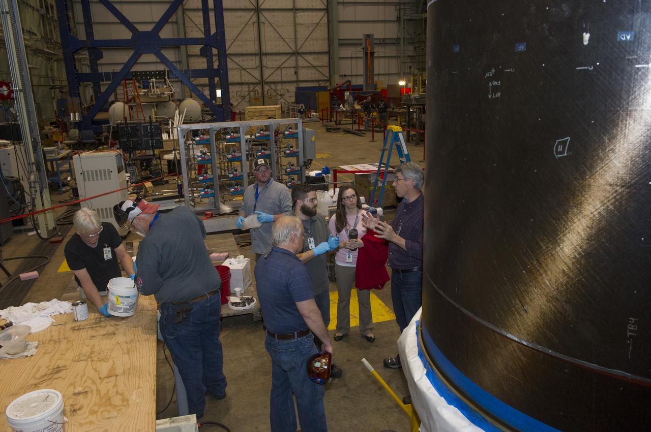
SHELL BUCKLE KNOCKDOWN FACTOR (SBKF) COMPOSITE BARREL EPOXY POUR.
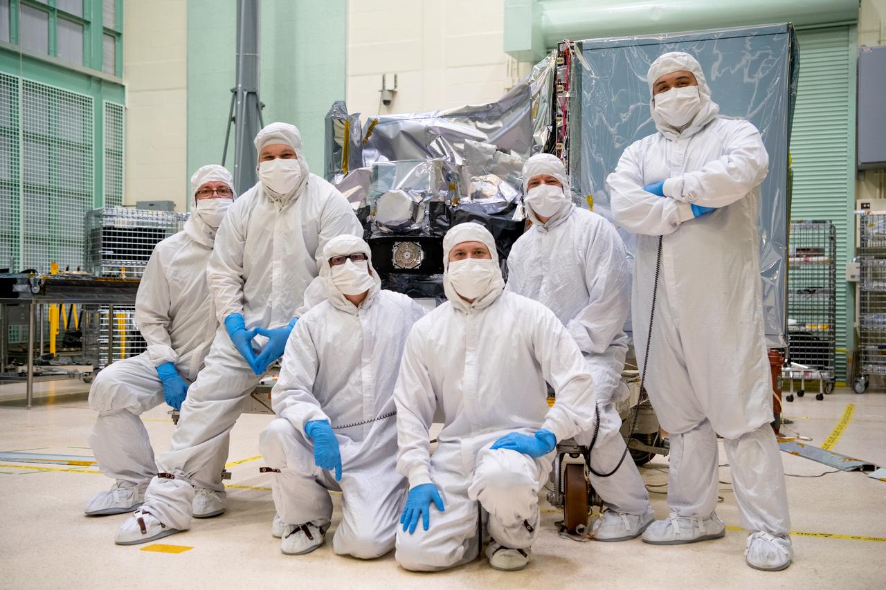
The Ocean Color Instrument (OCI) mechanical technician team pose in front of the instrument after successfully installing the earth shade. OCI is a highly advanced optical spectrometer that will be used to measure properties of light over portions of the electromagnetic spectrum. It will enable continuous measurement of light at finer wavelength resolution than previous NASA satellite sensors, extending key system ocean color data records for climate studies. OCI is PACE's (Plankton, Aerosol, Cloud, ocean Ecosystem) primary sensor built at Goddard Space Flight Center in Greenbelt, MD.
Technicians install components that will aid with guidance, navigation and control of NASA Juno spacecraft.
A technician works on the installation of the PDS Pallet (gold colored box that he is holding) on NASA’s X-59 Quiet SuperSonic Technology or QueSST aircraft. Lockheed Martin Photography By Garry Tice 1011 Lockheed Way, Palmdale, Ca. 93599 Event: SEG 450 Mid Bay - PDS Fit Check Date: 5/03/2021

Technicians complete foaming around the area of Atlantis, Orbiter Vehicle (OV) 104, 17 inch diameter external tank (ET) feed line in preparation for the second liquid hydrogen tanking test at the Kennedy Space Center (KSC). An elaborate network of sensors, leak detectors, and baggies were set up on OV-104 by technicians. Engineers hope this extra instrumentation will help pinpoint the exact location of the leak. OV-104 is scheduled to be launched for the STS-38 mission, a classified Department of Defense (DOD) flight. View provided by KSC with alternate number KSC-90PC-988.

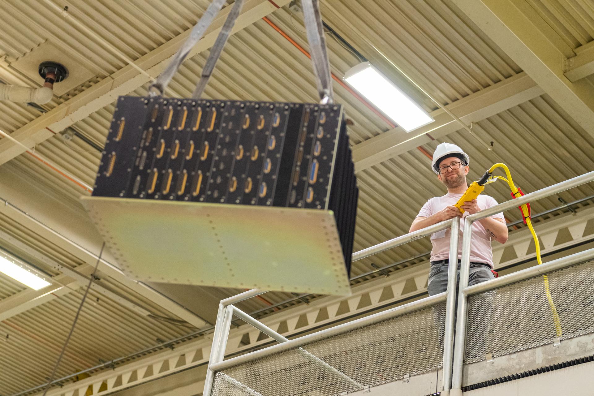
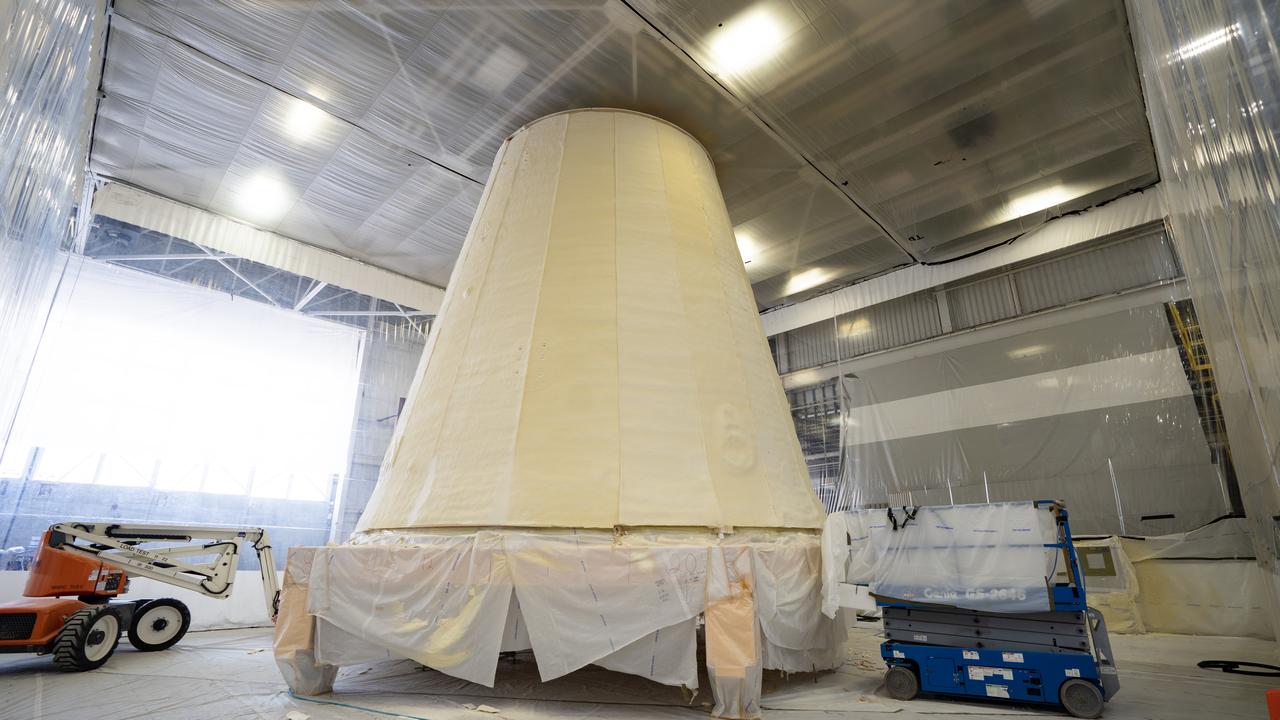
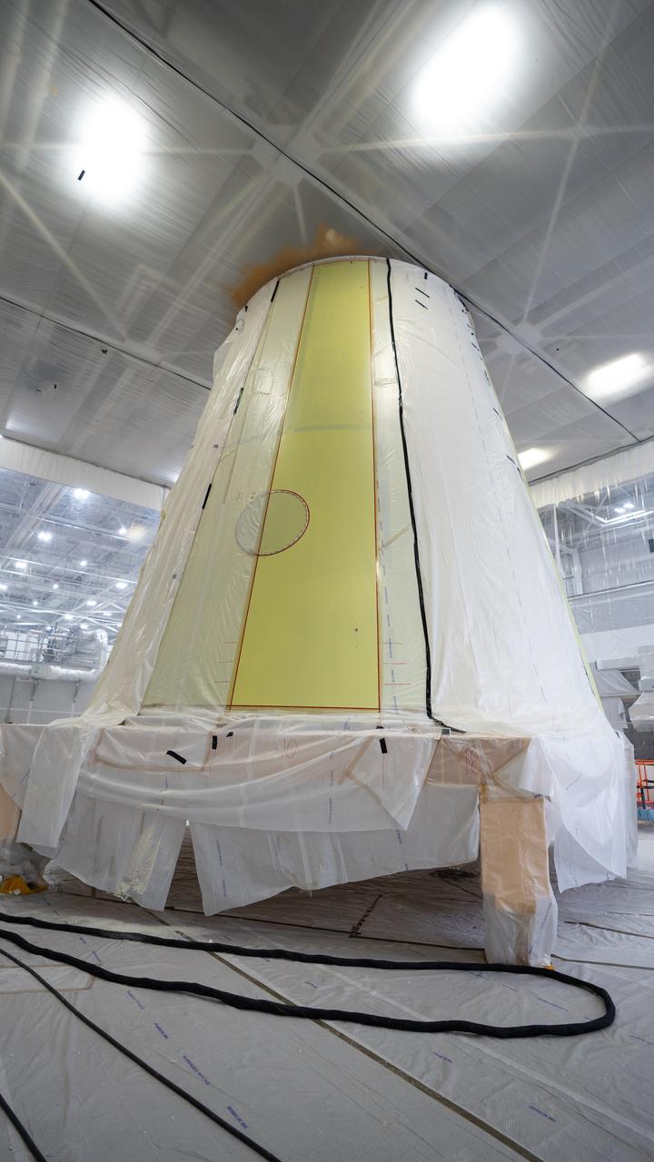
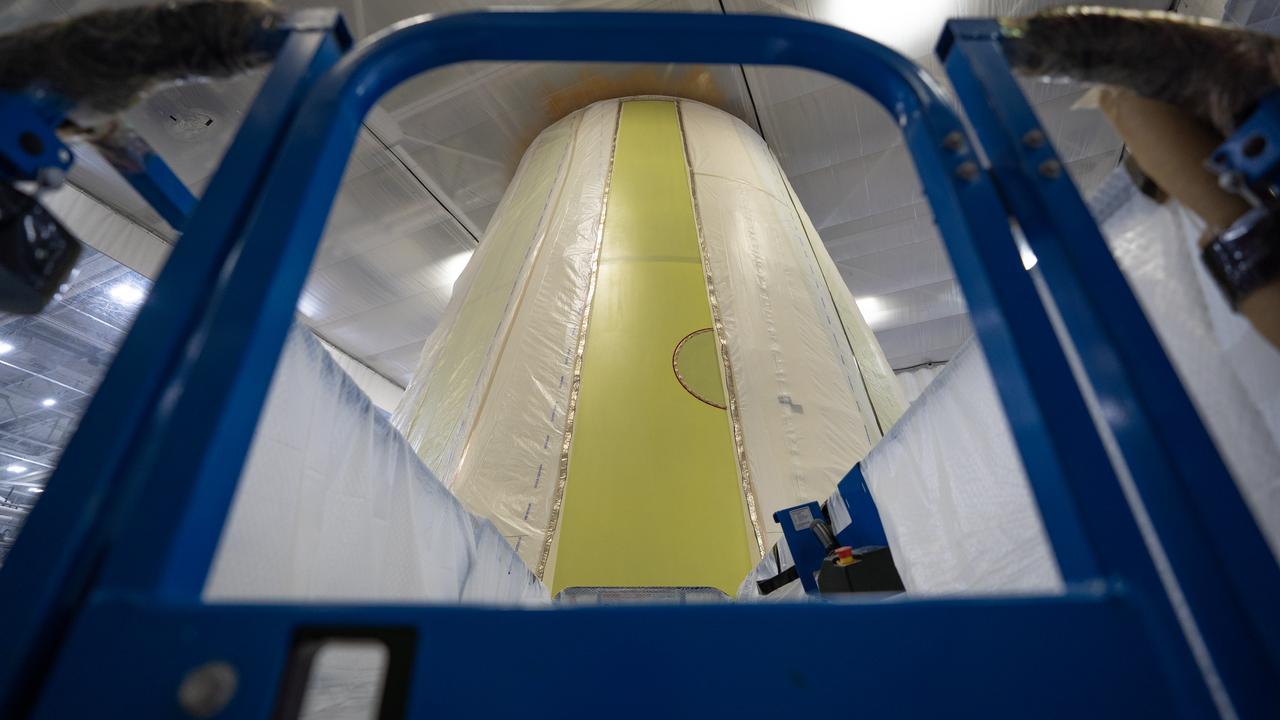
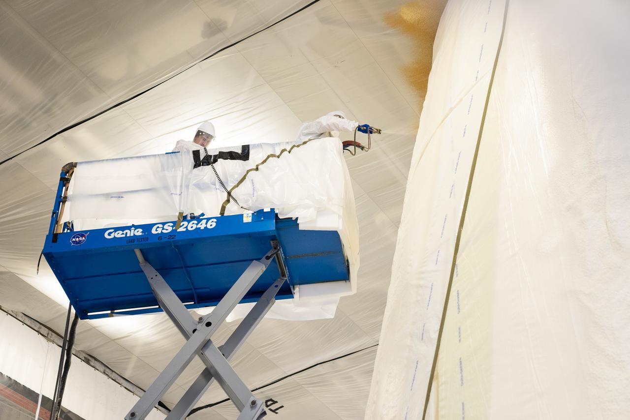
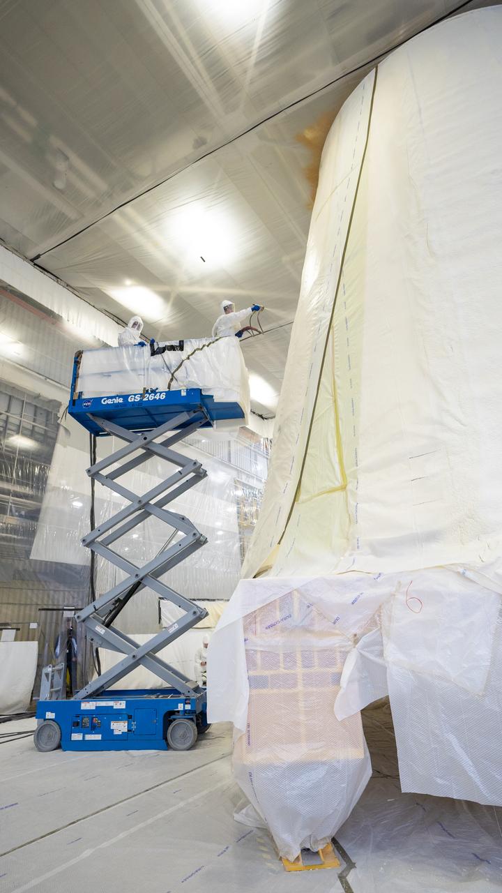
These photos show how technicians at NASA’s Marshall Space Flight Center in Huntsville, Alabama, have applied the thermal protection system material to the launch vehicle stage adapter (LVSA) of NASA’s SLS (Space Launch System) rocket for Artemis III, which will land astronauts on the Moon to advance long-term lunar exploration and scientific discovery and inspire the Artemis Generation. The LVSA is a cone-shaped element that connects the mega rocket’s core stage to its interim cryogenic propulsion stage (ICPS), partially enclosing it and protecting its avionics and electrical systems from the extreme pressures, sounds, and temperatures during launch and flight. Teams at Marshall began applying the thermal protection system material in the spring of 2023. Unlike other parts of the SLS rocket, the thermal protection system material for the LVSA is applied entirely by hand using a spray gun. During application, the technicians use a thin measuring rod to gauge the proper thickness. Once the thermal protection system has cured, certain areas are sanded down to meet parameters. The entire process takes several months. The LVSA is fully manufactured at Marshall by NASA, lead contractor Teledyne Brown Engineering, and the Jacobs Space Group’s ESSCA contract. The LVSA for Artemis III is the last of its kind as future SLS rockets will transition to its next, more powerful Block 1B configuration beginning with Artemis IV. NASA is working to land the first woman and first person of color on the Moon under Artemis. SLS is part of NASA’s backbone for deep space exploration, along with the Orion spacecraft, advanced spacesuits and rovers, the Gateway in orbit around the Moon, and commercial human landing systems. SLS is the only rocket that can send Orion, astronauts, and supplies to the Moon in a single mission.
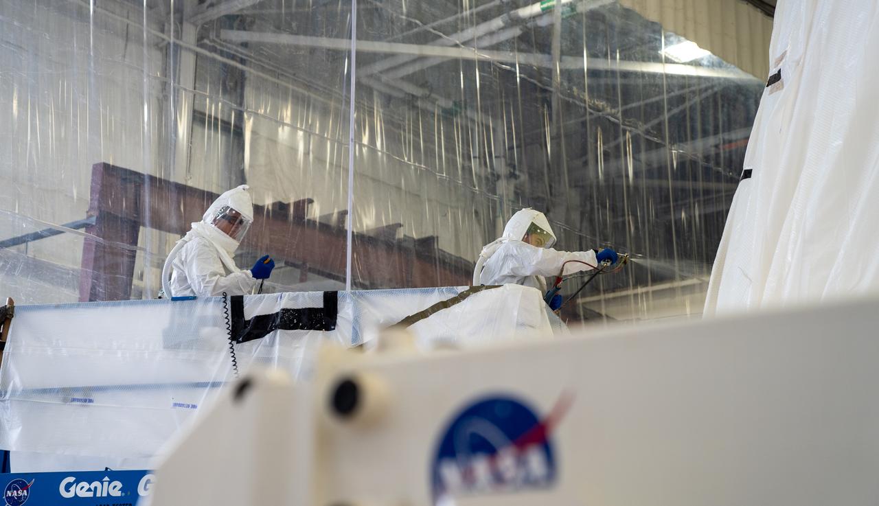
These photos show how technicians at NASA’s Marshall Space Flight Center in Huntsville, Alabama, have applied the thermal protection system material to the launch vehicle stage adapter (LVSA) of NASA’s SLS (Space Launch System) rocket for Artemis III, which will land astronauts on the Moon to advance long-term lunar exploration and scientific discovery and inspire the Artemis Generation. The LVSA is a cone-shaped element that connects the mega rocket’s core stage to its interim cryogenic propulsion stage (ICPS), partially enclosing it and protecting its avionics and electrical systems from the extreme pressures, sounds, and temperatures during launch and flight. Teams at Marshall began applying the thermal protection system material in the spring of 2023. Unlike other parts of the SLS rocket, the thermal protection system material for the LVSA is applied entirely by hand using a spray gun. During application, the technicians use a thin measuring rod to gauge the proper thickness. Once the thermal protection system has cured, certain areas are sanded down to meet parameters. The entire process takes several months. The LVSA is fully manufactured at Marshall by NASA, lead contractor Teledyne Brown Engineering, and the Jacobs Space Group’s ESSCA contract. The LVSA for Artemis III is the last of its kind as future SLS rockets will transition to its next, more powerful Block 1B configuration beginning with Artemis IV. NASA is working to land the first woman and first person of color on the Moon under Artemis. SLS is part of NASA’s backbone for deep space exploration, along with the Orion spacecraft, advanced spacesuits and rovers, the Gateway in orbit around the Moon, and commercial human landing systems. SLS is the only rocket that can send Orion, astronauts, and supplies to the Moon in a single mission.
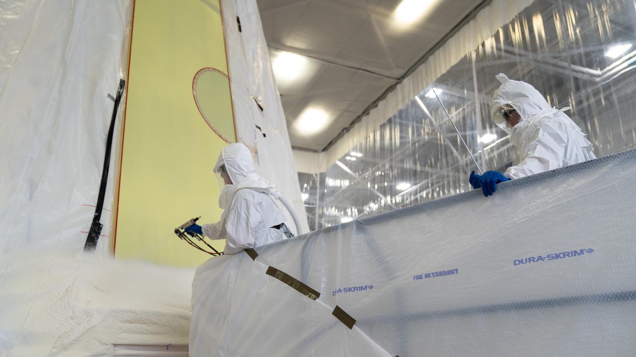
These photos show how technicians at NASA’s Marshall Space Flight Center in Huntsville, Alabama, have applied the thermal protection system material to the launch vehicle stage adapter (LVSA) of NASA’s SLS (Space Launch System) rocket for Artemis III, which will land astronauts on the Moon to advance long-term lunar exploration and scientific discovery and inspire the Artemis Generation. The LVSA is a cone-shaped element that connects the mega rocket’s core stage to its interim cryogenic propulsion stage (ICPS), partially enclosing it and protecting its avionics and electrical systems from the extreme pressures, sounds, and temperatures during launch and flight. Teams at Marshall began applying the thermal protection system material in the spring of 2023. Unlike other parts of the SLS rocket, the thermal protection system material for the LVSA is applied entirely by hand using a spray gun. During application, the technicians use a thin measuring rod to gauge the proper thickness. Once the thermal protection system has cured, certain areas are sanded down to meet parameters. The entire process takes several months. The LVSA is fully manufactured at Marshall by NASA, lead contractor Teledyne Brown Engineering, and the Jacobs Space Group’s ESSCA contract. The LVSA for Artemis III is the last of its kind as future SLS rockets will transition to its next, more powerful Block 1B configuration beginning with Artemis IV. NASA is working to land the first woman and first person of color on the Moon under Artemis. SLS is part of NASA’s backbone for deep space exploration, along with the Orion spacecraft, advanced spacesuits and rovers, the Gateway in orbit around the Moon, and commercial human landing systems. SLS is the only rocket that can send Orion, astronauts, and supplies to the Moon in a single mission.
These photos show how technicians at NASA’s Marshall Space Flight Center in Huntsville, Alabama, have applied the thermal protection system material to the launch vehicle stage adapter (LVSA) of NASA’s SLS (Space Launch System) rocket for Artemis III, which will land astronauts on the Moon to advance long-term lunar exploration and scientific discovery and inspire the Artemis Generation. The LVSA is a cone-shaped element that connects the mega rocket’s core stage to its interim cryogenic propulsion stage (ICPS), partially enclosing it and protecting its avionics and electrical systems from the extreme pressures, sounds, and temperatures during launch and flight. Teams at Marshall began applying the thermal protection system material in the spring of 2023. Unlike other parts of the SLS rocket, the thermal protection system material for the LVSA is applied entirely by hand using a spray gun. During application, the technicians use a thin measuring rod to gauge the proper thickness. Once the thermal protection system has cured, certain areas are sanded down to meet parameters. The entire process takes several months. The LVSA is fully manufactured at Marshall by NASA, lead contractor Teledyne Brown Engineering, and the Jacobs Space Group’s ESSCA contract. The LVSA for Artemis III is the last of its kind as future SLS rockets will transition to its next, more powerful Block 1B configuration beginning with Artemis IV. NASA is working to land the first woman and first person of color on the Moon under Artemis. SLS is part of NASA’s backbone for deep space exploration, along with the Orion spacecraft, advanced spacesuits and rovers, the Gateway in orbit around the Moon, and commercial human landing systems. SLS is the only rocket that can send Orion, astronauts, and supplies to the Moon in a single mission.
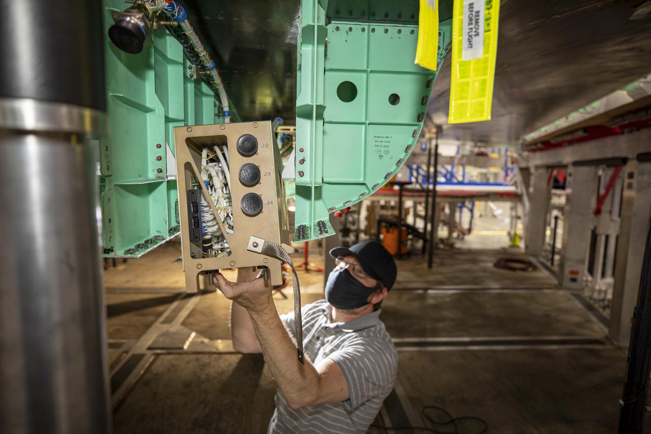
These photos show the launch vehicle stage adapter (LVSA) of NASA’s SLS (Space Launch System) rocket for Artemis III before technicians at NASA’s Marshall Space Flight Center in Huntsville, Alabama, applied the thermal protection system to it. Artemis III will land astronauts on the Moon to advance long-term lunar exploration and scientific discover and inspire the Artemis Generation. Teams at Marshall began applying the thermal protection system material in the spring of 2023. Unlike other parts of the SLS rocket, the thermal protection system material for the LVSA is applied entirely by hand using a spray gun. During application, the technicians use a thin measuring rod to gauge the proper thickness. Once the thermal protection system has cured, certain areas are sanded down to meet parameters. The entire process takes several months. The LVSA is fully manufactured at Marshall by NASA, lead contractor Teledyne Brown Engineering, and the Jacobs Space Group’s ESSCA contract. The LVSA for Artemis III is the last of its kind as future SLS rockets will transition to its next, more powerful Block 1B configuration beginning with Artemis IV. NASA is working to land the first woman and first person of color on the Moon under Artemis. SLS is part of NASA’s backbone for deep space exploration, along with the Orion spacecraft, advanced spacesuits and rovers, the Gateway in orbit around the Moon, and commercial human landing systems. SLS is the only rocket that can send Orion, astronauts, and supplies to the Moon in a single mission.
These photos show the launch vehicle stage adapter (LVSA) of NASA’s SLS (Space Launch System) rocket for Artemis III before technicians at NASA’s Marshall Space Flight Center in Huntsville, Alabama, applied the thermal protection system to it. Artemis III will land astronauts on the Moon to advance long-term lunar exploration and scientific discover and inspire the Artemis Generation. Teams at Marshall began applying the thermal protection system material in the spring of 2023. Unlike other parts of the SLS rocket, the thermal protection system material for the LVSA is applied entirely by hand using a spray gun. During application, the technicians use a thin measuring rod to gauge the proper thickness. Once the thermal protection system has cured, certain areas are sanded down to meet parameters. The entire process takes several months. The LVSA is fully manufactured at Marshall by NASA, lead contractor Teledyne Brown Engineering, and the Jacobs Space Group’s ESSCA contract. The LVSA for Artemis III is the last of its kind as future SLS rockets will transition to its next, more powerful Block 1B configuration beginning with Artemis IV. NASA is working to land the first woman and first person of color on the Moon under Artemis. SLS is part of NASA’s backbone for deep space exploration, along with the Orion spacecraft, advanced spacesuits and rovers, the Gateway in orbit around the Moon, and commercial human landing systems. SLS is the only rocket that can send Orion, astronauts, and supplies to the Moon in a single mission.
These photos show how technicians at NASA’s Marshall Space Flight Center in Huntsville, Alabama, have applied the thermal protection system material to the launch vehicle stage adapter (LVSA) of NASA’s SLS (Space Launch System) rocket for Artemis III, which will land astronauts on the Moon to advance long-term lunar exploration and scientific discovery and inspire the Artemis Generation. The LVSA is a cone-shaped element that connects the mega rocket’s core stage to its interim cryogenic propulsion stage (ICPS), partially enclosing it and protecting its avionics and electrical systems from the extreme pressures, sounds, and temperatures during launch and flight. Teams at Marshall began applying the thermal protection system material in the spring of 2023. Unlike other parts of the SLS rocket, the thermal protection system material for the LVSA is applied entirely by hand using a spray gun. During application, the technicians use a thin measuring rod to gauge the proper thickness. Once the thermal protection system has cured, certain areas are sanded down to meet parameters. The entire process takes several months. The LVSA is fully manufactured at Marshall by NASA, lead contractor Teledyne Brown Engineering, and the Jacobs Space Group’s ESSCA contract. The LVSA for Artemis III is the last of its kind as future SLS rockets will transition to its next, more powerful Block 1B configuration beginning with Artemis IV. NASA is working to land the first woman and first person of color on the Moon under Artemis. SLS is part of NASA’s backbone for deep space exploration, along with the Orion spacecraft, advanced spacesuits and rovers, the Gateway in orbit around the Moon, and commercial human landing systems. SLS is the only rocket that can send Orion, astronauts, and supplies to the Moon in a single mission.
These photos show how technicians at NASA’s Marshall Space Flight Center in Huntsville, Alabama, have applied the thermal protection system material to the launch vehicle stage adapter (LVSA) of NASA’s SLS (Space Launch System) rocket for Artemis III, which will land astronauts on the Moon to advance long-term lunar exploration and scientific discovery and inspire the Artemis Generation. The LVSA is a cone-shaped element that connects the mega rocket’s core stage to its interim cryogenic propulsion stage (ICPS), partially enclosing it and protecting its avionics and electrical systems from the extreme pressures, sounds, and temperatures during launch and flight. Teams at Marshall began applying the thermal protection system material in the spring of 2023. Unlike other parts of the SLS rocket, the thermal protection system material for the LVSA is applied entirely by hand using a spray gun. During application, the technicians use a thin measuring rod to gauge the proper thickness. Once the thermal protection system has cured, certain areas are sanded down to meet parameters. The entire process takes several months. The LVSA is fully manufactured at Marshall by NASA, lead contractor Teledyne Brown Engineering, and the Jacobs Space Group’s ESSCA contract. The LVSA for Artemis III is the last of its kind as future SLS rockets will transition to its next, more powerful Block 1B configuration beginning with Artemis IV. NASA is working to land the first woman and first person of color on the Moon under Artemis. SLS is part of NASA’s backbone for deep space exploration, along with the Orion spacecraft, advanced spacesuits and rovers, the Gateway in orbit around the Moon, and commercial human landing systems. SLS is the only rocket that can send Orion, astronauts, and supplies to the Moon in a single mission.
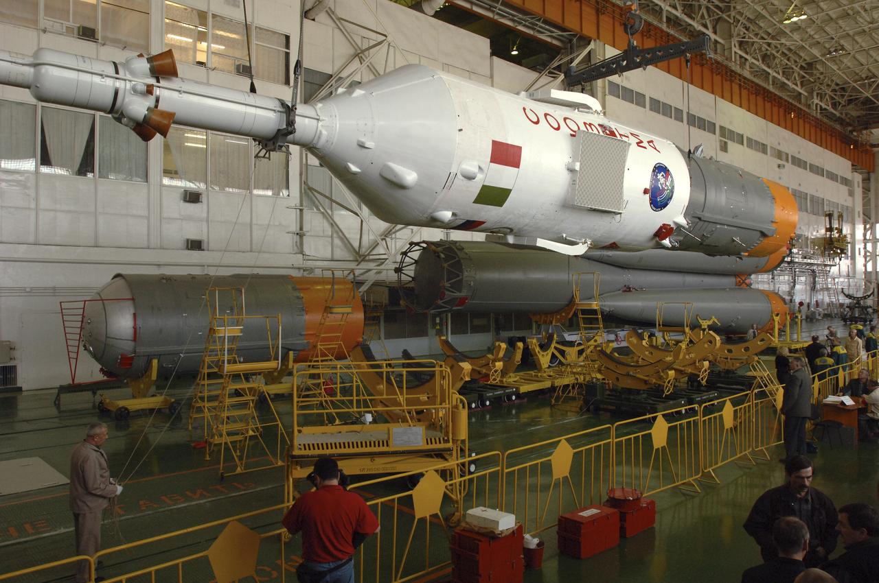
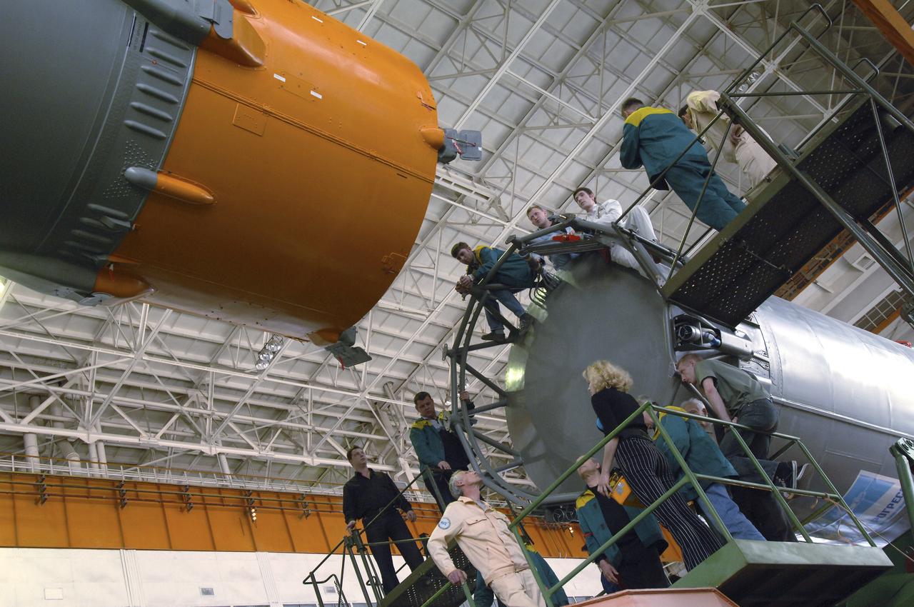
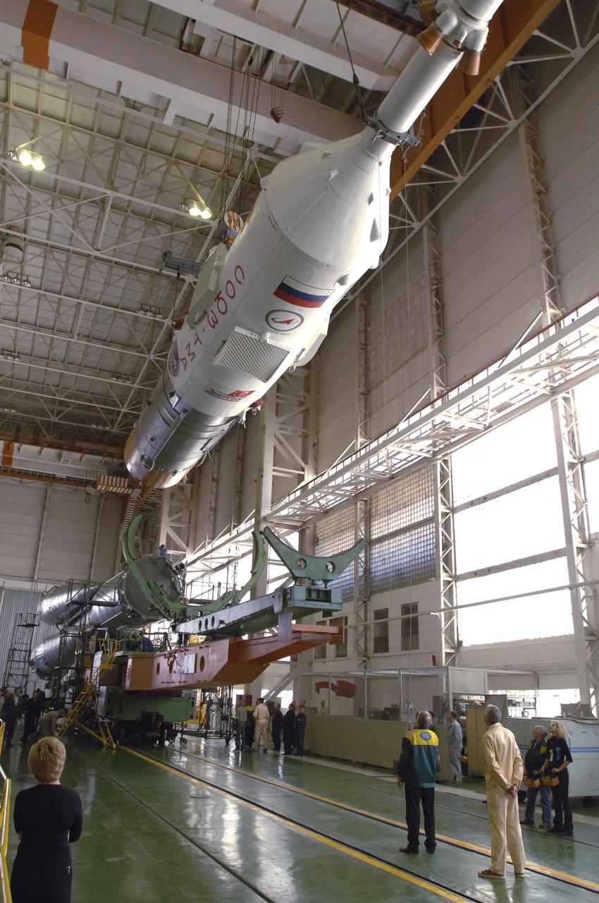
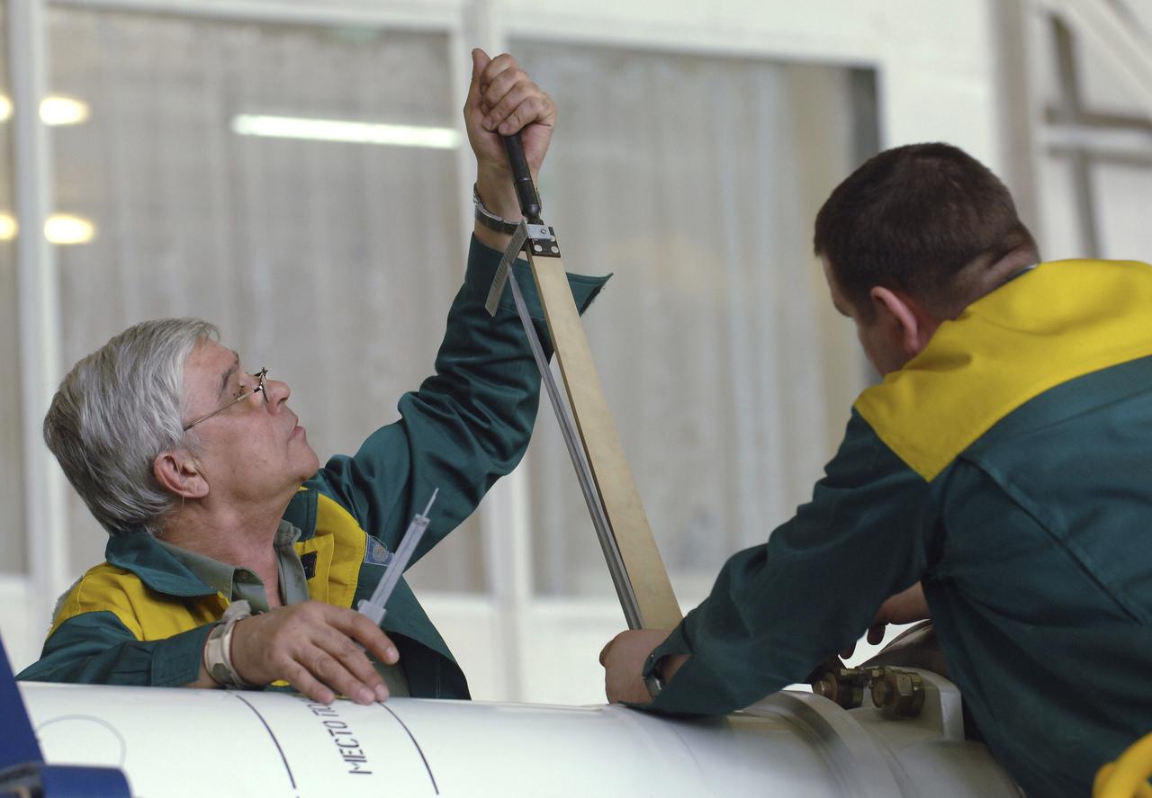
Russian technicians work, Tuesday, April 12, 2005, on mating the Soyuz TMA-6 spacecraft to the booster rocket inside the integration facility at the Baikonur Cosmodrome in Kazakhstan as preparations continued for the April 15 launch of Expedition 11 with Commander Sergei Krikalev, Flight Engineer John Phillips and European Space Agency Astronaut Roberto Vittori, of Italy, to the International Space Station. The rocket mating operation occurred on the 44th anniversary of the launch of Yuri Gagarin from the same complex to become the first human in space. Photo Credit: (NASA/Bill Ingalls)
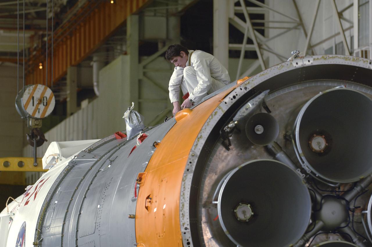
A Russian technician works, Tuesday, April 12, 2005, on mating the Soyuz TMA-6 spacecraft to the booster rocket inside the integration facility at the Baikonur Cosmodrome in Kazakhstan as preparations continued for the April 15 launch of Expedition 11 with Commander Sergei Krikalev, Flight Engineer John Phillips and European Space Agency Astronaut Roberto Vittori, of Italy, to the International Space Station. The rocket mating operation occurred on the 44th anniversary of the launch of Yuri Gagarin from the same complex to become the first human in space. Photo Credit: (NASA/Bill Ingalls)
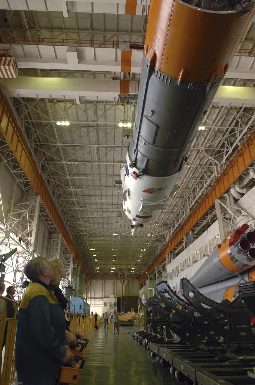
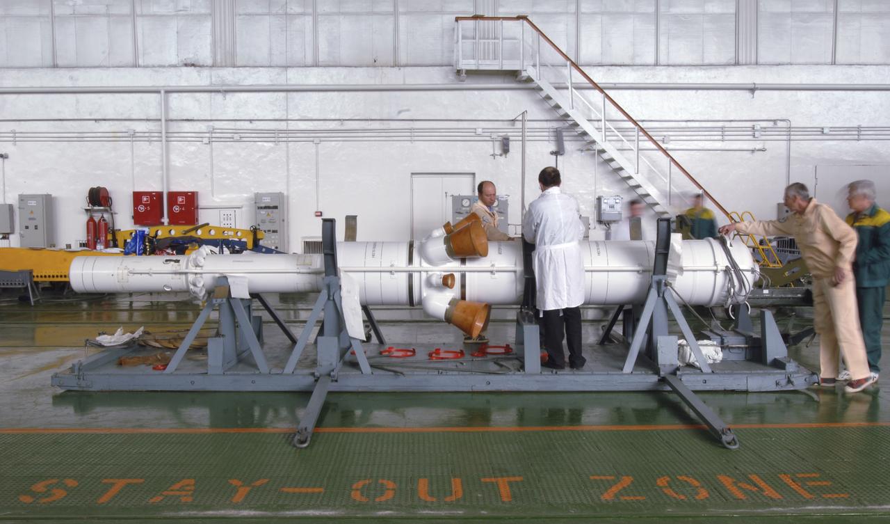
Russian technicians work, Tuesday, April 12, 2005, on mating the Soyuz TMA-6 spacecraft to the booster rocket inside the integration facility at the Baikonur Cosmodrome in Kazakhstan as preparations continued for the April 15 launch of Expedition 11 with Commander Sergei Krikalev, Flight Engineer John Phillips and European Space Agency Astronaut Roberto Vittori, of Italy, to the International Space Station. The rocket mating operation occurred on the 44th anniversary of the launch of Yuri Gagarin from the same complex to become the first human in space. Photo Credit: (NASA/Bill Ingalls)
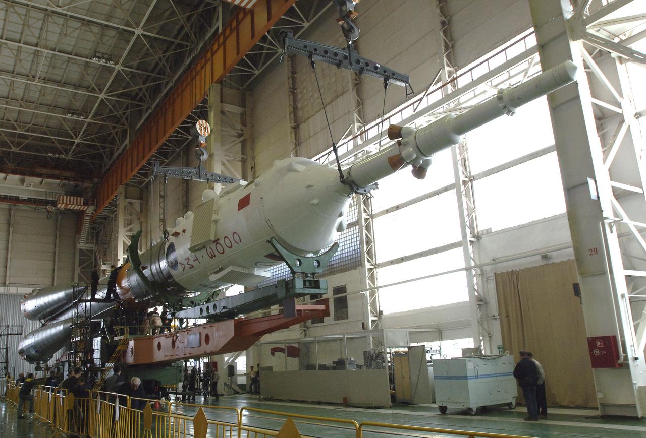
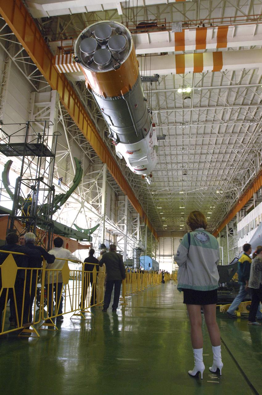
Russian technicians work, Tuesday, April 12, 2005, on mating the Soyuz TMA-6 spacecraft to the booster rocket inside the integration facility at the Baikonur Cosmodrome in Kazakhstan as preparations continued for the April 15 launch of Expedition 11 with Commander Sergei Krikalev, Flight Engineer John Phillips and European Space Agency Astronaut Roberto Vittori, of Italy, to the International Space Station. The rocket mating operation occurred on the 44th anniversary of the launch of Yuri Gagarin from the same complex to become the first human in space. Photo Credit: (NASA/Bill Ingalls)
Russian technicians work, Tuesday, April 12, 2005, on mating the Soyuz TMA-6 spacecraft to the booster rocket inside the integration facility at the Baikonur Cosmodrome in Kazakhstan as preparations continued for the April 15 launch of Expedition 11 with Commander Sergei Krikalev, Flight Engineer John Phillips and European Space Agency Astronaut Roberto Vittori, of Italy, to the International Space Station. The rocket mating operation occurred on the 44th anniversary of the launch of Yuri Gagarin from the same complex to become the first human in space. Photo Credit: (NASA/Bill Ingalls)
Russian technicians work, Tuesday, April 12, 2005, on mating the Soyuz TMA-6 spacecraft to the booster rocket inside the integration facility at the Baikonur Cosmodrome in Kazakhstan as preparations continued for the April 15 launch of Expedition 11 with Commander Sergei Krikalev, Flight Engineer John Phillips and European Space Agency Astronaut Roberto Vittori, of Italy, to the International Space Station. The rocket mating operation occurred on the 44th anniversary of the launch of Yuri Gagarin from the same complex to become the first human in space. Photo Credit: (NASA/Bill Ingalls)
Russian technicians work, Tuesday, April 12, 2005, on mating the Soyuz TMA-6 spacecraft to the booster rocket inside the integration facility at the Baikonur Cosmodrome in Kazakhstan as preparations continued for the April 15 launch of Expedition 11 with Commander Sergei Krikalev, Flight Engineer John Phillips and European Space Agency Astronaut Roberto Vittori, of Italy, to the International Space Station. The rocket mating operation occurred on the 44th anniversary of the launch of Yuri Gagarin from the same complex to become the first human in space. Photo Credit: (NASA/Bill Ingalls)
Russian technicians work, Tuesday, April 12, 2005, on mating the Soyuz TMA-6 spacecraft to the booster rocket inside the integration facility at the Baikonur Cosmodrome in Kazakhstan as preparations continued for the April 15 launch of Expedition 11 with Commander Sergei Krikalev, Flight Engineer John Phillips and European Space Agency Astronaut Roberto Vittori, of Italy, to the International Space Station. The rocket mating operation occurred on the 44th anniversary of the launch of Yuri Gagarin from the same complex to become the first human in space. Photo Credit: (NASA/Bill Ingalls)
Russian technicians work, Tuesday, April 12, 2005, on mating the Soyuz TMA-6 spacecraft to the booster rocket inside the integration facility at the Baikonur Cosmodrome in Kazakhstan as preparations continued for the April 15 launch of Expedition 11 with Commander Sergei Krikalev, Flight Engineer John Phillips and European Space Agency Astronaut Roberto Vittori, of Italy, to the International Space Station. The rocket mating operation occurred on the 44th anniversary of the launch of Yuri Gagarin from the same complex to become the first human in space. Photo Credit: (NASA/Bill Ingalls)
Russian technicians work, Tuesday, April 12, 2005, on mating the Soyuz TMA-6 spacecraft to the booster rocket inside the integration facility at the Baikonur Cosmodrome in Kazakhstan as preparations continued for the April 15 launch of Expedition 11 with Commander Sergei Krikalev, Flight Engineer John Phillips and European Space Agency Astronaut Roberto Vittori, of Italy, to the International Space Station. The rocket mating operation occurred on the 44th anniversary of the launch of Yuri Gagarin from the same complex to become the first human in space. Photo Credit: (NASA/Bill Ingalls)
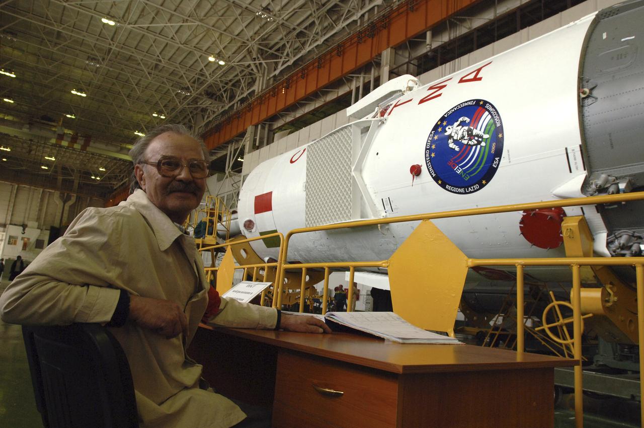
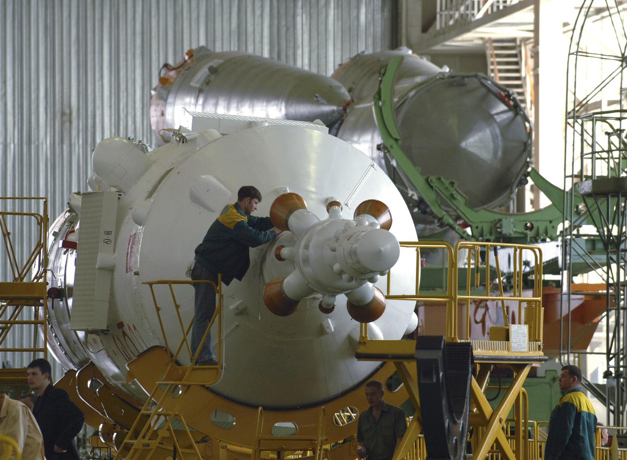
An unidentified Russian technician is seen, Tuesday, April 12, 2005, while the Soyuz TMA-6 spacecraft is mated to the booster rocket inside the integration facility at the Baikonur Cosmodrome in Kazakhstan as preparations continued for the April 15 launch of Expedition 11 with Commander Sergei Krikalev, Flight Engineer John Phillips and European Space Agency Astronaut Roberto Vittori, of Italy, to the International Space Station. The rocket mating operation occurred on the 44th anniversary of the launch of Yuri Gagarin from the same complex to become the first human in space. Photo Credit: (NASA/Bill Ingalls)
Russian technicians work, Tuesday, April 12, 2005, on mating the Soyuz TMA-6 spacecraft to the booster rocket inside the integration facility at the Baikonur Cosmodrome in Kazakhstan as preparations continued for the April 15 launch of Expedition 11 with Commander Sergei Krikalev, Flight Engineer John Phillips and European Space Agency Astronaut Roberto Vittori, of Italy, to the International Space Station. The rocket mating operation occurred on the 44th anniversary of the launch of Yuri Gagarin from the same complex to become the first human in space. Photo Credit: (NASA/Bill Ingalls)
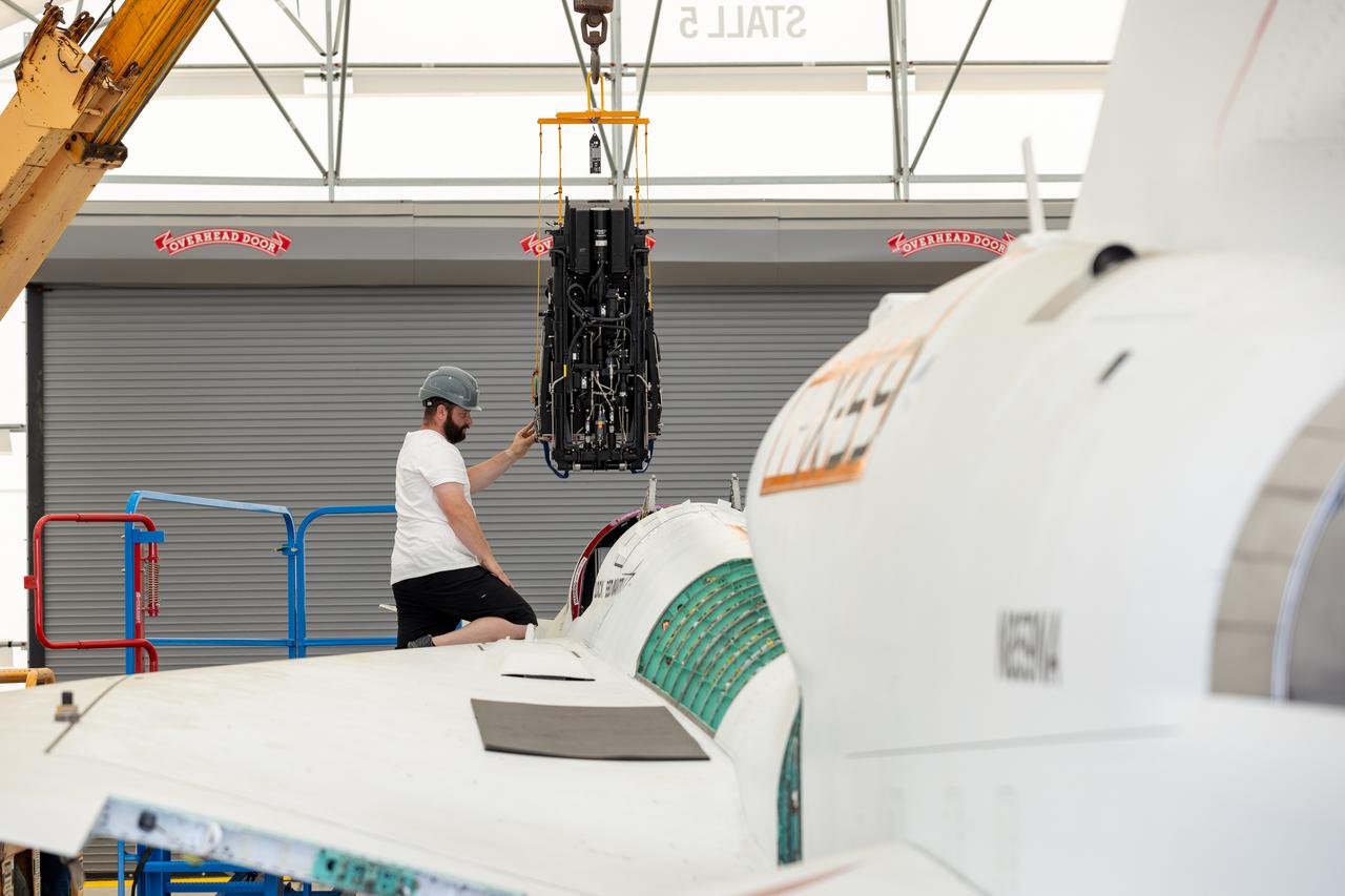
NASA Life Support Technician Mathew Sechler provides support as the X-59’s ejection seat is installed into the aircraft at Lockheed Martin Skunk Works’ facilities in Palmdale, California. Completion of the seat’s installation marks an integration milestone for the aircraft as it prepares for final ground tests.
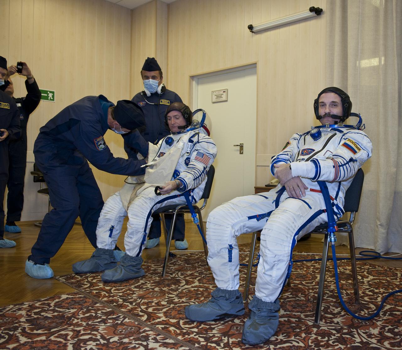
Expedition 25 NASA Flight Engineer Scott Kelly of the U.S., left, and Soyuz Commander Alexander Kaleri have their Russian Sokol suits prepared for launch by technicians at the Baikonur Cosmodrome in Kazakhstan, Friday, Oct. 8, 2010. (Photo Credit: NASA/Carla Cioffi)
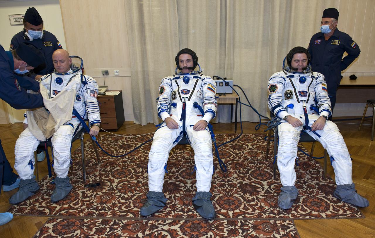
Expedition 25 NASA Flight Engineer Scott Kelly of the U.S., left, Soyuz Commander Alexander Kaleri and Flight Engineer Oleg Skripochka, right, have their Russian Sokol suits prepared for launch by technicians at the Baikonur Cosmodrome in Kazakhstan, Friday, Oct. 8, 2010. (Photo Credit: NASA/Carla Cioffi)
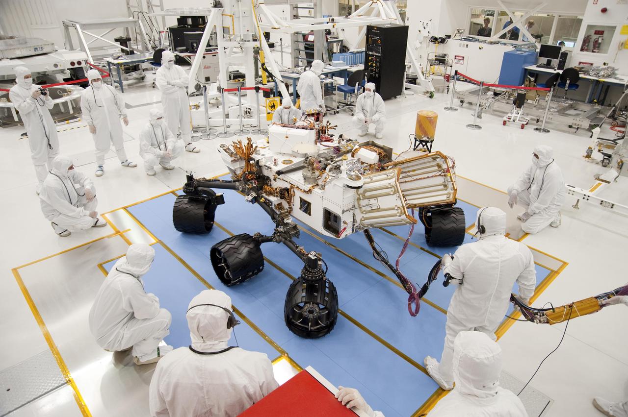
Technicians and engineers in clean-room garb monitor the first drive test of NASA Curiosity rover, on July 23, 2010. Technicians and engineers conducted the drive test at the Jet Propulsion Laboratory in Pasadena, Calif.
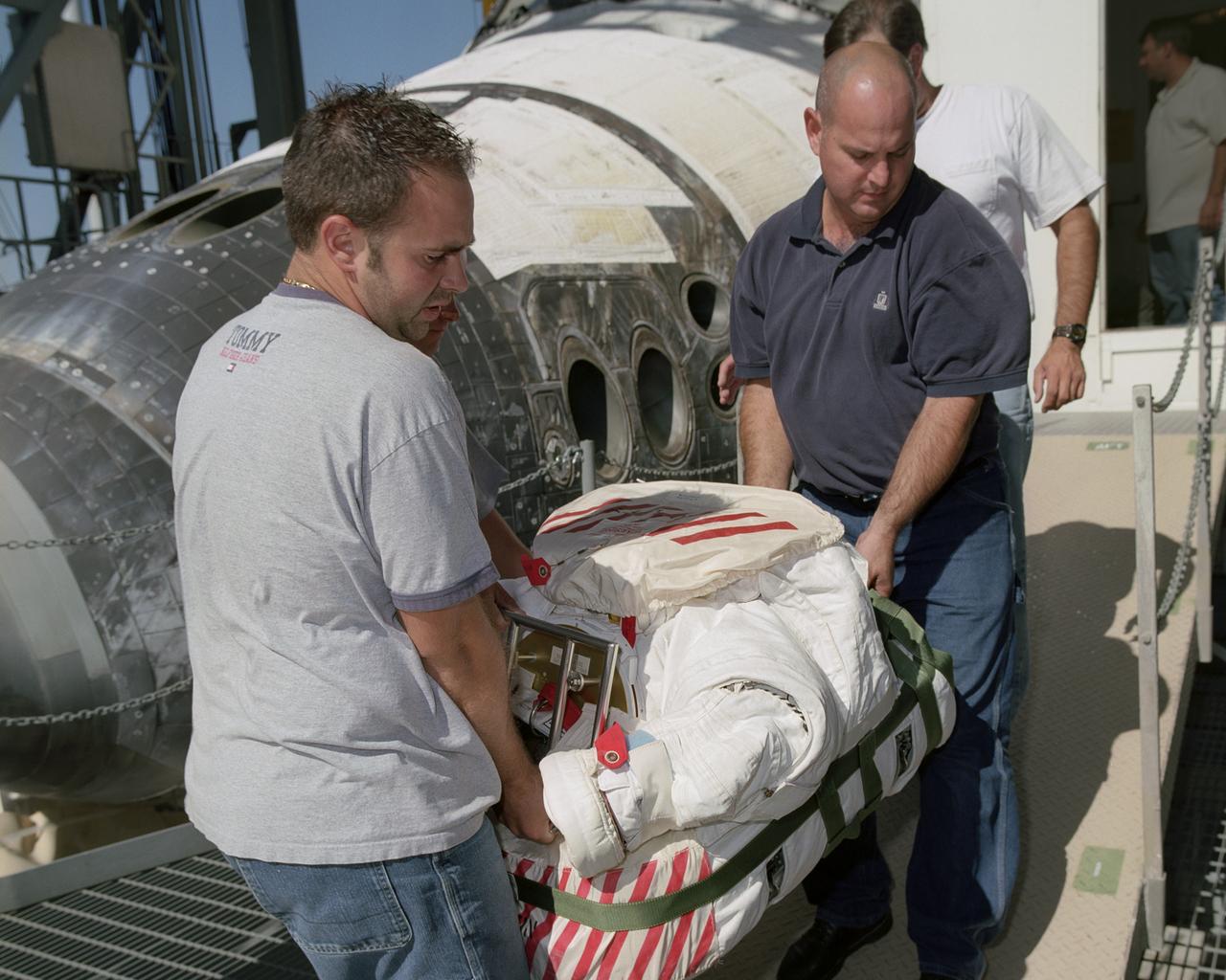
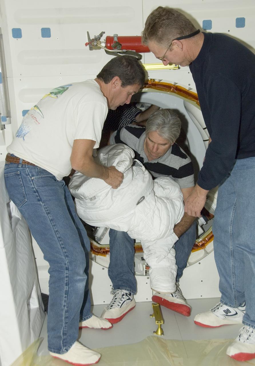
Flight Crew Systems Technicians Ray Smith and Raphael Rodriguez remove one of the Extravehicular Mobility Units, or EMUs, from the Space Shuttle Discovery after it's successful landing at NASA's Dryden Flight Research Center. The Space Shuttles receive post-flight servicing in the Mate-Demate Device (MDD) following landings at NASA's Dryden Flight Research Center, Edwards, California. The gantry-like MDD structure is used for servicing the shuttle orbiters in preparation for their ferry flight back to the Kennedy Space Center in Florida, including mounting the shuttle atop NASA's modified Boeing 747 Shuttle Carrier Aircraft. Space Shuttle Discovery landed safely at NASA's Dryden Flight Research Center at Edwards Air Force Base in California at 5:11:22 a.m. PDT, August 9, 2005, following the very successful 14-day STS-114 return to flight mission. During their two weeks in space, Commander Eileen Collins and her six crewmates tested out new safety procedures and delivered supplies and equipment the International Space Station. Discovery spent two weeks in space, where the crew demonstrated new methods to inspect and repair the Shuttle in orbit. The crew also delivered supplies, outfitted and performed maintenance on the International Space Station. A number of these tasks were conducted during three spacewalks. In an unprecedented event, spacewalkers were called upon to remove protruding gap fillers from the heat shield on Discovery's underbelly. In other spacewalk activities, astronauts installed an external platform onto the Station's Quest Airlock and replaced one of the orbital outpost's Control Moment Gyroscopes. Inside the Station, the STS-114 crew conducted joint operations with the Expedition 11 crew. They unloaded fresh supplies from the Shuttle and the Raffaello Multi-Purpose Logistics Module. Before Discovery undocked, the crews filled Raffeallo with unneeded items and returned to Shuttle payload bay. Discovery launched on July 26 and spent almost 14
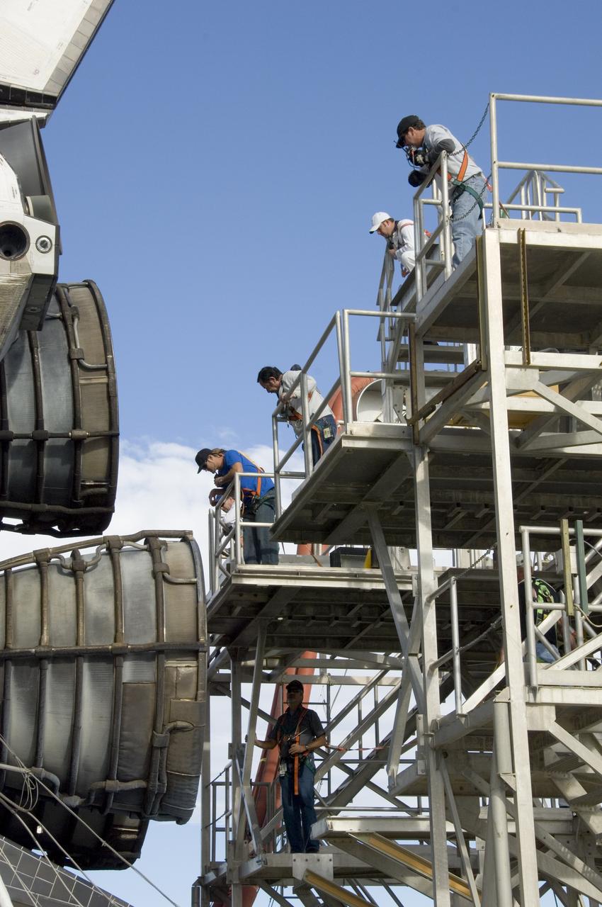
Technicians monitor the positioning of a large workstand as it is carefully moved into place around the main engine nozzles of Space Shuttle Endeavour during deservicing and ferry flight preparations at NASA's Dryden Flight Research Center at Edwards Air Force Base.
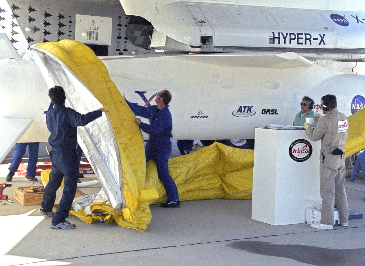
Orbital Sciences Corp. technicians remove protective shrouds from the modified Pegasus booster before takeoff on the X-43A's Mach 9.6 record scramjet flight.

NASA Dryden life support technician Jim Sokolik assists pressure-suited pilot Dee Porter into the cockpit of NASA's ER-2 Earth resources aircraft.
NASA avionics technicians Randy Wagner and Terry Bishop make final adjustments on the scramjet-powered X-43A before its record Mach 9.6 flight.
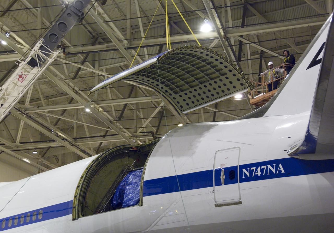
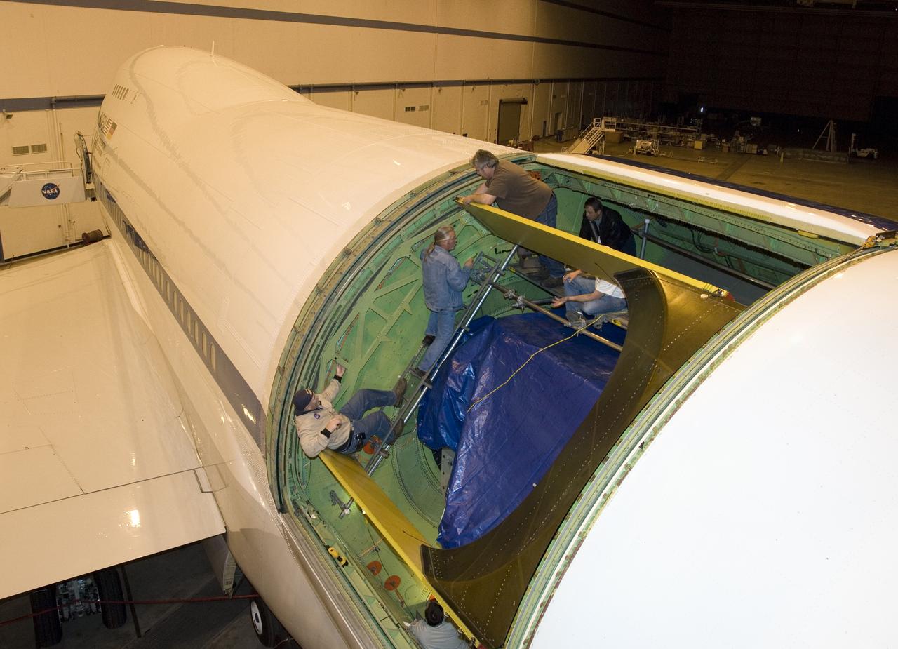
Technicians guide removal of the upper rigid door assembly that covers the telescope cavity on NASA's SOFIA 747SP in preparation for primary mirror removal.
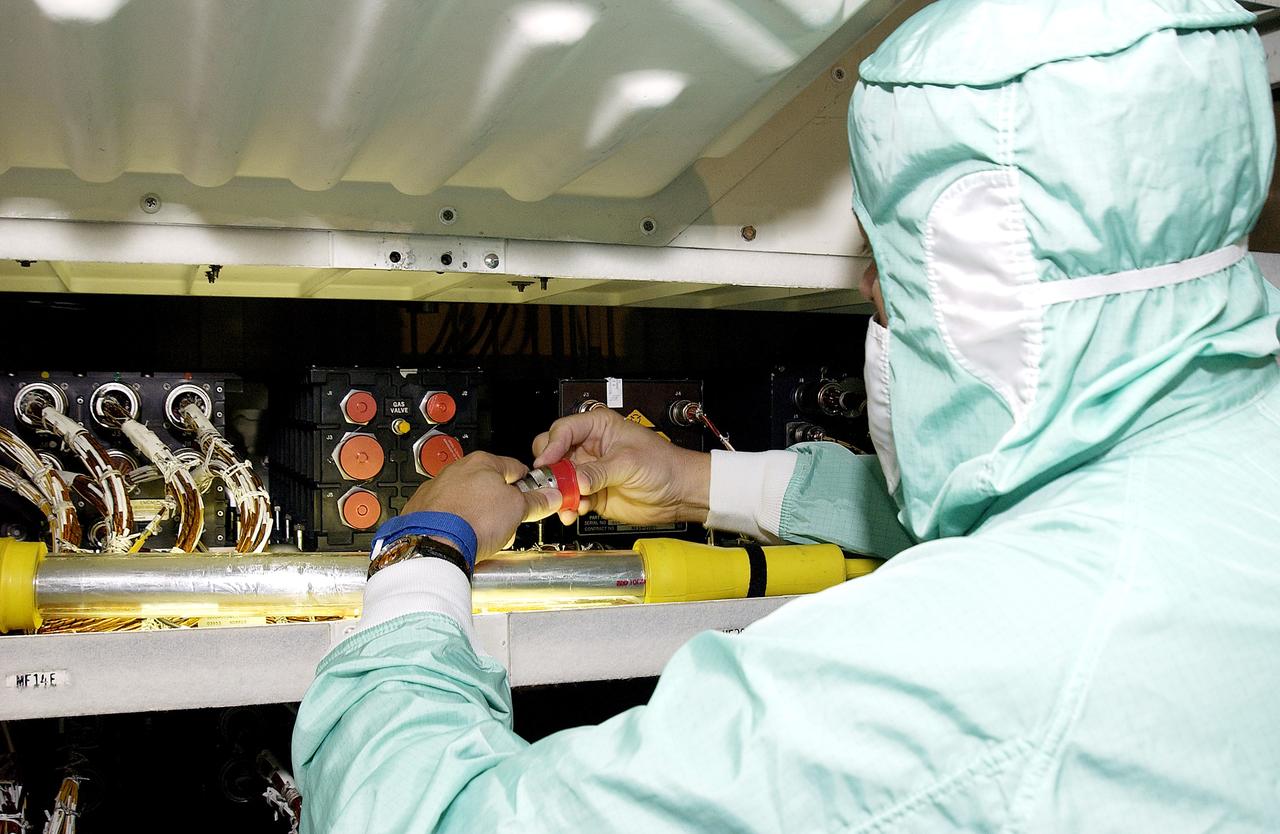
KENNEDY SPACE CENTER, FLA. - A technician with United Space Alliance checks wiring in the mid-body and flight deck of orbiter Atlantis as part of routine maintenance.

KENNEDY SPACE CENTER, FLA. - A technician with United Space Alliance checks wiring in the mid-body of orbiter Atlantis as part of routine maintenance.
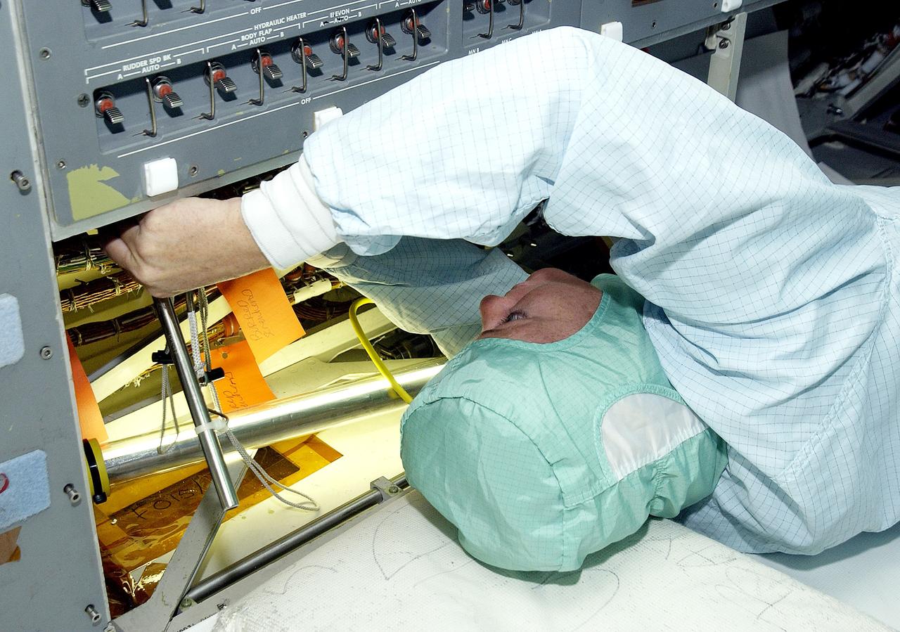
KENNEDY SPACE CENTER, FLA. - A technician with United Space Alliance checks wiring in the mid-body and flight deck of orbiter Atlantis as part of routine maintenance.
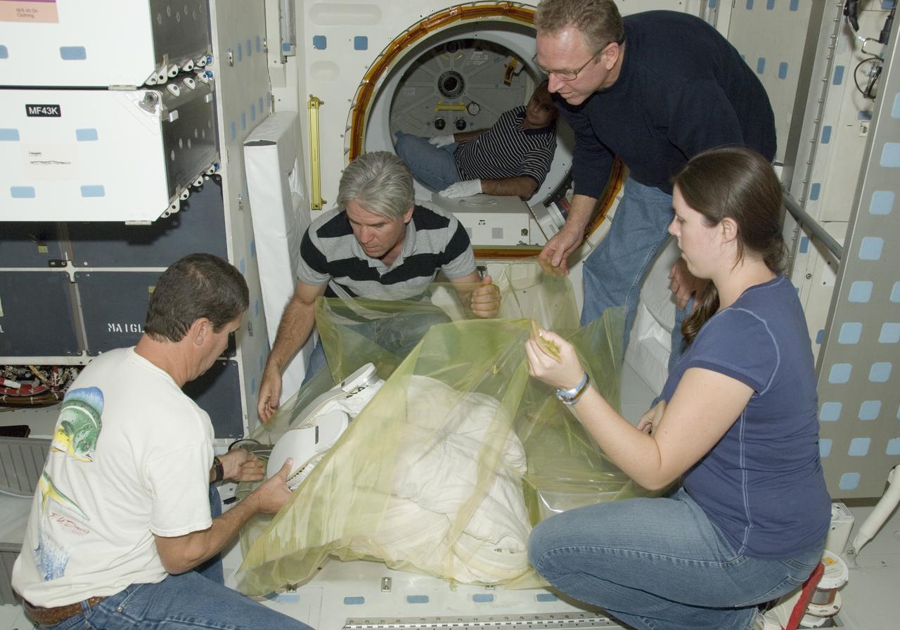
United Space Alliance technicians wrap the lower portion of an Extravehicular Mobility Unit (EMU) spacesuit prior to removal from Space Shuttle Endeavour.
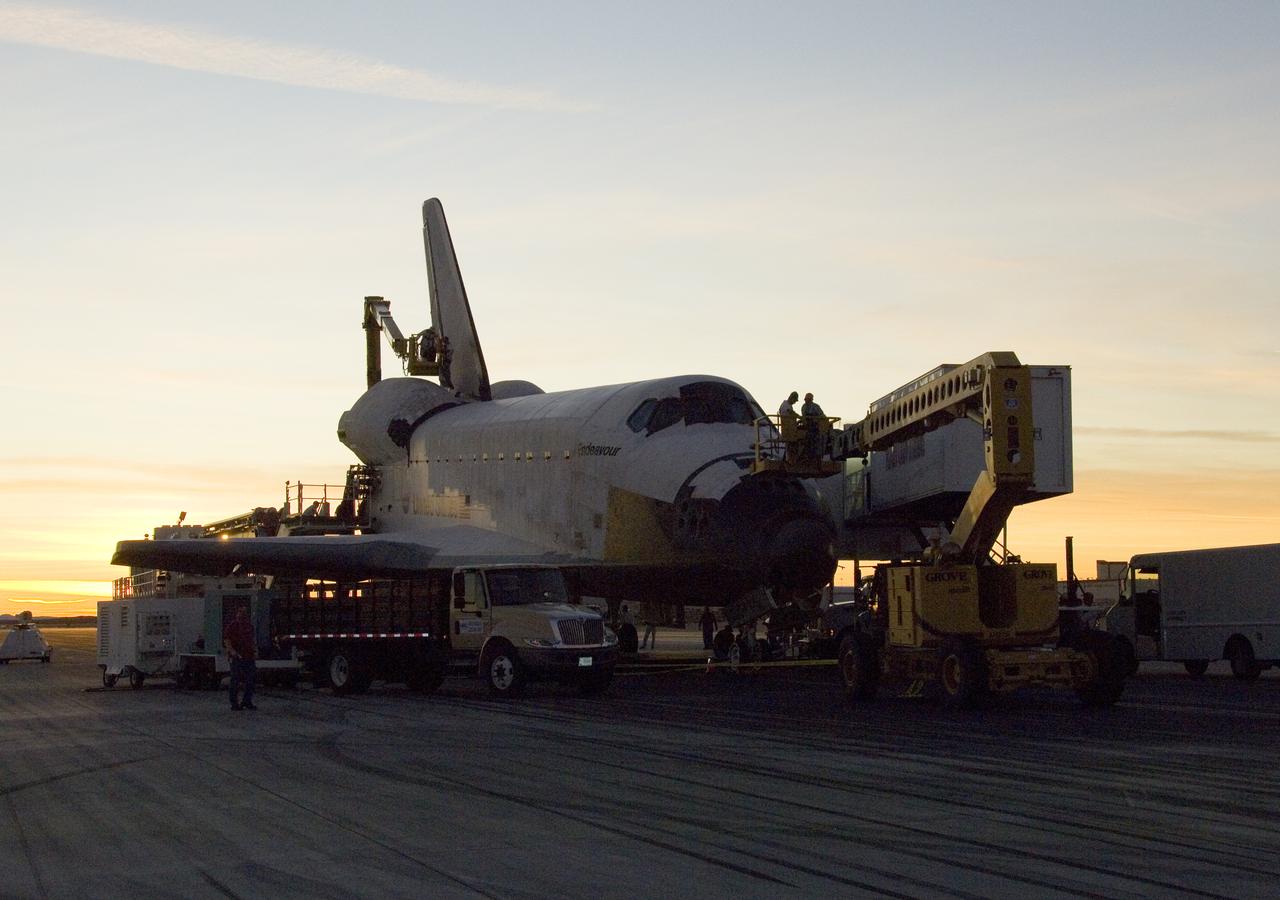
As the sun sets over the high desert, NASA technicians on mobile high-lifts prepare the shuttle Endeavour for towing off the Edwards Air Force Base runway.
KENNEDY SPACE CENTER, FLA. - A technician with United Space Alliance checks wiring in the mid-body and flight deck of orbiter Atlantis as part of routine maintenance.
Technicians carefully maneuver a spreader bar into place before removing the telescope aperture assembly from NASA's SOFIA infrared observatory Boeing 747SP.
United Space Alliance flight systems technicians Troy Mann, Mark Shimei and Jim Smodell remove the lower portion of an Extravehicular Mobility Unit (EMU) suit from Endeavour's airlock.
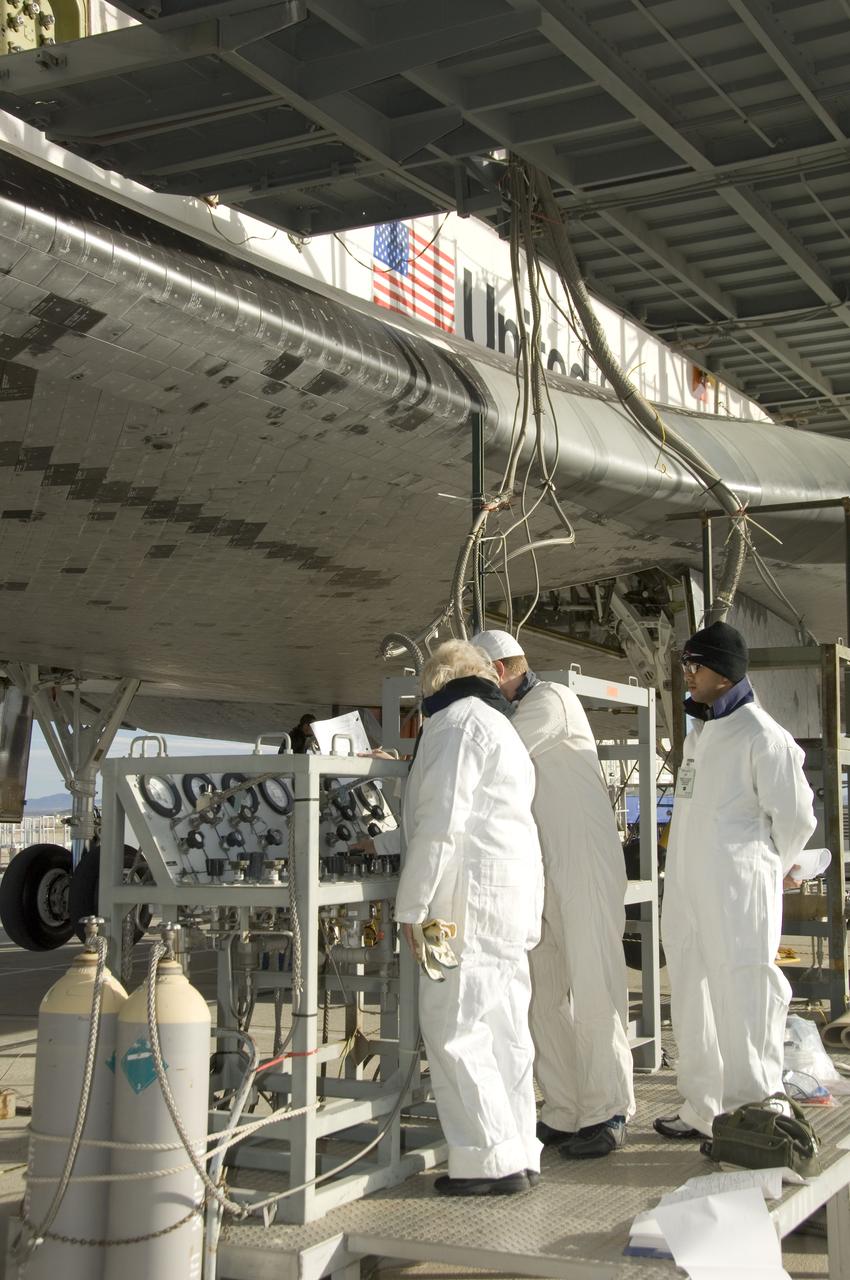
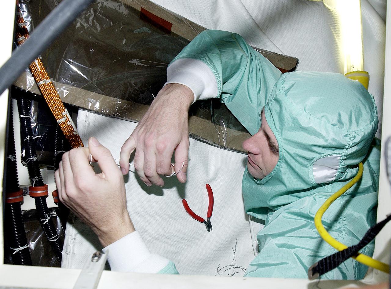
Technicians in protective coveralls check pressures of fluid systems during deservicing operations on Space Shuttle Endeavour after its landing at Edwards Air Force Base Nov. 30, 2008.
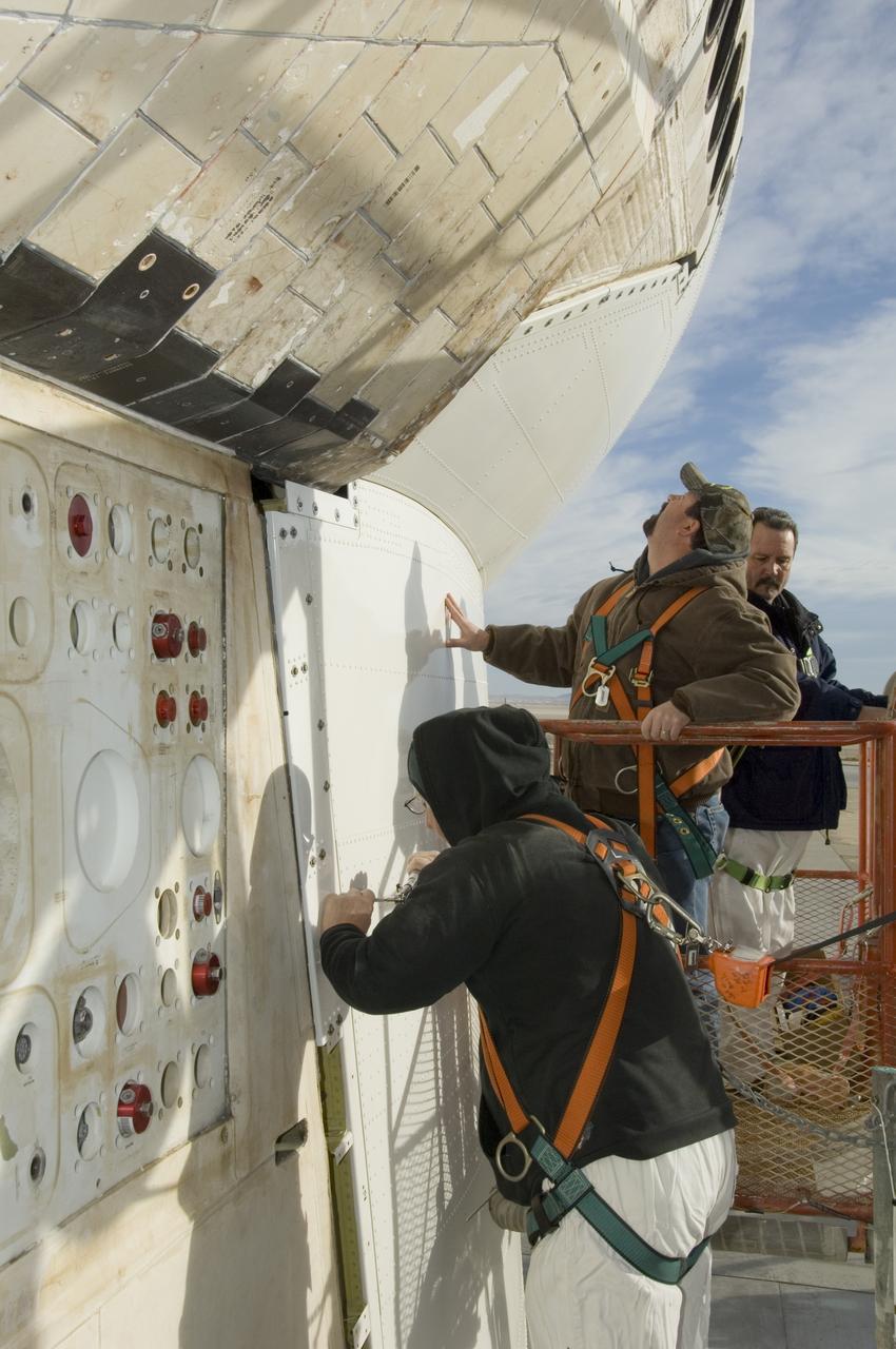
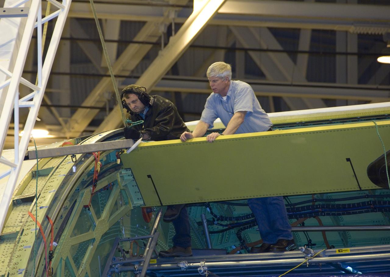
Technicians fasten down the flanges of the aerodynamic tail cone after installation on NASA's Space Shuttle Endeavour prior to its ferry flight from NASA's Dryden Flight Research Center to NASA's Kennedy Space Center in Florida.
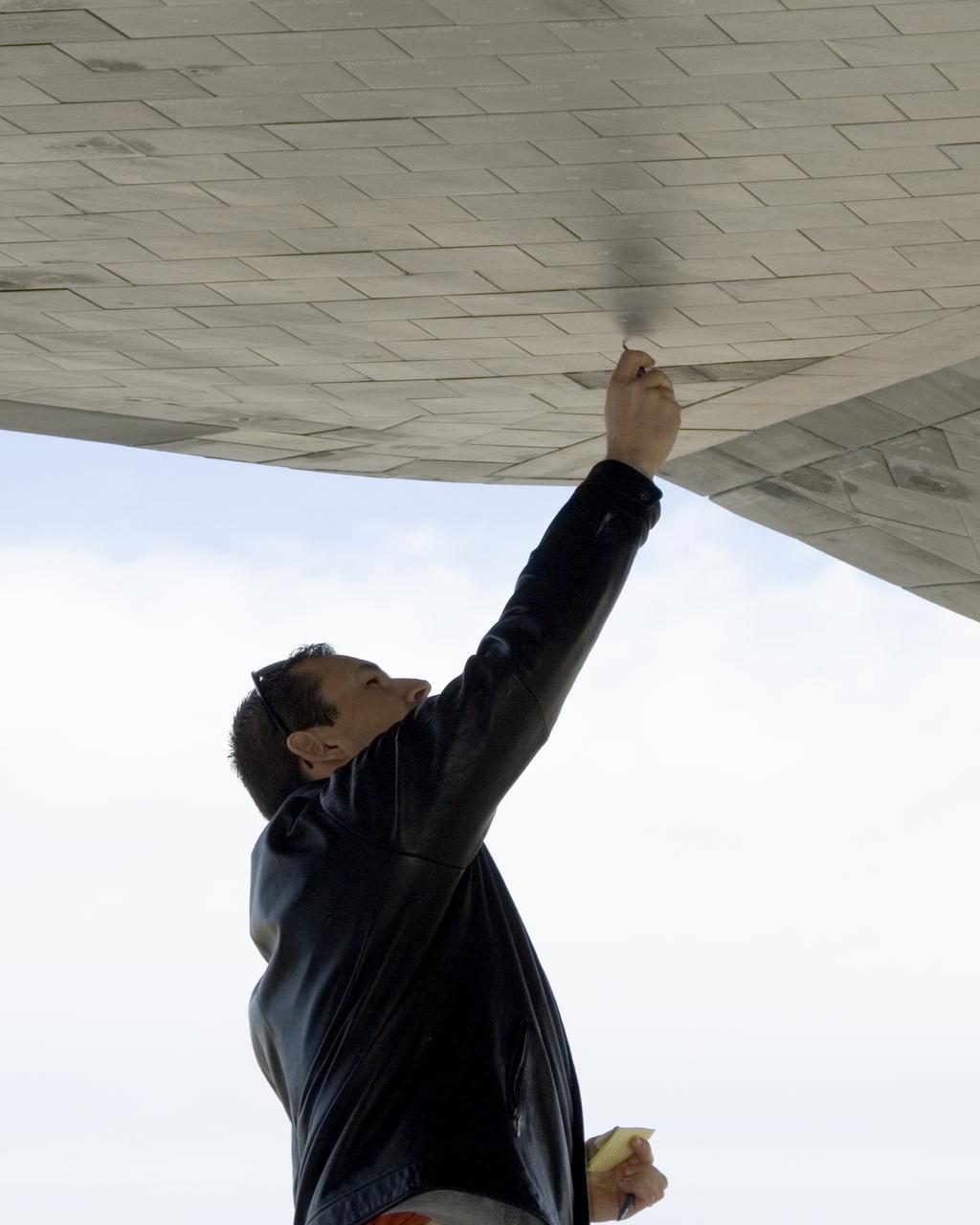
A United Space Alliance technician carefully checks the thermal tiles on the underside of Space Shuttle Endeavour for nicks and dings following its landing at Edwards Air Force Base to conclude mission STS-126.

NASA Dryden aircraft and avionics technicians (from left) Bryan Hookland, Art Cope, Herman Rijfkogel and Jonathan Richards install the nose cone on a Phoenix missile prior to a fit check on the center's F-15B research aircraft.
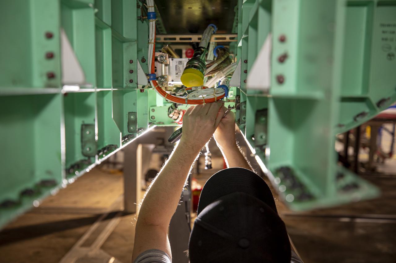
A technician is shown working on the underside of the X-59. The aircraft, under construction at Lockheed Martin Skunk Works in Palmdale, California, will fly to demonstrate the ability to fly supersonic while reducing the loud sonic boom to a quiet sonic thump. Lockheed Martin Photography By Garry Tice 1011 Lockheed Way, Palmdale, Ca. 93599 Event: SEG 450 Mid Bay - PDS Fit Check Date: 5/03/2021
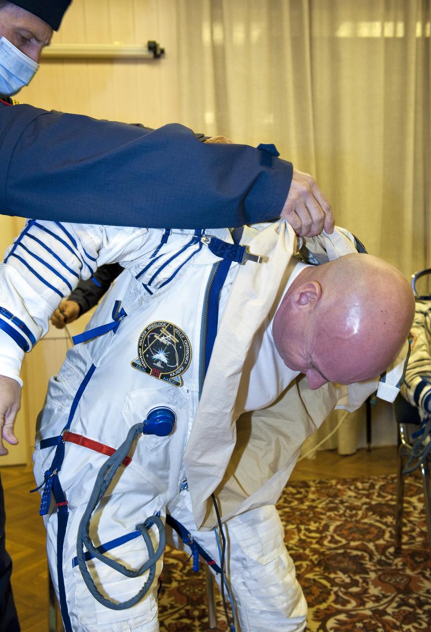
Expedition 25 NASA Flight Engineer Scott Kelly of the U.S. has his Russian Sokol suit prepared for launch by a technician at the Baikonur Cosmodrome in Kazakhstan, Friday, Oct. 8, 2010. Kelly and fellow Expedition 25 crew members Soyuz Commander Alexander Kaleri and Flight Engineer Oleg Skripochka launched in their Soyuz TMA-01M at 5:10 a.m. Friday morning. (Photo Credit: NASA/Carla Cioffi)