This archival photo shows the encapsulation of the Voyager Development Test Model at NASA's Kennedy Space Center's Eastern Test Range. The picture was taken on October 8, 1976.  https://photojournal.jpl.nasa.gov/catalog/PIA21730
Voyager Development Test Model
This archival photo shows the Voyager proof test model, which did not fly in space, in the 25-foot space simulator chamber at NASA's Jet Propulsion Laboratory on December 3, 1976.  https://photojournal.jpl.nasa.gov/catalog/PIA21735
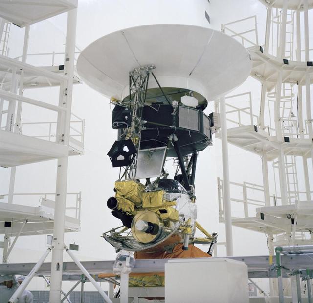
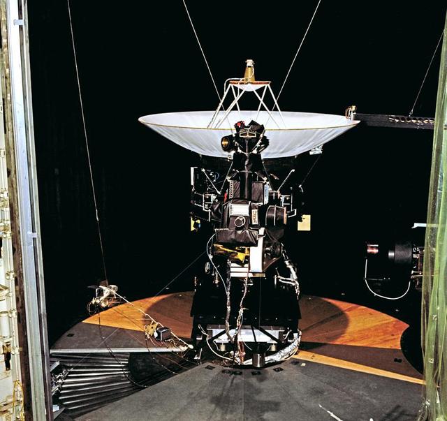
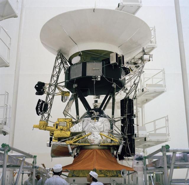
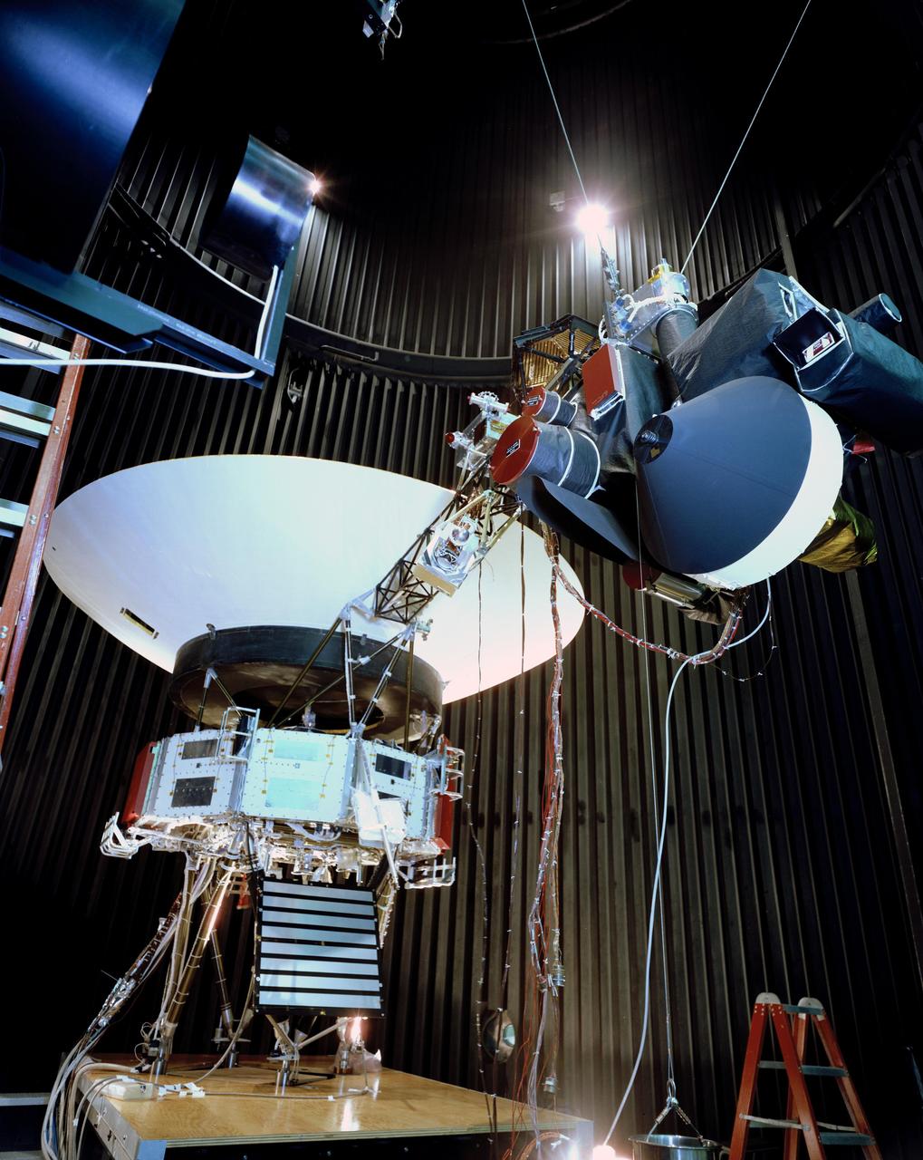
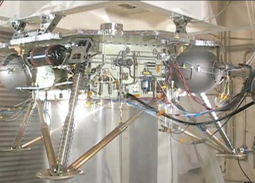
Voyager Test Model Configuration
This archival photo shows the Voyager Proof Test Model undergoing a mechanical preparation and weight center of gravity test at NASA's Jet Propulsion Laboratory, Pasadena, California, on January 12, 1977. The stack of three white cylinders seen near center is a stand-in for the spacecraft's power generators (called RTGs). Above that, a silvery canister holds the spacecraft's magnetometer in its stowed configuration.  https://photojournal.jpl.nasa.gov/catalog/PIA21477
Voyager Proof Test Model
This archival photo shows the Voyager Proof Test Model (in the foreground right of center) undergoing a mechanical preparation and weight center of gravity test at NASA's Jet Propulsion Laboratory, Pasadena, California, on January 12, 1977.   https://photojournal.jpl.nasa.gov/catalog/PIA21476
Voyager Proof Test Model and Cleanroom
L59 RC Kit Model/Learn to fly test technique and modeling development Persons in the picture: Left to right: Jay Brandon, Sue Grafton, Wes O'Neal, Mark Croom, Earl Harris, and Eric Viken
L-59 RC Kit Model/ Learn to Fly Test
L59 RC Kit Model/Learn to fly test technique and modeling development Persons in the picture: Left to right: Jay Brandon, Sue Grafton, Wes O'Neal, Mark Croom, Earl Harris, and Eric Viken
L-59 RC Kit Model/ Learn to Fly Test
L59 RC Kit Model/Learn to fly test technique and modeling development Persons in the picture: Left to right: Jay Brandon, Sue Grafton, Wes O'Neal, Mark Croom, Earl Harris, and Eric Viken
L-59 RC Kit Model/ Learn to Fly Test
The unveiling of the B-2 Test Stand model for the SLS management team and employees in building 4220. Taking part was John Honeycutt and Julie Bassler.
Unveiling of B-2 Test Stand Model
The unveiling of the B-2 Test Stand model for the SLS management team and employees in building 4220. Taking part was John Honeycutt and Julie Bassler.
Unveiling of B-2 Test Stand Model
The unveiling of the B-2 Test Stand model for the SLS management team and employees in building 4220. Taking part was John Honeycutt and Julie Bassler.
Unveiling of B-2 Test Stand Model
This archival photo shows the Voyager proof test model, which did not fly in space, in the 25-foot space simulator chamber at NASA's Jet Propulsion Laboratory, Pasadena, California.  https://photojournal.jpl.nasa.gov/catalog/PIA21726
Voyager 2 Flight Hardware
This archival photo shows the encapsulation of the Voyager Development Test Model at NASA's Kennedy Space Center's Eastern Test Range. The picture was taken on October 8, 1976.  https://photojournal.jpl.nasa.gov/catalog/PIA21731
Voyager Development Test Model
Sonic Boom test model and measuring probe rake with Christine Darden
Sonic Boom Test Model with Christine Darden
(03/12/1976) 1/50 scale model of the 80x120 foot wind tunnel model (NFAC) in the test section of the 40x80 wind tunnel.  Model viewed from the west, mounted on a rotating ground board designed for this test. Ramp leading to ground board includes a generic building placed in front of the 80x120 inlet.
1/50 Scale Model Of The 80x120 Foot Wind Tunnel Model (NFAC) In The Test Section Of The 40x80 Wind Tunnel.
Sonic Boom test model and measuring probe rake with Christine Darden
Sonic Boom Test Model with Christine Darden
(03/12/1976) Overhead view of 1/50 scale model of the 80x120 foot wind tunnel model (NFAC) in the test section of the 40x80 wind tunnel at NASA Ames. Model mounted on a rotating ground board designed for this test.
1/50 Scale Model Of The 80X120 Foot Wind Tunnel Model (NFAC) In The Test Section Of The 40X80 Wind Tunnel At Nasa Ames.
(03/12/1976) 1/50 scale model of the 80x120 foot wind tunnel model (NFAC) in the test section of the 40x80 foot wind tunnel. Model mounted on a rotating ground board designed for this test, viewed from the west, oriented for North wind.
A76-0634. 1/50 Scale Model Of The 80X120 Foot Wind Tunnel Model (Nfac) In The Test Section Of The 40X80 Foot Wind Tunnel.
The engineering test model for the radar system that will be used during the next landing on Mars is shown here mounted onto a helicopter nose gimbal during a May 12, 2010, test at NASA Dryden Flight Research Center, Edwards, Calif.
Test Model of Mars Landing Radar
This archival photo shows the Voyager proof test model, which did not fly in space, in the 25-foot space simulator chamber at NASA's Jet Propulsion Laboratory, Pasadena, California, on December 3, 1976. The spacecraft is seen here with its scan platform, which holds several of its science instruments, in the deployed position.  https://photojournal.jpl.nasa.gov/catalog/PIA21734
Voyager Test Model Configuration
THIS IS A TEST OF THE 1ST STAGE RE-ENTRY VEHICLE. HEAT TESTING OF A 3% MODEL TO SUPPORT THE ARES/ CLV FIRST STAGE RE-ENTRY. THIS TEST OCCURRED AT ARNOLD AIR FORCE BASE, TENNESSEE.  THIS TESTING SUPPORTS THE DEVELOPMENT OF THE CONSTELLATION/ARES PROJECT.   THIS IMAGE IS EXTRACTED FROM A HIGH DEFINITION VIDEO FILE AND IS THE HIGHEST RESOLUTION AVAILABLE.
Advanced Concept
Sonic Boom test model and measuring probe rake with Christine Darden
Sonic Boom Test Model with Christine Darden
Frank Pena and Benjamin Park watch as data streams in from tests on a 6-foot model of the Transonic Truss-Braced Wing at NASA’s Armstrong Flight Research Center, in Edwards, California.
NASA Armstrong Tests Model Wing
A model Sample Recovery Helicopter drives and positions itself over a sample tube during a test in the Mars Yard at NASA's Jet Propulsion Laboratory in Southern California.  Two Sample Recovery Helicopters are slated to fly to Mars as part of the Mars Sample Return campaign. NASA is developing the Sample Recovery Helicopters to serve as backups to the agency's Perseverance rover in transporting sample tubes to the Sample Retrieval Lander.  These helicopters are follow-ons to NASA's Ingenuity Mars Helicopter, which arrived at the Red Planet in the belly of Perseverance in February 2021. The Sample Recovery Helicopters have wheels instead of feet, as well as a small manipulator arm with a two-fingered gripper capable of carrying precious sample tubes.  Testing of the Sample Recovery Helicopters is ongoing. The testbed was made by AeroVironment Inc.  Movie available at https://photojournal.jpl.nasa.gov/catalog/PIA25320
Sample Recovery Helicopter Model Gets a Test
LSAWT\Twin Jet Test with HWB Model\JEDA Measurements  Low Speed Aeroacoustic Wind Tunnel\Twin Jet Model System \Hybrid Wing Model Installed\ Measurement Technique: Jet Directional Array (JEDA)
LSAWT\Twin Jet Test with HWB Model\JEDA Measurements
LSAWT\Twin Jet Test with HWB Model\JEDA Measurements  Low Speed Aeroacoustic Wind Tunnel\Twin Jet Model System \Hybrid Wing Model Installed\ Measurement Technique: Jet Directional Array (JEDA)
LSAWT\Twin Jet Test with HWB Model\JEDA Measurements
LSAWT\Twin Jet Test with HWB Model\JEDA Measurements  Low Speed Aeroacoustic Wind Tunnel\Twin Jet Model System \Hybrid Wing Model Installed\ Measurement Technique: Jet Directional Array (JEDA)
LSAWT\Twin Jet Test with HWB Model\JEDA Measurements
LSAWT\Twin Jet Test with HWB Model\JEDA Measurements  Low Speed Aeroacoustic Wind Tunnel\Twin Jet Model System \Hybrid Wing Model Installed\ Measurement Technique: Jet Directional Array (JEDA)
LSAWT\Twin Jet Test with HWB Model\JEDA Measurements
John Honeycutt and Mark White compare model of SLS test stand with actual test stand
John Honeycutt and Mark White with SLS test stand and model
(11/12/1971) 3/4 Scale swept augmentor wing Quest model being installed into the test section of the ames 40 x 80 foot wind tunnel, overhead doors open.
A71-8290. Swept Augmentor Wing Model Being Installed Into The Test Section Of The Ames 40 X 80 Foot Wind Tunnel.
APOLLO STABILITY TEST IN THE 8X6 FOOT WIND TUNNEL - MODEL IS SHOWN WITH MODULE TOWER AND CANARDS
APOLLO STABILITY TEST IN THE 8X6 FOOT WIND TUNNEL - MODEL IS SHO
Apollo Contour Engine Model being tested in the NASA Lewis Research Center, Propulsion Systems Laboratory, PSL
Apollo Contour Engine Model being tested in the NASA Lewis Resea
Apollo Contour Engine Model being tested in the NASA Lewis Research Center, Propulsion Systems Laboratory, PSL
Apollo Contour Engine Model being tested in the NASA Lewis Resea
NASA’s Sustainable Flight Demonstrator project concluded wind tunnel testing in the fall of 2024. Tests on a Boeing-built X-66 model were completed at NASA’s Ames Research Center in California’s Silicon Valley in the 11-Foot Transonic Unitary Plan Facility. The model underwent tests representing expected flight conditions to obtain engineering information to influence design of the wing and provide data for flight simulators.
Wind Over Its Wing: NASA’s X-66 Model Tests Airflow
Test Setup For Model Landing Investigation of a Winged Space Vehicle  Image used in NASA Document TN-D-1496  1960-L-04633.01 is Figure 9a for NASA Document L-2064 Photograph of model on launcher and landing on runway.
Test Setup For Model Landing Investigation of a Winged Space Vehicle
Test Setup For Model Landing Investigation of a Winged Space Vehicle  Image used in NASA Document TN-D-1496  1960-L-04633.01 is Figure 9a for NASA Document L-2064 Photograph of model on launcher and landing on runway.
Test Setup For Model Landing Investigation of a Winged Space Vehicle
Test Setup For Model Landing Investigation of a Winged Space Vehicle  Image used in NASA Document TN-D-1496  1960-L-04633.01 is Figure 9a for NASA Document L-2064 Photograph of model on launcher and landing on runway.
Test Setup For Model Landing Investigation of a Winged Space Vehicle
Project 8019 Vertical Ares Scale Model Acoustic Test (ASMAT) Ignition Over Pressure (IOP) Test #3,  11/18/2010 P8019_VERT 03-016
1001876
Shown is a wind tunnel test of the Ares model for force/moment testing in support of the Ares/Clv integrated vehicle at Langley Research Center, Virginia.  The image is extracted from a high definition video file and is the highest resolution available.
Advanced Concept
Project 8019 Vertical Ares Scale Model Acoustic Test (ASMAT) Ignition Over Pressure (IOP) Test #3,  11/18/2010 P8019_VERT 03-078
1001875
Here you see the X-59 scaled model inside the JAXA supersonic wind tunnel during critical tests related to sound predictions.
X-59 Model Tested in Japanese Supersonic Wind Tunnel
Lead researcher Tadas Bartkus poses after a run of his test with significant ice build-up on the Simulated Inter-compressor Duct Research Model (SIDRM) at the Icing Research Tunnel. Photo Credit: (NASA/Jordan Salkin)
Tadas Bartkus posing with SIDRM Ice Build-up
NASA's Langley Research Center in Hampton, Va., recently conducted hypersonic testing of Dream Chaser models for SNC as part of the agency's Commercial Crew Program in order to obtain necessary data for the material selection and design of the TPS
Dream Chaser Model Being Tested at Langley Research Center (LaRC
An AH-64 (Apache) Longbow fire control full size radar photographed during icing tests in the Icing Research wind tunnel.  Built at the end of World War II, the Icing Research Tunnel is the oldest and largest refrigerated icing wind tunnel in the world. It can produce winds that travel up to 395 miles per hour and reach temperatures as low as -30 degrees Fahrenheit. The facility simulates ice formation during flight by spraying a cloud of super-cooled water droplets onto an aircraft component or model.
LONG BOW MODEL DURING ICING TEST
0.4% Scale (SLS) Space Launch System Model Test In NASA LaRC Unitary Plan Wind Tunnel
0.4% Scale (SLS) Space Launch System Model Test In NASA LaRC Uni
0.4% Scale (SLS) Space Launch System Model Test In NASA LaRC Unitary Plan Wind Tunnel
0.4% Scale (SLS) Space Launch System Model Test In NASA LaRC Uni
0.4% Scale (SLS) Space Launch System Model Test In NASA LaRC Unitary Plan Wind Tunnel
0.4% Scale (SLS) Space Launch System Model Test In NASA LaRC Uni
Scale-model of final X-15 configuration, mounted for testing in the Langley 11-Inch Hypersonic Tunnel.
0.4% Scale (SLS) Space Launch System Model Test In NASA LaRC Unitary Plan Wind Tunnel
0.4% Scale (SLS) Space Launch System Model Test In NASA LaRC Uni
0.4% Scale (SLS) Space Launch System Model Test In NASA LaRC Unitary Plan Wind Tunnel
0.4% Scale (SLS) Space Launch System Model Test In NASA LaRC Uni
0.4% Scale (SLS) Space Launch System Model Test In NASA LaRC Unitary Plan Wind Tunnel
0.4% Scale (SLS) Space Launch System Model Test In NASA LaRC Uni
North American X-15 Model being readied for tests in Langley Unitary Plan
Orion Capsule and Launch Abort System (LAS) installed in the NASA Glenn 8x6 Supersonic Wind Tunnel for testing.  This test is an Aero Acoustic test of the LAS.  Pictured is the calibration of the model's angle of attack
Orion Capsule and Launch Abort System (LAS) installed in the NASA Glenn 8x6 Supersonic Wind Tunnel for testing. This test is an Aero Acoustic test of the LAS. Pictured is the calibration of the model's angle of attack
Scarecrow, a mobility-testing model for NASA Mars Science Laboratory, easily traverses large rocks in the Mars Yard testing area at NASA Jet Propulsion Laboratory.
Scarecrow Climbs Rocks
NASA’s Sustainable Flight Demonstrator project concluded wind tunnel testing in the fall of 2024. Tests on a Boeing-built X-66 model were completed at NASA’s Ames Research Center in Silicon Valley, California, in the 11-Foot Transonic Unitary Plan Facility. Pressure points, which are drilled holes with data sensors attached, are installed along the edge of the wing and allow engineers to understand the characteristics of airflow and will influence the final design of the wing.
Wind Over Its Wing: NASA’s X-66 Model Tests Airflow
Common Research Model, CRM Full Chord and Midspan Test in the Icing Research Tunnel, IRT
CRM Full Chord and Midspan Test Documentation Photos Icing Research Tunnel
Sonic boom test models
Sonic Boom Test
Engineering technician Jeff Howell mounts conventional strain gauges to the Mock Truss-Braced Wing 10-foot model at NASA’s Armstrong Flight Research Center in Edwards, California. The conventional system data will be compared the Fiber Optic Sensing System developed at the center on the same wing to see how well the testing methods match.
NASA Prepares for Mock Truss-Braced Wing Tests
This video shows the propulsion system on an engineering model of NASA Phoenix Mars Lander being successfully tested.
Water Hammer Test
Engineers prepare a small rover – part of NASA's CADRE (Cooperative Autonomous Distributed Robotic Exploration) technology demonstration that's headed to the Moon – for testing in the thermal vacuum chamber behind them at the agency's Jet Propulsion Laboratory in Southern California in October 2023.  Slated to arrive at the Moon in 2024 as part of NASA's CLPS (Commercial Lunar Payload Services) initiative, CADRE is designed to demonstrate that multiple robots can cooperate and explore together autonomously – without direct input from human mission controllers.  A trio of the miniature solar-powered rovers, each about the size of a carry-on suitcase, will explore the Moon as a team, communicating via radio with each other and a base station aboard a lunar lander. By taking simultaneous measurements from multiple locations, CADRE will also demonstrate how multirobot missions can record data impossible for a single robot to achieve – a tantalizing prospect for future missions.  The rover being tested is the first flight model to be completed. Thermal vacuum testing simulates the harsh environment the rovers will face on the journey to the Moon and on the lunar surface: All the air is pumped out of the chamber and the temperature is cycled to high and low extremes.  https://photojournal.jpl.nasa.gov/catalog/PIA25670
CADRE Team Preps Flight Model for Thermal Testing
3/4 front view from below of Delta wing Model with Nose Inlet in Ames 40x80 foot wind tunnel.
Delta Wing Test Model in Ames 40x80 Foot Wind Tunnel.
NASA GLENN/NASA LANGLEY LOADS COMPARISON TEST WITH 6 COMPONENT FORCE/MOMENT BALANCE AND 1.7% HIGH SPEED RESEARCH MODEL 5.
A test model of the RIMFAX instrument — aboard the trailer behind the snow mobile — undergoes field testing in Svalbard, Norway.  The first ground-penetrating radar set on the surface of Mars, RIMFAX can provide a highly detailed view of subsurface structures down to at least 30 feet (10 meters) underground. In doing so, the instrument will reveal hidden layers of geology and help find clues to past environments on Mars, especially those with conditions necessary for supporting life.  https://photojournal.jpl.nasa.gov/catalog/PIA24048
Testing RIMFAX for NASA's Perseverance Rover
ForeSight, a fully functional, full-size model of NASA's InSight lander, practices deploying a model of the lander's Wind and Thermal Shield while engineers Phil Bailey (left) and Jaime Singer (center) look on. The Wind and Thermal Shield protects InSight's seismometer. This testing was done at NASA's Jet Propulsion Laboratory in Pasadena, California.  Bailey is wearing sunglasses to block the bright yellow lights in the test space, which mimic sunlight as it appears on Mars.  https://photojournal.jpl.nasa.gov/catalog/PIA22955
Setting the Wind and Thermal Shield
ForeSight, a fully functional, full-size model of NASA's InSight lander, grasps a model of the lander's Wind and Thermal Shield while engineer Maggie Williams looks on. This testing was done at NASA's Jet Propulsion Laboratory in Pasadena, California.  Williams is wearing sunglasses to block the bright yellow lights in the test space, which mimic sunlight as it appears on Mars.  https://photojournal.jpl.nasa.gov/catalog/PIA22954
ForeSight's Grapple
This image, taken April 9, 2010, shows the test radar affixed to a gimbal mounting at the front of a helicopter, carrying an engineering test model of the landing radar for NASA Mars Science Laboratory.
Radar Testing for Mars Science Labotatory
This test for the radar system to be used during the August 2012 descent and landing of NASA Mars rover Curiosity mounted an engineering test model of the radar system onto the nose of a helicopter.
Test at NASA Dryden of Radar System for Next Mars Landing
In advance of a testing flight at NASA Dryden Flight Research Center, members of the test team prepare the engineering model of the Mars Science Laboratory descent radar on the nose gimbal of a helicopter. The yellow disks are the radar antennae.
Preparing for a Mars Radar Test
Onlookers watch as Scarecrow, a mobility-testing model for NASA Mars Science Laboratory, easily conquers boulders in the Mars Yard testing area at NASA Jet Propulsion Laboratory.
Shutterbugs Shoot Scarecrow
A one-twentieth scale model of the X-15  originally suspended beneath the wing of a B-52 is observed by a scientist of the National Aeronautics and Space Administration (NASA) as it leaves the bomber model in tests to determine the release characteristics and drop motion of the research airplane. Caption:  The aerodynamics of air launching the North American X-15 being investigated in the 300MPH Low Speed 7x10 Tunnel, about 1957.  Photograph published in Engineer in Charge: A History of the Langley Aeronautical Laboratory, 1917-1958 by James R. Hansen. Page 366. Photograph also published in Sixty Years of Aeronautical Research 1917-1977 By David A. Anderton. A NASA publication. Page 49.
North American X-15 model tested in 300MPH Low Speed 7x10 Tunnel
NASA Glenn/NASA Langley, Loads Comparison Test With 6 Component Force/Moment Balance and 1.7% High Speed Research, HSR Model 5. In the Glenn Research Center 10x10 Foot Supersonic Wind Tunnel, SWT
NASA Glenn/NASA Langley Loads Comparison Test with 6 Component Force/Moment Balance and 1.7% High Speed Research, HSR Model 5
NASA GLENN/NASA LANGLEY LOADS COMPARISON TEST WITH 6 COMPONENT FORCE/MOMENT BALANCE AND 1.7% HIGH SPEED RESEARCH MODEL 5. in the 10x10 super sonic wind tunnel
NASA GLENN/NASA LANGLEY LOADS COMPARISON TEST WITH 6 COMPONENT FORCE/MOMENT BALANCE AND 1.7% HIGH SPEED RESEARCH MODEL 5.
This picture shows a model of NASA Mars Exploration Rover Spirit being tested for performance on five wheels at NASA Jet Propulsion Laboratory.
Testing Spirit on Five Wheels
An engineering model for NASA Mars Science Laboratory makes its way up a hill in the Mars Yard testing area at NASA Jet Propulsion Laboratory.
Scarecrow Descends Hill
The Orion aerosciences team has performed more than 30 tests across the United States in support of the program, investigating the heating of the spacecraft during re-entry into Earth’s atmosphere. Testing recently concluded at NASA’s Langley Research Center in Hampton, Virginia with a 6-inch Orion heat shield model in the 20-inch Mach 6 wind tunnel, shown here on Feb. 4, 2019. The team includes engineers at Langley, NASA’s Johnson Space Center in Houston, Texas, and NASA’s Ames Research Center in Silicon Valley.
Small Model, Big Science: Testing a 6-inch Orion Heat Shield Mod
Engineer Marleen Sundgaard watches as a test version of NASA's Mars InSight lander grasps a model of the spacecraft's seismometer. This work was done at NASA's Jet Propulsion Laboratory in Pasadena, California.  https://photojournal.jpl.nasa.gov/catalog/PIA22952
Inspecting Instrument Deployment
This engineering model of Mars Oxygen In-Situ Resource Utilization Experiment (MOXIE) instrument is about to undergo vibration testing in a lab at the Jet Propulsion Laboratory in Pasadena, California. Vibration tests demonstrate the ability of instruments to survive the extreme conditions of both a rocket launch from Earth and a landing on Mars.  https://photojournal.jpl.nasa.gov/catalog/PIA24202
MOXIE Shakes it UP
Tilt wing propeller model. 3/4 front view. 4 prop tilt wing nose down variable struts on ground board.  Leo Holl, NASA Ames Engineer.
Tilt Wing Propeller Model Tested in the Ames 40x80 Foot Wind Tunnel.
Investigation of a tilt-wing/propeller model with blowing flaps. 3/4 front view, tilt wing model, wing position = 0deg. C-123 fuselage, conventional struts, 4 props
Testing Tilt Wing Propeller Model in Ames 40x80 Foot Wind Tunnel.
Members of NASA's Mars Helicopter team prepare the flight model (vehicle going to Mars) for a test in the Space Simulator, a 25-foot-wide (7.62-meter-wide) vacuum chamber at NASA's Jet Propulsion Laboratory in Pasadena, California. The image was taken on Jan. 18, 2019.  https://photojournal.jpl.nasa.gov/catalog/PIA23156
Mars Helicopter Team Prepares for Test
In May and June, NASA researchers tested a 7-foot wing model in the 14-by-22-Foot Subsonic Wind Tunnel at NASA’s Langley Research Center in Hampton, Virginia. The team collected data on critical propeller-wing interactions over the course of several weeks
NASA Tests Advanced Air Mobility Aircraft Wing in Langley Wind Tunnel
This test using an engineering model of the InSight lander here on Earth shows how the spacecraft on Mars will use its robotic arm to press on a digging device, called the "mole."  https://photojournal.jpl.nasa.gov/catalog/PIA23619
Robotic Arm Pushes on a Model of the Mole
This image, taken April 9, 2010, shows a helicopter carrying an engineering test model of the landing radar for NASA Mars Science Laboratory over a patch of desert with abundant California poppies.
Testing of Mars Landing Radar near Lancaster, Calif.
Multiple exposure of a test with a prototype Lunar Excursion Module. This test was one of many conducted at Langley of the structural dynamics of lunar landing.
Lunar Excursion Model Testing
A NASA Dryden Flight Research Center F/A-18 852 aircraft performs a roll during June 2011 flight tests of a Mars landing radar. A test model of the landing radar for NASA Mars Science Laboratory mission is inside a pod under the aircraft left wing.
Flight Testing the Landing Radar for Mars Science Laboratory
This image shows a test using an engineering model of the soil scoop for NASA Mars rover Curiosity. The scoop dips to about 1.4 inches 3.5 centimeters deep. This test took place at NASA Jet Propulsion Laboratory, Pasadena , Calif., in 2011.
Test Scooping for Mars Rover Curiosity
A NASA Dryden Flight Research Center F/A-18 852 aircraft makes a 40-degree dive during June 2011 flight tests of a Mars landing radar. A test model of the landing radar for NASA Mars Science Laboratory mission is inside a pod under the left wing.
Airborne Testing for Mars Landing Radar by Dryden F/A-18