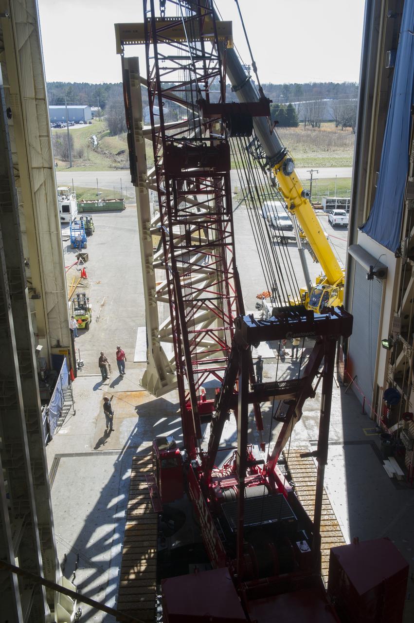
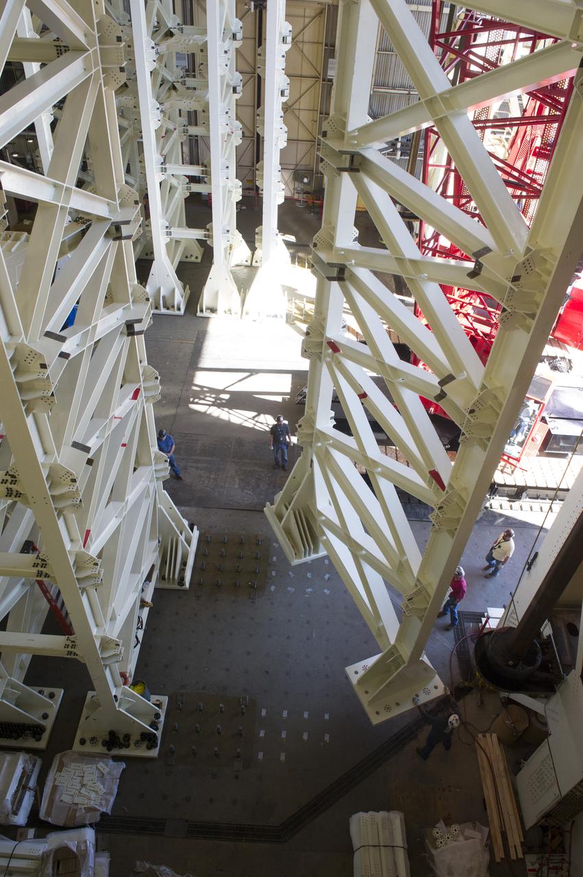
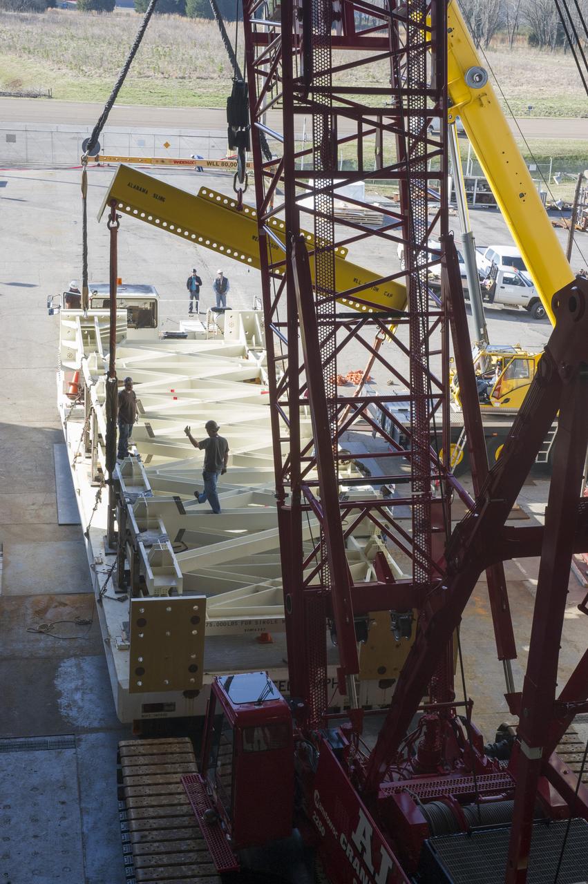
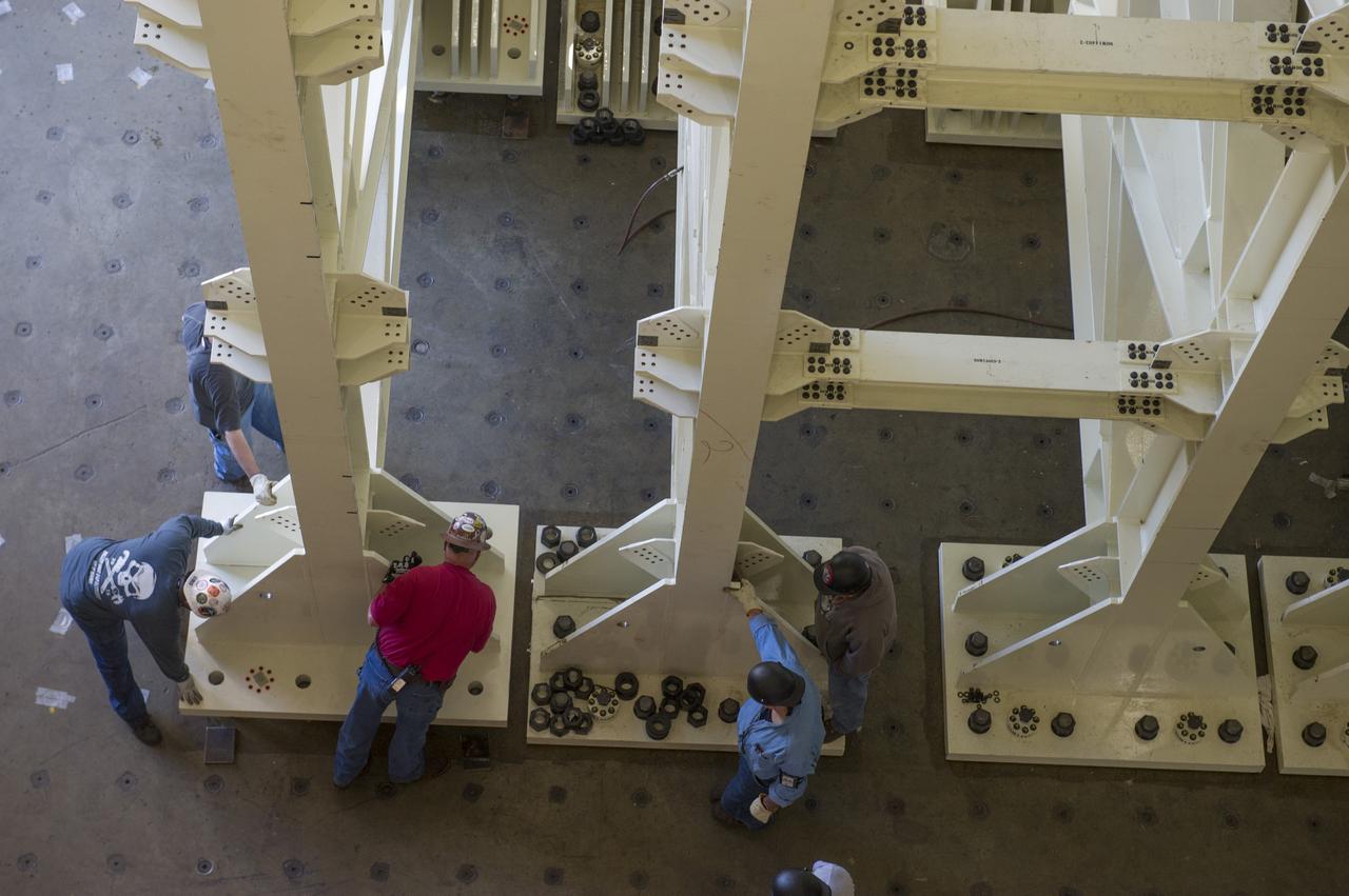
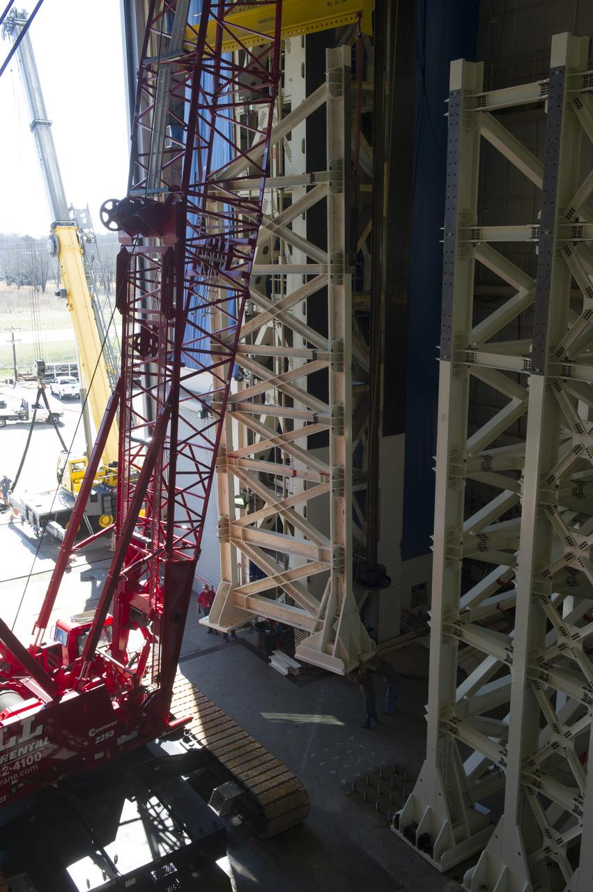
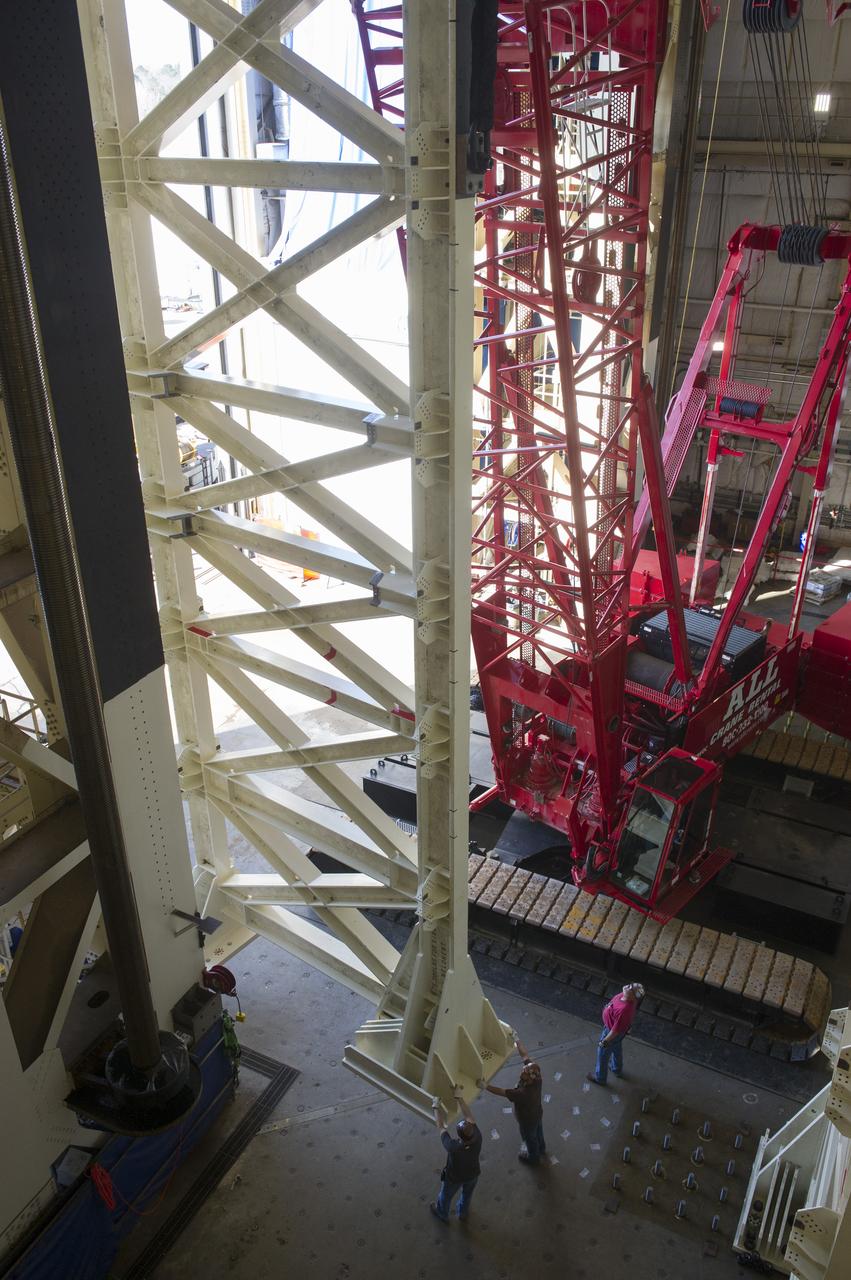
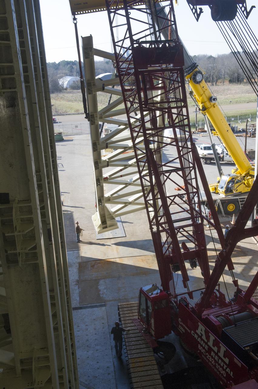
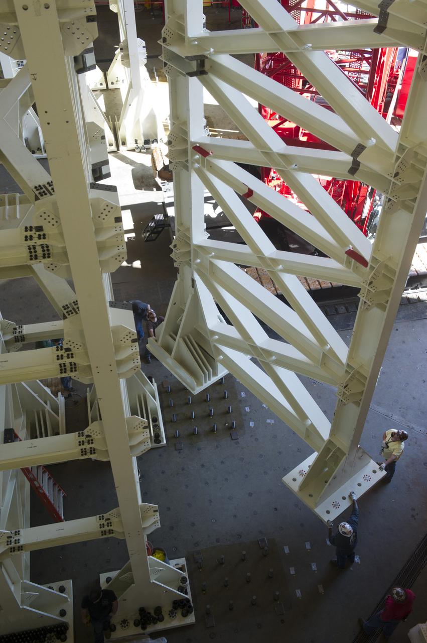
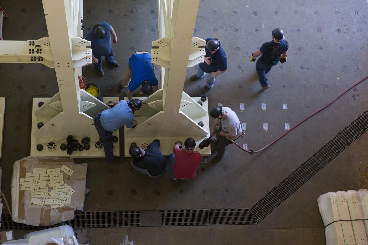
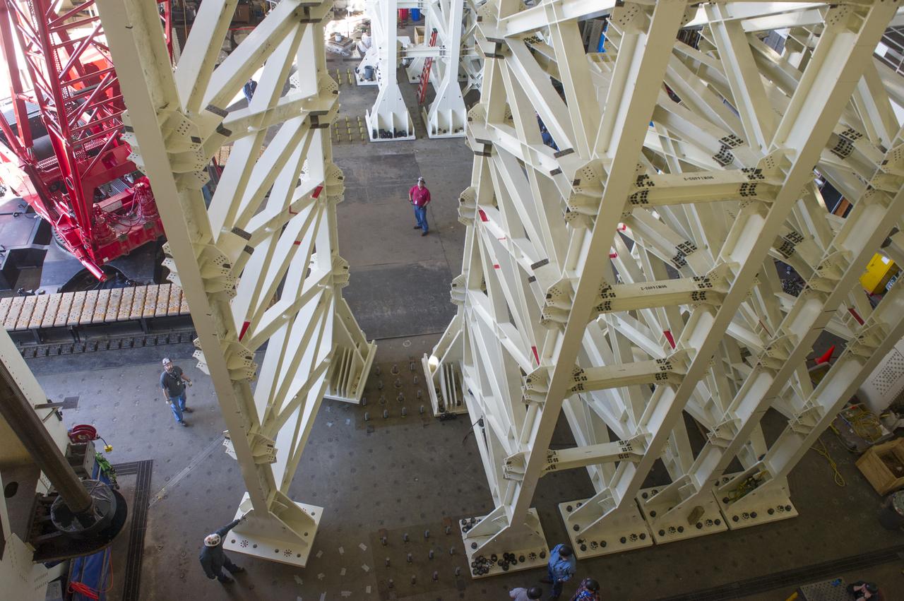
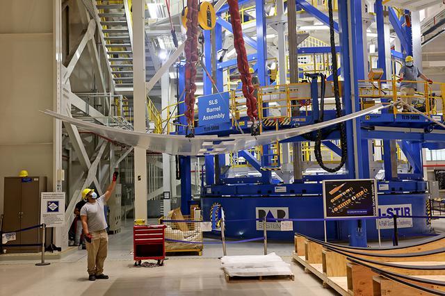
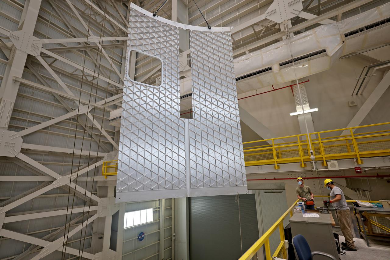
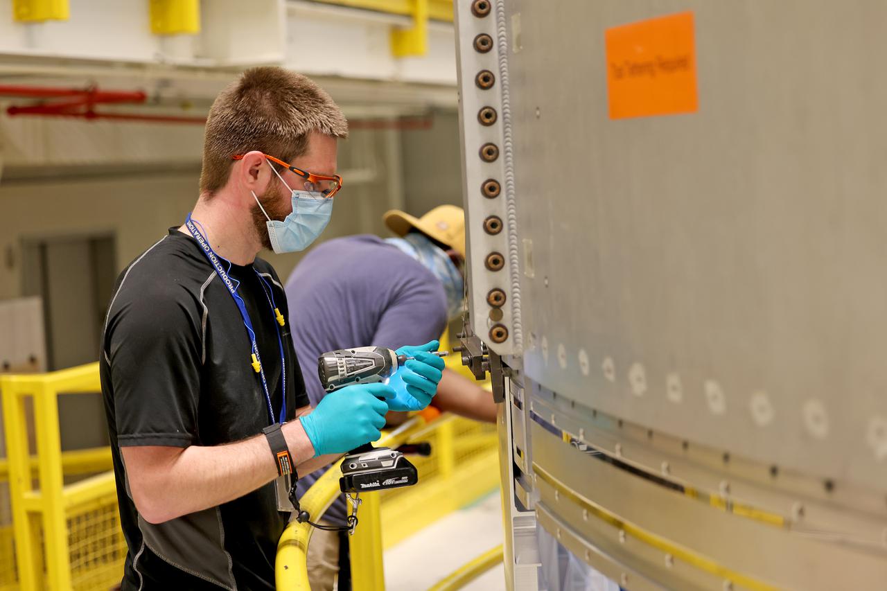
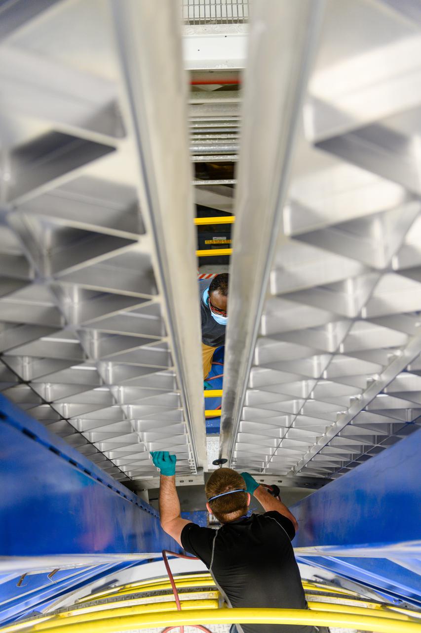
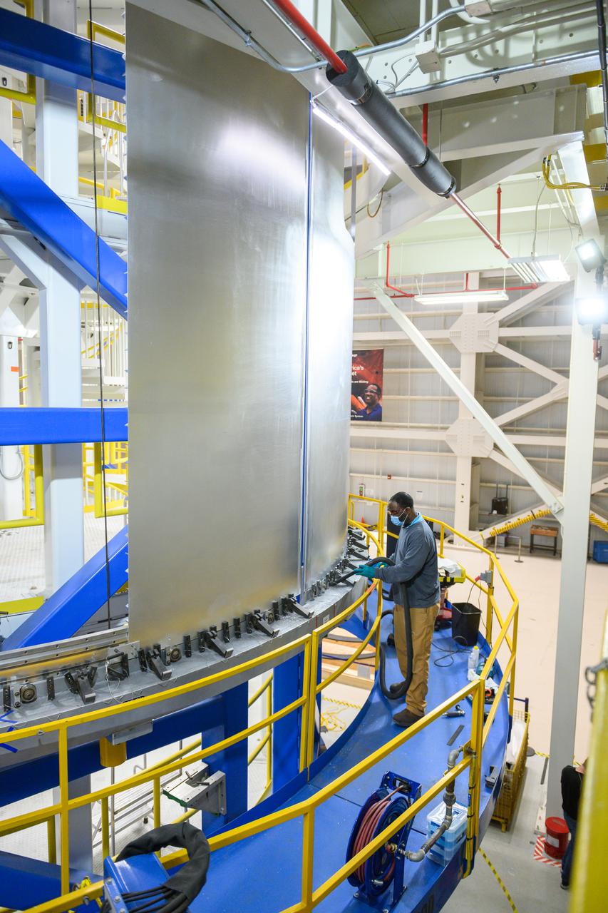
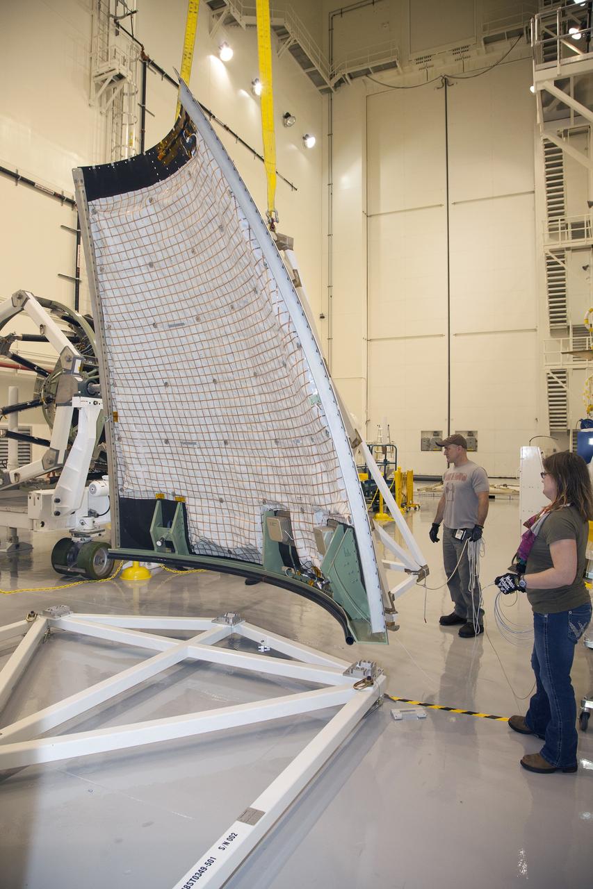
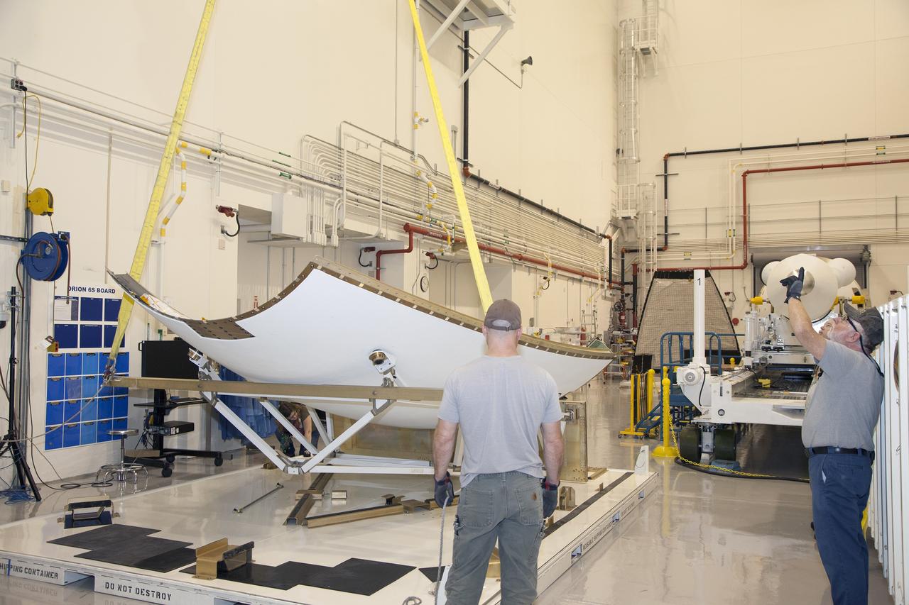
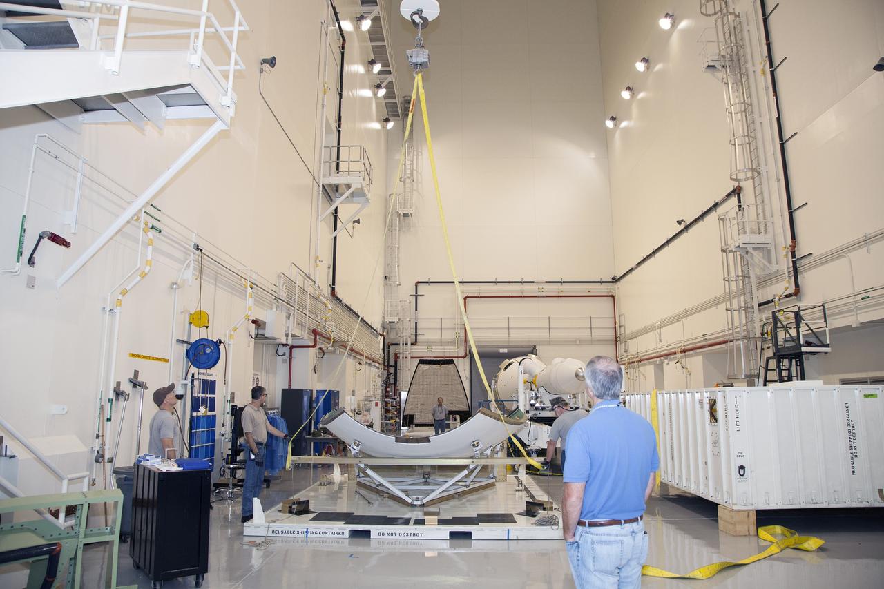
ERECTION OF TWO SLS INTERTANK, (IT), SPECIAL TEST EQUIPMENT, (STE), TOWER PANELS IN BLDG 4619
ERECTION OF TWO SLS INTERTANK, (IT), SPECIAL TEST EQUIPMENT, (STE), TOWER PANELS IN BLDG 4619
ERECTION OF TWO SLS INTERTANK, (IT), SPECIAL TEST EQUIPMENT, (STE), TOWER PANELS IN BLDG 4619
ERECTION OF TWO SLS INTERTANK, (IT), SPECIAL TEST EQUIPMENT, (STE), TOWER PANELS IN BLDG 4619
ERECTION OF TWO SLS INTERTANK, (IT), SPECIAL TEST EQUIPMENT, (STE), TOWER PANELS IN BLDG 4619
ERECTION OF TWO SLS INTERTANK, (IT), SPECIAL TEST EQUIPMENT, (STE), TOWER PANELS IN BLDG 4619
ERECTION OF TWO SLS INTERTANK, (IT), SPECIAL TEST EQUIPMENT, (STE), TOWER PANELS IN BLDG 4619
ERECTION OF TWO SLS INTERTANK, (IT), SPECIAL TEST EQUIPMENT, (STE), TOWER PANELS IN BLDG 4619
ERECTION OF TWO SLS INTERTANK, (IT), SPECIAL TEST EQUIPMENT, (STE), TOWER PANELS IN BLDG 4619
ERECTION OF TWO SLS INTERTANK, (IT), SPECIAL TEST EQUIPMENT, (STE), TOWER PANELS IN BLDG 4619
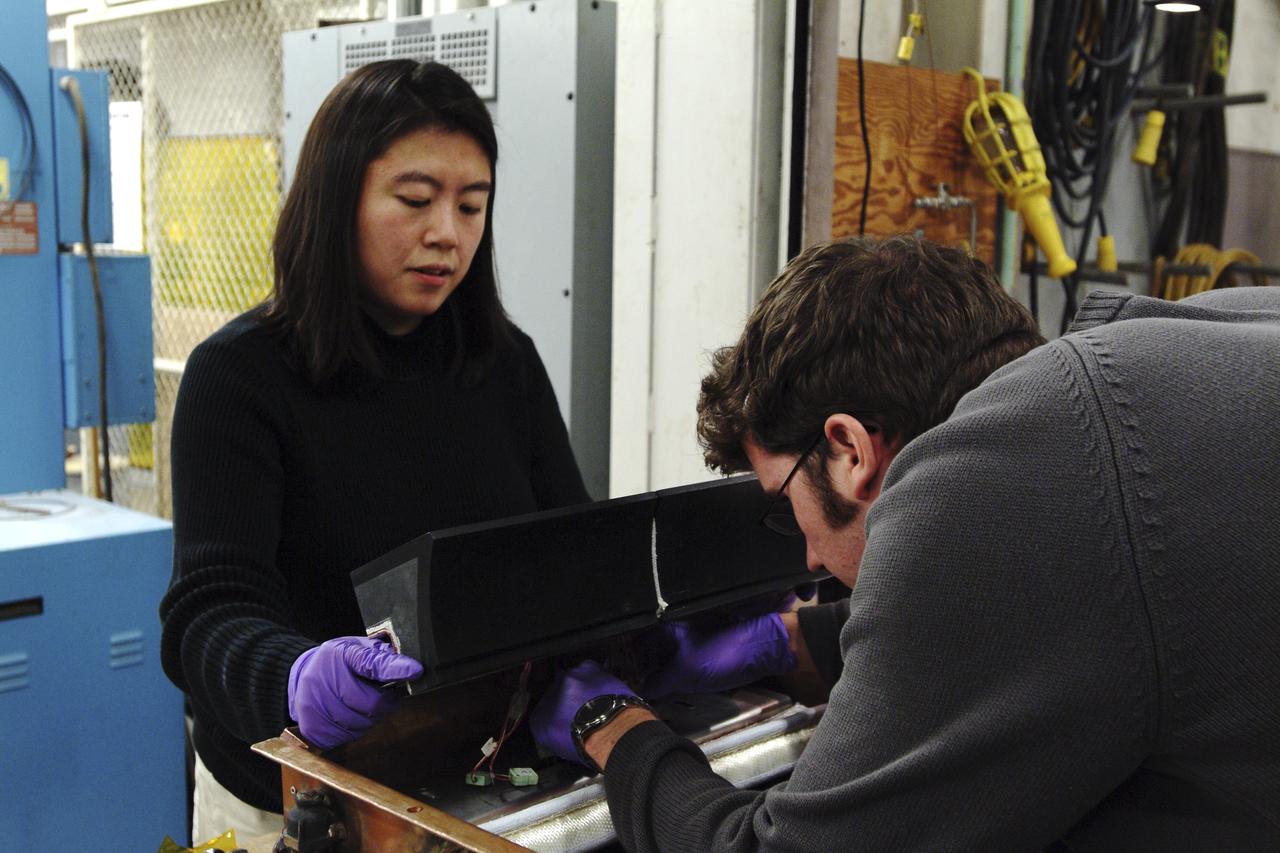
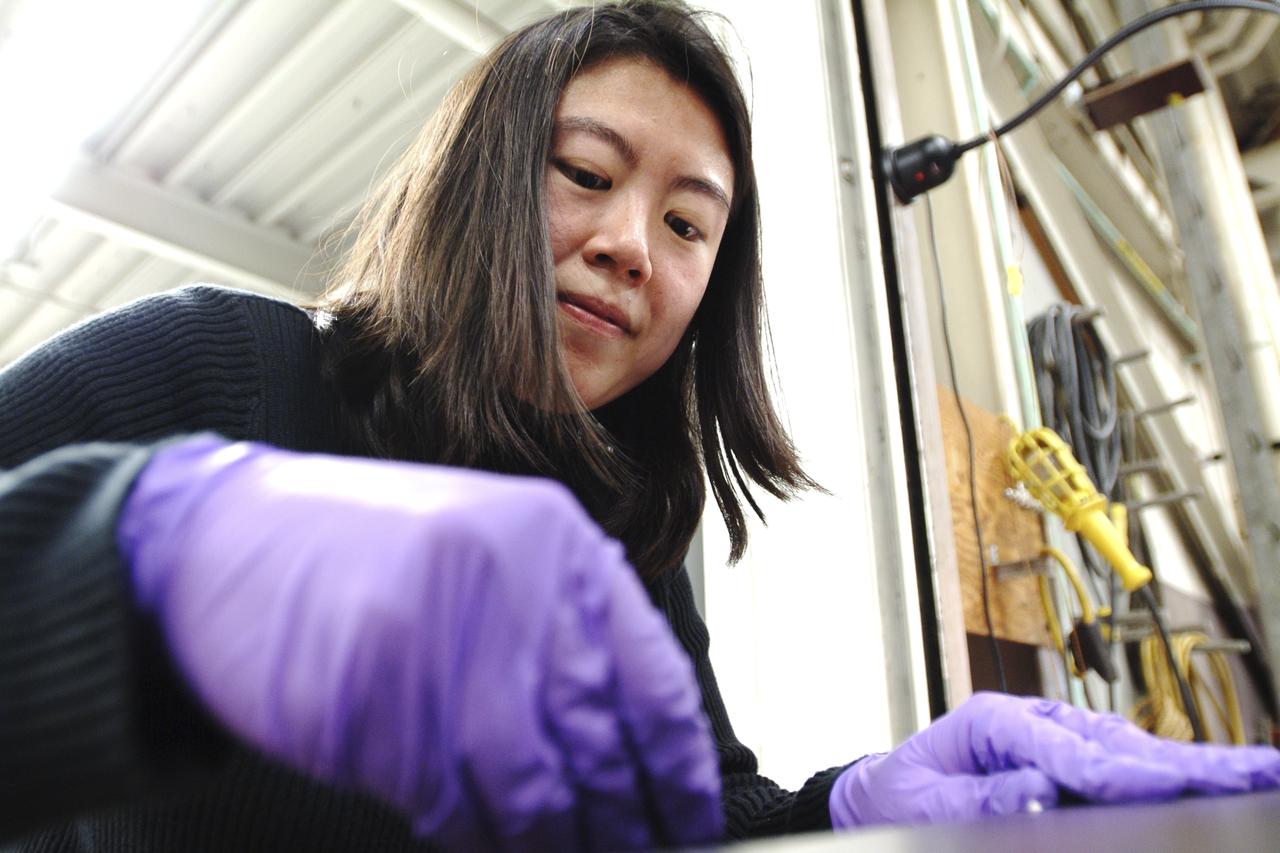
Marshall scientist practices assembling the solar panel array for the space station during the Collector Panel Assembly Test (COPAT) at Marshall's Neutral Buoyancy Simulator (NBS).

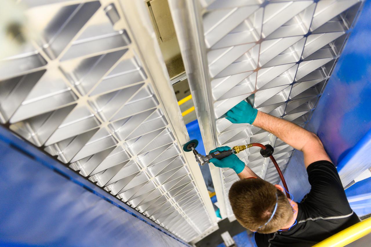
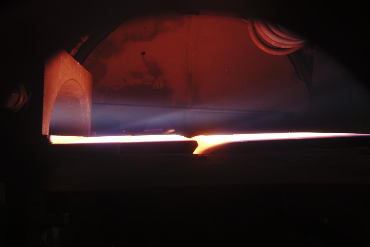
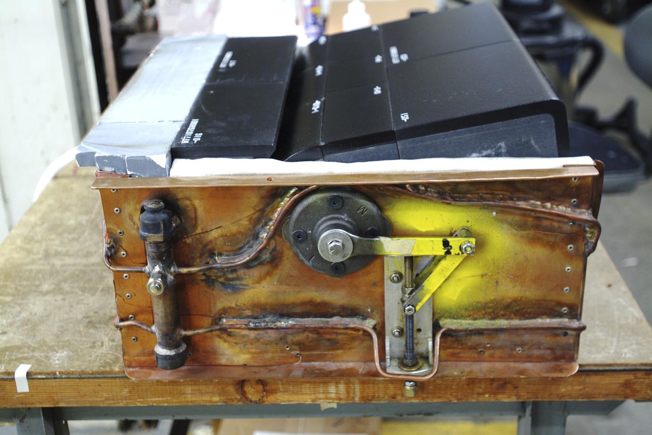
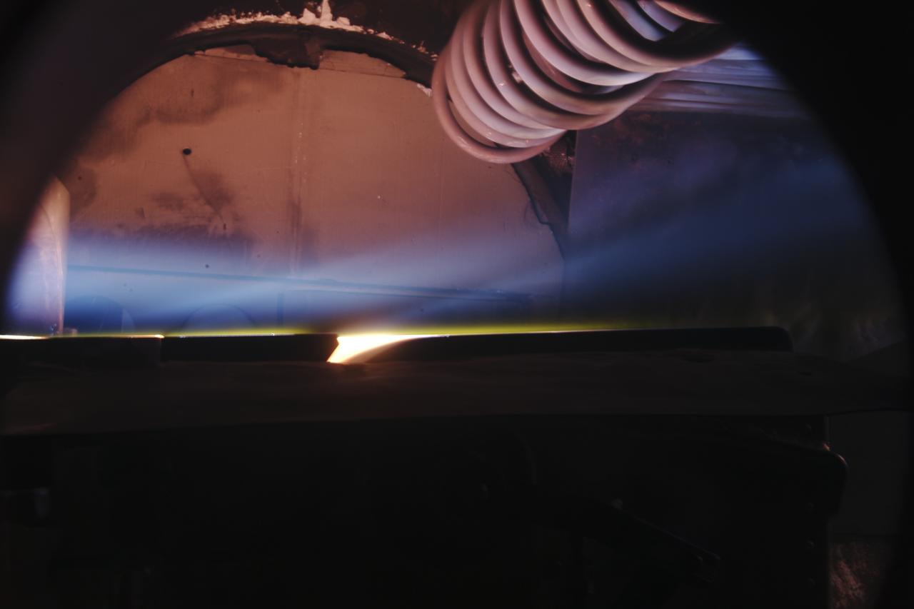
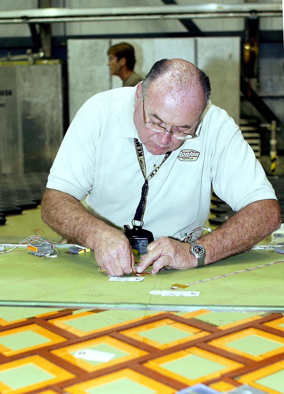
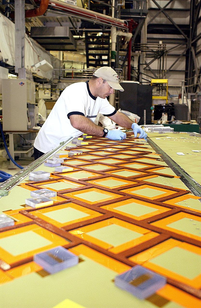
EUS panel test weld at the VXC in Building 115 at the Michoud Assembly Facility on Tuesday, February 9, 2021. Technicians are manufacturing and testing the first in a series of initial weld confidence articles for the Exploration Upper Stage (EUS) for future flights of NASA’s Space Launch System (SLS) rocket at the agency’s Michoud Assembly Facility in New Orleans. The Exploration Upper Stage will be used on the second configuration of the SLS rocket, known as Block 1B, and will provide in-space propulsion to send astronauts in NASA’s Orion spacecraft and heavy cargo on a precise trajectory to the Moon. The Exploration Upper Stage weld confidence panels are first produced in the Vertical Weld Center at Michoud, then small sections of the panels are removed for mechanical testing and analysis in another area of the factory. Teams use weld confidence articles to verify welding procedures, interfaces between the tooling and hardware, and the structural integrity of the welds. Testing of the EUS weld confidence articles will help engineers and technicians validate welding parameters for manufacturing EUS hardware. The first three SLS flights of NASA’s Artemis program will use an interim cryogenic propulsion stage with one RL10 engine to send Orion to the Moon. The SLS Exploration Upper Stage for flights beyond Artemis III has larger propellant tanks and four RL10 engines. The evolution of the rocket to SLS Block 1B configuration with EUS enables SLS to launch 40% more cargo to the Moon along with the crew. Manufacturing the Exploration Upper Stage is a collaborative effort between NASA and Boeing, the lead contractor for EUS and the SLS core stage. SLS is the only rocket that can send Orion, astronauts, and supplies to the Moon in a single mission. The SLS rocket, NASA’s Orion spacecraft, Gateway, and human landing system are part of NASA’s backbone for deep space exploration. Under the Artemis program, NASA is working to land the first woman and the next man on the Moon to pave the way for sustainable exploration at the Moon and future missions to Mars. (NASA)
EUS panel test weld at the VXC in Building 115 at the Michoud Assembly Facility on Tuesday, February 9, 2021. Technicians are manufacturing and testing the first in a series of initial weld confidence articles for the Exploration Upper Stage (EUS) for future flights of NASA’s Space Launch System (SLS) rocket at the agency’s Michoud Assembly Facility in New Orleans. The Exploration Upper Stage will be used on the second configuration of the SLS rocket, known as Block 1B, and will provide in-space propulsion to send astronauts in NASA’s Orion spacecraft and heavy cargo on a precise trajectory to the Moon. The Exploration Upper Stage weld confidence panels are first produced in the Vertical Weld Center at Michoud, then small sections of the panels are removed for mechanical testing and analysis in another area of the factory. Teams use weld confidence articles to verify welding procedures, interfaces between the tooling and hardware, and the structural integrity of the welds. Testing of the EUS weld confidence articles will help engineers and technicians validate welding parameters for manufacturing EUS hardware. The first three SLS flights of NASA’s Artemis program will use an interim cryogenic propulsion stage with one RL10 engine to send Orion to the Moon. The SLS Exploration Upper Stage for flights beyond Artemis III has larger propellant tanks and four RL10 engines. The evolution of the rocket to SLS Block 1B configuration with EUS enables SLS to launch 40% more cargo to the Moon along with the crew. Manufacturing the Exploration Upper Stage is a collaborative effort between NASA and Boeing, the lead contractor for EUS and the SLS core stage. SLS is the only rocket that can send Orion, astronauts, and supplies to the Moon in a single mission. The SLS rocket, NASA’s Orion spacecraft, Gateway, and human landing system are part of NASA’s backbone for deep space exploration. Under the Artemis program, NASA is working to land the first woman and the next man on the Moon to pave the way for sustainable exploration at the Moon and future missions to Mars. (NASA)

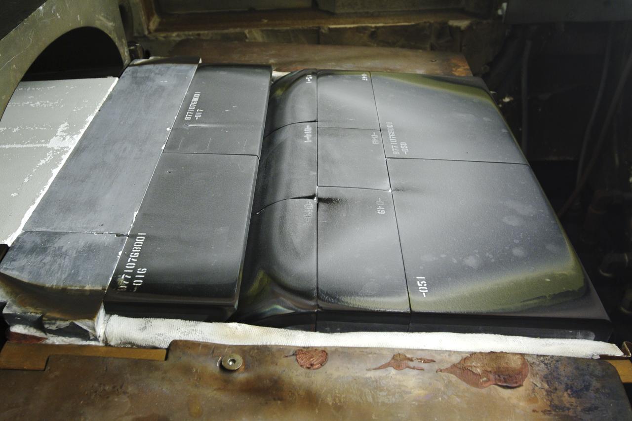
Lift of three EUS test panels in VWC at Michoud Assembly Facility on Thursday, February 11, 2021. Technicians are manufacturing and testing the first in a series of initial weld confidence articles for the Exploration Upper Stage (EUS) for future flights of NASA’s Space Launch System (SLS) rocket at the agency’s Michoud Assembly Facility in New Orleans. The Exploration Upper Stage will be used on the second configuration of the SLS rocket, known as Block 1B, and will provide in-space propulsion to send astronauts in NASA’s Orion spacecraft and heavy cargo on a precise trajectory to the Moon. The Exploration Upper Stage weld confidence panels are first produced in the Vertical Weld Center at Michoud, then small sections of the panels are removed for mechanical testing and analysis in another area of the factory. Teams use weld confidence articles to verify welding procedures, interfaces between the tooling and hardware, and the structural integrity of the welds. Testing of the EUS weld confidence articles will help engineers and technicians validate welding parameters for manufacturing EUS hardware. The first three SLS flights of NASA’s Artemis program will use an interim cryogenic propulsion stage with one RL10 engine to send Orion to the Moon. The SLS Exploration Upper Stage for flights beyond Artemis III has larger propellant tanks and four RL10 engines. The evolution of the rocket to SLS Block 1B configuration with EUS enables SLS to launch 40% more cargo to the Moon along with the crew. Manufacturing the Exploration Upper Stage is a collaborative effort between NASA and Boeing, the lead contractor for EUS and the SLS core stage. SLS is the only rocket that can send Orion, astronauts, and supplies to the Moon in a single mission. The SLS rocket, NASA’s Orion spacecraft, Gateway, and human landing system are part of NASA’s backbone for deep space exploration. Under the Artemis program, NASA is working to land the first woman and the next man on the Moon to pave the way for sustainable exploration at the Moon and future missions to Mars. (NASA)
Lift of three EUS test panels in VWC at Michoud Assembly Facility on Thursday, February 11, 2021. Technicians are manufacturing and testing the first in a series of initial weld confidence articles for the Exploration Upper Stage (EUS) for future flights of NASA’s Space Launch System (SLS) rocket at the agency’s Michoud Assembly Facility in New Orleans. The Exploration Upper Stage will be used on the second configuration of the SLS rocket, known as Block 1B, and will provide in-space propulsion to send astronauts in NASA’s Orion spacecraft and heavy cargo on a precise trajectory to the Moon. The Exploration Upper Stage weld confidence panels are first produced in the Vertical Weld Center at Michoud, then small sections of the panels are removed for mechanical testing and analysis in another area of the factory. Teams use weld confidence articles to verify welding procedures, interfaces between the tooling and hardware, and the structural integrity of the welds. Testing of the EUS weld confidence articles will help engineers and technicians validate welding parameters for manufacturing EUS hardware. The first three SLS flights of NASA’s Artemis program will use an interim cryogenic propulsion stage with one RL10 engine to send Orion to the Moon. The SLS Exploration Upper Stage for flights beyond Artemis III has larger propellant tanks and four RL10 engines. The evolution of the rocket to SLS Block 1B configuration with EUS enables SLS to launch 40% more cargo to the Moon along with the crew. Manufacturing the Exploration Upper Stage is a collaborative effort between NASA and Boeing, the lead contractor for EUS and the SLS core stage. SLS is the only rocket that can send Orion, astronauts, and supplies to the Moon in a single mission. The SLS rocket, NASA’s Orion spacecraft, Gateway, and human landing system are part of NASA’s backbone for deep space exploration. Under the Artemis program, NASA is working to land the first woman and the next man on the Moon to pave the way for sustainable exploration at the Moon and future missions to Mars. (NASA)
Lift of three EUS test panels in VWC at Michoud Assembly Facility on Thursday, February 11, 2021. Technicians are manufacturing and testing the first in a series of initial weld confidence articles for the Exploration Upper Stage (EUS) for future flights of NASA’s Space Launch System (SLS) rocket at the agency’s Michoud Assembly Facility in New Orleans. The Exploration Upper Stage will be used on the second configuration of the SLS rocket, known as Block 1B, and will provide in-space propulsion to send astronauts in NASA’s Orion spacecraft and heavy cargo on a precise trajectory to the Moon. The Exploration Upper Stage weld confidence panels are first produced in the Vertical Weld Center at Michoud, then small sections of the panels are removed for mechanical testing and analysis in another area of the factory. Teams use weld confidence articles to verify welding procedures, interfaces between the tooling and hardware, and the structural integrity of the welds. Testing of the EUS weld confidence articles will help engineers and technicians validate welding parameters for manufacturing EUS hardware. The first three SLS flights of NASA’s Artemis program will use an interim cryogenic propulsion stage with one RL10 engine to send Orion to the Moon. The SLS Exploration Upper Stage for flights beyond Artemis III has larger propellant tanks and four RL10 engines. The evolution of the rocket to SLS Block 1B configuration with EUS enables SLS to launch 40% more cargo to the Moon along with the crew. Manufacturing the Exploration Upper Stage is a collaborative effort between NASA and Boeing, the lead contractor for EUS and the SLS core stage. SLS is the only rocket that can send Orion, astronauts, and supplies to the Moon in a single mission. The SLS rocket, NASA’s Orion spacecraft, Gateway, and human landing system are part of NASA’s backbone for deep space exploration. Under the Artemis program, NASA is working to land the first woman and the next man on the Moon to pave the way for sustainable exploration at the Moon and future missions to Mars. (NASA)
EUS panel test weld at the VXC in Building 115 at the Michoud Assembly Facility on Tuesday, February 9, 2021. Technicians are manufacturing and testing the first in a series of initial weld confidence articles for the Exploration Upper Stage (EUS) for future flights of NASA’s Space Launch System (SLS) rocket at the agency’s Michoud Assembly Facility in New Orleans. The Exploration Upper Stage will be used on the second configuration of the SLS rocket, known as Block 1B, and will provide in-space propulsion to send astronauts in NASA’s Orion spacecraft and heavy cargo on a precise trajectory to the Moon. The Exploration Upper Stage weld confidence panels are first produced in the Vertical Weld Center at Michoud, then small sections of the panels are removed for mechanical testing and analysis in another area of the factory. Teams use weld confidence articles to verify welding procedures, interfaces between the tooling and hardware, and the structural integrity of the welds. Testing of the EUS weld confidence articles will help engineers and technicians validate welding parameters for manufacturing EUS hardware. The first three SLS flights of NASA’s Artemis program will use an interim cryogenic propulsion stage with one RL10 engine to send Orion to the Moon. The SLS Exploration Upper Stage for flights beyond Artemis III has larger propellant tanks and four RL10 engines. The evolution of the rocket to SLS Block 1B configuration with EUS enables SLS to launch 40% more cargo to the Moon along with the crew. Manufacturing the Exploration Upper Stage is a collaborative effort between NASA and Boeing, the lead contractor for EUS and the SLS core stage. SLS is the only rocket that can send Orion, astronauts, and supplies to the Moon in a single mission. The SLS rocket, NASA’s Orion spacecraft, Gateway, and human landing system are part of NASA’s backbone for deep space exploration. Under the Artemis program, NASA is working to land the first woman and the next man on the Moon to pave the way for sustainable exploration at the Moon and future missions to Mars. (NASA)
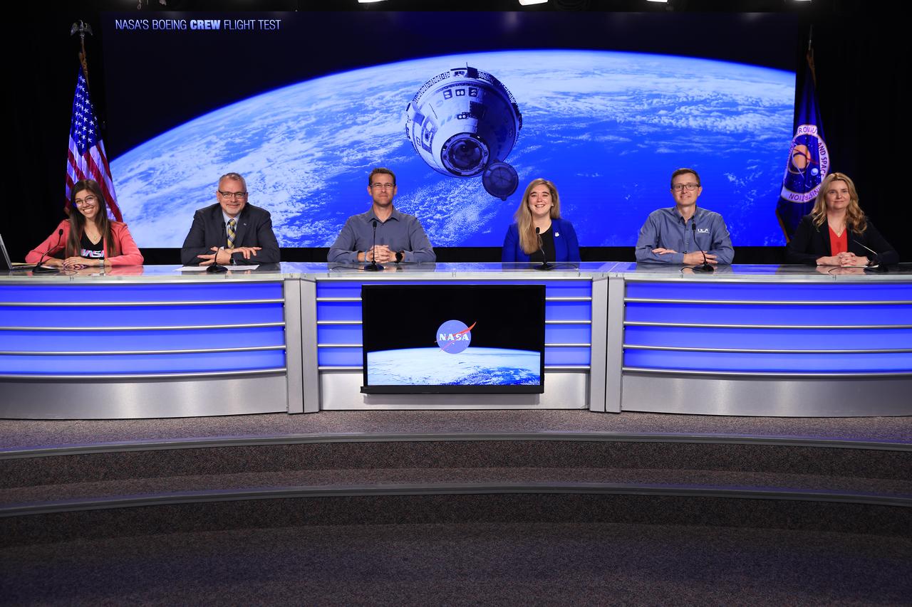
A social media panel discussion takes place at NASA’s Kennedy Space Center in Florida on Friday, May 3, 2024, ahead of NASA’s Boeing Crew Flight Test. Participants, from left to right are Antonia Jaramillo, NASA Communications; Jim Free, NASA associate administrator; Ian Kappes, deputy launch vehicle office manager, NASA’s Commercial Crew Program; Amy Comeau Denker, Starliner associate chief engineer, Boeing; Caleb Weiss, system engineering & test leader, ULA (United Launch Alliance); and Jennifer Buchli, chief scientist, NASA’s International Space Station Program. NASA astronauts Butch Wilmore and Suni Williams are the first to launch aboard Boeing’s Starliner spacecraft atop a ULA Atlas V rocket from Space Launch Complex-41 at Cape Canaveral Space Force Station in Florida. Liftoff is scheduled for 4:43 p.m. ET on Tuesday, May 21.
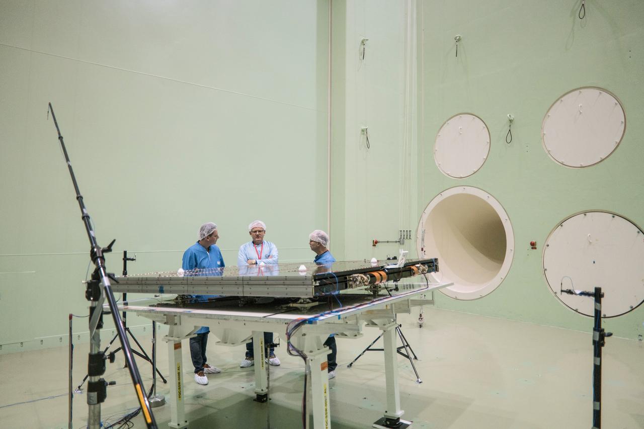
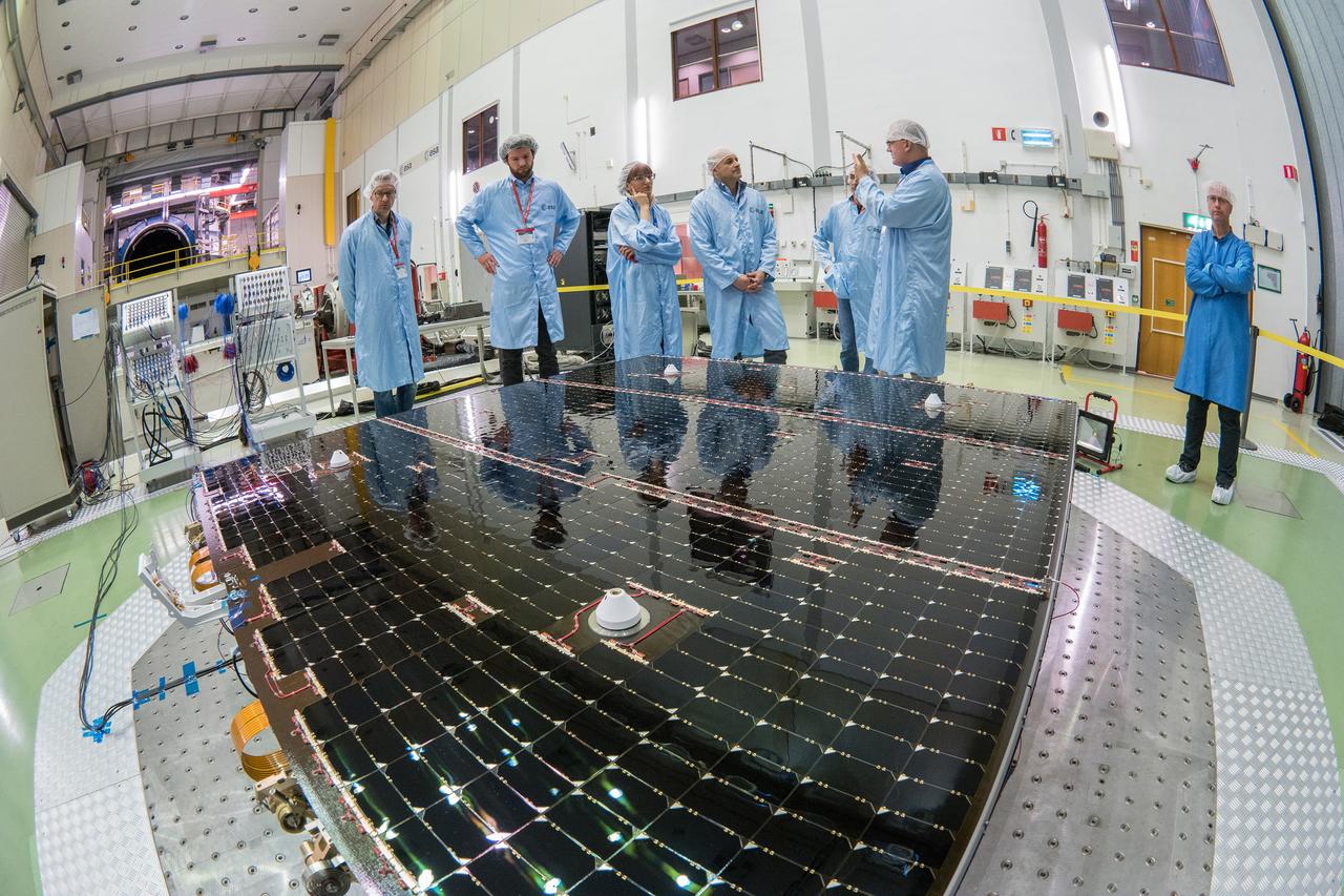
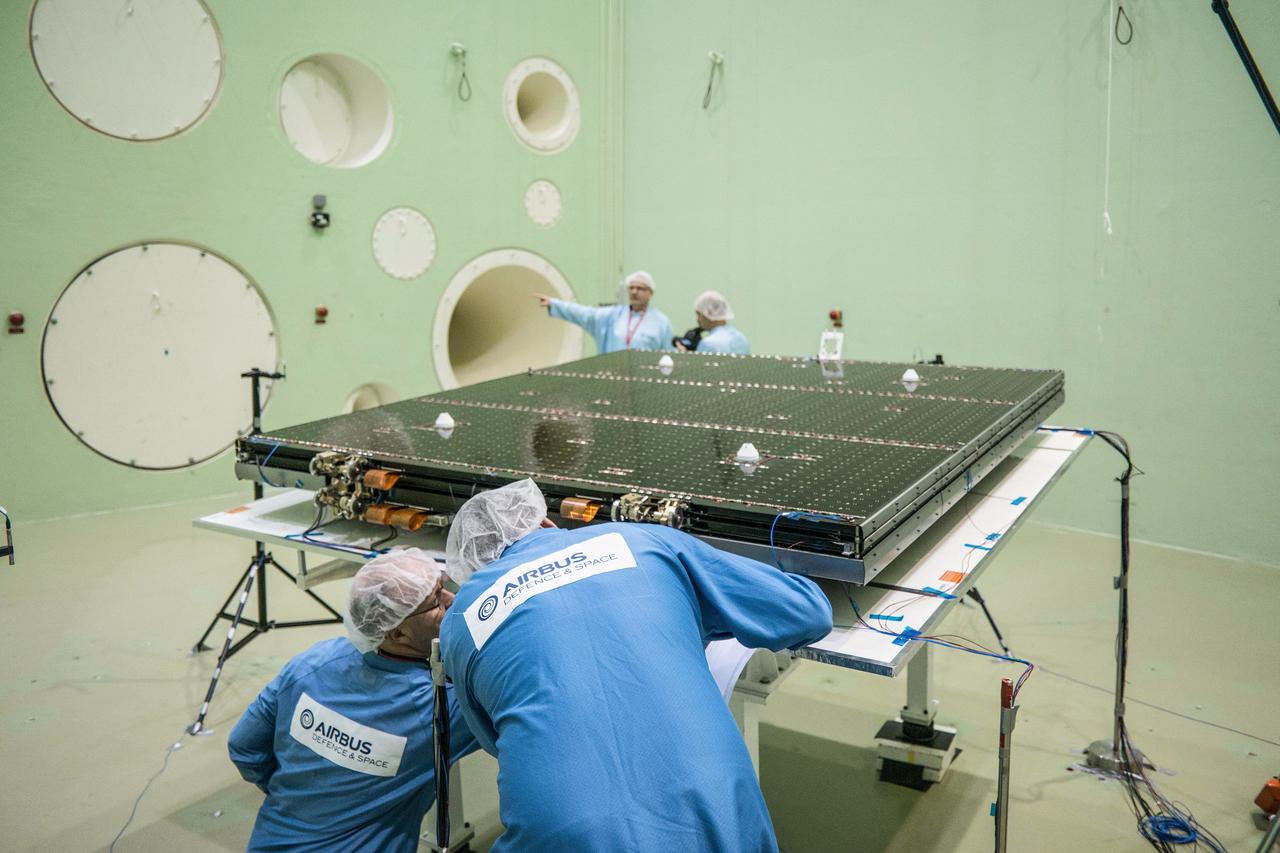
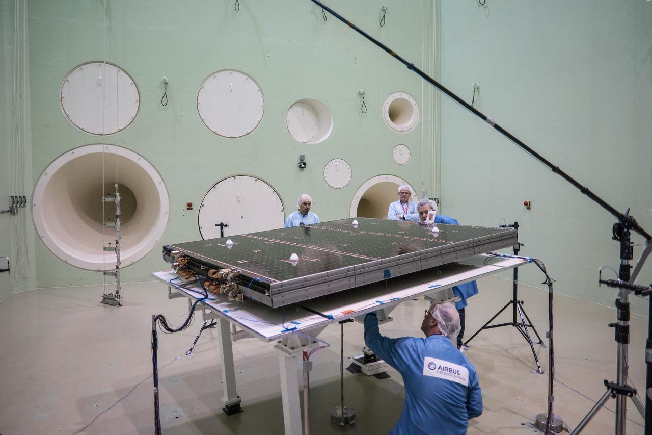
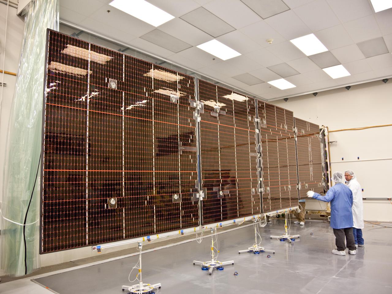
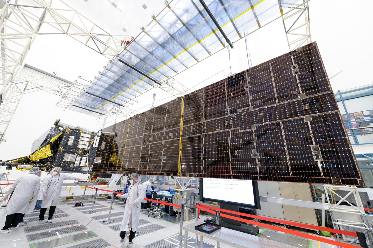
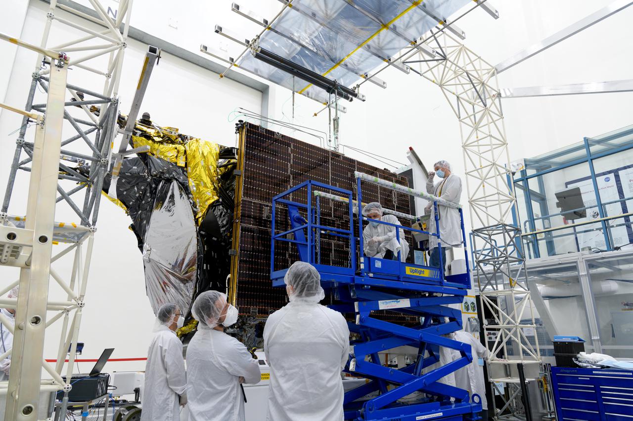
The solar arrays that will provide electricity to the Orion spacecraft were put through launch-day paces at ESA’s Test Centre in the Netherlands to verify that they can handle the rigours of the trip around the Moon... .The wings are seen here on April 11, 2018, on the shaking table that vibrates with the full force of a rumbling rocket. They were also placed in front of enormous speakers that recreate the harsh conditions they can expect on launch day. The solar arrays passed with flying colours... .The wings will be tested on how they deploy before shipping to Bremen, Germany, for integration with the European service module. ESA’s contribution to the Orion mission will provide power, propulsion, water, and air... .The first mission will take Orion around the Moon without astronauts. The solar panels will be folded inside the rocket fairing, once released from NASA’s Space Launch System rocket they will unfold and rotate towards the Sun to start delivering power... .With solar wings tested and fuel tanks installed, Orion is one step closer to its maiden voyage.
The solar arrays that will provide electricity to the Orion spacecraft were put through launch-day paces at ESA’s Test Centre in the Netherlands to verify that they can handle the rigours of the trip around the Moon... .The wings are seen here on April 11, 2018, on the shaking table that vibrates with the full force of a rumbling rocket. They were also placed in front of enormous speakers that recreate the harsh conditions they can expect on launch day. The solar arrays passed with flying colours... .The wings will be tested on how they deploy before shipping to Bremen, Germany, for integration with the European service module. ESA’s contribution to the Orion mission will provide power, propulsion, water, and air... .The first mission will take Orion around the Moon without astronauts. The solar panels will be folded inside the rocket fairing, once released from NASA’s Space Launch System rocket they will unfold and rotate towards the Sun to start delivering power... .With solar wings tested and fuel tanks installed, Orion is one step closer to its maiden voyage.
The solar arrays that will provide electricity to the Orion spacecraft were put through launch-day paces at ESA’s Test Centre in the Netherlands to verify that they can handle the rigours of the trip around the Moon... .The wings are seen here on April 11, 2018, on the shaking table that vibrates with the full force of a rumbling rocket. They were also placed in front of enormous speakers that recreate the harsh conditions they can expect on launch day. The solar arrays passed with flying colours... .The wings will be tested on how they deploy before shipping to Bremen, Germany, for integration with the European service module. ESA’s contribution to the Orion mission will provide power, propulsion, water, and air... .The first mission will take Orion around the Moon without astronauts. The solar panels will be folded inside the rocket fairing, once released from NASA’s Space Launch System rocket they will unfold and rotate towards the Sun to start delivering power... .With solar wings tested and fuel tanks installed, Orion is one step closer to its maiden voyage.
The solar arrays that will provide electricity to the Orion spacecraft were put through launch-day paces at ESA’s Test Centre in the Netherlands to verify that they can handle the rigours of the trip around the Moon... .The wings are seen here on April 11, 2018, on the shaking table that vibrates with the full force of a rumbling rocket. They were also placed in front of enormous speakers that recreate the harsh conditions they can expect on launch day. The solar arrays passed with flying colours... .The wings will be tested on how they deploy before shipping to Bremen, Germany, for integration with the European service module. ESA’s contribution to the Orion mission will provide power, propulsion, water, and air... .The first mission will take Orion around the Moon without astronauts. The solar panels will be folded inside the rocket fairing, once released from NASA’s Space Launch System rocket they will unfold and rotate towards the Sun to start delivering power... .With solar wings tested and fuel tanks installed, Orion is one step closer to its maiden voyage.
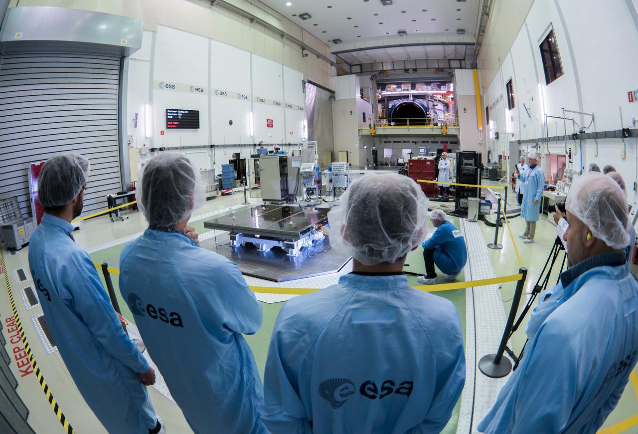
The solar arrays that will provide electricity to the Orion spacecraft were put through launch-day paces at ESA’s Test Centre in the Netherlands to verify that they can handle the rigours of the trip around the Moon... .The wings are seen here on April 11, 2018, on the shaking table that vibrates with the full force of a rumbling rocket. They were also placed in front of enormous speakers that recreate the harsh conditions they can expect on launch day. The solar arrays passed with flying colours... .The wings will be tested on how they deploy before shipping to Bremen, Germany, for integration with the European service module. ESA’s contribution to the Orion mission will provide power, propulsion, water, and air... .The first mission will take Orion around the Moon without astronauts. The solar panels will be folded inside the rocket fairing, once released from NASA’s Space Launch System rocket they will unfold and rotate towards the Sun to start delivering power... .With solar wings tested and fuel tanks installed, Orion is one step closer to its maiden voyage.
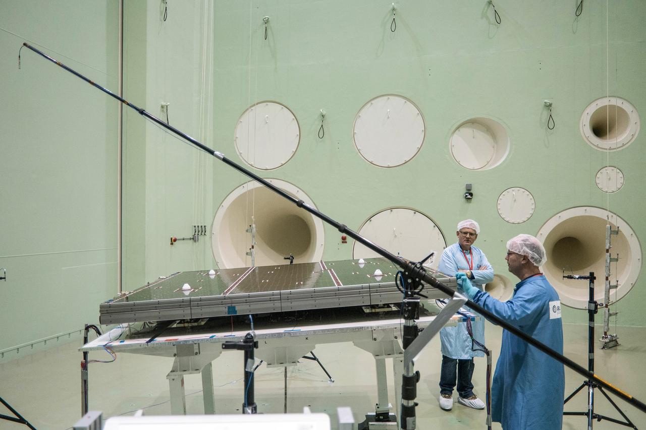
The solar arrays that will provide electricity to the Orion spacecraft were put through launch-day paces at ESA’s Test Centre in the Netherlands to verify that they can handle the rigours of the trip around the Moon... .The wings are seen here on April 11, 2018, on the shaking table that vibrates with the full force of a rumbling rocket. They were also placed in front of enormous speakers that recreate the harsh conditions they can expect on launch day. The solar arrays passed with flying colours... .The wings will be tested on how they deploy before shipping to Bremen, Germany, for integration with the European service module. ESA’s contribution to the Orion mission will provide power, propulsion, water, and air... .The first mission will take Orion around the Moon without astronauts. The solar panels will be folded inside the rocket fairing, once released from NASA’s Space Launch System rocket they will unfold and rotate towards the Sun to start delivering power... .With solar wings tested and fuel tanks installed, Orion is one step closer to its maiden voyage.
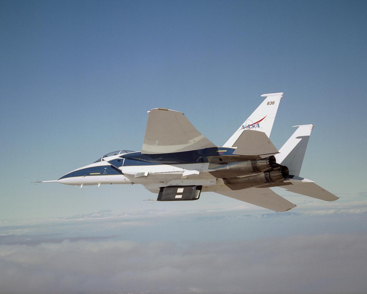
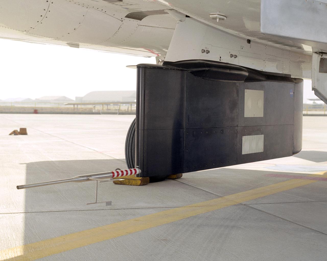
Two panels of Space Shuttle TPS insulation were mounted on the flight test fixture underneath NASA's F-15B during the Lifting Foam Trajectory flight test series.
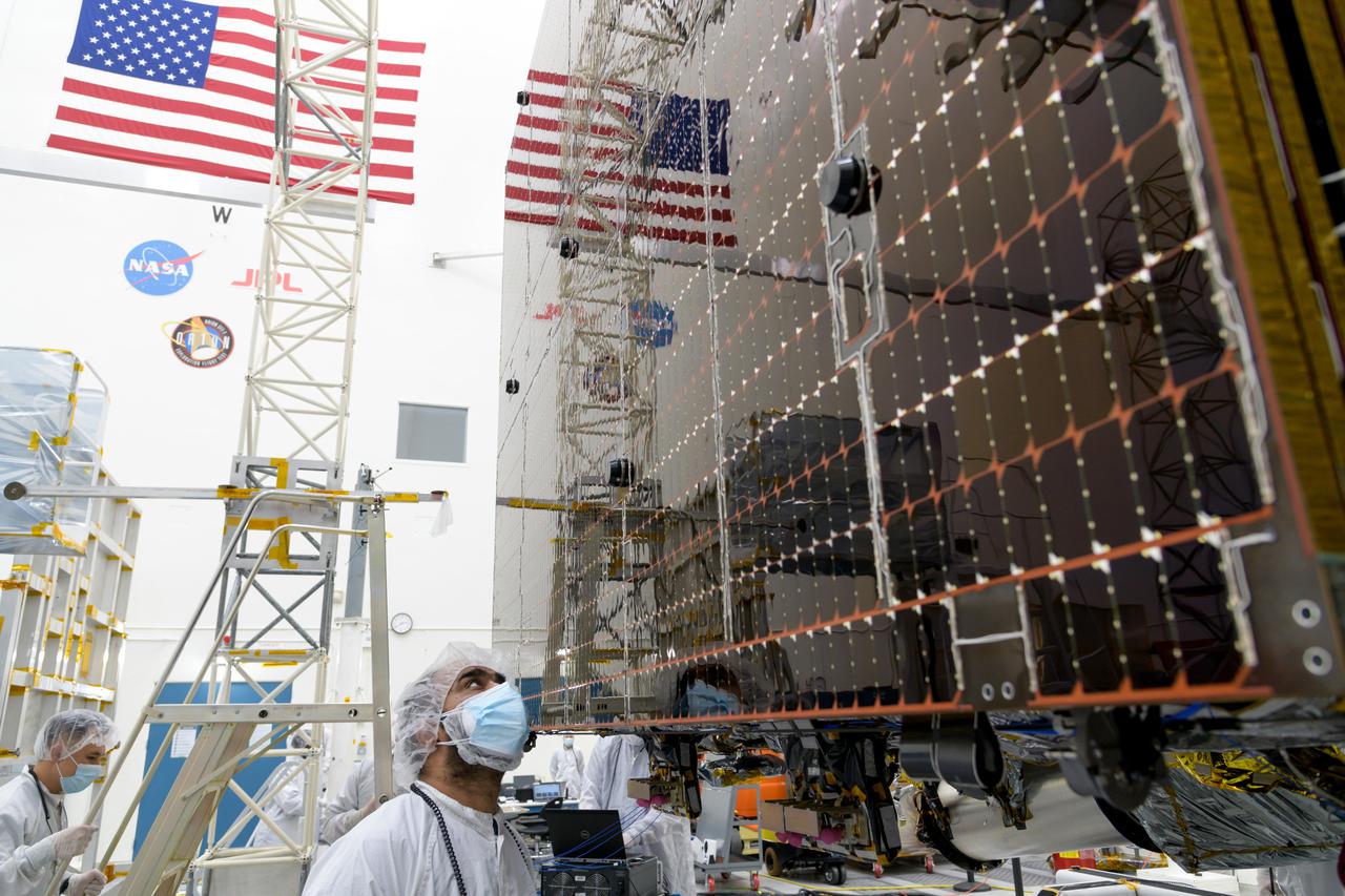
An engineer at NASA's Jet Propulsion Laboratory in Southern California examines a panel on Psyche's stowed solar arrays prior to a deployment test in the Lab's High Bay 2 clean room in February 2022. The twin arrays are together about 800 square feet (75 square meters) – the largest ever deployed at JPL. Part of a solar electric propulsion system provided by Maxar Technologies, they will power the spacecraft on its 1.5 billion-mile (2.4 billion-kilometer) journey to the large, metal-rich asteroid Psyche. Only the three center panels on each five-panel, cross-shaped array can be deployed at JPL due to the limitations of the gravity-offload fixture and the opposing direction of rotation of the cross panels. Deployment of the two cross panels was previously performed at Maxar with different equipment. After further spacecraft testing is completed at JPL, the arrays will be removed and returned to Maxar in order to repeat the cross-panel deployments, make any final repairs to the solar cells, and test overall performance. The arrays then get shipped from Maxar to NASA's Kennedy Space Center in Florida, where they will be reintegrated onto the spacecraft in preparation for launch in August 2022. About an hour after launch, Psyche will deploy the arrays sequentially, first unfolding the three lengthwise center panels, then the two cross panels on one wing before repeating the process with the other wing. Each array takes about 7 ½ minutes to unfurl and latch into place. Each array is 37.1 feet (11.3 meters) long and 24 feet (7.3 meters) wide when fully deployed. With arrays deployed on either side of the chassis, the spacecraft is about the size of a singles tennis court: 81 feet long (24.7 meters) and 24 feet (7.3 meters) wide. https://photojournal.jpl.nasa.gov/catalog/PIA25133
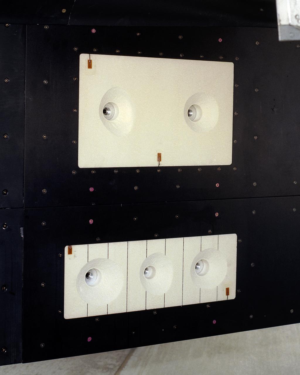
A close-up of the panels on the F-15B's flight test fixture shows five divots of TPS foam were successfully ejected during the LIFT experiment flight #2, the first flight with TPS foam.
A post-flight inspection of the panels on the F-15B's flight test fixture shows five divots of TPS foam were successfully ejected during the LIFT experiment flight #2, the first flight with TPS foam.
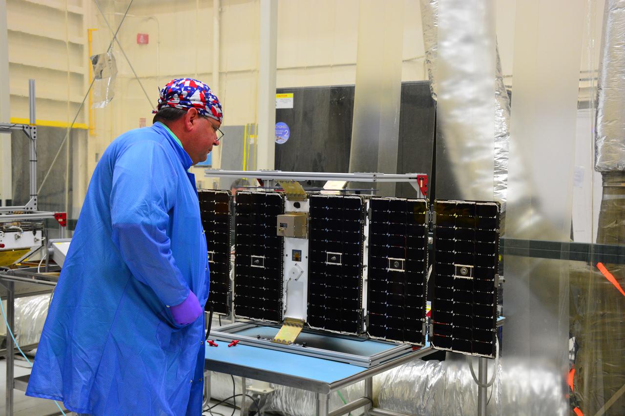
Inside Building 1555 at Vandenberg Air Force Base in California, solar panels for one of eight NASA's Cyclone Global Navigation Satellite System (CYGNSS) spacecraft has been deployed for illumination testing. Processing activities will prepare the spacecraft for launch aboard an Orbital ATK Pegasus XL rocket. When preparations are completed at Vandenberg, the rocket will be transported to NASA's Kennedy Space Center in Florida attached to the Orbital ATK L-1011 carrier aircraft within its payload fairing. CYGNSS will launch on the Pegasus XL rocket from the Skid Strip at Cape Canaveral Air Force Station. CYGNSS will make frequent and accurate measurements of ocean surface winds throughout the life cycle of tropical storms and hurricanes. The data that CYGNSS provides will enable scientists to probe key air-sea interaction processes that take place near the core of storms, which are rapidly changing and play a critical role in the beginning and intensification of hurricanes.
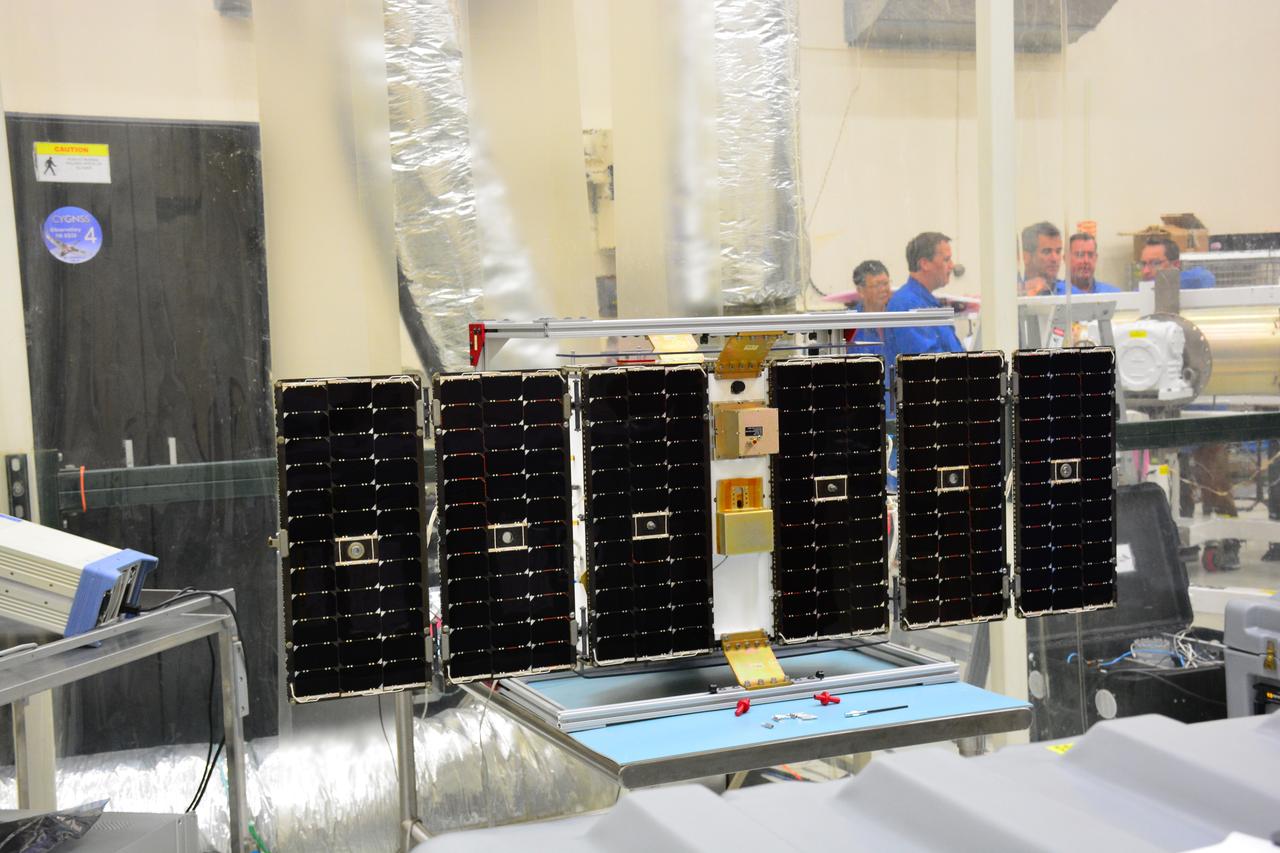
Inside Building 1555 at Vandenberg Air Force Base in California, solar panels for one of eight NASA's Cyclone Global Navigation Satellite System (CYGNSS) spacecraft has been deployed for illumination testing. Processing activities will prepare the spacecraft for launch aboard an Orbital ATK Pegasus XL rocket. When preparations are completed at Vandenberg, the rocket will be transported to NASA's Kennedy Space Center in Florida attached to the Orbital ATK L-1011 carrier aircraft within its payload fairing. CYGNSS will launch on the Pegasus XL rocket from the Skid Strip at Cape Canaveral Air Force Station. CYGNSS will make frequent and accurate measurements of ocean surface winds throughout the life cycle of tropical storms and hurricanes. The data that CYGNSS provides will enable scientists to probe key air-sea interaction processes that take place near the core of storms, which are rapidly changing and play a critical role in the beginning and intensification of hurricanes.

It no easy task getting NASA Mars Reconnaissance Orbiter ready for launch. Workers stabilize the crane holding one of the enormous billboard-sized solar panels temporarily removed from the spacecraft prior to rigorous testing.
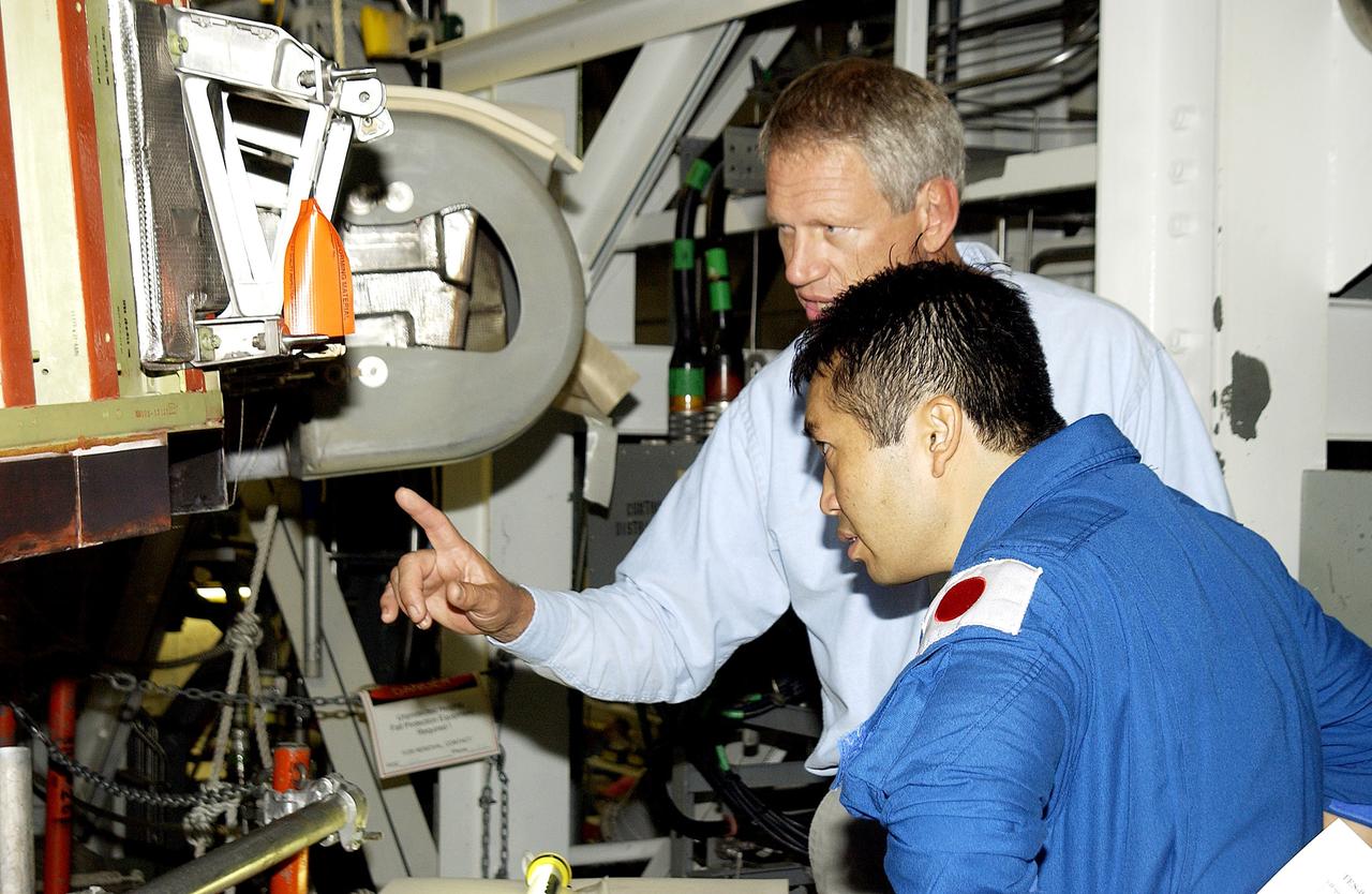
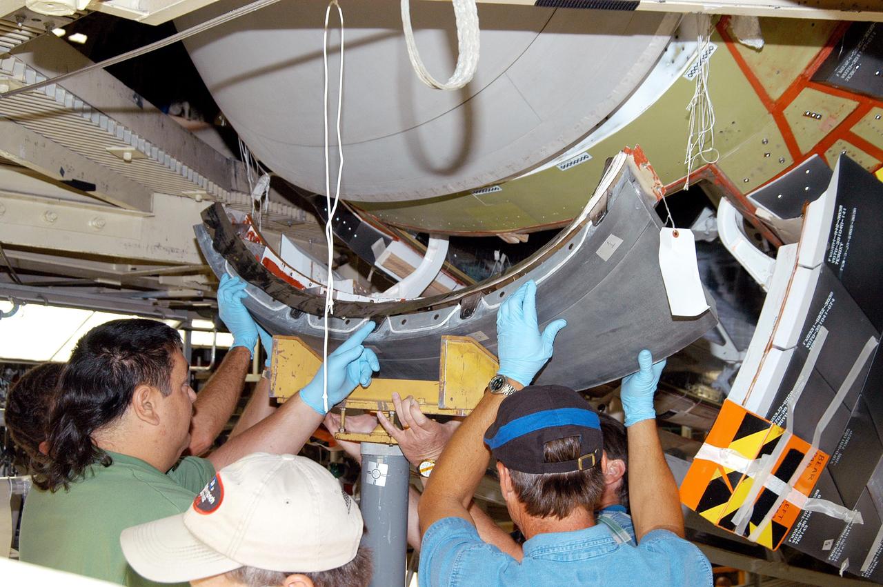
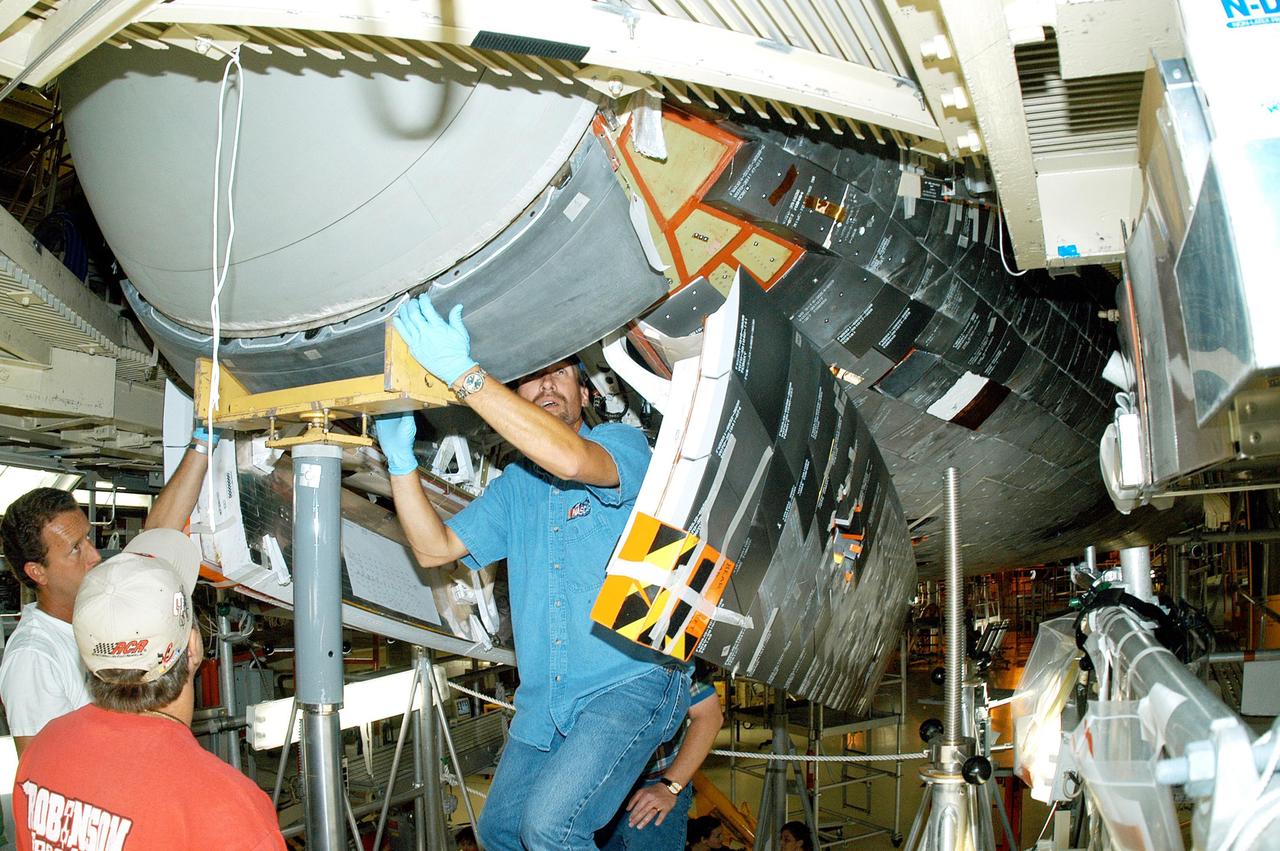
KENNEDY SPACE CENTER, FLA. - Japanese astronaut Koichi Wakata (front) listens to William Gaetjens, with the Vehicle Integration Test Team (VITT), who is providing details about the spar installation (left) on the wing of the orbiter Atlantis. Reinforced Carbon Carbon (RCC) panels are mechanically attached to the wing via the spars - a series of floating joints - to reduce loading on the panels caused by wing deflections. The aluminum and the metallic attachments are protected from exceeding temperature limits by internal insulation.
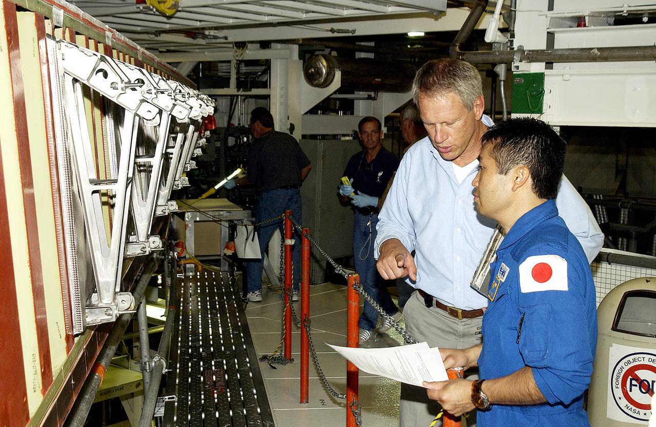
KENNEDY SPACE CENTER, FLA. - Japanese astronaut Koichi Wakata (right) listens to William Gaetjens, with the Vehicle Integration Test Team (VITT), who is providing details about the spar installation (left) on the wing of the orbiter Atlantis. Reinforced Carbon Carbon (RCC) panels are mechanically attached to the wing via the spars - a series of floating joints - to reduce loading on the panels caused by wing deflections. The aluminum and the metallic attachments are protected from exceeding temperature limits by internal insulation.
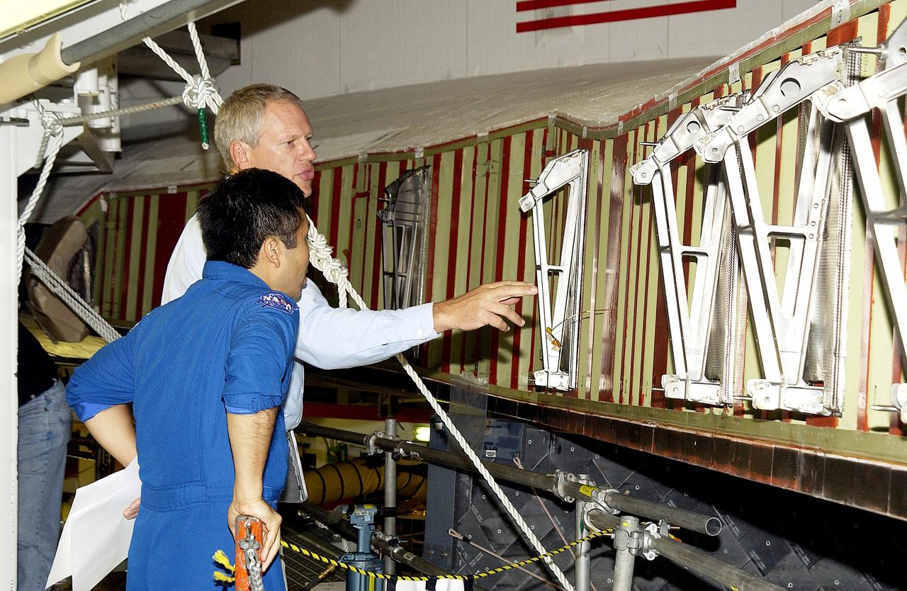
KENNEDY SPACE CENTER, FLA. - William Gaetjens (background), with the Vehicle Integration Test Team (VITT) directs Japanese astronaut Koichi Wakata’s attention to the spars installed on the wing of the orbiter Atlantis. Reinforced Carbon Carbon (RCC) panels are mechanically attached to the wing via the spars - a series of floating joints - to reduce loading on the panels caused by wing deflections. The aluminum and the metallic attachments are protected from exceeding temperature limits by internal insulation.
Technicians test the deployment of one of the three massive solar arrays that power NASA Juno spacecraft.
Technicians test the deployment of one of the three massive solar arrays that power NASA Juno spacecraft.
Technicians test the deployment of one of the three massive solar arrays that power NASA Juno spacecraft.
The OSAM-1 integration and testing team deploys and stows the radiator panels on the OSAM-1 servicing payload at Goddard Space Flight Center, Greenbelt Md., Sept 14, 2023. This photo has been reviewed by OSAM1 project management and the Export Control Office and is released for public view. NASA/Mike Guinto
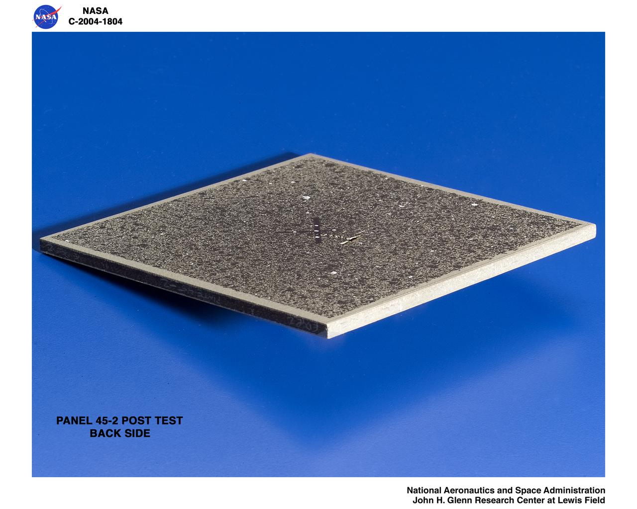
carbon/carbon fiber panels, panel 45-2 post test 90 degree ice impact
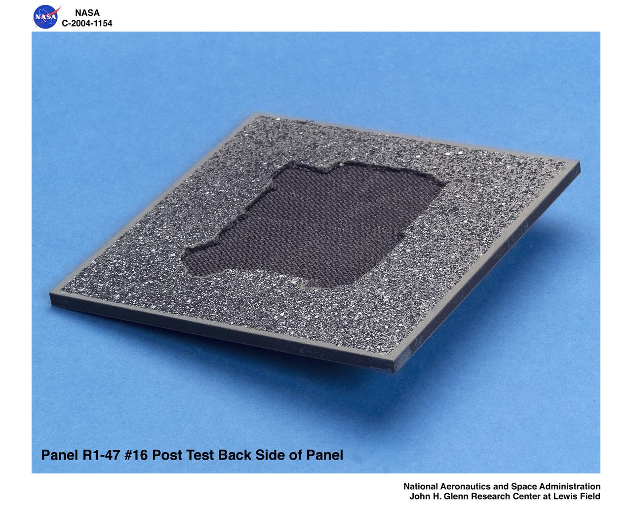
carbon/carbon fiber panels, panel R1-47-16 post test isometric view of back side
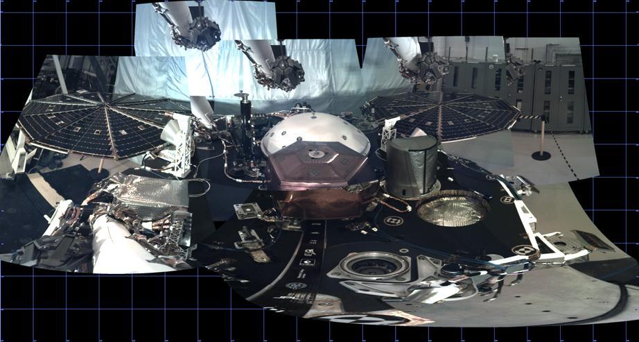
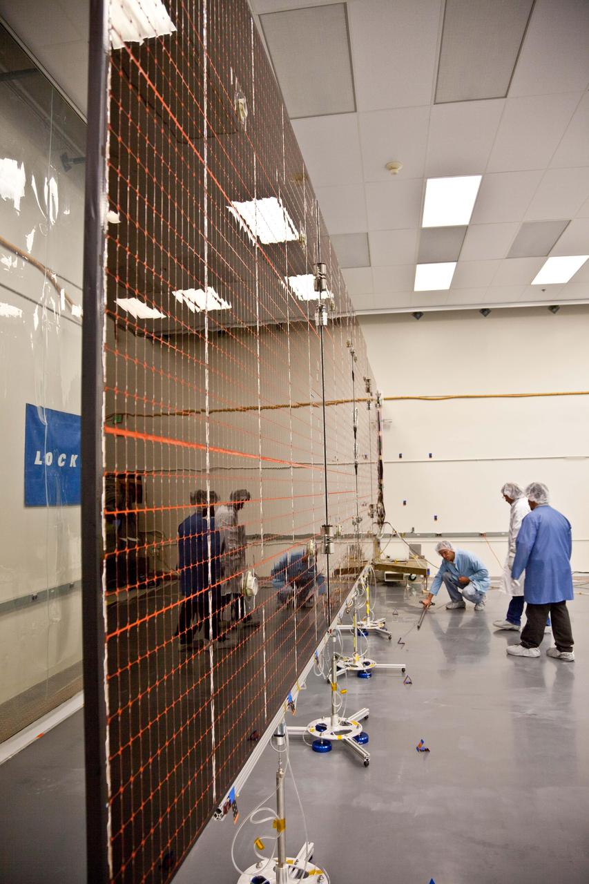
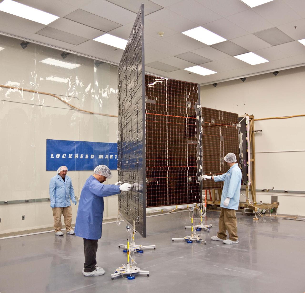
This panorama, created from multiple images, shows the deck of NASA's InSight lander, as well as its solar panels, during the assembly, test and launch operations phase at Lockheed Martin Space, Denver. The panorama, which uses images from InSight's Instrument Deployment Camera on its robotic arm, is a cylindrical projection. https://photojournal.jpl.nasa.gov/catalog/PIA22826
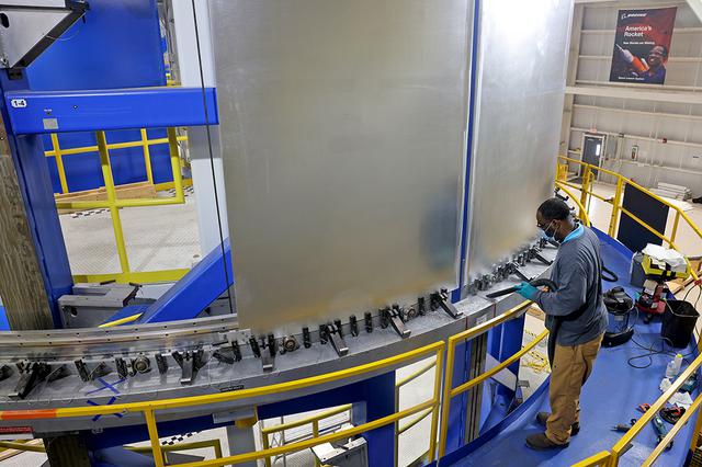
Technicians are manufacturing and testing the first in a series of initial weld confidence articles for the Exploration Upper Stage (EUS) for future flights of NASA’s Space Launch System (SLS) rocket at the agency’s Michoud Assembly Facility in New Orleans. The Exploration Upper Stage will be used on the second configuration of the SLS rocket, known as Block 1B, and will provide in-space propulsion to send astronauts in NASA’s Orion spacecraft and heavy cargo on a precise trajectory to the Moon. The Exploration Upper Stage weld confidence panels are first produced in the Vertical Weld Center at Michoud, then small sections of the panels are removed for mechanical testing and analysis in another area of the factory. Teams use weld confidence articles to verify welding procedures, interfaces between the tooling and hardware, and the structural integrity of the welds. Testing of the EUS weld confidence articles will help engineers and technicians validate welding parameters for manufacturing EUS hardware. The first three SLS flights of NASA’s Artemis program will use an interim cryogenic propulsion stage with one RL10 engine to send Orion to the Moon. The SLS Exploration Upper Stage for flights beyond Artemis III has larger propellant tanks and four RL10 engines. The evolution of the rocket to SLS Block 1B configuration with EUS enables SLS to launch 40% more cargo to the Moon along with the crew. Manufacturing the Exploration Upper Stage is a collaborative effort between NASA and Boeing, the lead contractor for EUS and the SLS core stage. SLS is the only rocket that can send Orion, astronauts, and supplies to the Moon in a single mission. The SLS rocket, NASA’s Orion spacecraft, Gateway, and human landing system are part of NASA’s backbone for deep space exploration. Under the Artemis program, NASA is working to land the first woman and the next man on the Moon to pave the way for sustainable exploration at the Moon and future missions to Mars. (NASA)
Technicians are manufacturing and testing the first in a series of initial weld confidence articles for the Exploration Upper Stage (EUS) for future flights of NASA’s Space Launch System (SLS) rocket at the agency’s Michoud Assembly Facility in New Orleans. The Exploration Upper Stage will be used on the second configuration of the SLS rocket, known as Block 1B, and will provide in-space propulsion to send astronauts in NASA’s Orion spacecraft and heavy cargo on a precise trajectory to the Moon. The Exploration Upper Stage weld confidence panels are first produced in the Vertical Weld Center at Michoud, then small sections of the panels are removed for mechanical testing and analysis in another area of the factory. Teams use weld confidence articles to verify welding procedures, interfaces between the tooling and hardware, and the structural integrity of the welds. Testing of the EUS weld confidence articles will help engineers and technicians validate welding parameters for manufacturing EUS hardware. The first three SLS flights of NASA’s Artemis program will use an interim cryogenic propulsion stage with one RL10 engine to send Orion to the Moon. The SLS Exploration Upper Stage for flights beyond Artemis III has larger propellant tanks and four RL10 engines. The evolution of the rocket to SLS Block 1B configuration with EUS enables SLS to launch 40% more cargo to the Moon along with the crew. Manufacturing the Exploration Upper Stage is a collaborative effort between NASA and Boeing, the lead contractor for EUS and the SLS core stage. SLS is the only rocket that can send Orion, astronauts, and supplies to the Moon in a single mission. The SLS rocket, NASA’s Orion spacecraft, Gateway, and human landing system are part of NASA’s backbone for deep space exploration. Under the Artemis program, NASA is working to land the first woman and the next man on the Moon to pave the way for sustainable exploration at the Moon and future missions to Mars. (NASA)
Technicians are manufacturing and testing the first in a series of initial weld confidence articles for the Exploration Upper Stage (EUS) for future flights of NASA’s Space Launch System (SLS) rocket at the agency’s Michoud Assembly Facility in New Orleans. The Exploration Upper Stage will be used on the second configuration of the SLS rocket, known as Block 1B, and will provide in-space propulsion to send astronauts in NASA’s Orion spacecraft and heavy cargo on a precise trajectory to the Moon. The Exploration Upper Stage weld confidence panels are first produced in the Vertical Weld Center at Michoud, then small sections of the panels are removed for mechanical testing and analysis in another area of the factory. Teams use weld confidence articles to verify welding procedures, interfaces between the tooling and hardware, and the structural integrity of the welds. Testing of the EUS weld confidence articles will help engineers and technicians validate welding parameters for manufacturing EUS hardware. The first three SLS flights of NASA’s Artemis program will use an interim cryogenic propulsion stage with one RL10 engine to send Orion to the Moon. The SLS Exploration Upper Stage for flights beyond Artemis III has larger propellant tanks and four RL10 engines. The evolution of the rocket to SLS Block 1B configuration with EUS enables SLS to launch 40% more cargo to the Moon along with the crew. Manufacturing the Exploration Upper Stage is a collaborative effort between NASA and Boeing, the lead contractor for EUS and the SLS core stage. SLS is the only rocket that can send Orion, astronauts, and supplies to the Moon in a single mission. The SLS rocket, NASA’s Orion spacecraft, Gateway, and human landing system are part of NASA’s backbone for deep space exploration. Under the Artemis program, NASA is working to land the first woman and the next man on the Moon to pave the way for sustainable exploration at the Moon and future missions to Mars. (NASA)
Thermal Evaluaion of X-37 Body flap Seal testing in the Panel Test Facility PFT-115
Thermal Evaluaion of X-37 Body Flap Sea test in Panel Test Facility PTF-115
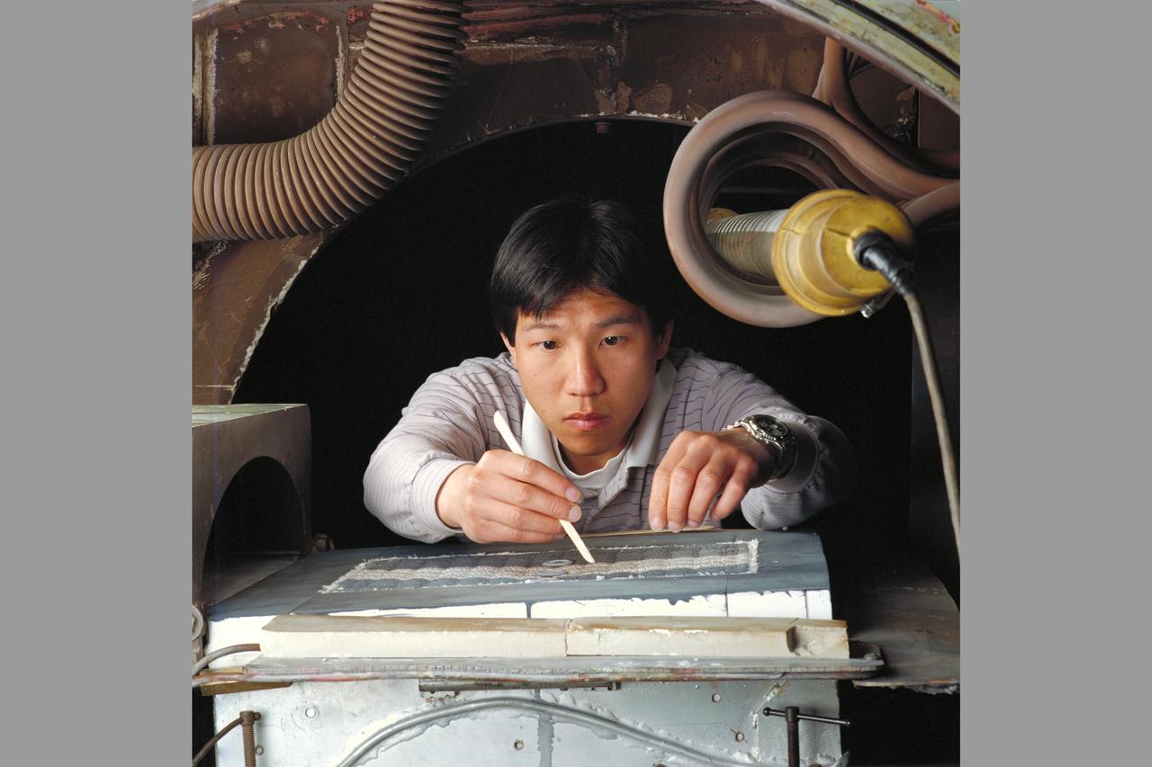
Space Shuttle tile rain erosion test: Frank Hui sets MDA samples in Panel Test Facility for PTF-65
Thermal Evaluaion of X-37 Body Flap Sea test in Panel Test Facility PTF-115
Thermal Evaluaion of X-37 Body Flap Sea test in Panel Test Facility PTF-115
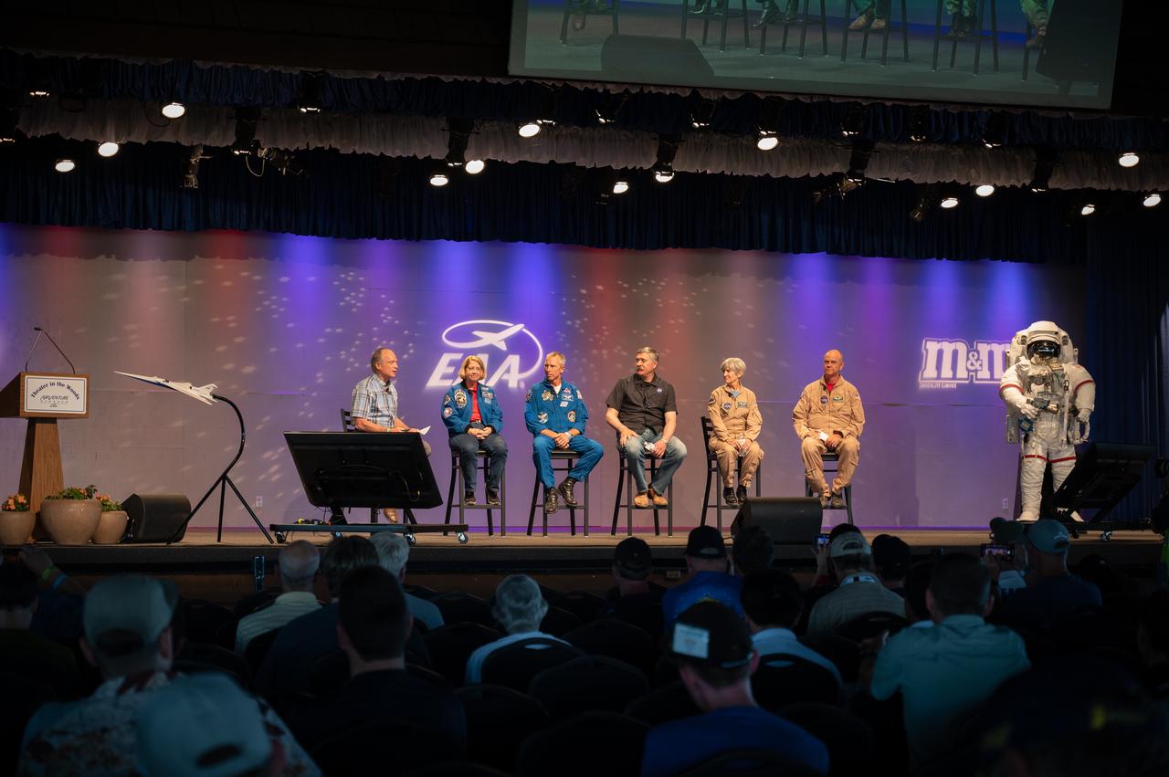
NASA panelists appear at special panel titled “The Next Bold Step: The Future of Space Flight and Aerospace,” on July 29, 2022, at EAA Airventure. Panelists include Deputy Administrator Pam Melroy, Astronaut Drew Feustel, Artemis Mission Manager Michael Sarafin, Research Pilot Liz Ruth and Test Pilot Nils Larson.
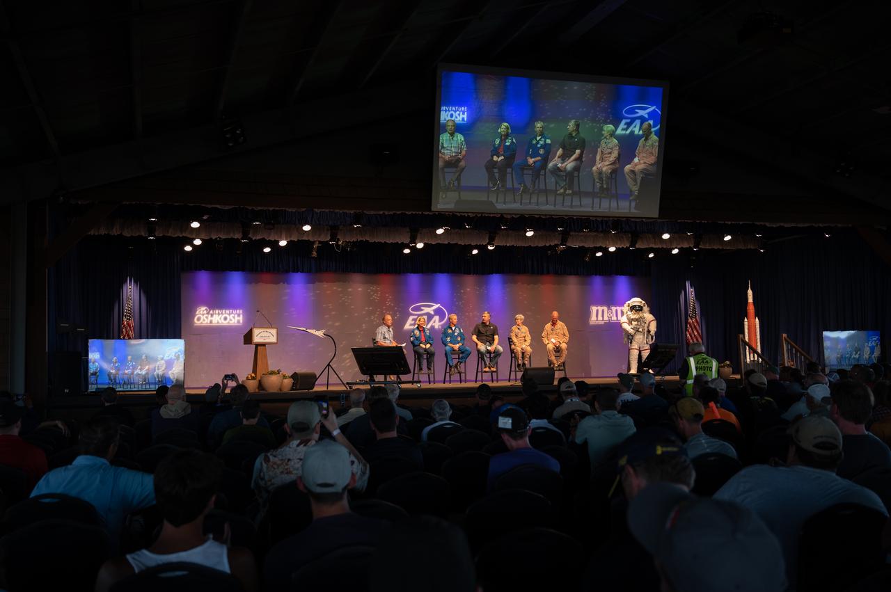
NASA panelists appear at special panel titled “The Next Bold Step: The Future of Space Flight and Aerospace,” on July 29, 2022, at EAA Airventure. Panelists include Deputy Administrator Pam Melroy, Astronaut Drew Feustel, Artemis Mission Manager Michael Sarafin, Research Pilot Liz Ruth and Test Pilot Nils Larson.
Thermal Evaluaion of X-37 Body Flap Sea test in Panel Test Facility PTF-115 With Winnie Chen, and Patric Briney, Boeing test engineers
Thermal Evaluaion of X-37 Body Flap Sea test in Panel Test Facility PTF-115 With Winnie Chen, Boeing test engineer
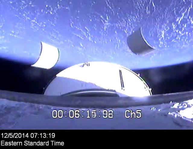
The service module panels separate during Orion's first flight test, Exploration Flight Test-1 (EFT-1), on December 5, 2014.
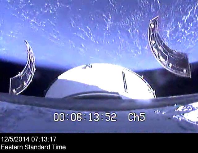
The service module panels separate during Orion's first flight test, Exploration Flight Test-1 (EFT-1), on December 5, 2014.
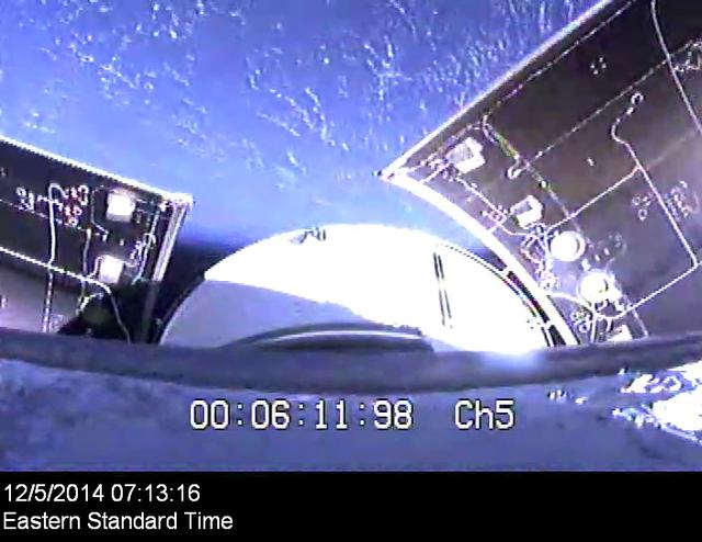
Orion's service module panels separate on its first flight test, Exploration Flight Test-1 (EFT-1), on December 5, 2014.
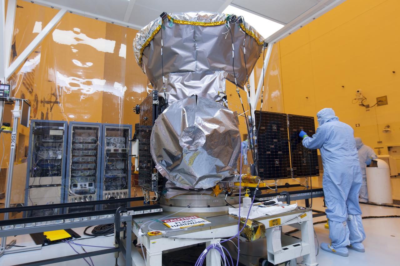
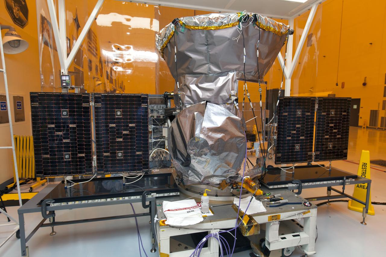
Inside the Payload Hazardous Servicing Facility at the NASA's Kennedy Space Center in Florida, the first of two solar panels is being deployed on the agency's Transiting Exoplanet Survey Satellite (TESS). The satellite is scheduled to launch atop a SpaceX Falcon 9 rocket from Space Launch Complex 40 at Cape Canaveral Air Force Station. TESS is the next step in NASA's search for planets outside our solar system, known as exoplanets. TESS is a NASA Astrophysics Explorer mission led and operated by MIT in Cambridge, Massachusetts, and managed by NASA’s Goddard Space Flight Center in Greenbelt, Maryland. Dr. George Ricker of MIT’s Kavli Institute for Astrophysics and Space Research serves as principal investigator for the mission. Additional partners include Orbital ATK, NASA’s Ames Research Center, the Harvard-Smithsonian Center for Astrophysics and the Space Telescope Science Institute. More than a dozen universities, research institutes and observatories worldwide are participants in the mission. NASA’s Launch Services Program is responsible for launch management.

Technicians dressed in clean room suits monitor the progress as both solar panels are deployed on NASA's Transiting Exoplanet Survey Satellite (TESS) inside the Payload Hazardous Servicing Facility (PHSF) at the agency's Kennedy Space Center in Florida. Inside the PHSF, the satellite is being processed and prepared for its flight. TESS is scheduled to launch atop a SpaceX Falcon 9 rocket from Space Launch Complex 40 at Cape Canaveral Air Force Station. The satellite is the next step in NASA's search for planets outside our solar system, known as exoplanets. TESS is a NASA Astrophysics Explorer mission led and operated by MIT in Cambridge, Massachusetts, and managed by NASA’s Goddard Space Flight Center in Greenbelt, Maryland. Dr. George Ricker of MIT’s Kavli Institute for Astrophysics and Space Research serves as principal investigator for the mission. Additional partners include Orbital ATK, NASA’s Ames Research Center, the Harvard-Smithsonian Center for Astrophysics and the Space Telescope Science Institute. More than a dozen universities, research institutes and observatories worldwide are participants in the mission. NASA’s Launch Services Program is responsible for launch management.
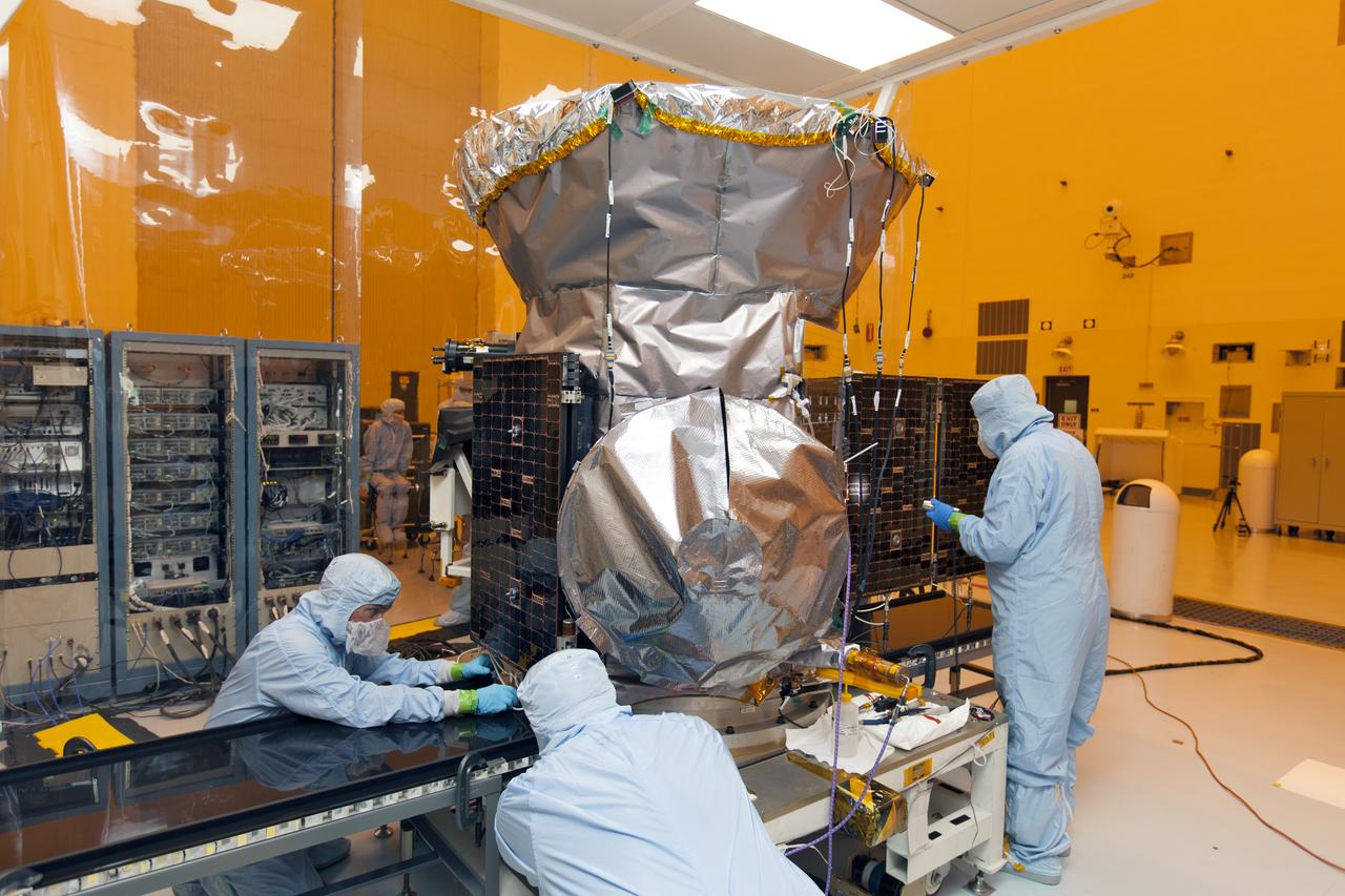
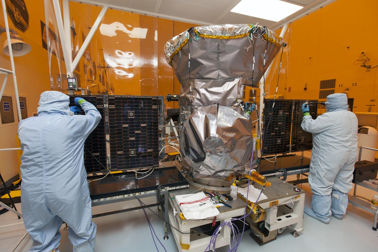
Inside the Payload Hazardous Servicing Facility at the NASA's Kennedy Space Center in Florida, one of the solar panels is being deployed on the agency's Transiting Exoplanet Survey Satellite (TESS). Technicians are preparing to deploy the second solar array. The satellite is scheduled to launch atop a SpaceX Falcon 9 rocket from Space Launch Complex 40 at Cape Canaveral Air Force Station. TESS is the next step in NASA's search for planets outside our solar system, known as exoplanets. TESS is a NASA Astrophysics Explorer mission led and operated by MIT in Cambridge, Massachusetts, and managed by NASA’s Goddard Space Flight Center in Greenbelt, Maryland. Dr. George Ricker of MIT’s Kavli Institute for Astrophysics and Space Research serves as principal investigator for the mission. Additional partners include Orbital ATK, NASA’s Ames Research Center, the Harvard-Smithsonian Center for Astrophysics and the Space Telescope Science Institute. More than a dozen universities, research institutes and observatories worldwide are participants in the mission. NASA’s Launch Services Program is responsible for launch management.
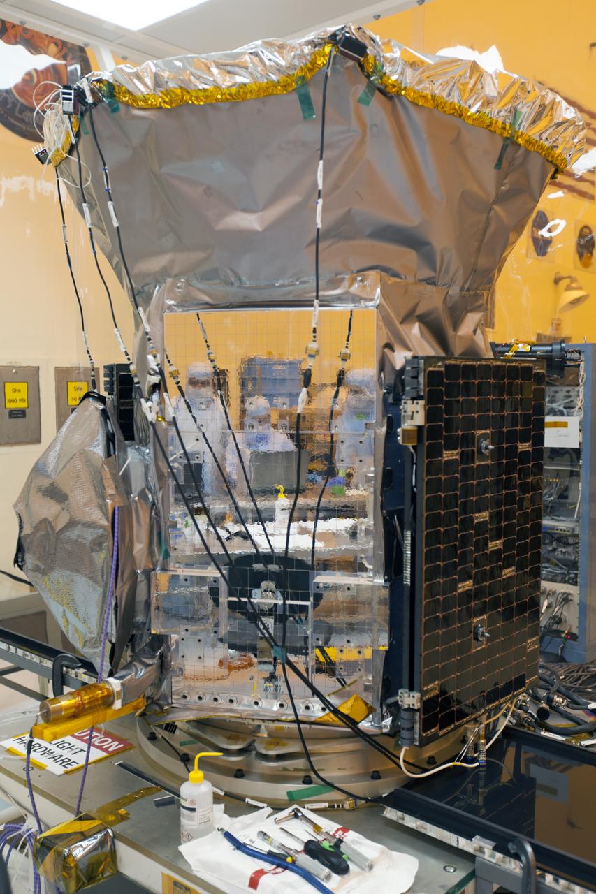
Preparations are underway for solar panel deployment on NASA's Transiting Exoplanet Survey Satellite (TESS) inside the Payload Hazardous Servicing Facility at the agency's Kennedy Space Center in Florida. TESS is scheduled to launch atop a SpaceX Falcon 9 rocket from Space Launch Complex 40 at Cape Canaveral Air Force Station. The satellite is the next step in NASA's search for planets outside our solar system, known as exoplanets. TESS is a NASA Astrophysics Explorer mission led and operated by MIT in Cambridge, Massachusetts, and managed by NASA’s Goddard Space Flight Center in Greenbelt, Maryland. Dr. George Ricker of MIT’s Kavli Institute for Astrophysics and Space Research serves as principal investigator for the mission. Additional partners include Orbital ATK, NASA’s Ames Research Center, the Harvard-Smithsonian Center for Astrophysics and the Space Telescope Science Institute. More than a dozen universities, research institutes and observatories worldwide are participants in the mission. NASA’s Launch Services Program is responsible for launch management.
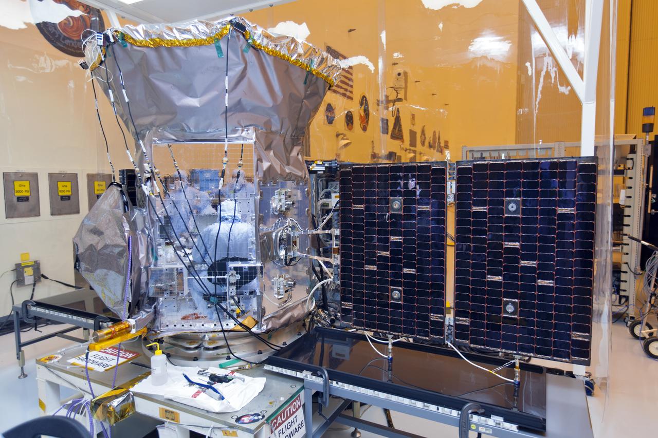
Inside the Payload Hazardous Servicing Facility at the NASA's Kennedy Space Center in Florida, both solar panels are deployed on the agency's Transiting Exoplanet Survey Satellite (TESS). The satellite is scheduled to launch atop a SpaceX Falcon 9 rocket from Space Launch Complex 40 at Cape Canaveral Air Force Station. TESS is the next step in NASA's search for planets outside our solar system, known as exoplanets. TESS is a NASA Astrophysics Explorer mission led and operated by MIT in Cambridge, Massachusetts, and managed by NASA’s Goddard Space Flight Center in Greenbelt, Maryland. Dr. George Ricker of MIT’s Kavli Institute for Astrophysics and Space Research serves as principal investigator for the mission. Additional partners include Orbital ATK, NASA’s Ames Research Center, the Harvard-Smithsonian Center for Astrophysics and the Space Telescope Science Institute. More than a dozen universities, research institutes and observatories worldwide are participants in the mission. NASA’s Launch Services Program is responsible for launch management.
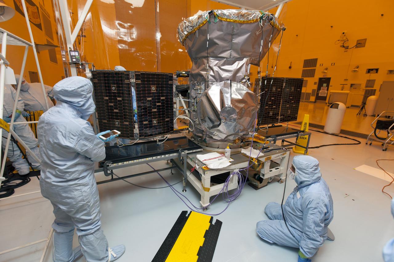
Technicians dressed in clean room suits monitor the progress as both solar panels are deployed on NASA's Transiting Exoplanet Survey Satellite (TESS) inside the Payload Hazardous Servicing Facility (PHSF) at the agency's Kennedy Space Center in Florida. Inside the PHSF, the satellite is being processed and prepared for its flight. TESS is scheduled to launch atop a SpaceX Falcon 9 rocket from Space Launch Complex 40 at Cape Canaveral Air Force Station. The satellite is the next step in NASA's search for planets outside our solar system, known as exoplanets. TESS is a NASA Astrophysics Explorer mission led and operated by MIT in Cambridge, Massachusetts, and managed by NASA’s Goddard Space Flight Center in Greenbelt, Maryland. Dr. George Ricker of MIT’s Kavli Institute for Astrophysics and Space Research serves as principal investigator for the mission. Additional partners include Orbital ATK, NASA’s Ames Research Center, the Harvard-Smithsonian Center for Astrophysics and the Space Telescope Science Institute. More than a dozen universities, research institutes and observatories worldwide are participants in the mission. NASA’s Launch Services Program is responsible for launch management.
Technicians dressed in clean room suits check the solar panels, which have been deployed, on NASA's Transiting Exoplanet Survey Satellite (TESS) inside the Payload Hazardous Servicing Facility (PHSF) at the agency's Kennedy Space Center in Florida. Inside the PHSF, the satellite is being processed and prepared for its flight. TESS is scheduled to launch atop a SpaceX Falcon 9 rocket from Space Launch Complex 40 at Cape Canaveral Air Force Station. The satellite is the next step in NASA's search for planets outside our solar system, known as exoplanets. TESS is a NASA Astrophysics Explorer mission led and operated by MIT in Cambridge, Massachusetts, and managed by NASA’s Goddard Space Flight Center in Greenbelt, Maryland. Dr. George Ricker of MIT’s Kavli Institute for Astrophysics and Space Research serves as principal investigator for the mission. Additional partners include Orbital ATK, NASA’s Ames Research Center, the Harvard-Smithsonian Center for Astrophysics and the Space Telescope Science Institute. More than a dozen universities, research institutes and observatories worldwide are participants in the mission. NASA’s Launch Services Program is responsible for launch management.
Inside the Payload Hazardous Servicing Facility at the NASA's Kennedy Space Center in Florida, the first of two solar panels is being deployed on the agency's Transiting Exoplanet Survey Satellite (TESS). The satellite is scheduled to launch atop a SpaceX Falcon 9 rocket from Space Launch Complex 40 at Cape Canaveral Air Force Station. TESS is the next step in NASA's search for planets outside our solar system, known as exoplanets. TESS is a NASA Astrophysics Explorer mission led and operated by MIT in Cambridge, Massachusetts, and managed by NASA’s Goddard Space Flight Center in Greenbelt, Maryland. Dr. George Ricker of MIT’s Kavli Institute for Astrophysics and Space Research serves as principal investigator for the mission. Additional partners include Orbital ATK, NASA’s Ames Research Center, the Harvard-Smithsonian Center for Astrophysics and the Space Telescope Science Institute. More than a dozen universities, research institutes and observatories worldwide are participants in the mission. NASA’s Launch Services Program is responsible for launch management.
Thermal Evaluaion of X-37 Body Flap Sea test in Panel Test Facility PTF-115 with (l) Duoc Tran, Boeing Test engineer and (r) Vincent Meglio, NASA lead Engineering Technician / Operator
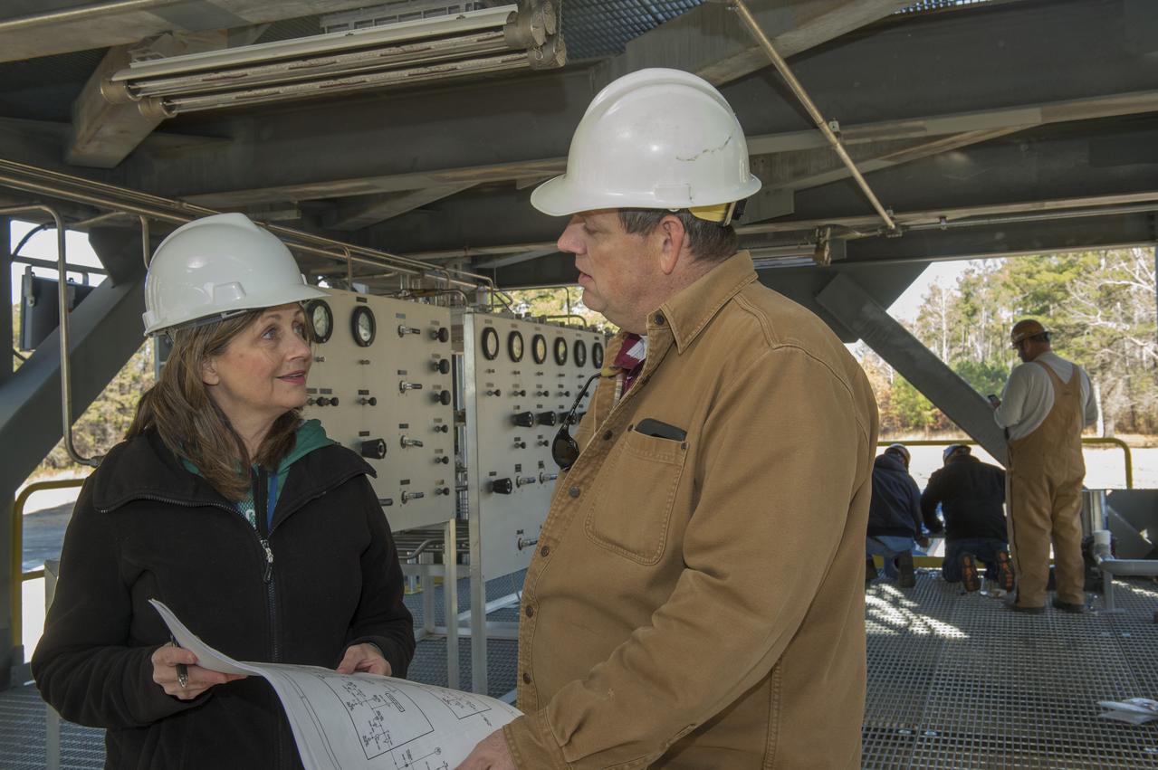
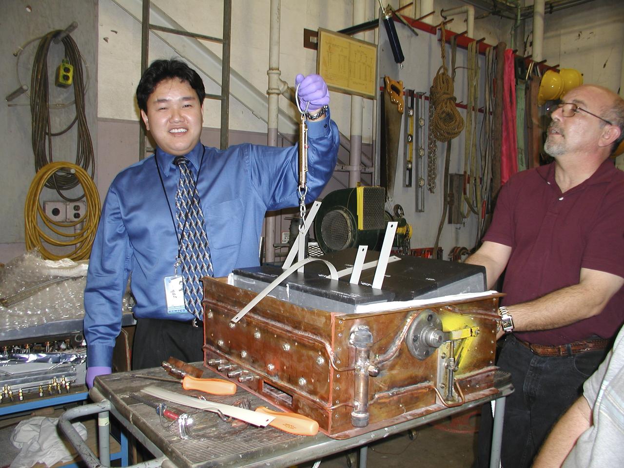
TARA MARSHALL, LEFT, A MARSHALL ENGINEER, TALKS ABOUT THE INSTALLATION OF A PRESSURIZATION CONTROL PANEL AT TEST STAND 4693 WITH MIKE NICHOLS, LEAD TEST ENGINEER FOR THE SPACE LAUNCH SYSTEM LIQUID HYDROGEN TANK STRUCTURAL TEST ARTICLE.
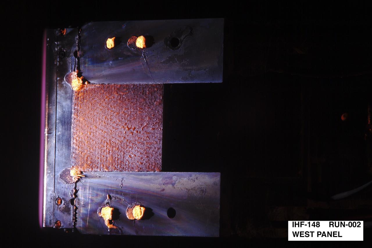
NEXT GENERATION THERMAL PROTECTION MATERIALS TESTING IN INTERACTIVE HEATING FACILITY; IHF-148 Run 002 West Panel
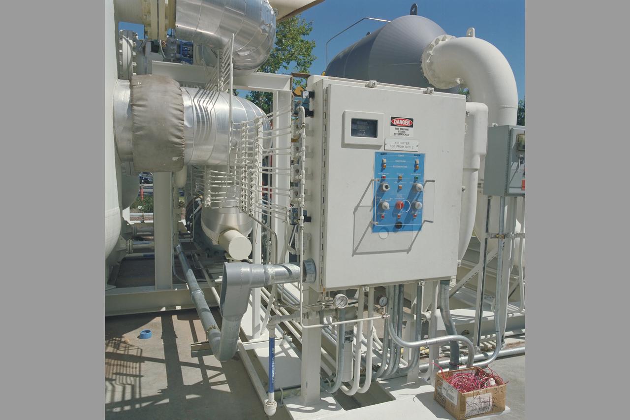
N-206 12ft W.T. ADTE Project (Aeronautics Design and Test Environment) 3' conduit to dry air control panel
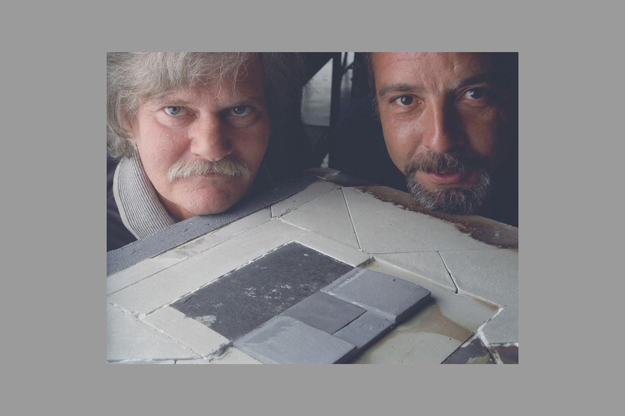
KENNEDY SPACE CENTER, FLA. -- In the Orbiter Processing Facility, an employee from The Boeing Co., Huntington Beach, Calif., installs a strain gauge on a test panel prior to installation of Thermal Protection System tile on the panel. The test panel and sections of Space Shuttle orbiter Enterprise (OV-101) will be transferred to the Southwest Research Institute for testing after the tile installation is complete. The testing has been requested by the Columbia Accident Investigation Board. Sections of Enterprise were borrowed from the Smithsonian Institution's Air and Space Museum where the orbiter is being stored at the Washington Dulles International Airport. Enterprise was the first orbiter built in the Shuttle fleet and was used to conduct the Approach and Landing Test Program before the first powered Shuttle flight.

KENNEDY SPACE CENTER, FLA. -- In the Orbiter Processing Facility, employees from The Boeing Co., Huntington Beach, Calif., install a strain gauge on a test panel prior to installation of Thermal Protection System tile on the panel. The test panel and sections of Space Shuttle orbiter Enterprise (OV-101) will be transferred to the Southwest Research Institute for testing after the tile installation is complete. The testing has been requested by the Columbia Accident Investigation Board. Sections of Enterprise were borrowed from the Smithsonian Institution's Air and Space Museum where the orbiter is being stored at the Washington Dulles International Airport. Enterprise was the first orbiter built in the Shuttle fleet and was used to conduct the Approach and Landing Test Program before the first powered Shuttle flight.
KENNEDY SPACE CENTER, FLA. -- In the Orbiter Processing Facility, United Space Alliance employee Mike Cote installs Thermal Protection System tiles on a test panel. The test panel and sections of Space Shuttle orbiter Enterprise (OV-101) will be transferred to the Southwest Research Institute for testing after the tile installation is complete. The testing has been requested by the Columbia Accident Investigation Board. Sections of Enterprise were borrowed from the Smithsonian Institution's Air and Space Museum where the orbiter is being stored at the Washington Dulles International Airport. Enterprise was the first orbiter built in the Shuttle fleet and was used to conduct the Approach and Landing Test Program before the first powered Shuttle flight.
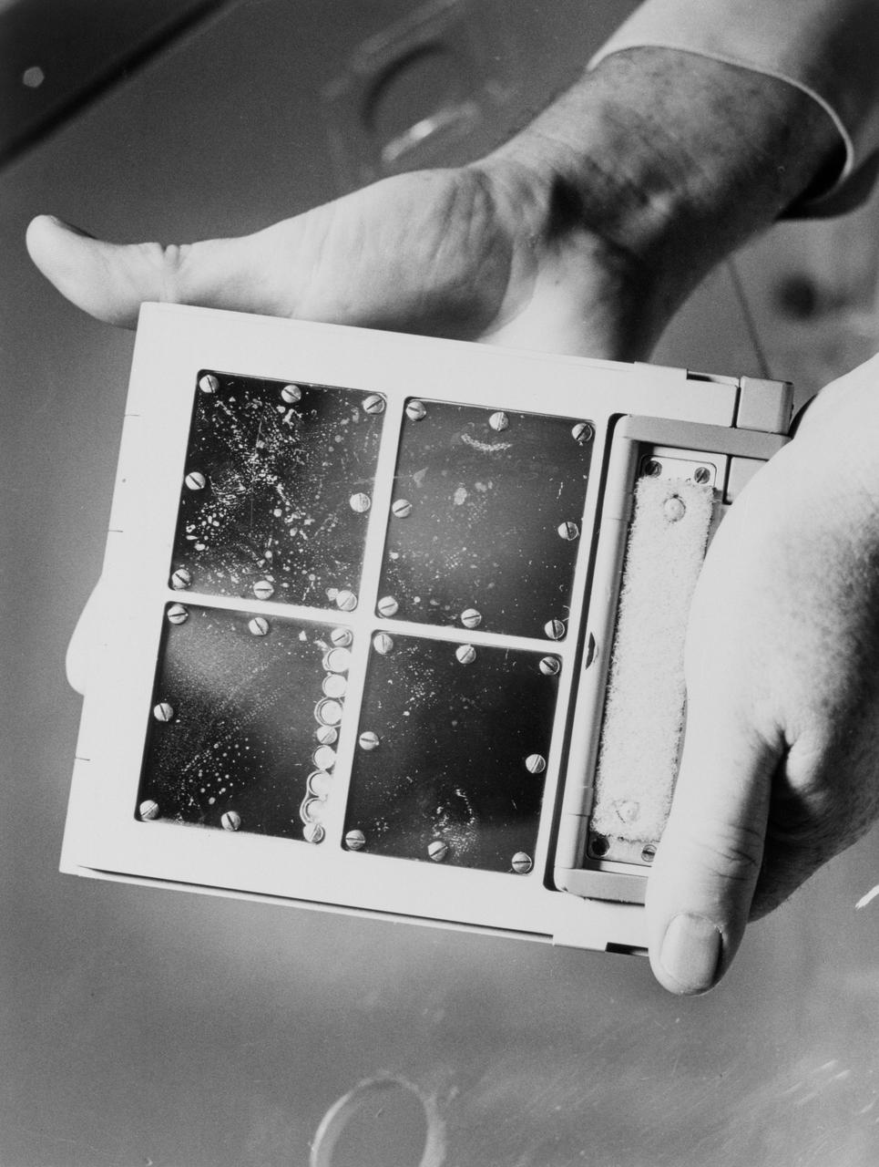
S66-44886 (1 Aug. 1966) --- Four panels of experiment S-10 carried on the Agena Target Vehicle launched for the Gemini-8 mission. This package of test panels was retrieved from the Gemini-8 Agena by astronaut Michael Collins during the Gemini-10 mission. Experimenters expected micrometeorites to bombard the panels during their stay in space. Photo credit: NASA
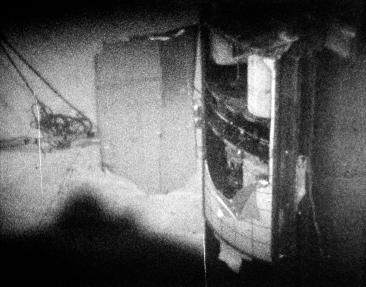
S70-41983 (June 1970) --- Second photograph in sequence of three of panel separation test at Langley Research Center. The test was part of the Apollo 13 post flight investigation of the Service Module explosion incident. Photo credit: NASA
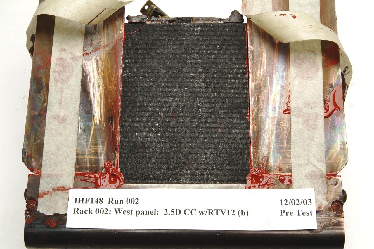
NEXT GENERATION THERMAL PROTECTION MATERIALS TESTING IN INTERACTIVE HEATING FACILITY; IHF-148 Run 002: Rack 002 West Panel: 2.5D CC W/RTVIC (b) 12/2/03 pre- test
Overview of the solar panels test of the Advanced Composite Solar Sail System (ACS3) spacecraft in the Ames Integration Facility in N213 room 104.
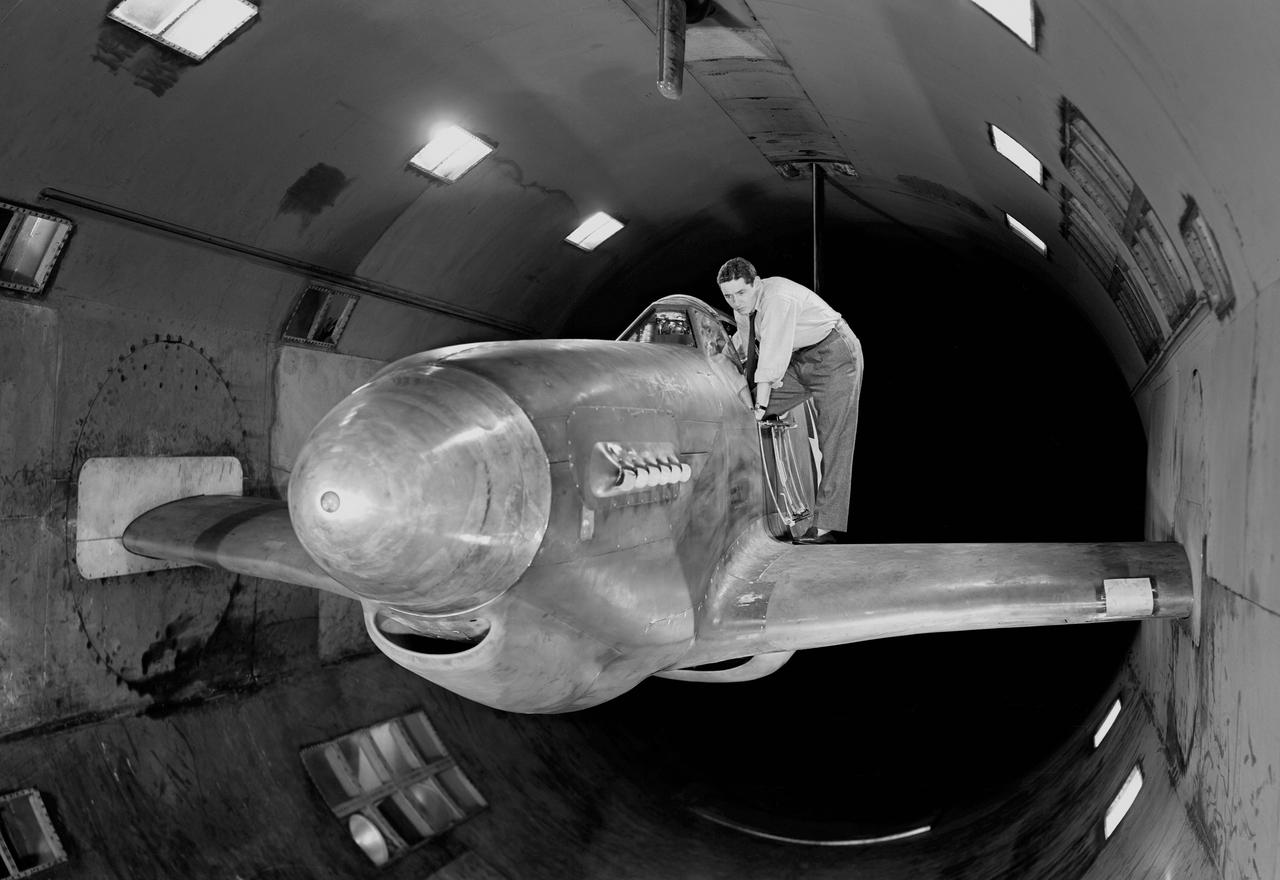
NACA Photographer - North American XP-51B Airplane with outer wing panels removed and ready for testing in Ames 16 foot wind tunnel.
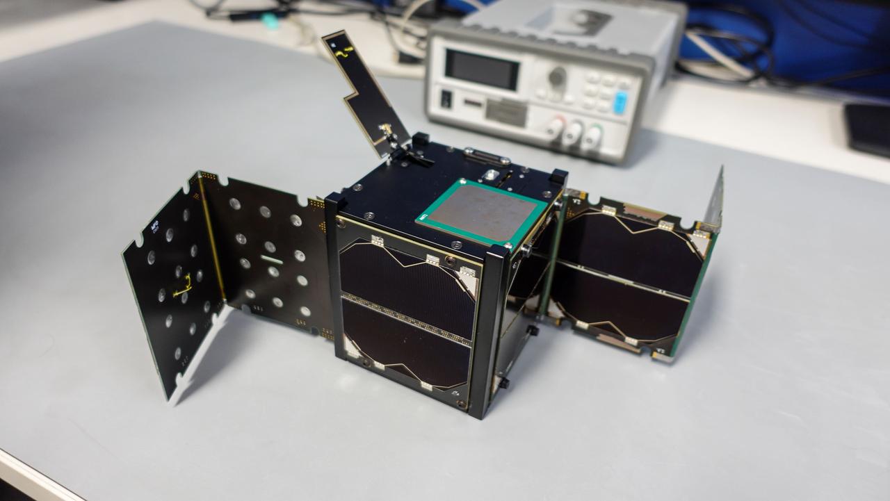
jsc2024e043923 (4/9/2024) -- Binar-3 (EM) undergoing deployment testing of the radio-communication system and the solar panels...Image Credit: Binar Space Program.
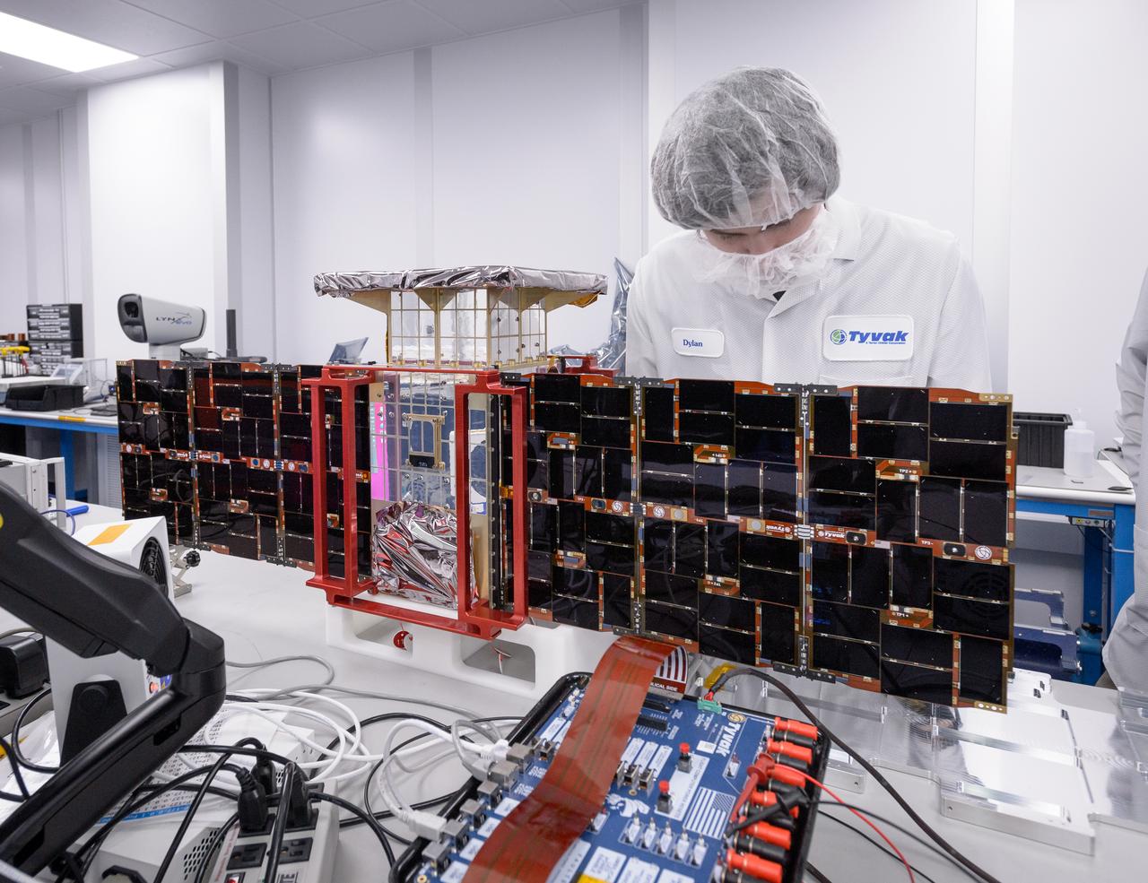
Dylan Schmidt, CAPSTONE assembly integration and test lead, installs solar panels onto the CAPSTONE spacecraft at Tyvak Nano-Satellite Systems, Inc., in Irvine, California.
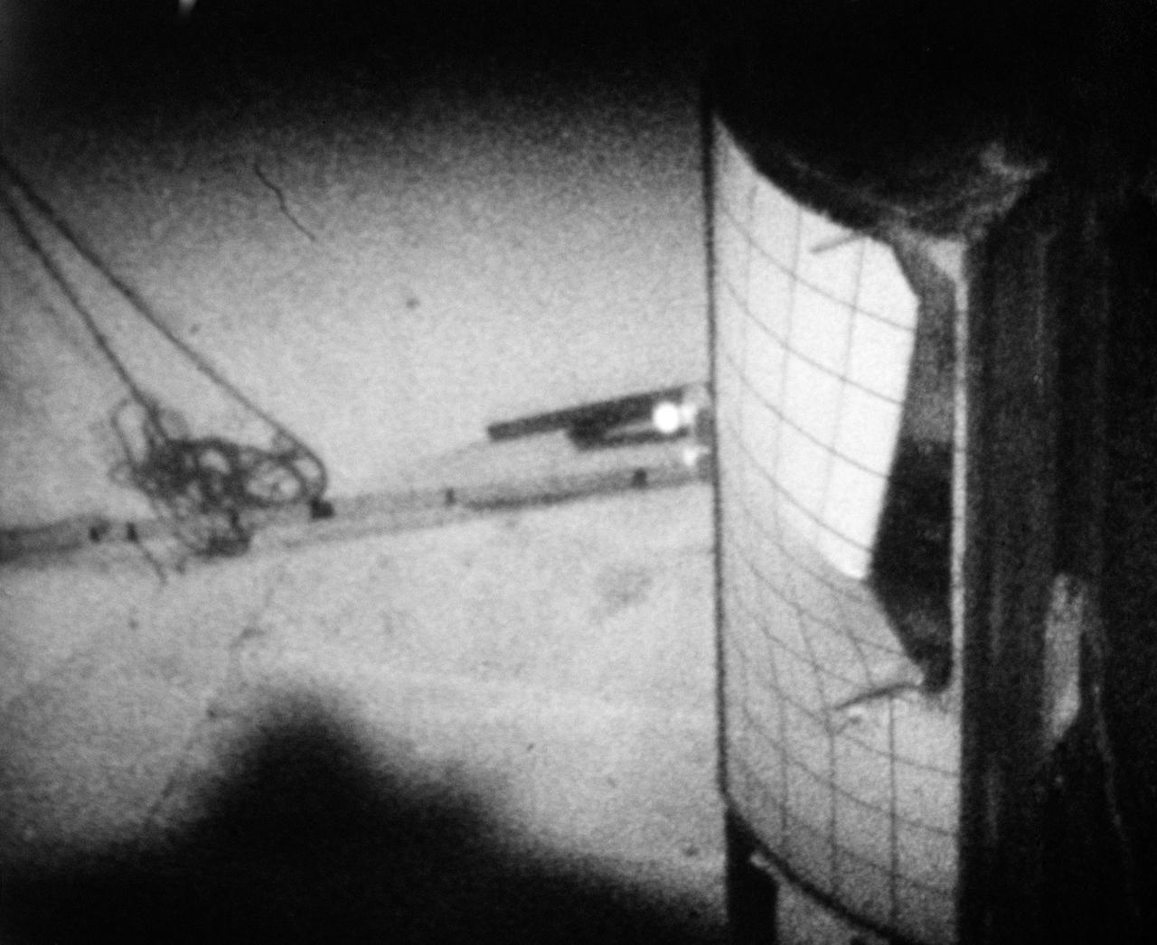
S70-41982 (June 1970) --- Sequence photo from 16mm motion picture film of test at National Aeronautics and Space Administration's Langley Research Center which seeks to determine mechanism by which Apollo 13 panel was separated from the Service Module. Test used a 1/2 scale model with a honeycomb sandwich panel and was conducted in a vacuum. (First of three photographs in sequence). Photo credit: NASA
KENNEDY SPACE CENTER, FLA. - Workers in the Orbiter Processing Facility check the placement of the Reinforced Carbon-Carbon (RCC) chin panel on Discovery. . The chin panel is the smile-shaped section of RCC directly below the nose cap that provides a thermal barrier during re-entry. The nose cap, with chin panel, was removed from the vehicle in the summer of 2003 and returned to the vendor, where it underwent numerous forms of Non-Destructive Evaluation. These tests included X-ray, ultrasound and eddy current to ensure its structural integrity prior to reinstallation. Discovery is designated as the Return to Flight vehicle for mission STS-114, no earlier than March 2005.
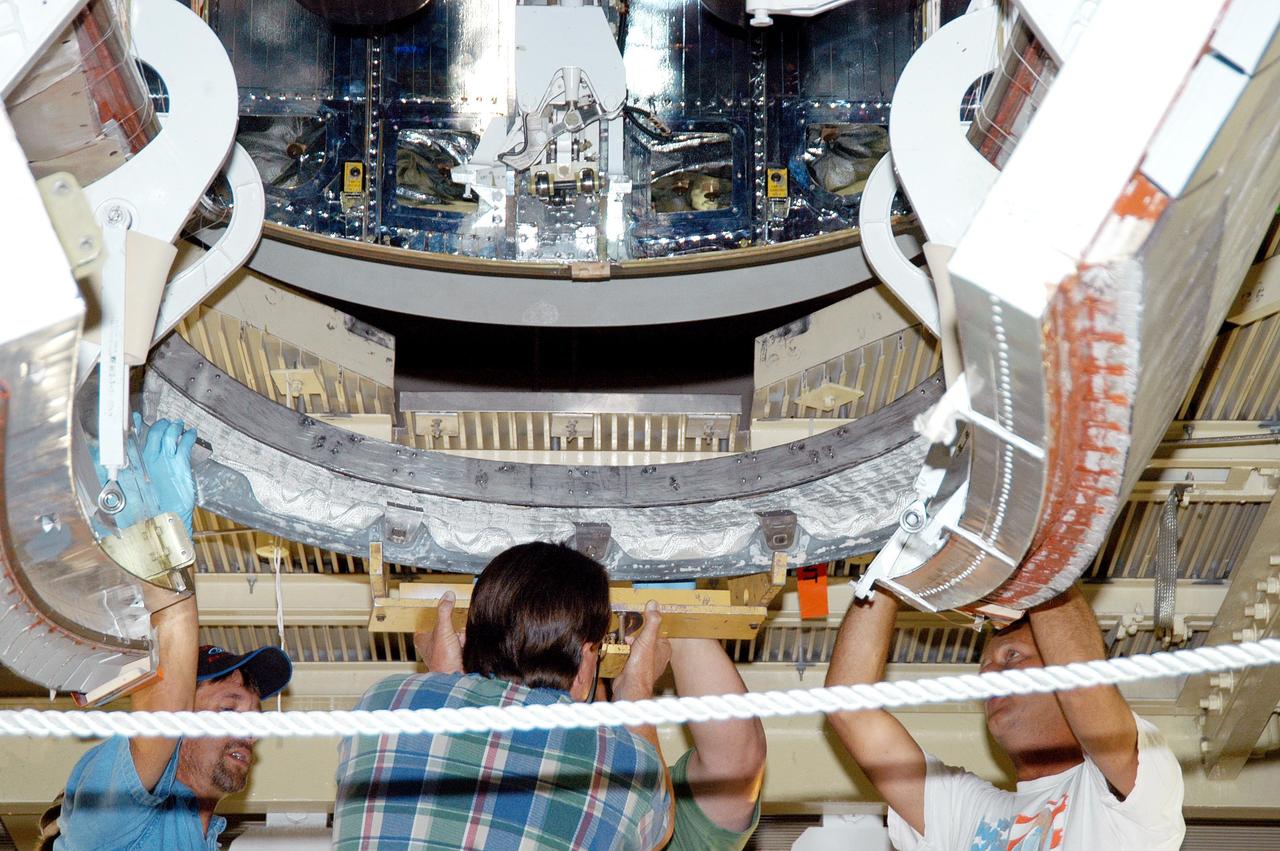
KENNEDY SPACE CENTER, FLA. - Workers in the Orbiter Processing Facility lift the Reinforced Carbon-Carbon (RCC) chin panel into place on Discovery. The chin panel is the smile-shaped section of RCC directly below the nose cap that provides a thermal barrier during re-entry. The nose cap, with chin panel, was removed from the vehicle in the summer of 2003 and returned to the vendor, where it underwent numerous forms of Non-Destructive Evaluation. These tests included X-ray, ultrasound and eddy current to ensure its structural integrity prior to reinstallation. Discovery is designated as the Return to Flight vehicle for mission STS-114, no earlier than March 2005.
KENNEDY SPACE CENTER, FLA. - - Workers in the Orbiter Processing Facility complete the installation of the Reinforced Carbon-Carbon panel on Discovery. The chin panel is the smile-shaped section of RCC directly below the nose cap that provides a thermal barrier during re-entry. The nose cap, with chin panel, was removed from the vehicle in the summer of 2003 and returned to the vendor, where it underwent numerous forms of Non-Destructive Evaluation. These tests included X-ray, ultrasound and eddy current to ensure its structural integrity prior to reinstallation. Discovery is designated as the Return to Flight vehicle for mission STS-114, no earlier than March 2005.
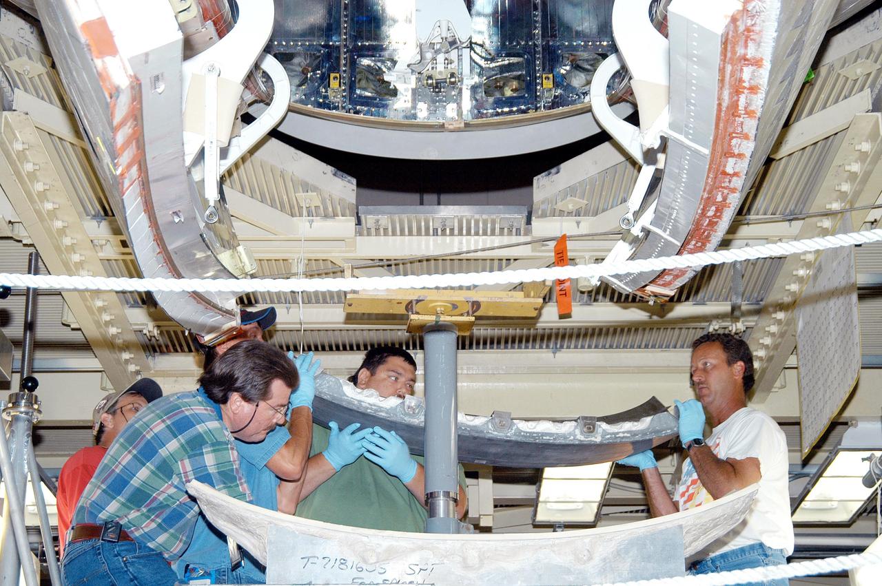
KENNEDY SPACE CENTER, FLA. - Workers in the Orbiter Processing Facility lift the Reinforced Carbon-Carbon (RCC) chin panel to install on Discovery. The chin panel is the smile-shaped section of RCC directly below the nose cap that provides a thermal barrier during re-entry. The nose cap, with chin panel, was removed from the vehicle in the summer of 2003 and returned to the vendor, where it underwent numerous forms of Non-Destructive Evaluation. These tests included X-ray, ultrasound and eddy current to ensure its structural integrity prior to reinstallation. Discovery is designated as the Return to Flight vehicle for mission STS-114, no earlier than March 2005.

KENNEDY SPACE CENTER, FLA. - Workers in the Orbiter Processing Facility prepare the Reinforced Carbon-Carbon (RCC) chin panel to install on Discovery. The chin panel is the smile-shaped section of RCC directly below the nose cap that provides a thermal barrier during re-entry. The nose cap, with chin panel, was removed from the vehicle in the summer of 2003 and returned to the vendor, where it underwent numerous forms of Non-Destructive Evaluation. These tests included X-ray, ultrasound and eddy current to ensure its structural integrity prior to reinstallation. Discovery is designated as the Return to Flight vehicle for mission STS-114, no earlier than March 2005.
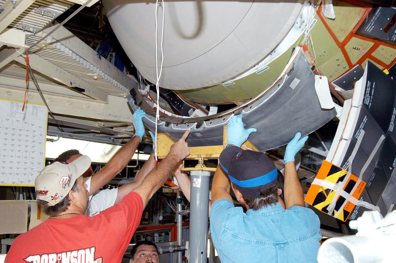
KENNEDY SPACE CENTER, FLA. - - Workers in the Orbiter Processing Facility check the placement of the Reinforced Carbon-Carbon chin panel on Discovery. The chin panel is the smile-shaped section of RCC directly below the nose cap that provides a thermal barrier during re-entry. The nose cap, with chin panel, was removed from the vehicle in the summer of 2003 and returned to the vendor, where it underwent numerous forms of Non-Destructive Evaluation. These tests included X-ray, ultrasound and eddy current to ensure its structural integrity prior to reinstallation. Discovery is designated as the Return to Flight vehicle for mission STS-114, no earlier than March 2005.
Surface Protected Flexible Insulation (SPFI) Blanket in Panel Test Facililty PTF-78 V. Meglio and D Threoux are shown here with the Ames made calibration model
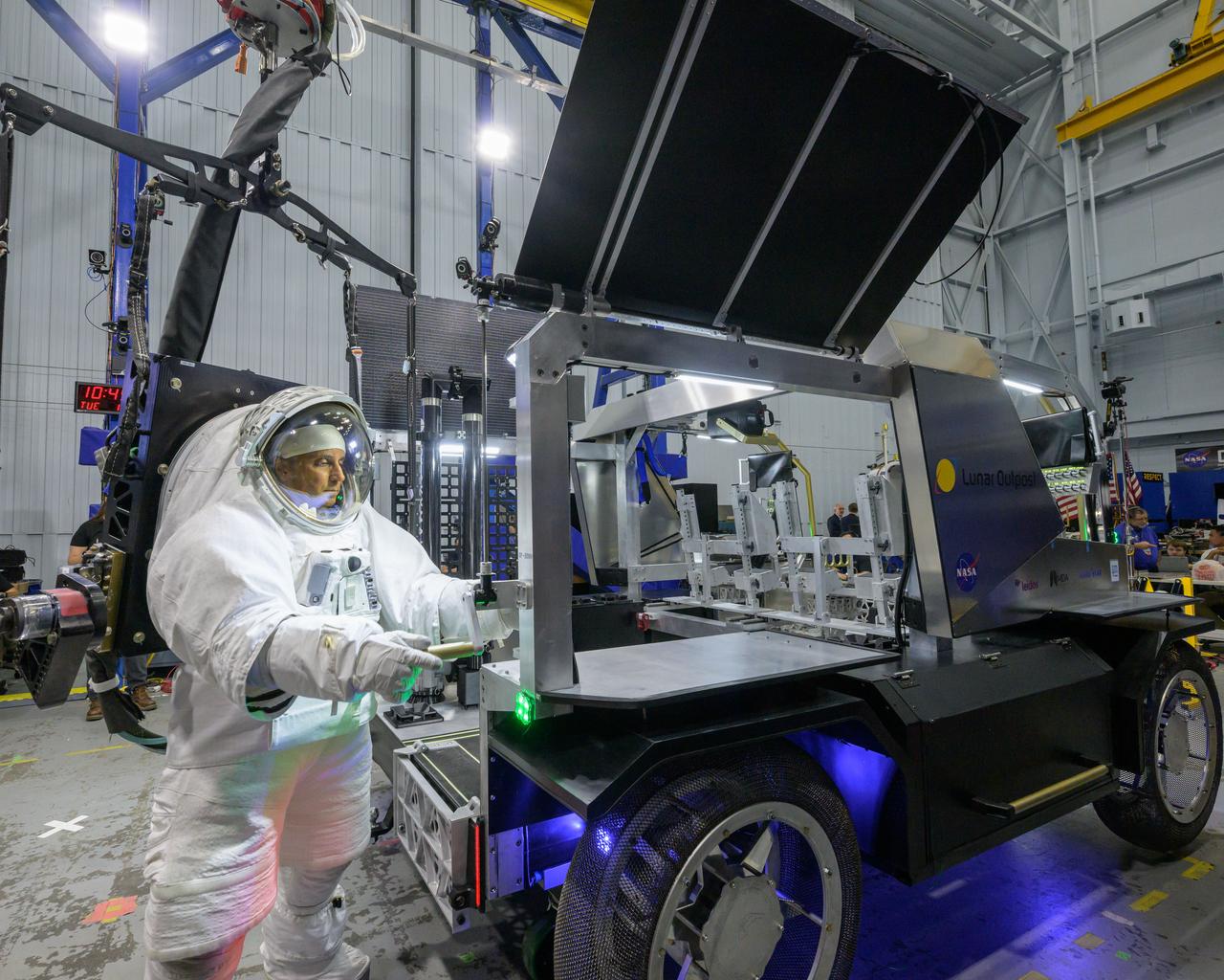
NASA astronaut Joe Acaba raises the solar array panel on Lunar Outpost’s Eagle lunar terrain vehicle during testing at NASA’s Johnson Space Center. Image Credit: NASA/Robert Markowitz
S70-41985 (15 June 1970) --- The third photograph in sequence of three showing panel separation test at Langley Research Center (LRC). The test was part of the Apollo 13 post flight investigation of the Service Module explosion incident. Photo credit: NASA
Rebecca Rogers, systems engineer, center, Lachlan Moore, systems integration engineer, right, and Dylan Schmidt, CAPSTONE assembly integration and test lead, background, perform a solar panel string voltage test of the CAPSTONE spacecraft at Tyvak Nano-Satellite Systems, Inc., in Irvine, California.

Engineers at NASA's Jet Propulsion Laboratory in Southern California examine one of Psyche's solar arrays during a deployment test in the Lab's High Bay 2 clean room in late February 2022. The twin arrays are together about 800 square feet (75 square meters) – the largest ever deployed at JPL. Part of a solar electric propulsion system provided by Maxar Technologies, they will power the spacecraft on its 1.5 billion-mile (2.4 billion-kilometer) journey to the large, metal-rich asteroid Psyche. Only the three center panels on each five-panel, cross-shaped array can be deployed at JPL due to the limitations of the gravity-offload fixture and the opposing direction of rotation of the cross panels. Deployment of the two cross panels was previously performed at Maxar with different equipment. After further spacecraft testing is completed at JPL, the arrays will be removed and returned to Maxar in order to repeat the cross-panel deployments, make any final repairs to the solar cells, and test overall performance. The arrays then get shipped from Maxar to NASA's Kennedy Space Center in Florida, where they will be reintegrated onto the spacecraft in preparation for launch in August 2022. About an hour after launch, Psyche will deploy the arrays sequentially, first unfolding the three lengthwise center panels, then the two cross panels on one wing before repeating the process with the other wing. Each array takes about 7 ½ minutes to unfurl and latch into place. Each array is 37.1 feet (11.3 meters) long and 24 feet (7.3 meters) wide when fully deployed. With arrays deployed on either side of the chassis, the spacecraft is about the size of a singles tennis court: 81 feet long (24.7 meters) and 24 feet (7.3 meters) wide. https://photojournal.jpl.nasa.gov/catalog/PIA25134
Engineers at NASA's Jet Propulsion Laboratory in Southern California successfully deployed a solar array installed on the agency's Psyche spacecraft. It was one of two deployed during testing in the Lab's High Bay 2 clean room in late February 2022. The twin arrays are together about 800 square feet (75 square meters) – the largest ever deployed at JPL. Part of a solar electric propulsion system provided by Maxar Technologies, they will power the spacecraft on its 1.5 billion-mile (2.4 billion-kilometer) journey to the large, metal-rich asteroid Psyche. Only the three center panels on each five-panel, cross-shaped array can be deployed at JPL due to the limitations of the gravity-offload fixture and the opposing direction of rotation of the cross panels. Deployment of the two cross panels was previously performed at Maxar with different equipment. After further spacecraft testing is completed at JPL, the arrays will be removed and returned to Maxar in order to repeat the cross-panel deployments, make any final repairs to the solar cells, and test overall performance. The arrays then get shipped from Maxar to NASA's Kennedy Space Center in Florida, where they will be reintegrated onto the spacecraft in preparation for launch in August 2022. About an hour after launch, Psyche will deploy the arrays sequentially, first unfolding the three lengthwise center panels, then the two cross panels on one wing before repeating the process with the other wing. Each array takes about 7 ½ minutes to unfurl and latch into place. Each array is 37.1 feet (11.3 meters) long and 24 feet (7.3 meters) wide when fully deployed. With arrays deployed on either side of the chassis, the spacecraft is about the size of a singles tennis court: 81 feet long (24.7 meters) and 24 feet (7.3 meters) wide. https://photojournal.jpl.nasa.gov/catalog/PIA25135
Engineers at NASA's Jet Propulsion Laboratory in Southern California examine one of Psyche's stowed solar arrays prior to a deployment test in the Lab's High Bay 2 clean room in late February 2022. The twin arrays are together about 800 square feet (75 square meters) – the largest ever deployed at JPL. Part of a solar electric propulsion system provided by Maxar Technologies, they will power the spacecraft on its 1.5 billion-mile (2.4 billion-kilometer) journey to the large, metal-rich asteroid Psyche. Only the three center panels on each five-panel, cross-shaped array can be deployed at JPL due to the limitations of the gravity-offload fixture and the opposing direction of rotation of the cross panels. Deployment of the two cross panels was previously performed at Maxar with different equipment. After further spacecraft testing is completed at JPL, the arrays will be removed and returned to Maxar in order to repeat the cross-panel deployments, make any final repairs to the solar cells, and test overall performance. The arrays then get shipped from Maxar to NASA's Kennedy Space Center in Florida, where they will be reintegrated onto the spacecraft in preparation for launch in August 2022. About an hour after launch, Psyche will deploy the arrays sequentially, first unfolding the three lengthwise center panels, then the two cross panels on one wing before repeating the process with the other wing. Each array takes about 7 ½ minutes to unfurl and latch into place. Each array is 37.1 feet (11.3 meters) long and 24 feet (7.3 meters) wide when fully deployed. With arrays deployed on either side of the chassis, the spacecraft is about the size of a singles tennis court: 81 feet long (24.7 meters) and 24 feet (7.3 meters) wide. https://photojournal.jpl.nasa.gov/catalog/PIA25132

CAPE CANAVERAL, Fla. - The first set of two Ogive panels for the Orion Launch Abort System was uncrated inside the Launch Abort System Facility, or LASF, at NASA’s Kennedy Space Center in Florida. One of the panels has been secured on a stand at the far end of the facility while technicians prepare to lift the second panel to move it to the storage stand. During processing, the panels will be secured around the Orion crew module and attached to the Launch Abort System. Orion is the exploration spacecraft designed to carry astronauts to destinations not yet explored by humans, including an asteroid and Mars. It will have emergency abort capability, sustain the crew during space travel and provide safe re-entry from deep space return velocities. The first unpiloted test flight of Orion is scheduled to launch in 2014 atop a Delta IV rocket and in 2017 on NASA’s Space Launch System rocket. For more information, visit www.nasa.gov/orion. Photo credit: Dan Casper
CAPE CANAVERAL, Fla. - The first set of two Ogive panels for the Orion Launch Abort System was uncrated inside the Launch Abort System Facility, or LASF, at NASA’s Kennedy Space Center in Florida. The second panel is being lifted by crane and technicians are monitoring the progress as it is being moved to join the first panel on the storage stand. During processing, the panels will be secured around the Orion crew module and attached to the Launch Abort System. Orion is the exploration spacecraft designed to carry astronauts to destinations not yet explored by humans, including an asteroid and Mars. It will have emergency abort capability, sustain the crew during space travel and provide safe re-entry from deep space return velocities. The first unpiloted test flight of Orion is scheduled to launch in 2014 atop a Delta IV rocket and in 2017 on NASA’s Space Launch System rocket. For more information, visit www.nasa.gov/orion. Photo credit: Dan Casper
CAPE CANAVERAL, Fla. - The first set of two Ogive panels for the Orion Launch Abort System was uncrated inside the Launch Abort System Facility, or LASF, at NASA’s Kennedy Space Center in Florida. One of the panels has been secured on a stand at the far end of the facility. Technicians assist as a crane is attached to the second panel for lifting and moving to the storage stand. During processing, the panels will be secured around the Orion crew module and attached to the Launch Abort System. Orion is the exploration spacecraft designed to carry astronauts to destinations not yet explored by humans, including an asteroid and Mars. It will have emergency abort capability, sustain the crew during space travel and provide safe re-entry from deep space return velocities. The first unpiloted test flight of Orion is scheduled to launch in 2014 atop a Delta IV rocket and in 2017 on NASA’s Space Launch System rocket. For more information, visit www.nasa.gov/orion. Photo credit: Dan Casper
CAPE CANAVERAL, Fla. - The first set of two Ogive panels for the Orion Launch Abort System was uncrated inside the Launch Abort System Facility, or LASF, at NASA’s Kennedy Space Center in Florida. One of the panels has been secured on a stand at the far end of the facility. Technicians assist as a crane is attached to the second panel for lifting and moving to the storage stand. During processing, the panels will be secured around the Orion crew module and attached to the Launch Abort System. Orion is the exploration spacecraft designed to carry astronauts to destinations not yet explored by humans, including an asteroid and Mars. It will have emergency abort capability, sustain the crew during space travel and provide safe re-entry from deep space return velocities. The first unpiloted test flight of Orion is scheduled to launch in 2014 atop a Delta IV rocket and in 2017 on NASA’s Space Launch System rocket. For more information, visit www.nasa.gov/orion. Photo credit: Dan Casper
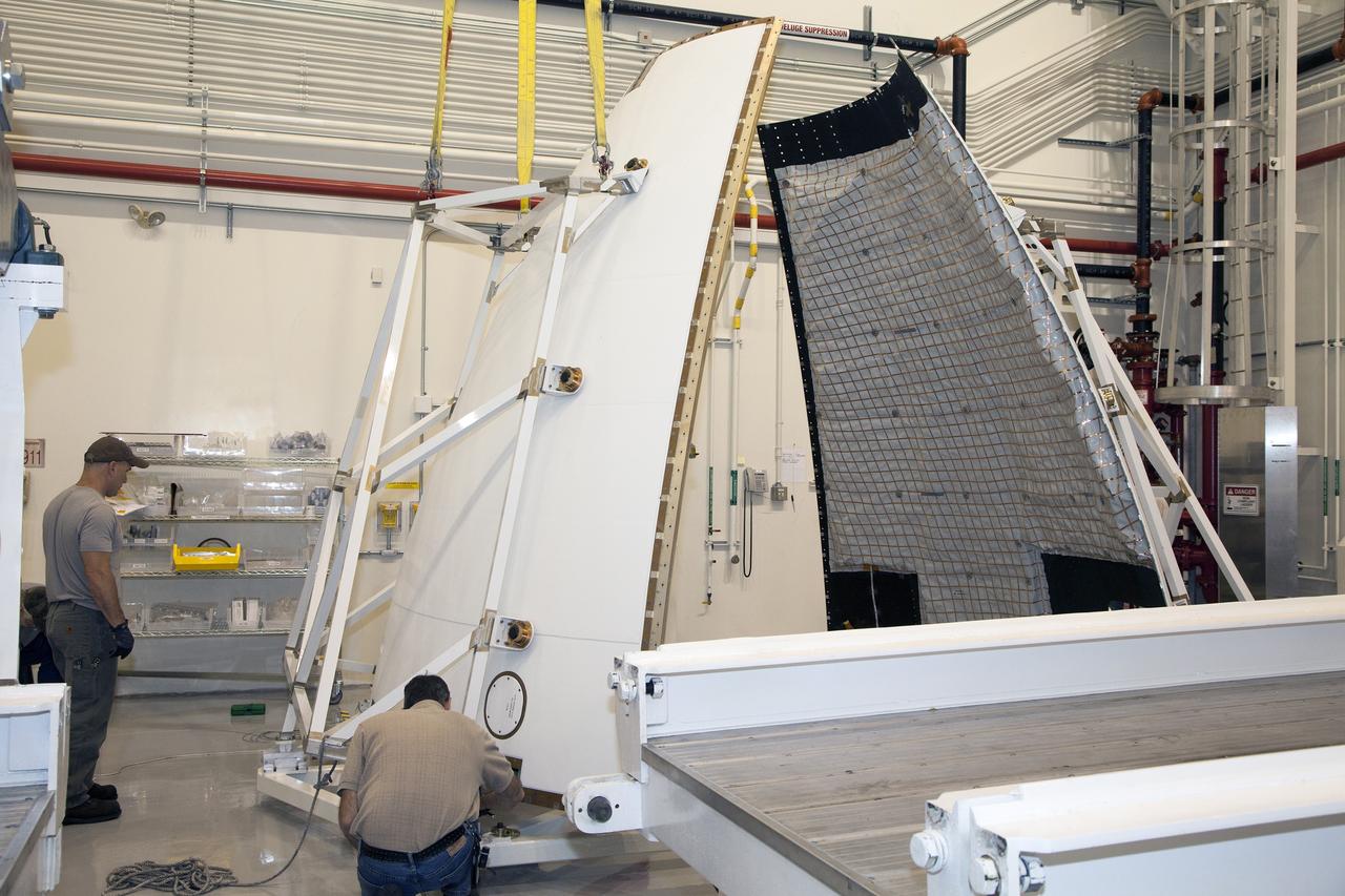
CAPE CANAVERAL, Fla. - The first set of two Ogive panels for the Orion Launch Abort System was uncrated inside the Launch Abort System Facility, or LASF, at NASA’s Kennedy Space Center in Florida. The first panel is secured on a storage stand while the second panel is being lowered by crane onto the storage stand. During processing, the panels will be secured around the Orion crew module and attached to the Launch Abort System. Orion is the exploration spacecraft designed to carry astronauts to destinations not yet explored by humans, including an asteroid and Mars. It will have emergency abort capability, sustain the crew during space travel and provide safe re-entry from deep space return velocities. The first unpiloted test flight of Orion is scheduled to launch in 2014 atop a Delta IV rocket and in 2017 on NASA’s Space Launch System rocket. For more information, visit www.nasa.gov/orion. Photo credit: Dan Casper
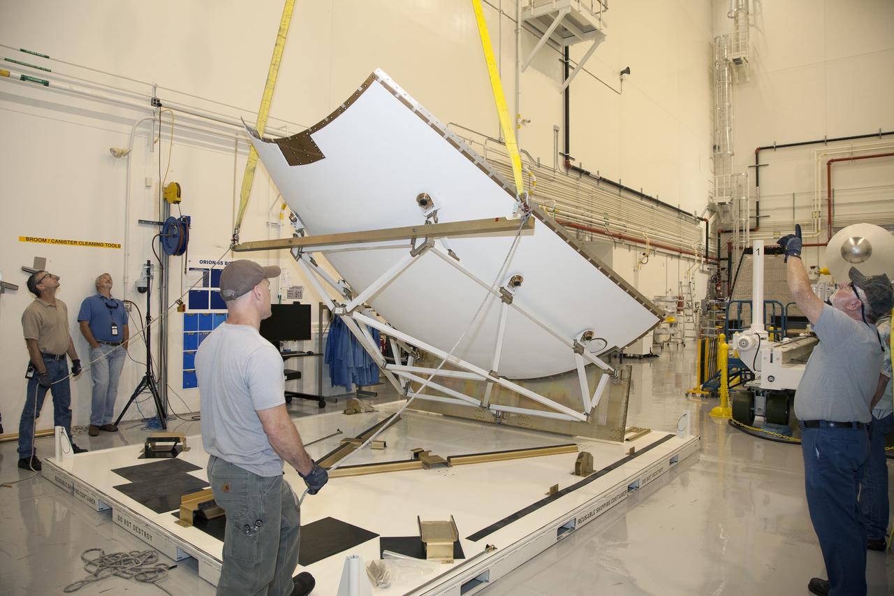
CAPE CANAVERAL, Fla. - The first set of two Ogive panels for the Orion Launch Abort System was uncrated inside the Launch Abort System Facility, or LASF, at NASA’s Kennedy Space Center in Florida. One of the panels has been secured on a stand at the far end of the facility. Technicians monitor the progress as a crane lifts the second panel to move it to the storage stand. During processing, the panels will be secured around the Orion crew module and attached to the Launch Abort System. Orion is the exploration spacecraft designed to carry astronauts to destinations not yet explored by humans, including an asteroid and Mars. It will have emergency abort capability, sustain the crew during space travel and provide safe re-entry from deep space return velocities. The first unpiloted test flight of Orion is scheduled to launch in 2014 atop a Delta IV rocket and in 2017 on NASA’s Space Launch System rocket. For more information, visit www.nasa.gov/orion. Photo credit: Dan Casper
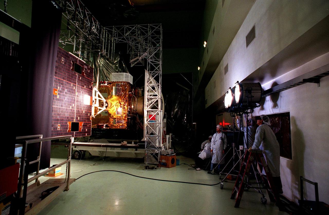
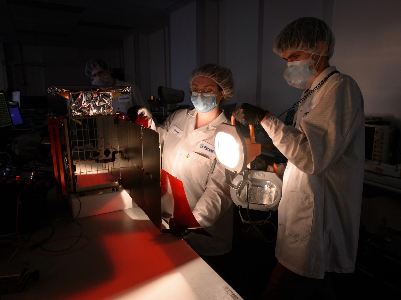
Workers (right) at Astrotech, Titusville, Fla., arrange the lights for an illumination test on the solar panel of the <a href="http://www-pao.ksc.nasa.gov/kscpao/captions/subjects/goes-l.htm">GOES-L</a> weather satellite. The test is verifying the circuitry on the panel. The satellite is to be launched from Cape Canaveral Air Station aboard an Atlas II rocket in late March. The GOES-L is the fourth of a new advanced series of geostationary weather satellites for the National Oceanic and Atmospheric Administration. It is a three-axis inertially stabilized spacecraft that will provide pictures and perform atmospheric sounding at the same time. Once launched, the satellite, to be designated GOES-11, will undergo checkout and provide backup capabilities for the existing, aging GOES East weather satellite
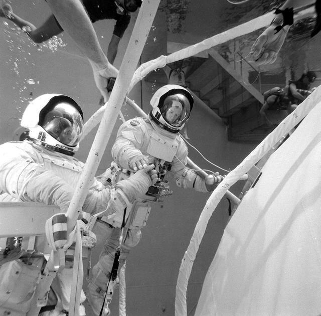
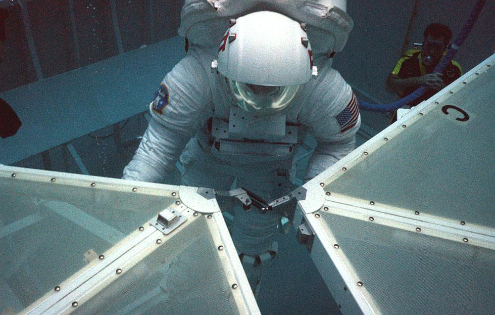
This photograph was taken during testing of an emergency procedure to free jammed solar array panels on the Skylab workshop. A metal strap became tangled over one of the folded solar array panels when Skylab lost its micrometeoroid shield during the launch. This photograph shows astronauts Schweickart and Gibson in the Marshall Space Flight Center (MSFC) Neutral Buoyancy Simulator (NBS) using various cutting tools and methods developed by the MSFC to free the jammed solar wing. Extensive testing and many hours of practice in simulators such as the NBS tank helped prepare the Skylab crewmen for extravehicular performance in the weightless environment. This huge water tank simulated the weightless environment that the astronauts would encounter in space.