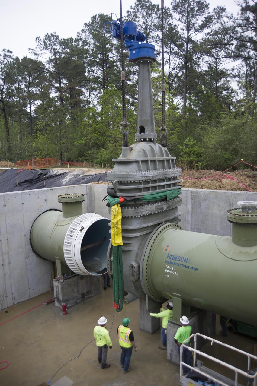
Stennis Space Center employees install a 96-inch valve during a recent upgrade of the high-pressure industrial water system that serves the site’s large rocket engine test stands. The upgraded system has a capacity to flow 335,000 gallons of water a minute, which is a critical element for testing. At Stennis, engines are anchored in place on large test stands and fired just as they are during an actual space flight. The fire and exhaust from the test is redirected out of the stand by a large flame trench. A water deluge system directs thousands of gallons of water needed to cool the exhaust. Water also must be available for fire suppression in the event of a mishap. The new system supports RS-25 engine testing on the A-1 Test Stand, as well as testing of the core stage of NASA’s new Space Launch System on the B-2 Test Stand at Stennis.
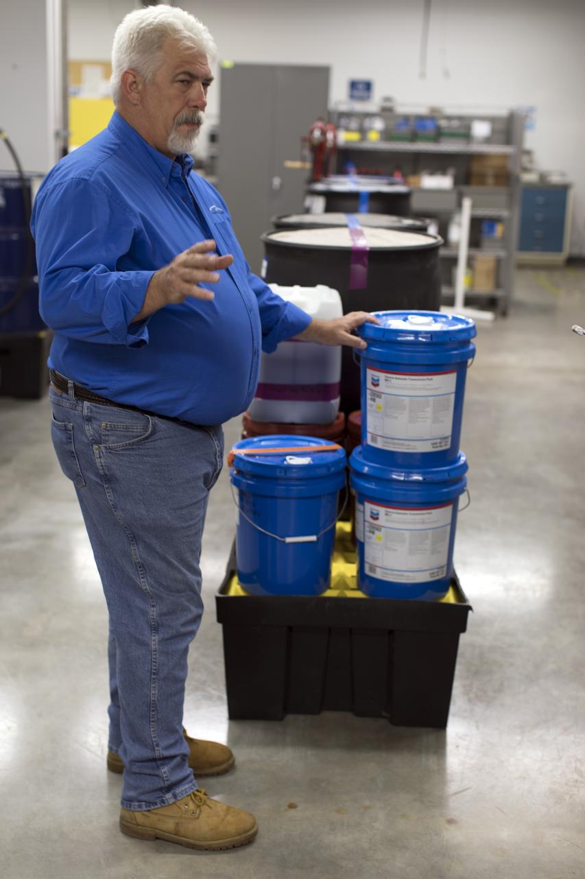
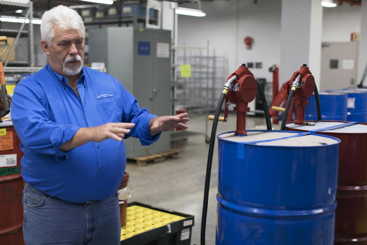
Tim King of Jacobs at NASA's Kennedy Space Center in Florida, explains operations in the Oil Pharmacy operated under the Test and Operations Support Contract, or TOSC. The facility consolidated storage and distribution of petroleum products used in equipment maintained under the contract. This included standardized naming, testing processes and provided a central location for distribution of oils used in everything from simple machinery to the crawler-transporter and cranes in the Vehicle Assembly Building.
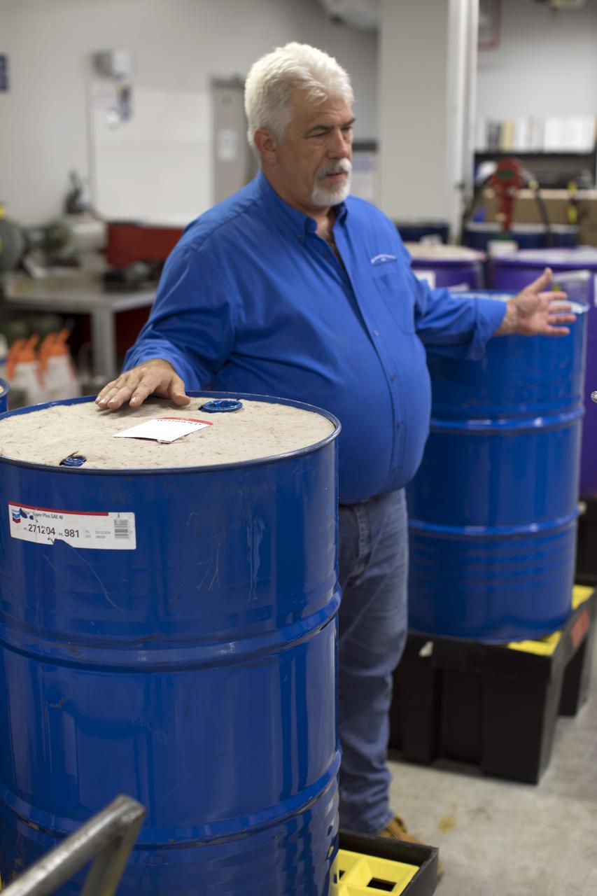
Tim King of Jacobs at NASA's Kennedy Space Center in Florida, explains operations in the Oil Pharmacy operated under the Test and Operations Support Contract, or TOSC. The facility consolidated storage and distribution of petroleum products used in equipment maintained under the contract. This included standardized naming, testing processes and provided a central location for distribution of oils used in everything from simple machinery to the crawler-transporter and cranes in the Vehicle Assembly Building.
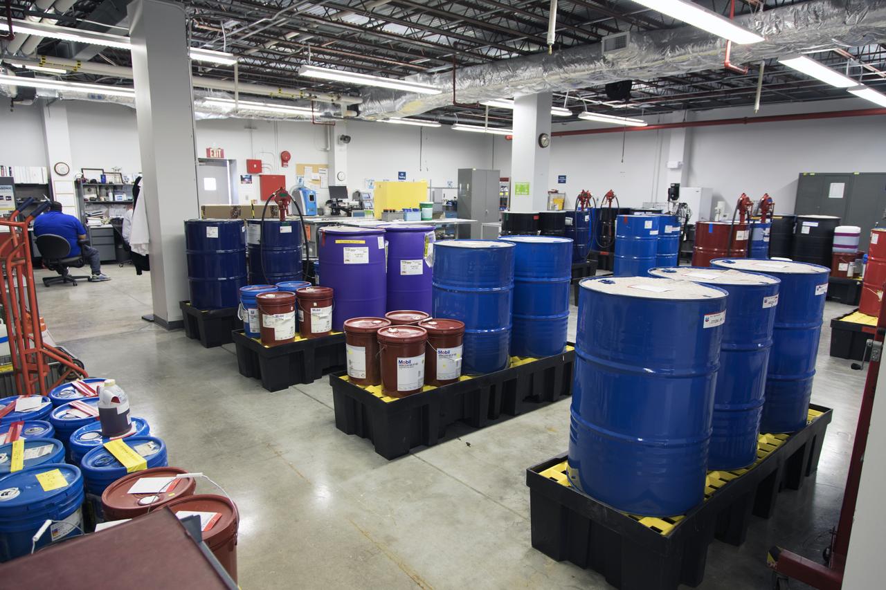
An overall view of the Oil Pharmacy operated under the Test and Operations Support Contract, or TOSC. The facility consolidated storage and distribution of petroleum products used in equipment maintained under the contract. This included standardized naming, testing processes and provided a central location for distribution of oils used in everything from simple machinery to the crawler-transporter and cranes in the Vehicle Assembly Building.
Tim King of Jacobs at NASA's Kennedy Space Center in Florida, explains operations in the Oil Pharmacy operated under the Test and Operations Support Contract, or TOSC. The facility consolidated storage and distribution of petroleum products used in equipment maintained under the contract. This included standardized naming, testing processes and provided a central location for distribution of oils used in everything from simple machinery to the crawler-transporter and cranes in the Vehicle Assembly Building.
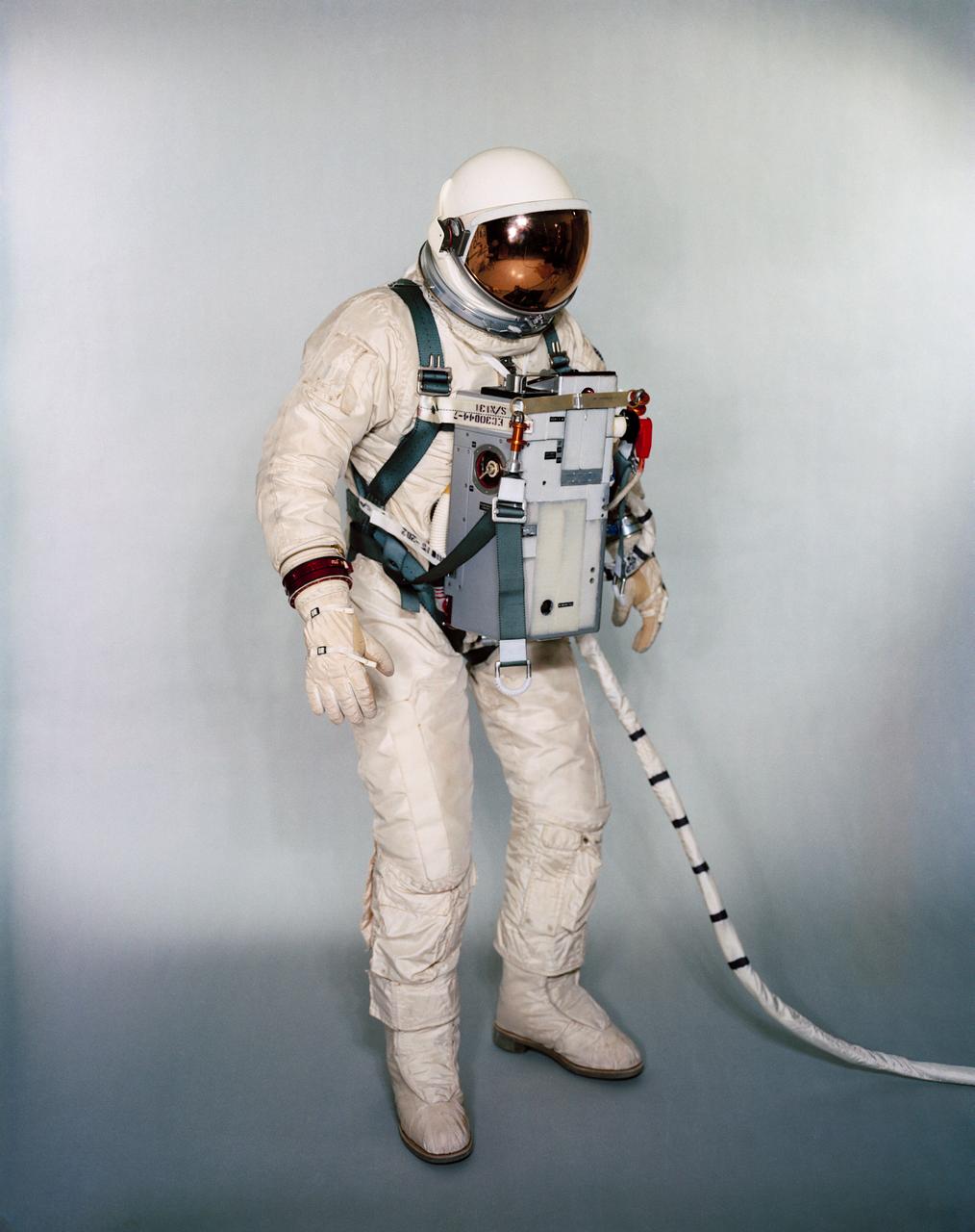
S67-24267 (1966) --- Suited test subject equipped with Gemini-12 Life Support System and waist tethers for extravehicular activity (EVA). Photo credit: NASA
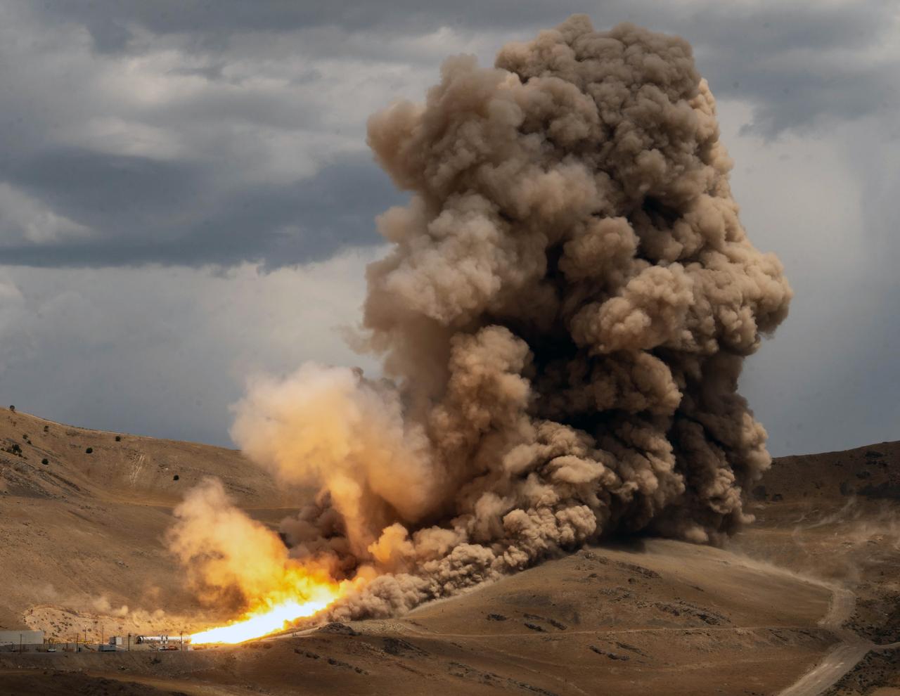
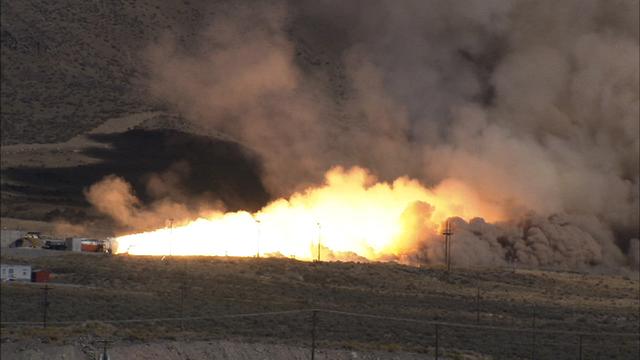
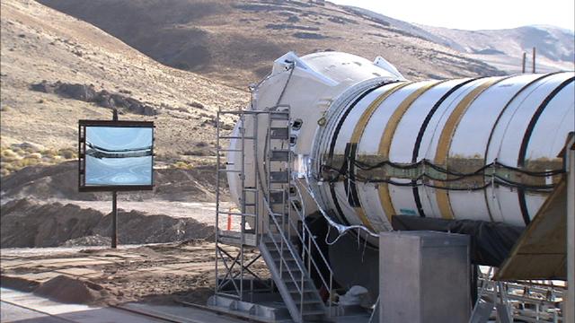
NASA and Northrop Grumman completed a solid rocket booster motor ground test for future flights of the agency’s Space Launch System rocket at Northrop Grumman’s test facility in Promontory, Utah, July 21. The booster motor, called Flight Support Booster-2 (FSB-2), fired for a little over two minutes and produced more than 3.6 million pounds of thrust. Test data will be used to evaluate improvements and new materials in the boosters for missions after Artemis III. When SLS launches the Artemis missions to the Moon, its two five-segment solid rocket boosters produce more than 75% of the initial thrust. The SLS boosters are the largest, most powerful boosters ever built for flight. For more information about SLS, visit nasa.gov/sls
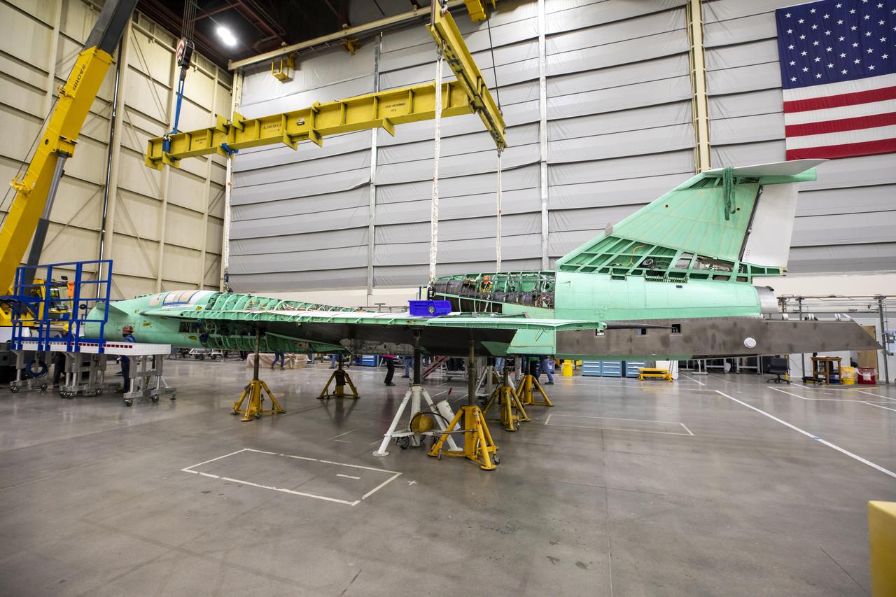
A view of the X-59 being supported by ground supports in preparation for installation of the landing gear and other hardware required for structural testing. Lockheed Martin Photography By Garry Tice 1011 Lockheed Way, Palmdale, Ca. 93599 Event: Removal From Tooling Jig Date: 10/27/2021 Additional Info:
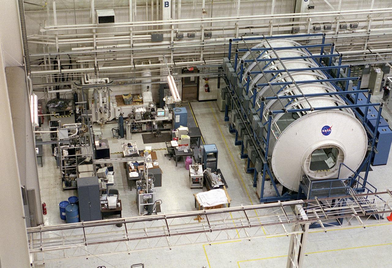
The Marshall Space Flight Center (MSFC) is responsible for designing and building the life support systems that will provide the crew of the International Space Station (ISS) a comfortable environment in which to live and work. Scientists and engineers at the MSFC are working together to provide the ISS with systems that are safe, efficient, and cost-effective. These compact and powerful systems are collectively called the Environmental Control and Life Support Systems, or simply, ECLSS. In this photograph, the life test area on the left of the MSFC ECLSS test facility is where various subsystems and components are tested to determine how long they can operate without failing and to identify components needing improvement. Equipment tested here includes the Carbon Dioxide Removal Assembly (CDRA), the Urine Processing Assembly (UPA), the mass spectrometer filament assemblies and sample pumps for the Major Constituent Analyzer (MCA). The Internal Thermal Control System (ITCS) simulator facility (in the module in the right) duplicates the function and operation of the ITCS in the ISS U.S. Laboratory Module, Destiny. This facility provides support for Destiny, including troubleshooting problems related to the ITCS.
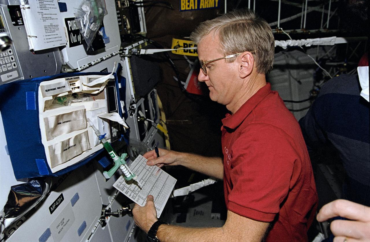
STS062-10-010 (4-18 March 1994) --- Astronaut John H. Casper, mission commander, takes stock of paraphenalia used to support medical testing onboard Columbia's middeck. Casper was poind by four other veteran astronauts for 14 days of variegated research in earth orbit.
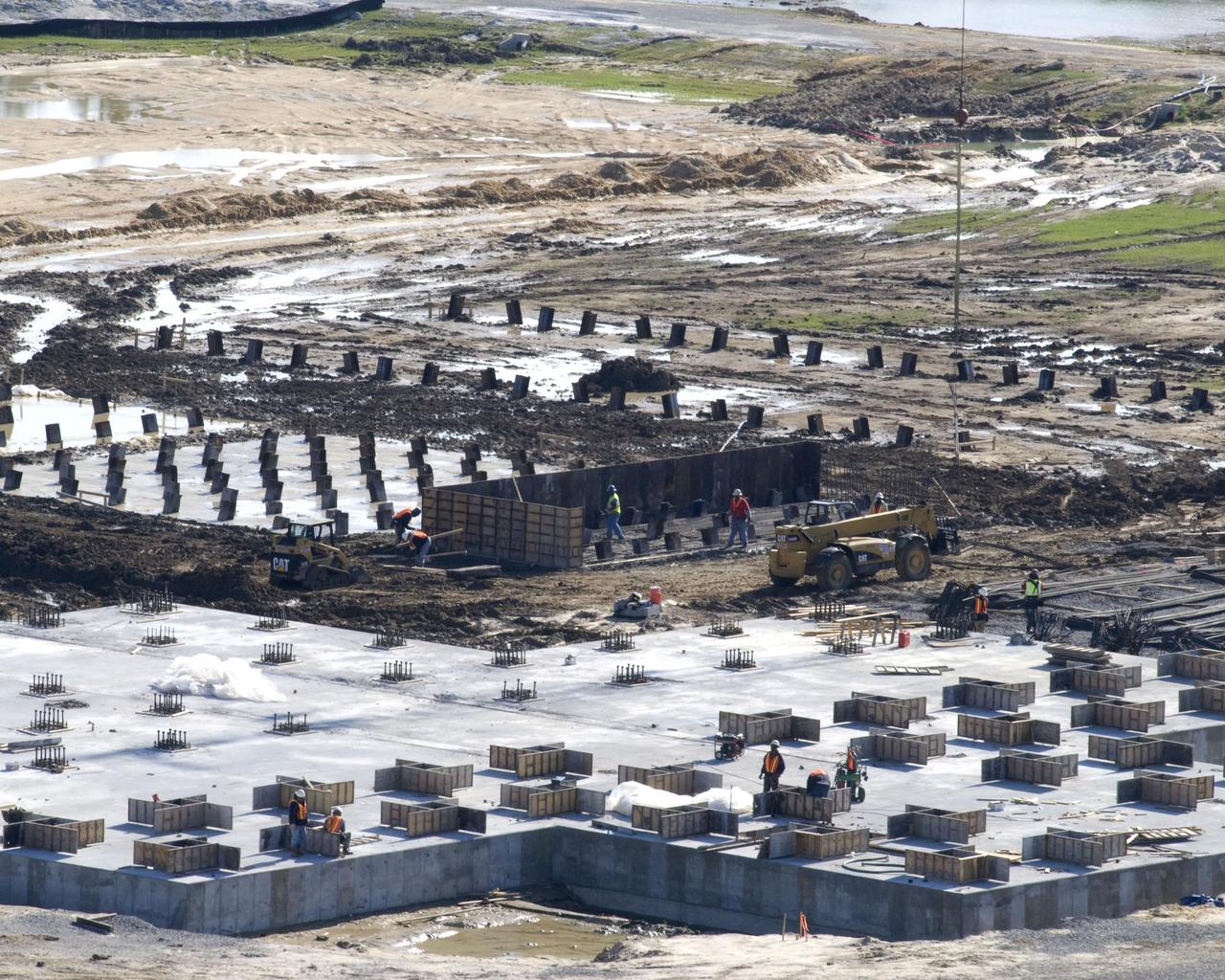
The concrete foundation placed Dec. 18 (foreground) for Stennis Space Center's future A-3 Test Stand has almost completely cured by early January, according to Bo Clarke, NASA's contracting officer technical representative for the foundation contract. By late December, construction on foundations for many of the test stand's support structures - diffuser, liquid oxygen, isopropyl alcohol and water tanks and gaseous nitrogen bottle battery - had begun with the installation of (background) `mud slabs.' The slabs provide a working surface for the reinforcing steel and foundation forms.
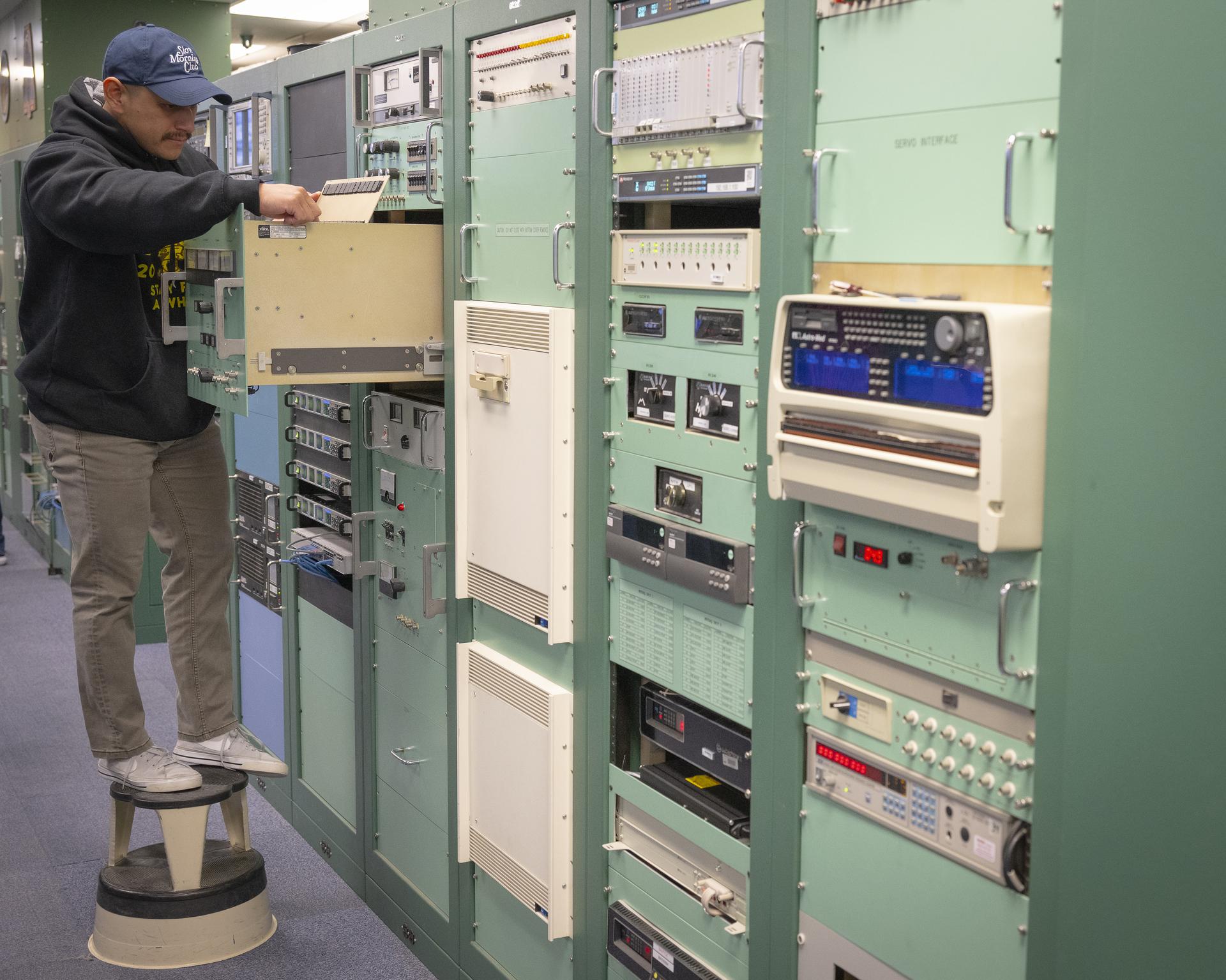
Mission technician Phillips Boche checks on components that support radar tracking at NASA’s Armstrong Flight Research Center in Edwards, California, on Sept. 30, 2025. Boche is part of the center’s Dryden Aeronautical Test Range, which provides voice and tracking support to the International Space Station.
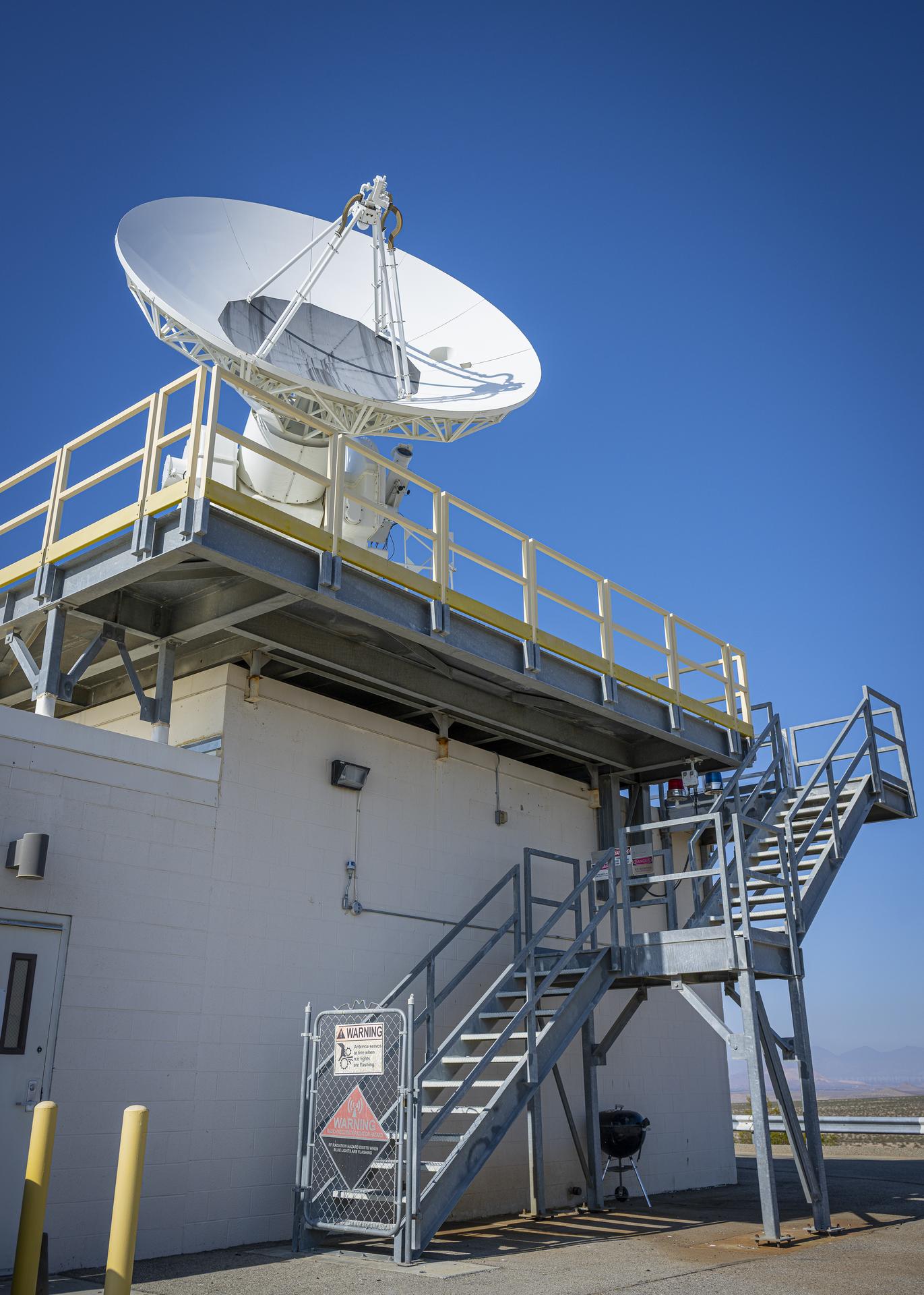
This is one of two radars that support radar tracking of the International Space Station at NASA’s Armstrong Flight Research Center in Edwards, California, on Sept. 30, 2025. Radar tracking is one of the key capabilities of the center’s Dryden Aeronautical Test Range, which provides voice and tracking support to the International Space Station.
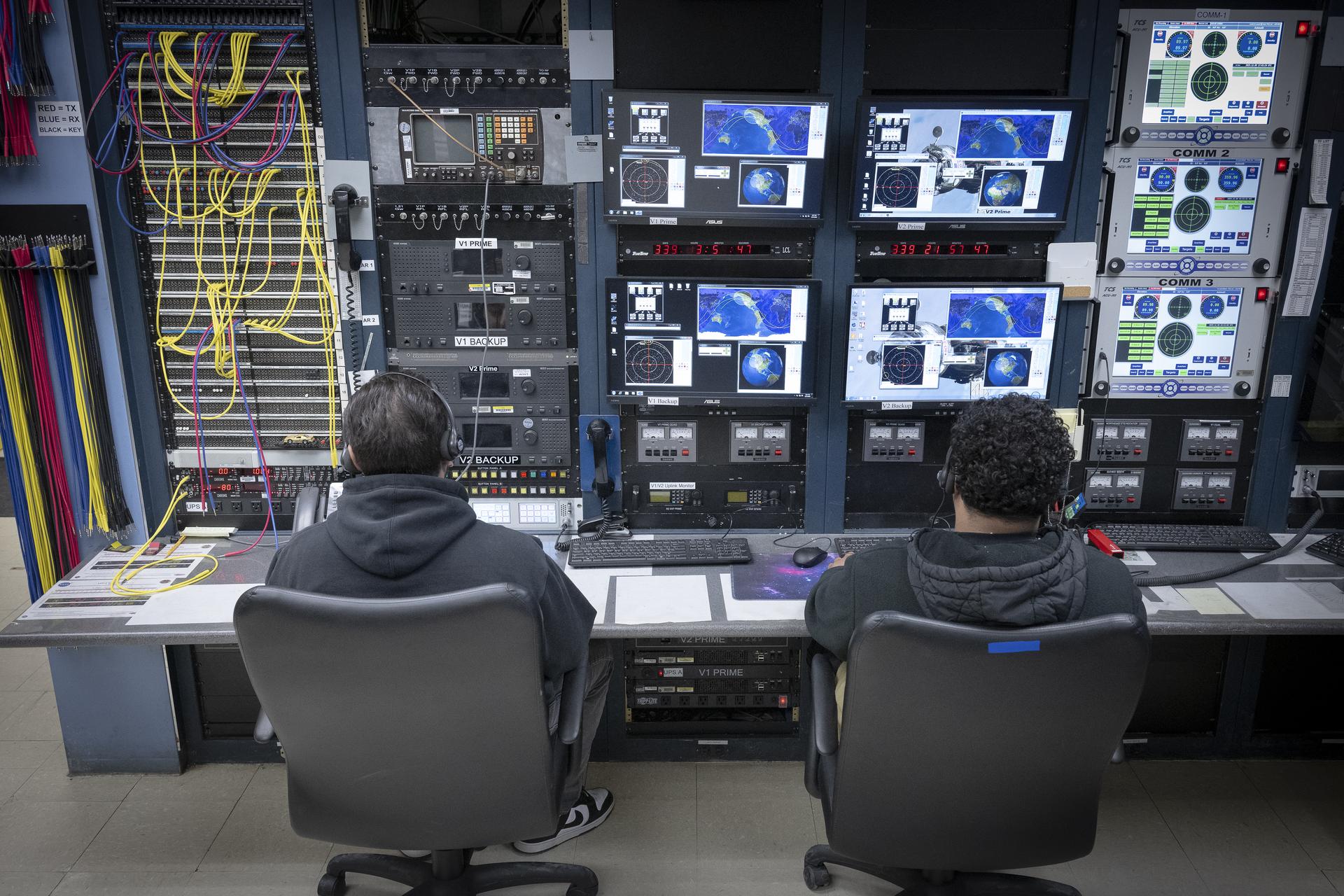
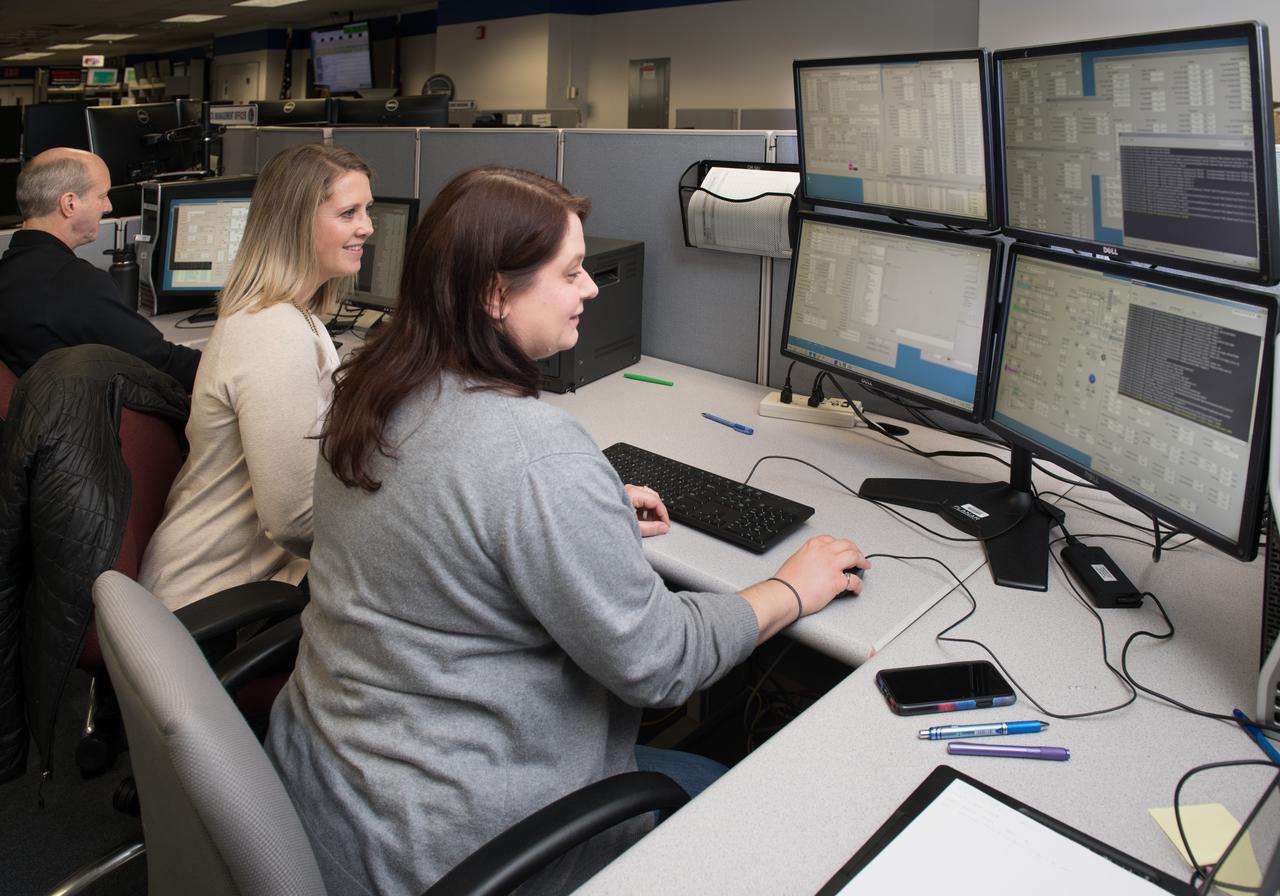
Range operators at the Dryden Aeronautical Test Range at NASA’s Armstong Flight Research Center in Edwards, California, provide voice and tracking support to the International Space Station. In this Friday, Dec. 6, 2025, photo, Alex Oganesyan, left, and Deming Ingles are shown at their workstations, where they support communications backup for space station missions.
Range operators at the Dryden Aeronautical Test Range at NASA’s Armstong Flight Research Center in Edwards, California, provide voice and tracking support to the International Space Station. In this Friday, Dec. 6, 2025, photo, Alex Oganesyan, left, and Deming Ingles are shown at their workstations, where they support communications backup for space station missions.
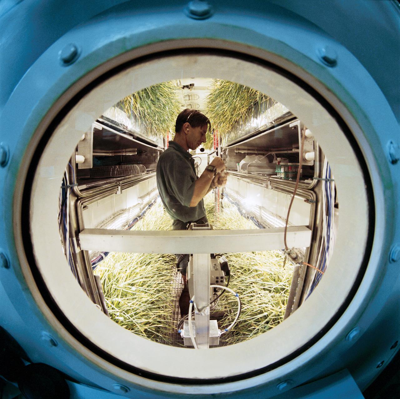
Early Human Testing (EHT) Initiative Phase 1 Regenerative Life Support Systems Laboratory (RLSSL). Nigel Packham activities in the Variable Pressure Growth Chamber which he lived inside for 15 days. A crowd of well-wishers outside the test chamber, at the console are John Lewis, Ed Mohr and Marybeth Edeen (15577). Packham exiting the chamber (15578-81). Packham is the focus of television cameras and reporters (15582-3). Don Henninger interviewed by reporters (15584). Packham is presented with a jacket after his stay in the chamber (15585). Packham inside the wheat growth chamber checking the condition of the plants (15586-7, 15597). Packham exercising on a recumbant bicycle (15588, 15592). Packham, through the window into the growth chamber, displays a handful of wheat plants to console monitor Dan Barta (15589-90). Group portrait of the team conducting the Early Human Testing Initiative Phase 1 Regenerative Life Support Systems test and include, front row, from left: Jeff Dominick and Don Overton and back row, from left, unidentified member, Marybeth Edeen, Nigel Packham, John Lewis, Ed Mohr, Dan Barta and Tim Monk (15591). Harry Halford prepares to send a package through the airlock to Packham (15593). Packham displays a handful of wheat plants (15594). Packham fixes himself a bowl of cereal (15595) and retrieves a carton of milk from the refrigerator (15596). Packham retrieves a package from the airlock (15598). Packham packs up trash in plastic bag (15599-600) and sends it back through the airlock (15601). Packham gets a cup of water (15602) and heats it in the microwave (15603).
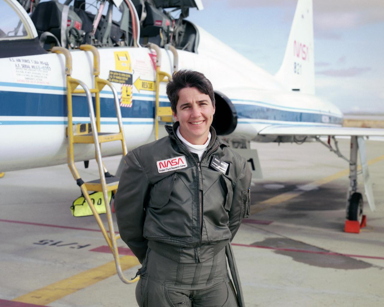
Marta Bohn-Meyer flew as a back-seat flight test engineer in this NASA T-38 mission support aircraft when this 1993 photo was taken.
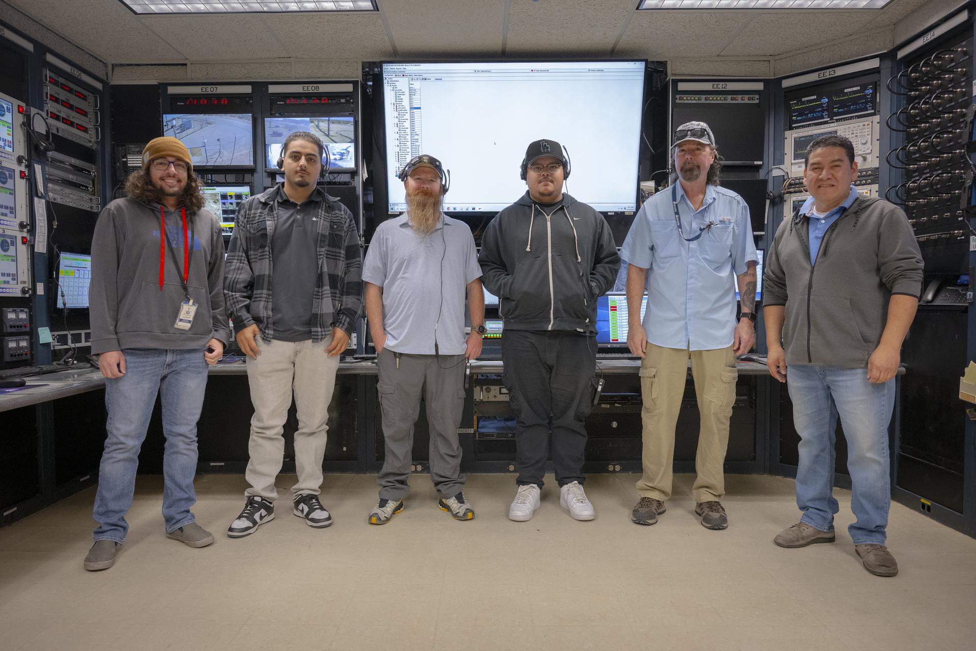
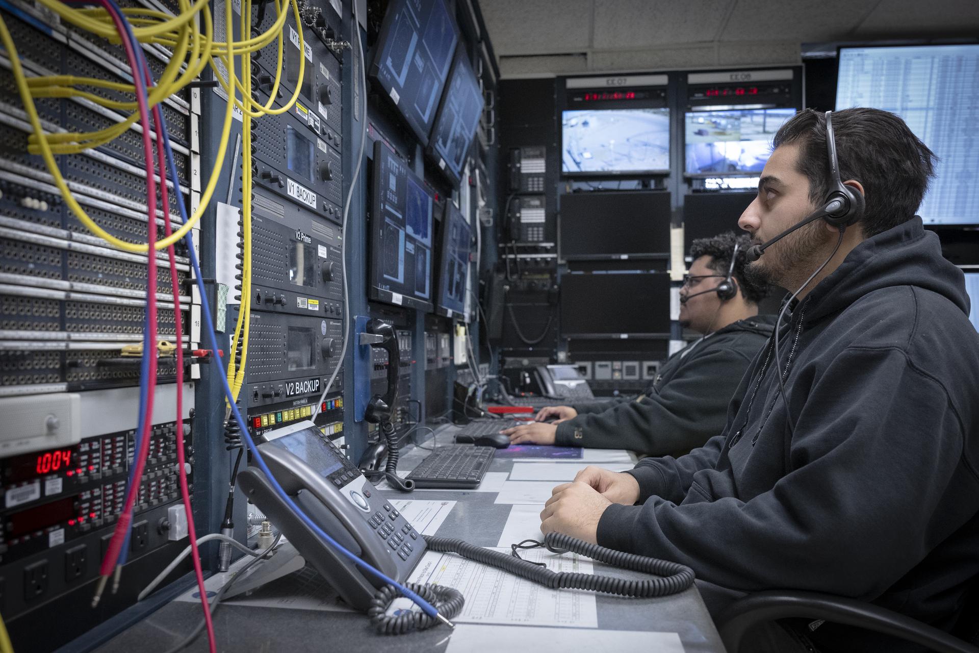
Mission technicians, from left, Adam Cataldo, Alex Oganesyan, Daniel Kelly, Deming Ingles, Mike Gibson, and Kelvin Menendez support communications backup for an International Space Station mission on Tuesday, Sept. 30, 2025, at NASA’s Armstong Flight Research Center in Edwards, California. The team is part of the center’s Dryden Aeronautical Test Range, which provides voice and tracking support to the space station.
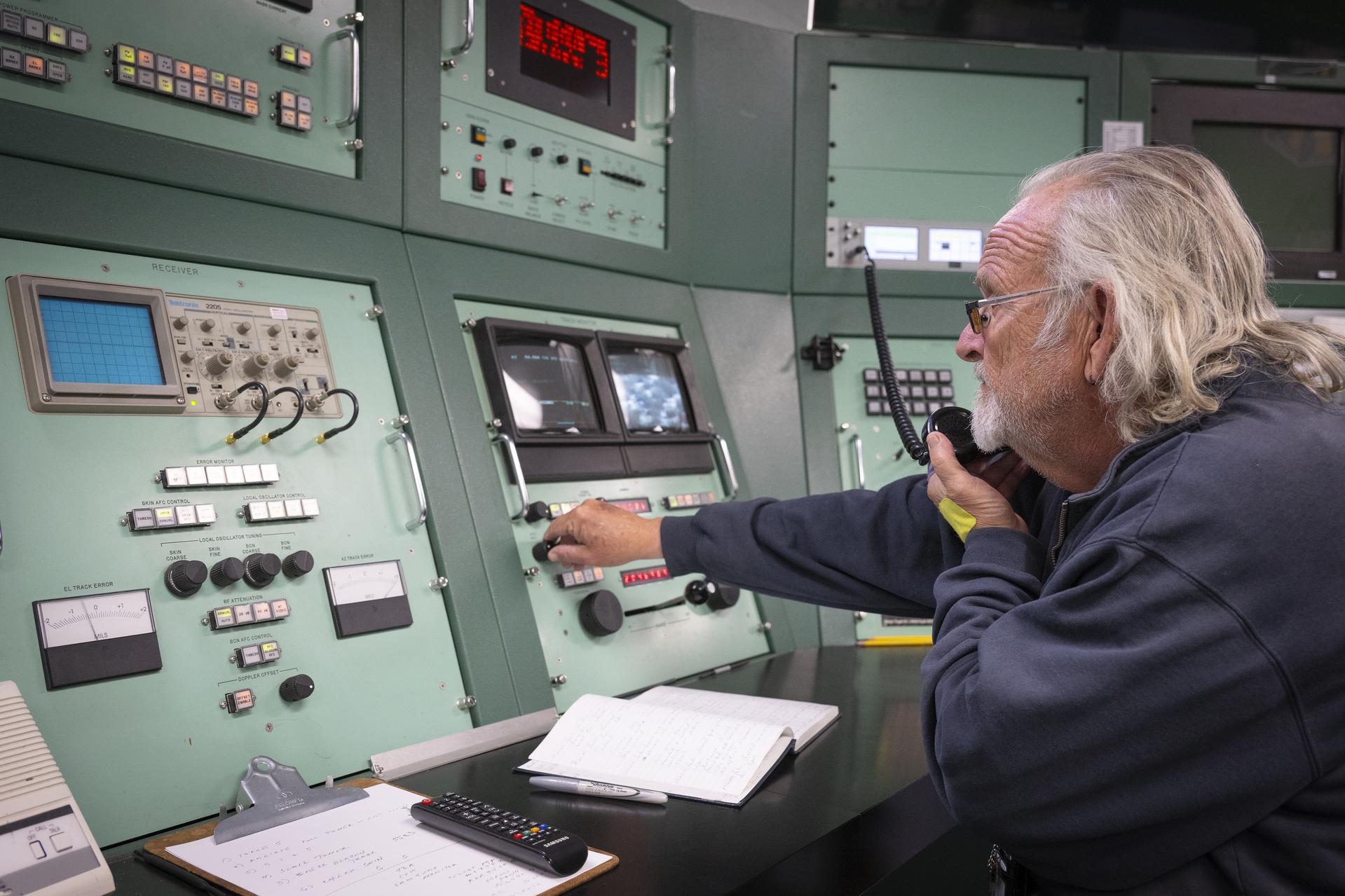
Mission operator Mike Webb sits at one of the radar stations used to track the International Space Station as it passes high above NASA’s Armstrong Flight Research Center in Edwards, California, on Sept. 30, 2025. Webb is part of the center’s Dryden Aeronautical Test Range, which provides voice and tracking support to the space station.
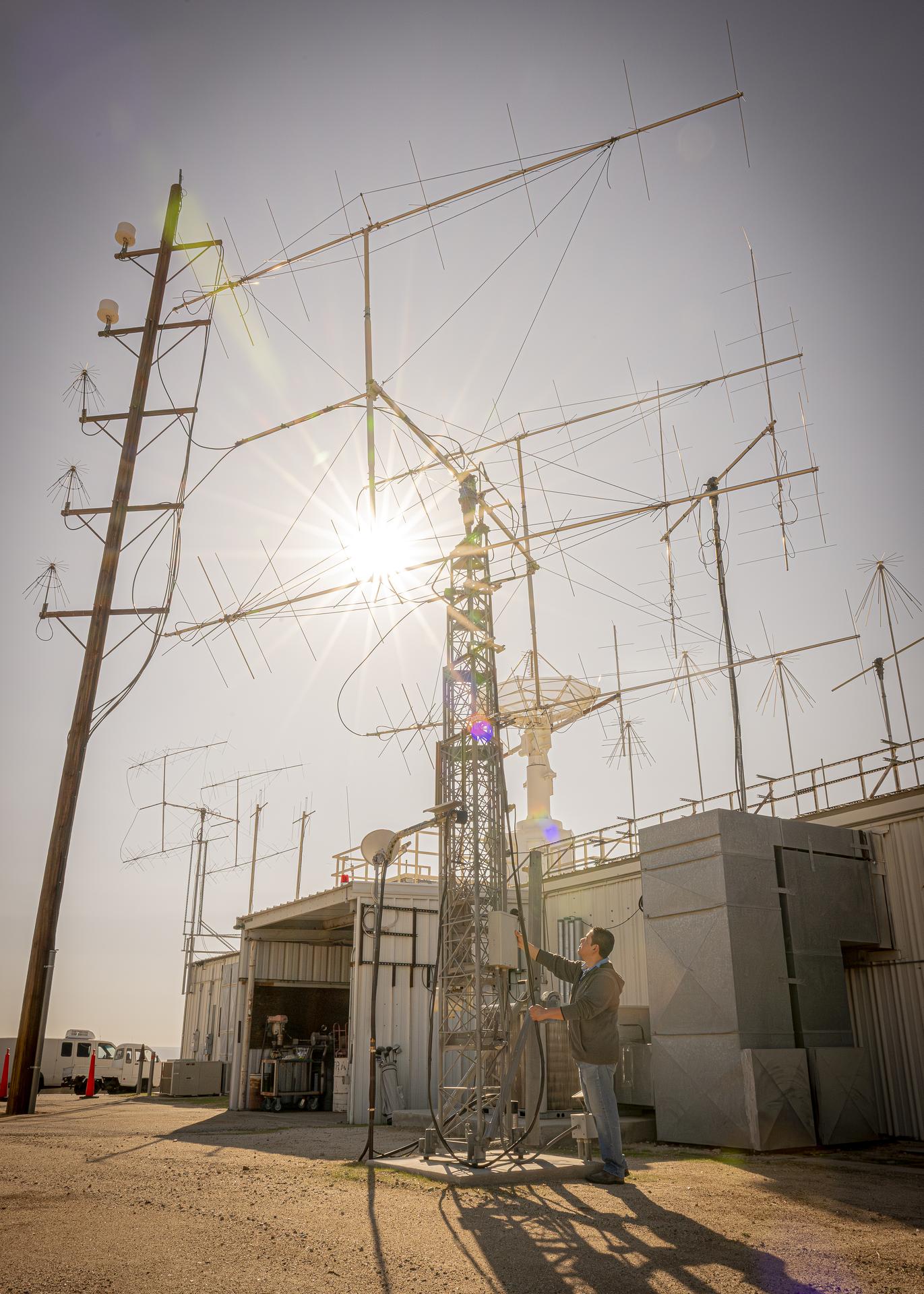
Mission operator Kelvin Menendez watches as antennas rise to track the International Space Station as it passes high above NASA’s Armstrong Flight Research Center in Edwards, California, on Sept. 30, 2025. Menendez is part of the center’s Dryden Aeronautical Test Range, which provides voice and tracking support to the space station.
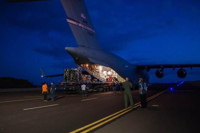
Engineers unload ground support equipment for a June engineering test flight above Kauai, Hawaii. The test flight is part of NASA LDSD project, which is investigating cutting-edge landing technologies that could fly on future Mars missions.
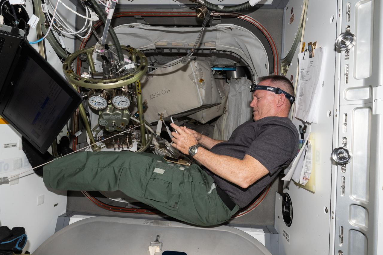
iss071e318564 (July 10, 2024) --- NASA astronaut and Boeing's Crew Flight Test Commander Butch Wilmore reviews procedures on a computer tablet for life support maintenance work aboard the International Space Station.
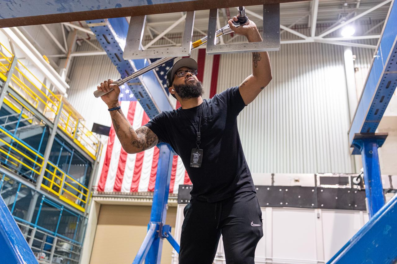
Mechanical engineering and integration technician Ivan Pratt installs brackets onto the static load testing platform in preparation of an OSAM-1 ground support equipment proof test at Goddard Space Flight Center, Greenbelt Md., July 19, 2023. This photo has been reviewed by OSAM1 project management and the Export Control Office and is released for public view. NASA/Mike Guinto
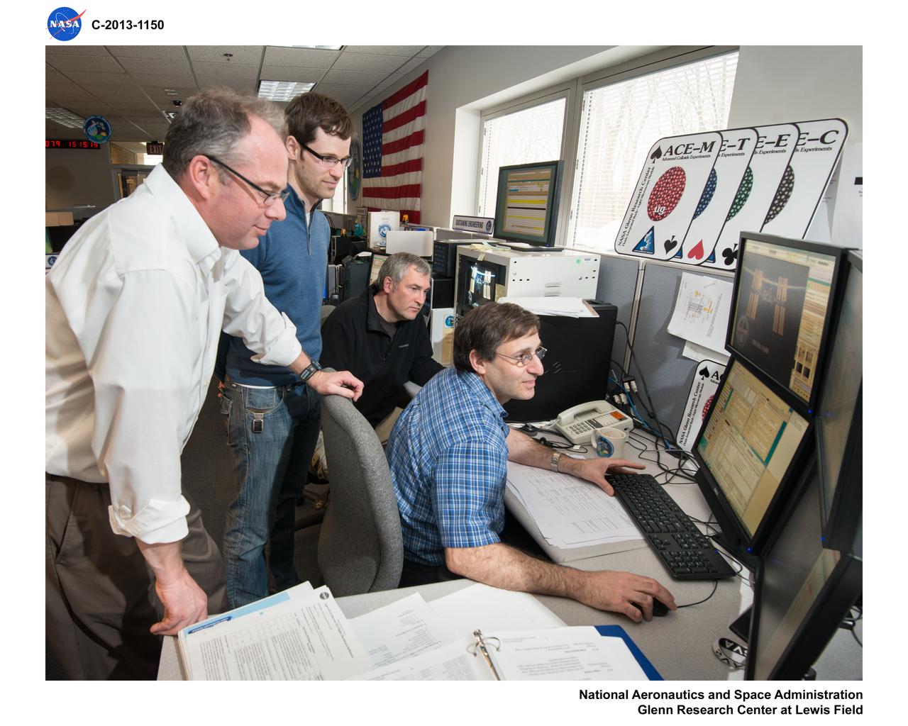
Testing of software with ground hardware for the Structue and Response of Spherical Diffusion Flames, s-Flame, experiment - of the Advanced Combustion via Microgravity Experiments, ACME, project conducted in the ISS Combustion Integrated Rack, CIR - by ACME Software Engineer Jeffrey Eggers, Operations Lead Angela Adams, and Planning Lead Melani Smajdek in the Telescience Support Center, TSC, also known as the Glenn ISS Payload Operations Center, GIPOC
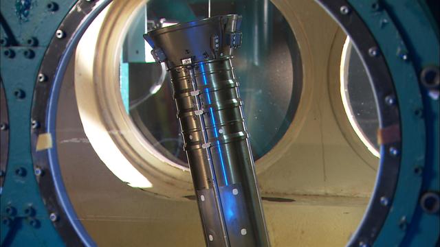
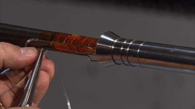
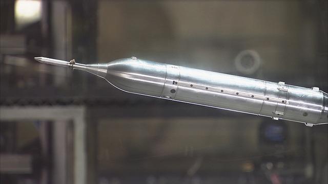
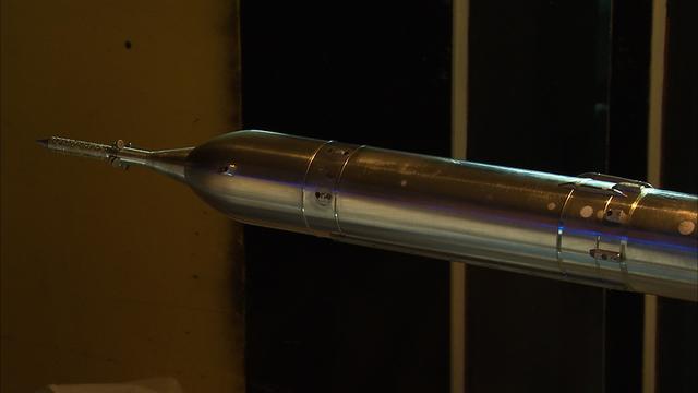
THIS IS A TEST OF THE 1ST STAGE RE-ENTRY VEHICLE. HEAT TESTING OF A 3% MODEL TO SUPPORT THE ARES/ CLV FIRST STAGE RE-ENTRY. THIS TEST OCCURRED AT ARNOLD AIR FORCE BASE, TENNESSEE. THIS TESTING SUPPORTS THE DEVELOPMENT OF THE CONSTELLATION/ARES PROJECT. THIS IMAGE IS EXTRACTED FROM A HIGH DEFINITION VIDEO FILE AND IS THE HIGHEST RESOLUTION AVAILABLE.
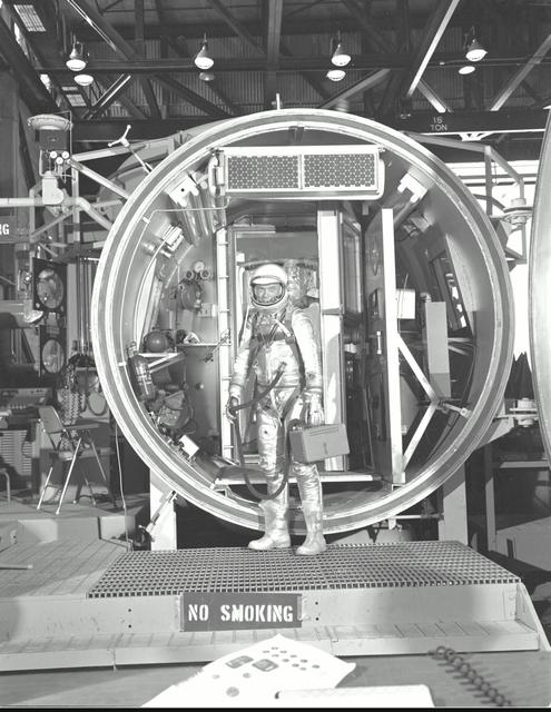
M61-00150 (1961) --- Astronaut John H. Glenn Jr., suited with hose to suit ventilation unit attached, during altitude chamber test. He is standing in the entrance to the test chamber with his helmet visor down. Photo credit: NASA
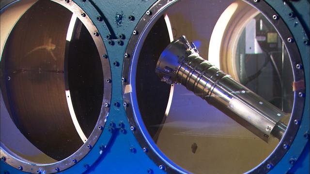
THIS IS A MODEL TEST OF THE 1ST STAGE RE-ENTRY. HEAT TESTING OF A 3% MODEL TO SUPPORT THE ARES/CLV FIRST STAGE RE-ENTRY. THIS OCCURRED AT ARNOLD AIR FORCE BASE, TENNESSEE IN SUPPORT OF THE CONSTELLATION/ARES PROJECT. THIS IMAGE IS EXTRACTED FROM A HIGH DEFINITION VIDEO FILE AND IS THE HIGHEST RESOLUTION AVAILABLE.
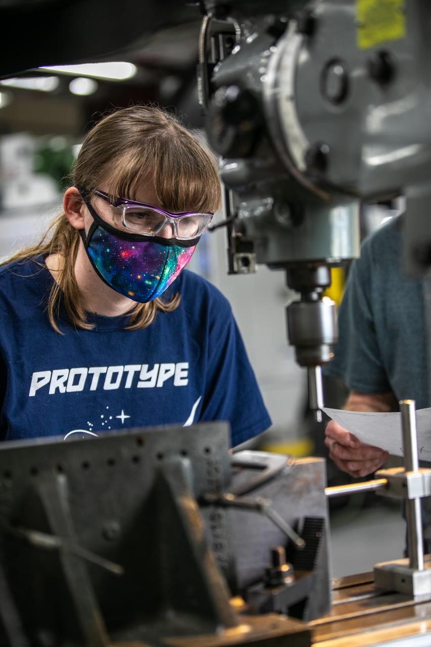
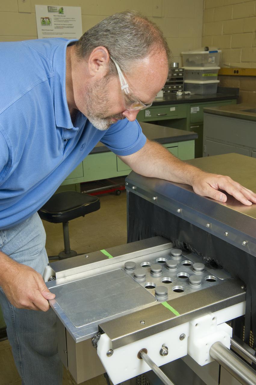
Katie Mortensen, a mechanical engineering technician, machines test article materials inside the Prototype Development Laboratory at NASA’s Kennedy Space Center in Florida on Oct. 21, 2020. The prototype laboratory designs, fabricates, and tests prototypes, test articles and test support equipment. It has a long history of providing fast solutions to complex operations problems. The lab’s teams of engineers use specialized equipment to produce exacting, one-of-a-kind items made from a range of materials depending on the design. The lab supports projects at Kennedy and at the agency level.
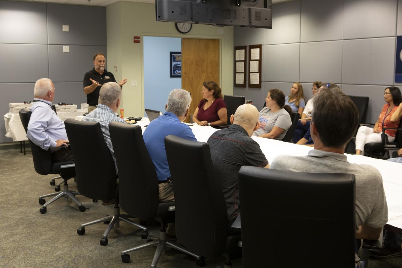
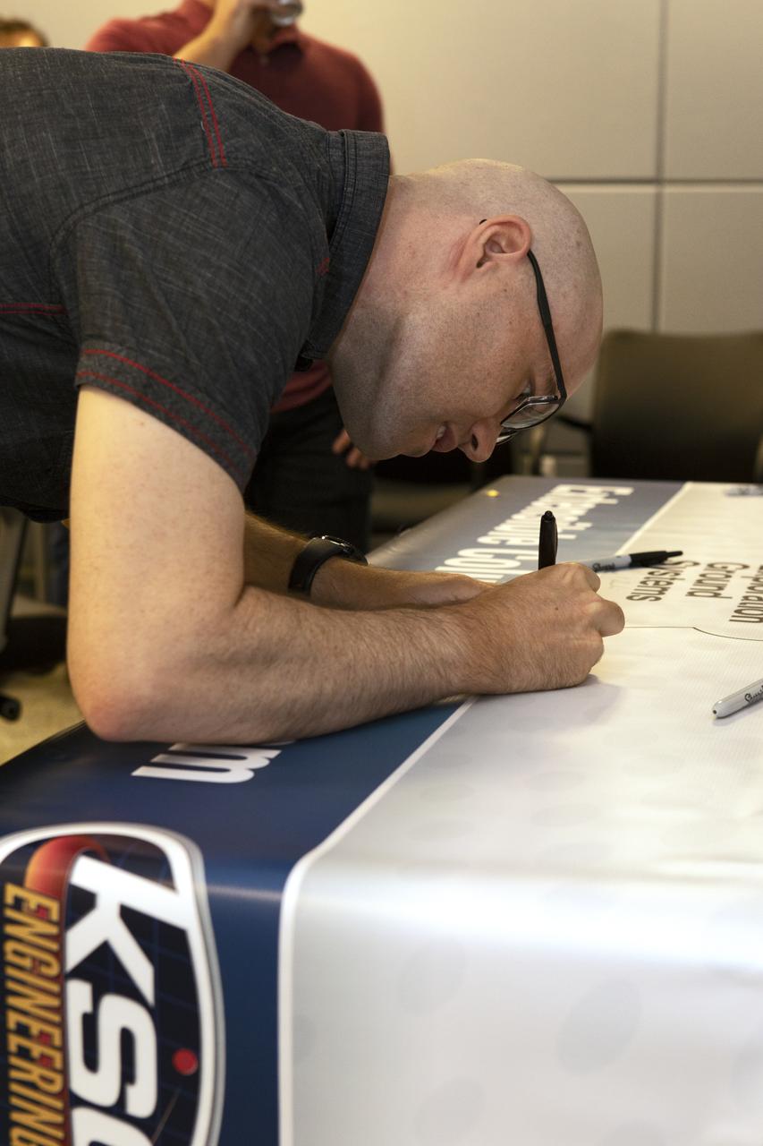
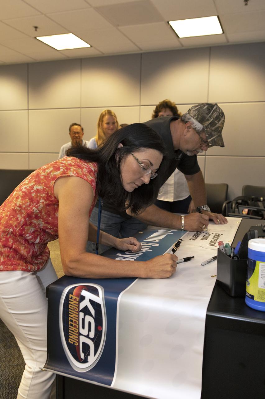
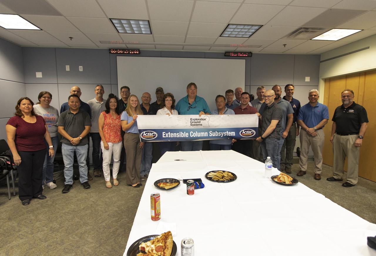
Engineers celebrate the completion of the Extensible Column Subsystem (XCS) project during a banner event held in Operations Support Building II at Kennedy Space Center. The XCS team successfully executed an aggressive schedule, receiving outstanding support from the fabrication contractor, Met-Con. Full functional testing occurred at Met-Con’s facility, with no mechanical or structural issues. All four columns and the test fixture have been delivered to Kennedy. Full-scale testing will take place when the Mobile Launcher gets to the pad later this summer.

Engineers celebrate the completion of the Extensible Column Subsystem (XCS) project during a banner event held in Operations Support Building II at Kennedy Space Center. The XCS team successfully executed an aggressive schedule, receiving outstanding support from the fabrication contractor, Met-Con. Full functional testing occurred at Met-Con’s facility, with no mechanical or structural issues. All four columns and the test fixture have been delivered to Kennedy. Full-scale testing will take place when the Mobile Launcher gets to the pad later this summer.
Engineers celebrate the completion of the Extensible Column Subsystem (XCS) project during a banner event held in Operations Support Building II at Kennedy Space Center. The XCS team successfully executed an aggressive schedule, receiving outstanding support from the fabrication contractor, Met-Con. Full functional testing occurred at Met-Con’s facility, with no mechanical or structural issues. All four columns and the test fixture have been delivered to Kennedy. Full-scale testing will take place when the Mobile Launcher gets to the pad later this summer.
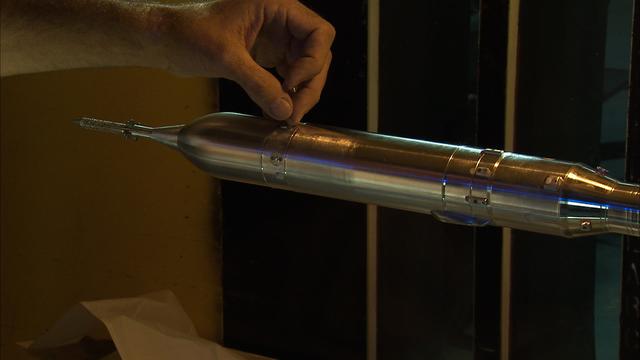
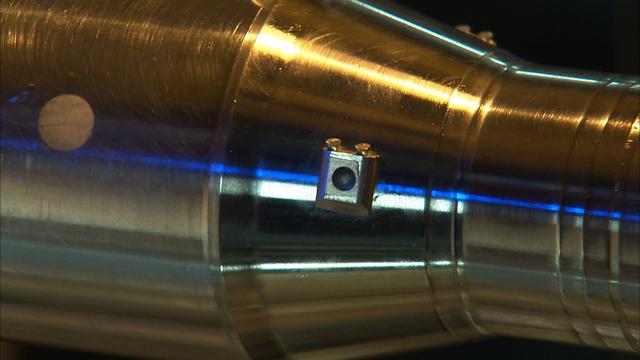
Active damper wind tunnel test in support of the development of Constellation/Ares. Testing of the 1% and .548% models for active damper and wall interference assessment in support of the Ares/CLV integrated vehicle. This test occurred at the 11 foot wind tunnel at the Ames Research Center, California. This image is extracted from high definition video file and is the highest resolution available.

Engineers celebrate the completion of the Extensible Column Subsystem (XCS) project during a banner event held in Operations Support Building II at Kennedy Space Center. The XCS team successfully executed an aggressive schedule, receiving outstanding support from the fabrication contractor, Met-Con. Full functional testing occurred at Met-Con’s facility, with no mechanical or structural issues. All four columns and the test fixture have been delivered to Kennedy. Full-scale testing will take place when the Mobile Launcher gets to the pad later this summer.
Active damper wind tunnel test in support of the development of Constellation/Ares. Testing of the 1% and .548% models for active damper and wall interference assessment in support of the Ares/CLV integrated vehicle. This test occurred at the 11 foot wind tunnel at the Ames Research Center, California. This image is extracted from high definition video file and is the highest resolution available
Engineers celebrate the completion of the Extensible Column Subsystem (XCS) project during a banner event held in Operations Support Building II at Kennedy Space Center. The XCS team successfully executed an aggressive schedule, receiving outstanding support from the fabrication contractor, Met-Con. Full functional testing occurred at Met-Con’s facility, with no mechanical or structural issues. All four columns and the test fixture have been delivered to Kennedy. Full-scale testing will take place when the Mobile Launcher gets to the pad later this summer.
Active damper wind tunnel test in support of the development of Constellation/Ares. Testing of the 1% and .548% models for active damper and wall interference assessment in support of the Ares/CLV integrated vehicle. This test occurred at the 11 foot wind tunnel at the Ames Research Center, California. This image is extracted from high definition video file and is the highest resolution available.
Engineers celebrate the completion of the Extensible Column Subsystem (XCS) project during a banner event held in Operations Support Building II at Kennedy Space Center. The XCS team successfully executed an aggressive schedule, receiving outstanding support from the fabrication contractor, Met-Con. Full functional testing occurred at Met-Con’s facility, with no mechanical or structural issues. All four columns and the test fixture have been delivered to Kennedy. Full-scale testing will take place when the Mobile Launcher gets to the pad later this summer.
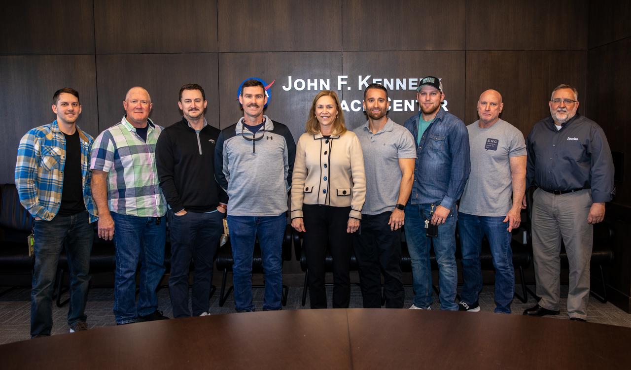
Kennedy Space Center Janet Petro recognizes the Red Crew/High Crew for their support of the Artemis I test flight.
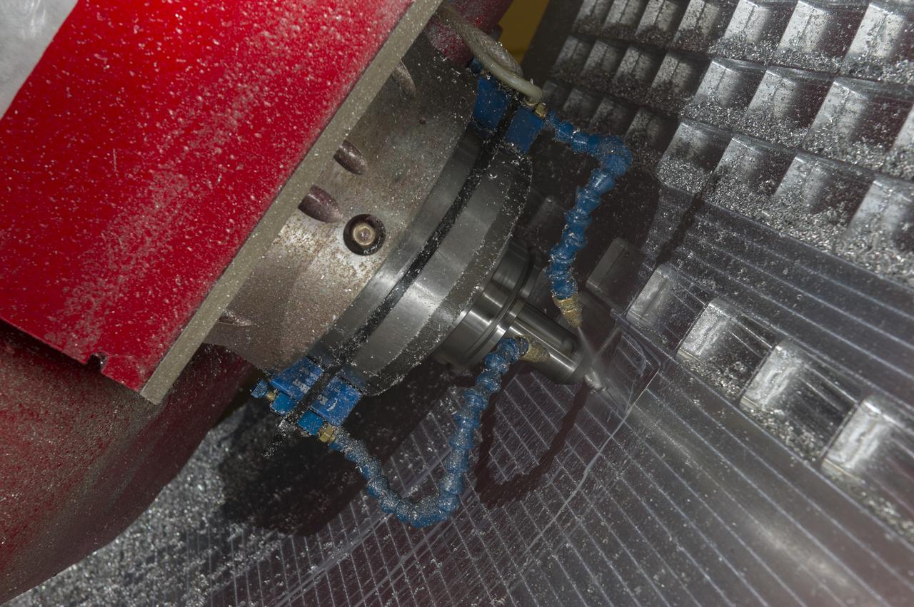
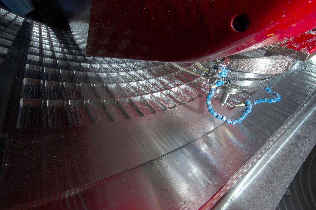
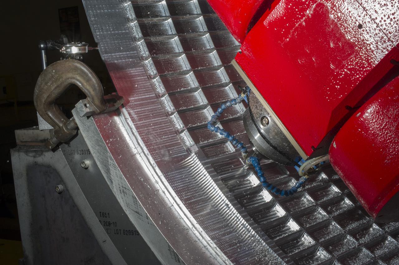
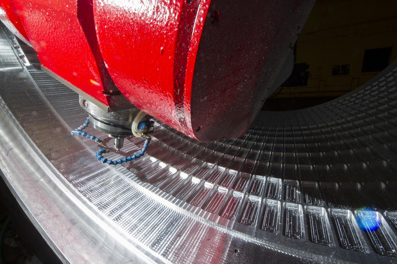
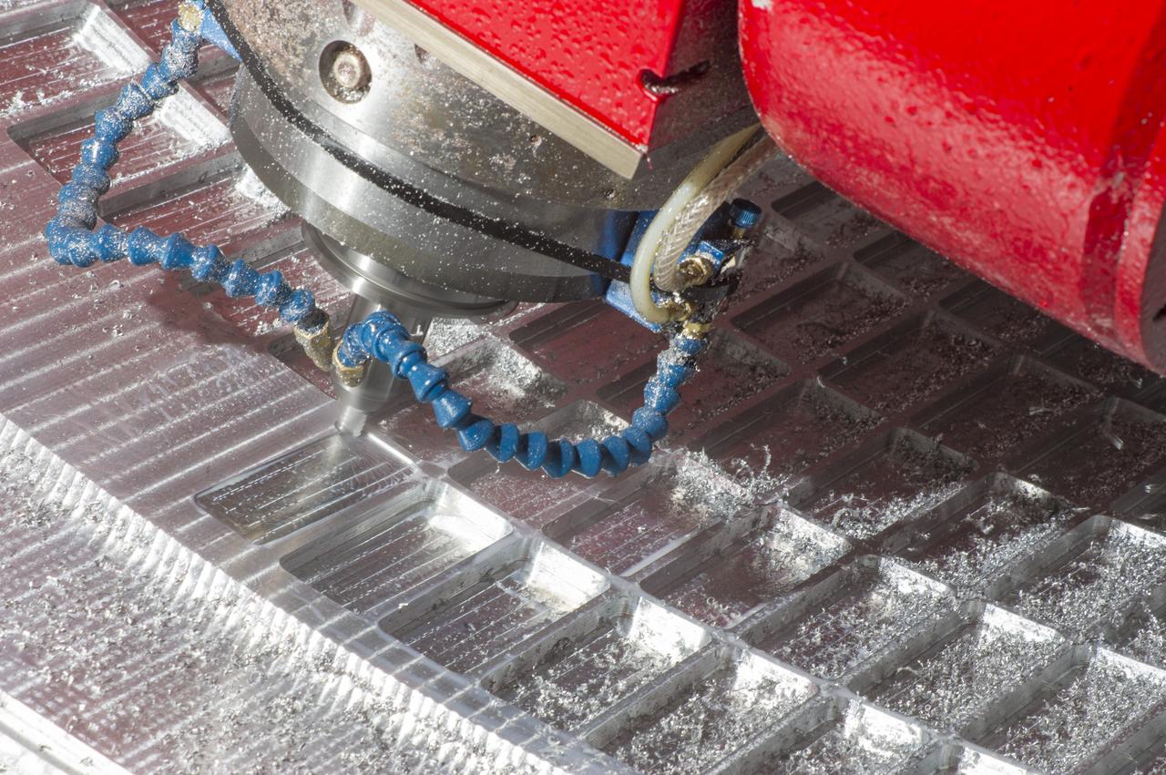
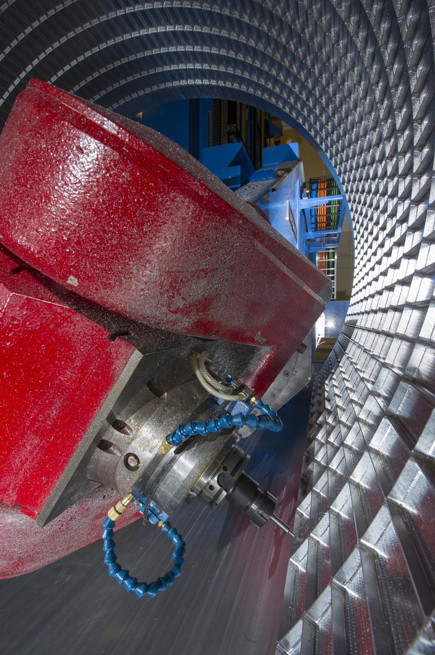
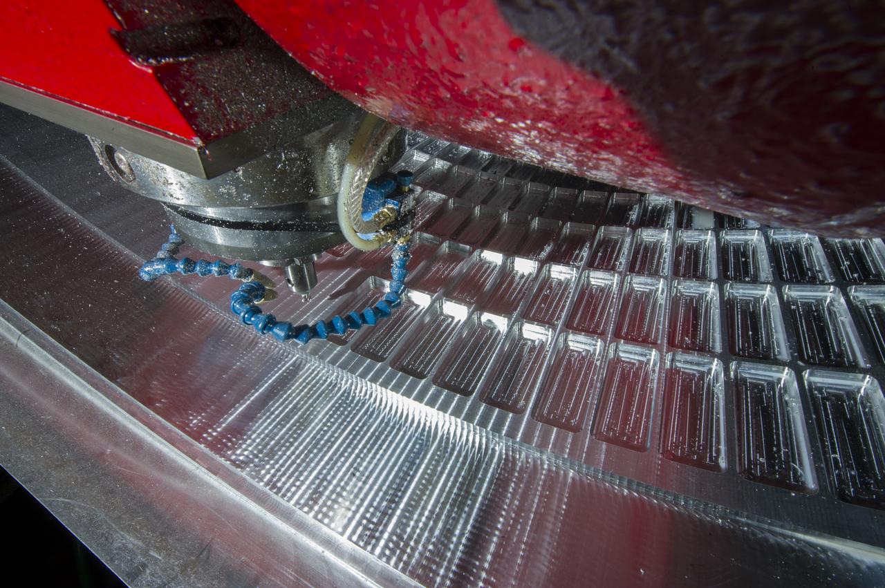
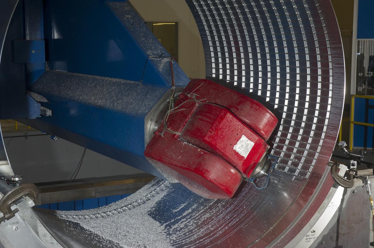
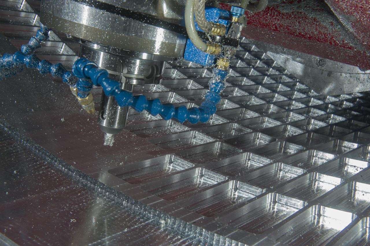
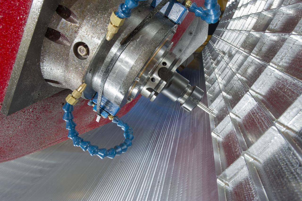
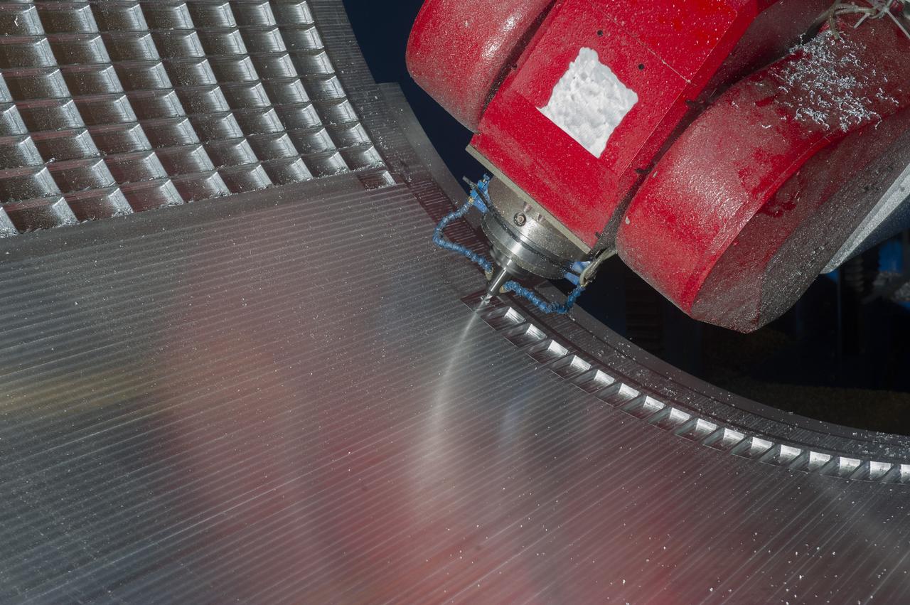
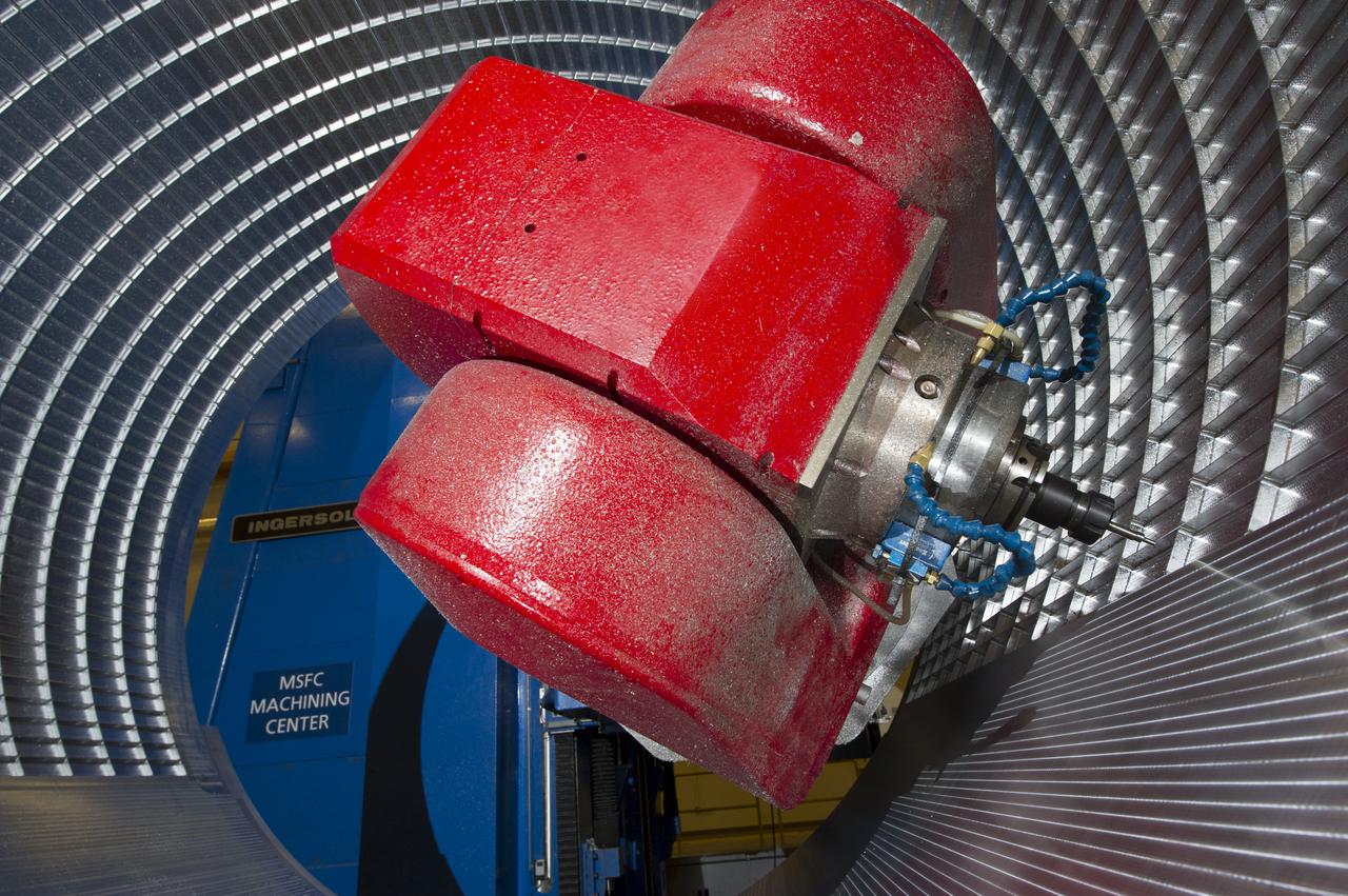
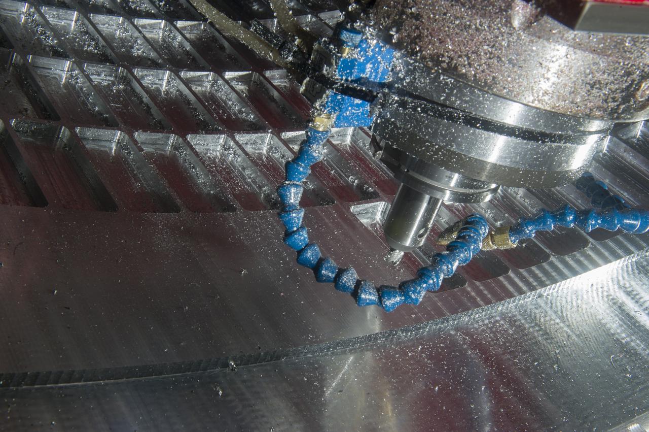
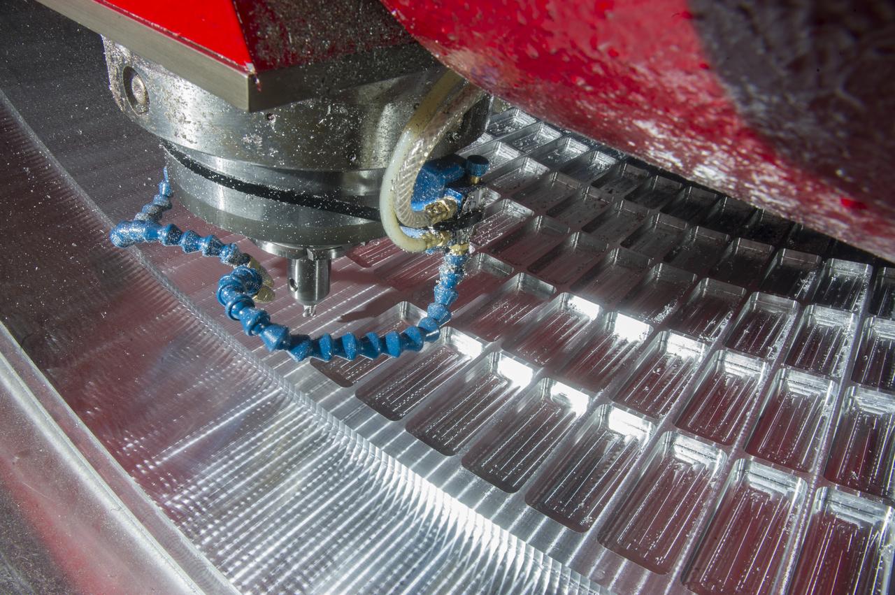
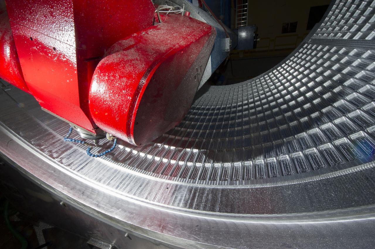
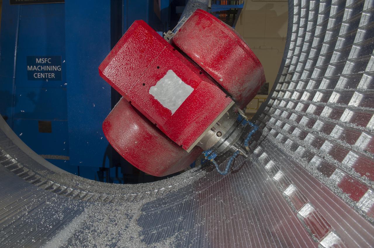
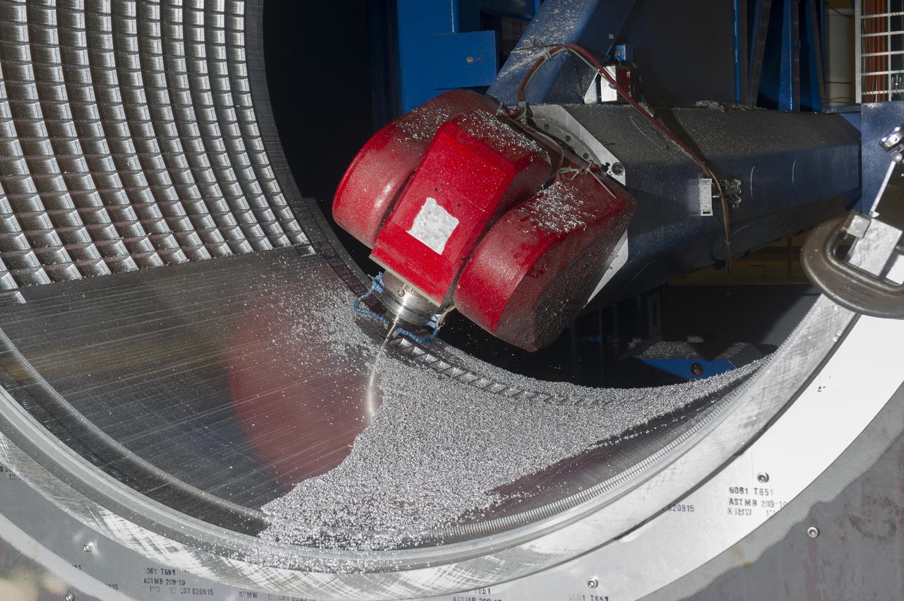
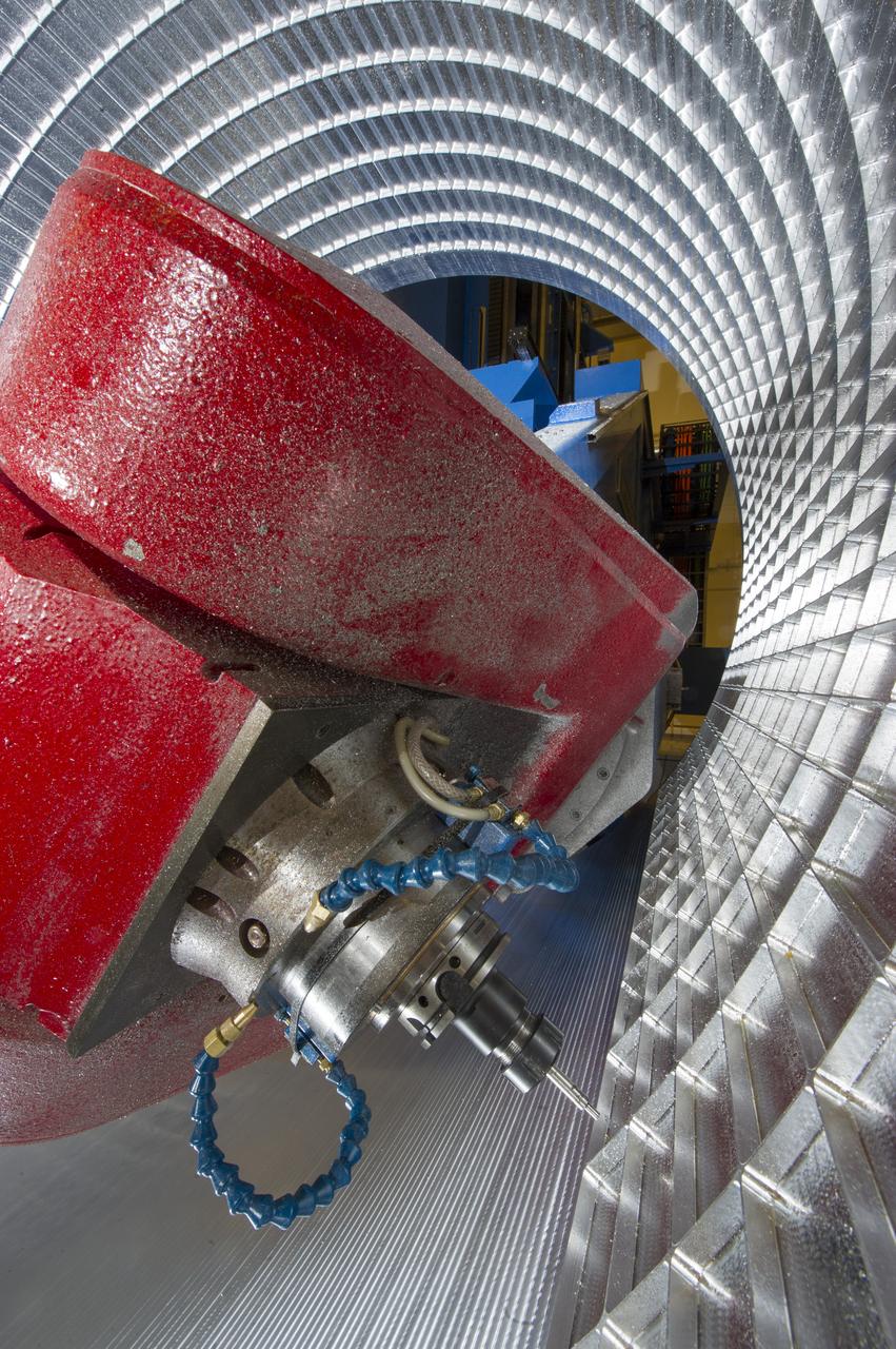
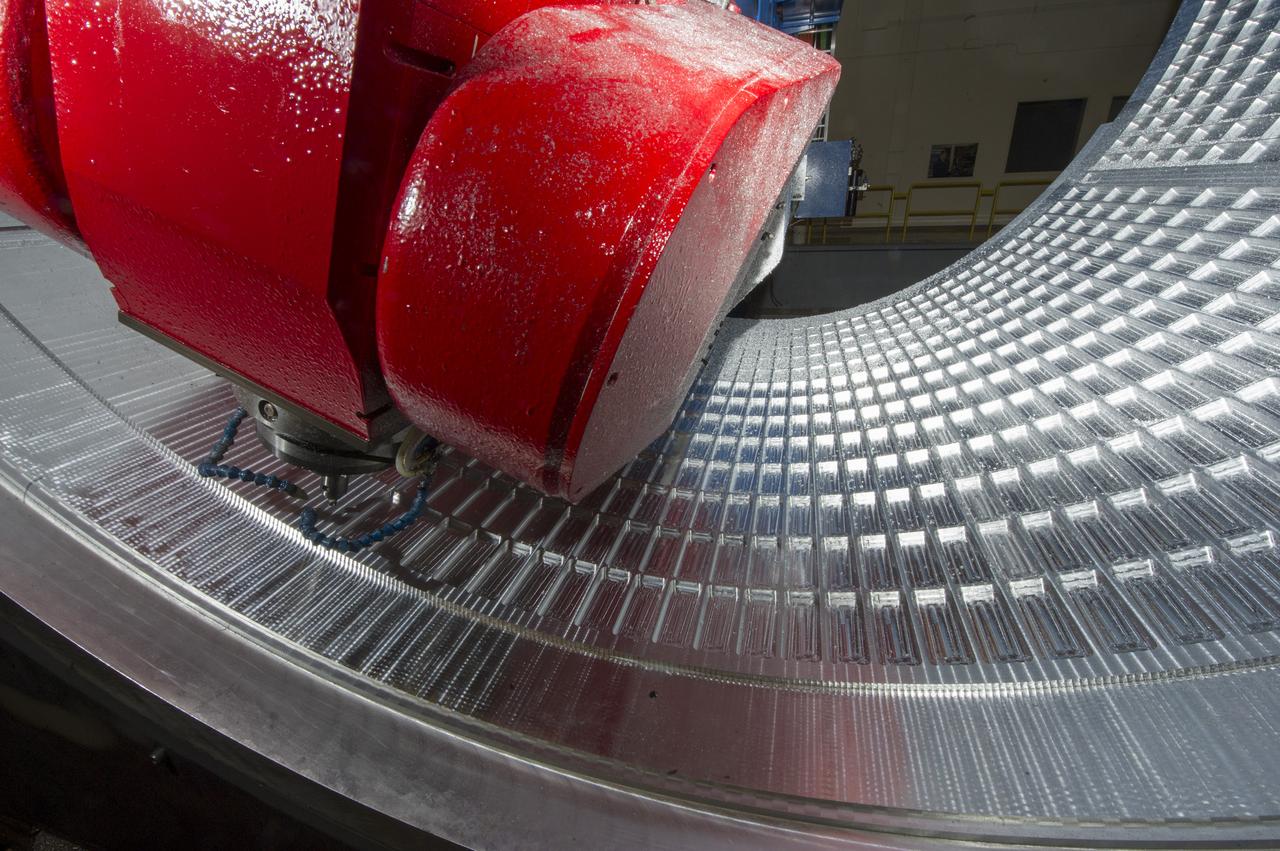
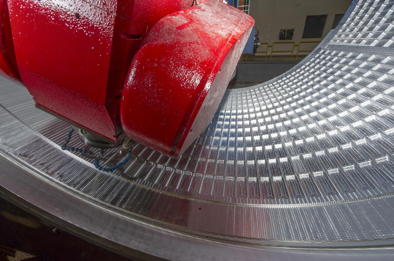
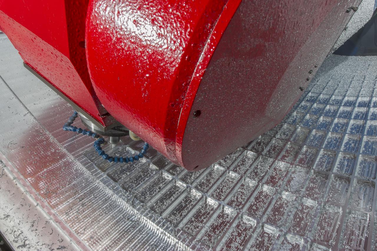
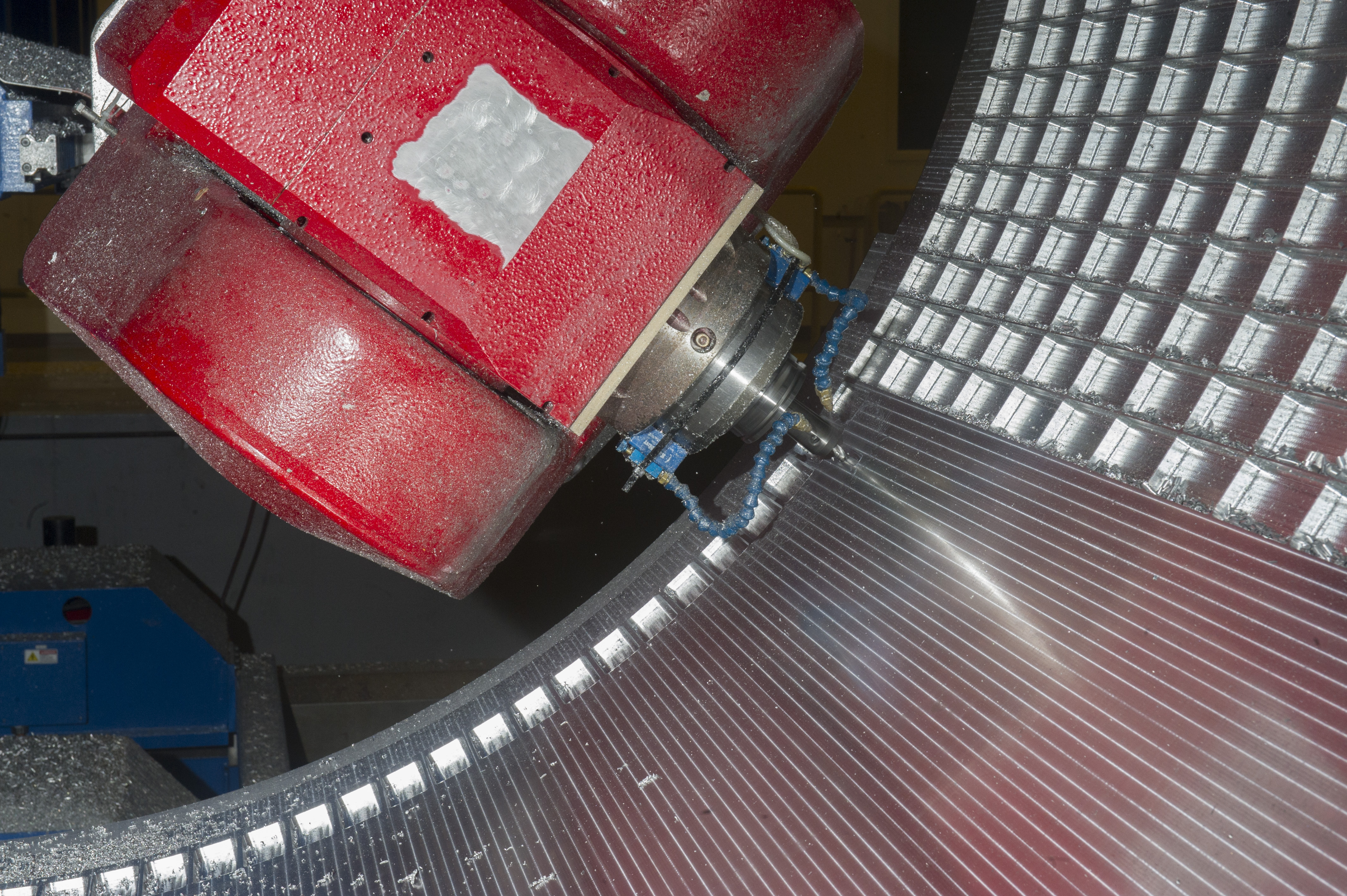
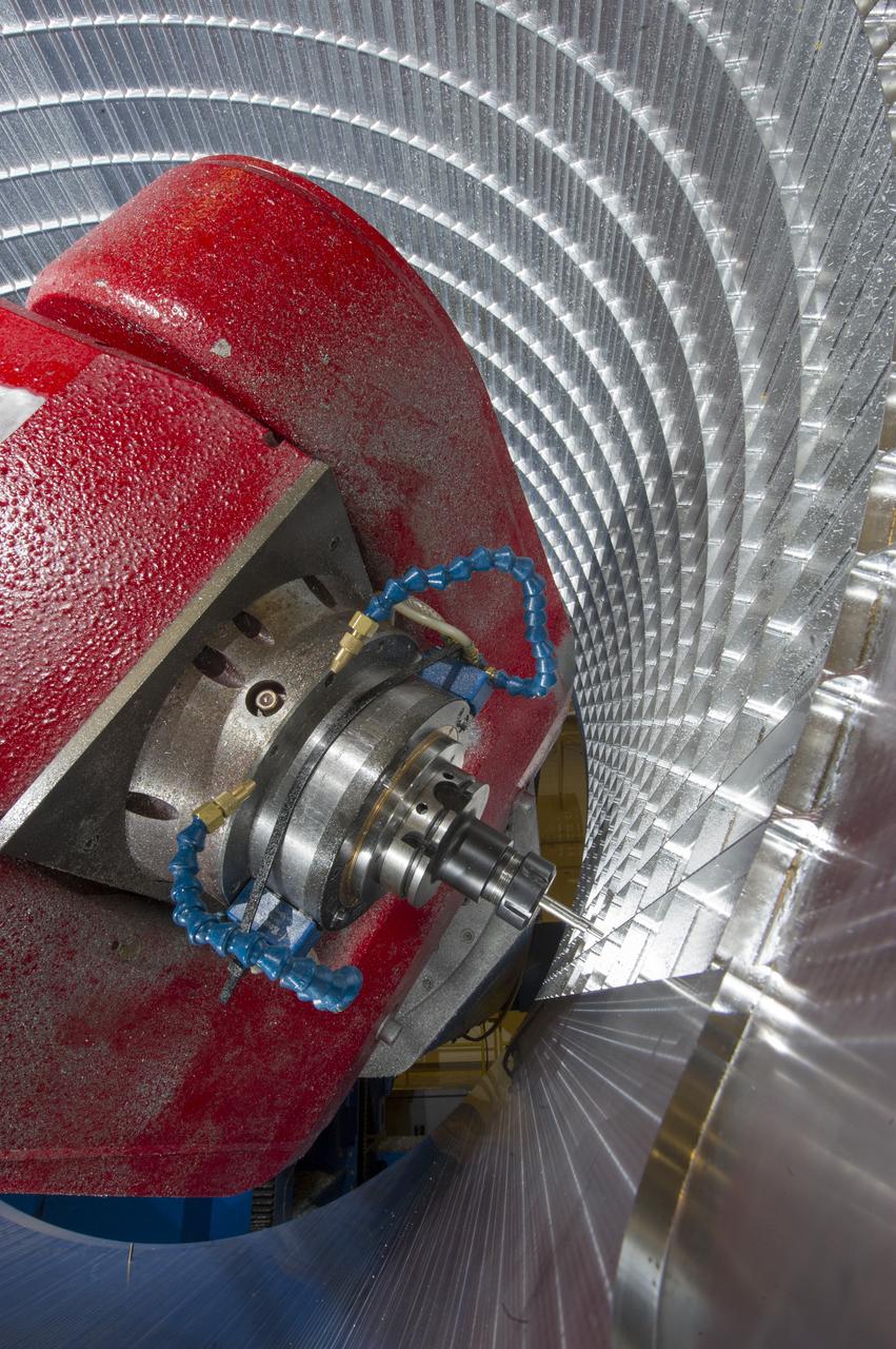
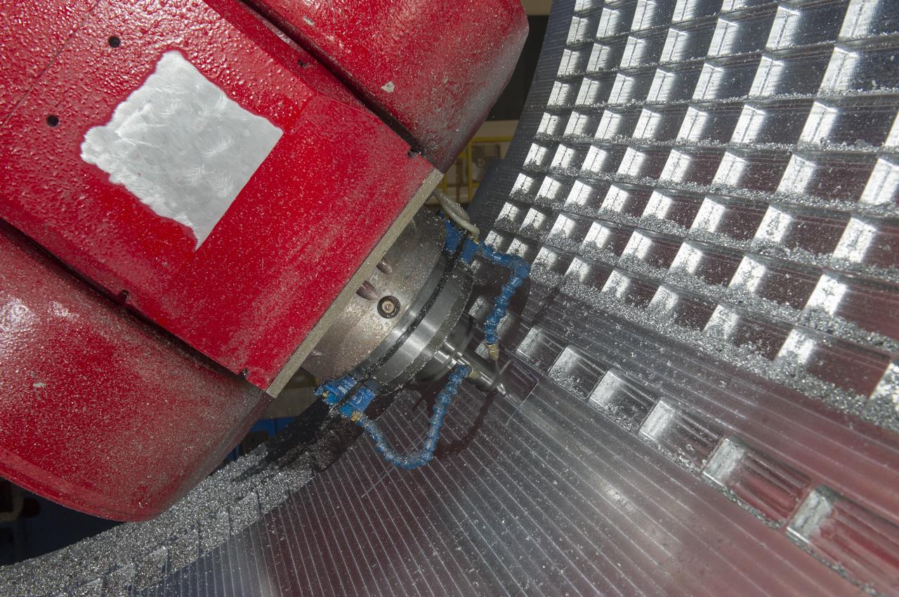
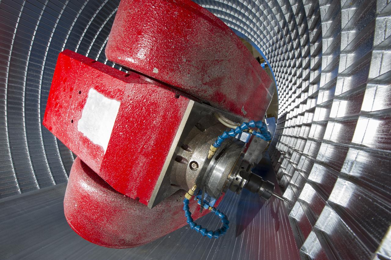
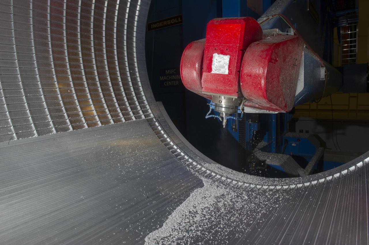
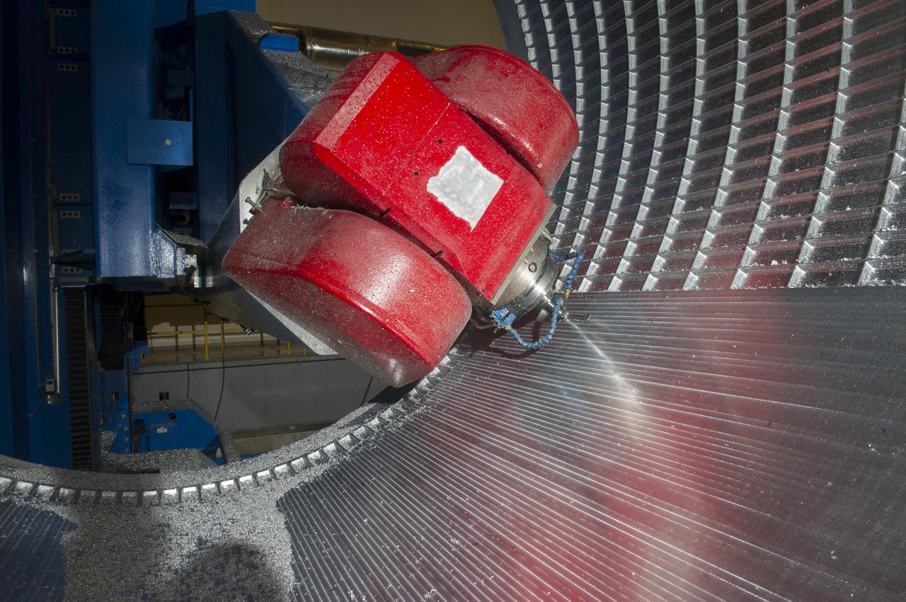
7-AXIS MILLING MACHINE CUTS ORTHOGRID TOOL PATH ON 8 FOOT CF1 BARREL IN SUPPORT OF SHELL BUCKLE TESTING
7-AXIS MILLING MACHINE CUTS ORTHOGRID TOOL PATH ON 8 FOOT CF1 BARREL IN SUPPORT OF SHELL BUCKLE TESTING
7-AXIS MILLING MACHINE CUTS ORTHOGRID TOOL PATH ON 8 FOOT CF1 BARREL IN SUPPORT OF SHELL BUCKLE TESTING
7-AXIS MILLING MACHINE CUTS ORTHOGRID TOOL PATH ON 8 FOOT CF1 BARREL IN SUPPORT OF SHELL BUCKLE TESTING
7-AXIS MILLING MACHINE CUTS ORTHOGRID TOOL PATH ON 8 FOOT CF1 BARREL IN SUPPORT OF SHELL BUCKLE TESTING
7-AXIS MILLING MACHINE CUTS ORTHOGRID TOOL PATH ON 8 FOOT CF1 BARREL IN SUPPORT OF SHELL BUCKLE TESTING
7-AXIS MILLING MACHINE CUTS ORTHOGRID TOOL PATH ON 8 FOOT CF1 BARREL IN SUPPORT OF SHELL BUCKLE TESTING
7-AXIS MILLING MACHINE CUTS ORTHOGRID TOOL PATH ON 8 FOOT CF1 BARREL IN SUPPORT OF SHELL BUCKLE TESTING
7-AXIS MILLING MACHINE CUTS ORTHOGRID TOOL PATH ON 8 FOOT CF1 BARREL IN SUPPORT OF SHELL BUCKLE TESTING
MARK MITCHELL WITH SOROTEK SYSTEM SUPPORTS LOW LEVEL CONTAMINATION APPLICATION FOR BOND SENSITIVITY TESTING.
7-AXIS MILLING MACHINE CUTS ORTHOGRID TOOL PATH ON 8 FOOT CF1 BARREL IN SUPPORT OF SHELL BUCKLE TESTING
7-AXIS MILLING MACHINE CUTS ORTHOGRID TOOL PATH ON 8 FOOT CF1 BARREL IN SUPPORT OF SHELL BUCKLE TESTING
7-AXIS MILLING MACHINE CUTS ORTHOGRID TOOL PATH ON 8 FOOT CF1 BARREL IN SUPPORT OF SHELL BUCKLE TESTING
7-AXIS MILLING MACHINE CUTS ORTHOGRID TOOL PATH ON 8 FOOT CF1 BARREL IN SUPPORT OF SHELL BUCKLE TESTING
Proctor & Gamble ACE-M-1 Sample Test Operations in the Telescience Support Center, TSC
7-AXIS MILLING MACHINE CUTS ORTHOGRID TOOL PATH ON 8 FOOT CF1 BARREL IN SUPPORT OF SHELL BUCKLE TESTING
7-AXIS MILLING MACHINE CUTS ORTHOGRID TOOL PATH ON 8 FOOT CF1 BARREL IN SUPPORT OF SHELL BUCKLE TESTING
7-AXIS MILLING MACHINE CUTS ORTHOGRID TOOL PATH ON 8 FOOT CF1 BARREL IN SUPPORT OF SHELL BUCKLE TESTING
7-AXIS MILLING MACHINE CUTS ORTHOGRID TOOL PATH ON 8 FOOT CF1 BARREL IN SUPPORT OF SHELL BUCKLE TESTING
7-AXIS MILLING MACHINE CUTS ORTHOGRID TOOL PATH ON 8 FOOT CF1 BARREL IN SUPPORT OF SHELL BUCKLE TESTING
7-AXIS MILLING MACHINE CUTS ORTHOGRID TOOL PATH ON 8 FOOT CF1 BARREL IN SUPPORT OF SHELL BUCKLE TESTING
7-AXIS MILLING MACHINE CUTS ORTHOGRID TOOL PATH ON 8 FOOT CF1 BARREL IN SUPPORT OF SHELL BUCKLE TESTING

7-AXIS MILLING MACHINE CUTS ORTHOGRID TOOL PATH ON 8 FOOT CF1 BARREL IN SUPPORT OF SHELL BUCKLE TESTING
7-AXIS MILLING MACHINE CUTS ORTHOGRID TOOL PATH ON 8 FOOT CF1 BARREL IN SUPPORT OF SHELL BUCKLE TESTING
7-AXIS MILLING MACHINE CUTS ORTHOGRID TOOL PATH ON 8 FOOT CF1 BARREL IN SUPPORT OF SHELL BUCKLE TESTING
7-AXIS MILLING MACHINE CUTS ORTHOGRID TOOL PATH ON 8 FOOT CF1 BARREL IN SUPPORT OF SHELL BUCKLE TESTING
7-AXIS MILLING MACHINE CUTS ORTHOGRID TOOL PATH ON 8 FOOT CF1 BARREL IN SUPPORT OF SHELL BUCKLE TESTING
7-AXIS MILLING MACHINE CUTS ORTHOGRID TOOL PATH ON 8 FOOT CF1 BARREL IN SUPPORT OF SHELL BUCKLE TESTING
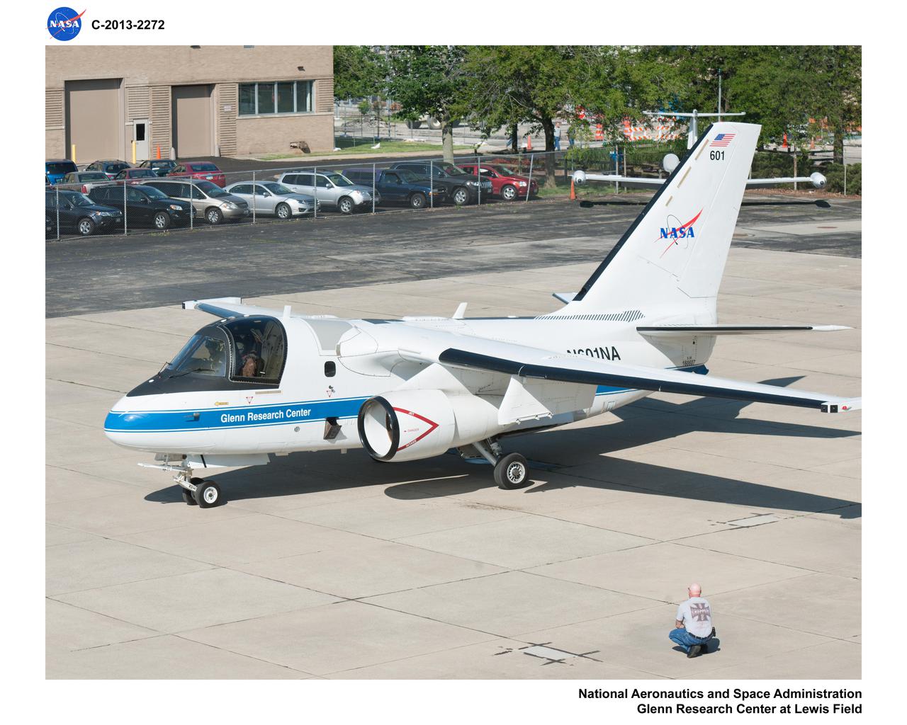
Lockheed S-3B Vikig Aircraft prepares for departure during testing in support of the Unmanned Aircraft Communications Project
7-AXIS MILLING MACHINE CUTS ORTHOGRID TOOL PATH ON 8 FOOT CF1 BARREL IN SUPPORT OF SHELL BUCKLE TESTING
7-AXIS MILLING MACHINE CUTS ORTHOGRID TOOL PATH ON 8 FOOT CF1 BARREL IN SUPPORT OF SHELL BUCKLE TESTING
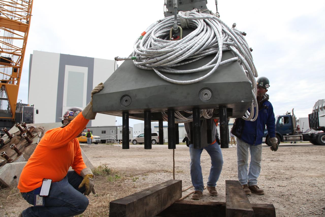
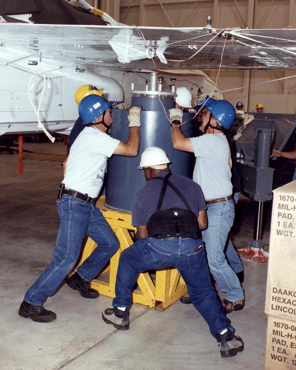
Construction workers assist as a crane is used to lower a vertical support post for NASA's Space Launch System (SLS) onto a platform at the Mobile Launcher Yard at NASA's Kennedy Space Center in Florida. Two ASEUs and the first of the vertical support posts underwent a series of tests at the Launch Equipment Test Facility to confirm they are functioning properly and ready to support the SLS for launch. The ASEUs will connect to the SLS rocket at the bottom outer edge of each booster and provide electrical power and data connections to the rocket until it lifts off from the launch pad. The eight VSPs will support the load of the solid rocket boosters, with four posts for each of the boosters. The center’s Engineering Directorate and the Ground Systems Development and Operations Program are overseeing processing and testing of the umbilicals.
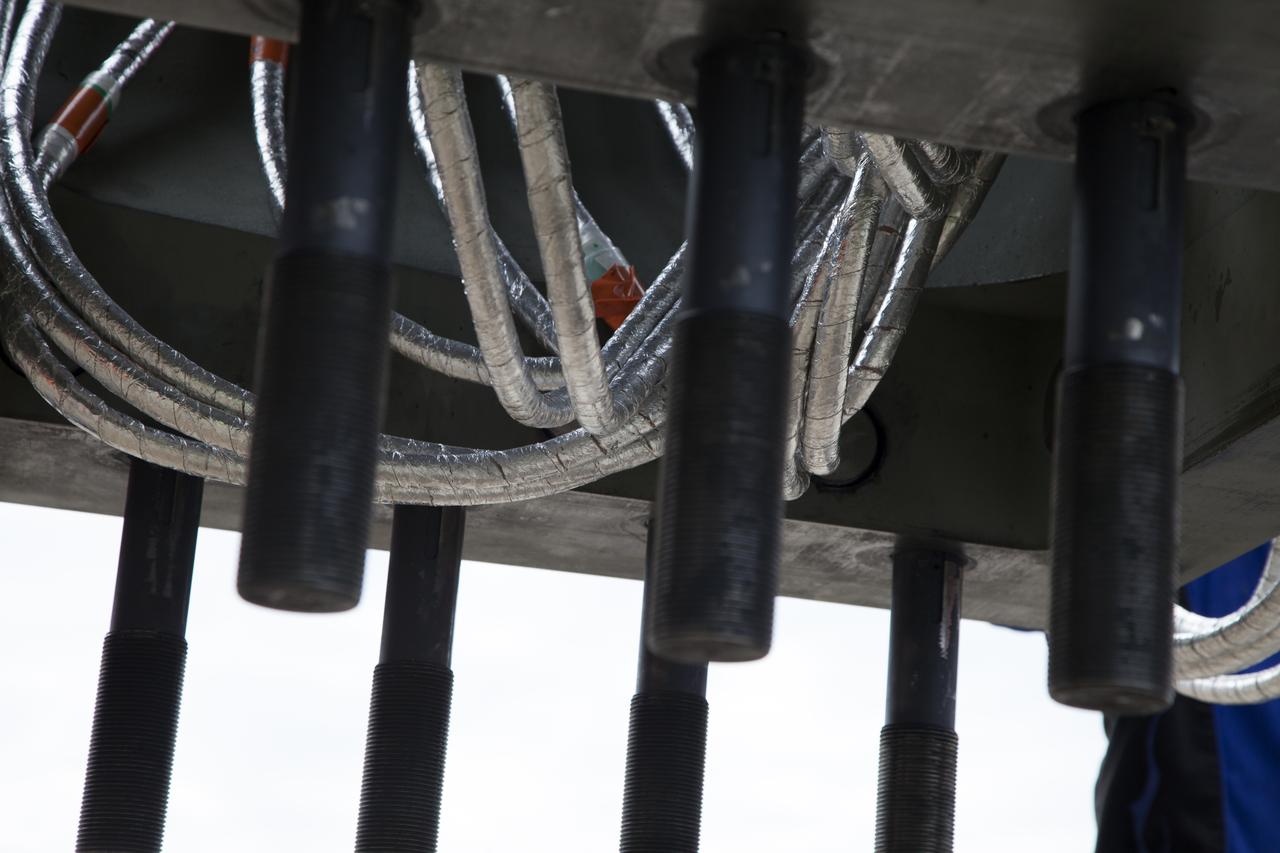
A view from underneath one of the vertical support posts for NASA's Space Launch System rocket. Two after skirt electrical umbilicals (ASEUs) and the first of the vertical support post were transported by flatbed truck from the Launch Equipment Test Facility to the Mobile Launcher Yard as NASA's Kennedy Space Center in Florida. The ASEUs and the VSP underwent a series of tests to confirm they are functioning properly and ready to support the SLS for launch. The ASEUs will connect to the SLS rocket at the bottom outer edge of each booster and provide electrical power and data connections to the rocket until it lifts off from the launch pad. The eight VSPs will support the load of the solid rocket boosters, with four posts for each of the boosters. The center’s Engineering Directorate and the Ground Systems Development and Operations Program are overseeing processing and testing of the umbilicals.
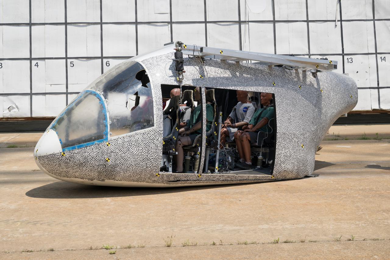
An aircraft body modeled after an air taxi with weighted test dummies inside is shown after a drop test at NASA’s Langley Research Center in Hampton, Virginia. The test was completed June 26 at Langley’s Landing and Impact Research Facility. The aircraft was dropped from a tall steel structure, known as a gantry, after being hoisted about 35 feet in the air by cables. NASA researchers are investigating aircraft materials that best absorb impact forces in a crash.

An aircraft body modeled after an air taxi with weighted test dummies inside is being prepared for a drop test by researchers at NASA’s Langley Research Center in Hampton, Virginia. The test was completed June 26 at Langley’s Landing and Impact Research Facility. The aircraft was dropped from a tall steel structure, known as a gantry, after being hoisted about 35 feet in the air by cables. NASA researchers are investigating aircraft materials that best absorb impact forces in a crash.
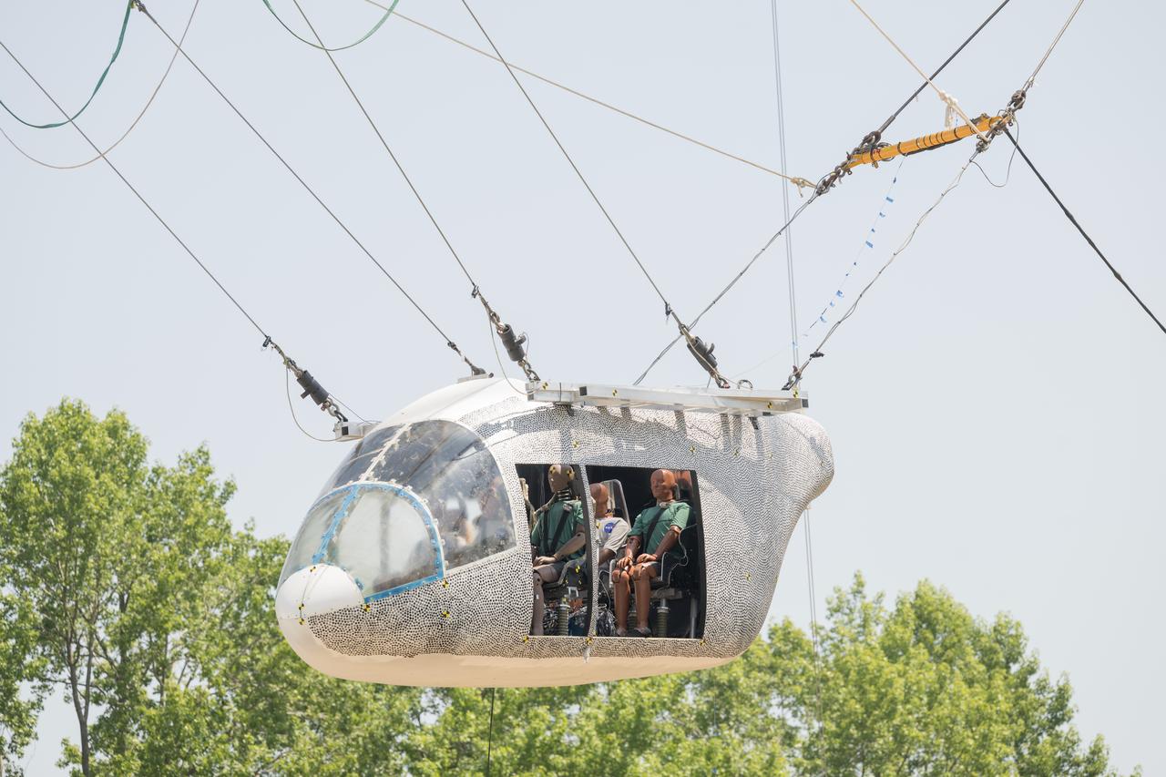
An aircraft body modeled after an air taxi with weighted test dummies inside is hoisted about 35 feet in the air by cables at NASA’s Langley Research Center in Hampton, Virginia. The aircraft was dropped from a tall steel structure, known as a gantry, on June 26 at Langley’s Landing and Impact Research Facility. NASA researchers are investigating aircraft materials that best absorb impact forces in a crash.
Shown is a test of the TEM-13 solid rocket motor at the ATK test facility in Utah in support of the Ares/CLV first stage. This image is extracted from high definition video and is the highest resolution available.
Shown is a wind tunnel test of the Ares model for force/moment testing in support of the Ares/ClV integrated vehicle at Langley Research Center, Virginia. The image is extracted from a high definition video file and is the highest resolution available.

The Space Environments Complex (SEC) at the Armstrong Testing Facility stores Orion’s Launch Abort System, which will later be tested for support of Artemis II. Photo Credit: (NASA/Jordan Salkin)
Shown is a wind tunnel test of the Ares model for force/moment testing in support of the Ares/Clv integrated vehicle at Langley Research Center, Virginia. The image is extracted from a high definition video file and is the highest resolution available.
NASA Dryden technicians (Dave Dennis, Freddy Green and Jeff Doughty) position a support cylinder under the right wing of the Active Aeroelastic Wing F/A-18 test aircraft prior to ground vibration tests.
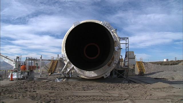
Shown is a test of the TEM-13 solid rocket motor at the ATK test facility in Utah in support of the Ares/CLV first stage. This image is extracted from high definition video and is the highest resolution available.
Shown is a wind tunnel test of the Ares model for force/moment testing in support of the Ares/ClV integrated vehicle at Langley Research Center, Virginia. The image is extracted from a high definition video file and is the highest resolution available.
Shown is a test of the TEM-13 solid rocket motor at the ATK test facility in Utah in support of the Ares/CLV first stage. This image is extracted from high definition video and is the highest resolution available.

The Space Environments Complex (SEC) at the Armstrong Testing Facility stores Orion’s Launch Abort System, which will later be tested for support of Artemis II. Photo Credit: (NASA/Jordan Salkin)

The communication antenna is used primarily for test flights to receive downlink flight data and video from test aircraft and also to support command uplink of data to test aircraft for command and control. It is one of two such assets of the Dryden Aeronautical Test Range at NASA’s Armstrong Flight Research Center in California.

The communication antenna is used primarily for test flights to receive downlink flight data and video from test aircraft and also to support command uplink of data to test aircraft for command and control. It is one of two such assets of the Dryden Aeronautical Test Range at NASA’s Armstrong Flight Research Center in California.
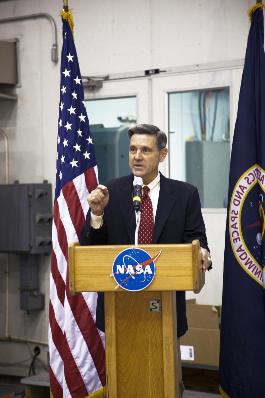
CAPE CANAVERAL, Fla. -- At NASA's Kennedy Space Center in Florida, Center Director Bob Cabana talks to workers at the Launch Equipment Test Facility (LETF), which recently underwent a $35 million comprehensive upgrade that lasted four years. The LETF was established in the 1970s to support the qualification of the Space Shuttle Program’s umbilical and T-0 mechanisms. Throughout the years, it has supported the development of systems for shuttle and the International Space Station, Delta and Atlas rockets, and various research and development programs. The LETF has unique capabilities to evolve into a versatile test and development area that supports a wide spectrum of programs. For information on NASA's future plans, visit www.nasa.gov. Photo credit: NASA/Dimitri Gerondidakis
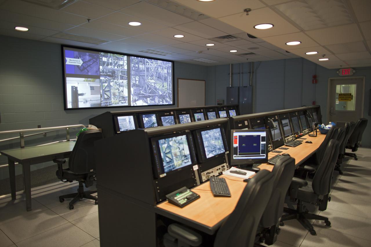
CAPE CANAVERAL, Fla. -- At NASA's Kennedy Space Center in Florida is the control room of the Launch Equipment Test Facility (LETF). The LETF recently underwent a $35 million comprehensive upgrade that lasted four years. The LETF was established in the 1970s to support the qualification of the Space Shuttle Program’s umbilical and T-0 mechanisms. Throughout the years, it has supported the development of systems for shuttle and the International Space Station, Delta and Atlas rockets, and various research and development programs. The LETF has unique capabilities to evolve into a versatile test and development area that supports a wide spectrum of programs. For information on NASA's future plans, visit www.nasa.gov. Photo credit: NASA/Dimitri Gerondidakis
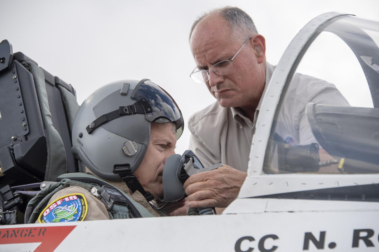
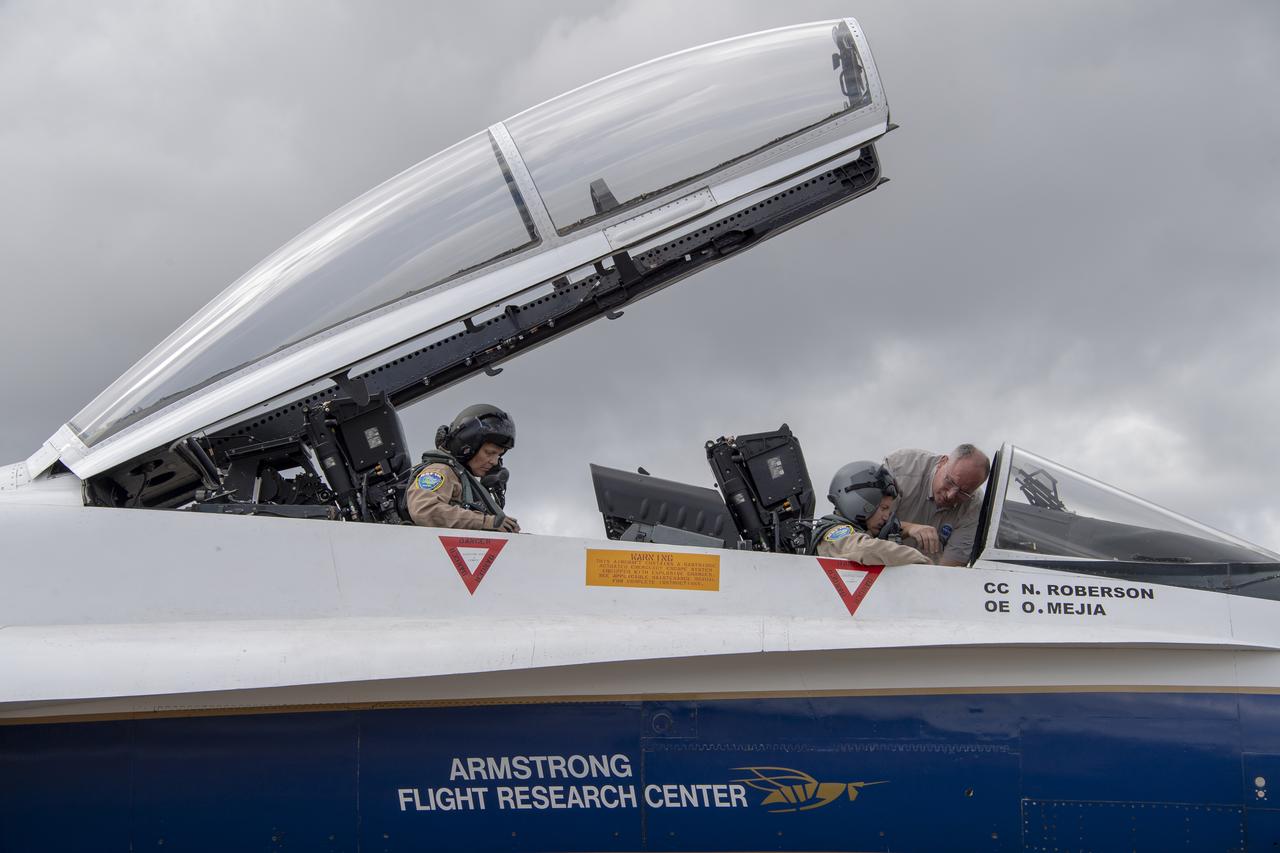
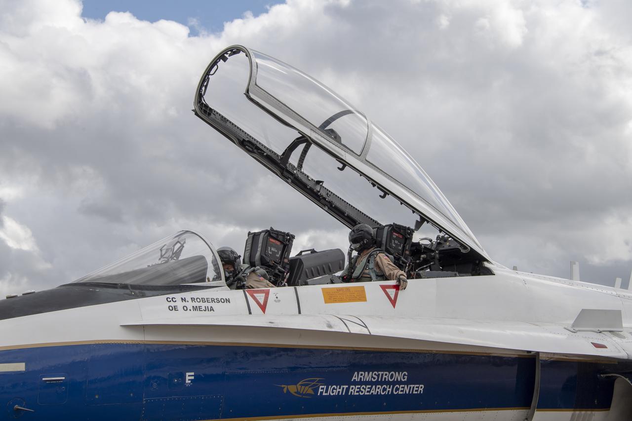
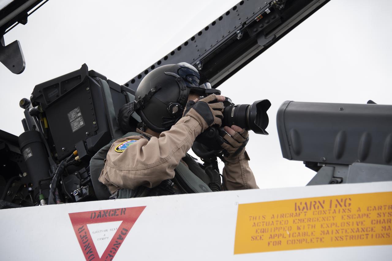
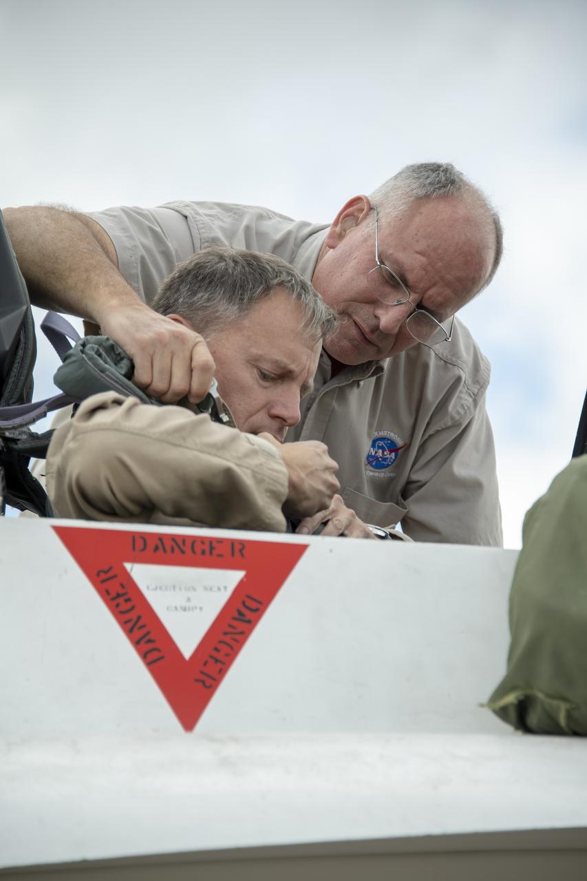
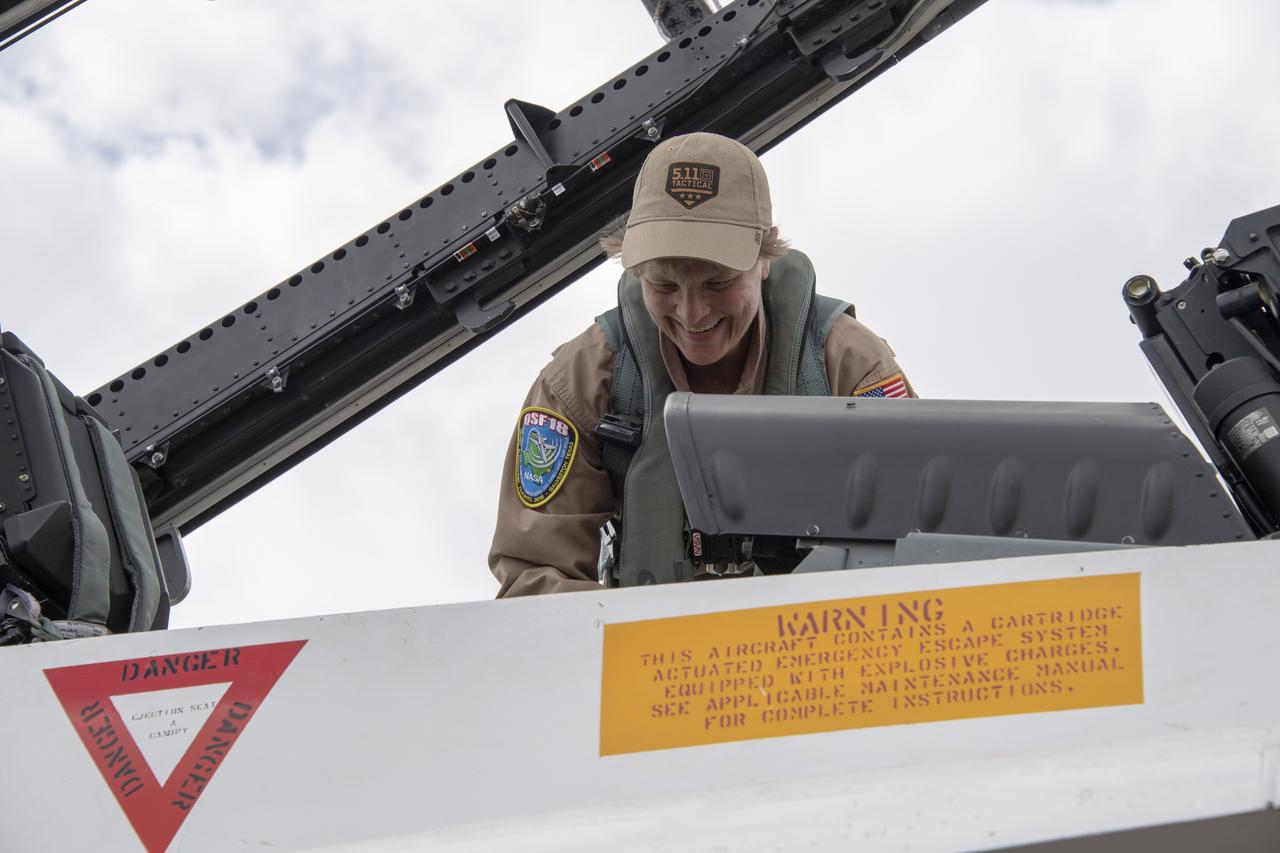
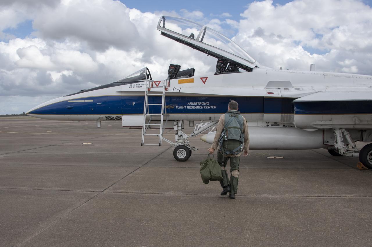
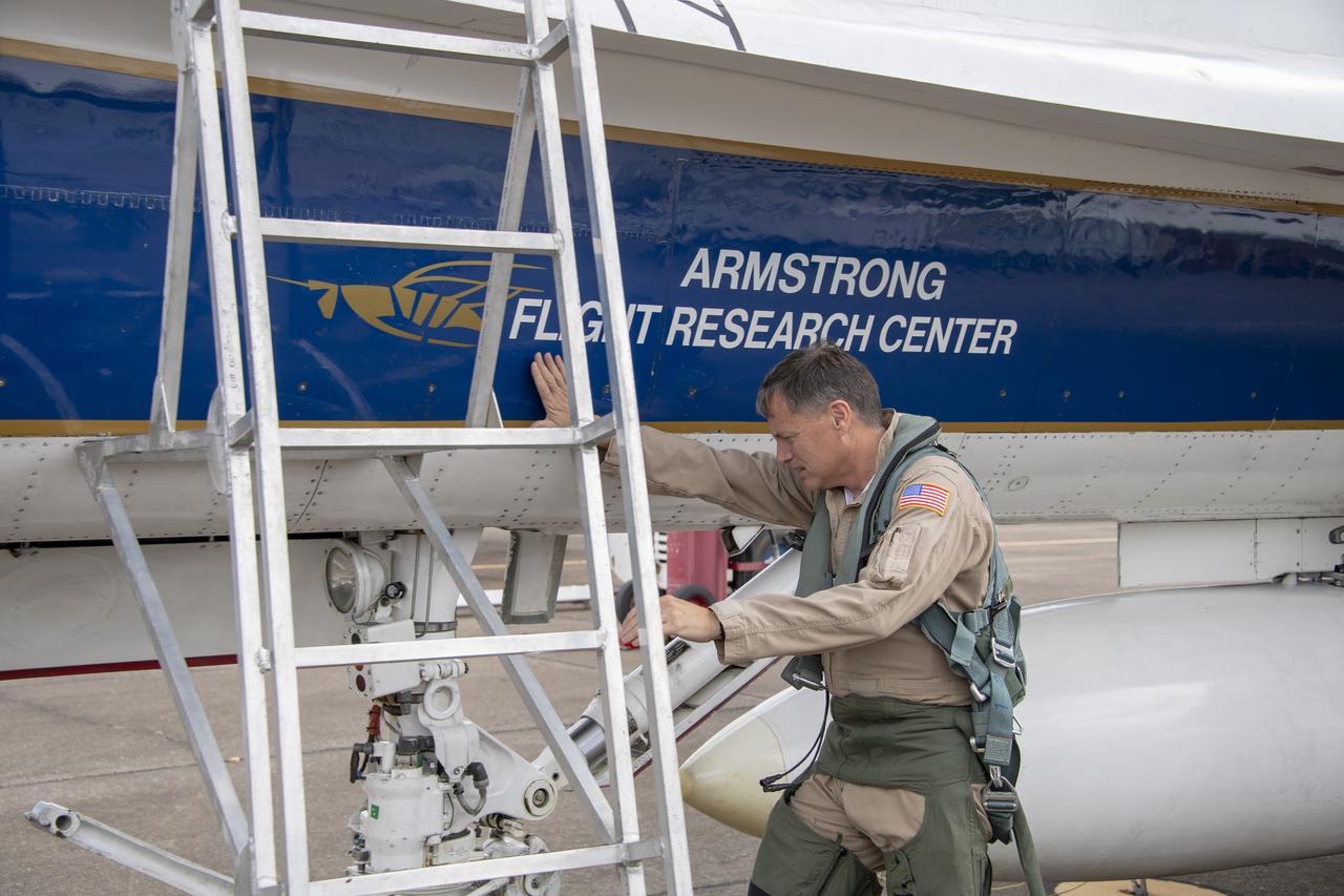
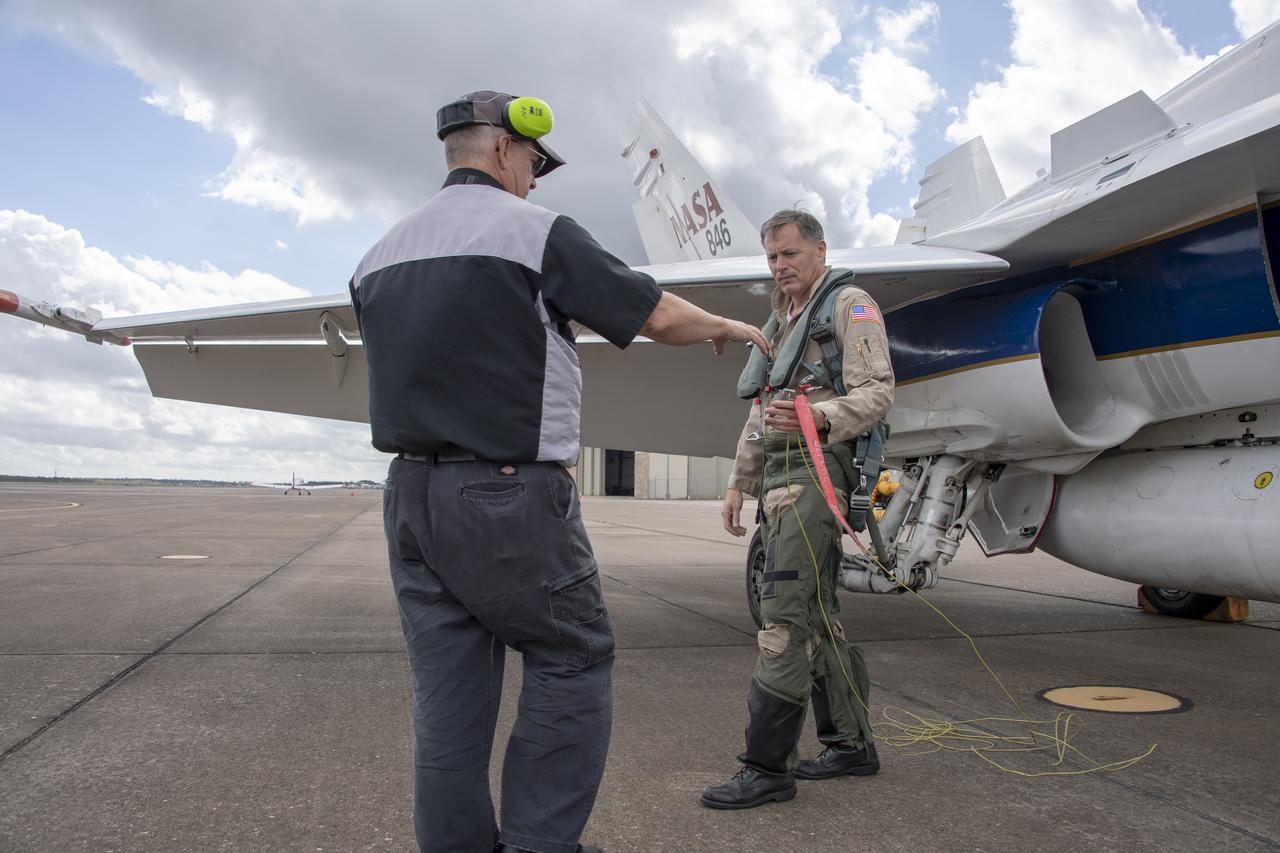
NASA test pilot Wayne “Ringo” Ringelberg and photographer Carla Thomas prepare to take off for a supersonic research flight in support of the QSF18 campaign off the coast of Texas. NASA photographers and videographers take part in operations to support mission documentation.
NASA test pilot Wayne “Ringo” Ringelberg and photographer Carla Thomas prepare to take off for a supersonic research flight in support of the QSF18 campaign off the coast of Texas. NASA photographers and videographers take part in operations to support mission documentation.
NASA test pilot Wayne “Ringo” Ringelberg and photographer Carla Thomas prepare to take off for a supersonic research flight in support of the QSF18 campaign off the coast of Texas. NASA photographers and videographers take part in operations to support mission documentation.
NASA test pilot Wayne “Ringo” Ringelberg and photographer Carla Thomas prepare to take off for a supersonic research flight in support of the QSF18 campaign off the coast of Texas. NASA photographers and videographers take part in operations to support mission documentation.
NASA test pilot Wayne “Ringo” Ringelberg and photographer Carla Thomas prepare to take off for a supersonic research flight in support of the QSF18 campaign off the coast of Texas. NASA photographers and videographers take part in operations to support mission documentation.

NASA test pilot Wayne “Ringo” Ringelberg and photographer Carla Thomas prepare to take off for a supersonic research flight in support of the QSF18 campaign off the coast of Texas. NASA photographers and videographers take part in operations to support mission documentation.
NASA test pilot Wayne “Ringo” Ringelberg and photographer Carla Thomas prepare to take off for a supersonic research flight in support of the QSF18 campaign off the coast of Texas. NASA photographers and videographers take part in operations to support mission documentation.
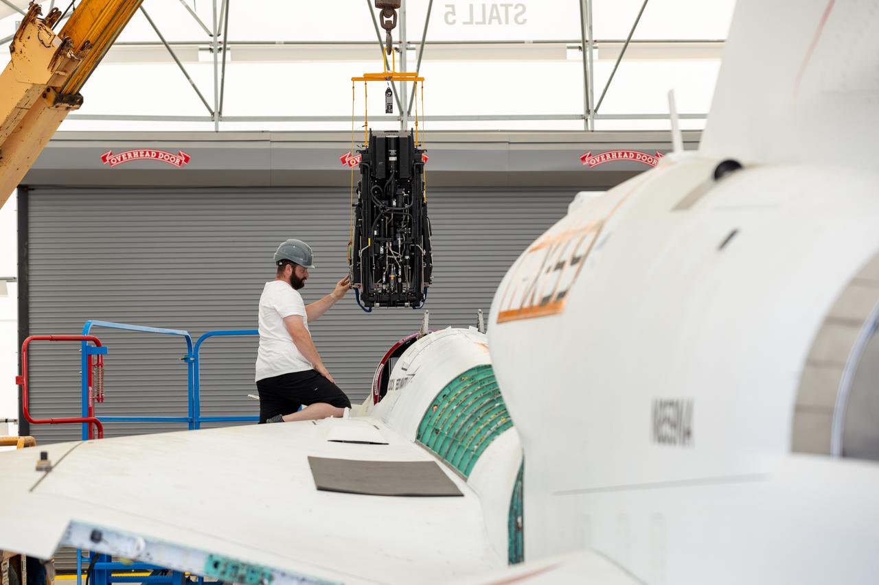
NASA Life Support Technician Mathew Sechler provides support as the X-59’s ejection seat is installed into the aircraft at Lockheed Martin Skunk Works’ facilities in Palmdale, California. Completion of the seat’s installation marks an integration milestone for the aircraft as it prepares for final ground tests.
NASA test pilot Wayne "Ringo" Ringelberg and photographer Carla Thomas prepare to take off for a supersonic research flight in support of the QSF18 campaign off the coast of Texas. NASA photographers and videographers take part in operations to support mission documentation.

NASA test pilot Wayne “Ringo” Ringelberg and photographer Carla Thomas prepare to take off for a supersonic research flight in support of the QSF18 campaign off the coast of Texas. NASA photographers and videographers take part in operations to support mission documentation.
NASA test pilot Wayne “Ringo” Ringelberg and photographer Carla Thomas prepare to take off for a supersonic research flight in support of the QSF18 campaign off the coast of Texas. NASA photographers and videographers take part in operations to support mission documentation.
NASA test pilot Wayne “Ringo” Ringelberg and photographer Carla Thomas prepare to take off for a supersonic research flight in support of the QSF18 campaign off the coast of Texas. NASA photographers and videographers take part in operations to support mission documentation.

NASA test pilot Wayne “Ringo” Ringelberg and photographer Carla Thomas prepare to take off for a supersonic research flight in support of the QSF18 campaign off the coast of Texas. NASA photographers and videographers take part in operations to support mission documentation.