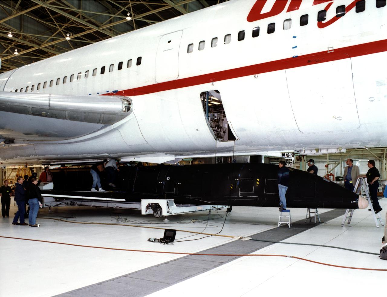
This is the X-34 Technology Testbed Demonstrator being mated with the L-1011 mothership. The X-34 will demonstrate key vehicle and operational technologies applicable to future low-cost resuable launch vehicles.
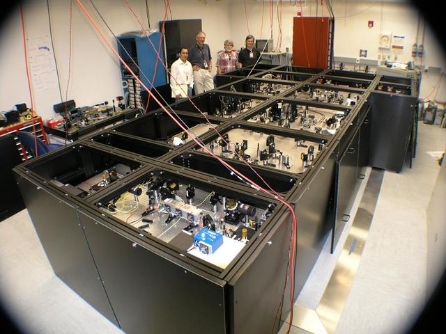
From left to right: JPLers Felipe Santos Fregoso, Piotr Szwaykowski, Kurt Liewer and Stefan Martin with the nulling interferometer testbed at JPL, where the device is built and refined.
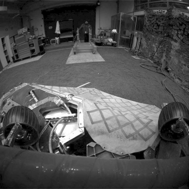
This image shows a test rover in a near-final turned position on the lander in NASA Jet Propulsion Laboratory In-Situ Instruments Laboratory, or testbed.

Airbags are fully inflated in this photograph taken at the JPL In-Situ Instrument Laboratory or Testbed, where engineers simulated the orientation of the airbags during the deflation process.
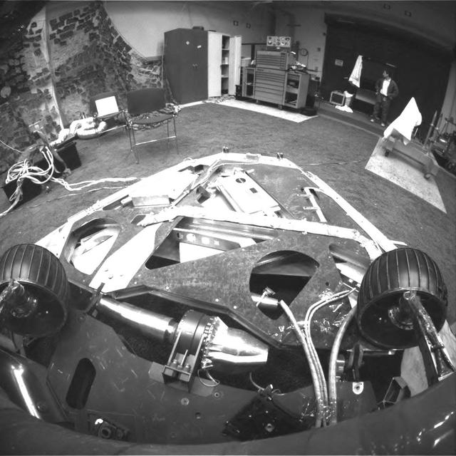
This image, taken in the JPL In-Situ Instruments Laboratory or Testbed, shows the view from the front hazard avoidance cameras on the Mars Exploration Rover Spirit after the rover has backed up and turned 45 degrees counterclockwise.
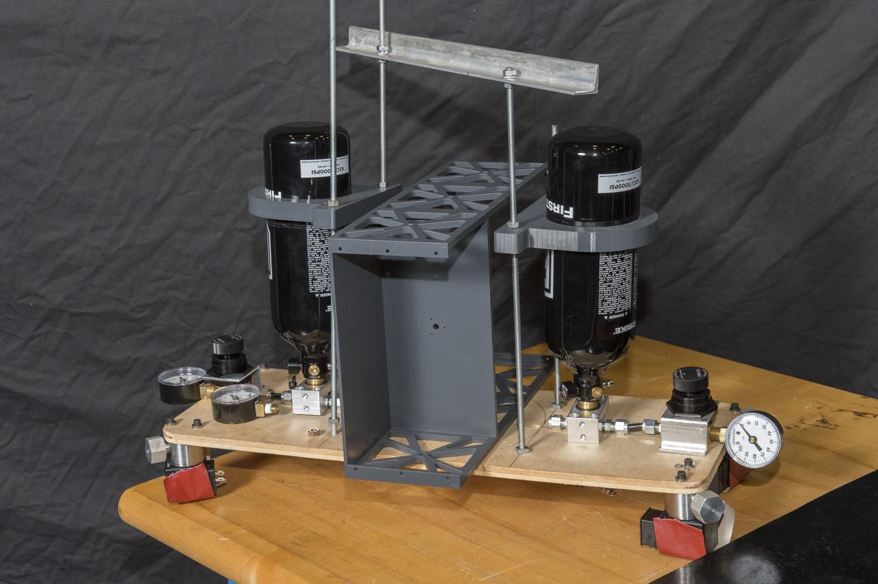
Second Generation Agile Engineering Prototype of Electric Sail 6U CubeSat Testbed Article
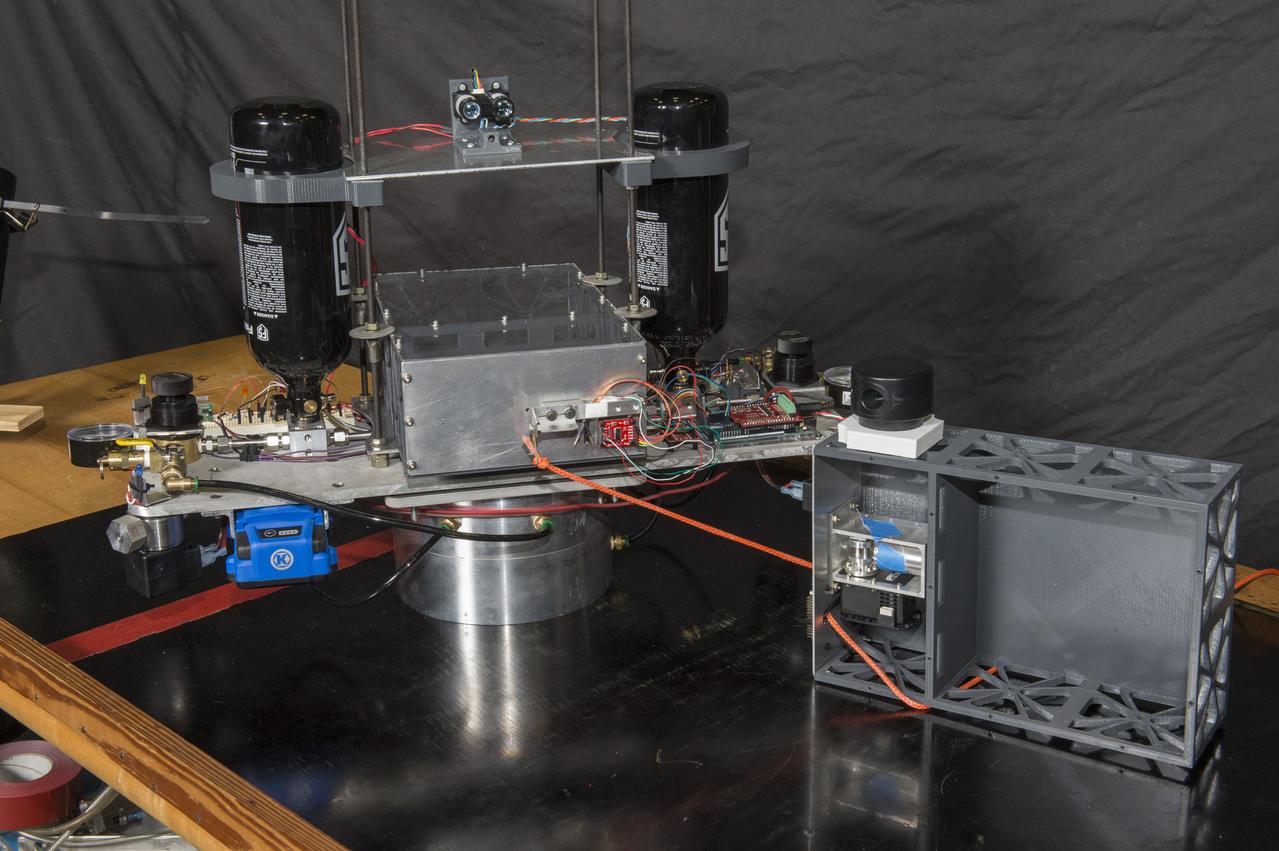
Electric Sail 6U CubeSat Testbed Article with Tether Mockup
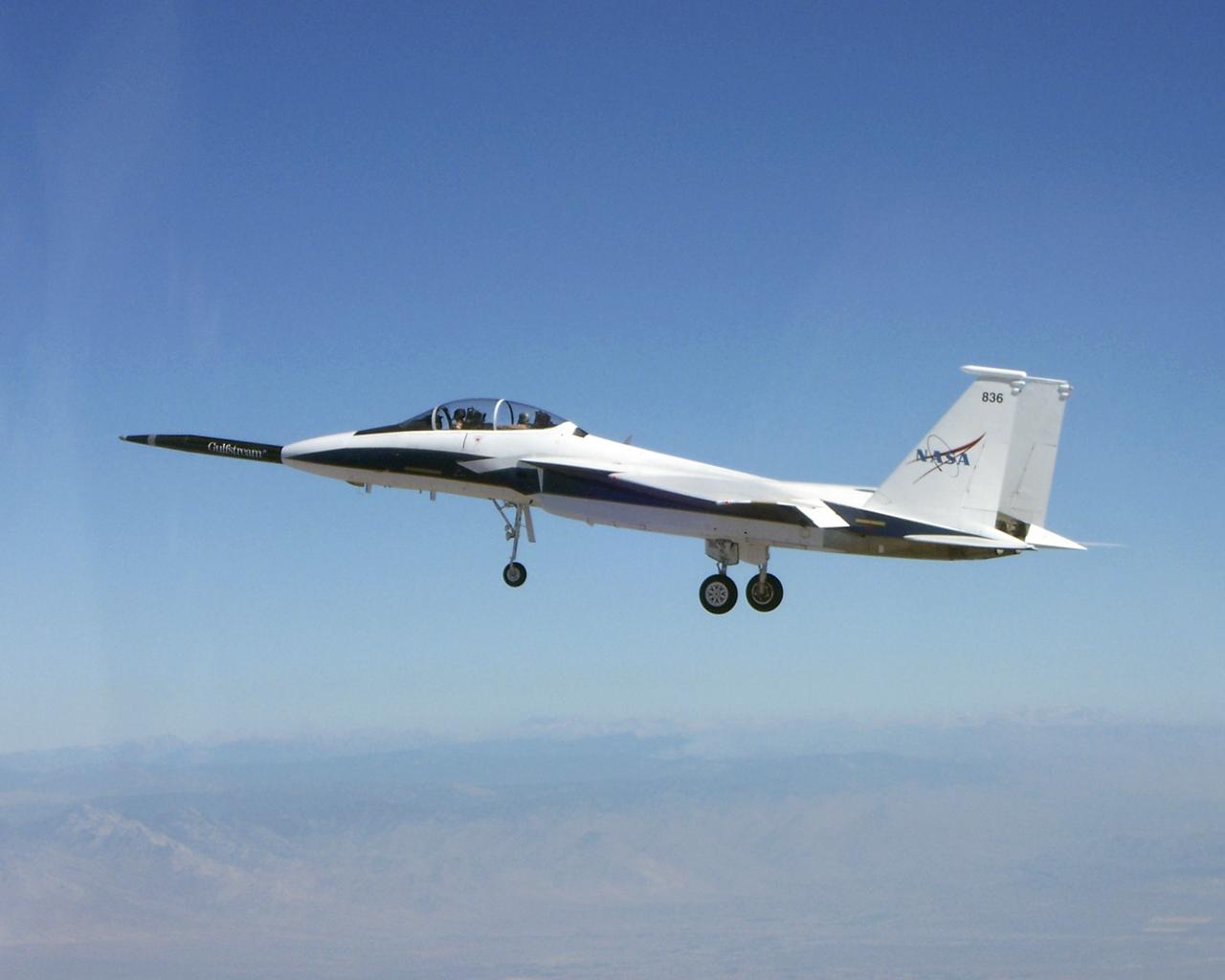
NASA's F-15B testbed aircraft in flight during the first evaluation flight of the joint NASA/Gulfstream Quiet Spike project. The project seeks to verify the structural integrity of the multi-segmented, articulating spike attachment designed to reduce and control a sonic boom.
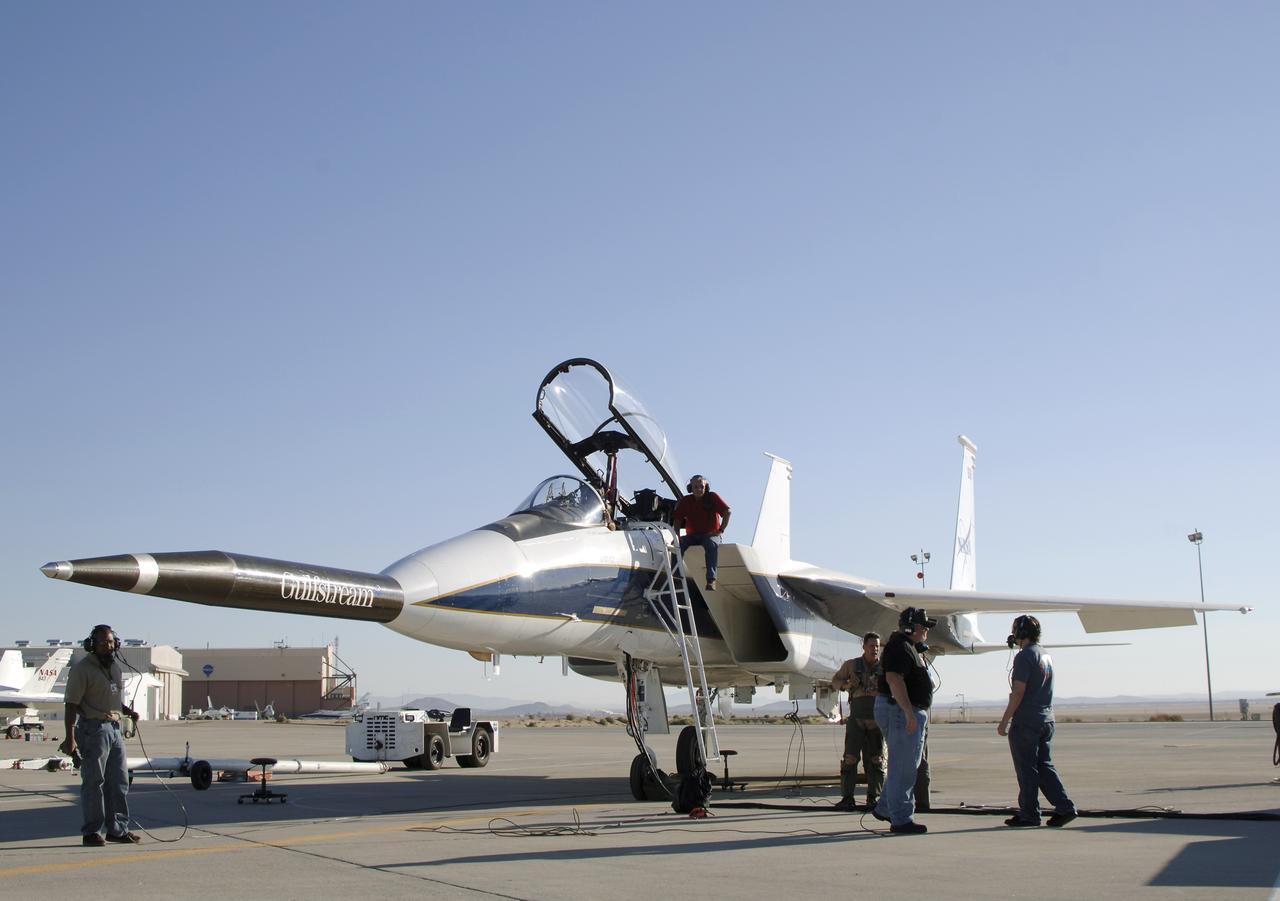
NASA's F-15B testbed aircraft undergoes pre-flight checks before performing the first flight of the Quiet Spike project. The first flight was performed for evaluation purposes, and the spike was not extended. The Quiet Spike was developed as a means of controlling and reducing the sonic boom caused by an aircraft 'breaking' the sound barrier.
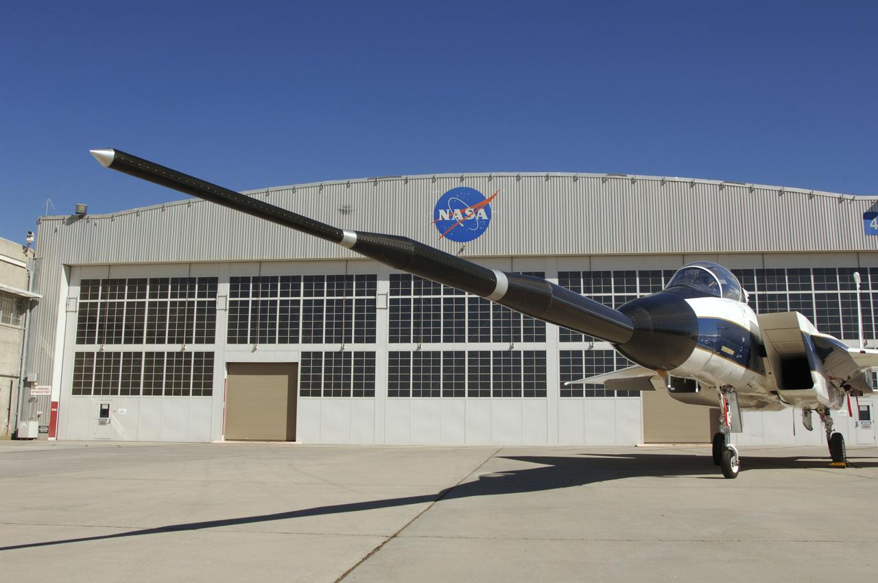
Gulfstream Aerospace and NASA's Dryden Flight Research Center are testing the structural integrity of a telescopic 'Quiet Spike' sonic boom mitigator on the F-15B testbed. The Quiet Spike was developed as a means of controlling and reducing the sonic boom caused by an aircraft 'breaking' the sound barrier.
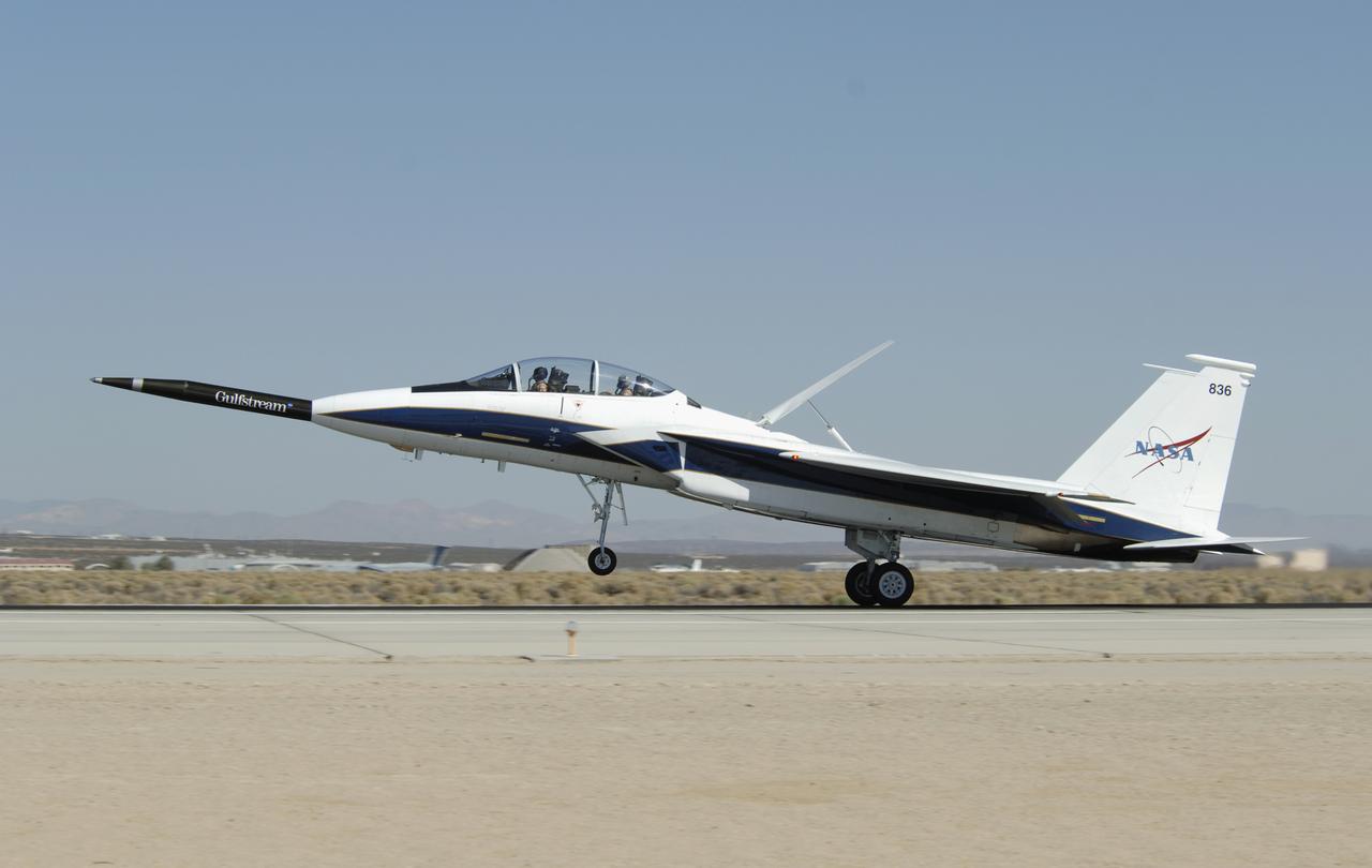
NASA's F-15B testbed aircraft lands after the first flight of the Quiet Spike project. The first flight was performed for evaluation purposes, and the spike was not extended. The Quiet Spike was developed as a means of controlling and reducing the sonic boom caused by an aircraft 'breaking' the sound barrier.
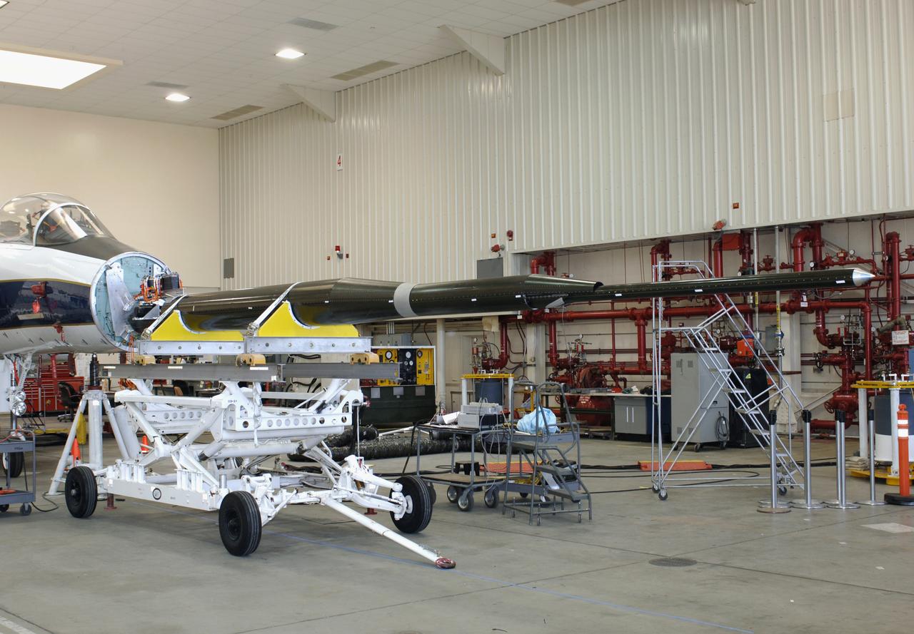
Gulfstream's Quiet Spike sonic boom mitigator being installed on NASA DFRC's F-15B testbed aircraft. The project seeks to verify the structural integrity of the multi-segmented, articulating spike attachment designed to reduce and control a sonic boom.
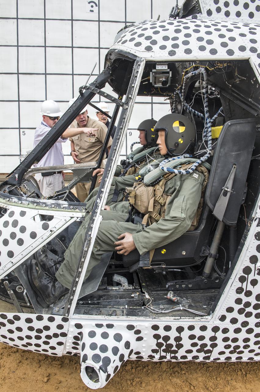
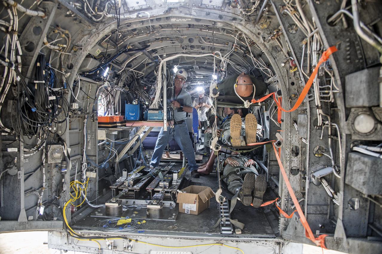
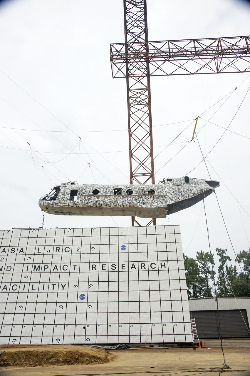
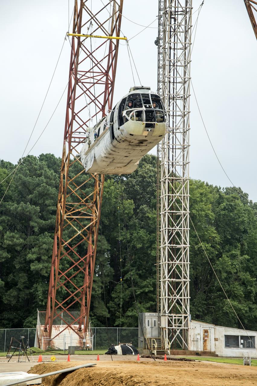
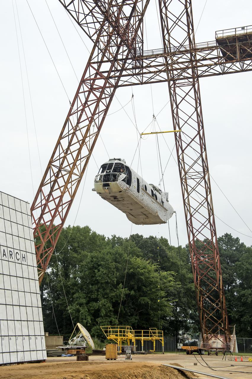
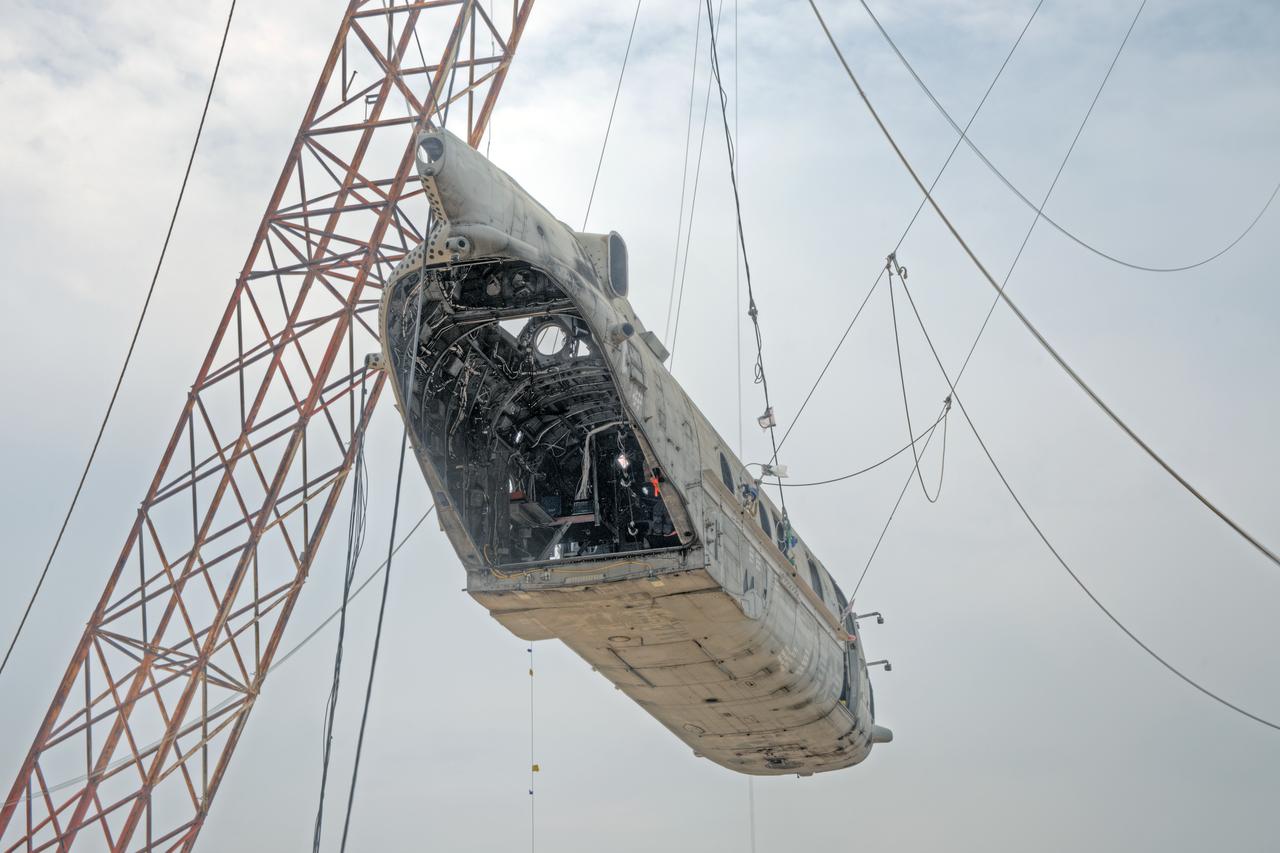
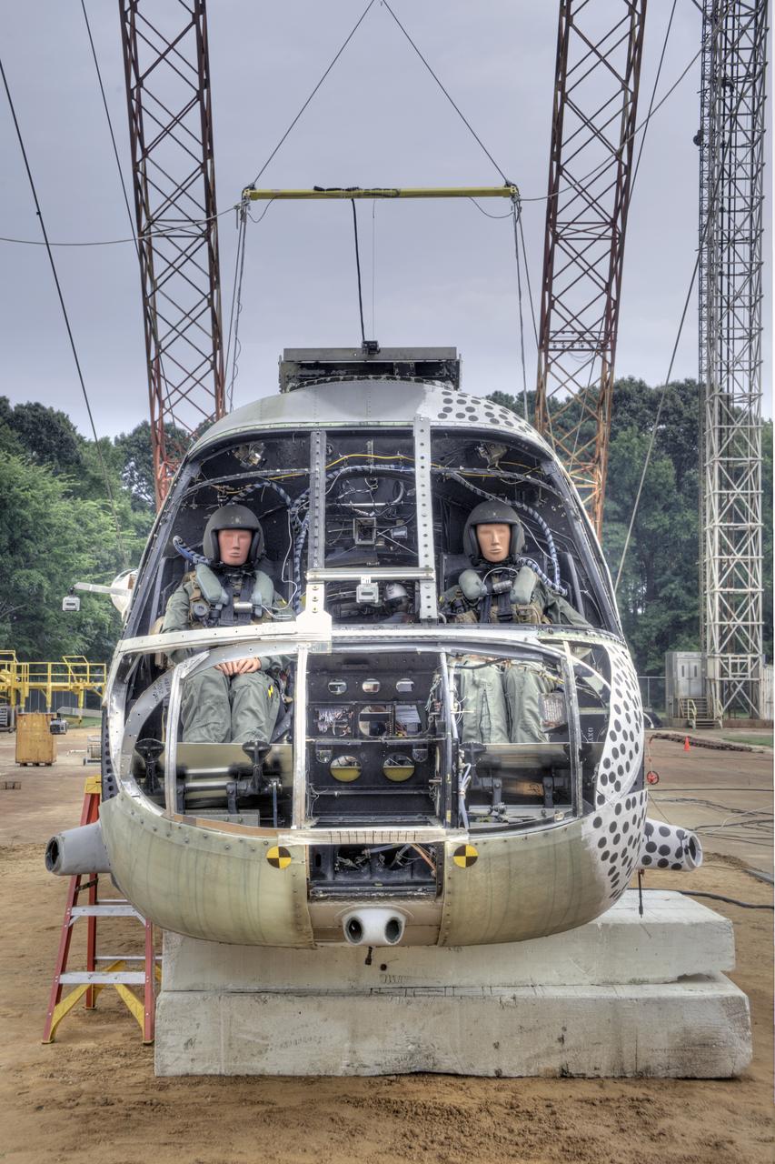
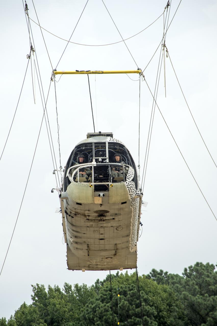
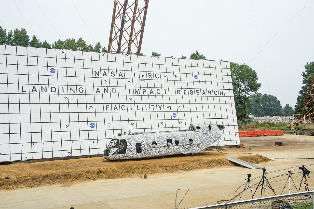
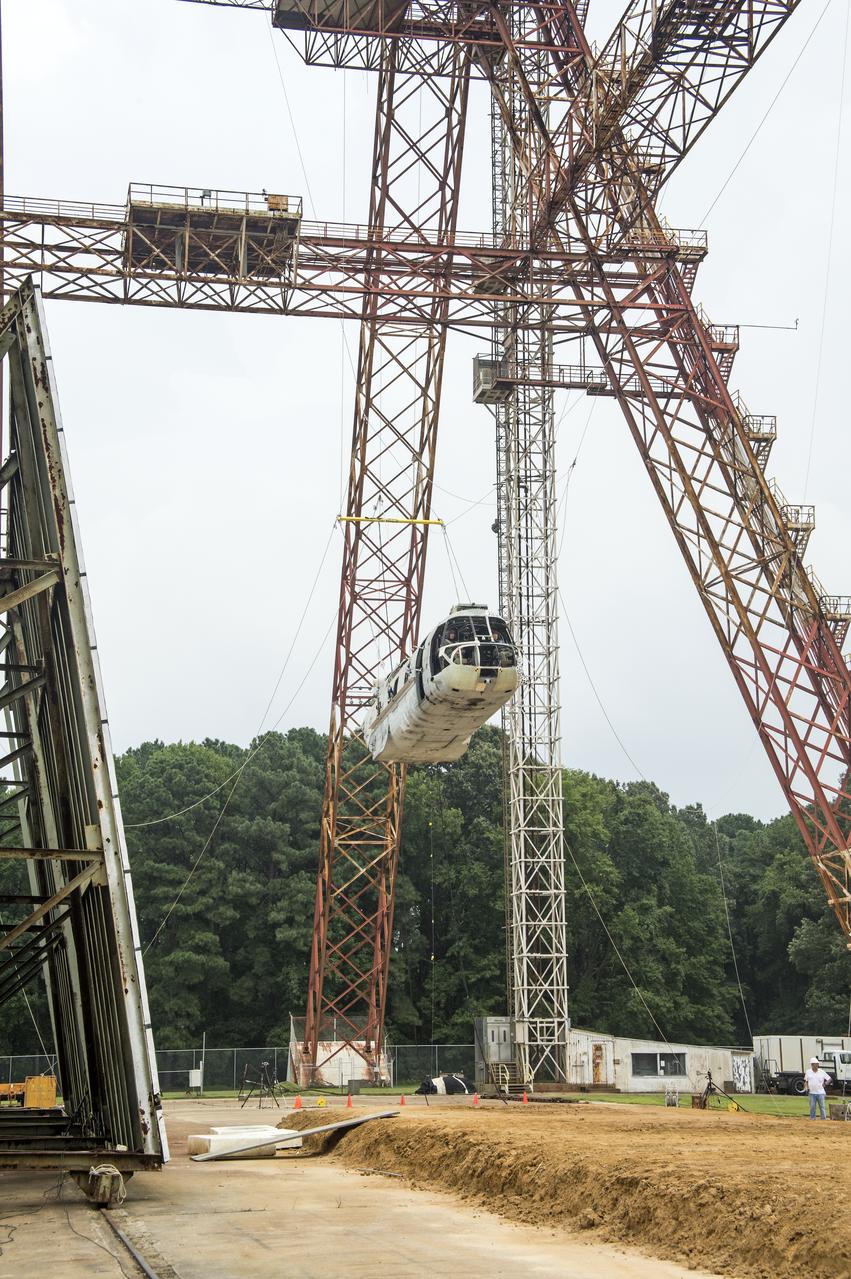
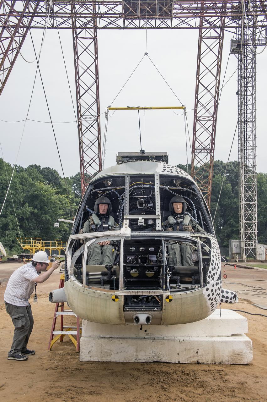
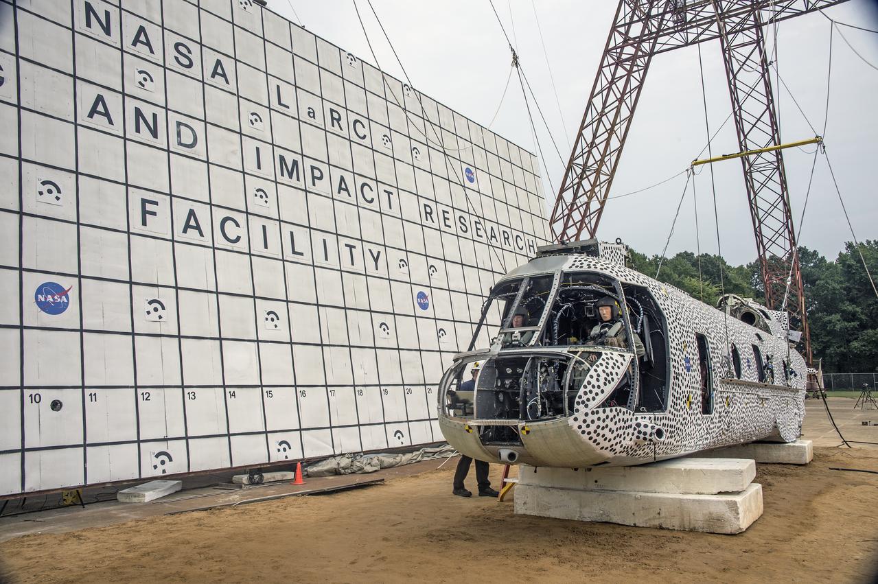
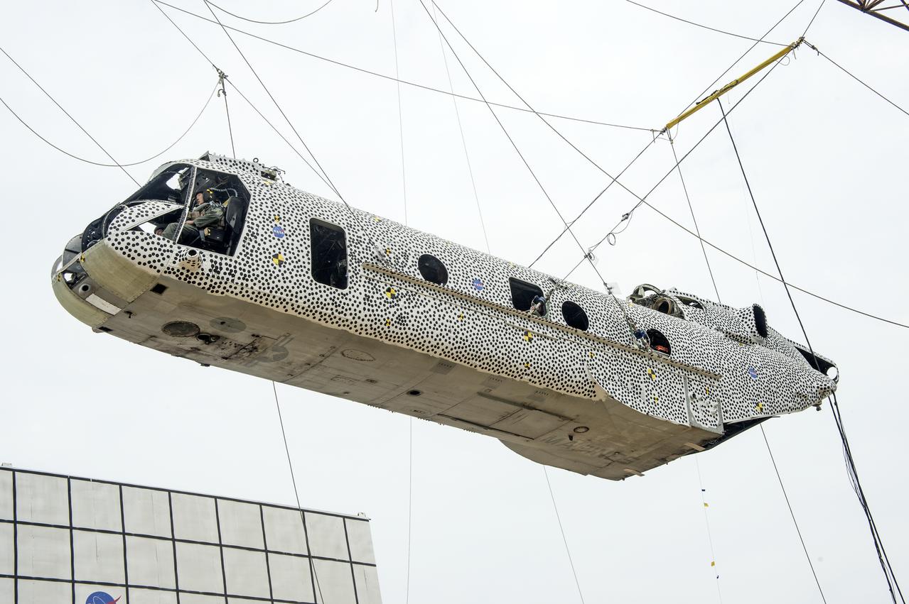
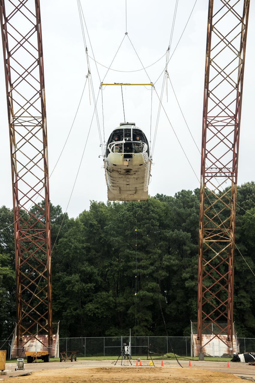
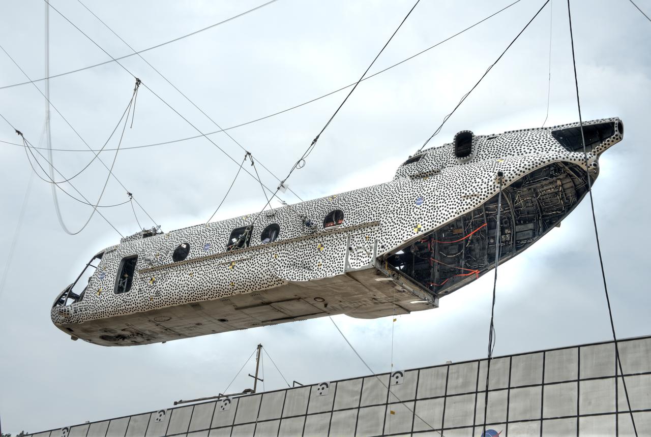
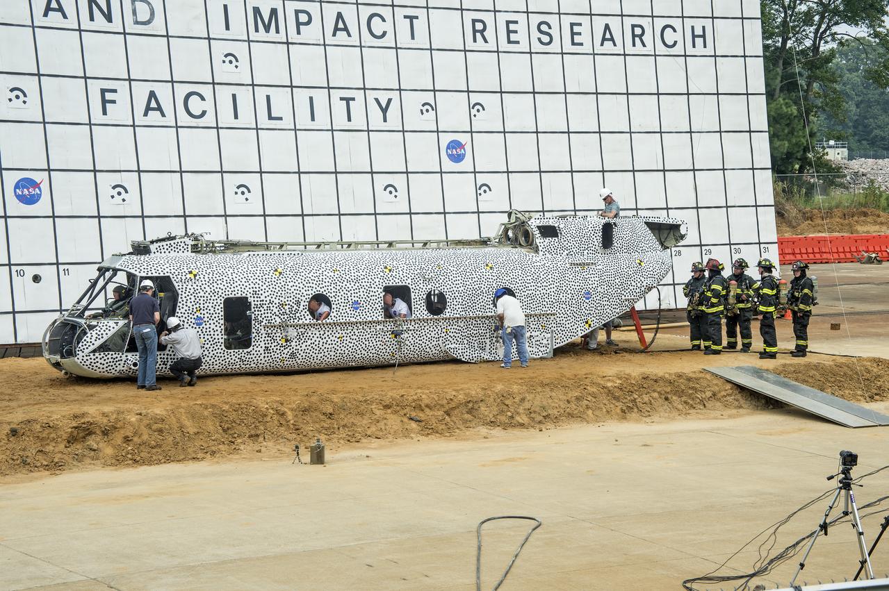
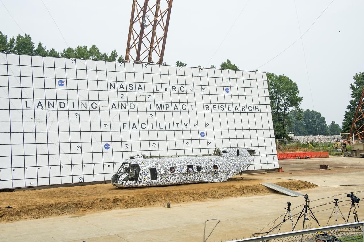
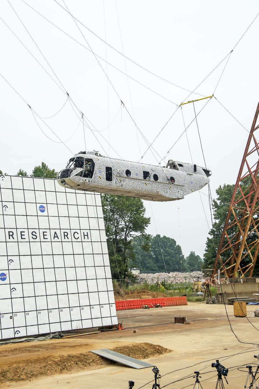
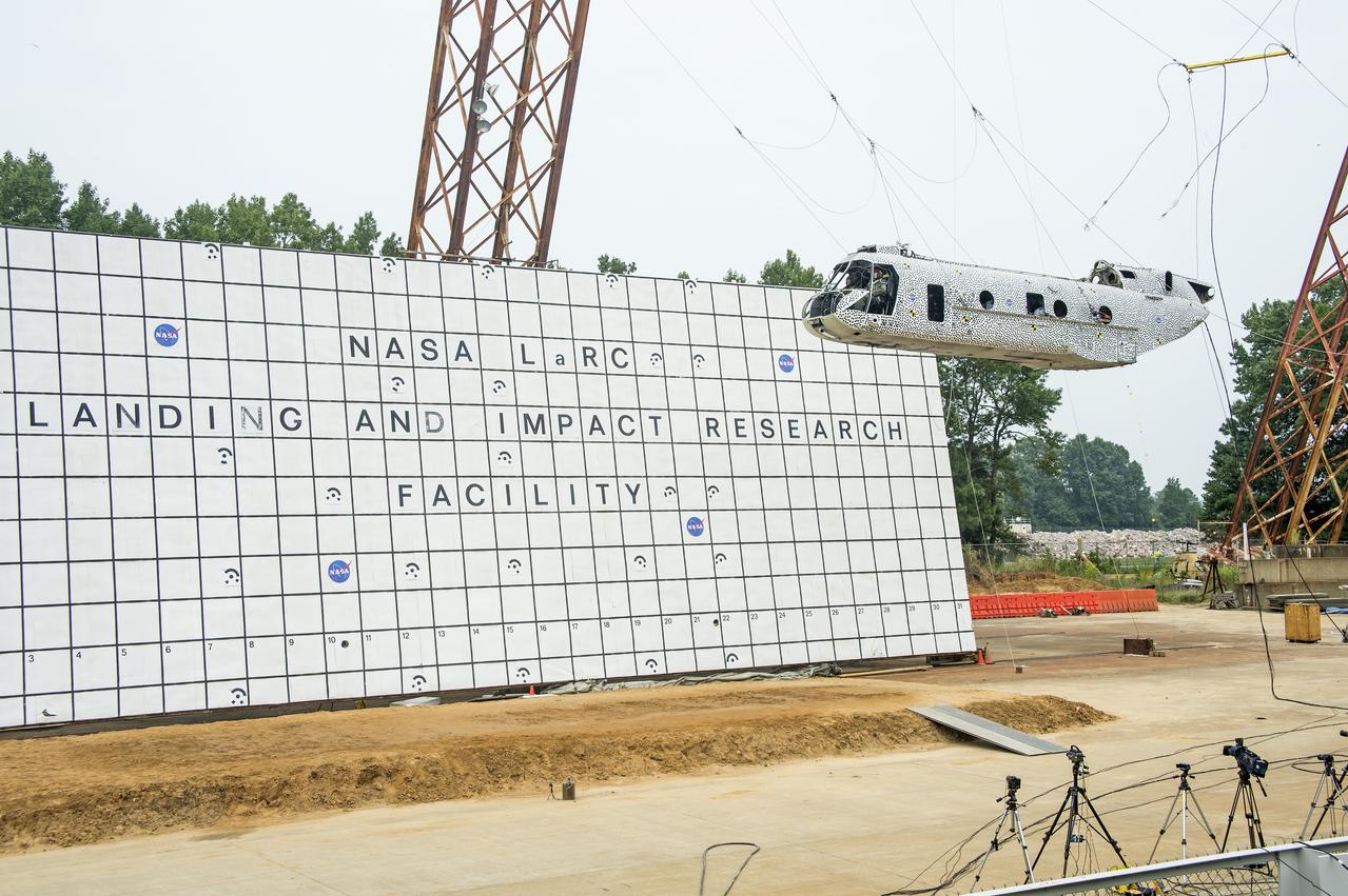
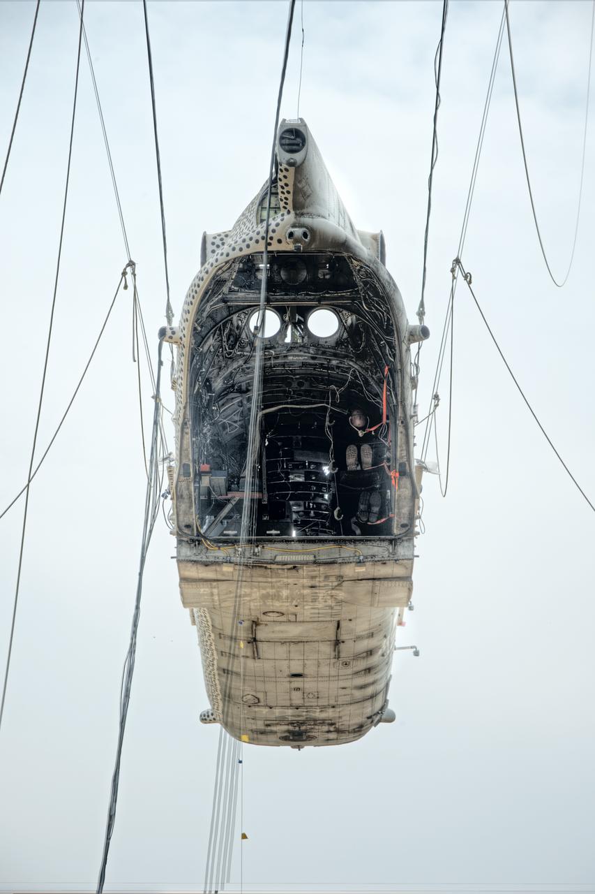
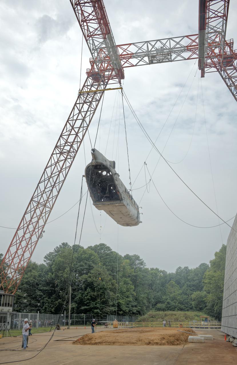
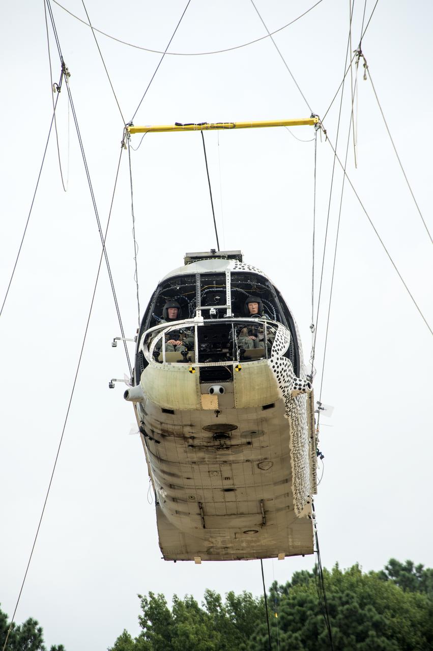
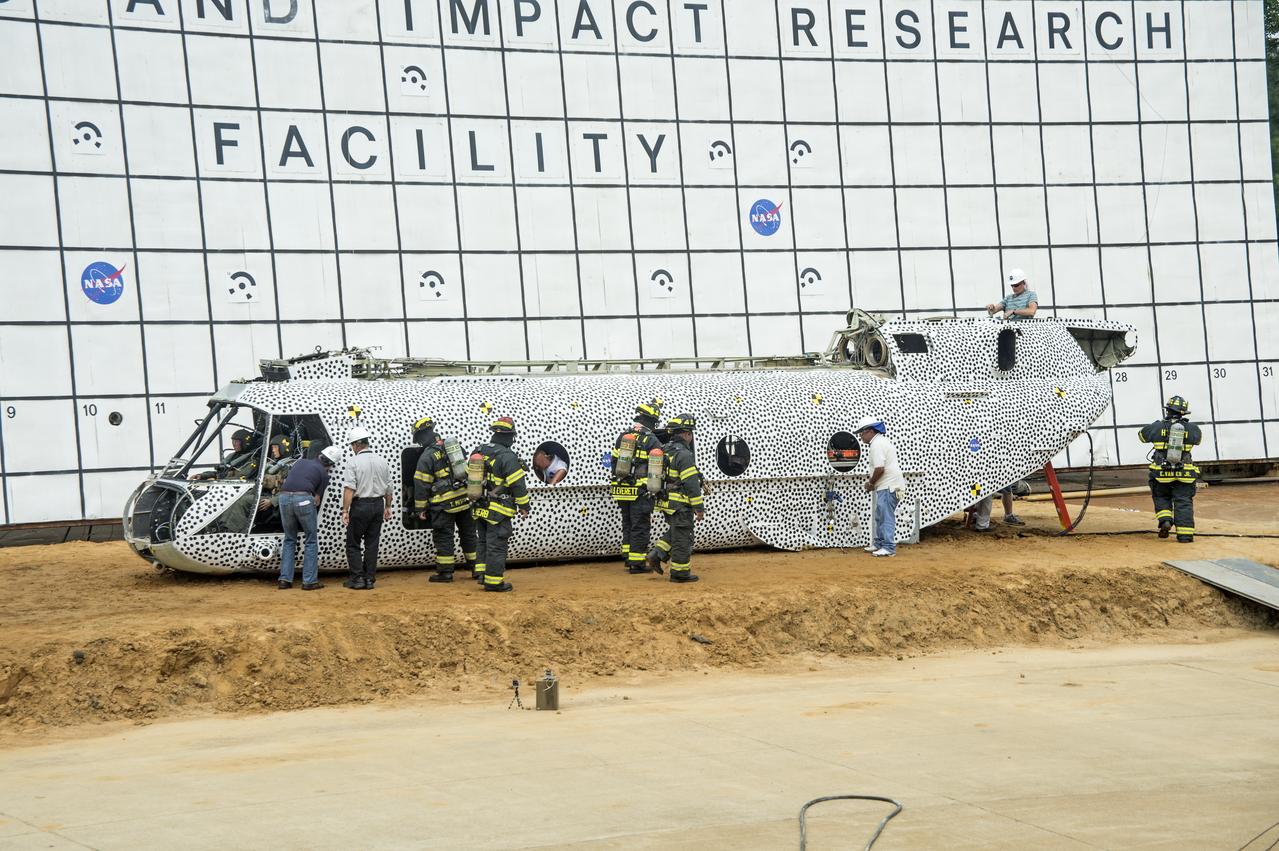
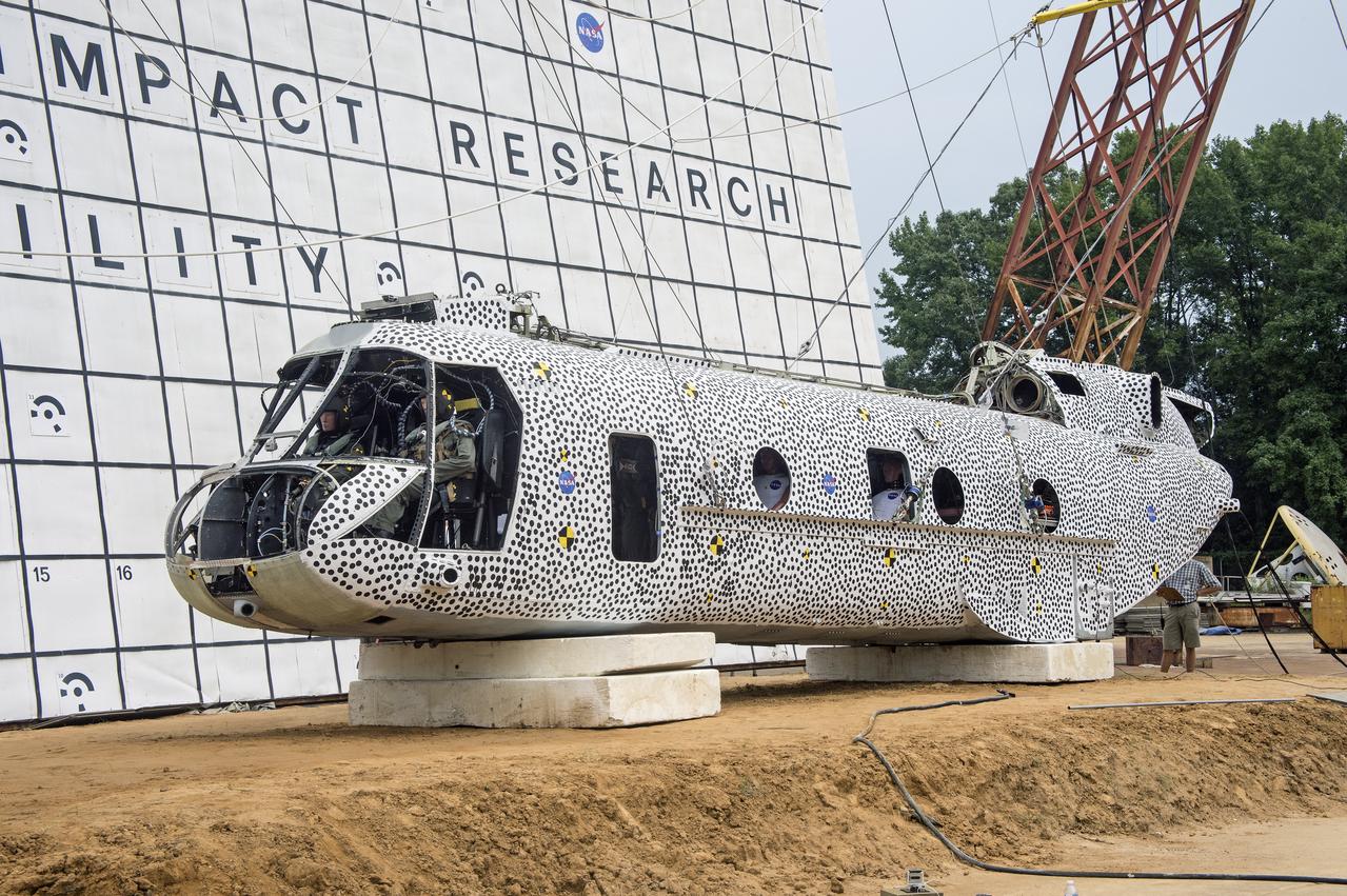
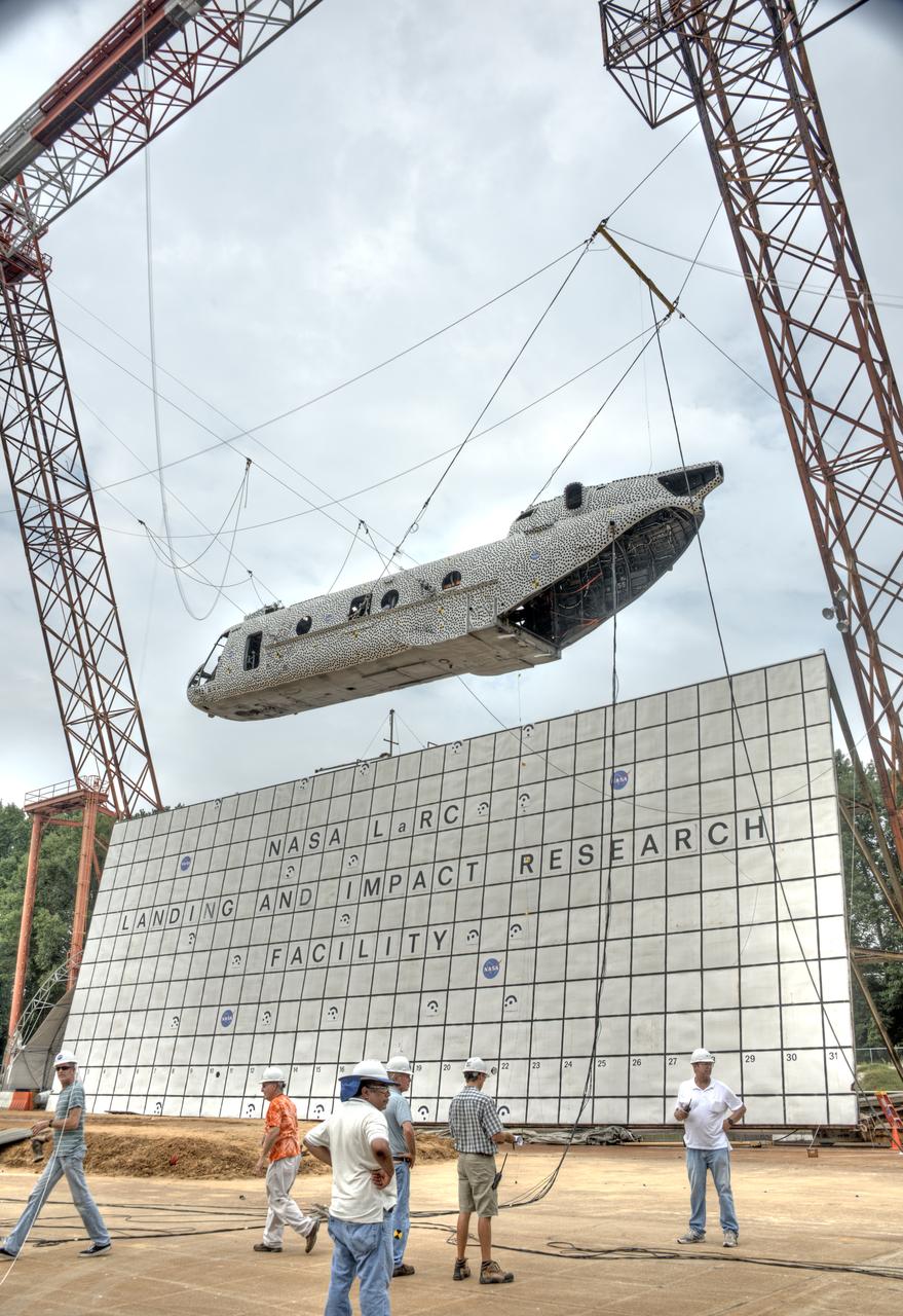
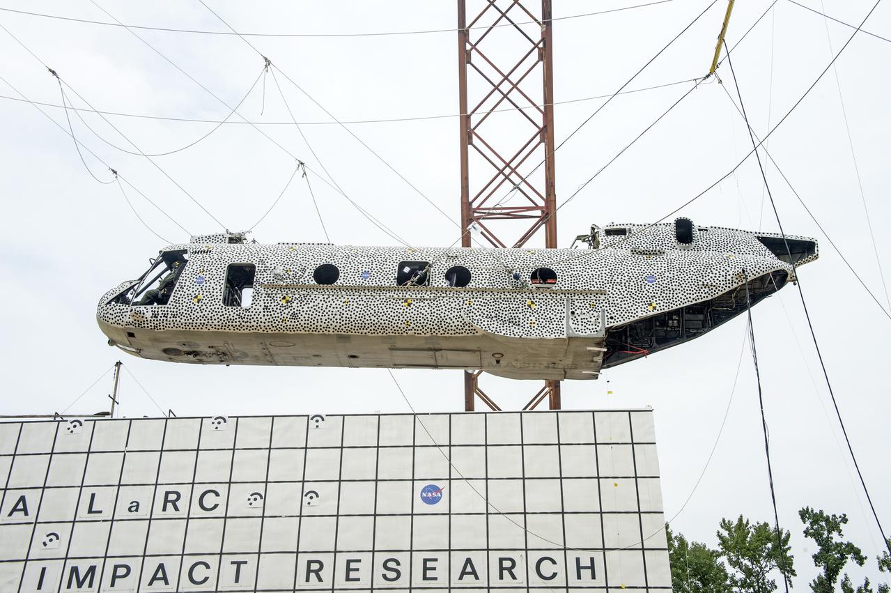
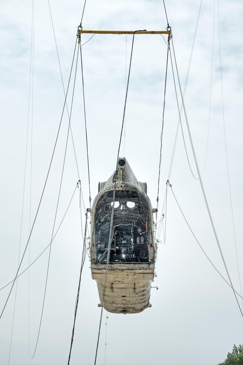
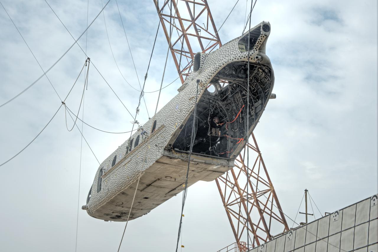
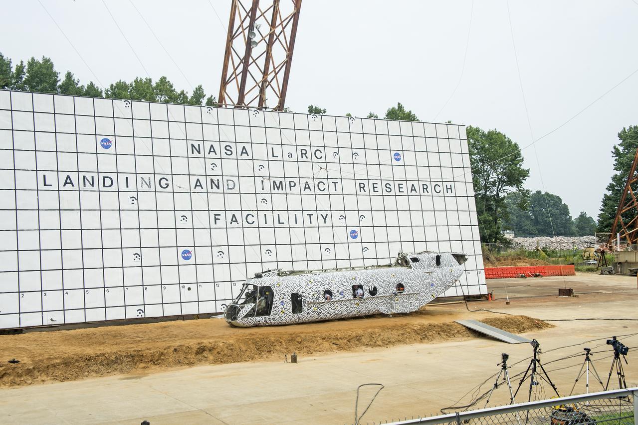
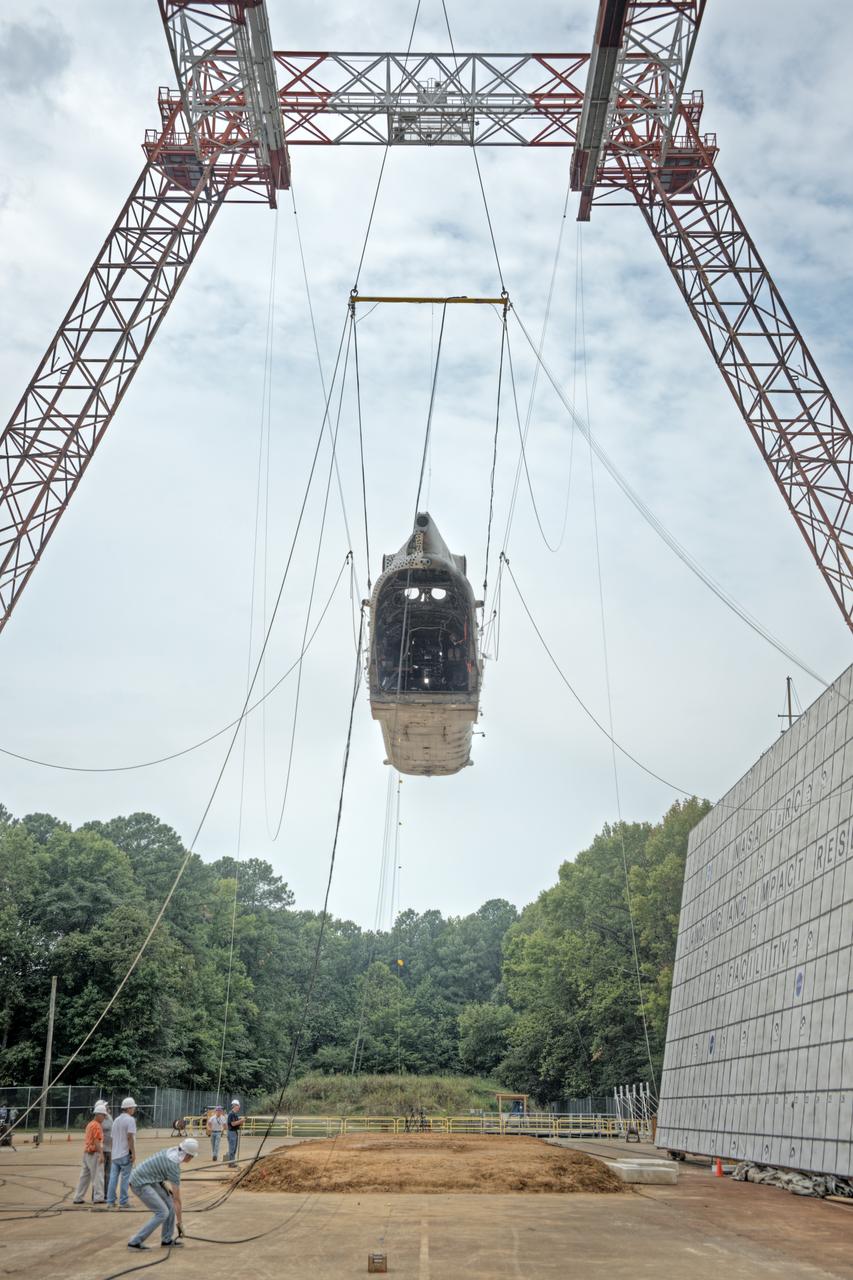
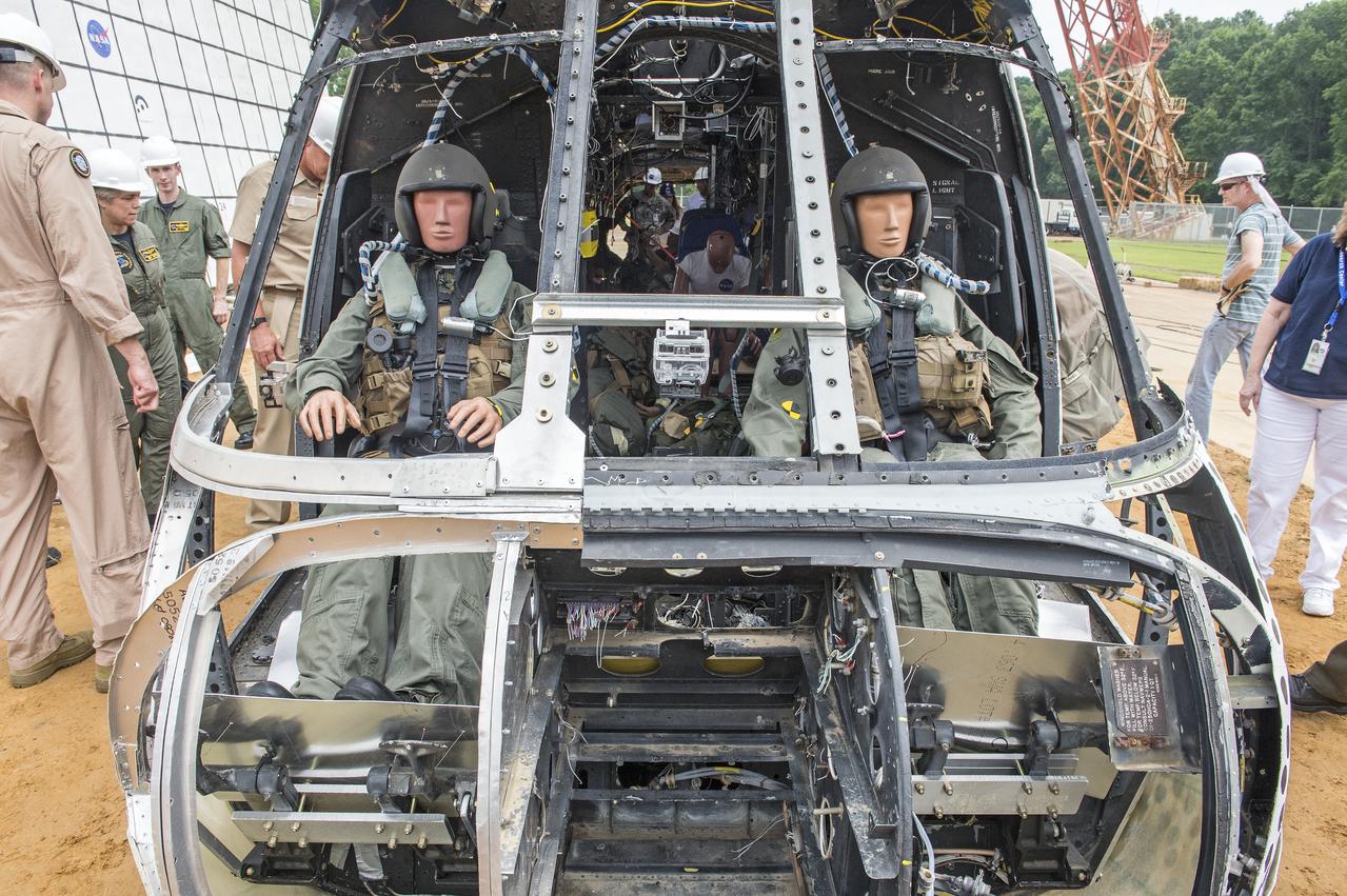
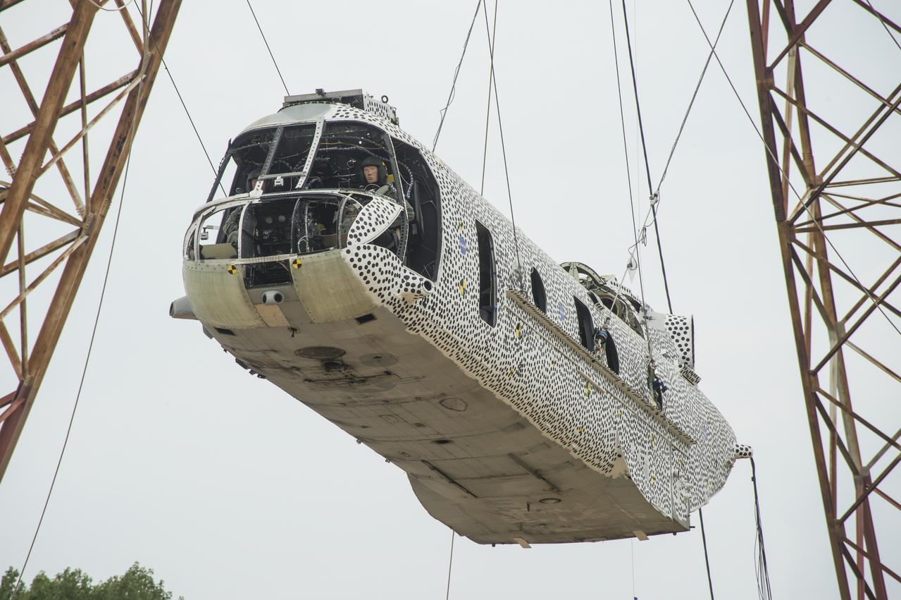
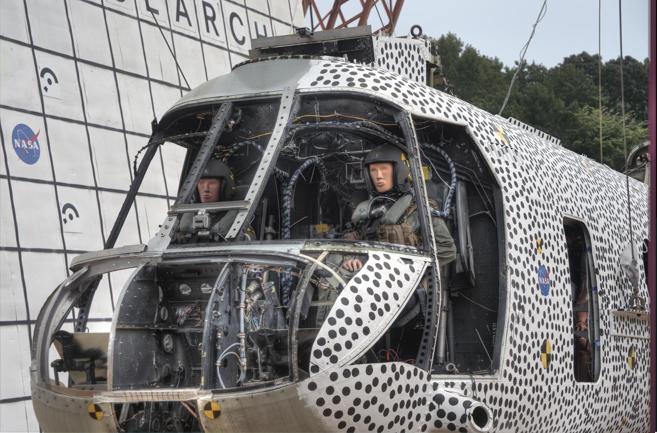
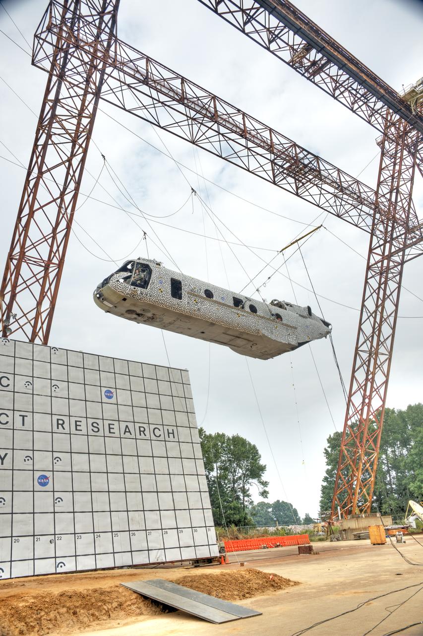
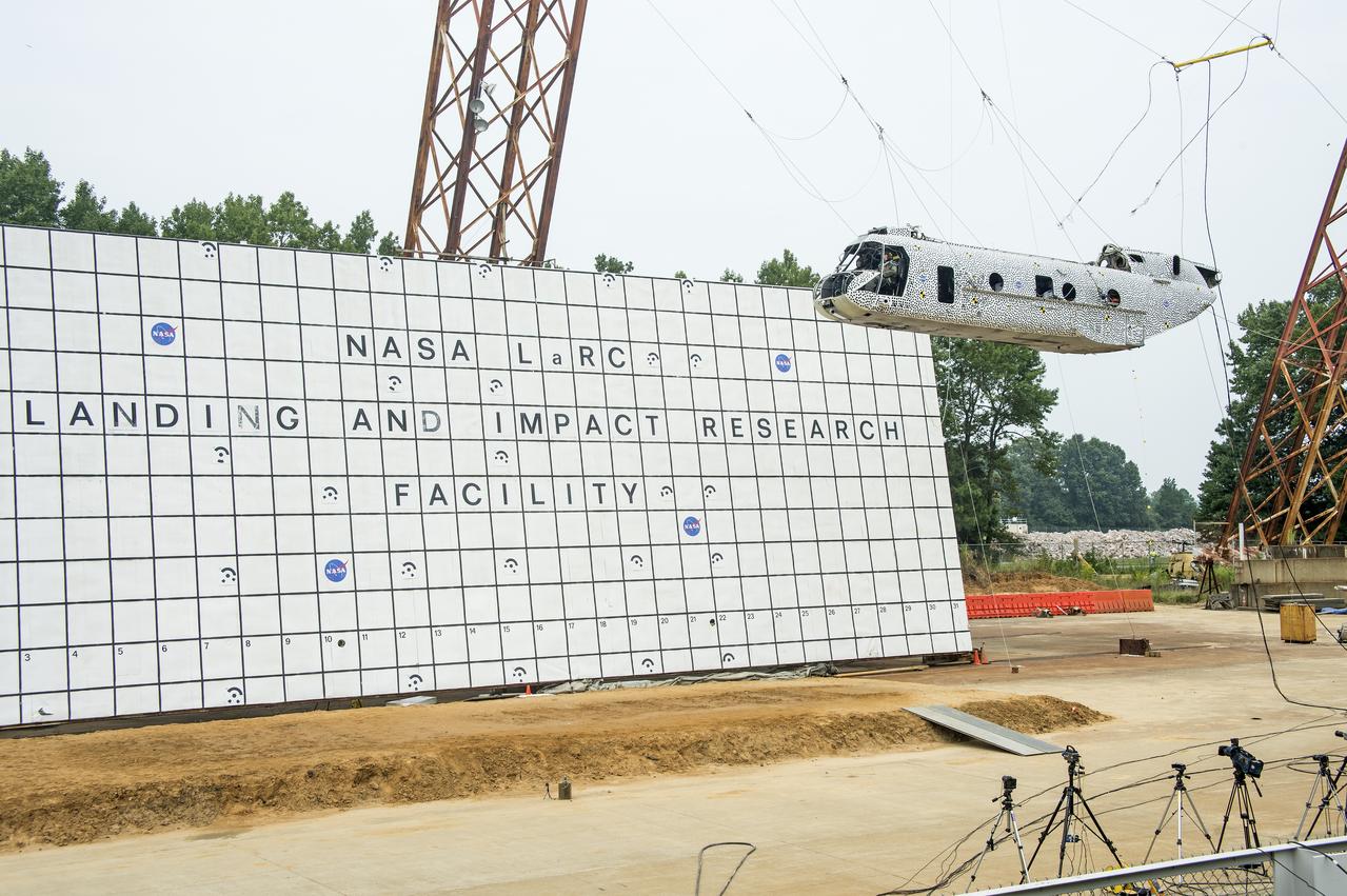
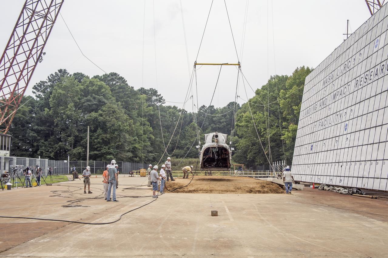
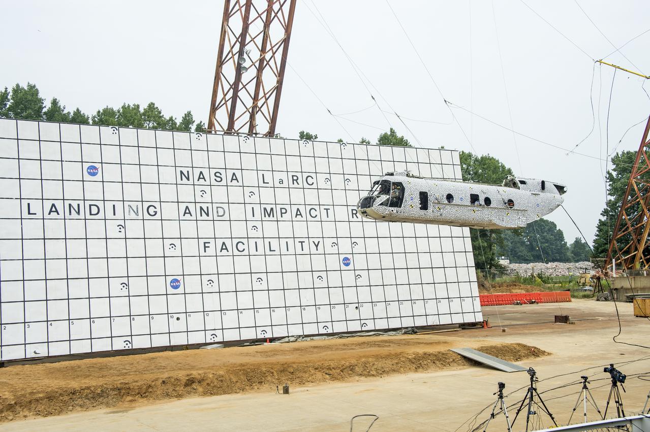
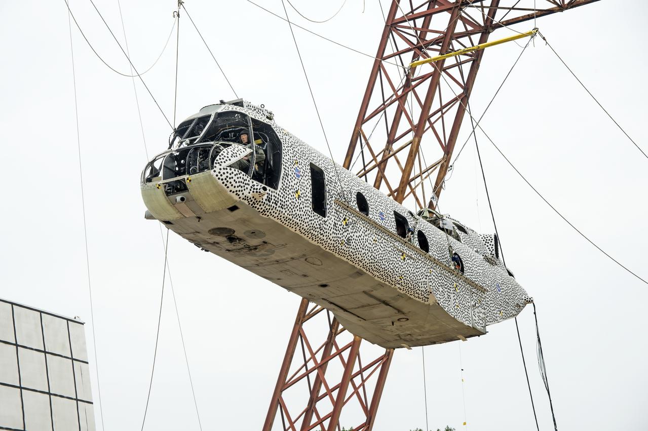
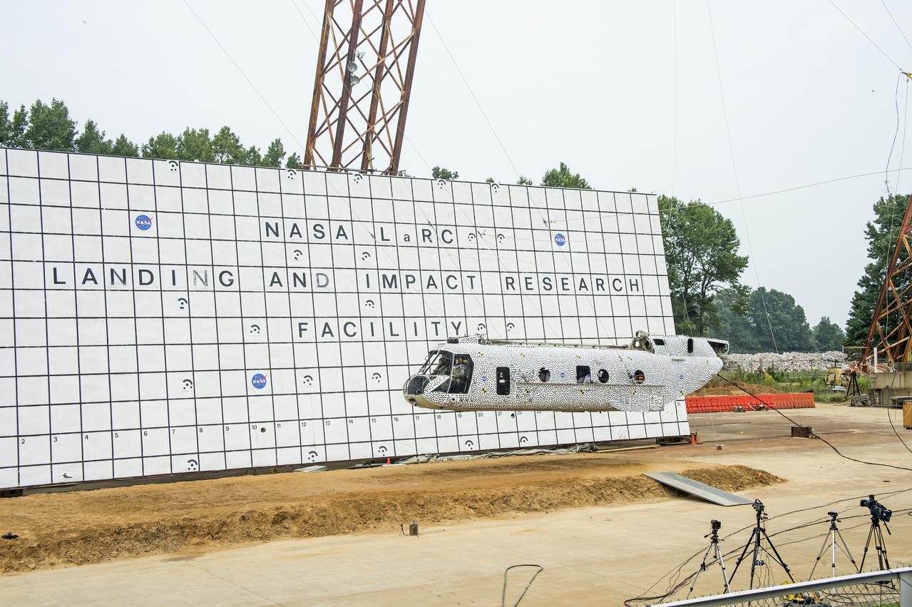
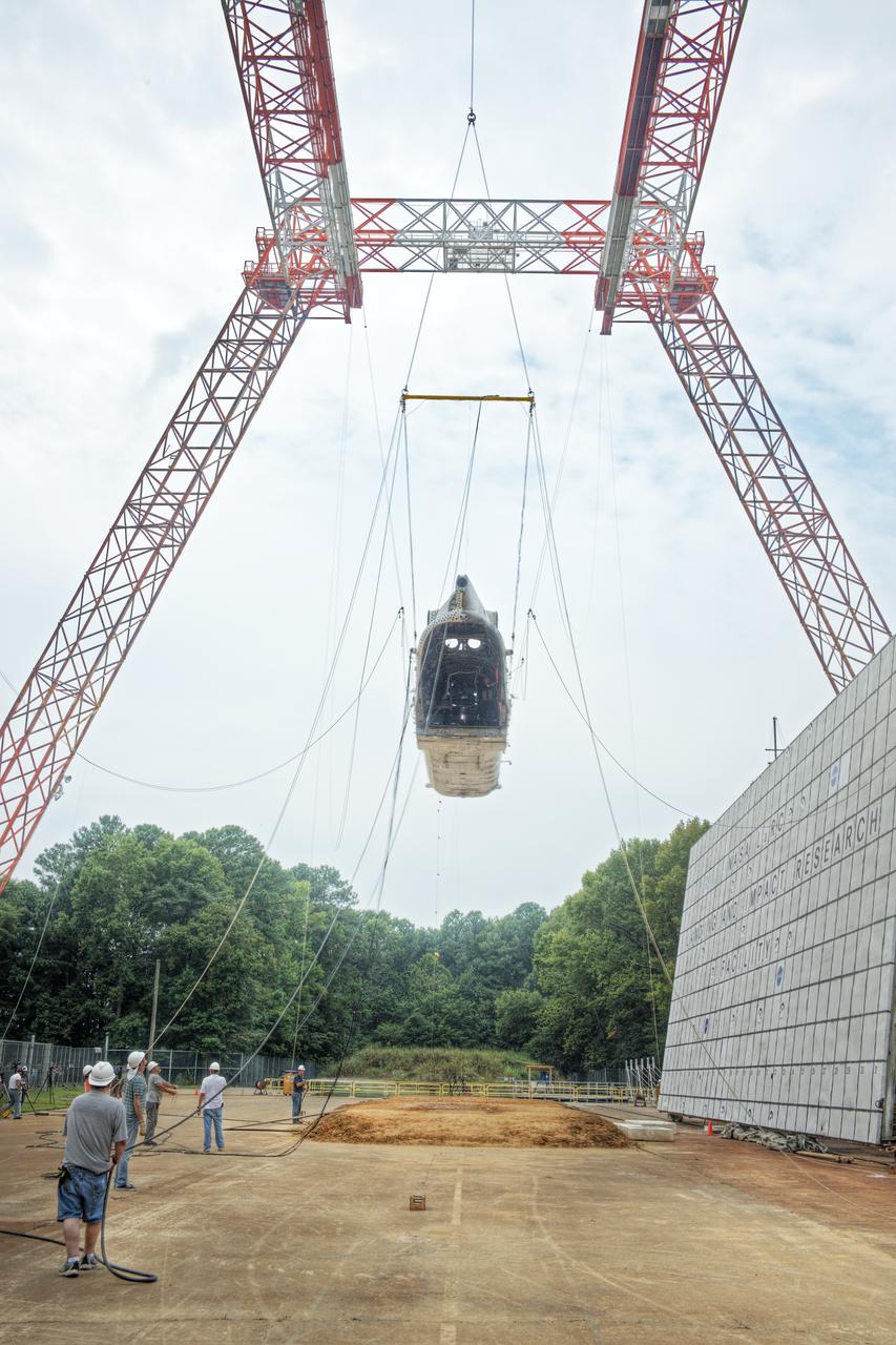
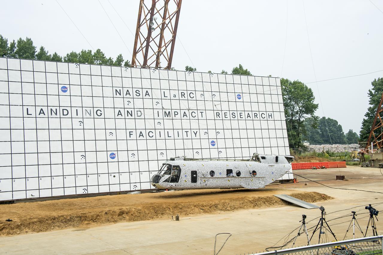
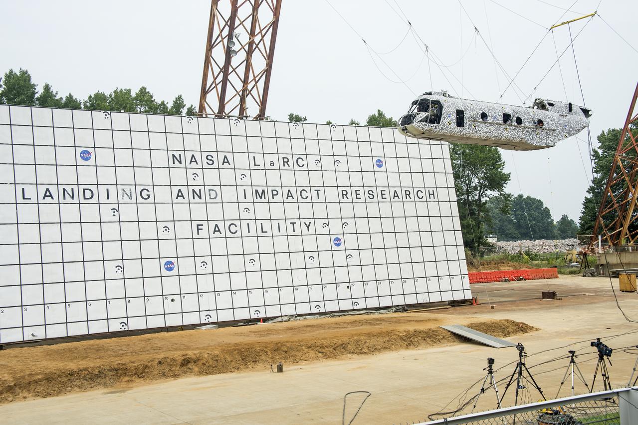
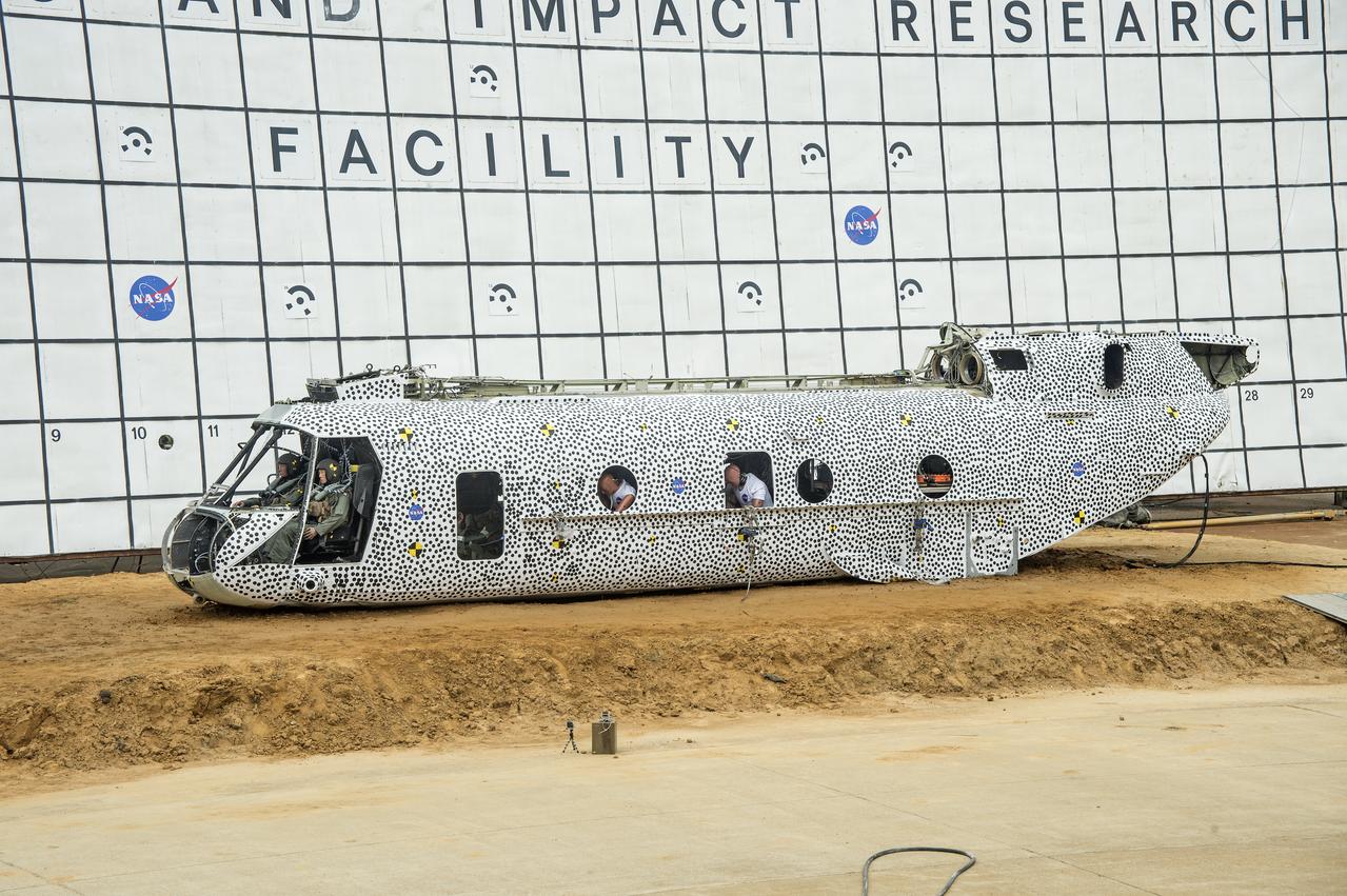
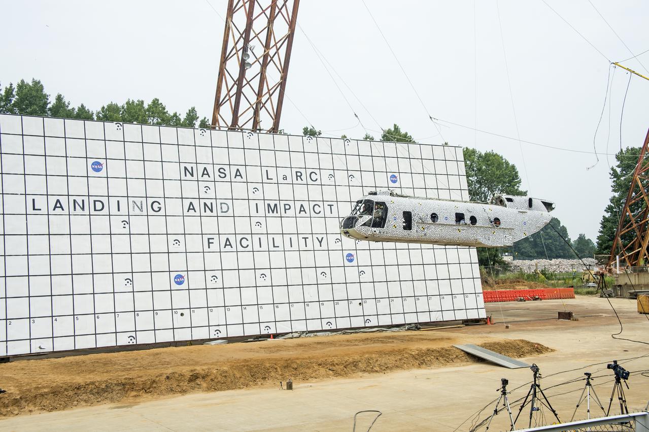
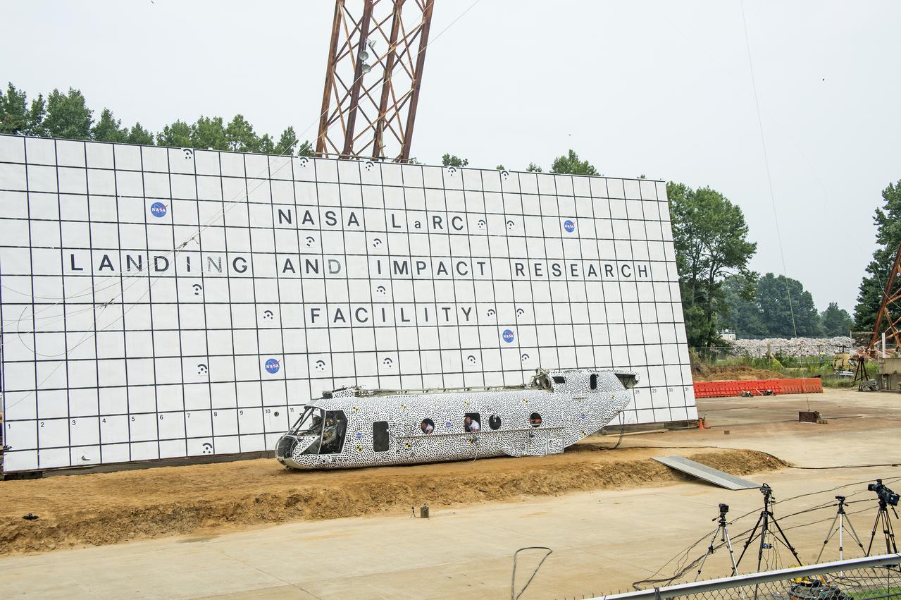
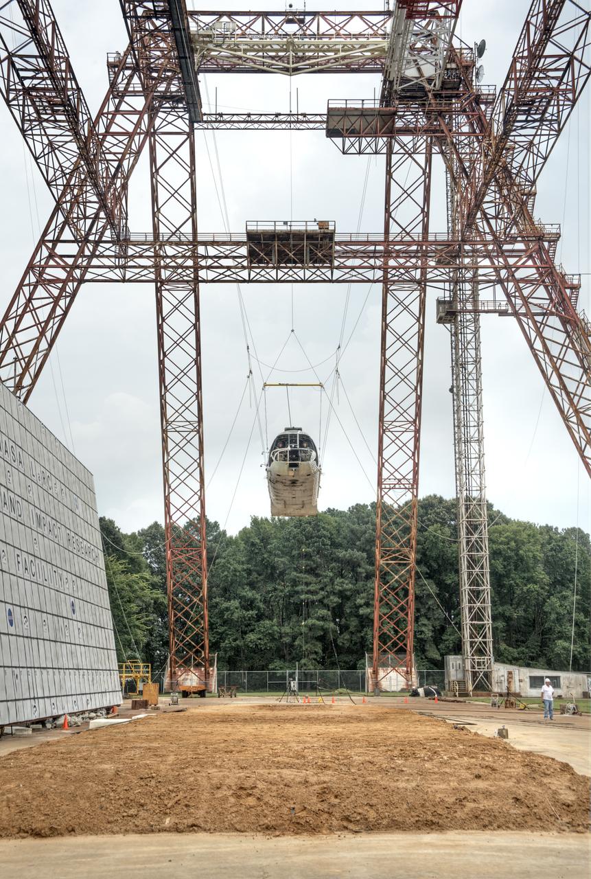
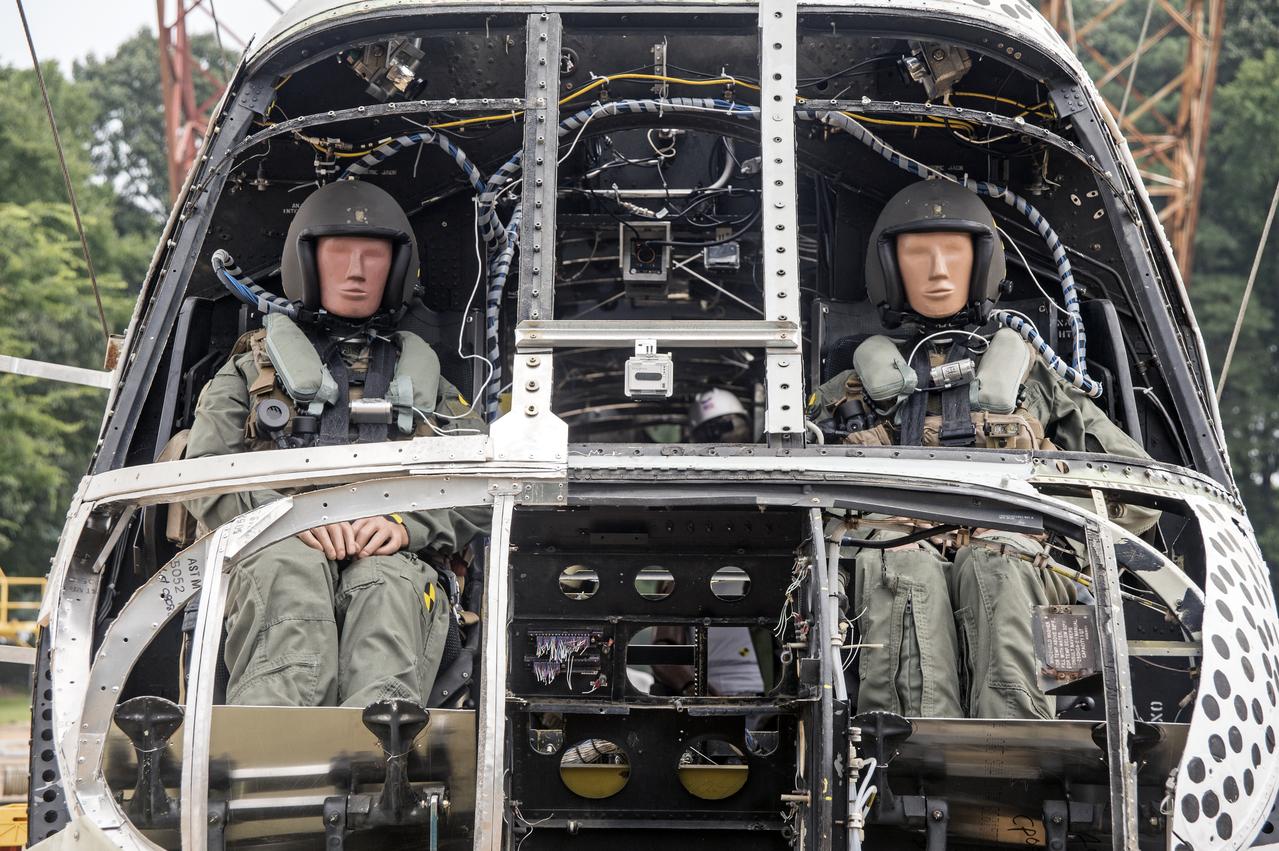
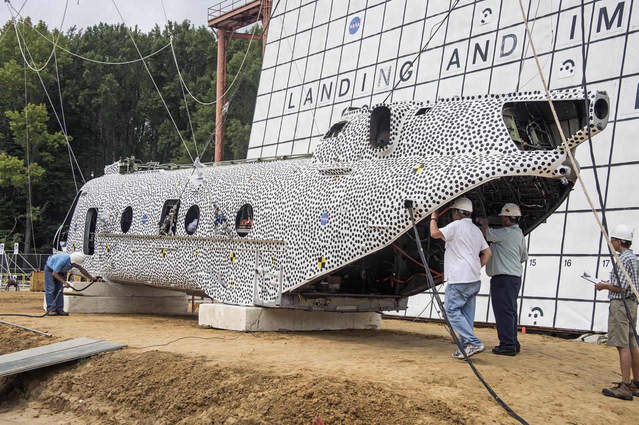
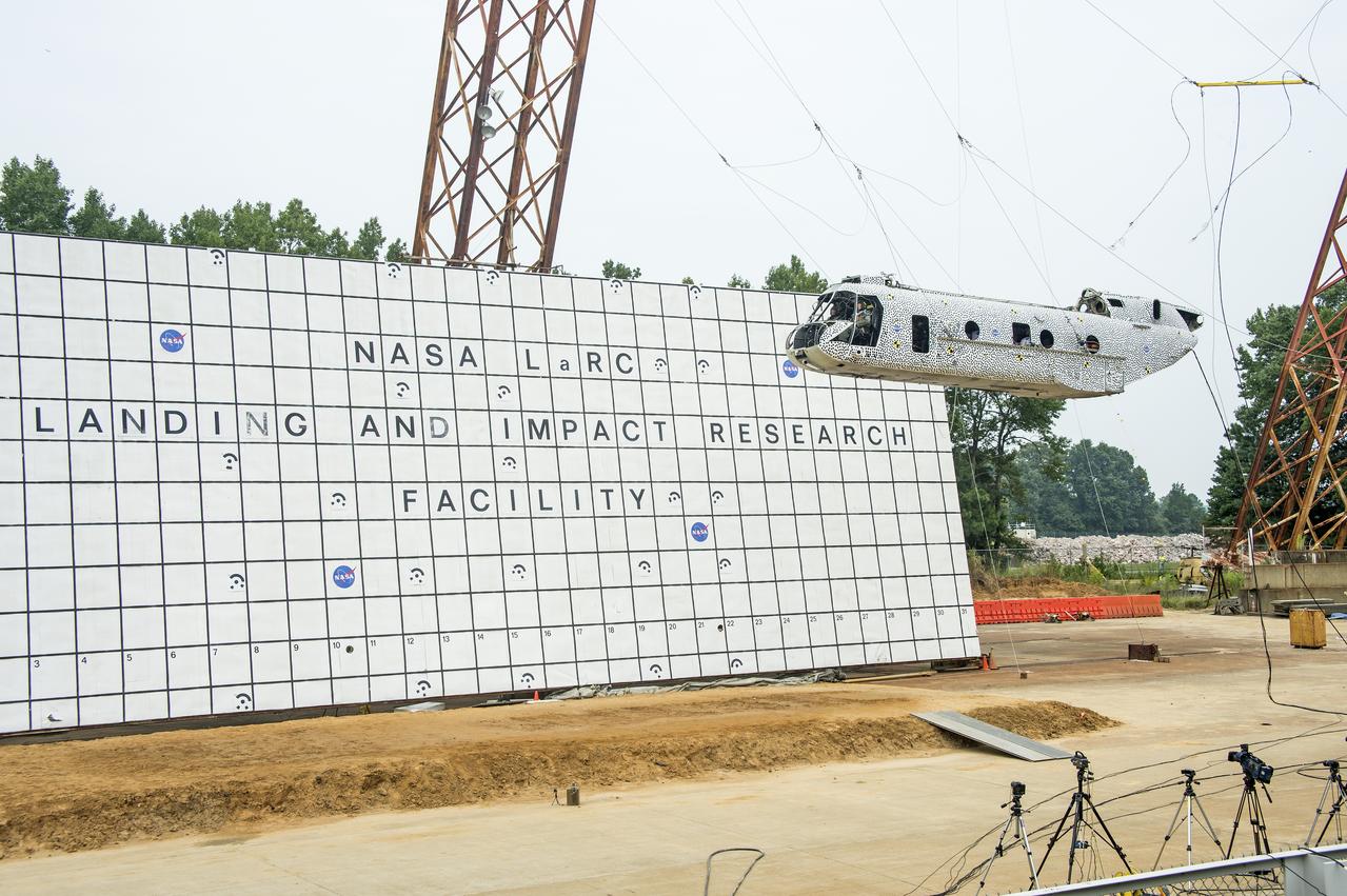
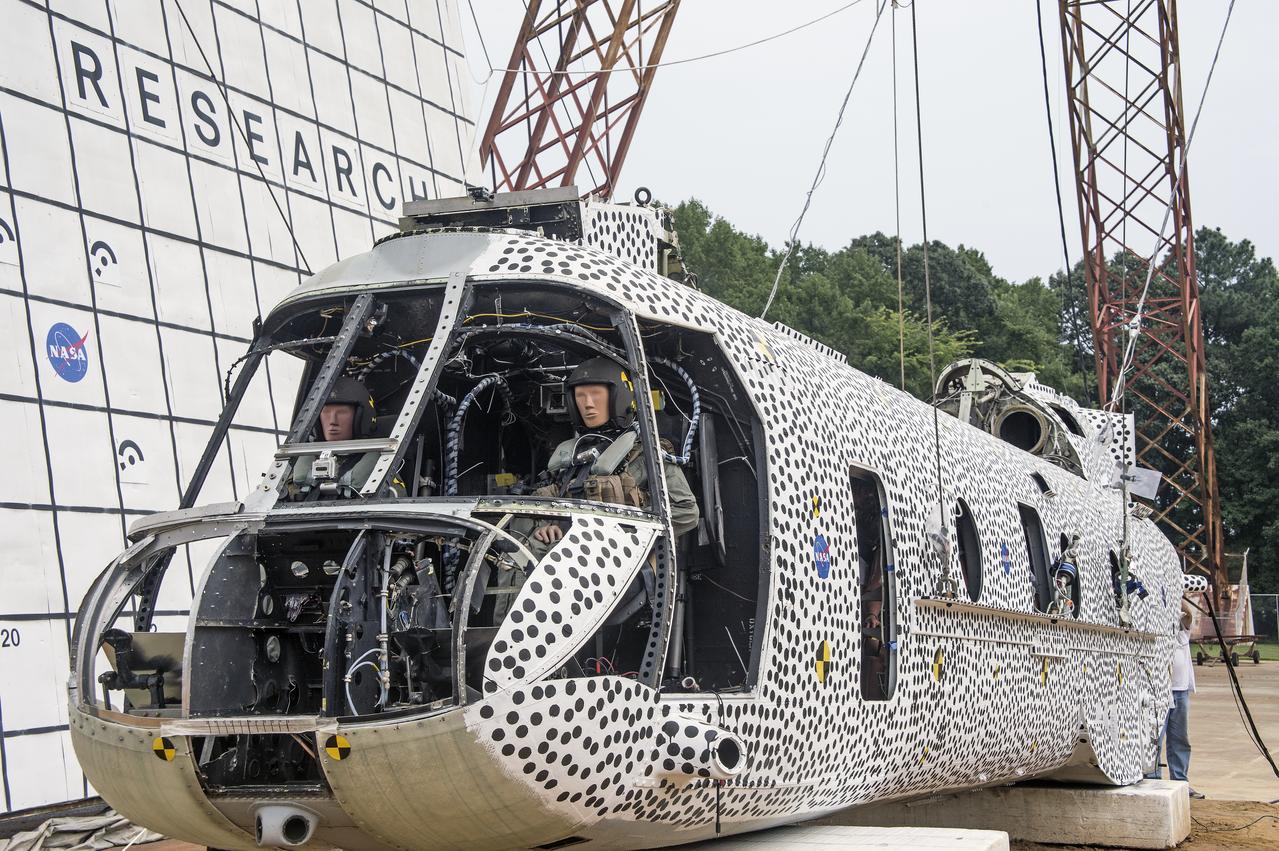
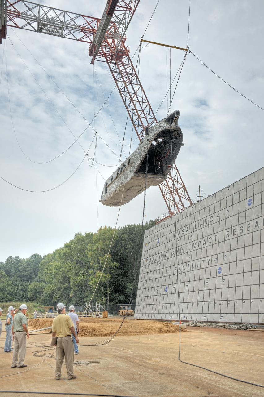
(TRACT) Transport Rotorcraft Aircraft Testbed: Helicopter airframe drop test at NASA Langley's Landing and Impact Research Facility (LandIR)
(TRACT) Transport Rotorcraft Aircraft Testbed: Helicopter airframe drop test at NASA Langley's Landing and Impact Research Facility (LandIR)
(TRACT) Transport Rotorcraft Aircraft Testbed: Helicopter airframe drop test at NASA Langley's Landing and Impact Research Facility (LandIR)
(TRACT) Transport Rotorcraft Aircraft Testbed: Helicopter airframe drop test at NASA Langley's Landing and Impact Research Facility (LandIR)
(TRACT) Transport Rotorcraft Aircraft Testbed: Helicopter airframe drop test at NASA Langley's Landing and Impact Research Facility (LandIR)
(TRACT) Transport Rotorcraft Aircraft Testbed: Helicopter airframe drop test at NASA Langley's Landing and Impact Research Facility (LandIR)
(TRACT) Transport Rotorcraft Aircraft Testbed: Helicopter airframe drop test at NASA Langley's Landing and Impact Research Facility (LandIR)
(TRACT) Transport Rotorcraft Aircraft Testbed: Helicopter airframe drop test at NASA Langley's Landing and Impact Research Facility (LandIR)
(TRACT) Transport Rotorcraft Aircraft Testbed: Helicopter airframe drop test at NASA Langley's Landing and Impact Research Facility (LandIR)
(TRACT) Transport Rotorcraft Aircraft Testbed: Helicopter airframe drop test at NASA Langley's Landing and Impact Research Facility (LandIR)
(TRACT) Transport Rotorcraft Aircraft Testbed: Helicopter airframe drop test at NASA Langley's Landing and Impact Research Facility (LandIR)
(TRACT) Transport Rotorcraft Aircraft Testbed: Helicopter airframe drop test at NASA Langley's Landing and Impact Research Facility (LandIR)
(TRACT) Transport Rotorcraft Aircraft Testbed: Helicopter airframe drop test at NASA Langley's Landing and Impact Research Facility (LandIR)
(TRACT) Transport Rotorcraft Aircraft Testbed: Helicopter airframe drop test at NASA Langley's Landing and Impact Research Facility (LandIR)
(TRACT) Transport Rotorcraft Aircraft Testbed: Helicopter airframe drop test at NASA Langley's Landing and Impact Research Facility (LandIR)
(TRACT) Transport Rotorcraft Aircraft Testbed: Helicopter airframe drop test at NASA Langley's Landing and Impact Research Facility (LandIR)
(TRACT) Transport Rotorcraft Aircraft Testbed: Helicopter airframe drop test at NASA Langley's Landing and Impact Research Facility (LandIR)
(TRACT) Transport Rotorcraft Aircraft Testbed: Helicopter airframe drop test at NASA Langley's Landing and Impact Research Facility (LandIR)
(TRACT) Transport Rotorcraft Aircraft Testbed: Helicopter airframe drop test at NASA Langley's Landing and Impact Research Facility (LandIR)
(TRACT) Transport Rotorcraft Aircraft Testbed: Helicopter airframe drop test at NASA Langley's Landing and Impact Research Facility (LandIR)
(TRACT) Transport Rotorcraft Aircraft Testbed: Helicopter airframe drop test at NASA Langley's Landing and Impact Research Facility (LandIR)
(TRACT) Transport Rotorcraft Aircraft Testbed: Helicopter airframe drop test at NASA Langley's Landing and Impact Research Facility (LandIR)
(TRACT) Transport Rotorcraft Aircraft Testbed: Helicopter airframe drop test at NASA Langley's Landing and Impact Research Facility (LandIR)
(TRACT) Transport Rotorcraft Aircraft Testbed: Helicopter airframe drop test at NASA Langley's Landing and Impact Research Facility (LandIR)
(TRACT) Transport Rotorcraft Aircraft Testbed: Helicopter airframe drop test at NASA Langley's Landing and Impact Research Facility (LandIR)
(TRACT) Transport Rotorcraft Aircraft Testbed: Helicopter airframe drop test at NASA Langley's Landing and Impact Research Facility (LandIR)
(TRACT) Transport Rotorcraft Aircraft Testbed: Helicopter airframe drop test at NASA Langley's Landing and Impact Research Facility (LandIR)
(TRACT) Transport Rotorcraft Aircraft Testbed: Helicopter airframe drop test at NASA Langley's Landing and Impact Research Facility (LandIR)
(TRACT) Transport Rotorcraft Aircraft Testbed: Helicopter airframe drop test at NASA Langley's Landing and Impact Research Facility (LandIR)
(TRACT) Transport Rotorcraft Aircraft Testbed: Helicopter airframe drop test at NASA Langley's Landing and Impact Research Facility (LandIR)

(TRACT) Transport Rotorcraft Aircraft Testbed: Helicopter airframe drop test at NASA Langley's Landing and Impact Research Facility (LandIR)
(TRACT) Transport Rotorcraft Aircraft Testbed: Helicopter airframe drop test at NASA Langley's Landing and Impact Research Facility (LandIR)
(TRACT) Transport Rotorcraft Aircraft Testbed: Helicopter airframe drop test at NASA Langley's Landing and Impact Research Facility (LandIR)
(TRACT) Transport Rotorcraft Aircraft Testbed: Helicopter airframe drop test at NASA Langley's Landing and Impact Research Facility (LandIR)
(TRACT) Transport Rotorcraft Aircraft Testbed: Helicopter airframe drop test at NASA Langley's Landing and Impact Research Facility (LandIR)
(TRACT) Transport Rotorcraft Aircraft Testbed: Helicopter airframe drop test at NASA Langley's Landing and Impact Research Facility (LandIR)
(TRACT) Transport Rotorcraft Aircraft Testbed: Helicopter airframe drop test at NASA Langley's Landing and Impact Research Facility (LandIR)
(TRACT) Transport Rotorcraft Aircraft Testbed: Helicopter airframe drop test at NASA Langley's Landing and Impact Research Facility (LandIR)

(TRACT) Transport Rotorcraft Aircraft Testbed: Helicopter airframe drop test at NASA Langley's Landing and Impact Research Facility (LandIR)
(TRACT) Transport Rotorcraft Aircraft Testbed: Helicopter airframe drop test at NASA Langley's Landing and Impact Research Facility (LandIR)
(TRACT) Transport Rotorcraft Aircraft Testbed: Helicopter airframe drop test at NASA Langley's Landing and Impact Research Facility (LandIR)
(TRACT) Transport Rotorcraft Aircraft Testbed: Helicopter airframe drop test at NASA Langley's Landing and Impact Research Facility (LandIR)
(TRACT) Transport Rotorcraft Aircraft Testbed: Helicopter airframe drop test at NASA Langley's Landing and Impact Research Facility (LandIR)
(TRACT) Transport Rotorcraft Aircraft Testbed: Helicopter airframe drop test at NASA Langley's Landing and Impact Research Facility (LandIR)
(TRACT) Transport Rotorcraft Aircraft Testbed: Helicopter airframe drop test at NASA Langley's Landing and Impact Research Facility (LandIR)
(TRACT) Transport Rotorcraft Aircraft Testbed: Helicopter airframe drop test at NASA Langley's Landing and Impact Research Facility (LandIR)
(TRACT) Transport Rotorcraft Aircraft Testbed: Helicopter airframe drop test at NASA Langley's Landing and Impact Research Facility (LandIR)
(TRACT) Transport Rotorcraft Aircraft Testbed: Helicopter airframe drop test at NASA Langley's Landing and Impact Research Facility (LandIR)
(TRACT) Transport Rotorcraft Aircraft Testbed: Helicopter airframe drop test at NASA Langley's Landing and Impact Research Facility (LandIR)
(TRACT) Transport Rotorcraft Aircraft Testbed: Helicopter airframe drop test at NASA Langley's Landing and Impact Research Facility (LandIR)
(TRACT) Transport Rotorcraft Aircraft Testbed: Helicopter airframe drop test at NASA Langley's Landing and Impact Research Facility (LandIR)

(TRACT) Transport Rotorcraft Aircraft Testbed: Helicopter airframe drop test at NASA Langley's Landing and Impact Research Facility (LandIR)
(TRACT) Transport Rotorcraft Aircraft Testbed: Helicopter airframe drop test at NASA Langley's Landing and Impact Research Facility (LandIR)
(TRACT) Transport Rotorcraft Aircraft Testbed: Helicopter airframe drop test at NASA Langley's Landing and Impact Research Facility (LandIR)
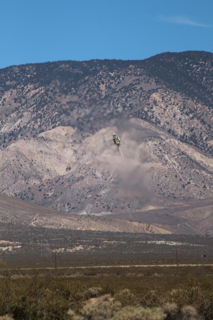
This image was taken during a flight test of JPL Autonomous Descent and Ascent Powered-Flight Testbed ADAPT. The testbed was flown aboard a Masten Space System Xombie rocket.-Flight Testbed ADAPT.
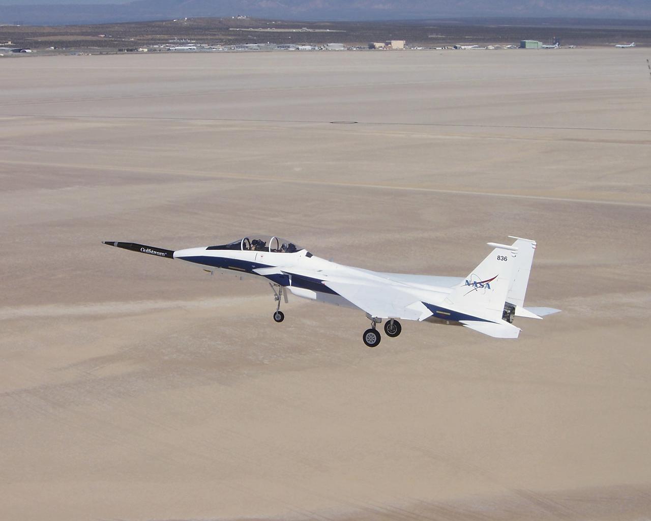
Approaching the runway after the first evaluation flight of the Quiet Spike project, NASA's F-15B testbed aircraft cruises over Roger's Dry Lakebed near the Dryden Flight Research Center. The Quiet Spike was developed by Gulfstream Aerospace as a means of controlling and reducing the sonic boom caused by an aircraft 'breaking' the sound barrier.
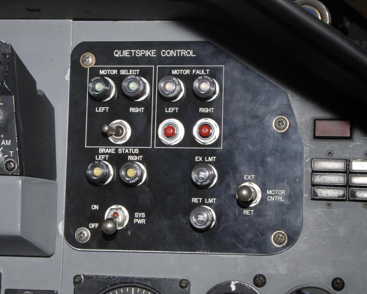
The control panel for the joint NASA/Gulfstream Quiet Spike project, located in the backseat of NASA's F-15B testbed aircraft. The project seeks to verify the structural integrity of the multi-segmented, articulating spike attachment designed to reduce and control a sonic boom.
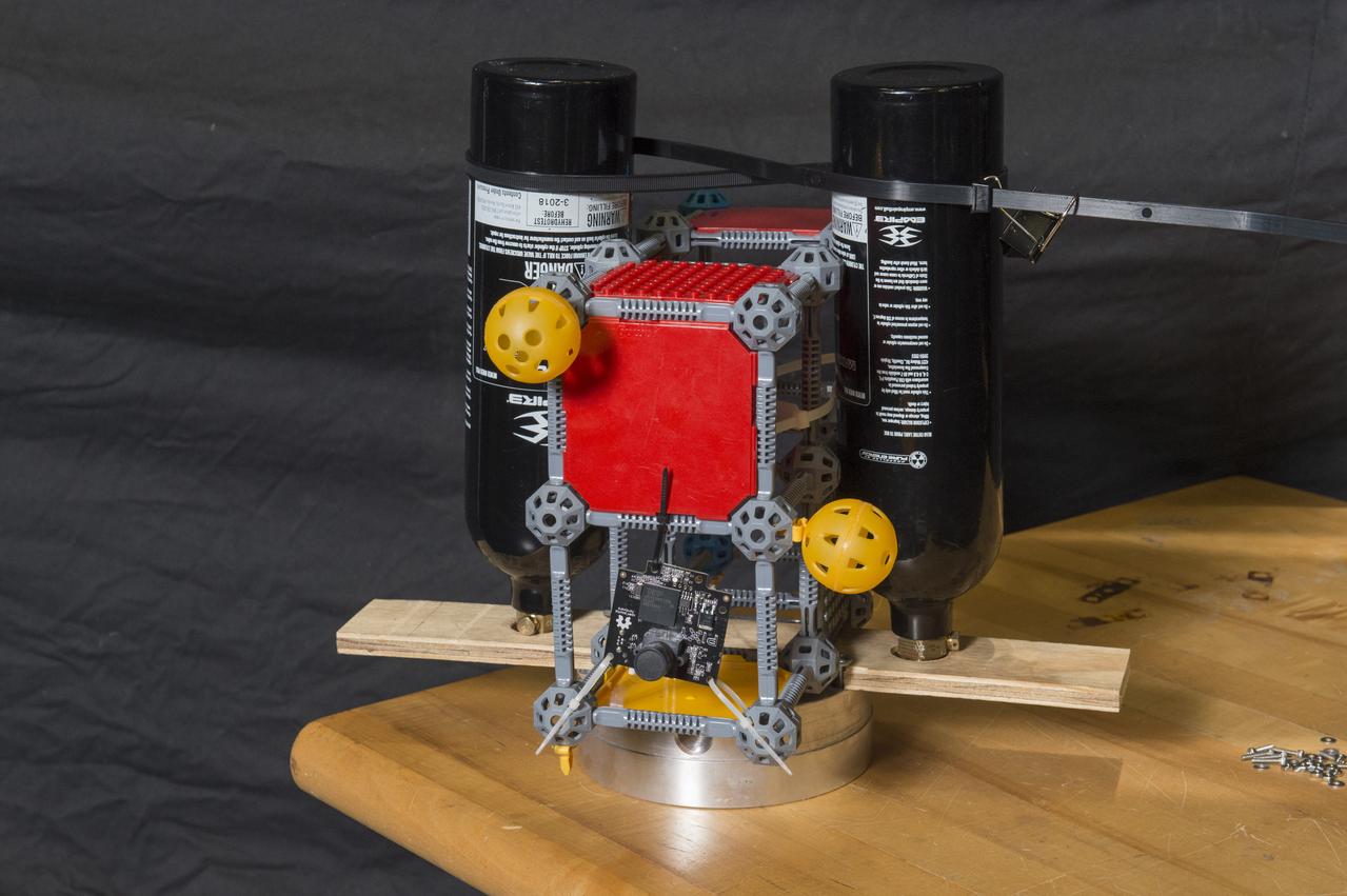
First Generation Agile Engineering Prototype of Electric Sail 6U CubeSat Testbed Article
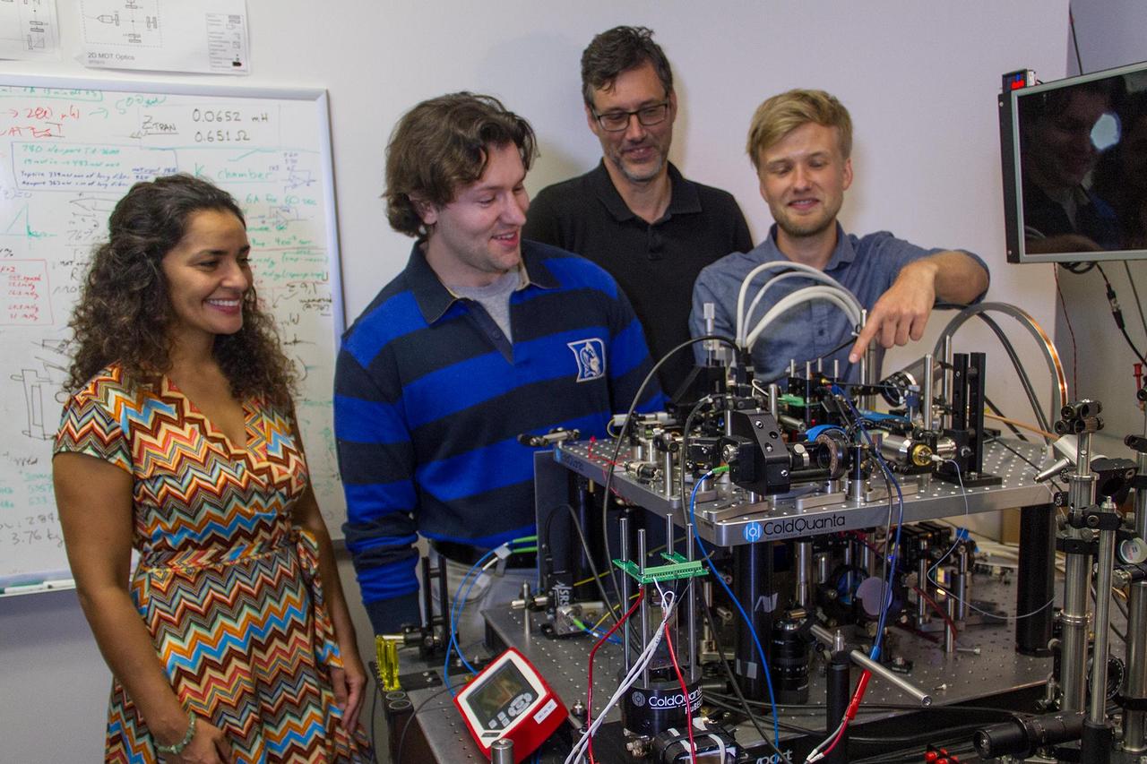
Members of the Cold Atom Laboratory team at NASA Jet Propulsion Laboratory are seen here with their ground-based testbed, which can reliably create a Bose-Einstein condensate.
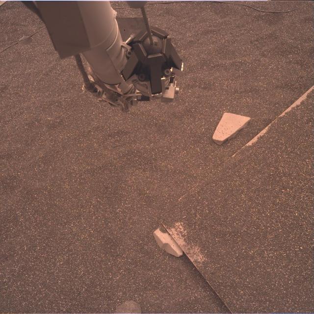
This test image from an engineering model of NASA's InSight lander shows part of the lander's robotic arm and the simulated Martian ground at a testbed at NASA's Jet Propulsion Laboratory in Pasadena, California. The testbed aims to mimic the environment InSight will encounter at Mars so engineers can prepare for the spacecraft operations to come. This image is expected to be similar to the raw or unprocessed images that InSight will send back to Earth. It was taken by the instrument deployment camera attached to InSight's robotic arm. https://photojournal.jpl.nasa.gov/catalog/PIA22827

NASA’s C-20A with Generation Orbit’s hypersonic testbed attached is chased by the agency’s F-18 jet for safety and photography.
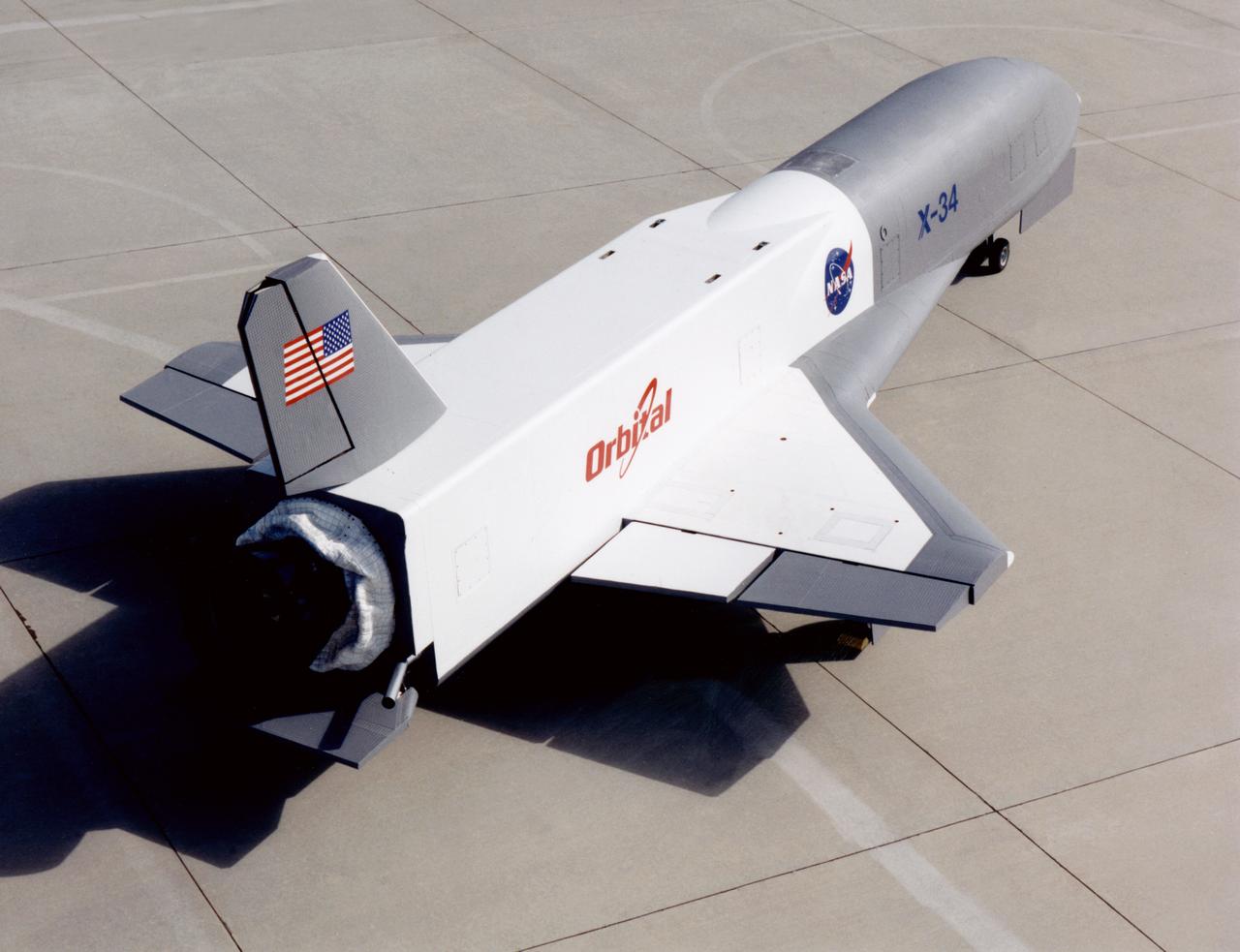
X-34 Technology Testbed Demonstrator on NASA Dryden ramp
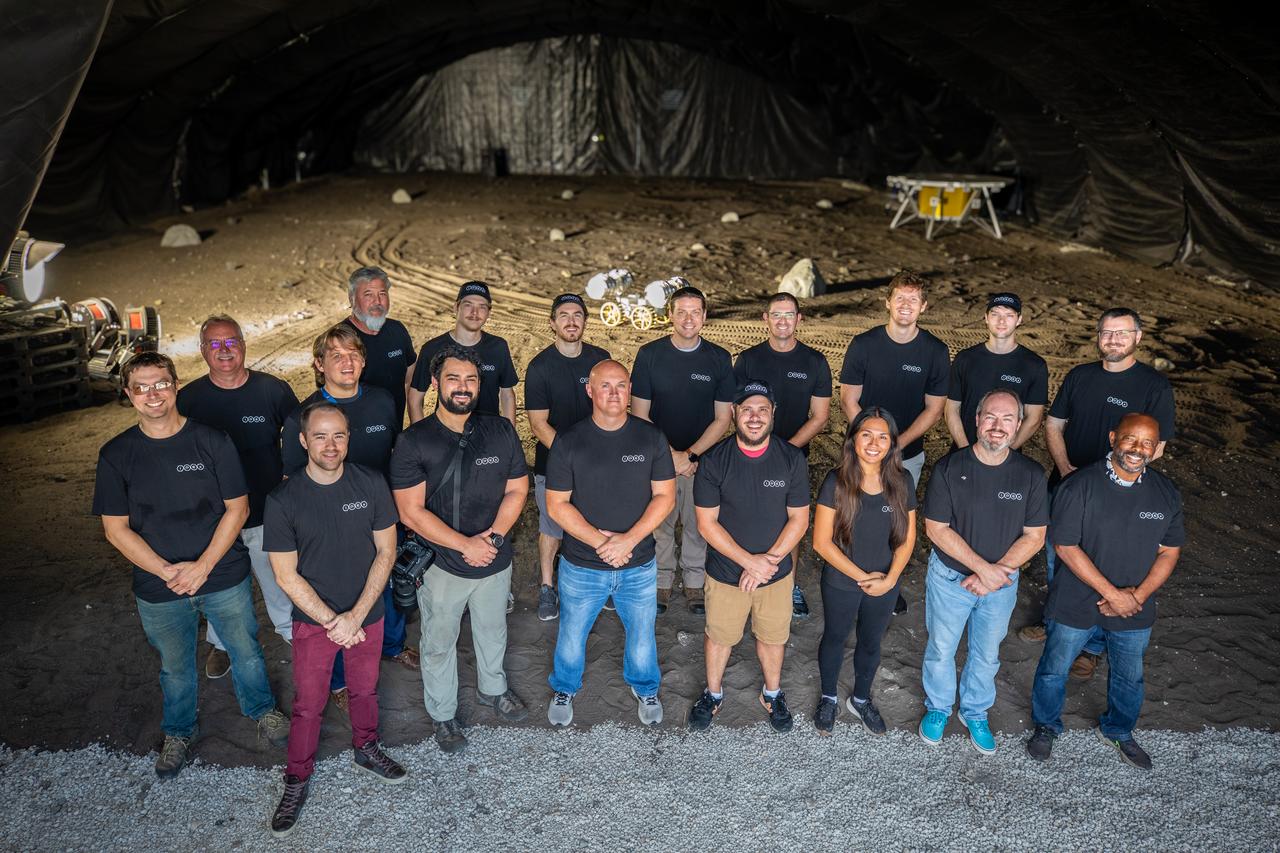
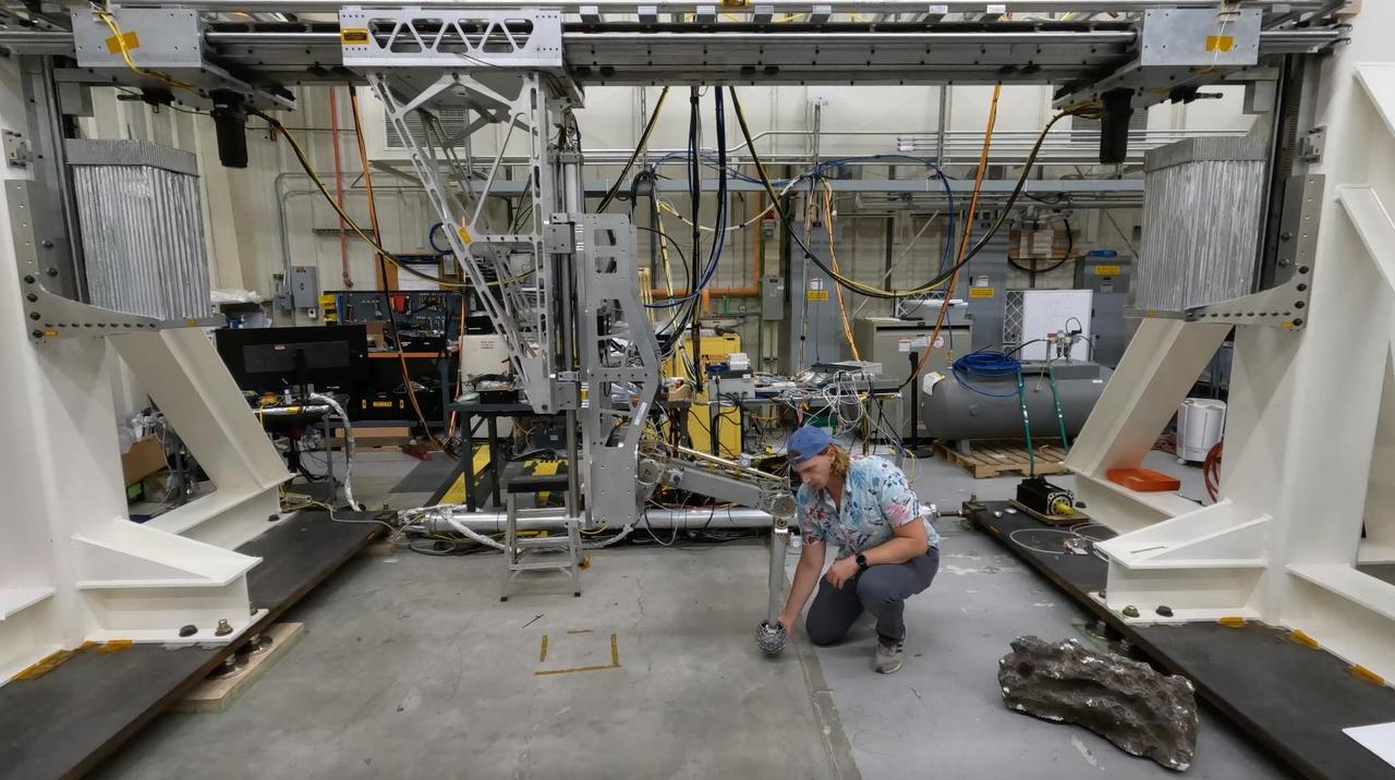
A team from the Granular Mechanics and Regolith Operations lab who developed and tested NASA’s ISRU Pilot Excavator (IPEx) pose for a photo on Friday, Aug. 30, 2024, in a testbed located at NASA’s Kennedy Space Center in Florida. IPEx functions as both an excavator and a dump truck to mine and transport lunar regolith, the loose rocky material on the Moon’s surface, which is crucial for future lunar missions and In-Situ Resource Utilization (ISRU) processes. This dual capability makes IPEx an indispensable tool for sustainable lunar exploration.
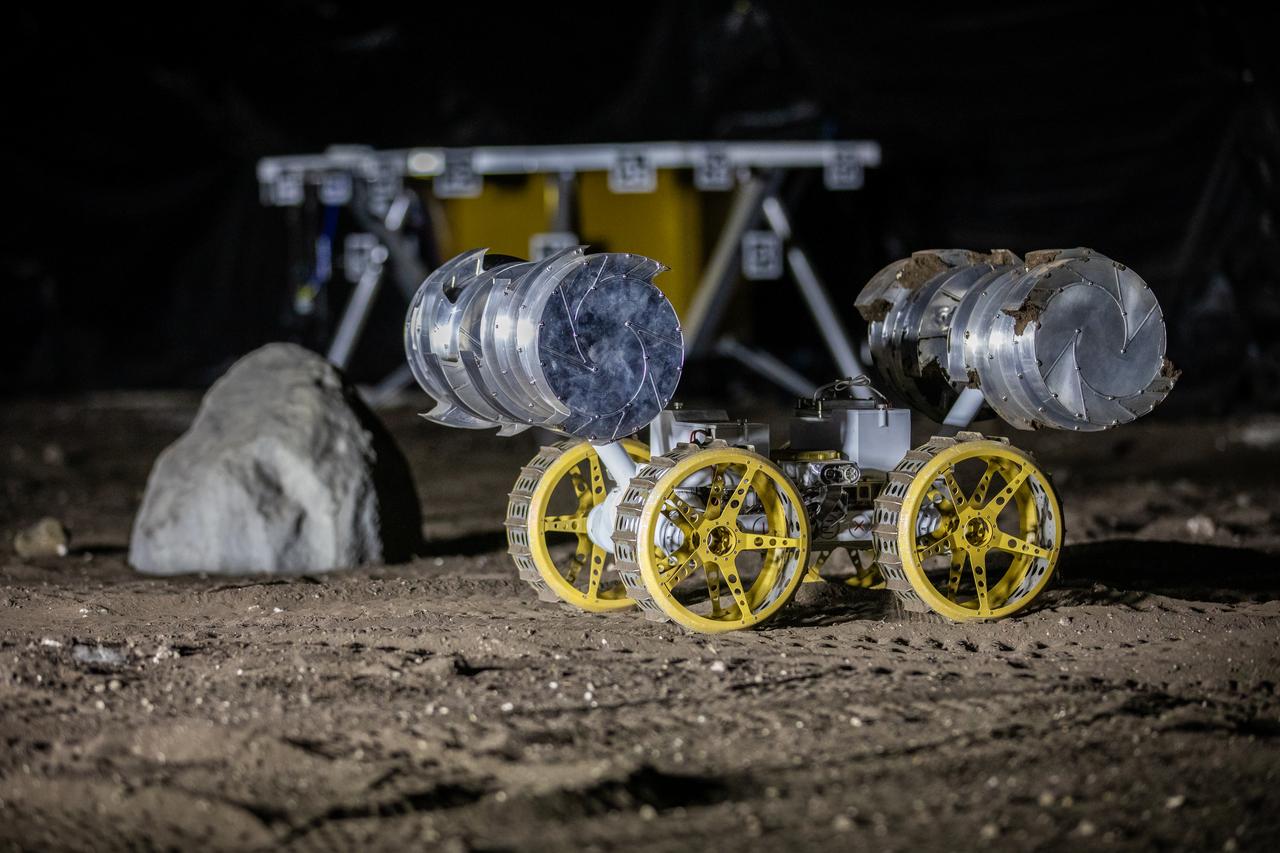
NASA’s ISRU Pilot Excavator (IPEx) performs a simulated lunar mission in a testbed at the agency’s Kennedy Space Center on Friday, Aug. 30, 2024. IPEx functions as both an excavator and a dump truck to mine and transport lunar regolith, the loose rocky material on the Moon’s surface, which is crucial for future lunar missions and In-Situ Resource Utilization (ISRU) processes. This dual capability makes IPEx an indispensable tool for sustainable lunar exploration.
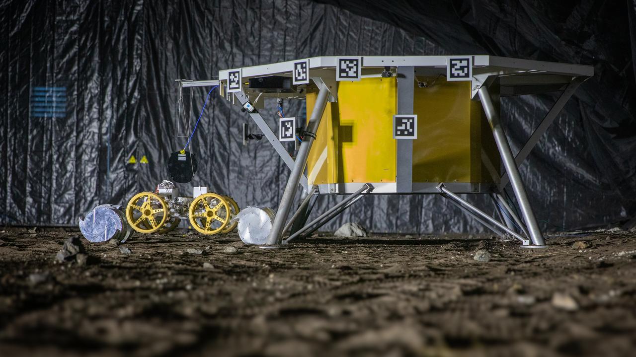
NASA’s ISRU Pilot Excavator (IPEx) performs a simulated lunar mission in a testbed at the agency’s Kennedy Space Center on Friday, Aug. 30, 2024. IPEx functions as both an excavator and a dump truck to mine and transport lunar regolith, the loose rocky material on the Moon’s surface, which is crucial for future lunar missions and In-Situ Resource Utilization (ISRU) processes. This dual capability makes IPEx an indispensable tool for sustainable lunar exploration.
Engineer Matthew Cameron-Hooper performs a checkout on some systems of the Europa Lander landing gear testbed at NASA's Jet Propulsion Laboratory in Southern California on May 27, 2022. Europa Lander is a concept for a potential future mission that would look for signs of life in the icy surface material of Jupiter's moon Europa. The moon is thought to contain a global ocean of salty water beneath its frozen crust. If life exists in that ocean, signs of its existence called biosignatures could potentially find their way to the surface. In this mission concept, a spacecraft would land on Europa and collect and study samples from about 4 inches (10 centimeters) beneath the surface, looking for signs of life. The Europa Lander landing gear testbed was developed to test and inform the design of the landing gear for the spacecraft: It mimics the landing loads and ground interaction forces that a single flight landing gear would experience when touching down on the Europan surface. It does this by using gravity offloading to simulate the reduced gravity on Europa, and by replicating the mass and inertial properties of a flight lander as well as all the degrees of freedom that the landing gear would experience. This system checkout confirmed two critical functionalities of the testbed: low friction of the horizontal degree of freedom that carries the test landing gear, and proper functioning of the gravity offloading system. Together these functionalities ensure that only ground interaction forces cause the test landing gear to come to a stop during a test, just as a flight landing gear would experience when landing on the Europan surface. Video available at https://photojournal.jpl.nasa.gov/catalog/PIA26200
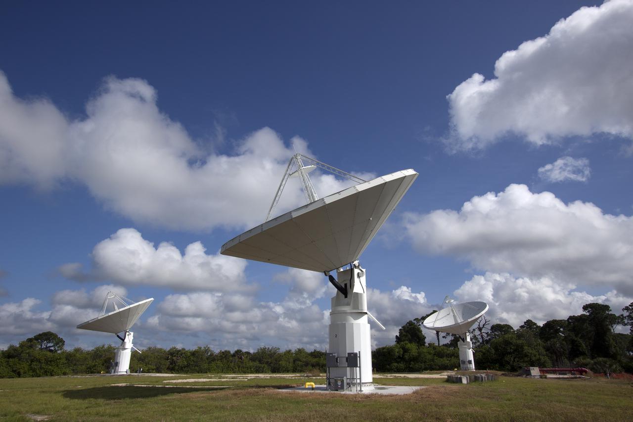
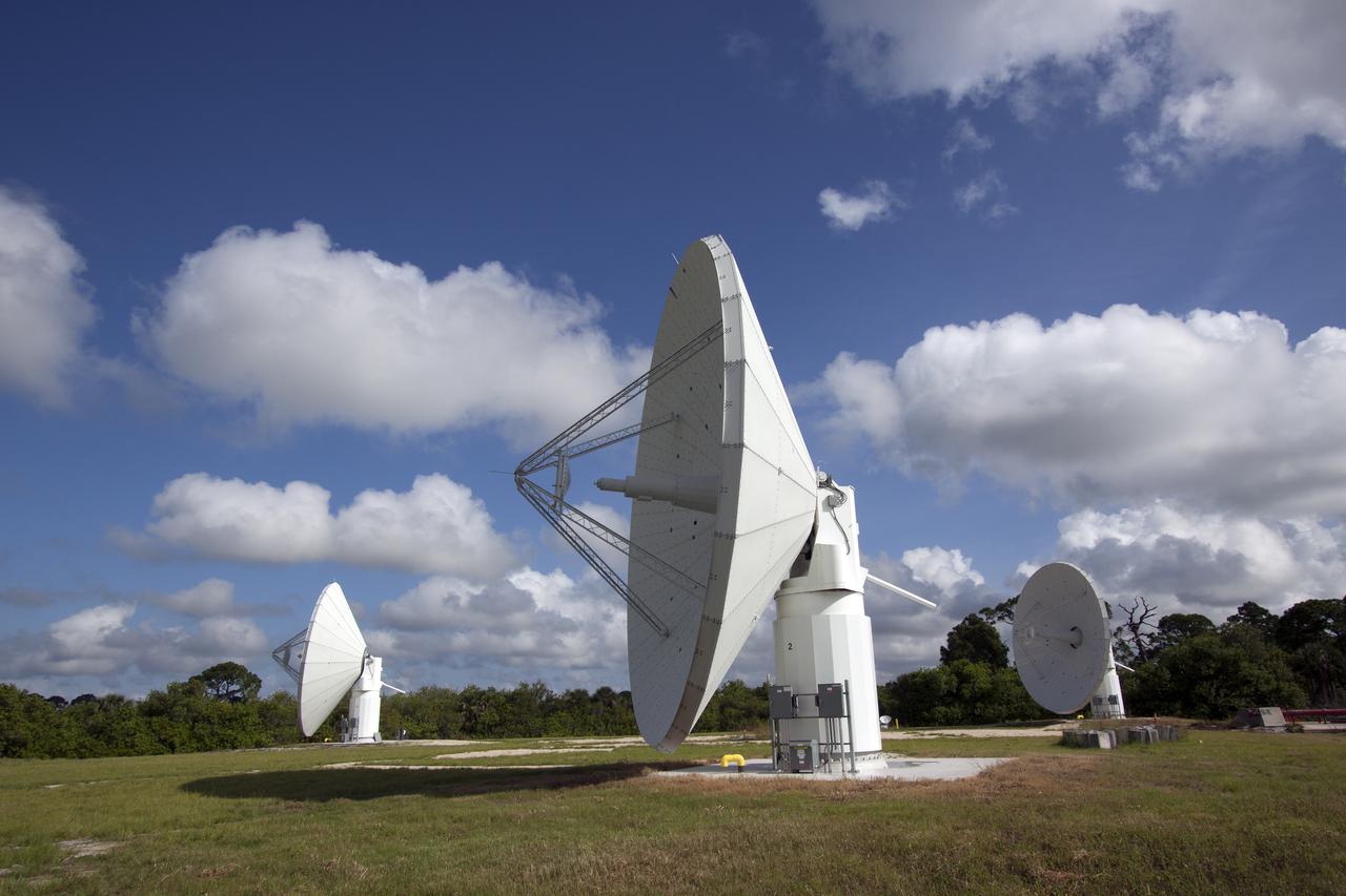
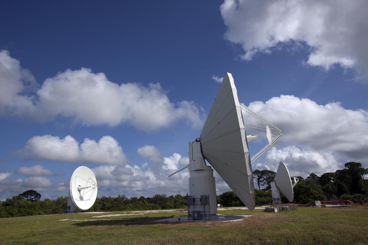
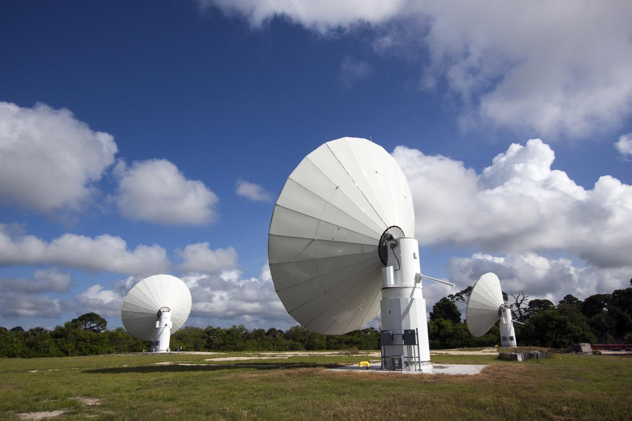
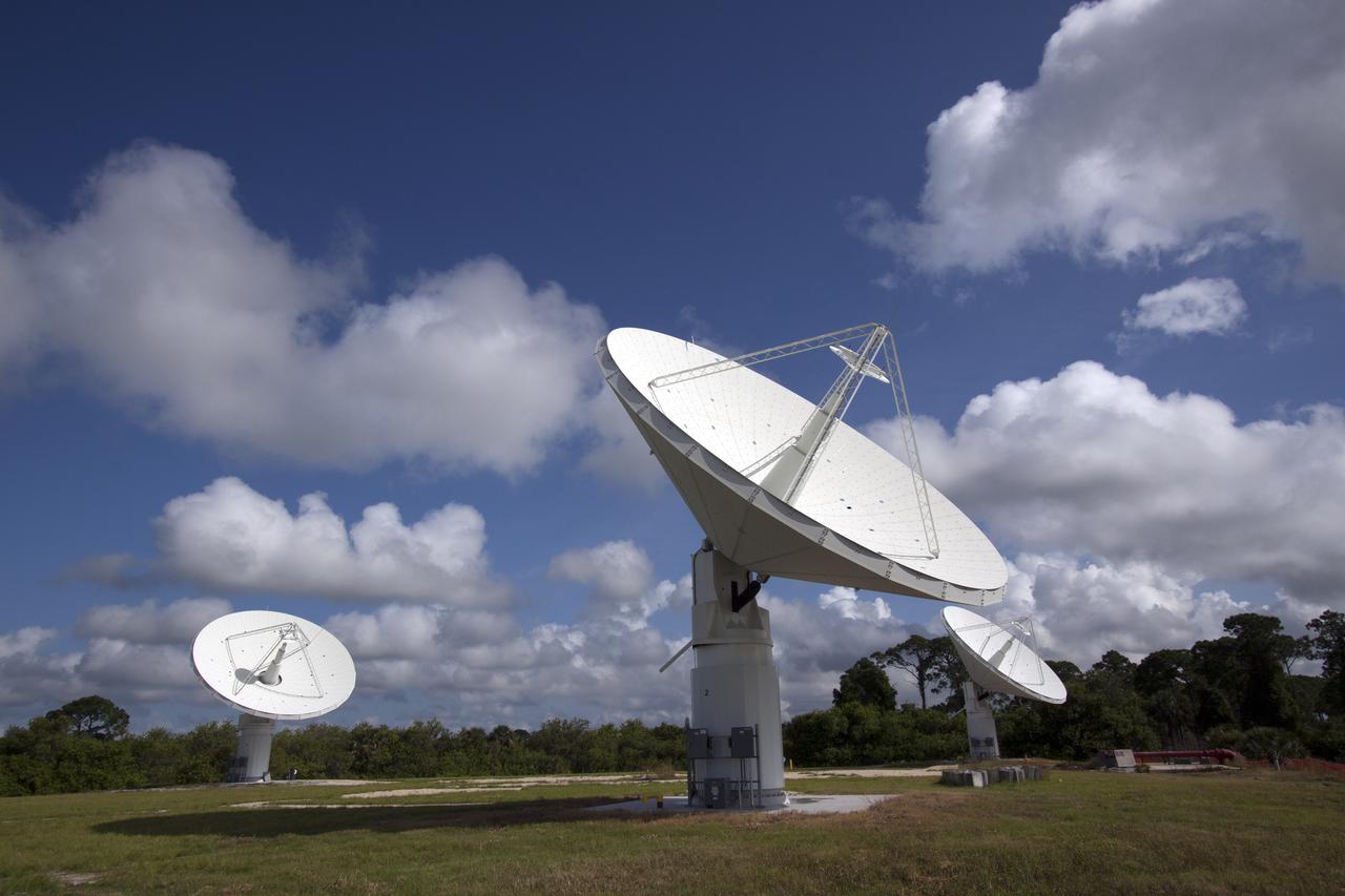
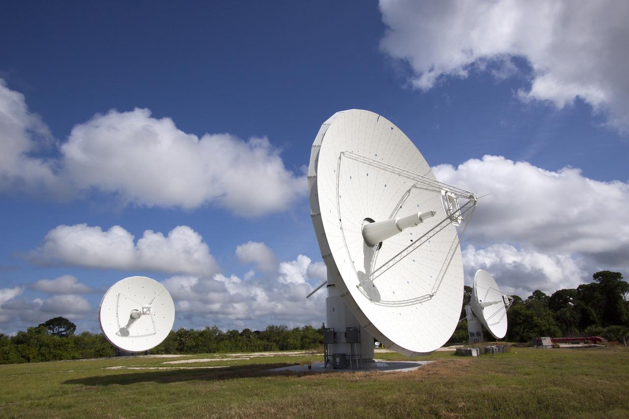
CAPE CANAVERAL, Fla. -- At NASA’s Kennedy Space Center in Florida, the three Ka-Band Objects Observation and Monitoring, or Ka-BOOM, testbed antennas are used to track the pattern of the sun during initial testing of the new system. The goal of Ka-BOOM is to prove technologies that will allow future systems to characterize near-Earth objects in terms of size, shape, rotation_tumble rate and to determine the trajectory of those objects. Radar studies can determine the trajectory 100,000 times more precisely than can optical methods. While also capable of space communication and radio science experiments, developing radar applications is the primary focus of the arrays. The 40-foot-diameter dish antenna arrays are at the site of the former Vertical Processing Facility, which has been demolished. Photo credit: NASA_Jim Grossmann
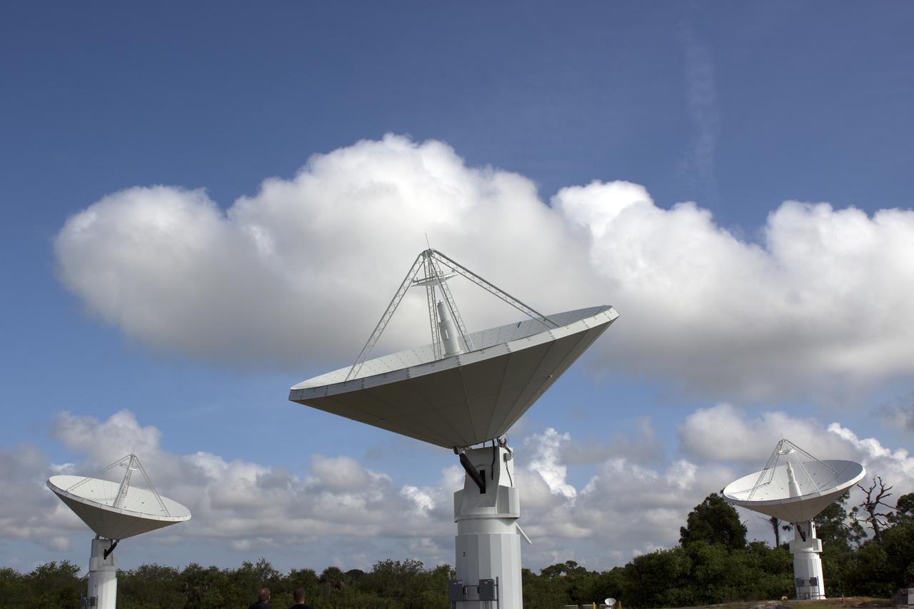
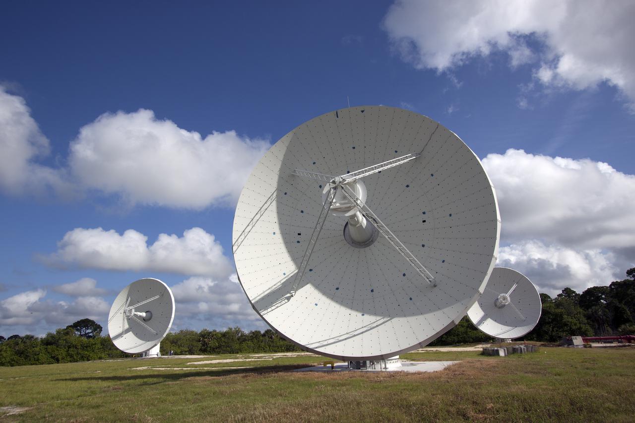
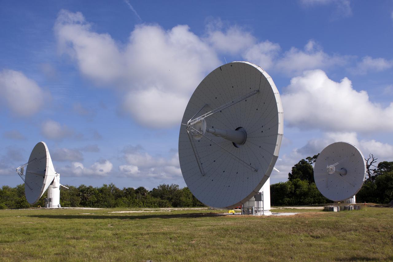
CAPE CANAVERAL, Fla. -- At NASA’s Kennedy Space Center in Florida, the three Ka-Band Objects Observation and Monitoring, or Ka-BOOM, testbed antennas are used to track the pattern of the sun during initial testing of the new system. The goal of Ka-BOOM is to prove technologies that will allow future systems to characterize near-Earth objects in terms of size, shape, rotation_tumble rate and to determine the trajectory of those objects. Radar studies can determine the trajectory 100,000 times more precisely than can optical methods. While also capable of space communication and radio science experiments, developing radar applications is the primary focus of the arrays. The 40-foot-diameter dish antenna arrays are at the site of the former Vertical Processing Facility, which has been demolished. Photo credit: NASA_Jim Grossmann
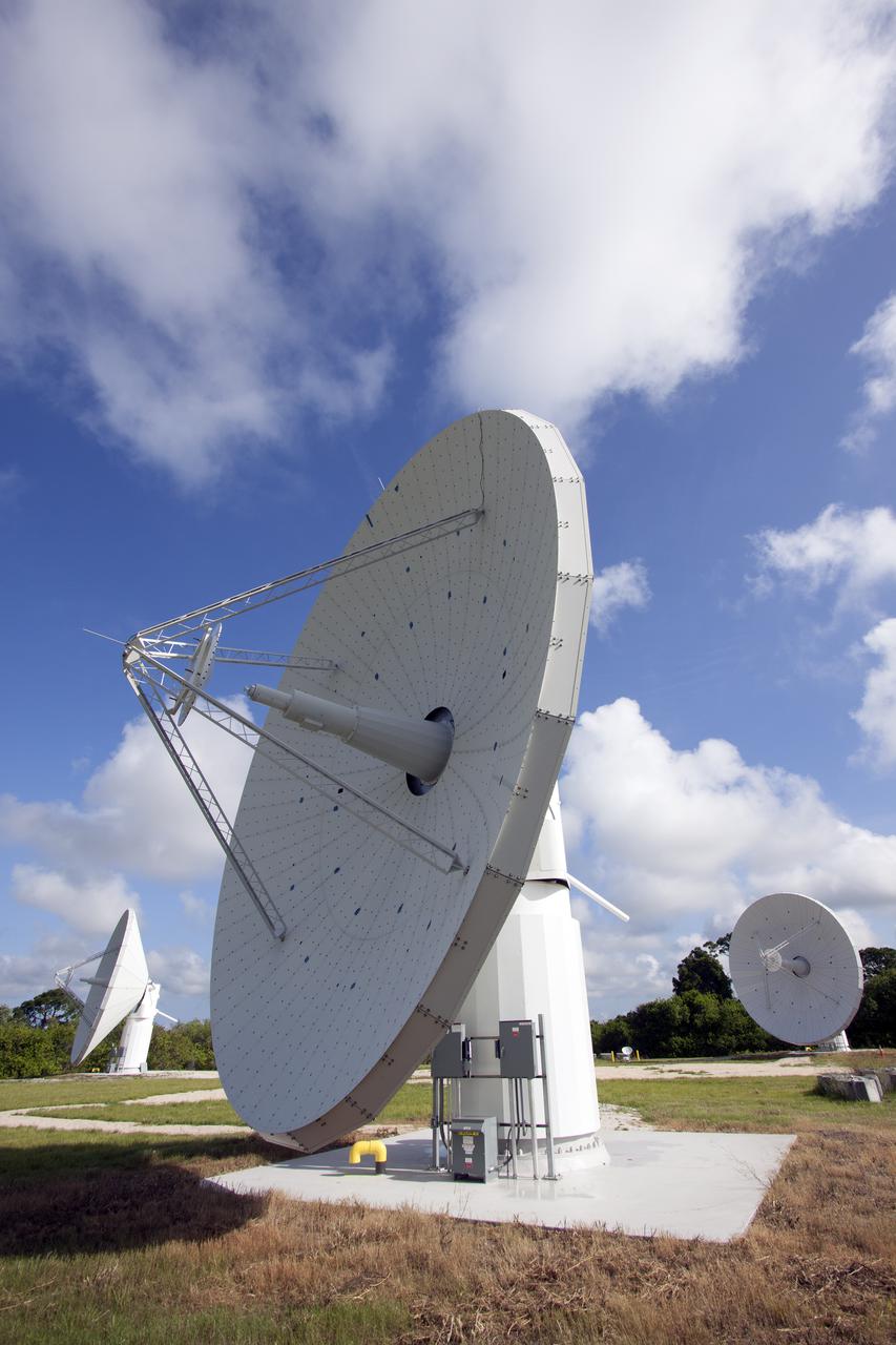
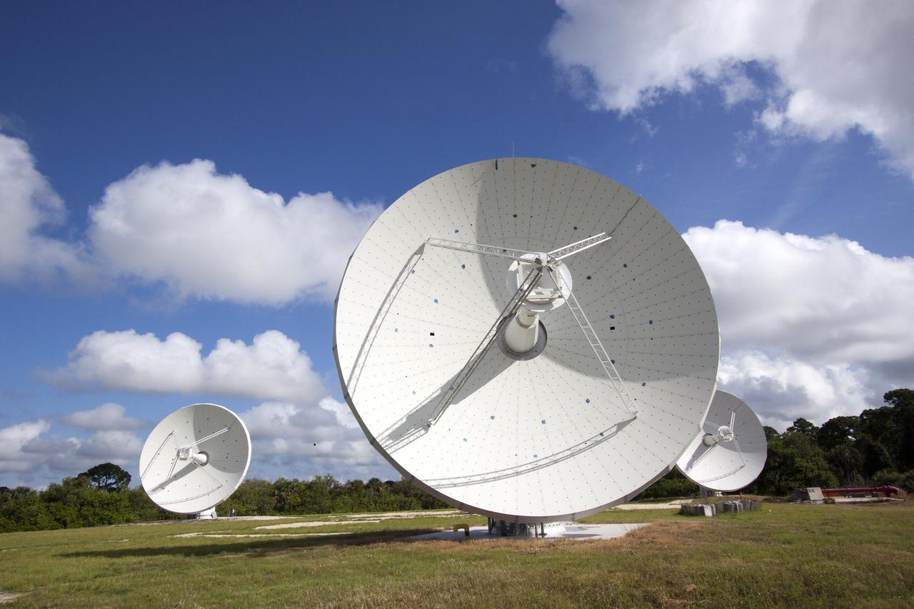
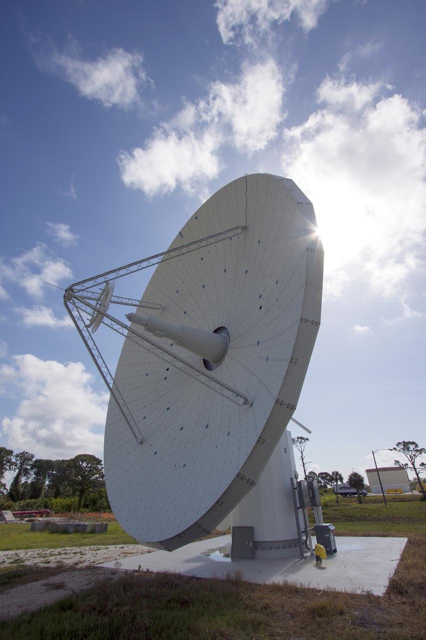
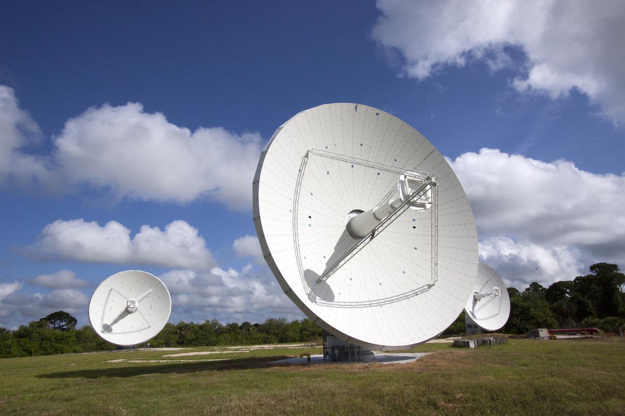
CAPE CANAVERAL, Fla. -- At NASA’s Kennedy Space Center in Florida, one of the three Ka-Band Objects Observation and Monitoring, or Ka-BOOM, testbed antennas is used to track the sun during initial testing of the new system. The goal of Ka-BOOM is to prove technologies that will allow future systems to characterize near-Earth objects in terms of size, shape, rotation_tumble rate and to determine the trajectory of those objects. Radar studies can determine the trajectory 100,000 times more precisely than can optical methods. While also capable of space communication and radio science experiments, developing radar applications is the primary focus of the arrays. The 40-foot-diameter dish antenna arrays are at the site of the former Vertical Processing Facility, which has been demolished. Photo credit: NASA_Jim Grossmann
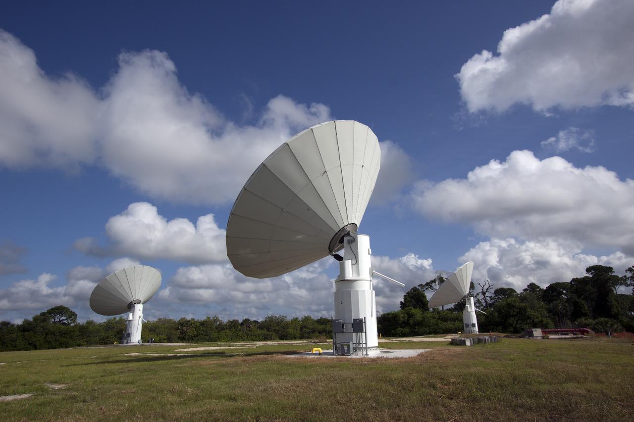
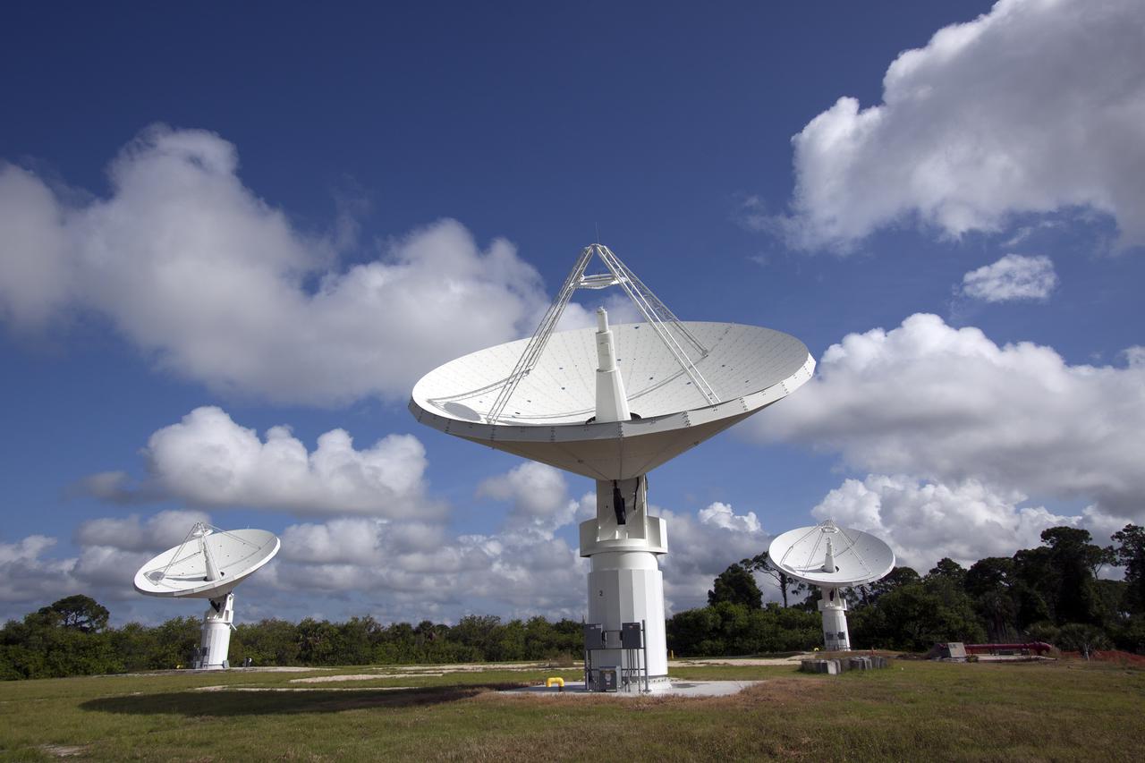
CAPE CANAVERAL, Fla. -- At NASA’s Kennedy Space Center in Florida, the three Ka-Band Objects Observation and Monitoring, or Ka-BOOM, testbed antennas are used to track the pattern of the sun during initial testing of the new system. The goal of Ka-BOOM is to prove technologies that will allow future systems to characterize near-Earth objects in terms of size, shape, rotation_tumble rate and to determine the trajectory of those objects. Radar studies can determine the trajectory 100,000 times more precisely than can optical methods. While also capable of space communication and radio science experiments, developing radar applications is the primary focus of the arrays. The 40-foot-diameter dish antenna arrays are at the site of the former Vertical Processing Facility, which has been demolished. Photo credit: NASA_Jim Grossmann
CAPE CANAVERAL, Fla. -- At NASA’s Kennedy Space Center in Florida, the three Ka-Band Objects Observation and Monitoring, or Ka-BOOM, testbed antennas are used to track the pattern of the sun during initial testing of the new system. The goal of Ka-BOOM is to prove technologies that will allow future systems to characterize near-Earth objects in terms of size, shape, rotation_tumble rate and to determine the trajectory of those objects. Radar studies can determine the trajectory 100,000 times more precisely than can optical methods. While also capable of space communication and radio science experiments, developing radar applications is the primary focus of the arrays. The 40-foot-diameter dish antenna arrays are at the site of the former Vertical Processing Facility, which has been demolished. Photo credit: NASA_Jim Grossmann
CAPE CANAVERAL, Fla. -- At NASA’s Kennedy Space Center in Florida, the three Ka-Band Objects Observation and Monitoring, or Ka-BOOM, testbed antennas are used to track the pattern of the sun during initial testing of the new system. The goal of Ka-BOOM is to prove technologies that will allow future systems to characterize near-Earth objects in terms of size, shape, rotation_tumble rate and to determine the trajectory of those objects. Radar studies can determine the trajectory 100,000 times more precisely than can optical methods. While also capable of space communication and radio science experiments, developing radar applications is the primary focus of the arrays. The 40-foot-diameter dish antenna arrays are at the site of the former Vertical Processing Facility, which has been demolished. Photo credit: NASA_Jim Grossmann
CAPE CANAVERAL, Fla. -- At NASA’s Kennedy Space Center in Florida, the three Ka-Band Objects Observation and Monitoring, or Ka-BOOM, testbed antennas are used to track the pattern of the sun during initial testing of the new system. The goal of Ka-BOOM is to prove technologies that will allow future systems to characterize near-Earth objects in terms of size, shape, rotation_tumble rate and to determine the trajectory of those objects. Radar studies can determine the trajectory 100,000 times more precisely than can optical methods. While also capable of space communication and radio science experiments, developing radar applications is the primary focus of the arrays. The 40-foot-diameter dish antenna arrays are at the site of the former Vertical Processing Facility, which has been demolished. Photo credit: NASA_Jim Grossmann
CAPE CANAVERAL, Fla. -- At NASA’s Kennedy Space Center in Florida, the three Ka-Band Objects Observation and Monitoring, or Ka-BOOM, testbed antennas are used to track the pattern of the sun during initial testing of the new system. The goal of Ka-BOOM is to prove technologies that will allow future systems to characterize near-Earth objects in terms of size, shape, rotation_tumble rate and to determine the trajectory of those objects. Radar studies can determine the trajectory 100,000 times more precisely than can optical methods. While also capable of space communication and radio science experiments, developing radar applications is the primary focus of the arrays. The 40-foot-diameter dish antenna arrays are at the site of the former Vertical Processing Facility, which has been demolished. Photo credit: NASA_Jim Grossmann
CAPE CANAVERAL, Fla. -- At NASA’s Kennedy Space Center in Florida, the three Ka-Band Objects Observation and Monitoring, or Ka-BOOM, testbed antennas are used to track the pattern of the sun during initial testing of the new system. The goal of Ka-BOOM is to prove technologies that will allow future systems to characterize near-Earth objects in terms of size, shape, rotation_tumble rate and to determine the trajectory of those objects. Radar studies can determine the trajectory 100,000 times more precisely than can optical methods. While also capable of space communication and radio science experiments, developing radar applications is the primary focus of the arrays. The 40-foot-diameter dish antenna arrays are at the site of the former Vertical Processing Facility, which has been demolished. Photo credit: NASA_Jim Grossmann
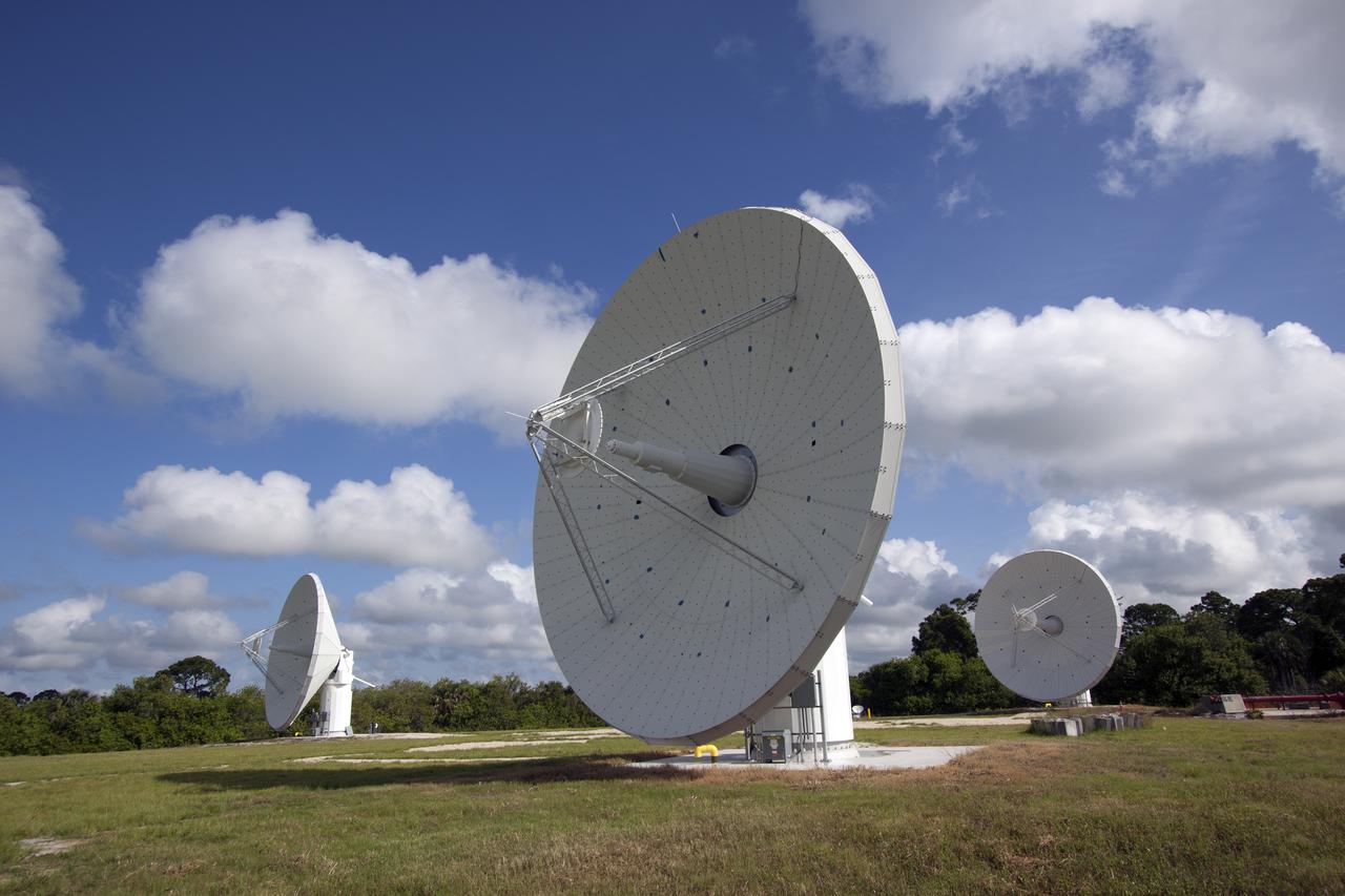
CAPE CANAVERAL, Fla. -- At NASA’s Kennedy Space Center in Florida, one of the three Ka-Band Objects Observation and Monitoring, or Ka-BOOM, testbed antennas is used to track the pattern of the sun during initial testing of the new system. The goal of Ka-BOOM is to prove technologies that will allow future systems to characterize near-Earth objects in terms of size, shape, rotation_tumble rate and to determine the trajectory of those objects. Radar studies can determine the trajectory 100,000 times more precisely than can optical methods. While also capable of space communication and radio science experiments, developing radar applications is the primary focus of the arrays. The 40-foot-diameter dish antenna arrays are at the site of the former Vertical Processing Facility, which has been demolished. Photo credit: NASA_Jim Grossmann
CAPE CANAVERAL, Fla. -- At NASA’s Kennedy Space Center in Florida, one of the three Ka-Band Objects Observation and Monitoring, or Ka-BOOM, testbed antennas is used to track the pattern of the sun during initial testing of the new system. The goal of Ka-BOOM is to prove technologies that will allow future systems to characterize near-Earth objects in terms of size, shape, rotation_tumble rate and to determine the trajectory of those objects. Radar studies can determine the trajectory 100,000 times more precisely than can optical methods. While also capable of space communication and radio science experiments, developing radar applications is the primary focus of the arrays. The 40-foot-diameter dish antenna arrays are at the site of the former Vertical Processing Facility, which has been demolished. Photo credit: NASA_Jim Grossmann
CAPE CANAVERAL, Fla. -- At NASA’s Kennedy Space Center in Florida, the three Ka-Band Objects Observation and Monitoring, or Ka-BOOM, testbed antennas are used to track the pattern of the sun during initial testing of the new system. The goal of Ka-BOOM is to prove technologies that will allow future systems to characterize near-Earth objects in terms of size, shape, rotation_tumble rate and to determine the trajectory of those objects. Radar studies can determine the trajectory 100,000 times more precisely than can optical methods. While also capable of space communication and radio science experiments, developing radar applications is the primary focus of the arrays. The 40-foot-diameter dish antenna arrays are at the site of the former Vertical Processing Facility, which has been demolished. Photo credit: NASA_Jim Grossmann
CAPE CANAVERAL, Fla. -- At NASA’s Kennedy Space Center in Florida, one of the three Ka-Band Objects Observation and Monitoring, or Ka-BOOM, testbed antennas is used to track the sun during initial testing of the new system. The goal of Ka-BOOM is to prove technologies that will allow future systems to characterize near-Earth objects in terms of size, shape, rotation_tumble rate and to determine the trajectory of those objects. Radar studies can determine the trajectory 100,000 times more precisely than can optical methods. While also capable of space communication and radio science experiments, developing radar applications is the primary focus of the arrays. The 40-foot-diameter dish antenna arrays are at the site of the former Vertical Processing Facility, which has been demolished. Photo credit: NASA_Jim Grossmann
CAPE CANAVERAL, Fla. -- At NASA’s Kennedy Space Center in Florida, the three Ka-Band Objects Observation and Monitoring, or Ka-BOOM, testbed antennas are used to track the pattern of the sun during initial testing of the new system. The goal of Ka-BOOM is to prove technologies that will allow future systems to characterize near-Earth objects in terms of size, shape, rotation_tumble rate and to determine the trajectory of those objects. Radar studies can determine the trajectory 100,000 times more precisely than can optical methods. While also capable of space communication and radio science experiments, developing radar applications is the primary focus of the arrays. The 40-foot-diameter dish antenna arrays are at the site of the former Vertical Processing Facility, which has been demolished. Photo credit: NASA_Jim Grossmann
CAPE CANAVERAL, Fla. -- At NASA’s Kennedy Space Center in Florida, the three Ka-Band Objects Observation and Monitoring, or Ka-BOOM, testbed antennas are used to track the pattern of the sun during initial testing of the new system. The goal of Ka-BOOM is to prove technologies that will allow future systems to characterize near-Earth objects in terms of size, shape, rotation_tumble rate and to determine the trajectory of those objects. Radar studies can determine the trajectory 100,000 times more precisely than can optical methods. While also capable of space communication and radio science experiments, developing radar applications is the primary focus of the arrays. The 40-foot-diameter dish antenna arrays are at the site of the former Vertical Processing Facility, which has been demolished. Photo credit: NASA_Jim Grossmann
CAPE CANAVERAL, Fla. -- At NASA’s Kennedy Space Center in Florida, the three Ka-Band Objects Observation and Monitoring, or Ka-BOOM, testbed antennas are used to track the pattern of the sun during initial testing of the new system. The goal of Ka-BOOM is to prove technologies that will allow future systems to characterize near-Earth objects in terms of size, shape, rotation_tumble rate and to determine the trajectory of those objects. Radar studies can determine the trajectory 100,000 times more precisely than can optical methods. While also capable of space communication and radio science experiments, developing radar applications is the primary focus of the arrays. The 40-foot-diameter dish antenna arrays are at the site of the former Vertical Processing Facility, which has been demolished. Photo credit: NASA_Jim Grossmann
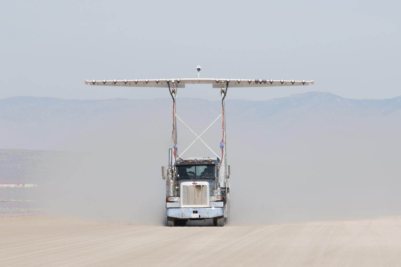
Engineers gather aerodynamic data on the integrated experimental testbed without the electric motor propellers.
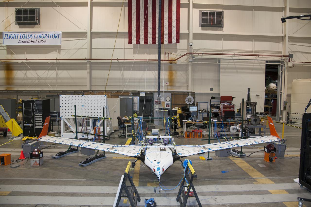
The X-56 Multi-Utility Technology Testbed (MUTT) undergoes ground vibration tests in Armstrong's Flight Loads Laboratory.
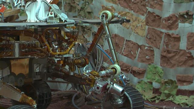
Footage taken at the JPL In-Situ Instruments Laboratory, or testbed, shows engineers practicing the deployment of the test rover robotic arm.
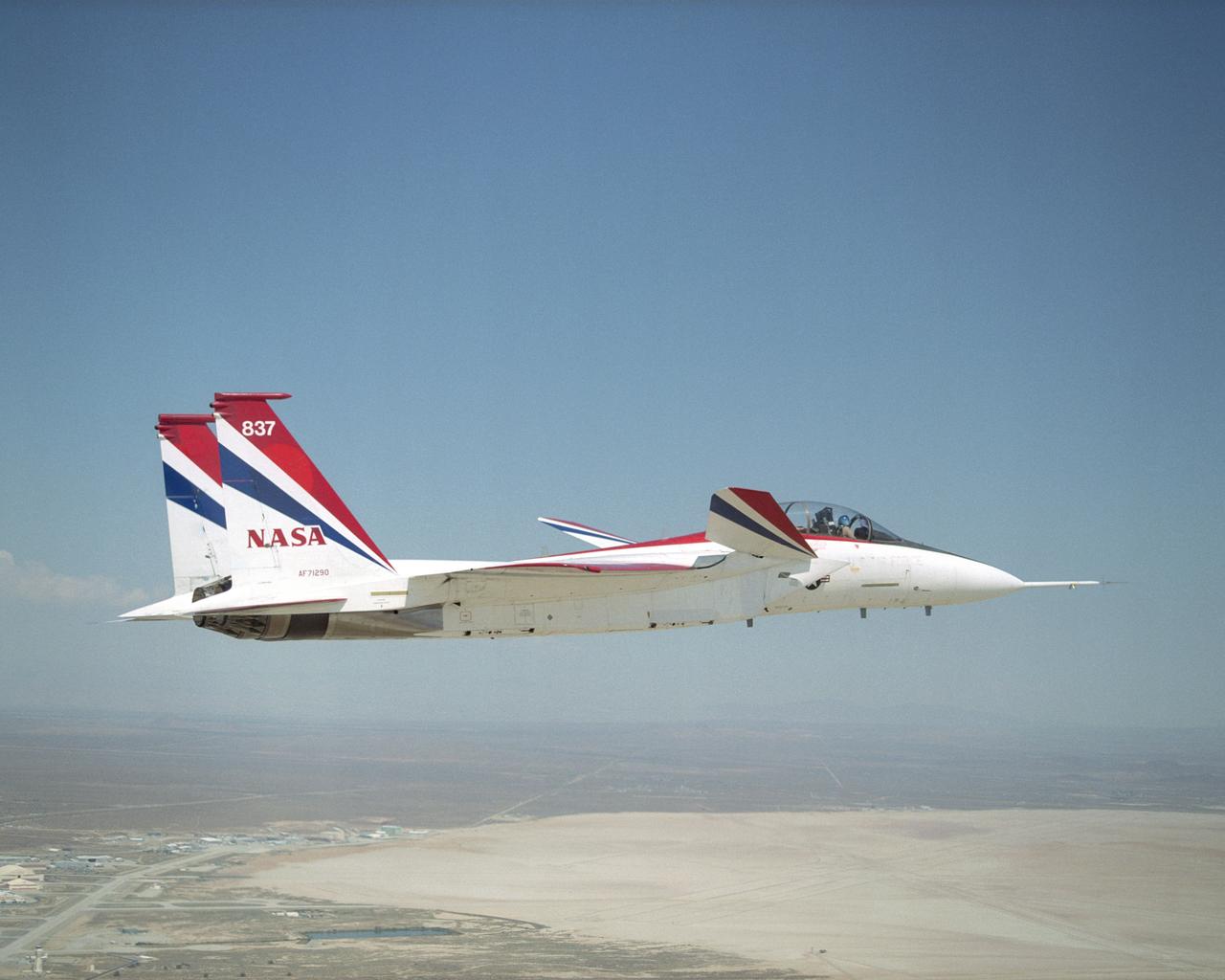
NASA Dryden's highly modified F-15B aircraft, tail number 837, serves as an Intelligent flight Control System (IFCS) research testbed aircraft.
Antennas used for the Space-Based Range Demonstration and Certification project protrude from the top of NASA's NF-15B testbed during a research flight.
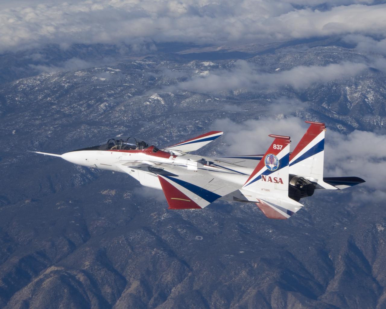
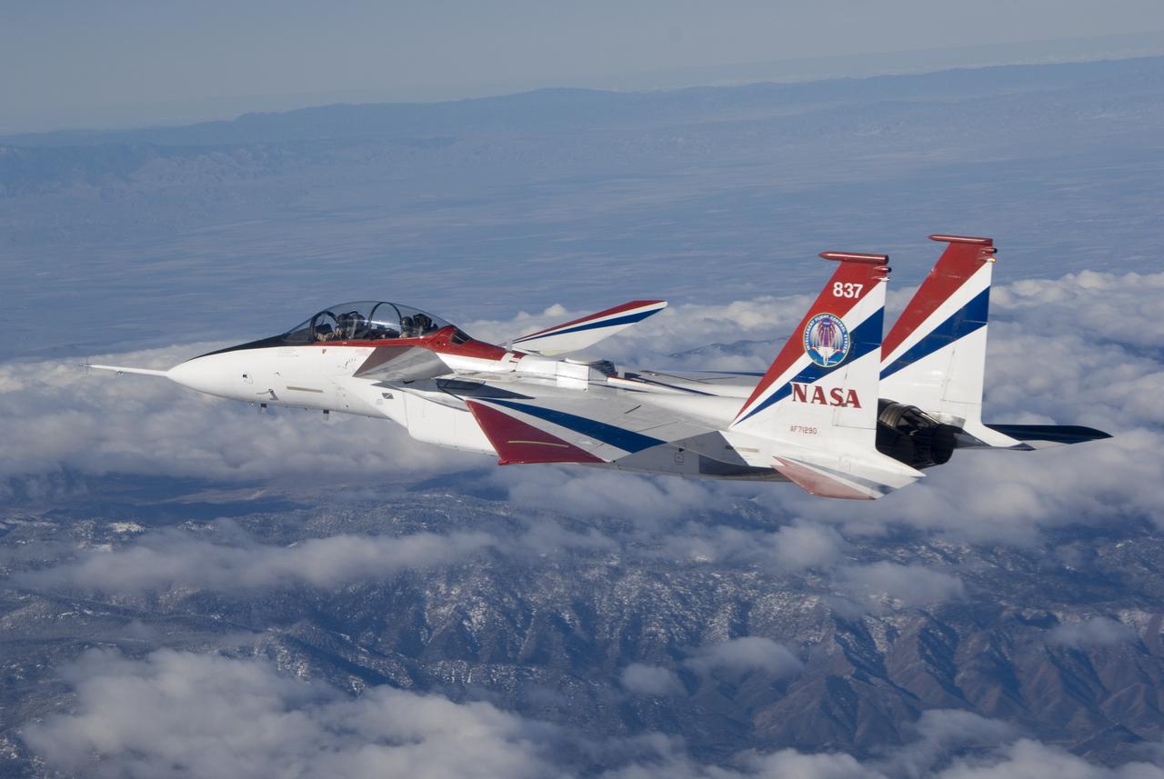
The jagged ridges of Southern California's Tehachapi Mountains form the backdrop to NASA's brightly-colored NF-15B testbed aircraft during a research mission.