
3199: Molly Pleskus (undergraduate student from Tufts University) visited the MSFC electrostatic levitation (ESL) laboratory is support of Dr. Douglas Matson’s (Tufts University) grant, “Round Robin - Thermophysical Property Measurement†(NNX17AH41G). Ms. Pleskus is researching Inconel 718 in support of future experiments on the International Space Station (ISS).
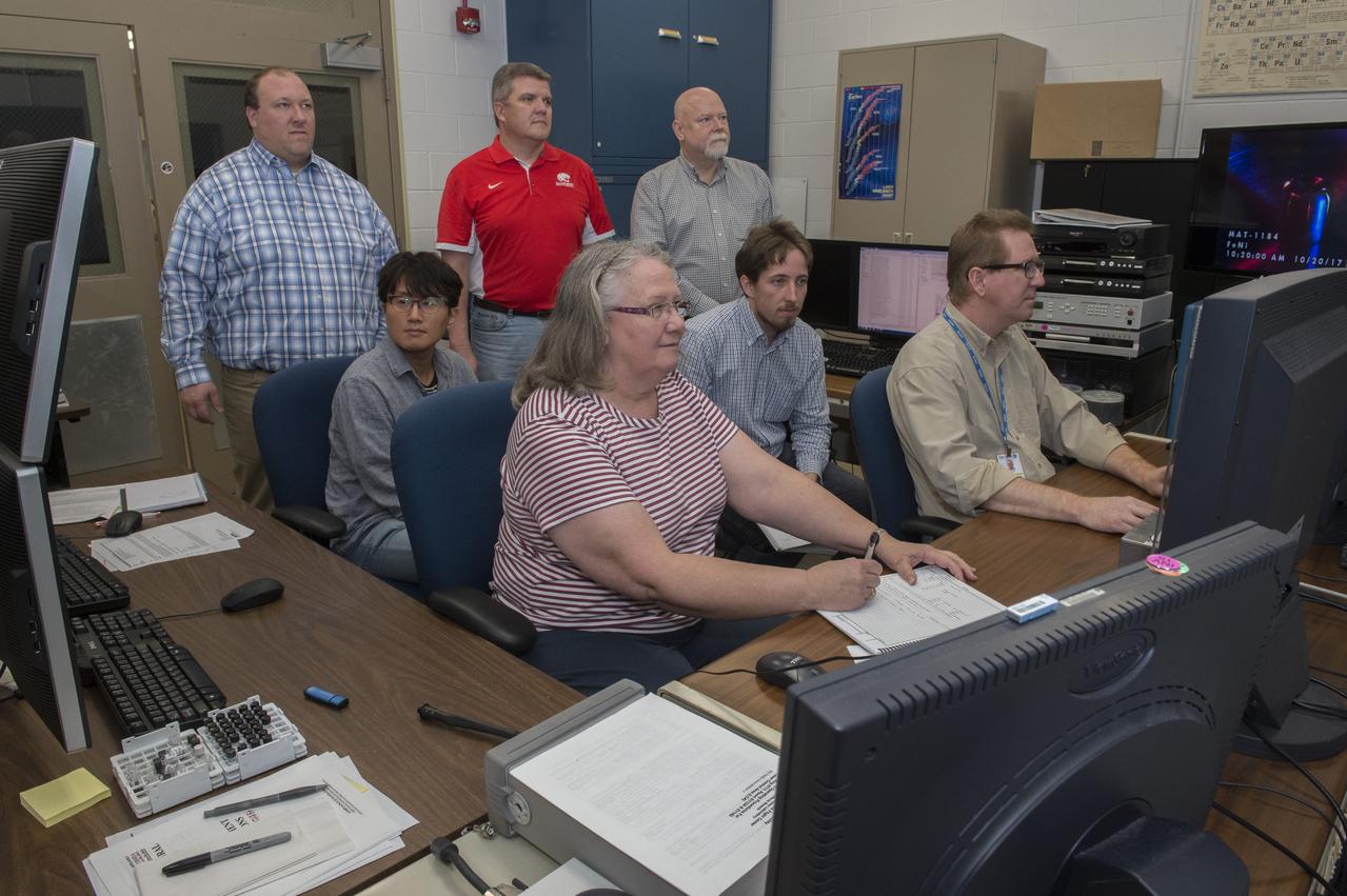
Dr. Douglas Matson, Tufts University, experimenting with an aerodynamic levitator. Dr. Matson, along with students and NASA personnel view data from tests of an aerodynamic levitator in support of his MaterialsLab experiments. back row: Michael SanSoucie (MSFC EM41), Shawn Reagan (MSFC HP30), and Douglas Matson (Tufts University) Middle row: Sangho Jeon (Tufts University) and Thomas Leitner (Graz University of Technology) Front row: Trudy Allen (MSFC EM41) and Glenn Fountain (MSFC EM41)
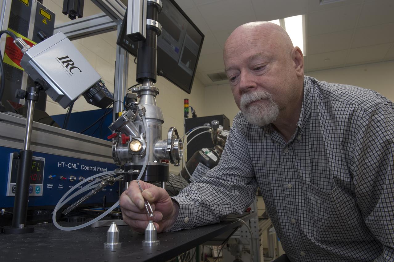
Dr. Douglas Matson (Tufts University) working with an aerodynamic levitator in support of his MaterialsLab experiments.
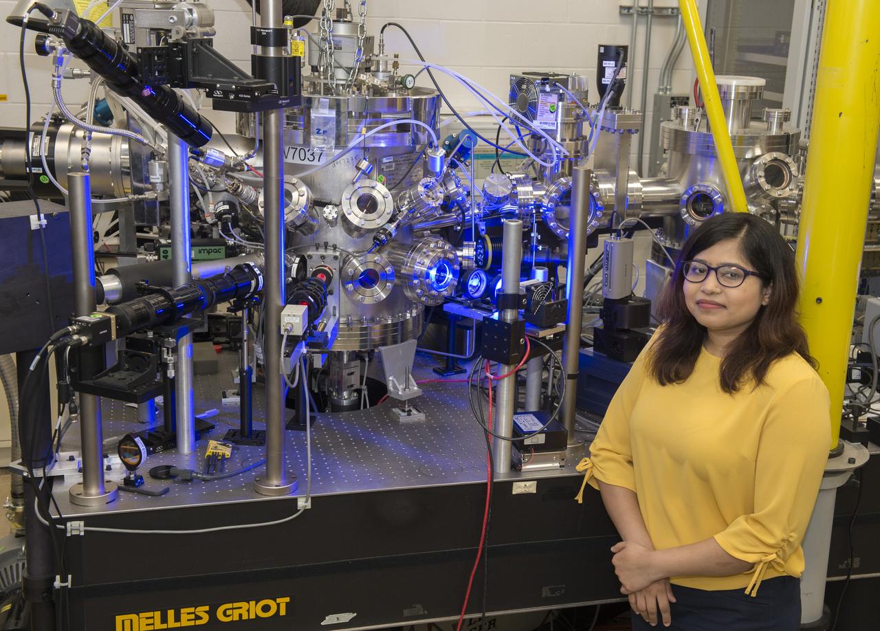
Jannatun Nawer (graduate student from Tufts University) visited the MSFC electrostatic levitation (ESL) laboratory is support of Dr. Douglas Matson’s (Tufts University) grant, “Round Robin - Thermophysical Property Measurement†(NNX17AH41G). Ms. Nawer is researching CMSX-4 Plus, a nickel-based superalloy, in support of future experiments on the International Space Station (ISS).
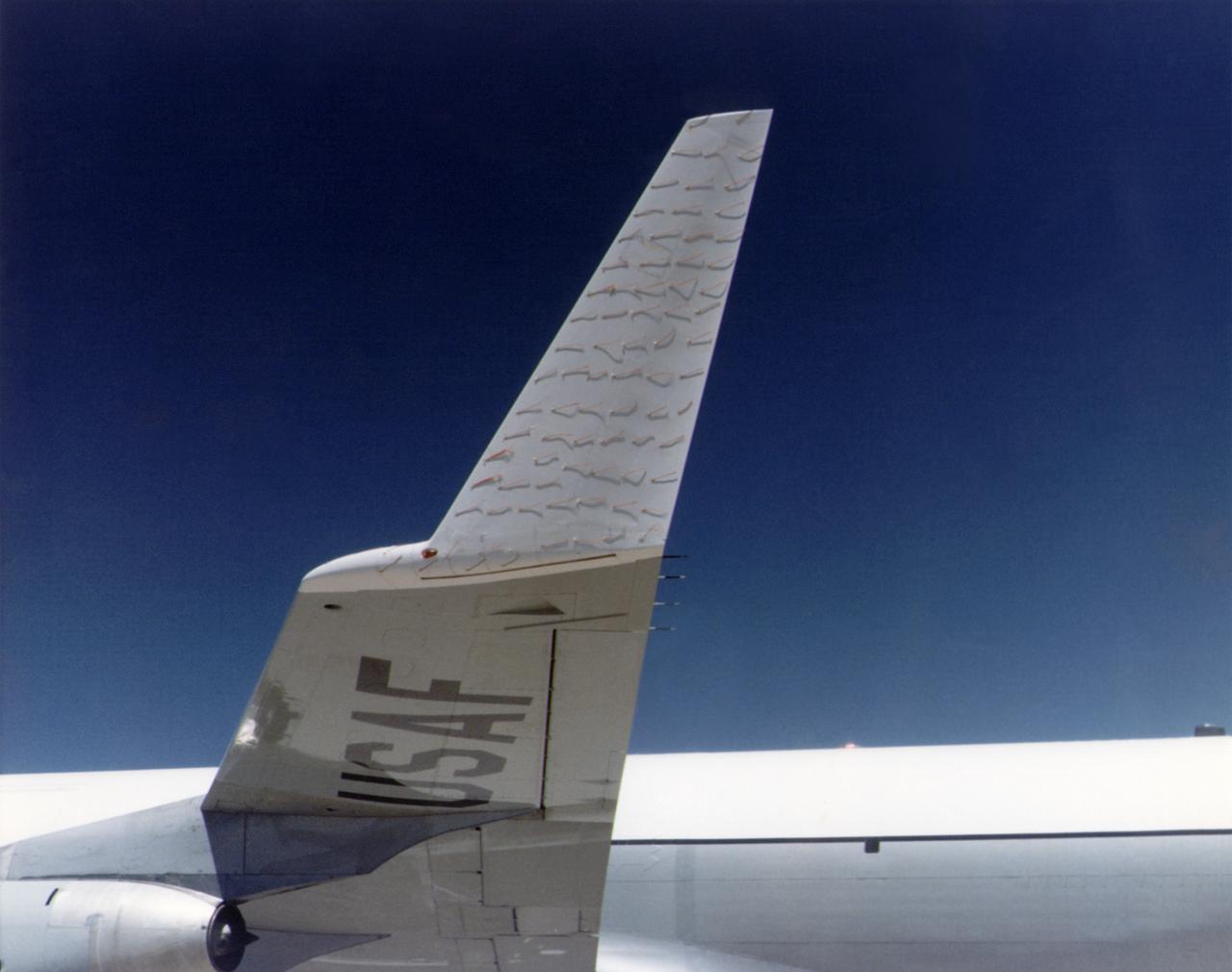
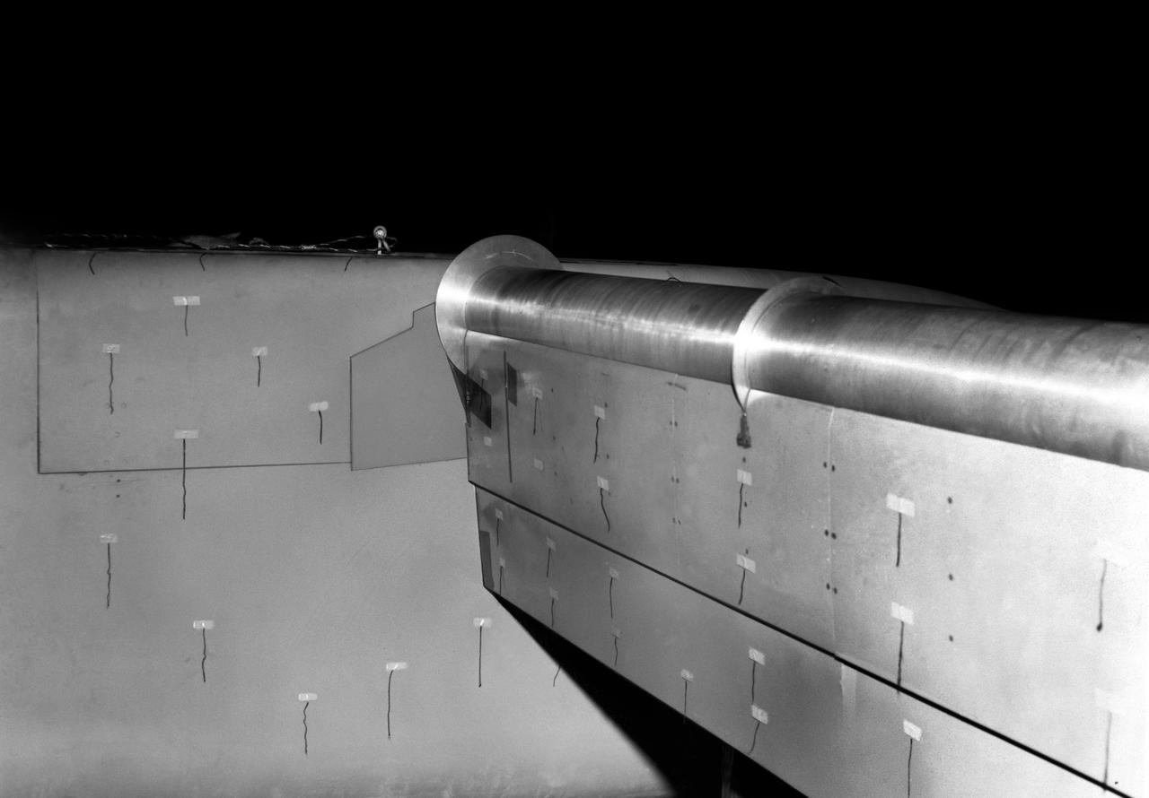
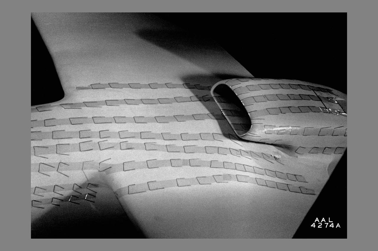
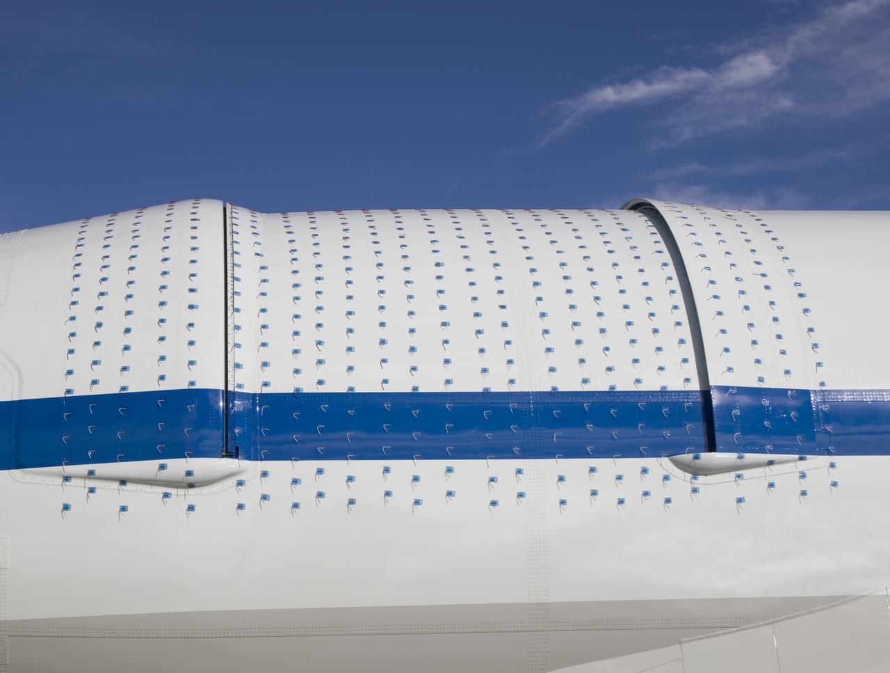
A chase plane view of the tufts on the KC-135 winglet. The use of tufts in flight research dates back to the early days of the NACA, and remains an effective means of observing airflow even today. In this procedure, rows of strings are attached to an airplane's surface, with one end of each string taped to the airplane and the other end free to swing about in the airflow. The movements of the tufts are photographed by on-board cameras or a chase plane. If the tufts are arrayed in neat rows, as seen here, then the airflow is smooth over the airplane's surface. If, however, they are moving about violently, it suggests turbulent airflow. Such motions may indicate high drag, flow separation (such as in a stall), or buffeting. In some cases, tufts will actually point forward, indicating the airflow has reversed direction.
Detail view of 4 propeller model rotating cylinder flap at 90 degrees with yarn tufts attached.
QSRA (Quite STOL Research Aircraft) NASA-715 C-8A Tufts during the CCW tests out of NASA Ames
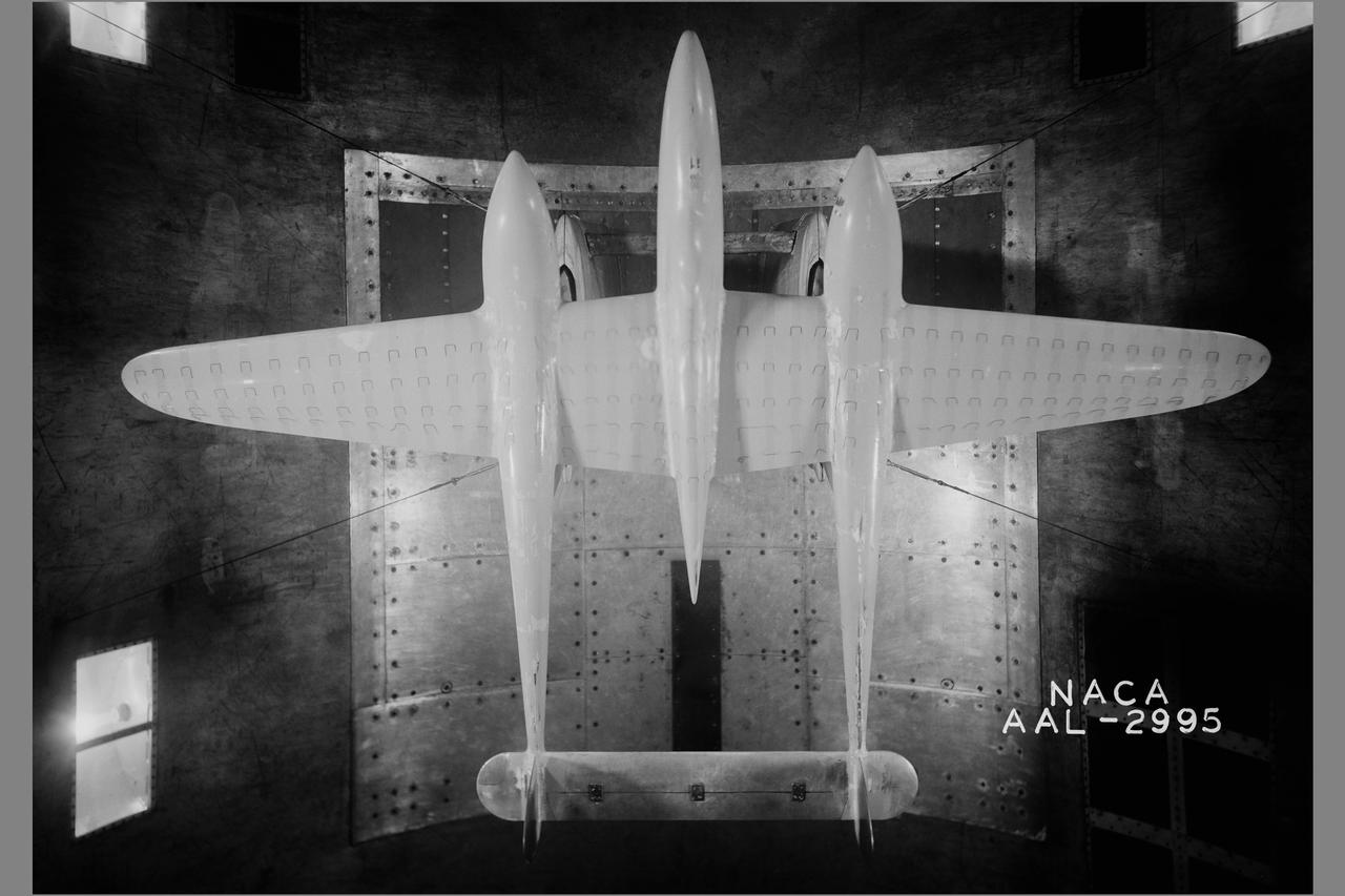
Lockheed P-38 model in 40x80ft w.t. with revised twisted wing at 10 deg. (tuft studies)
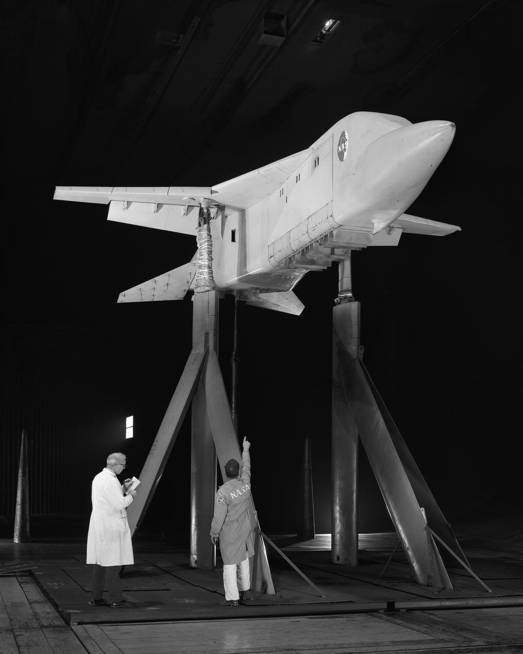
Lift engine VSTOL fighter model, 3/4 lower front view showing jet engines exit vanes. Yarn tufts attached to horizontal tail.
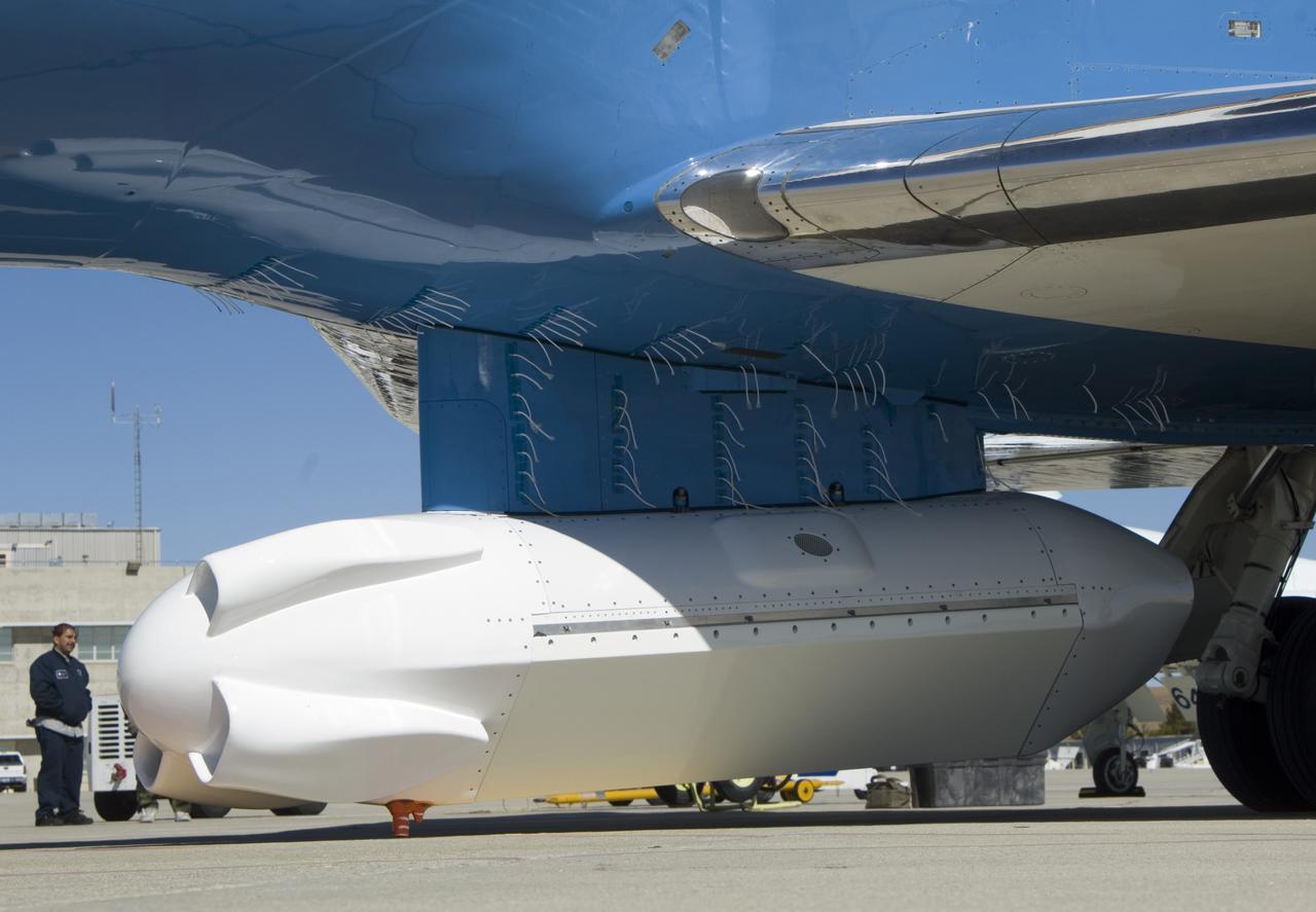
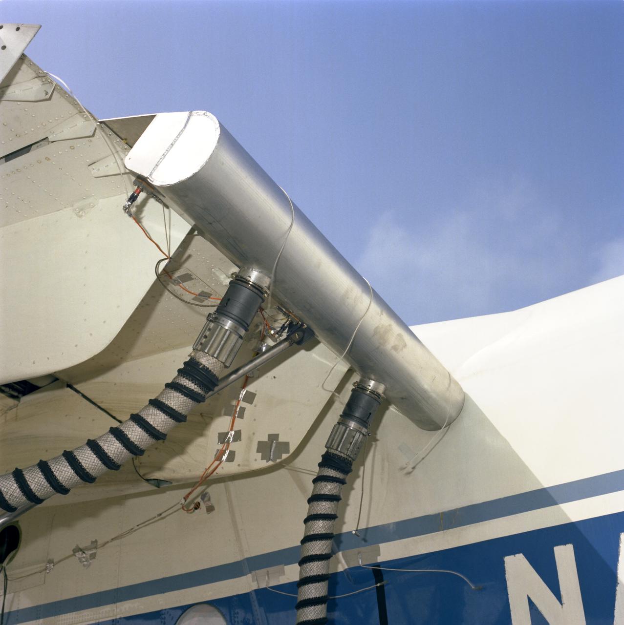
A forest of tufts are mounted on the underbelly and pylon of NASA's Gulfstream-III research aircraft to help engineers determine airflow around the UAVSAR pod.
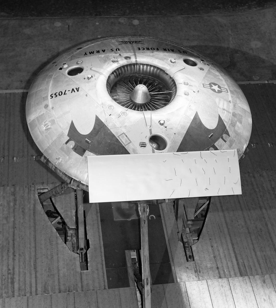
Top rear view of the avrocar with tail. Tufts (pieces of yarn) attached to top of horizontal tail. Avrocar mounted on variable height struts.
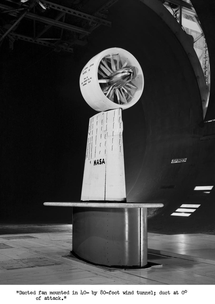
Wind Tunnel investigation of ducted fan though 180 deg angle of attack. 3/4 front view of Doak ducted fan, semi-span model with tufts.
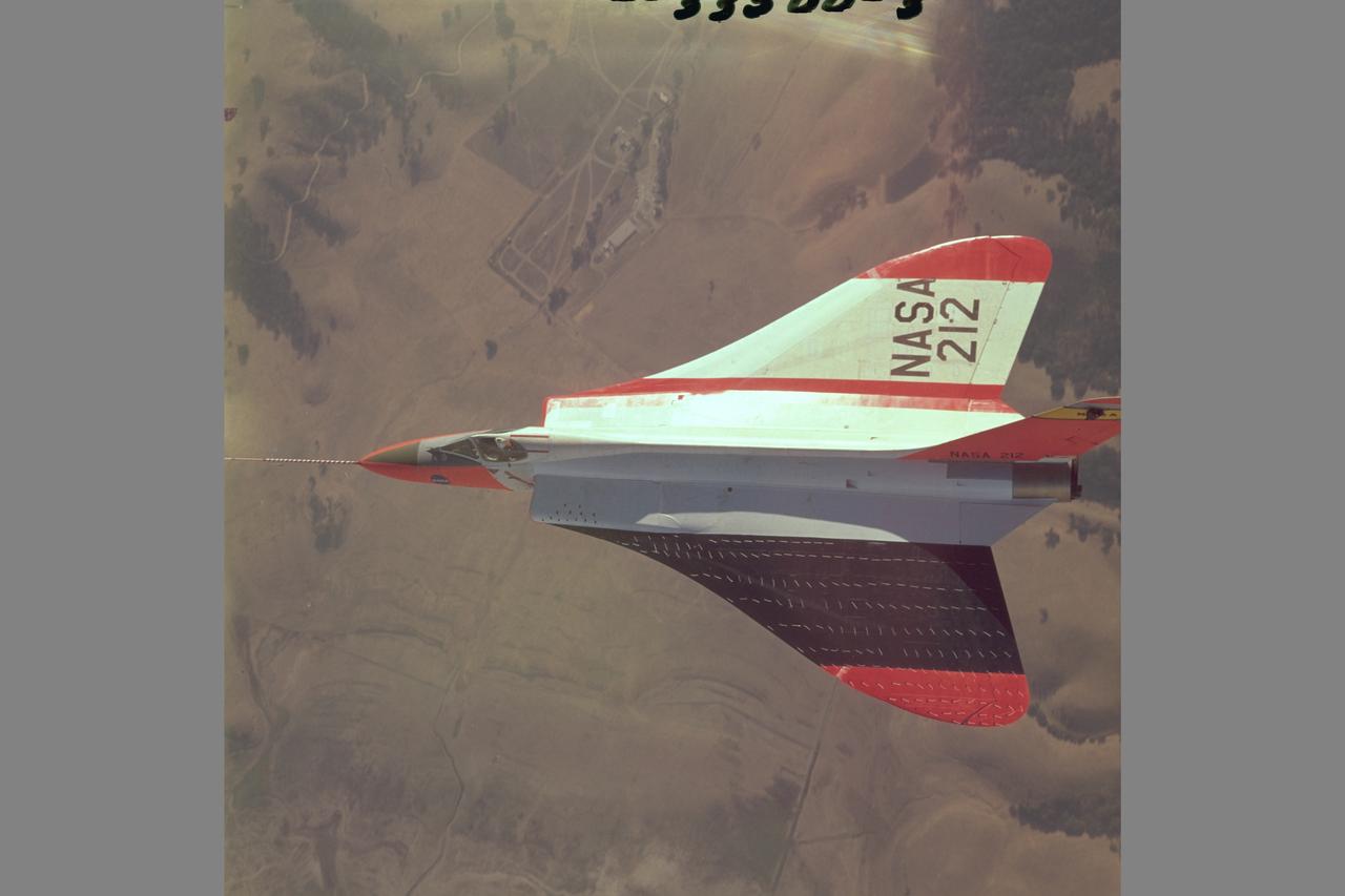
Douglas F5D Skylancer fighter modified with ogee wing planform designed for Mach 2 flight. Shown is the effect of vortex flow on wing tuft alignment in low-speed, high angle-of-attack flight.
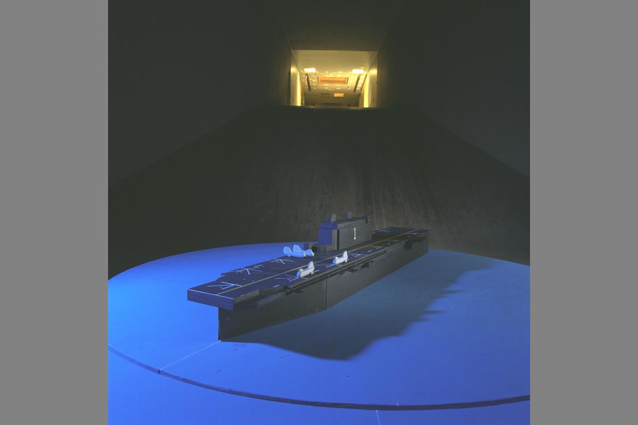
Test Setup and UltraViolet (UV) Lighting and Tufts. Ship Airwake Investigation 7 x 10 ft#2 Wind Tunnel Settling Chamber. Bridge and rotorcraft added to flight deck
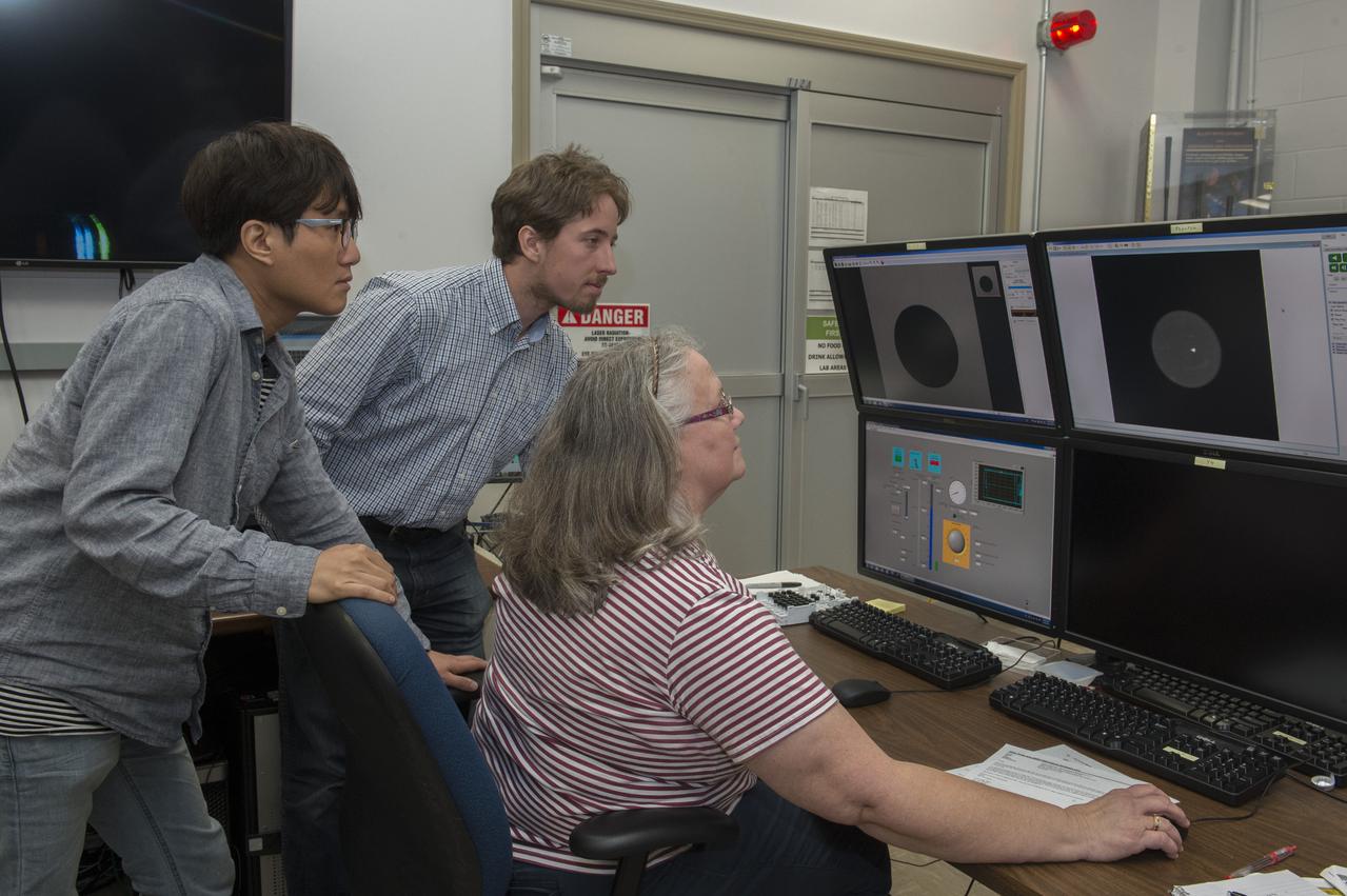
Sangho Jeon (Tufts University), Thomas Leitner (Graz University of Technology), and Trudy Allen analyze data from Dr. Douglas Matson's aerodynamic levitator in support of his MaterialsLab experiments.
North American P-51B tuft studies done in the NACA Ames Research center 16ft Transonic Wind Tunnel Radiator air scoop with oil and prestone cooler exit flaps in flush position.

Navy diver Michael Tuft (far right) and his team wait to be called for their part in Underway Recovery Test 6 aboard the USS Anchorage. The divers will be the first people astronauts aboard the Orion spacecraft see when they splash down in the Pacific Ocean after Exploration Mission-2. The testing with the NASA Recovery Team and the U.S. Navy will provide important data that is being used to improve recovery procedures and hardware ahead of Orion's next flight, Exploration Mission-1, when it splashes down in the Pacific Ocean.
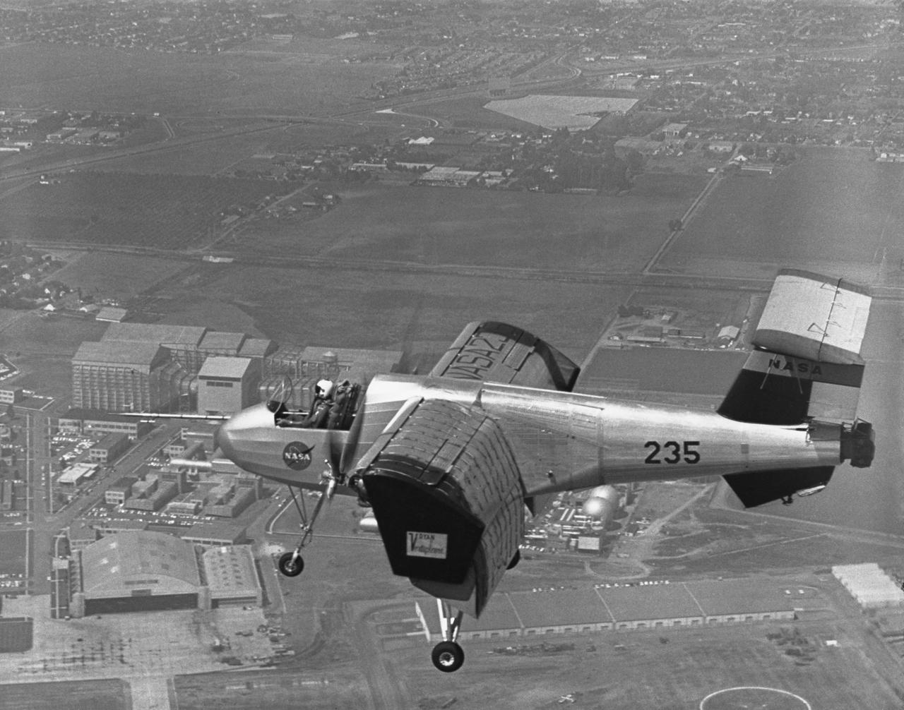
Ryan VZ-3RY over Ames in slow-speed flight. Smooth airflow over entire wing is indicated by tufts when wing had been modified to incorporate leading-edge slats. Tests showed that it could be flown at speeds as low as 6 knots when out of ground effect (which increases lift). April 1963 published in NASA SP-2002-4525 Memoirs of a Flight test Engineer (Seth Anderson)
NASA's Stratospheric Observatory for Infrared Astronomy, or SOFIA, arrived at NASA's Dryden Flight Research Center at Edwards Air Force Base, Calif. on May 31, 2007. The heavily modified Boeing 747SP was ferried to Dryden from Waco, Texas, where L-3 Communications Integrated Systems installed a German-built 2.5-meter infrared telescope and made other major modifications over the past several years. SOFIA is scheduled to undergo installation and integration of mission systems and a multi-phase flight test program at Dryden over the next three years that is expected to lead to a full operational capability to conduct astronomy missions in about 2010. During its expected 20-year lifetime, SOFIA will be capable of "Great Observatory" class astronomical science, providing astronomers with access to the visible, infrared and sub-millimeter spectrum with optimized performance in the mid-infrared to sub-millimeter range.
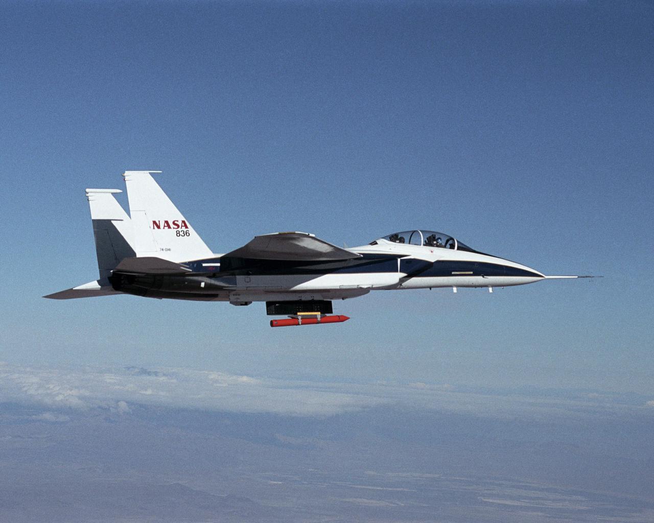
NASA Dryden's new in-house designed Propulsion Flight Test Fixture (PFTF) flew mated to a specially-equipped supersonic F-15B research aircraft during December 2001 and January 2002.
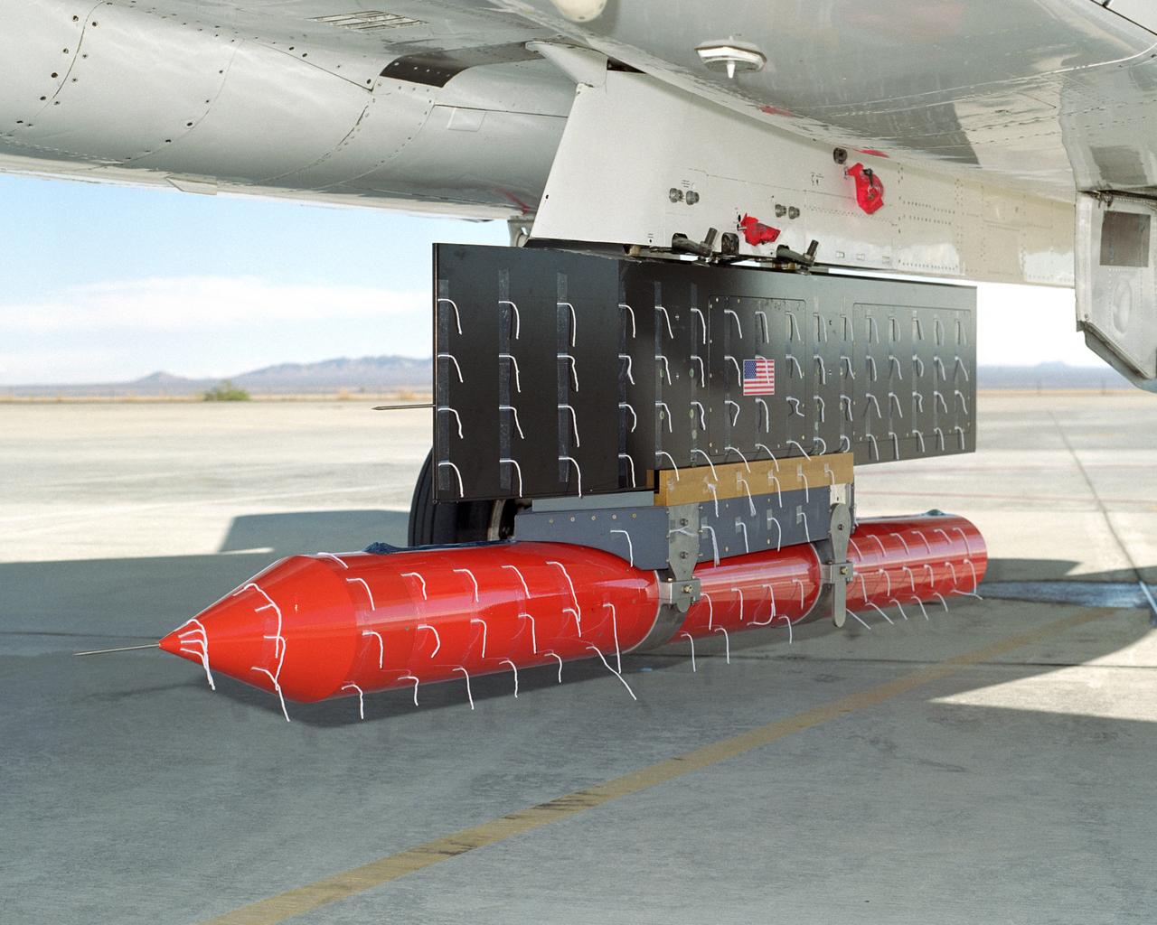
NASA Dryden's new in-house designed Propulsion Flight Test Fixture (PFTF), carried on an F-15B's centerline attachment point, underwent flight envelope expansion in order to verify its design and capabilities.
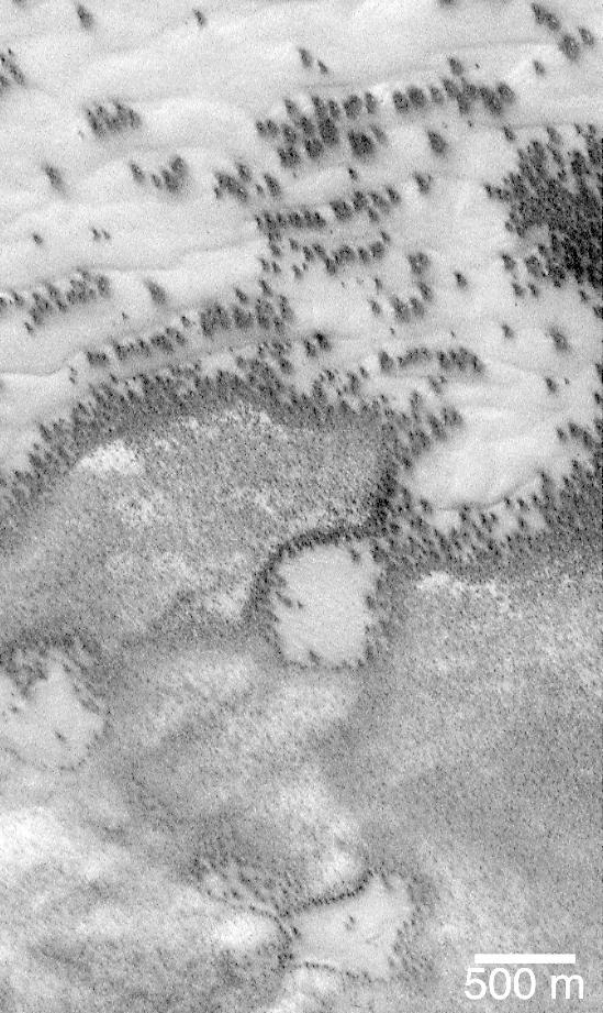
"They look like bushes!" That's what almost everyone says when they see the dark features found in pictures taken of sand dunes in the polar regions as they are beginning to defrost after a long, cold winter. It is hard to escape the fact that, at first glance, these images acquired by the Mars Global Surveyor (MGS) Mars Orbiter Camera (MOC) over both polar regions during the spring and summer seasons, do indeed resemble aerial photographs of sand dune fields on Earth -- complete with vegetation growing on and around them! Of course, this is not what the features are, as we describe below and in related picture captions. Still, don't they look like vegetation to you? Shown here are two views of the same MGS MOC image. On the left is the full scene, on the right is an expanded view of a portion of the scene on the left. The bright, smooth surfaces that are dotted with occasional, nearly triangular dark spots are sand dunes covered by winter frost. The MGS MOC has been used over the past several months (April-August 1999) to monitor dark spots as they form and evolve on polar dune surfaces. The dark spots typically appear first along the lower margins of a dune -- similar to the position of bushes and tufts of grass that occur in and among some sand dunes on Earth. Because the martian air pressure is very low -- 100 times lower than at Sea Level on Earth -- ice on Mars does not melt and become liquid when it warms up. Instead, ice sublimes -- that is, it changes directly from solid to gas, just as "dry ice" does on Earth. As polar dunes emerge from the months-long winter night, and first become exposed to sunlight, the bright winter frost and snow begins to sublime. This process is not uniform everywhere on a dune, but begins in small spots and then over several months it spreads until the entire dune is spotted like a leopard. The early stages of the defrosting process -- as in the picture shown here -- give the impression that something is "growing" on the dunes. The sand underneath the frost is dark, just like basalt beach sand in Hawaii. Once it is exposed to sunlight, the dark sand probably absorbs sunlight and helps speed the defrosting of each sand dune. This picture was taken by MGS MOC on July 21, 1999. The dunes are located in the south polar region and are expected to be completely defrosted by November or December 1999. North is approximately up, and sunlight illuminates the scene from the upper left. The 500 meter scale bar equals 547 yards; the 300 meter scale is also 328 yards. http://photojournal.jpl.nasa.gov/catalog/PIA02300