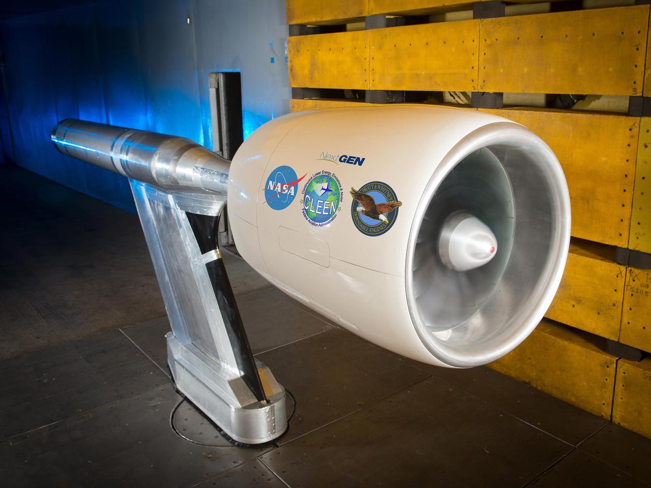
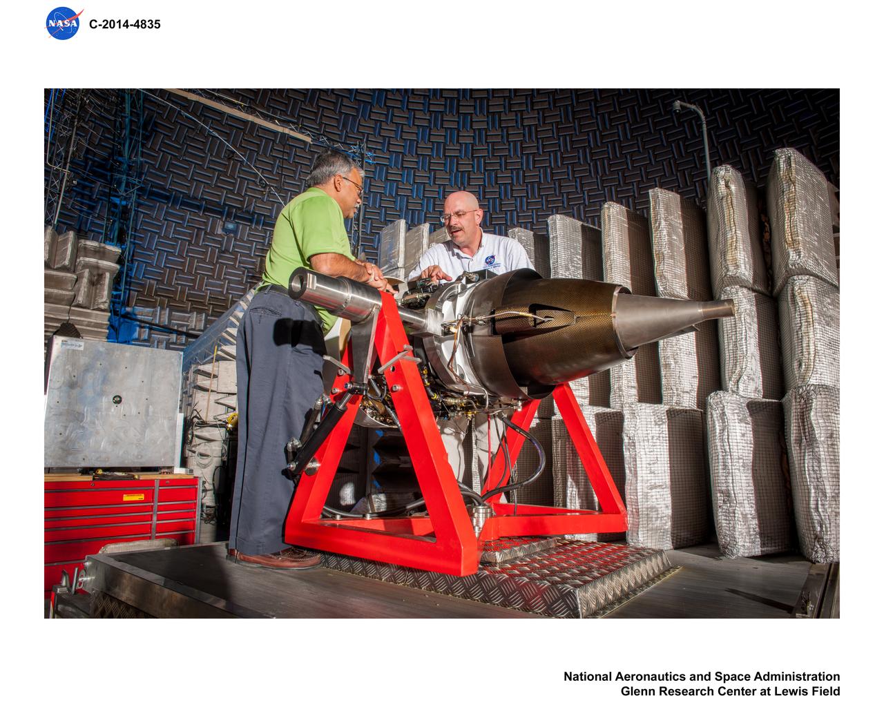
NASA’s Environmentally Responsible Aviation Project, in collaboration with the Federal Aviation Administration (FAA) and Pratt & Whitney, completed testing of an Ultra High Bypass Ratio Turbofan Model in the 9’ x 15’ Low Speed Wind Tunnel at NASA Glenn Research Center. The fan model is representative of the next generation of efficient and quiet Ultra High Bypass Ratio Turbofan Engine designs.
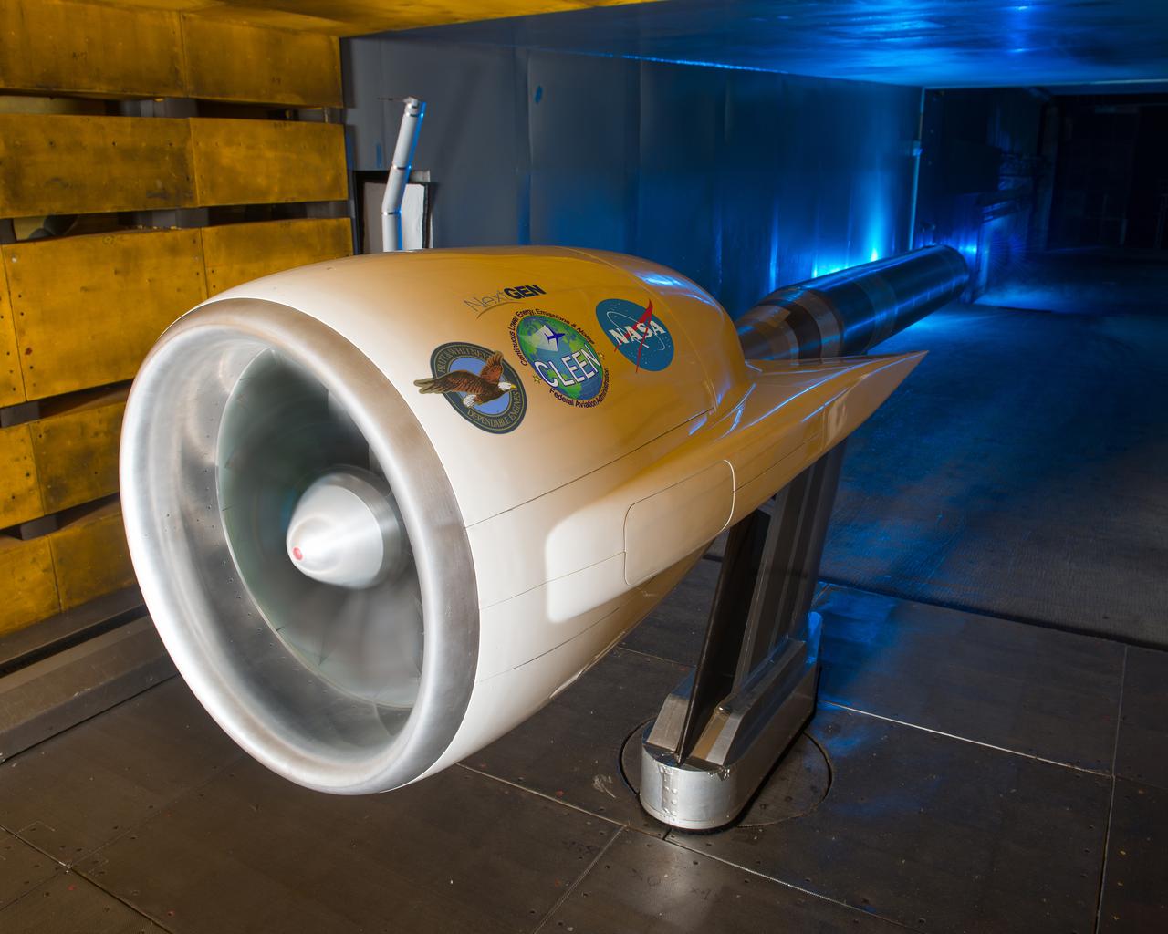
Ultra High Bypass Integrated System Test Testing of an Ultra High Bypass Ratio Turbofan model in the 9-by 15-Foot Low Speed Wind Tunnel. Pratt & Whitney designed the experimental engine to meet new efficiency and noise reduction targets for commercial aircraft set by NASA and the Federal Aviation Administration. The 9-by 15 tests analyzed two noise reduction technologies.
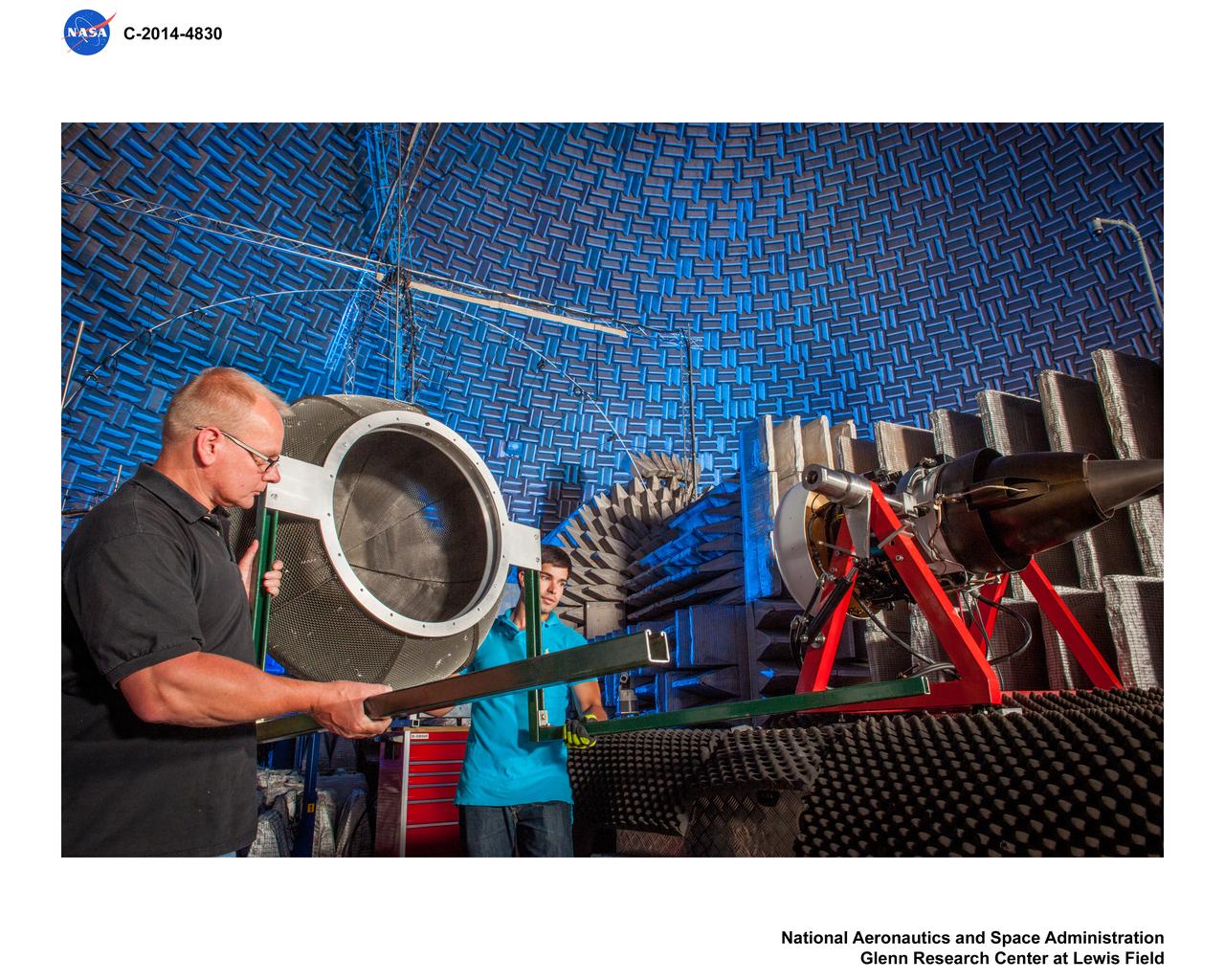
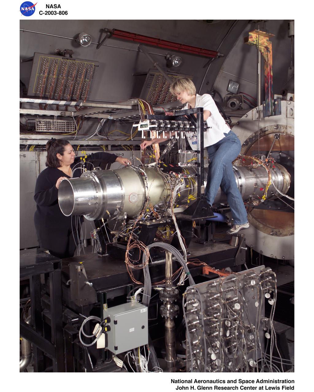
Truck Mounted Turbofan Engine in Aero Acoustic Propulsion Laboratory, AAPL, Facility
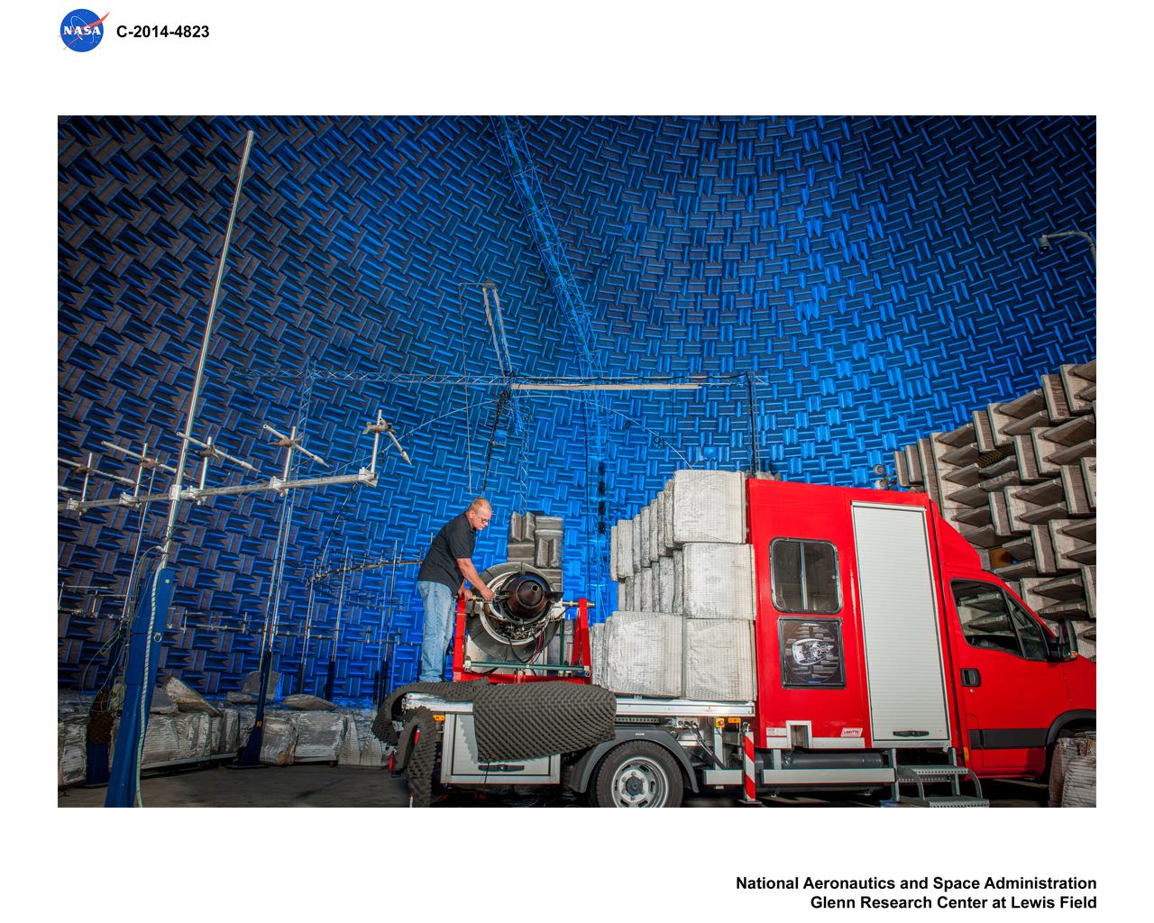
Truck Mounted Turbofan Engine in Aero Acoustic Propulsion Laboratory, AAPL, Facility
Truck Mounted Turbofan Engine in Aero Acoustic Propulsion Laboratory, AAPL, Facility
WILLIAMS INTERNATIONAL FJ33 TURBOFAN JET ENGINE TEST IN THE PROPULSION SYSTEMS LAB - PSL - CELL 4
Next-Generation Aircraft, Pratt and Whitney Ultra-High Bypass Integration test at NASA Ames 11ft. wind tunnel (test 11-0182) assess the interaction effects of a scaled Pratt & Whitney geared turbofan on a Boeing 737-800 fuselage in an effort to use emerging technologies to make next-generation airliners quieter, more fuel efficient and lower on emissions. (printed in Aviation Week & Space Technology April 8, 2011 issue)
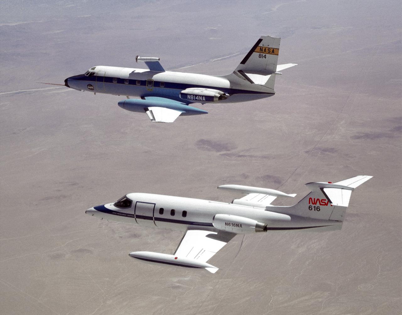
The NASA C-140 JetStar research aircraft (top) is followed by a NASA Learjet equipped with acoustic sensors during one of several tests of advanced propellors mounted on the vertical pylon atop the JetStar's fuselage. Several advanced prop designs were tested on the JetStar in 1982 by NASA's Dryden Flight Research Facility (DFRF), Edwards, California, to study the effects of noise created by propellors on aircraft structures and cabin interiors. To assess possible noise problems with the subscale turbofan, DFRF technicians mounted microphones on both the JetStar and the Learjet chase plane. DFRF then made measurements at close range and at longer distances. The data enabled structural changes and flightpath modifications.
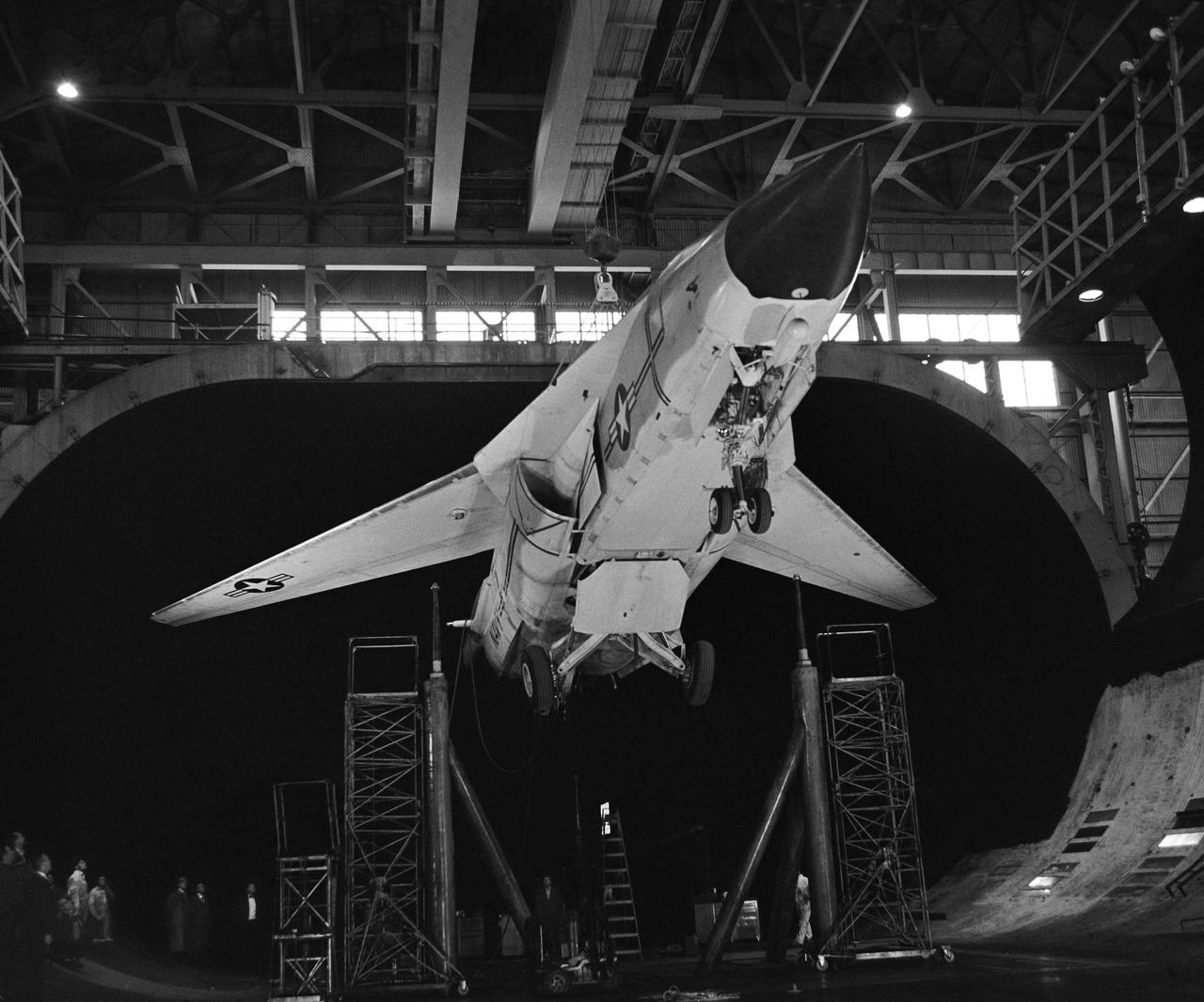
Installation Photos, 3/4 front view from below. F-111B in Ames 40x80 Foot Wind Tunnel. The General Dynamics/Grumman F-111B was a long-range carrier-based interceptor aircraft that was planned to be a follow-on to the F-4 Phantom II. The F-111B was developed in the 1960s by General Dynamics in conjunction with Grumman for the United States Navy (USN) as part of the joint Tactical Fighter Experimental (TFX) with the United States Air Force (USAF) to produce a common fighter for the services that could perform a variety of missions. It incorporated innovations such as variable-geometry wings, afterburning turbofan engines, and a long-range radar and missile weapons system.
The Fan Noise Test Facility built at the Lewis Research Center to obtain far-field noise data for the National Aeronautics and Space Administration (NASA) and General Electric Quiet Engine Program. The engine incorporated existing noise reduction methods into an engine of similar power to those that propelled the Boeing 707 or McDonnell-Douglas DC-8 airliner. The new the low-bypass ratio turbofan engines of the 1960s were inherently quieter than their turbojet counterparts, researchers had a better grasp of the noise generation problem, and new acoustic technologies had emerged. Lewis contracted General Electric in 1969 to build and aerodynamically test three experimental engines with 72-inch diameter fans. The engines were then brought to Lewis and tested with an acoustically treated nacelle. This Fan Noise Test Facility was built off of the 10- by 10-Foot Supersonic Wind Tunnel’s Main Compressor and Drive Building. Lewis researchers were able to isolate the fan’s noise during these initial tests by removing the core of the engine. The Lewis test rig drove engines to takeoff tip speeds of 1160 feet per second. The facility was later used to test a series of full-scale model fans and fan noise suppressors to be used with the quiet engine. NASA researchers predicted low-speed single-stage fans without inlet guide vanes and with large spacing between rotors and stators would be quieter. General Electric modified a TF39 turbofan engine by removing the the outer protion of the fan and spacing the blade rows of the inner portion. The tests revealed that the untreated version of the engine generated less noise than was anticipated, and the acoustically treated nacelle substantially reduced engine noise.
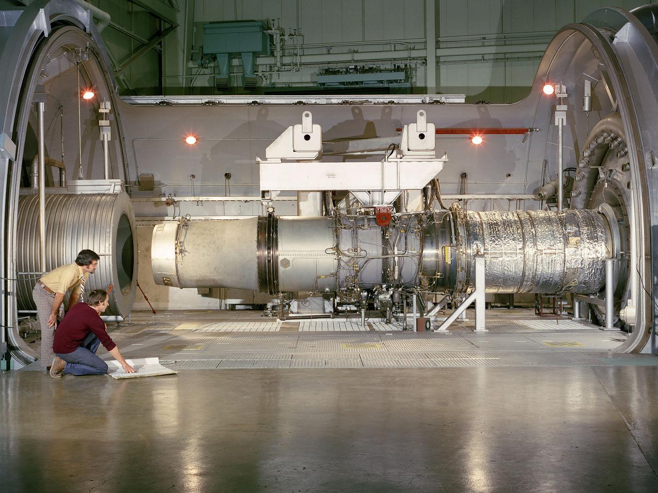
A refanned Pratt and Whitney JT-8D-109 turbofan engine installed in Cell 4 of the Propulsion Systems Laboratory at the National Aeronautics and Space Administration (NASA) Lewis Research Center. NASA Lewis’ Refan Program sought to demonstrate that noise reduction modifications could be applied to existing aircraft engines with minimal costs and without diminishing the engine’s performance or integrity. At the time, Pratt and Whitney’s JT-8D turbofans were one of the most widely used engines in the commercial airline industry. The engines powered Boeing’s 727 and 737 and McDonnell Douglas’ DC-9 aircraft. Pratt and Whitney worked with the airline manufacturers on a preliminary study that verified feasibility of replacing the JT-8D’s two-stage fan with a larger single-stage fan. The new fan slowed the engine’s exhaust, which significantly reduced the amount of noise it generated. Booster stages were added to maintain the proper level of airflow through the engine. Pratt and Whitney produced six of the modified engines, designated JT-8D-109, and performed the initial testing. One of the JT-8D-109 engines, seen here, was tested in simulated altitude conditions in NASA Lewis’ Propulsion Systems Laboratory. The Refan engine was ground-tested on an actual aircraft before making a series of flight tests on 727 and DC-9 aircraft in early 1976. The Refan Program reduced the JT-8D’s noise by 50 percent while increasing the fuel efficiency. The retro-fit kits were estimated to cost between $1 million and $1.7 million per aircraft.
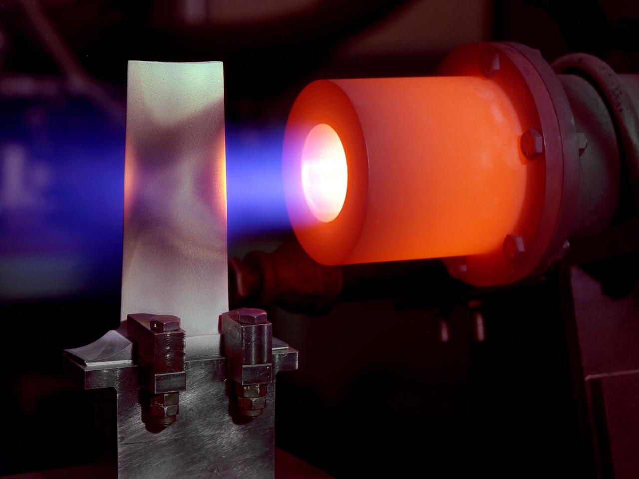
A 1-foot long stator blade with a thermal coating subjected to intense heat in order to test its strength at the National Aeronautics and Space Administration (NASA) Lewis Research Center. Lewis researchers sought to determine optimal types of ceramic coatings to increase the durability of metals. The research was primarily intended to support the design of stator blades for high-performance axial-flow compressor and turbofan engines. The coatings reduced the temperature of the metal and the amount of required cooling. As engines became more and more sophisticated, compressor blades were required to withstand higher and higher temperatures. Lewis researchers developed a dual-layer thermal-barrier coating that could be applied to turbine vanes and blades and combustion liners. This new sprayable thermal-barrier coating was evaluated for its durability, strength, fatigue, and aerodynamic penalties. This hot-gas rig fired the scorching gas at the leading edge of a test blade. The blade was cooled by an internal air flow. The blades were heated at two different velocities during the program. When using Mach 0.3 gases the entire heating and cooling cycle only lasted 30 seconds. The cycle lasted 60 minutes during tests at Mach 1.
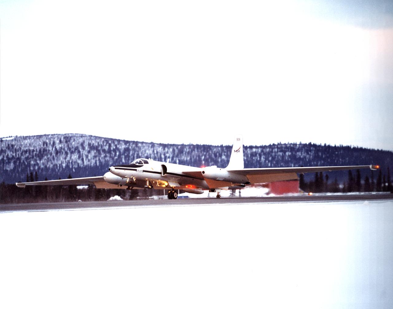
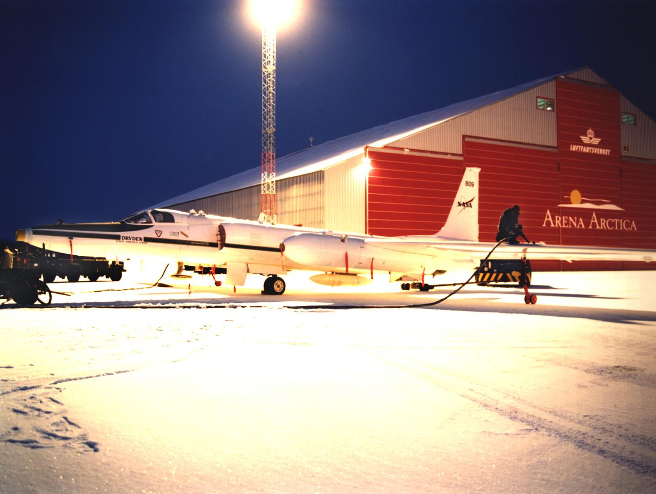
ER-2s bearing tail numbers 806 and 809 are used as airborne science platforms by NASA's Dryden Flight Research Center. The aircraft are platforms for a variety of high-altitude science missions flown over various parts of the world. They are also used for earth science and atmospheric sensor research and development, satellite calibration and data validation. The ER-2s are capable of carrying a maximum payload of 2,600 pounds of experiments in a nose bay, the main equipment bay behind the cockpit, two wing-mounted superpods and small underbody and trailing edges. Most ER-2 missions last about six hours with ranges of about 2,200 nautical miles. The aircraft typically fly at altitudes above 65,000 feet. On November 19, 1998, an ER-2 set a world record for medium weight aircraft reaching an altitude of 68,700 feet. The aircraft is 63 feet long, with a wingspan of 104 feet. The top of the vertical tail is 16 feet above ground when the aircraft is on the bicycle-type landing gear. Cruising speeds are 410 knots, or 467 miles per hour, at altitude. A single General Electric F-118 turbofan engine rated at 17,000 pounds thrust powers the ER-2.

ER-2s bearing tail numbers 806 and 809 are used as airborne science platforms by NASA's Dryden Flight Research Center. The aircraft are platforms for a variety of high-altitude science missions flown over various parts of the world. They are also used for earth science and atmospheric sensor research and development, satellite calibration and data validation. The ER-2s are capable of carrying a maximum payload of 2,600 pounds of experiments in a nose bay, the main equipment bay behind the cockpit, two wing-mounted superpods and small underbody and trailing edges. Most ER-2 missions last about six hours with ranges of about 2,200 nautical miles. The aircraft typically fly at altitudes above 65,000 feet. On November 19, 1998, an ER-2 set a world record for medium weight aircraft reaching an altitude of 68,700 feet. The aircraft is 63 feet long, with a wingspan of 104 feet. The top of the vertical tail is 16 feet above ground when the aircraft is on the bicycle-type landing gear. Cruising speeds are 410 knots, or 467 miles per hour, at altitude. A single General Electric F-118 turbofan engine rated at 17,000 pounds thrust powers the ER-2.
A researcher examines an Advanced Technology Transport model installed in the 8- by 6-Foot Supersonic Wind Tunnel at the National Aeronautics and Space Administration (NASA) Lewis Research Center. The Advanced Technology Transport concept was a 200-person supersonic transport aircraft that could cruise at Mach 0.9 to 0.98 with low noise and pollution outputs. General Electric and Pratt and Whitney responded to NASA Lewis’ call to design a propulsion system for the aircraft. The integration of the propulsion system with the airframe was one of the greatest challenges facing the designers of supersonic aircraft. The aircraft’s flow patterns and engine nacelles could significantly affect the performance of the engines. NASA Lewis researchers undertook a study of this 0.30-scale model of the Advanced Technology Transport in the 8- by 6-foot tunnel. The flow-through nacelles were located near the rear of the fuselage during the initial tests, seen here, and then moved under the wings for ensuing runs. Different engine cowl shapes were also analyzed. The researchers determined that nacelles mounted at the rear of the aircraft produced more efficient airflow patterns during cruising conditions at the desired velocities. The concept of the Advanced Technology Transport, nor any other US supersonic transport, has ever come to fruition. The energy crisis, environmental concerns, and inadequate turbofan technology of the 1970s were among the most significant reasons.
Engineer Frank Kutina and a National Aeronautics and Space Administration (NASA) mechanic examine the setup of an advanced combustor rig inside one of the test cells at the Lewis Research Center’s Four Burner Area in the Engine Research Building. Kutina, of the Research Operations Branch, served as go-between for the researchers and the mechanics. He helped develop the test configurations and get the hardware installed. At the time of this photograph, Lewis Center Director Abe Silverstein had just established the Airbreathing Engine Division to address the new propulsion of the 1960s. After nearly a decade of focusing almost exclusively on space, NASA Lewis began tackling issues relating to the new turbofan engine, noise reduction, energy efficiency, supersonic transport, and the never-ending quest for higher performance levels with smaller and more lightweight engines. The Airbreathing Engine Division’s Combustion Branch was dedicated to the study and mitigation of the high temperatures and pressures found in advanced combustor designs. These high temperatures and pressures could destroy engine components. The Lewis investigation included film cooling, diffuser flow, and jet mixing. Components were tested in smaller test cells, but a full-scale augmenting burner rig, seen here, was tested extensively in the Four Burner Area test cell.
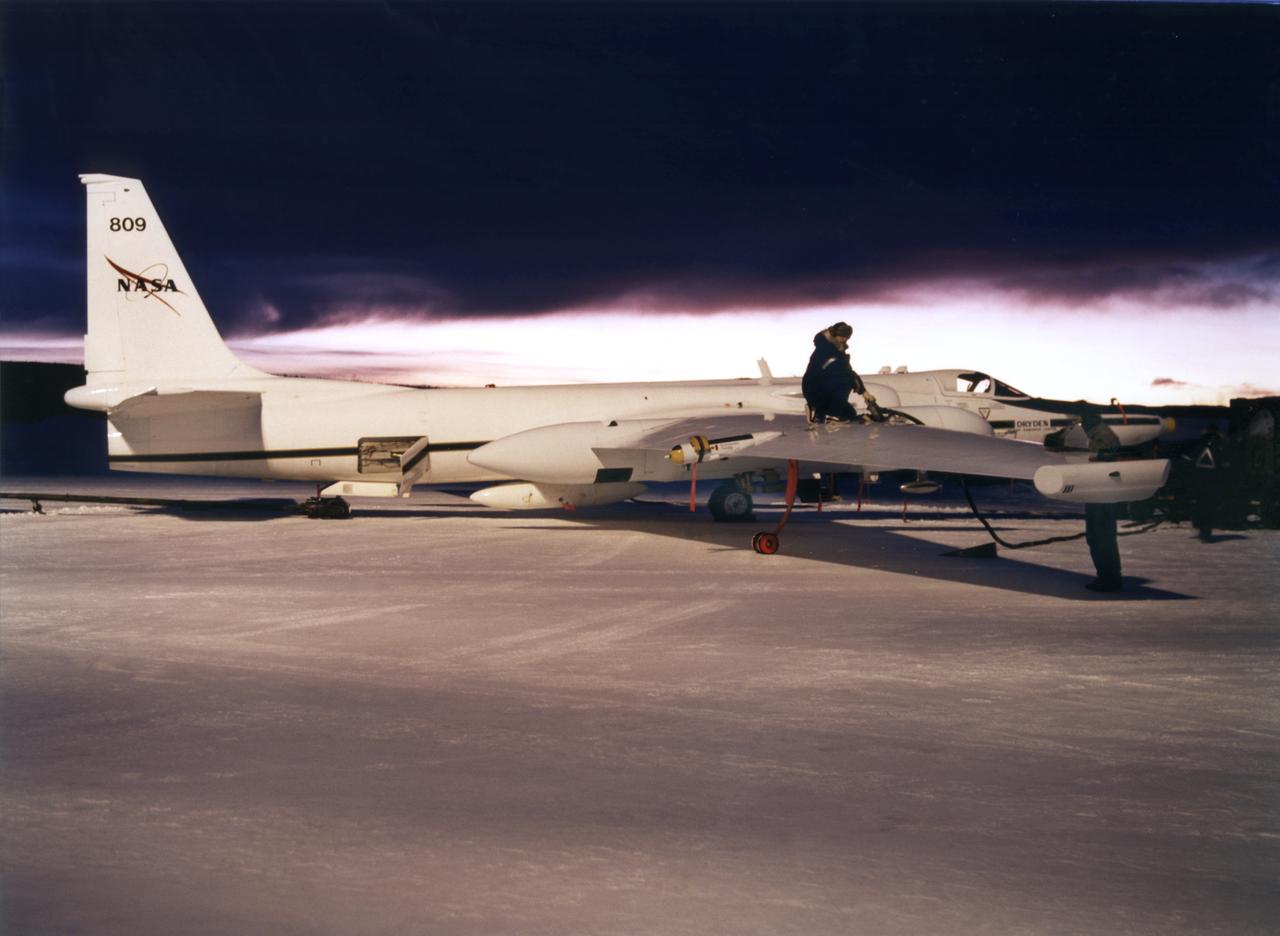
ER-2s bearing tail numbers 806 and 809 are used as airborne science platforms by NASA's Dryden Flight Research Center. The aircraft are platforms for a variety of high-altitude science missions flown over various parts of the world. They are also used for earth science and atmospheric sensor research and development, satellite calibration and data validation. The ER-2s are capable of carrying a maximum payload of 2,600 pounds of experiments in a nose bay, the main equipment bay behind the cockpit, two wing-mounted superpods and small underbody and trailing edges. Most ER-2 missions last about six hours with ranges of about 2,200 nautical miles. The aircraft typically fly at altitudes above 65,000 feet. On November 19, 1998, an ER-2 set a world record for medium weight aircraft reaching an altitude of 68,700 feet. The aircraft is 63 feet long, with a wingspan of 104 feet. The top of the vertical tail is 16 feet above ground when the aircraft is on the bicycle-type landing gear. Cruising speeds are 410 knots, or 467 miles per hour, at altitude. A single General Electric F-118 turbofan engine rated at 17,000 pounds thrust powers the ER-2.

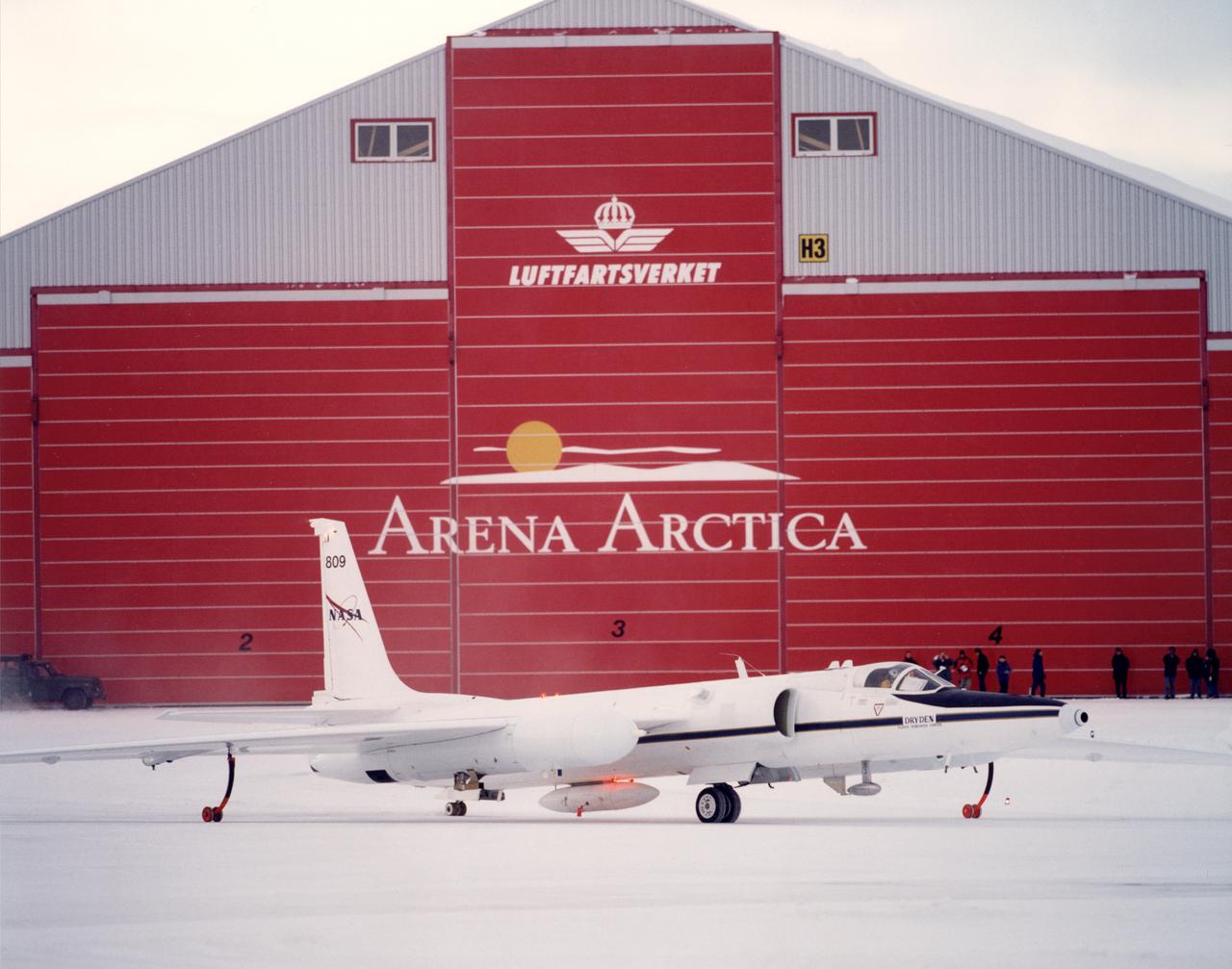
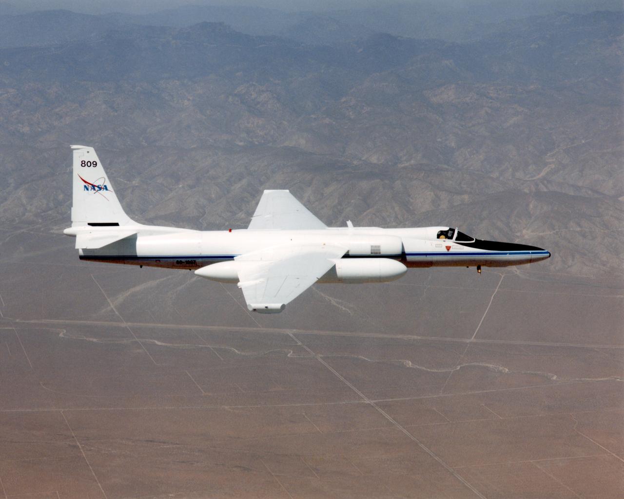
ER-2 tail number 809, is one of two Airborne Science ER-2s used as science platforms by Dryden. The aircraft are platforms for a variety of high-altitude science missions flown over various parts of the world. They are also used for earth science and atmospheric sensor research and development, satellite calibration and data validation. The ER-2s are capable of carrying a maximum payload of 2,600 pounds of experiments in a nose bay, the main equipment bay behind the cockpit, two wing-mounted superpods and small underbody and trailing edges. Most ER-2 missions last about six hours with ranges of about 2,200 nautical miles. The aircraft typically fly at altitudes above 65,000 feet. On November 19, 1998, the ER-2 set a world record for medium weight aircraft reaching an altitude of 68,700 feet. The aircraft is 63 feet long, with a wingspan of 104 feet. The top of the vertical tail is 16 feet above ground when the aircraft is on the bicycle-type landing gear. Cruising speeds are 410 knots, or 467 miles per hour, at altitude. A single General Electric F118 turbofan engine rated at 17,000 pounds thrust powers the ER-2.

ER-2 tail number 806, is one of two Airborne Science ER-2s used as science platforms by Dryden. The aircraft are platforms for a variety of high-altitude science missions flown over various parts of the world. They are also used for earth science and atmospheric sensor research and development, satellite calibration and data validation. The ER-2s are capable of carrying a maximum payload of 2,600 pounds of experiments in a nose bay, the main equipment bay behind the cockpit, two wing-mounted superpods and small underbody and trailing edges. Most ER-2 missions last about six hours with ranges of about 2,200 nautical miles. The aircraft typically fly at altitudes above 65,000 feet. On November 19, 1998, the ER-2 set a world record for medium weight aircraft reaching an altitude of 68,700 feet. The aircraft is 63 feet long, with a wingspan of 104 feet. The top of the vertical tail is 16 feet above ground when the aircraft is on the bicycle-type landing gear. Cruising speeds are 410 knots, or 467 miles per hour, at altitude. A single General Electric F-118 turbofan engine rated at 17,000 pounds thrust powers the ER-2.

ER-2 tail number 806, is one of two Airborne Science ER-2s used as science platforms by Dryden. The aircraft are platforms for a variety of high-altitude science missions flown over various parts of the world. They are also used for earth science and atmospheric sensor research and development, satellite calibration and data validation. The ER-2s are capable of carrying a maximum payload of 2,600 pounds of experiments in a nose bay, the main equipment bay behind the cockpit, two wing-mounted superpods and small underbody and trailing edges. Most ER-2 missions last about six hours with ranges of about 2,200 nautical miles. The aircraft typically fly at altitudes above 65,000 feet. On November 19, 1998, the ER-2 set a world record for medium weight aircraft reaching an altitude of 68,700 feet. The aircraft is 63 feet long, with a wingspan of 104 feet. The top of the vertical tail is 16 feet above ground when the aircraft is on the bicycle-type landing gear. Cruising speeds are 410 knots, or 467 miles per hour, at altitude. A single General Electric F-118 turbofan engine rated at 17,000 pounds thrust powers the ER-2.
ER-2s bearing tail numbers 806 and 809 are used as airborne science platforms by NASA's Dryden Flight Research Center. The aircraft are platforms for a variety of high-altitude science missions flown over various parts of the world. They are also used for earth science and atmospheric sensor research and development, satellite calibration and data validation. The ER-2s are capable of carrying a maximum payload of 2,600 pounds of experiments in a nose bay, the main equipment bay behind the cockpit, two wing-mounted superpods and small underbody and trailing edges. Most ER-2 missions last about six hours with ranges of about 2,200 nautical miles. The aircraft typically fly at altitudes above 65,000 feet. On November 19, 1998, an ER-2 set a world record for medium weight aircraft reaching an altitude of 68,700 feet. The aircraft is 63 feet long, with a wingspan of 104 feet. The top of the vertical tail is 16 feet above ground when the aircraft is on the bicycle-type landing gear. Cruising speeds are 410 knots, or 467 miles per hour, at altitude. A single General Electric F-118 turbofan engine rated at 17,000 pounds thrust powers the ER-2.
ER-2C tail number 809, was one of two Airborne Science ER-2Cs used as science platforms by Dryden. The aircraft were platforms for a variety of high-altitude science missions flown over various parts of the world. They were also used for earth science and atmospheric sensor research and development, satellite calibration and data validation. The ER-2Cs were capable of carrying a maximum payload of 2,600 pounds of experiments in a nose bay, the main equipment bay behind the cockpit, two wing-mounted superpods and small underbody and trailing edges. Most ER-2C missions lasted about six hours with ranges of about 2,200 nautical miles. The aircraft typically flew at altitudes above 65,000 feet. On November 19, 1998, the ER-2C set a world record for medium weight aircraft reaching an altitude of 68,700 feet. The aircraft was 63 feet long, with a wingspan of 104 feet. The top of the vertical tail was 16 feet above ground when the aircraft was on the bicycle-type landing gear. Cruising speeds were 410 knots, or 467 miles per hour, at altitude. A single General Electric F-118 turbofan engine rated at 17,000 pounds thrust powers the ER-2C.
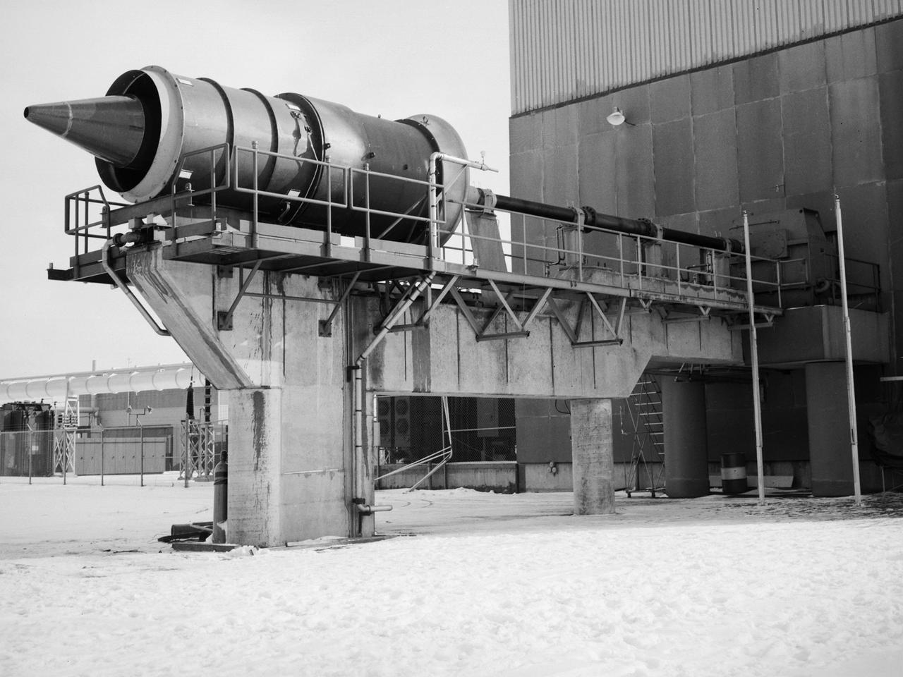
The Propulsion Systems Laboratory’s exhaust system was expanded in 1955 at the National Advisory Committee for Aeronautics (NACA) Lewis Flight Propulsion Laboratory. The facility contained two altitude chambers that were first used to study the increasingly-powerful jet engines of the early 1950s and the ramjets for missile programs such as Navaho and Bomarc. Later, the facility tested large rocket engines and a variety of turbofan engines. The exhaust system served two roles: reducing the density of the air in the test chambers to simulate high altitudes and removing the hot gases exhausted by the engines being tested. These tasks were accomplished by large Roots-Connersville exhauster equipment in the Equipment Building. The original configuration could exhaust the 3500° F gases at a rate of 100 pounds per second when the simulated altitude was 50,000 feet. In 1955, three years after operation started, a fourth line of exhausters was added. There were three centrifugal exhausters capable of supplying 166 pounds of air per second at the test chamber altitude of 50,000 feet or 384 pounds per second at 32,000 feet. These exhausters had two first-stage castings driven by a 10,000-horsepower motor; one second; one third; and one fourth-stage casting driven by a 16,500-horsepower motor. The total inlet volume of the exhausters is 1,650,000 cubic feet of gas per minute. The exhausters were continually improved and upgraded over the years.
A Martin B-57B Canberra outfitted with a noise suppressor on its right engine at the National Aeronautics and Space Administration (NASA) Lewis Research Center. The aircraft was being prepared for the October 1966 Inspection of the center. The Inspection also marked Lewis’ twentieth anniversary. Lewis researchers had been studying engine noise for almost a decade, but the problem seemed to be increasing in the mid-1960s with heavier airline traffic and larger engines. Researchers discovered early on that the majority of the noise did not emanate from the engine itself, but from the mixing of the hot exhaust gasses with the atmosphere. Attempts to reduce the turbulence using new exhaust nozzles were successful but often resulted in decreased engine performance. The researchers decided to try to lower the jet nozzle exit velocity without decreasing its thrust. The inlet mass air flow had to be increased to accomplish this. The Lewis B-57B was powered by two Wright Aeronautical J65 turbojets. Lewis engineers modified the stators on the two engines to simulate the noise levels from more-modern turbofan engines. A noise suppressor was added to only one of the two engines, seen here on the left. The engines were run one at a time at power levels similar to landing while the aircraft sat on the Lewis hangar apron. A microphone and recording equipment was setup to capture the noise levels. The engine with the suppressor produced 13 fewer decibels than the standard engine.

ER-2 tail number 806, is one of two Airborne Science ER-2s used as science platforms by Dryden. The aircraft are platforms for a variety of high-altitude science missions flown over various parts of the world. They are also used for earth science and atmospheric sensor research and development, satellite calibration and data validation. The ER-2s are capable of carrying a maximum payload of 2,600 pounds of experiments in a nose bay, the main equipment bay behind the cockpit, two wing-mounted superpods and small underbody and trailing edges. Most ER-2 missions last about six hours with ranges of about 2,200 nautical miles. The aircraft typically fly at altitudes above 65,000 feet. On November 19, 1998, the ER-2 set a world record for medium weight aircraft reaching an altitude of 68,700 feet. The aircraft is 63 feet long, with a wingspan of 104 feet. The top of the vertical tail is 16 feet above ground when the aircraft is on the bicycle-type landing gear. Cruising speeds are 410 knots, or 467 miles per hour, at altitude. A single General Electric F-118 turbofan engine rated at 17,000 pounds thrust powers the ER-2.
ER-2s bearing tail numbers 806 and 809 are used as airborne science platforms by NASA's Dryden Flight Research Center. The aircraft are platforms for a variety of high-altitude science missions flown over various parts of the world. They are also used for earth science and atmospheric sensor research and development, satellite calibration and data validation. The ER-2s are capable of carrying a maximum payload of 2,600 pounds of experiments in a nose bay, the main equipment bay behind the cockpit, two wing-mounted superpods and small underbody and trailing edges. Most ER-2 missions last about six hours with ranges of about 2,200 nautical miles. The aircraft typically fly at altitudes above 65,000 feet. On November 19, 1998, an ER-2 set a world record for medium weight aircraft reaching an altitude of 68,700 feet. The aircraft is 63 feet long, with a wingspan of 104 feet. The top of the vertical tail is 16 feet above ground when the aircraft is on the bicycle-type landing gear. Cruising speeds are 410 knots, or 467 miles per hour, at altitude. A single General Electric F-118 turbofan engine rated at 17,000 pounds thrust powers the ER-2.
A technician checks a 0.25-scale engine model of a Vought Corporation V-530 engine in the test section of the 10- by 10-Foot Supersonic Wind Tunnel at the National Aeronautics and Space Administration (NASA) Lewis Research Center. Vought created a low-drag tandem-fan Vertical/Short and Takeoff and Landing (V/STOL) engine in the mid-1970s, designated as the V-530. The first fan on the tandem-fan engine was supplied with air through a traditional subsonic inlet, seen on the lower front of the engine. The air was exhausted through the nacelle during normal flight and directed down during takeoffs. The rear fan was supplied by the oval-shaped top inlet during all phases of the flight. The second fan exhausted its air through a rear vectorable nozzle. NASA Lewis and Vought partnered in the late 1970s to collect an array of inlet and nozzle design information on the tandem fan engines for the Navy. Vought created this .25-scale model of the V-530 for extensive testing in Lewis' 10- by 10-foot tunnel. During an early series of tests, the front fan was covered, and a turbofan simulator was used to supply air to the rear fan. The researchers then analyzed the performance of only the front fan inlet. During the final series of tests, the flow from the front fan was used to supply airflow to the rear fan. The researchers studied the inlet's recovery, distortion, and angle-of-attack limits over various flight conditions.
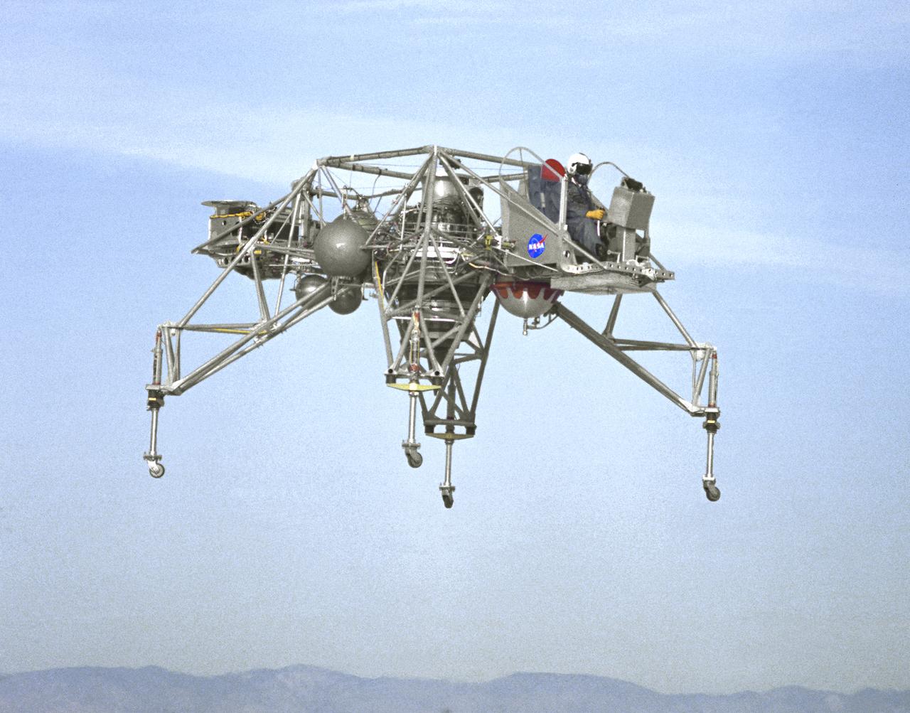
In this NASA Flight Reserch Center photograph the Lunar Landing Research Vehicle (LLRV) number 1 is shown in flight. When Apollo planning was underway in 1960, NASA was looking for a simulator to profile the descent to the Moon's surface. Three concepts surfaced: an electronic simulator, a tethered device, and the ambitious Dryden contribution, a free-flying vehicle. All three became serious projects, but eventually the NASA Flight Research Center's (FRC) Landing Research Vehicle (LLRV) became the most significant one. Hubert M. Drake is credited with originating the idea, while Donald Bellman and Gene Matranga were senior engineers on the project, with Bellman, the project manager. Simultaneously, and independently, Bell Aerosystems Company, Buffalo, N.Y., a company with experience in vertical takeoff and landing (VTOL) aircraft, had conceived a similar free-flying simulator and proposed their concept to NASA headquarters. NASA Headquarters put FRC and Bell together to collaborate. The challenge was; to allow a pilot to make a vertical landing on Earth in a simulated Moon environment, one sixth of the Earth's gravity and with totally transparent aerodynamic forces in a "free flight" vehicle with no tether forces acting on it. Built of tubular aluminum like a giant four-legged bedstead, the vehicle was to simulate a lunar landing profile from around 1500 feet to the Moon's surface. To do this, the LLRV had a General Electric CF-700-2V turbofan engine mounted vertically in gimbals, with 4200 pounds of thrust. The engine, using JP-4 fuel, got the vehicle up to the test altitude and was then throttled back to support five-sixths of the vehicle's weight, simulating the reduced gravity of the Moon. Two hydrogen-peroxide lift rockets with thrust that could be varied from 100 to 500 pounds handled the LLRV's rate of descent and horizontal translations. Sixteen smaller hydrogen-peroxide rockets, mounted in pairs, gave the pilot control in pitch, yaw, and roll. On the LLRV,
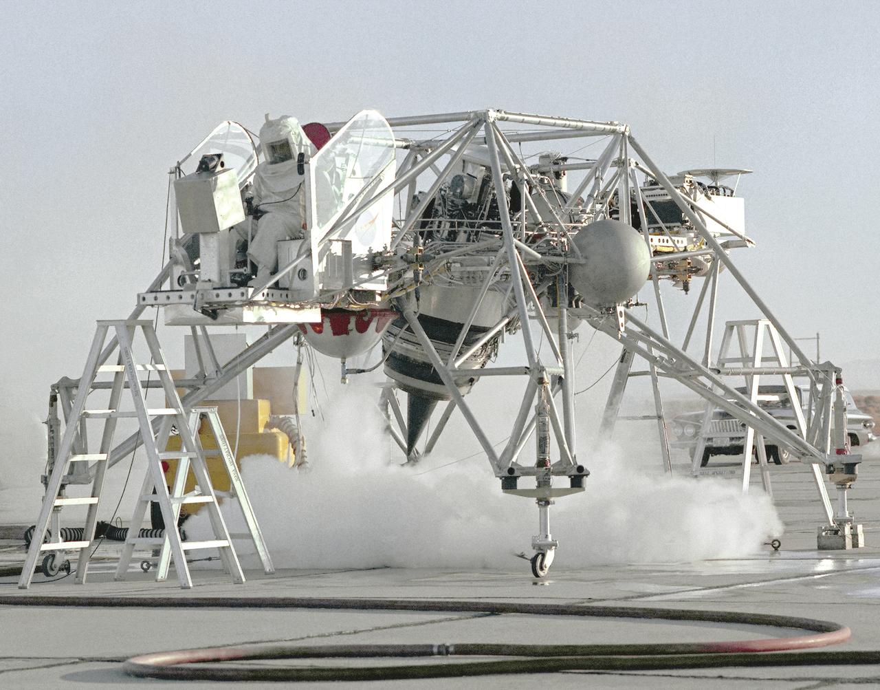
This 1964 NASA Flight Reserch Center photograph shows a ground engine test underway on the Lunar Landing Research Vehicle (LLRV) number 1. When Apollo planning was underway in 1960, NASA was looking for a simulator to profile the descent to the Moon's surface. Three concepts surfaced: an electronic simulator, a tethered device, and the ambitious Dryden contribution, a free-flying vehicle. All three became serious projects, but eventually the NASA Flight Research Center's (FRC) Landing Research Vehicle (LLRV) became the most significant one. Hubert M. Drake is credited with originating the idea, while Donald Bellman and Gene Matranga were senior engineers on the project, with Bellman, the project manager. Simultaneously, and independently, Bell Aerosystems Company, Buffalo, N.Y., a company with experience in vertical takeoff and landing (VTOL) aircraft, had conceived a similar free-flying simulator and proposed their concept to NASA headquarters. NASA Headquarters put FRC and Bell together to collaborate. The challenge was; to allow a pilot to make a vertical landing on Earth in a simulated Moon environment, one sixth of the Earth's gravity and with totally transparent aerodynamic forces in a "free flight" vehicle with no tether forces acting on it. Built of tubular aluminum like a giant four-legged bedstead, the vehicle was to simulate a lunar landing profile from around 1500 feet to the Moon's surface. To do this, the LLRV had a General Electric CF-700-2V turbofan engine mounted vertically in gimbals, with 4200 pounds of thrust. The engine, using JP-4 fuel, got the vehicle up to the test altitude and was then throttled back to support five-sixths of the vehicle's weight, simulating the reduced gravity of the Moon. Two hydrogen-peroxide lift rockets with thrust that could be varied from 100 to 500 pounds handled the LLRV's rate of descent and horizontal translations. Sixteen smaller hydrogen-peroxide rockets, mounted in pairs, gave the pilot control in pitch, yaw,
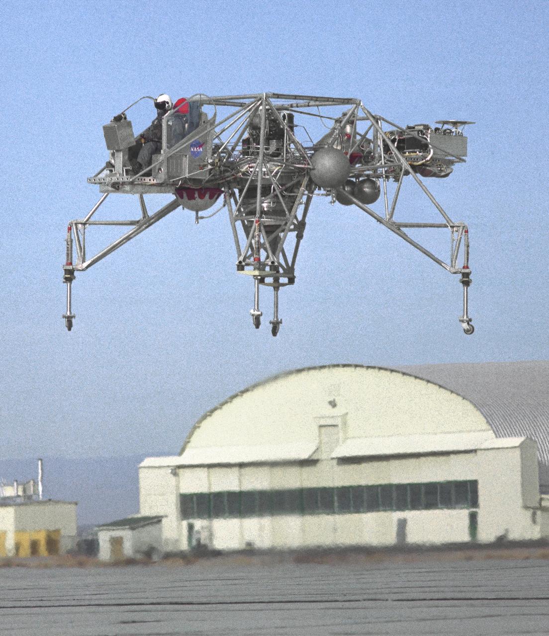
An inflight view from the left side of the Lunar Landing Research Vehicle, is shown in this 1964 NASA Flight Research Center photograph. The photograph was taken in front of the old NACA hangar located at the South Base, Edwards Air Force Base. When Apollo planning was underway in 1960, NASA was looking for a simulator to profile the descent to the Moon's surface. Three concepts surfaced: an electronic simulator, a tethered device, and the ambitious Dryden contribution, a free-flying vehicle. All three became serious projects, but eventually the NASA Flight Research Center's (FRC) Landing Research Vehicle (LLRV) became the most significant one. Hubert M. Drake is credited with originating the idea, while Donald Bellman and Gene Matranga were senior engineers on the project, with Bellman, the project manager. Simultaneously, and independently, Bell Aerosystems Company, Buffalo, N.Y., a company with experience in vertical takeoff and landing (VTOL) aircraft, had conceived a similar free-flying simulator and proposed their concept to NASA headquarters. NASA Headquarters put FRC and Bell together to collaborate. The challenge was; to allow a pilot to make a vertical landing on earth in a simulated Moon environment, one sixth of the earth's gravity and with totally transparent aerodynamic forces in a "free flight" vehicle with no tether forces acting on it. Built of tubular aluminum like a giant four-legged bedstead, the vehicle was to simulate a lunar landing profile from around 1500 feet to the Moon's surface. To do this, the LLRV had a General Electric CF-700-2V turbofan engine mounted vertically in gimbals, with 4200 pounds of thrust. The engine, using JP-4 fuel, got the vehicle up to the test altitude and was then throttled back to support five-sixths of the vehicle's weight, simulating the reduced gravity of the Moon. Two hydrogen-peroxide lift rockets with thrust that could be varied from 100 to 500 pounds handled the LLRV's rate of descent and horizontal transla
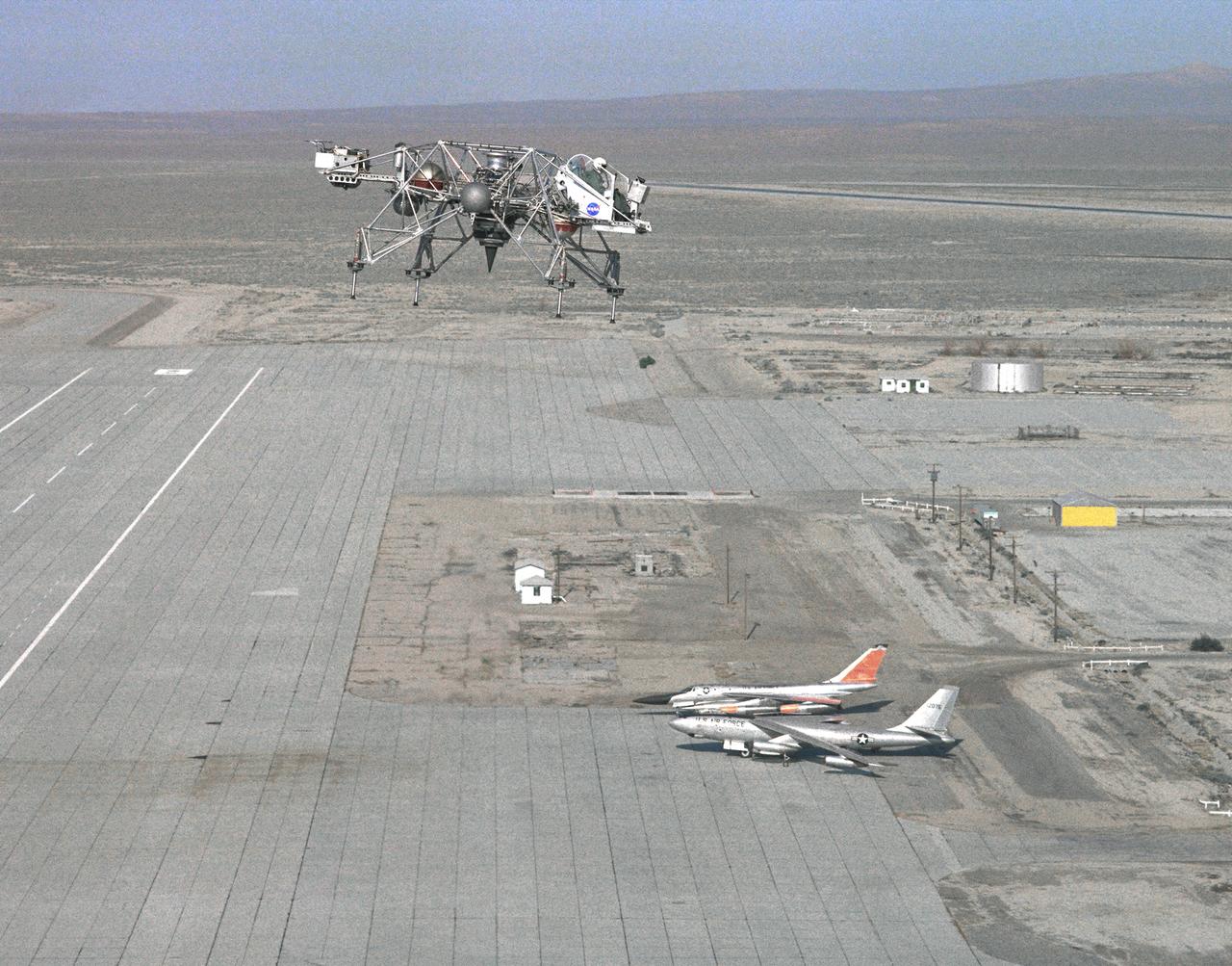
In this 1965 NASA Flight Reserch Center photograph the Lunar Landing Research Vehicle (LLRV) is shown at near maximum altitude over the south base at Edwards Air Force Base. When Apollo planning was underway in 1960, NASA was looking for a simulator to profile the descent to the moon's surface. Three concepts surfaced: an electronic simulator, a tethered device, and the ambitious Dryden contribution, a free-flying vehicle. All three became serious projects, but eventually the NASA Flight Research Center's (FRC) Landing Research Vehicle (LLRV) became the most significant one. Hubert M. Drake is credited with originating the idea, while Donald Bellman and Gene Matranga were senior engineers on the project, with Bellman, the project manager. Simultaneously, and independently, Bell Aerosystems Company, Buffalo, N.Y., a company with experience in vertical takeoff and landing (VTOL) aircraft, had conceived a similar free-flying simulator and proposed their concept to NASA headquarters. NASA Headquarters put FRC and Bell together to collaborate. The challenge was; to allow a pilot to make a vertical landing on Earth in a simulated moon environment, one sixth of the Earth's gravity and with totally transparent aerodynamic forces in a "free flight" vehicle with no tether forces acting on it. Built of tubular aluminum like a giant four-legged bedstead, the vehicle was to simulate a lunar landing profile from around 1500 feet to the moon's surface. To do this, the LLRV had a General Electric CF-700-2V turbofan engine mounted vertically in gimbals, with 4200 pounds of thrust. The engine, using JP-4 fuel, got the vehicle up to the test altitude and was then throttled back to support five-sixths of the vehicle's weight, simulating the reduced gravity of the moon. Two hydrogen-peroxide lift rockets with thrust that could be varied from 100 to 500 pounds handled the LLRV's rate of descent and horizontal translations. Sixteen smaller hydrogen-peroxide rockets, mounted in pairs, gav
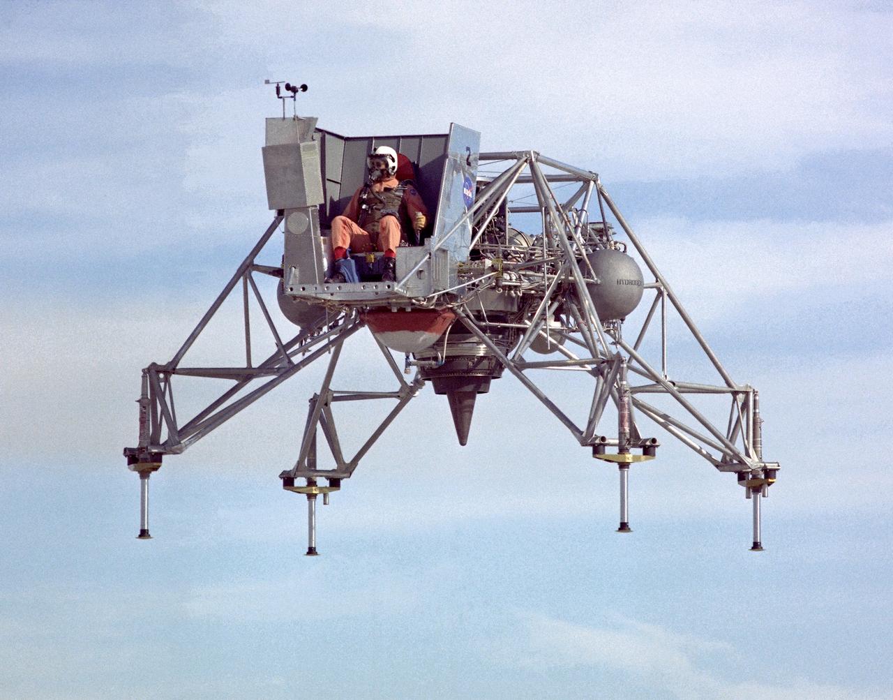
In this 1967 NASA Flight Reserch Center photograph the Lunar Landing Research Vehicle (LLRV) is viewed from the front. This photograph provideds a good view of the pilot’s platform with the restrictive cockpit view like that of he real Lunar Module (LM) When Apollo planning was underway in 1960, NASA was looking for a simulator to profile the descent to the Moon's surface. Three concepts surfaced: an electronic simulator, a tethered device, and the ambitious Dryden contribution, a free-flying vehicle. All three became serious projects, but eventually the NASA Flight Research Center’s (FRC) Lunar Landing Research Vehicle (LLRV) became the most significant one. After conceptual planning and meetings with engineers from Bell Aerosystems Company, Buffalo, N.Y., NASA FRC issued a $3.6 million production contract awarded in 1963, for delivery of the first of two vehicles for flight studies. Built of tubular aluminum alloy like a giant four-legged bedstead, the vehicle was to simulate a lunar landing profile from around 1500 feet to the Moon’s surface. The LLRV had a turbofan engine mounted vertically in a gimbal, with 4200 pounds of thrust. The engine, lifted the vehicle up to the test altitude and was then throttled back to support five-sixths of the vehicle's weight, thus simulating the reduced gravity of the Moon. Two lift rockets with thrust that could be varied from 100 to 500 pounds handled the LLRV's rate of descent and horizontal translations. Sixteen smaller rockets, mounted in pairs, gave the pilot control in pitch, yaw, and roll.. The pilot’s platform extended forward between two legs while an electronics platform, similarly located, extended rearward. The pilot had a zero-zero ejection seat that would then lift him away to safety. The two LLRVs were shipped from Bell to the FRC in April 1964, with program emphasis on vehicle No. 1. The first flight, Oct. 30, 1964, NASA research pilot Joe Walker flew it three times for a total of just under 60 seconds
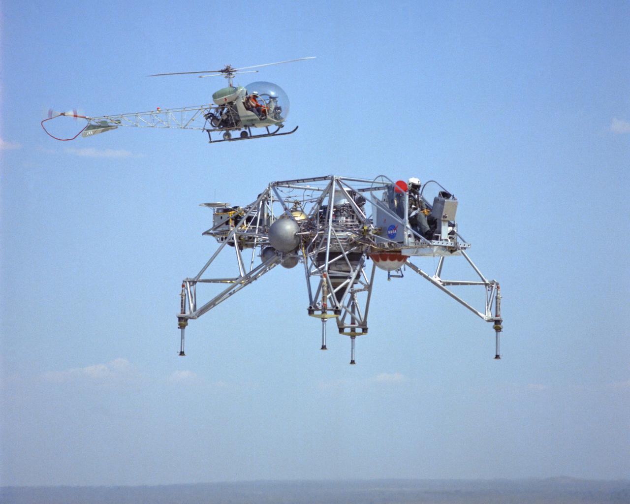
LLRV flight #1-16-61F with Bell 47 Helicopter providing chase support. The use of chase planes was a critical part of flight research well before the establishment of what was then called the NACA Muroc Flight Test Unit in September 1947 (now the NASA Dryden Flight Research Center). They act as a second set of eyes for the research pilot, warning him of any problems. When test flights of the LLRV began in October 1964, chase support for the vehicle was supplied by a Bell 47 helicopter. It could hover close by, providing information such as altitude and descent rate. LLRV test operations were phased out in late 1966 and early 1967. When Apollo planning was underway in 1960, NASA was looking for a simulator to profile the descent to the Moon's surface. Three concepts surfaced: an electronic simulator, a tethered device, and the ambitious Dryden contribution, a free-flying vehicle. All three became serious projects, but eventually the NASA Flight Research Center’s (FRC) Lunar Landing Research Vehicle (LLRV) became the most significant one. After conceptual planning and meetings with engineers from Bell Aerosystems Company, Buffalo, N.Y., NASA FRC issued a $3.6 million production contract awarded in 1963, for delivery of the first of two vehicles for flight studies. Built of tubular aluminum alloy like a giant four-legged bedstead, the vehicle was to simulate a lunar landing profile from around 1500 feet to the Moon’s surface. The LLRV had a turbofan engine mounted vertically in a gimbal, with 4200 pounds of thrust. The engine, lifted the vehicle up to the test altitude and was then throttled back to support five-sixths of the vehicle's weight, thus simulating the reduced gravity of the Moon. Two lift rockets with thrust that could be varied from 100 to 500 pounds handled the LLRV's rate of descent and horizontal translations. Sixteen smaller rockets, mounted in pairs, gave the pilot control in pitch, yaw, and roll. The pilot’s platform extended forward between t
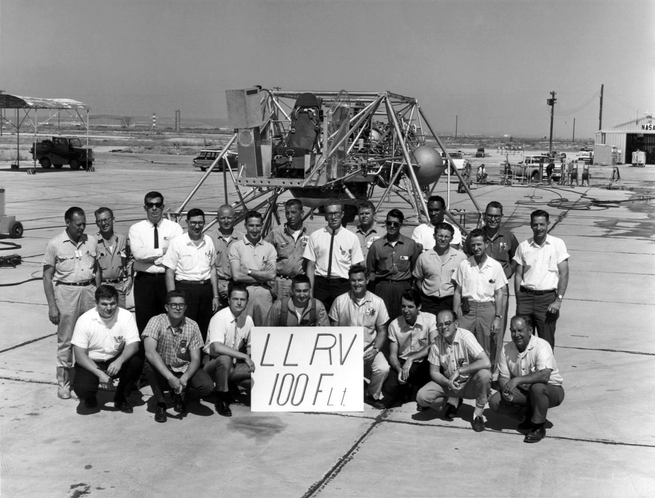
A group photo of the LLRV personnel following the program's 100th flight. The photo was taken at South Base, and was near the hangar first used by the original NACA group, at what was then called Muroc. When Apollo planning was underway in 1960, NASA was looking for a simulator to profile the descent to the moon's surface. Three concepts surfaced: an electronic simulator, a tethered device, and the ambitious Dryden contribution, a free-flying vehicle. All three became serious projects, but eventually the NASA Flight Research Center's (FRC) Landing Research Vehicle (LLRV) became the most significant one. Hubert M. Drake is credited with originating the idea, while Donald Bellman and Gene Matranga were senior engineers on the project, with Bellman, the project manager. Simultaneously, and independently, Bell Aerosystems Company, Buffalo, N.Y., a company with experience in vertical takeoff and landing (VTOL) aircraft, had conceived a similar free-flying simulator and proposed their concept to NASA headquarters. NASA Headquarters put FRC and Bell together to collaborate. The challenge was; to allow a pilot to make a vertical landing on Earth in a simulated moon environment, one sixth of the Earth's gravity and with totally transparent aerodynamic forces in a "free flight" vehicle with no tether forces acting on it. Built of tubular aluminum like a giant four-legged bedstead, the vehicle was to simulate a lunar landing profile from around 1500 feet to the moon's surface. To do this, the LLRV had a General Electric CF-700-2V turbofan engine mounted vertically in gimbals, with 4200 pounds of thrust. The engine, using JP-4 fuel, got the vehicle up to the test altitude and was then throttled back to support five-sixths of the vehicle's weight, simulating the reduced gravity of the moon. Two hydrogen-peroxide lift rockets with thrust that could be varied from 100 to 500 pounds handled the LLRV's rate of descent and horizontal translations. Sixteen smaller hydrogen-peroxide r
The unusual lines of the X-36 technology demonstrator contrast sharply with the desert floor as the remotely piloted aircraft scoots across the California desert at low altitude during a research flight on October 30, 1997.
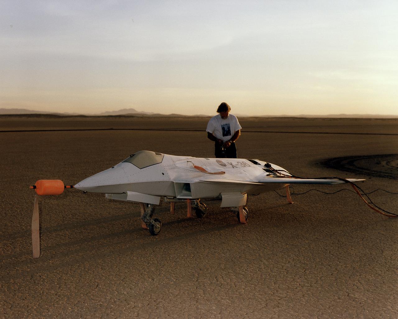
Lit by the rays of the morning sunrise on Rogers Dry Lake, adjacent to NASA's Dryden Flight Research Center, Edwards, California, a technician prepares the remotely-piloted X-36 Tailless Fighter Agility Research Aircraft for its first flight on May 17, 1997.
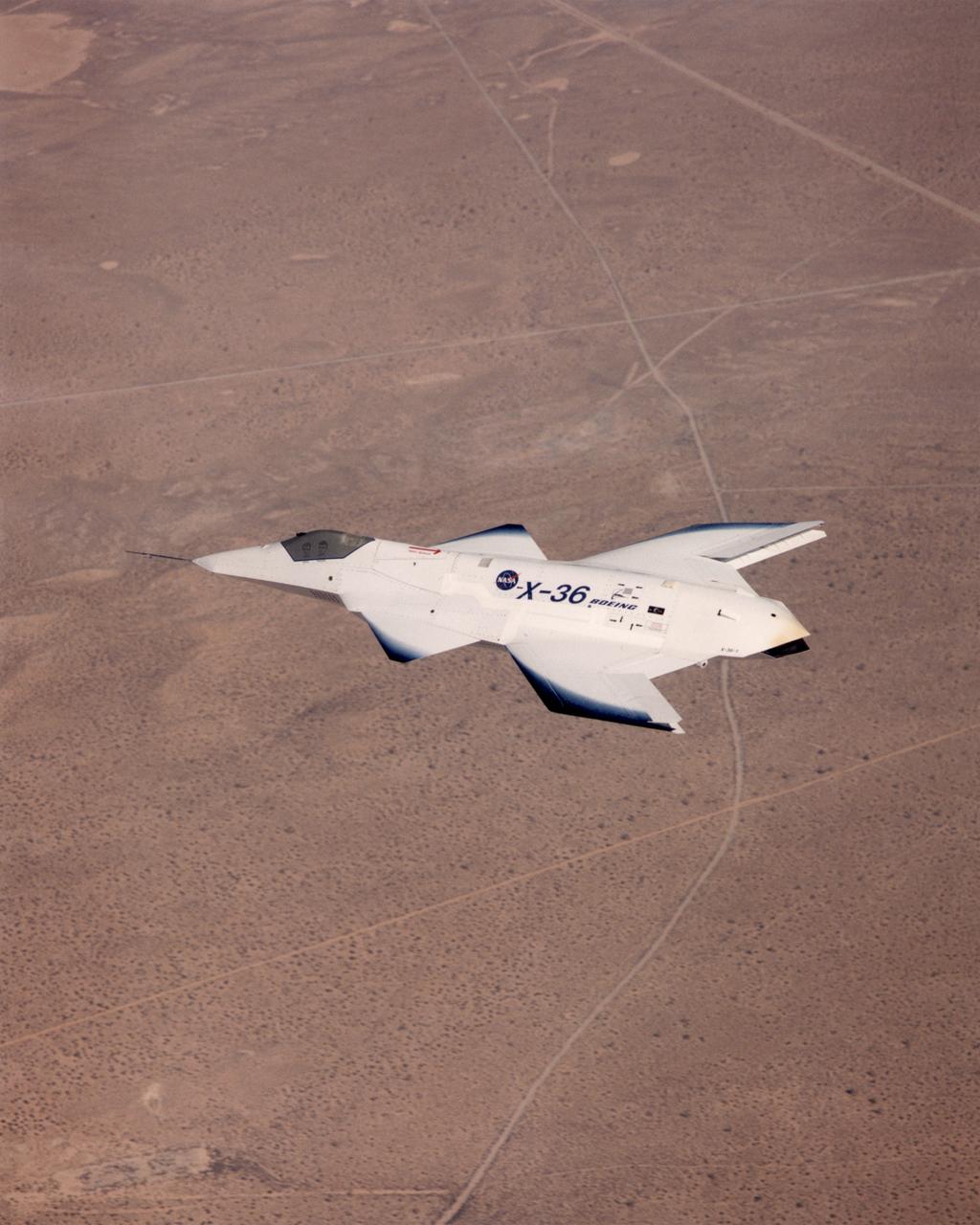
The tailless X-36 technology demonstrator research aircraft cruises over the California desert at low altitude during a 1997 research flight.
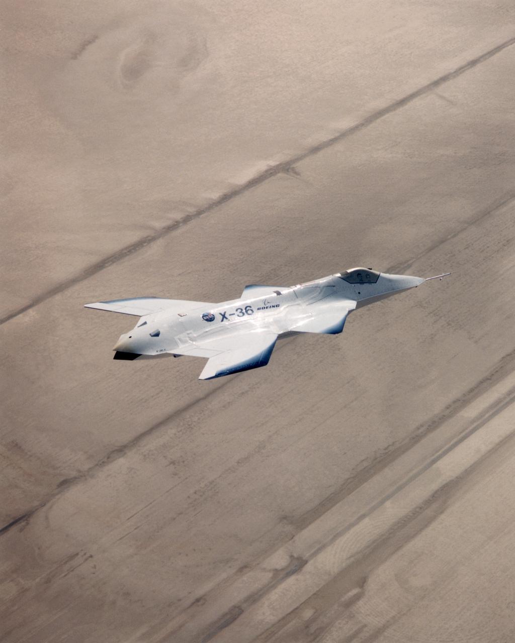
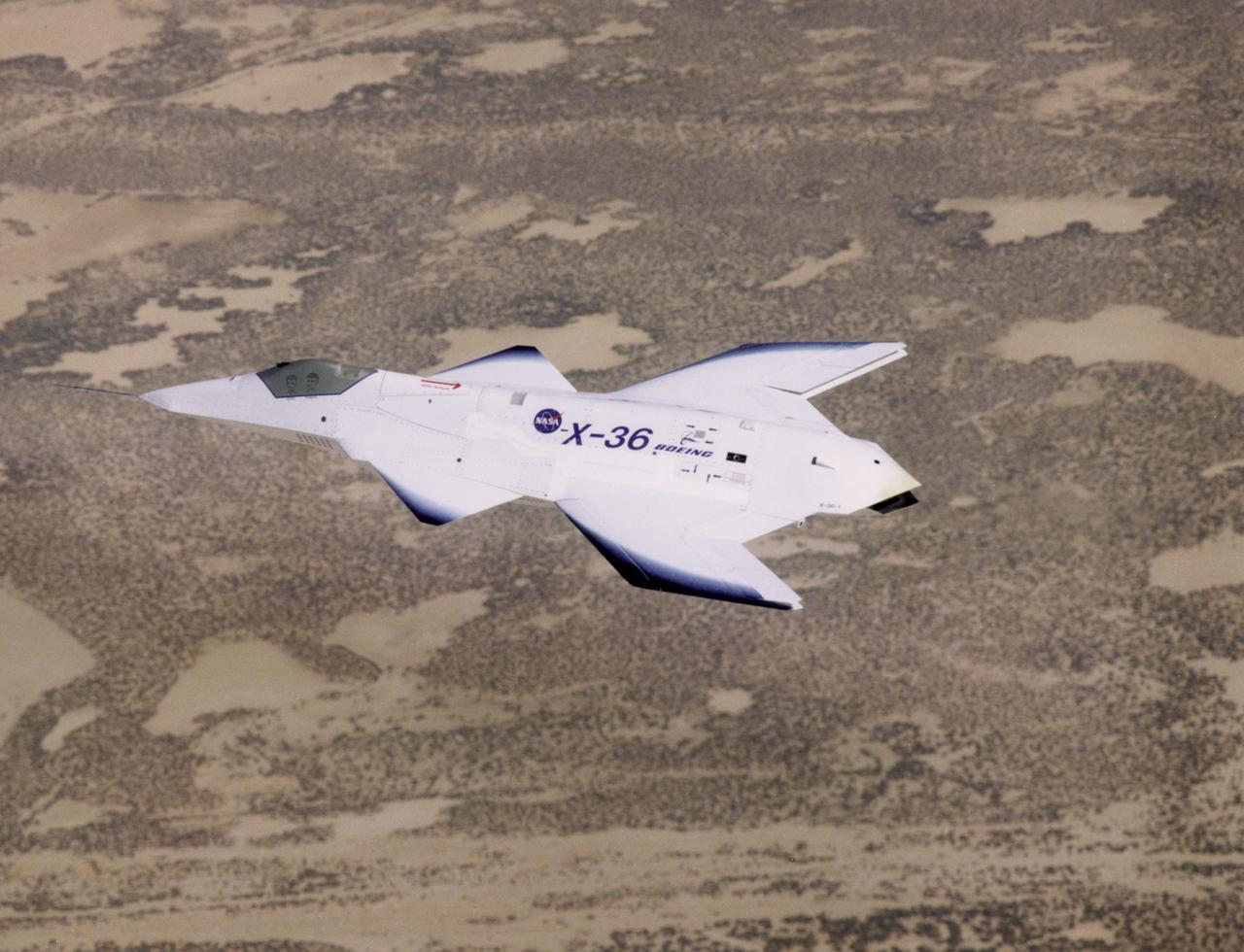
The X-36 technology demonstrator shows off its distinctive shape as the remotely piloted aircraft flies a research mission over the Southern California desert on October 30, 1997.
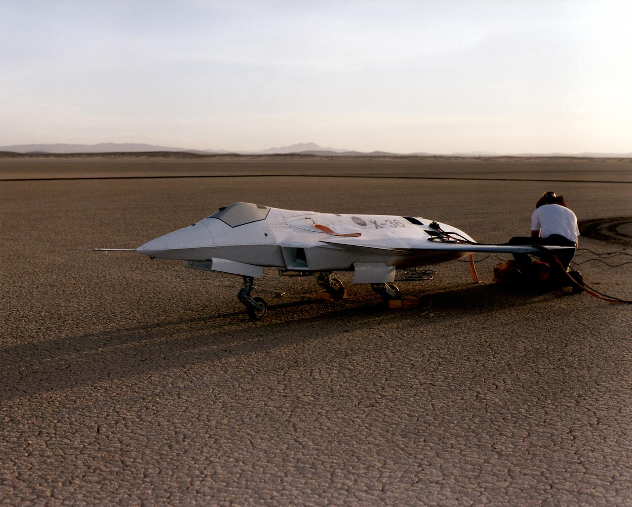
Lit by the rays of the morning sunrise on Rogers Dry Lake, adjacent to NASA's Dryden Flight Research Center, Edwards, California, technicians prepare the remotely-piloted X-36 Tailless Fighter Agility Research Aircraft for its first flight in May 1997.
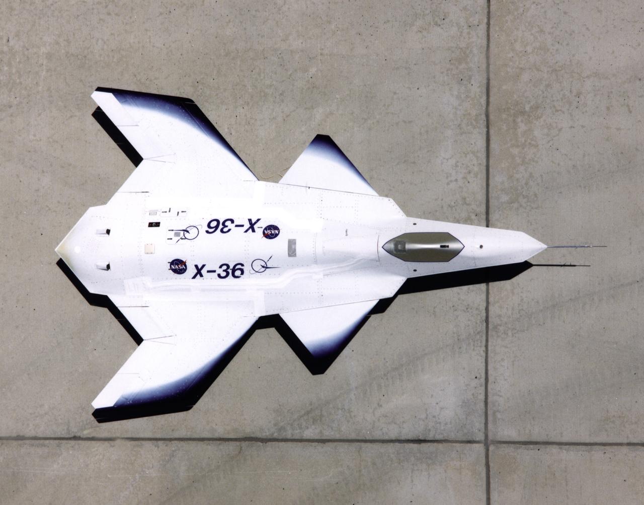
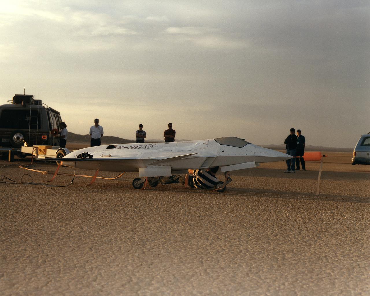
This look-down view of the X-36 Tailless Fighter Agility Research Aircraft on the ramp at NASA’s Dryden Flight Research Center, Edwards, California, clearly shows the unusual wing and canard design of the remotely-piloted aircraft.
The Dryden C-140 JetStar during testing of advanced propfan designs. Dryden conducted flight research in 1981-1982 on several designs. The technology was developed under the direction of the Lewis Research Center (today the Glenn Research Center, Cleveland, OH) under the Advanced Turboprop Program. Under that program, Langley Research Center in Virginia oversaw work on accoustics and noise reduction. These efforts were intended to develop a high-speed and fuel-efficient turboprop system.
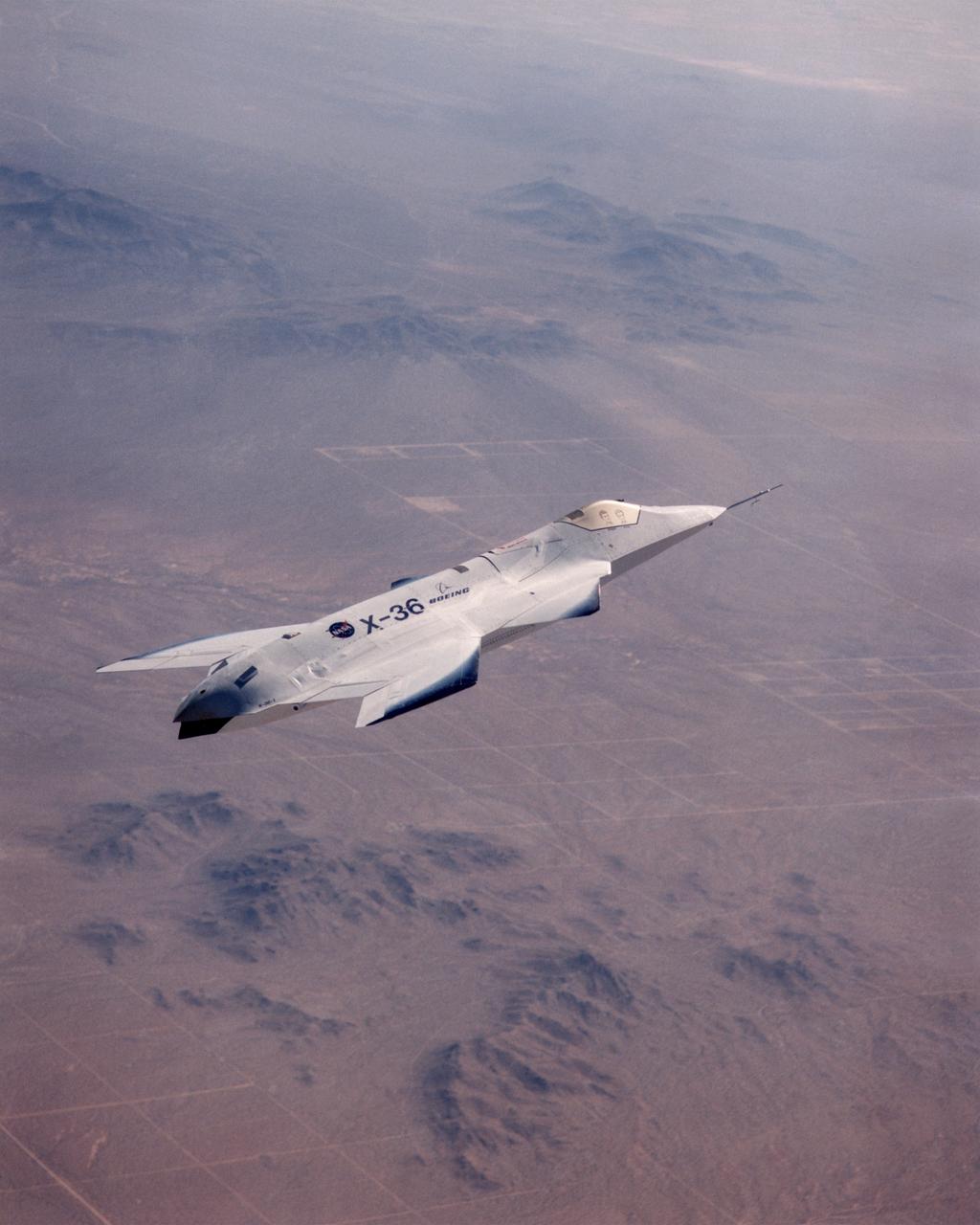
The X-36 technology demonstrator shows off its distinctive shape as the remotely piloted aircraft flies a research mission over the Southern California desert on October 30, 1997.
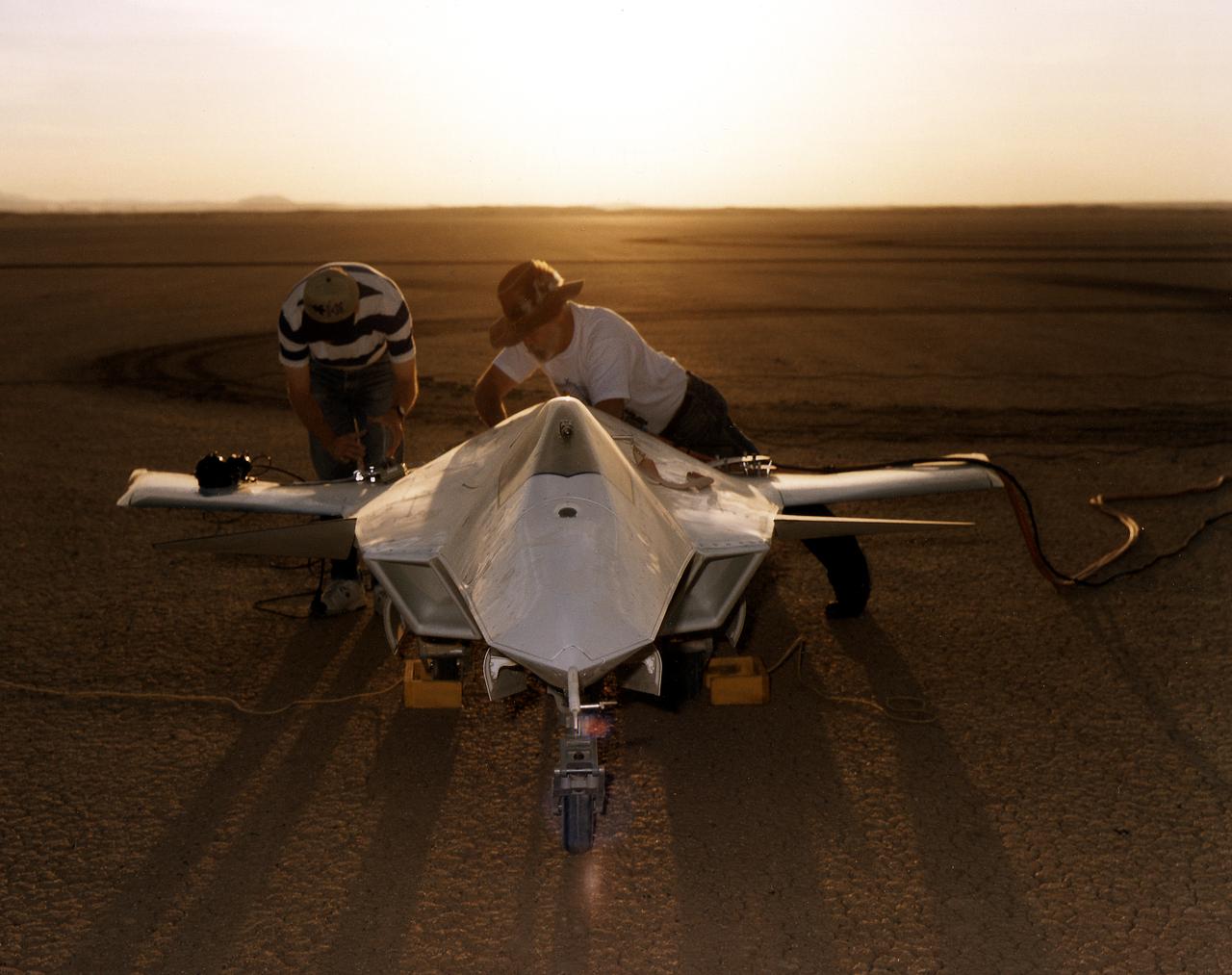
As the sun creeps above the horizon of Rogers Dry Lake at NASA's Dryden Flight Research Center, Edwards, California, technicians make final preparations for the first flight of the X-36 Tailless Fighter Agility Research Aircraft.
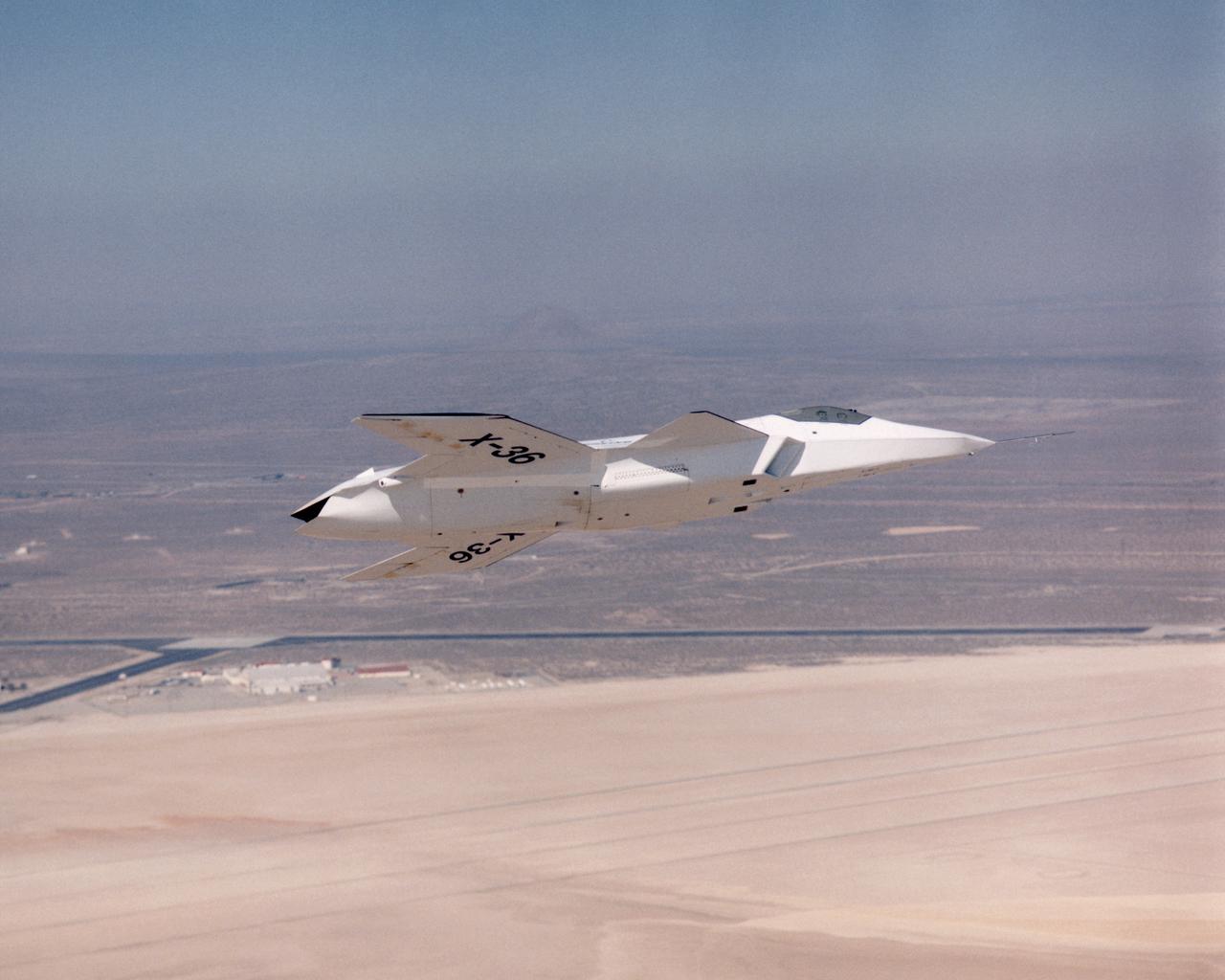
The lack of a vertical tail on the X-36 technology demonstrator is evident as the remotely piloted aircraft flies a low-altitude research flight above Rogers Dry Lake at Edwards Air Force Base in the California desert on October 30, 1997.
Lit by the rays of the morning sunrise on Rogers Dry Lake, adjacent to NASA's Dryden Flight Research Center, Edwards, California, technicians prepares the remotely-piloted X-36 Tailless Fighter Agility Research Aircraft for its first flight on May 17, 1997.
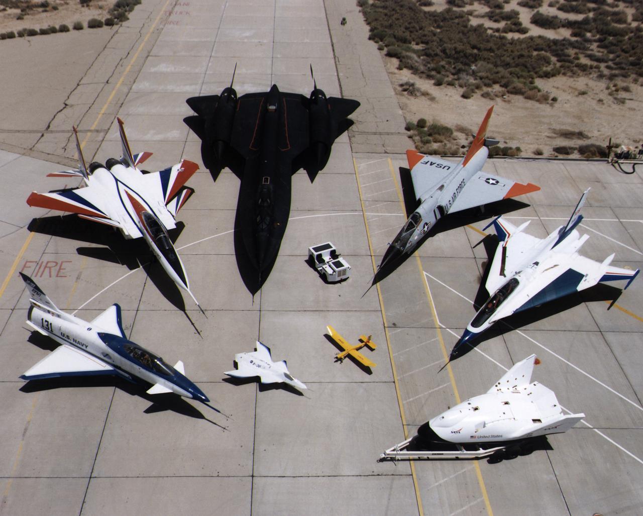
A collection of NASA's research aircraft on the ramp at the Dryden Flight Research Center in July 1997: X-31, F-15 ACTIVE, SR-71, F-106, F-16XL Ship #2, X-38, Radio Controlled Mothership and X-36.