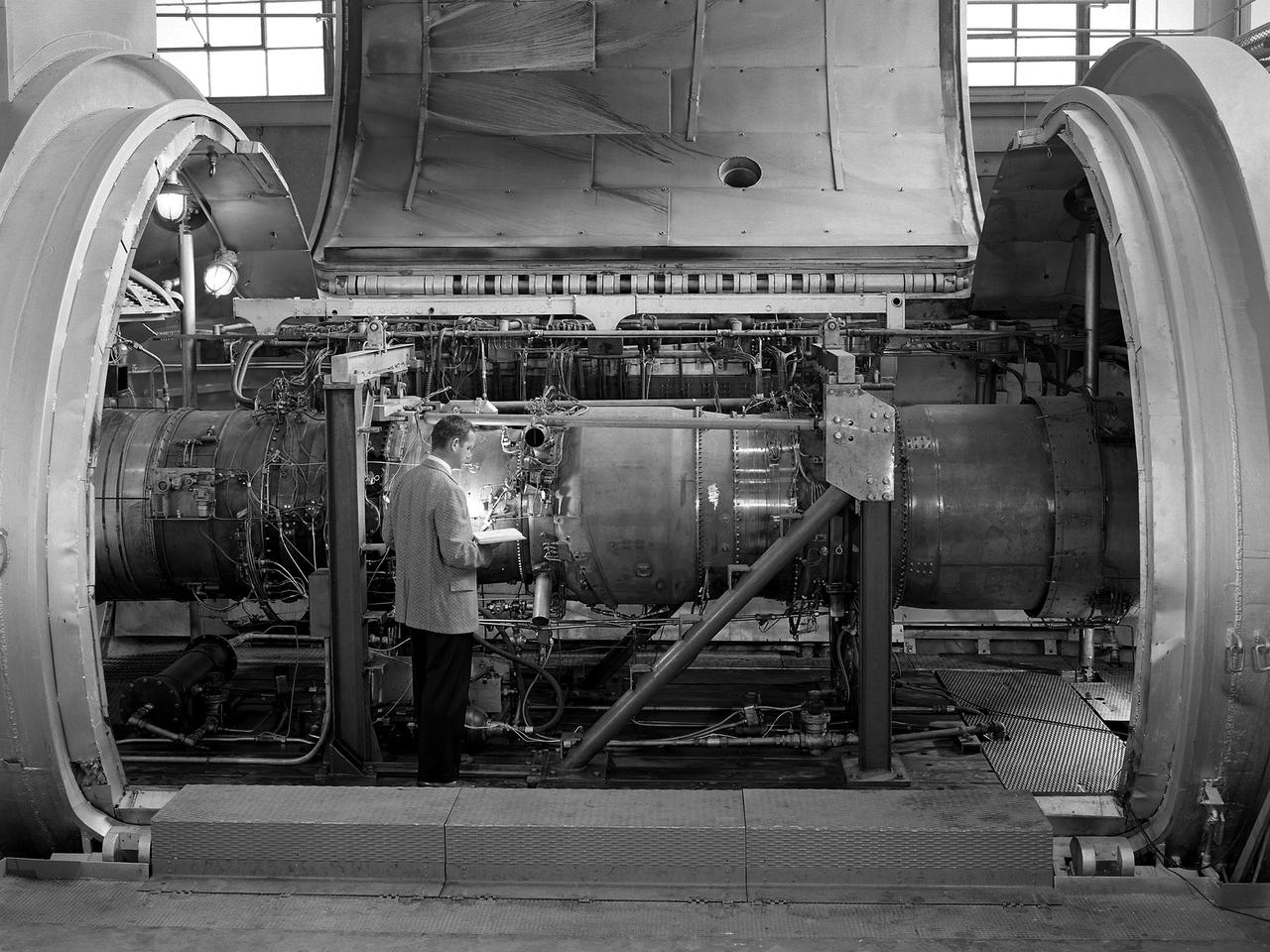
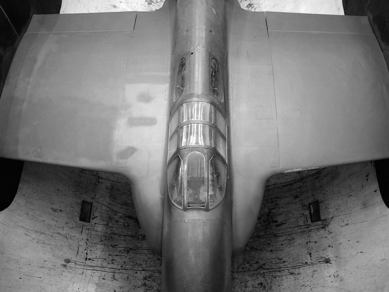
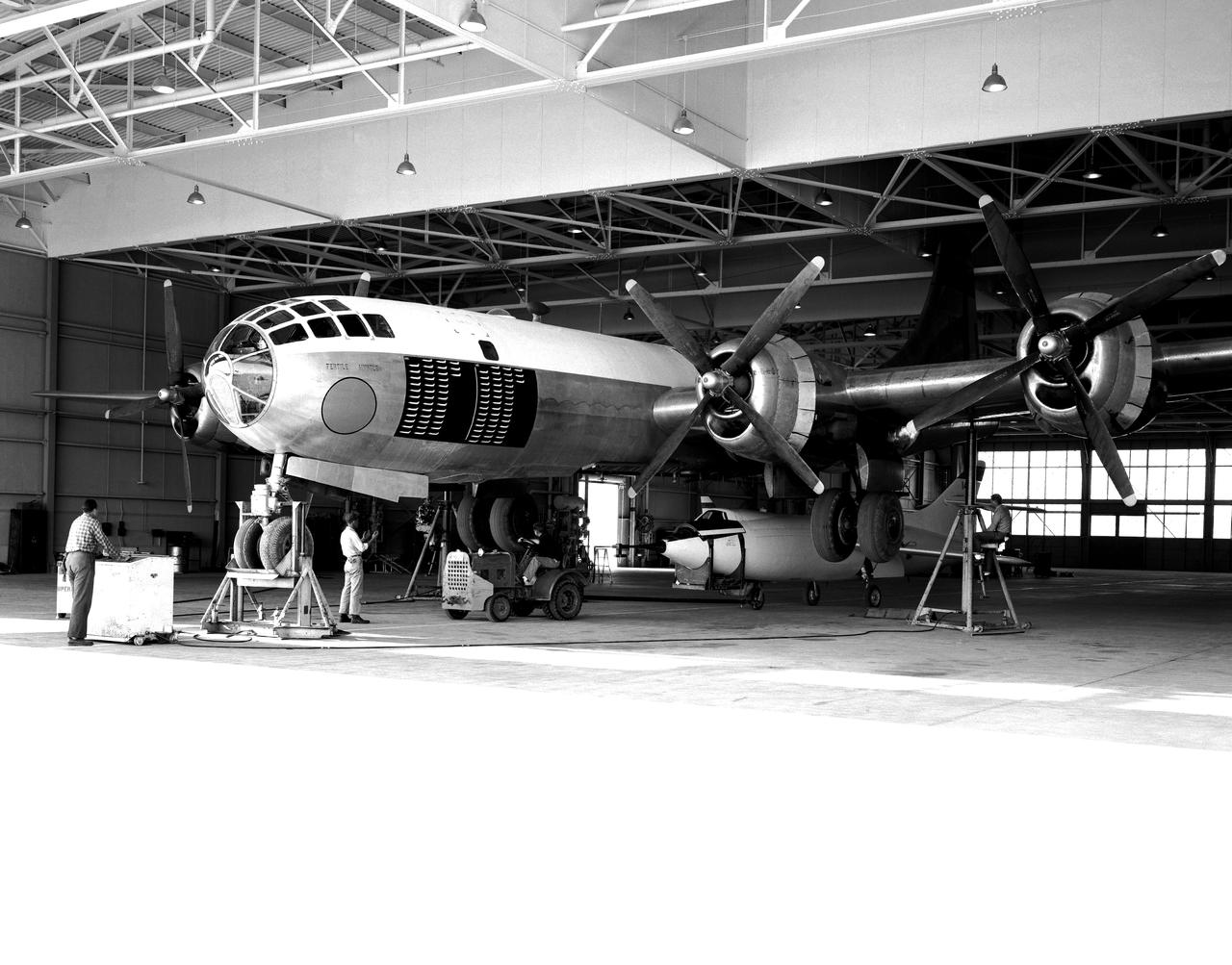
The National Advisory Committee for Aeronautics (NACA) Lewis Flight Propulsion Laboratory conducted an extensive icing research program in the late 1940s that included studies in the Icing Research Tunnel and using specially modified aircraft. One facet of this program was the investigation of the effects of icing on turbojets. Although jet engines allowed aircraft to pass through inclement weather at high rates of speed, ice accumulation was still a concern. The NACA’s B-24M Liberator was initially reconfigured with a General Electric I-16 engine installed in the aircraft’s waist compartment with an air scoop and spray nozzles to produce the artificial icing conditions. The centrifugal engine appeared nearly impervious to the effects of icing. Axial-flow jet engines, however, were much more susceptible to icing damage. The inlet guide vanes were particularly vulnerable, but the cowling’s leading edge, the main bearing supports, and accessory housing could also ice up. If pieces of ice reached the engine’s internal components, the compressor blades could be damaged. To study this phenomenon, a Westinghouse 24C turbojet, seen in this photograph, was installed under the B-24M’s right wing. In January 1948 flight tests of the 24C in icing conditions began. Despite ice buildup into the second stage of the compressor, the engine was able to operate at takeoff speeds. Researchers found the ice on the inlet vanes resulted in half of the engine’s decreased performance.
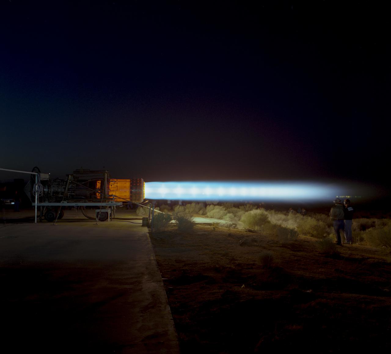
A J58 turbojet used in Lockheed SR-71s which NASA flew, during an engine run. The engine, anchored to the ground, is in full afterburner and parts of the engine are glowing.
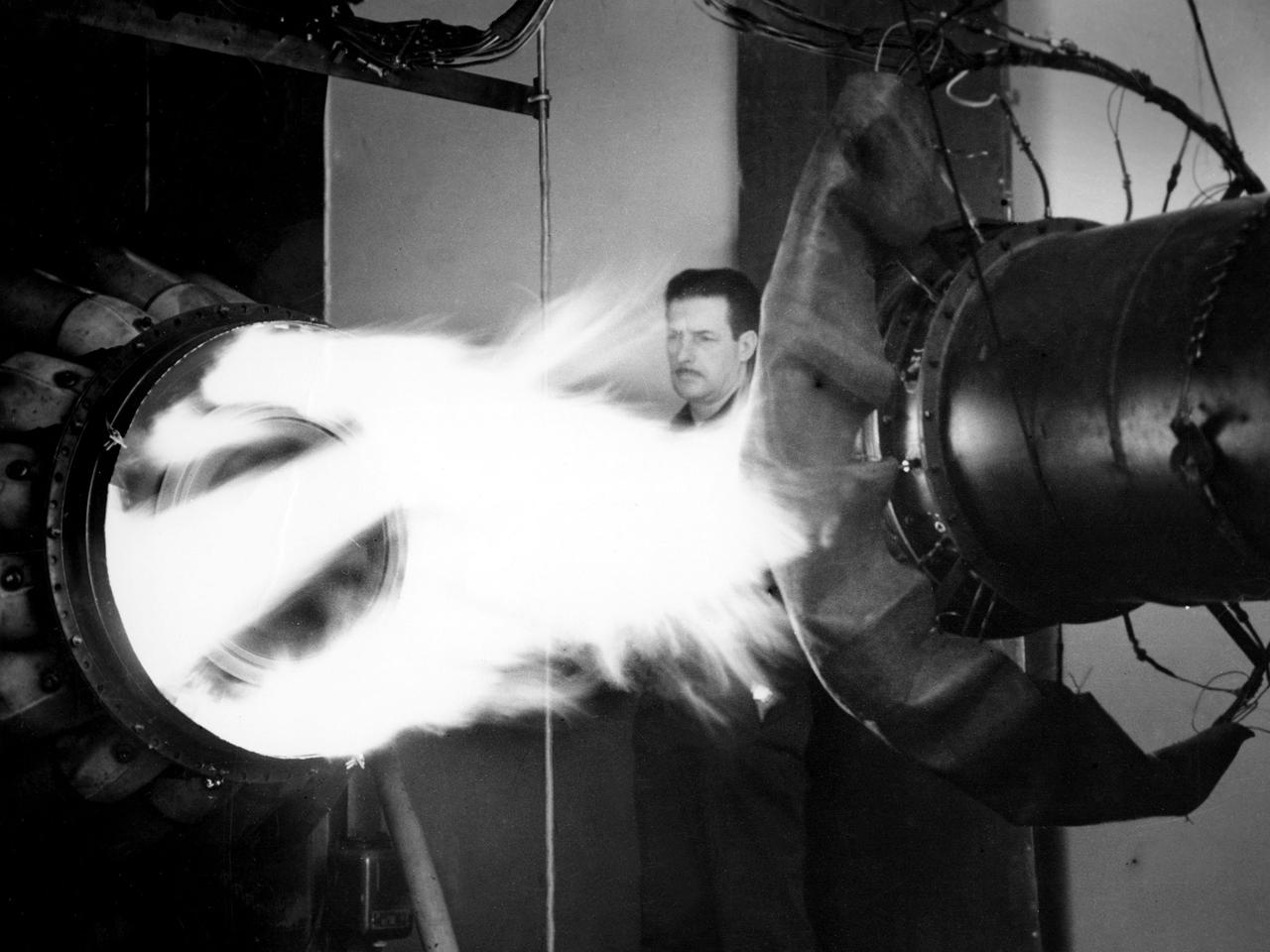
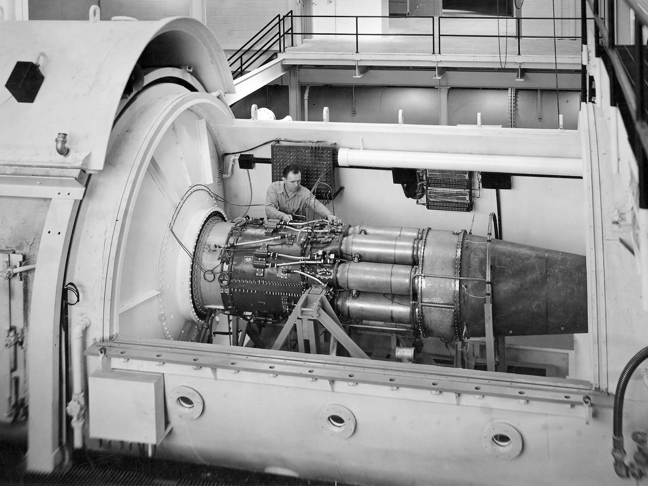
A mechanic watches the firing of a General Electric I-40 turbojet at the National Advisory Committee for Aeronautics (NACA) Lewis Flight Propulsion Laboratory. The military selected General Electric’s West Lynn facility in 1941 to secretly replicate the centrifugal turbojet engine designed by British engineer Frank Whittle. General Electric’s first attempt, the I-A, was fraught with problems. The design was improved somewhat with the subsequent I-16 engine. It was not until the engine's next reincarnation as the I-40 in 1943 that General Electric’s efforts paid off. The 4000-pound thrust I-40 was incorporated into the Lockheed Shooting Star airframe and successfully flown in June 1944. The Shooting Star became the US’s first successful jet aircraft and the first US aircraft to reach 500 miles per hour. NACA Lewis studied all of General Electric’s centrifugal turbojet models during the 1940s. In 1945 the entire Shooting Star aircraft was investigated in the Altitude Wind Tunnel. Engine compressor performance and augmentation by water injection; comparison of different fuel blends in a single combustor; and air-cooled rotors were studied. The mechanic in this photograph watches the firing of a full-scale I-40 in the Jet Propulsion Static Laboratory. The facility was quickly built in 1943 specifically in order to test the early General Electric turbojets. The I-A was secretly analyzed in the facility during the fall of 1943.
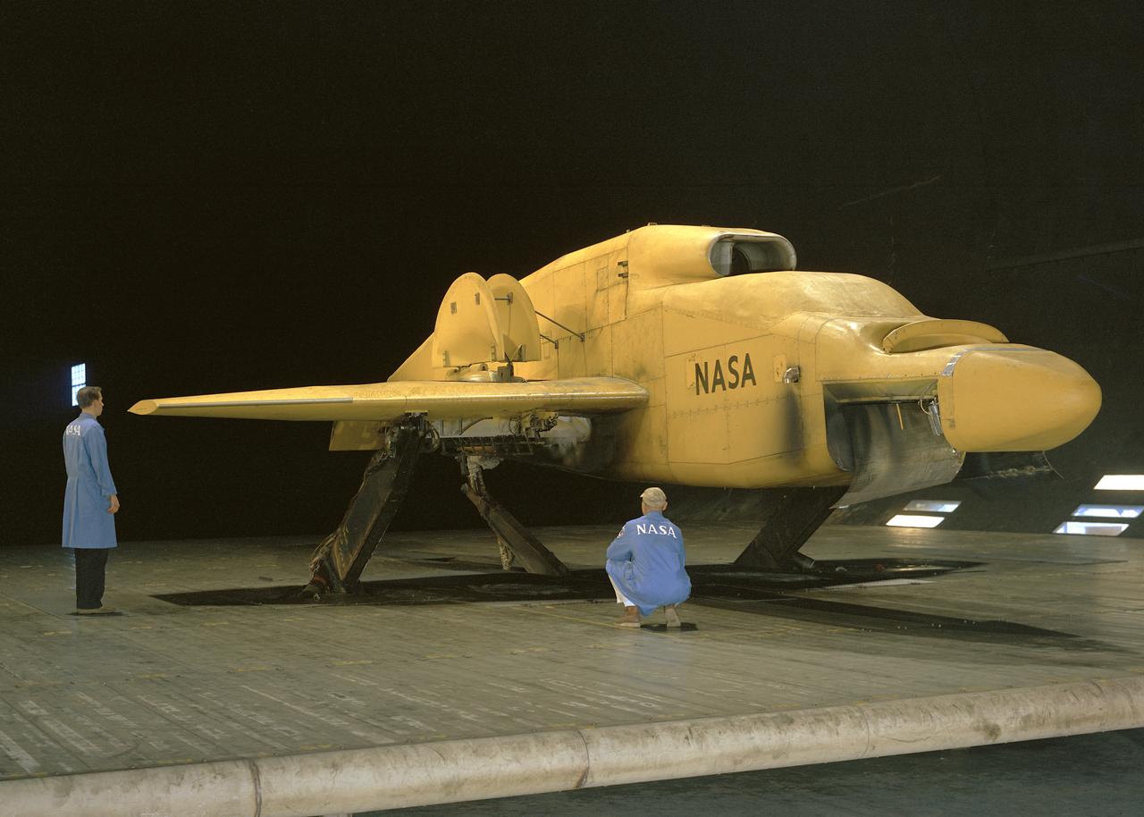
3/4 front view VZ-11 ground test - variable height struts. Engines of the VZ-11 are a pair of General Electric J85-5 turbojets, mounted in high in the centre fuselage, well away from fan disturbance. Designed in the Ames 40x80 foot wind tunnel.
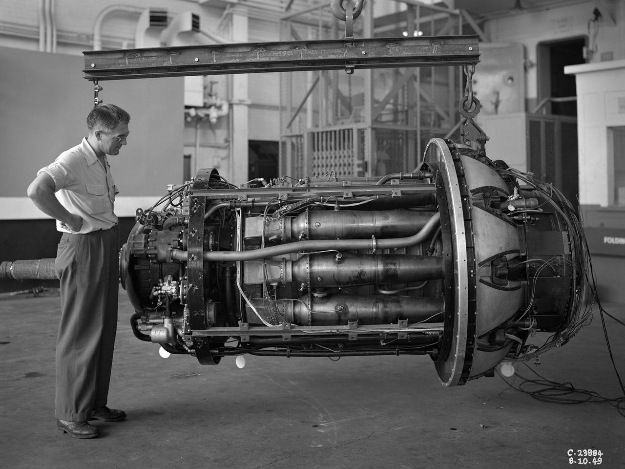
The Westinghouse 19XB turbojet seen from the side in the Altitude Wind Tunnel (AWT) test section at the National Advisory Committee for Aeronautics (NACA) Aircraft Engine Research Laboratory. Westinghouse started the development of a series of relatively small axial-flow turbojets for the Navy shortly after Pearl Harbor. In 1943 the 19A engine became both the first operational US-designed jet engine and the only U.S. turbojet incorporated into an aircraft during the war in Europe. In March 1943 Westinghouse agreed to create an improved six-stage 1400-pound thrust version, the 19B. The engine underwent its first test run a year later in March 1944. Almost immediately the navy agreed to Westinghouse’s proposal for the even larger 10-stage, 1600-pound-thrust 19XB prototype. By July 1944 the navy had contracted with the NACA for the testing of both engines in the AWT. The tunnel was the nation’s only facility for studying full-scale engines in simulated altitude conditions. The wind tunnel investigations, which began on September 9, 1944, revealed the superiority of the previously untested 19XB over the 19B. The 19B engines failed to restart consistently and suffered combustion blowouts above 17,000 feet. The 19XB, however, performed well and restarted routinely at twice that altitude. Two months later on January 26, 1945, two 19Bs powered a McDonnell XFD–1 Phantom, the US Navy’s first fighter jet, on its initial flight. Following its exceptional performance in the AWT, the 19XB engines soon replaced the 19Bs in the Phantom.
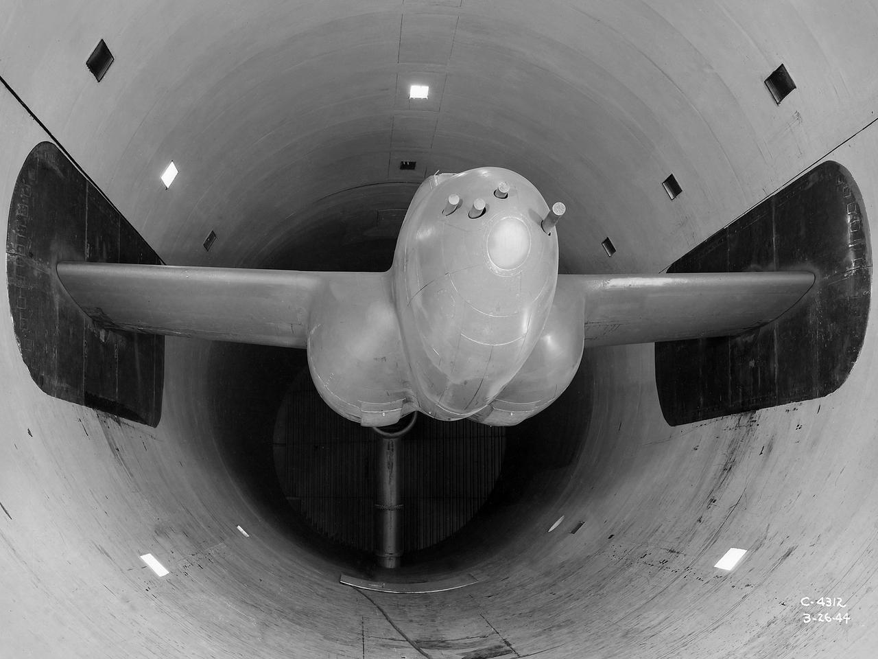
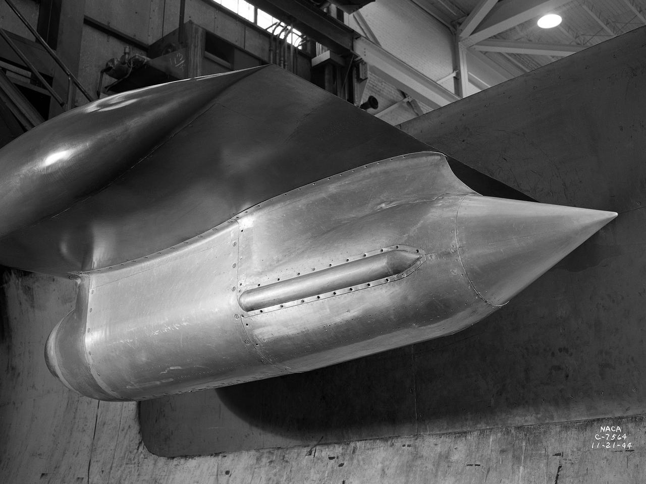
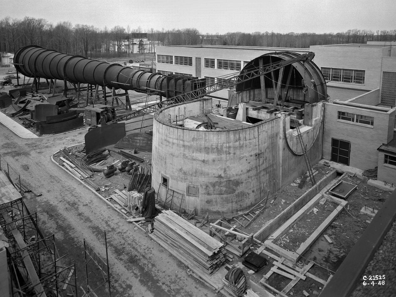
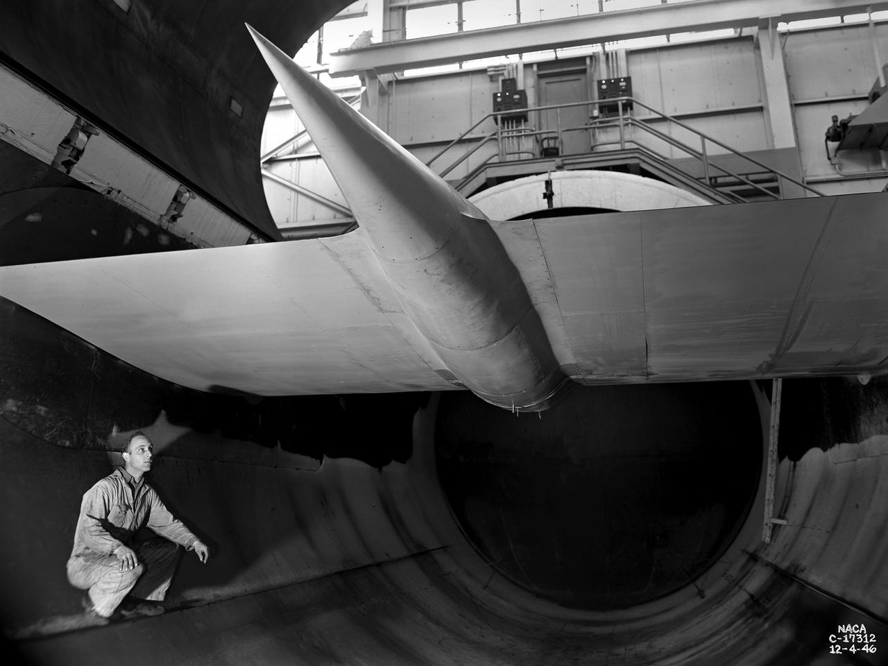
The Altitude Wind Tunnel (AWT) was the National Advisory Committee for Aeronautics (NACA) Aircraft Engine Research Laboratory’s largest and most important test facility in the 1940s. The AWT employed massive cooling and exhaust systems to simulate conditions found at high altitudes. The facility was originally designed to test large piston engines in a simulated flight environment. The introduction of the turbojet during the tunnel’s construction, however, changed the facility’s focus before it became operational. Its first test program was a study of the Bell YP–59A Airacomet and its General Electric I–16 turbojets. The Airacomet was the United States’ first attempt to build a jet aircraft. 1600-horsepower centrifugal engines based on an early design by British engineer Frank Whittle were incorporated into an existing Bell airframe. In October 1942 the Airacomet was secretly test flown in the California desert. The aircraft’s performance was limited, however, and the NACA was asked to study the engines in the AWT. The wind tunnel’s 20-foot-diameter test section was large enough to accommodate entire aircraft with its wing tips and tail removed. The I-16 engines were studied exhaustively in early 1944. They first analyzed the engines in their original configuration and then implemented a boundary layer removal duct, a new nacelle inlet, and new cooling seals. Tests of the modified version showed that the improved distribution of airflow increased the I–16’s performance by 25 percent. The Airacomet never overcame some of its inherent design issues, but the AWT went on to study nearly every emerging US turbojet model during the next decade.

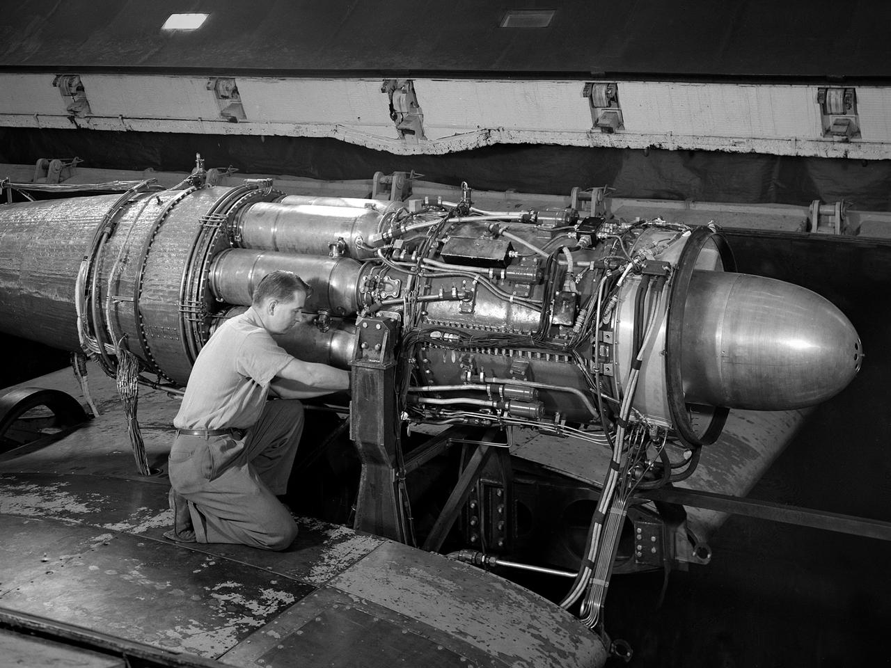
A mechanic works on a General Electric I-40 turbojet at the National Advisory Committee for Aeronautics (NACA) Lewis Flight Propulsion Laboratory. The military selected General Electric’s West Lynn facility in 1941 to secretly replicate the centrifugal turbojet engine designed by British engineer Frank Whittle. General Electric’s first attempt, the I-A, was fraught with problems. The design was improved somewhat with the subsequent I-16 engine. It was not until the engine's next reincarnation as the I-40 in 1943 that General Electric’s efforts paid off. The 4000-pound thrust I-40 was incorporated into the Lockheed Shooting Star airframe and successfully flown in June 1944. The Shooting Star became the US’s first successful jet aircraft and the first US aircraft to reach 500 miles per hour. The NACA’s Lewis Flight Propulsion Laboratory studied all of General Electric’s centrifugal turbojets both during World War II and afterwards. The entire Shooting Star aircraft was investigated in the Altitude Wind Tunnel during 1945. The researchers studied the engine compressor performance, thrust augmentation using a water injection, and compared different fuel blends in a single combustor. The mechanic in this photograph is inserting a combustion liner into one of the 14 combustor cans. The compressor, which is not yet installed in this photograph, pushed high pressure air into these combustors. There the air mixed with the fuel and was heated. The hot air was then forced through a rotating turbine that powered the engine before being expelled out the nozzle to produce thrust.
A .10-scale model of Convair’s XF-102 in the 8- by 6-Foot Supersonic Wind Tunnel at the National Advisory Committee for Aeronautics (NACA) Lewis Flight Propulsion Laboratory for jet exit studies. The XF-102 was a prototype of the F-102 Delta Dagger. The F-102 served as an interceptor against long range bombers from the Soviet Union. The aircraft was powered by a Pratt and Whitney J57 turbojet. The first prototype crashed two weeks after is first flight on October 24, 1953, just months after this photograph. Engineers then incorporated the fixed-wing design to reduce drag at supersonic speeds. The production model F-102 became the first delta-wing supersonic aircraft in operation. The 8- by 6-Foot Supersonic Wind Tunnel is used to study propulsion systems, including inlets and exit nozzles, combustion fuel injectors, flame holders, exit nozzles, and controls on ramjet and turbojet engines. Flexible sidewalls alter the tunnel’s nozzle shape to vary the Mach number during operation. A seven-stage axial compressor, driven by three electric motors that yield a total of 87,000 horsepower, generates air speeds from Mach 0.36 to 2.0.
A Rolls Royce Avon RA-14 engine was tested in the Altitude Wind Tunnel at the National Advisory Committee for Aeronautics’ (NACA) Lewis Flight Propulsion Laboratory. The Avon RA-14 engine was a 16-stage axial-flow compressor turbojet capable of producing 9,500 pounds of thrust. The Avon replaced Rolls Royce’s successful Nene engine in 1950 and remained in service until 1974. It was one of several British engines studied in the tunnel during the 1950s. The Altitude Wind Tunnel went through a series of modifications in 1951 to increase its capabilities. An annex was attached to the Exhauster Building to house three new Ingersoll-Rand compressors. The wooden blades on the tunnel’s 31-foot diameter fan were replaced, a pump house and exhaust cooler were constructed underneath the tunnel, and two new cells were added to the cooling tower. The modified wind tunnel continued to analyze jet engines in the 1950s, although the engines, like the RA-14 seen here, were much more powerful than those studied several years before. Lewis researchers studied the RA-14 turbojet engine in the Altitude Wind Tunnel for 11 months in 1956. The engine was mounted on a stand capable of gauging engine thrust, and the tunnel’s air was ducted to the engine through a venturi and bellmouth inlet, seen in this photograph. The initial studies established the engine’s performance characteristics with a fixed-area nozzle and its acceleration characteristics. The researchers also used the tunnel to investigate windmilling of the compressor blades, restarting at high altitudes, and the engine’s performance limits at altitude.
The 8- by 6-Foot Supersonic Wind Tunnel at the National Advisory Committee for Aeronautics (NACA) Lewis Flight Propulsion Laboratory was the nation’s largest supersonic facility when it began operation in April 1949. The emergence of new propulsion technologies such as turbojets, ramjets, and rockets during World War II forced the NACA and the aircraft industry to develop new research tools. In late 1945 the NACA began design work for new large supersonic wind tunnels at its three laboratories. The result was the 4- by 4-Foot Supersonic Wind Tunnel at Langley Memorial Aeronautical Laboratory, 6- by 6-foot supersonic wind tunnel at Ames Aeronautical Laboratory, and the largest facility, the 8- by 6-Foot Supersonic Wind Tunnel in Cleveland. The two former tunnels were to study aerodynamics, while the 8- by 6 facility was designed for supersonic propulsion. The 8- by 6-Foot Supersonic Wind Tunnel was used to study propulsion systems, including inlets and exit nozzles, combustion fuel injectors, flame holders, exit nozzles, and controls on ramjet and turbojet engines. Flexible sidewalls alter the tunnel’s nozzle shape to vary the Mach number during operation. A seven-stage axial compressor, driven by three electric motors that yield a total of 87,000 horsepower, generates air speeds from Mach 0.36 to 2.0. A section of the tunnel is seen being erected in this photograph.
A researcher examines the Orenda Iroquois PS.13 turbojet in a Propulsion Systems Laboratory test chamber at the National Advisory Committee for Aeronautics (NACA) Lewis Flight Propulsion Laboratory. The Iroquois was being developed to power the CF-105 Arrow fighter designed by the Avro Canada Company. Avro began design work on the Arrow jet fighter in 1952. The company’s Orenda branch suggested building a titanium-based PS.13 Iroquois engine after development problems arose with the British engines that Avro had originally intended to use. The 10-stage, 20,000-pound-thrust Iroquois would prove to be more powerful than any contemporary US or British turbojet. It was also significantly lighter and more fuel efficient. An Iroquois was sent to Cleveland in April 1957 so that Lewis researchers could study the engine’s basic performance for the air force in the Propulsion Systems Laboratory. The tests were run over a wide range of speeds and altitudes with variations in exhaust-nozzle area. Initial studies determined the Iroquois’s windmilling and ignition characteristics at high altitude. After operating for 64 minutes, the engine was reignited at altitudes up to the 63,000-foot limit of the facility. Various modifications were attempted to reduce the occurrence of stall but did not totally eradicate the problem. The Arrow jet fighter made its initial flight in March 1958 powered by a substitute engine. In February 1959, however, both the engine and the aircraft programs were cancelled. The world’s superpowers had quickly transitioned from bombers to ballistic missiles which rendered the Avro Arrow prematurely obsolete.
A 3670-horsepower Armstrong-Siddeley Python turboprop being prepared for tests in the Altitude Wind Tunnel at the National Advisory Committee for Aeronautics (NACA) Lewis Flight Propulsion Laboratory. In 1947 Lewis researcher Walter Olsen led a group of representatives from the military, industry, and the NACA on a fact finding mission to investigate the technological progress of British turbojet manufacturers. Afterwards several British engines, including the Python, were brought to Cleveland for testing in Lewis’s altitude facilities. The Python was a 14-stage axial-flow compressor turboprop with a fixed-area nozzle and contra-rotating propellers. Early turboprops combined the turbojet and piston engine technologies. They could move large quantities of air so required less engine speed and thus less fuel. This was very appealing to the military for some applications. The military asked the NACA to compare the Python’s performance at sea to that at high altitudes. The NACA researchers studied the Python in the Altitude Wind Tunnel from July 1949 through January 1950. It was the first time the tunnel was used to study an engine with the sole purpose of learning about, not improving it. They analyzed the engine’s dynamic response using a frequency response method at altitudes between 10,000 to 30,000 feet. Lewis researchers found that they could predict the dynamic response characteristics at any altitude from the data obtained from any other specific altitude. This portion of the testing was completed during a single test run.
A Martin B-57B Canberra outfitted with a noise suppressor on its right engine at the National Aeronautics and Space Administration (NASA) Lewis Research Center. The aircraft was being prepared for the October 1966 Inspection of the center. The Inspection also marked Lewis’ twentieth anniversary. Lewis researchers had been studying engine noise for almost a decade, but the problem seemed to be increasing in the mid-1960s with heavier airline traffic and larger engines. Researchers discovered early on that the majority of the noise did not emanate from the engine itself, but from the mixing of the hot exhaust gasses with the atmosphere. Attempts to reduce the turbulence using new exhaust nozzles were successful but often resulted in decreased engine performance. The researchers decided to try to lower the jet nozzle exit velocity without decreasing its thrust. The inlet mass air flow had to be increased to accomplish this. The Lewis B-57B was powered by two Wright Aeronautical J65 turbojets. Lewis engineers modified the stators on the two engines to simulate the noise levels from more-modern turbofan engines. A noise suppressor was added to only one of the two engines, seen here on the left. The engines were run one at a time at power levels similar to landing while the aircraft sat on the Lewis hangar apron. A microphone and recording equipment was setup to capture the noise levels. The engine with the suppressor produced 13 fewer decibels than the standard engine.
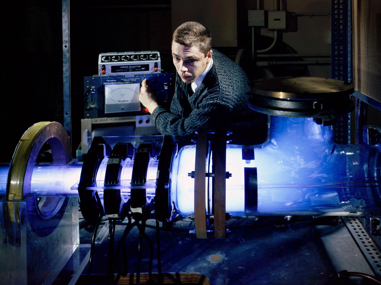
Raymond Palmer, of the Electromagnetic Propulsion Division’s Plasma Flow Section, adjusts the traveling magnetic wave plasma engine being operated in the Electric Power Conversion at the National Aeronautics and Space Administration (NASA) Lewis Research Center. During the 1960s Lewis researchers were exploring several different methods of creating electric propulsion systems, including the traveling magnetic wave plasma engine. The device operated similarly to alternating-current motors, except that a gas, not a solid, was used to conduct the electricity. A magnetic wave induced a current as it passed through the plasma. The current and magnetic field pushed the plasma in one direction. Palmer and colleague Robert Jones explored a variety of engine configurations in the Electric Propulsion Research Building. The engine is seen here mounted externally on the facility’s 5-foot diameter and 16-foot long vacuum tank. The four magnetic coils are seen on the left end of the engine. The researchers conducted two-minute test runs with varying configurations and used of both argon and xenon as the propellant. The Electric Propulsion Research Building was built in 1942 as the Engine Propeller Research Building, often called the Prop House. It contained four test cells to study large reciprocating engines with their propellers. After World War II, the facility was modified to study turbojet engines. By the 1960s, the facility was modified again for electric propulsion research and given its current name.
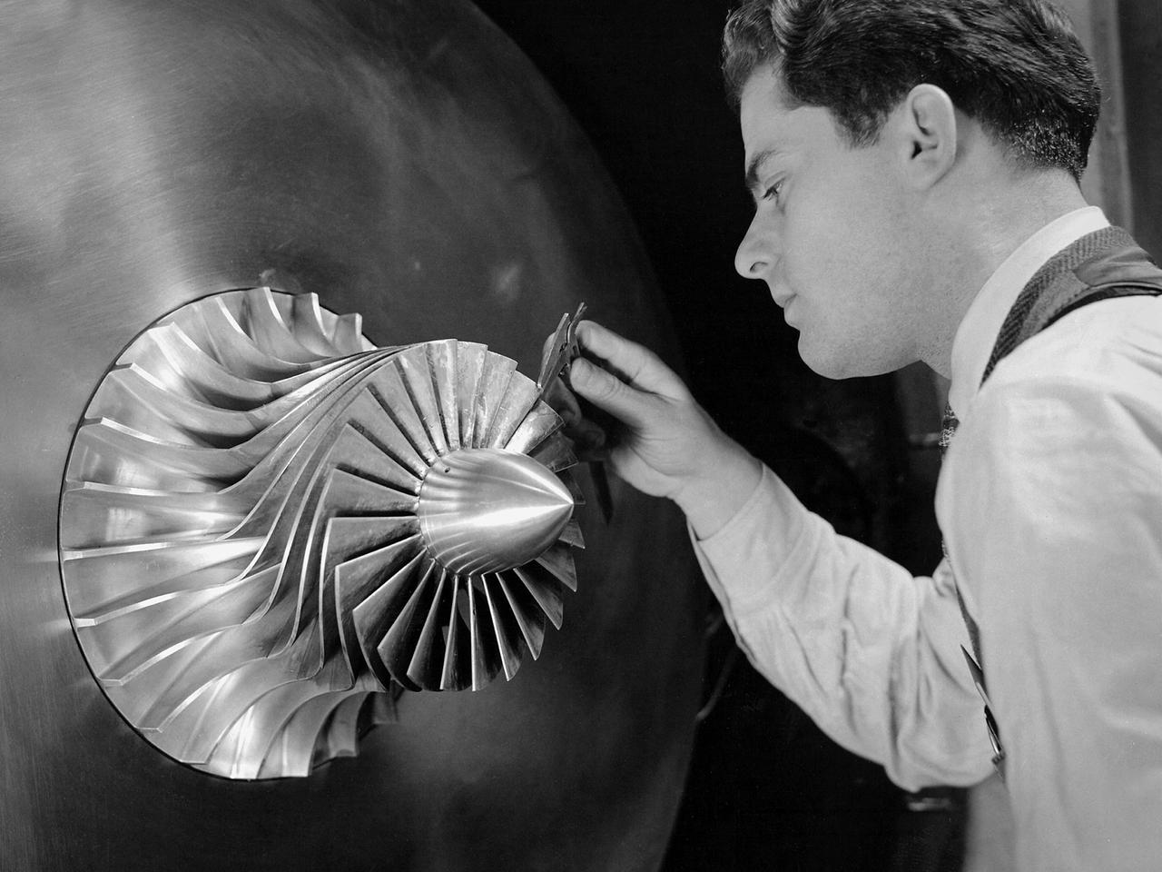
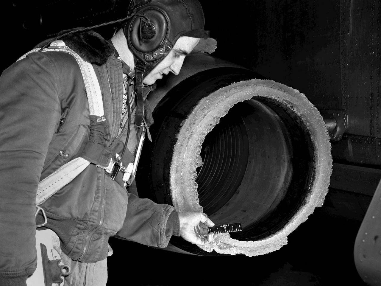
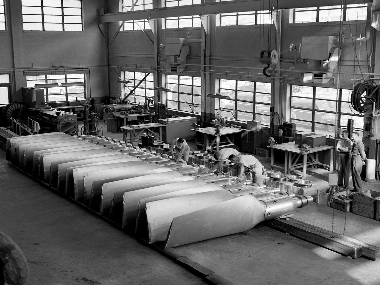
A researcher in the Supercharger Research Division at the National Advisory Committee for Aeronautics (NACA) Aircraft Engine Research Laboratory measures the blade thickness on a supercharger. Superchargers were developed at General Electric used to supply additional air to reciprocating engines. The extra air resulted in increased the engine’s performance, particularly at higher altitudes. The Aircraft Engine Research Laboratory had an entire division dedicated to superchargers during World War II. General Electric developed the supercharger in response to a 1917 request from the NACA to develop a device to enhance high-altitude flying. The supercharger pushed larger volumes of air into the engine manifold. The extra oxygen allowed the engine to operate at its optimal sea-level rating even when at high altitudes. Thus, the aircraft could maintain its climb rate, maneuverability and speed as it rose higher into the sky. NACA work on the supercharger ceased after World War II due to the arrival of the turbojet engine. The Supercharger Research Division was disbanded in October 1945 and reconstituted as the Compressor and Turbine Division.
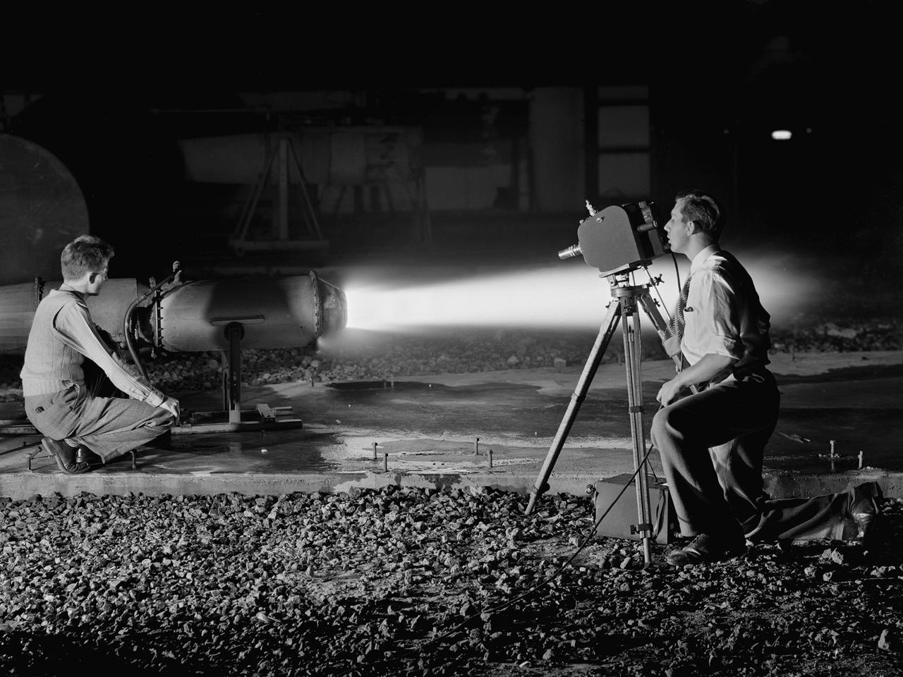
A National Advisory Committee for Aeronautics (NACA) photographer films the test of a ramjet engine at the Lewis Flight Propulsion Laboratory. The laboratory had an arsenal of facilities to test the engines and their components, and immersed itself in the study of turbojet and ramjet engines during the mid-1940s. Combustion, fuel injection, flameouts, and performance at high altitudes were of particular interest to researchers. They devised elaborate schemes to instrument the engines in order to record temperature, pressure, and other data. Many of the tests were also filmed so Lewis researchers could visually review the combustion performance along with the data. The photographer in this image was using high-speed film to document a thrust augmentation study at Lewis’ Jet Static Propulsion Laboratory. The ramjet in this photograph was equipped with a special afterburner as part of a general effort to improve engine performance. Lewis’ Photo Lab was established in 1942. The staff was expanded over the next few years as more test facilities became operational. The Photo Lab’s staff and specialized equipment have been key research tools for decades. They accompany pilots on test flights, use high-speed cameras to capture fleeting processes like combustion, and work with technology, such as the Schlieren camera, to capture supersonic aerodynamics. In addition, the group has documented construction projects, performed publicity work, created images for reports, and photographed data recording equipment.
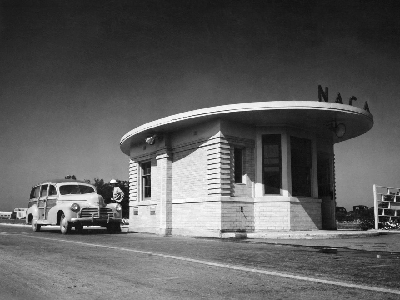
A vehicle leaves the National Advisory Committee for Aeronautics (NACA) Aircraft Engine Research Laboratory on August 14, 1945. At 7 p.m. that evening President Truman announced that Japan had accepted terms for surrender and World War II was over. The end of the war brought significant changes for the laboratory. The NACA would cease its troubleshooting of military aircraft and return to research. Researchers would increase their efforts to address the new technologies that emerged during the war. The entire laboratory was reorganized in October to better investigate turbojets, ramjets, and rockets. The guard house sat on the main entrance to the laboratory off of Brookpark Road. The building was fairly small and easily crowded. In the early 1960s a new security facility was built several hundred feet beyond the original guard house. The original structure remained in place for several years but was not utilized. The subsequent structure was replaced in 2011 by a new building and entrance configuration.

A Republic F-84 Thunderjet dramatically modified at the NASA Lewis Research Center to investigate the use of slotted nozzles to reduce exhaust noise. The F-84 was a single-seat fighter-bomber powered by an Allison J35 turbojet. It was the Air Force’s first post-World War II tactical aircraft and was used extensively in the Korean War. The laboratory had acquired the aircraft in 1954 and modified it in order to demonstrate the reverse thruster. The tail end of the aircraft was then removed for a series of large nozzle investigations. Lewis researchers launched an extensive program in the mid-1950s to develop methods of reducing engine noise as the airline industry was preparing to introduce the first turbojet-powered passenger aircraft. The early NACA investigations determined that the primary source of noise was the mixing of the engine’s hot exhaust with the cool surrounding air. Lewis researchers studied many different nozzles designed to facilitate this mixing. Nozzles with elongated exit sections, as seen in this photograph, produced lower noise levels. These long slot nozzles were also considered for Short Take-off and Landing aircraft because their long flat surfaces provided lift. In 1958 Lewis tested several full-scale slot nozzles on the F-84. The researchers, led by Willard Cole, sought to determine the noise-generation characteristics for nozzles having large a width-to-height ratio. The nozzle in this photograph has a 100 to 1 width-to-height ratio. Cole determined that the experimental nozzles produced the same levels of sound as the standard nozzle, but the changes in the directional noise were substantial.
A General Electric TG-180 turbojet installed in the Altitude Wind Tunnel at the National Advisory Committee for Aeronautics (NACA) Lewis Flight Propulsion Laboratory. In 1943 the military asked General Electric to develop an axial-flow jet engine which became the TG-180. The military understood that the TG-180 would not be ready during World War II but recognized the axial-flow compressor’s long-term potential. Although the engine was bench tested in April 1944, it was not flight tested until February 1946. The TG-180 was brought to the Altitude Wind Tunnel in 1945 for a series of investigations. The studies, which continued intermittently into 1948, analyzed an array of performance issues. NACA modifications steadily improved the TG-180’s performance, including the first successful use of an afterburner. The Lewis researchers studied a 29-inch diameter afterburner over a range of altitude conditions using several different types of flameholders and fuel systems. Lewis researchers concluded that a three-stage flameholder with its largest stage upstream was the best burner configuration. Although the TG-180 (also known as the J35) was not the breakthrough engine that the military had hoped for, it did power the Douglas D-558-I Skystreak to a world speed record on August 20, 1947. The engines were also used on the Republic F-84 Thunderjet and the Northrup F-89 Scorpion.
Construction workers install the drive motor for the Altitude Wind Tunnel (AWT) in the Exhauster Building at the National Advisory Committee for Aeronautics (NACA) Aircraft Engine Research Laboratory. The AWT was capable of operating full-scale engines in air density, speed, and temperature similar to that found at high altitudes. The tunnel could produce wind speeds up to 500 miles per hour through a 20-foot-diameter test section at the standard operating altitude of 30,000 feet. The airflow was created by a large wooden fan near the tunnel’s southeast corner. This photograph shows the installation of the 18,000-horsepower drive motor inside the adjoining Exhauster Building in July 1943. The General Electric motor, whose support frame is seen in this photograph, connected to a drive shaft that extended from the building, through the tunnel shell, and into a 12-bladed, 31-foot-diameter spruce wood fan. Flexible couplings on the shaft allowed for the movement of the shell. The corner of the Exhauster Building was built around the motor after its installation. The General Electric induction motor could produce 10 to 410 revolutions per minute and create wind speeds up to 500 miles per hour, or Mach 0.63, at 30,000 feet. The AWT became operational in January 1944 and tested piston, turbojet and ramjet engines for nearly 20 years.
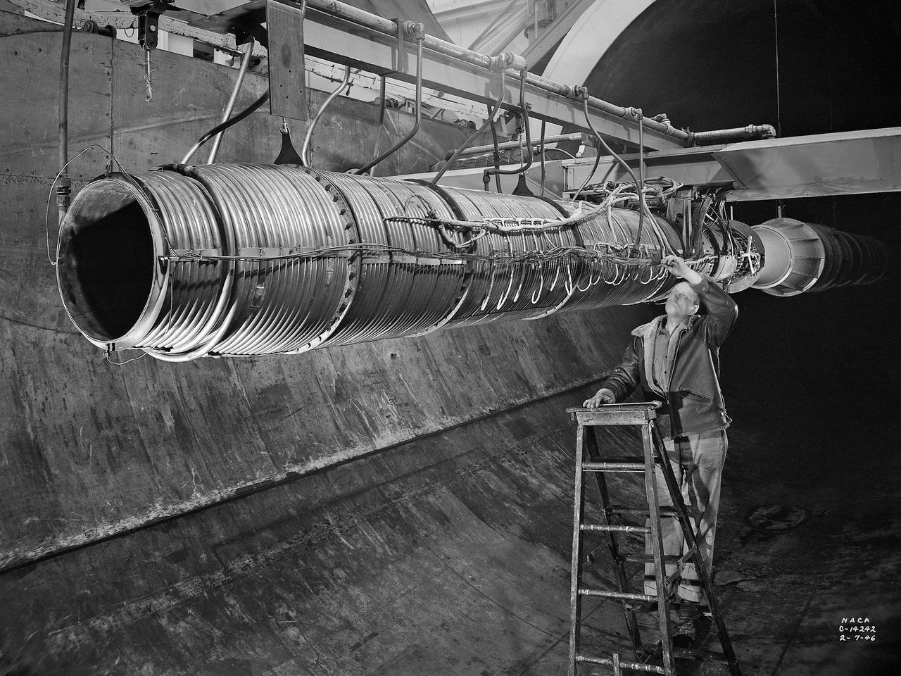
A 20-inch diameter ramjet installed in the Altitude Wind Tunnel at the National Advisory Committee for Aeronautics (NACA) Lewis Flight Propulsion Laboratory. The Altitude Wind Tunnel was used in the 1940s to study early ramjet configurations. Ramjets provide a very simple source of propulsion. They are basically a tube which takes in high-velocity air, ignites it, and then expels the expanded airflow at a significantly higher velocity for thrust. Ramjets are extremely efficient and powerful but can only operate at high speeds. Therefore a turbojet or rocket was needed to launch the vehicle. This NACA-designed 20-inch diameter ramjet was installed in the Altitude Wind Tunnel in May 1945. The ramjet was mounted under a section of wing in the 20-foot diameter test section with conditioned airflow ducted directly to the engine. The mechanic in this photograph was installing instrumentation devices that led to the control room. NACA researchers investigated the ramjet’s overall performance at simulated altitudes up to 47,000 feet. Thrust measurements from these runs were studied in conjunction with drag data obtained during small-scale studies in the laboratory’s small supersonic tunnels. An afterburner was attached to the ramjet during the portions of the test program. The researchers found that an increase in altitude caused a reduction in the engine’s horsepower. They also determined the optimal configurations for the flameholders, which provided the engine’s ignition source.
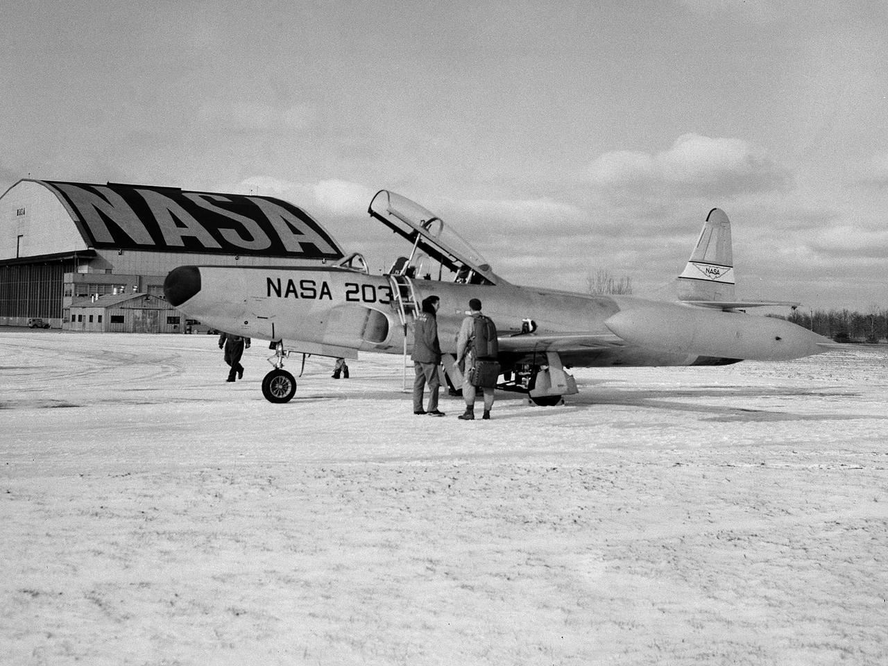
A Lockheed F-94B Starfire on the hangar apron at the National Aeronautics and Space Administration (NASA) Lewis Research Center in Cleveland, Ohio. The Air Force contracted Lockheed in November 1948 to create the new F-94s fighters. The first test flight occurred only months later in April 1949. This quick turnaround was due to the fact that the F-94 was based largely on the TF-80 fighter and constructed with parts from the P-80, including its two General Electric I-40 turbojet engines. The F-94Bs entered the Korean War in late 1951, but were initially prevented from flying over enemy territory due to fear that their fire control system would be copied by the enemy if an F-94B went down. The Starfire went on to perform scores of missions escorting B-29 and B-26 bombers deep into enemy territory and acting as interceptors against enemy fighters. In mid-1954 the F-94s were retired from active military service. Lewis acquired the F-94B Starfire in April 1956. At the time, the aircraft industry was preparing for the first use of jet engines for commercial aviation. The amount of noise generated by the engines was a major obstacle. Lewis undertook an extensive program to understand the causes of the noise and develop methods for reducing it. This program included the study of aerodynamic sound at high speed and altitude using the F-94B.
The Fan Noise Test Facility built at the Lewis Research Center to obtain far-field noise data for the National Aeronautics and Space Administration (NASA) and General Electric Quiet Engine Program. The engine incorporated existing noise reduction methods into an engine of similar power to those that propelled the Boeing 707 or McDonnell-Douglas DC-8 airliner. The new the low-bypass ratio turbofan engines of the 1960s were inherently quieter than their turbojet counterparts, researchers had a better grasp of the noise generation problem, and new acoustic technologies had emerged. Lewis contracted General Electric in 1969 to build and aerodynamically test three experimental engines with 72-inch diameter fans. The engines were then brought to Lewis and tested with an acoustically treated nacelle. This Fan Noise Test Facility was built off of the 10- by 10-Foot Supersonic Wind Tunnel’s Main Compressor and Drive Building. Lewis researchers were able to isolate the fan’s noise during these initial tests by removing the core of the engine. The Lewis test rig drove engines to takeoff tip speeds of 1160 feet per second. The facility was later used to test a series of full-scale model fans and fan noise suppressors to be used with the quiet engine. NASA researchers predicted low-speed single-stage fans without inlet guide vanes and with large spacing between rotors and stators would be quieter. General Electric modified a TF39 turbofan engine by removing the the outer protion of the fan and spacing the blade rows of the inner portion. The tests revealed that the untreated version of the engine generated less noise than was anticipated, and the acoustically treated nacelle substantially reduced engine noise.
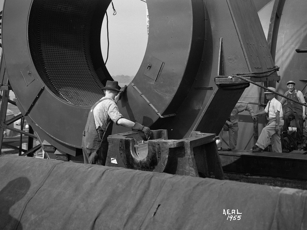
New wooden fan blades being prepared for installation in the Altitude Wind Tunnel at the National Advisory Committee for Aeronautics (NACA) Lewis Flight Propulsion Laboratory. The facility underwent a major upgrade in 1951 to increase its operating capacities in order to handle the new, more powerful turbojet engines being manufactured in the 1950s. The fan blades were prepared in the shop area, seen in this photograph, before being lowered through a hole in the tunnel and attached to the drive shaft. A new drive bearing and tail faring were also installed on the fan as part of this rehab project. A 12-bladed 31-foot-diameter spruce wood fan generated the 300 to 500 mile-per-hour airflow through the tunnel. An 18,000-horsepower General Electric induction motor located in the rear corner of the Exhauster Building drove the fan at 410 revolutions per minute. An extension shaft, sealed in the tunnel’s shell with flexible couplings that allowed for the movement of the shell, connected the motor to the fan. A bronze screen secured to the turning vanes protected the fan against damage from any engine parts sailing through the tunnel. Despite this screen the blades did become worn or cracked over time and had to be replaced.
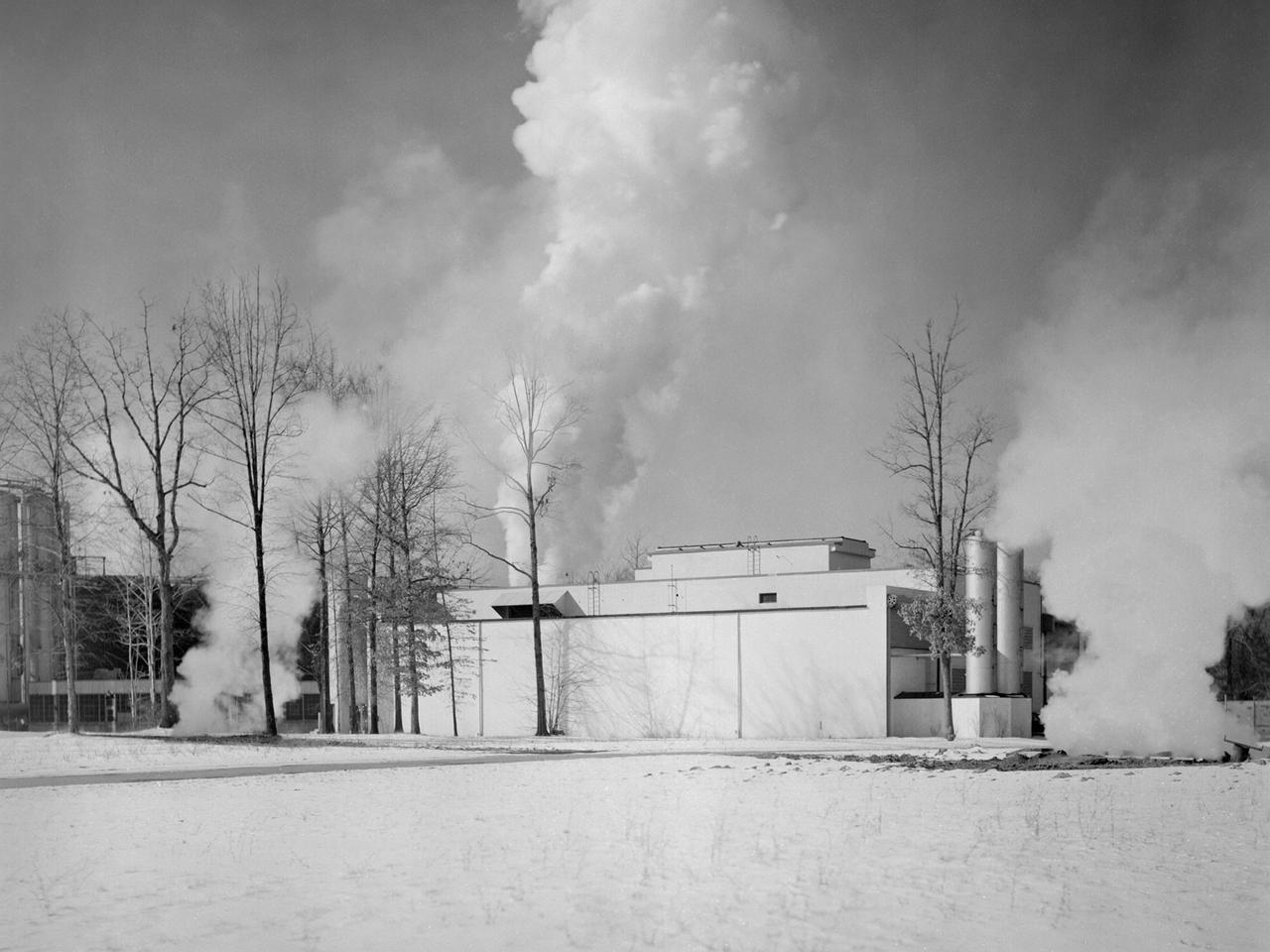
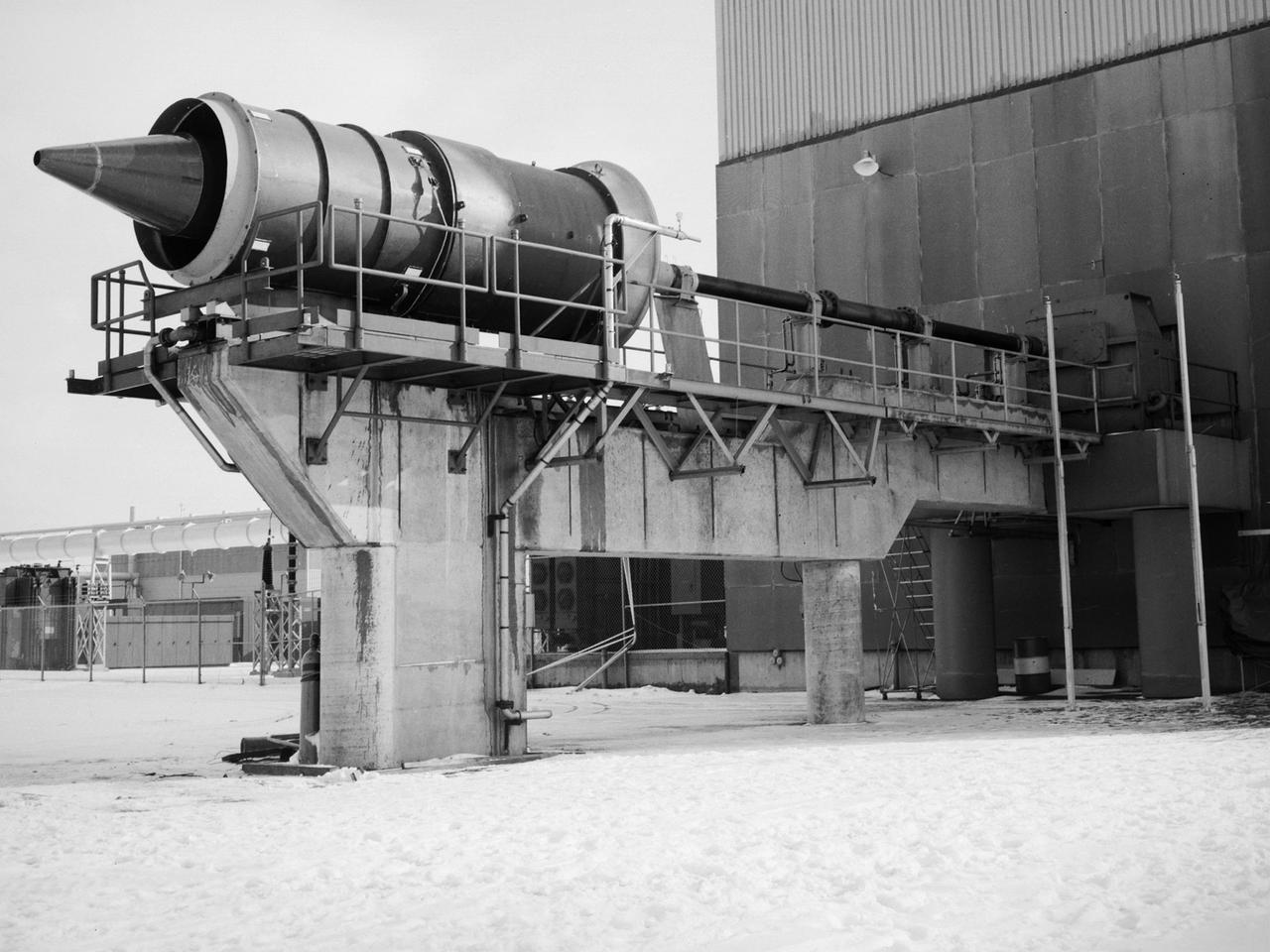
The Engine Propeller Research Building, referred to as the Prop House, emits steam from its acoustic silencers at the National Advisory Committee for Aeronautics (NACA) Lewis Flight Propulsion Laboratory. In 1942 the Prop House became the first completed test facility at the new NACA laboratory in Cleveland, Ohio. It contained four test cells designed to study large reciprocating engines. After World War II, the facility was modified to study turbojet engines. Two of the test cells were divided into smaller test chambers, resulting in a total of six engine stands. During this period the NACA Lewis Materials and Thermodynamics Division used four of the test cells to investigate jet engines constructed with alloys and other high temperature materials. The researchers operated the engines at higher temperatures to study stress, fatigue, rupture, and thermal shock. The Compressor and Turbine Division utilized another test cell to study a NACA-designed compressor installed on a full-scale engine. This design sought to increase engine thrust by increasing its airflow capacity. The higher stage pressure ratio resulted in a reduction of the number of required compressor stages. The last test cell was used at the time by the Engine Research Division to study the effect of high inlet densities on a jet engine. Within a couple years of this photograph the Prop House was significantly altered again. By 1960 the facility was renamed the Electric Propulsion Research Building to better describe its new role in electric propulsion.
One of the two altitude simulating-test chambers in Engine Research Building at the National Advisory Committee for Aeronautics (NACA) Lewis Flight Propulsion Laboratory. The two chambers were collectively referred to as the Four Burner Area. NACA Lewis’ Altitude Wind Tunnel was the nation’s first major facility used for testing full-scale engines in conditions that realistically simulated actual flight. The wind tunnel was such a success in the mid-1940s that there was a backlog of engines waiting to be tested. The Four Burner chambers were quickly built in 1946 and 1947 to ease the Altitude Wind Tunnel’s congested schedule. The Four Burner Area was located in the southwest wing of the massive Engine Research Building, across the road from the Altitude Wind Tunnel. The two chambers were 10 feet in diameter and 60 feet long. The refrigeration equipment produced the temperatures and the exhauster equipment created the low pressures present at altitudes up to 60,000 feet. In 1947 the Rolls Royce Nene was the first engine tested in the new facility. The mechanic in this photograph is installing a General Electric J-35 engine. Over the next ten years, a variety of studies were conducted using the General Electric J-47 and Wright Aeronautical J-65 turbojets. The two test cells were occasionally used for rocket engines between 1957 and 1959, but other facilities were better suited to the rocket engine testing. The Four Burner Area was shutdown in 1959. After years of inactivity, the facility was removed from the Engine Research Building in late 1973 in order to create the High Temperature and Pressure Combustor Test Facility.
A General Electric TG-100A seen from the rear in the test section of the Altitude Wind Tunnel at the National Advisory Committee for Aeronautics (NACA) Lewis Flight Propulsion Laboratory in Cleveland, Ohio. The Altitude Wind Tunnel was used to study almost every model of US turbojet that emerged in the 1940s, as well as some ramjets and turboprops. In the early 1940s the military was interested in an engine that would use less fuel than the early jets but would keep up with them performance-wise. Turboprops seemed like a plausible solution. They could move a large volume of air and thus required less engine speed and less fuel. Researchers at General Electric’s plant in Schenectady, New York worked on the turboprop for several years in the 1930s. They received an army contract in 1941 to design a turboprop engine using an axial-flow compressor. The result was the 14-stage TG-100, the nation's first turboprop aircraft engine. Development of the engine was slow, however, and the military asked NACA Lewis to analyze the engine’s performance. The TG-100A was tested in the Altitude Wind Tunnel and it was determined that the compressors, combustion chamber, and turbine were impervious to changes in altitude. The researchers also established the optimal engine speed and propeller angle at simulated altitudes up to 35,000 feet. Despite these findings, development of the TG-100 was cancelled in May 1947. Twenty-eight of the engines were produced, but they were never incorporated into production aircraft.
A technician at the National Advisory Committee for Aeronautics (NACA) Lewis Flight Propulsion Laboratory cleans the pitot tube on a 16-inch diameter ramjet in the 8- by 6-Foot Supersonic Wind Tunnel. Pitot tubes are a measurement device used to determine the flow velocity at a specific location in the air stream, not the average velocity of the entire wind stream. NACA Lewis was in the midst of a multi-year program to determine the feasibility of ramjets and design improvements that could be employed for all models. The advantage of the ramjet was its ability to process large volumes of combustion air, resulting in the burning of fuel at the optimal stoichiometric temperatures. This was not possible with turbojets. The higher the Mach number, the more efficient the ramjet operated. The 8- by 6 Supersonic Wind Tunnel had been in operation for just over one year when this photograph was taken. The facility was the NACA’s largest supersonic tunnel and the only facility capable of running an engine at supersonic speeds. The 8- by 6 tunnel was also equipped with a Schlieren camera system that captured the air flow gradient as it passes over the test setup. The ramjet tests in the 8- by 6 tunnel complemented the NACA Lewis investigations using aircraft, the Altitude Wind Tunnel and smaller supersonic tunnels. Researchers studied the ramjet’s performance at different speeds and varying angles -of -attack.
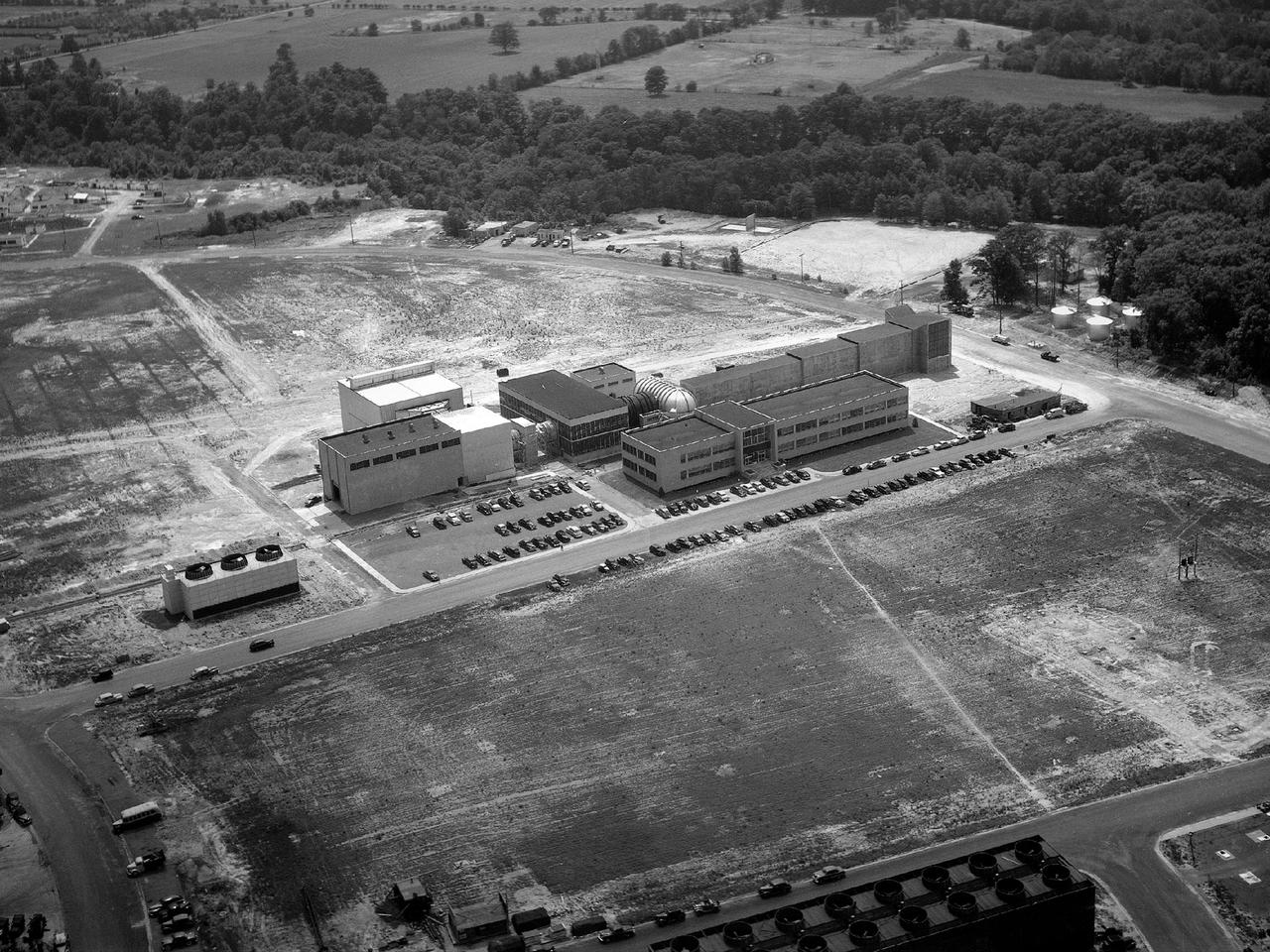
Aerial view of the 8- by 6-Foot Supersonic Wind Tunnel in its original configuration at the National Advisory Committee for Aeronautics (NACA) Lewis Flight Propulsion Laboratory. The 8- by 6 was the laboratory’s first large supersonic wind tunnel. It was also the NACA’s most powerful supersonic tunnel, and its first facility capable of running an engine at supersonic speeds. The 8- by 6-foot tunnel has been used to study inlets and exit nozzles, fuel injectors, flameholders, exit nozzles, and controls on ramjet and turbojet propulsion systems. The 8- by 6 was originally an open-throat and non-return tunnel. This meant that the supersonic air flow was blown through the test section and out the other end into the atmosphere. In this photograph, the three drive motors in the structure at the left supplied power to the seven-stage axial-flow compressor in the light-colored structure. The air flow passed through flexible walls which were bent to create the desired speed. The test article was located in the 8- by 6-foot stainless steel test section located inside the steel pressure chamber at the center of this photograph. The tunnel dimensions were then gradually increased to slow the air flow before it exited into the atmosphere. The large two-story building in front of the tunnel was used as office space for the researchers.
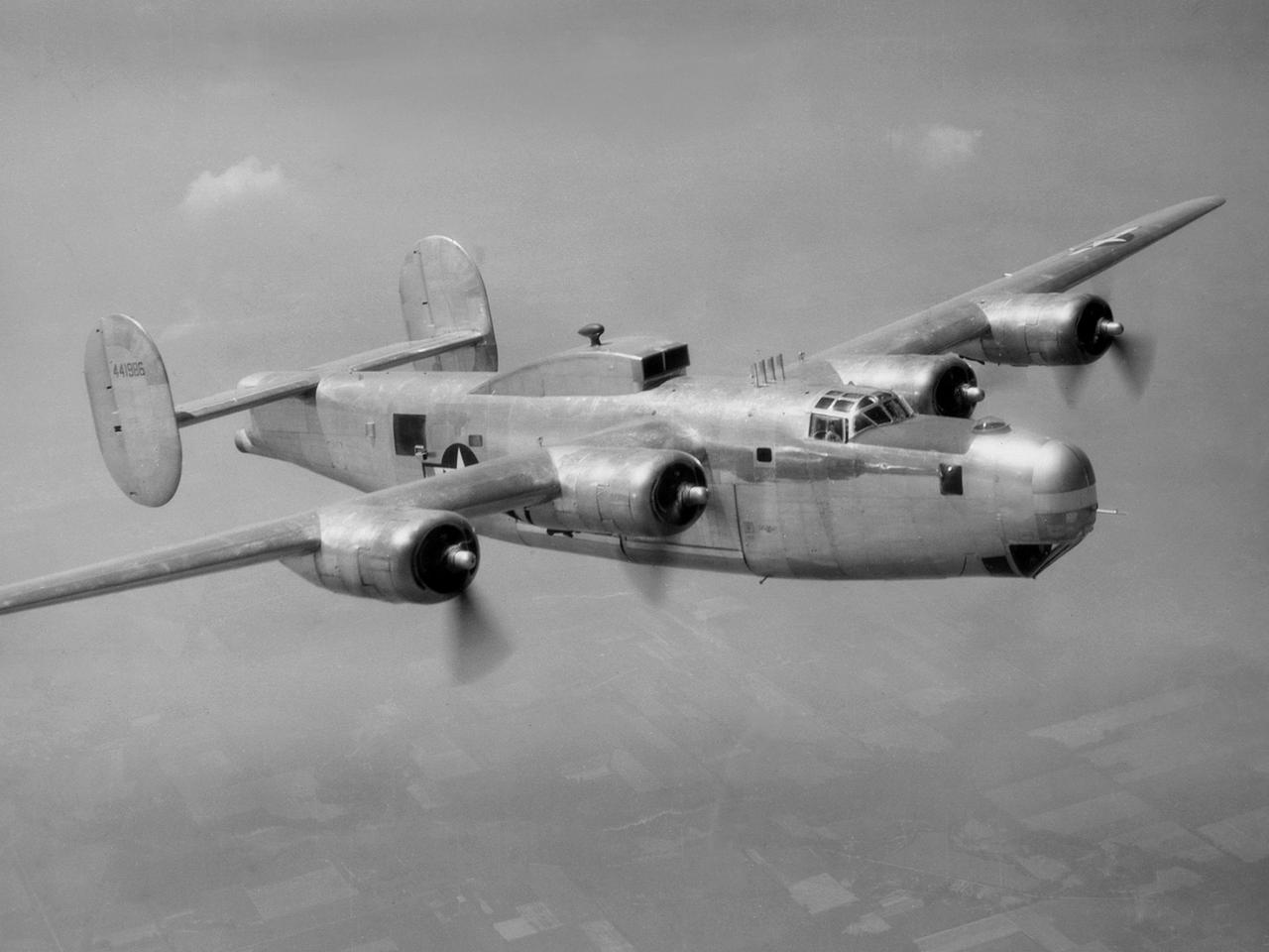
A Consolidated B-25M Liberator modified for icing research by the National Advisory Committee for Aeronautics (NACA) Lewis Flight Propulsion Laboratory. NACA Lewis performed a limited amount of icing research during World War II, but the program expanded significantly in 1946. The accumulation of ice on aircraft was a continual problem. The ice formations could result in extra weight, aerodynamic penalties, and blockage engine inlets. Although the Lewis icing researchers utilized numerous aircraft, the program’s two workhorses were the B-24M Liberator, seen here, and a North American XB-25E Mitchell. The Consolidated Aircraft Company created the four-engine bomber in the early 1940s. During World War II the bomber was employed on long-duration bombing missions in both Europe and the Pacific. Production of the B-24M version did not begin until October 1944 with the end of the war in Europe approaching. This resulted in scores of unneeded bombers when hostilities ended. This B-24M arrived at the NACA Lewis laboratory in November 1945. At Lewis the B-24M was repeatedly modified to study ice accretion on aircraft components. Researchers analyzed different anti-icing and deicing strategies and gathered statistical ice measurement data. The B-24M was also used to study ice buildup on jet engines. A General Electric I-16 engine was installed in the aircraft’s waist compartment with an air scoop on the top of the aircraft to duct air to the engine. Water spray nozzles inside the aircraft were employed to simulate icing conditions at the turbojet’s inlet.
The secret test of the Bell YP–59A Airacomet in the spring of 1944 was the first investigation in the National Advisory Committee for Aeronautics (NACA) Aircraft Engine Research Laboratory’s new Altitude Wind Tunnel (AWT). The Airacomet, powered by two General Electric I–A centrifugal turbojets, was the first US jet aircraft. The Airacomet’s 290-miles per hour speed, however, was dwarfed by the German Messerschmitt Me-262 Schwalbe’s 540 miles per hour. In 1941 and 1942 General Electric built the first US jet engines based on technical drawings from British engineer Frank Whittle. Bell Aircraft was contracted to produce an airframe to incorporate the new engines. The result was the Bell XP–59A Airacomet. The aircraft made its first flight over Muroc Lake, California, on October 2, 1942. The aircraft continued to struggle over the next year and the NACA was asked to test it in the new AWT. A Bell YP–59A was flown from the Bell plant in Buffalo to Cleveland by Bob Stanley, who had piloted the first successful flight of the XP–59A at Muroc in 1942. The wing tips and tail were cut from the aircraft so that it would fit into the AWT’s test section. The study first analyzed the engines in their original configuration and then implemented a boundary layer removal duct, a new nacelle inlet, and new cooling seals. Tests of the modified version showed that the improved airflow distribution increased the I–16’s performance by 25 percent. Despite the improved speed, the aircraft was not stable enough to be used in combat, and the design was soon abandoned.
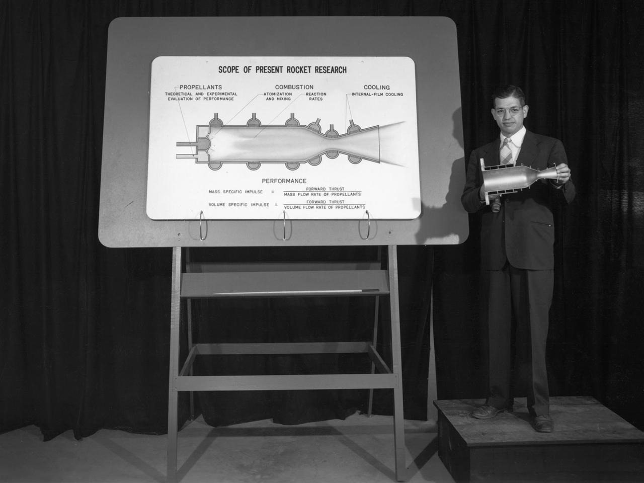
Researcher John Sloop briefs visitors on his latest rocket engine research during the 1947 Inspection at the National Advisory Committee for Aeronautics (NACA) Lewis Flight Propulsion Laboratory. The NACA had been hosting annual Aircraft Engineering Conferences, better known as Inspections, since 1926. Individuals from the manufacturing industry, military, and university settings were invited to tour the NACA laboratories. There were a series of stops on the tour, mostly at test facilities, where researchers would brief the group on the latest efforts in their particular field. The Inspections grew in size and scope over the years and by the mid-1940s required multiple days. The three-day 1947 Inspection was the first time the event was held at NACA Lewis. Over 800 scientists, industrialists, and military leaders attended the three-day event. Talks were given at the Altitude Wind Tunnel, Four Burner Area, Engine Research Building, and other facilities. An array of topics were discussed, including full-scale engine testing, ramjets, axial-flow compressors, turbojets, fuels, icing, and materials. The NACA Lewis staff and their families were able to view the same presentations after the Inspection was over. Sloop, a researcher in the Fuels and Thermodynamics Division, briefed visitors on NACA Lewis’ early research in rocket engine propellants, combustion, and cooling. This early NACA Lewis work led to the development of liquid hydrogen as a viable propellant in the late 1950s.
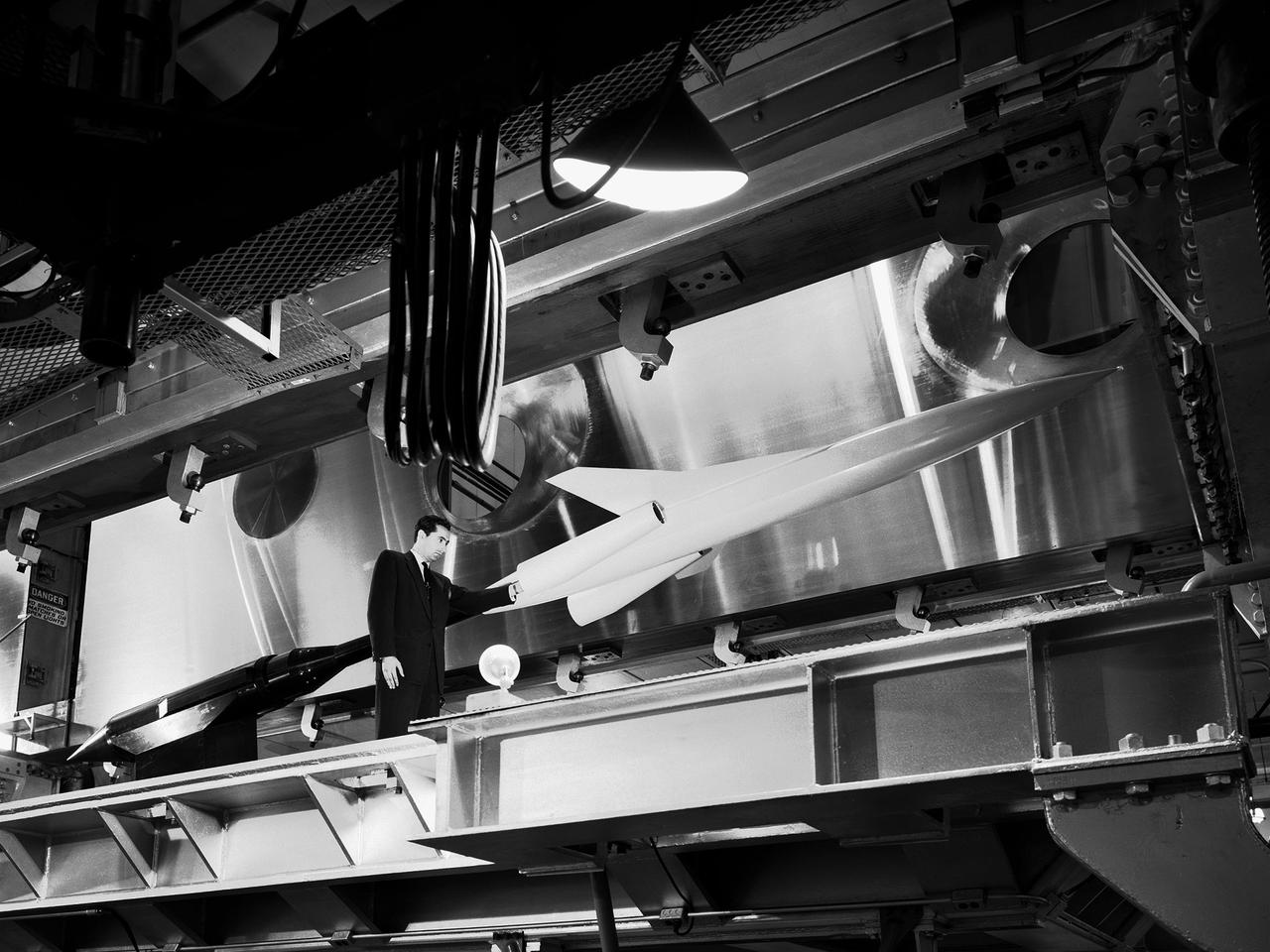
A researcher examines a model being installed in the test section of the 10- by 10-Foot Supersonic Wind Tunnel during the 1957 Inspection of the National Advisory Committee for Aeronautics (NACA) Lewis Flight Propulsion Laboratory. The NACA held its annual Inspection at one of its three research laboratories. Representatives from the military, aeronautical industry, universities, and the press were invited to the laboratory to be briefed on the NACA’s latest research efforts and tour the state- of- the- art test facilities. Over 1700 people visited the NACA Lewis in Cleveland, Ohio during the October 7 - 10, 1957 Inspection. NACA researchers Leonard Obery, seen here, James Connors, Leonard, Stitt, David Bowditch gave presentations on high Mach number turbojets at the 10- by 10 tunnel. It had been only 15 years since a jet aircraft had first flown in the US. Since then the sound barrier had been broken and speeds of Mach 2.5 had been achieved. In the late 1950s NACA researchers sought to create an engine that could achieve Mach 4. This type of engine would require an extremely long inlet and nozzle which would have to be capable of adjusting their diameter for different speeds. A Mach 4 engine would require new composite materials to withstand the severe conditions, modified airframes to hold the longer engines, and high temperature seals and lubricants. The 10- by 10-foot tunnel, which had only been in operation for a year and a half, would play a critical role in these studies. NACA researchers at other facilities discussed high energy aircraft fuels and rocket propellants, aircraft noise reduction, hypersonic flight, nuclear propulsion, and high temperature materials.
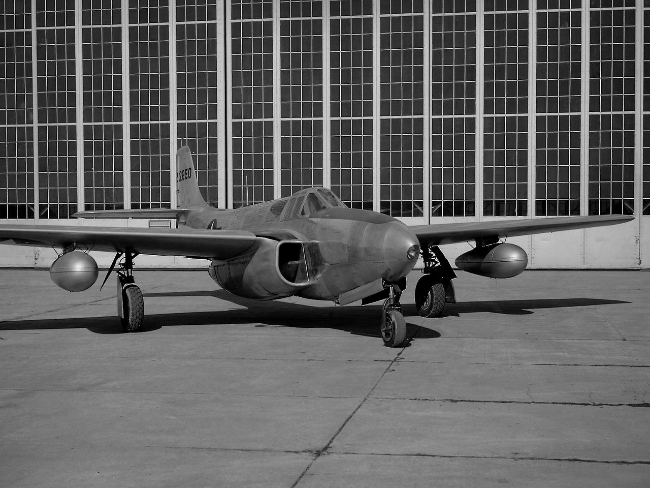
A Bell P-59B Airacomet sits beside the hangar at the National Advisory Committee for Aeronautics (NACA) Lewis Flight Propulsion Laboratory. In 1942 the Bell XP-59A Airacomet became the first jet aircraft in the US. The Airacomet incorporated centrifugal turbojet engines that were based on British plans secretly brought to the US in 1941. A Bell test pilot flew the XP-59A for the first time at Muroc Lake, California in October 1942. The General Electric I-16 engines proved to be problematic. In an effort to increase the engine performance, an Airacomet was secretly brought to Cleveland in early 1944 for testing in the Altitude Wind Tunnel. A series of tunnel investigations in February and March resulted in a 25-percent increase in the I-16 engine’s performance. Nonetheless, Bell’s 66 Airacomets never made it into combat. A second, slightly improved Airacomet, a P-59B, was transferred to NACA Lewis just after the war in September 1945. The P-59B was used over the next three years to study general jet thrust performance and thrust augmentation devices such as afterburners and water/alcohol injection. The P-59B flights determined the proper alcohol and water mixture and injection rate to produce a 21-percent increase in thrust. Since the extra boost would be most useful for takeoffs, a series of ground-based tests with the aircraft ensued. It was determined that the runway length for takeoffs could be reduced by as much as 15 percent. The P-59B used for the tests is now on display at the Air Force Museum at Wright Patterson.
A researcher at the National Advisory Committee for Aeronautics (NACA) Lewis Flight Propulsion Laboratory checks the setup of a RJM-2 ramjet model in the test section of the 8- by 6-Foot Supersonic Wind Tunnel. The 8- by 6 was not only the laboratory’s first large supersonic wind tunnel, but it was also the NACA’s first facility capable of testing an operating engine at supersonic speeds. The 8- by 6-foot tunnel has been used to study engine inlets, fuel injectors, flameholders, exit nozzles, and controls on ramjet and turbojet propulsion systems. The 8-foot wide and 6-foot tall test section consisted of 1-inch thick steel plates with hatches on the floor and ceiling to facilitate the installation of the test article. The two windows seen on the right wall allowed photographic equipment to be set up. The test section was modified in 1956 to accommodate transonic research. NACA engineers drilled 4,700 holes into the test section walls to reduce transonic pressure disturbances and shock waves. NACA Lewis undertook an extensive research program on ramjets in the 1940s using several of its facilities. Ramjets provide a very simple source of propulsion. They are basically a tube which ingests high speed air, ignites it, and then expels the heated air at a significantly higher velocity. Ramjets are extremely efficient and powerful but can only operate at high speeds. Therefore, they require a booster rocket or aircraft drop to accelerate them to high speeds before they can operate.
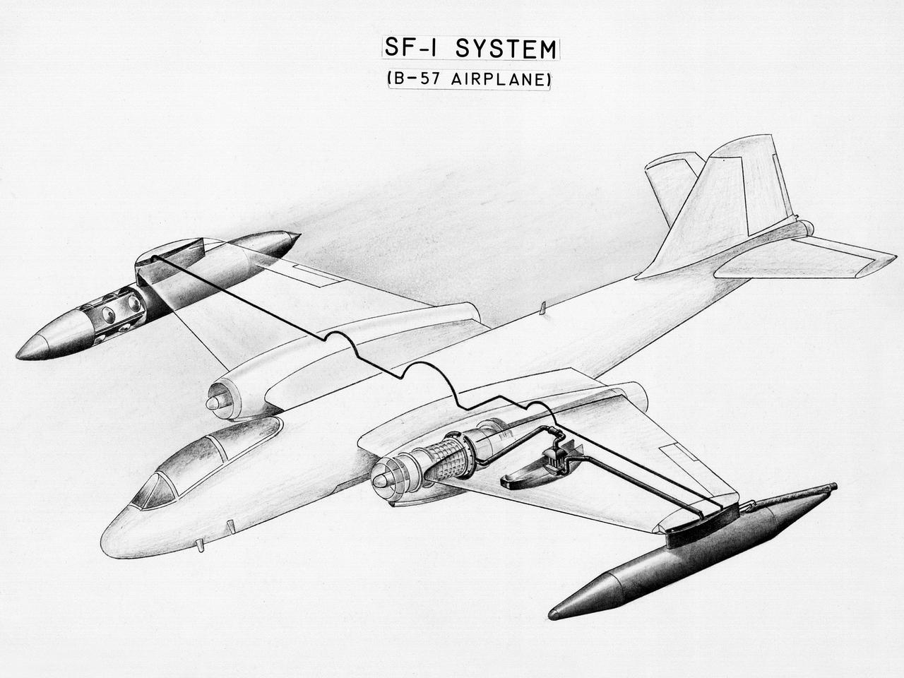
This diagram shows a hydrogen fuel system designed by researchers at the National Advisory Committee for Aeronautics (NACA) Lewis Flight Propulsion Laboratory and installed on a Martin B-57B Canberra aircraft. Lewis researchers accelerated their studies of high energy propellants in the early 1950s. In late 1954, Lewis researchers studied the combustion characteristics of gaseous hydrogen in a turbojet combustor. It was found that the hydrogen provided a very high efficiency. Almost immediately thereafter, Associate Director Abe Silverstein became focused on the possibilities of hydrogen for aircraft propulsion. That fall, Silverstein secured a contract to work with the air force to examine the practicality of liquid hydrogen aircraft. A B-57B Canberra was obtained by the air force especially for this project, referred to as Project Bee. The aircraft was powered by two Wright J65 engines, one of which was modified so that it could be operated using either traditional or liquid hydrogen propellants. The engine and its liquid hydrogen fuel system were tested extensively in the Altitude Wind Tunnel and the Four Burner Area test cells in 1955 and 1956. A B-57B flight program was planned to test the system on an actual aircraft. The aircraft would take off using jet fuel, switch to liquid hydrogen while over Lake Erie, then after burning the hydrogen supply switch back to jet fuel for the landing. The third test flight, in February 1957, was a success, and the ensuing B-57B flights remain the only demonstration of hydrogen-powered aircraft.
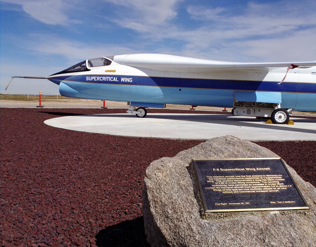
A Vought F-8A Crusader was selected by NASA as the testbed aircraft (designated TF-8A) to install an experimental Supercritical Wing (SCW) in place of the conventional wing. The unique design of the Supercritical Wing reduces the effect of shock waves on the upper surface near Mach 1, which in turn reduces drag. In the photograph the TF-8A Crusader with the Supercritical Wing is shown on static display in front of the NASA Dryden Flight Research Center, Edwards, California. The F-8 SCW aircraft, along with the F-8 Digital Fly-By-Wire aircraft were placed on display on May 27, 1992, at a conference marking the 20th anniversary of the start of the two programs.
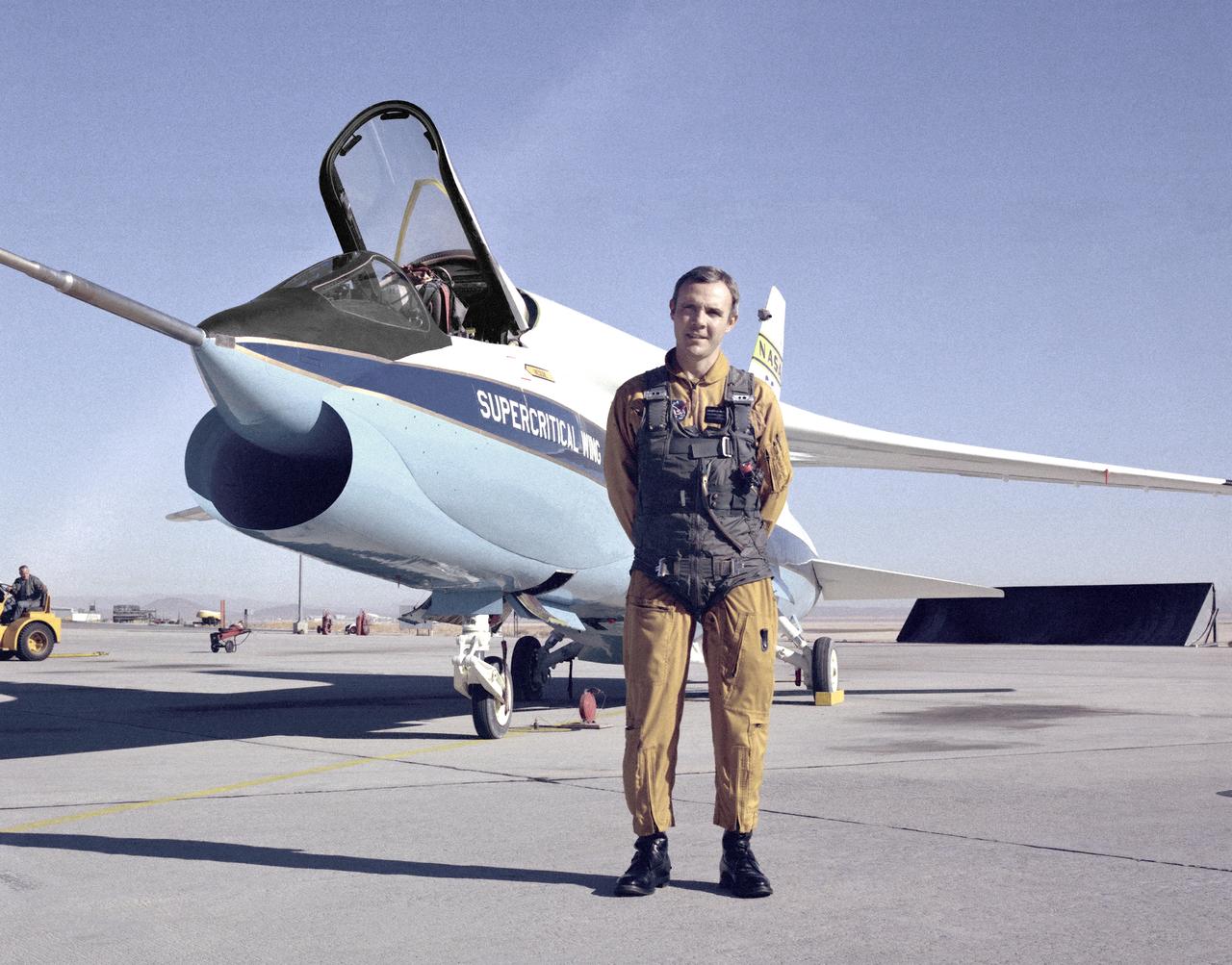
A Vought F-8A Crusader was selected by NASA as the testbed aircraft (designated TF-8A) to install an experimental Supercritical Wing (SCW) in place of the conventional wing. The unique design of the Supercritical Wing reduces the effect of shock waves on the upper surface near Mach 1, which in turn reduces drag. In this photograph the TF-8A Crusader with Supercritical Wing is shown on the ramp with project pilot Tom McMurtry standing beside it. McMurtry received NASA's Exceptional Service Medal for his work on the F-8 SCW aircraft. He also flew the AD-1, F-15 Digital Electronic Engine Control, the KC-130 winglets, the F-8 Digital Fly-By-Wire and other flight research aircraft including the remotely piloted 720 Controlled Impact Demonstration and sub-scale F-15 research projects. In addition, McMurtry was the 747 co-pilot for the Shuttle Approach and Landing Tests and made the last glide flight in the X-24B. McMurtry was Dryden’s Director for Flight Operations from 1986 to 1998, when he became Associate Director for Operations at NASA Dryden. In 1982, McMurtry received the Iven C. Kincheloe Award from the Society of Experimental Test Pilots for his contributions as project pilot on the AD-1 Oblique Wing program. In 1998 he was named as one of the honorees at the Lancaster, Calif., ninth Aerospace Walk of Honor ceremonies. In 1999 he was awarded the NASA Distinguished Service Medal. He retired in 1999 after a distinguished career as pilot and manager at Dryden that began in 1967.
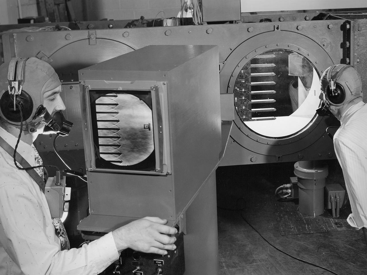
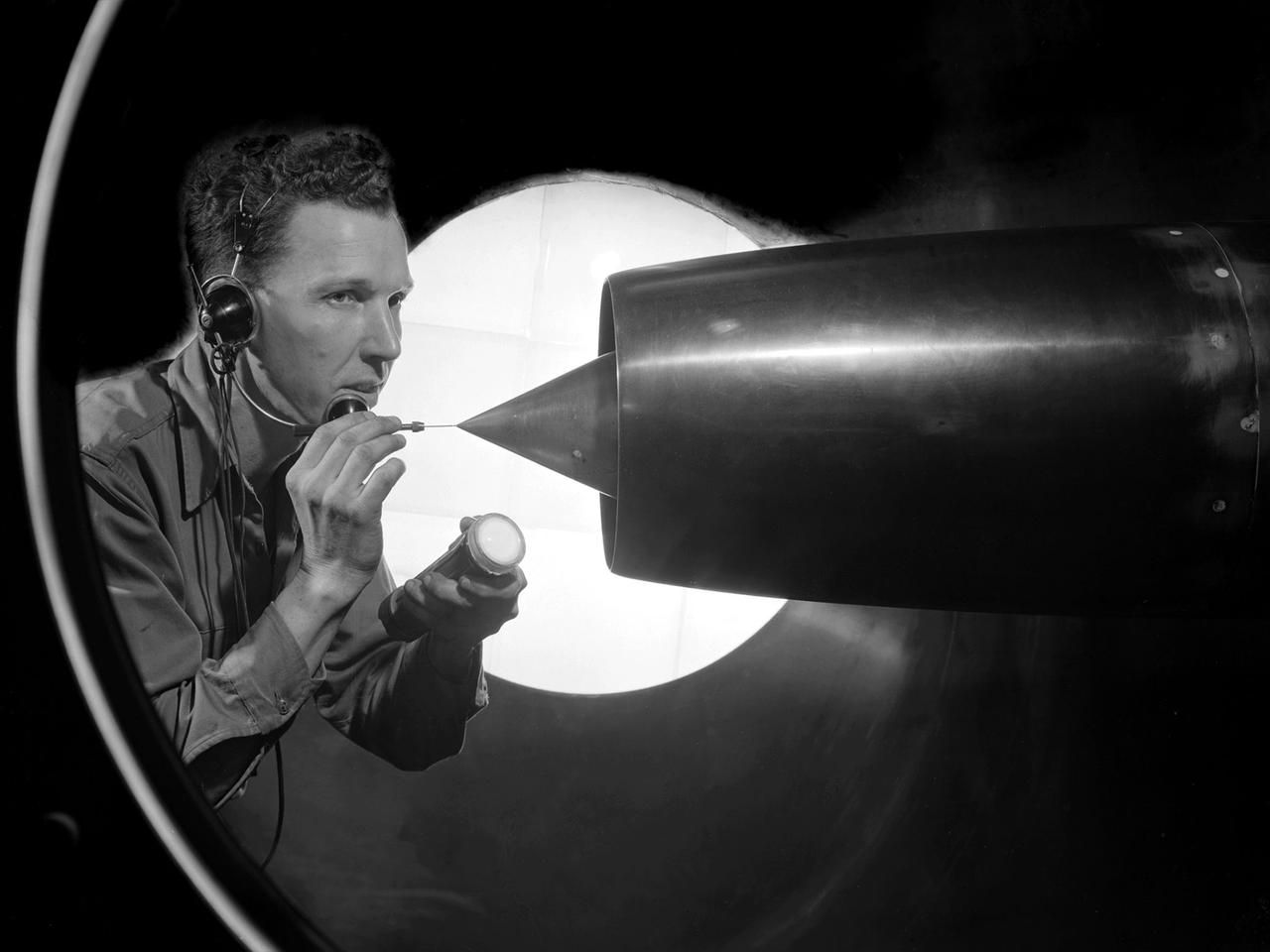
Engineers calibrate one of three small supersonic wind tunnels that were collectively referred to as the “Stack Tunnels” at the National Advisory Committee for Aeronautics (NACA) Lewis Flight Propulsion Laboratory. In late 1945 NACA Lewis reorganized its staff and began constructing a new wave of facilities to address high-speed flight and the turbojet and rocket technologies that emerged during World War II. While design work began on what would eventually become the 8- by 6-Foot Supersonic Wind Tunnel, NACA Lewis quickly built several small supersonic tunnels. These small facilities utilized the Altitude Wind Tunnel’s massive air handling equipment. Three of the small tunnels were built vertically on top of each other and thus were known as the Stack Tunnels. The first of the Stack Tunnels was an 18- by 18-inch tunnel that began operating in August 1945 at speeds up to Mach 1.91. The second tunnel, whose 24- by 24-inch test section is shown here, was added in 1949. It could generate air flows up to Mach 3.96. A third tunnel with an 18- by 18-inch test section began operating in 1951 with speeds up to Mach 3.05. The small tunnels were used until the early 1960s to study the aerodynamic characteristics of supersonic inlets and exits. The technician to the left in this photograph is operating a Schlieren camera to view the air flow dynamics inside the 24- by 24-inch test section. The technician on the right is viewing the pronged test article through the circular window. They are calibrating the tunnel and its equipment to prepare for the initial test runs.
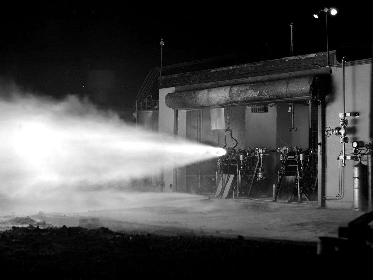
A rocket using high-energy propellant is fired from the Rocket Laboratory at the National Advisory Committee for Aeronautics (NACA) Lewis Flight Propulsion Laboratory. The Rocket Lab was a collection of ten one-story cinderblock test cells located behind earthen barriers at the western edge of the campus. The rocket engines tested there were comparatively small, but the Lewis researchers were able to study different configurations, combustion performance, and injectors and nozzle design. The rockets were generally mounted horizontally and fired, as seen in this photograph of Test Cell No. 22. A group of fuels researchers at Lewis refocused their efforts after World War II in order to explore high energy propellants, combustion, and cooling. Research in these three areas began in 1945 and continued through the 1960s. The group of rocket researches was not elevated to a division branch until 1952. The early NACA Lewis work led to the development of liquid hydrogen as a viable propellant in the late 1950s. Following the 1949 reorganization of the research divisions, the rocket group began working with high-energy propellants such as diborane, pentaborane, and hydrogen. The lightweight fuels offered high levels of energy but were difficult to handle and required large tanks. In late 1954, Lewis researchers studied the combustion characteristics of gaseous hydrogen in a turbojet combustor. Despite poor mixing of the fuel and air, it was found that the hydrogen yielded more than a 90-percent efficiency. Liquid hydrogen became the focus of Lewis researchers for the next 15 years.
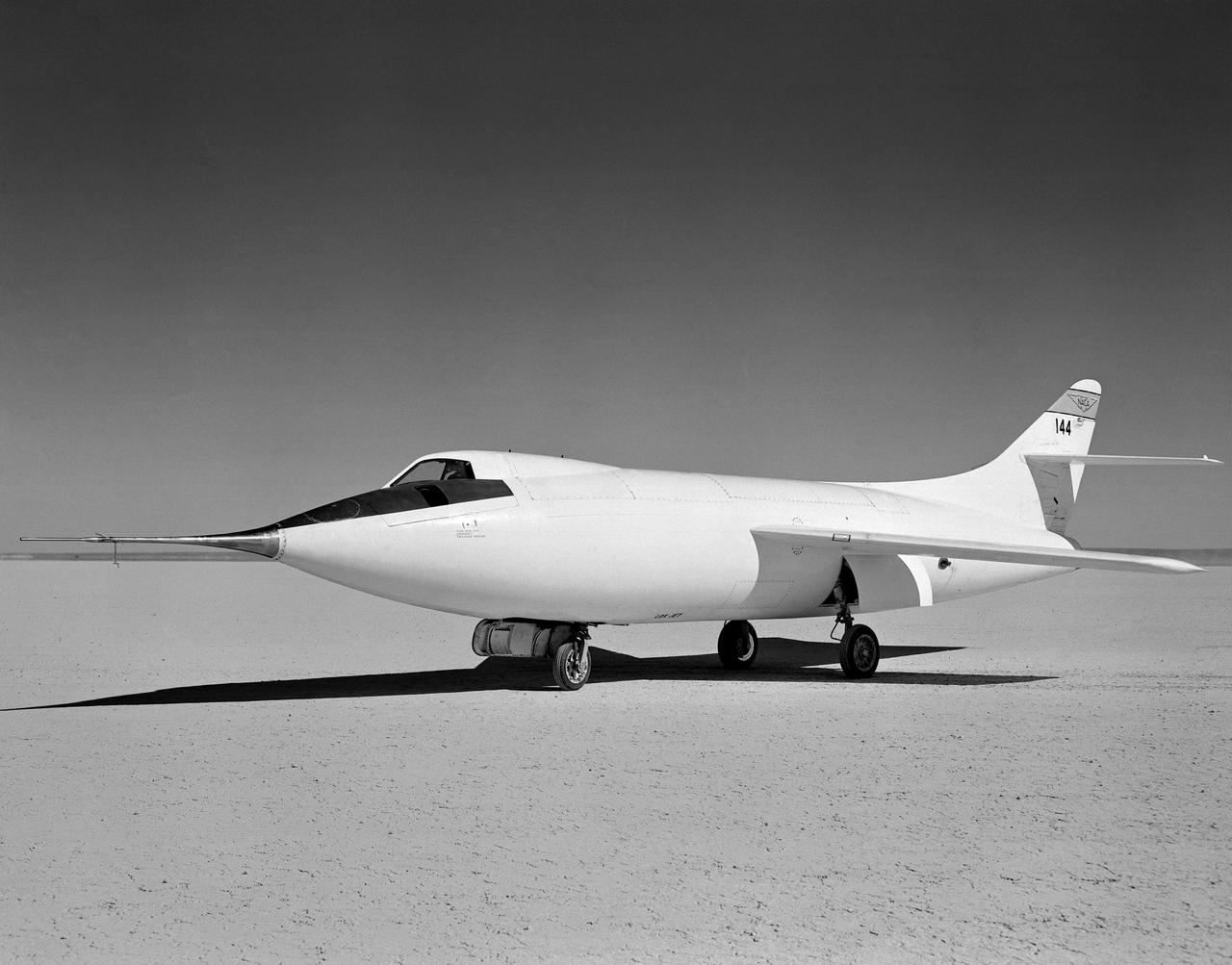
D-558-2 Aircraft on lakebed
D-558-2 being mounted to P2B-1S launch aircraft in hangar.
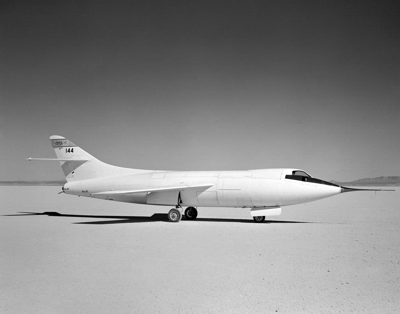
D-558-2 Aircraft on lakebed
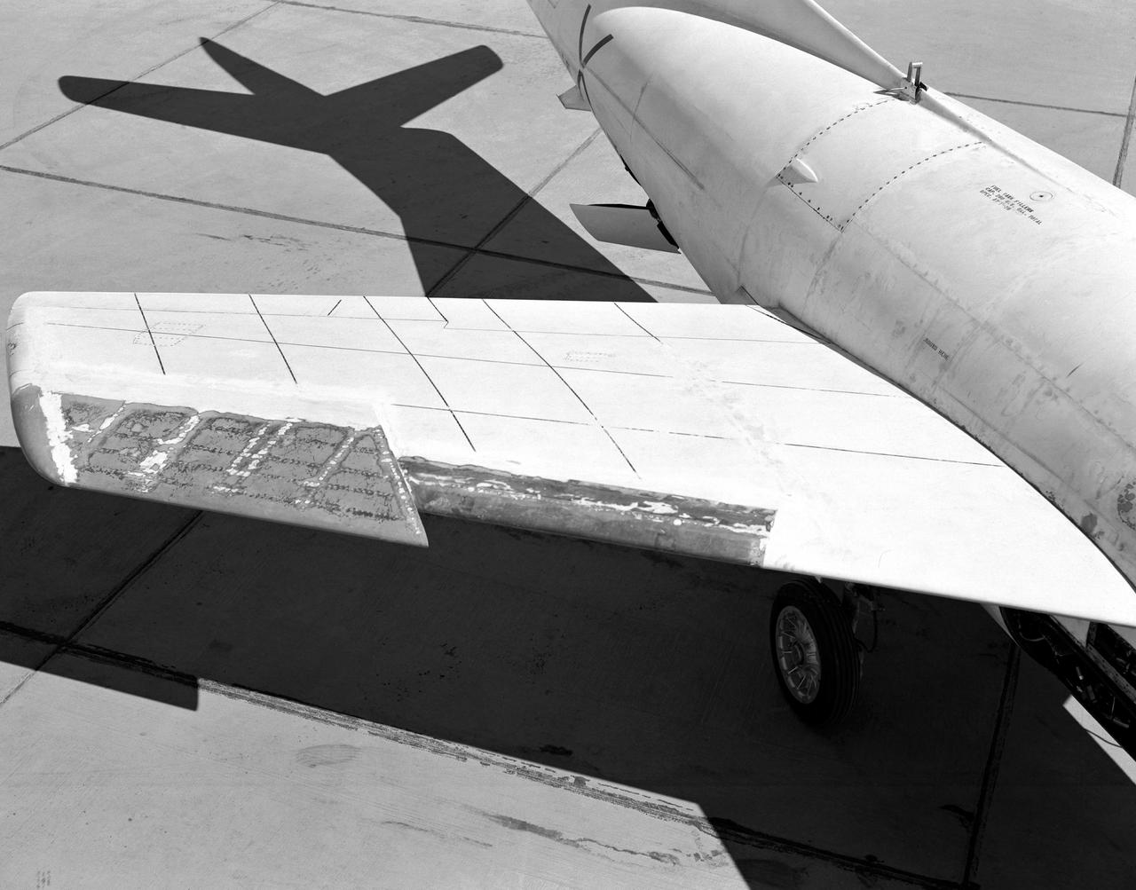
Wing chord extension on D-558-2
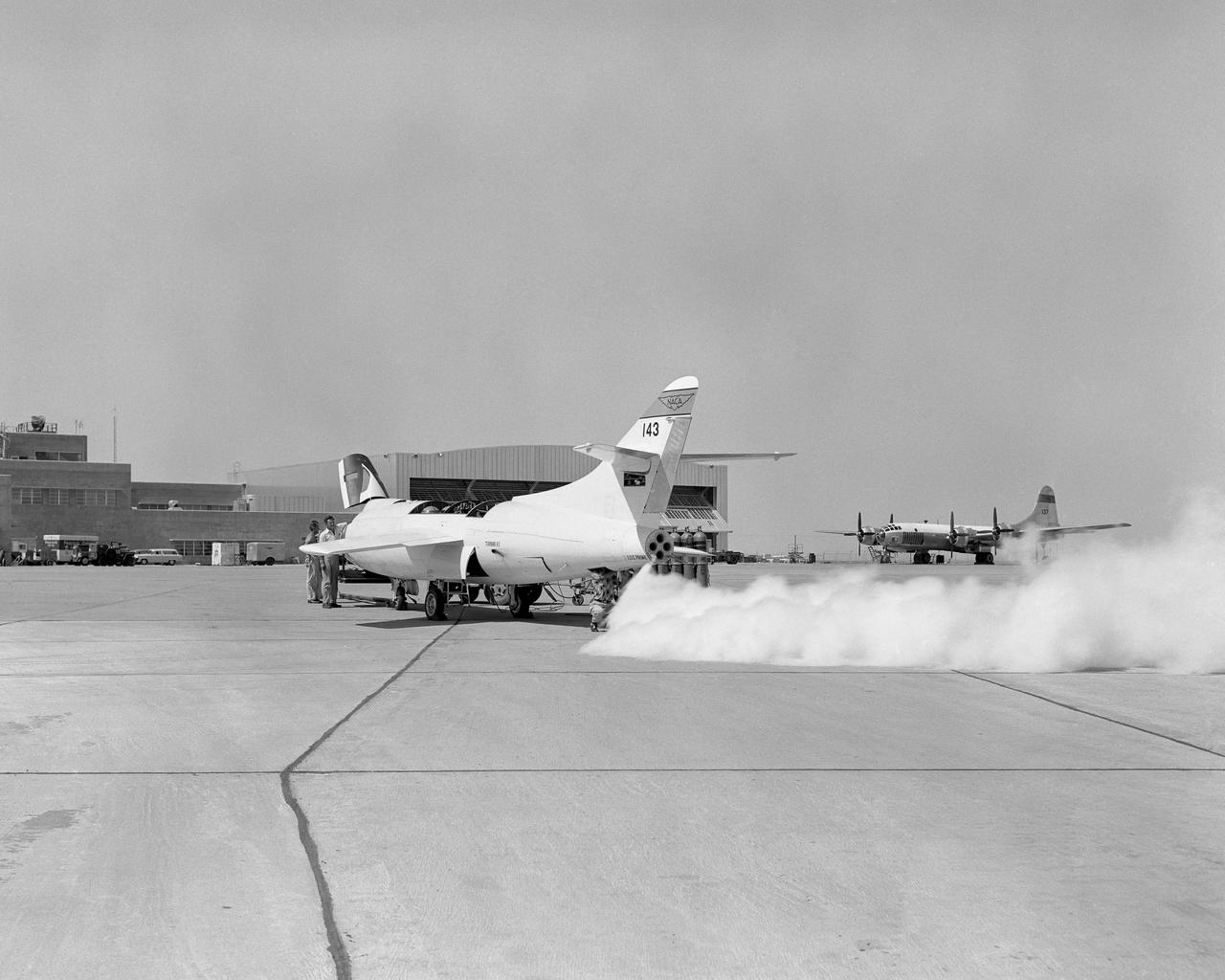
D558-2 #143 LOX jettison with P2BS in background