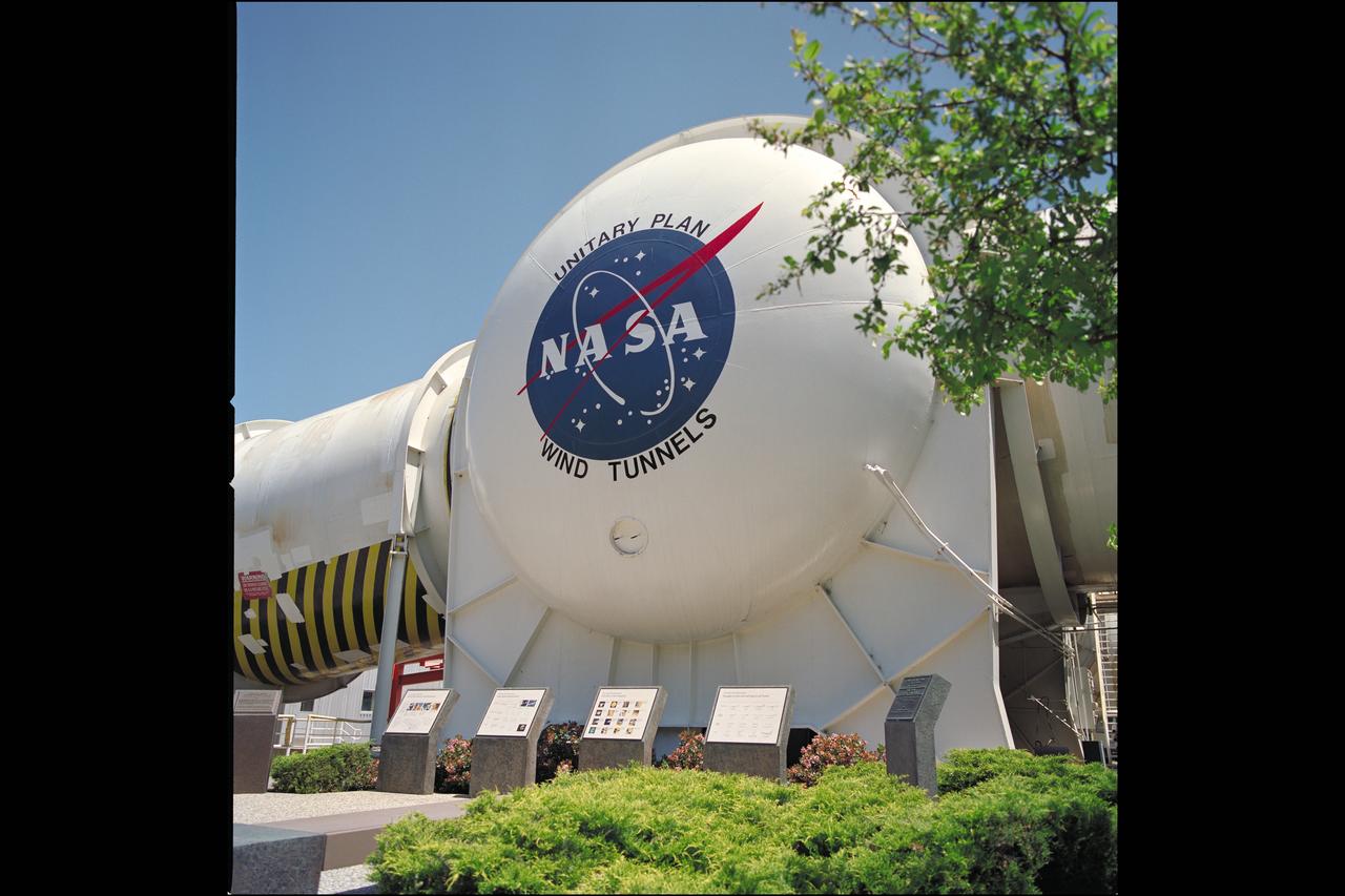
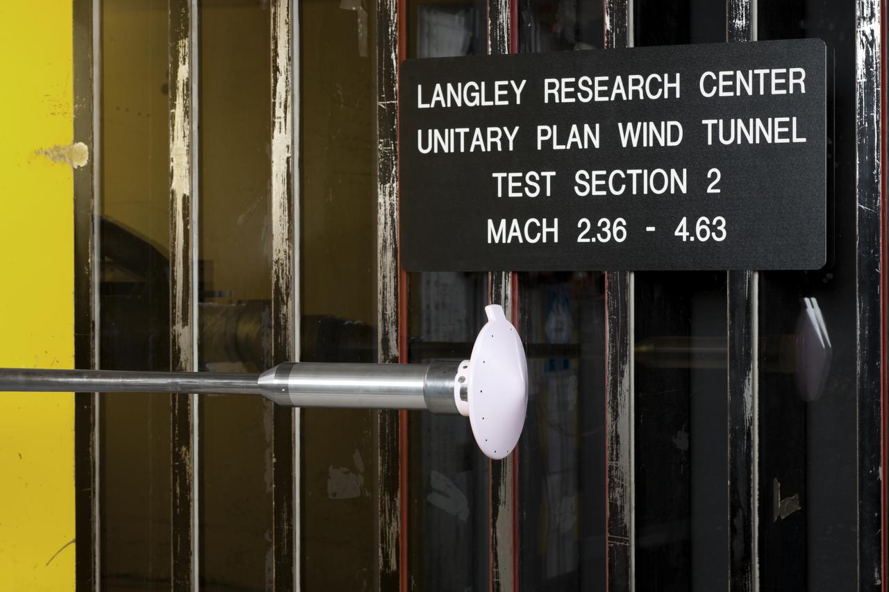
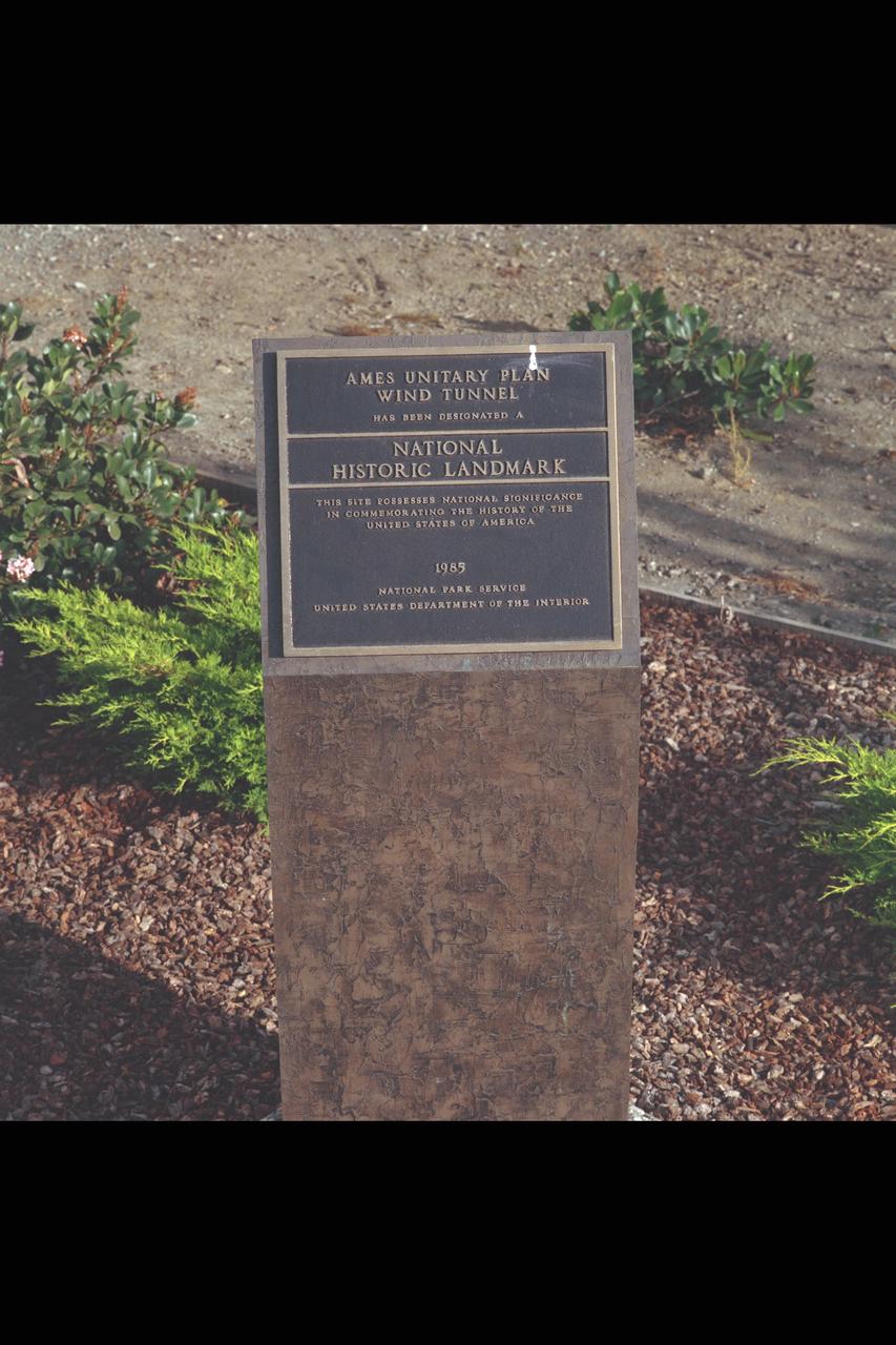
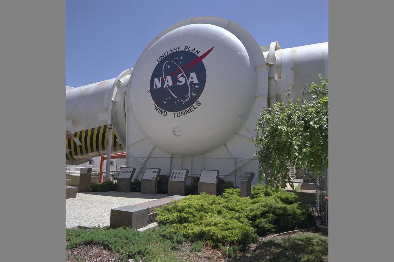
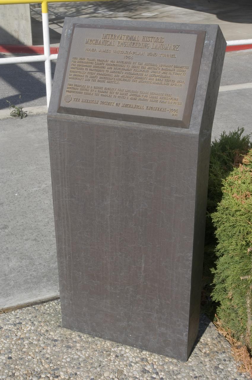
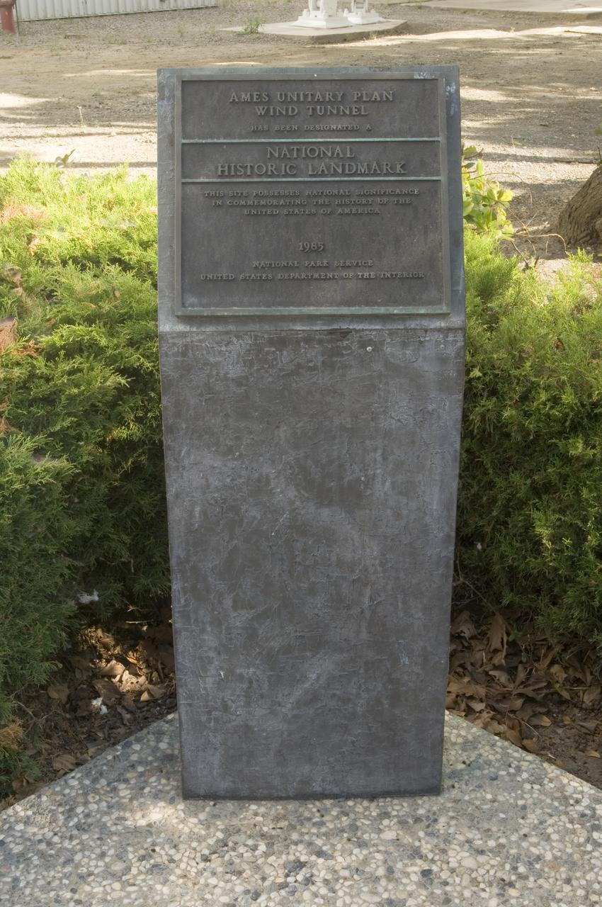
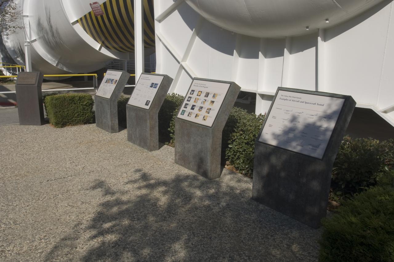
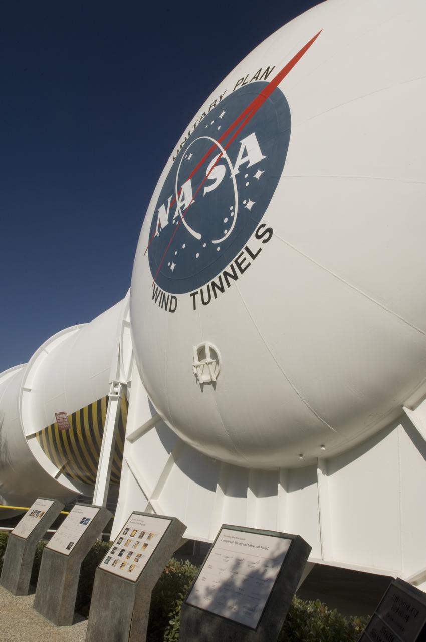
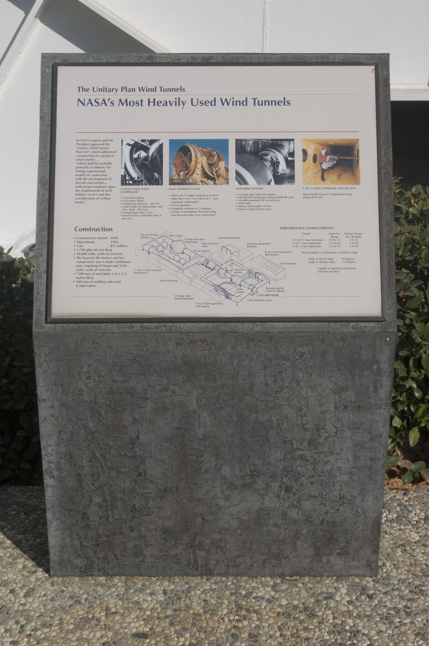
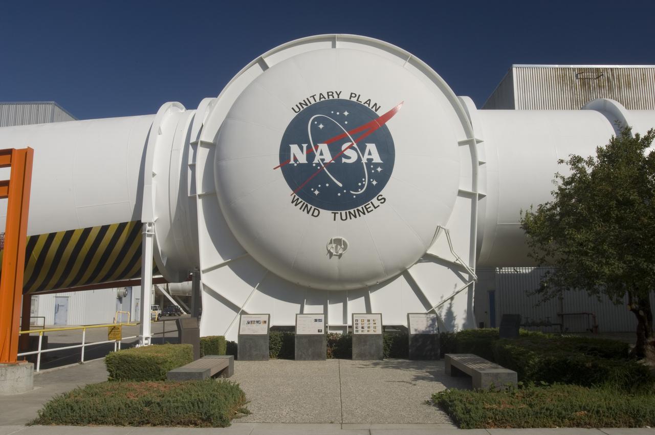
Gemini capsule being tested in Unitary Plan Wind Tunnel.
LRC-1962-B701_P-08679
N-227 Unitary Wind Tunnel Data Control Room: Hardware
ARC-1985-AC85-0443-1
Unitary Wind Tunnel Display
N-227 Unitary Plan Wind Tunnel Modification Project - diffuser & contraction vanes  (image show reflection of photographer on vane)
ARC-1996-AC96-5007-4
N-227 Unitary Plan Wind Tunnel Modification Project - diffuser & contraction vanes
ARC-1996-AC96-5007-1
MD-90 Model in NASA Ames Research Center 11ft. Transonic Wind Tunnel  part of the Unitary Plan Wind Tunnel Complex Test-091-1-11
ARC-1990-AC90-0481-8
N-227 Unitary Plan Wind Tunnel with NASA 'Meatball' insignia over looking the National  Historical Landmark sites' commemorative plaques
ARC-1999-AC99-0101-3
0.4% Scale (SLS) Space Launch System Model Test In NASA LaRC Unitary Plan Wind Tunnel
0.4% Scale (SLS) Space Launch System Model Test In NASA LaRC Uni
0.4% Scale (SLS) Space Launch System Model Test In NASA LaRC Unitary Plan Wind Tunnel
0.4% Scale (SLS) Space Launch System Model Test In NASA LaRC Uni
0.4% Scale (SLS) Space Launch System Model Test In NASA LaRC Unitary Plan Wind Tunnel
0.4% Scale (SLS) Space Launch System Model Test In NASA LaRC Uni
0.4% Scale (SLS) Space Launch System Model Test In NASA LaRC Unitary Plan Wind Tunnel
0.4% Scale (SLS) Space Launch System Model Test In NASA LaRC Uni
0.4% Scale (SLS) Space Launch System Model Test In NASA LaRC Unitary Plan Wind Tunnel
0.4% Scale (SLS) Space Launch System Model Test In NASA LaRC Uni
0.4% Scale (SLS) Space Launch System Model Test In NASA LaRC Unitary Plan Wind Tunnel
0.4% Scale (SLS) Space Launch System Model Test In NASA LaRC Uni
Fig. 68 Unitary Wind Tunnel Display
Martin-Bell Dyna Soar I in Unitary Tunnel
Low-boom Model Mach II in Unitary Tunnel with Christine Darden
Low-boom Model Mach II in Unitary Tunnel
Low-boom Model Mach II in Unitary Tunnel with Christine Darden
Low-boom Model Mach II in Unitary Tunnel
Low-boom Model Mach II in Unitary Tunnel with Christine Darden
Low-boom Model Mach II in Unitary Tunnel
Low-boom Model Mach II in Unitary Tunnel with Christine Darden
Low-boom Model Mach II in Unitary Tunnel
Blunt Leading Edge Model in the Unitary Wind Tunnel high mach number test section.
Blunt Leading Edge Model in the Unitary Wind Tunnel
Blunt Leading Edge Model in the Unitary Wind Tunnel high mach number test section.
Blunt Leading Edge Model in the Unitary Wind Tunnel
L57-700 In the reentry flight path of this nose cone model of a Jupiter Intermediate range ballistic missile (IRBM) was tested in the Unitary Plan Wind Tunnel. Photograph published in Engineer in Charge: A History of the Langley Aeronautical Laboratory, 1917-1958 by James R. Hansen. Page 475.
IRBM in Unitary Plan Wind Tunnel
Test 1875 in Unitary Plan Wind Tunnel (UPWT) HIADS TTPM: Trim Tab study on various cone angled heat shields (TTPM) Technology Technical Performance Metric (HIADS) Hypersonic inflatable aerodynamic decelerators
Test 1875 in Unitary Plan Wind Tunnel (UPWT) HIADS TTPM
Test 1875 in Unitary Plan Wind Tunnel (UPWT) HIADS TTPM: Trim Tab study on various cone angled heat shields (TTPM) Technology Technical Performance Metric (HIADS) Hypersonic inflatable aerodynamic decelerators
Test 1875 in Unitary Plan Wind Tunnel (UPWT) HIADS TTPM
Test 1875 in Unitary Plan Wind Tunnel (UPWT) HIADS TTPM: Trim Tab study on various cone angled heat shields (TTPM) Technology Technical Performance Metric (HIADS) Hypersonic inflatable aerodynamic decelerators
Test 1875 in Unitary Plan Wind Tunnel (UPWT) HIADS TTPM
Test 1875 in Unitary Plan Wind Tunnel (UPWT) HIADS TTPM: Trim Tab study on various cone angled heat shields (TTPM) Technology Technical Performance Metric (HIADS) Hypersonic inflatable aerodynamic decelerators
Test 1875 in Unitary Plan Wind Tunnel (UPWT) HIADS TTPM
Test 1875 in Unitary Plan Wind Tunnel (UPWT) HIADS TTPM: Trim Tab study on various cone angled heat shields (TTPM) Technology Technical Performance Metric (HIADS) Hypersonic inflatable aerodynamic decelerators
Test 1875 in Unitary Plan Wind Tunnel (UPWT) HIADS TTPM
Test 1875 in Unitary Plan Wind Tunnel (UPWT) HIADS TTPM: Trim Tab study on various cone angled heat shields (TTPM) Technology Technical Performance Metric (HIADS) Hypersonic inflatable aerodynamic decelerators
Test 1875 in Unitary Plan Wind Tunnel (UPWT) HIADS TTPM
Test 1875 in Unitary Plan Wind Tunnel (UPWT) HIADS TTPM: Trim Tab study on various cone angled heat shields (TTPM) Technology Technical Performance Metric (HIADS) Hypersonic inflatable aerodynamic decelerators
Test 1875 in Unitary Plan Wind Tunnel (UPWT) HIADS TTPM
WS-110A Brown Bomber in Unitary Wind Tunnel Low Mach Number Test
Researcher checks model of Project Fire Reentry package to be tested in Unitary Plan Wind Tunnel. Project FIRE (Flight Investigation Reentry Environment) studied the effects of reentry heating on spacecraft materials. It involved both wind tunnel and flight tests, although the majority were tests with Atlas rockets and recoverable reentry packages. These flight tests took place at Cape Canaveral in Florida. Wind tunnel tests were made in several Langley tunnels including the Unitary Plan Wind Tunnel, the 8-foot High-Temperature Tunnel and the 9x6-Foot Thermal Structures Tunnel.  Photo published in  book "A Century at Langley" by Joseph Chambers pg. 92
Project FIRE Reentry Package in UPWT Test Section of Tunnel
Stage Separation Test of the Space Launch System(SLS) in the Langley Unitary Plan Wind Tunnel (UPWT). The model used High Pressure air blown through the solid rocket boosters. (SRB) to simulate the booster separation motors (BSM) firing.
The Unitary Plan Wind Tunnel(UPWT) Test 1891 Space Launch System
UPWT Test 1998 Continuous Data Sonic Boom Test. Sonic Boom Hardward Mounted in the Langley Unitary Plan wind Tunnel(UPWT). Conical survey probes, wedge probe, and wind tunnel wall boundary layer rake. Rectangular box with wedge front end is a transducer box to that held pressure transducer for the conical probes.
(UPWT)Unitary Plan wind Tunnel Test 1998 Continuous Data Sonic B
Scout Model in Unitary Wind Tunnel (UWT)
Scout Model (Unitary)
Ames Aerial: N-227 Unitary Wind Tunnel
ARC-1989-AC89-0234-7
Unitary wind tunnels historical land mark site plaque (types of Aricraft Tested) (NASA Seal on tunnel)
ARC-1991-AC91-0534-2
Aerial view of Ames Unitary Plan Wind Tunnel complex N-227
ARC-1967-A38286-2
Aerial view of Unitary Plan Wind Tunnel complex with NASA insignia
ARC-1989-AC89-4024-36
Model of Mercury being tested in the Unitary Plan Wind Tunnel.
Mercury Project
Unitary Plan Wind Tunnel N-227 (new)  NASA Logo with Unitary International Historic Mechanical Engineering Landmark commemorative plaques in front. Date: June 16, 1998 Photographer: Tom Trower
ARC-1998-AC98-0122-2
Model of Mercury (Redstone booster) carrying the spacecraft in the Unitary Plan wind tunnel for testing.
Mercury Project
Model of Mercury (Redstone booster) carrying the spacecraft in the Unitary Plan wind tunnel for testing.
Mercury Project
N-227 Unitary 11ft w.t. safety screen in diffuser
ARC-1959-A-24604
Ames and Moffett Field (MFA) historical sites and memorials Unitary Plan Wind Tunned plaza; display and historical site plaques with the NASA logo on the Wind Tunnel valve as a backdrop.  shown is the Unitary International Historic Mechanical Engineering Landmark Dedication plaque (American Society of Mechanical Engineers) May 5, 1995
ARC-2006-ACD06-0213-011
Aerial Survey of Ames Research Center centered on the Unitary Plan Wind Tunnel Complex and High Speed Aerodynamic Facilities (used in Bicentennial)
ARC-1967-AC-38286-2
Ames and Moffett Field (MFA) historical sites and memorials Unitary Plan Wind Tunned plaza; display and historical site plaques with the NASA logo on the Wind Tunnel valve as a backdrop.  Plaque depicts that  Ames Unitary Plan Wind Tunnel has been designated a National  Historic Landmark  by the National Park Service, United States Department of the Interior 1985  The plaque reads; This site possesses national significance in commemorating the history of the United States of America. That ceremony took place on September 12, 1990
ARC-2006-ACD06-0213-010
0.4 Percent Scale Space Launch System Wind Tunnel Test  0.4 Percent Scale SLS model installed in the NASA Langley Research Center Unitary Plan Wind Tunnel Test Section 1 for aerodynamic force and movement testing.
0.4 Percent Scale Space Launch System Wind Tunnel Test
0.4 Percent Scale Space Launch System Wind Tunnel Test  0.4 Percent Scale SLS model installed in the NASA Langley Research Center Unitary Plan Wind Tunnel Test Section 1 for aerodynamic force and movement testing.
0.4 Percent Scale Space Launch System Wind Tunnel Test
0.4 Percent Scale Space Launch System Wind Tunnel Test  0.4 Percent Scale SLS model installed in the NASA Langley Research Center Unitary Plan Wind Tunnel Test Section 1 for aerodynamic force and movement testing.
0.4 Percent Scale Space Launch System Wind Tunnel Test
0.4 Percent Scale Space Launch System Wind Tunnel Test  0.4 Percent Scale SLS model installed in the NASA Langley Research Center Unitary Plan Wind Tunnel Test Section 1 for aerodynamic force and movement testing.
0.4 Percent Scale Space Launch System Wind Tunnel Test
0.4 Percent Scale Space Launch System Wind Tunnel Test  0.4 Percent Scale SLS model installed in the NASA Langley Research Center Unitary Plan Wind Tunnel Test Section 1 for aerodynamic force and movement testing.
0.4 Percent Scale Space Launch System Wind Tunnel Test
NASA Ames Research Center Unitary Plan Wind Tunnel Complex N-227 - just pior to acoustic cover being added (image shows 6ft w.t. in forground)
ARC-1969-AC73-2099
Ames and Moffett Field (MFA) historical sites and memorials Unitary Plan Wind Tunned plaza; display and historical site plaques with the NASA logo on the Wind Tunnel valve as a backdrop.
ARC-2006-ACD06-0213-007
Ames and Moffett Field (MFA) historical sites and memorials Unitary Plan Wind Tunned plaza; display and historical site plaques with the NASA logo on the Wind Tunnel valve as a backdrop.
ARC-2006-ACD06-0213-006
Ames and Moffett Field (MFA) historical sites and memorials Unitary Plan Wind Tunned plaza; display and historical site plaques with the NASA logo on the Wind Tunnel valve as a backdrop.
ARC-2006-ACD06-0213-001
Ames and Moffett Field (MFA) historical sites and memorials Unitary Plan Wind Tunned plaza; display and historical site plaques with the NASA logo on the Wind Tunnel valve as a backdrop.
ARC-2006-ACD06-0213-002
Ames and Moffett Field (MFA) historical sites and memorials Unitary Plan Wind Tunned plaza; display and historical site plaques with the NASA logo on the Wind Tunnel valve as a backdrop.
ARC-2006-ACD06-0213-009
Ames and Moffett Field (MFA) historical sites and memorials Unitary Plan Wind Tunned plaza; display and historical site plaques with the NASA logo on the Wind Tunnel valve as a backdrop.
ARC-2006-ACD06-0213-012
Ames and Moffett Field (MFA) historical sites and memorials Unitary Plan Wind Tunned plaza; display and historical site plaques with the NASA logo on the Wind Tunnel valve as a backdrop.
ARC-2006-ACD06-0213-008
HAMPTON, Va. – A precise scale model of the Dream Chaser spacecraft begins an evaluation inside the Unitary Plan Wind Tunnel at NASA's Langley Research Center in Virginia. The Dream Chaser is in development by Sierra Nevada Corporation in partnership with NASA's Commercial Crew Program. The data gathered from the wind tunnel was used to further test the design through the company's Commercial Crew Integrated Capability agreement with NASA. Photo credit: NASA/ David C. Bowman
KSC-2014-2568
H. Julian 'Harvey'  Allen in front of the NASA Ames 8_x_7 foot Supersonic Wind Tunnel test section. A blunt body model mounted in the test section is ready for testing  . The 8_X_7_foot is part of the  Unitary Plan WInd Tunnel Complex  Note: printed in 60 year at NASA Ames Research Center by Glenn Bugos  NASA SP-2000-4314
ARC-1957-A-23438
Two images left out of the original order in 2011 L numbers 3800-3810 2011. UPWT Test 1998 Continuous Data Sonic Boom Test. Sonic Boom Hardware Mounted in the Langley Unitary Plan wind Tunnel(UPWT). Conical survey probes, wedge probe, and wind tunnel wall boundary layer rake. Rectangular box with wedge front end is a transducer box to that held pressure transducer for the conical probes.
UPWT Test 1998 Continuous Data Sonic Boom Test.