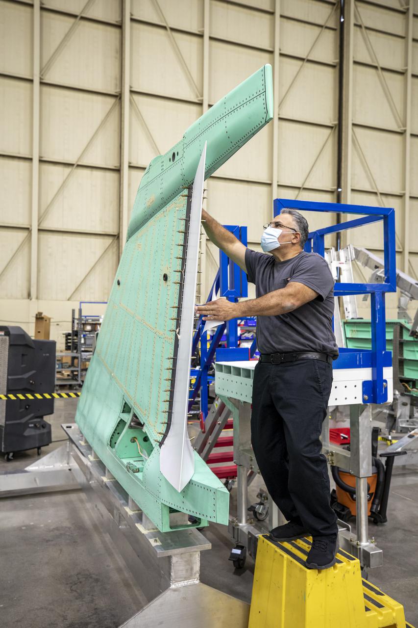
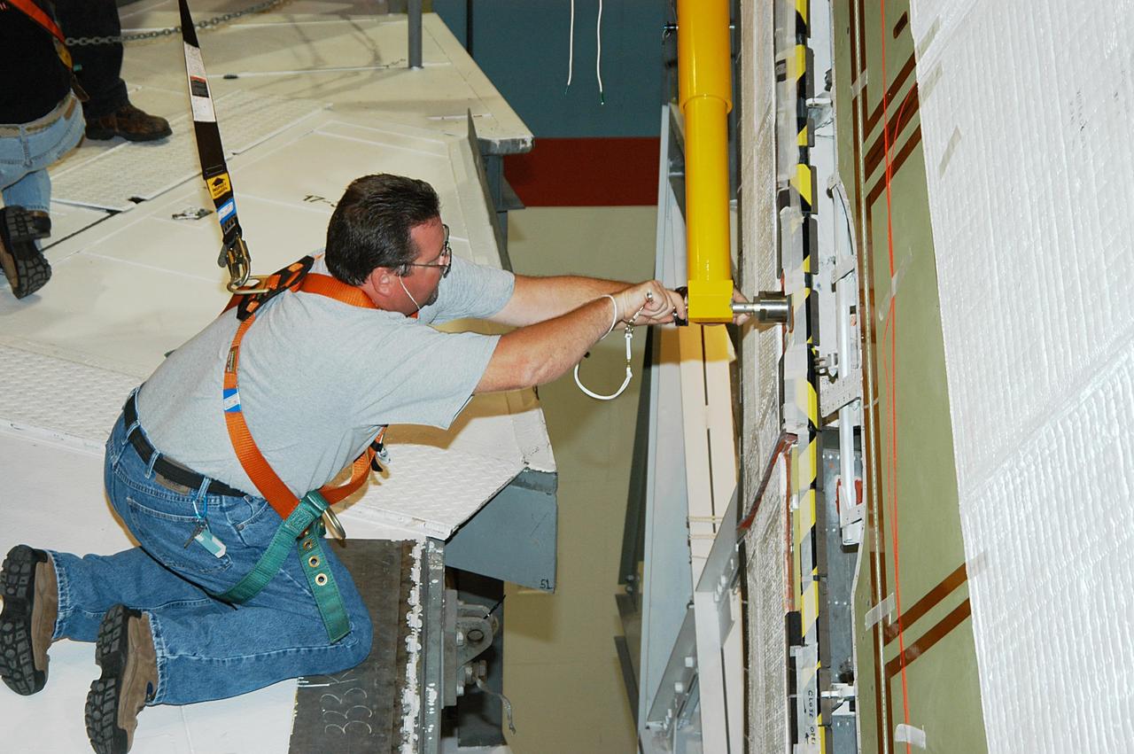
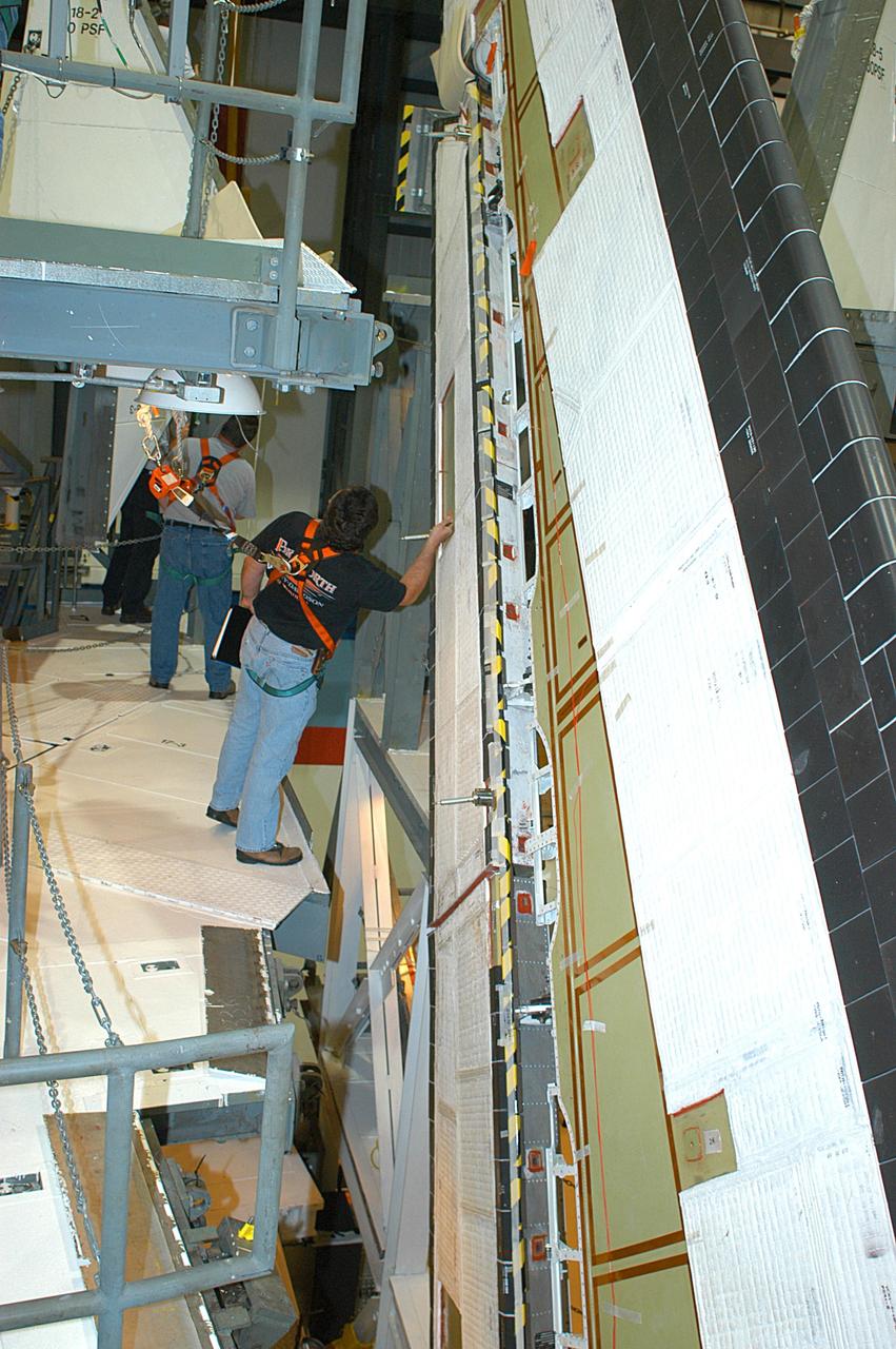
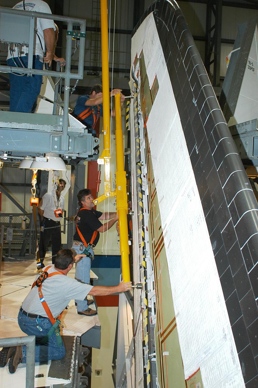
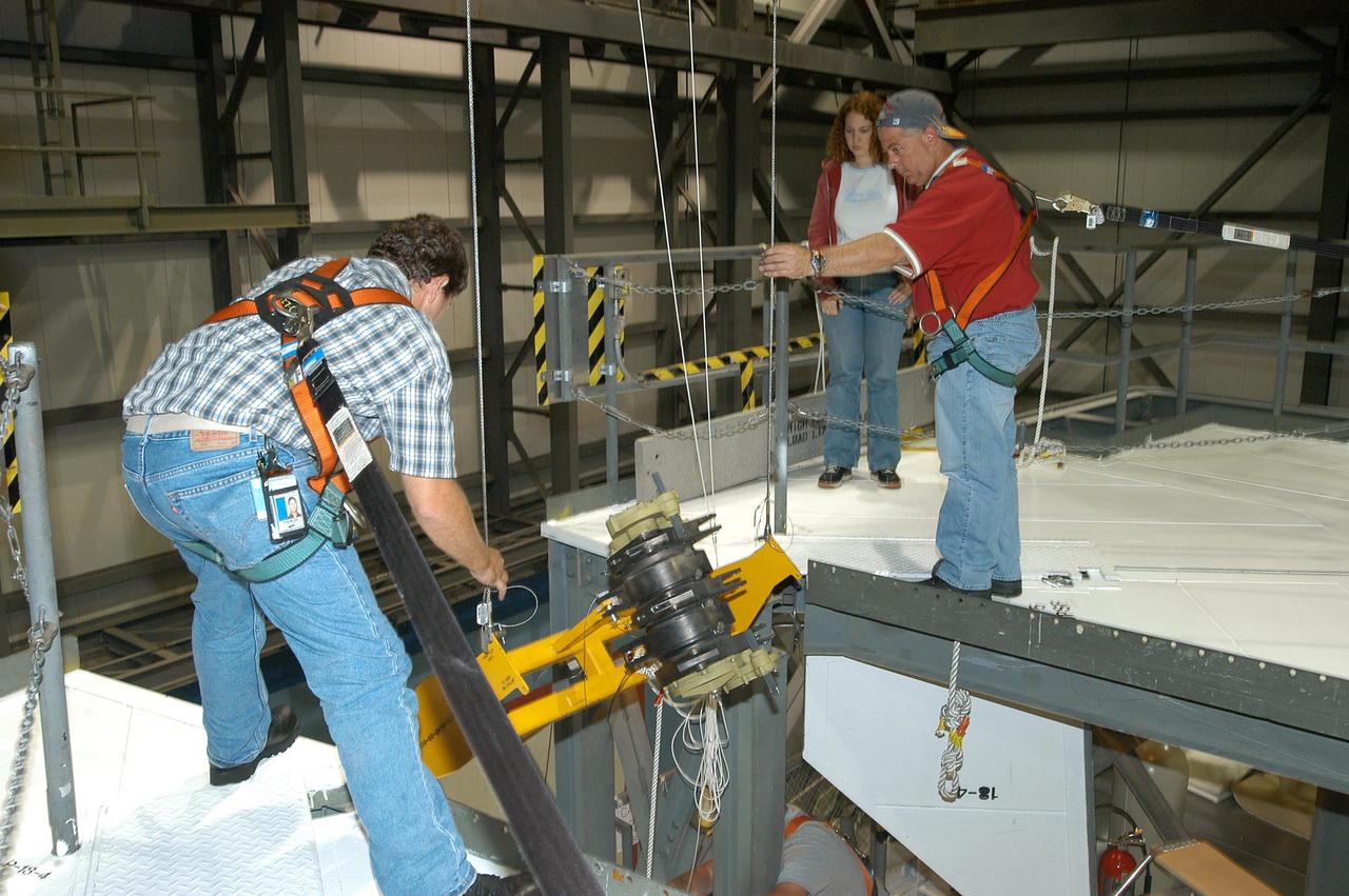
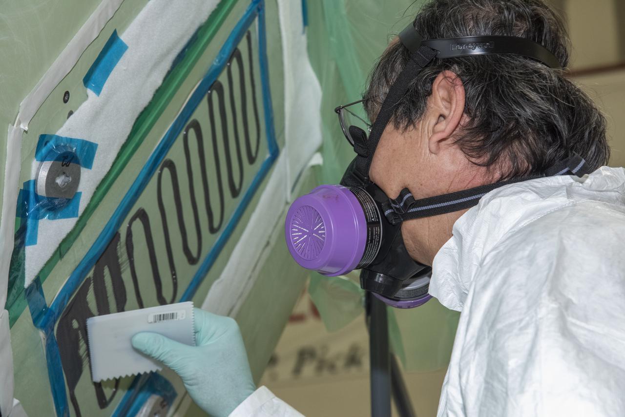
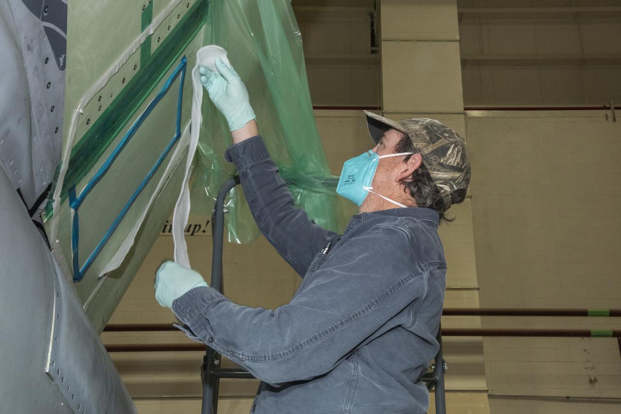
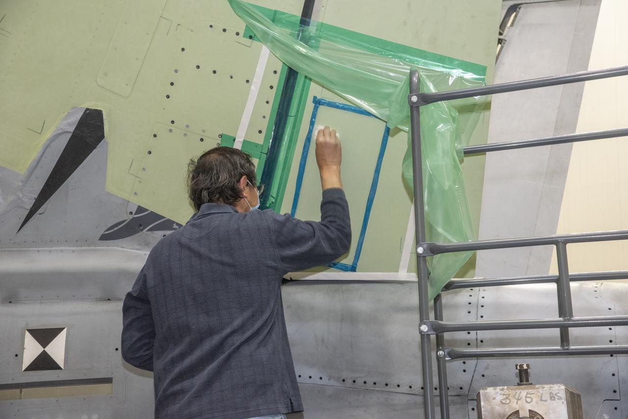
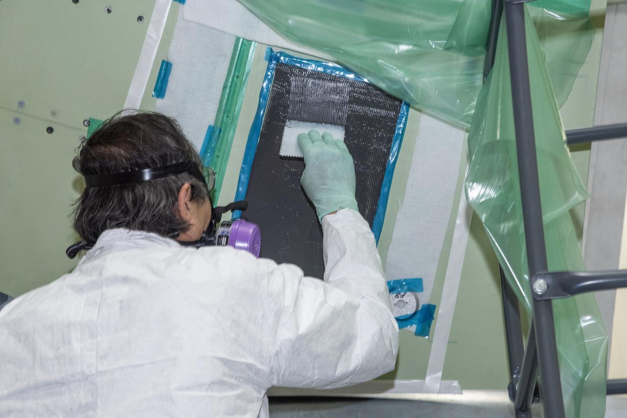
A technician is shown working on the X-59 vertical tail prior to installation. The aircraft, under construction at Lockheed Martin Skunk Works in Palmdale, California, will fly to demonstrate the ability to fly supersonic while reducing the loud sonic boom to a quiet sonic thump. Lockheed Martin Photography By Garry Tice 1011 Lockheed Way, Palmdale, Ca. 93599 Event: SEG 530 Vertical Tail - Rudder Installed Date: 5/12/2021
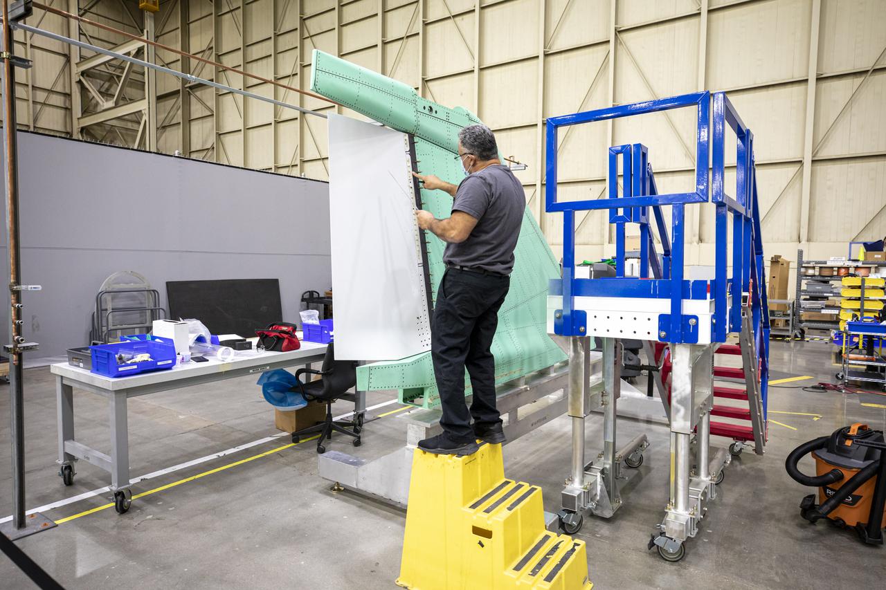
A technician is shown working on the X-59 Quiet SuperSonic Technology or QueSST aircraft’s vertical tail prior to installation. Lockheed Martin Photography By Garry Tice 1011 Lockheed Way, Palmdale, Ca. 93599 Event: SEG 530 Vertical Tail - Rudder Installed Date: 5/12/2021
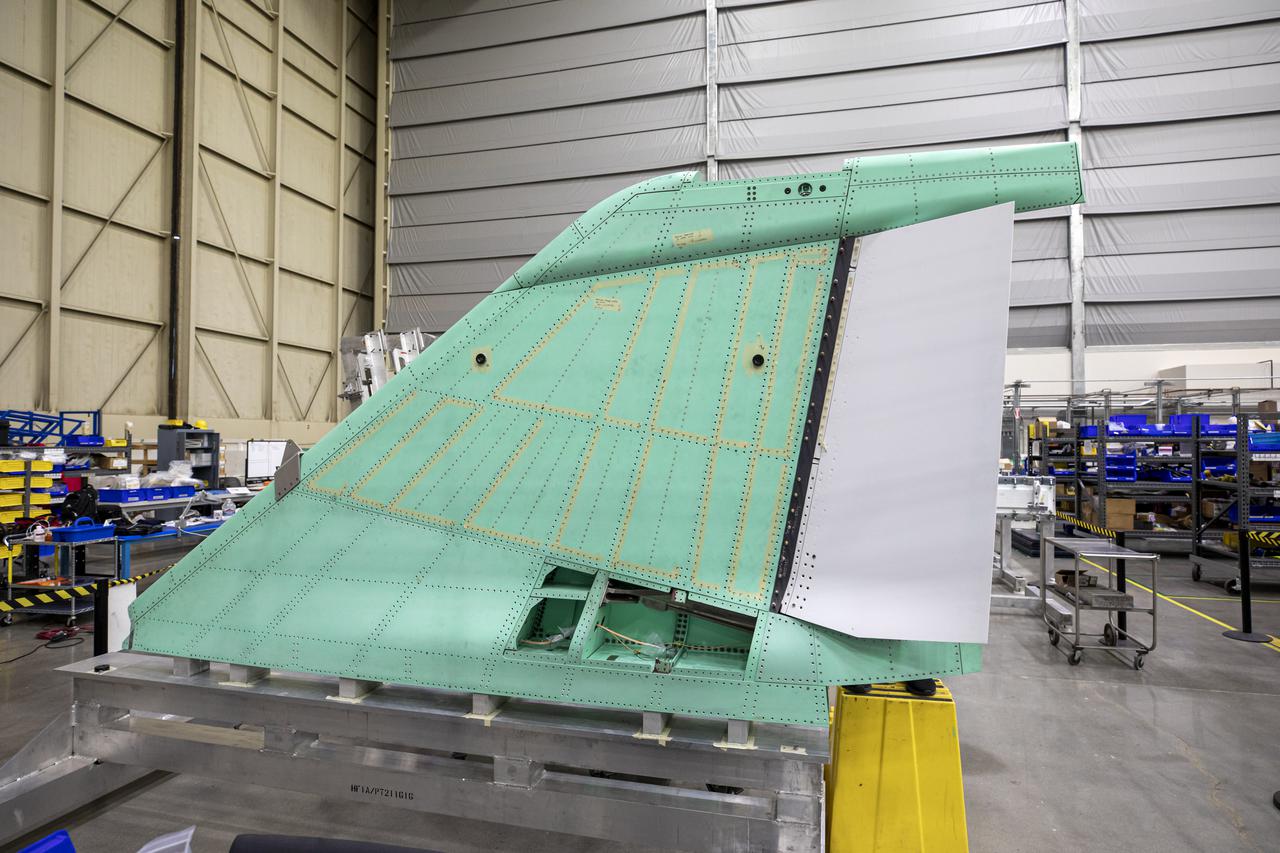
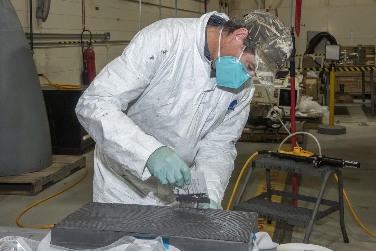
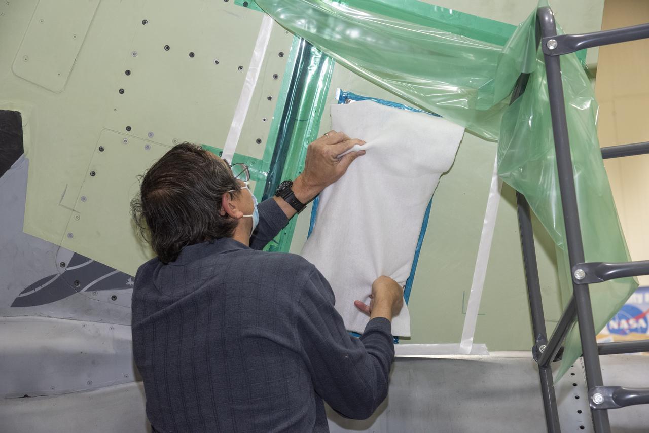
Pictured here is a close up view of the X-59 Quiet SuperSonic Technology or QueSST aircraft’s vertical tail prior to installation. Lockheed Martin Photography By Garry Tice 1011 Lockheed Way, Palmdale, Ca. 93599 Event: SEG 530 Vertical Tail - Rudder Installed Date: 5/12/2021
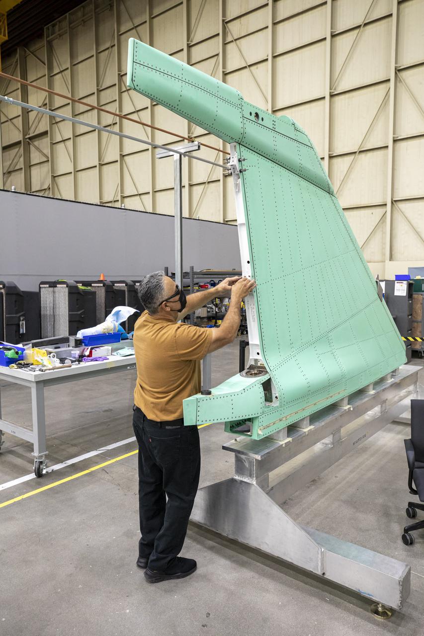
A technician is shown working on the X-59 vertical tail prior to installation at Lockheed Martin Skunk Works in Palmdale, California. The aircraft will fly to demonstrate the ability to fly supersonic while reducing the loud sonic boom to a quiet sonic thump. Lockheed Martin Photography By Garry Tice 1011 Lockheed Way, Palmdale, Ca. 93599 Event: SEG 530 Vertical Tail, Landing Gear Bay Doors Date: 4/28/2021
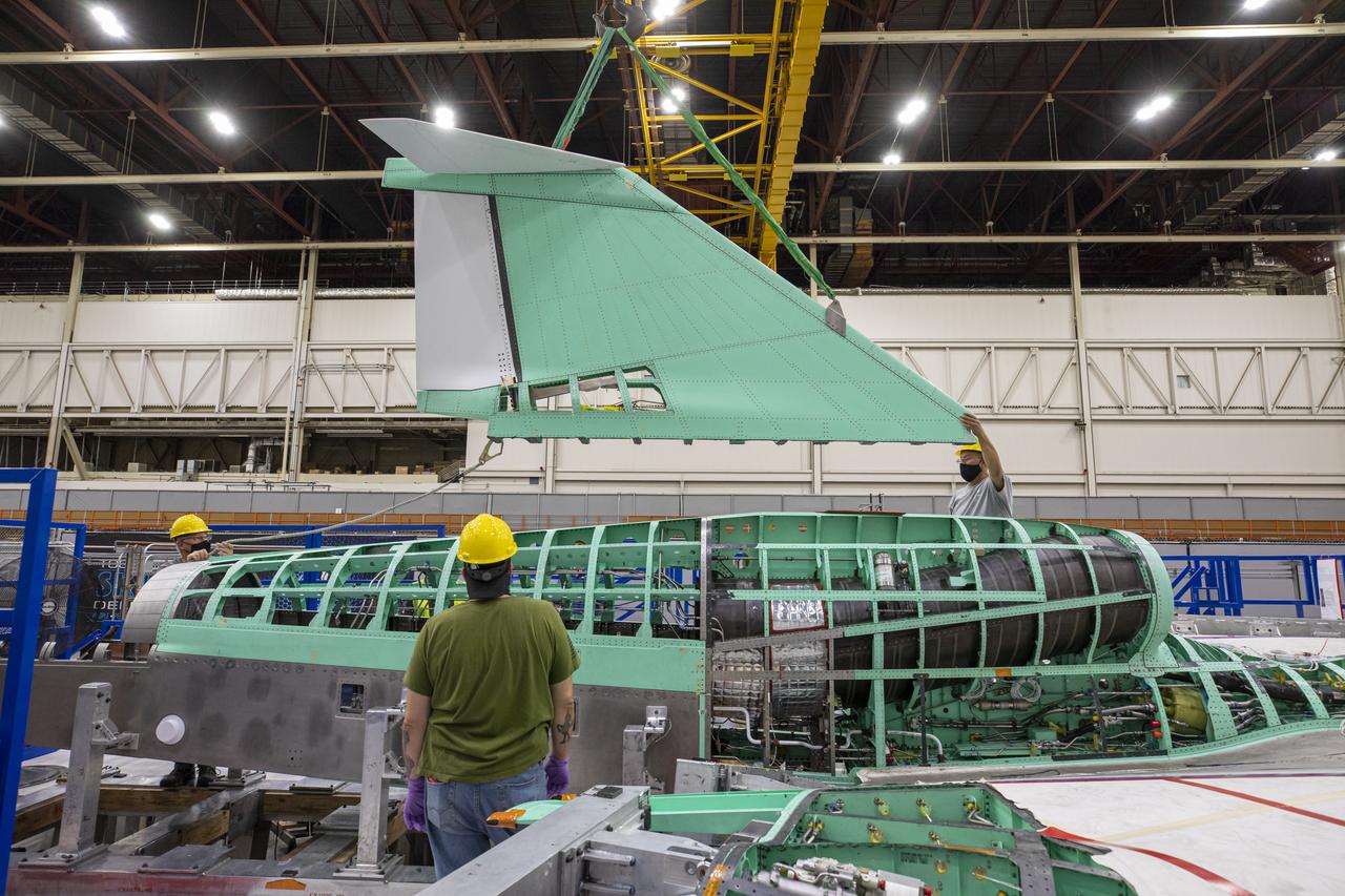
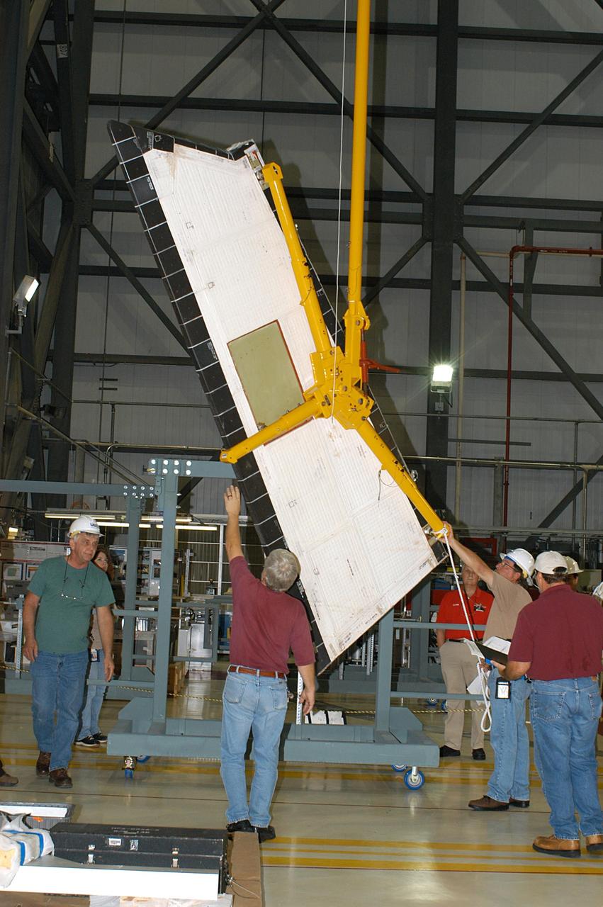
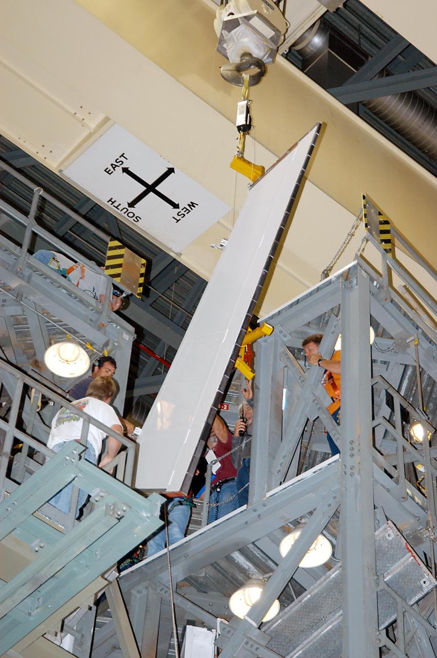
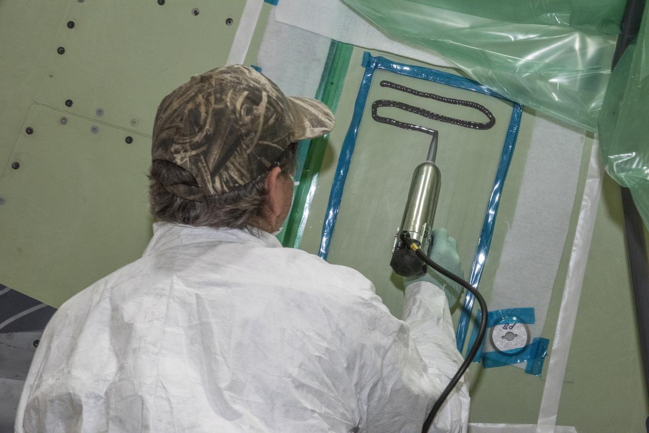
Event: SEG 570 Vertical Tail Assembly - Final Install Lockheed Martin technicians work on a fit check and installation of the vertical tail onto the X-59 aircraft. The plane is under construction at Lockheed Martin Skunk Works in Palmdale, California, will fly to demonstrate the ability to fly supersonic while reducing the loud sonic boom to a quiet sonic thump.
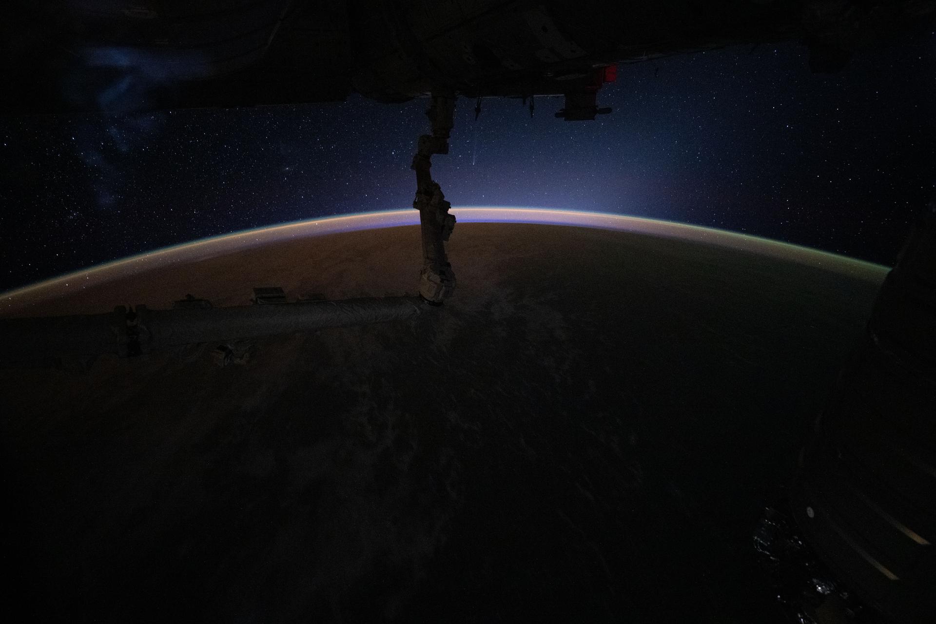
iss074e0480485 (April 17, 2026) --- This celestial image, taken moments before an orbital sunrise, reveals more than an airglow crowning Earth’s horizon—it also captures Comet C/2025 R3 (PANSTARRS) and its faint vertical tail (top center) at a distance of about 50 million miles from our planet. The International Space Station was orbiting 259 miles above the Pacific Ocean at approximately 3:50 a.m. local time when this photograph was taken. Credit: NASA/Chris Williams
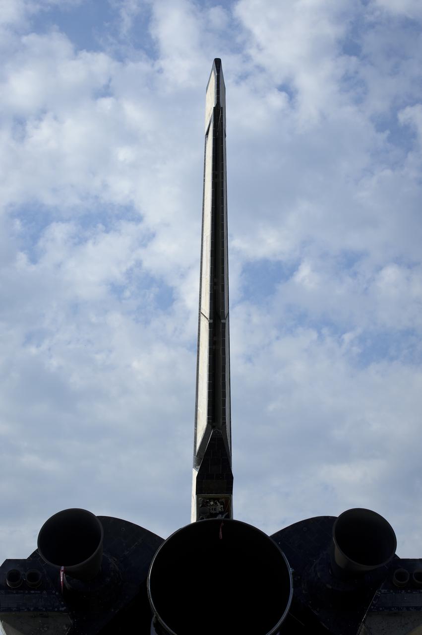
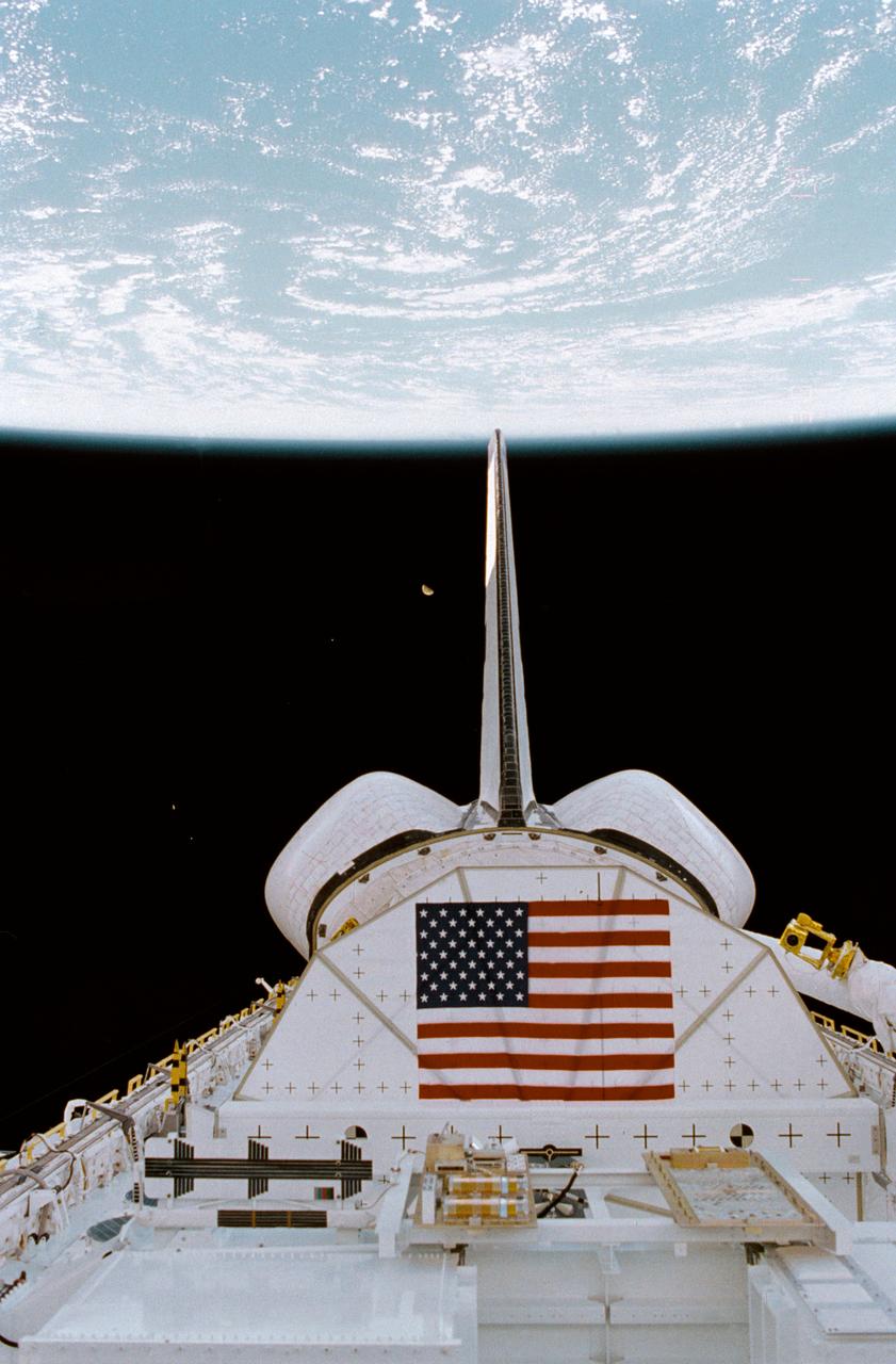
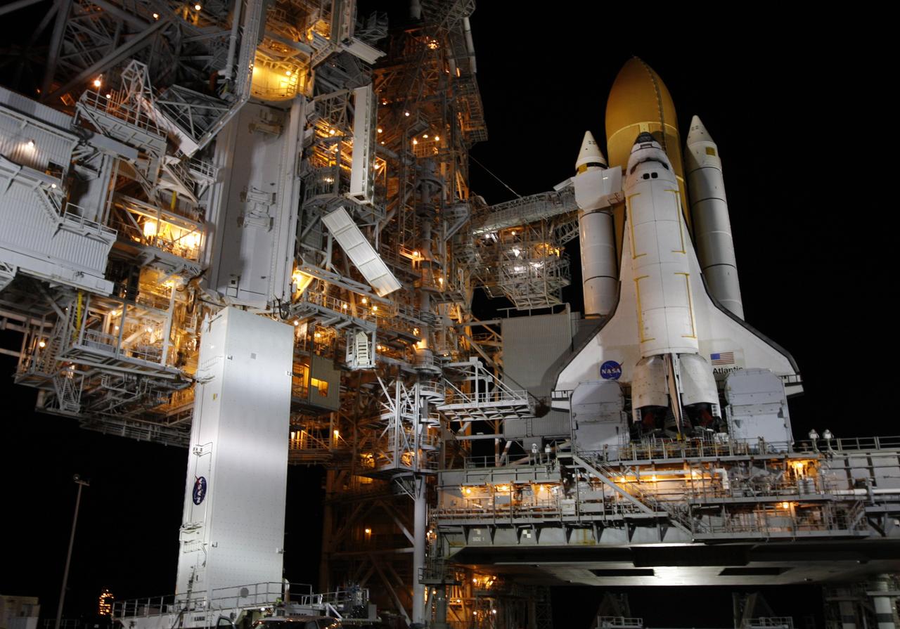
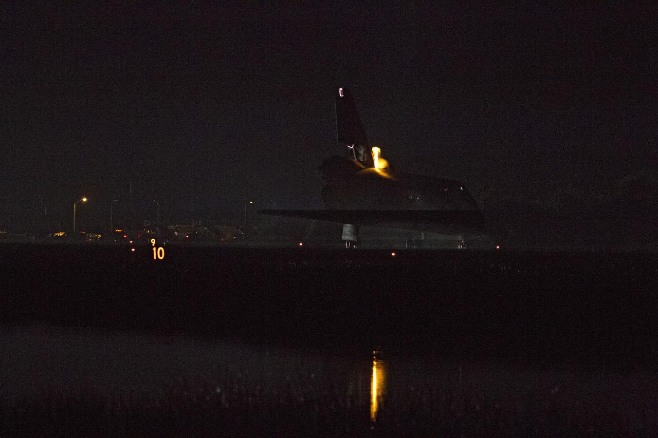
The vertical tail of the space shuttle Atlantis is seen at the Kennedy Space Center Shuttle Landing Facility (SLF) shortly after Atlantis (STS-135) landed early Thursday morning, July 21, 2011, in Cape Canaveral, Fla. Overall, Atlantis spent 307 days in space and traveled nearly 126 million miles during its 33 flights. Atlantis, the fourth orbiter built, launched on its first mission on Oct. 3, 1985. Photo Credit: (NASA/Bill Ingalls)
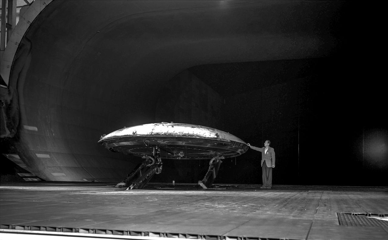
Rear view of the Avrocar without the tail, with ground board and variable height struts. The air force wanted to test the design of a flying saucer with vertical takeoff and landing capability. The design proved unstable without the tail.
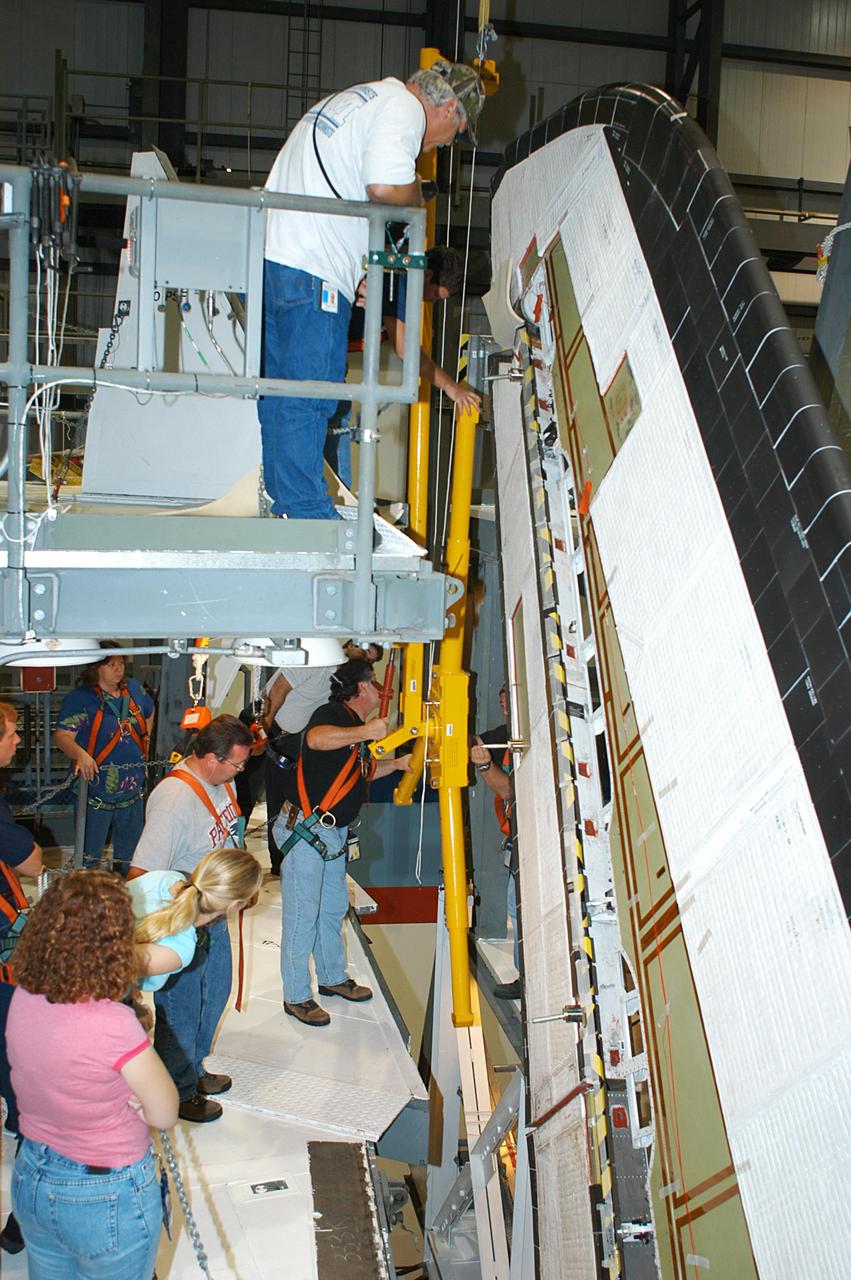
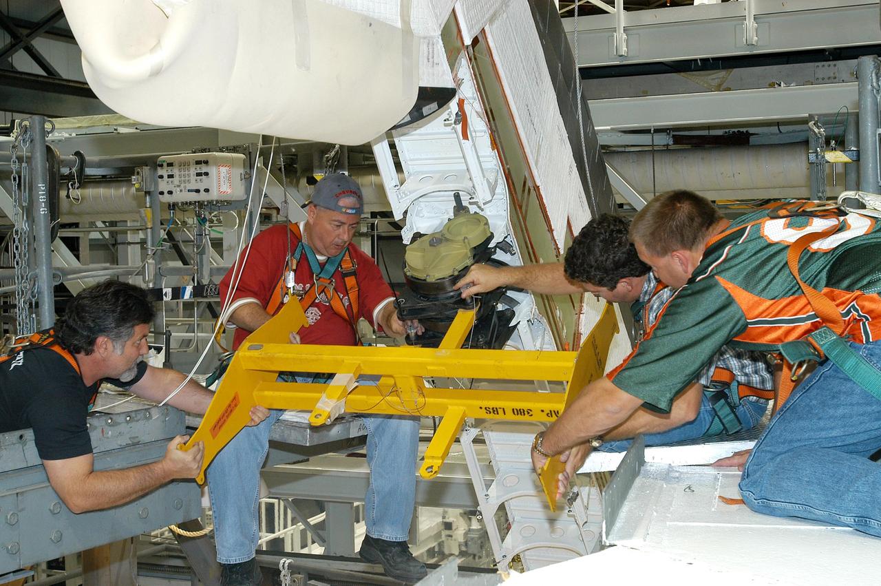
KENNEDY SPACE CENTER, FLA. -- In the Orbiter Processing Facility, a worker (below the upper framework) begins connecting a device to remove the Rudder Speed Brake panel on the vertical tail of orbiter Atlantis. The Rudder Speed Brake is being removed for inspection and maintenance prior to Return to Flight. The vertical tail consists of a structural fin surface made of aluminum, the Rudder Speed Brake surface, a tip and a lower trailing edge. The rudder splits into two halves to serve as a speed brake. The vertical tail and Rudder Speed Brake are covered with a reusable thermal protection system. The Rudder Speed Brake is used to guide and slow the Shuttle as it comes in for a landing.
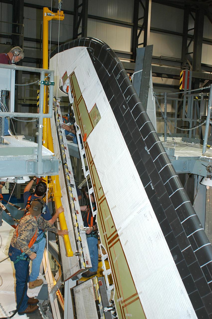
KENNEDY SPACE CENTER, FLA. -- In the Orbiter Processing Facility, workers remove the Rudder Speed Brake panel on the vertical tail of the orbiter Atlantis. The Rudder Speed Brake is being removed for inspection and maintenance prior to Return to Flight. The vertical tail consists of a structural fin surface made of aluminum, the Rudder Speed Brake surface, a tip and a lower trailing edge. The rudder splits into two halves to serve as a speed brake. The vertical tail and Rudder Speed Brake are covered with a reusable thermal protection system. The Rudder Speed Brake is used to guide and slow the Shuttle as it comes in for a landing.
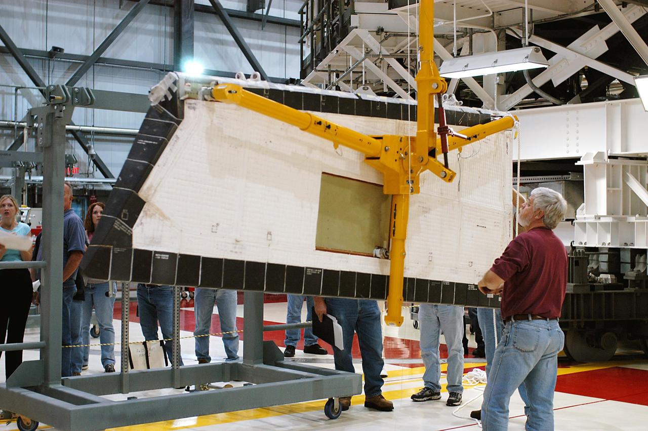
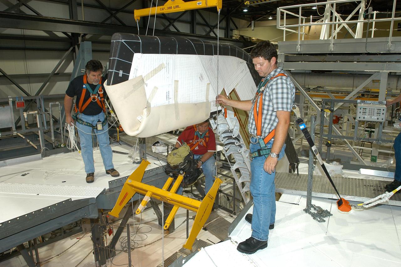
KENNEDY SPACE CENTER, FLA. -- In the Orbiter Processing Facility, workers lower Atlantis’ Rudder Speed Brake panel onto a stand after removing the panel from the vertical tail. The Rudder Speed Brake is being removed for inspection and maintenance prior to Return to Flight. The vertical tail consists of a structural fin surface made of aluminum, the Rudder Speed Brake surface, a tip and a lower trailing edge. The rudder splits into two halves to serve as a speed brake. The vertical tail and Rudder Speed Brake are covered with a reusable thermal protection system. The Rudder Speed Brake is used to guide and slow the Shuttle as it comes in for a landing.
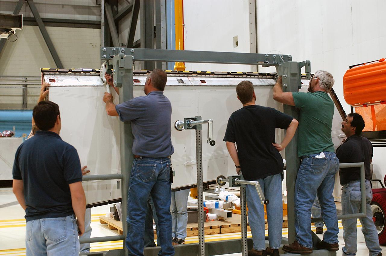
KENNEDY SPACE CENTER, FLA. -- In the Orbiter Processing Facility, workers attach Atlantis’ Rudder Speed Brake panel to a stand after removing the panel from the vertical tail. The Rudder Speed Brake is being removed for inspection and maintenance prior to Return to Flight. The vertical tail consists of a structural fin surface made of aluminum, the Rudder Speed Brake surface, a tip and a lower trailing edge. The rudder splits into two halves to serve as a speed brake. The vertical tail and Rudder Speed Brake are covered with a reusable thermal protection system. The Rudder Speed Brake is used to guide and slow the Shuttle as it comes in for a landing.
KENNEDY SPACE CENTER, FLA. -- In the Orbiter Processing Facility, a worker tightens a fitting on the device being used to remove the Rudder Speed Brake panel on the vertical tail of the orbiter Atlantis. The Rudder Speed Brake is being removed for inspection and maintenance prior to Return to Flight. The vertical tail consists of a structural fin surface made of aluminum, the Rudder Speed Brake surface, a tip and a lower trailing edge. The rudder splits into two halves to serve as a speed brake. The vertical tail and Rudder Speed Brake are covered with a reusable thermal protection system. The Rudder Speed Brake is used to guide and slow the Shuttle as it comes in for a landing.

KENNEDY SPACE CENTER, FLA. -- In the Orbiter Processing Facility, workers attach Atlantis’ Rudder Speed Brake panel to a stand after removing the panel from the vertical tail. The Rudder Speed Brake is being removed for inspection and maintenance prior to Return to Flight. The vertical tail consists of a structural fin surface made of aluminum, the Rudder Speed Brake surface, a tip and a lower trailing edge. The rudder splits into two halves to serve as a speed brake. The vertical tail and Rudder Speed Brake are covered with a reusable thermal protection system. The Rudder Speed Brake is used to guide and slow the Shuttle as it comes in for a landing.
KENNEDY SPACE CENTER, FLA. -- In the Orbiter Processing Facility, workers lower Atlantis’ Rudder Speed Brake panel toward the floor after removing the panel from the vertical tail. The Rudder Speed Brake is being removed for inspection and maintenance prior to Return to Flight. The vertical tail consists of a structural fin surface made of aluminum, the Rudder Speed Brake surface, a tip and a lower trailing edge. The rudder splits into two halves to serve as a speed brake. The vertical tail and Rudder Speed Brake are covered with a reusable thermal protection system. The Rudder Speed Brake is used to guide and slow the Shuttle as it comes in for a landing.
KENNEDY SPACE CENTER, FLA. -- In the Orbiter Processing Facility, a technician looks at the Rudder Speed Brake panel on the vertical tail of orbiter Atlantis. The Rudder Speed Brake is being removed for inspection and maintenance prior to Return to Flight. The vertical tail consists of a structural fin surface made of aluminum, the Rudder Speed Brake surface, a tip and a lower trailing edge. The rudder splits into two halves to serve as a speed brake. The vertical tail and Rudder Speed Brake are covered with a reusable thermal protection system. The Rudder Speed Brake is used to guide and slow the Shuttle as it comes in for a landing.
KENNEDY SPACE CENTER, FLA. -- In the Orbiter Processing Facility, workers connect a device onto the vertical tail of the orbiter Atlantis to remove the Rudder Speed Brake panel. The Rudder Speed Brake is being removed for inspection and maintenance prior to Return to Flight. The vertical tail consists of a structural fin surface made of aluminum, the Rudder Speed Brake surface, a tip and a lower trailing edge. The rudder splits into two halves to serve as a speed brake. The vertical tail and Rudder Speed Brake are covered with a reusable thermal protection system. The Rudder Speed Brake is used to guide and slow the Shuttle as it comes in for a landing.
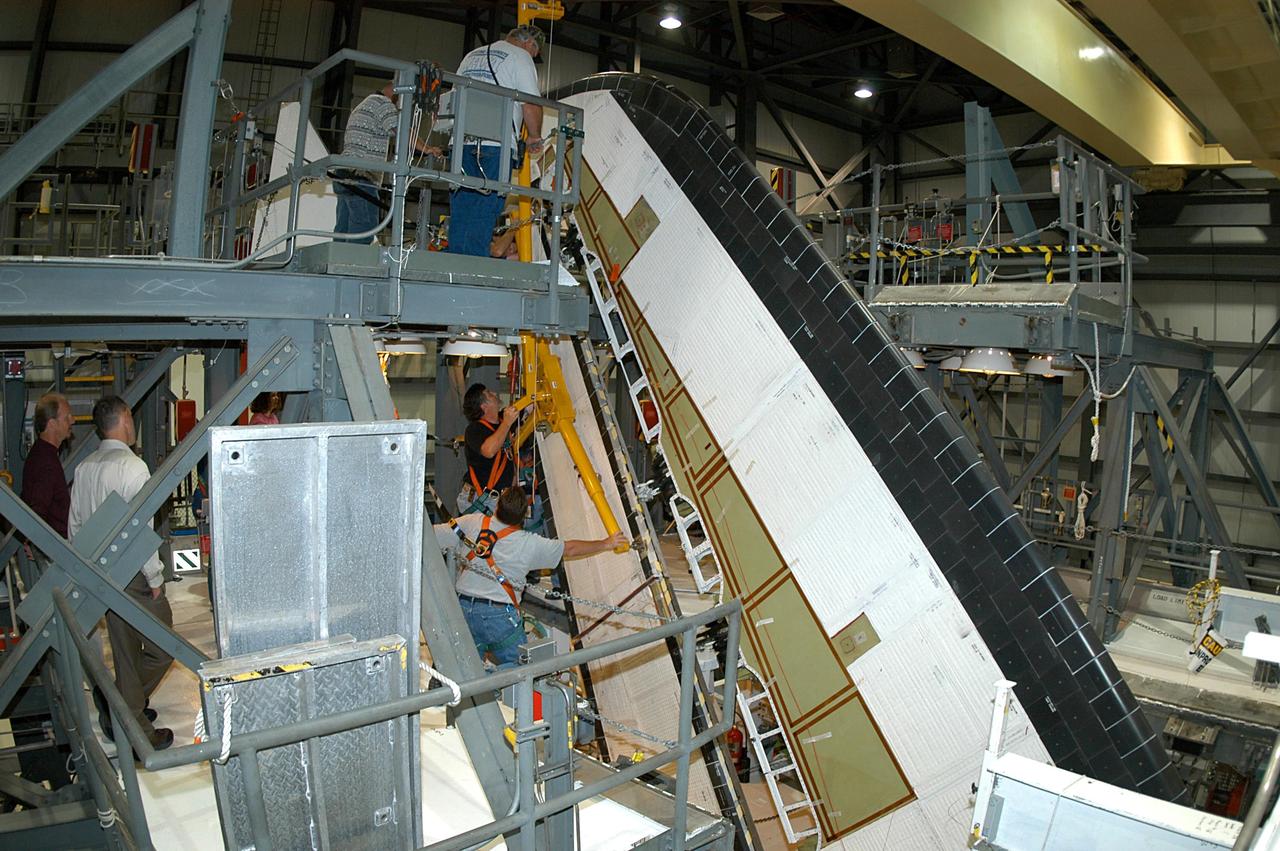
KENNEDY SPACE CENTER, FLA. -- In the Orbiter Processing Facility, workers begin removing the Rudder Speed Brake panel on the vertical tail of the orbiter Atlantis. The Rudder Speed Brake is being removed for inspection and maintenance prior to Return to Flight. The vertical tail consists of a structural fin surface made of aluminum, the Rudder Speed Brake surface, a tip and a lower trailing edge. The rudder splits into two halves to serve as a speed brake. The vertical tail and Rudder Speed Brake are covered with a reusable thermal protection system. The Rudder Speed Brake is used to guide and slow the Shuttle as it comes in for a landing.
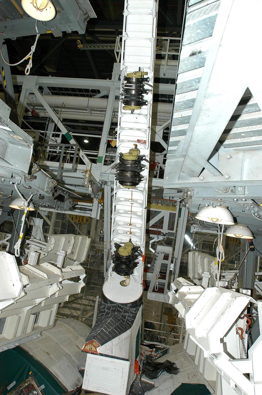
KENNEDY SPACE CENTER, FLA. -- A Rudder Speed Brake Actuator is being removed from the orbiter Atlantis for shipment to the vendor for inspection. An actuator is a motor that moves the tail rudder back and forth to help steer it during landing and brake its speed. The vertical tail consists of a structural fin surface made of aluminum, the Rudder Speed Brake surface, a tip and a lower trailing edge. The rudder splits into two halves to serve as a speed brake. The vertical tail and Rudder Speed Brake are covered with a reusable thermal protection system. Atlantis is undergoing maintenance and inspection in the Orbiter Processing Facility for a future mission.
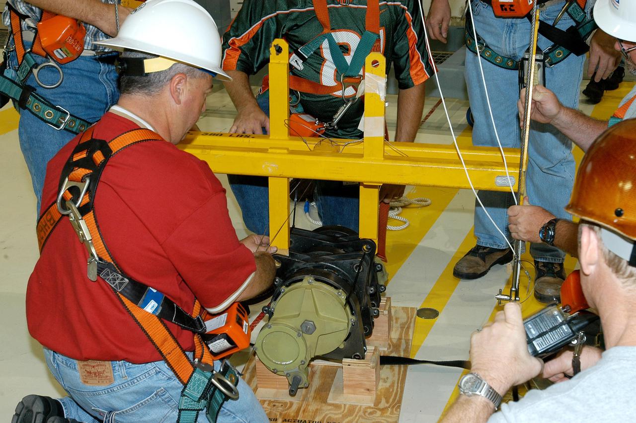
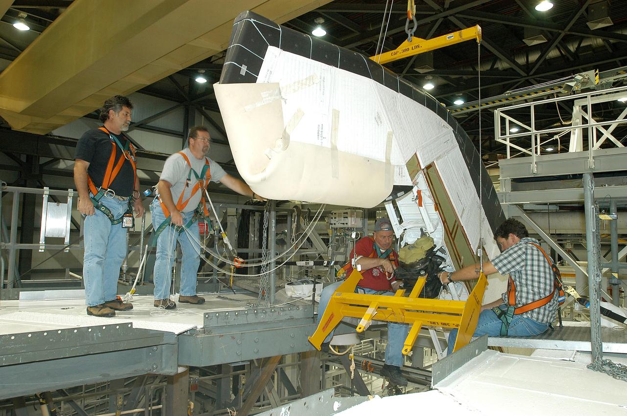
KENNEDY SPACE CENTER, FLA. -- Workers ensure the safe removal of a Rudder Speed Brake Actuator from the orbiter Atlantis. This and three other actuators are being shipped to the vendor for inspection. An actuator is a motor that moves the tail rudder back and forth to help steer it during landing and brake its speed. The vertical tail consists of a structural fin surface made of aluminum, the Rudder Speed Brake surface, a tip and a lower trailing edge. The rudder splits into two halves to serve as a speed brake. The vertical tail and Rudder Speed Brake are covered with a reusable thermal protection system. Atlantis is undergoing maintenance and inspection in the Orbiter Processing Facility for a future mission.
KENNEDY SPACE CENTER, FLA. -- A Rudder Speed Brake Actuator from the orbiter Atlantis is set on a stand on the floor of the Orbiter Processing Facility. This and three other actuators are being shipped to the vendor for inspection. An actuator is a motor that moves the tail rudder back and forth to help steer it during landing and brake its speed. The vertical tail consists of a structural fin surface made of aluminum, the Rudder Speed Brake surface, a tip and a lower trailing edge. The rudder splits into two halves to serve as a speed brake. The vertical tail and Rudder Speed Brake are covered with a reusable thermal protection system. Atlantis is undergoing maintenance and inspection for a future mission.
KENNEDY SPACE CENTER, FLA. -- Workers attach a crane to one of the Rudder Speed Brake Actuators that are being removed from the orbiter Atlantis for shipment to the vendor for inspection. An actuator is a motor that moves the tail rudder back and forth to help steer it during landing and brake its speed. The vertical tail consists of a structural fin surface made of aluminum, the Rudder Speed Brake surface, a tip and a lower trailing edge. The rudder splits into two halves to serve as a speed brake. The vertical tail and Rudder Speed Brake are covered with a reusable thermal protection system. Atlantis is undergoing maintenance and inspection in the Orbiter Processing Facility for a future mission.
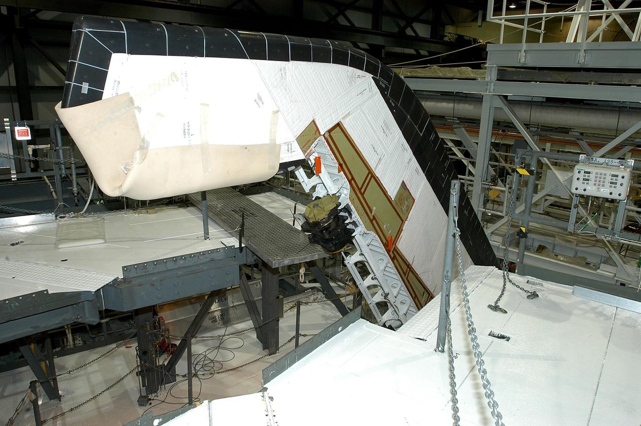
KENNEDY SPACE CENTER, FLA. -- A Rudder Speed Brake Actuator is being removed from the orbiter Atlantis for shipment to the vendor for inspection. An actuator is a motor that moves the tail rudder back and forth to help steer it during landing and brake its speed. The vertical tail consists of a structural fin surface made of aluminum, the Rudder Speed Brake surface, a tip and a lower trailing edge. The rudder splits into two halves to serve as a speed brake. The vertical tail and Rudder Speed Brake are covered with a reusable thermal protection system. Atlantis is undergoing maintenance and inspection in the Orbiter Processing Facility for a future mission.
KENNEDY SPACE CENTER, FLA. -- Workers attach a crane to one of the Rudder Speed Brake Actuators that are being removed from the orbiter Atlantis for shipment to the vendor for inspection. An actuator is a motor that moves the tail rudder back and forth to help steer it during landing and brake its speed. The vertical tail consists of a structural fin surface made of aluminum, the Rudder Speed Brake surface, a tip and a lower trailing edge. The rudder splits into two halves to serve as a speed brake. The vertical tail and Rudder Speed Brake are covered with a reusable thermal protection system. Atlantis is undergoing maintenance and inspection in the Orbiter Processing Facility for a future mission.
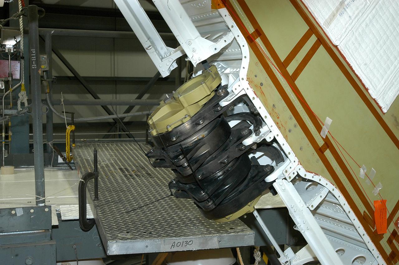
KENNEDY SPACE CENTER, FLA. -- This is a closeup of one of the Rudder Speed Brake Actuators that are being removed from the orbiter Atlantis for shipment to the vendor for inspection. An actuator is a motor that moves the tail rudder back and forth to help steer it during landing and brake its speed. The vertical tail consists of a structural fin surface made of aluminum, the Rudder Speed Brake surface, a tip and a lower trailing edge. The rudder splits into two halves to serve as a speed brake. The vertical tail and Rudder Speed Brake are covered with a reusable thermal protection system. Atlantis is undergoing maintenance and inspection in the Orbiter Processing Facility for a future mission.
KENNEDY SPACE CENTER, FLA. -- Workers ensure the safe removal of a Rudder Speed Brake Actuator from the orbiter Atlantis. This and three other actuators are being shipped to the vendor for inspection. An actuator is a motor that moves the tail rudder back and forth to help steer it during landing and brake its speed. The vertical tail consists of a structural fin surface made of aluminum, the Rudder Speed Brake surface, a tip and a lower trailing edge. The rudder splits into two halves to serve as a speed brake. The vertical tail and Rudder Speed Brake are covered with a reusable thermal protection system. Atlantis is undergoing maintenance and inspection in the Orbiter Processing Facility for a future mission.
KENNEDY SPACE CENTER, FLA. -- In the Orbiter Processing Facility, the Rudder Speed Brake panel from orbiter Atlantis is lifted clear after being removed. The Rudder Speed Brake is being removed for inspection and maintenance prior to Return to Flight. The vertical tail consists of a structural fin surface made of aluminum, the Rudder Speed Brake surface, a tip and a lower trailing edge. The rudder splits into two halves to serve as a speed brake. The vertical tail and Rudder Speed Brake are covered with a reusable thermal protection system. The Rudder Speed Brake is used to guide and slow the Shuttle as it comes in for a landing.
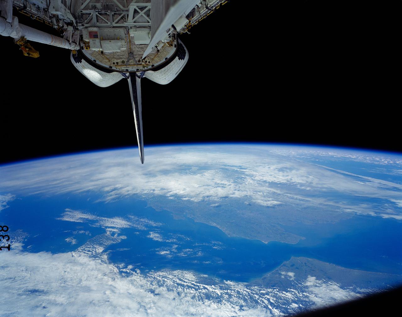
41G-121-138 (5-13 Oct 1984) --- A view of the Earth's horizon featuring France and England. The Strait of Dover and the English channel are visible behind the tail (vertical stabilizer) of Challenger. The remote manipulator system (RMS arm rests in its "stow" position at upper left corner.
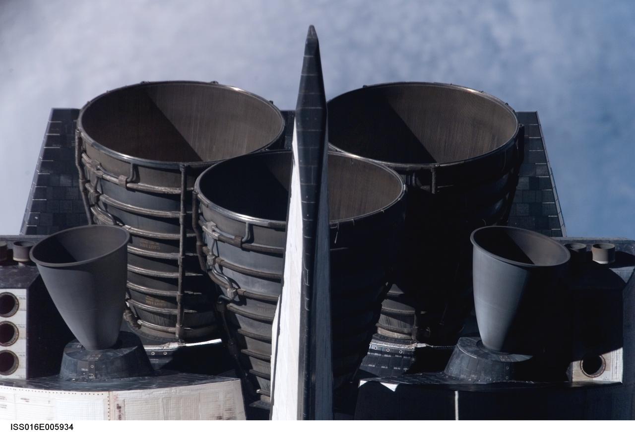
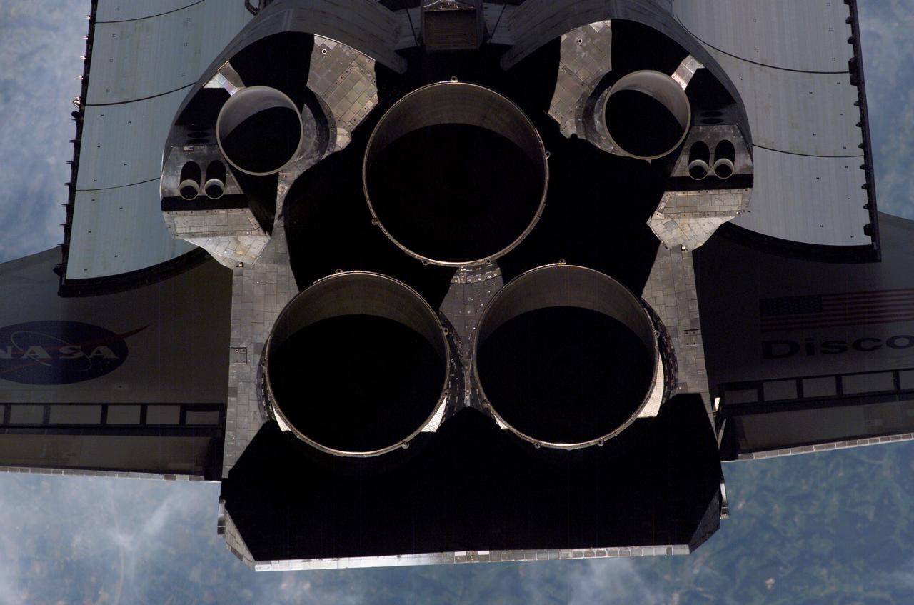
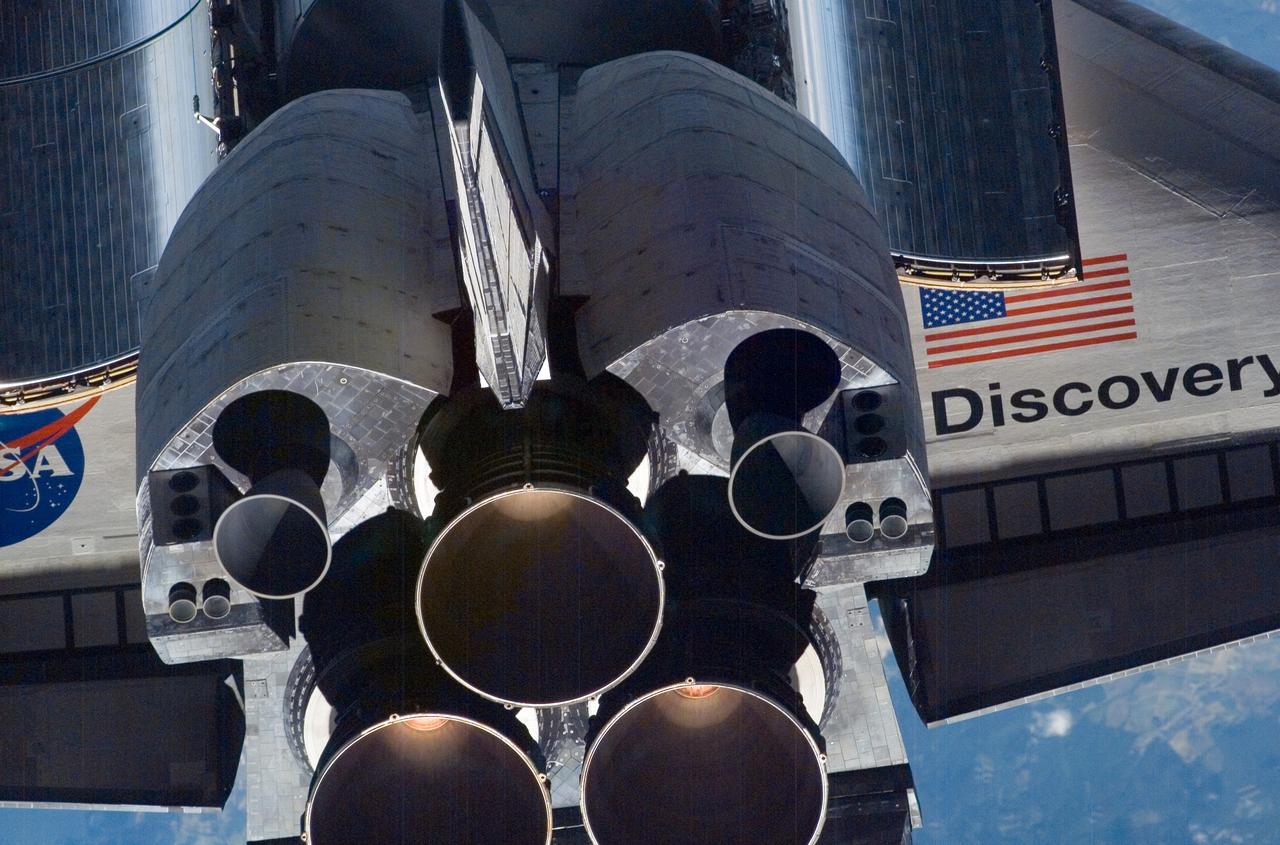
ISS016-E-005934 (25 Oct. 2007) --- The Space Shuttle Discovery's tail section is featured in this image photographed by an Expedition 16 crewmember during a backflip maneuver performed by the approaching visitors (STS-120) to the International Space Station. Visible are the shuttle's main engines and vertical stabilizer.
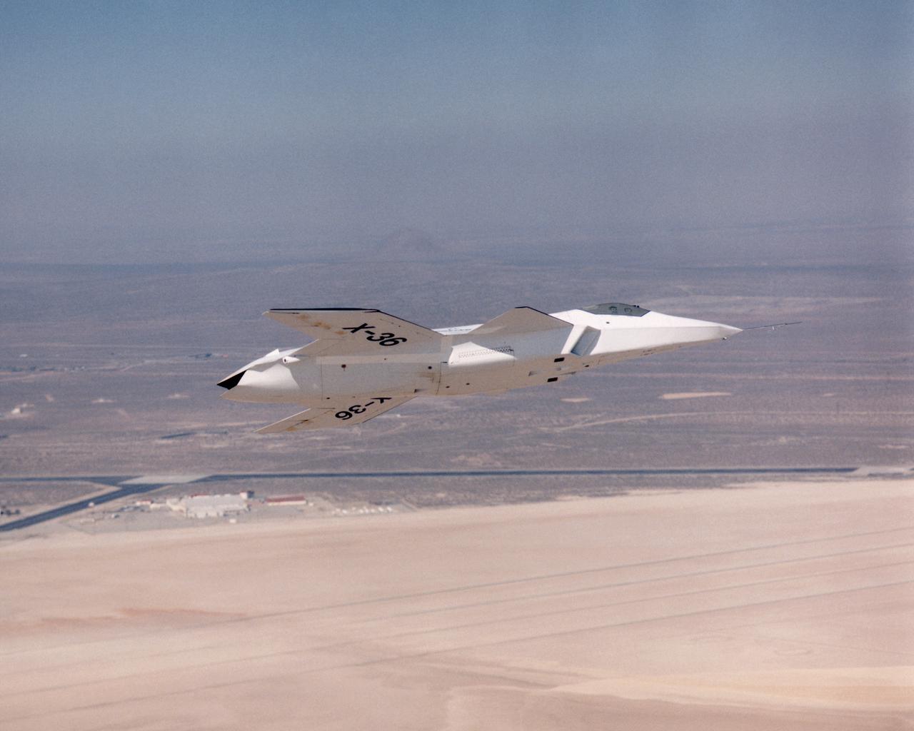
The lack of a vertical tail on the X-36 technology demonstrator is evident as the remotely piloted aircraft flies a low-altitude research flight above Rogers Dry Lake at Edwards Air Force Base in the California desert on October 30, 1997.
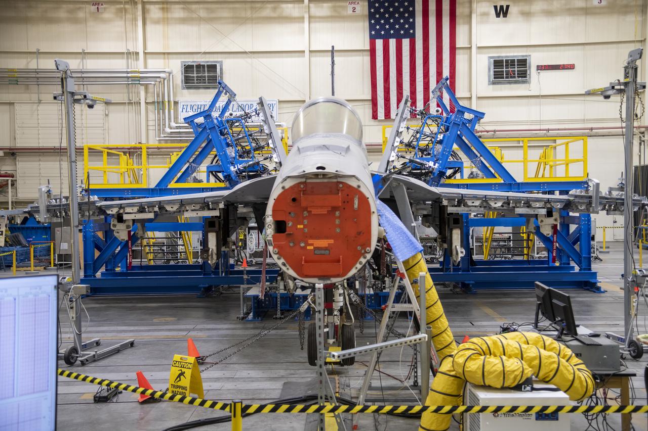
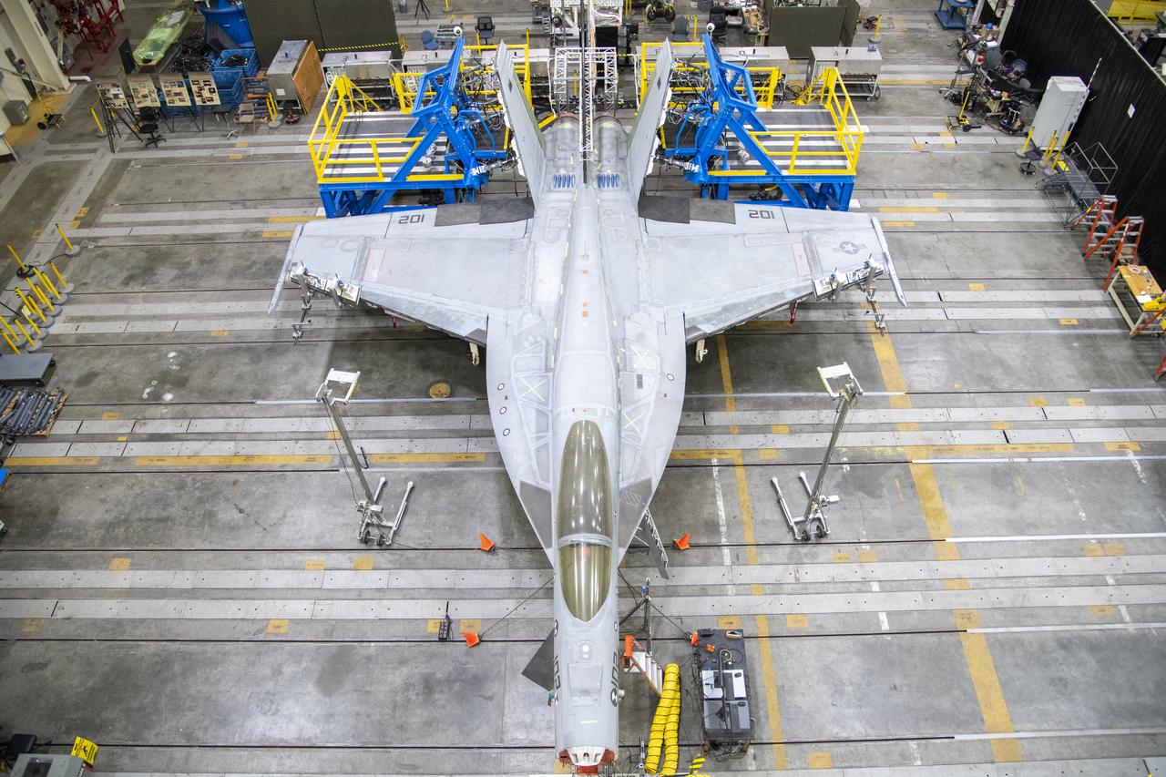
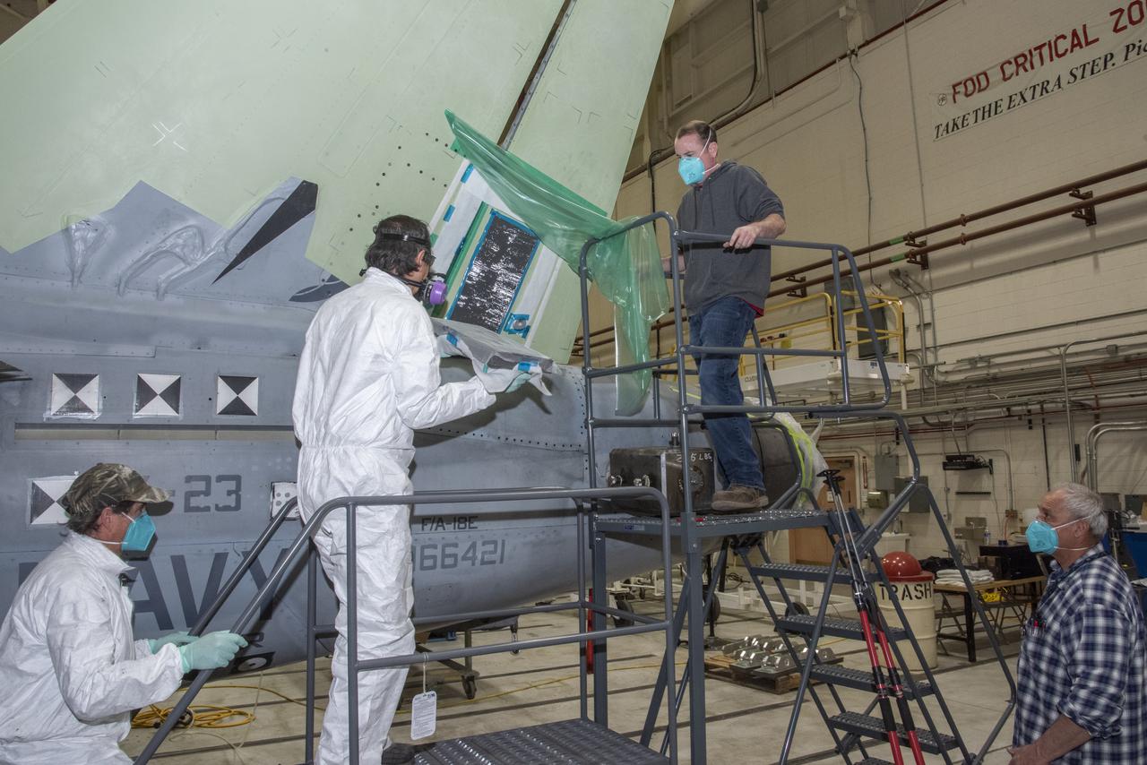
This is a front view of the vertical tail loads testing on a Navy F/A-18E that concluded in May, wrapping up the third phase of research at NASA’s Armstrong Flight Research Center in Edwards, California. The first two phases included loads calibration testing focused on the aircraft’s horizontal tails and wings. The aircraft is from the Naval Air Systems Command (NAVAIR) in Patuxent River, Maryland. NAVAIR retired its previous loads test aircraft and NASA Armstrong staff are assisting to prepare the new aircraft for its role to help safely manage flight maneuvers and determine how the F/A-18E fleet will perform if proposed upgrades are incorporated.
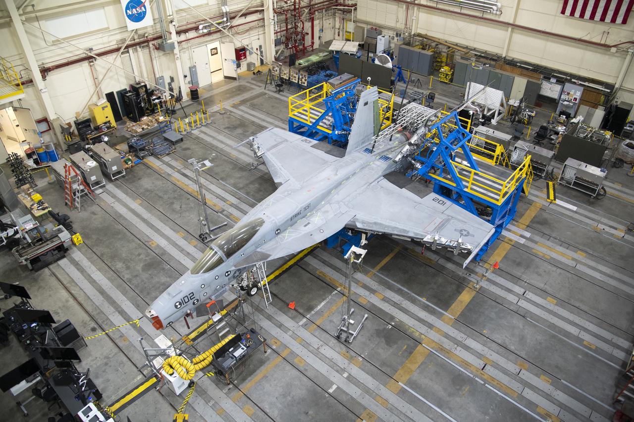
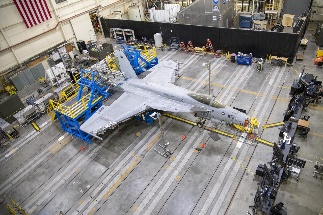
This view from above shows the vertical tail loads testing on a Navy F/A-18E that concluded in May, wrapping up the third phase of research at NASA’s Armstrong Flight Research Center in Edwards, California. The first two phases included loads calibration testing focused on the aircraft’s horizontal tails and wings. The aircraft is from the Naval Air Systems Command (NAVAIR) in Patuxent River, Maryland. NAVAIR retired its previous loads test aircraft and NASA Armstrong staff are assisting to prepare the new aircraft for its role to help safely manage flight maneuvers and determine how the F/A-18E fleet will perform if proposed upgrades are incorporated.
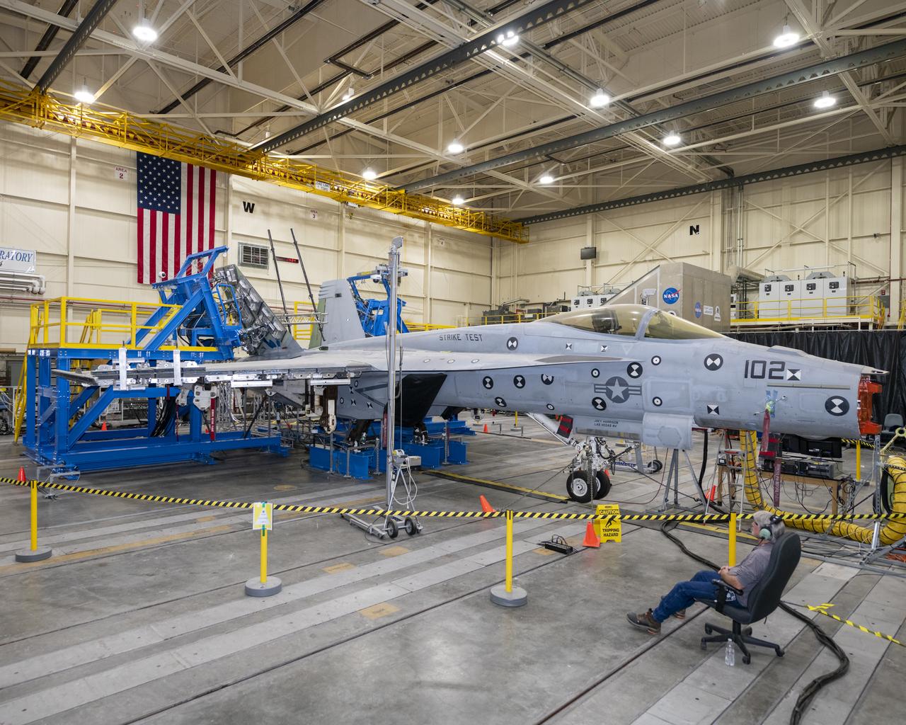
Here is another view of the vertical tail loads testing on a Navy F/A-18E that concluded in May, wrapping up the third phase of research at NASA’s Armstrong Flight Research Center in Edwards, California. The first two phases included loads calibration testing focused on the aircraft’s horizontal tails and wings. The aircraft is from the Naval Air Systems Command (NAVAIR) in Patuxent River, Maryland. NAVAIR retired its previous loads test aircraft and NASA Armstrong staff are assisting to prepare the new aircraft for its role to help safely manage flight maneuvers and determine how the F/A-18E fleet will perform if proposed upgrades are incorporated.
This view from above shows the vertical tail loads testing on a Navy F/A-18E that concluded in May, wrapping up the third phase of research at NASA’s Armstrong Flight Research Center in Edwards, California. The first two phases included loads calibration testing focused on the aircraft’s horizontal tails and wings. The aircraft is from the Naval Air Systems Command (NAVAIR) in Patuxent River, Maryland. NAVAIR retired its previous loads test aircraft and NASA Armstrong staff are assisting to prepare the new aircraft for its role to help safely manage flight maneuvers and determine how the F/A-18E fleet will perform if proposed upgrades are incorporated.
This view from above shows the vertical tail loads testing on a Navy F/A-18E that concluded in May, wrapping up the third phase of research at NASA’s Armstrong Flight Research Center in Edwards, California. The first two phases included loads calibration testing focused on the aircraft’s horizontal tails and wings. The aircraft is from the Naval Air Systems Command (NAVAIR) in Patuxent River, Maryland. NAVAIR retired its previous loads test aircraft and NASA Armstrong staff are assisting to prepare the new aircraft for its role to help safely manage flight maneuvers and determine how the F/A-18E fleet will perform if proposed upgrades are incorporated.
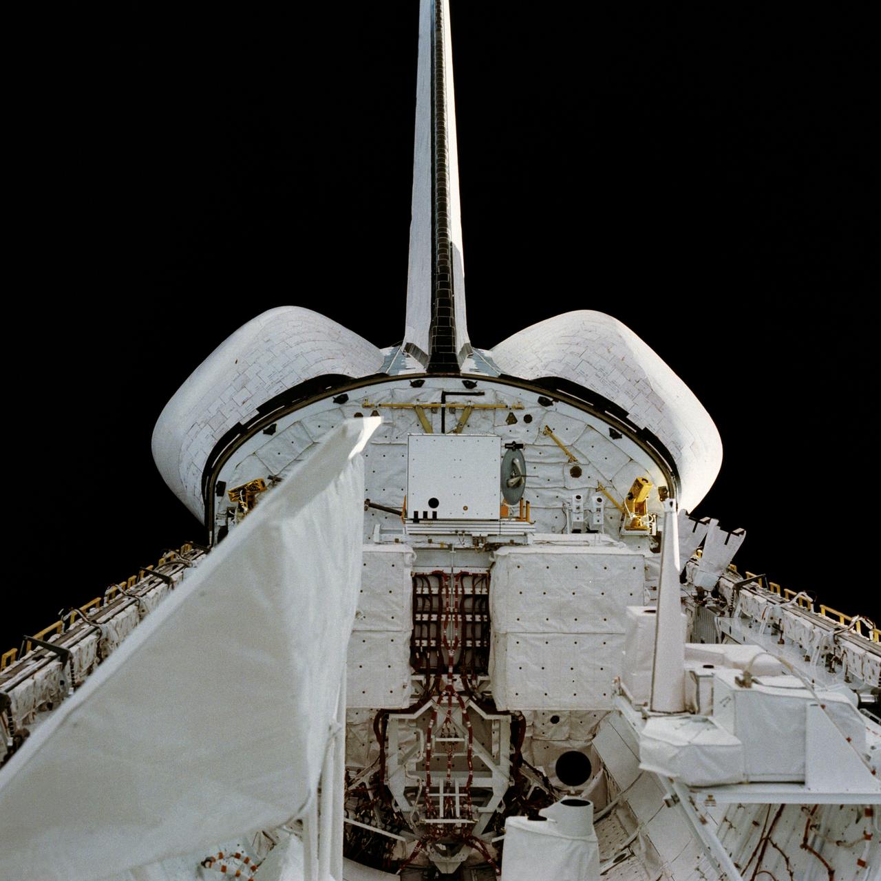
STS008-02-0041 (30 Aug-5 Sept 1983) --- An astronaut's eye view of two thirds of the cargo bay, the white and blue horizon scene of the Earth, and a gibbous moon was recorded on 35mm film from the aft flight deck of the Earth-orbiting Space Shuttle Challenger. The payload flight test article (PFTA) appears to be awaiting its heavy workout schedule in the middle of the bay.
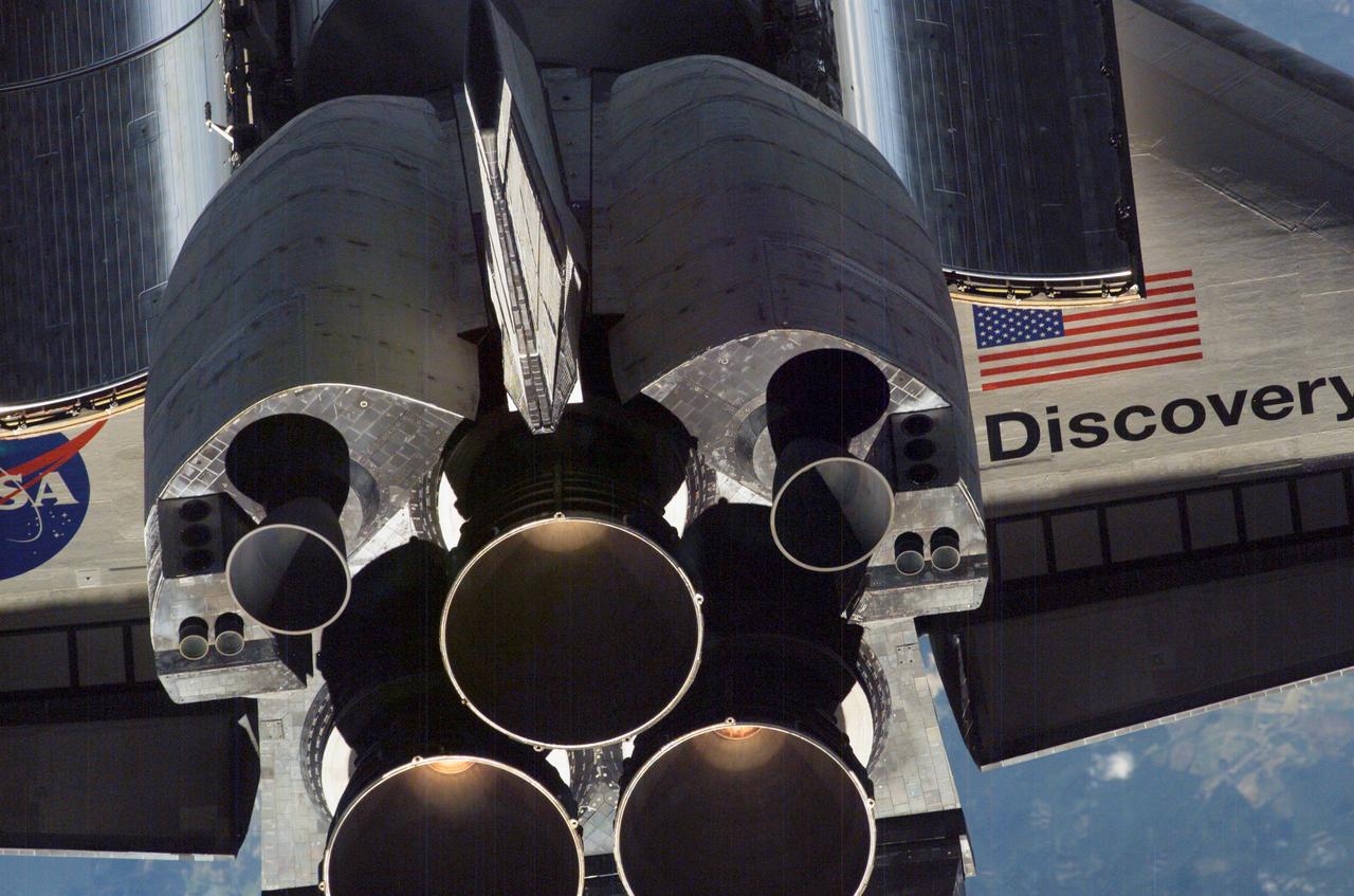
ISS013-E-47643 (6 July 2006) --- A close-up view of Space Shuttle Discovery's tail section is featured in this image photographed by an Expedition 13 crewmember on the International Space Station during RPM survey. Visible are the shuttle's main engines, vertical stabilizer, orbital maneuvering system (OMS) pods and a portion of the aft cargo bay and wings.
ISS013-E-47629 (6 July 2006) --- A close-up view of Space Shuttle Discovery's tail section is featured in this image photographed by an Expedition 13 crewmember on the International Space Station during STS-121 R-Pitch Maneuver survey on Flight Day 3. Visible are the shuttle's main engines, vertical stabilizer, orbital maneuvering system (OMS) pods, reaction control system (RCS) jets and a portion of payload bay door radiator and wings.
The load pad bonding process for the vertical tails was a preliminary step in the process to test the F/A-18E from the Naval Air Systems Command (NAVAIR) in Patuxent River, Maryland. The aircraft is in NASA’s Armstrong Flight Research Center Flight Loads Laboratory in Edwards, California, for the center’s biggest load calibrations tests. This testing is needed before the aircraft can serve as a test vehicle for determining if it can safely manage maneuvers and proposed upgrades.
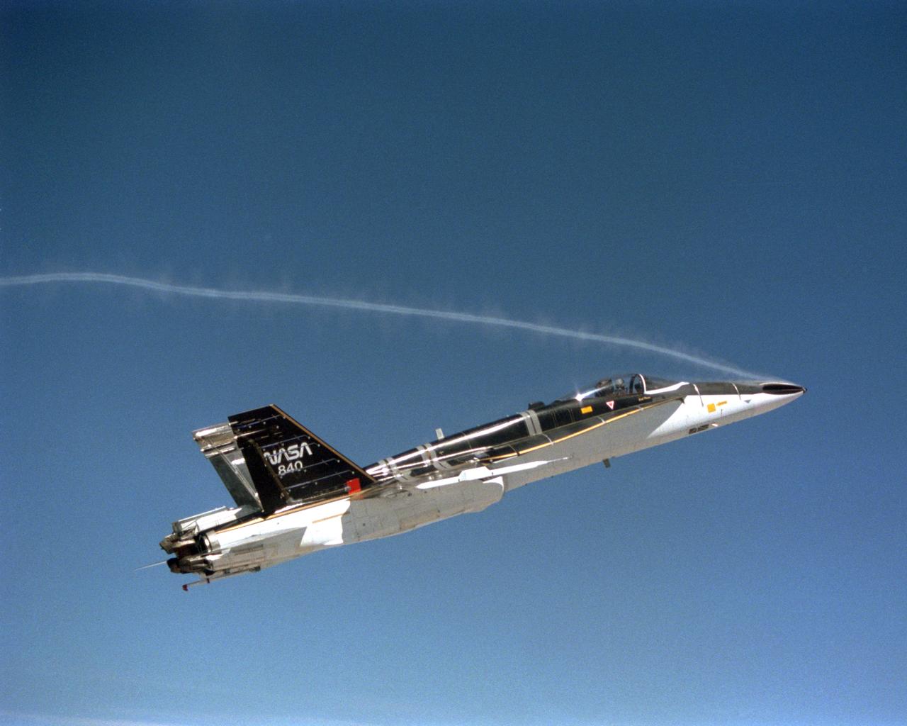
During the final phase of tests with the HARV, Dryden technicians installed nose strakes, which were panels that fitted flush against the sides of the forward nose. When the HARV was at a high alpha, the aerodynamics of the nose caused a loss of directional stability. Extending one or both of the strakes results in strong side forces that, in turn, generated yaw control. This approach, along with the aircraft's Thrust Vectoring Control system, proved to be stability under flight conditions in which conventional surfaces, such as the vertical tails, were ineffective.
The load pad bonding process for the vertical tails was a preliminary step in the process to test the F/A-18E from the Naval Air Systems Command (NAVAIR) in Patuxent River, Maryland. The aircraft is in NASA’s Armstrong Flight Research Center Flight Loads Laboratory in Edwards, California, for the center’s biggest load calibrations tests. This testing is needed before the aircraft can serve as a test vehicle for determining if it can safely manage maneuvers and proposed upgrades.
A close-up view of Space Shuttle Discovery's tail section is featured in this image photographed by an Expedition 13 crew member on the International Space Station (ISS) during the STS-121 Rotating Pitch Maneuver (RPM) survey. Visible are the space shuttle's main engines (SSME), vertical stabilizer, orbital maneuvering system (OMS) pods and a portion of the aft cargo bay and wings. The Marshall Space Flight Center (MSFC) has management responsibility for development of the SSME.

The load pad bonding process for the vertical tails was a preliminary step in the process to test the F/A-18E from the Naval Air Systems Command (NAVAIR) in Patuxent River, Maryland. The aircraft is in NASA’s Armstrong Flight Research Center Flight Loads Laboratory in Edwards, California, for the center’s biggest load calibrations tests. This testing is needed before the aircraft can serve as a test vehicle for determining if it can safely manage maneuvers and proposed upgrades.
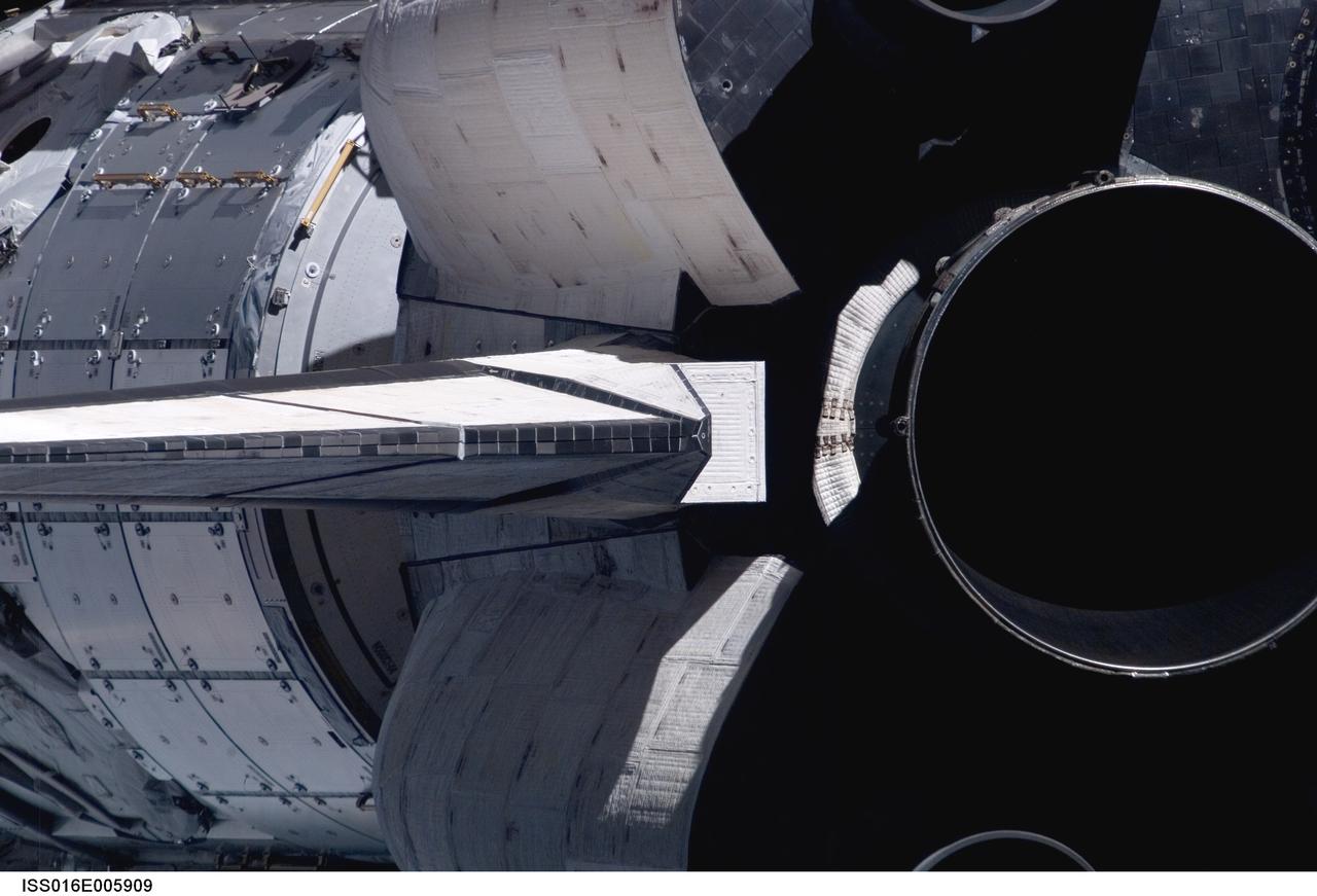
ISS016-E-005909 (25 Oct. 2007) --- A close-up view of Space Shuttle Discovery's tail section is featured in this image photographed by an Expedition 16 crewmember during a backflip maneuver performed by the approaching visitors (STS-120) to the International Space Station. The image provides partial views of the shuttle's main engines, orbital maneuvering system (OMS) pods, vertical stabilizer and the Harmony node in the payload bay.
The load pad bonding process for the vertical tails was a preliminary step in the process to test the F/A-18E from the Naval Air Systems Command (NAVAIR) in Patuxent River, Maryland. The aircraft is in NASA’s Armstrong Flight Research Center Flight Loads Laboratory in Edwards, California, for the center’s biggest load calibrations tests. This testing is needed before the aircraft can serve as a test vehicle for determining if it can safely manage maneuvers and proposed upgrades.
The load pad bonding process for the vertical tails was a preliminary step in the process to test the F/A-18E from the Naval Air Systems Command (NAVAIR) in Patuxent River, Maryland. The aircraft is in NASA’s Armstrong Flight Research Center Flight Loads Laboratory in Edwards, California, for the center’s biggest load calibrations tests. This testing is needed before the aircraft can serve as a test vehicle for determining if it can safely manage maneuvers and proposed upgrades.
The load pad bonding process for the vertical tails was a preliminary step in the process to test the F/A-18E from the Naval Air Systems Command (NAVAIR) in Patuxent River, Maryland. The aircraft is in NASA’s Armstrong Flight Research Center Flight Loads Laboratory in Edwards, California, for the center’s biggest load calibrations tests. This testing is needed before the aircraft can serve as a test vehicle for determining if it can safely manage maneuvers and proposed upgrades.
The load pad bonding process for the vertical tails was a preliminary step in the process to test the F/A-18E from the Naval Air Systems Command (NAVAIR) in Patuxent River, Maryland. The aircraft is in NASA’s Armstrong Flight Research Center Flight Loads Laboratory in Edwards, California, for the center’s biggest load calibrations tests. This testing is needed before the aircraft can serve as a test vehicle for determining if it can safely manage maneuvers and proposed upgrades.
The load pad bonding process for the vertical tails was a preliminary step in the process to test the F/A-18E from the Naval Air Systems Command (NAVAIR) in Patuxent River, Maryland. The aircraft is in NASA’s Armstrong Flight Research Center Flight Loads Laboratory in Edwards, California, for the center’s biggest load calibrations tests. This testing is needed before the aircraft can serve as a test vehicle for determining if it can safely manage maneuvers and proposed upgrades.
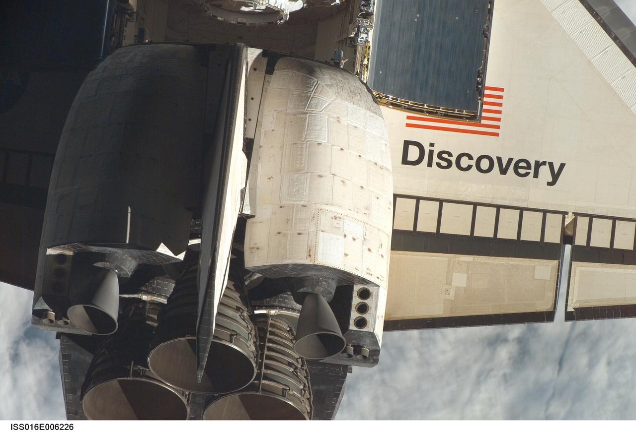
ISS016-E-006226 (25 Oct. 2007) --- Space Shuttle Discovery's tail section is featured in this close-up image photographed by an Expedition 16 crewmember during a backflip maneuver performed by the approaching visitors (STS-120) to the International Space Station. The image provides partial views of the shuttle's main engines, starboard wing section, orbital maneuvering system (OMS) pods, vertical stabilizer and payload bay door panels.
The load pad bonding process for the vertical tails was a preliminary step in the process to test the F/A-18E from the Naval Air Systems Command (NAVAIR) in Patuxent River, Maryland. The aircraft is in NASA’s Armstrong Flight Research Center Flight Loads Laboratory in Edwards, California, for the center’s biggest load calibrations tests. This testing is needed before the aircraft can serve as a test vehicle for determining if it can safely manage maneuvers and proposed upgrades.
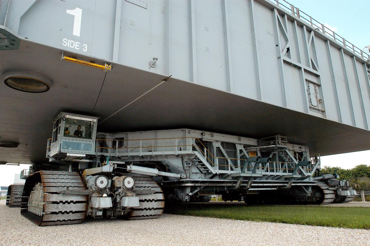
KENNEDY SPACE CENTER, FLA. - A closeup of crawler-transporter (CT) number 2 shows the cab (left, above the tracks) that recently underwent modifications. The CT is transporting a Mobile Launch Platform (MLP) on a test run to the pad. The CT moves Space Shuttle vehicles, situated on the MLP, between the VAB and launch pad. Moving on four double-tracked crawlers, the CT uses a laser guidance system and a leveling system for the journey that keeps the top of a Space Shuttle vertical within plus- or minus-10 minutes of arc. The system enables the CT-MLP-Shuttle to negotiate the ramp leading to the launch pads and keep the load level. Unloaded, the CT weighs 6 million pounds. Seen on top of the MLP are two tail service masts that support the fluid, gas and electrical requirements of the orbiter’s liquid oxygen and liquid hydrogen aft umbilicals.
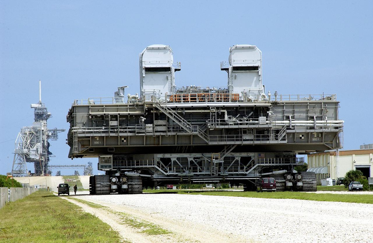
KENNEDY SPACE CENTER, FLA. - Crawler-transporter (CT) number 2 nears the launch pad with a Mobile Launcher Platform (MLP) on top. After recent modifications to the cab and muffler system, the CT was taken on a test run. The CT moves Space Shuttle vehicles, situated on the MLP, between the VAB and launch pad. Moving on four double-tracked crawlers, the CT uses a laser guidance system and a leveling system for the journey that keeps the top of a Space Shuttle vertical within plus- or minus-10 minutes of arc. The system enables the CT-MLP-Shuttle to negotiate the ramp leading to the launch pads and keep the load level. Unloaded, the CT weighs 6 million pounds. Seen on top of the MLP are two tail service masts that support the fluid, gas and electrical requirements of the orbiter’s liquid oxygen and liquid hydrogen aft umbilicals.
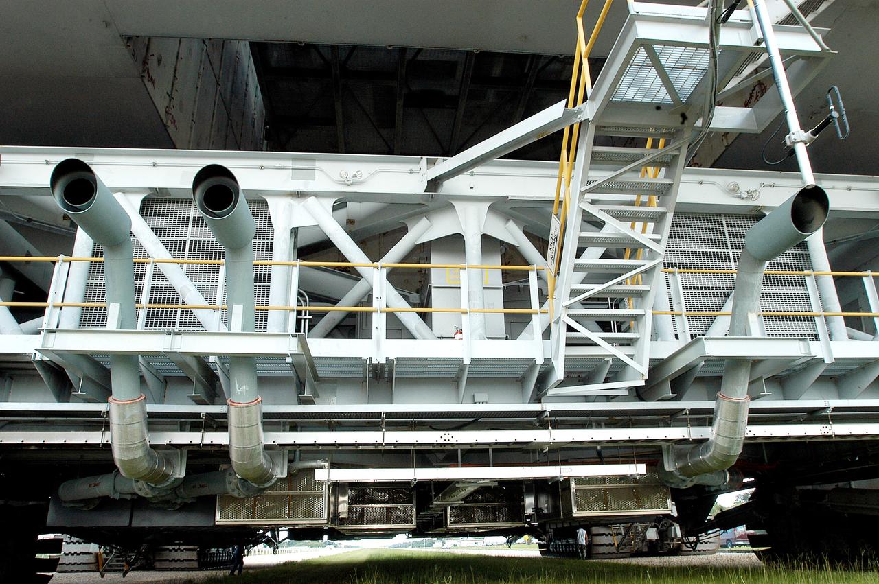
KENNEDY SPACE CENTER, FLA. - A closeup of crawler-transportation (CT) number 2 shows the new muffler system on the vehicle. The CT also recently underwent modifications to the cab. The CT is transporting a Mobile Launch Platform (MLP). The CT moves Space Shuttle vehicles, situated on the MLP, between the VAB and launch pad. Moving on four double-tracked crawlers, the CT uses a laser guidance system and a leveling system for the journey that keeps the top of a Space Shuttle vertical within plus- or minus-10 minutes of arc. The system enables the CT-MLP-Shuttle to negotiate the ramp leading to the launch pads and keep the load level. Unloaded, the CT weighs 6 million pounds. Seen on top of the MLP are two tail service masts that support the fluid, gas and electrical requirements of the orbiter’s liquid oxygen and liquid hydrogen aft umbilicals.
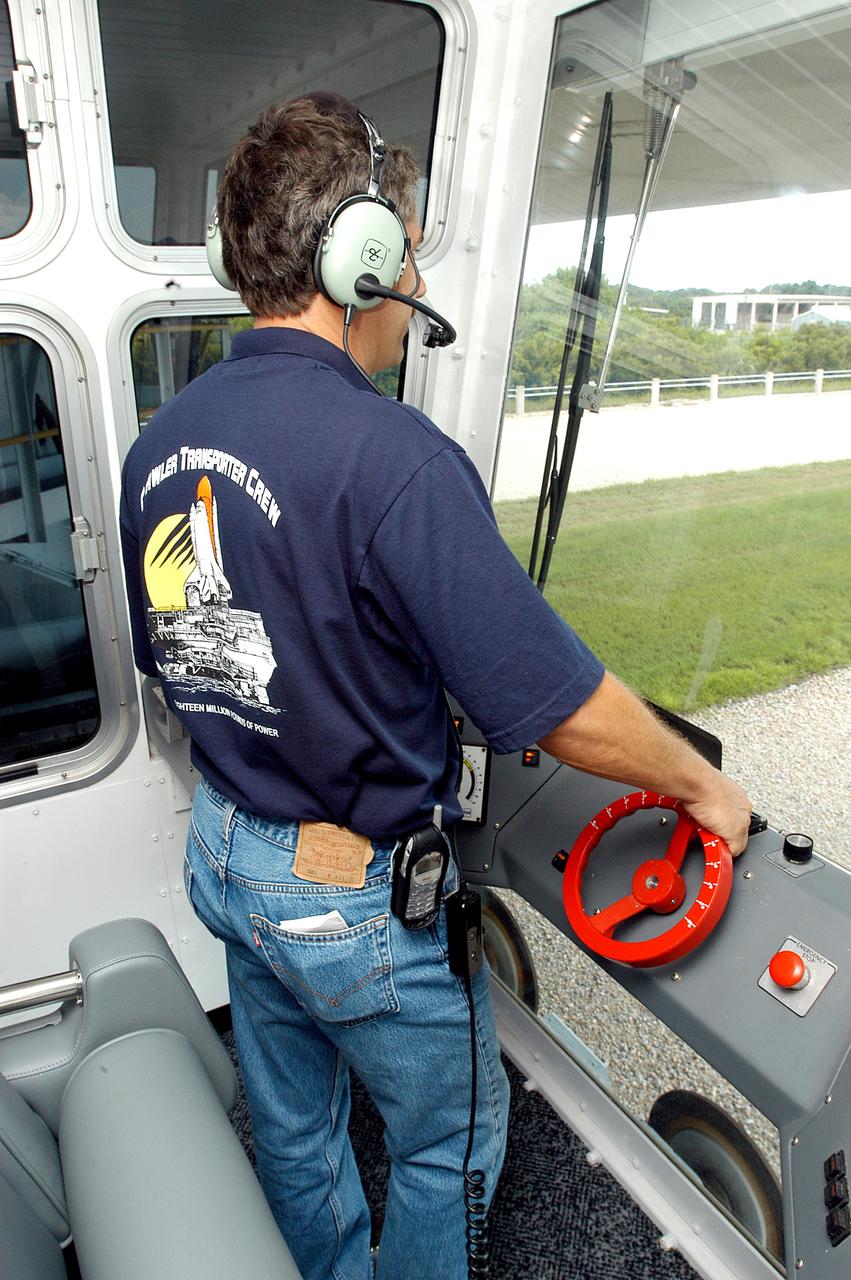
KENNEDY SPACE CENTER, FLA. - Inside the cab of crawler-transporter (CT) number 2, driver Sam Dove, with United Space Alliance, operates the vehicle on a test run to the launch pad. The CT recently underwent modifications to the cab. The CT is transporting a Mobile Launch Platform (MLP). The CT moves Space Shuttle vehicles, situated on the MLP, between the VAB and launch pad. Moving on four double-tracked crawlers, the CT uses a laser guidance system and a leveling system for the journey that keeps the top of a Space Shuttle vertical within plus- or minus-10 minutes of arc. The system enables the CT-MLP-Shuttle to negotiate the ramp leading to the launch pads and keep the load level. Unloaded, the CT weighs 6 million pounds. Seen on top of the MLP are two tail service masts that support the fluid, gas and electrical requirements of the orbiter’s liquid oxygen and liquid hydrogen aft umbilicals.
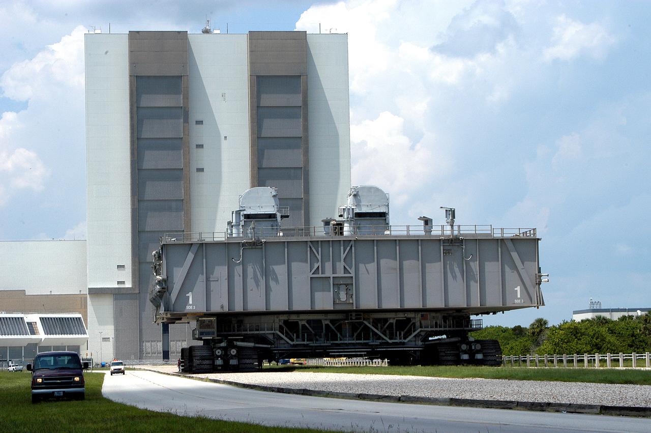
KENNEDY SPACE CENTER, FLA. - Crawler-transporter (CT) number 2, moves away from the Vehicle Assembly Building with a Mobile Launcher Platform (MLP) on top on a test run to the launch pad. The CT recently underwent modifications to the cab. The CT moves Space Shuttle vehicles, situated on the MLP, between the VAB and launch pad. Moving on four double-tracked crawlers, the CT uses a laser guidance system and a leveling system for the journey that keeps the top of a Space Shuttle vertical within plus- or minus-10 minutes of arc. The system enables the CT-MLP-Shuttle to negotiate the ramp leading to the launch pads and keep the load level. Unloaded, the CT weighs 6 million pounds. Seen on top of the MLP are two tail service masts that support the fluid, gas and electrical requirements of the orbiter’s liquid oxygen and liquid hydrogen aft umbilicals.
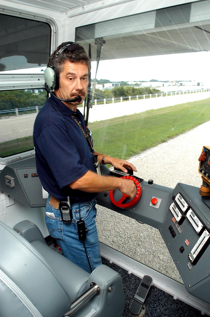
KENNEDY SPACE CENTER, FLA. - Inside the cab of crawler-transporter (CT) number 2, driver Sam Dove, with United Space Alliance, operates the vehicle on a test run to the launch pad. The CT recently underwent modifications to the cab. The CT is transporting a Mobile Launch Platform (MLP). The CT moves Space Shuttle vehicles, situated on the MLP, between the VAB and launch pad. Moving on four double-tracked crawlers, the CT uses a laser guidance system and a leveling system for the journey that keeps the top of a Space Shuttle vertical within plus- or minus-10 minutes of arc. The system enables the CT-MLP-Shuttle to negotiate the ramp leading to the launch pads and keep the load level. Unloaded, the CT weighs 6 million pounds. Seen on top of the MLP are two tail service masts that support the fluid, gas and electrical requirements of the orbiter’s liquid oxygen and liquid hydrogen aft umbilicals.
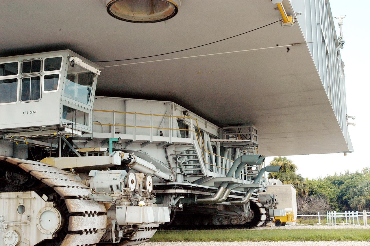
KENNEDY SPACE CENTER, FLA. - A closeup of crawler-transporter (CT) number 2 shows the cab, at left, that recently underwent modifications. The CT is transporting a Mobile Launch Platform (MLP) on a test run to the pad. The CT moves Space Shuttle vehicles, situated on the MLP, between the VAB and launch pad. Moving on four double-tracked crawlers, the CT uses a laser guidance system and a leveling system for the journey that keeps the top of a Space Shuttle vertical within plus- or minus-10 minutes of arc. The system enables the CT-MLP-Shuttle to negotiate the ramp leading to the launch pads and keep the load level. Unloaded, the CT weighs 6 million pounds. Seen on top of the MLP are two tail service masts that support the fluid, gas and electrical requirements of the orbiter’s liquid oxygen and liquid hydrogen aft umbilicals.
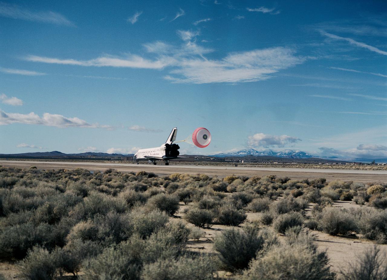
STS-53 Discovery, Orbiter Vehicle (OV) 103, is slowed by a red, white, and blue drag chute during its landing on concrete runway 22 at Edwards Air Force Base (EAFB), California. Main landing gear (MLG) touchdown occurred at 12:43:17 pm (Pacific Standard Time (PST)). This aft view of OV-103 shows the drag chute deployed from its compartment at the base of the vertical tail, the speedbrake/rudder flaps open, and the space shuttle main engines (SSMEs). Both MLG and nose landing gear (NLG) ride along the runway surface. Desert scrub brush appears in the foreground and mountains are seen in the background.
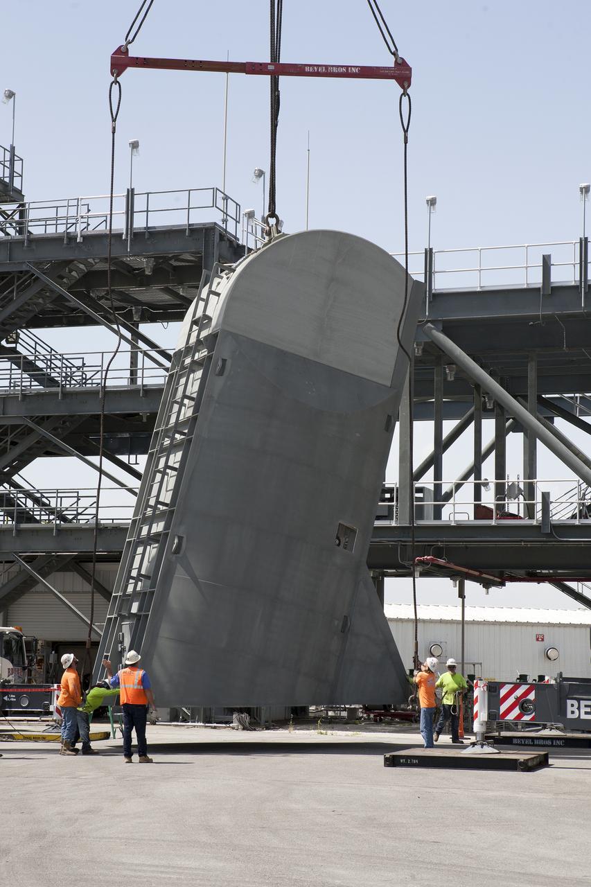
Technicians assist as a crane is used to lift the first Tail Service Mast Umbilical (TSMU) into the vertical position at the Launch Equipment Test Facility (LETF) at NASA’s Kennedy Space Center in Florida. Two TSMUs will provide liquid propellants and power to the Space Launch System (SLS) rocket’s core stage engine. Both TSMUs will connect to the zero-level deck on the mobile launcher, providing fuel and electricity to the SLS rocket before it launches on Exploration Mission 1. The TSMU will undergo testing and validation at the LETF to verify it is functioning properly. The center’s Engineering Directorate and the Ground Systems Development and Operations Program are overseeing processing and testing of the umbilicals.
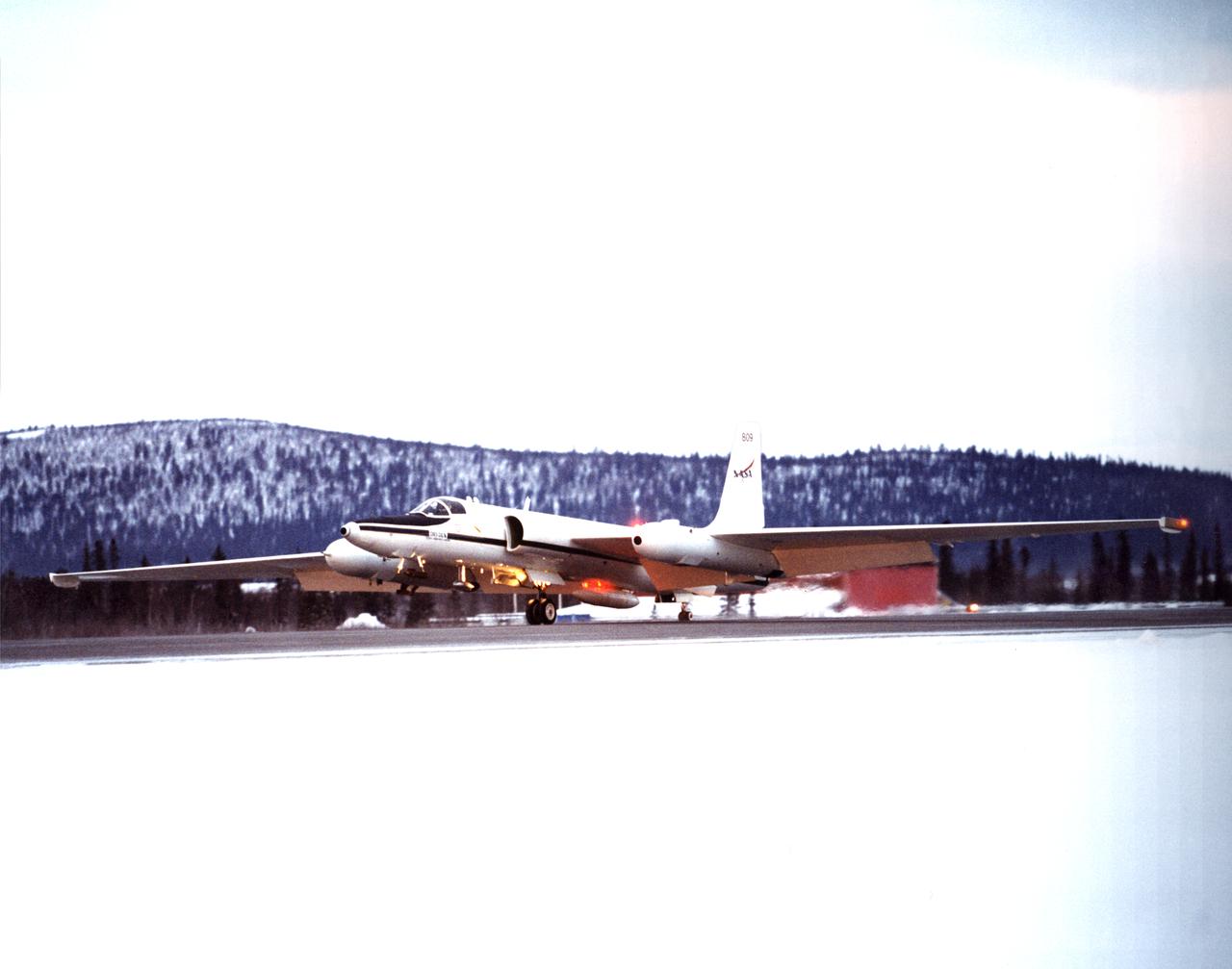
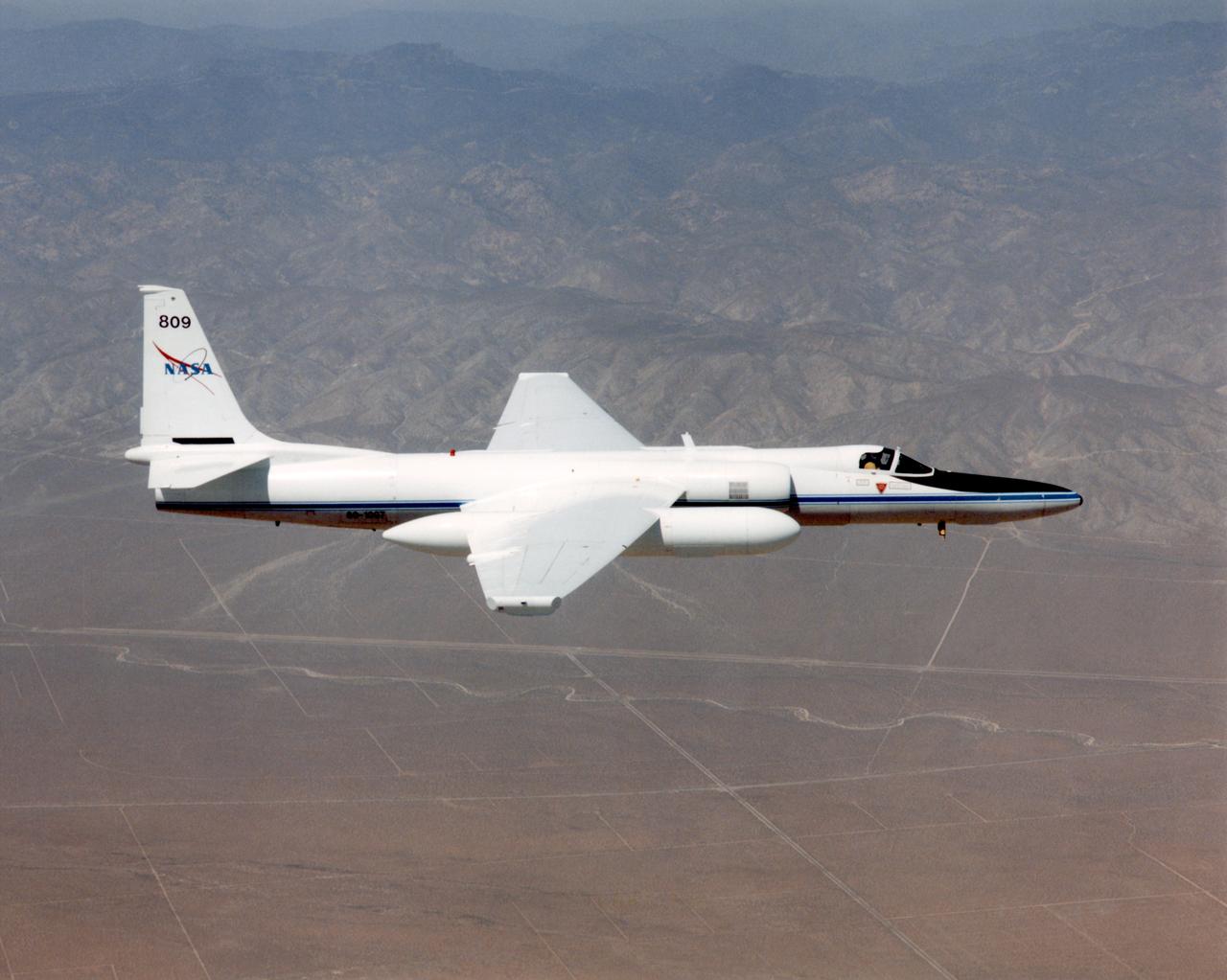
ER-2s bearing tail numbers 806 and 809 are used as airborne science platforms by NASA's Dryden Flight Research Center. The aircraft are platforms for a variety of high-altitude science missions flown over various parts of the world. They are also used for earth science and atmospheric sensor research and development, satellite calibration and data validation. The ER-2s are capable of carrying a maximum payload of 2,600 pounds of experiments in a nose bay, the main equipment bay behind the cockpit, two wing-mounted superpods and small underbody and trailing edges. Most ER-2 missions last about six hours with ranges of about 2,200 nautical miles. The aircraft typically fly at altitudes above 65,000 feet. On November 19, 1998, an ER-2 set a world record for medium weight aircraft reaching an altitude of 68,700 feet. The aircraft is 63 feet long, with a wingspan of 104 feet. The top of the vertical tail is 16 feet above ground when the aircraft is on the bicycle-type landing gear. Cruising speeds are 410 knots, or 467 miles per hour, at altitude. A single General Electric F-118 turbofan engine rated at 17,000 pounds thrust powers the ER-2.

ER-2s bearing tail numbers 806 and 809 are used as airborne science platforms by NASA's Dryden Flight Research Center. The aircraft are platforms for a variety of high-altitude science missions flown over various parts of the world. They are also used for earth science and atmospheric sensor research and development, satellite calibration and data validation. The ER-2s are capable of carrying a maximum payload of 2,600 pounds of experiments in a nose bay, the main equipment bay behind the cockpit, two wing-mounted superpods and small underbody and trailing edges. Most ER-2 missions last about six hours with ranges of about 2,200 nautical miles. The aircraft typically fly at altitudes above 65,000 feet. On November 19, 1998, an ER-2 set a world record for medium weight aircraft reaching an altitude of 68,700 feet. The aircraft is 63 feet long, with a wingspan of 104 feet. The top of the vertical tail is 16 feet above ground when the aircraft is on the bicycle-type landing gear. Cruising speeds are 410 knots, or 467 miles per hour, at altitude. A single General Electric F-118 turbofan engine rated at 17,000 pounds thrust powers the ER-2.
ER-2s bearing tail numbers 806 and 809 are used as airborne science platforms by NASA's Dryden Flight Research Center. The aircraft are platforms for a variety of high-altitude science missions flown over various parts of the world. They are also used for earth science and atmospheric sensor research and development, satellite calibration and data validation. The ER-2s are capable of carrying a maximum payload of 2,600 pounds of experiments in a nose bay, the main equipment bay behind the cockpit, two wing-mounted superpods and small underbody and trailing edges. Most ER-2 missions last about six hours with ranges of about 2,200 nautical miles. The aircraft typically fly at altitudes above 65,000 feet. On November 19, 1998, an ER-2 set a world record for medium weight aircraft reaching an altitude of 68,700 feet. The aircraft is 63 feet long, with a wingspan of 104 feet. The top of the vertical tail is 16 feet above ground when the aircraft is on the bicycle-type landing gear. Cruising speeds are 410 knots, or 467 miles per hour, at altitude. A single General Electric F-118 turbofan engine rated at 17,000 pounds thrust powers the ER-2.

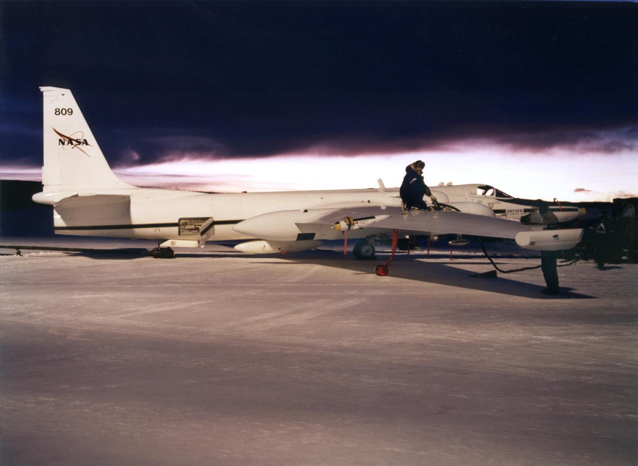
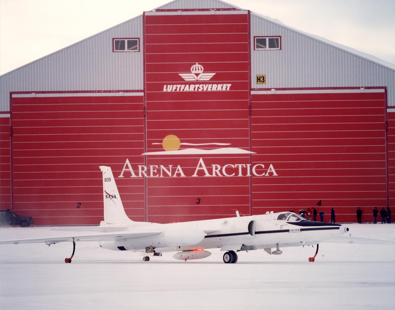
ER-2 tail number 809, is one of two Airborne Science ER-2s used as science platforms by Dryden. The aircraft are platforms for a variety of high-altitude science missions flown over various parts of the world. They are also used for earth science and atmospheric sensor research and development, satellite calibration and data validation. The ER-2s are capable of carrying a maximum payload of 2,600 pounds of experiments in a nose bay, the main equipment bay behind the cockpit, two wing-mounted superpods and small underbody and trailing edges. Most ER-2 missions last about six hours with ranges of about 2,200 nautical miles. The aircraft typically fly at altitudes above 65,000 feet. On November 19, 1998, the ER-2 set a world record for medium weight aircraft reaching an altitude of 68,700 feet. The aircraft is 63 feet long, with a wingspan of 104 feet. The top of the vertical tail is 16 feet above ground when the aircraft is on the bicycle-type landing gear. Cruising speeds are 410 knots, or 467 miles per hour, at altitude. A single General Electric F118 turbofan engine rated at 17,000 pounds thrust powers the ER-2.

ER-2 tail number 806, is one of two Airborne Science ER-2s used as science platforms by Dryden. The aircraft are platforms for a variety of high-altitude science missions flown over various parts of the world. They are also used for earth science and atmospheric sensor research and development, satellite calibration and data validation. The ER-2s are capable of carrying a maximum payload of 2,600 pounds of experiments in a nose bay, the main equipment bay behind the cockpit, two wing-mounted superpods and small underbody and trailing edges. Most ER-2 missions last about six hours with ranges of about 2,200 nautical miles. The aircraft typically fly at altitudes above 65,000 feet. On November 19, 1998, the ER-2 set a world record for medium weight aircraft reaching an altitude of 68,700 feet. The aircraft is 63 feet long, with a wingspan of 104 feet. The top of the vertical tail is 16 feet above ground when the aircraft is on the bicycle-type landing gear. Cruising speeds are 410 knots, or 467 miles per hour, at altitude. A single General Electric F-118 turbofan engine rated at 17,000 pounds thrust powers the ER-2.

ER-2 tail number 806, is one of two Airborne Science ER-2s used as science platforms by Dryden. The aircraft are platforms for a variety of high-altitude science missions flown over various parts of the world. They are also used for earth science and atmospheric sensor research and development, satellite calibration and data validation. The ER-2s are capable of carrying a maximum payload of 2,600 pounds of experiments in a nose bay, the main equipment bay behind the cockpit, two wing-mounted superpods and small underbody and trailing edges. Most ER-2 missions last about six hours with ranges of about 2,200 nautical miles. The aircraft typically fly at altitudes above 65,000 feet. On November 19, 1998, the ER-2 set a world record for medium weight aircraft reaching an altitude of 68,700 feet. The aircraft is 63 feet long, with a wingspan of 104 feet. The top of the vertical tail is 16 feet above ground when the aircraft is on the bicycle-type landing gear. Cruising speeds are 410 knots, or 467 miles per hour, at altitude. A single General Electric F-118 turbofan engine rated at 17,000 pounds thrust powers the ER-2.
ER-2s bearing tail numbers 806 and 809 are used as airborne science platforms by NASA's Dryden Flight Research Center. The aircraft are platforms for a variety of high-altitude science missions flown over various parts of the world. They are also used for earth science and atmospheric sensor research and development, satellite calibration and data validation. The ER-2s are capable of carrying a maximum payload of 2,600 pounds of experiments in a nose bay, the main equipment bay behind the cockpit, two wing-mounted superpods and small underbody and trailing edges. Most ER-2 missions last about six hours with ranges of about 2,200 nautical miles. The aircraft typically fly at altitudes above 65,000 feet. On November 19, 1998, an ER-2 set a world record for medium weight aircraft reaching an altitude of 68,700 feet. The aircraft is 63 feet long, with a wingspan of 104 feet. The top of the vertical tail is 16 feet above ground when the aircraft is on the bicycle-type landing gear. Cruising speeds are 410 knots, or 467 miles per hour, at altitude. A single General Electric F-118 turbofan engine rated at 17,000 pounds thrust powers the ER-2.
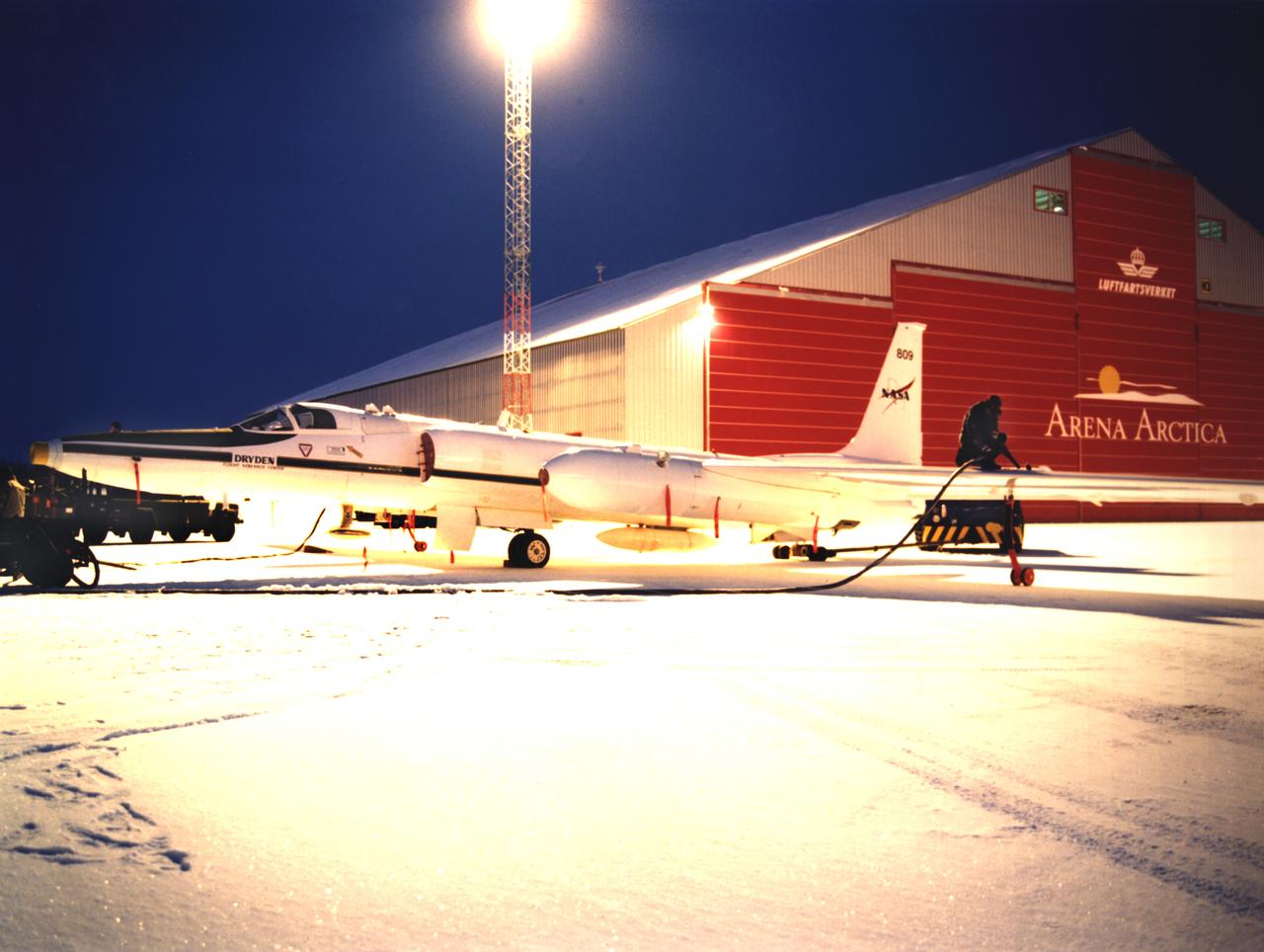
ER-2C tail number 809, was one of two Airborne Science ER-2Cs used as science platforms by Dryden. The aircraft were platforms for a variety of high-altitude science missions flown over various parts of the world. They were also used for earth science and atmospheric sensor research and development, satellite calibration and data validation. The ER-2Cs were capable of carrying a maximum payload of 2,600 pounds of experiments in a nose bay, the main equipment bay behind the cockpit, two wing-mounted superpods and small underbody and trailing edges. Most ER-2C missions lasted about six hours with ranges of about 2,200 nautical miles. The aircraft typically flew at altitudes above 65,000 feet. On November 19, 1998, the ER-2C set a world record for medium weight aircraft reaching an altitude of 68,700 feet. The aircraft was 63 feet long, with a wingspan of 104 feet. The top of the vertical tail was 16 feet above ground when the aircraft was on the bicycle-type landing gear. Cruising speeds were 410 knots, or 467 miles per hour, at altitude. A single General Electric F-118 turbofan engine rated at 17,000 pounds thrust powers the ER-2C.

ER-2 tail number 806, is one of two Airborne Science ER-2s used as science platforms by Dryden. The aircraft are platforms for a variety of high-altitude science missions flown over various parts of the world. They are also used for earth science and atmospheric sensor research and development, satellite calibration and data validation. The ER-2s are capable of carrying a maximum payload of 2,600 pounds of experiments in a nose bay, the main equipment bay behind the cockpit, two wing-mounted superpods and small underbody and trailing edges. Most ER-2 missions last about six hours with ranges of about 2,200 nautical miles. The aircraft typically fly at altitudes above 65,000 feet. On November 19, 1998, the ER-2 set a world record for medium weight aircraft reaching an altitude of 68,700 feet. The aircraft is 63 feet long, with a wingspan of 104 feet. The top of the vertical tail is 16 feet above ground when the aircraft is on the bicycle-type landing gear. Cruising speeds are 410 knots, or 467 miles per hour, at altitude. A single General Electric F-118 turbofan engine rated at 17,000 pounds thrust powers the ER-2.
ER-2s bearing tail numbers 806 and 809 are used as airborne science platforms by NASA's Dryden Flight Research Center. The aircraft are platforms for a variety of high-altitude science missions flown over various parts of the world. They are also used for earth science and atmospheric sensor research and development, satellite calibration and data validation. The ER-2s are capable of carrying a maximum payload of 2,600 pounds of experiments in a nose bay, the main equipment bay behind the cockpit, two wing-mounted superpods and small underbody and trailing edges. Most ER-2 missions last about six hours with ranges of about 2,200 nautical miles. The aircraft typically fly at altitudes above 65,000 feet. On November 19, 1998, an ER-2 set a world record for medium weight aircraft reaching an altitude of 68,700 feet. The aircraft is 63 feet long, with a wingspan of 104 feet. The top of the vertical tail is 16 feet above ground when the aircraft is on the bicycle-type landing gear. Cruising speeds are 410 knots, or 467 miles per hour, at altitude. A single General Electric F-118 turbofan engine rated at 17,000 pounds thrust powers the ER-2.
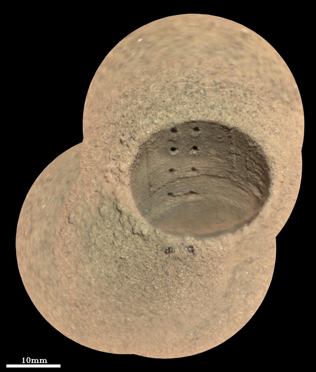
This composite image, made from four taken by the SuperCam instrument aboard NASA's Perseverance rover on August 8, 2021, shows the hole in a Martian rock where the rover attempted to collect its first sample; the small pits within it were created by laser zaps from SuperCam during subsequent efforts to analyze the rock's composition. The rover science team has nicknamed the drill hole "Roubion." The team believes that because of this rock's unusual composition, the process of extracting a core created a significant pile of tailings (or cuttings) around the coring hole. Eight pits produced by 30 laser shots each are seen in two columns inside the drill hole. The SuperCam team's analysis suggests that the top six pits penetrated the compacted mound of tailings around the hole, while the bottom two pits in the hole interrogated material below the rock surface. Two additional laser pits can be seen in the tailings at the near side of the hole. Two vertical ridges inside the hole – one on each side of the laser pits – were produced as the drill was removed, prior to laser analysis. Some bright mineral grains can be seen as glints in the tailings and in the drill hole. A few clumps or larger pieces of material are seen at the top of the tailings pile just to the left of the hole. The SuperCam images were taken from a distance of 7.32 feet (2.23 meters). A scale bar is included in this image. Perseverance landed in Mars' Jezero Crater on February 18, 2021, and has been exploring the floor of the crater since. At the time these images were taken, Perseverance was in an area nicknamed the "Crater Floor Fractured Rough" area. SuperCam is led by Los Alamos National Laboratory in New Mexico, where the instrument's Body Unit was developed. That part of the instrument includes several spectrometers as well as control electronics and software. The Mast Unit, including the Remote Microscopic Imager used for these images, was developed and built by several laboratories of the CNRS (the French research center) and French universities under the contracting authority of Centre National d'Etudes Spatiales (CNES, the French space agency). A key objective for Perseverance's mission on Mars is astrobiology, including the search for signs of ancient microbial life. The rover will characterize the planet's geology and past climate, pave the way for human exploration of the Red Planet, and be the first mission to collect and cache Martian rock and regolith (broken rock and dust). Subsequent NASA missions, in cooperation with ESA (European Space Agency), would send spacecraft to Mars to collect these sealed samples from the surface and return them to Earth for in-depth analysis. The Mars 2020 Perseverance mission is part of NASA's Moon to Mars exploration approach, which includes Artemis missions to the Moon that will help prepare for human exploration of the Red Planet. Movie available at https://photojournal.jpl.nasa.gov/catalog/PIA24749
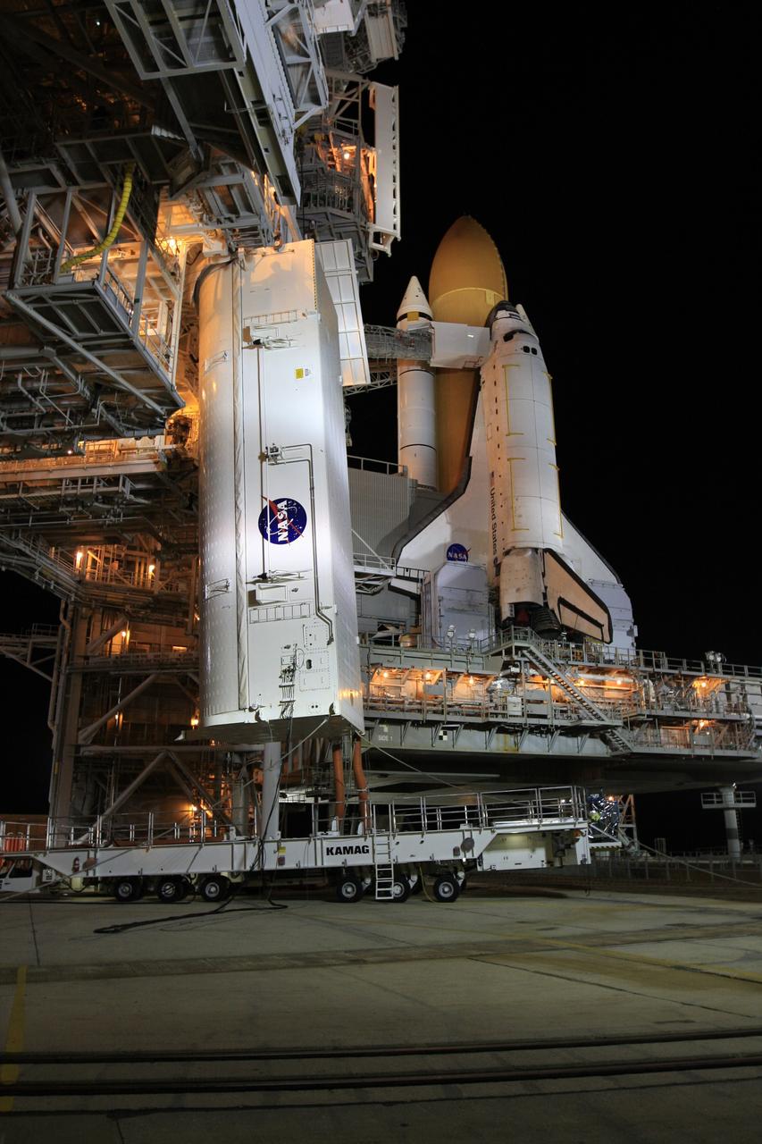
CAPE CANAVERAL, Fla. - At Launch Pad 39A at NASA's Kennedy Space Center in Florida, the payload canister, at left, is lifted from its transporter toward the payload changeout room in the rotating service structure. The canister carries a cargo of four carriers holding various equipment for the STS-125 mission aboard space shuttle Atlantis to service NASA’s Hubble Space Telescope. Atlantis is seen at right, atop the mobile launcher platform. The two tail service masts flank the engines in front of the wings. At the pad, the cargo will be moved into the Payload Changeout Room. The changeout room is the enclosed, environmentally controlled portion of the rotating service structure that supports cargo delivery to the pad and subsequent vertical installation into the shuttle’s payload bay. Launch of Atlantis is targeted for Oct. 10. Photo credit: NASA/Troy Cryder
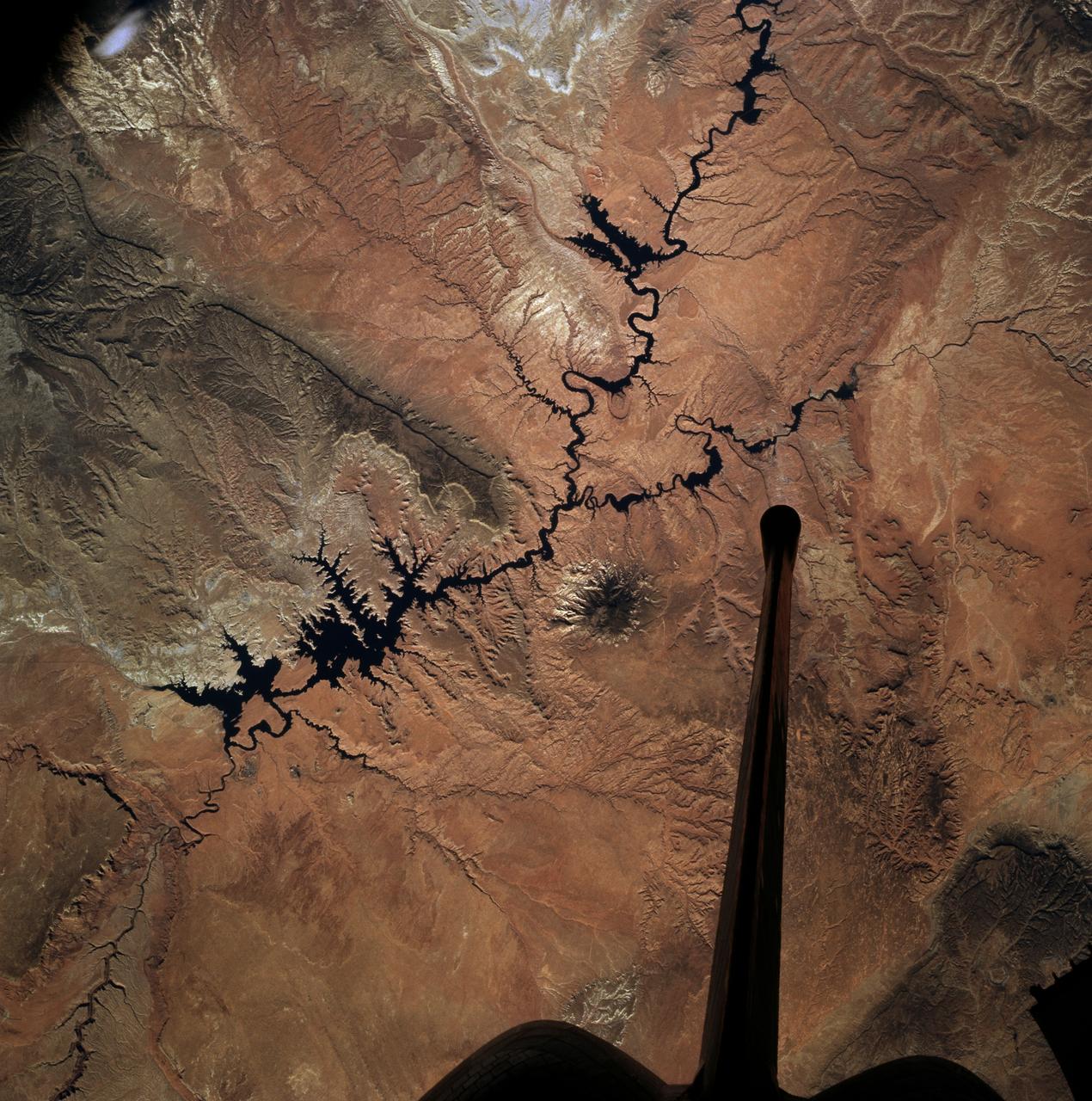
STS073-727-045 (21 October 1995) --- Photographed by the astronauts aboard the Space Shuttle Columbia is this scene over Lake Powell. The lake was formed by the Glen Canyon Dam on the Colorado River. The vertical stabilizer of Columbia points northeastward. Navaho Mountain, northwest of the tail, according to NASA geologists, was formed by an intrusion of molten rock that uplifted older, layered rocks, then cooled, and has been exposed by erosion. The rest of the landscape is dominated by faulted layers of sandstone, shale, and limestone that were formed in shallow seas and great deserts 80 to 250 million years ago. These rocks of the Colorado Plateau were uplifted a few million years ago to be dissected by the meandering Colorado River, San Juan River, and their tributaries.
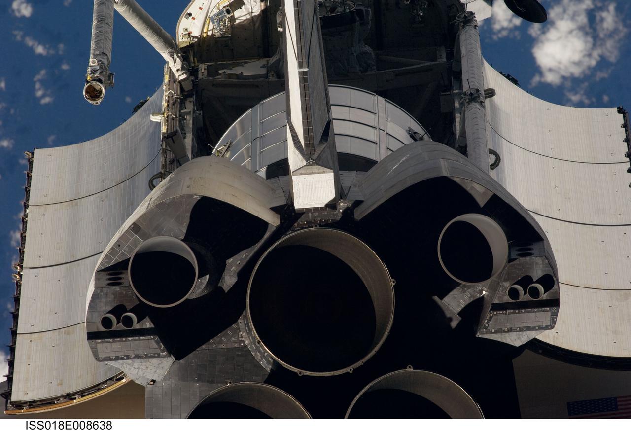
ISS018-E-008638 (16 Nov. 2008) --- A close-up view of Space Shuttle Endeavour's tail section was provided by Expedition 18 crewmembers on the International Space Station. The image provides partial views of the shuttle's main engines, orbital maneuvering system (OMS) pods, vertical stabilizer, the payload bay door panels and the Leonard Multi-Purpose Logistics Module located in the cargo bay. Before docking with the station, astronaut Chris Ferguson, STS-126 commander, flew the shuttle through a roll pitch maneuver or basically a backflip to allow the space station crew a good view of Endeavour's heat shield. Using digital still cameras equipped with both 400 and 800 millimeter lenses, the ISS crewmembers took a number of photos of the shuttle's thermal protection system and sent them down to teams on the ground for analysis. A 400 millimeter lens was used for this image.
CAPE CANAVERAL, Fla. - At Launch Pad 39A at NASA's Kennedy Space Center in Florida, the payload canister arrives beneath the payload changeout room in the rotating service structure (left). Space shuttle Atlantis is at right. The two tail service masts on the mobile launcher platform flank the engines in front of the wings. The canister carries a cargo of four carriers holding various equipment for the STS-125 mission aboard Atlantis to service NASA’s Hubble Space Telescope. At the pad, the cargo will be moved into the Payload Changeout Room. The changeout room is the enclosed, environmentally controlled portion of the rotating service structure that supports cargo delivery to the pad and subsequent vertical installation into the shuttle’s payload bay. Launch of Atlantis is targeted for Oct. 10. Photo credit: NASA/Troy Cryder
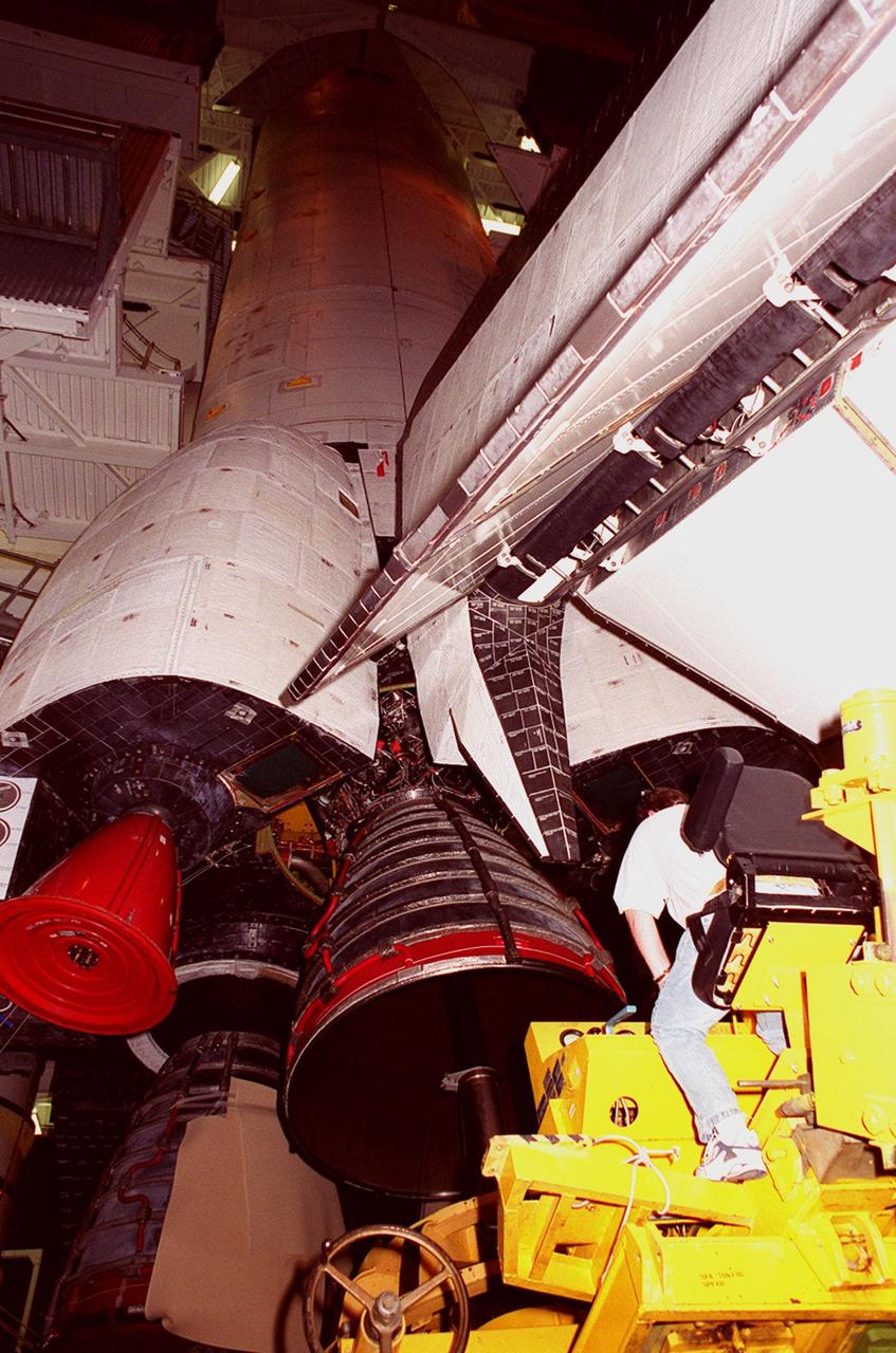
KENNEDY SPACE CENTER, FLA. -- Underneath the 26.3-foot vertical tail structure of Space Shuttle Atlantis, a worker in the Vehicle Assembly Building maneuvers equipment under Main Engine No. 1 in order to remove it. An inventory review concerning defective main engine fuel pump tip seals indicated that defective seals may be present on the fuel pump for the engine. The decision was made to replace the suspect engine with one originally slated for Discovery. The main engine nozzles, visible in the photo, are 7.8 feet across and 9.4 feet high. Space Shuttle Atlantis is scheduled to launch no earlier than April 17, 2000, on mission STS-101 to resupply the International Space Station for the arrival of the next pressurized module, the Russian-built Zvezda

KENNEDY SPACE CENTER, FLA. -- Underneath the 26.3-foot vertical tail structure of Space Shuttle Atlantis, a worker in the Vehicle Assembly Building maneuvers equipment under Main Engine No. 1 in order to remove it. An inventory review concerning defective main engine fuel pump tip seals indicated that defective seals may be present on the fuel pump for the engine. The decision was made to replace the suspect engine with one originally slated for Discovery. The main engine nozzles, visible in the photo, are 7.8 feet across and 9.4 feet high. Space Shuttle Atlantis is scheduled to launch no earlier than April 17, 2000, on mission STS-101 to resupply the International Space Station for the arrival of the next pressurized module, the Russian-built Zvezda
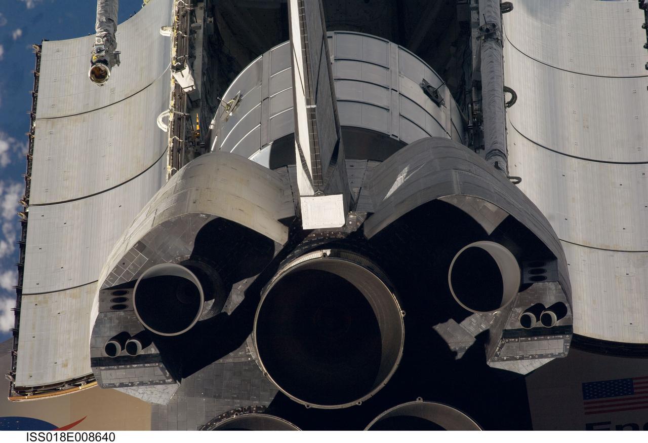
ISS018-E-008640 (16 Nov. 2008) --- A close-up view of Space Shuttle Endeavour's tail section was provided by Expedition 18 crewmembers on the International Space Station. The image provides partial views of the shuttle's main engines, orbital maneuvering system (OMS) pods, vertical stabilizer, the payload bay door panels and the Leonard Multi-Purpose Logistics Module located in the cargo bay. Before docking with the station, astronaut Chris Ferguson, STS-126 commander, flew the shuttle through a roll pitch maneuver or basically a backflip to allow the space station crew a good view of Endeavour's heat shield. Using digital still cameras equipped with both 400 and 800 millimeter lenses, the ISS crewmembers took a number of photos of the shuttle's thermal protection system and sent them down to teams on the ground for analysis. A 400 millimeter lens was used for this image.
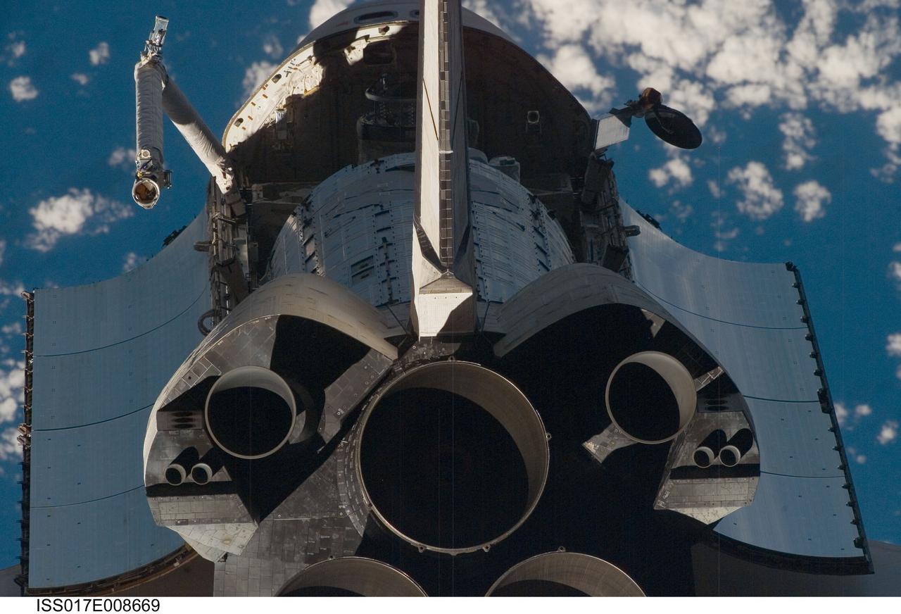
ISS017-E-008669 (2 June 2008) --- A close-up view of Space Shuttle Discovery's tail section was provided by Expedition 17 crewmembers on the International Space Station (ISS). The image provides partial views of the shuttle's main engines, orbital maneuvering system (OMS) pods, vertical stabilizer, the payload bay door panels and the second component of the Japan Aerospace Exploration Agency's Kibo laboratory, the Japanese Pressurized Module (JPM) located in the cargo bay. Before docking with the station, astronaut Mark Kelly, STS-124 commander, flew the shuttle through a roll pitch maneuver or basically a backflip to allow the space station crew a good view of Discovery's heat shield. Using digital still cameras equipped with both 400 and 800 millimeter lenses, the ISS crewmembers took a number of photos of the shuttle's thermal protection system and sent them down to teams on the ground for analysis. A 400 millimeter lens was used for this image.

STS004-37-670 (27 June-4 July 1982) --- The North Atlantic Ocean southeast of the Bahamas serves as backdrop for this 70mm scene of the Columbia?s remote manipulator system (RMS) arm and hand-like device (called and end effector) grasping a multi-instrument monitor for detecting contaminants. The experiments is called the induced environment contaminant monitor (IECM). The small box contains 11 instruments for checking the contaminants in and around the orbiter?s cargo bay which might adversely affect delicate experiments carried onboard. Astronauts Thomas K. Mattingly II and Henry W. Hartsfield Jr. manned the Columbia for seven days and one hour. The Columbia?s vertical tail and orbital maneuvering system (OMS) pods are at left foreground. Photo credit: NASA

KENNEDY SPACE CENTER, FLA. -- Underneath the 26.3-foot vertical tail structure of Space Shuttle Atlantis (above right) in the Vehicle Assembly Building, workers place equipment to be used for the removal of Main Engine No. 1. An inventory review concerning defective main engine fuel pump tip seals indicated that defective seals may be present on the fuel pump for the engine. The decision was made to replace the suspect engine with one originally slated for Discovery. The main engine nozzles, visible in the photo, are 7.8 feet across and 9.4 feet high. Space Shuttle Atlantis is scheduled to launch no earlier than April 17, 2000, on mission STS-101 to resupply the International Space Station for the arrival of the next pressurized module, the Russian-built Zvezda
KENNEDY SPACE CENTER, FLA. -- Underneath the 26.3-foot vertical tail structure of Space Shuttle Atlantis (above right) in the Vehicle Assembly Building, workers place equipment to be used for the removal of Main Engine No. 1. An inventory review concerning defective main engine fuel pump tip seals indicated that defective seals may be present on the fuel pump for the engine. The decision was made to replace the suspect engine with one originally slated for Discovery. The main engine nozzles, visible in the photo, are 7.8 feet across and 9.4 feet high. Space Shuttle Atlantis is scheduled to launch no earlier than April 17, 2000, on mission STS-101 to resupply the International Space Station for the arrival of the next pressurized module, the Russian-built Zvezda
STS002-13-208 (12-14 Nov. 1981) --- This clear view of the aft section of the Earth-orbiting space shuttle Columbia's cargo bay and some of its cargo was photographed through the flight deck's aft windows. Visible in the center of the photo are the twin orbital maneuvering system (OMS) pods. The vertical stabilizer or tail splits the top part of the image in half. The Induced Environment Contamination Monitor (IECM) Location experiment is located in the back center of the cargo bay, near the top. There is a grapple fixture attached to the side of the IECM. Various components of the Office of Space Terrestrial Applications (OSTA-1) payload are seen near the aft section of the cargo bay, such as the Feature Identification and Location Experiment (FILE) (the long cone shaped object on the right back), the Shuttle Multispectral Infrared Radiometer (SMIRR) (on pallet base) and the SIR-A recorder in the right foreground. In the left foreground the Shuttle Imaging Radar-A (SIR-A) antenna can be seen. Photo credit: NASA
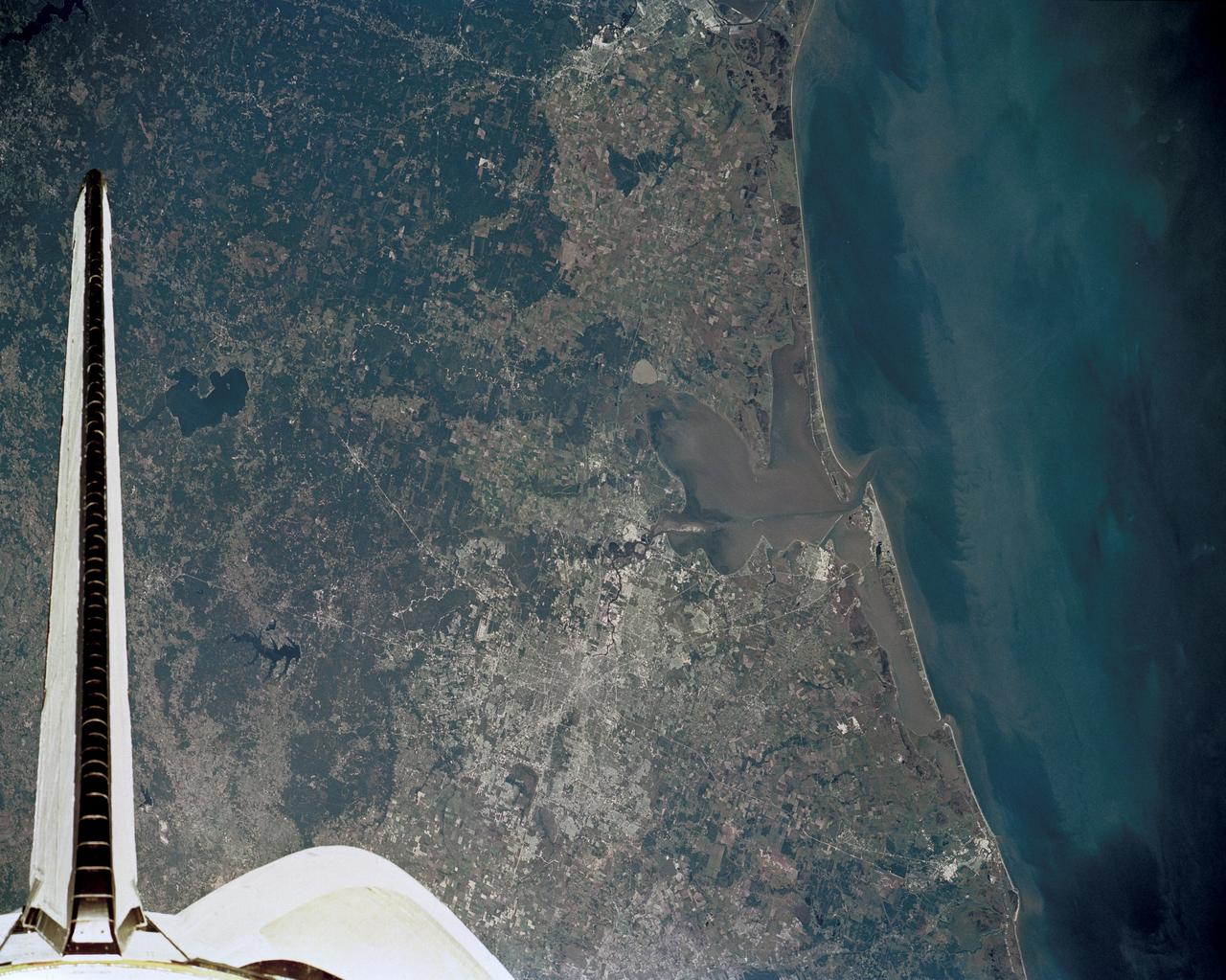
51J-143-126 (5 Oct. 1985) --- The vertical stabilizer of the Earth-orbiting Space Shuttle Atlantis serves to partially frame this scene of Metropolitan Houston. Hold photo with vertical tail at top so that north will be at top. America's fourth largest city, with its radiating highway network, lies at the junction between the East Texas piney woods, containing lakes Conroe and Livingston (near top center and top right, respectively), and the coastal prairie, now largely farmland (left side of frame). The coast stretches from the left at Freeport and the mouth of the Brazos River, past Galveston and Texas City, and the circle of the High Island Salt Dome (clearly seen at lower right near the Bolivar Peninsula), to Port Arthur on the Neches River (far right). Patterns of muddy and clear water are particularly well-displayed in Galveston and Trinity Bays, as well as in the Gulf of Mexico. With a close look, the Harris County Domed Stadium (Astrodome) can be recognized on Houston's south side. The NASA Johnson Space Center (JSC) and the Clear Lake City area are easily delineated some 25 miles southeast of downtown Houston. The scene was recorded on film by one of the STS-51J crewmembers using a handheld Hasselblad camera and 70mm film.
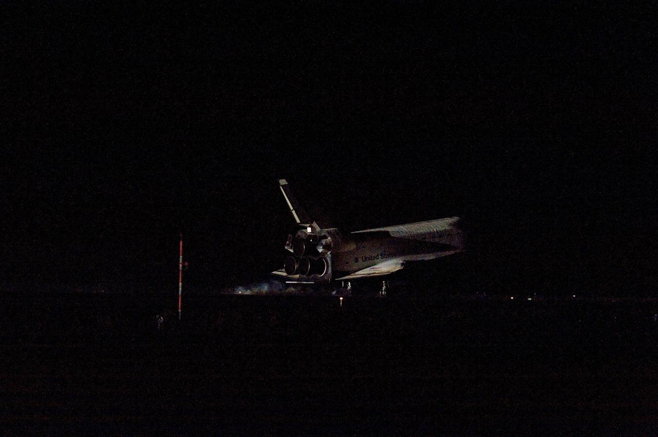
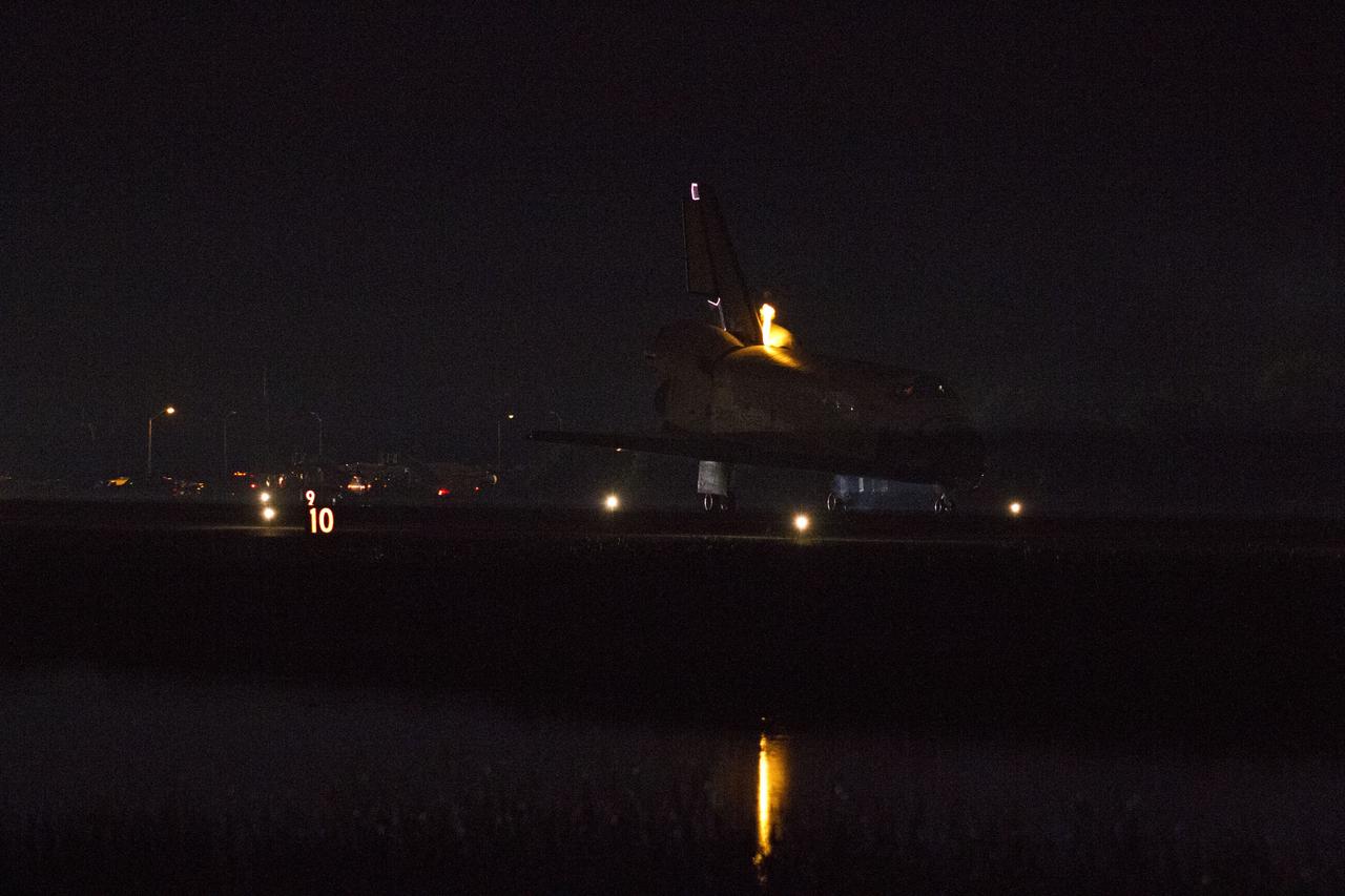
STS134-S-088 (1 June 2011) --- Space shuttle Endeavour rolls to a stop on the Shuttle Landing Facility's Runway 15 at NASA's Kennedy Space Center in Florida for the final time. Heat from the shuttle's auxiliary power units, which provide hydraulic control, can be seen at the back of Endeavour, near the vertical tail. Main gear touchdown was at 2:34:51 a.m. (EDT) on June 1, 2011, followed by nose gear touchdown at 2:35:04 a.m., and wheelstop at 2:35:36 a.m. Onboard are NASA astronauts Mark Kelly, STS-134 commander; Greg H. Johnson, pilot; Michael Fincke, Andrew Feustel, Greg Chamitoff and European Space Agency astronaut Roberto Vittori, all mission specialists. STS-134 delivered the Alpha Magnetic Spectrometer-2 (AMS) and the Express Logistics Carrier-3 (ELC-3) to the International Space Station. AMS will help researchers understand the origin of the universe and search for evidence of dark matter, strange matter and antimatter from the station. ELC-3 carried spare parts that will sustain station operations once the shuttles are retired from service. STS-134 was the 25th and final flight for Endeavour, which has spent 299 days in space, orbited Earth 4,671 times and traveled 122,883,151 miles. Photo credit: NASA
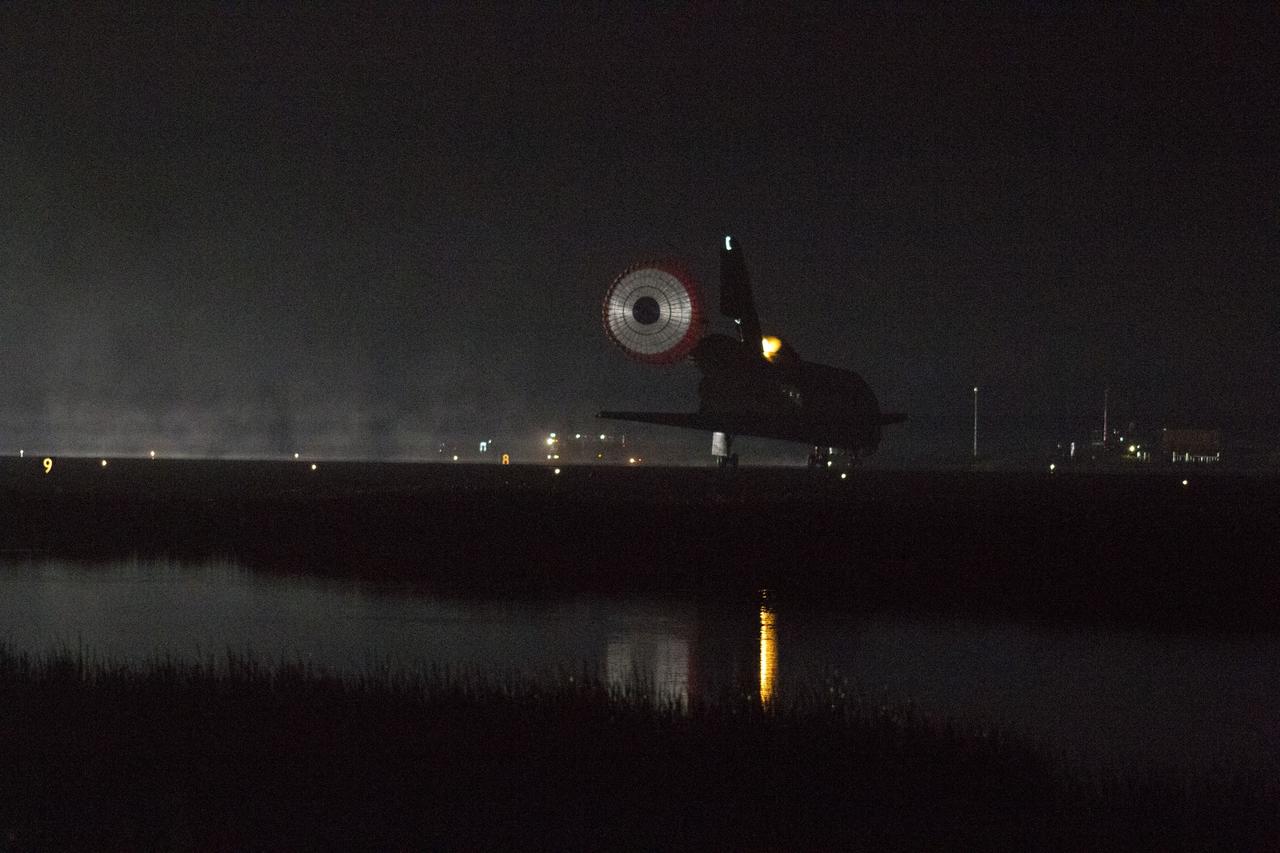
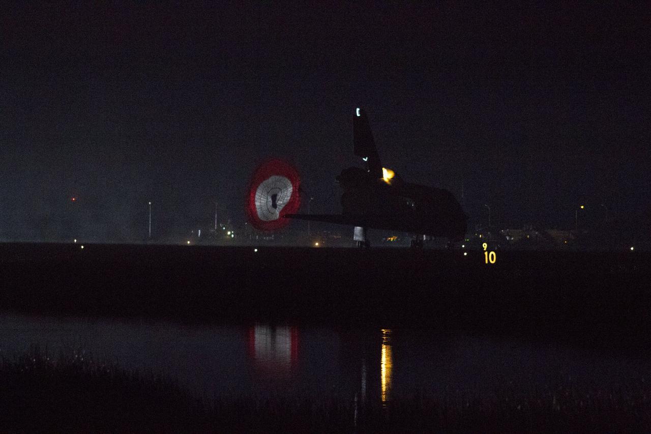
CAPE CANAVERAL, Fla. -- Xenon lights illuminate space shuttle Endeavour's unfurled drag chute as the vehicle rolls to a stop on the Shuttle Landing Facility's Runway 15 at NASA's Kennedy Space Center in Florida for the final time. Heat from the shuttle's auxiliary power units (APUs), which provide hydraulic control, can be seen at the back of Endeavour, near the vertical tail. Main gear touchdown was at 2:34:51 a.m. EDT, followed by nose gear touchdown at 2:35:04 a.m., and wheelstop at 2:35:36 a.m. On board are STS-134 Commander Mark Kelly, Pilot Greg H. Johnson, and Mission Specialists Mike Fincke, Drew Feustel, Greg Chamitoff and the European Space Agency's Roberto Vittori. STS-134 delivered the Alpha Magnetic Spectrometer-2 (AMS) and the Express Logistics Carrier-3 (ELC-3) to the International Space Station. AMS will help researchers understand the origin of the universe and search for evidence of dark matter, strange matter and antimatter from the station. ELC-3 carried spare parts that will sustain station operations once the shuttles are retired from service. STS-134 was the 25th and final flight for Endeavour, which has spent 299 days in space, orbited Earth 4,671 times and traveled 122,883,151 miles. Photo credit: NASA/Kenny Allen
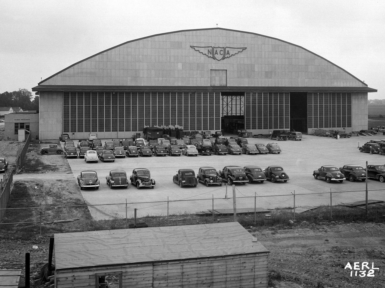
The Flight Research Building at the National Advisory Committee for Aeronautics (NACA) Aircraft Engine Research Laboratory is a 272- by 150-foot hangar with an internal height up to 90 feet. The hangar’s massive 37.5-foot-tall and 250-foot-long doors can be opened in sections to suit different size aircraft. The hangar has sheltered a diverse fleet of aircraft over the decades. These have ranged from World War II bombers to Cessna trainers and from supersonic fighter jets to a DC–9 airliner. At the time of this September 1942 photograph, however, the hangar was being used as an office building during the construction of the laboratory. In December of 1941, the Flight Research Building became the lab’s first functional building. Temporary offices were built inside the structure to house the staff while the other buildings were completed. The hangar offices were used for an entire year before being removed in early 1943. It was only then that the laboratory acquired its first aircraft, pilots and flight mechanics. The temporary one-story offices can be seen in this photograph inside the large sliding doors. Also note the vertical lift gate below the NACA logo. The gate was installed so that the tails of larger aircraft could pass into the hangar. The white Farm House that served as the Administration Building during construction can be seen in the distance to the left of the hangar.
STS134-S-074 (1 June 2011) --- Space shuttle Endeavour rolls to a stop on the Shuttle Landing Facility's Runway 15 at NASA's Kennedy Space Center in Florida for the final time. Heat from the shuttle's auxiliary power units, which provide hydraulic control, can be seen at the back of Endeavour, near the vertical tail. Main gear touchdown was at 2:34:51 a.m. (EDT) on June 1, 2011, followed by nose gear touchdown at 2:35:04 a.m., and wheelstop at 2:35:36 a.m. Onboard are NASA astronauts Mark Kelly, STS-134 commander; Greg H. Johnson, pilot; Michael Fincke, Andrew Feustel, Greg Chamitoff and European Space Agency astronaut Roberto Vittori, all mission specialists. STS-134 delivered the Alpha Magnetic Spectrometer-2 (AMS) and the Express Logistics Carrier-3 (ELC-3) to the International Space Station. AMS will help researchers understand the origin of the universe and search for evidence of dark matter, strange matter and antimatter from the station. ELC-3 carried spare parts that will sustain station operations once the shuttles are retired from service. STS-134 was the 25th and final flight for Endeavour, which has spent 299 days in space, orbited Earth 4,671 times and traveled 122,883,151 miles. Photo credit: NASA
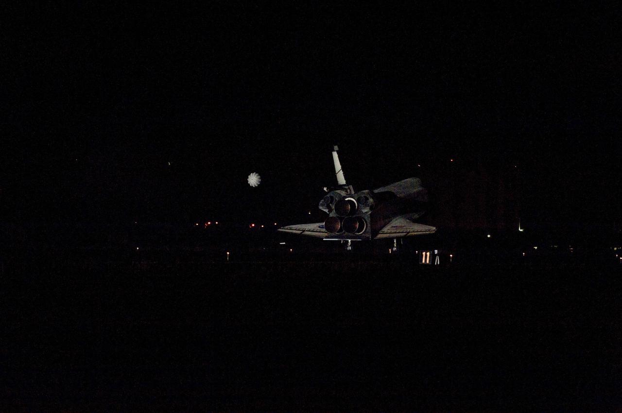
STS134-S-086 (1 June 2011) --- Space shuttle Endeavour rolls to a stop on the Shuttle Landing Facility's Runway 15 at NASA's Kennedy Space Center in Florida for the final time. Heat from the shuttle's auxiliary power units, which provide hydraulic control, can be seen at the back of Endeavour, near the vertical tail. Main gear touchdown was at 2:34:51 a.m. (EDT) on June 1, 2011, followed by nose gear touchdown at 2:35:04 a.m., and wheelstop at 2:35:36 a.m. Onboard are NASA astronauts Mark Kelly, STS-134 commander; Greg H. Johnson, pilot; Michael Fincke, Andrew Feustel, Greg Chamitoff and European Space Agency astronaut Roberto Vittori, all mission specialists. STS-134 delivered the Alpha Magnetic Spectrometer-2 (AMS) and the Express Logistics Carrier-3 (ELC-3) to the International Space Station. AMS will help researchers understand the origin of the universe and search for evidence of dark matter, strange matter and antimatter from the station. ELC-3 carried spare parts that will sustain station operations once the shuttles are retired from service. STS-134 was the 25th and final flight for Endeavour, which has spent 299 days in space, orbited Earth 4,671 times and traveled 122,883,151 miles. Photo credit: NASA
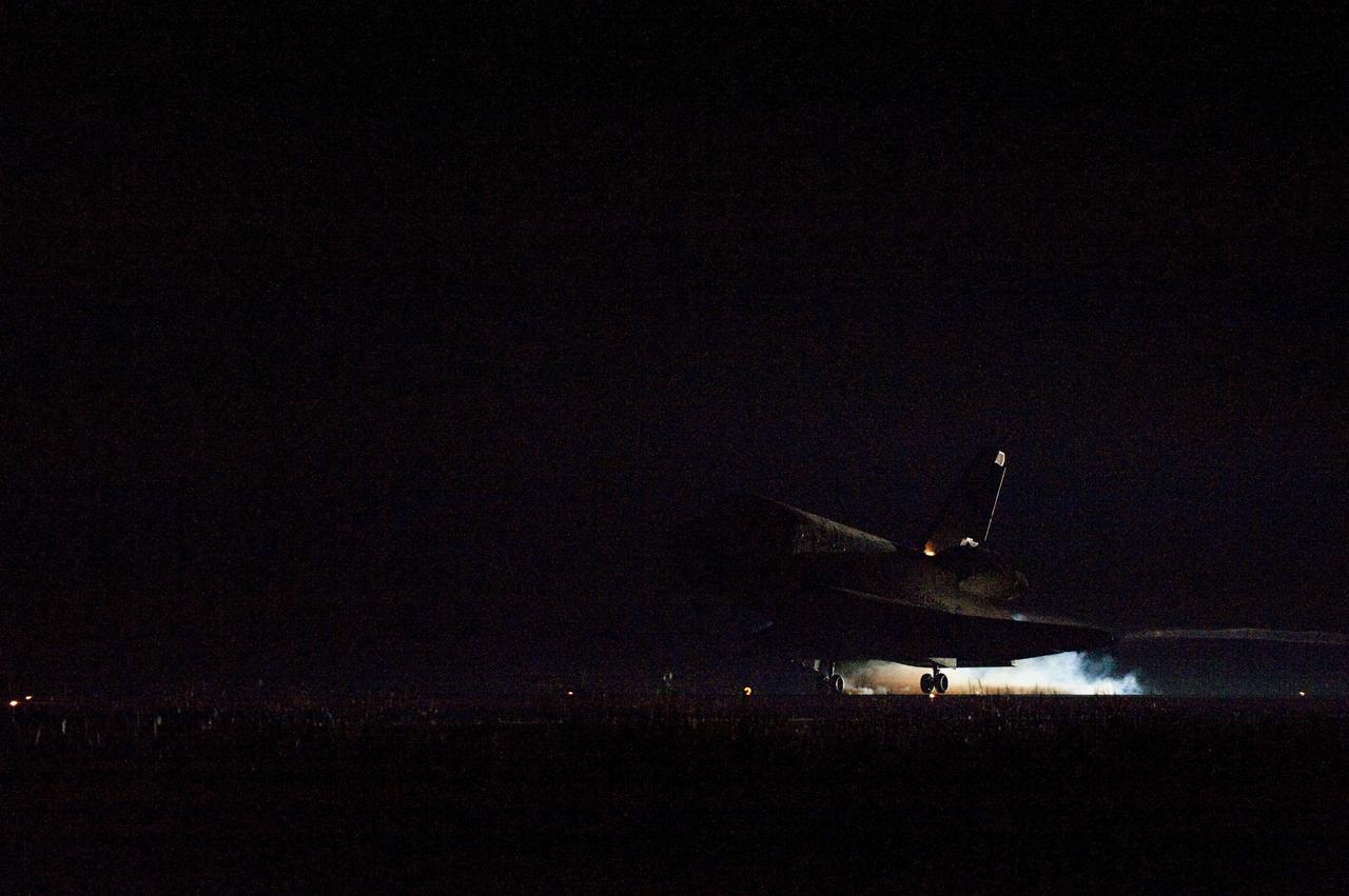
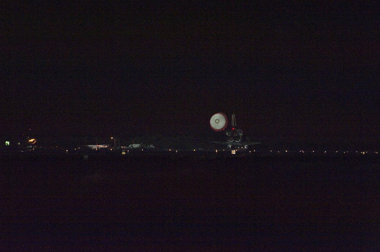
CAPE CANAVERAL, Fla. -- Heat from space shuttle Endeavour's auxiliary power units (APUs), which provide hydraulic control, can be seen at the back of the shuttle, near the vertical tail. Endeavour landed for the final time on the Shuttle Landing Facility's Runway 15 at NASA's Kennedy Space Center in Florida, marking the 25th night landing of the Space Shuttle Program. Main gear touchdown was at 2:34:51 a.m. EDT, followed by nose gear touchdown at 2:35:04 a.m., and wheelstop at 2:35:36 a.m. On board are STS-134 Commander Mark Kelly, Pilot Greg H. Johnson, and Mission Specialists Mike Fincke, Drew Feustel, Greg Chamitoff and the European Space Agency's Roberto Vittori. STS-134 delivered the Alpha Magnetic Spectrometer-2 (AMS) and the Express Logistics Carrier-3 (ELC-3) to the International Space Station. AMS will help researchers understand the origin of the universe and search for evidence of dark matter, strange matter and antimatter from the station. ELC-3 carried spare parts that will sustain station operations once the shuttles are retired from service. STS-134 was the 25th and final flight for Endeavour, which has spent 299 days in space, orbited Earth 4,671 times and traveled 122,883,151 miles. Photo credit: NASA/Tom Farrar

CAPE CANAVERAL, Fla. -- Space shuttle Endeavour rolls to a stop on the Shuttle Landing Facility's Runway 15 at NASA's Kennedy Space Center in Florida for the final time. Heat from the shuttle's auxiliary power units (APUs), which provide hydraulic control, can be seen at the back of Endeavour, near the vertical tail. Main gear touchdown was at 2:34:51 a.m. EDT, followed by nose gear touchdown at 2:35:04 a.m., and wheelstop at 2:35:36 a.m. On board are STS-134 Commander Mark Kelly, Pilot Greg H. Johnson, and Mission Specialists Mike Fincke, Drew Feustel, Greg Chamitoff and the European Space Agency's Roberto Vittori. STS-134 delivered the Alpha Magnetic Spectrometer-2 (AMS) and the Express Logistics Carrier-3 (ELC-3) to the International Space Station. AMS will help researchers understand the origin of the universe and search for evidence of dark matter, strange matter and antimatter from the station. ELC-3 carried spare parts that will sustain station operations once the shuttles are retired from service. STS-134 was the 25th and final flight for Endeavour, which has spent 299 days in space, orbited Earth 4,671 times and traveled 122,883,151 miles. Photo credit: NASA/Kenny Allen
CAPE CANAVERAL, Fla. -- Heat from space shuttle Endeavour's auxiliary power units (APUs), which provide hydraulic control, can be seen at the back of the shuttle, near the vertical tail. Endeavour landed for the final time on the Shuttle Landing Facility's Runway 15 at NASA's Kennedy Space Center in Florida, marking the 25th night landing of the Space Shuttle Program. Main gear touchdown was at 2:34:51 a.m. EDT, followed by nose gear touchdown at 2:35:04 a.m., and wheelstop at 2:35:36 a.m. On board are STS-134 Commander Mark Kelly, Pilot Greg H. Johnson, and Mission Specialists Mike Fincke, Drew Feustel, Greg Chamitoff and the European Space Agency's Roberto Vittori. STS-134 delivered the Alpha Magnetic Spectrometer-2 (AMS) and the Express Logistics Carrier-3 (ELC-3) to the International Space Station. AMS will help researchers understand the origin of the universe and search for evidence of dark matter, strange matter and antimatter from the station. ELC-3 carried spare parts that will sustain station operations once the shuttles are retired from service. STS-134 was the 25th and final flight for Endeavour, which has spent 299 days in space, orbited Earth 4,671 times and traveled 122,883,151 miles. Photo credit: NASA/Kenny Allen
STS134-S-085 (1 June 2011) --- Space shuttle Endeavour rolls to a stop on the Shuttle Landing Facility's Runway 15 at NASA's Kennedy Space Center in Florida for the final time. Heat from the shuttle's auxiliary power units, which provide hydraulic control, can be seen at the back of Endeavour, near the vertical tail. Main gear touchdown was at 2:34:51 a.m. (EDT) on June 1, 2011, followed by nose gear touchdown at 2:35:04 a.m., and wheelstop at 2:35:36 a.m. Onboard are NASA astronauts Mark Kelly, STS-134 commander; Greg H. Johnson, pilot; Michael Fincke, Andrew Feustel, Greg Chamitoff and European Space Agency astronaut Roberto Vittori, all mission specialists. STS-134 delivered the Alpha Magnetic Spectrometer-2 (AMS) and the Express Logistics Carrier-3 (ELC-3) to the International Space Station. AMS will help researchers understand the origin of the universe and search for evidence of dark matter, strange matter and antimatter from the station. ELC-3 carried spare parts that will sustain station operations once the shuttles are retired from service. STS-134 was the 25th and final flight for Endeavour, which has spent 299 days in space, orbited Earth 4,671 times and traveled 122,883,151 miles. Photo credit: NASA
CAPE CANAVERAL, Fla. -- Heat from space shuttle Endeavour's auxiliary power units (APUs), which provide hydraulic control, can be seen at the back of the shuttle, near the vertical tail. Endeavour landed for the final time on the Shuttle Landing Facility's Runway 15 at NASA's Kennedy Space Center in Florida, marking the 25th night landing of the Space Shuttle Program. Main gear touchdown was at 2:34:51 a.m. EDT, followed by nose gear touchdown at 2:35:04 a.m., and wheelstop at 2:35:36 a.m. On board are STS-134 Commander Mark Kelly, Pilot Greg H. Johnson, and Mission Specialists Mike Fincke, Drew Feustel, Greg Chamitoff and the European Space Agency's Roberto Vittori. STS-134 delivered the Alpha Magnetic Spectrometer-2 (AMS) and the Express Logistics Carrier-3 (ELC-3) to the International Space Station. AMS will help researchers understand the origin of the universe and search for evidence of dark matter, strange matter and antimatter from the station. ELC-3 carried spare parts that will sustain station operations once the shuttles are retired from service. STS-134 was the 25th and final flight for Endeavour, which has spent 299 days in space, orbited Earth 4,671 times and traveled 122,883,151 miles. Photo credit: NASA/Kenny Allen

This radar image of Salt Lake City, Utah, illustrates the different land use patterns that are present in the Utah Valley. Salt Lake City lies between the shores of the Great Salt Lake (the dark area on the left side of the image) and the Wasatch Front Range (the mountains in the upper half of the image). The Salt Lake City area is of great interest to urban planners because of the combination of lake, valley and alpine environments that coexist in the region. Much of the southern shore of the Great Salt Lake is a waterfowl management area. The green grid pattern in the right center of the image is Salt Lake City and its surrounding communities. The Salt Lake City airport is visible as the brown rectangle near the center of the image. Interstate Highway 15 runs from the middle right edge to the upper left of the image. The bright white patch east of Interstate 15 is the downtown area, including Temple Square and the state capitol. The University of Utah campus is the yellowish area that lies at the base of the mountains, east of Temple Square. The large reservoir in the lower left center is a mine tailings pond. The semi-circular feature in the mountains at the bottom edge of the image is the Kennecott Copper Mine. The area shown is 60 kilometers by 40 kilometers (37 miles by 25 miles) and is centered at 40.6 degrees north latitude, 112.0 degrees west longitude. North is toward the upper left. This image was acquired by the Spaceborne Imaging Radar-C/X-Band Synthetic Aperture Radar (SIR-C/X-SAR) aboard the space shuttle Endeavour on April 10, 1994. The colors in this image represent the following radar channels and polarizations: red is L-band, horizontally transmitted and received; green is L-band, horizontally transmitted and vertically received; and blue is C-band, horizontally transmitted and vertically received. SIR-C/X-SAR, a joint mission of the German, Italian and United States space agencies, is part of NASA's Mission to Planet Earth program. http://photojournal.jpl.nasa.gov/catalog/PIA01798
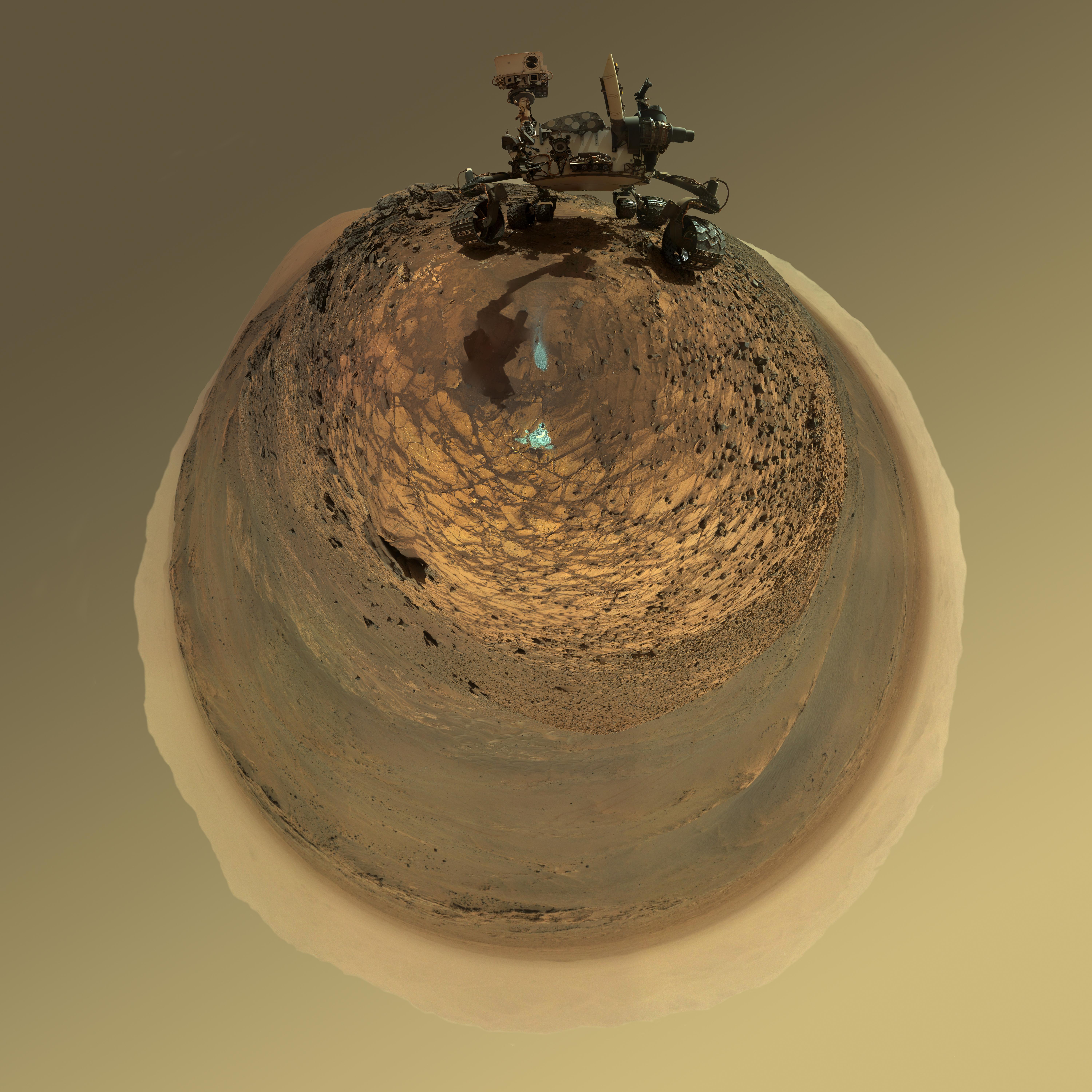
This version of a self-portrait of NASA's Curiosity Mars rover at a drilling site called "Buckskin" on lower Mount Sharp is presented as a stereographic projection, which shows the horizon as a circle. It is a mosaic assembled from the same set of 92 component raw images used for the flatter-horizon version at PIA19807. The component images were taken by Curiosity's Mars Hand Lens Imager (MAHLI) on Aug. 5, 2015, during the 1,065th Martian day, or sol, of the rover's work on Mars. Curiosity drilled the hole at Buckskin during Sol 1060 (July 30, 2015). Two patches of pale, powdered rock material pulled from inside Buckskin are visible in this scene, in front of the rover. The patch closer to the rover is where the sample-handling mechanism on Curiosity's robotic arm dumped collected material that did not pass through a sieve in the mechanism. Sieved sample material was delivered to laboratory instruments inside the rover. The patch farther in front of the rover, roughly triangular in shape, shows where fresh tailings spread downhill from the drilling process. The drilled hole, 0.63 inch (1.6 centimeters) in diameter, is at the upper point of the tailings. The rover is facing northeast, looking out over the plains from the crest of a 20-foot (6-meter) hill that it climbed to reach the "Marias Pass" area. The upper levels of Mount Sharp are visible behind the rover, while Gale Crater's northern rim dominates most of the rest of the horizon.the horizon on the left and right of the mosaic. MAHLI is mounted at the end of the rover's robotic arm. For this self-portrait, the rover team positioned the camera lower in relation to the rover body than for any previous full self-portrait of Curiosity. The assembled mosaic does not include the rover's arm beyond a portion of the upper arm held nearly vertical from the shoulder joint. Shadows from the rest of the arm and the turret of tools at the end of the arm are visible on the ground. With the wrist motions and turret rotations used in pointing the camera for the component images, the arm was positioned out of the shot in the frames or portions of frames used in this mosaic. MAHLI was built by Malin Space Science Systems, San Diego. NASA's Jet Propulsion Laboratory, a division of the California Institute of Technology in Pasadena, manages the Mars Science Laboratory Project for the NASA Science Mission Directorate, Washington. JPL designed and built the project's Curiosity rover. http://photojournal.jpl.nasa.gov/catalog/PIA19806
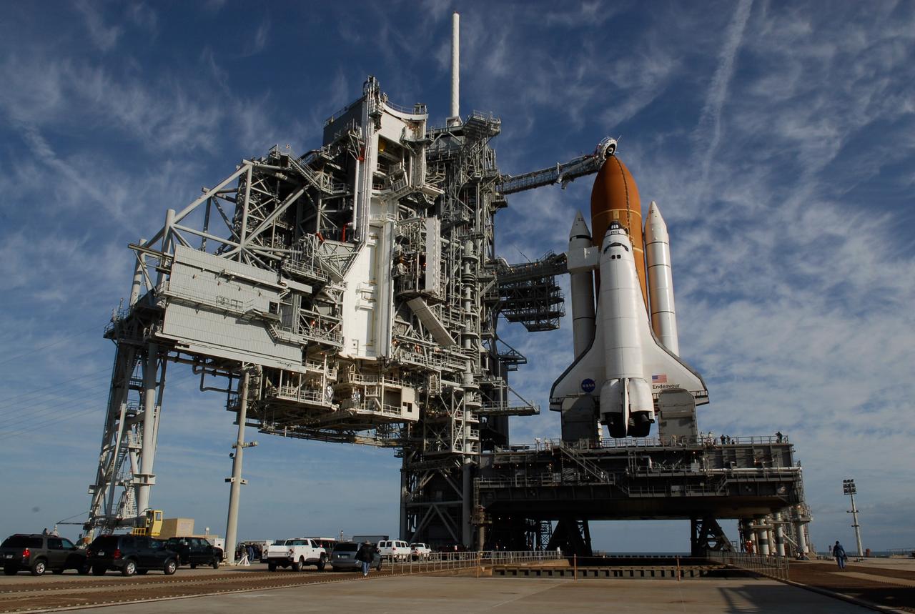
KENNEDY SPACE CENTER, FLA. -- On Launch Pad 39A at NASA's Kennedy Space Center, rollback of the rotating service structure (at left) reveals space shuttle Endeavour atop the mobile launcher platform. First motion was at 8:23 a.m. and rollback was complete at 8:55 a.m. Above the orange external tank is seen the "beanie cap" at the end of the gaseous oxygen vent arm, extending from the fixed service structure. Vapors are created as the liquid oxygen in the external tank boil off. The hood vents the gaseous oxygen vapors away from the space shuttle vehicle. Below is the orbiter access arm with the White Room at the end, flush against the shuttle. The crew gains access into the orbiter through the White Room. On either side of the main engines and below the wings are the tail service masts, which provide several umbilical connections to the orbiter, including a liquid-oxygen line through one and a liquid-hydrogen line through another. The rotating structure provides protected access to the orbiter for changeout and servicing of payloads at the pad. The structure is supported by a rotating bridge that pivots about a vertical axis on the west side of the pad's flame trench. After the RSS is rolled back, the orbiter is ready for fuel cell activation and external tank cryogenic propellant loading operations. The pad is cleared to the perimeter gate for operations to fill the external tank with about 500,000 gallons of cryogenic propellants used by the shuttle’s main engines. This is done at the pad approximately eight hours before the scheduled launch. Endeavour and its crew will deliver the first section of the Japan Aerospace Exploration Agency's Kibo laboratory and the Canadian Space Agency's two-armed robotic system, Dextre. Launch is scheduled for 2:28 a.m. EDT March 11. Photo credit: NASA/Kim Shiflett
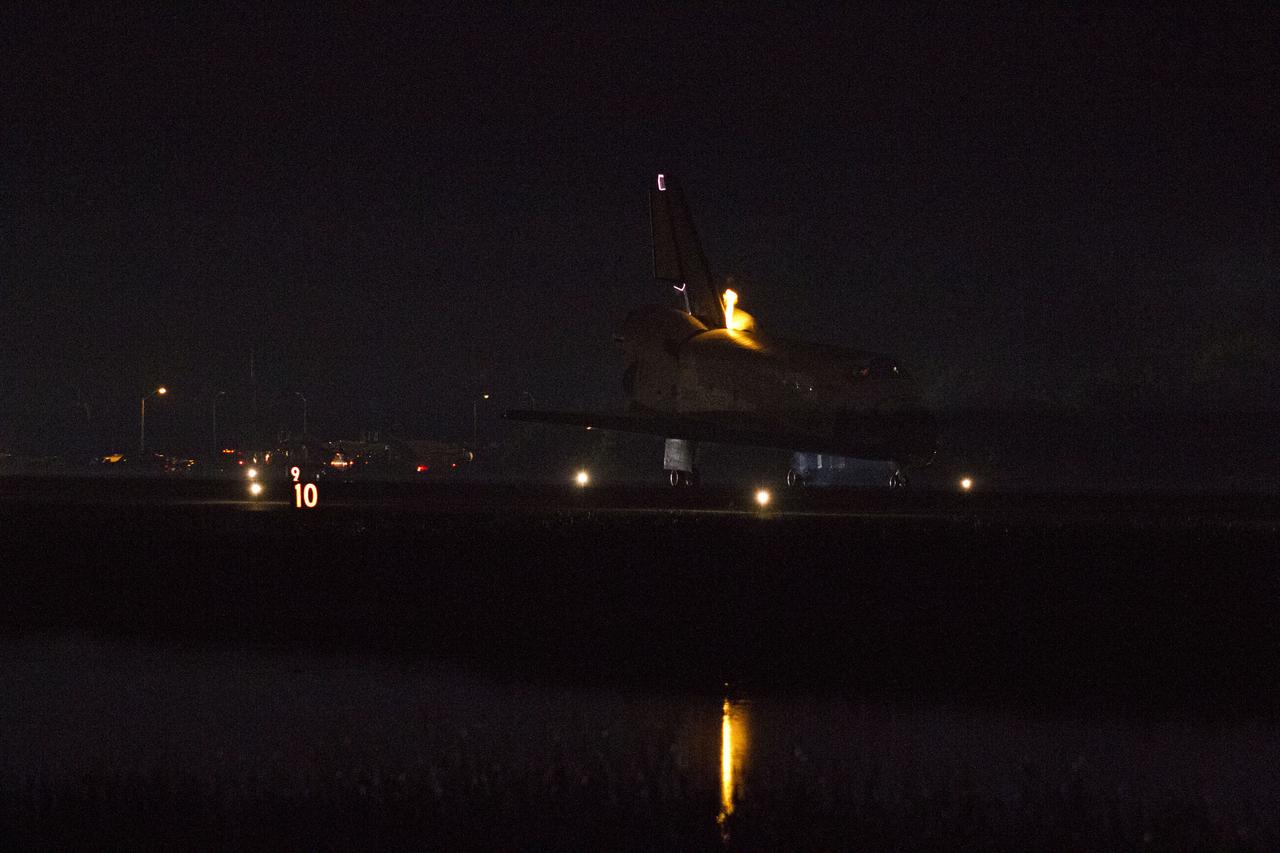
STS134-S-076 (1 June 2011) --- Heat from space shuttle Endeavour's auxiliary power units, which provide hydraulic control, can be seen at the back of the shuttle, near the vertical tail. Endeavour landed for the final time on the Shuttle Landing Facility's Runway 15 at NASA's Kennedy Space Center in Florida, marking the 24th night landing of the Space Shuttle Program. Main gear touchdown was at 2:34:51 a.m. (EDT) on June 1, 2011, followed by nose gear touchdown at 2:35:04 a.m., and wheelstop at 2:35:36 a.m. Onboard are NASA astronauts Mark Kelly, STS-134 commander; Greg H. Johnson, pilot; Michael Fincke, Andrew Feustel, Greg Chamitoff and European Space Agency astronaut Roberto Vittori, all mission specialists. STS-134 delivered the Alpha Magnetic Spectrometer-2 (AMS) and the Express Logistics Carrier-3 (ELC-3) to the International Space Station. AMS will help researchers understand the origin of the universe and search for evidence of dark matter, strange matter and antimatter from the station. ELC-3 carried spare parts that will sustain station operations once the shuttles are retired from service. STS-134 was the 25th and final flight for Endeavour, which has spent 299 days in space, orbited Earth 4,671 times and traveled 122,883,151 miles. Photo credit: NASA
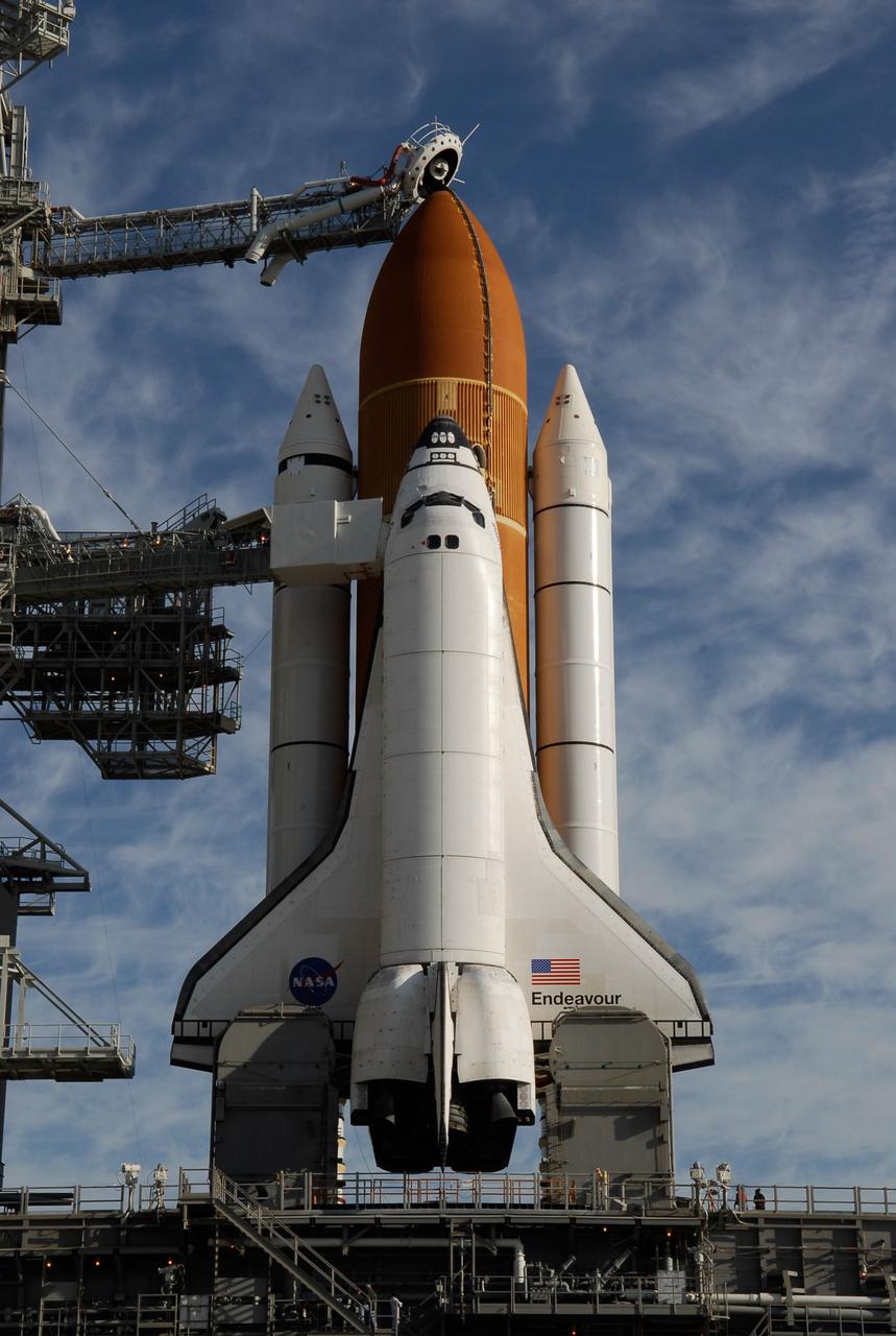
KENNEDY SPACE CENTER, FLA. -- On Launch Pad 39A at NASA's Kennedy Space Center, rollback of the rotating service structure reveals space shuttle Endeavour atop the mobile launcher platform. First motion was at 8:23 a.m. and rollback was complete at 8:55 a.m. Above the orange external tank is seen the "beanie cap" at the end of the gaseous oxygen vent arm, extending from the fixed service structure. Vapors are created as the liquid oxygen in the external tank boil off. The hood vents the gaseous oxygen vapors away from the space shuttle vehicle. Below is the orbiter access arm with the White Room at the end, flush against the shuttle. The crew gains access into the orbiter through the White Room. On either side of the main engines and below the wings are the tail service masts, which provide several umbilical connections to the orbiter, including a liquid-oxygen line through one and a liquid-hydrogen line through another. The rotating structure provides protected access to the orbiter for changeout and servicing of payloads at the pad. The structure is supported by a rotating bridge that pivots about a vertical axis on the west side of the pad's flame trench. After the RSS is rolled back, the orbiter is ready for fuel cell activation and external tank cryogenic propellant loading operations. The pad is cleared to the perimeter gate for operations to fill the external tank with about 500,000 gallons of cryogenic propellants used by the shuttle’s main engines. This is done at the pad approximately eight hours before the scheduled launch. Endeavour and its crew will deliver the first section of the Japan Aerospace Exploration Agency's Kibo laboratory and the Canadian Space Agency's two-armed robotic system, Dextre. Launch is scheduled for 2:28 a.m. EDT March 11. Photo credit: NASA/Kim Shiflett
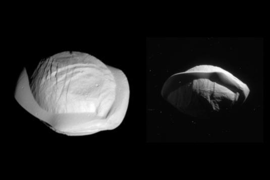
These two images from NASA's Cassini spacecraft show how the spacecraft's perspective changed as it passed within 15,300 miles (24,600 kilometers) of Saturn's moon Pan on March 7, 2017. This was Cassini's closest-ever encounter with Pan, improving the level of detail seen on the little moon by a factor of eight over previous observations. The views show the northern and southern hemispheres of Pan, at left and right, respectively. Both views look toward Pan's trailing side, which is the side opposite the moon's direction of motion as it orbits Saturn. Cassini imaging scientists think that Pan formed within Saturn's rings, with ring material accreting onto it and forming the rounded shape of its central mass, when the outer part of the ring system was quite young and the ring system was vertically thicker. Thus, Pan probably has a core of icy material that is denser than the softer mantle around it. The distinctive, thin ridge around Pan's equator is thought to have come after the moon formed and had cleared the gap in the rings in which it resides today. At that point the ring was as thin as it is today, yet there was still ring material accreting onto Pan. However, at the tail end of the process, that material was raining down on the moon solely in (or close to) its equatorial region. Thus, the infalling material formed a tall, narrow ridge of material. On a larger, more massive body, this ridge would not be so tall (relative to the body) because gravity would cause it to flatten out. But Pan's gravity is so feeble that the ring material simply settles onto Pan and builds up. Other dynamical forces keep the ridge from growing indefinitely. The images are presented here at their original size. The views were acquired by the Cassini narrow-angle camera at distances of 15,275 miles or 24,583 kilometers (left view) and 23,199 miles or 37,335 kilometers (right view). Image scale is 482 feet or 147 meters per pixel (left view) and about 735 feet or 224 meters per pixel (right view). http://photojournal.jpl.nasa.gov/catalog/PIA21436