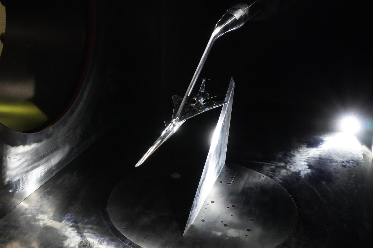
Here you see the X-59 scaled model inside the JAXA supersonic wind tunnel during critical tests related to sound predictions.
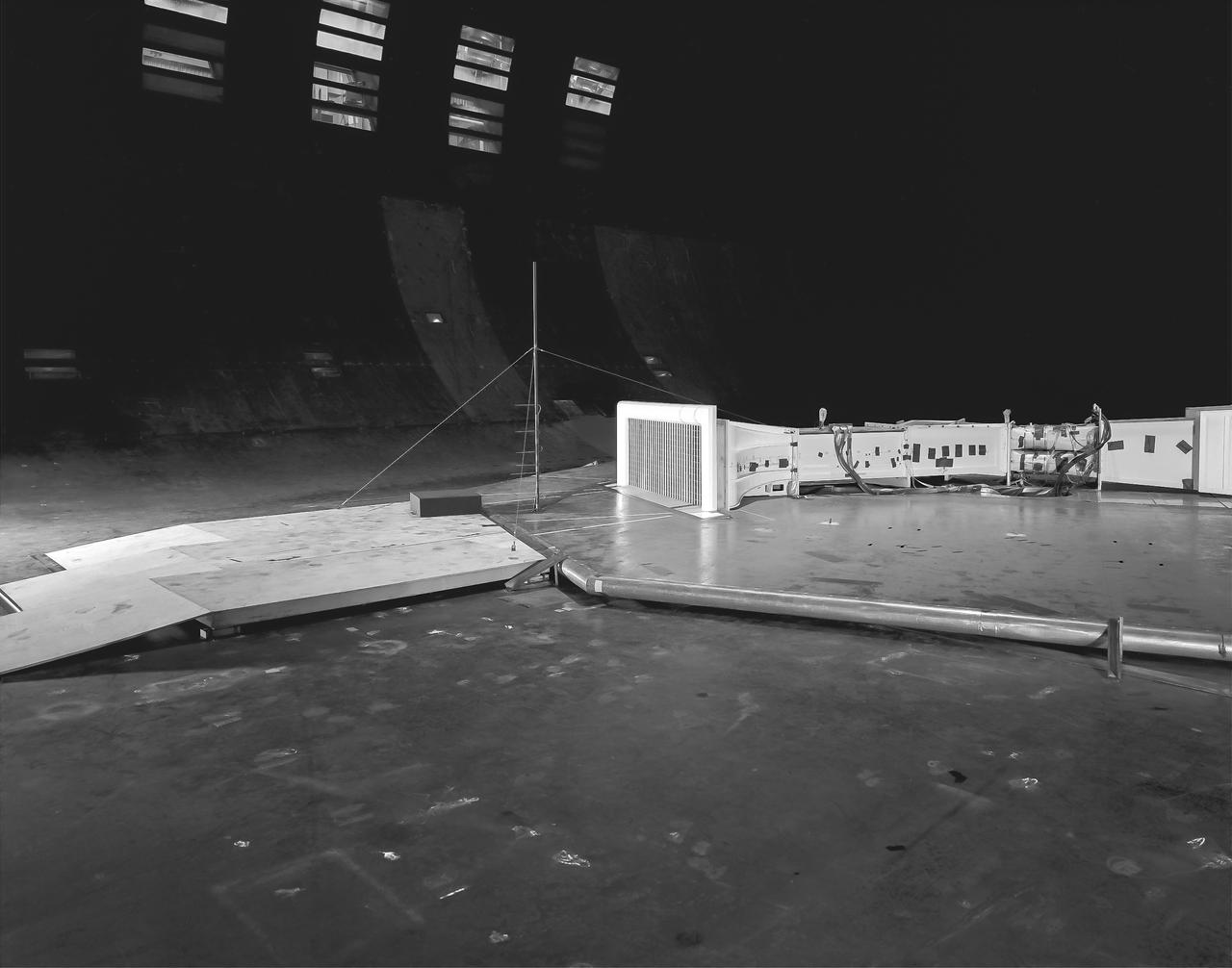
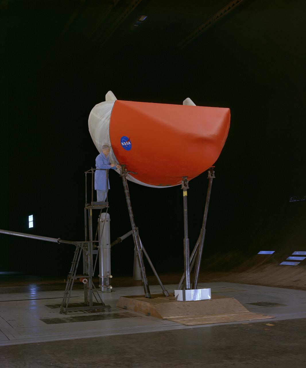
(03/12/1976) 1/50 scale model of the 80x120 foot wind tunnel model (NFAC) in the test section of the 40x80 wind tunnel. Model viewed from the west, mounted on a rotating ground board designed for this test. Ramp leading to ground board includes a generic building placed in front of the 80x120 inlet.
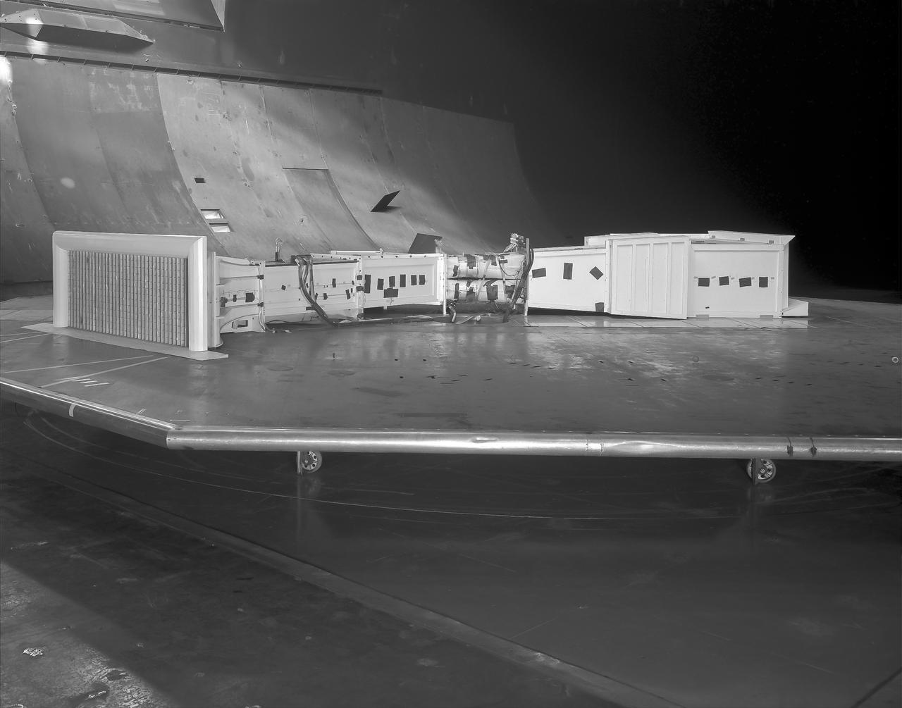
(03/12/1976) 1/50 scale model of the 80x120 foot wind tunnel model (NFAC) in the test section of the 40x80 foot wind tunnel. Model mounted on a rotating ground board designed for this test, viewed from the west, oriented for North wind.
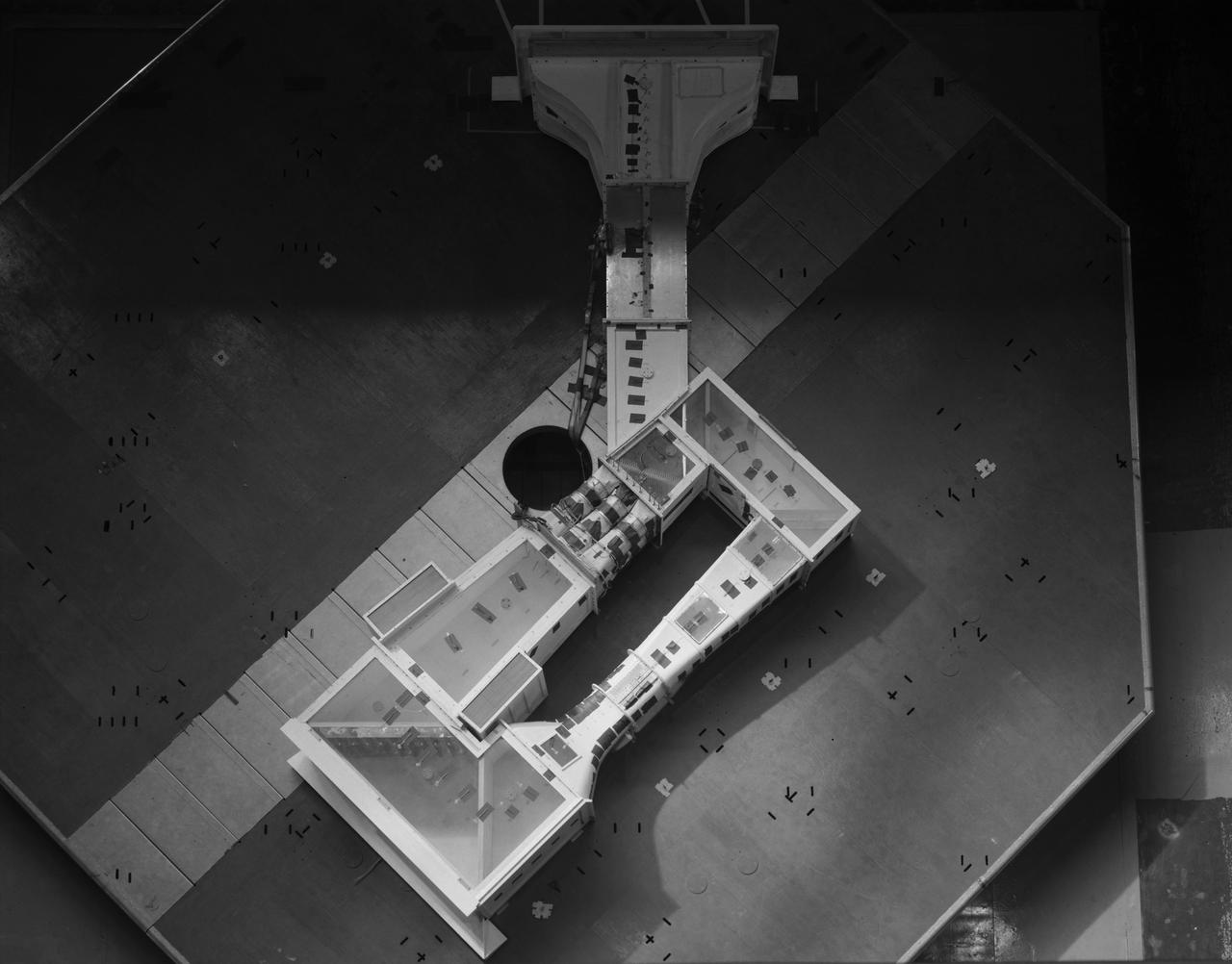
(03/12/1976) Overhead view of 1/50 scale model of the 80x120 foot wind tunnel model (NFAC) in the test section of the 40x80 wind tunnel at NASA Ames. Model mounted on a rotating ground board designed for this test.
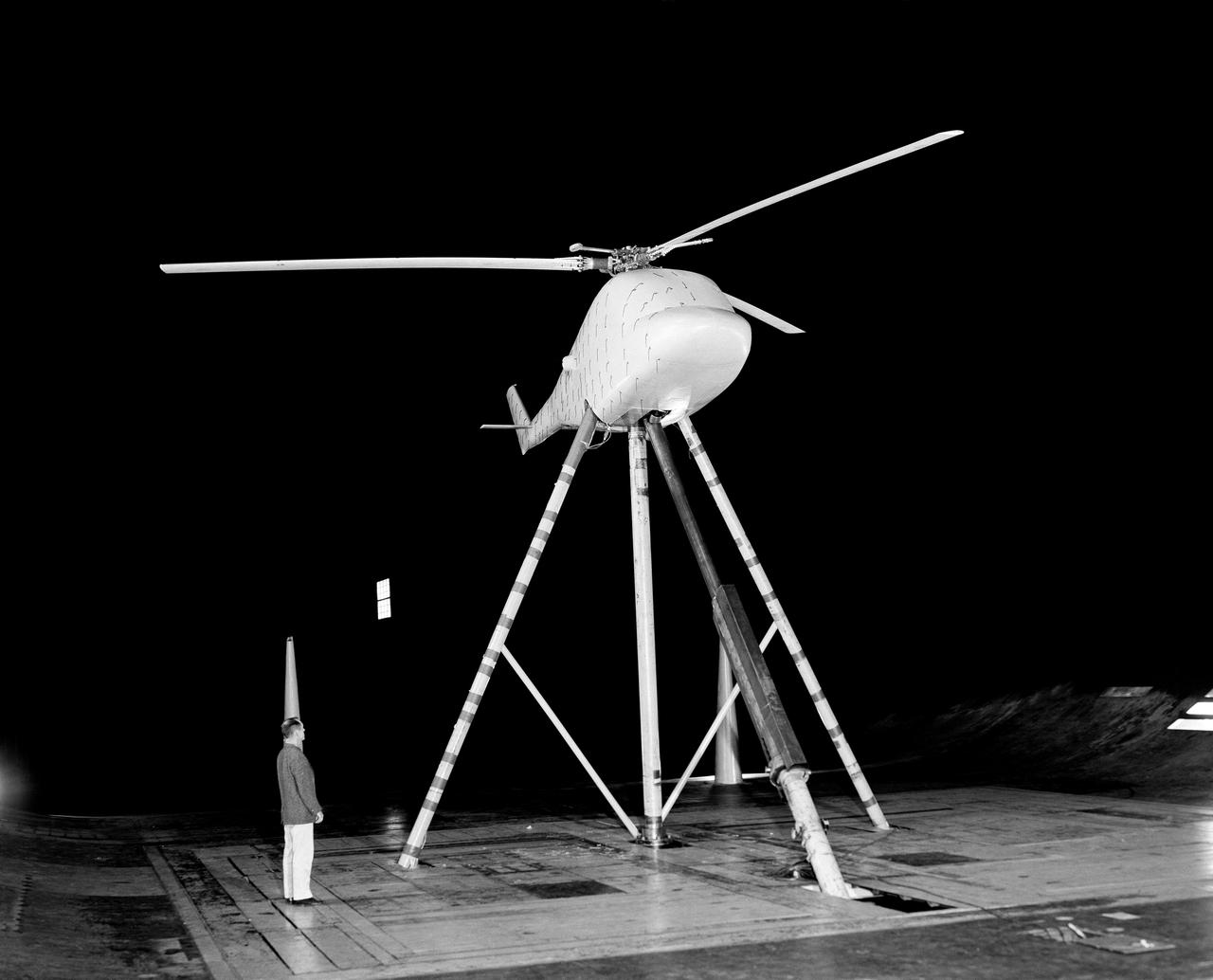
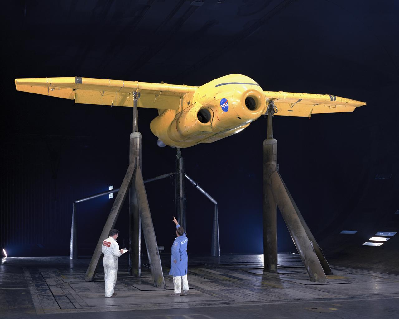
3/4 front view of Lockheed Rigid Rotor model in Ames 40x80 foot wind Tunnel.
3/4 front view from below of Delta wing Model with Nose Inlet in Ames 40x80 foot wind tunnel.
A chambered and twisted wing-body. Arrow wing hypersonic model tested in the 6x6 foot wind tunnel at the NASA Ames Research Center.
AGARD-B WIND TUNNEL MODEL, VIEW 1 OF 3
AGARD-B WIND TUNNEL MODEL, VIEW 1 OF 3
AGARD-B WIND TUNNEL MODEL, VIEW 1 OF 3
Deep Stall Model in Ames 40x80 foot Wind Tunnel. 3/4 front view from below of swept wing jet transport with T-Tail and Aft Engins, with Art Morris.
3/4 rear view from below of swept wing jet transport with T-Tail and Aft Engins, with Art Morris. Deep Stall Model in Ames 40x80 foot Wind Tunnel.
Forward overhead view of lift fan transport model, with two, of a possible six, high pressure ratio wing lift fans. Lift Fan Model In 40 X 80 Wind Tunnel; Test 40-347
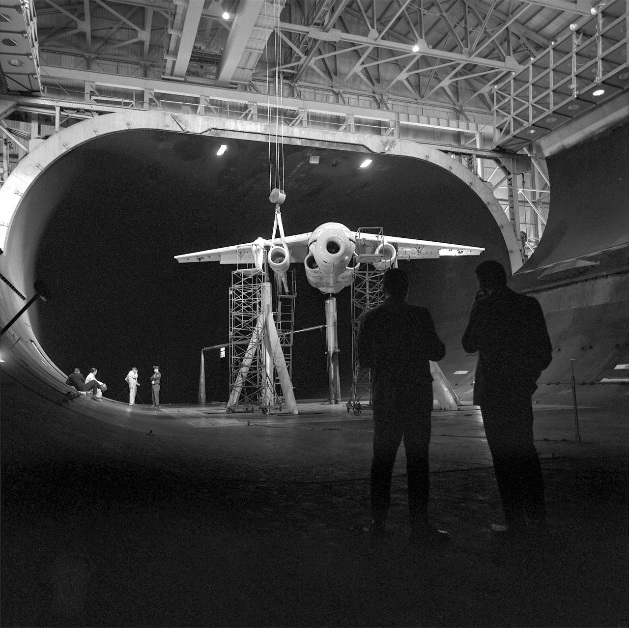
Supersonic transport model test in 40x80 foot wind tunnel, 3/4 overhead view of model in shop floor. 04/06/1961 R 975 T
3/4 view of model in cruise configuration with 25 deg. Sweep, AR=6.9. SCAT-16; Variable Sweep Model in 40x80 Wind Tunnel at NASA Ames.

Overhead, front view of Large-Scale Upper-Surface Blowing Model using JT15D Engines. Test #441
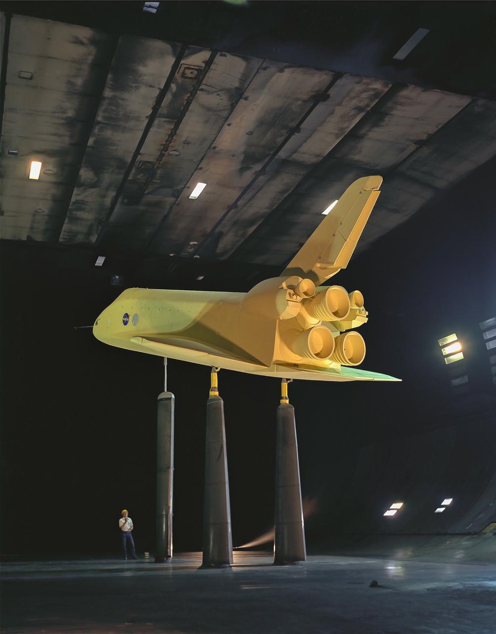
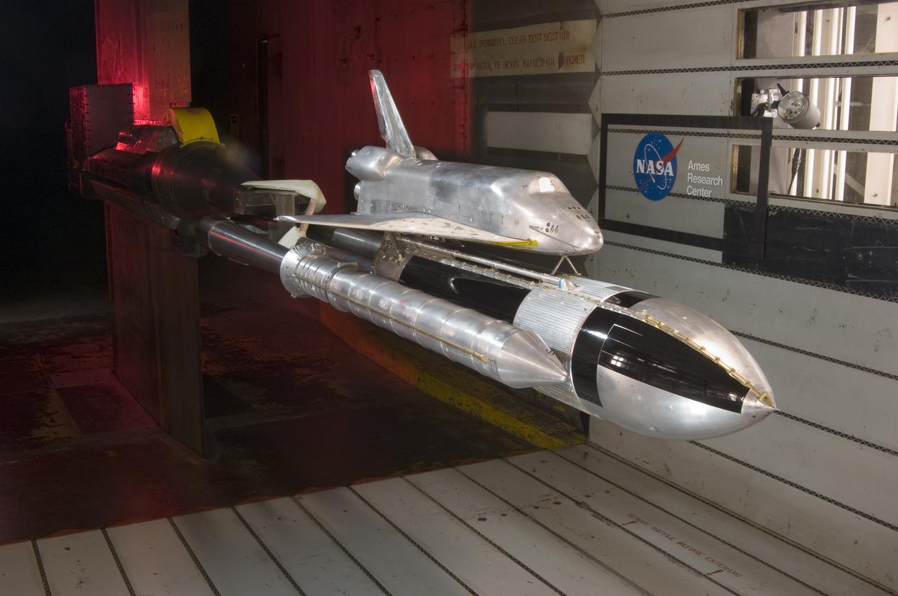
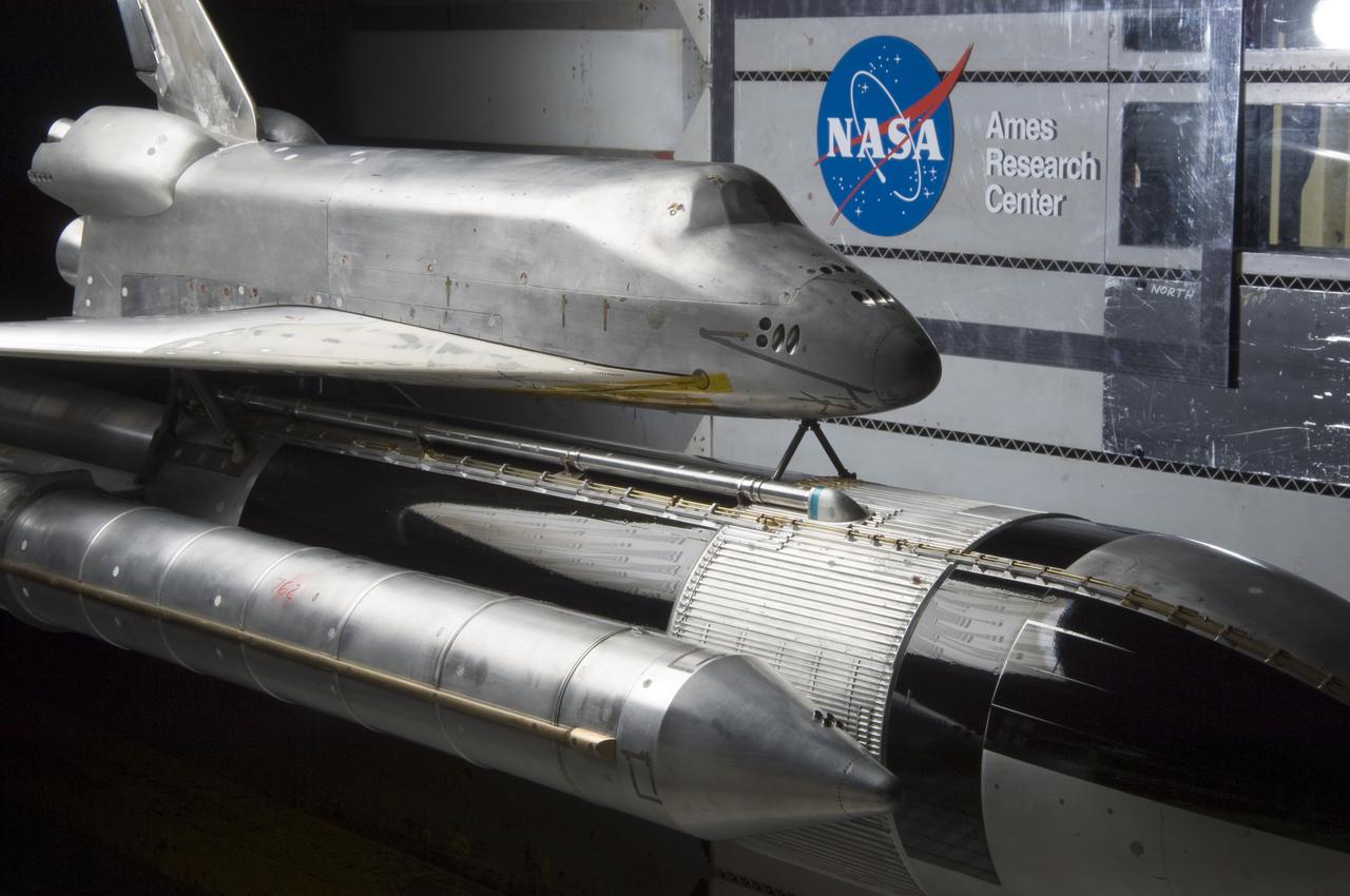
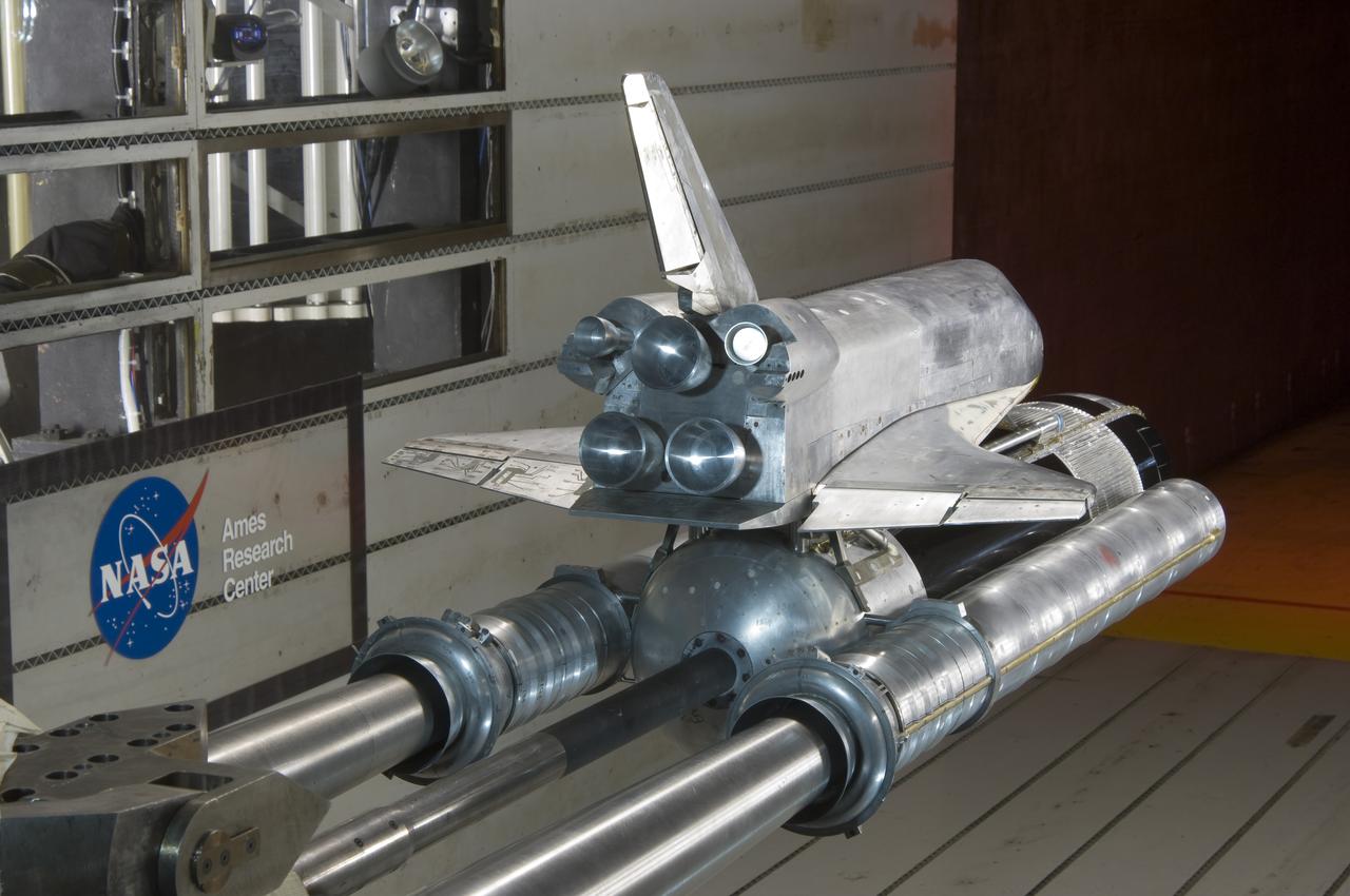
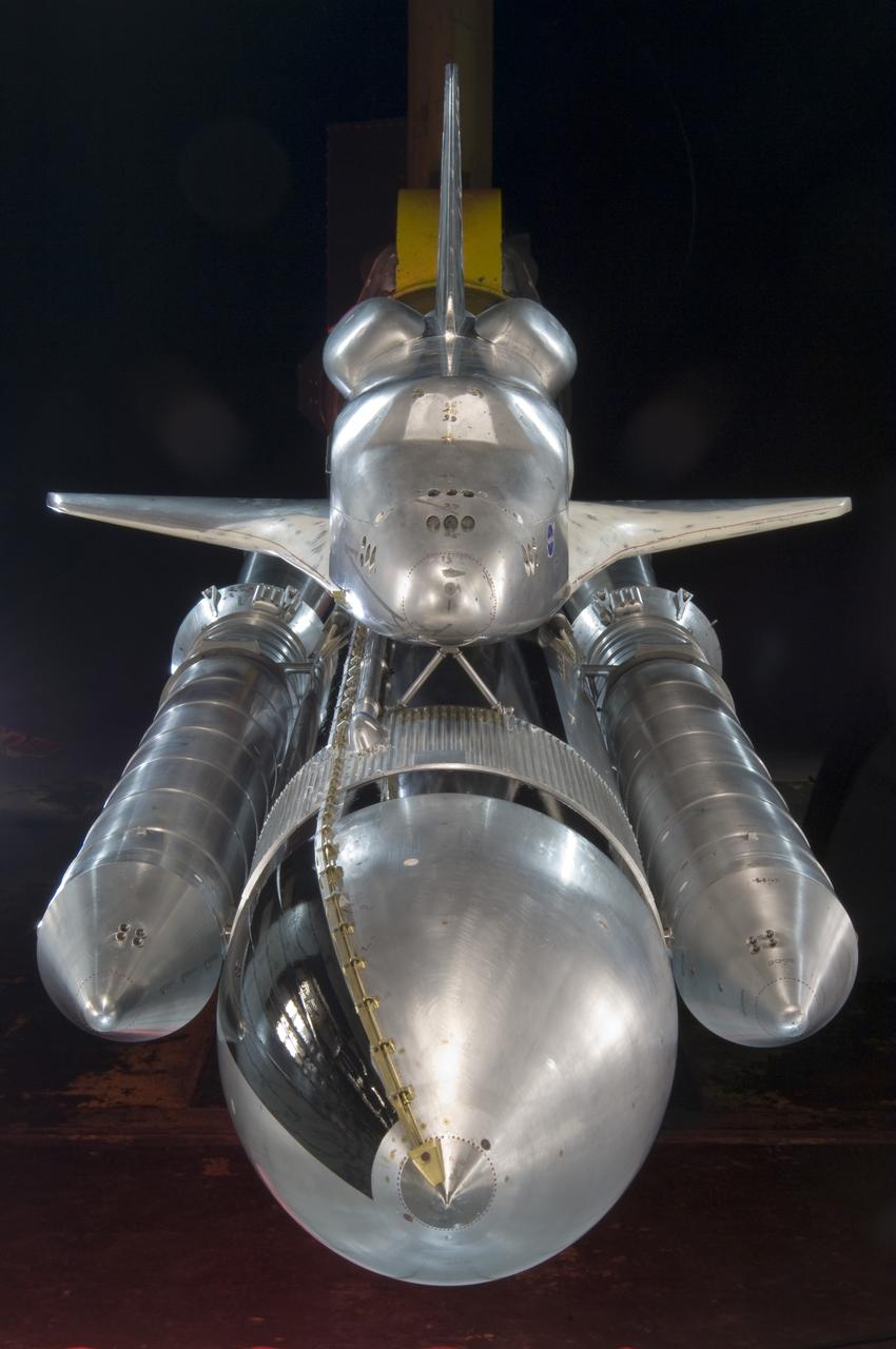
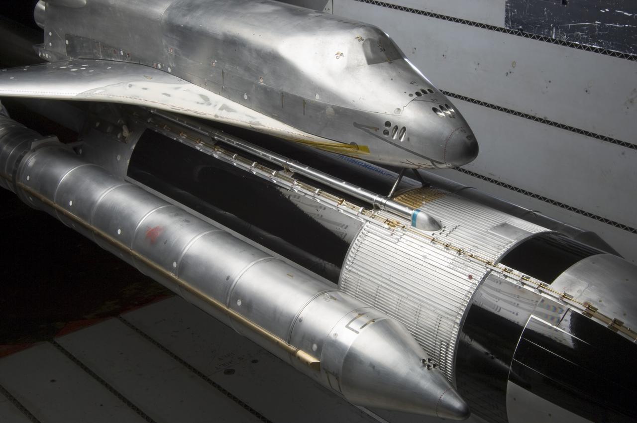
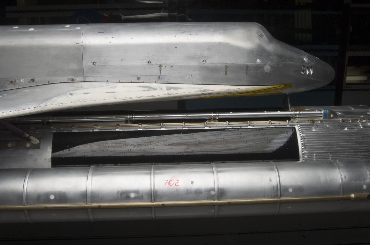
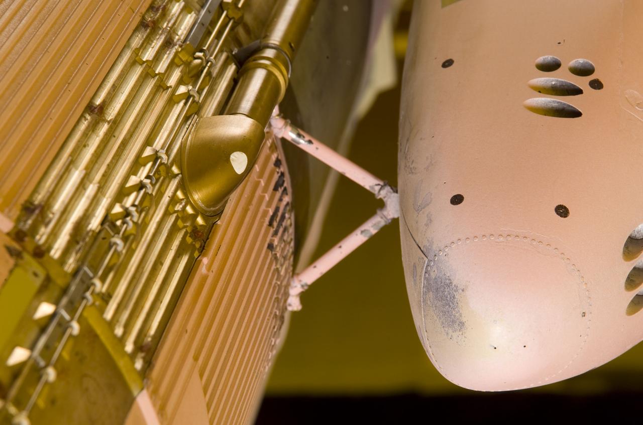
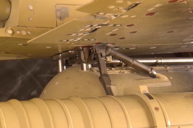
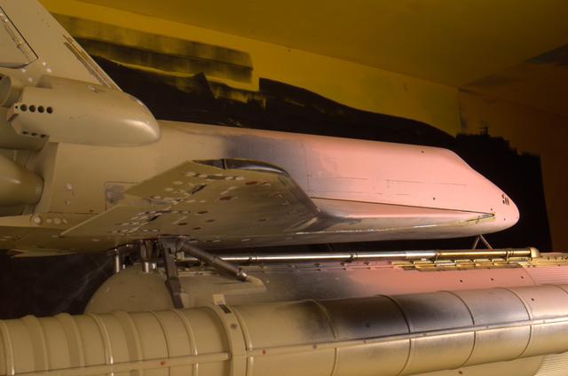
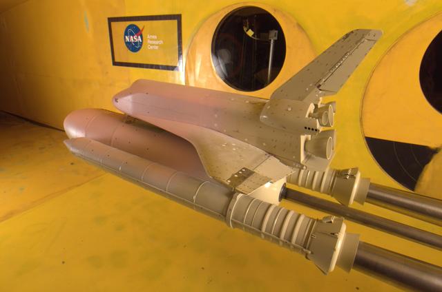
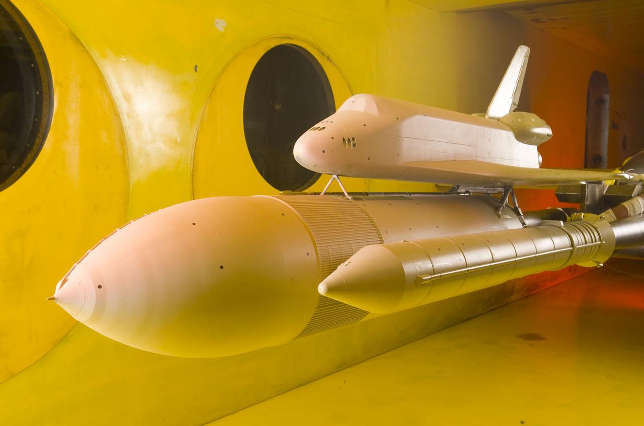
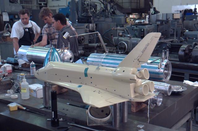
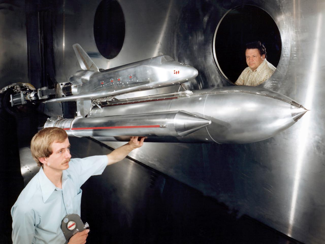
Space Shuttle SSV Orbiter Model A100 0.36 Scale In 40x80 Foot Wind Tunnel. 3/4 lower rear view.
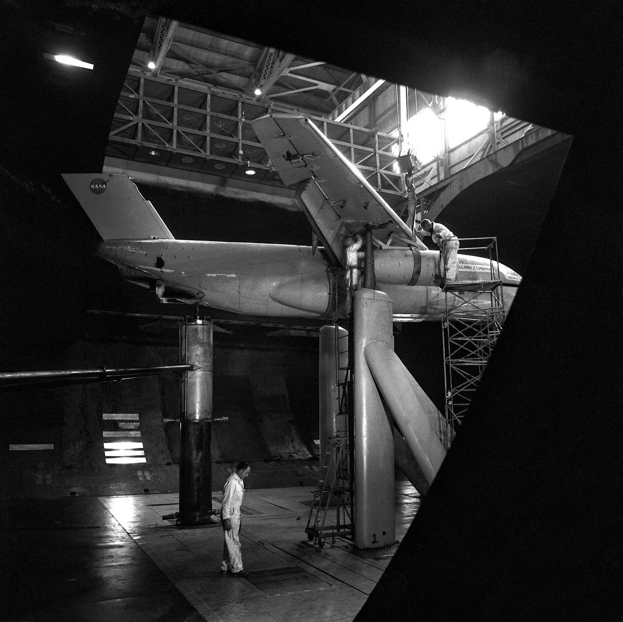
de Havilland augmenter wing model 3/4 front view in 40 x 80 wind tunnel. JOHN CONWAY, ALAN WHEELBAND
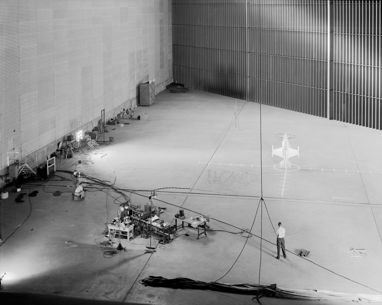
Wide shot of 40x 80 wind tunnel settling chamber with Lockheed XFV-1 model. Project engineer Mark Kelly (not shown). Remote controlled model flown in the settling chamber of the 40x80 wind tunnel. Electric motors in the model, controlled the counter-rotating propellers to test vertical takeoff. Test no. 71
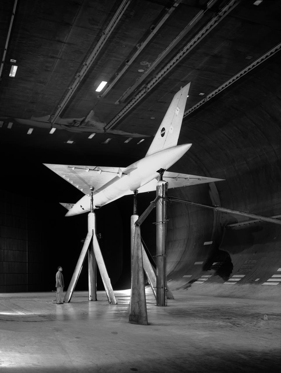
(11/12/1971) 3/4 rear view of swept 75% scale augmentor wing quest model being installed into the test section of the Ames 40x80 foot wind tunnel, overhead doors open.
Low Speed investigation of a supersonic transport model with delta wing and delta conard, in the 40x80 Wind Tunnel. R 975 T Zero angel of attack. 3/4 rear view from below.
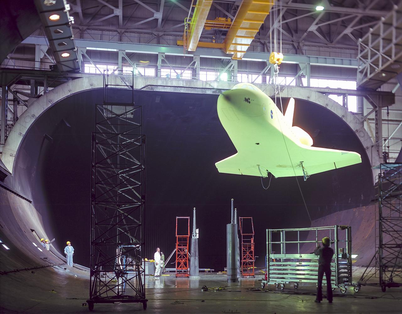
Installation of 1/3 scale model of space shuttle orbiter into the test section of the Ames 40x80 foot wind tunnel with overhead doors open.
Blunt Leading Edge Model in the Unitary Wind Tunnel high mach number test section.
Blunt Leading Edge Model in the Unitary Wind Tunnel high mach number test section.

Lockheed XFV-1 model. Project engineer Mark Kelly (not shown). Remote controlled model flown in the settling chamber of the 40x80 wind tunnel. Electric motors in the model, controlled the counter-rotating propellers to test vertical takeoff. Test no. 71
3% Space shuttle Acoustics model test-11-150 in 11ft. wind tunnel on PAL Ramp
3% Space shuttle Acoustics model test-11-150 in 11ft. wind tunnel on PAL Ramp
3% Space shuttle Acoustics model test-11-150 in 11ft. wind tunnel on PAL Ramp
3% Space shuttle Acoustics model test-11-150 in 11ft. wind tunnel on PAL Ramp
3% Space shuttle Acoustics model test-11-150 in 11ft. wind tunnel on PAL Ramp
3% Space shuttle Acoustics model test-11-150 in 11ft. wind tunnel on PAL Ramp
3% Space shuttle Acoustics model test-11-150 in 11ft. wind tunnel on PAL Ramp
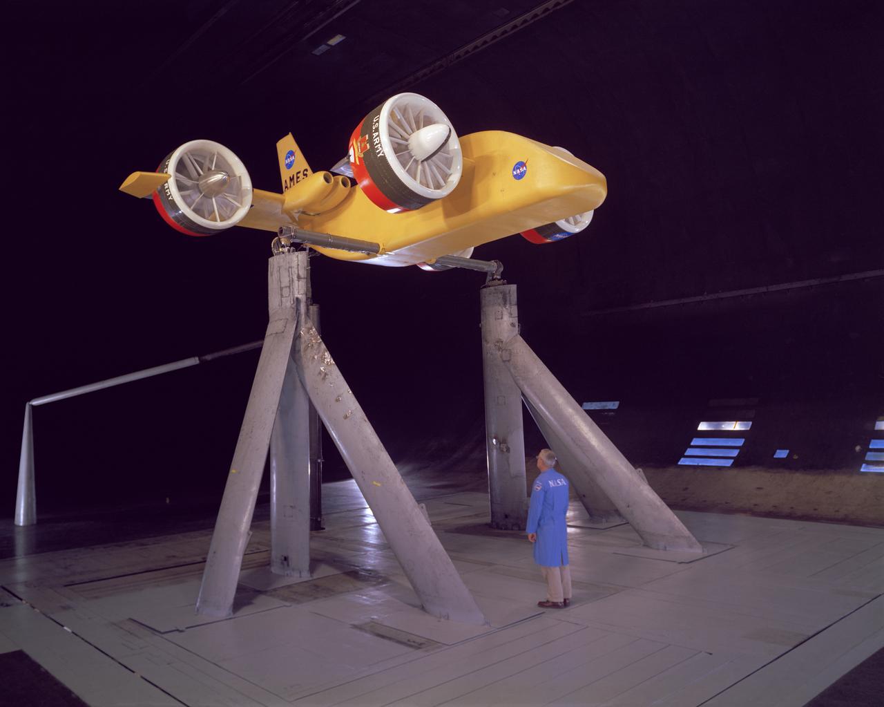
3/4 front view from below, showing Pods and Fan Rotating. March A. Zeiger standing in front. Tandem Dual Ducted Fan V/STOL Model in Ames 40x80 foot Wind Tunnel
Low Speed investigation of a supersonic transport model in the 40x80 Wind Tunnel. 03/01/1961 R 975 T Zero angel of attack. Supersonic transport with delta wing and delta conard. 3/4 front view.
3/4 front view of M-1-L inflatable recovery able lifting body model in Ames 40x80 foot wind tunnel. Mechanic, Ray Schmorance included in picture.
3% Space Shuttle Model Testing for Return to flight in the Ames 9X7ft wind tunnel test T97-0131 (IA-700B) with pressure sensitive paint
3% Space Shuttle Acoustics model test-11-150 in NASA Ames 11x11_foot. Transonic Wind Tunnel on PAL Ramp with Tim Steiger.
3% Space Shuttle Model Testing for Return to flight in the Ames 9X7ft wind tunnel test T97-0131 (IA-700B) with pressure sensitive paint
3% Space Shuttle Model Testing for Return to flight in the Ames 9X7ft wind tunnel test T97-0131 (IA-700B) with pressure sensitive paint
3% Space Shuttle Model Testing for Return to flight in the Ames 9X7ft wind tunnel test T97-0131 (IA-700B) with pressure sensitive paint
3% Space Shuttle Model Testing for Return to flight in the Ames 9X7ft wind tunnel test T97-0131 (IA-700B) with pressure sensitive paint
3% Space Shuttle Model Testing for Return to flight in the Ames 9X7ft wind tunnel test T97-0131 (IA-700B) with pressure sensitive paint
3% Space Shuttle Model Testing for Return to flight in the Ames 9X7ft wind tunnel test T97-0131 (IA-700B) with pressure sensitive paint
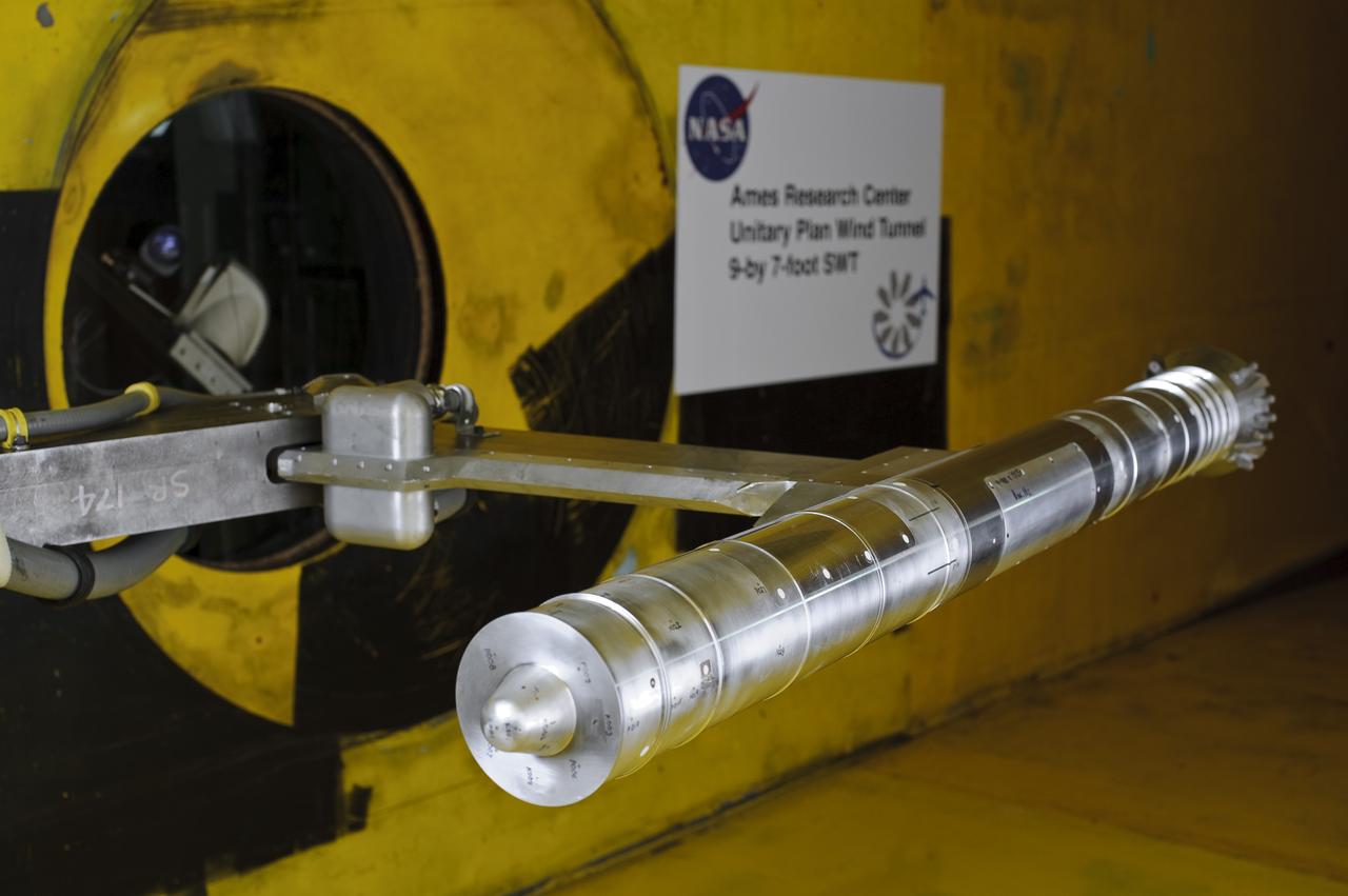
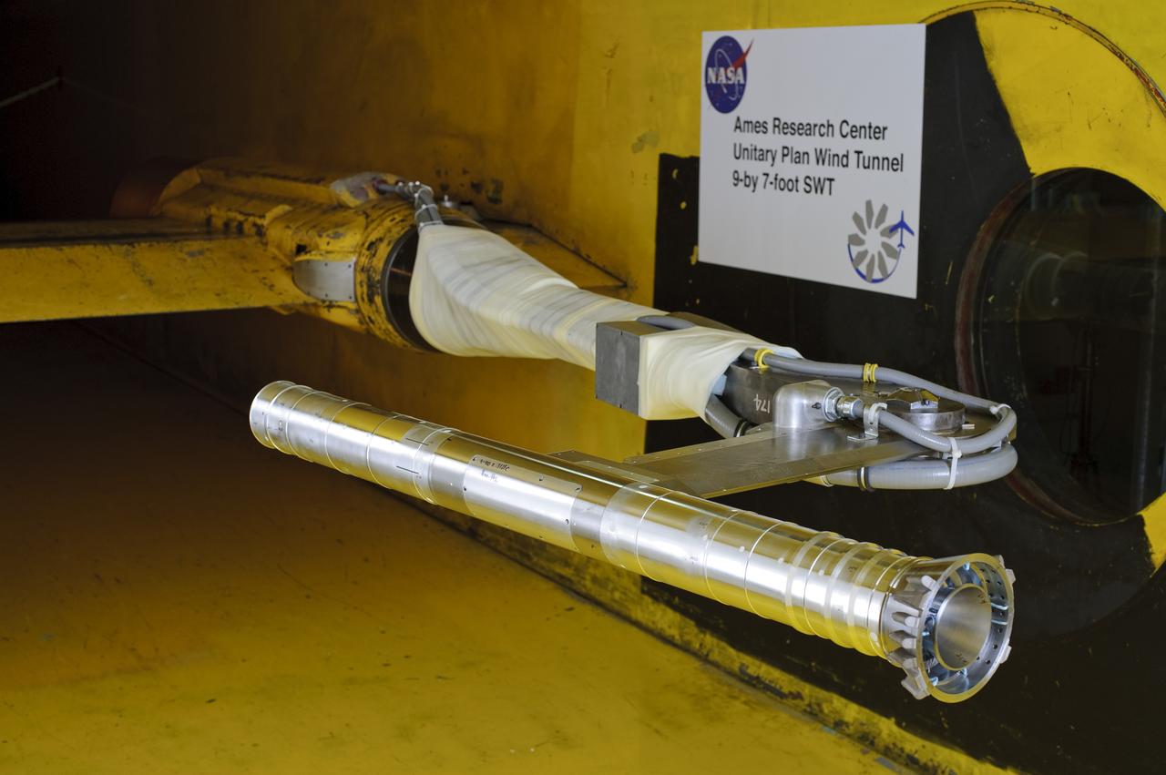
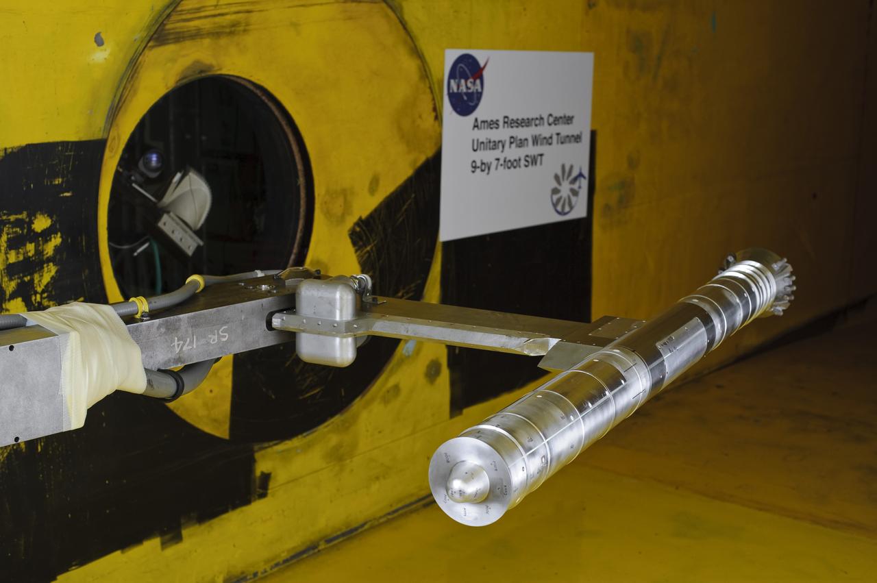
Scout Model in Unitary Wind Tunnel (UWT)
Parametric Inlet Model in 10x10 Wind Tunnel

3% Space Shuttle Model preparation in Ames Machine Shop for Return to flight test to be run in the Ames 9X7ft wind tunnel test T97-0131 (IA-700B)
3% Space Shuttle Model preparation in Ames Machine Shop for Return to flight test to be run in the Ames 9X7ft wind tunnel test T97-0131 (IA-700B)
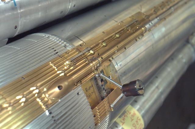
3% Space Shuttle Model preparation in Ames Machine Shop for Return to flight test to be run in the Ames 9X7ft wind tunnel test T97-0131 (IA-700B)
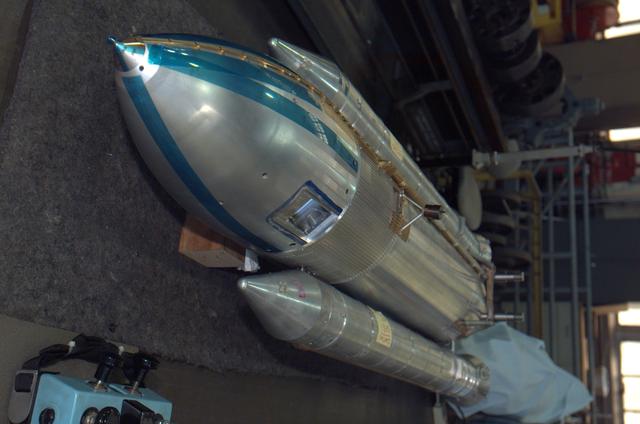
3% Space Shuttle Model preparation in Ames Machine Shop for Return to flight test to be run in the Ames 9X7ft wind tunnel test T97-0131 (IA-700B)
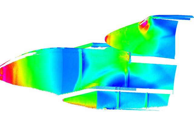
3% Space Shuttle Model Testing for Return to flight in the Ames 9X7ft wind tunnel test T97-0131 (IA-700B) showing data images created with pressure sensitive paint used on mode during the test run.
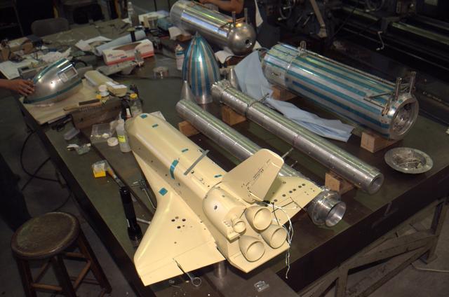
3% Space Shuttle Model preparation in Ames Machine Shop for Return to flight test to be run in the Ames 9X7ft wind tunnel test T97-0131 (IA-700B)
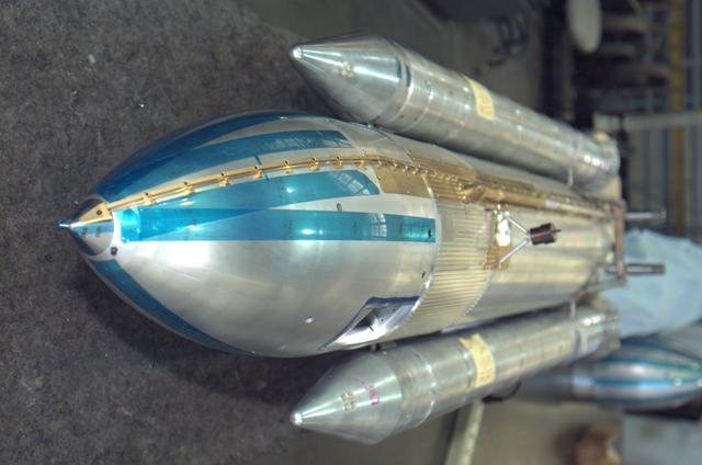
3% Space Shuttle Model preparation in Ames Machine Shop for Return to flight test to be run in the Ames 9X7ft wind tunnel test T97-0131 (IA-700B)
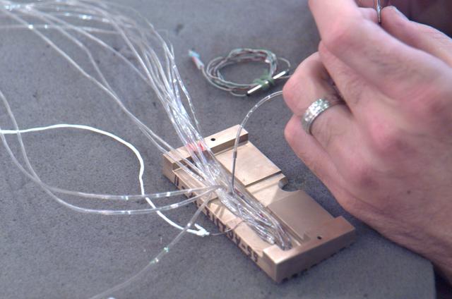
3% Space Shuttle Model preparation in Ames Machine Shop for Return to flight test to be run in the Ames 9X7ft wind tunnel test T97-0131 (IA-700B)
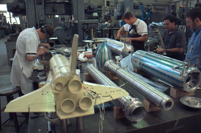
3% Space Shuttle Model preparation in Ames Machine Shop for Return to flight test to be run in the Ames 9X7ft wind tunnel test T97-0131 (IA-700B)
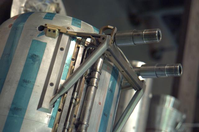
3% Space Shuttle Model preparation in Ames Machine Shop for Return to flight test to be run in the Ames 9X7ft wind tunnel test T97-0131 (IA-700B)
3% Space Shuttle Model preparation in Ames Machine Shop for Return to flight test to be run in the Ames 9X7ft wind tunnel test T97-0131 (IA-700B)
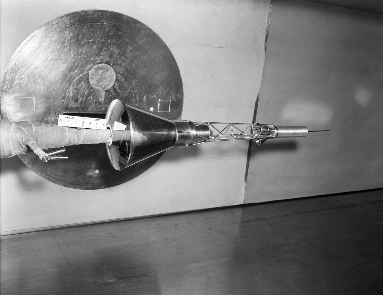
APOLLO STABILITY TEST IN THE 8X6 FOOT WIND TUNNEL - MODEL IS SHOWN WITH MODULE TOWER AND CANARDS
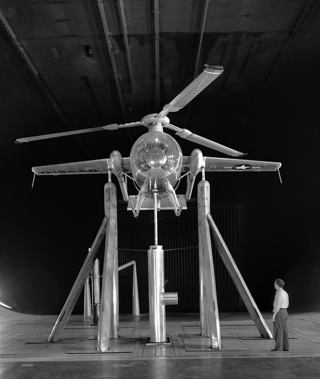
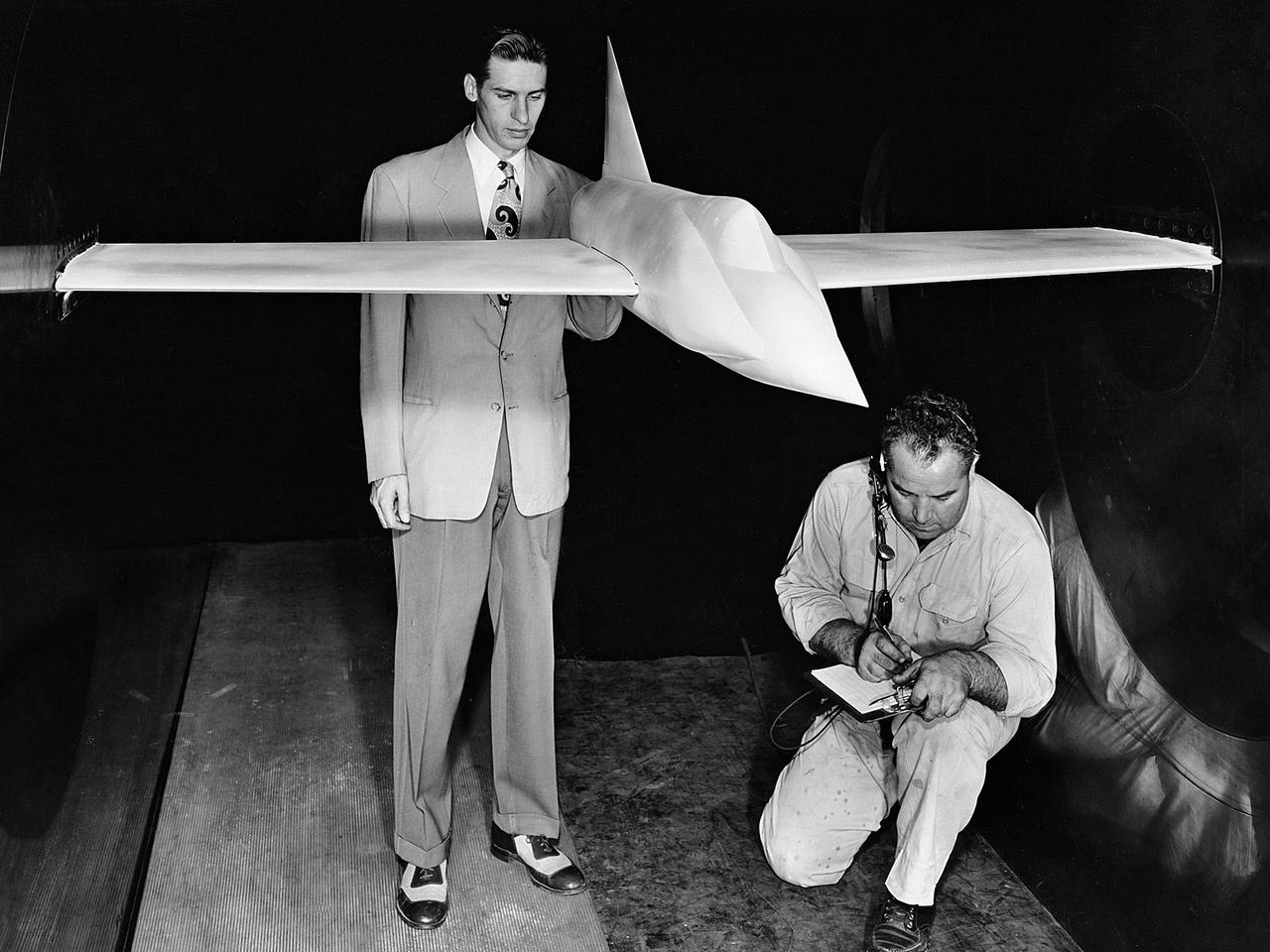
Foreword, front view of McDonnell Model XV-1 Convertiplane in the Ames 40x80 Foot Wind Tunnel. The McDonnell XV-1 was an experimental compound gyroplane developed for a joint research program between the United States Air Force and the United States Army to explore technologies to develop an aircraft that could take off and land like a helicopter but fly at faster airspeeds, similar to a conventional airplane. The XV-1 would reach a speed of 200 mph (322 km/h), faster than any previous rotorcraft, but the program was terminated due to the tip-jet noise and complexity of the technology which gave only a modest gain in performance.
Counter Rotating Propeller Model in the NASA Glenn 8x6-Foot Supersonic Wind Tunnel
(11/12/1971) 3/4 Scale swept augmentor wing Quest model being installed into the test section of the ames 40 x 80 foot wind tunnel, overhead doors open.
Model of Mercury being tested in the Unitary Plan Wind Tunnel.
Model of Mercury (Redstone booster) carrying the spacecraft in the Unitary Plan wind tunnel for testing.

Model of Mercury (Redstone booster) carrying the spacecraft in the Unitary Plan wind tunnel for testing.
A one-sixth scale model of the Mercury capsule being tested in the 300-mph 7 x 10-foot wind tunnel.
A 1/10th Scale Model of the X-15 research plane is prepared in Langley's 7 x 10 Foot Wind Tunnel for studies relating to spin characteristics. -- Photograph published in Winds of Change, 75th Anniversary NASA publication (page 66), by James Schultz.
Shown is a wind tunnel test of the Ares model for force/moment testing in support of the Ares/Clv integrated vehicle at Langley Research Center, Virginia. The image is extracted from a high definition video file and is the highest resolution available.

National Aeronautics and Space Administration (NASA) engineer Robert Jeracki prepares a Hamilton Standard SR-1 turboprop model in the test section of the 8- by 6-Foot Supersonic Wind Tunnel at the Lewis Research Center. Lewis researchers were analyzing a series of eight-bladed propellers in their wind tunnels to determine their operating characteristics at speeds up to Mach 0.8. The program, which became the Advanced Turboprop, was part of a NASA-wide Aircraft Energy Efficiency Program which was designed to reduce aircraft fuel costs by 50 percent. The ATP concept was different from the turboprops in use in the 1950s. The modern versions had at least eight blades and were swept back for better performance. After Lewis researchers developed the advanced turboprop theory and established its potential performance capabilities, they commenced an almost decade-long partnership with Hamilton Standard to develop, verify, and improve the concept. A series of 24-inch scale models of the SR-1 with different blade shapes and angles were tested in Lewis’ wind tunnels. A formal program was established in 1978 to examine associated noise levels, aerodynamics, and the drive system. The testing of the large-scale propfan was done on test rigs, in large wind tunnels, and, eventually, on aircraft.
National Aeronautics and Space Administration (NASA) researchers install a small-scale model of the capsule for Project Mercury in the 1- by 1-Foot Supersonic Wind Tunnel at the Lewis Research Center. NASA Lewis conducted a variety of tests for Project Mercury, including retrorocket calibration, escape tower engine performance, and separation of the capsule from simulated Atlas and Redstone boosters. The test of this capsule and escape tower model in the 1- by 1-foot tunnel were run in January and February 1960. The 1-by 1-Foot Supersonic Wind Tunnel had a 15-inch long test section, seen here, that was one foot wide and one foot high. The sides were made of glass to allow cameras to capture the supersonic air flow over the models. The tunnel could generate air flows from Mach 1.3 to 3.0. At the time, it was one of nine small supersonic wind tunnels at Lewis. These tunnels used the exhauster and compressor equipment of the larger facilities. The 1- by 1 tunnel, which began operating in the early 1950s, was built inside a test cell in the expansive Engine Research Building. During the 1950s the 1- by 1 was used to study a variety of inlets, nozzles, and cones for missiles and scramjets. The Mercury capsule tests were among the last at the facility for many years. The tunnel was mothballed in 1960. The 1- by 1 was briefly restored in 1972, then brought back online for good in 1979. The facility has maintained a brisk operating schedule ever since.
The 9x15 low speed tunnel tests take off and landing of aircraft. The laser velocimetry system for flow measurement show here, with the color blue and green lasers, measures engine exhaust that comes back up from the ground. The STOVL model n the 9x15 low speed wind tunnel, building 39, is similar to the British Harrier aircraft.
Technicians examine a scale model of the space shuttle used to obtain pressure data during tests in the 10- by 10-Foot Supersonic Wind Tunnel at the National Aeronautics and Space Administration (NASA) Lewis Research Center. Lewis researchers used the 10- by 10 tunnel extensively in the 1970s to study shuttle configurations in order to forecast conditions during an actual flight. These tests included analysis of the solid rocket boosters’ aerodynamics, orbiter forebody angle -of -attack and air speed, base heating for entire shuttle, and engine-out loads. The test seen in this photograph used a 3.5- percent scale aluminum alloy model of the entire launch configuration. The program was designed to obtain aerodynamic pressure data. The tests were part of a larger program to study possible trouble areas for the shuttle’s new Advanced Flexible Reusable Surface Insulation. The researchers obtained aeroacoustic data and pressure distributions from five locations on the model. Over 100 high-temperature pressure transducers were attached to the model. Other portions of the test program were conducted at Lewis’ 8- by 6-Foot Supersonic Wind Tunnel and the 11- by 11-Foot Transonic Wind Tunnel at Ames Research Center.
A .10-scale model of Convair’s XF-102 in the 8- by 6-Foot Supersonic Wind Tunnel at the National Advisory Committee for Aeronautics (NACA) Lewis Flight Propulsion Laboratory for jet exit studies. The XF-102 was a prototype of the F-102 Delta Dagger. The F-102 served as an interceptor against long range bombers from the Soviet Union. The aircraft was powered by a Pratt and Whitney J57 turbojet. The first prototype crashed two weeks after is first flight on October 24, 1953, just months after this photograph. Engineers then incorporated the fixed-wing design to reduce drag at supersonic speeds. The production model F-102 became the first delta-wing supersonic aircraft in operation. The 8- by 6-Foot Supersonic Wind Tunnel is used to study propulsion systems, including inlets and exit nozzles, combustion fuel injectors, flame holders, exit nozzles, and controls on ramjet and turbojet engines. Flexible sidewalls alter the tunnel’s nozzle shape to vary the Mach number during operation. A seven-stage axial compressor, driven by three electric motors that yield a total of 87,000 horsepower, generates air speeds from Mach 0.36 to 2.0.
A model of the General Dynamics YF-16 Fighting Falcon in the test section of the 8- by 6-Foot Supersonic Wind Tunnel at the National Aeronautics and Space Administration (NASA) Lewis Research Center. The YF-16 was General Dynamics response to the military’s 1972 request for proposals to design a new 20,000-pound fighter jet with exceptional acceleration, turn rate, and range. The aircraft included innovative design elements to help pilots survive turns up to 9Gs, a new frameless bubble canopy, and a Pratt and Whitney 24,000-pound thrust F-100 engine. The YF-16 made its initial flight in February 1974, just six weeks before this photograph, at Edwards Air Force Base. Less than a year later, the Air Force ordered 650 of the aircraft, designated as F-16 Fighting Falcons. The March and April 1974 tests in the 8- by 6-foot tunnel analyzed the aircraft’s fixed-shroud ejector nozzle. The fixed-nozzle area limited drag, but also limited the nozzle’s internal performance. NASA researchers identified and assessed aerodynamic and aerodynamic-propulsion interaction uncertainties associated the prototype concept. YF-16 models were also tested extensively in the 11- by 11-Foot Transonic Wind Tunnel and 9- by 7-Foot Supersonic Wind Tunnel at Ames Research Center and the 12-Foot Pressure Wind Tunnel at Langley Research Center.

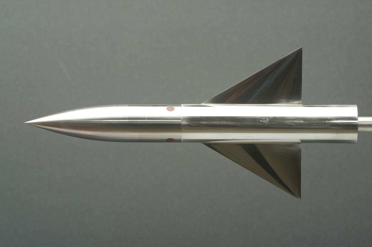
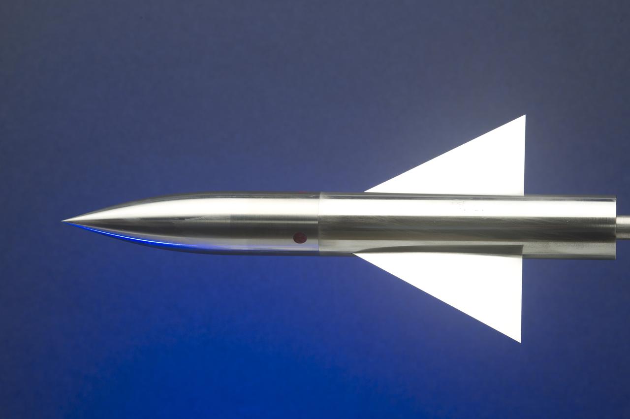
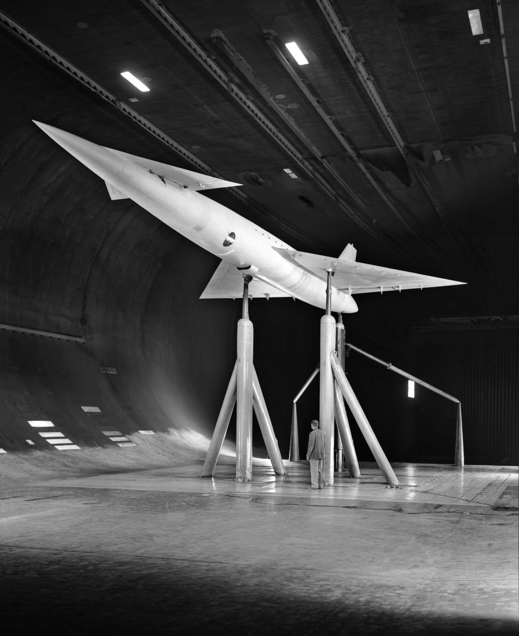
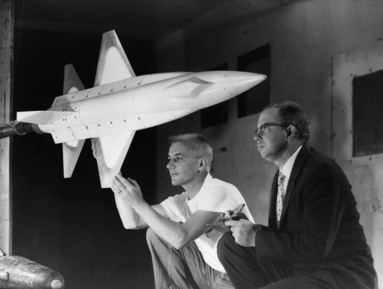
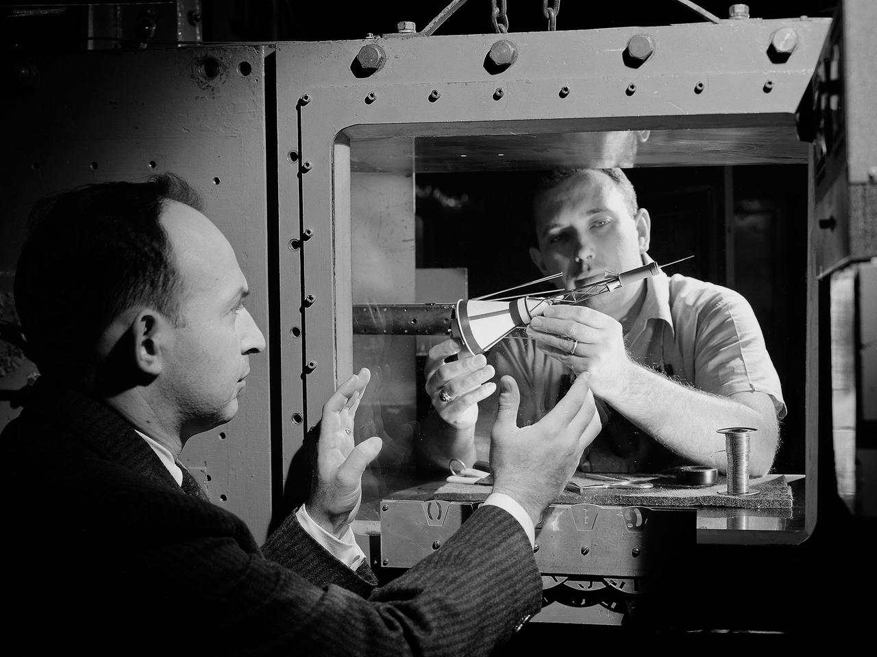
NASA Staff Dr.Darden, Matthew Overhold, Kathy Needleman, Robert Mack. Mach 3 Sonic Boom Model Wind Tunnel
National Aeronautics and Space Administration (NASA) researchers set up instrumentation on a 0.037- scale model of a Saturn booster in the 8- by 6-Foot Supersonic Wind Tunnel at the NASA Lewis Research Center. In October 1960 Lewis researchers John Allen and Robert Wasko began a 14-month investigation of the eight-engine booster’s base heating in the tunnel. The model resembled the Saturn C-1, but only the afterbody totally mimicked the C-1. The over-heating of the lower end, or base, of the booster can cause the engines to fail or introduce aerodynamic concerns. Base heating results from the rocket engines’ exhaust heat, the recirculation of that heat into the base, and the burning of combustibles. Large boosters, like the Saturn, employed clusters of rocket engines that add to the complexity of the base heating problem. The 8- by 6-foot tunnel investigations studied the Saturn at speeds from Mach 1.0 to 2.0 using liquid oxygen and JP-4 as propellants. Researchers found that the use of cooling air scoops and external flow deflectors produced significant decreases in base heating.
A researcher examines an Advanced Technology Transport model installed in the 8- by 6-Foot Supersonic Wind Tunnel at the National Aeronautics and Space Administration (NASA) Lewis Research Center. The Advanced Technology Transport concept was a 200-person supersonic transport aircraft that could cruise at Mach 0.9 to 0.98 with low noise and pollution outputs. General Electric and Pratt and Whitney responded to NASA Lewis’ call to design a propulsion system for the aircraft. The integration of the propulsion system with the airframe was one of the greatest challenges facing the designers of supersonic aircraft. The aircraft’s flow patterns and engine nacelles could significantly affect the performance of the engines. NASA Lewis researchers undertook a study of this 0.30-scale model of the Advanced Technology Transport in the 8- by 6-foot tunnel. The flow-through nacelles were located near the rear of the fuselage during the initial tests, seen here, and then moved under the wings for ensuing runs. Different engine cowl shapes were also analyzed. The researchers determined that nacelles mounted at the rear of the aircraft produced more efficient airflow patterns during cruising conditions at the desired velocities. The concept of the Advanced Technology Transport, nor any other US supersonic transport, has ever come to fruition. The energy crisis, environmental concerns, and inadequate turbofan technology of the 1970s were among the most significant reasons.
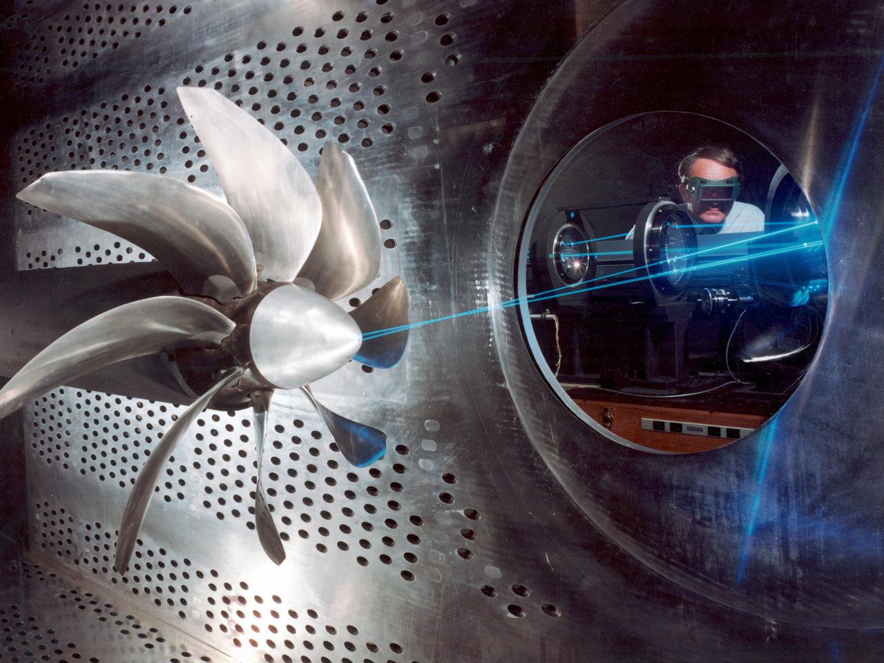
NASA Lewis Research Center researcher, John S. Sarafini, uses a laser doppler velocimeter to analyze a Hamilton Standard SR-2 turboprop design in the 8- by 6-Foot foot Supersonic Wind Tunnel. Lewis researchers were analyzing a series of eight-bladed propellers in their wind tunnels to determine their operating characteristics at speeds up to Mach 0.8. The program, which became the Advanced Turboprop (ATP), was part of a NASA-wide Aircraft Energy Efficiency Program undertaken to reduce aircraft fuel costs by 50 percent. The ATP concept was different from the turboprops in use in the 1950s. The modern versions had at least eight blades and were swept back for better performance. Bell Laboratories developed the laser doppler velocimeter technology in the 1960s to measure velocity of transparent fluid flows or vibration motion on reflective surfaces. Lewis researchers modified the device to measure the flow field of turboprop configurations in the transonic speed region. The modifications were necessary to overcome the turboprop’s vibration and noise levels. The laser beam was split into two beams which were crossed at a specific point. This permits researchers to measure two velocity components simultaneously. This data measures speeds both ahead and behind the propeller blades. Researchers could use this information as they sought to advance flow fields and to verify computer modeling codes.

X-15 launch techniques were investigated using on-twentieth scale models mounted in the 7x10 FT Tunnel. -- Photograph published in Winds of Change, 75th Anniversary NASA publication (page 67), by James Schultz. -- Photograph also published in Sixty Years of Aeronautical Research 1917-1977 - a NASA publication (page 49), by David A. Anderton.
Orion Capsule and Launch Abort System (LAS) installed in the NASA Glenn 8x6 Supersonic Wind Tunnel for testing. This test is an Aero Acoustic test of the LAS. Pictured is the calibration of the model's angle of attack
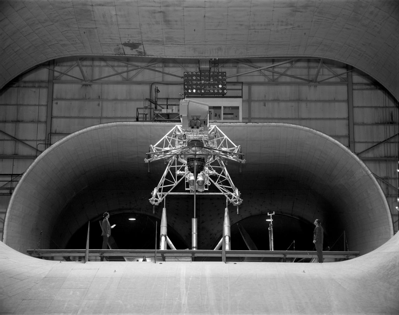
Concept model of the Lunar Excursion Module tested in the Full-Scale wind tunnel. -- Published in James R. Hansen, Spaceflight Revolution: NASA Langley Research Center From Sputnik to Apollo, (Washington: NASA, 1995), p. 356.-L69-670 Bell Lunar Landing Training Vehicle (LLTV): Following the crash of a sister Lunar Landing Training Vehicle at Ellington Field in Houston, Texas, the LLTV NASA 952 was sent from Houston to Langley for tests in the 30 x 60 Full Scale Tunnel. The LLTV was returned to Houston for further training use a short time later. NASA 952 is now on exhibit at the Johnson Space Center in Houston, Texas.
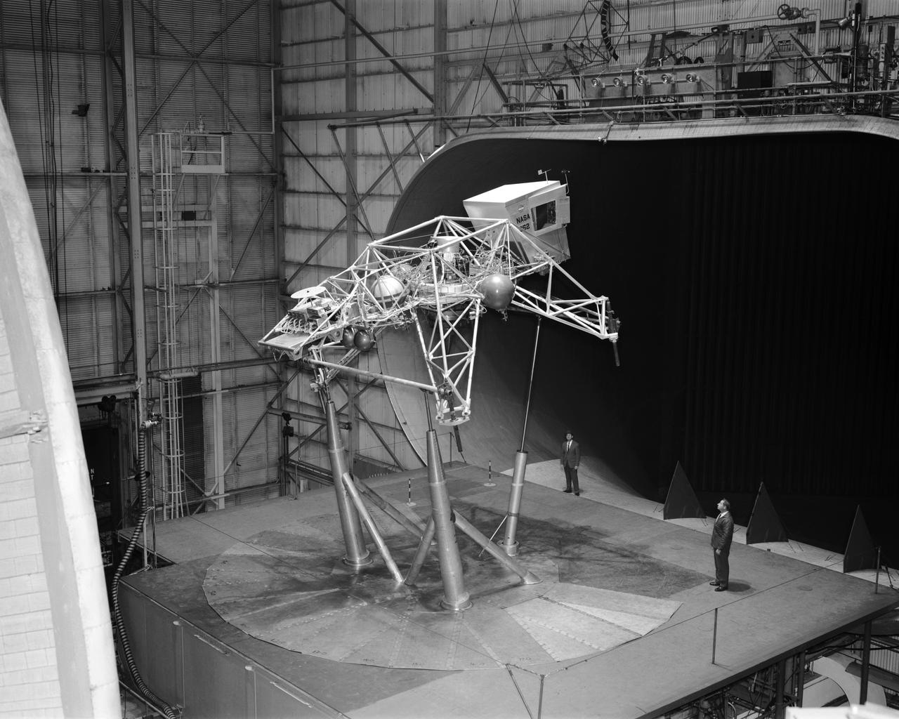
Concept model of the Lunar Excursion Module tested in the Full-Scale wind tunnel. -- Published in James R. Hansen, Spaceflight Revolution: NASA Langley Research Center From Sputnik to Apollo, (Washington: NASA, 1995), p. 356.-L69-670 Bell Lunar Landing Training Vehicle (LLTV): Following the crash of a sister Lunar Landing Training Vehicle at Ellington Field in Houston, Texas, the LLTV NASA 952 was sent from Houston to Langley for tests in the 30 x 60 Full Scale Tunnel. The LLTV was returned to Houston for further training use a short time later. NASA 952 is now on exhibit at the Johnson Space Center in Houston, Texas.
2.8% Ares I Acoustic Reentry Wind Tunnel Model in Ames 9X7ft Supersonic Wind Tunnel test-97-0193; model flying backwards in tunnel
2.8% Ares I Acoustic Reentry Wind Tunnel Model in Ames 9X7ft Supersonic Wind Tunnel test-97-0193; model flying backwards in tunnel
2.8% Ares I Acoustic Reentry Wind Tunnel Model in Ames 9X7ft Supersonic Wind Tunnel test-97-0193; model flying backwards in tunnel
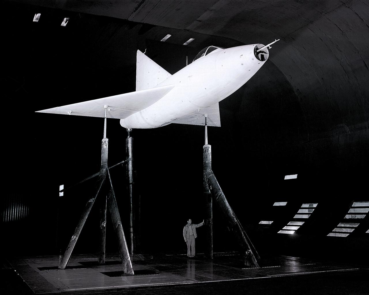
Application of blowing type boundry-layer control to the leading and trailing edge flaps of a 52 deg swept wing. 3/4 view of Aspect Ratio 2.8, taper ratio .17, 45 deg swept back wing model -3/4 front view

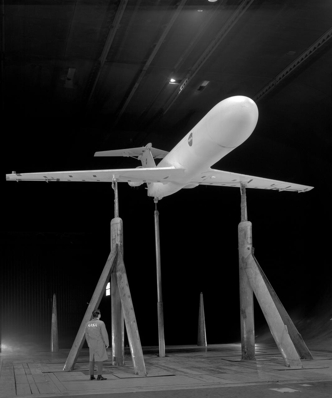
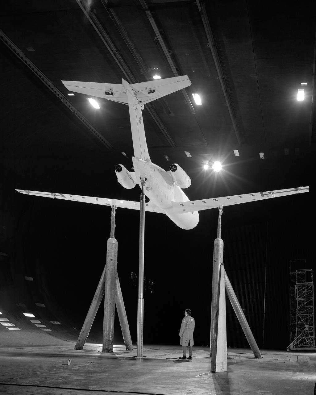
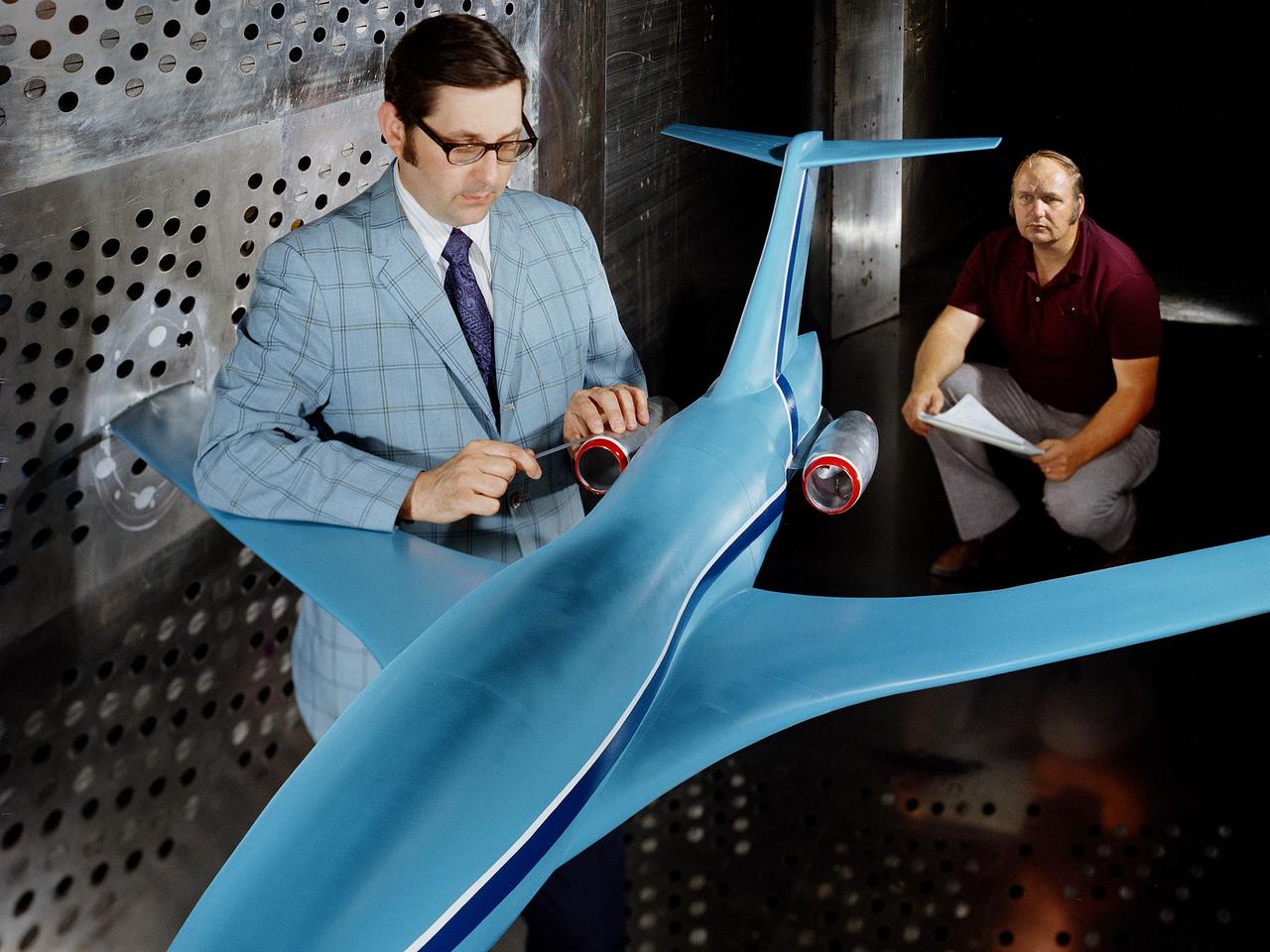
Overhead view of Boeing Super Sonic Transport , wings un-swept.
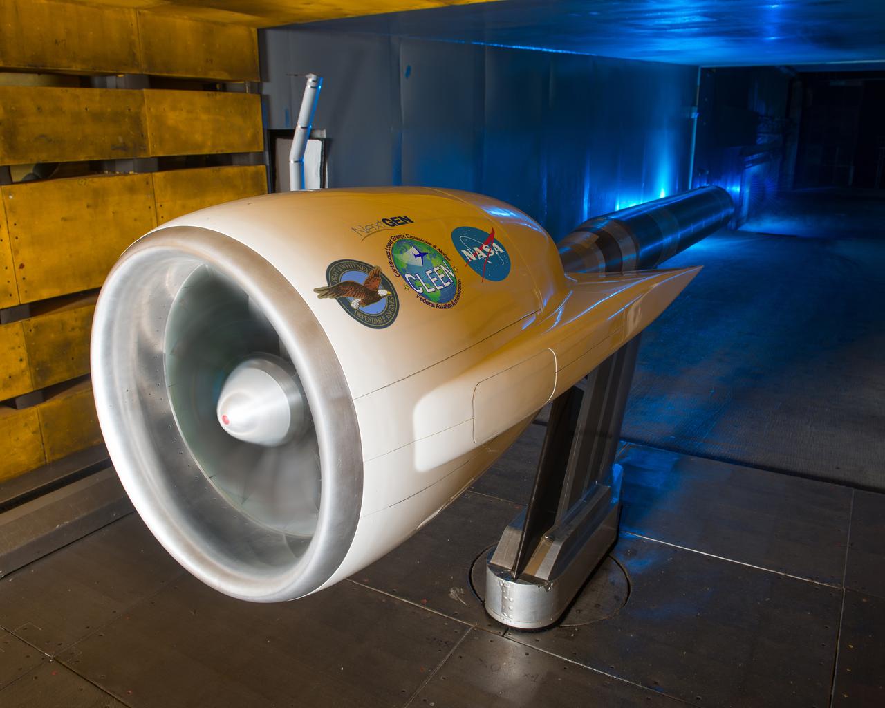
Ultra High Bypass Integrated System Test Testing of an Ultra High Bypass Ratio Turbofan model in the 9-by 15-Foot Low Speed Wind Tunnel. Pratt & Whitney designed the experimental engine to meet new efficiency and noise reduction targets for commercial aircraft set by NASA and the Federal Aviation Administration. The 9-by 15 tests analyzed two noise reduction technologies.
A Highly Maneuverable Aircraft Technology (HiMAT) inlet model installed in the test section of the 8- by 6-Foot Supersonic Wind Tunnel at the National Aeronautics and Space Administration (NASA) Lewis Research Center. Engineers at the Ames Research Center, Dryden Flight Research Center, and Rockwell International designed two pilotless subscale HiMAT vehicles in the mid-1970s to study new design concepts for fighter aircraft in the transonic realm without risking the lives of test pilots. The aircraft used sophisticated technologies such as advanced aerodynamics, composite materials, digital integrated propulsion control, and digital fly-by-wire control systems. In late 1977 NASA Lewis studied the HiMAT’s General Electric J85-21 jet engine in the Propulsion Systems Laboratory. The researchers charted the inlet quality with various combinations anti-distortion screens. HiMAT employed a relatively short and curved inlet compared to actual fighter jets. In the spring of 1979, Larry Smith led an in-depth analysis of the HiMAT inlet in the 8- by 6 tunnel. The researchers installed vortex generators to battle flow separation in the diffuser. The two HiMAT aircraft performed 11 hours of flying over the course of 26 missions from mid-1979 to January 1983 at Dryden and Ames. Although the HiMAT vehicles were considered to be overly complex and expensive, the program yielded a wealth of data that would validate computer-based design tools.
A researcher at the National Advisory Committee for Aeronautics (NACA) Lewis Flight Propulsion Laboratory checks the setup of a RJM-2 ramjet model in the test section of the 8- by 6-Foot Supersonic Wind Tunnel. The 8- by 6 was not only the laboratory’s first large supersonic wind tunnel, but it was also the NACA’s first facility capable of testing an operating engine at supersonic speeds. The 8- by 6-foot tunnel has been used to study engine inlets, fuel injectors, flameholders, exit nozzles, and controls on ramjet and turbojet propulsion systems. The 8-foot wide and 6-foot tall test section consisted of 1-inch thick steel plates with hatches on the floor and ceiling to facilitate the installation of the test article. The two windows seen on the right wall allowed photographic equipment to be set up. The test section was modified in 1956 to accommodate transonic research. NACA engineers drilled 4,700 holes into the test section walls to reduce transonic pressure disturbances and shock waves. NACA Lewis undertook an extensive research program on ramjets in the 1940s using several of its facilities. Ramjets provide a very simple source of propulsion. They are basically a tube which ingests high speed air, ignites it, and then expels the heated air at a significantly higher velocity. Ramjets are extremely efficient and powerful but can only operate at high speeds. Therefore, they require a booster rocket or aircraft drop to accelerate them to high speeds before they can operate.
A technician prepares a 2.25 percent scale model of the space shuttle for a base heat study in the 10- by 10-Foot Supersonic Wind Tunnel at the National Aeronautics and Space Administration (NASA) Lewis Research Center. This space shuttle project, begun here in July 1976, was aimed at evaluating base heating and pressure prior to the Shuttle’s first lift-off scheduled for 1979. The space shuttle was expected to experience multifaceted heating and pressure distributions during the first and second stages of its launch. Engineers needed to understand these issues in order to design proper thermal protection. The test’s specific objectives were to measure the heat transfer and pressure distributions around the orbiter’s external tank and solid rocket afterbody caused by rocket exhaust recirculation and impingement, to measure the heat transfer and pressure distributions caused by rocket exhaust-induced separation, and determine gas recovery temperatures using gas temperature probes and heated base components. The shuttle model’s main engines and solid rockets were first fired and then just the main engines to simulate a launch during the testing. Lewis researchers conducted 163 runs in the 10- by 10 during the test program.
M-2 lifting body wind tunnel model with wind tunnel mechanic Chuck Greco. Model mounted on special support designed for lifting body models. Flaps and elevons visible.
In May and June, NASA researchers tested a 7-foot wing model in the 14-by-22-Foot Subsonic Wind Tunnel at NASA’s Langley Research Center in Hampton, Virginia. The team collected data on critical propeller-wing interactions over the course of several weeks
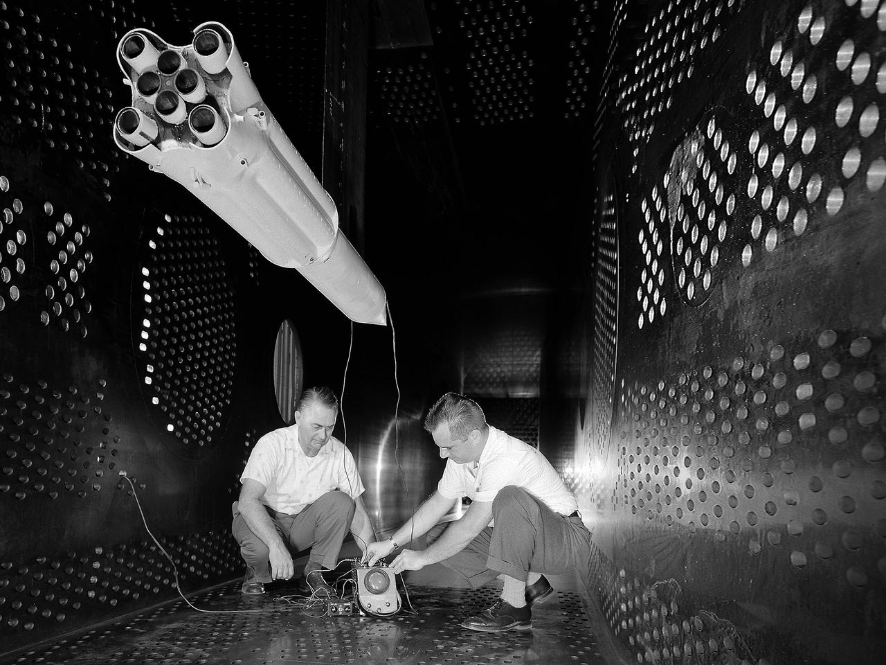
Researchers check the setup of a multi-nozzle base flow model in the 10- by 10-Foot Supersonic Wind Tunnel at the National Aeronautics and Space Administration (NASA) Lewis Research Center. NASA researchers were struggling to understand the complex flow phenomena resulting from the use of multiple rocket engines. Robert Wasko and Theodore Cover of the Advanced Development and Evaluation Division’s analysis and operations sections conducted a set of tests in the 10- by 10 tunnel to further understand the flow issues. The Lewis researchers studied four and five-nozzle configurations in the 10- by 10 at simulated altitudes from 60,000 to 200,000 feet. The nozzles were gimbaled during some of the test runs to simulate steering. The flow field for the four-nozzle clusters was surveyed in the center and the lateral areas between the nozzles, whereas the five-nozzle cluster was surveyed in the lateral area only.
A researcher at the National Aeronautics and Space Administration (NASA) Lewis Research Center examines a small-scale model of the Gemini capsule in the 10- by 10-Foot Supersonic Wind Tunnel test section. Gemini was added to NASA’s manned space program after its predecessor, Mercury, and its antecedent, Apollo, were already established. Gemini was a transitional mission designed provide the astronauts with practice docking with other spacecraft and withstanding durations in space up to two weeks. The program was officially announced on December 7, 1961, but planning began in mid-1959. It was named Gemini after the zodiac twins because of the spacecraft’s two passenger capacity. The Gemini Program was the first program to start at the new Manned Spacecraft Center in Houston, now the Johnson Space Center. Unlike Mercury and Apollo, Lewis had very little involvement with the Gemini Program. This model was tested in the 10- by 10 tunnel for several weeks in September 1962. Lewis began managing the Agena second-stage rocket program shortly after this photograph was taken. Agenas were used to launch a variety of spacecraft and satellites in the 1960s. They were also used on several Gemini missions to provide targets for the astronauts to practice their rendezvous maneuvers. Gemini had two unmanned and ten manned flights in 1965 and 1966. These yielded the first spacewalks, long-duration space missions, first onboard computer, docking with a second spacecraft, and rendezvous maneuvers.
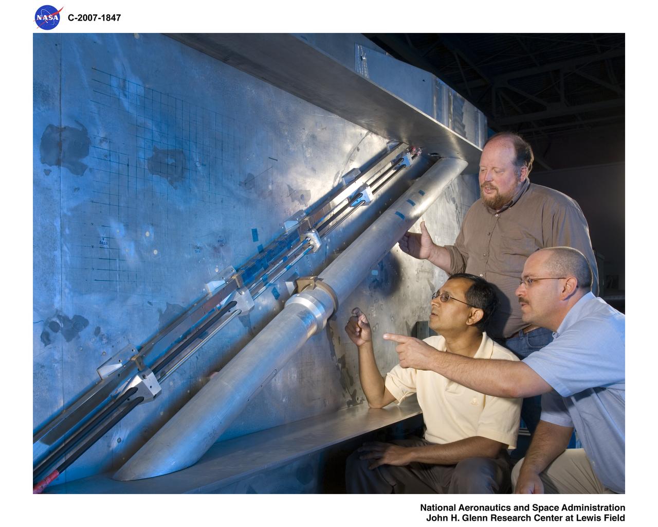
Wind Tunnel Cable Tray Model
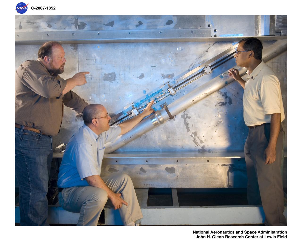
Wind Tunnel Cable Tray Model
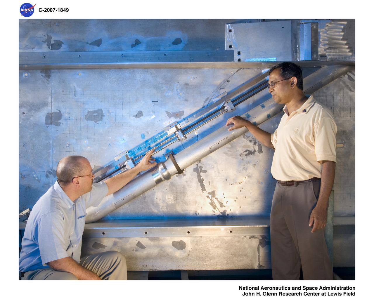
Wind Tunnel Cable Tray Model
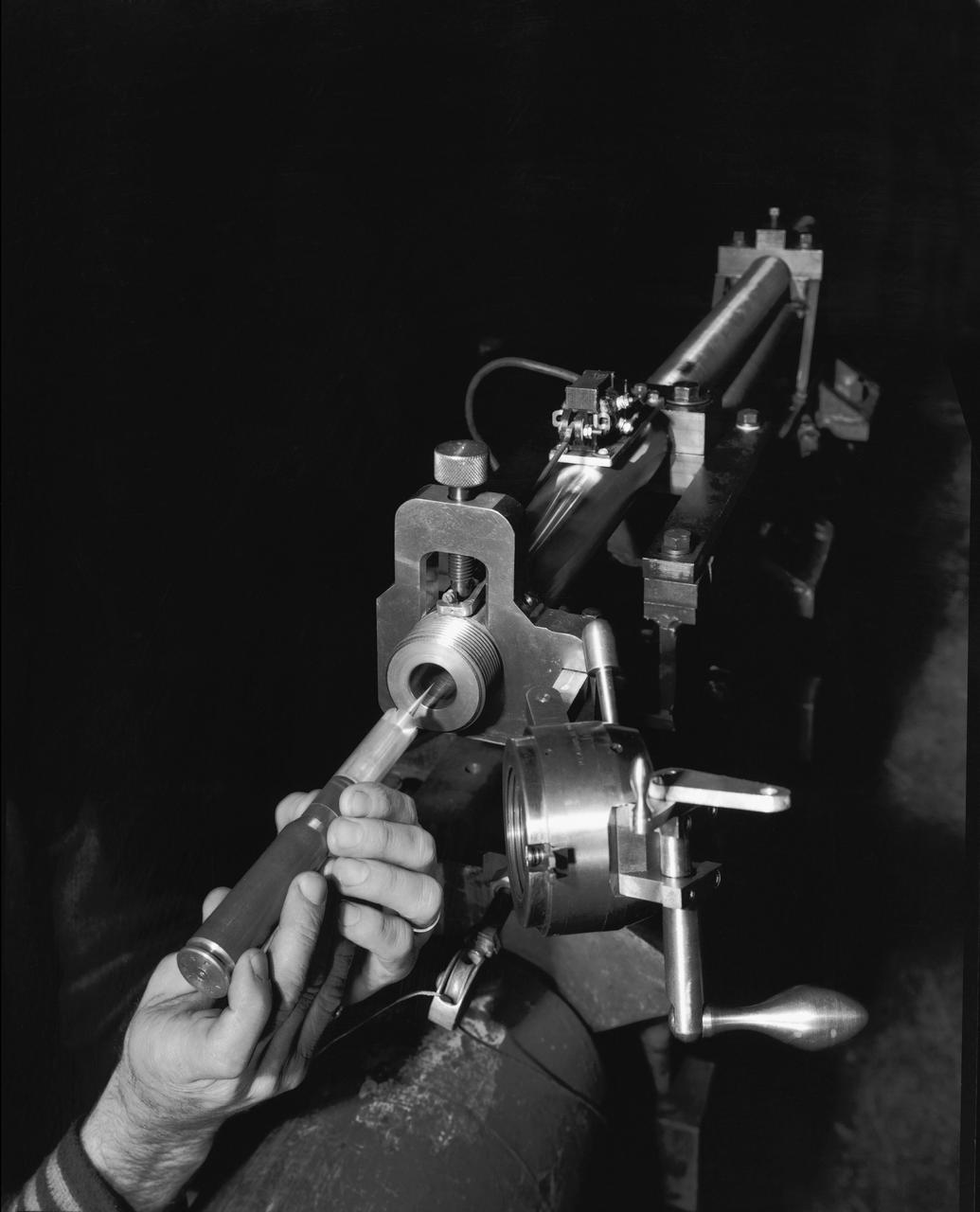
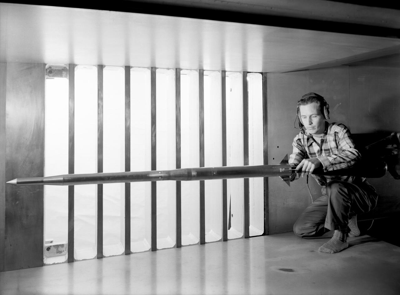
Supersonic Free Flight Wind Tunnel 620 gun and model; model, sabot and cartridge assembly and ready for firing in the supersonic free flight tunnel
Robert Cubbison examines a model of the Lockheed YF-12 Blackbird in the test section of the 10- by 10-Foot Supersonic Wind Tunnel at the National Aeronautics and Space Administration (NASA) Lewis Research Center. The YF-12 was an experimental fighter version of Lockheed’s A-12 reconnaissance aircraft which had been developed into the renowned SR-71 Blackbird. NASA possessed two YF-12s at its Dryden Flight Research Center which could be used by researchers at all the NASA centers. During its nine-year life, the Dryden’s YF-12 research program logged 297 flights with approximately 450 flight hours. Lewis researchers were studying the YF-12’s inlet airflow in the 10- by 10-foot wind tunnel in late 1977. The advanced supersonic cruise aircraft of the time used mixed-compression inlets. These types of inlets were prone to flameout during atmospheric disturbances. Researchers at Lewis and Dryden developed a program to study these flameouts by artificially introducing flow disturbances. Testing at Dryden with a specially-equipped YF-12 aircraft yielded limited results. Lewis’ tests in the 10- by 10 were unsuccessful at inducing upstream disturbances. The researchers used two methods—a falling plate and a servo-driven wing.
Parametric Inlet Model in 10x10 Wind Tunnel
Parametric Inlet Model in 10x10 Wind Tunnel