Forward overhead view of lift fan transport model, with two, of a possible six, high pressure ratio wing lift fans. Lift Fan Model In 40 X 80 Wind Tunnel; Test 40-347
Lift Fan Model In Ames 40 X 80 Wind Tunnel.
With a small stabilization parachute trailing behind, the X-40 sub-scale technology demonstrator is suspended under a U.S. Army CH-47 Chinook cargo helicopter during a captive-carry test flight at NASA's Dryden Flight Research Center, Edwards, California. The captive carry flights are designed to verify the X-40's navigation and control systems, rigging angles for its sling, and stability and control of the helicopter while carrying the X-40 on a tether. Following a series of captive-carry flights, the X-40 made free flights from a launch altitude of about 15,000 feet above ground, gliding to a fully autonomous landing. The X-40 is an unpowered 82 percent scale version of the X-37, a Boeing-developed spaceplane designed to demonstrate various advanced technologies for development of future lower-cost access to space vehicles.
With a small stabilization parachute trailing behind, the X-40 sub-scale technology demonstrator is suspended under a U.S. Army CH-47 Chinook cargo helicopter during a captive-carry test flight
The X-40 sub-scale technology demonstrator is suspended under a U.S. Army CH-47 Chinook cargo helicopter during a captive-carry test flight at NASA's Dryden Flight Research Center, Edwards, California. The captive carry flights are designed to verify the X-40's navigation and control systems, rigging angles for its sling, and stability and control of the helicopter while carrying the X-40 on a tether. Following a series of captive-carry flights, the X-40 made free flights from a launch altitude of about 15,000 feet above ground, gliding to a fully autonomous landing. The X-40 is an unpowered 82 percent scale version of the X-37, a Boeing-developed spaceplane designed to demonstrate various advanced technologies for development of future lower-cost access to space vehicles.
The X-40 sub-scale technology demonstrator is suspended under a U.S. Army CH-47 Chinook cargo helicopter during a captive-carry test flight at NASA's Dryden Flight Research Center, Edwards, California.
A U.S. Army CH-47 Chinook helicopter slowly lowers the X-40 sub-scale technology demonstrator to the ground under the watchful eyes of ground crew at the conclusion of a captive-carry test flight at NASA's Dryden Flight Research Center, Edwards, California. Several captive-carry flights were conducted to check out all operating systems and procedures before the X-40 made its first free flight at Edwards, gliding to a fully-autonomous approach and landing on the Edwards runway. The X-40 is an unpowered 82 percent scale version of the X-37, a Boeing-developed spaceplane designed to demonstrate various advanced technologies for development of future lower-cost access to space vehicles. Flight tests of the X-40 are designed to reduce the risks associated with research flights of the larger, more complex X-37.
A U.S. Army CH-47 Chinook helicopter slowly lowers the X-40 sub-scale technology demonstrator to the ground under the watchful eyes of ground crew at the conclusion of a captive-carry test flight
The X-40 sub-scale technology demonstrator and its U.S. Army CH-47 Chinook helicopter mothership fly over a dry lakebed runway during a captive-carry test flight from NASA's Dryden Flight Research Center, Edwards, California. The X-40 is attached to a sling which is suspended from the CH-47 by a 110-foot-long cable during the tests, while a small parachute trails behind to provide stability. The captive carry flights are designed to verify the X-40's navigation and control systems, rigging angles for its sling, and stability and control of the helicopter while carrying the X-40 on a tether. Following a series of captive-carry flights, the X-40 made free flights from a launch altitude of about 15,000 feet above ground, gliding to a fully autonomous landing. The X-40 is an unpowered 82 percent scale version of the X-37, a Boeing-developed spaceplane designed to demonstrate various advanced technologies for development of future lower-cost access to space vehicles.
The X-40 sub-scale technology demonstrator and its U.S. Army CH-47 Chinook helicopter mothership fly over a dry lakebed runway during a captive-carry test flight at NASA's Dryden Flight Research Center
(11/12/1971) 3/4 Scale swept augmentor wing Quest model being installed into the test section of the ames 40 x 80 foot wind tunnel, overhead doors open.
A71-8290. Swept Augmentor Wing Model Being Installed Into The Test Section Of The Ames 40 X 80 Foot Wind Tunnel.
Wranglers steadied the X-40A at NASA's Dryden Flight Research Center, Edwards, California, March 14, 2001, as the experimental craft was carried to 15,000 feet for an unpiloted glide flight. The unpiloted X-40 is a risk-reduction vehicle for the X-37, which is intended to be a reusable space vehicle.  NASA's Marshall Space Flight Center in Huntsville, Ala, manages the X-37 project. At Dryden, the X-40A will undergo a series of ground and air tests to reduce possible risks to the larger X-37, including drop tests from a helicopter to check guidance and navigation systems planned for use in the X-37. The X-37 is designed to demonstrate technologies in the orbital and reentry environments for next-generation reusable launch vehicles that will increase both safety and reliability, while reducing launch costs from $10,000 per pound to $1,000 per pound.
Wranglers steadied the X-40A at NASA's Dryden Flight Research Center, Edwards, California, March 14, 2001, as the experimental craft was carried to 15,000 feet for an unpiloted glide flight
First flight at NASA's Dryden Flight Research Center for the X-40A was a 74 second glide from 15,000 feet on March 14, 2001. The unpiloted X-40 is a risk-reduction vehicle for the X-37, which is intended to be a reusable space vehicle.  NASA's Marshall Space Flight Center in Huntsville, Ala, manages the X-37 project. At Dryden, the X-40A will undergo a series of ground and air tests to reduce possible risks to the larger X-37, including drop tests from a helicopter to check guidance and navigation systems planned for use in the X-37. The X-37 is designed to demonstrate technologies in the orbital and reentry environments for next-generation reusable launch vehicles that will increase both safety and reliability, while reducing launch costs from $10,000 per pound to $1,000 per pound.
First flight at NASA's Dryden Flight Research Center for the X-40A was a 74 second glide from 15,000 feet on March 14, 2001
Ground crewmen help guide the alignment of the X-40 technology demonstrator as the experimental craft is gently lowered to the ground by a U.S. Army CH-47 Chinook cargo helicopter following a captive-carry test flight at NASA's Dryden Flight Research Center, Edwards, California. The X-40 is an unpowered 82 percent scale version of the X-37, a Boeing-developed spaceplane designed to demonstrate various advanced technologies for development of future lower-cost access to space vehicles. The X-37 will be carried into space aboard a space shuttle and then released to perform various maneuvers and a controlled re-entry through the Earth's atmosphere to an airplane-style landing on a runway, controlled entirely by pre-programmed computer software. Following a series of captive-carry flights, the X-40 made several free flights from a launch altitude of about 15,000 feet above ground, gliding to a fully autonomous landing. The captive carry flights helped verify the X-40's navigation and control systems, rigging angles for its sling, and stability and control of the helicopter while carrying the X-40 on a tether.
Ground crewmen help guide the alignment of the X-40A as the experimental craft is gently lowered to the ground by a U.S. Army CH-47 Chinook helicopter following a captive-carry test flight
A worker attaches covers for the nose pitot boom before removing the unpiloted X-40 from the runway at Edwards Air Force Base, California, following its successful free-flight on March 14, 2001. The unpiloted X-40 is a risk-reduction vehicle for the X-37, which is intended to be a reusable space vehicle. NASA's Marshall Space Flight Center in Huntsville, Ala, manages the X-37 project. At Dryden, the X-40A will undergo a series of ground and air tests to reduce possible risks to the larger X-37, including drop tests from a helicopter to check guidance and navigation systems planned for use in the X-37. The X-37 is designed to demonstrate technologies in the orbital and reentry environments for next-generation reusable launch vehicles that will increase both safety and reliability, while reducing launch costs from $10,000 per pound to $1,000 per pound.
A worker attaches covers for the nose pitot boom before removing the unpiloted X-40 from the runway at Edwards Air Force Base, California, following its successful free-flight on March 14, 2001
The first X-45A Unmanned Combat Air Vehicle (UCAV) technology demonstrator completed its sixth flight on Dec. 19, 2002, raising its landing gear in flight for the first time. The X-45A flew for 40 minutes and reached an airspeed of 195 knots and an altitude of 7,500 feet.  Dryden is supporting the DARPA/Boeing team in the design, development, integration, and demonstration of the critical technologies, processes, and system attributes leading to an operational UCAV system. Dryden support of the X-45A demonstrator system includes analysis, component development, simulations, ground and flight tests.
The first X-45A Unmanned Combat Air Vehicle (UCAV) technology demonstrator completed its sixth flight on Dec. 19, 2002, raising its landing gear in flight for the first time. The X-45A flew for 40 minutes and reached an airspeed of 195 knots
This is an X-band Synthetic Aperture Radar image spanning an area of about 20 kilometers by 40 kilometers 12 miles by 25 miles of NASA Kennedy Space Center, Florida.
Space Radar Image of Kennedy Space Center, Florida
55% Sharc Model Test, 40 x 80 W.T. Test-597 (Subsonic High Alpha Res Concept) Moved from Model Shop to 40 x 80 W.T.
ARC-1994-AC94-0480-48
55% Sharc Model Test, 40 x 80 W.T. Test-597 (Subsonic High Alpha Res Concept) Moved from Model Shop to 40 x 80 W.T.
ARC-1994-AC94-0480-42
One of the first helicopter tests in the 40 x 80 wind tunnel.  John McCloud, pictured, started helicopter work in the 40 x 80.  Test 150. Testing the effects of camber on rotor blades.
Rotor Blade Test in the NACA Ames 40x80 foot Wind Tunnel.
55% Sharc Model Test, 40 x 80 W.T. Test-597 (Subsonic High Alpha Res Concept) Moved from Model Shop to 40 x 80 W.T.
ARC-1994-AC94-0480-43
Wright Flyer Replica Test-40-0047:  40 x 80 ft. Wind Tunnel.
ARC-1969-AC99-0030-69
Wright Flyer Replica Test-40-0047:  40 x 80 ft. Wind Tunnel.
ARC-1969-AC99-0030-64
Wright Flyer Replica Test-40-0047:  40 x 80 ft. Wind Tunnel.
ARC-1969-AC99-0030-75
Wright Flyer Replica Test-40-0047:  40 x 80 ft. Wind Tunnel.  test crew
ARC-1999-AC99-0030-81
Lear Jet in 40 x 80 ft. Wind Tunnel with Ed Varrette.  Angle of Attack=40 degrees.
ARC-1968-A-40937
Wright Flyer Replica Test-40-0047:  40 x 80 ft. Wind Tunnel.  AIAA crew
ARC-1969-AC99-0030-83
Wright Flyer Replica Test-40-0047:  40 x 80 ft. Wind Tunnel.
ARC-1969-AC99-0030-79
Wright Flyer Replica Test-40-0047:  40 x 80 ft. Wind Tunnel.
ARC-1969-AC99-0030-65
Wright Flyer Replica Test-40-0047:  40 x 80 ft. Wind Tunnel.
ARC-1969-AC99-0030-72
Wright Flyer Replica Test-40-0047:  40 x 80 ft. Wind Tunnel.
ARC-1969-AC99-0030-62
Wright Flyer Replica Test-40-0047:  40 x 80 ft. Wind Tunnel.
ARC-1969-AC99-0030-63
Space X 1st Stage Arrival at Complex 40
2010-4336
Space X 1st Stage Arrival at Complex 40
2010-4337
Space X 1st Stage Arrival at Complex 40
2010-4339
Space X 1st Stage Arrival at Complex 40
2010-4342
Space X 1st Stage Arrival at Complex 40
2010-4346
Space X 1st Stage Arrival at Complex 40
2010-4344
Space X 1st Stage Arrival at Complex 40
2010-4340
Space X 1st Stage Arrival at Complex 40
2010-4343
Space X 1st Stage Arrival at Complex 40
2010-4338
Space X 1st Stage Arrival at Complex 40
2010-4335
Space X 1st Stage Arrival at Complex 40
2010-4334
Space X 1st Stage Arrival at Complex 40
2010-4341
X-40A Free Flight #5. The unpowered X-40A, an 85 percent scale risk reduction version of the proposed X-37, proved the capability of an autonomous flight control and landing system in a series of glide flights at NASA's Dryden Flight Research Center in California. NASA's Marshall Space Flight Center in Huntsville, Alabama, manages the X-37 project. At Dryden, the X-40A underwent a series of ground and air tests to reduce possible risks to the larger X-37, including drop tests from a helicopter to check guidance and navigation systems planned for use in the X-37. The X-37 is designed to demonstrate technologies in the orbital and reentry environments for next-generation reusable launch vehicles that will increase both safety and reliability, while reducing launch costs from $10,000 per pound to $1,000 per pound.
X-40A Free Flight #5
X-40A departure with CH-47 - flight #7
X-40A Free Flight #5. The unpowered X-40A, an 85 percent scale risk reduction version of the proposed X-37, proved the capability of an autonomous flight control and landing system in a series of glide flights at NASA's Dryden Flight Research Center in California. NASA's Marshall Space Flight Center in Huntsville, Alabama, manages the X-37 project. At Dryden, the X-40A underwent a series of ground and air tests to reduce possible risks to the larger X-37, including drop tests from a helicopter to check guidance and navigation systems planned for use in the X-37. The X-37 is designed to demonstrate technologies in the orbital and reentry environments for next-generation reusable launch vehicles that will increase both safety and reliability, while reducing launch costs from $10,000 per pound to $1,000 per pound.
X-40A Free Flight #5
This is a photo of a 40 K Test of a single thrust cell of the Fastrac engine for the X-33, an alternate light-weight launch vehicle, at Marshall Test Stand-116. The X-33 program was cancelled in 2001.
X-33
View of Installation with Pete Zell, Tom Aiken (In Cap) and Felton Smith and Richard McLimoil (In Shadow).  Wright Flyer Replica Test-40-0047:  40 x 80 ft. Wind Tunnel.
ARC-1999-AC99-0030-16
View of Installation with Pete Zell (In Cap) and Felton Smith and Richard McLimoil (In Shadows).  Wright Flyer Replica Test-40-0047:  40 x 80 ft. Wind Tunnel.
ARC-1969-AC99-0030-52
View of Installation with Pete Zell, Tom Aiken (In Cap) and Felton Smith and Richard McLimoil (In Shadow).  Wright Flyer Replica Test-40-0047:  40 x 80 ft. Wind Tunnel.
ARC-1999-AC99-0030-18
View of Installation with Pete Zell, Tom Aiken (In Cap) and Felton Smith and Richard McLimoil (In Shadow).  Wright Flyer Replica Test-40-0047:  40 x 80 ft. Wind Tunnel.
ARC-1999-AC99-0030-19
Wright Flyer Replica Test-40-0047:  Ames 40 x 80 foot Subsonic  Wind Tunnel.   (Testing of the replica for it's airworthiness was as part of the Centennial of Flight celebration.)
ARC-1999-AC99-0030-85
View of Installation with Pete Zell (In Cap) and Felton Smith and Richard McLimoil (In Shadows).  Wright Flyer Replica Test-40-0047:  40 x 80 ft. Wind Tunnel.
ARC-1969-AC99-0030-59
View of Installation with Pete Zell, Tom Aiken (In Cap) and Felton Smith and Richard McLimoil (In Shadow).  Wright Flyer Replica Test-40-0047:  40 x 80 ft. Wind Tunnel.
ARC-1999-AC99-0030-15
H-126 (Hunting) Jet Flap Aircraft:  40 x 80 ft. Wind Tunnel Test Program, B. Reuben.
ARC-1969-AC-42409
H-126 (Hunting) Jet Flap Aircraft:  40 x 80 ft. Wind Tunnel Test Program, B. Reuben.
ARC-1969-AC-42410
2-Prop. R.C.F. (Rotating Cylinder Flap) in 40 x 80ft. wind tunnel.  -  rear view with Chuck Greco.
ARC-1968-AC-41371
Lockheed AH-56 Helicopter; Cheyenne, 40 x 80 ft. Wind Tunnel. (3/4 rear view)
ARC-1969-AC-42561-2
V/STOL Lift -cruise fan transport with Stan Dickenson in 40 x 80 ft. W. T.
ARC-1968-AC-41550
Lear Jet in 40 x 80 ft. Wind Tunnel with Ed Varrette.  Angle of Attack=0 degrees.
ARC-1968-A-40938
2-Prop. R.C.F. (Rotating Cylinder Flap) in 40 x 80ft. wind tunnel. front view detail of flap
ARC-1968-A-41375
Lear Jet in 40 x 80 ft. Wind Tunnel with Ed Varrette.  Tunnel Doors Closed.
ARC-1968-A-40941
Langley Parawing 3/4 front view flying vertically in 40 x 80 wind tunnel.
Langley Parawing Flying Vertically in 40x80 Foot Wind Tunnel.
H-126 (Hunting) Jet Flap Aircraft:  40 x 80 ft. Wind Tunnel Test Program, B. Reuben.
ARC-1969-AC-42411
Lear Jet in 40 x 80 ft. Wind Tunnel with Ed Varrette.  Angle of Attack=0 degrees.
ARC-1968-A-40939
55% Sharc Model Test, 40 x 80 W.T. Test-597 (Subsonic High Alpha Res Concept) installed
ARC-1994-AC94-0480-45
Lockheed AH-56 Helicopter; Cheyenne, 40 x 80 ft. Wind Tunnel. (3/4 front view)
ARC-1969-AC-42561-1
2-Prop. R.C.F. (Rotating Cylinder Flap) in 40 x 80ft. wind tunnel. rear view detail of flap
ARC-1968-A-41374
Aerospace industry representatives view actual and mock-up versions of 'X-Planes' intended to enhance access to space during a technical exposition on June 22, 2000 at Dryden Flight Research Center, Edwards, California. From left to right: NASA's B-52 launch aircraft, in service with NASA since 1959; a neutral-buoyancy model of the Boeing's X-37; the Boeing X-40A behind the MicroCraft X-43 mock-up; Orbital Science's X-34 and the modified Lockheed L-1011 airliner that was intended to launch the X-34.  These X-vehicles are part of NASA's Access to Space plan intended to bring new technologies to bear in an effort to dramatically lower the cost of putting payloads in space, and near-space environments. The June 22, 2000 NASA Reusable Launch Vehicle (RLV) Technology Exposition included presentations on the history, present, and future of NASA's RLV program. Special Sessions for industry representatives highlighted the X-37 project and its related technologies. The X-37 project is managed by NASA's Marshall Space Flight Center, Huntsville, Alabama.
EC00-0198-102
Aerospace industry representatives view actual and mock-up versions of 'X-Planes' intended to enhance access to space during a technical exposition on June 22, 2000 at Dryden Flight Research Center, Edwards, California. From left to right: NASA's B-52 launch aircraft, in service with NASA since 1959; a neutral-buoyancy model of the Boeing's X-37; the Boeing X-40A behind the MicroCraft X-43 mock-up; Orbital Science's X-34 and the modified Lockheed L-1011 airliner that was intended to launch the X-34. These X-vehicles are part of NASA's Access to Space plan intended to bring new technologies to bear in an effort to dramatically lower the cost of putting payloads in space, and near-space environments. The June 22, 2000 NASA Reusable Launch Vehicle (RLV) Technology Exposition included presentations on the history, present, and future of NASA's RLV program. Special Sessions for industry representatives highlighted the X-37 project and its related technologies. The X-37 project is managed by NASA's Marshall Space Flight Center, Huntsville, Alabama.
EC00-0198-85
Aerospace industry representatives view actual and mock-up versions of 'X-Planes' intended to enhance access to space during a technical exposition on June 22, 2000 at Dryden Flight Research Center, Edwards, California. From left to right: NASA's B-52 launch aircraft, in service with NASA from 1959 to 2004; a neutral-buoyancy model of the Boeing's X-37; the Boeing X-40A behind the MicroCraft X-43 mock-up; Orbital Science's X-34 and the modified Lockheed L-1011 airliner that was intended to launch the X-34.  These X-vehicles are part of NASA's Access to Space plan intended to bring new technologies to bear in an effort to dramatically lower the cost of putting payloads in space, and near-space environments. The June 22, 2000 NASA Reusable Launch Vehicle (RLV) Technology Exposition included presentations on the history, present, and future of NASA's RLV program. Special Sessions for industry representatives highlighted the X-37 project and its related technologies. The X-37 project is managed by NASA's Marshall Space Flight Center, Huntsville, Alabama.
EC00-0198-2
Aerospace industry representatives view actual and mock-up versions of 'X-Planes' intended to enhance access to space during a technical exposition on June 22, 2000 at Dryden Flight Research Center, Edwards, California. From left to right: NASA's B-52 launch aircraft, in service with NASA from 1959 to 2004; a neutral-buoyancy model of the Boeing's X-37; the Boeing X-40A behind the MicroCraft X-43 mock-up; Orbital Science's X-34 and the modified Lockheed L-1011 airliner that was intended to launch the X-34.  These X-vehicles are part of NASA's Access to Space plan intended to bring new technologies to bear in an effort to dramatically lower the cost of putting payloads in space, and near-space environments. The June 22, 2000 NASA Reusable Launch Vehicle (RLV) Technology Exposition included presentations on the history, present, and future of NASA's RLV program. Special Sessions for industry representatives highlighted the X-37 project and its related technologies. The X-37 project is managed by NASA's Marshall Space Flight Center, Huntsville, Alabama.
EC00-0198-1
2-Prop. R.C.F. (Rotating Cylinder Flap) in 40 x 80ft. wind tunnel. 3/4 front view with Jim Weiberg Chuck Greco.
ARC-1968-A-41373
Looking West at three test section bents in place for the Ames 40 x 80 foot wind tunnel.  Concrete model scale support visible in the middle.
Construction of the Ring leading to the Test Section of the Ames 40x80 Foot Wind Tunnel.
de Havilland augmenter wing model 3/4 front view in 40 x 80 wind tunnel. JOHN CONWAY, ALAN WHEELBAND
de Havilland Augmenter Wing Model in Ames 40x80 foot Wind Tunnel.
2-Prop. R.C.F. (Rotating Cylinder Flap) in 40 x 80ft. wind tunnel. 3/4 front view propeller spinning with Chuck Greco.
ARC-1968-AC-41370
40 x 80 ft. Wind Tunnel Reconstruction @ Ames Research Center, Moffett Field, CA:  Final  Survey. Drive Motor
ARC-1986-AC86-8019-107
F-14A fighter model lifted from the shop floor of the 40 x 80 foot wind tunnel.  3/4 scale
Grumman F-14A Airplane In Ames 40X80 Foot Wind Tunnel.
2-Prop. R.C.F. (Rotating Cylinder Flap) in 40 x 80ft. wind tunnel -  overhead view propeller spinning with Chuck Greco.
ARC-1968-A-41372
Wright Flyer Replica Test-40-0047:  Ames 40 x 80 foot Subsonic  Wind Tunnel.  View of Installation with Pete Zell, Tom Aiken (in cap) and Felton Smith and Richard McLimoil (in shadow).  (Testing of the replica for it's airworthiness was as part of the Centennial of Flight celebration.)
ARC-1999-AC99-0030-4
Wright Flyer Replica Test-40-0047:  Ames 40 x 80 foot Subsonic  Wind Tunnel.   View of Installation with Pete Zell (In Cap) and Felton Smith.                   (Testing of the replica for it's airworthiness was as part of the Centennial of Flight celebration.)
ARC-1999-AC99-0030-3
Wright Flyer Replica Test-40-0047:  Ames 40 x 80 foot Subsonic  Wind Tunnel.  View of Installation with Pete Zell, Tom Aiken (in cap) and Felton Smith and Richard McLimoil (in shadow).  (Testing of the replica for it's airworthiness was as part of the Centennial of Flight celebration.)
ARC-1999-AC99-0030-5
Wright Flyer Replica Test-40-0047:  Ames 40 x 80 foot Subsonic  Wind Tunnel. Shown here with Pete Zell, Ames test engineer.  (Testing of the replica for it's airworthiness was as part of the Centennial of Flight celebration.)
ARC-1999-AC99-0030-86
X-40A landing after Free Flight 4A
Looking south at the construction of the test section of the 40 x 80 foot wind tunnel.  4 parts of a test section bent seen in the  foreground. Airship rising in the background.
Construction of the Ring Section of the 40x80 Foot Wind Tunnel at NACA Ames.
Overhead view of Bell XV-3 Convertiplane. First tilt rotor tested in the 40 x 80 wind tunnel.  Transition aerodynamics studied; shown in hover mode.
Overhead view of Bell XV-3 Convertiplane
Testing the wing boundary layer control of the A3D in the 40 x 80 wind tunnel.  Boundary layer control was added to increase the lift of the wing for aircraft carrier take off and landing.
Douglas XA3D-1 #413 Airplane mounted in Ames 40x80 foot Wind Tunnel.
First airplane tested in the ames 40 x 80 foot wind tunnel. Douglas XSB2D-1 (Destroyer)  hanging from overhead crane above the test section.
Mounting Douglas XSB2D-1 Airplane In 40x80 Foot Wind Tunnel.
The X-40A immediately after release from its harness suspended from a helicopter 15,000 feet above NASA's Dryden Flight Research Center at Edwards Air Force Base, California, on March 14, 2001. The unpiloted X-40 is a risk-reduction vehicle for the X-37, which is intended to be a reusable space vehicle.  NASA's Marshall Space Flight Center in Huntsville, Ala, manages the X-37 project. At Dryden, the X-40A will undergo a series of ground and air tests to reduce possible risks to the larger X-37, including drop tests from a helicopter to check guidance and navigation systems planned for use in the X-37. The X-37 is designed to demonstrate technologies in the orbital and reentry environments for next-generation reusable launch vehicles that will increase both safety and reliability, while reducing launch costs from $10,000 per pound to $1,000 per pound.
The X-40A immediately after release from its harness suspended from a helicopter 15,000 feet above NASA's Dryden Flight Research Center at Edwards Air Force Base, California, on March 14, 2001
A close-up view of the X-38 research vehicle mounted under the wing of the B-52 mothership prior to a 1997 test flight. The X-38, which was designed to help develop technology for an emergency crew return vehicle (CRV) for the International Space Station, is one of many research vehicles the B-52 has carried aloft over the past 40 years.
X-38 Mounted on Pylon of B-52 Mothership
The first X-45A Unmanned Combat Air Vehicle (UCAV) technology demonstrator completed its sixth flight on Dec. 19, 2002, raising its landing gear in flight for the first time. The X-45A flew for 40 minutes and reached an airspeed of 195 knots and an altitude of 7,500 feet. Dryden is supporting the DARPA/Boeing team in the design, development, integration, and demonstration of the critical technologies, processes, and system attributes leading to an operational UCAV system. Dryden support of the X-45A demonstrator system includes analysis, component development, simulations, ground and flight tests.
X-45A in flight with F-18 #846 chase aircraft, during first GPS-guided weapon demonstration flight
DOUGLAS XA3D-1 #413 AIRPLANE MOUNTED IN THE NACA AMES RESEARCH CENTER'S 40X80_FOOT SUBSONIC WIND TUNNEL sweptback wing  Testing the wing boundary layer control of the A3D in the 40 x 80 wind tunnel.  Boundary layer control was added to increase the lift of the wing for aircraft carrier take off and landing.
DOUGLAS XA3D-1 #413 AIRPLANE.
DOUGLAS XA3D-1 #413 AIRPLANE MOUNTED IN THE NACA AMES RESEARCH CENTER'S 40X80_FOOT SUBSONIC WIND TUNNEL  Testing the boundary layer control of the A3D in the 40 x 80 wind tunnel.  Boundary layer control was added to increase the lift of the wing for take off from an aircraft carrier.
DOUGLAS XA3D-1 #413 AIRPLANE.
Aerial view looking North West of the nearly completed 40 x 80 foot wind tunnel.  Drive and test section exposed. The facility covered 8 acres, and the air circuit was just over 1/2 mile long (2700 feet).
Aerial View of the Nearly Completed 40x80 Foot Wind Tunnel at Ames
Looking South from inside the diffuser of the 40x80 foot wind tunnel at NACA's Ames Research Center.  Construction began in late 1941, the mammoth construction task sorely taxing the resources of the new center. Two and a half years later, in dune 1944, the 40 x 80-foot full-scale tunnel went into operation.
Construction of the 40x80 Foot Wind Tunnel at Ames.
This is an X-SAR image spanning an area of approximately 20 kilometers by 40 kilometers (12 miles by 25 miles) of the island of Hong Kong, the Kowloon Peninsula and the new territories in southern China, taken by the imaging radar on board the space shuttle Endeavour on October 4, 1994. North is toward the top left corner of the image. The Kaitak Airport runway on Kowloon Peninsula (center right of image) was built on reclaimed land and extends almost 3 kilometers (nearly 2 miles) into Victoria Harbor. To the south of the harbor lies the island of Hong Kong. The bright areas around the harbor are the major residential and business districts. Housing more than six million residents, Hong Kong is the most densely populated area in the world. The large number of objects visible in the harbor and surrounding waters are a variety of sea-going vessels, anchored in one of the busiest seaports in the Far East.  http://photojournal.jpl.nasa.gov/catalog/PIA01750
Space Radar Image of Hong Kong, China
NASA's Nuclear Spectroscopic Telescope Array, or NuSTAR, has captured a new high-energy X-ray view (magenta, Figure 1) of the bustling center of our Milky Way galaxy. The smaller circle shows the area where the NuSTAR image was taken -- the very center of our galaxy, where a giant black hole resides. That region is enlarged to the right, in the larger circle, to show the NuSTAR data.  The NuSTAR picture is one of the most detailed ever taken of the center of our galaxy in high-energy X-rays. The X-ray light, normally invisible to our eyes, has been assigned the color magenta. The brightest point of light near the center of the X-ray picture is coming from a spinning dead star, known as a pulsar, which is near the giant black hole. While the pulsar's X-ray emissions were known before, scientists were surprised to find more high-energy X-rays than predicted in the surrounding regions, seen here as the elliptical haze.  Astronomers aren't sure what the sources of the extra X-rays are, but one possibility is a population of dead stars.  The background picture was captured in infrared light by NASA's Spitzer Space Telescope.  The NuSTAR image has an X-ray energy range of 20 to 40 kiloelectron volts.  http://photojournal.jpl.nasa.gov/catalog/PIA19334
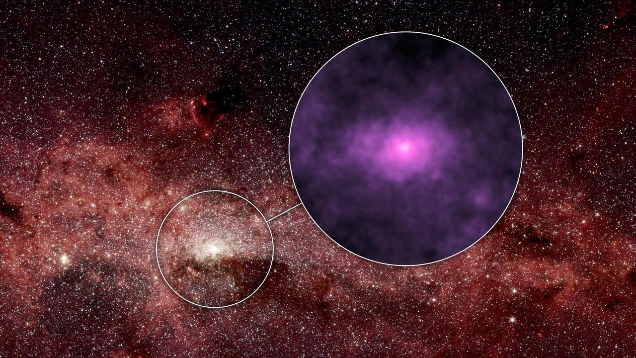
Extra X-rays at the Hub of Our Milky Way Galaxy
This most distant x-ray cluster of galaxies yet has been found by astronomers using Chandra X-ray Observatory (CXO). Approximately 10 billion light-years from Earth, the cluster 3C294 is 40 percent farther than the next most distant x-ray galaxy cluster. The existence of such a faraway cluster is important for understanding how the universe evolved. CXO's image reveals an hourglass-shaped region of x-ray emissions centered on the previously known central radio source (seen in this image as the blue central object) that extends outward for 60,000 light- years. The vast clouds of hot gas that surround such galaxies in clusters are thought to be heated by collapse toward the center of the cluster. Until CXO, x-ray telescopes have not had the needed sensitivity to identify such distant clusters of galaxies. Galaxy clusters are the largest gravitationally bound structures in the universe. The intensity of the x-rays in this CXO image of 3C294 is shown as red for low energy x-rays, green for intermediate, and blue for the most energetic x-rays. (Photo credit: NASA/loA/A. Fabian et al)
History of Chandra X-Ray Observatory
CH-47 and X-40A before Free flight 4A
Test section of the Ames 40 x 80 foot wind tunnel with the overhead doors open.  XSB2D-1 airplane being lowered onto the struts by the overhead crane. Mechanics and engineers on orchard ladders aligning the model with ball sockets on the struts. The Douglas BTD Destroyer was an American dive/ torpedo bomber developed for the United States Navy during World War II.
Installation of the Douglas XSB2D-1 in the Test Section of the 40x80 Foot Wind Tunnel at Ames.