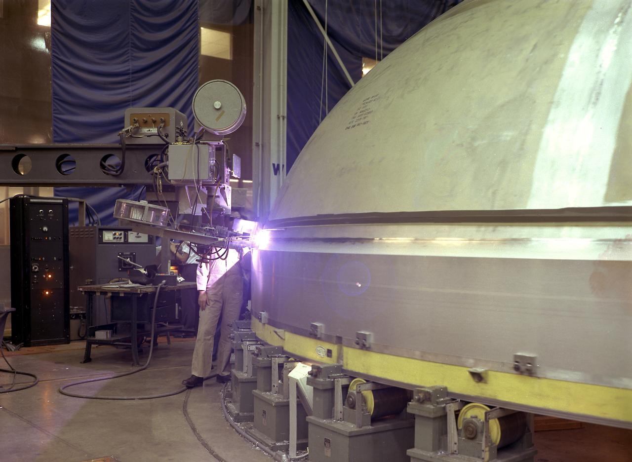
A technician is pictured at the Marshall Space Flight Center welding the Y-ring to the S-IC stage bulkhead and the fuel tank for the Saturn V SA-502 launch vehicle (Apollo 6 mission) in building 4705. The size of the S-IC required a special rig known as the Y-ring to join the tank wall cylinders and domes together. The Y-ring was designed to eliminate lap joints where the tank domes, wall, and adjoining structure (such as the intertank segment) came together.
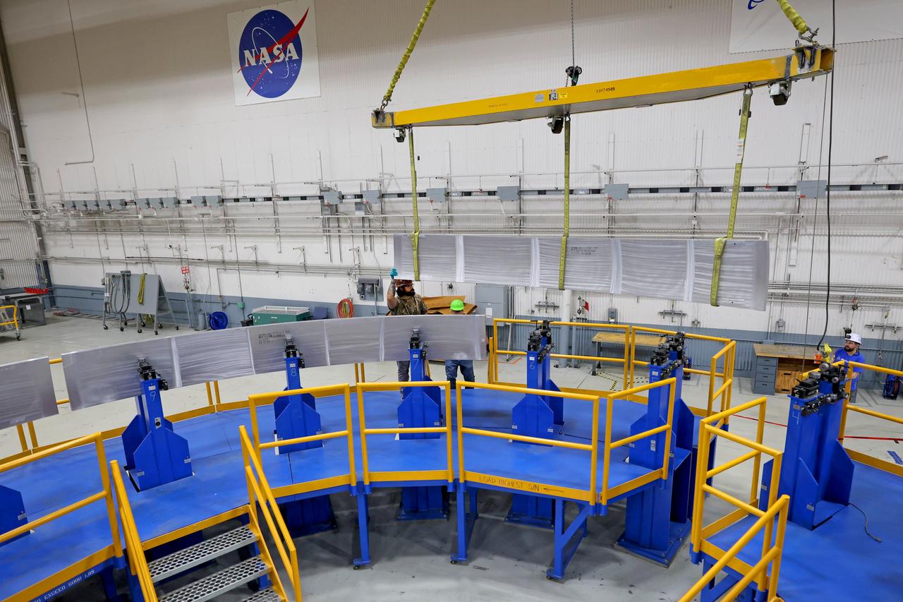
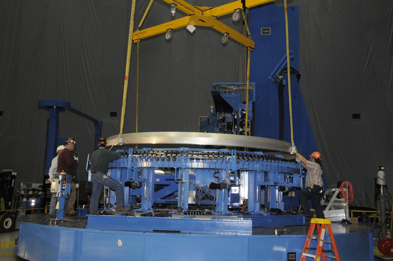
These photos show how teams at NASA’s Michoud Assembly Facility in New Orleans manufactured the Y-ring that will be used on the evolved Block 1B configuration of the SLS (Space Launch System) rocket. It is one of the first components that will make up a portion of the core stage that will power NASA’s Artemis V mission. The large metal ring will serve as the aft ring for the rocket’s liquid hydrogen tank. The SLS core stage is the backbone of the SLS rocket, stretching 212 feet from top to bottom, and includes four RS-25 engines at its base. At launch, its two huge liquid propellant tanks provide more than 733,000 gallons of fuel to produce more than 2 million pounds of thrust. Michoud Assembly Facility and the SLS Program are managed by NASA’s Marshall Space Flight Center in Huntsville, Alabama. Image credit: NASA/Michael DeMocker

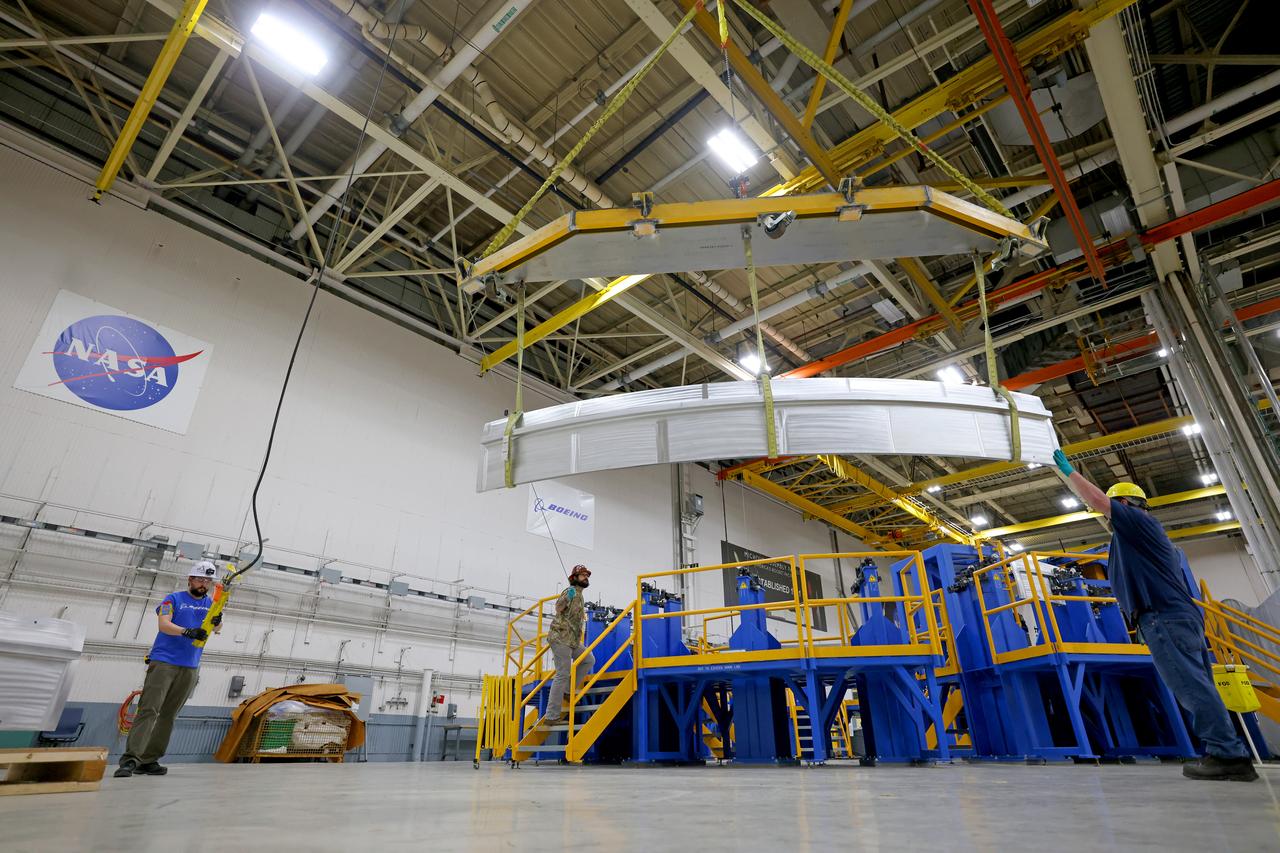
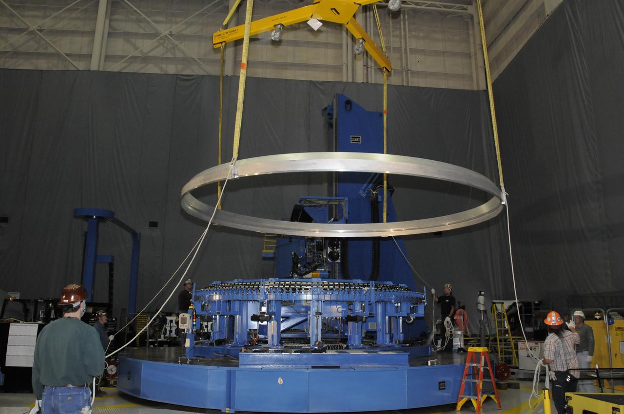
These photos show how teams at NASA’s Michoud Assembly Facility in New Orleans manufactured the Y-ring that will be used on the evolved Block 1B configuration of the SLS (Space Launch System) rocket. It is one of the first components that will make up a portion of the core stage that will power NASA’s Artemis V mission. The large metal ring will serve as the aft ring for the rocket’s liquid hydrogen tank. The SLS core stage is the backbone of the SLS rocket, stretching 212 feet from top to bottom, and includes four RS-25 engines at its base. At launch, its two huge liquid propellant tanks provide more than 733,000 gallons of fuel to produce more than 2 million pounds of thrust. Michoud Assembly Facility and the SLS Program are managed by NASA’s Marshall Space Flight Center in Huntsville, Alabama. Image credit: NASA/Michael DeMocker
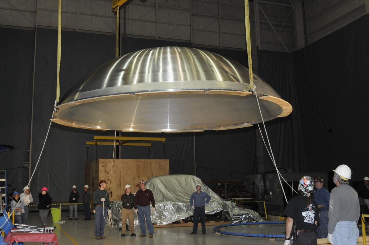
These photos show how teams at NASA’s Michoud Assembly Facility in New Orleans manufactured the Y-ring that will be used on the evolved Block 1B configuration of the SLS (Space Launch System) rocket. It is one of the first components that will make up a portion of the core stage that will power NASA’s Artemis V mission. The large metal ring will serve as the aft ring for the rocket’s liquid hydrogen tank. The SLS core stage is the backbone of the SLS rocket, stretching 212 feet from top to bottom, and includes four RS-25 engines at its base. At launch, its two huge liquid propellant tanks provide more than 733,000 gallons of fuel to produce more than 2 million pounds of thrust. Michoud Assembly Facility and the SLS Program are managed by NASA’s Marshall Space Flight Center in Huntsville, Alabama. Image credit: NASA/Michael DeMocker

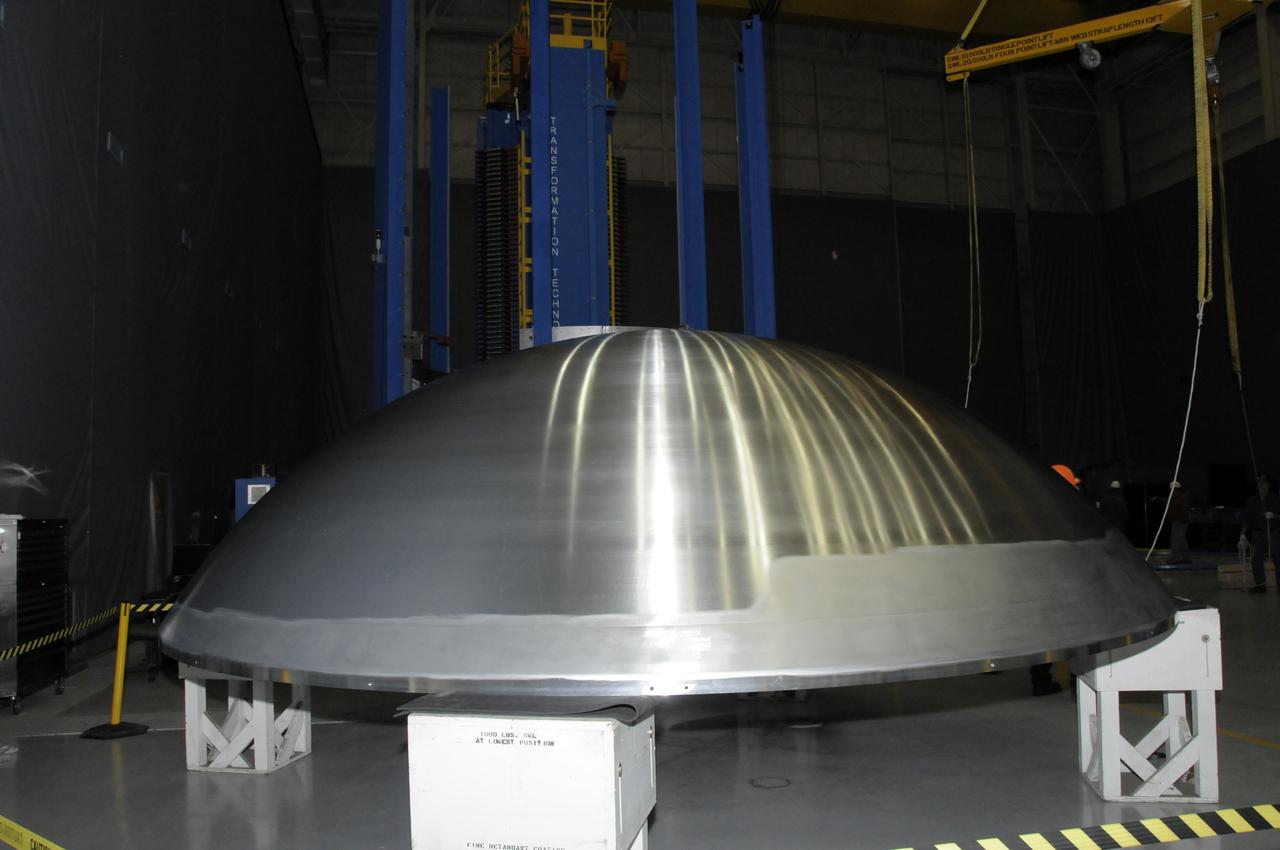
These photos show how teams at NASA’s Michoud Assembly Facility in New Orleans manufactured the Y-ring that will be used on the evolved Block 1B configuration of the SLS (Space Launch System) rocket. It is one of the first components that will make up a portion of the core stage that will power NASA’s Artemis V mission. The large metal ring will serve as the aft ring for the rocket’s liquid hydrogen tank. The SLS core stage is the backbone of the SLS rocket, stretching 212 feet from top to bottom, and includes four RS-25 engines at its base. At launch, its two huge liquid propellant tanks provide more than 733,000 gallons of fuel to produce more than 2 million pounds of thrust. Michoud Assembly Facility and the SLS Program are managed by NASA’s Marshall Space Flight Center in Huntsville, Alabama. Image credit: NASA/Michael DeMocker
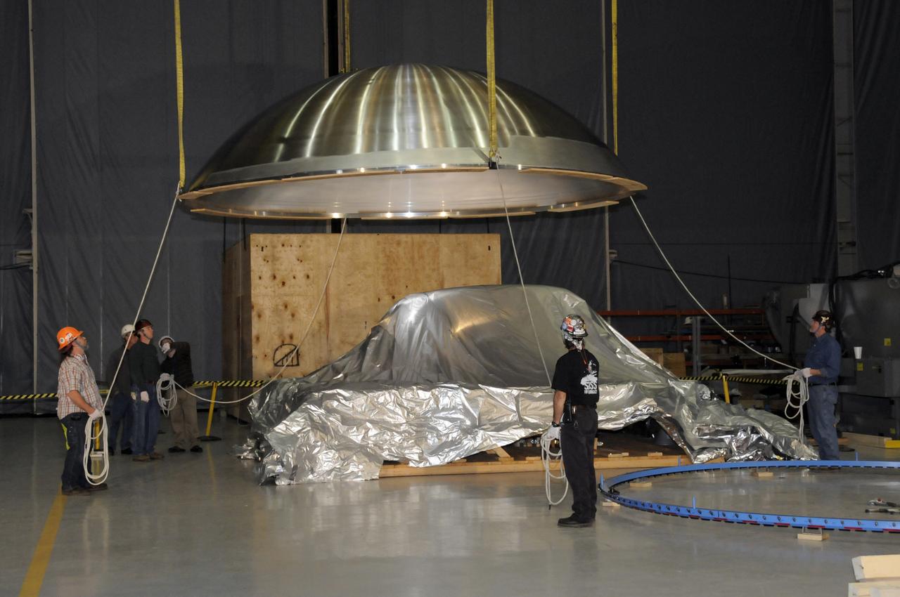
ARES HARDWARE MOVE IN BUILDING 4755 OF A Y-RING INTO THE ROBOTIC WELD TOOL & THE COMMON BULKHEAD DOME MANUFACTURING DEMONSTRATION ARTICLE ONTO THE WOODEN TOOLING STANDS ON FEBRUARY 19, 2010
ARES HARDWARE MOVE IN BUILDING 4755 OF A Y-RING INTO THE ROBOTIC WELD TOOL & THE COMMON BULKHEAD DOME MANUFACTURING DEMONSTRATION ARTICLE ONTO THE WOODEN TOOLING STANDS ON FEBRUARY 19, 2010
ARES HARDWARE MOVE IN BUILDING 4755 OF A Y-RING INTO THE ROBOTIC WELD TOOL & THE COMMON BULKHEAD DOME MANUFACTURING DEMONSTRATION ARTICLE ONTO THE WOODEN TOOLING STANDS ON FEBRUARY 19, 2010
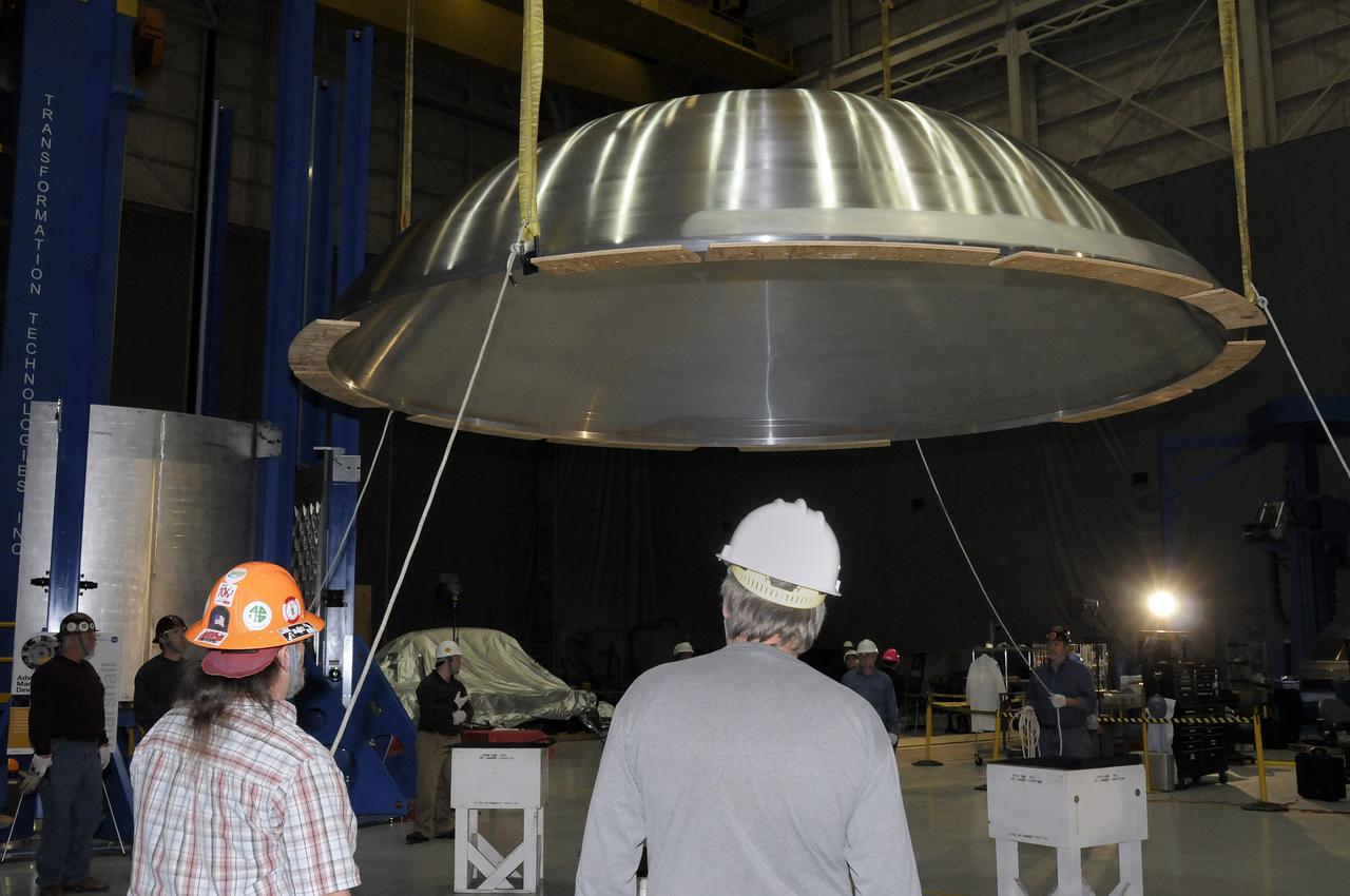
ARES HARDWARE MOVE IN BUILDING 4755 OF A Y-RING INTO THE ROBOTIC WELD TOOL & THE COMMON BULKHEAD DOME MANUFACTURING DEMONSTRATION ARTICLE ONTO THE WOODEN TOOLING STANDS ON FEBRUARY 19, 2010
ARES HARDWARE MOVE IN BUILDING 4755 OF A Y-RING INTO THE ROBOTIC WELD TOOL & THE COMMON BULKHEAD DOME MANUFACTURING DEMONSTRATION ARTICLE ONTO THE WOODEN TOOLING STANDS ON FEBRUARY 19, 2010
ARES HARDWARE MOVE IN BUILDING 4755 OF A Y-RING INTO THE ROBOTIC WELD TOOL & THE COMMON BULKHEAD DOME MANUFACTURING DEMONSTRATION ARTICLE ONTO THE WOODEN TOOLING STANDS ON FEBRUARY 19, 2010
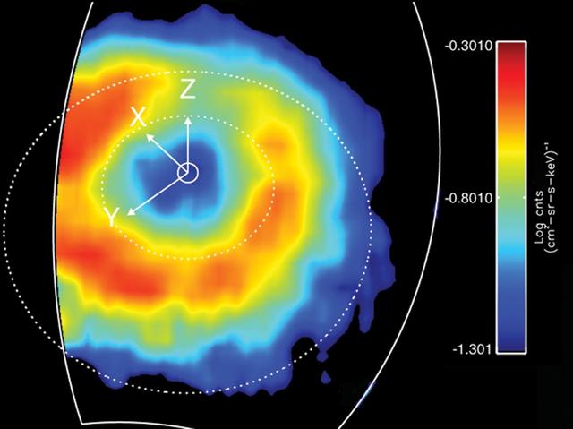
Like Earth, Saturn has an invisible ring of energetic ions trapped in its magnetic field. This feature is known as a "ring current." This ring current has been imaged with a special camera on Cassini sensitive to energetic neutral atoms. This is a false color map of the intensity of the energetic neutral atoms emitted from the ring current through a processed called charged exchange. In this process a trapped energetic ion steals and electron from cold gas atoms and becomes neutral and escapes the magnetic field. The Cassini Magnetospheric Imaging Instrument's ion and neutral camera records the intensity of the escaping particles, which provides a map of the ring current. In this image, the colors represent the intensity of the neutral emission, which is a reflection of the trapped ions. This "ring" is much farther from Saturn (roughly five times farther) than Saturn's famous icy rings. Red in the image represents the higher intensity of the particles, while blue is less intense. Saturn's ring current had not been mapped before on a global scale, only "snippets" or areas were mapped previously but not in this detail. This instrument allows scientists to produce movies (see PIA10083) that show how this ring changes over time. These movies reveal a dynamic system, which is usually not as uniform as depicted in this image. The ring current is doughnut shaped but in some instances it appears as if someone took a bite out of it. This image was obtained on March 19, 2007, at a latitude of about 54.5 degrees and radial distance 1.5 million kilometres (920,000 miles). Saturn is at the center, and the dotted circles represent the orbits of the moon's Rhea and Titan. The Z axis points parallel to Saturn's spin axis, the X axis points roughly sunward in the sun-spin axis plane, and the Y axis completes the system, pointing roughly toward dusk. The ion and neutral camera's field of view is marked by the white line and accounts for the cut-off of the image on the left. The image is an average of the activity over a (roughly) 3-hour period. http://photojournal.jpl.nasa.gov/catalog/PIA10094
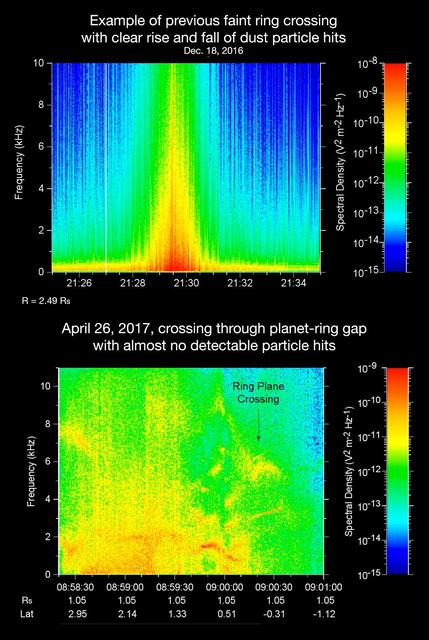
The sounds and spectrograms in these two videos represent data collected by the Radio and Plasma Wave Science, or RPWS, instrument on NASA's Cassini spacecraft, as it crossed the plane of Saturn's rings on two separate orbits. As tiny, dust-sized particles strike Cassini and the three 33-foot-long (10-meter-long), RPWS antennas, the particles are vaporized into tiny clouds of plasma, or electrically excited gas. These tiny explosions make a small electrical signal (a voltage impulse) that RPWS can detect. Researchers on the RPWS team convert the data into visible and audio formats, like those seen here, for analysis. Ring particle hits sound like pops and cracks in the audio. The first video (top image in the montage) was made using RPWS data from a ring plane crossing on Dec. 18, 2016, when the spacecraft passed through the faint, dusty Janus-Epimetheus ring (see PIA08328 for an image that features this ring). This was during Cassini's 253rd orbit of Saturn, known as Rev 253. As is typical for this sort of ring crossing, the number of audible pops and cracks rises to a maximum around the time of a ring crossing and trails off afterward. The peak of the ring density is obvious in the colored display at the red spike. The second video (bottom image in the montage) was made using data RPWS collected as Cassini made the first dive through the gap between Saturn and its rings as part of the mission's Grand Finale, on April 26, 2017. Very few pops and cracks are audible in this data at all. In comparing the two data sets, it is apparent that while Cassini detected many ring-particles striking Cassini when passing through the Janus-Epimetheus ring, the first Grand Finale crossing -- in stark contrast -- was nearly particle free. The unexpected finding that the gap is so empty is a new mystery that scientists are eager to understand. On April 26, 2017, Cassini dove through the previously unexplored ring-planet gap at speeds approaching 75,000 mph (121,000 kph), using its large, dish-shaped high-gain antenna (or HGA) as a shield to protect the rest of the spacecraft and its instruments from potential impacts by small, icy ring particles. Two of Cassini's instruments, the magnetometer and RPWS, extend beyond the protective antenna dish, and were exposed to the particle environment during the dive. The Cassini team used this data from RPWS, along with inputs from other components on the spacecraft, to make the decision of whether the HGA would be needed as a shield on most future Grand Finale dives through the planet-ring gap. Based on these inputs the team determined this protective measure would not be needed, allowing the team's preferred mode of science operations to proceed, with Cassini able to point its science instruments in any direction necessary to obtain scientists' desired observations. (Four of the 21 remaining dives pass through the inner D ring. The mission had already planned to use the HGA as a shield for those passes.) The colors on the spectrogram indicate the emitted power of the radio waves, with red as the most powerful. Time is on the x-axis, and frequency of the radio waves is on the y-axis. The audible whistle in the April 26 data, just before ring plane crossing, is due to a type of plasma wave that will be the subject of further study. In addition, there is an abrupt change beginning at the 09:00:00 mark on the spectrogram that represents a change in the RPWS antenna's operational configuration (from monopole mode to dipole mode). The videos can be viewed at https://photojournal.jpl.nasa.gov/catalog/PIA21446