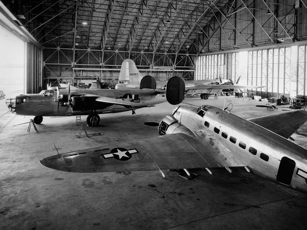
A Consolidated B–24D Liberator (left), Boeing B–29 Superfortress (background), and Lockheed RA–29 Hudson (foreground) parked inside the Flight Research Building at the National Advisory Committee for Aeronautics (NACA) Aircraft Engine Research Laboratory in Cleveland, Ohio. A P–47G Thunderbolt and P–63A King Cobra are visible in the background. The laboratory utilized 15 different aircraft during the final 2.5 years of World War II. This starkly contrasts with the limited-quantity, but long-duration aircraft of the NASA’s modern fleet. The Flight Research Building is a 272- by 150-foot hangar with an internal height ranging from 40 feet at the sides to 90 feet at its apex. The steel support trusses were pin-connected at the top with tension members extending along the corrugated transite walls down to the floor. The 37.5-foot-tall and 250-foot-long doors on either side can be opened in sections. The hangar included a shop area and stock room along the far wall, and a single-story office wing with nine offices, behind the camera. The offices were later expanded. The hangar has been in continual use since its completion in December 1942. Nearly 70 different aircraft have been sheltered here over the years. Temporary offices were twice constructed over half of the floor area when office space was at a premium.
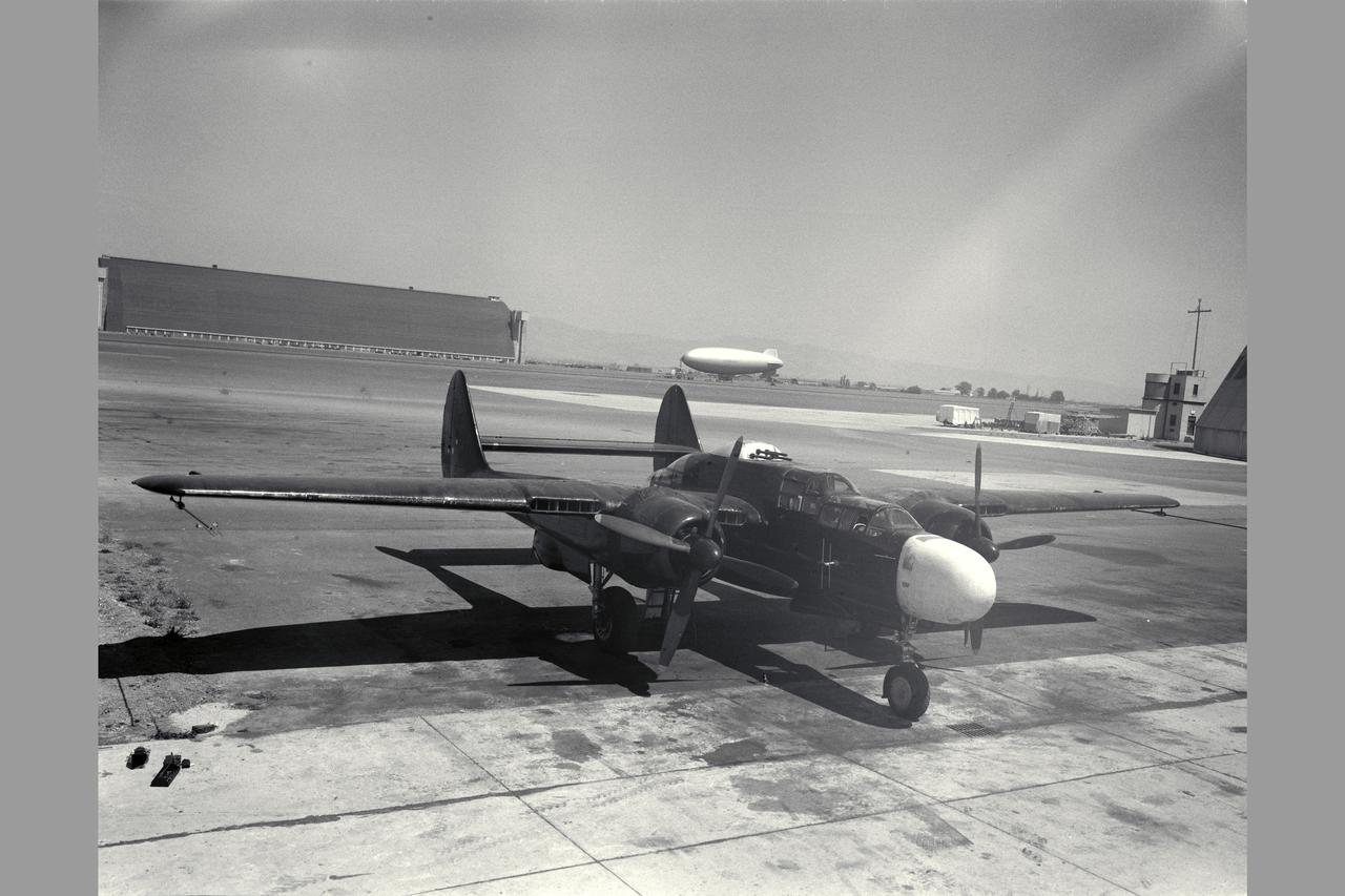
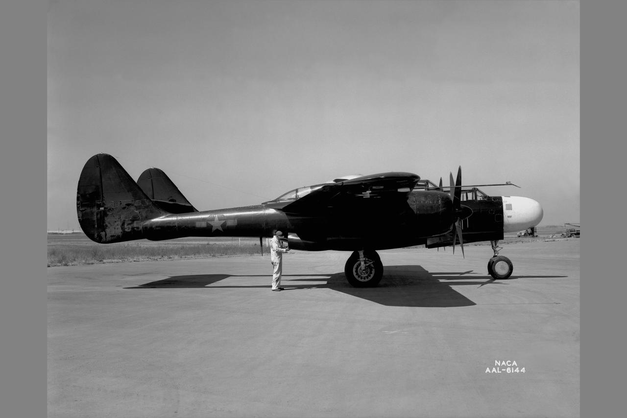
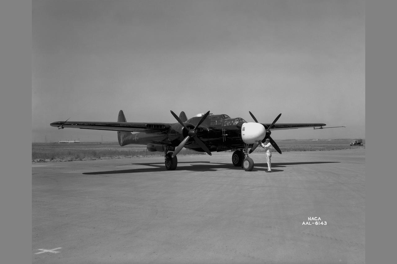
Northrop P-61A-5 Black Widow (AAF42-5572) Note: Used in publication in Flight Research at Ames; 57 Years of Development and Validation of Aeronautical Technology NASA SP-1998-3300 fig 44
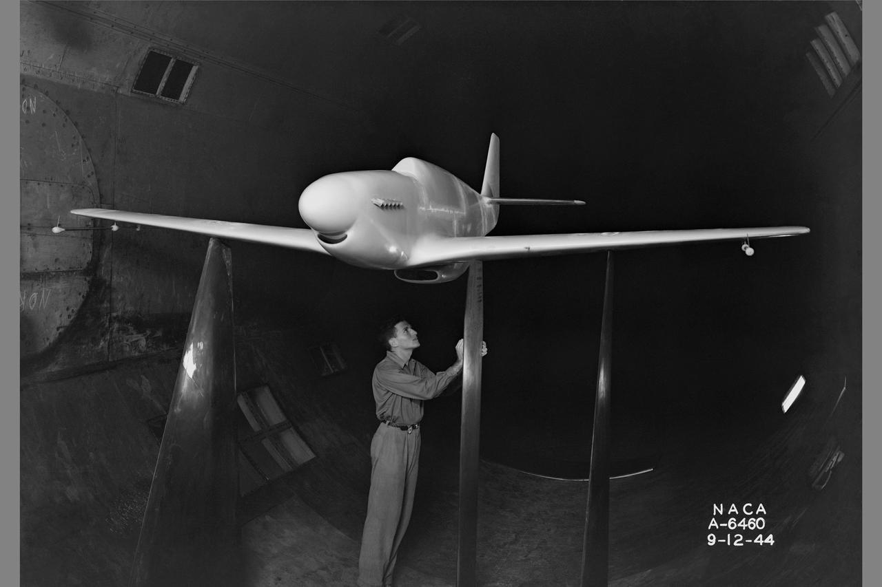
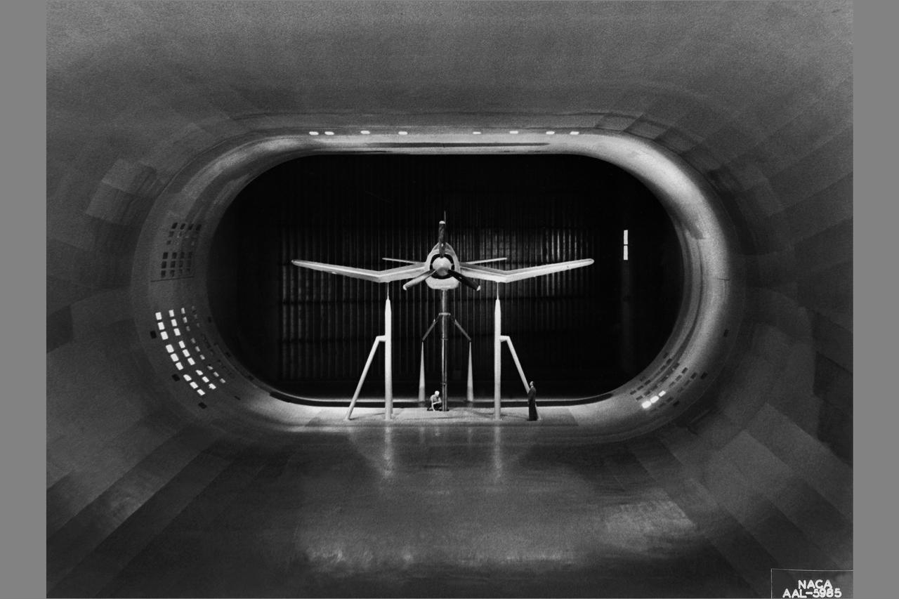
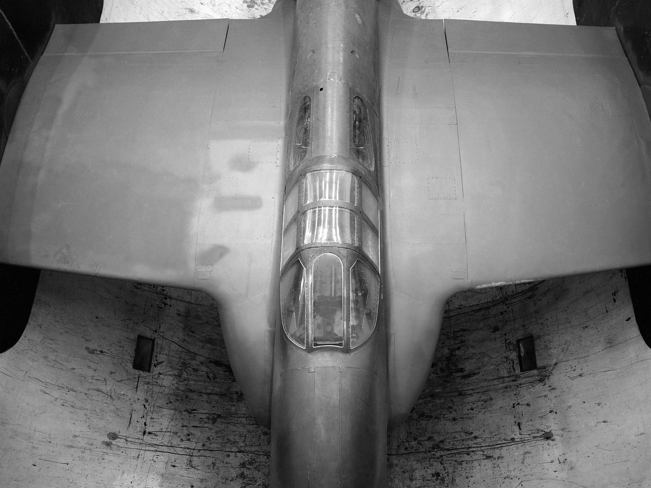
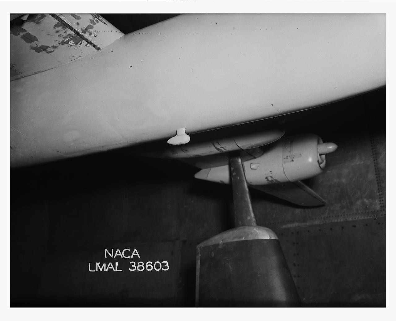
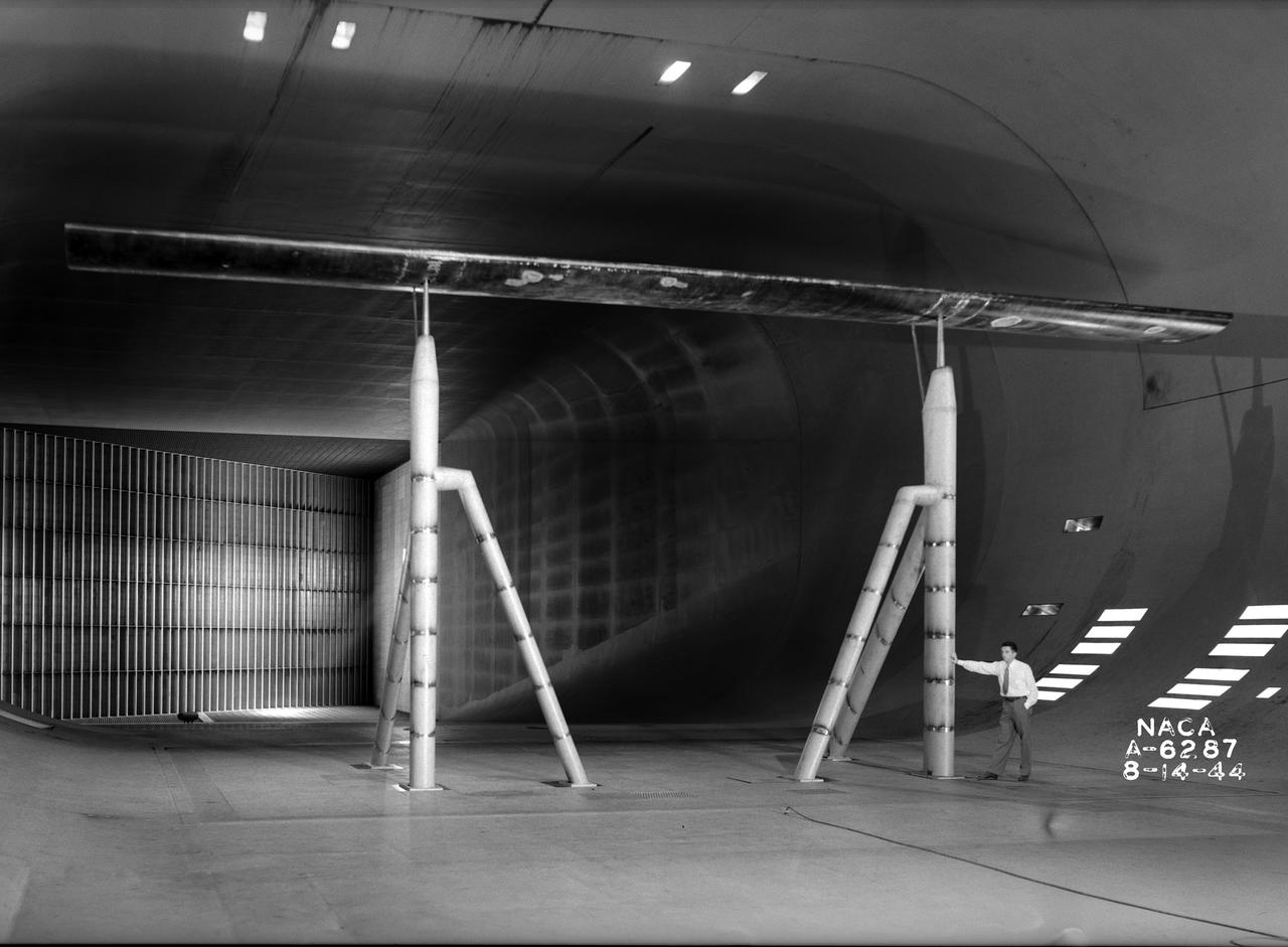
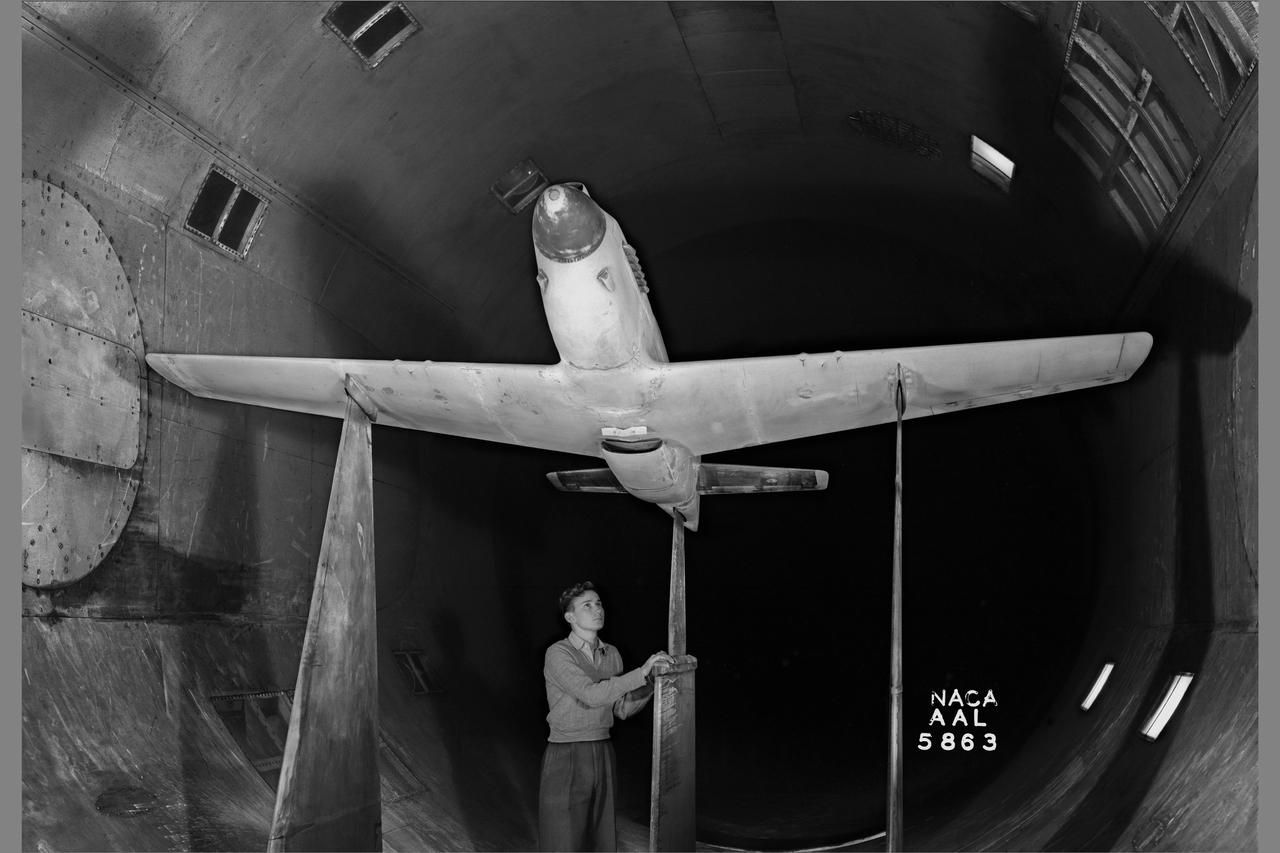
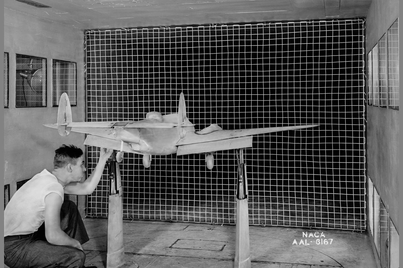
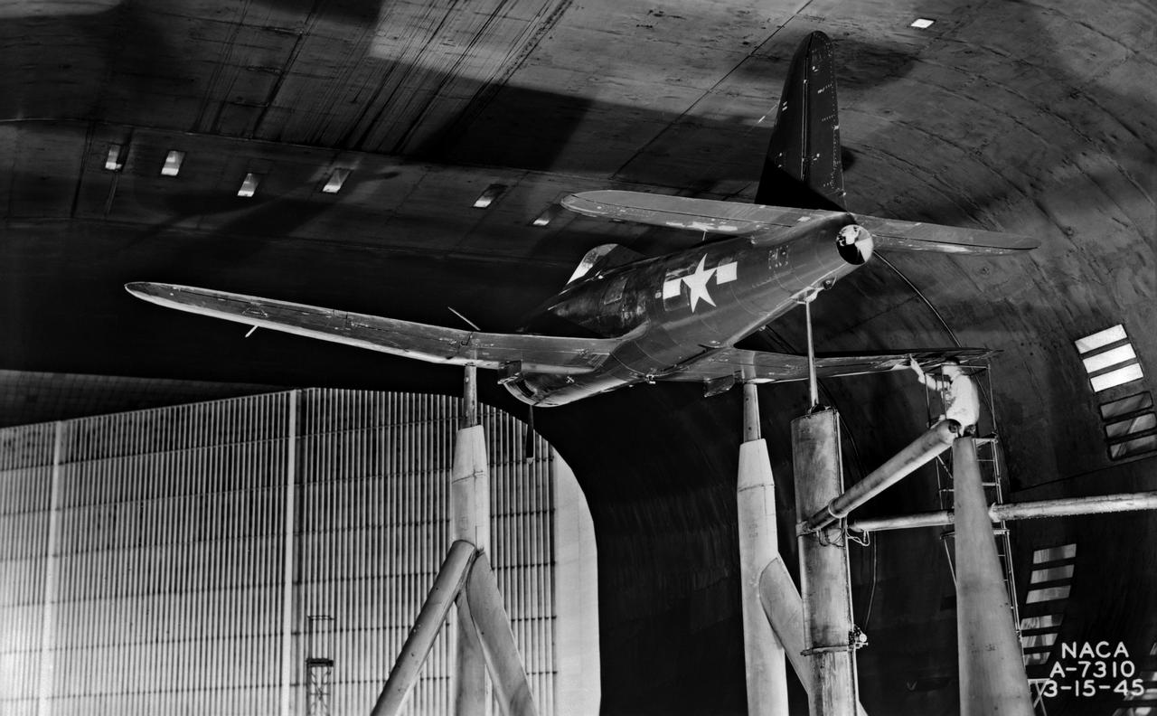
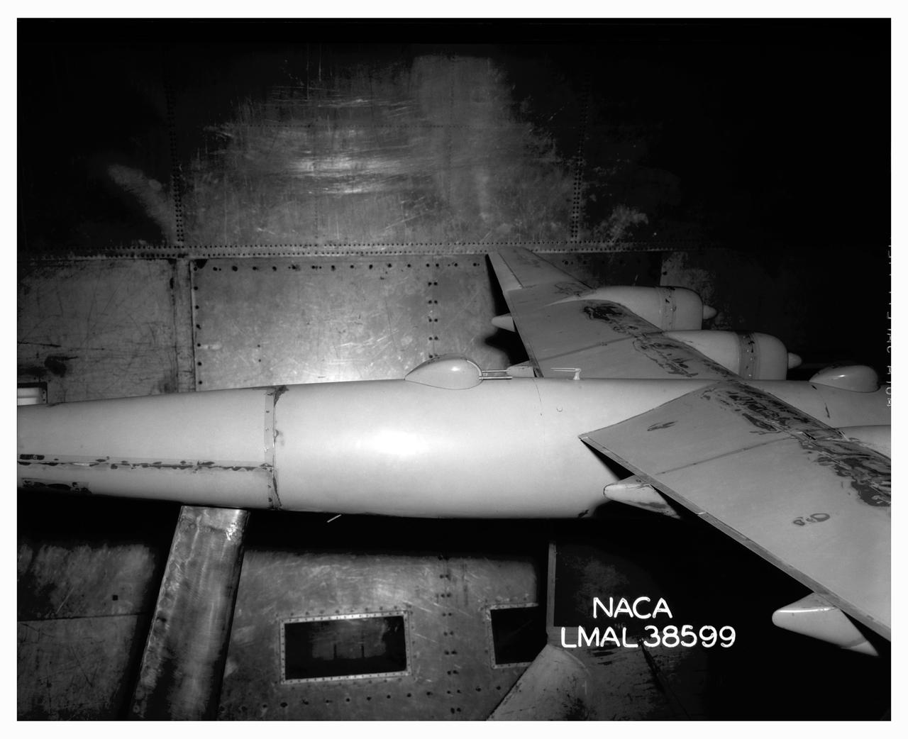
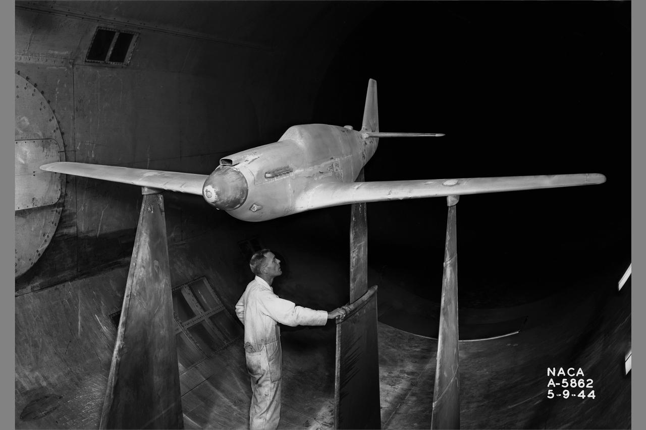
North American P-51B 1/3 scale model with dummy airspeed booms & mounted on thin struts in 16ft w.t.
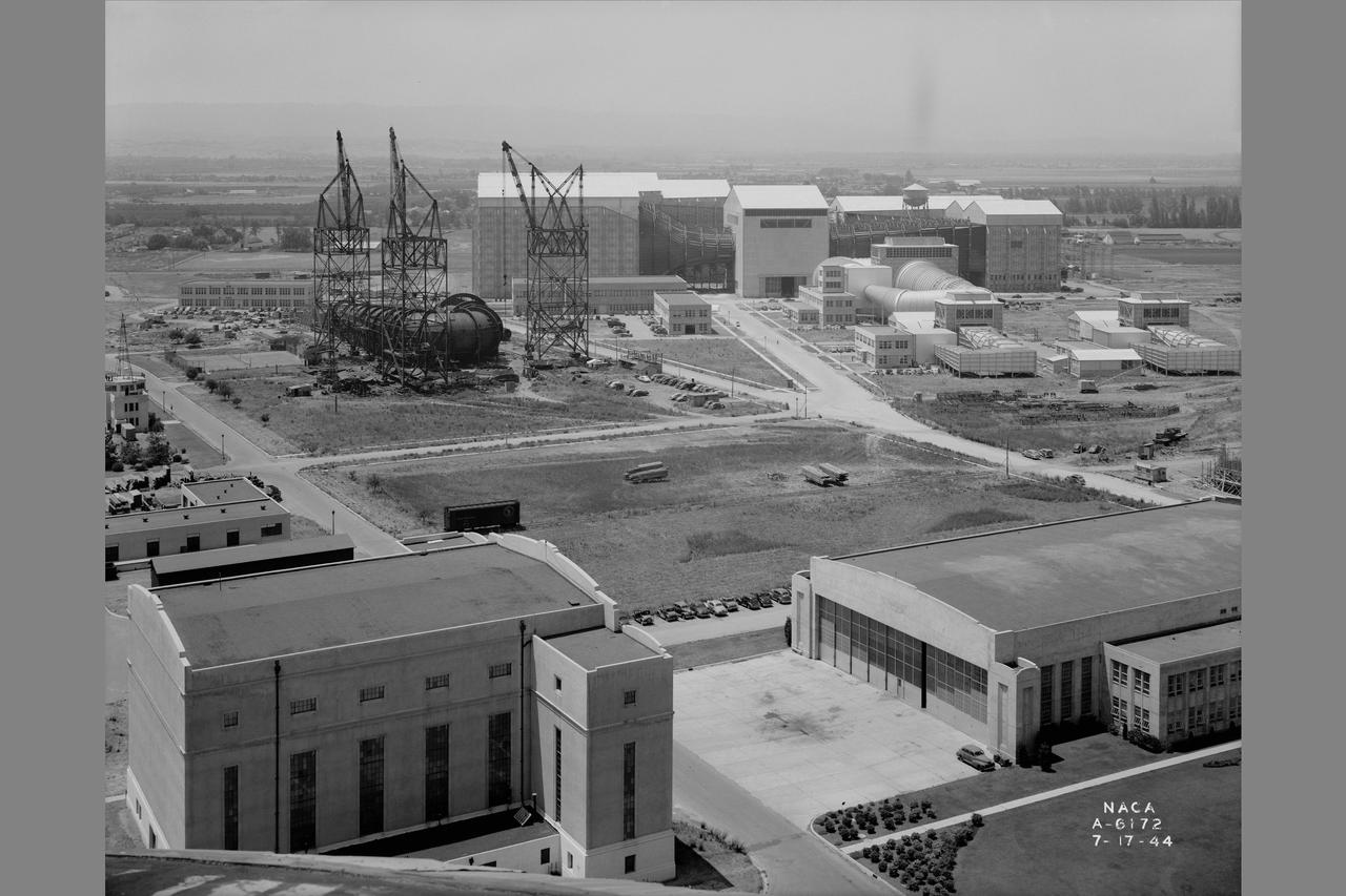
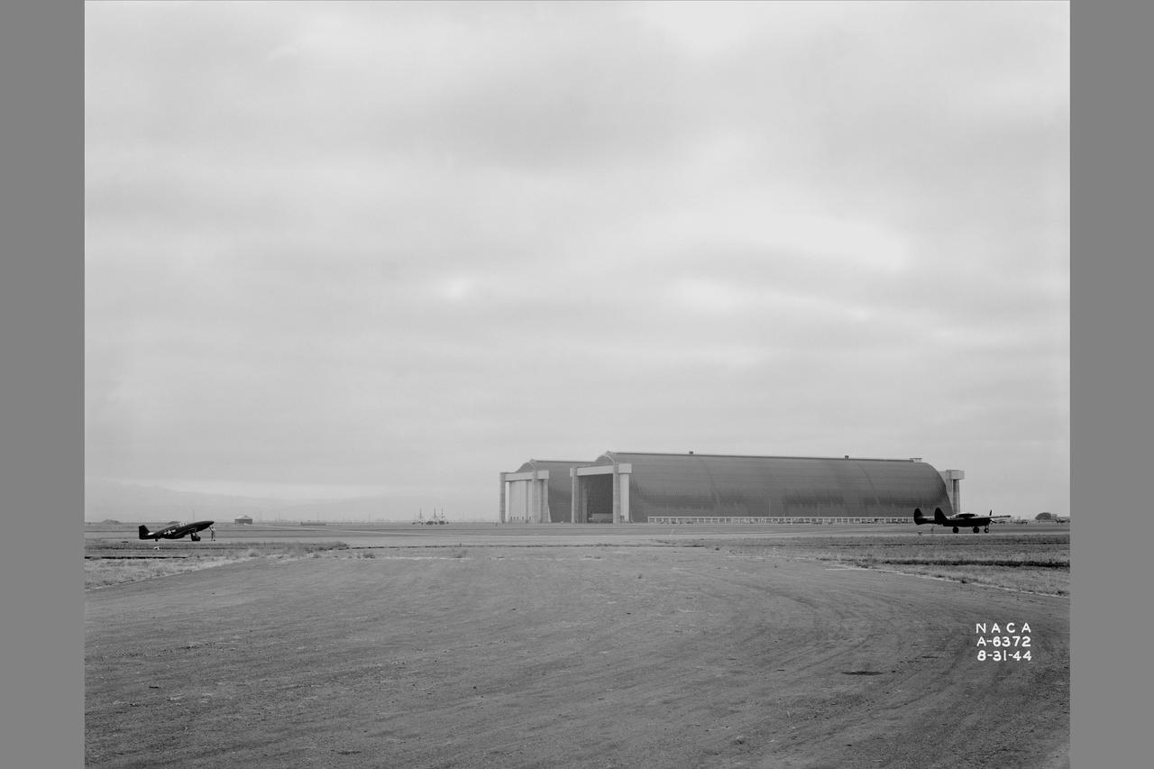
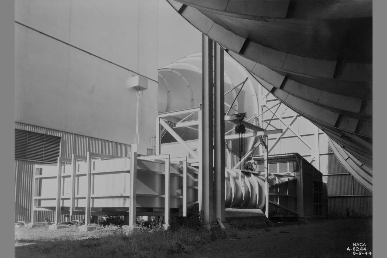
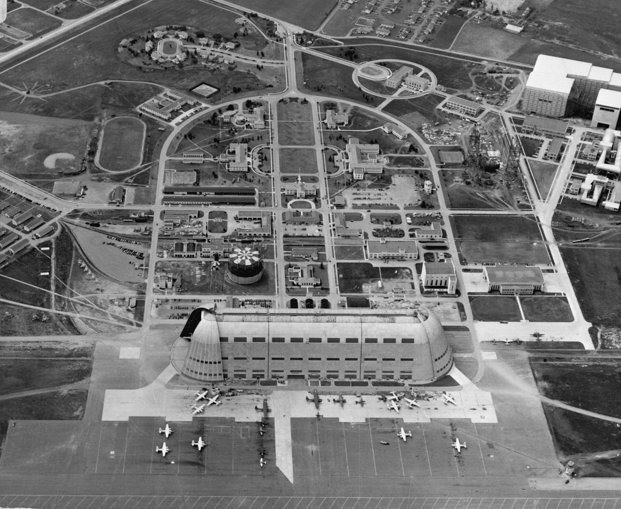
General view of Ames Aeronautical Laboratory taken from Naval airship hangar. Shows construction of the 12ft Pressure Wind Tunnel with large cranes.
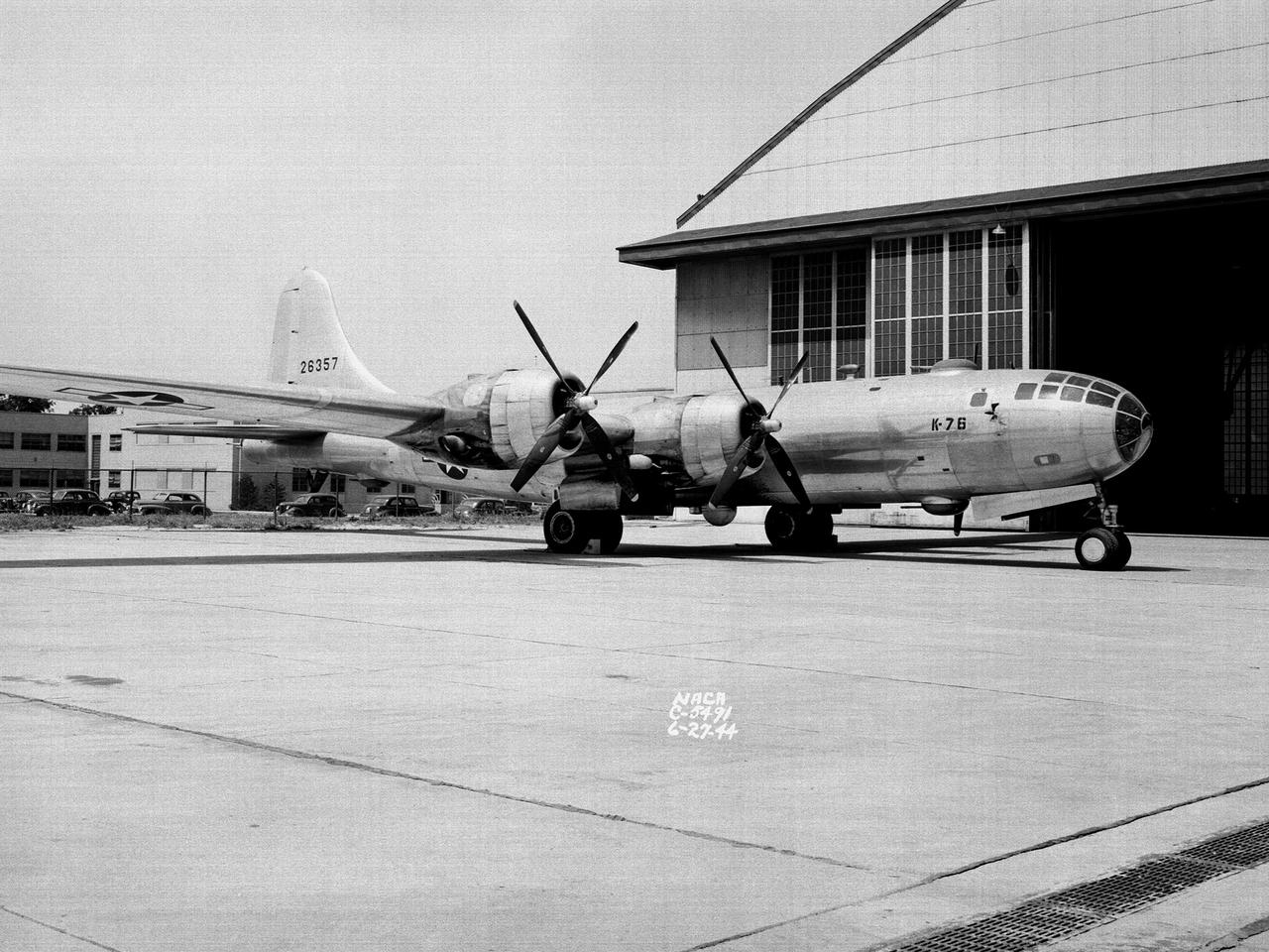
A Boeing B–29 Superfortress at the National Advisory Committee for Aeronautics (NACA) Aircraft Engine Research Laboratory in Cleveland, Ohio. The B–29 was the Army Air Forces’ deadliest weapon during the latter portion of World War II. The aircraft was significantly larger than previous bombers but could fly faster and higher. The B–29 was intended to soar above anti-aircraft fire and make pinpoint drops onto strategic targets. The bomber was forced to carry 20,000 pounds more armament than it was designed for. The extra weight pushed the B–29’s four powerful Wright R–3350 engines to their operating limits. The over-heating of the engines proved to be a dangerous problem. The military asked the NACA to tackle the issue. Full-scale engine tests on a R–3350 engine in the Prop House demonstrated that a NACA-designed impeller increased the flow rate of the fuel injection system. Altitude Wind Tunnel studies of the engine led to the reshaping of cowling inlet and outlet to improve airflow and reduce drag. Single-cylinder studies on valve failures were resolved by a slight extension of the cylinder head, and the Engine Research Building researchers combated uneven heating with a new fuel injection system. The modifications were then tried out on an actual B–29. The bomber arrived in Cleveland on June 22, 1944. The new injection impeller, ducted head baffles and instrumentation were installed on the bomber’s two left wing engines. Eleven test flights were flown over the next month with military pilots at the helm. Overall the flight tests corroborated the wind tunnel and test stand studies.
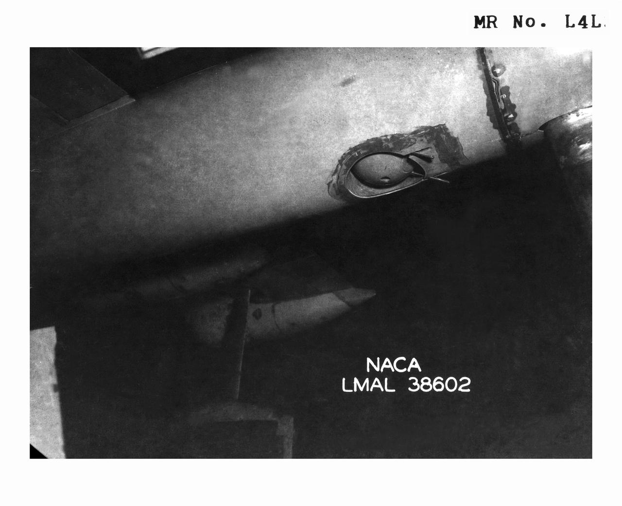
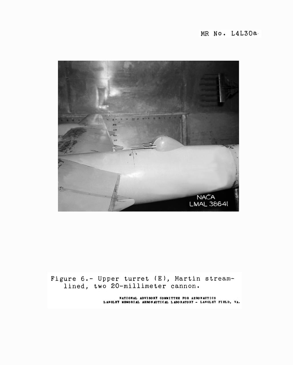
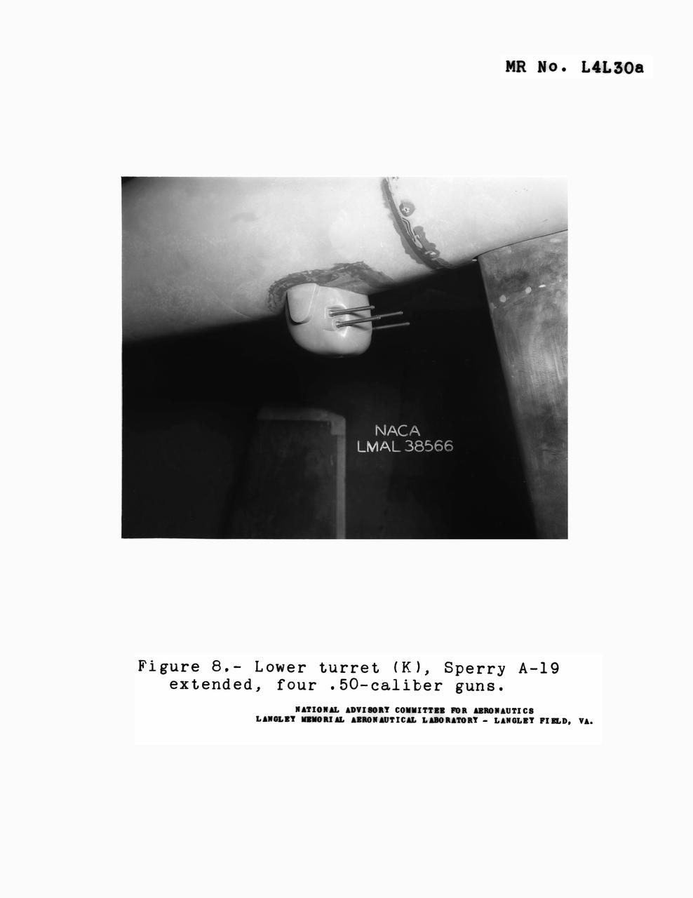
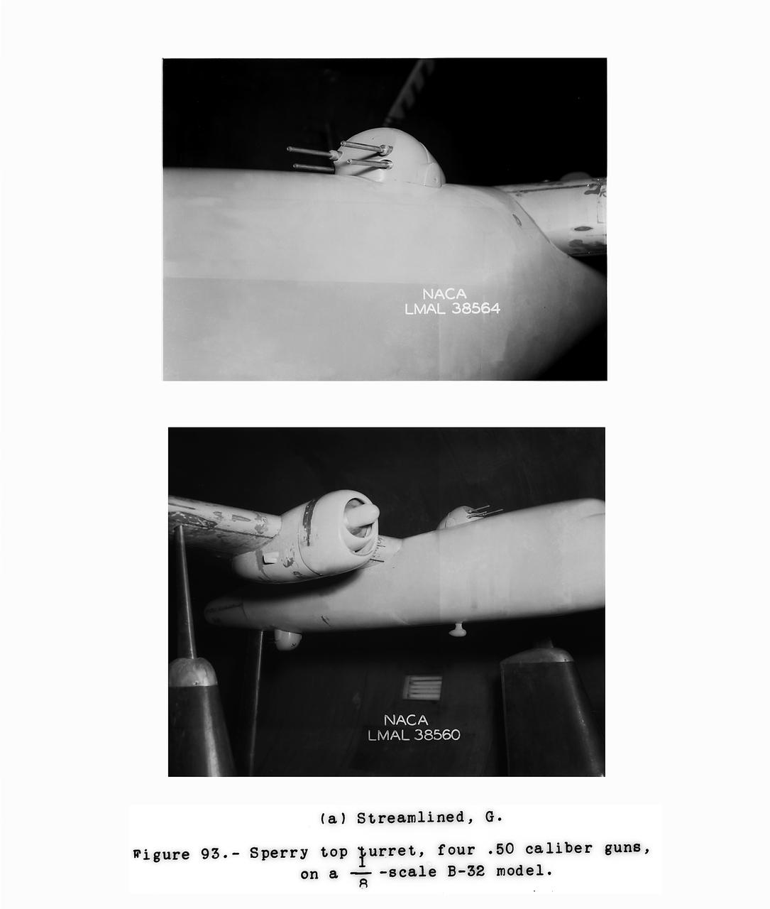
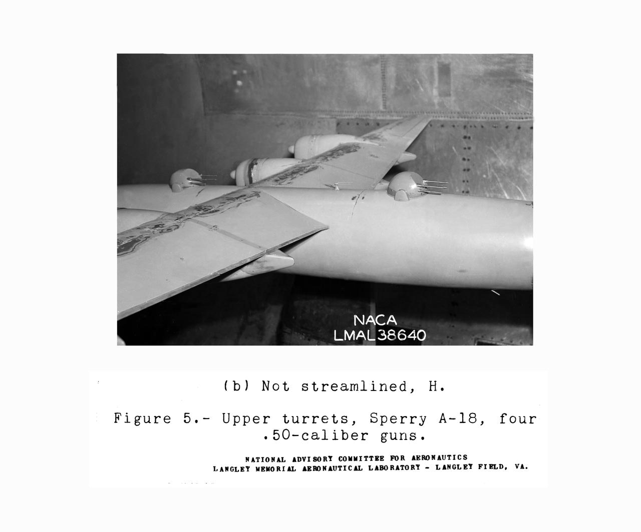
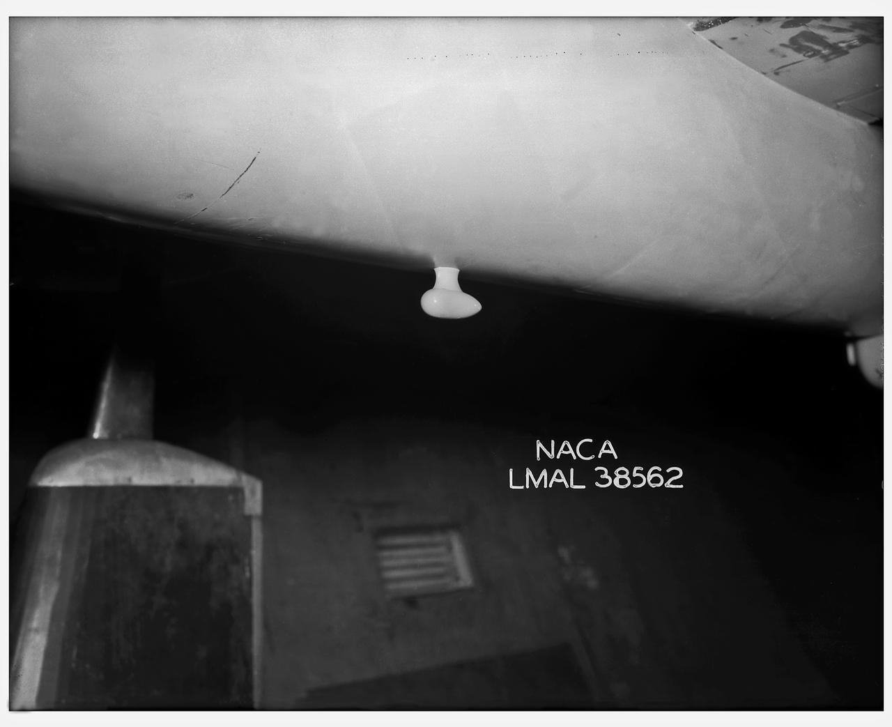
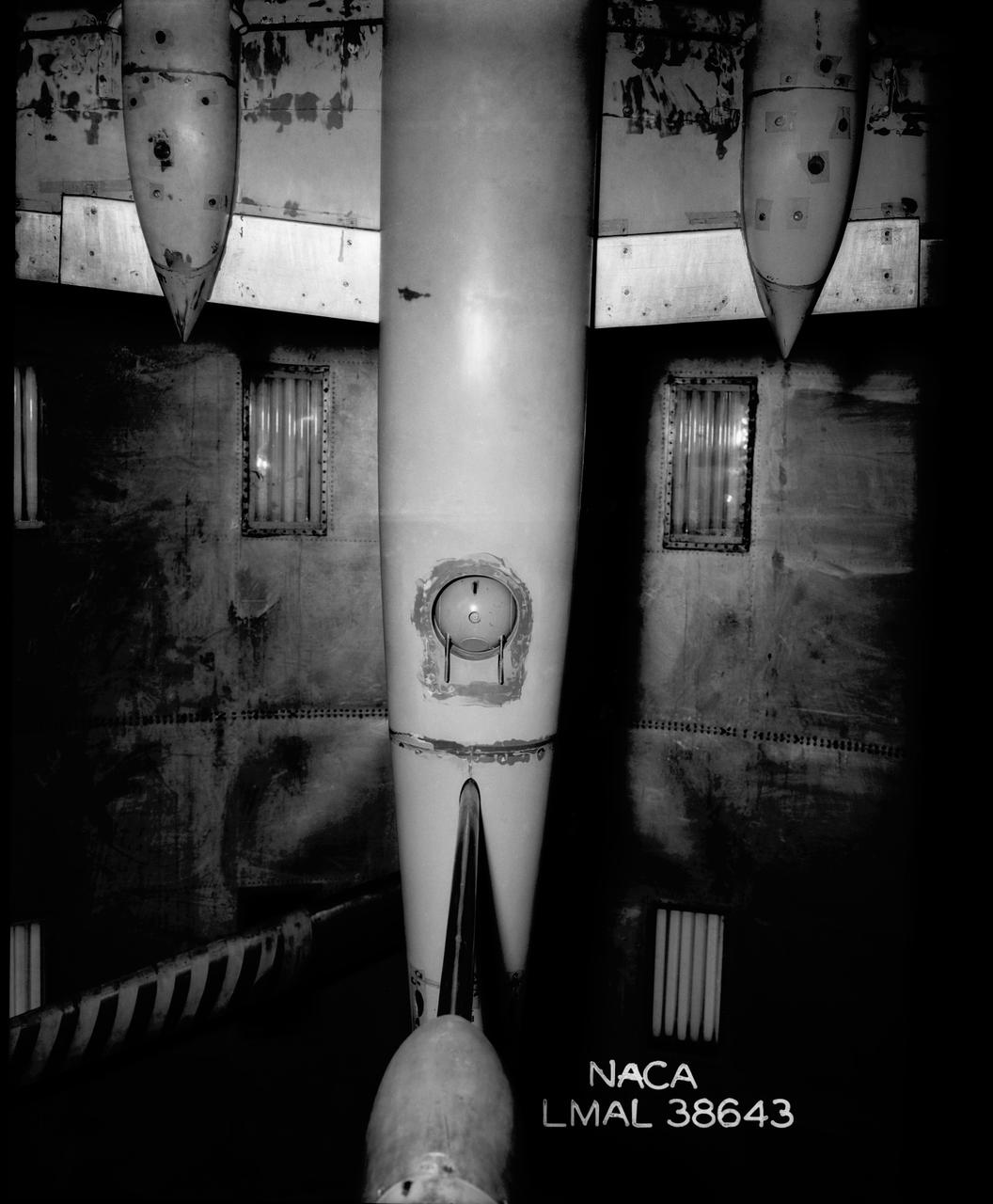
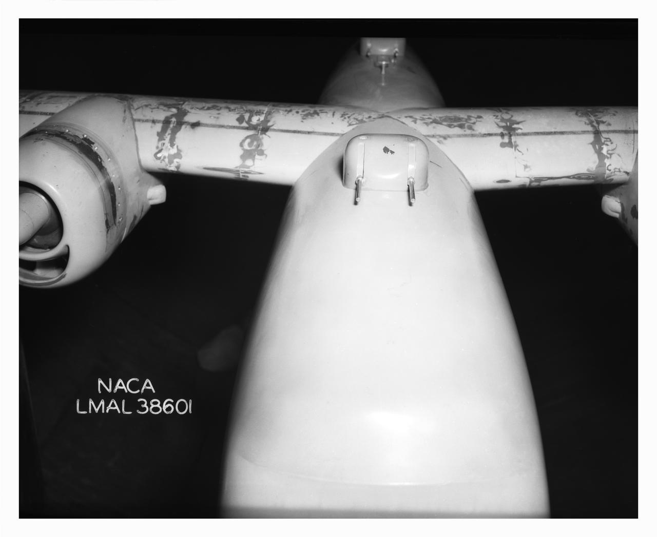
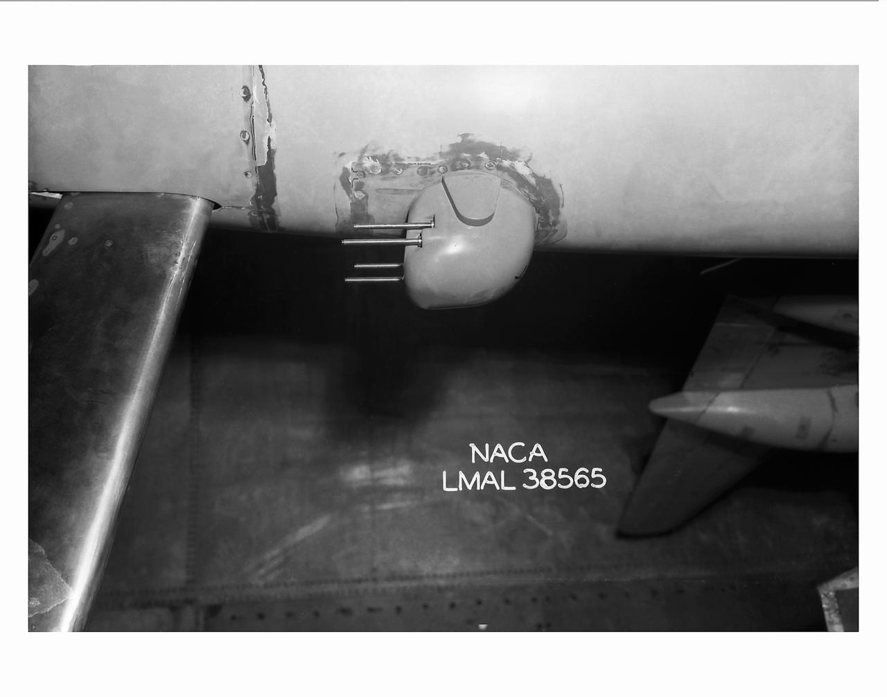
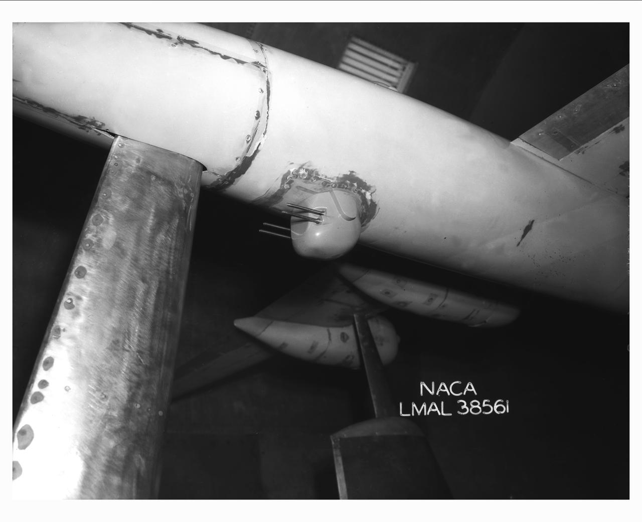
Detail Shots of B-32 Turret. B-33 Vega Turrets. Test conducted in the NACA 19 foot pressure tunnel LMAL-38560 NACA document.
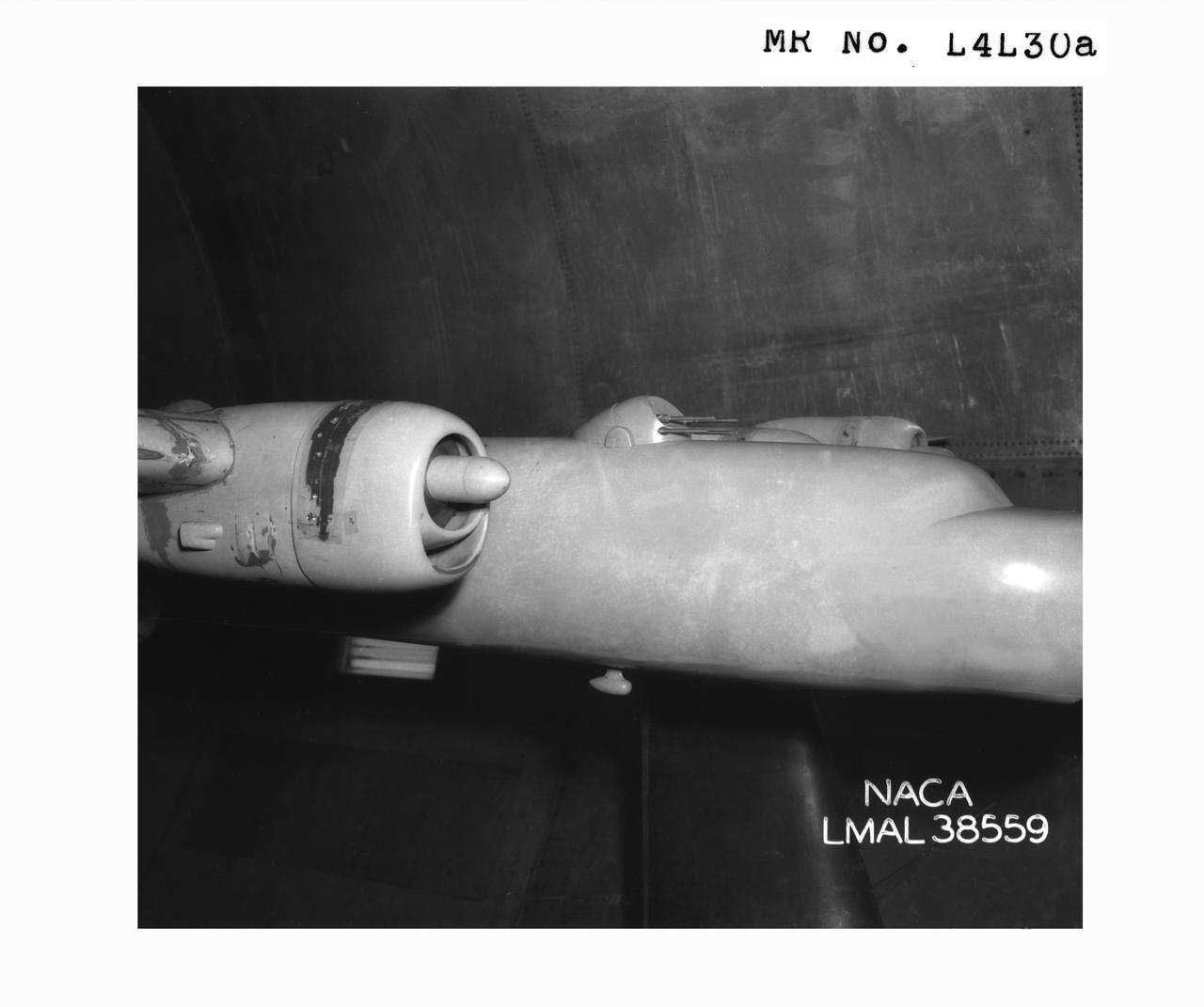
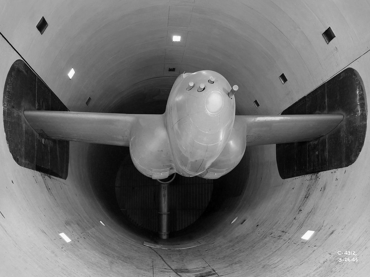
B-32 Model Close Up. Test conducted in the NACA 19 foot pressure tunnel LMAL-38560 NACA document.
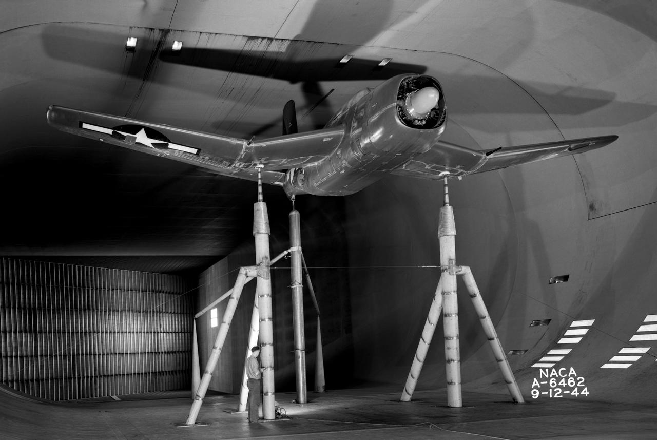
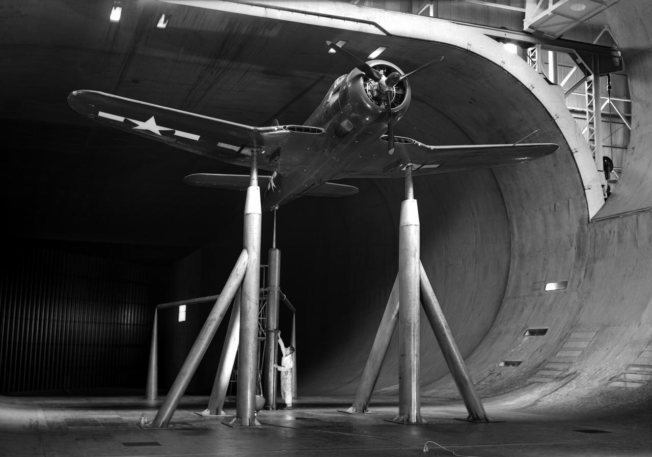
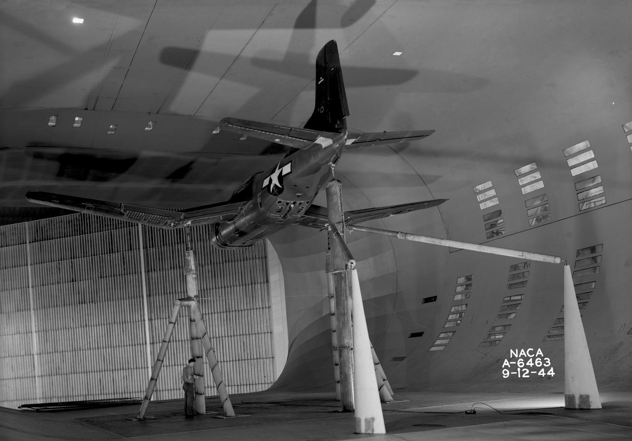
NACA Photographer XSB2D-1 Navy/Douglas Airplane mounted in 40x80ft .w.t. viewed from centerpoint in guide vanes. First model tested in 40x80ft w.t.
Gun Turrets of XP-35. Test conducted in the NACA 19 foot pressure tunnel LMAL-38560 NACA document.
Gun turrets of XP-35. Test conducted in the NACA 19 foot pressure tunnel LMAL-38560 NACA document.
B-32 Model Close Up, Test conducted in the NACA 19 foot pressure tunnel LMAL-38560 NACA document.
The Altitude Wind Tunnel (AWT) was the National Advisory Committee for Aeronautics (NACA) Aircraft Engine Research Laboratory’s largest and most important test facility in the 1940s. The AWT employed massive cooling and exhaust systems to simulate conditions found at high altitudes. The facility was originally designed to test large piston engines in a simulated flight environment. The introduction of the turbojet during the tunnel’s construction, however, changed the facility’s focus before it became operational. Its first test program was a study of the Bell YP–59A Airacomet and its General Electric I–16 turbojets. The Airacomet was the United States’ first attempt to build a jet aircraft. 1600-horsepower centrifugal engines based on an early design by British engineer Frank Whittle were incorporated into an existing Bell airframe. In October 1942 the Airacomet was secretly test flown in the California desert. The aircraft’s performance was limited, however, and the NACA was asked to study the engines in the AWT. The wind tunnel’s 20-foot-diameter test section was large enough to accommodate entire aircraft with its wing tips and tail removed. The I-16 engines were studied exhaustively in early 1944. They first analyzed the engines in their original configuration and then implemented a boundary layer removal duct, a new nacelle inlet, and new cooling seals. Tests of the modified version showed that the improved distribution of airflow increased the I–16’s performance by 25 percent. The Airacomet never overcame some of its inherent design issues, but the AWT went on to study nearly every emerging US turbojet model during the next decade.
The secret test of the Bell YP–59A Airacomet in the spring of 1944 was the first investigation in the National Advisory Committee for Aeronautics (NACA) Aircraft Engine Research Laboratory’s new Altitude Wind Tunnel (AWT). The Airacomet, powered by two General Electric I–A centrifugal turbojets, was the first US jet aircraft. The Airacomet’s 290-miles per hour speed, however, was dwarfed by the German Messerschmitt Me-262 Schwalbe’s 540 miles per hour. In 1941 and 1942 General Electric built the first US jet engines based on technical drawings from British engineer Frank Whittle. Bell Aircraft was contracted to produce an airframe to incorporate the new engines. The result was the Bell XP–59A Airacomet. The aircraft made its first flight over Muroc Lake, California, on October 2, 1942. The aircraft continued to struggle over the next year and the NACA was asked to test it in the new AWT. A Bell YP–59A was flown from the Bell plant in Buffalo to Cleveland by Bob Stanley, who had piloted the first successful flight of the XP–59A at Muroc in 1942. The wing tips and tail were cut from the aircraft so that it would fit into the AWT’s test section. The study first analyzed the engines in their original configuration and then implemented a boundary layer removal duct, a new nacelle inlet, and new cooling seals. Tests of the modified version showed that the improved airflow distribution increased the I–16’s performance by 25 percent. Despite the improved speed, the aircraft was not stable enough to be used in combat, and the design was soon abandoned.
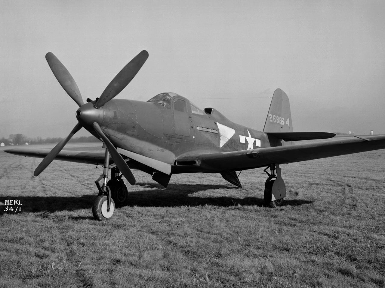
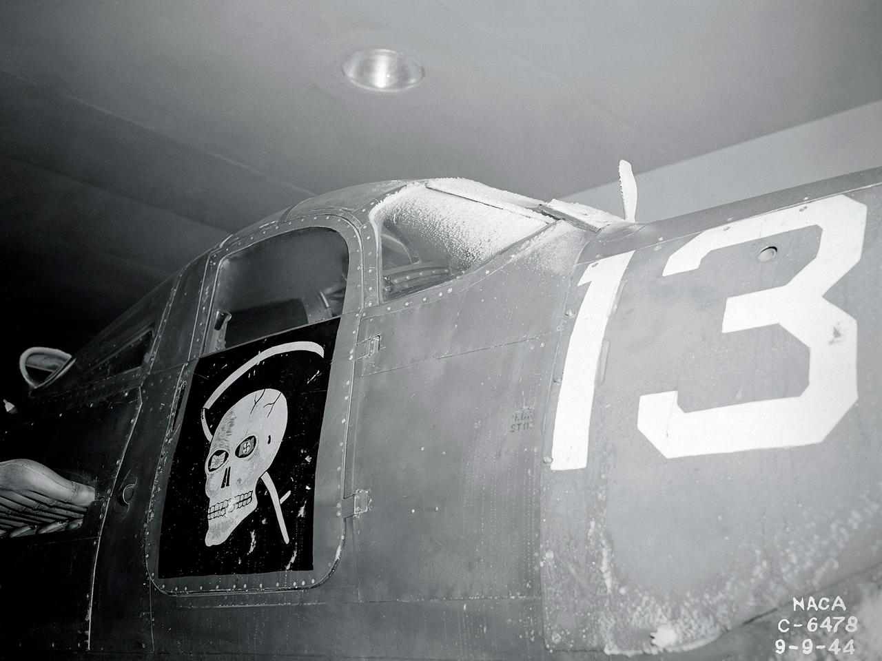
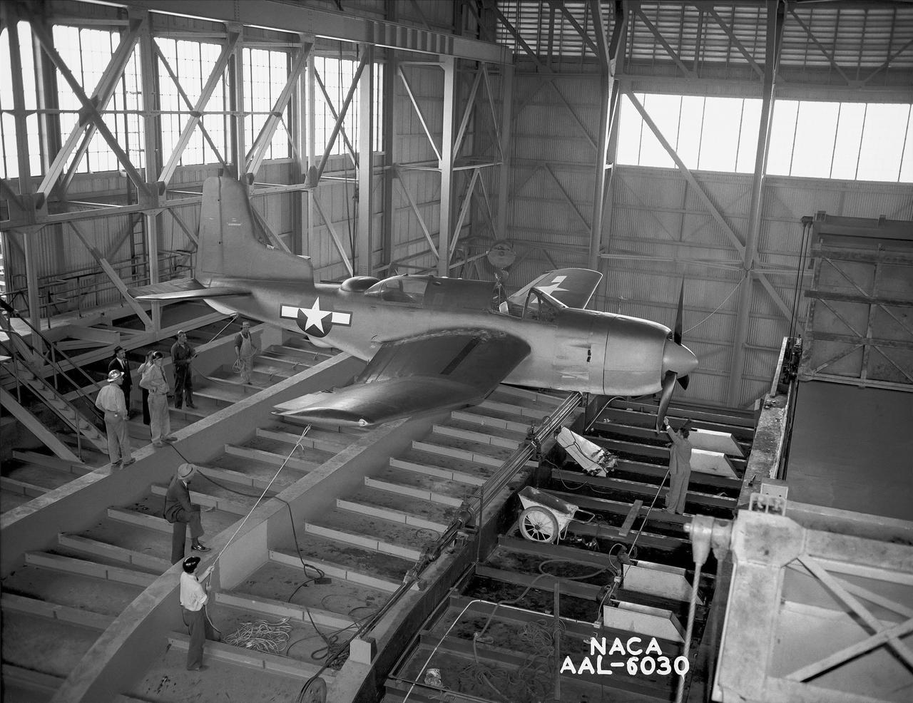
The Army Air Forces lent the National Advisory Committee for Aeronautics (NACA) Aircraft Engine Research Laboratory a Bell P–63A King Cobra in October 1943 to complement the lab's extensive efforts to improve the Allison V–1710 engine. The V–1710-powered P–63A was a single-seat fighter that could reach speeds of 410 miles per hour and an altitude of 43,000 feet. The fighter, first produced in 1942, was an improvement on Bell’s P–39, but persistent performance problems at high altitudes prevented its acceptance by the Air Corps. Instead many of the P–63s were transferred to the Soviet Union. Almost every test facility at the NACA’s engine lab was used to study the Allison V–1710 engine and its supercharger during World War II. Researchers were able to improve the efficiency, capacity and pressure ratio of the supercharger. They found that improved cooling significantly reduced engine knock in the fuel. Once the researchers were satisfied with their improvements, the new supercharger and cooling components were installed on the P–63A. The Flight Research Division first established the aircraft’s normal flight performance parameters such as speed at various altitudes, rate of climb, and peak altitude. Ensuing flights established the performance parameters of the new configuration in order to determine the improved performance. The program increased V–1710’s horsepower from 1650 to 2250.
Douglas BTD-1 airplane 3/4 front view from below in Ames 40x80 foot Wind Tunnel, unseated, horizontal tail on.
3/4 front view from below of the Ryan FR-1 airplane mounted in the NACA Ames 40x80 foot wind tunnel. Production configuration.
The Westinghouse 19XB turbojet seen from the side in the Altitude Wind Tunnel (AWT) test section at the National Advisory Committee for Aeronautics (NACA) Aircraft Engine Research Laboratory. Westinghouse started the development of a series of relatively small axial-flow turbojets for the Navy shortly after Pearl Harbor. In 1943 the 19A engine became both the first operational US-designed jet engine and the only U.S. turbojet incorporated into an aircraft during the war in Europe. In March 1943 Westinghouse agreed to create an improved six-stage 1400-pound thrust version, the 19B. The engine underwent its first test run a year later in March 1944. Almost immediately the navy agreed to Westinghouse’s proposal for the even larger 10-stage, 1600-pound-thrust 19XB prototype. By July 1944 the navy had contracted with the NACA for the testing of both engines in the AWT. The tunnel was the nation’s only facility for studying full-scale engines in simulated altitude conditions. The wind tunnel investigations, which began on September 9, 1944, revealed the superiority of the previously untested 19XB over the 19B. The 19B engines failed to restart consistently and suffered combustion blowouts above 17,000 feet. The 19XB, however, performed well and restarted routinely at twice that altitude. Two months later on January 26, 1945, two 19Bs powered a McDonnell XFD–1 Phantom, the US Navy’s first fighter jet, on its initial flight. Following its exceptional performance in the AWT, the 19XB engines soon replaced the 19Bs in the Phantom.

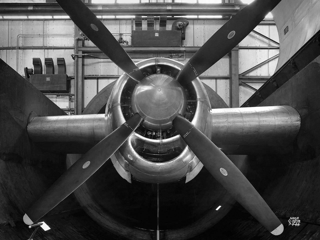
Motor and propeller blades in 40x80ft wind tunnel. Six 40-foot-diameter fans, each powered by a 6000-horsepower electric motor maintained airflow at 230 mph or less (these are still tornado velocities).
B-32 Model Close Up. Test conducted in the NACA 19 foot pressure tunnel LMAL-38560 NACA document.
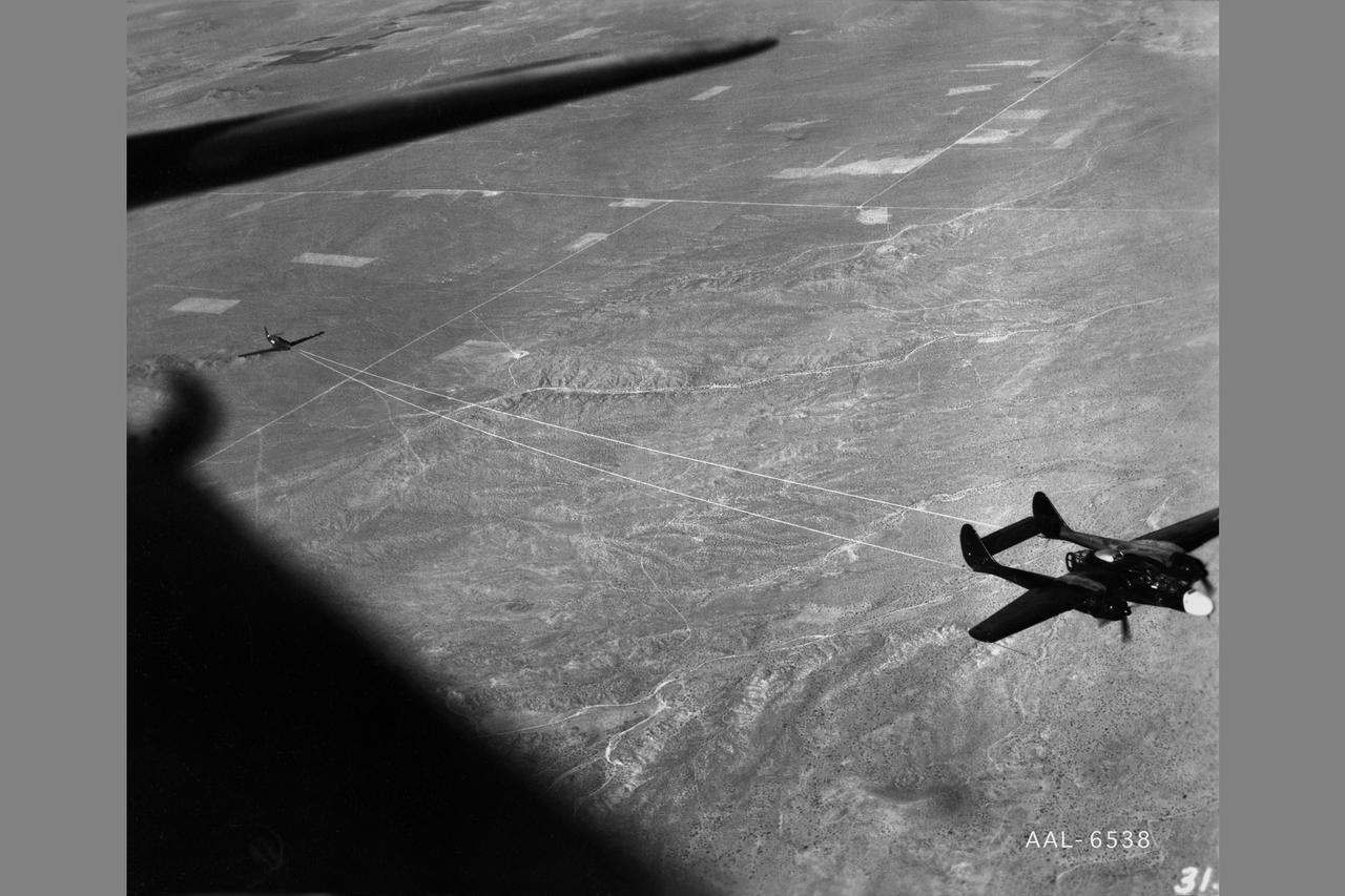
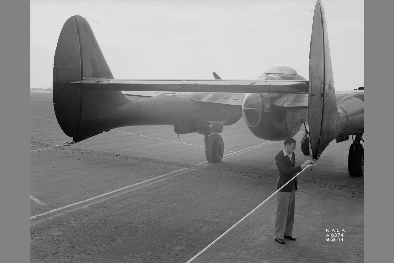
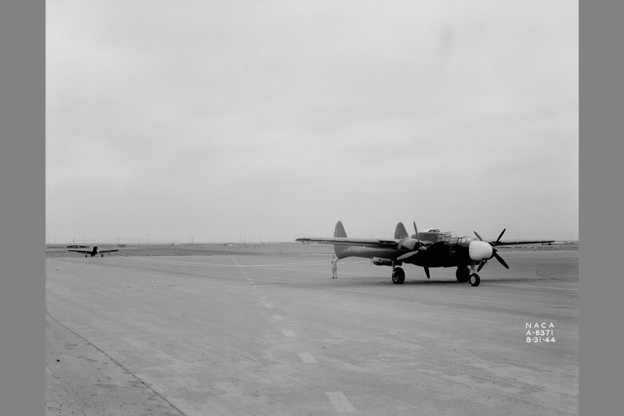
NACA photographer Northrop P-61A Black Widow towing P-51B to release altitude of 28,000 ft over Muroc Dry Lake, California for in flight validating of wind tunnel measurements of drag. After the pilot released the tow cable, drag measurementrs were obtained at various airspeeds in a 20-minute unpowered flight. Note: Used in publication in Flight Research at Ames; 57 Years of Development and Validation of Aeronautical Technology NASA SP-1998-3300 Fig. 17
B-32 Model Close Up. Test conducted in the NACA 19 foot pressure tunnel LMAL-38560 NACA document.
Towing installations on P-51 and P-61 airplanes for propeller off tests on the P-51 Front view of P-51 & P-61 in towing position preparing for take off at NACA Ames Research Center, Moffett Field, California
NAS Moffett Field Naval Air Station, Mt. View, Ca Altitude 1300ft E.S. East

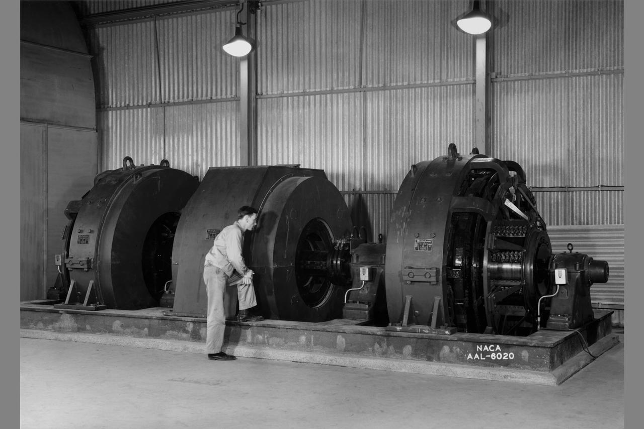
These compressors inside the Refrigeration Building at the National Advisory Committee for Aeronautics (NACA) Aircraft Engine Research Laboratory were used to generate cold temperatures in the Altitude Wind Tunnel (AWT) and Icing Research Tunnel. The AWT was a large facility that simulated actual flight conditions at high altitudes. The two primary aspects of altitude simulation are the reduction of the air pressure and the decrease of temperature. The Icing Research Tunnel was a smaller facility in which water droplets were added to the refrigerated air stream to simulate weather conditions that produced ice buildup on aircraft. The military pressured the NACA to complete the tunnels quickly so they could be of use during World War II. The NACA engineers struggled with the design of this refrigeration system, so Willis Carrier, whose Carrier Corporation had pioneered modern refrigeration, took on the project. The Carrier engineers devised the largest cooling system of its kind in the world. The system could lower the tunnels’ air temperature to –47⁰ F. The cooling system was powered by 14 Carrier and York compressors, seen in this photograph, which were housed in the Refrigeration Building between the two wind tunnels. The compressors converted the Freon 12 refrigerant into a liquid. The refrigerant was then pumped into zig-zag banks of cooling coils inside the tunnels’ return leg. The Freon absorbed heat from the airflow as it passed through the coils. The heat was transferred to the cooling water and sent to the cooling tower where it was dissipated into the atmosphere.
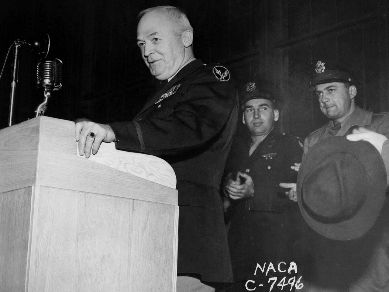
General Henry “Hap” Arnold, Commander of the US Army Air Forces during World War II, addresses the staff at the National Advisory Committee for Aeronautics (NACA) Aircraft Engine Research Laboratory on November 9, 1944. Arnold told the employees assembled in the hangar, “You’ve got a dual task. You’ve got a job ahead of you to keep the army and the navy air forces equipped with the finest equipment that you can for this war. You also have the job of looking forward into the future and starting now those developments, those experiments, that are going to keep us in our present situation—ahead of the world in the air. And that is quite a large order, and I leave it right in your laps.” Arnold served on the NACA’s Executive Committee in Washington from 1938 to 1944 and had been a strong advocate for the creation of the new engine research facility in Cleveland. Arnold believed in continual research and development. He pressed the nation’s aviation leaders to pursue the new jet engine technology, while simultaneously pushing to increase the performance of the nation’s largest piston engine for the B–29 Superfortress program. The general’s hectic wartime agenda limited his visit to the Cleveland laboratory to just a few hours, but he toured several of the NACA’s new test facilities including the Static Jet Propulsion Laboratory, the Icing Research Tunnel, and a B–24 Liberator in the hangar.
The resolution of the Boeing B-29 Superfortress’ engine cooling problems was one of the Aircraft Engine Research Laboratory’s (AERL) key contributions to the World War II effort. The B-29 leapfrogged previous bombers in size, speed, and altitude capabilities. The B–29 was intended to soar above anti-aircraft fire and make pinpoint bomb drops onto strategic targets. Four Wright Aeronautical R-3350 engines powered the massive aircraft. The engines, however, frequently strained and overheated due to payload overloading. This resulted in a growing number of engine fires that often resulted in crashes. The military asked the NACA to tackle the overheating issue. Full-scale engine tests on a R–3350 engine in the Prop House demonstrated that a NACA-designed impeller increased the fuel injection system’s flow rate. Single-cylinder studies resolved a valve failure problem by a slight extension of the cylinder head, and researchers in the Engine Research Building combated uneven heating with a new fuel injection system. Investigations during the summer of 1944 in the Altitude Wind Tunnel, which could simulate flight conditions at high altitudes, led to reduction of drag and improved air flow by reshaping the cowling inlet and outlet. The NACA modifications were then flight tested on a B-29 bomber that was brought to the AERL.

The Flight Operations crew stands before a Republic P-47G Thunderbolt at the National Advisory Committee for Aeronautics (NACA) Aircraft Engine Research Laboratory in Cleveland, Ohio. The laboratory’s Flight Research Section was responsible for conducting a variety of research flights. During World War II most of the test flights complemented the efforts in ground-based facilities to improve engine cooling systems or study advanced fuel mixtures. The Republic P–47G was loaned to the laboratory to test NACA modifications to the Wright R–2800 engine’s cooling system at higher altitudes. The laboratory has always maintained a fleet of aircraft so different research projects were often conducted concurrently. The flight research program requires an entire section of personnel to accomplish its work. This staff generally consists of a flight operations group, which includes the section chief, pilots and administrative staff; a flight maintenance group with technicians and mechanics responsible for inspecting aircraft, performing checkouts and installing and removing flight instruments; and a flight research group that integrates the researchers’ experiments into the aircraft. The staff at the time of this March 1944 photograph included 3 pilots, 16 planning and analysis engineers, 36 mechanics and technicians, 10 instrumentation specialists, 6 secretaries and 5 computers.
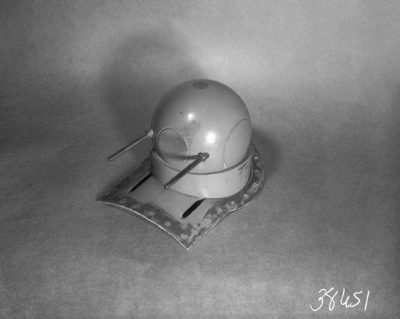
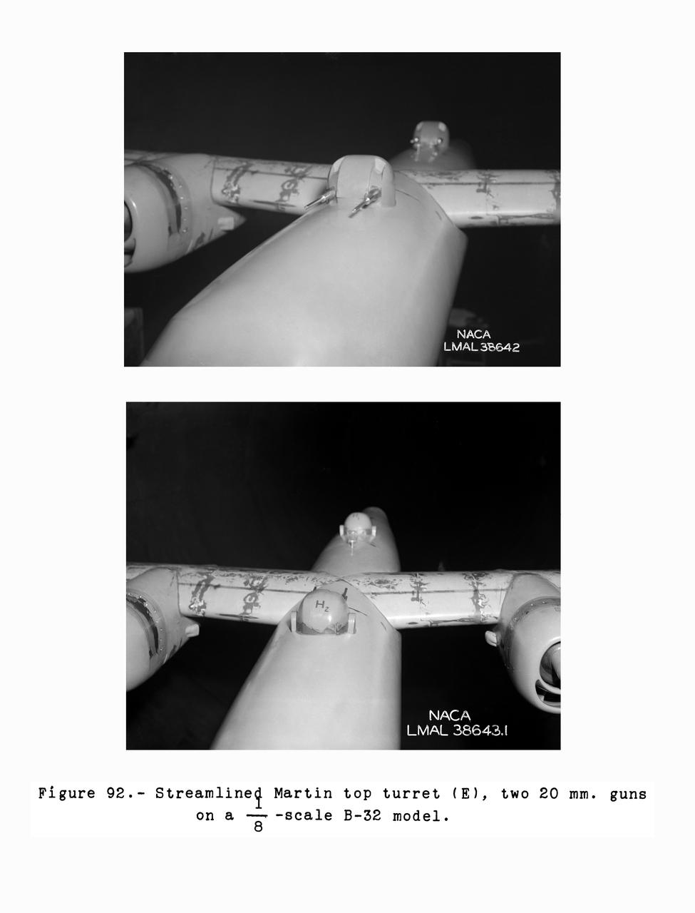
1/8 Scale B-32 Turrets. Test conducted in the NACA 19 foot pressure tunnel LMAL-38560 NACA document.
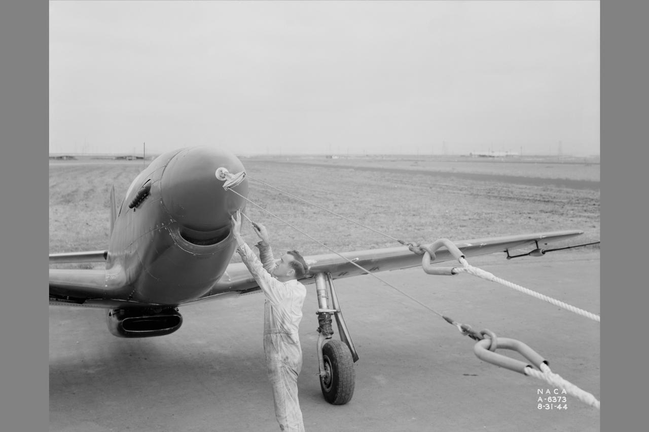
Towing installations on P-51 airplane for propeller off tests on the P-51 Front view of P-51 in towing position with P-61A preparing for take off at NACA Ames Research Center, Moffett Field, California
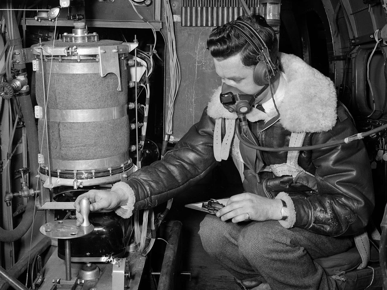
A flight engineer at the National Advisory Committee for Aeronautics (NACA) Aircraft Engine Research Laboratory monitors test equipment in the rear of the Lockheed RA–29 Hudson. Lockheed manufactured several variations of the light bomber in the late 1930s. The Hudson was one of the few military aircraft models available in large quantities during the early years of World War II, and both the US and British air forces utilized it as a patrol aircraft. The RA–29s were soon superseded by newer aircraft, but continued to serve as crew trainers, light cargo carriers and staff transports. The NACA flight engineers in the Planning and Analysis Section were responsible for working with researchers to install and monitor the experimental equipment on the NACA’s research aircraft. This process could require weeks or months. When larger aircraft, like the RA–29 Hudson, were utilized the flight engineers often participated in the flights. The NACA acquired their RA–29 in November 1943, and used the aircraft for fuel blend studies and instrumentation development. The Hudson also frequently served as a transportation vehicle for the staff and visitors. The RA–29 was transferred from the NACA in July 1945.
NASA Ames Research Center's 1x3 1/2ft wind tunnel (to illustrate 1946 budget)
A Bell P-39 Airacobra in the NACA Aircraft Engine Research Laboratory’s Icing Research Tunnel for a propeller deicing study. The tunnel, which began operation in June 1944, was built to study the formation of ice on aircraft surfaces and methods of preventing or eradicating that ice. Ice buildup adds extra weight to aircraft, effects aerodynamics, and sometimes blocks airflow through engines. NACA design engineers added the Icing Research Tunnel to the new AERL’s original layout to take advantage of the massive refrigeration system being constructed for the Altitude Wind Tunnel. The Icing Research Tunnel is a closed-loop atmospheric wind tunnel with a 6- by 9-foot test section. The tunnel can produce speeds up to 300 miles per hour and temperatures from about 30 to –45⁰ F. During World War II AERL researchers analyzed different ice protection systems for propeller, engine inlets, antennae, and wings in the icing tunnel. The P-39 was a vital low-altitude pursuit aircraft of the US during the war. NACA investigators investigated several methods of preventing ice buildup on the P-39’s propeller, including the use of internal and external electrical heaters, alcohol, and hot gases. They found that continual heating of the blades expended more energy than the aircraft could supply, so studies focused on intermittent heating. The results of the wind tunnel investigations were then compared to actual flight tests on aircraft.
Clark Y Airfoil. 3/4 front view of 8x48 foot Clark Y Airfoil mounted (inverted) in the 40x80 foot wind tunnel at NACA's Ames Research Center.
Towing installations on P-51 and P-61 airplanes for propeller off tests on the P-51. Rear view of P-61 in towing position preparing for take off at NACA Ames Research Center, Moffett Field, California
P-51 airplane model in the NACA Ames Research Center Transonic 16ft w.t.
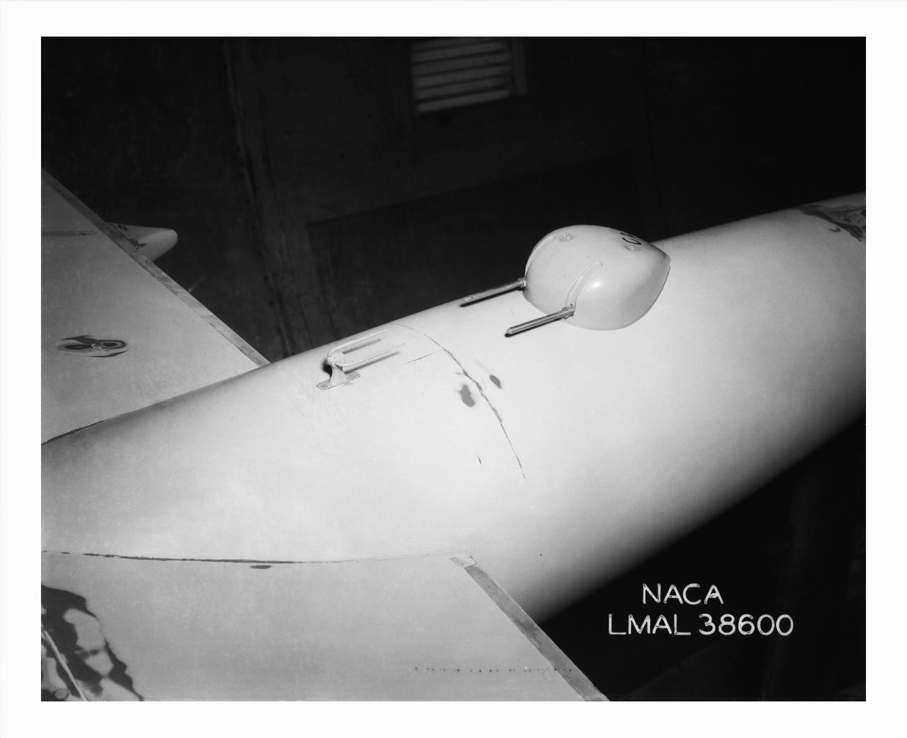
Detail Shots of B-32 Turret. Test conducted in the NACA 19 foot pressure tunnel LMAL-38560 NACA document.
PV-1 model; rear view with 2 1/2' x 2 1/2' trubulene net mount in the 7x10ft w.t. at Ames Research Center
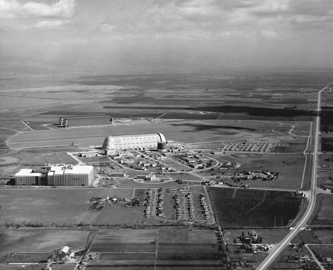
Looking beyond Hangar One toward Shenandoah Plaza (parade ground)
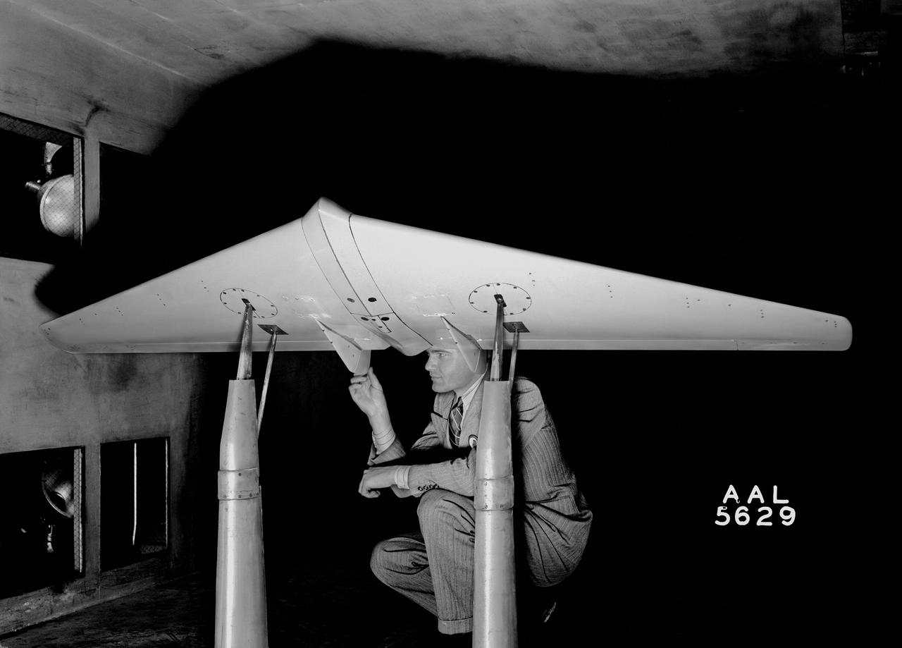
Avion MX-365 (XP-79) Wing 7x10ft w.t. @ Ames Research Center, Moffett Field, CA
N-221 Ames 40x80ft Subsonic wind tunnel construction; Constant speed - motor generator set.
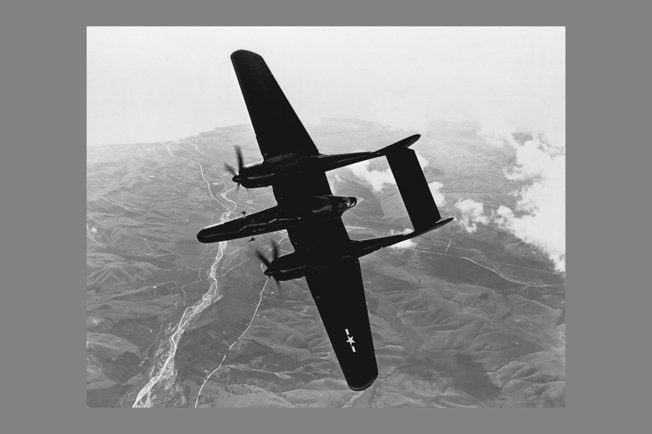
Northrop P-61C, Black Widow, Fighter, In-flight Photo
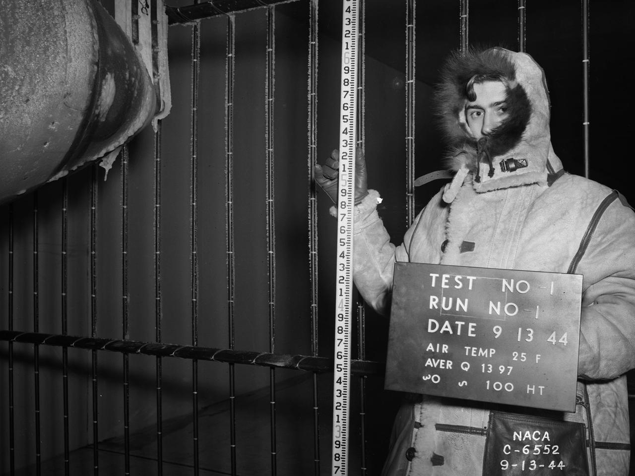
National Advisory Committee for Aeronautics (NACA) design engineers added the Icing Research Tunnel to the new Aircraft Engine Research Laboratory’s original layout to take advantage of the massive refrigeration system being constructed for the Altitude Wind Tunnel. The Icing Research Tunnel was built to study the formation of ice on aircraft surfaces and methods of preventing or eradicating that ice. Ice buildup adds extra weight, effects aerodynamics, and sometimes blocks airflow through engines. The Icing Research Tunnel is a closed-loop atmospheric wind tunnel with a 6- by 9-foot test section. The tunnel can produce speeds up to 300 miles per hour and temperatures from about 30 to –45⁰ F. Initially the tunnel used a spray bar system to introduce moisture into the airstream. NACA engineers struggled for nearly 10 years to perfect the spray system. The Icing Research Tunnel began testing in June of 1944. Initial testing, seen in this photograph, studied ice accumulation on propellers of a military aircraft. NACA reserach also produced a protected air scoop for the C–46 transport aircraft. A large number of C–46 aircraft were lost due to icing while flying supply runs over the Himalayas during World War II.
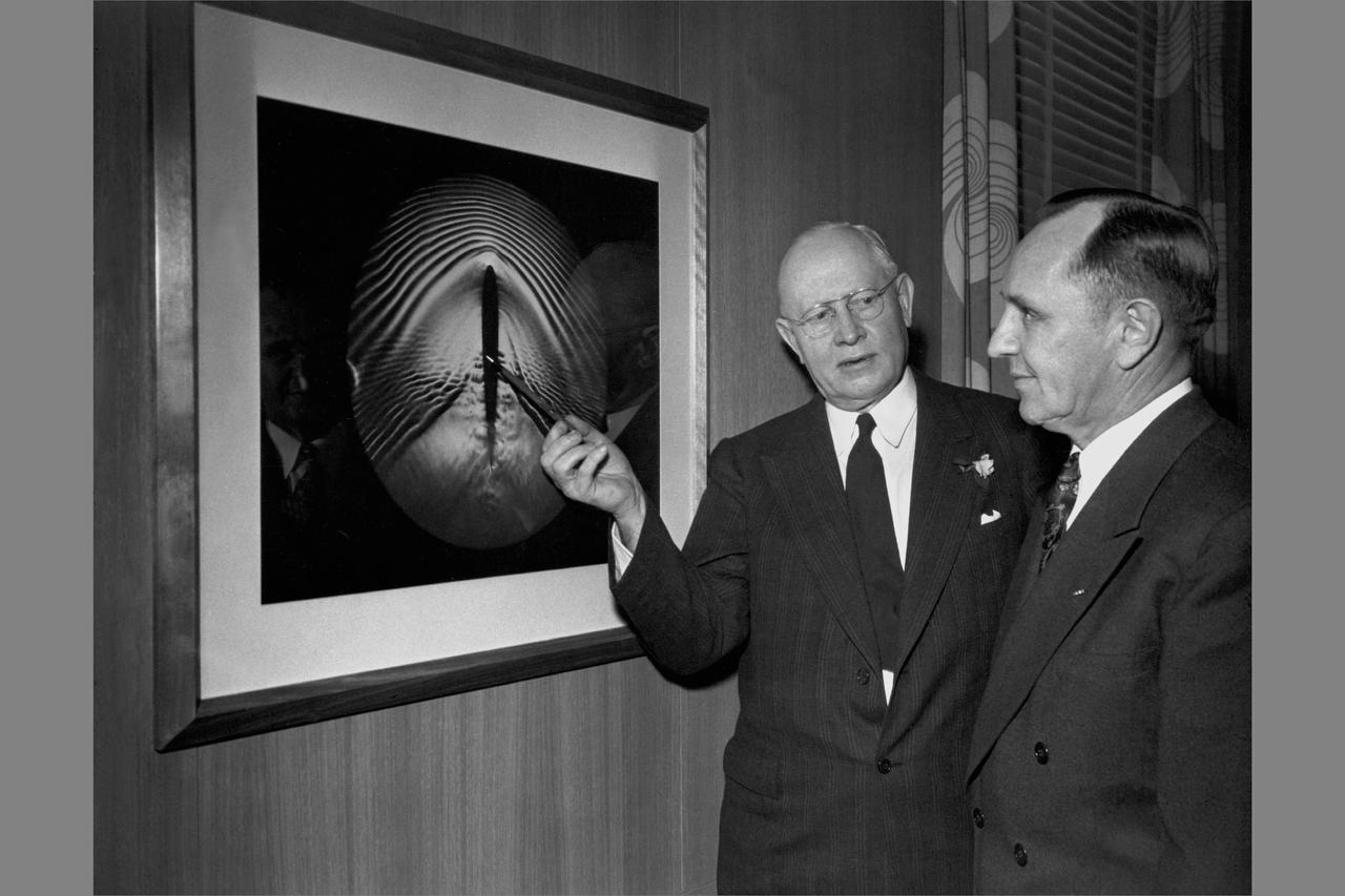
Ames Aeronautica Laboratory Dedication ceremonies; Dr. Lewis and Smity DeFrance, Director, Ames Research Center standing in front of shock-wave picture.
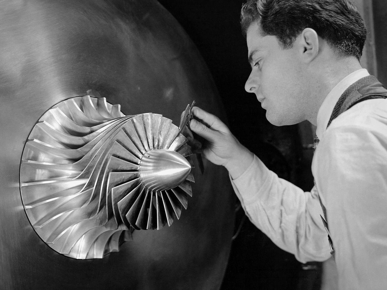
A researcher in the Supercharger Research Division at the National Advisory Committee for Aeronautics (NACA) Aircraft Engine Research Laboratory measures the blade thickness on a supercharger. Superchargers were developed at General Electric used to supply additional air to reciprocating engines. The extra air resulted in increased the engine’s performance, particularly at higher altitudes. The Aircraft Engine Research Laboratory had an entire division dedicated to superchargers during World War II. General Electric developed the supercharger in response to a 1917 request from the NACA to develop a device to enhance high-altitude flying. The supercharger pushed larger volumes of air into the engine manifold. The extra oxygen allowed the engine to operate at its optimal sea-level rating even when at high altitudes. Thus, the aircraft could maintain its climb rate, maneuverability and speed as it rose higher into the sky. NACA work on the supercharger ceased after World War II due to the arrival of the turbojet engine. The Supercharger Research Division was disbanded in October 1945 and reconstituted as the Compressor and Turbine Division.
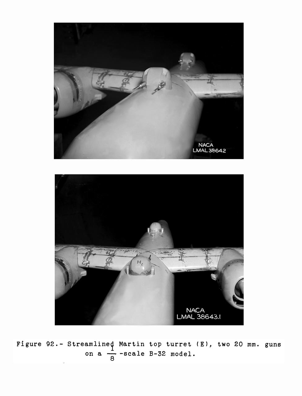
Gun Turrets of XP-35 Figure 92 Streamlined Martin Top Turret. B-33 Vega Turrets. Test conducted in the NACA 19 foot pressure tunnel LMAL-38560 NACA document.
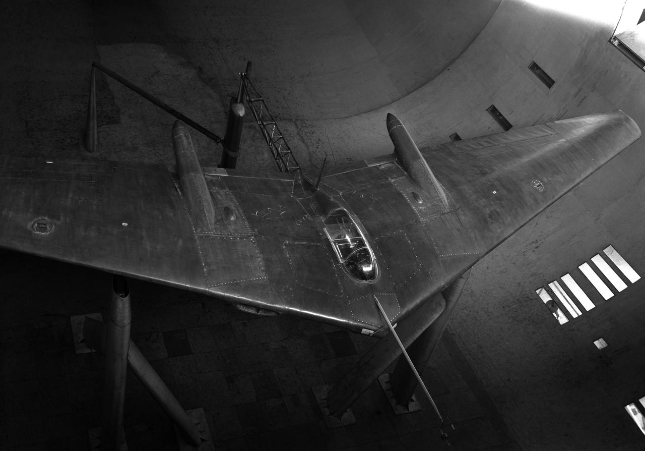
First airplane tested in the ames 40 x 80 foot wind tunnel. Douglas XSB2D-1 (Destroyer) hanging from overhead crane above the test section.
Northrop N9M-2 airplane; 3/4 front view from above.
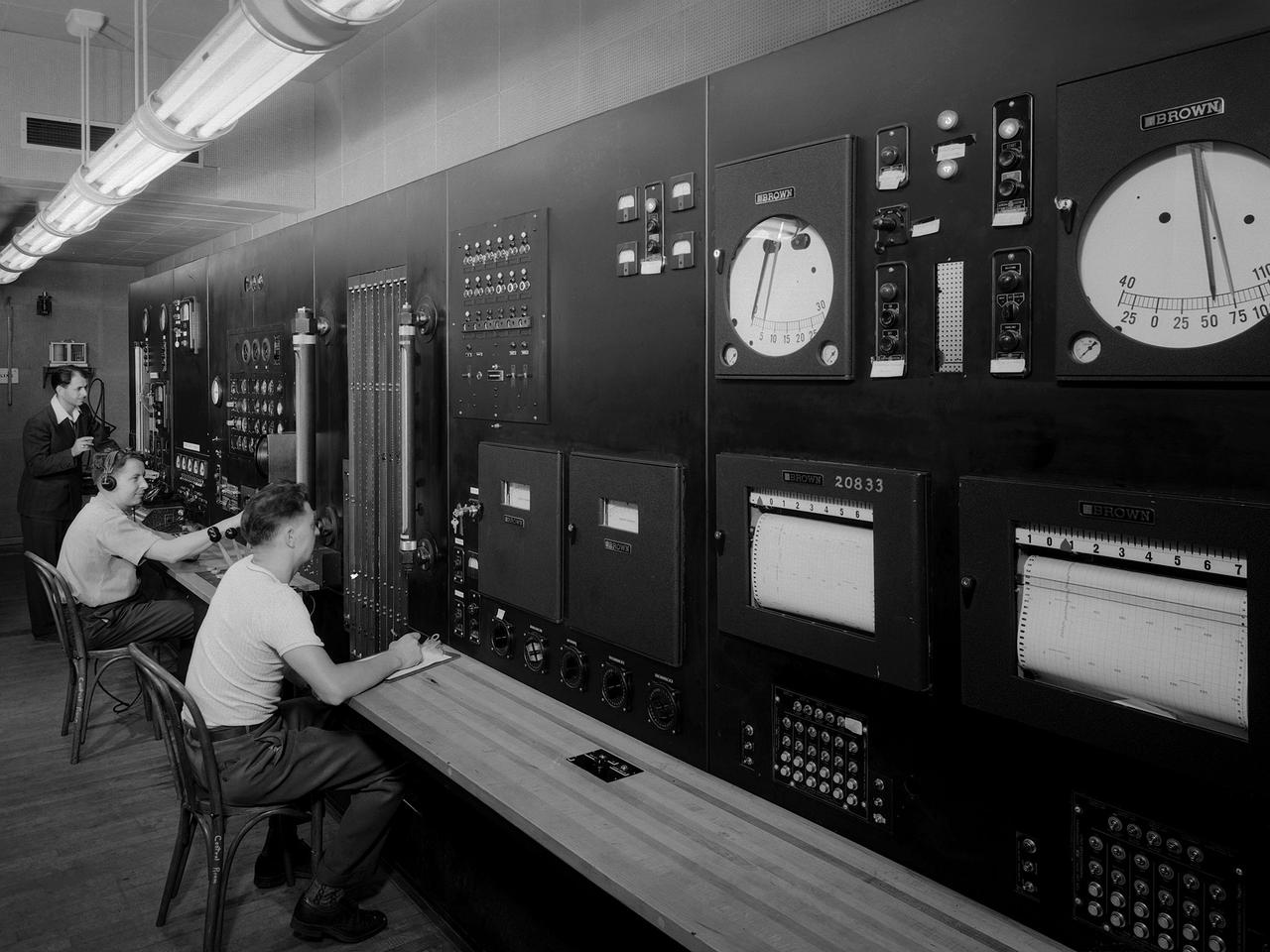
Operators in the control room for the Altitude Wind Tunnel at the National Advisory Committee for Aeronautics (NACA) Aircraft Engine Research Laboratory remotely operate a Wright R–3350 engine in the tunnel’s test section. Four of the engines were used to power the B–29 Superfortress, a critical weapon in the Pacific theater during World War II. The wind tunnel, which had been in operation for approximately six months, was the nation’s only wind tunnel capable of testing full-scale engines in simulated altitude conditions. The soundproof control room was used to operate the wind tunnel and control the engine being run in the test section. The operators worked with assistants in the adjacent Exhauster Building and Refrigeration Building to manage the large altitude simulation systems. The operator at the center console controlled the tunnel’s drive fan and operated the engine in the test section. Two sets of pneumatic levers near his right forearm controlled engine fuel flow, speed, and cooling. Panels on the opposite wall, out of view to the left, were used to manage the combustion air, refrigeration, and exhauster systems. The control panel also displayed the master air speed, altitude, and temperature gauges, as well as a plethora of pressure, temperature, and airflow readings from different locations on the engine. The operator to the right monitored the manometer tubes to determine the pressure levels. Despite just being a few feet away from the roaring engine, the control room remained quiet during the tests.
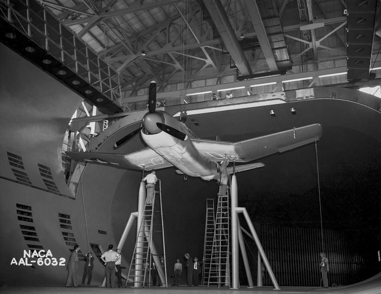
Test section of the Ames 40 x 80 foot wind tunnel with the overhead doors open. XSB2D-1 airplane being lowered onto the struts by the overhead crane. Mechanics and engineers on orchard ladders aligning the model with ball sockets on the struts. The Douglas BTD Destroyer was an American dive/ torpedo bomber developed for the United States Navy during World War II.
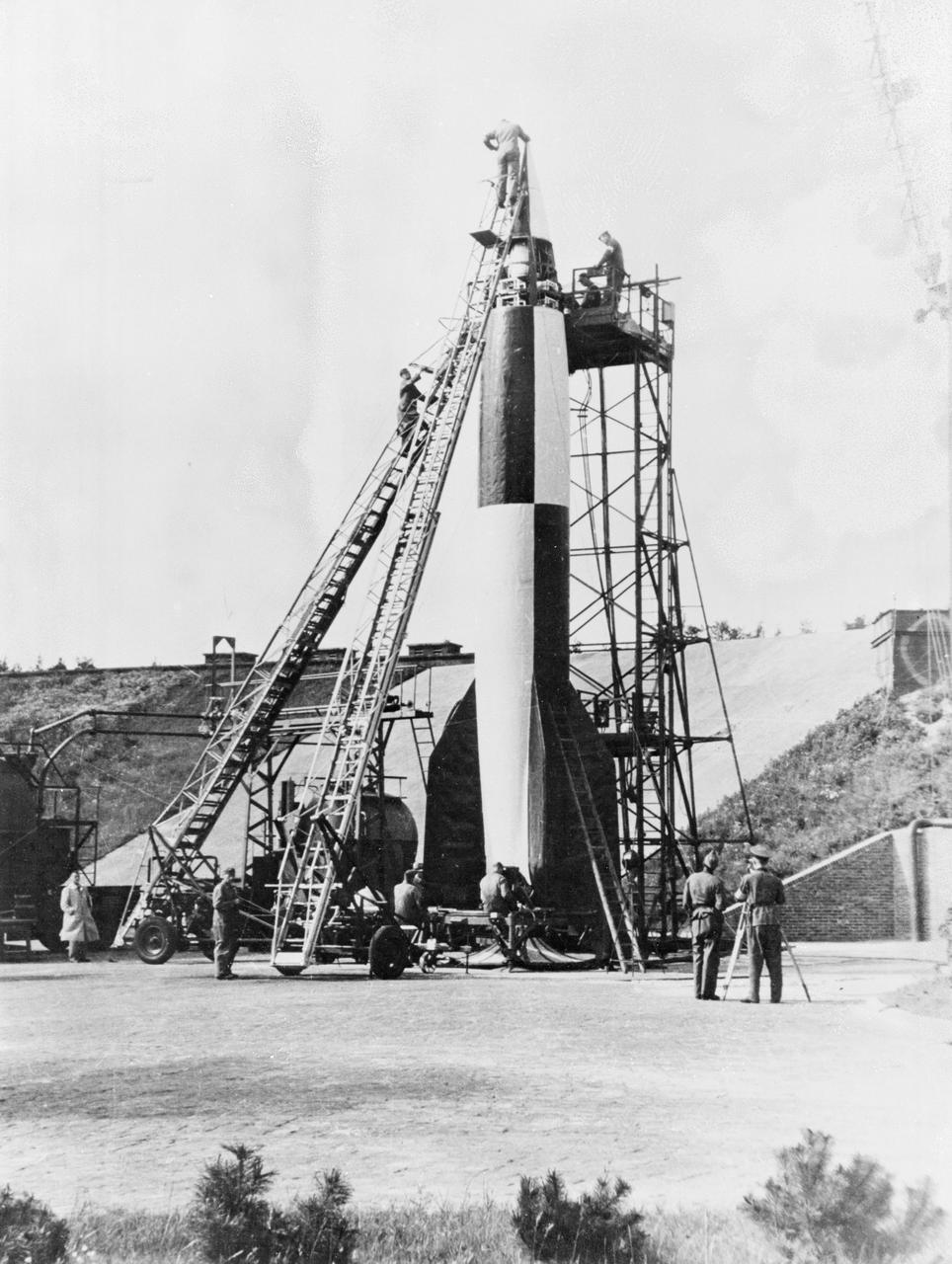
German technicians stack the various stages of the V-2 rocket in this undated photograph. The team of German engineers and scientists who developed the V-2 came to the United States at the end of World War II and worked for the U. S. Army at Fort Bliss, Texas, and Redstone Arsenal in Huntsville, Alabama.
P-61A Airplane at NACA Ames Research Center, Moffett Field, California
Detail Shots of B-32 Turret. Test conducted in the NACA 19 foot pressure tunnel LMAL-38560 NACA document.
3/4 rear view of the Ryan FR-1 airplane mounted in the NACA Ames 40x80 foot wind tunnel from below. Production configuration.
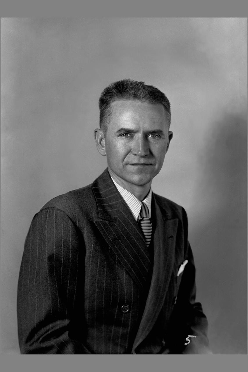
Portrait: Louis a. Rodert
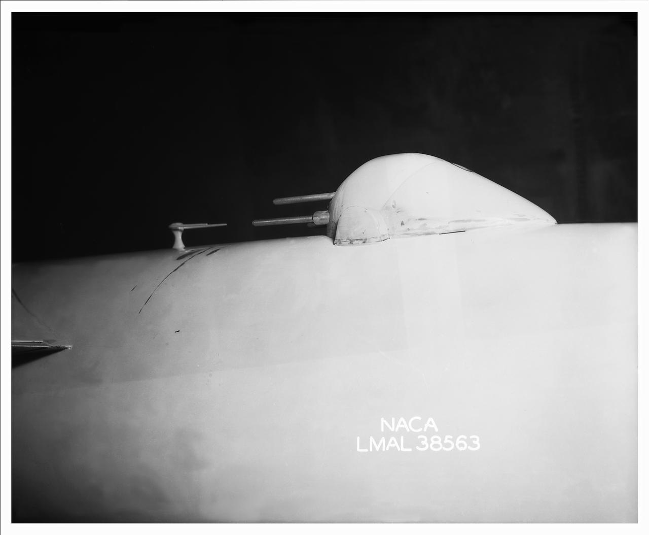
Detail Shots of B-32 Turret. Test conducted in the NACA 19 foot pressure tunnel LMAL-38560 NACA document.
B-32 Model Close Up. Test conducted in the NACA 19 foot pressure tunnel LMAL-38560 NACA document.
NASA Ames Research Center's 1x3 1/2 ft wind tunnel (to illustrate 1946 budget)
P-61A Airplane at NACA Ames Research Center, Moffett Field, California
3/4 rear view from below of Douglas BTD-1 airplane in Ames 40x80 foot Wind Tunnel, unseated, horizontal tail on.
View of the drive fan for the Icing Research Tunnel at the National Advisory Committee for Aeronautics (NACA) Aircraft Engine Research Laboratory in Cleveland, Ohio. The tunnel was built in the early 1940s to study the formation of ice on aircraft surfaces and methods of preventing or eradicating that ice. Ice buildup adds extra weight, effects aerodynamics, and sometimes blocks airflow through engines. The original 4100-horsepower induction motor was coupled directly to the 24-foot-diameter fan. The 12 wooden fan blades were protected on their leading edge by a neoprene boot. The system could create air speeds up to 300 miles per hour through the tunnel’s 6- by 9-foot test section. The large tail faring extending from the center of the fan is used to guide the airflow down the tunnel in a uniform way. A new 5000-horsepower motor was installed in 1987, and the original fan blades were replaced in 1993.
Gun Turrets of XP-35. Test conducted in the NACA 19 foot pressure tunnel LMAL-38560 NACA document.
Detail Shots of B-32 Turret. Test conducted in the NACA 19 foot pressure tunnel LMAL-38560 NACA document.
Gun Turrets of XP-35. Test conducted in the NACA 19 foot pressure tunnel LMAL-38560 NACA document.
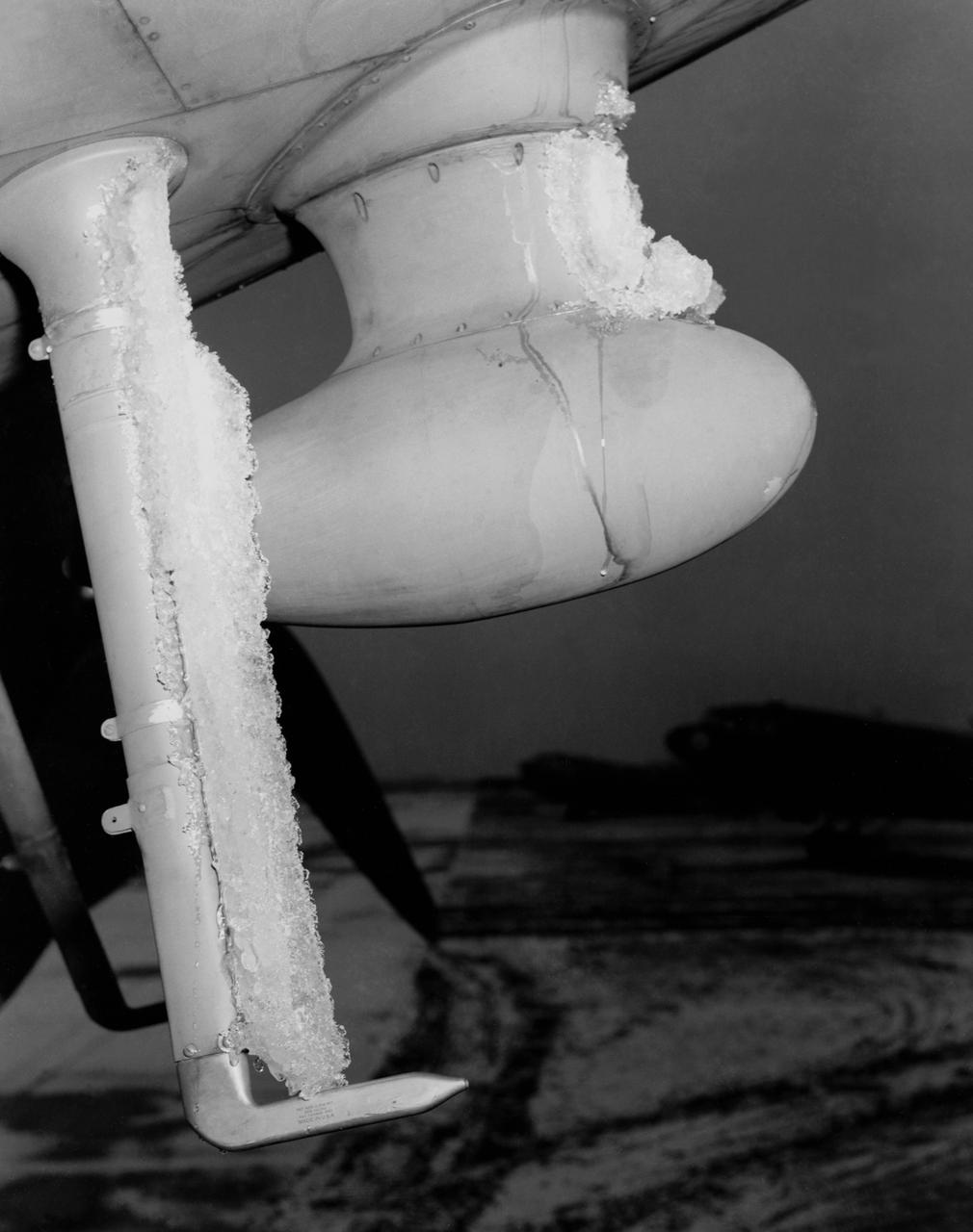
De-icing Research conducted at the NASA Ames Research Center. Icing flight test on C-46 airplane (flight 29 11:25am to 12:50 am) glaze ice on loop antenna co-pilots airspeed mast.
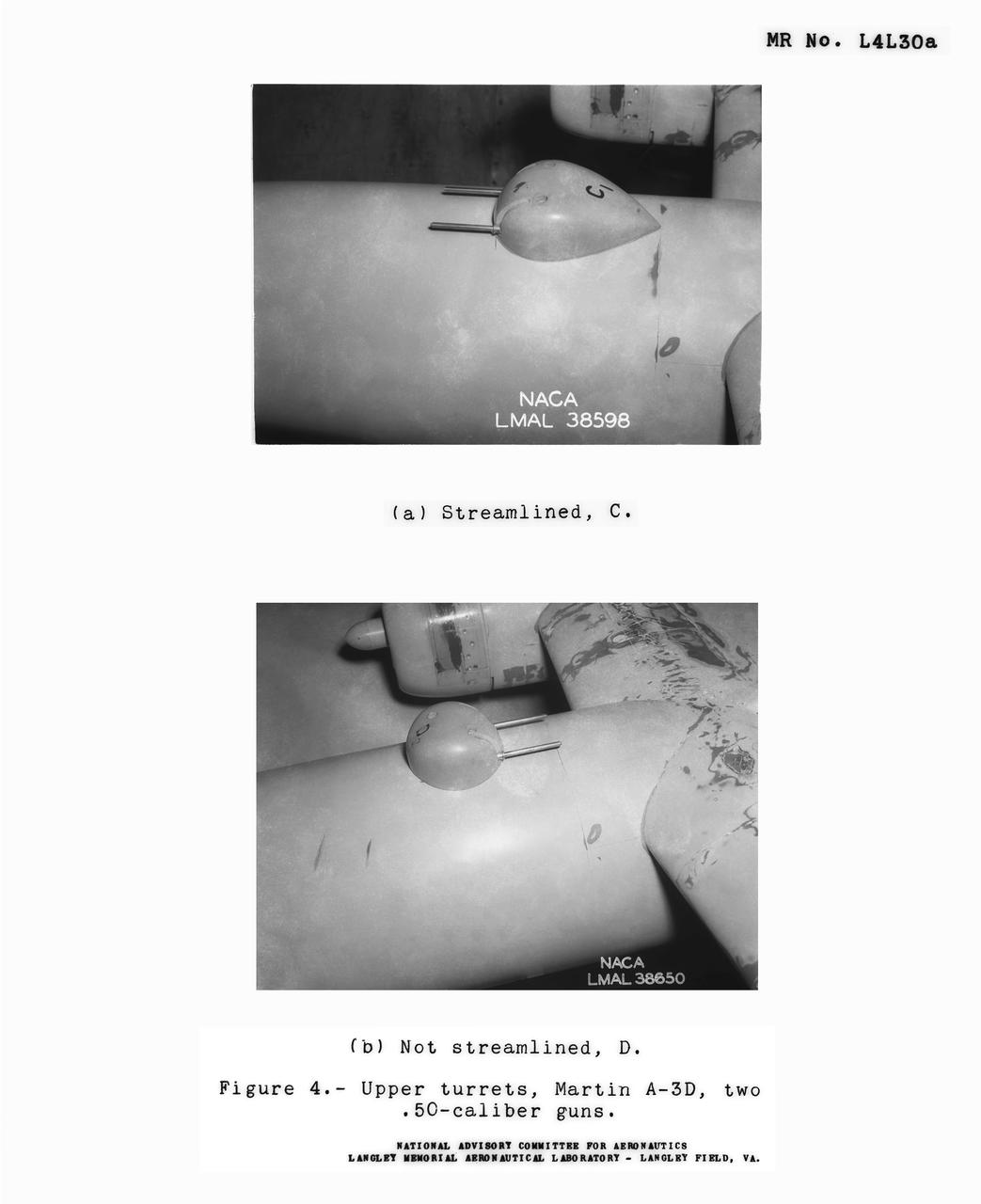
Detail Shots of B-32 Turret Figure 4. Upper turrets, Martin A-3D, Two .50 Caliber guns. Test conducted in the NACA 19 foot pressure tunnel LMAL-38560 NACA document.
Towing installations on P-51 and P-61 airplanes for propeller off tests on the P-51 Front view of P-51 & P-61 in towing position preparing for take off at NACA Ames Research Center, Moffett Field, California
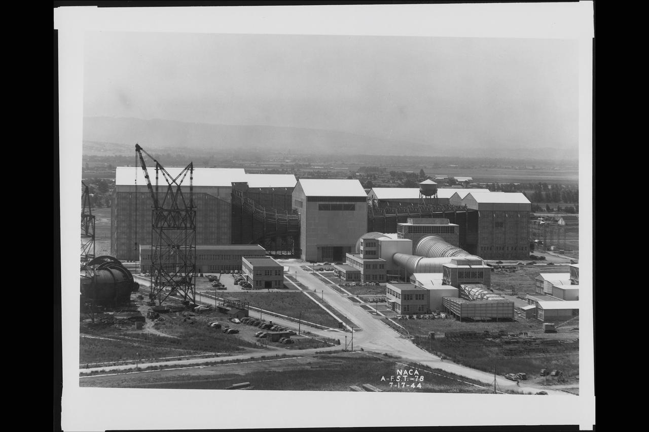
General view of Ames Subsonic 40x80ft wind tunnel from atop of the Moffett Naval Airship Hangar One (with construction of the Ames 12ft Pressure Wind Tunnel in forground) July 17, 1944
B-32 Model Close Up. Test conducted in the NACA 19 foot pressure tunnel LMAL-38560 NACA document.
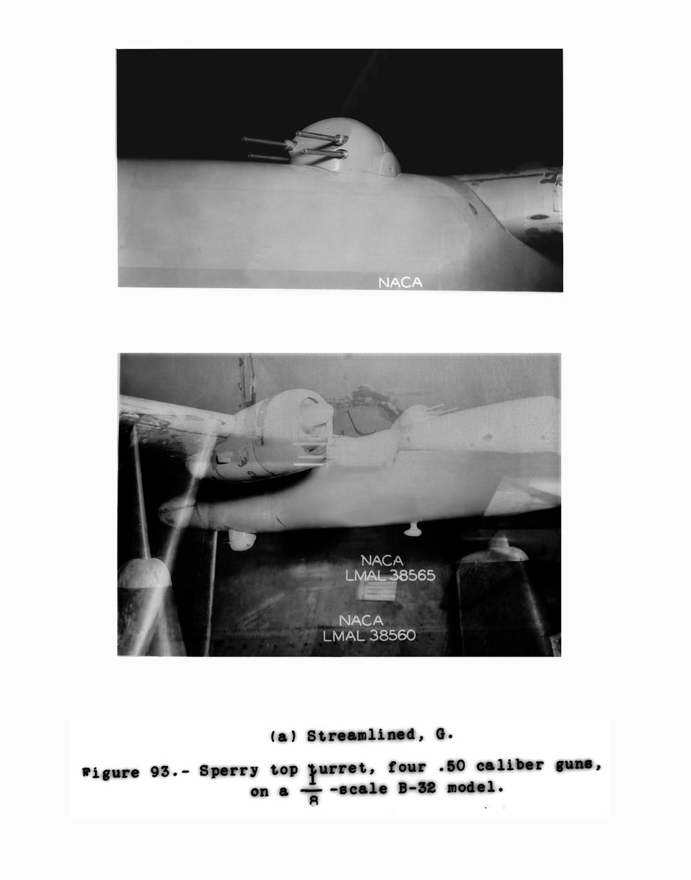
Detail Shots of B-32 Turret Figure 93. Test conducted in the NACA 19 foot pressure tunnel LMAL-38560 NACA document.
Detail Shots of B-32 Turret. Test conducted in the NACA 19 foot pressure tunnel LMAL-38560 NACA document.
Detail Shots of B-32 Turret. Test conducted in the NACA 19 foot pressure tunnel LMAL-38560 NACA document.
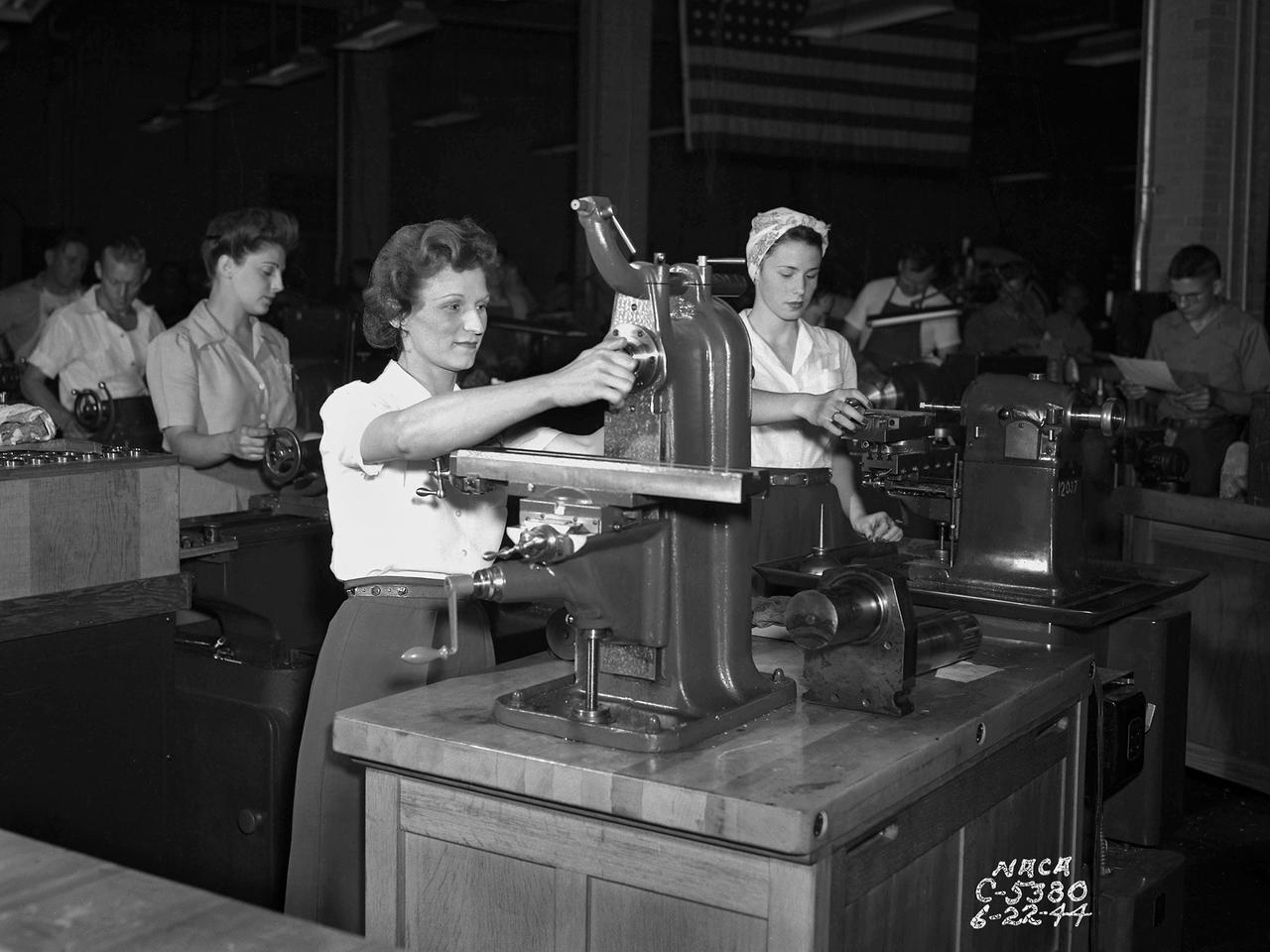
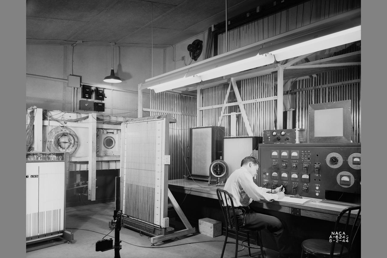
The loss of male NACA employees to the war effort and the military’s increased demand for expedited aeronautical research results resulted in a sharp demand for increased staffing in the early 1940s. The Aircraft Engine Research Laboratory (AERL) undertook an extensive recruiting effort to remedy the situation. Current employees were asked to bring in friends and family members, including women. The number of women employed at the AERL nearly doubled to 412 between 1943 and 1944. In May 1944 Director Raymond Sharp initiated a program to train women as machine operators, electricians, instrumentation engineers, and other technical positions. The move coincided with the lab’s implementation of a third shift to meet the military’s demands for improved aircraft performance. There was also a modest, but important, number of female engineers and chemists, as well as large group employed in more traditional positions such as data analysts, editors, and clerks. The integration of women in the research process was critical. Researchers developed a test and submitted plans to the Drafting Section to be converted into blueprints. In some instances the Instrumentation Shop was asked to create instruments for the test. During the test, computers gathered and analyzed the data. The researcher then wrote the report which was reviewed by the Editorial Department and printed in the Duplication Unit. All of these tasks were generally performed by female employees.
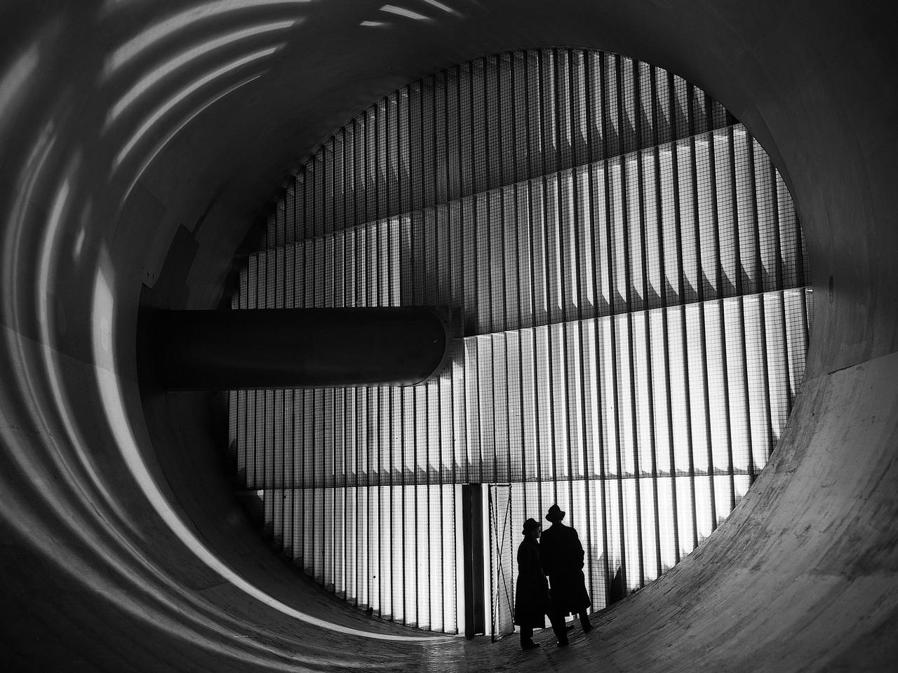
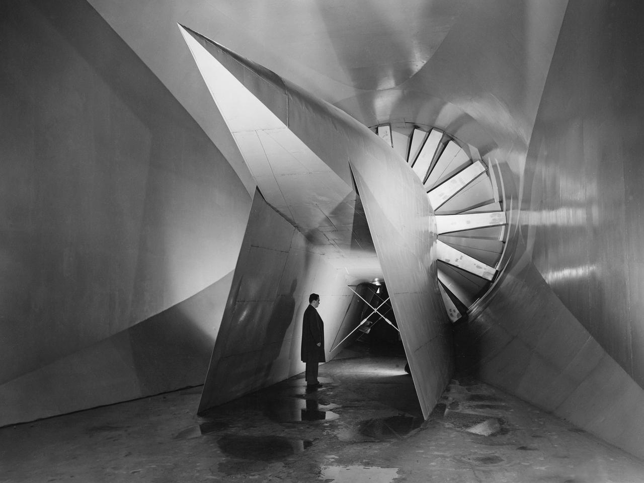
Men stand in front of turning vanes inside the Altitude Wind Tunnel (AWT) at the National Advisory Committee for Aeronautics (NACA) Aircraft Engine Research Laboratory. The AWT was the only wind tunnel capable of testing full-size aircraft engines in simulated altitude conditions. A large wooden drive fan, located on the other side of these vanes, created wind speeds up to 500 miles per hour. The drive shaft connected the fan to the induction motor located in an adjacent building. Turning vanes were located in each corner of the rectangular tunnel to straighten the airflow and direct it around the corners. This set of vanes was located in the 31-foot-diameter southeast corner of the tunnel. These elliptical panels consisted of 36 to 42 vertical vanes that were supported by three horizontal supports. The individual vanes were 2.5 feet long and half-moon shaped. The panel of vanes was affixed to the curved corner rings of the tunnel. Each set of turning vanes had a moveable vane in the middle of the lower level for personnel access. Each set of vanes took weeks to assemble before they were installed during the summer of 1943. This publicity photograph was taken just weeks after the tunnel became operational in February 1944.
P-51 airplane model in the NACA Ames Research Center Transonic 16ft wind tunnel
XSB2D-1 First test (no number) Aerodynamic test to forecast the take off distance. George Cooper was the A1:H73 pilot. Orchard ladders were used to access the ball socket attachments on the struts.