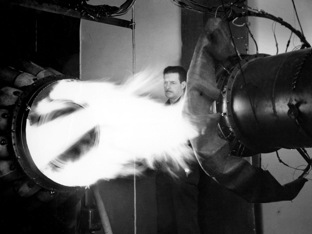
A mechanic watches the firing of a General Electric I-40 turbojet at the National Advisory Committee for Aeronautics (NACA) Lewis Flight Propulsion Laboratory. The military selected General Electric’s West Lynn facility in 1941 to secretly replicate the centrifugal turbojet engine designed by British engineer Frank Whittle. General Electric’s first attempt, the I-A, was fraught with problems. The design was improved somewhat with the subsequent I-16 engine. It was not until the engine's next reincarnation as the I-40 in 1943 that General Electric’s efforts paid off. The 4000-pound thrust I-40 was incorporated into the Lockheed Shooting Star airframe and successfully flown in June 1944. The Shooting Star became the US’s first successful jet aircraft and the first US aircraft to reach 500 miles per hour. NACA Lewis studied all of General Electric’s centrifugal turbojet models during the 1940s. In 1945 the entire Shooting Star aircraft was investigated in the Altitude Wind Tunnel. Engine compressor performance and augmentation by water injection; comparison of different fuel blends in a single combustor; and air-cooled rotors were studied. The mechanic in this photograph watches the firing of a full-scale I-40 in the Jet Propulsion Static Laboratory. The facility was quickly built in 1943 specifically in order to test the early General Electric turbojets. The I-A was secretly analyzed in the facility during the fall of 1943.
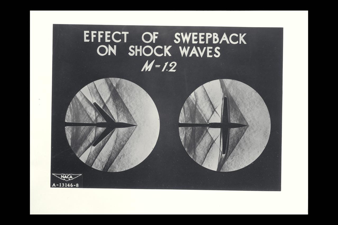
NACA Photographer/Graphic Supersonic Research: Schlieren photograph of the flow around airplane models showing effect of Sweptback on Shock Waves - M =1.2 (composite of shadowgraph samples on sweptback and straight wings
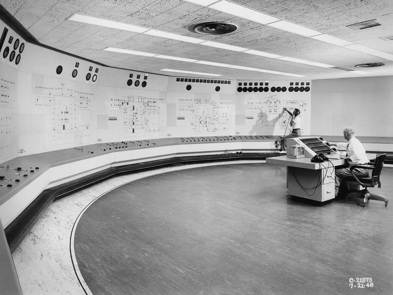
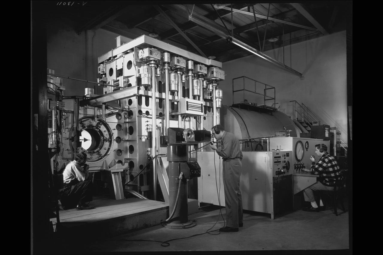
Operators in the Engine Research Building’s Central Control Room at the National Advisory Committee for Aeronautics (NACA) Lewis Flight Propulsion Laboratory. The massive 4.25-acre Engine Research Building contains dozens of test cells, test stands, and altitude chambers. A powerful collection of compressors and exhausters located in the central portion of the basement provided process air and exhaust for these test areas. This system is connected to similar process air systems in the laboratory’s other large test facilities. The Central Control Room coordinates this activity and communicates with the local utilities. This photograph was taken just after a major upgrade to the control room in 1948. The panels on the wall contain rudimentary floor plans of the different Engine Research Building sections with indicator lights and instrumentation for each test cell. The process air equipment included 12 exhausters, four compressors, a refrigeration system, cooling water, and an exhaust system. The operators in the control room kept in contact with engineers running the process air system and those conducting the tests in the test cells. The operators also coordinated with the local power companies to make sure enough electricity was available to operate the powerful compressors and exhausters.
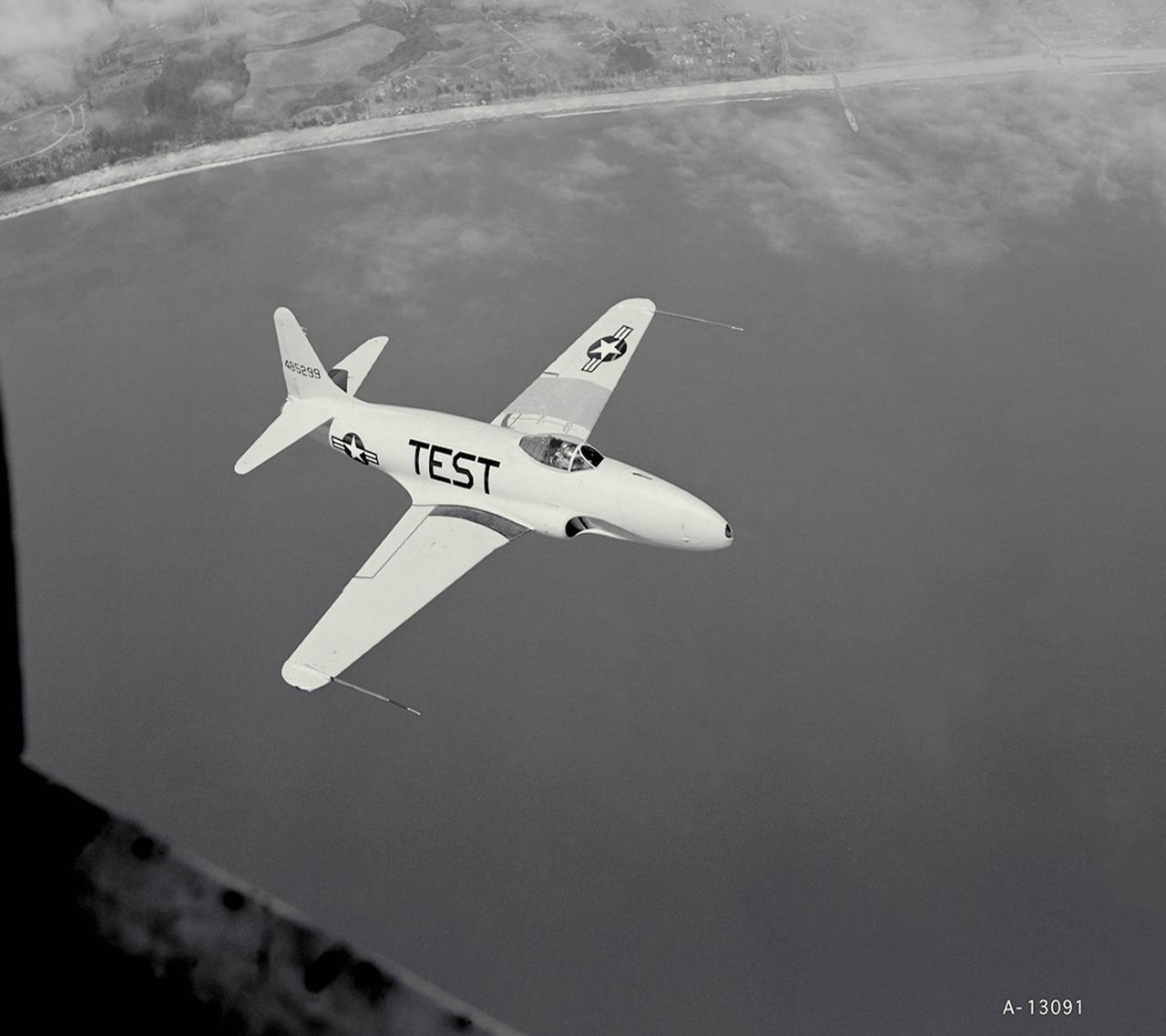
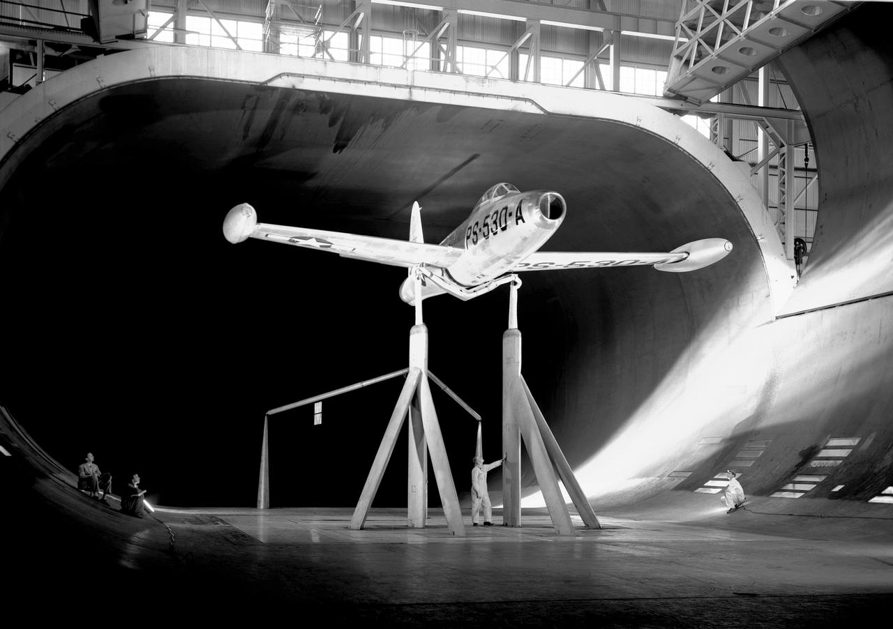
Investigation of Flying Qualities on the Lockheed P-80A airplane plan view Note: Used in publication in Flight Research at Ames; 57 Years of Development and Validation of Aeronautical Technology
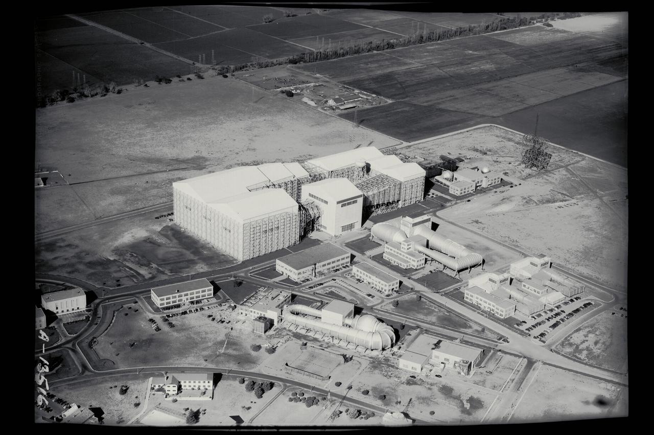
Ames Aerial - 40x80ft wind tunnel
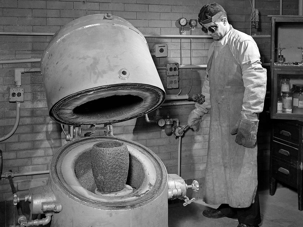
A technician prepares a metal component for a high-temperature bake in the Heat Treatment Shop at the National Advisory Committee for Aeronautics (NACA) Lewis Flight Propulsion Laboratory. Fabrication Division under Dan White and John Dalgleish created almost all of the equipment and models used at the laboratory. The Technical Services Building, referred to as the Fab Shop, contained a number of specialized shops in the 1940s and 1950s. These included a Machine Shop, Sheet Metal Shop, Wood and Pattern Shop, Instrument Shop, Thermocouple Shop, Heat Treating Shop, Metallurgical Laboratory, and Fabrication Office. The Metallurgical Laboratory contained a control lab for the Heat Treating Shop and a service lab for the NACA Lewis research divisions. This metallurgical group performed tensile and impact tests on metals to determine their suitability for specific research or equipment. The Heat Treating Shop heated metal parts to optimize their physical properties and contained a Precision Castings Foundry to manufacture equipment made of heat resisting alloys.
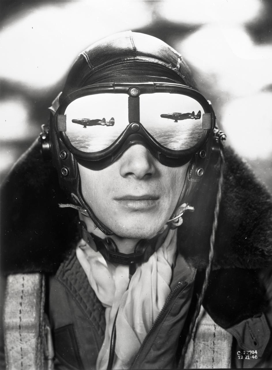
Flight engineer and photographer William Wynne (pictured) worked with photographer Arthur Laufman to execute a photo concept devised by Laufman. Wynne printed two copies of the F-61 aircraft in flight. The prints were made to the correct size that allowed them to be cut out and taped to the lenses of his goggles to simulate a reflection. The photo of Wynne was then taken with an out of focus background to simulate clouds.

The sign near the entrance of the National Advisory Committee for Aeronautics (NACA) Flight Propulsion Research Laboratory. The name was changed several weeks later to the Lewis Flight Propulsion Laboratory in honor of the NACA’s former Director of Aeronautical Research, George W. Lewis. The research laboratory has had five different names since its inception in 1941. The Cleveland laboratory was originally known as the NACA Aircraft Engine Research Laboratory. In 1947 it was renamed the NACA Flight Propulsion Research Laboratory to reflect the expansion of the research activities beyond just engines. Following the death of George Lewis, the name was changed to the NACA Lewis Flight Propulsion Laboratory in September 1948. On October 1, 1958, the lab was incorporated into the new NASA space agency, and it was renamed the NASA Lewis Research Center. Following John Glenn’s flight on the space shuttle, the name was changed again to the NASA Glenn Research Center on March 1, 1999. From his office in Washington DC, George Lewis managed the aeronautical research conducted at the NACA for over 20 years. His most important accomplishment, however, may have been an investigative tour of German research facilities in the fall of 1936. The visit resulted in the broadening of the scope of the NACA’s research and the physical expansion that included the new engine laboratory in Cleveland.
McDonald XP-85
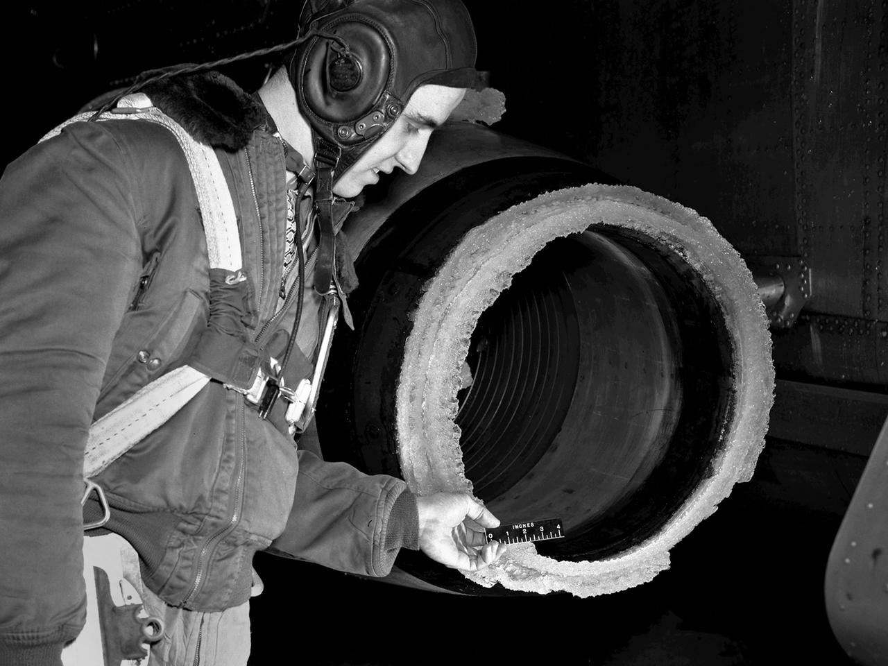
The National Advisory Committee for Aeronautics (NACA) Lewis Flight Propulsion Laboratory conducted an extensive icing research program in the late 1940s that included studies in the Icing Research Tunnel and using specially modified aircraft. One facet of this program was the investigation of the effects of icing on turbojets. Although jet engines allowed aircraft to pass through inclement weather at high rates of speed, ice accumulation was still a concern. The NACA’s B-24M Liberator was initially reconfigured with a General Electric I-16 engine installed in the aircraft’s waist compartment with an air scoop and spray nozzles to produce the artificial icing conditions. The centrifugal engine appeared nearly impervious to the effects of icing. Axial-flow jet engines, however, were much more susceptible to icing damage. The inlet guide vanes were particularly vulnerable, but the cowling’s leading edge, the main bearing supports, and accessory housing could also ice up. If pieces of ice reached the engine’s internal components, the compressor blades could be damaged. To study this phenomenon, a Westinghouse 24C turbojet, seen in this photograph, was installed under the B-24M’s right wing. In January 1948 flight tests of the 24C in icing conditions began. Despite ice buildup into the second stage of the compressor, the engine was able to operate at takeoff speeds. Researchers found the ice on the inlet vanes resulted in half of the engine’s decreased performance.
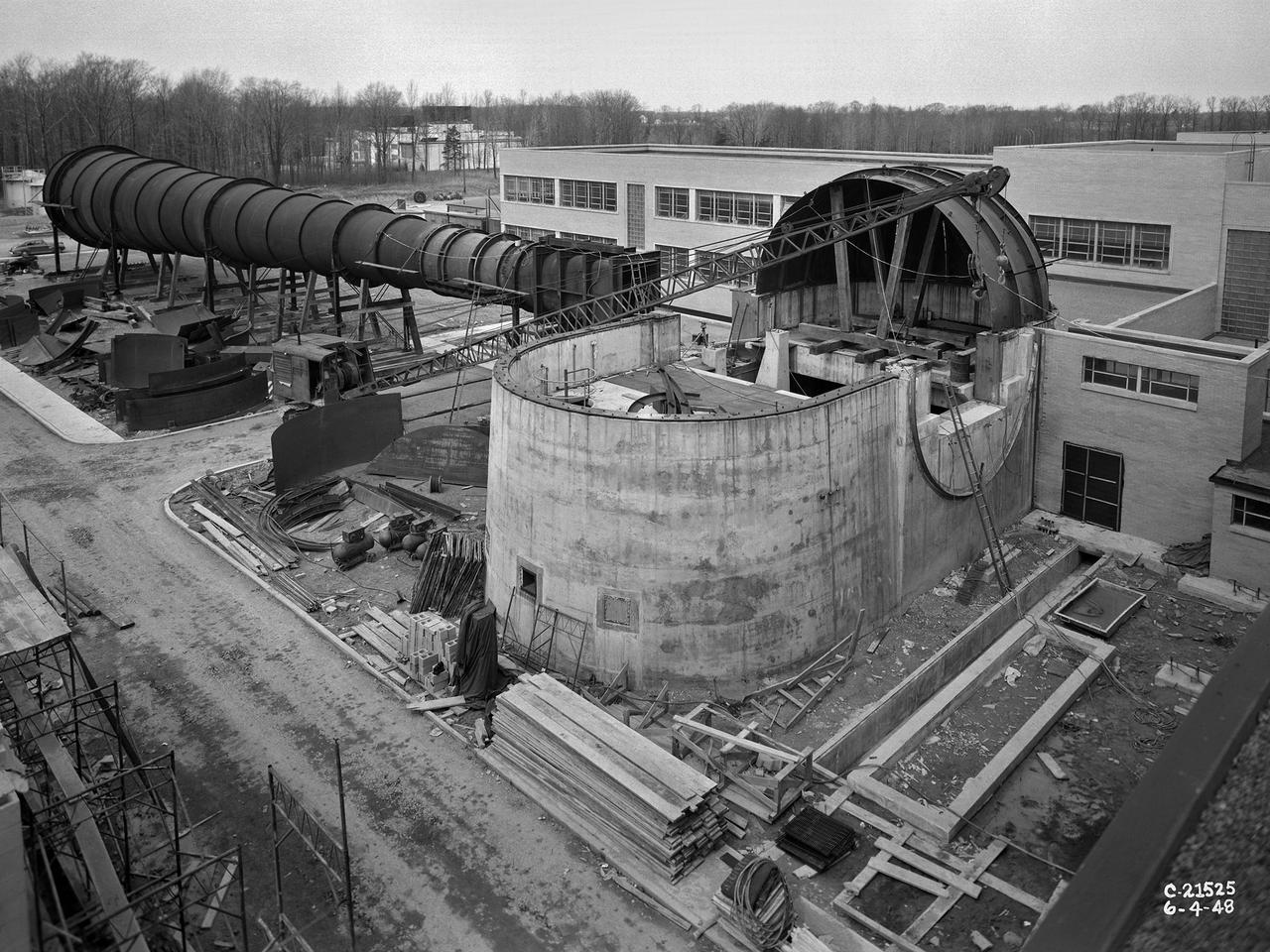
The 8- by 6-Foot Supersonic Wind Tunnel at the National Advisory Committee for Aeronautics (NACA) Lewis Flight Propulsion Laboratory was the nation’s largest supersonic facility when it began operation in April 1949. The emergence of new propulsion technologies such as turbojets, ramjets, and rockets during World War II forced the NACA and the aircraft industry to develop new research tools. In late 1945 the NACA began design work for new large supersonic wind tunnels at its three laboratories. The result was the 4- by 4-Foot Supersonic Wind Tunnel at Langley Memorial Aeronautical Laboratory, 6- by 6-foot supersonic wind tunnel at Ames Aeronautical Laboratory, and the largest facility, the 8- by 6-Foot Supersonic Wind Tunnel in Cleveland. The two former tunnels were to study aerodynamics, while the 8- by 6 facility was designed for supersonic propulsion. The 8- by 6-Foot Supersonic Wind Tunnel was used to study propulsion systems, including inlets and exit nozzles, combustion fuel injectors, flame holders, exit nozzles, and controls on ramjet and turbojet engines. Flexible sidewalls alter the tunnel’s nozzle shape to vary the Mach number during operation. A seven-stage axial compressor, driven by three electric motors that yield a total of 87,000 horsepower, generates air speeds from Mach 0.36 to 2.0. A section of the tunnel is seen being erected in this photograph.
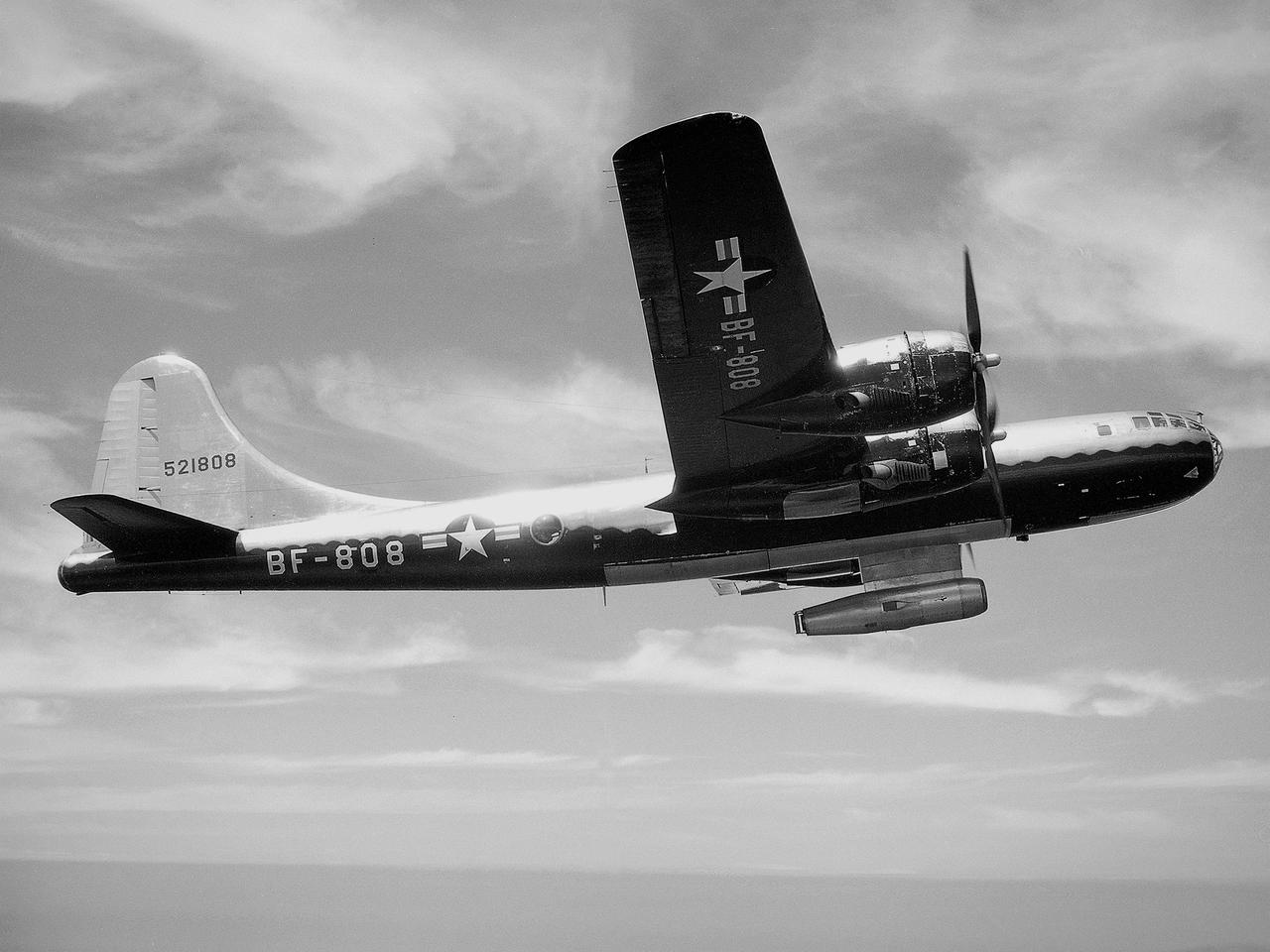
The NACA’s Lewis Flight Propulsion Laboratory used a Boeing B‒29 Superfortress as a testbed for ramjet investigations in the late 1940s. Lewis researchers conducted a wide variety of studies on ramjets to determine basic the operational data necessary to design missiles. Extensive wind tunnel and test stand studies were augmented by actual flight tests. Lewis engineers modified this B‒29 so that the ramjet could be stored in the bomb bay. Once the aircraft reached the desired altitude and speed, a mechanical arm suspended the ramjet 52 inches below the bomb bay. The ramjet’s angle-of-attack could be independently adjusted, and a periscope permitted a view of the test article from inside the aircraft. Researchers took measurements in free-stream conditions at speeds up to Mach 0.51 and at altitudes ranging from 5,000 to 30,000 feet. They then shut the ramjet down and retracted it into the aircraft. The researchers first determined that 14,000 feet was the maximum altitude at which the engine could be ignited by spark. They used flares to start the engine at altitudes up to 30,000 feet. They were able to determine maximum combustion efficiencies, response time to changes in fuel flow, and minimum fuel-air ratios. Overall the ramjet operated well at all speeds and altitudes.
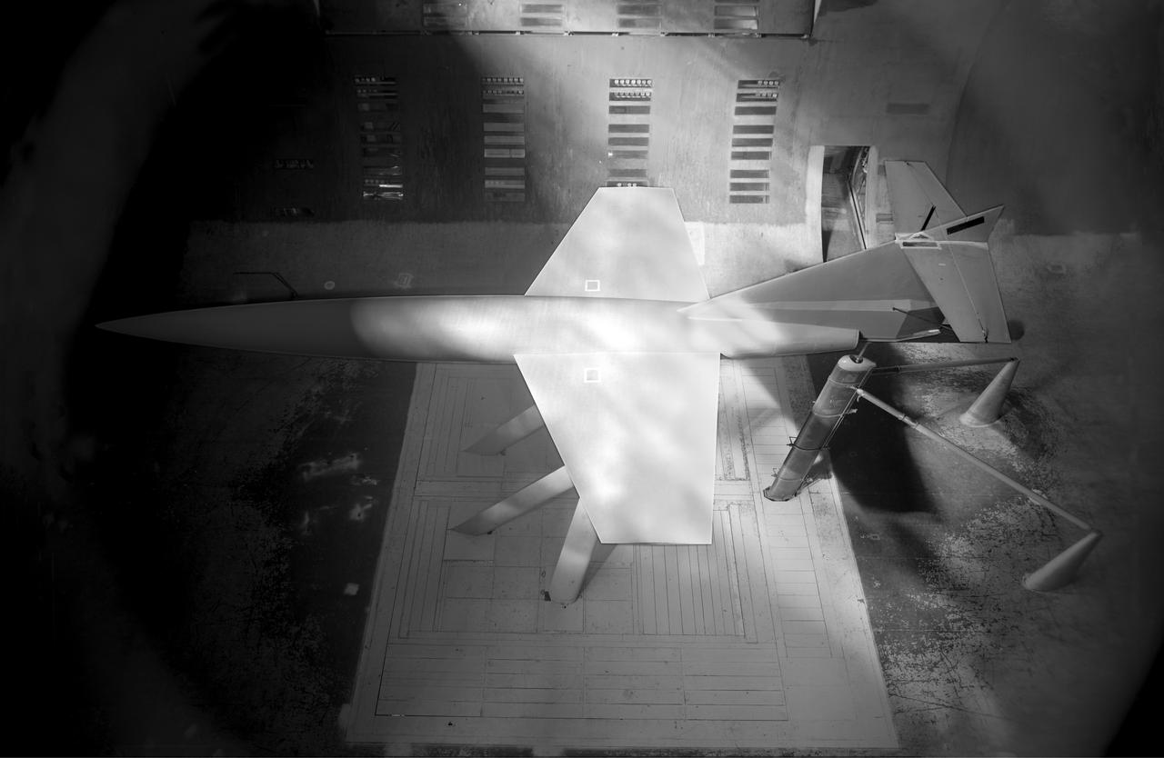
Front View of McDonald XP-85 Plan Model. Parasite Airplane designed to be carried in the B-36 bombay (never built) At the time it was the smallest Jet powered airplane. The McDonnell XF-85 Goblin was an American prototype fighter aircraft conceived during World War II by McDonnell Aircraft. It was intended to be deployed from the bomb bay of the giant Convair B-36 bomber as a parasite fighter. The XF-85's intended role was to defend bombers from hostile interceptor aircraft, a need demonstrated during World War II
NACA Photographer NASA Ames 1X3Ft W.T Blowdown, flexible throat: A swept wing model readied for a test in June 1948, in the 1 by 3 foot blowdown tunnel with a variable geometry throat mechanism
3/4 front view from below.
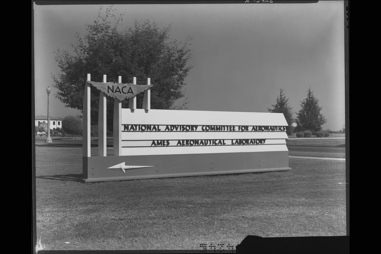
NACA (National Advisory Committee for Aeronautics) sign at entrance to Ames Laboratory
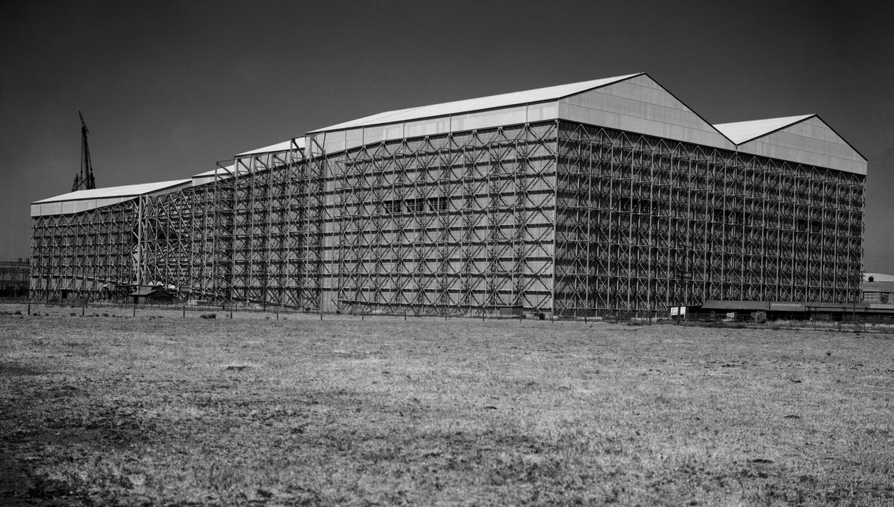
NACA Ames 40x80 foot wind tunnel (South West).