NACA PHOTOGRAPHER George Cooper, Ames Test Pilot
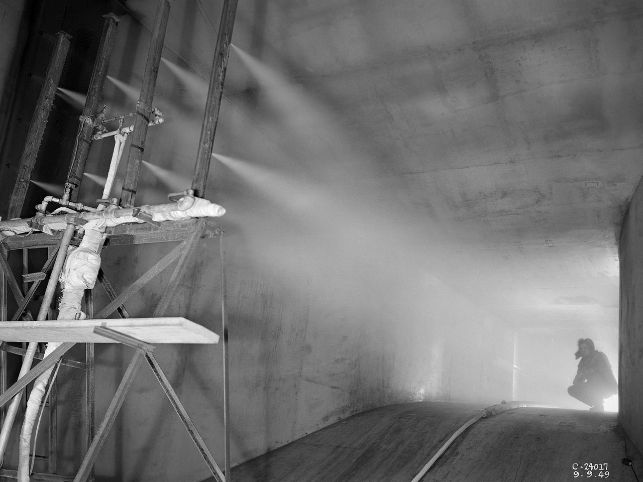
The spray bar system introduces water droplets into the Icing Research Tunnel’s air stream at the National Advisory Committee for Aeronautics (NACA) Lewis Flight Propulsion Laboratory. The icing tunnel was designed in the early 1940s to study ice accretion on airfoils and models. The Carrier Corporation designed a refrigeration system that reduced temperatures to -45° F. The tunnel’s drive fan generated speeds up to 400 miles per hour. The uniform injection of water droplets to the air was a key element of the facility’s operation. The system had to generate small droplets, distribute them uniformly throughout the airstream, and resist freezing and blockage. The Icing Research Tunnel’s designers struggled to develop a realistic spray system because they did not have access to data on the size of naturally occurring water droplets. For five years a variety of different designs were painstakingly developed and tested before the system was perfected. This photograph shows one of the trials using eight air-atomizing nozzles placed 48 feet upstream from the test section. A multi-cylinder device measured the size, liquid content, and distribution of the water droplets. The final system that was put into operation in 1950 included six horizontal spray bars with 80 nozzles that produced a 4- by 4-foot cloud in the test section. The Icing Research Tunnel produced excellent data throughout the 1950s and provided the basis for a hot air anti-icing system used on many transport aircraft.
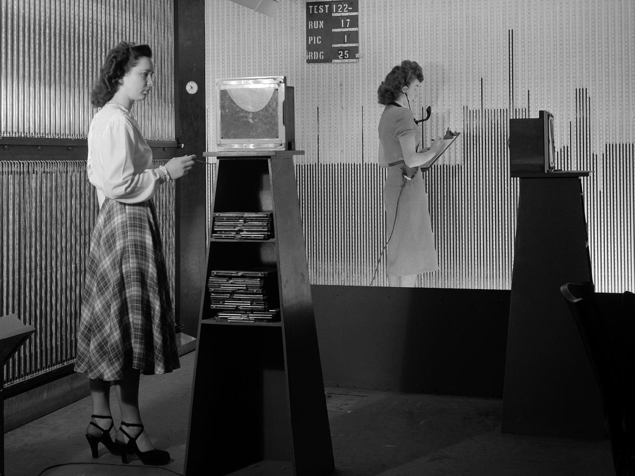
Female computers at the National Advisory Committee for Aeronautics (NACA) Lewis Flight Propulsion Laboratory copy pressure readings from rows of manometers below the 18- by 18-inch Supersonic Wind Tunnel. The computers obtained test data from the manometers and other instruments, made the initial computations, and plotted the information graphically. Based on these computations, the researchers planned their next test or summarized their findings in a report. Manometers were mercury-filled glass tubes that were used to indicate different pressure levels from inside the test facility or from the test article. Manometers look and function very similarly to thermometers. Dozens of pressure sensing instruments were installed for each test. Each was connected to a manometer tube located inside the control room. The mercury inside the manometer rose and fell with the pressure levels. The dark mercury can be seen in this photograph at different levels within the tubes. Since this activity was dynamic, it was necessary to note the levels at given points during the test. This was done using both computer notations and photography.
6x6 wind tunnel test on the effects of wing sweep.
NACA Ames Research Center's 6x6ft Supersonic Wind Tunnel compressor, showing rotor blades
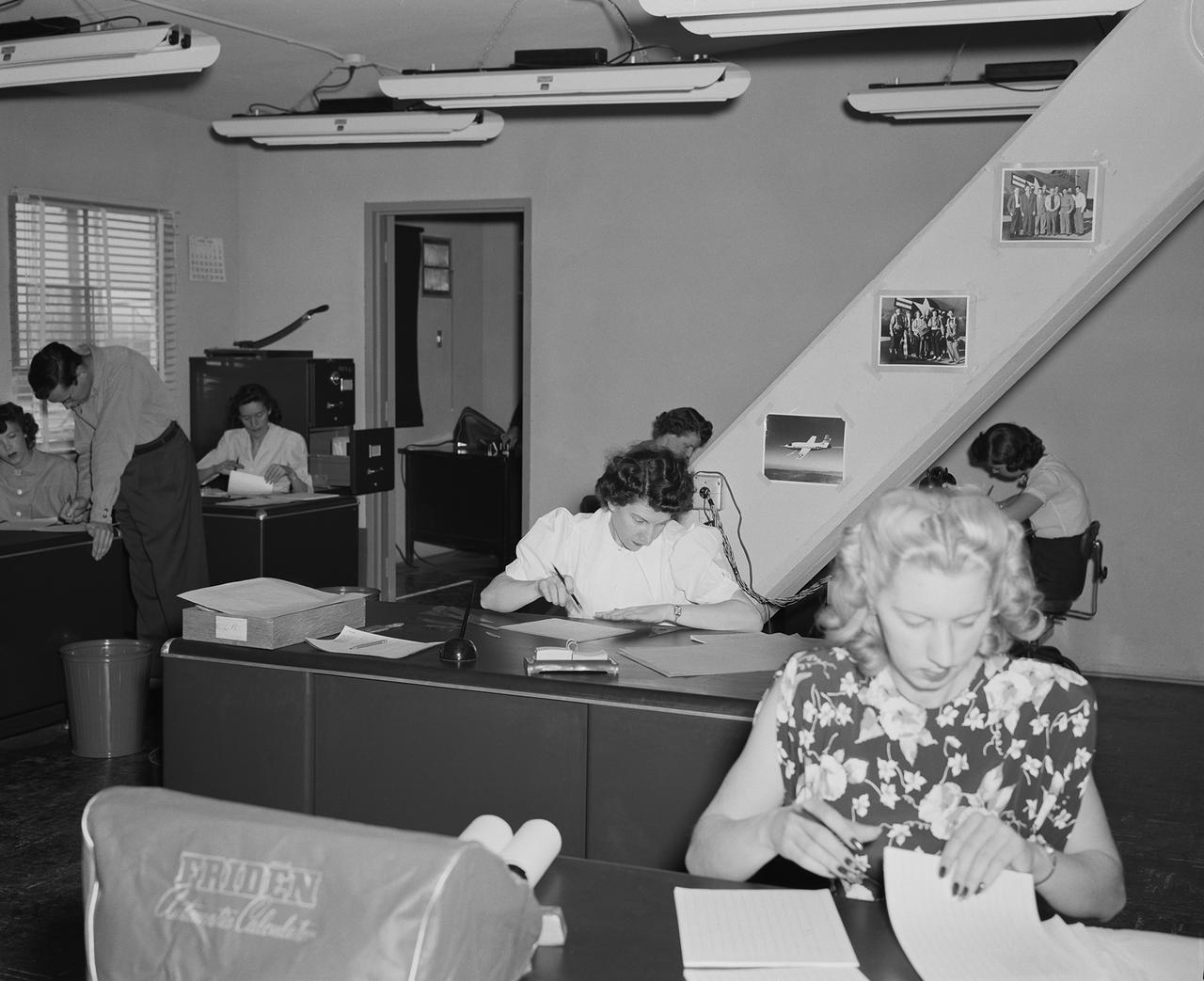
NACA women computers had degrees in mathematics or taught math before they were hired. They reduced film data and plotted it for the engineers.
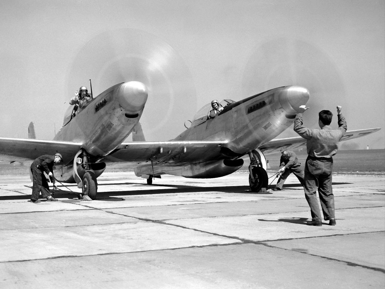
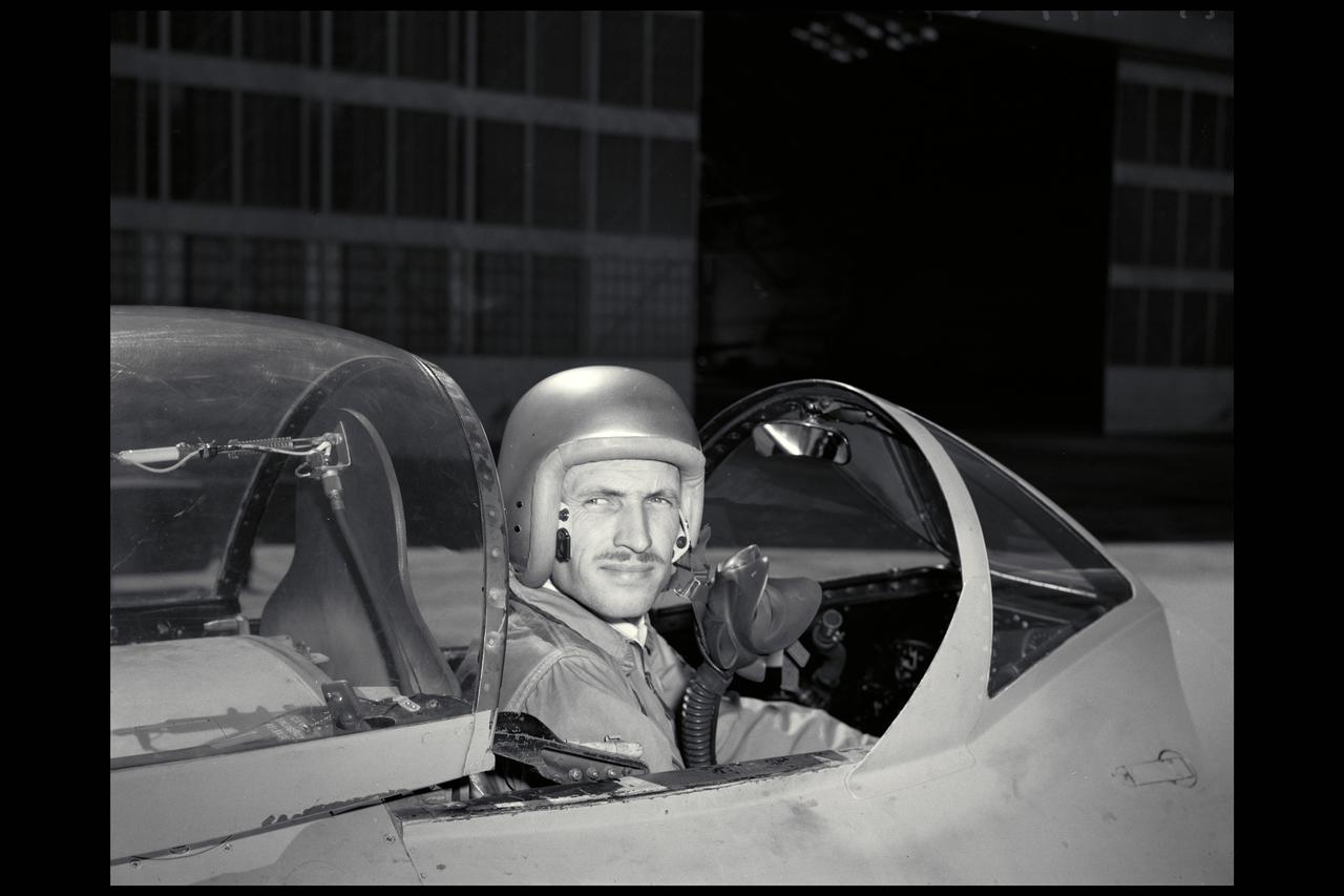
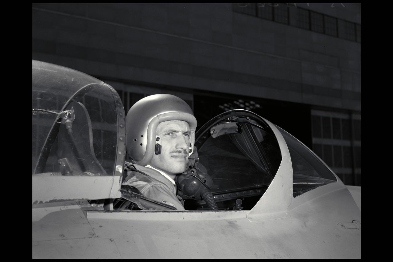
Pilot William Swann, right cockpit, prepares the North American XF-82 Twin Mustang for flight at the National Advisory Committee for Aeronautics (NACA) Lewis Flight Propulsion Laboratory. The aircraft was one of only two prototypes built by North American in October 1945 and powered by Packard Merlin V-1650 piston engines. Over 270 of the F-82 long-distance pursuit fighters were produced during the 1940s. The Mustang’s unique two-pilot configuration allowed one pilot to rest during the long missions and thus be ready for action upon arrival. The NACA took possession of this XF-82 in October 1947. NACA Lewis used the XF-82 as a test bed for ramjet flight tests. Ramjets are continually burning tubes that use the compressed atmospheric air to produce thrust. Ramjets are extremely efficient at high speeds, but rely on some sort of booster to attain that high speed. NACA Lewis undertook an extensive ramjet program in the 1940s that included combustion studies in the Altitude Wind Tunnel, a number of flight tests, and missile drops from aircraft. The 16-inch diameter ramjet missile was fixed to the XF-82 Mustang’s wing and dropped from high altitudes off of Wallops Island. The tests determined the ramjet’s performance and operational characteristics in the transonic range.

Body Mounted on RF-61-C Airplane in flight Note: publiched in NASA SP Flight research at Ames; 57 Years of Development & Validation of Aeronautical Technology ' Transonic Model Testing' - fig. 12

Reeves Electronic analog computer (REAC), Ames' first electronic computing machine, was acquired in 1949 to perform control simulation analysis.
Portrait of Floyd L. Thompson NASA Langley Center Director from 1960 to 1968. Died in 1976
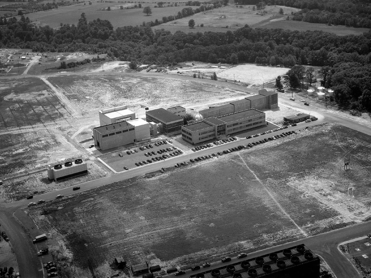
Aerial view of the 8- by 6-Foot Supersonic Wind Tunnel in its original configuration at the National Advisory Committee for Aeronautics (NACA) Lewis Flight Propulsion Laboratory. The 8- by 6 was the laboratory’s first large supersonic wind tunnel. It was also the NACA’s most powerful supersonic tunnel, and its first facility capable of running an engine at supersonic speeds. The 8- by 6-foot tunnel has been used to study inlets and exit nozzles, fuel injectors, flameholders, exit nozzles, and controls on ramjet and turbojet propulsion systems. The 8- by 6 was originally an open-throat and non-return tunnel. This meant that the supersonic air flow was blown through the test section and out the other end into the atmosphere. In this photograph, the three drive motors in the structure at the left supplied power to the seven-stage axial-flow compressor in the light-colored structure. The air flow passed through flexible walls which were bent to create the desired speed. The test article was located in the 8- by 6-foot stainless steel test section located inside the steel pressure chamber at the center of this photograph. The tunnel dimensions were then gradually increased to slow the air flow before it exited into the atmosphere. The large two-story building in front of the tunnel was used as office space for the researchers.
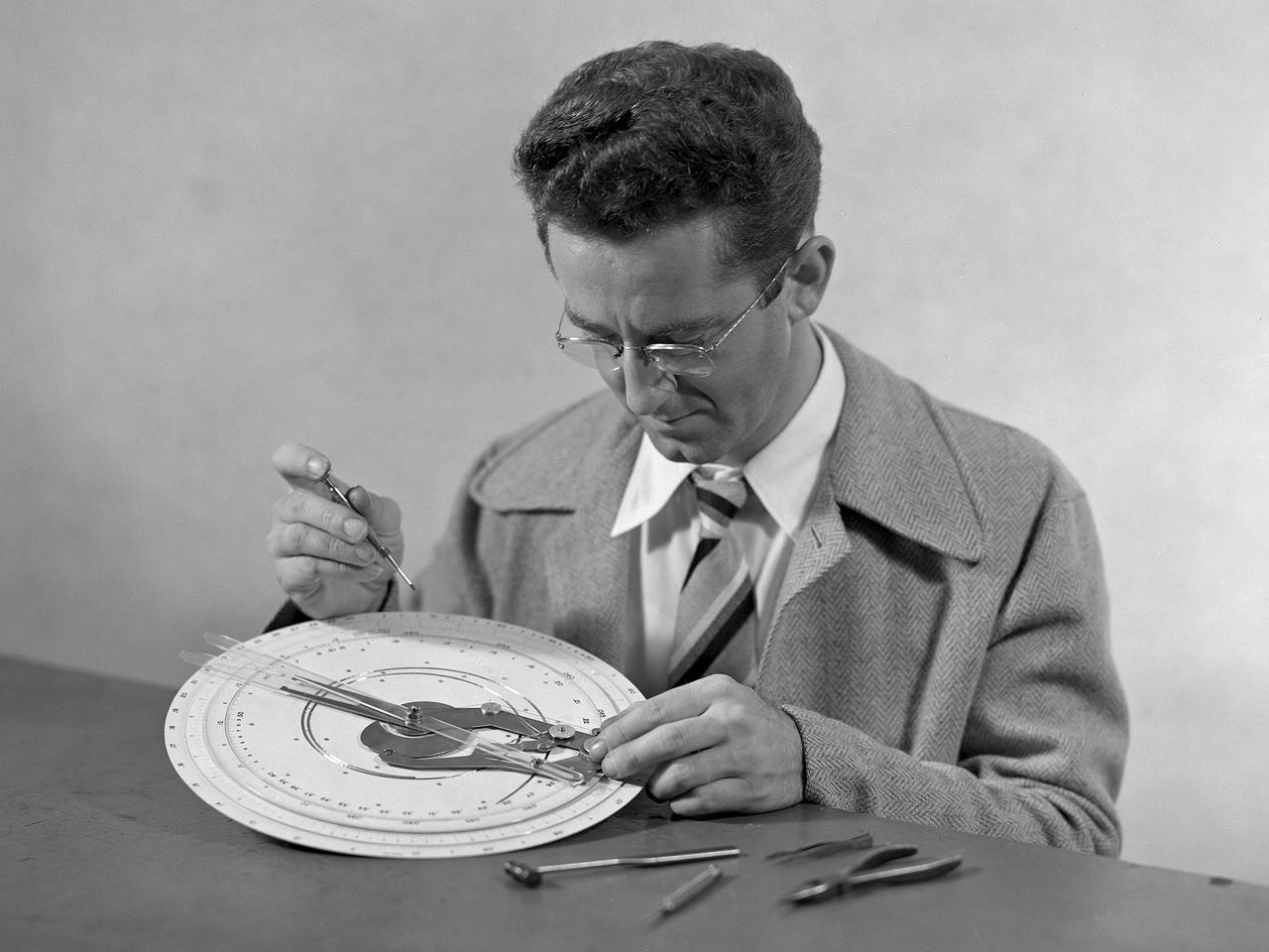
Technician at work adjusting an unidentified mechanical computing device.
NACA PHOTOGRAPHER George Cooper, Ames Test Pilot
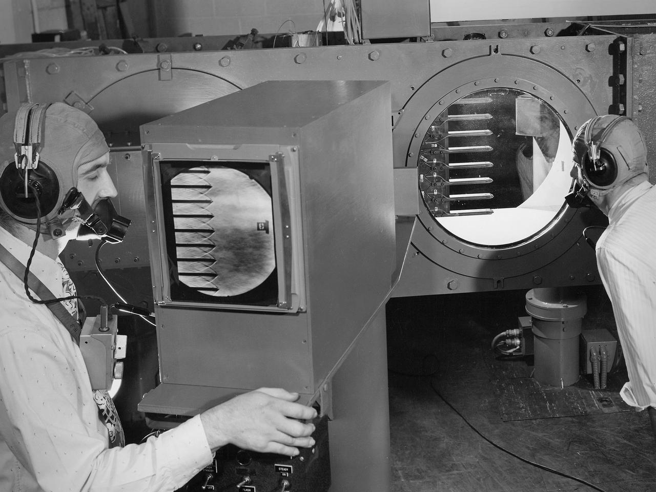
Engineers calibrate one of three small supersonic wind tunnels that were collectively referred to as the “Stack Tunnels” at the National Advisory Committee for Aeronautics (NACA) Lewis Flight Propulsion Laboratory. In late 1945 NACA Lewis reorganized its staff and began constructing a new wave of facilities to address high-speed flight and the turbojet and rocket technologies that emerged during World War II. While design work began on what would eventually become the 8- by 6-Foot Supersonic Wind Tunnel, NACA Lewis quickly built several small supersonic tunnels. These small facilities utilized the Altitude Wind Tunnel’s massive air handling equipment. Three of the small tunnels were built vertically on top of each other and thus were known as the Stack Tunnels. The first of the Stack Tunnels was an 18- by 18-inch tunnel that began operating in August 1945 at speeds up to Mach 1.91. The second tunnel, whose 24- by 24-inch test section is shown here, was added in 1949. It could generate air flows up to Mach 3.96. A third tunnel with an 18- by 18-inch test section began operating in 1951 with speeds up to Mach 3.05. The small tunnels were used until the early 1960s to study the aerodynamic characteristics of supersonic inlets and exits. The technician to the left in this photograph is operating a Schlieren camera to view the air flow dynamics inside the 24- by 24-inch test section. The technician on the right is viewing the pronged test article through the circular window. They are calibrating the tunnel and its equipment to prepare for the initial test runs.

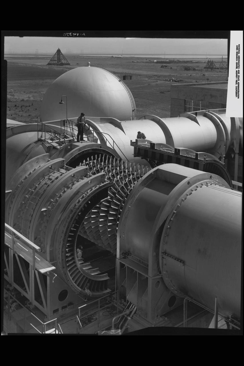
A technician at the National Advisory Committee for Aeronautics (NACA) Lewis Flight Propulsion Laboratory examines one of the massive axial-flow compressor stages that created the high-speed air flow through the 8- by 6-Foot Supersonic Wind Tunnel. The tunnel’s first run was on April 3, 1949, just over a week before this photograph was taken. The 8- by 6 was the laboratory’s first large supersonic wind tunnel and the NACA’s largest supersonic tunnel at the time. The 8- by 6-foot tunnel was originally an open-throat non-return tunnel. The supersonic air flow was blown through the tubular facility and expelled out the other end into the atmosphere with a roar. Complaints from the local community led to the addition of a muffler at the tunnel exit in 1956 and the eventual addition of a return leg. The return leg allowed the tunnel to be operated as either an open system with large doors venting directly to the atmosphere for propulsion system tests or as a closed loop for aerodynamic tests. The air flow was generated by a large seven-stage axial-flow compressor, seen in this photograph, that was powered by three electric motors with a combined 87,000 horsepower. The system required 36,000 kilowatts of power per hour to generate wind velocities of Mach 1.5, and 72,000 kilowatts per hour for Mach 2.0.
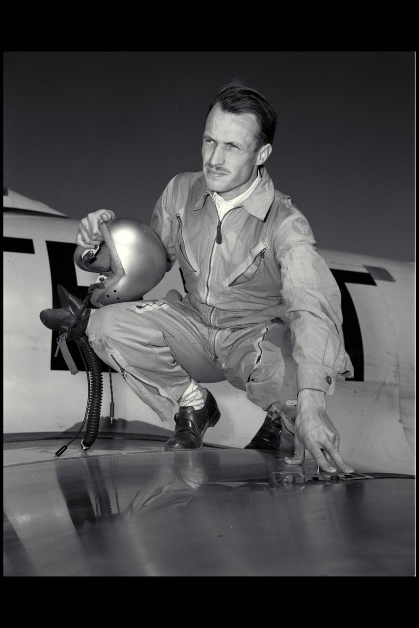
George E. Cooper; Ames Test Pilot
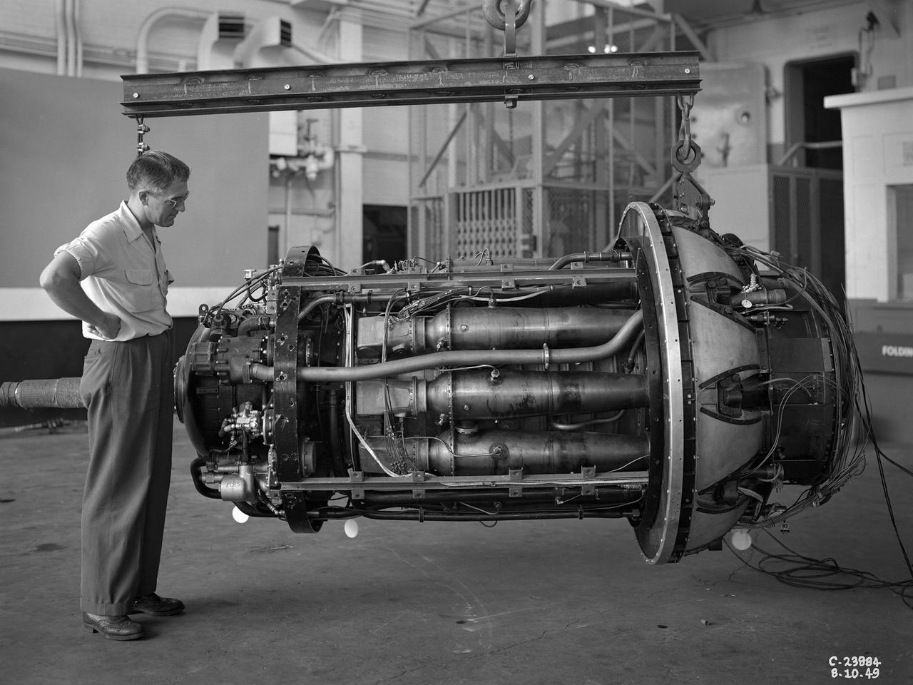
A 3670-horsepower Armstrong-Siddeley Python turboprop being prepared for tests in the Altitude Wind Tunnel at the National Advisory Committee for Aeronautics (NACA) Lewis Flight Propulsion Laboratory. In 1947 Lewis researcher Walter Olsen led a group of representatives from the military, industry, and the NACA on a fact finding mission to investigate the technological progress of British turbojet manufacturers. Afterwards several British engines, including the Python, were brought to Cleveland for testing in Lewis’s altitude facilities. The Python was a 14-stage axial-flow compressor turboprop with a fixed-area nozzle and contra-rotating propellers. Early turboprops combined the turbojet and piston engine technologies. They could move large quantities of air so required less engine speed and thus less fuel. This was very appealing to the military for some applications. The military asked the NACA to compare the Python’s performance at sea to that at high altitudes. The NACA researchers studied the Python in the Altitude Wind Tunnel from July 1949 through January 1950. It was the first time the tunnel was used to study an engine with the sole purpose of learning about, not improving it. They analyzed the engine’s dynamic response using a frequency response method at altitudes between 10,000 to 30,000 feet. Lewis researchers found that they could predict the dynamic response characteristics at any altitude from the data obtained from any other specific altitude. This portion of the testing was completed during a single test run.