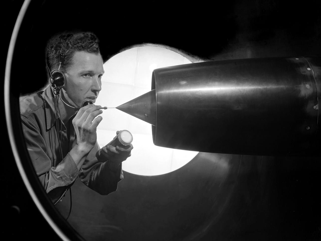
A technician at the National Advisory Committee for Aeronautics (NACA) Lewis Flight Propulsion Laboratory cleans the pitot tube on a 16-inch diameter ramjet in the 8- by 6-Foot Supersonic Wind Tunnel. Pitot tubes are a measurement device used to determine the flow velocity at a specific location in the air stream, not the average velocity of the entire wind stream. NACA Lewis was in the midst of a multi-year program to determine the feasibility of ramjets and design improvements that could be employed for all models. The advantage of the ramjet was its ability to process large volumes of combustion air, resulting in the burning of fuel at the optimal stoichiometric temperatures. This was not possible with turbojets. The higher the Mach number, the more efficient the ramjet operated. The 8- by 6 Supersonic Wind Tunnel had been in operation for just over one year when this photograph was taken. The facility was the NACA’s largest supersonic tunnel and the only facility capable of running an engine at supersonic speeds. The 8- by 6 tunnel was also equipped with a Schlieren camera system that captured the air flow gradient as it passes over the test setup. The ramjet tests in the 8- by 6 tunnel complemented the NACA Lewis investigations using aircraft, the Altitude Wind Tunnel and smaller supersonic tunnels. Researchers studied the ramjet’s performance at different speeds and varying angles -of -attack.
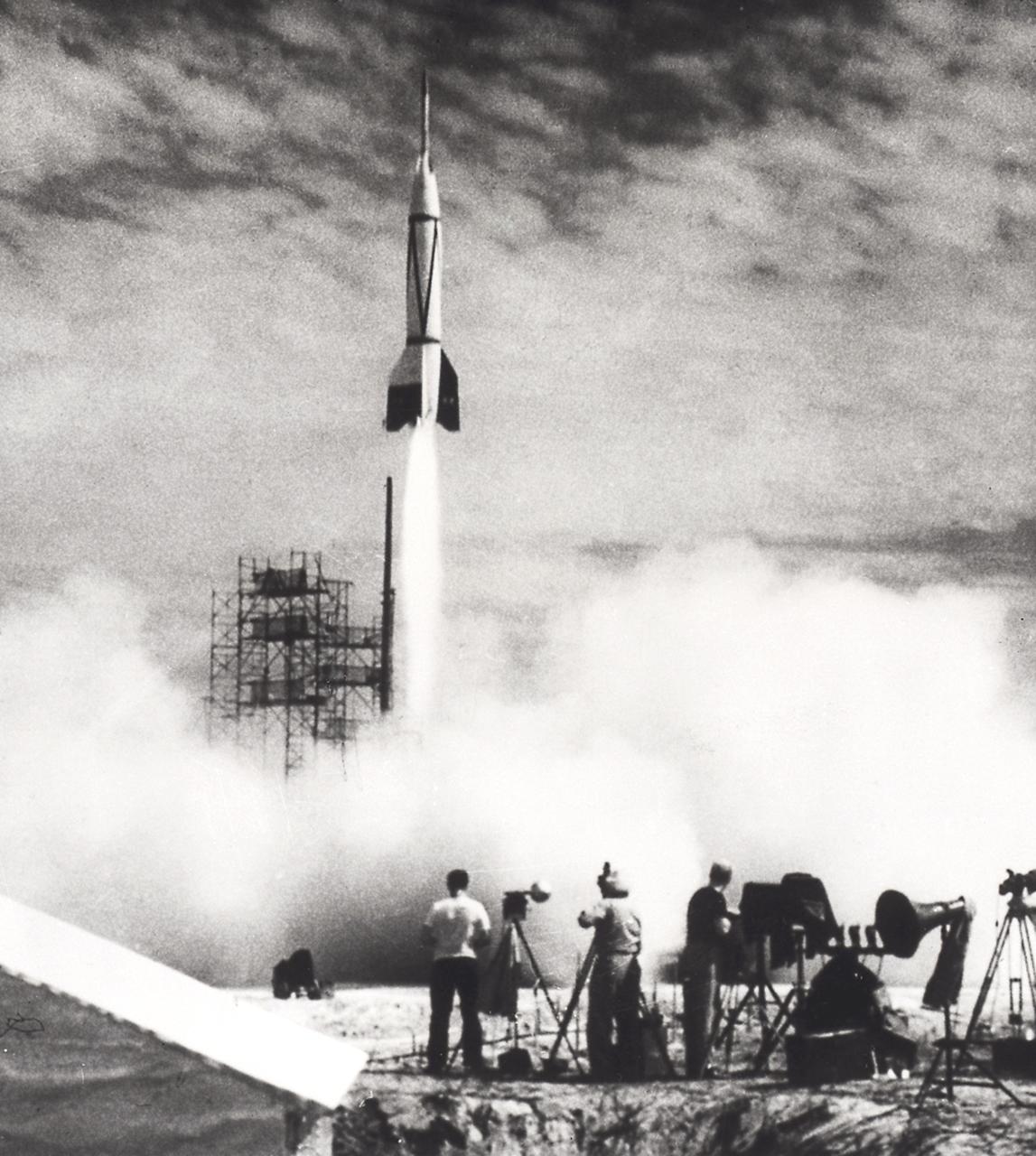
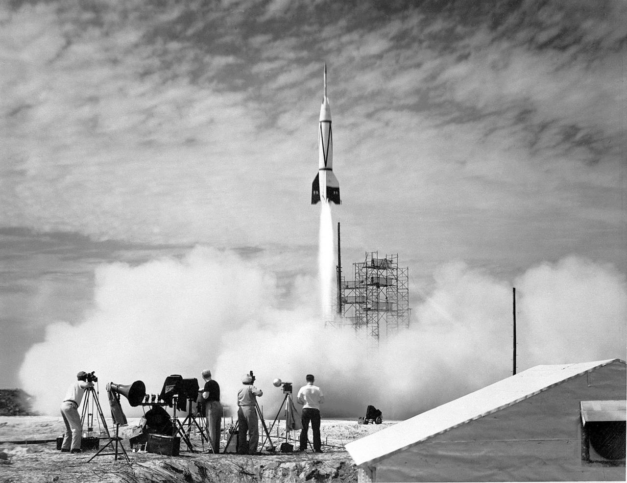
Bumper Wac liftoff at the Long Range Proving Ground located at Cape Canaveral, Florida. At White Sands, New Mexico, the German rocket team experimented with a two-stage rocket called Bumper Wac, which intended to provide data for upper atmospheric research. On February 24, 1950, the Bumper, which employed a V-2 as the first stage with a Wac Corporal upper stage, obtained a peak altitude of more than 240 miles.
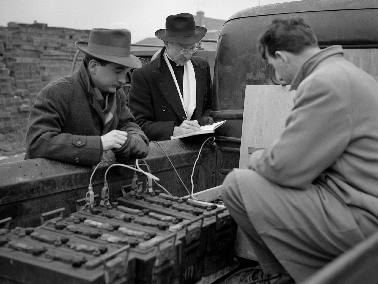
Reverend Henry Birkenhauer and E.F. Carome measure ground vibrations on West 220th Street caused by the operation of the 8- by 6-Foot Supersonic Wind Tunnel at the National Advisory Committee for Aeronautics (NACA) Lewis Flight Propulsion Laboratory. The 8- by 6 was the laboratory’s first large supersonic wind tunnel. It was also the NACA’s most powerful supersonic tunnel, and the NACA’s first facility capable of running an engine at supersonic speeds. The 8- by 6 was originally an open-throat and non-return tunnel. This meant that the supersonic air flow was blown through the test section and out the other end into the atmosphere. Complaints from the local community led to the installation of a muffler at the tunnel exit and the eventual addition of a return leg. Reverend Brikenhauer, a seismologist, and Carome, an electrical technician were brought in from John Carroll University to take vibration measurements during the 8- by 6 tunnel’s first run with a supersonic engine. They found that the majority of the vibrations came from the air and not the ground. The tunnel’s original muffler offered some relief during the facility checkout runs, but it proved inadequate during the operation of an engine in the test section. Tunnel operation was suspended until a new muffler was designed and installed. The NACA researchers, however, were pleased with the tunnel’s operation. They claimed it was the first time a jet engine was operated in an airflow faster than Mach 2.
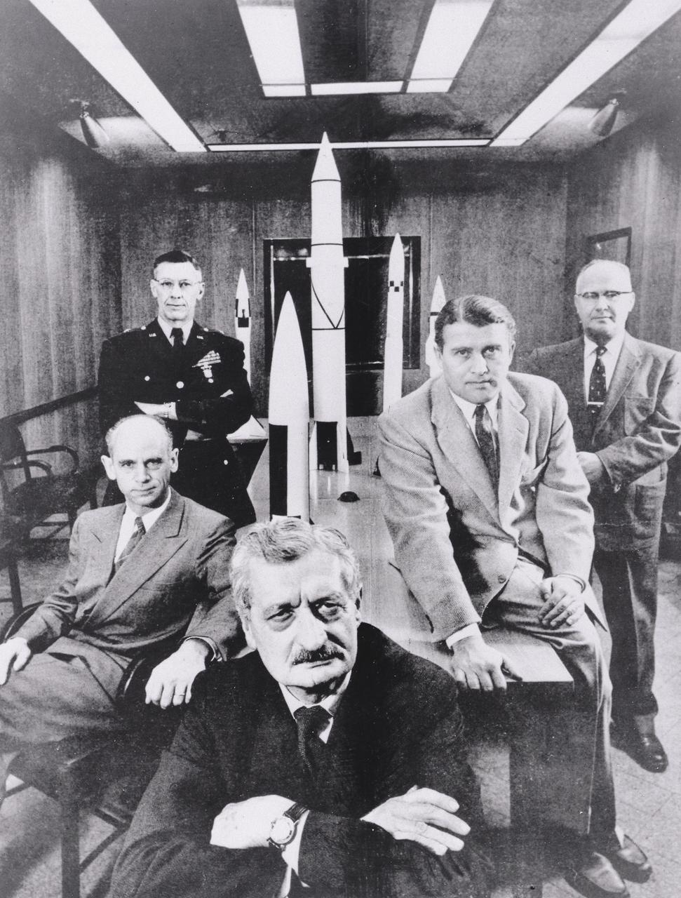
Five pioneers pose with scale models of their missiles they created in the 1950s. From left to right: Dr. Ernst Stuhlinger, a member of the original German rocket team who directed the Research Projects Office, Army Ballistic Missile Agency (ABMA); Major General Holger Toftoy, who consolidated U.S. missile and rocketry development; Professor Herman Oberth, a rocket pioneer and Dr. von Braun's mentor; Dr. Wernher von Braun, Director, Development Operation Division, ABMA; and Dr. Robert Lusser, who served as assistant director for Reliability Engineering for ABMA. This photographis was taken February 1, 1956 by Hank Walker and appeared in February 27, 1956 issue of Life magazine.
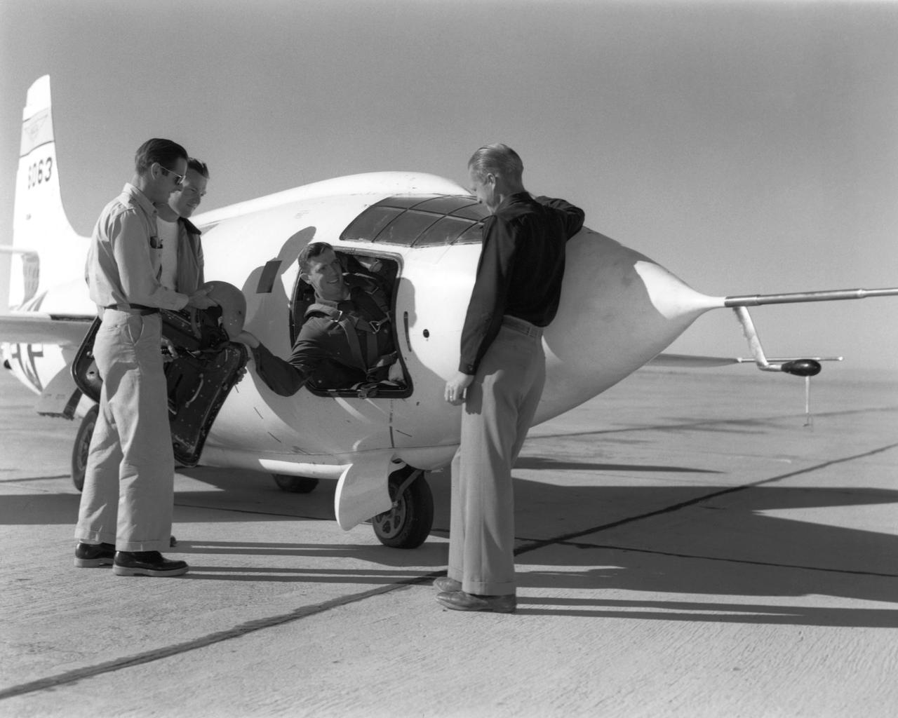
NACA pilot John Griffith hands his flight gear to Dick Payne as crew members Ed Edwards and Clyde Bailey look on.

A mechanic and apprentice work on a wooden impeller in the Fabrication Shop at the NACA Lewis Flight Propulsion Laboratory. The 260-person Fabrication Division created almost all of the equipment and models used at the laboratory. The Technical Services Building, referred to as the “Fab Shop”, contained a number of specialized shops in the 1940s and 1950s. These included a Machine Shop, Sheet Metal Shop, Wood and Pattern Shop, Instrument Shop, Thermocouple Shop, Heat Treating Shop, Metallurgical Laboratory, and Fabrication Office. The Machine Shop fabricated research equipment not commercially available. During World War II these technicians produced high-speed cameras for combustion research, impellers and other supercharger components, and key equipment for the lab’s first supersonic wind tunnel. The Wood and Pattern Shop created everything from control panels and cabinets to aircraft model molds for sheet metal work. The Sheet Metal Shop had the ability to work with 0.01 to 4-inches thick steel plates. The Instrument Shop specialized in miniature parts and instrumentation, while the Thermocouple Shop standardized the installation of pitot tubes and thermocouples. The Metallurgical Laboratory contained a control lab for the Heat Treating Shop and a service lab for the NACA Lewis research divisions. The Heat Treating Shop heated metal parts to optimize their physical properties and contained a Precision Castings Foundry to manufacture equipment made of heat resisting alloys.

Supersonic Free flight Wind tunnel model construction and firing techniques; separation of model and finger type sabot
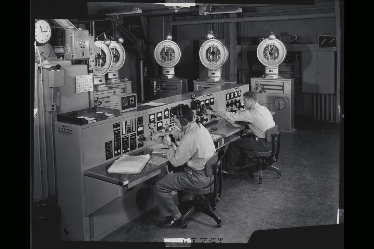
40x80 wind tunnel manometers control room at NACA's Ames Research Center. Control panel (called the bench board) showing five of the seven scale heads which measured the forces on the model (ie. Lift, drag, side force etc.)
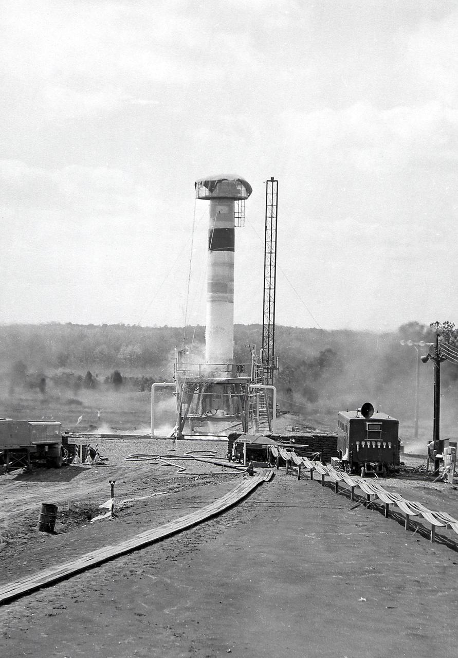
Test firing of a Redstone Missile at Redstone Test Stand in the early 1950's. The Redstone was a high-accuracy, liquid-propelled, surface-to-surface missile developed by the von Braun Team under the management of the U.S. Army. The Redstone was the first major rocket development program in the United States.
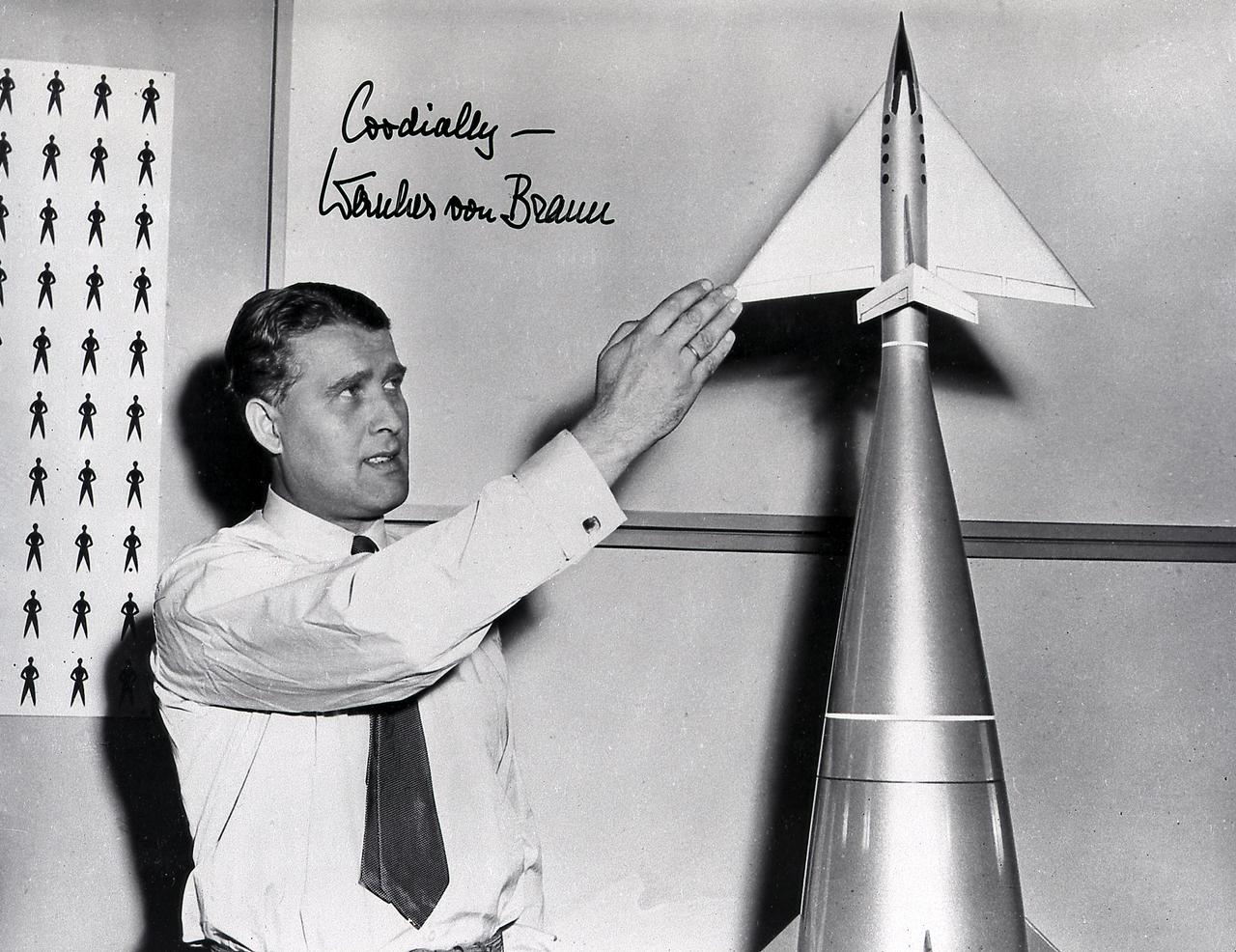
Dr. von Braun stands beside a model of the upper stage (Earth-returnable stage) of the three-stage launch vehicle built for the series of the motion picture productions of space flight produced by Walt Disney in the mid-1950's.
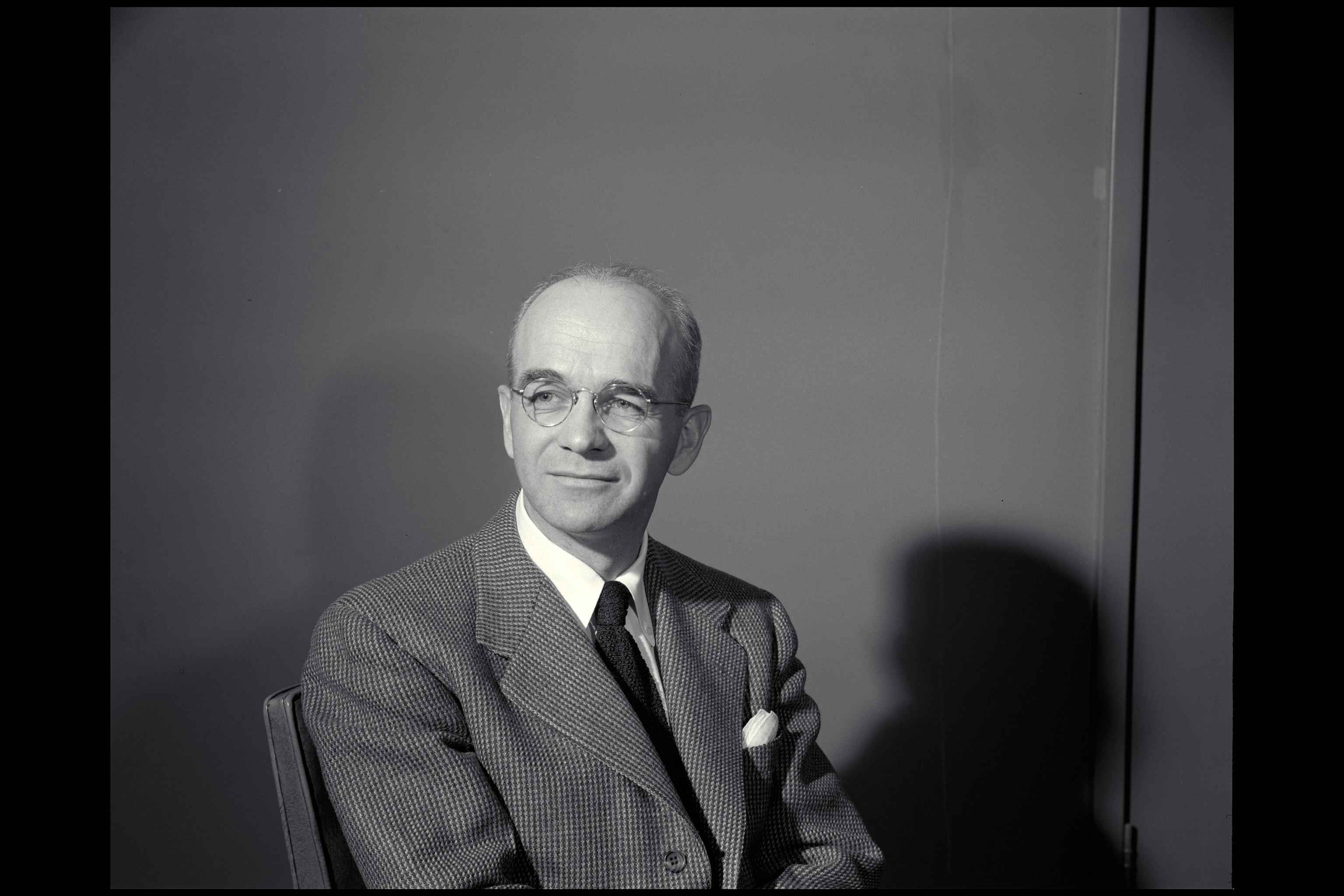
NACA photographer Portrait: Russell Robinson

This photograph shows the installation of a Mercury capsule and escape system on top of a booster prior to test firing of the Mercury-Redstone at Marshall Space Flight Center's (MSFC's) Redstone Test Stand. Assembled by MSFC, the Mercury-Redstone was designed to place a marned space capsule in orbital flight around the Earth and recover both safely.
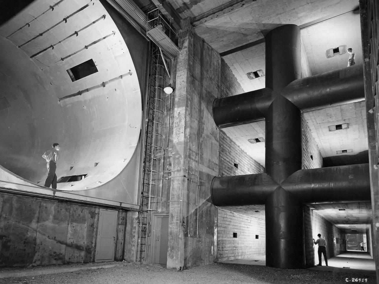
The 8- by 6-Foot Supersonic Wind Tunnel at the National Advisory Committee for Aeronautics (NACA) Lewis Flight Propulsion Laboratory was the largest supersonic wind tunnel in the nation at the time and the only one able to test full-scale engines at supersonic speeds. The 8- by 6 was designed as a non-return and open-throat tunnel. A large compressor created the air flow at one end of the tunnel, squeezed the flow to increase its velocity just before the test section, then reduced the velocity, and expelled it into the atmosphere at the other end of the tunnel. This design worked well for initial aerodynamic testing, but the local community was literally rattled by the noise and vibrations when researchers began running engines in the test section in January 1950. The NACA’s most modern wind tunnel was referred to as “an 87,000-horsepower bugle aimed at the heart of Cleveland.” NACA Lewis responded to the complaints by adding an acoustic housing at the end of the tunnel to dampen the noise. The structure included resonator chambers and a reinforced concrete muffler structure. Modifications continued over the years. A return leg was added, and a second test section, 9 -by 15-foot, was incorporated in the return leg in the 1960s. Since its initial operation in 1948, the 8- by 6-foot tunnel has been aggressively used to support the nation's aeronautics and space programs for the military, industry, and academia.
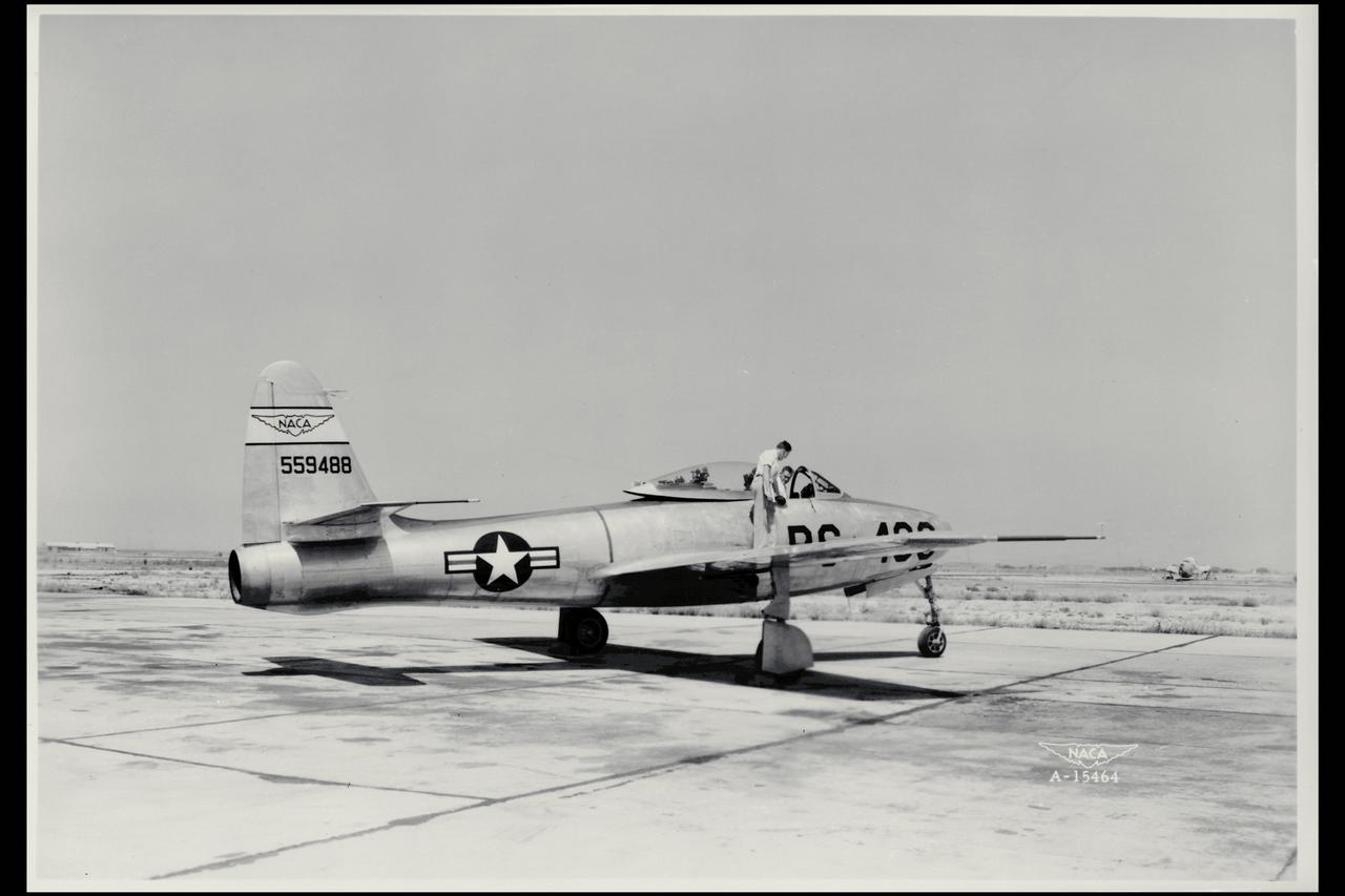
Aileron control; EYF-84 (No. 559488) airplane, differential pressure. The P-84A had a climbing tendency starting at March 0.78.
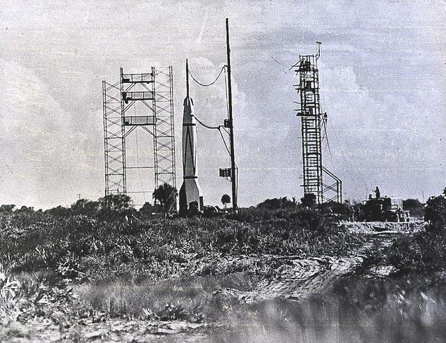
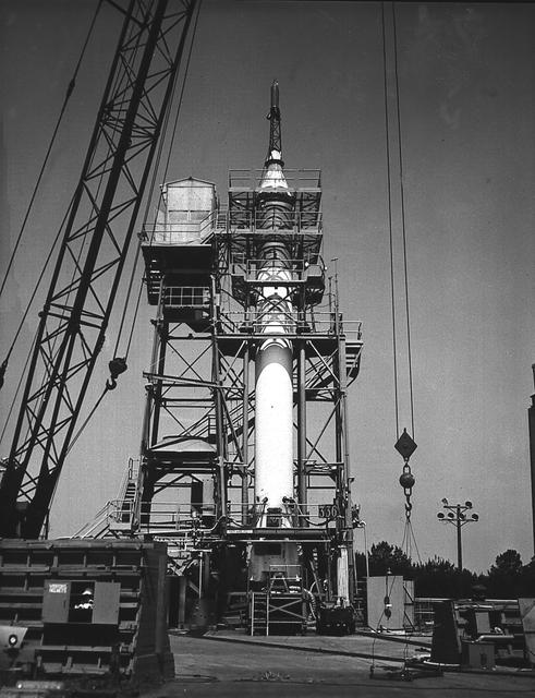
A Bumper Wac, a combination the V-2 rocket with a WAC Corporal upper stage, awaits launch on July 24, 1950. It was the eighth in the Bumper Project and the vehicle reached the altitude of 393 kilometers. The Bumper was built by the German Rocket experts at the White Sands Proving Ground in New Mexico. In 1950, the last two Bumper launches took place in Florida, at the Long Range Proving Ground, located at Cape Canaveral.
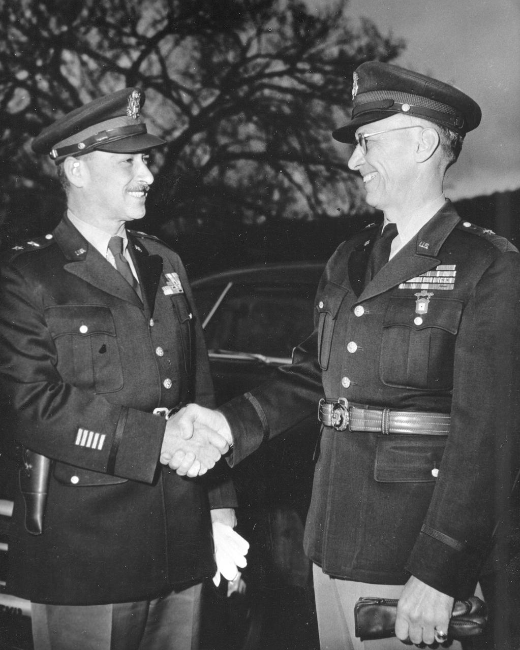
General Medaris, (left) who was a Commander of the Army Ballistic Missile Agency (ABMA) in Redstone Arsenal, Alabama, during 1955 to 1958, shakes hands with Major General Holger Toftoy (right), who consolidated U.S. missile and rocketry development.
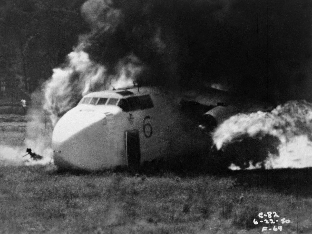
Researchers at the National Advisory Committee for Aeronautics (NACA) Lewis Flight Propulsion Laboratory purposely crash a Fairchild C-82 Packet aircraft to study flame propagation. A rash of passenger aircraft crashes in 1946 and 1947 spurred a White House call for an investigatory board staffed by members of the Civil Aeronautics Board, military, and the NACA. The group addressed fire segregation, extinguishment, and prevention. The NACA established a Subcommittee on Aircraft Fire Prevention in February 1948 to coordinate its efforts. The Lewis team simulated situations in which an aircraft failed to become airborne during takeoff resulting in crashes into embankments and other objects. The Lewis researchers initially used surplus C-46 and C-82 military transport planes. In these situations, the aircraft generally suffered damage to its fuel system and other components, but was structurally survivable. The aircraft were mounted to a rail that ran down a 1700-foot long test runway. The aircraft was secured at the starting point with an anchor pier so it could get its engines up to takeoff speed before launching down the track. Barriers at the end of the runway were designed to simulate a variety of different types of crashes. Telemetry and high-speed cameras were crucial elements in these studies. The preliminary testing phase identified potential ignition sources and analyzed the spread of flammable materials.
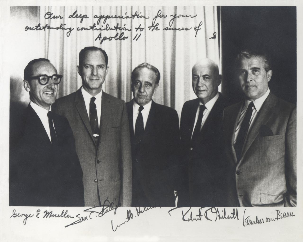
This historical photograph is of the Apollo Space Program Leaders. An inscription appears at the top of the image that states, “Our deep appreciation for your outstanding contribution to the success of Apollo 11”, signed “S”, indicating that it was originally signed by Apollo Program Director General Sam Phillips, pictured second from left. From left to right are; NASA Associate Administrator George Mueller; Phillips; Kurt Debus, Director of the Kennedy Space Center; Robert Gilruth, Director of the Manned Spacecraft Center, later renamed the Johnson Space Center; and Wernher von Braun, Director of the Marshall Space Flight Center.
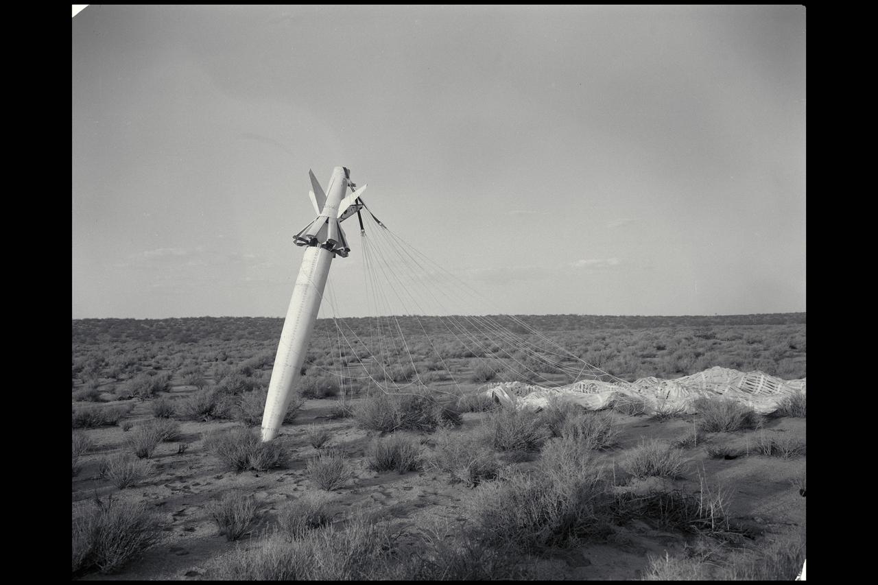
NACA photograpehr Drop 2 SI-2 body in free fall flight (SI-II missile)
KENNEDY SPACE CENTER, FLA. -- The Bumper V-2 is the first missile launched at Cape Canaveral on July 24, 1950.

Researchers at the National Advisory Committee for Aeronautics (NACA) Lewis Flight Propulsion Laboratory conducted an extensive investigation into the composition of clouds and their effect on aircraft icing. The researcher in this photograph is installing cameras on a Beach AT-11 Kansan in order to photograph water droplets during flights through clouds. The twin engine AT-11 was the primary training aircraft for World War II bomber crews. The NACA acquired this aircraft in January 1946, shortly after the end of the war. The NACA Lewis’ icing research during the war focused on the resolution of icing problems for specific military aircraft. In 1947 the laboratory broadened its program and began systematically measuring and categorizing clouds and water droplets. The three main thrusts of the Lewis icing flight research were the development of better instrumentation, the accumulation of data on ice buildup during flight, and the measurement of droplet sizes in clouds. The NACA researchers developed several types of measurement devices for the icing flights, including modified cameras. The National Research Council of Canada experimented with high-speed cameras with a large magnification lens to photograph the droplets suspended in the air. In 1951 NACA Lewis developed and flight tested their own camera with a magnification of 32. The camera, mounted to an external strut, could be used every five seconds as the aircraft reached speeds up to 150 miles per hour. The initial flight tests through cumulus clouds demonstrated that droplet size distribution could be studied.
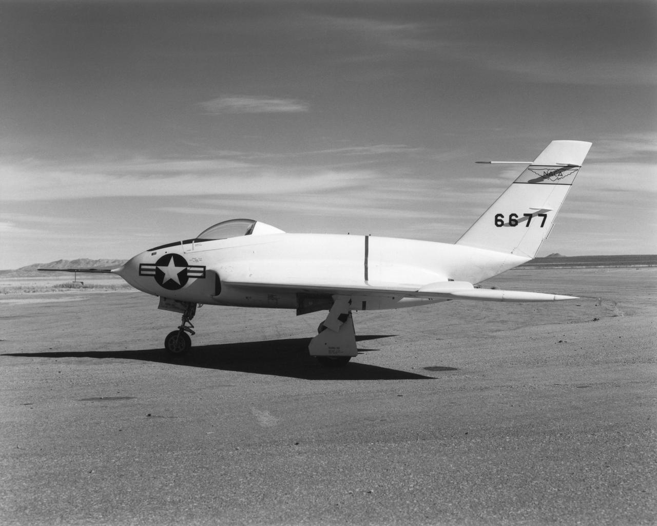
In this 1950 view of the left side of the NACA High-Speed Flight Research Station's X-4 research aircraft, the low swept wing and horizontal taillest design are seen. The X-4 Bantam, a single-place, low swept-wing, semi-tailless aircraft, was designed and built by Northrop Aircraft, Inc. It had no horizontal tail surfaces and its mission was to obtain in-flight data on the stability and control of semi-tailless aircraft at high subsonic speeds.
A Mercury-Redstone launch vehicle awaits test-firing in the Redstone Test Stand during the late 1950s. Between 1953 and 1960, the rocket team at Redstone Arsenal in Huntsville, Alabama performed hundreds of test firings on the Redstone rocket, over 200 on the Mercury-Redstone vehicle configuration alone. It was this configuration which launched America's first two marned space missions, Freedom 7 and Liberty Bell 7,in 1961.
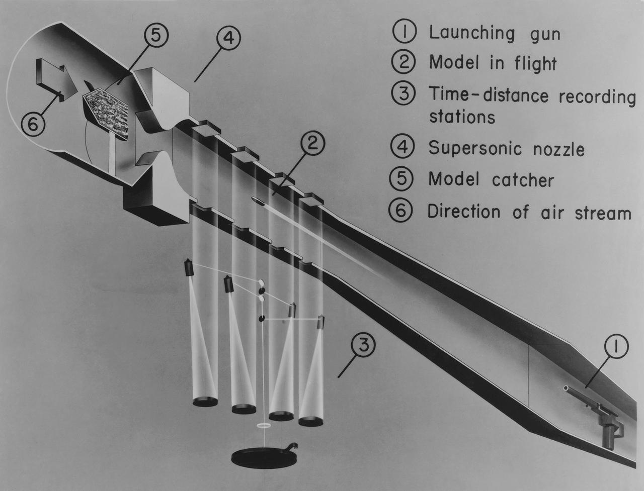
Ames hi-speed research schematic drawing of the Supersonic Free Flight Tunnel (SSFFT)
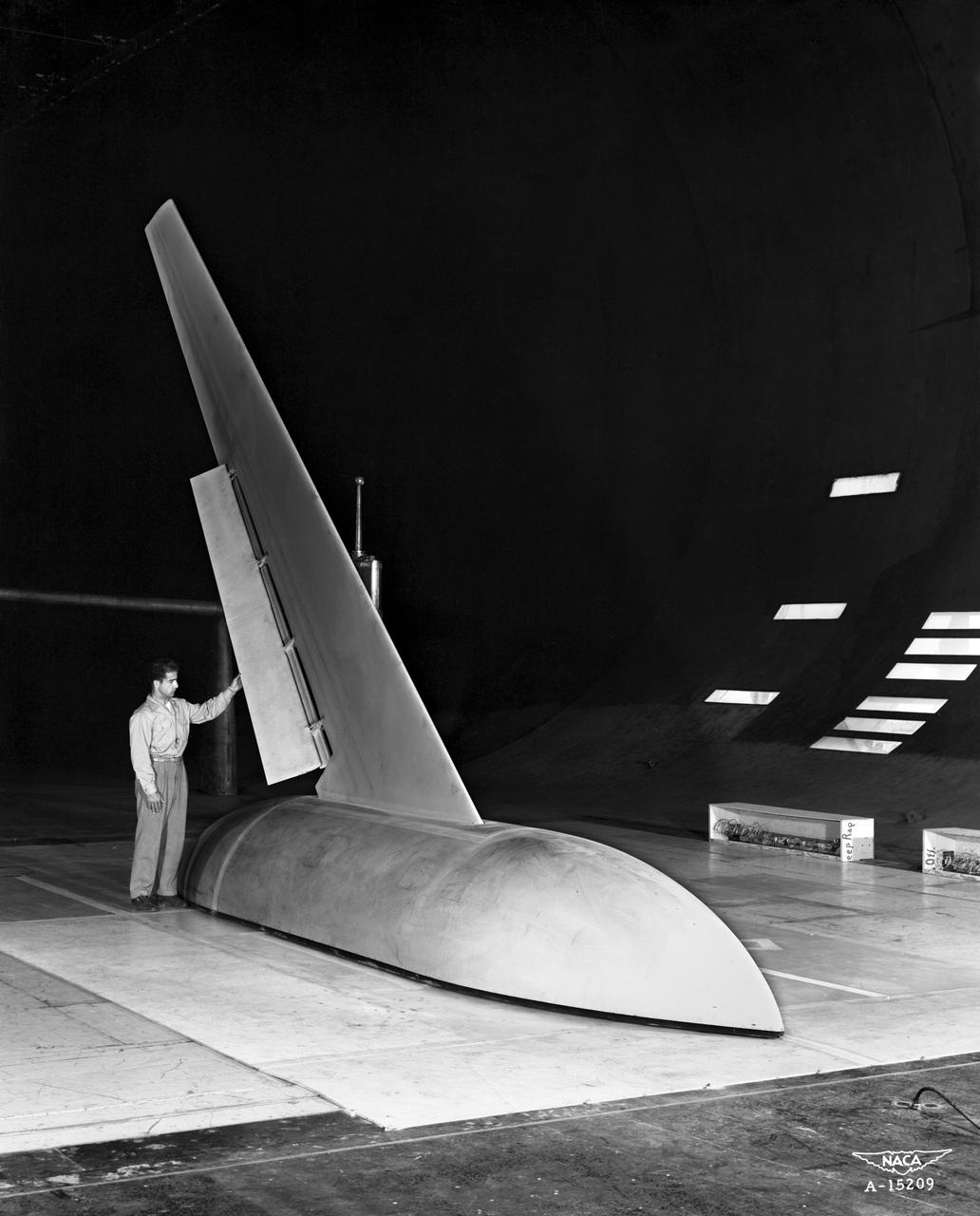
Investigation of High Lift and Stall Control on 45 deg. 3/4 front view Sweptback Cambered and Twisted Wing, in Ames 40x80 foot Wind Tunnel.

NACA photographer Portrait: Russell Robinson
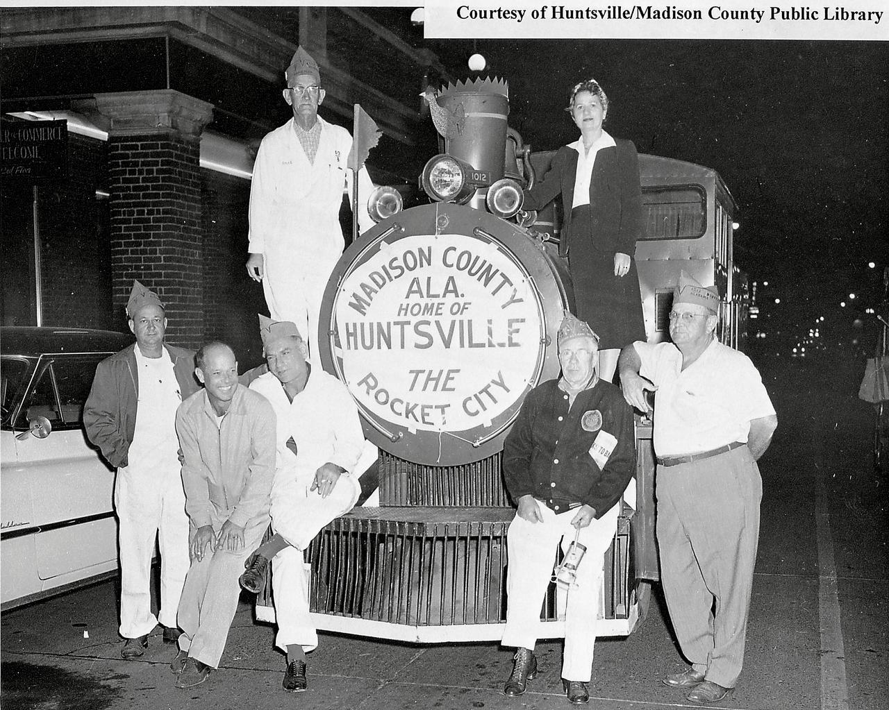
As the nations missile and rocket program began to expand in the 50's, Huntsville, Alabama was the home to Redstone Arsenal and the famous team of rocket experts led by Dr. Wernher Von Braun. Soon Huntsville was called the "Rocket City" as depicted in this photo believed to have been taken in the 1950's in Huntsville, Alabama. (Courtesy of Huntsville/Madison County Public Library)