A female computer at the National Advisory Committee for Aeronautics (NACA) Lewis Flight Propulsion Laboratory with a slide rule and Friden adding machine to make computations. The computer staff was introduced during World War II to relieve short-handed research engineers of some of the tedious computational work. The Computing Section was staffed by “computers,” young female employees, who often worked overnight when most of the tests were run. The computers obtained test data from the manometers and other instruments, made the initial computations, and plotted the data graphically. Researchers then analyzed the data and summarized the findings in a report or made modifications and ran the test again. There were over 400 female employees at the laboratory in 1944, including 100 computers. The use of computers was originally planned only for the duration of the war. The system was so successful that it was extended into the 1960s. The computers and analysts were located in the Altitude Wind Tunnel Shop and Office Building office wing during the 1940s and transferred to the new 8- by 6-Foot Supersonic Wind Tunnel in 1948.

The Bell Aircraft Corporation X-1-2 aircraft on the ramp at NACA High Speed Flight Research Station located on the South Base of Muroc Army Air Field in 1947. The X-1-2 flew until October 23, 1951, completing 74 glide and powered flights with nine different pilots. The aircraft has white paint and the NACA tail band. The black Xs are reference markings for tracking purposes. They were widely used on NACA aircraft in the early 1950s.
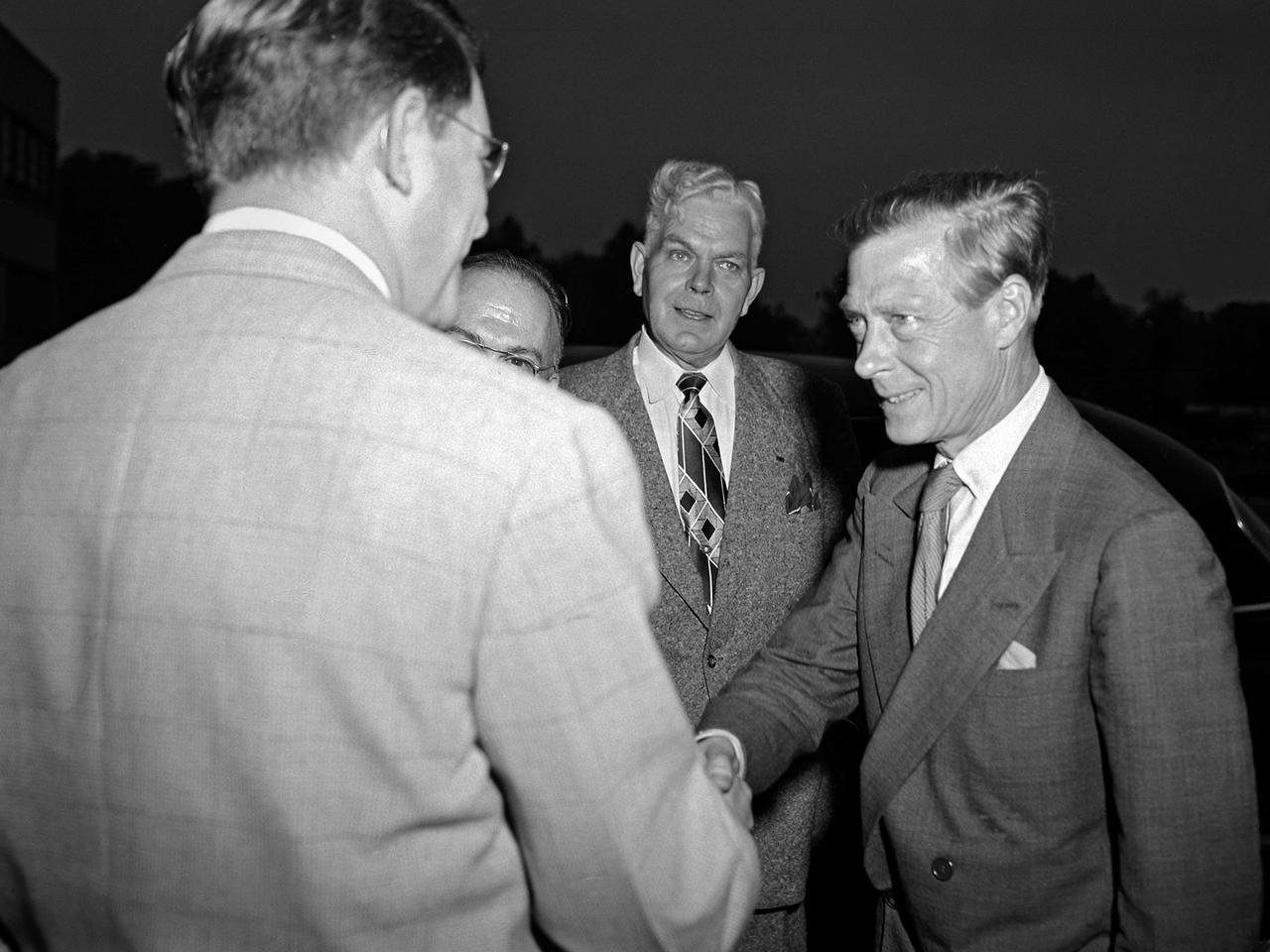
Edward Saxe-Coburg-Gotha, the Duke of Windsor, visits the National Advisory Committee for Aeronautics (NACA) Lewis Flight Propulsion Laboratory in Cleveland, Ohio. He is seen in this photograph shaking hands with Associate Director Abe Silverstein. Lewis Director Ray Sharp is in the background. Cleveland mayor Thomas Burke and other local officials were also on hand to greet Edward. Silverstein led the group on a tour of Lewis’ new 8- by 6-Foot Supersonic Wind Tunnel where the Duke inquired about the operation of the facility’s flexible walls, the types of components tested, and the generation of airflow. The Duke was in town in 1951 to promote his new autobiography, A King’s Story, at the American Booksellers Convention. Edward had assumed the British throne in January 1936, only to renounce the position less than a year later to controversially marry Wallis Simpson. Ongoing concerns over the couple’s relationship to the German government resulted in his World War II assignment to the Bahamas. Edward spent the remainder of his life in France.

Date: Dec 6, 1951 NACA Photographer North American YF-93 with submerged divergent-wall engine-air inlet. Maximum high-speed capability of Mach 1.03 was obtained with afterbrner on. Tests were conducted to compare high-speed performance of the YF-93 NACA-139 airplane with different inlet configurations. (Mar 1953)

An inlet duct lowered into the 20-foot diameter test section of the Altitude Wind Tunnel at the National Advisory Committee for Aeronautics (NACA) Lewis Flight Propulsion Laboratory. Engines and hardware were prepared in the facility’s shop area. The test articles were lifted by a two-rail Shaw box crane through the high-bay and the second-story test chamber before being lowered into the test section. Technicians then spent days or weeks hooking up the supply lines and data recording telemetry. The engines were mounted on wingspans that stretched across the test section. The wingtips attached to the balance frame’s trunnions, which could adjust the angle of attack. The balance frame included six devices that recorded data and controlled the engine. The measurements were visible in banks of manometer boards next to the control room. Photographs recorded the pressure levels in the manometer tubes, and the computing staff manually converted the data into useful measurements. A mechanical pulley system was used to raise and lower the tunnel’s large clamshell lid into place. The lid was sealed into place using hand-turned locks accessible from the viewing platform. The lid had viewing windows above and below the test article, which permitted the filming and visual inspection of the tests.
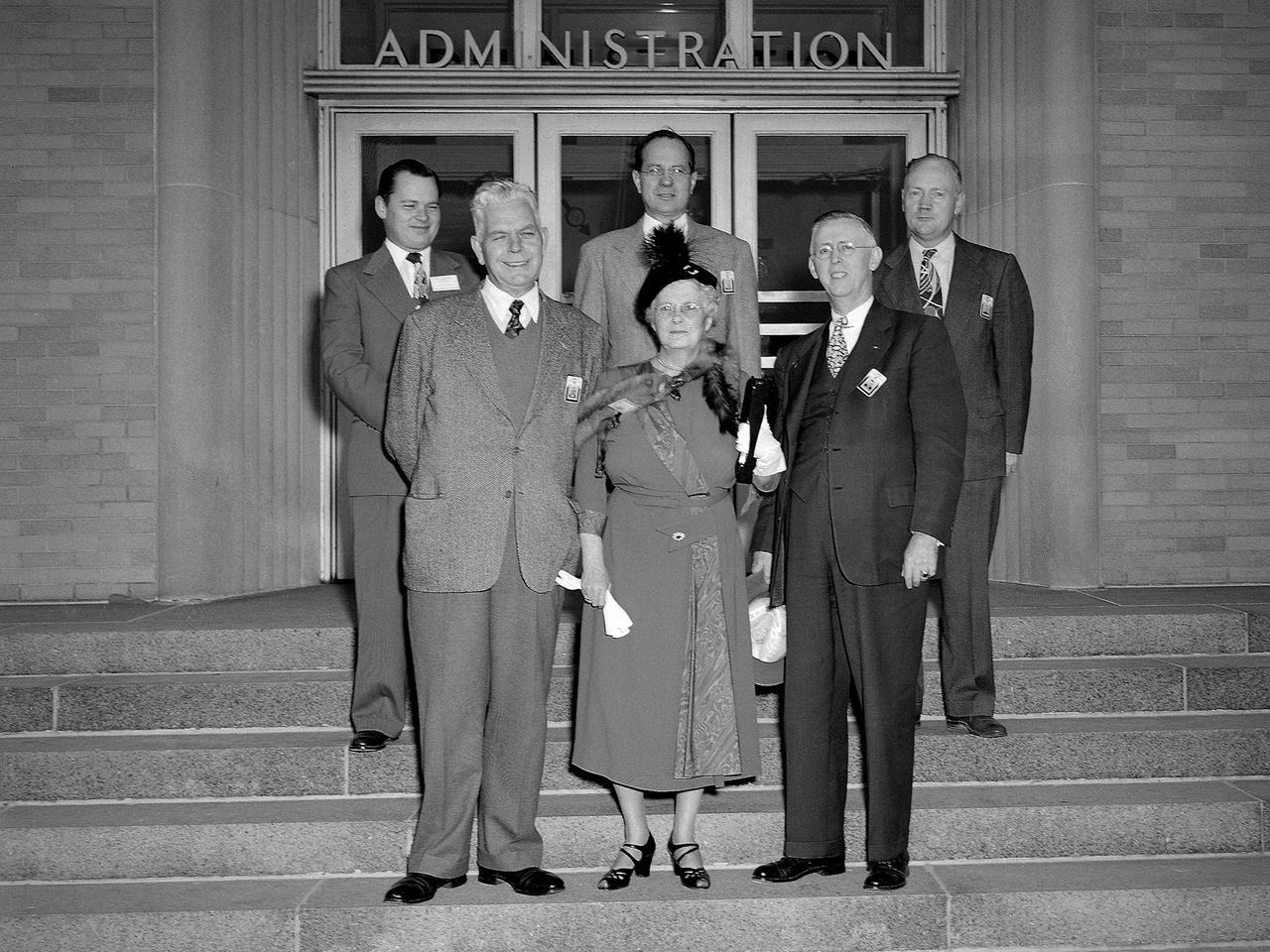
Myrtle Lewis and three of her sons visit the National Advisory Committee for Aeronautics (NACA) Lewis Flight Propulsion Laboratory in Cleveland, Ohio. The Flight Propulsion Research Laboratory was renamed in Lewis’ honor in September 1948. Lewis served as the NACA’s Director of Aeronautical Research for over 20 years. Lewis joined the NACA as Executive Officer in 1919 and was named Director of Aeronautical Research in 1924. In this role Lewis served as the liaison between the Executive Committee and the research laboratories. His most important accomplishment may have been the investigative tours of German research facilities in 1936 and 1939. The visits resulted in the NACA’s physical expansion and the broadening of its scope of research. Lewis did not take a day of leave between the Pearl Harbor attack and the Armistice, but began suffering health problems in 1945. He was forced to retire two years later and passed in July 1948. Front row, left to right: Lewis Director Raymond Sharp, Mrs. Lewis, NACA Executive Secretary John Victory; back row: Executive Officer Robert Sessions, Armand Lewis, Harvey Lewis, and George Lewis II. Harvey and George Lewis II were employed at NACA Lewis in the Instrument Service and Applied Compressor sections, respectively.
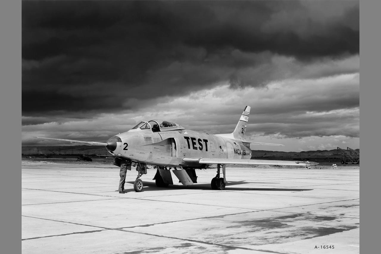
YF-93A (AF48-318 NACA-151) Flight evaluation and comparison of a NACA submerged inlet and a scoop inlet. The YF-93A's were the first aircraft to use flush NACA engine inlets. Note: Used in Flight Research at Ames; 57 Years of Development and Validation of Aeronautical Technology NASA SP-1998-3300 Fig.25
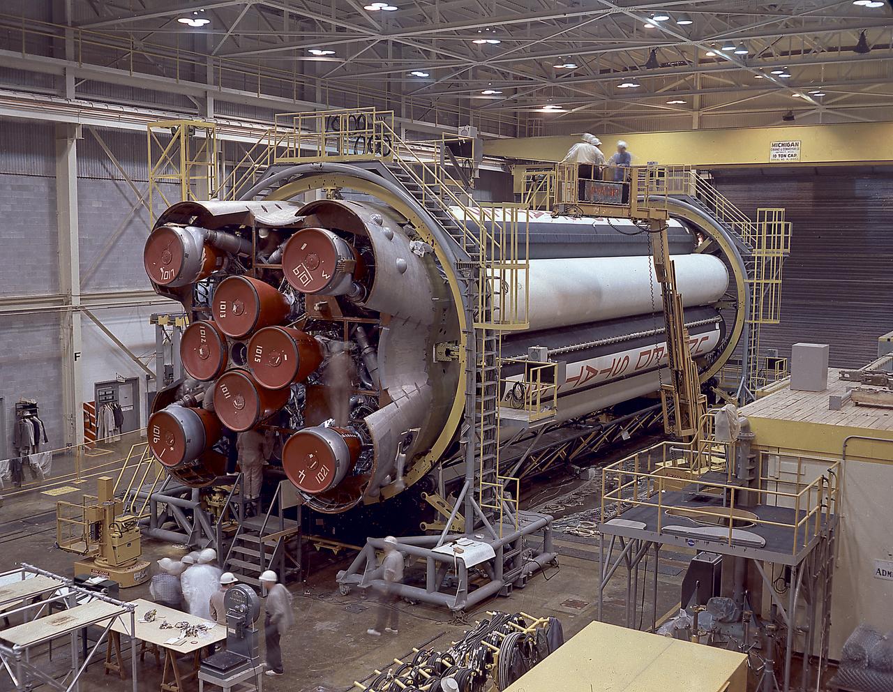
The photograph shows the completed Saturn 1 S-1 stage (booster) during the checkout in the Marshall Space Flight Center, building 4705, January 23, 1961. The Saturn I S-I stage had eight H-1 engines clustered, using liquid oxygen/kerosene-1 (LOX/RP-1) propellants capable of producing a total of 1,500,000 pounds of thrust.
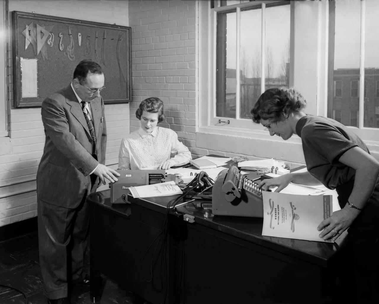
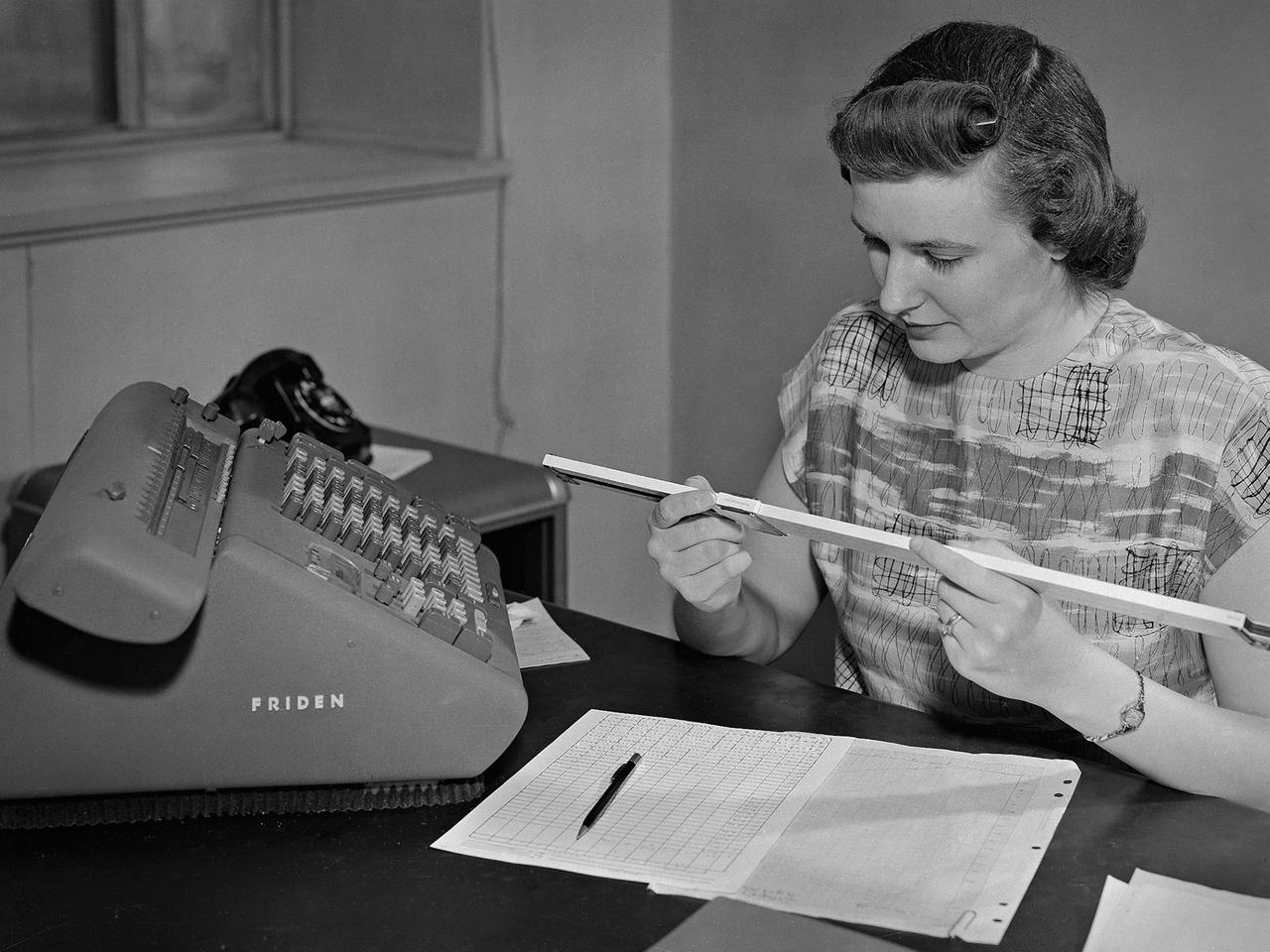
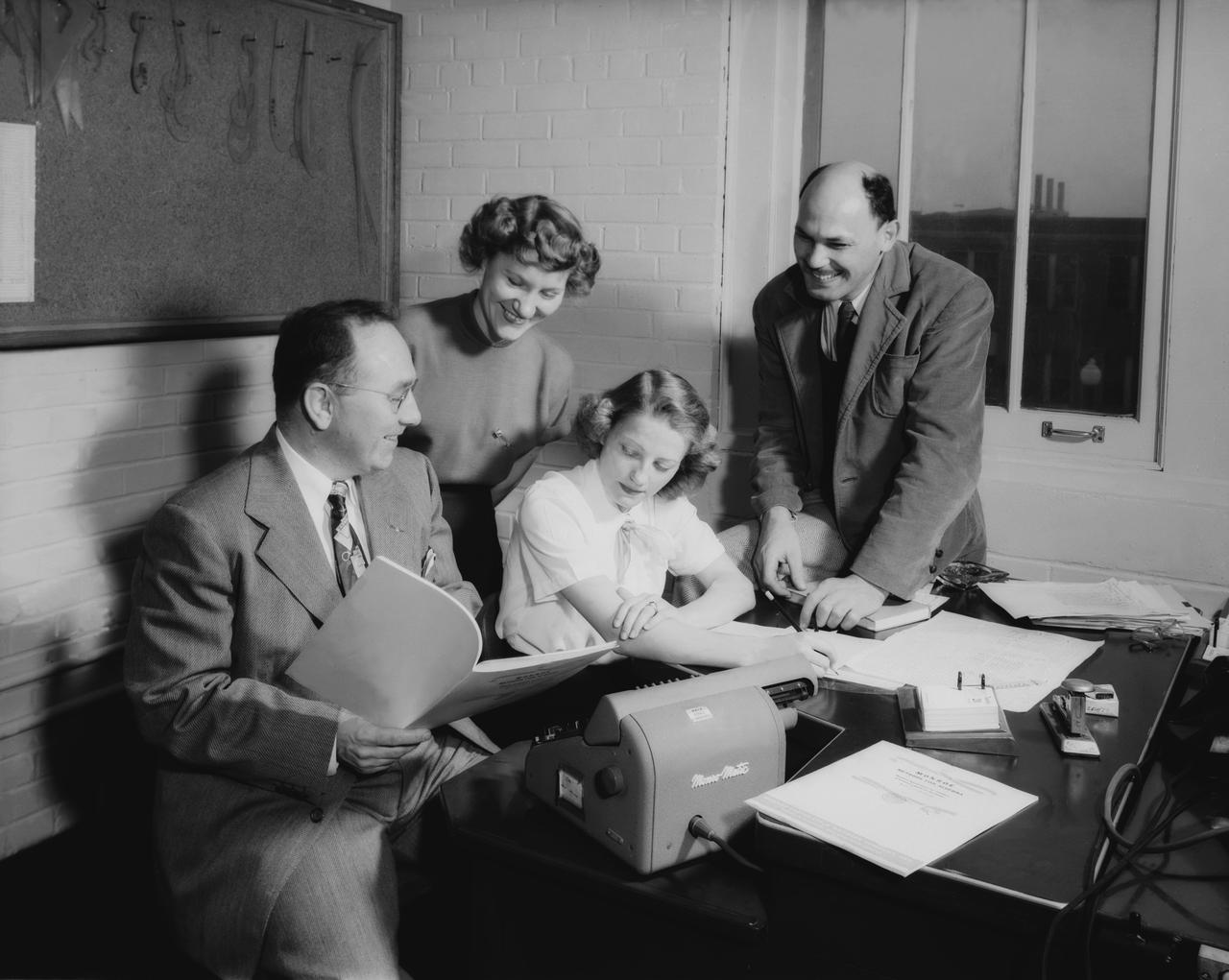
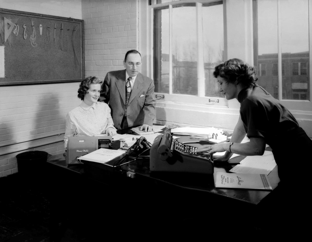
NACA Laboratory Computers Help Compile Handbook: ''Monroe Methods for Algebra, " a new booklet describing short-cuts that can be used in solving frequently-used algebraic formulas with a calculating machine, is undergoing its first trial at the hands of Laboratory computers. Several Monro-matics were purchased recently by NACA. In photo are W.H. Rankins discusses the "Monroe Methods for Algebra" with Gladys Storey (seated) and Ferne Gapcynski, both of 16 foot Hight Speed Tunnel. NACA Air Scoop August 17,1951 Page 4.
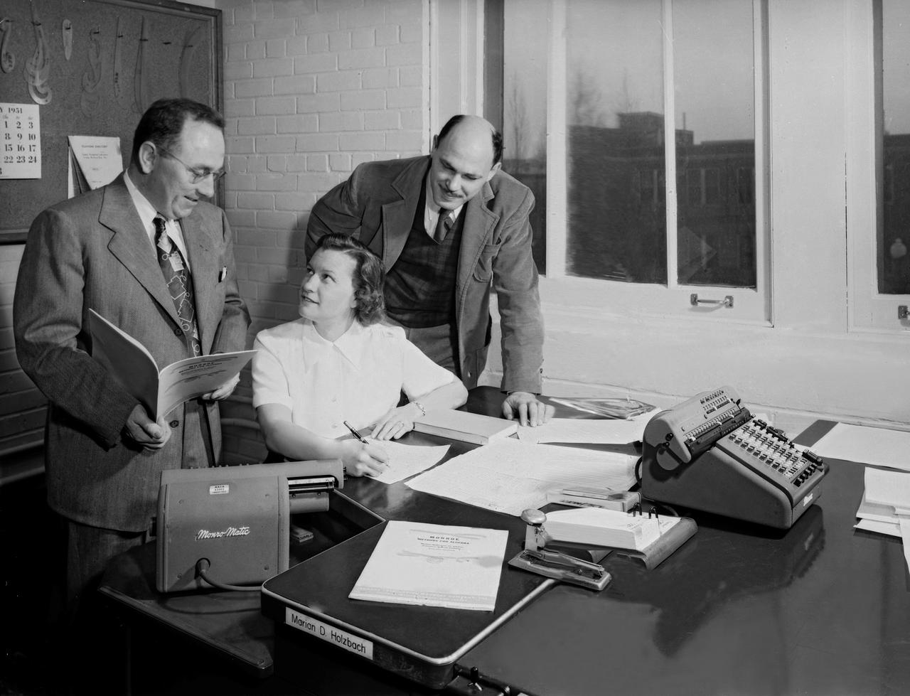
NACA Laboratory Computers Help Compile Handbook: ''Monroe Methods for Algebra, " a new booklet describing short-cuts that can be used in solving frequently-used algebraic formulas with a calculating machine, is undergoing its first trial at the hands of Laboratory computers. Several Monro-matics were purchased recently by NACA. NACA Air Scoop August 17,1951 Page 4. People on the photos re W.H. Rankins, David M. Goldenbaum and Marian D. Holzbach
Dr. Igor Sikorsky, fourth from the left, visits the National Advisory Committee for Aeronautics (NACA) Lewis Flight Propulsion Laboratory in Cleveland, Ohio. The legendary Russian-born aviation pioneer visited NACA Lewis several times during the 1940s and 1950s. In 1946 Sikorsky arrived at Lewis for the 1946 National Air Races, which included demonstrations by five of his helicopters. NACA flight mechanic Joseph Sikosky personally escorted Sikorsky during the visit. Sikorsky frequently addressed local professional organizations, such as the American Society of Mechanical Engineers, during his visits. Sikorsky built and flew the first multi-engine aircraft as a youth in Russia. In his mid-20s Sikorsky designed and oversaw the manufacturing of 75 four-engine bombers. During the Bolshevik Revolution he fled to New York City where he worked jobs outside of aviation. In 1923 Sikorsky obtained funding to build a twin-engine water aircraft. This aircraft was the first US twin-engine flying machine and a world-wide success. In 1939 Sikorsky designed the first successful US helicopter. He then put all of his efforts into helicopters, and built some of the most successful helicopters in use today. Sikorsky passed away in 1972. From left to right: unknown; John Collins, Chief of the Engine Performance and Materials Division; Abe Silverstein, Chief of Research; Sikorsky; lab Director Ray Sharp; and Executive Officer Robert Sessions.
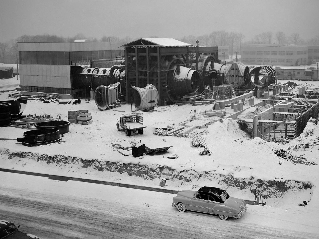
Construction of the Propulsion Systems Laboratory No. 1 and 2 at the National Advisory Committee for Aeronautics (NACA) Lewis Flight Propulsion Laboratory. When it began operation in late 1952, the Propulsion Systems Laboratory was the NACA’s most powerful facility for testing full-scale engines at simulated flight altitudes. The facility contained two altitude simulating test chambers which were a technological combination of the static sea-level test stands and the complex Altitude Wind Tunnel, which recreated actual flight conditions on a larger scale. NACA Lewis began designing the new facility in 1947 as part of a comprehensive plan to improve the altitude testing capabilities across the lab. The exhaust, refrigeration, and combustion air systems from all the major test facilities were linked. In this way, different facilities could be used to complement the capabilities of one another. Propulsion Systems Laboratory construction began in late summer 1949 with the installation of an overhead exhaust pipe connecting the facility to the Altitude Wind Tunnel and Engine Research Building. The large test section pieces arriving in early 1951, when this photograph was taken. The two primary coolers for the altitude exhaust are in place within the framework near the center of the photograph.
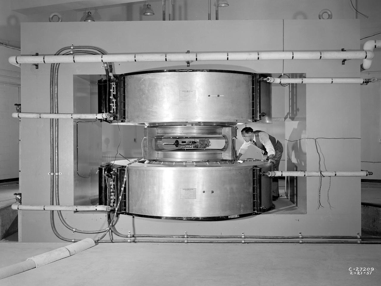
Researcher James Blue examines the new cyclotron at the National Advisory Committee for Aeronautics (NACA) Lewis Flight Propulsion Laboratory. Researchers at NACA Lewis began postulating about the use of atomic power for propulsion immediately after World War II. The NACA concentrated its efforts on the study of high temperature materials and heat transfer since it did not have access to the top secret fission information. The military studied the plausibility of nuclear propulsion for aircraft in the late 1940s. The military program was cancelled after four years without any breakthroughs, but the Atomic Energy Commission took on the effort in 1951. The NACA Lewis laboratory was expanding its nuclear-related research during this period. In 1948, Lewis engineers were assigned to the Oak Ridge National Laboratory to obtain expertise in high temperature heat transfer and advanced materials technology. The following year a new 80-person Nuclear Reactor Division was created, and an in-house nuclear school was established to train these researchers. The cyclotron was built behind the Materials and Structures Laboratory to support thermodynamic and materials research for both nuclear aircraft and nuclear rockets. The original NACA Lewis cyclotron was used to accelerate two kinds of particles. To better match the space radiation environment, the cyclotron was later modified to accelerate particles of the newly-discovered Van Allen radiation belts.
NACA Laboratory Computers Help Compile Handbook: ''Monroe Methods for Algebra, " a new booklet describing short-cuts that can be used in solving frequently-used algebraic formulas with a calculating machine, is undergoing its first trial at the hands of Laboratory computers. Several Monro-matics were purchased recently by NACA. NACA Air Scoop August 17,1951 Page 4.

Flight evaluation and comparison of a NACA submerged inlet and a scoop inlet on the North American YF-93A (AF48-317 NACA-139). The YF-93A's were the first aircraft to use flush NACA engine inlets. aircraft to use flush NACA engine inlets. Note: Used in publication in Flight Research at Ames; 57 Years of Development and Validation of Aeronautical Technology NASA SP-1998-3300 and Memoirs of a Flight Test Engineer NASA SP-2001-4525
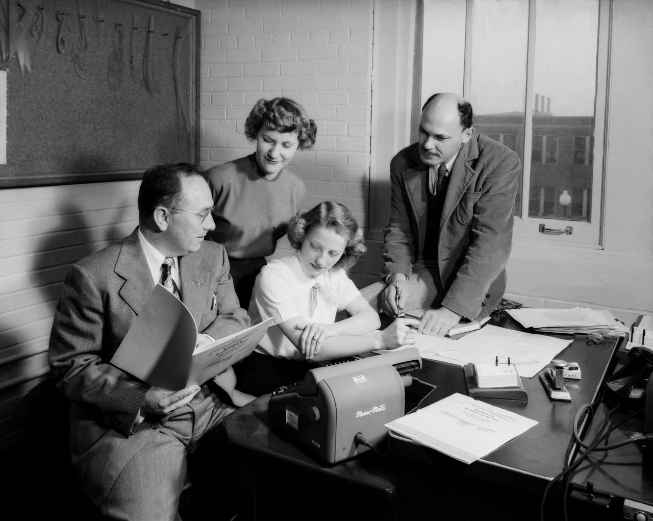
NACA Laboratory Computers Help Compile Handbook: ''Monroe Methods for Algebra, " a new booklet describing short-cuts that can be used in solving frequently-used algebraic formulas with a calculating machine, is undergoing its first trial at the hands of Laboratory computers. Several Monro-matics were purchased recently by NACA. NACA Air Scoop August 17,1951 Page 4.
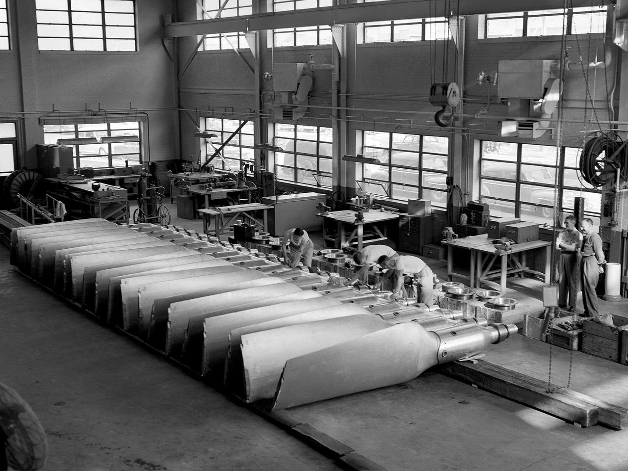
New wooden fan blades being prepared for installation in the Altitude Wind Tunnel at the National Advisory Committee for Aeronautics (NACA) Lewis Flight Propulsion Laboratory. The facility underwent a major upgrade in 1951 to increase its operating capacities in order to handle the new, more powerful turbojet engines being manufactured in the 1950s. The fan blades were prepared in the shop area, seen in this photograph, before being lowered through a hole in the tunnel and attached to the drive shaft. A new drive bearing and tail faring were also installed on the fan as part of this rehab project. A 12-bladed 31-foot-diameter spruce wood fan generated the 300 to 500 mile-per-hour airflow through the tunnel. An 18,000-horsepower General Electric induction motor located in the rear corner of the Exhauster Building drove the fan at 410 revolutions per minute. An extension shaft, sealed in the tunnel’s shell with flexible couplings that allowed for the movement of the shell, connected the motor to the fan. A bronze screen secured to the turning vanes protected the fan against damage from any engine parts sailing through the tunnel. Despite this screen the blades did become worn or cracked over time and had to be replaced.
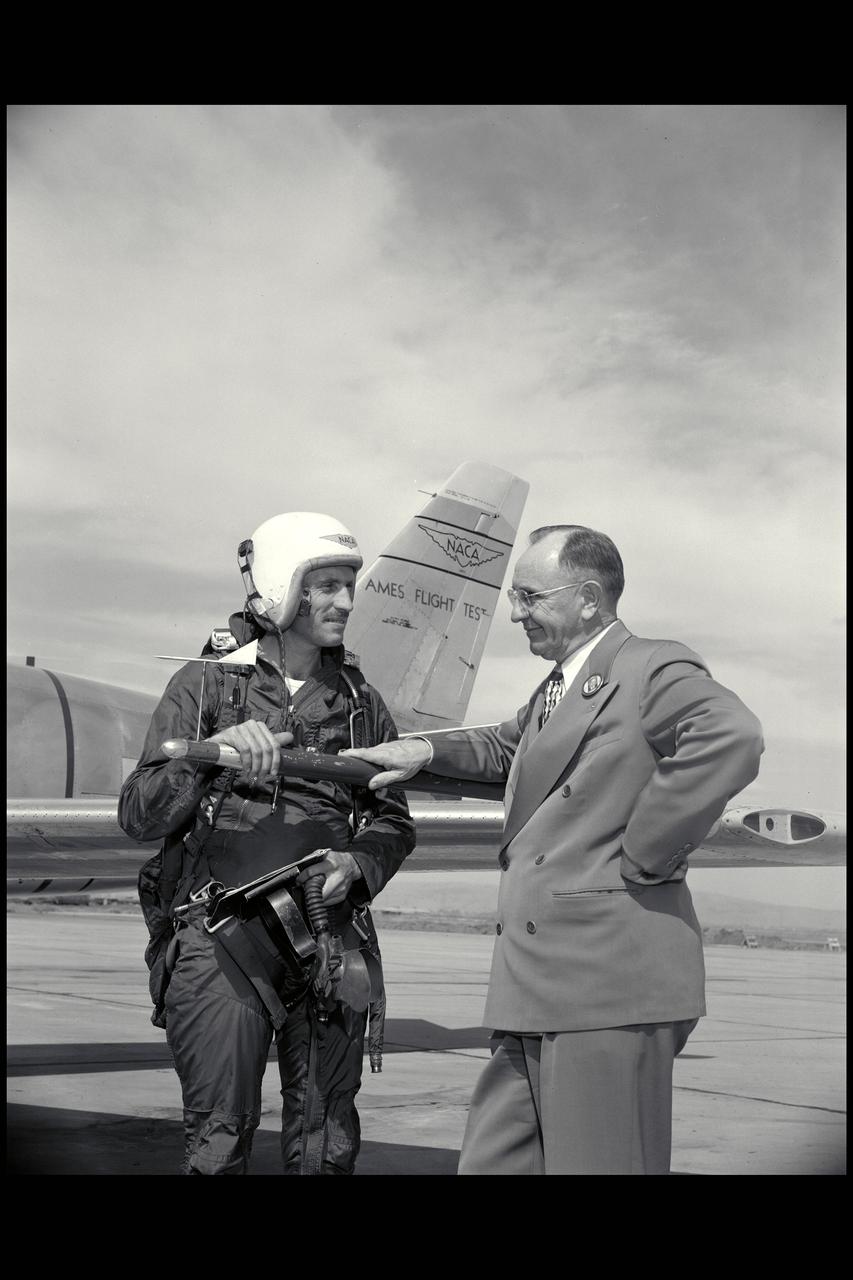
Ames Pilot George Cooper (l) and Ames Director Smith DeFrance discuss F-86 flight test
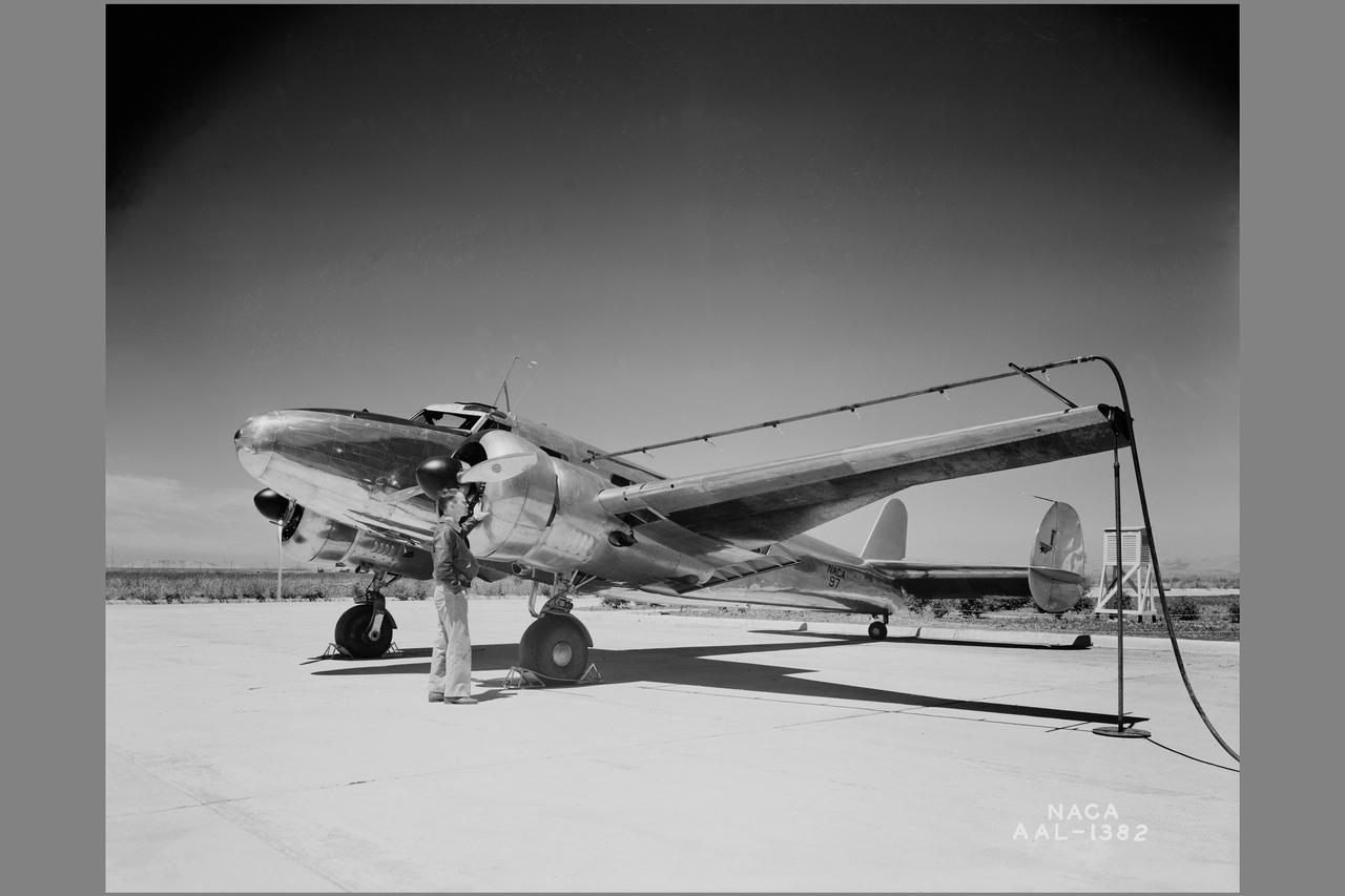
Lockheed 12A ground tests of cellular type heated wing
NACA Laboratory Computers Help Compile Handbook: ''Monroe Methods for Algebra, " a new booklet describing short-cuts that can be used in solving frequently-used algebraic formulas with a calculating machine, is undergoing its first trial at thehands of Laboratory computers. Several Monro-matics were purchased recently by NACA. In photo are W.H. Rankins discusses the "Monroe Methods for Algebra" with Gladys Storey (seated) and Ferne Gapcynski, both of 16 foot Hight Speed Tunnel. NACA Air Scoop August 17,1951 Page 4.
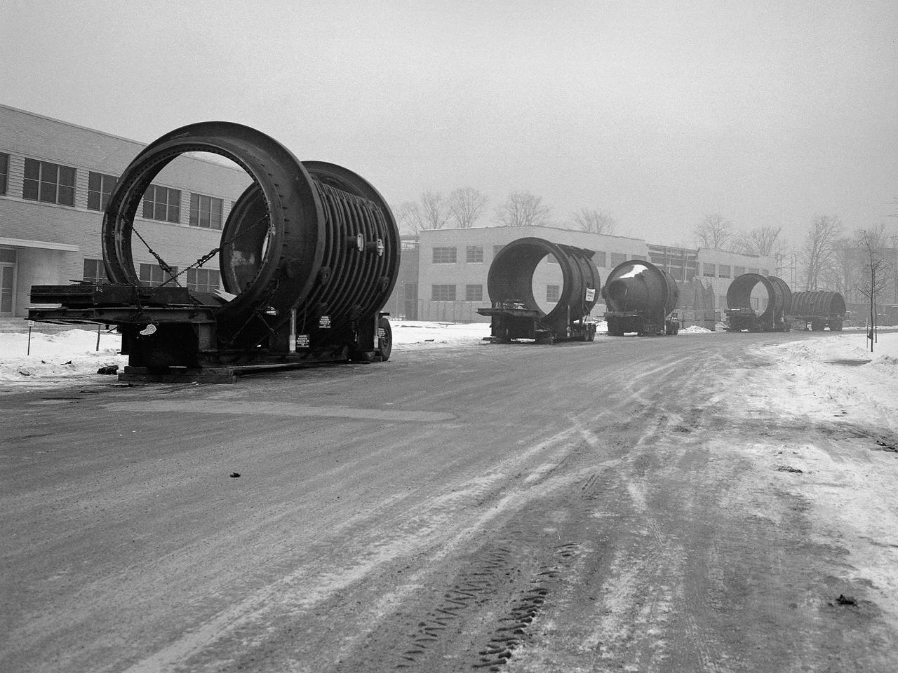
A caravan of large steel castings arrived at the National Advisory Committee for Aeronautics (NACA) Lewis Flight Propulsion Laboratory in January 1951. These pieces would serve as the two 14-foot diameter test chambers in the new Propulsion Systems Laboratory (PSL). NACA Lewis specialized in aircraft engines and offered many engine test facilities. In the late 1940s, however, the NACA realized a larger facility was required to test the newest jet engines. When completed in October 1952, PSL became the nation’s most powerful facility for testing full-scale engines at simulated flight altitudes. NACA engineers began designing the PSL in 1947, and excavations commenced in September 1949. In the spring of 1950, the facility’s supports were erected, and the two large exhaust gas coolers were installed. Work on the Access Building began in early 1951 with the arrival of the large test section pieces, seen in this photograph. The massive pieces were delivered to the area from the Henry Pratt Company by rail and then loaded on a series of flatbed trucks that transported them to Lewis. The nearest vehicle has one of the clamshell access hatches. PSL was initially used to study the jet engines of the early 1950s and ramjets for missile programs such as Navaho and Bomarc. With the advent of the space program in the late 1950s, the facility was used to investigate complex rocket engines, including the Pratt and Whitney RL-10.
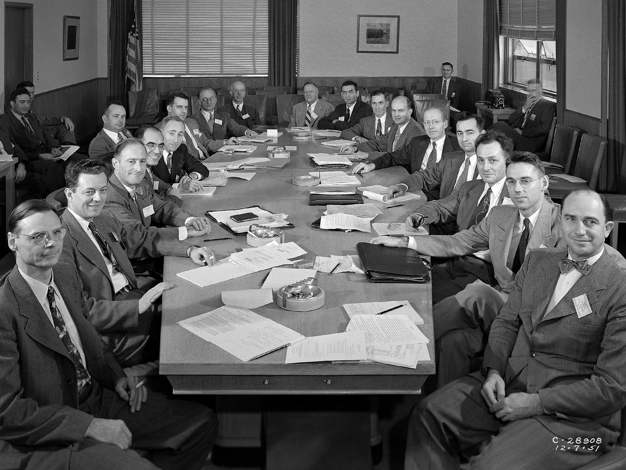
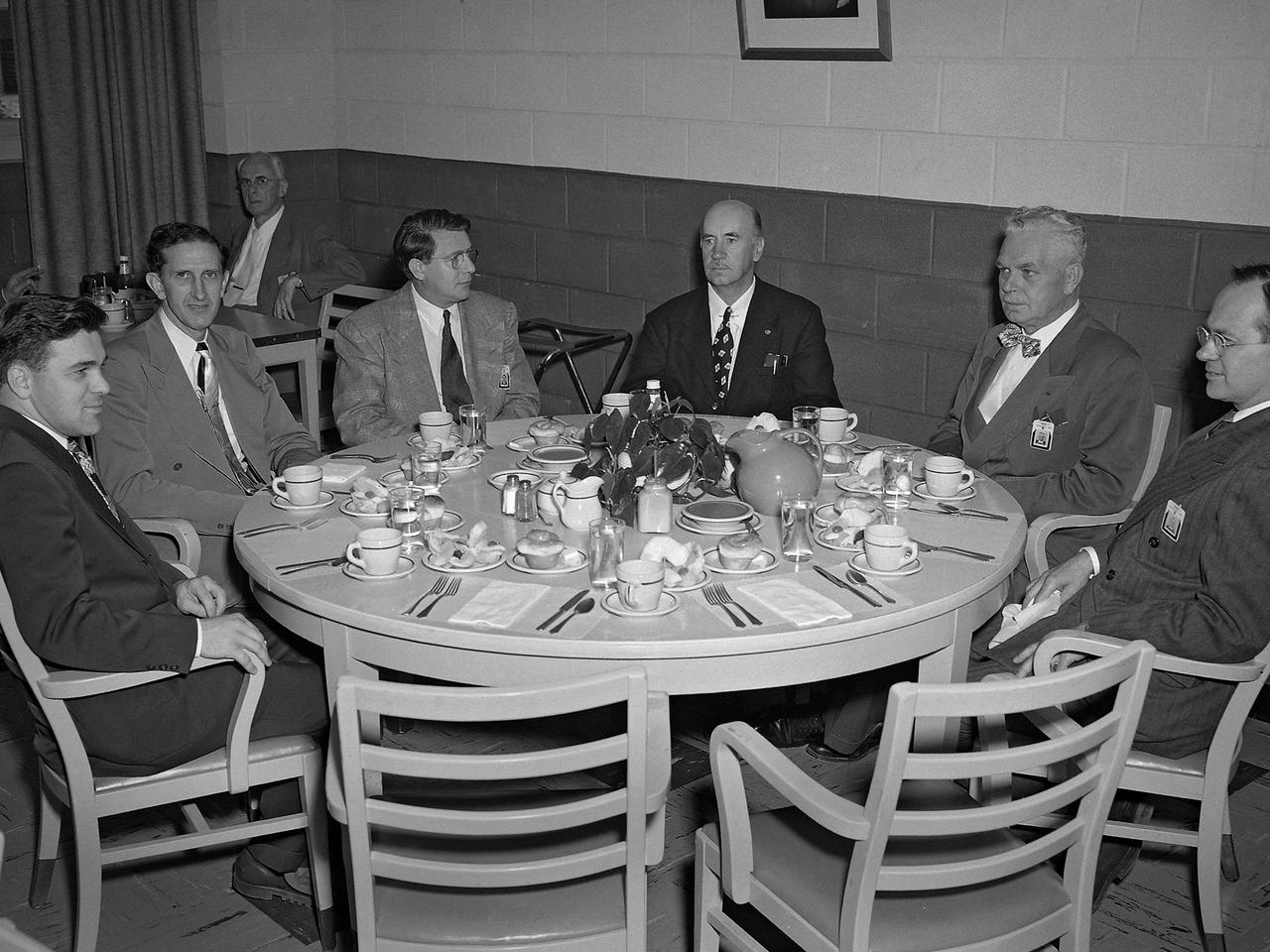
The National Advisory Committee for Aeronautics (NACA) Subcommittee on Combustion holds a meeting at Lewis Flight Propulsion Laboratory in Cleveland, Ohio. The NACA was managed by committees that included members of their own staff along with representatives from industry, the military, other government agencies, and universities. The 17-person Executive Committee was the NACA’s primary administrative body. They met several times a year at the NACA headquarters office in Washington DC to discuss broad issues confronting the US aeronautical community. Jerome Hunsaker, head of the Department of Aeronautical Engineering at the Massachusetts Institute of Technology, served as the NACA chairman from 1941 to 1956. George Lewis was not a member of the Executive Committee but served a key role as the NACA’s Director of Aeronautical Research. The NACA’s organizational chart also included 11 technical committees, several of which had specialized subcommittees. There were over 100 different subcommittees between World War I and 1958. The number of active subcommittees varied over the years. Most existed only for a few years, but some continued for over a decade. The subcommittees met three or four times per year, often at the laboratory most closely associated with the area of research. A team of laboratory researchers presented briefings on their recent activities and plans for the future. The Subcommittee on Combustion existed from 1945 to the NACA’s demise in 1958.
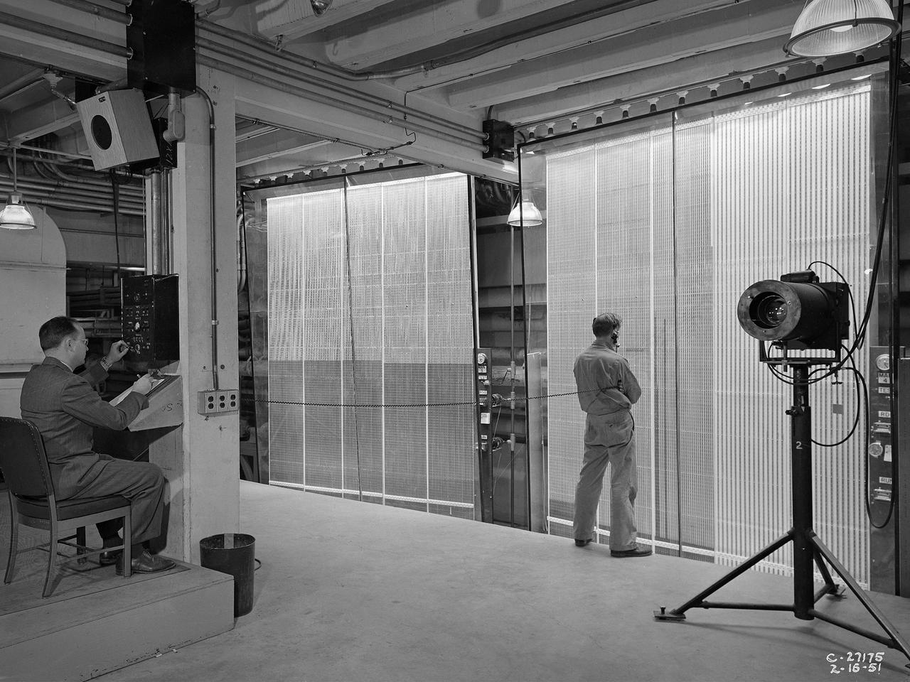
Analysts at the National Advisory Committee for Aeronautics (NACA) Lewis Flight Propulsion Laboratory take data readings from rows of manometers in the basement of the 8- by 6-Foot Supersonic Wind Tunnel. Manometers were mercury-filled glass tubes that indicated different pressure levels in the test section. Manometers look and function very similarly to thermometers. Pressure sensing instruments were installed on the test article inside the wind tunnel or other test facility. Each test could have dozens of such instruments installed and connected to a remotely located manometer tube. The mercury inside the manometer rose and fell with the pressure levels. The dark mercury can be seen at different levels within the tubes. Since the pressure readings were dynamic, it was necessary to note the levels at given points during the test. This was done using both female computers and photography. A camera is seen on a stand to the right in this photograph.
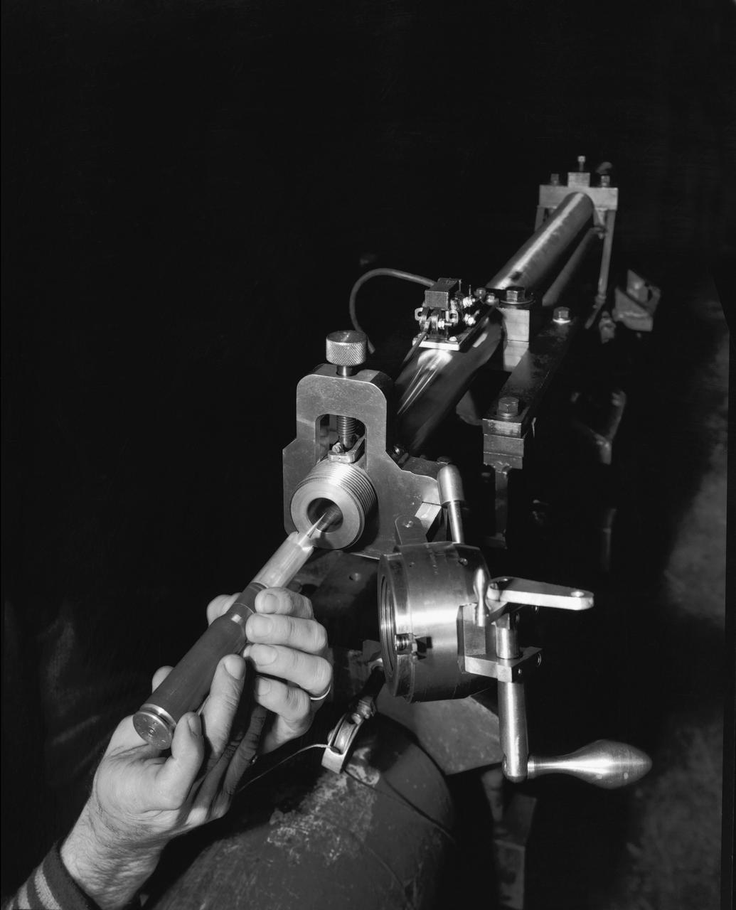
Supersonic Free Flight Wind Tunnel 620 gun and model; model, sabot and cartridge assembly and ready for firing in the supersonic free flight tunnel
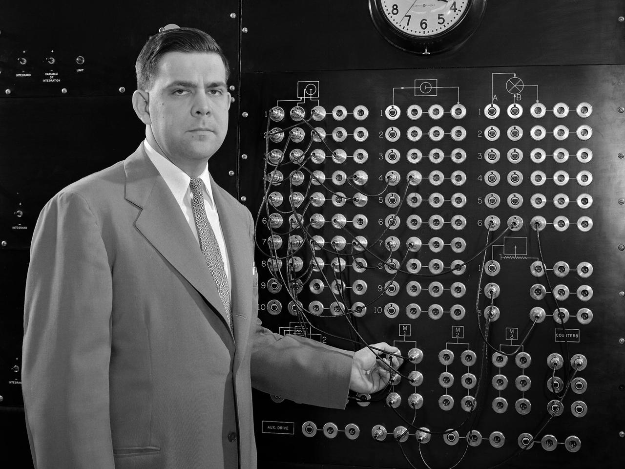
Harry Mergler stands at the control board of a differential analyzer in the new Instrument Research Laboratory at the National Advisory Committee for Aeronautics (NACA) Lewis Flight Propulsion Laboratory. The differential analyzer was a multi-variable analog computation machine devised in 1931 by Massachusetts Institute of Technology researcher and future NACA Committee member Vannevar Bush. The mechanical device could solve computations up to the sixth order, but had to be rewired before each new computation. Mergler modified Bush’s differential analyzer in the late 1940s to calculate droplet trajectories for Lewis’ icing research program. In four days Mergler’s machine could calculate what previously required weeks. NACA Lewis built the Instrument Research Laboratory in 1950 and 1951 to house the large analog computer equipment. The two-story structure also provided offices for the Mechanical Computational Analysis, and Flow Physics sections of the Physics Division. The division had previously operated from the lab’s hangar because of its icing research and flight operations activities. Mergler joined the Instrument Research Section of the Physics Division in 1948 after earning an undergraduate degree in Physics from the Case Institute of Technology. Mergler’s focus was on the synthesis of analog computers with the machine tools used to create compressor and turbine blades for jet engines.